
Solution Description
85
FlexiHybrid Solution Description A25000-A0300-F008-02-76P1 Issue: 2 Issue date: January 2010
-
Upload
david-jose-barrios-itriago -
Category
Documents
-
view
9 -
download
5
description
Flexyhibrit
Transcript of Solution Description

FlexiHybrid
Solution Description
A25000-A0300-F008-02-76P1
Issue: 2 Issue date: January 2010

2 A25000-A0300-F008-02-76P1Issue: 2 Issue date: January 2010
Solution Description
The information in this document is subject to change without notice and describes only the product defined in the introduction of this documentation. This documentation is intended for the use of Nokia Siemens Networks customers only for the purposes of the agreement under which the document is submitted, and no part of it may be used, reproduced, modified or transmitted in any form or means without the prior written permission of Nokia Siemens Networks. The documentation has been prepared to be used by professional and properly trained personnel, and the customer assumes full responsibility when using it. Nokia Siemens Networks welcomes customer comments as part of the process of continuous development and improvement of the documentation.
The information or statements given in this documentation concerning the suitability, capacity, or performance of the mentioned hardware or software products are given "as is" and all liability arising in connection with such hardware or software products shall be defined conclusively and finally in a separate agreement between Nokia Siemens Networks and the customer. However, Nokia Siemens Networks has made all reasonable efforts to ensure that the instructions contained in the document are adequate and free of material errors and omissions. Nokia Siemens Networks will, if deemed necessary by Nokia Siemens Networks, explain issues which may not be covered by the document.
Nokia Siemens Networks will correct errors in this documentation as soon as possible. IN NO EVENT WILL NOKIA SIEMENS NETWORKS BE LIABLE FOR ERRORS IN THIS DOCUMEN-TATION OR FOR ANY DAMAGES, INCLUDING BUT NOT LIMITED TO SPECIAL, DIRECT, INDIRECT, INCIDENTAL OR CONSEQUENTIAL OR ANY LOSSES, SUCH AS BUT NOT LIMITED TO LOSS OF PROFIT, REVENUE, BUSINESS INTERRUPTION, BUSINESS OPPORTUNITY OR DATA,THAT MAY ARISE FROM THE USE OF THIS DOCUMENT OR THE INFORMATION IN IT.
This documentation and the product it describes are considered protected by copyrights and other intellectual property rights according to the applicable laws.
The wave logo is a trademark of Nokia Siemens Networks Oy. Nokia is a registered trademark of Nokia Corporation. Siemens is a registered trademark of Siemens AG.
Other product names mentioned in this document may be trademarks of their respective owners, and they are mentioned for identification purposes only.
Copyright © Nokia Siemens Networks 2010. All rights reserved.
f Important Notice on Product SafetyElevated voltages are inevitably present at specific points in this electrical equipment. Some of the parts may also have elevated operating temperatures.
Non-observance of these conditions and the safety instructions can result in personal injury or in property damage.
Therefore, only trained and qualified personnel may install and maintain the system.
The system complies with the standard EN 60950 / IEC 60950. All equipment connected has to comply with the applicable safety standards.
The same text in German:
Wichtiger Hinweis zur Produktsicherheit
In elektrischen Anlagen stehen zwangsläufig bestimmte Teile der Geräte unter Span-nung. Einige Teile können auch eine hohe Betriebstemperatur aufweisen.
Eine Nichtbeachtung dieser Situation und der Warnungshinweise kann zu Körperverlet-zungen und Sachschäden führen.
Deshalb wird vorausgesetzt, dass nur geschultes und qualifiziertes Personal die Anlagen installiert und wartet.
Das System entspricht den Anforderungen der EN 60950 / IEC 60950. Angeschlossene Geräte müssen die zutreffenden Sicherheitsbestimmungen erfüllen.

A25000-A0300-F008-02-76P1Issue: 2 Issue date: January 2010
3
Solution Description
Table of ContentsThis document has 85 pages.
1 Preface . . . . . . . . . . . . . . . . . . . . . . . . . . . . . . . . . . . . . . . . . . . . . . . . . . 91.1 Intended audience . . . . . . . . . . . . . . . . . . . . . . . . . . . . . . . . . . . . . . . . . . 91.2 Structure of this document . . . . . . . . . . . . . . . . . . . . . . . . . . . . . . . . . . . . 91.3 Symbols and conventions . . . . . . . . . . . . . . . . . . . . . . . . . . . . . . . . . . . . 91.4 History of changes . . . . . . . . . . . . . . . . . . . . . . . . . . . . . . . . . . . . . . . . . 111.5 Waste electrical and electronic equipment (WEEE) . . . . . . . . . . . . . . . 111.6 RoHS compliance . . . . . . . . . . . . . . . . . . . . . . . . . . . . . . . . . . . . . . . . . 11
2 Overview . . . . . . . . . . . . . . . . . . . . . . . . . . . . . . . . . . . . . . . . . . . . . . . . 13
3 Solution structure. . . . . . . . . . . . . . . . . . . . . . . . . . . . . . . . . . . . . . . . . . 183.1 IDU-ODU interconnection . . . . . . . . . . . . . . . . . . . . . . . . . . . . . . . . . . . 203.1.1 Radio signal . . . . . . . . . . . . . . . . . . . . . . . . . . . . . . . . . . . . . . . . . . . . . . 203.1.2 IDU/ODU service auxiliary channel . . . . . . . . . . . . . . . . . . . . . . . . . . . . 203.1.3 ODU power supply. . . . . . . . . . . . . . . . . . . . . . . . . . . . . . . . . . . . . . . . . 20
4 Applications . . . . . . . . . . . . . . . . . . . . . . . . . . . . . . . . . . . . . . . . . . . . . . 21
5 Features. . . . . . . . . . . . . . . . . . . . . . . . . . . . . . . . . . . . . . . . . . . . . . . . . 265.1 Modulations and capacities . . . . . . . . . . . . . . . . . . . . . . . . . . . . . . . . . . 265.2 Basic configurations. . . . . . . . . . . . . . . . . . . . . . . . . . . . . . . . . . . . . . . . 305.2.1 Standard terminal . . . . . . . . . . . . . . . . . . . . . . . . . . . . . . . . . . . . . . . . . 305.2.2 Protected terminal . . . . . . . . . . . . . . . . . . . . . . . . . . . . . . . . . . . . . . . . . 315.2.3 Ring configuration (East-West) . . . . . . . . . . . . . . . . . . . . . . . . . . . . . . . 345.3 Equipment composition . . . . . . . . . . . . . . . . . . . . . . . . . . . . . . . . . . . . . 355.4 Link Terminals with different configuration. . . . . . . . . . . . . . . . . . . . . . . 435.5 Ethernet payload Processing. . . . . . . . . . . . . . . . . . . . . . . . . . . . . . . . . 445.5.1 Maximum bit rate over the air . . . . . . . . . . . . . . . . . . . . . . . . . . . . . . . . 445.5.2 Port Setting . . . . . . . . . . . . . . . . . . . . . . . . . . . . . . . . . . . . . . . . . . . . . . 485.5.3 Learning functionality . . . . . . . . . . . . . . . . . . . . . . . . . . . . . . . . . . . . . . . 485.5.4 Forwarding functionality . . . . . . . . . . . . . . . . . . . . . . . . . . . . . . . . . . . . . 485.5.5 Ethernet Latency . . . . . . . . . . . . . . . . . . . . . . . . . . . . . . . . . . . . . . . . . . 485.5.6 VLAN management and Max packet size . . . . . . . . . . . . . . . . . . . . . . . 495.5.7 Buffer size . . . . . . . . . . . . . . . . . . . . . . . . . . . . . . . . . . . . . . . . . . . . . . . 495.5.8 Counters, Link monitoring . . . . . . . . . . . . . . . . . . . . . . . . . . . . . . . . . . . 505.5.9 QoS . . . . . . . . . . . . . . . . . . . . . . . . . . . . . . . . . . . . . . . . . . . . . . . . . . . . 505.5.9.1 QoS in Standard and Enhanced Master IO modules. . . . . . . . . . . . . . . 505.5.9.2 QoS in Standard2, Enhanced2 and 42xE1 Master IO modules. . . . . . . 515.5.9.3 QoS in GigEth and GigEth Enhanced Master IO module . . . . . . . . . . . 525.6 Ethernet payload Processing in Standard2 and Enhanced2 Master IO Mod-
ules . . . . . . . . . . . . . . . . . . . . . . . . . . . . . . . . . . . . . . . . . . . . . . . . . . . . 545.6.1 Maximum Bit-Rate Over The Air . . . . . . . . . . . . . . . . . . . . . . . . . . . . . . 545.6.2 Port Setting . . . . . . . . . . . . . . . . . . . . . . . . . . . . . . . . . . . . . . . . . . . . . . 545.6.3 Learning Functionality . . . . . . . . . . . . . . . . . . . . . . . . . . . . . . . . . . . . . . 555.6.4 Forwarding Functionality . . . . . . . . . . . . . . . . . . . . . . . . . . . . . . . . . . . . 555.6.5 VLAN Management and Maximum Packet Size . . . . . . . . . . . . . . . . . . 55

4 A25000-A0300-F008-02-76P1Issue: 2 Issue date: January 2010
Solution Description
5.6.6 Throughput, Latency, and Back-to-Back Limits . . . . . . . . . . . . . . . . . . . 555.6.7 Buffer size . . . . . . . . . . . . . . . . . . . . . . . . . . . . . . . . . . . . . . . . . . . . . . . . 575.6.8 Counters, Link monitoring . . . . . . . . . . . . . . . . . . . . . . . . . . . . . . . . . . . . 575.6.9 QoS. . . . . . . . . . . . . . . . . . . . . . . . . . . . . . . . . . . . . . . . . . . . . . . . . . . . . 575.7 Ethernet Functionality Summary. . . . . . . . . . . . . . . . . . . . . . . . . . . . . . . 595.8 Spanning Tree . . . . . . . . . . . . . . . . . . . . . . . . . . . . . . . . . . . . . . . . . . . . 605.9 100Mbps-PLUS Ethernet . . . . . . . . . . . . . . . . . . . . . . . . . . . . . . . . . . . . 605.10 APC (Adaptive Power Control) . . . . . . . . . . . . . . . . . . . . . . . . . . . . . . . . 605.11 ACM (Adaptive Coding / Modulation) . . . . . . . . . . . . . . . . . . . . . . . . . . . 635.11.1 Scope of ACM Applicability. . . . . . . . . . . . . . . . . . . . . . . . . . . . . . . . . . . 645.11.2 Released configurations for ACM in SVR 2.1 . . . . . . . . . . . . . . . . . . . . . 665.11.3 ACM Configuration Parameters . . . . . . . . . . . . . . . . . . . . . . . . . . . . . . . 665.12 Cross-Connections . . . . . . . . . . . . . . . . . . . . . . . . . . . . . . . . . . . . . . . . . 685.12.1 Termination Points identification . . . . . . . . . . . . . . . . . . . . . . . . . . . . . . . 685.12.2 Bidirectional Connections . . . . . . . . . . . . . . . . . . . . . . . . . . . . . . . . . . . . 705.12.3 Ring Cross-Connections . . . . . . . . . . . . . . . . . . . . . . . . . . . . . . . . . . . . . 715.13 STM-1 Mux/Demux (Optional) . . . . . . . . . . . . . . . . . . . . . . . . . . . . . . . . 735.14 Loop-back . . . . . . . . . . . . . . . . . . . . . . . . . . . . . . . . . . . . . . . . . . . . . . . . 745.14.1 E1 Loopbacks . . . . . . . . . . . . . . . . . . . . . . . . . . . . . . . . . . . . . . . . . . . . . 745.14.1.1 Loopbacks for the aggregate signal . . . . . . . . . . . . . . . . . . . . . . . . . . . . 745.14.1.2 Loopbacks for a single E1 stream. . . . . . . . . . . . . . . . . . . . . . . . . . . . . . 755.14.2 STM-1 loopbacks . . . . . . . . . . . . . . . . . . . . . . . . . . . . . . . . . . . . . . . . . . 765.14.2.1 Loopbacks with STM-1 transparent . . . . . . . . . . . . . . . . . . . . . . . . . . . . 765.14.2.2 Loopbacks with STM-1 with MUX/DEMUX option . . . . . . . . . . . . . . . . . 76
6 Management . . . . . . . . . . . . . . . . . . . . . . . . . . . . . . . . . . . . . . . . . . . . . . 776.1 IDU and Network management. . . . . . . . . . . . . . . . . . . . . . . . . . . . . . . . 776.2 IP address. . . . . . . . . . . . . . . . . . . . . . . . . . . . . . . . . . . . . . . . . . . . . . . . 776.3 Network. . . . . . . . . . . . . . . . . . . . . . . . . . . . . . . . . . . . . . . . . . . . . . . . . . 776.4 NMS Network Operational Principles . . . . . . . . . . . . . . . . . . . . . . . . . . . 776.5 Third Party Network Management Software Support . . . . . . . . . . . . . . . 78
7 Solution technical specifications . . . . . . . . . . . . . . . . . . . . . . . . . . . . . . . 79
8 Acronyms and abbreviations. . . . . . . . . . . . . . . . . . . . . . . . . . . . . . . . . . 82

A25000-A0300-F008-02-76P1Issue: 2 Issue date: January 2010
5
Solution Description
List of FiguresFigure 1 WEEE label . . . . . . . . . . . . . . . . . . . . . . . . . . . . . . . . . . . . . . . . . . . . . . 11Figure 2 Microwave Split Mount Architecture Architecture . . . . . . . . . . . . . . . . . 14Figure 3 “FlexiHybrid” Equipment in (1+0) configuration . . . . . . . . . . . . . . . . . . . 19Figure 4 Applications 1 - Mobile Networks- 1st Mile . . . . . . . . . . . . . . . . . . . . . . . 21Figure 5 Applications 2 - Mobile Networks-Aggregation layer Hybrid backhaul (1) .
22Figure 6 Applications 2 - Mobile Networks-Aggregation layer Hybrid backhaul (2) .
22Figure 7 Applications 2 - Mobile Networks-Aggregation layer Hybrid backhaul (3) .
23Figure 8 Applications 2 - Mobile Networks-Aggregation layer Hybrid backhaul (4) .
23Figure 9 PDH Ring. . . . . . . . . . . . . . . . . . . . . . . . . . . . . . . . . . . . . . . . . . . . . . . . 24Figure 10 Ethernet Ring (1) . . . . . . . . . . . . . . . . . . . . . . . . . . . . . . . . . . . . . . . . . . 24Figure 11 Ethernet Ring (2) . . . . . . . . . . . . . . . . . . . . . . . . . . . . . . . . . . . . . . . . . . 25Figure 12 Ethernet Applications. . . . . . . . . . . . . . . . . . . . . . . . . . . . . . . . . . . . . . . 25Figure 13 1+0 (Standard) terminal . . . . . . . . . . . . . . . . . . . . . . . . . . . . . . . . . . . . . 31Figure 14 1+1 protected diversity mode. . . . . . . . . . . . . . . . . . . . . . . . . . . . . . . . . 32Figure 15 1+1 protection in non-diversity mode. . . . . . . . . . . . . . . . . . . . . . . . . . . 33Figure 16 Ring . . . . . . . . . . . . . . . . . . . . . . . . . . . . . . . . . . . . . . . . . . . . . . . . . . . . 34Figure 17 1+0 system with integrated antenna . . . . . . . . . . . . . . . . . . . . . . . . . . . 36Figure 18 1+0 system with independent antenna . . . . . . . . . . . . . . . . . . . . . . . . . 37Figure 19 1+1 system with Hot Standby or FD with integrated antenna . . . . . . . . 38Figure 20 1+1 system Hot Standby or FD with independent antenna . . . . . . . . . . 39Figure 21 1+1 system with dual polarization . . . . . . . . . . . . . . . . . . . . . . . . . . . . . 40Figure 22 1+1 SD system with two separated antennas . . . . . . . . . . . . . . . . . . . . 41Figure 23 East-West (2+0 system with different destinations or Ring) with integrated
antennas . . . . . . . . . . . . . . . . . . . . . . . . . . . . . . . . . . . . . . . . . . . . . . . . 42Figure 24 Link terminals with different configuration . . . . . . . . . . . . . . . . . . . . . . . 43Figure 25 Single Network Operation . . . . . . . . . . . . . . . . . . . . . . . . . . . . . . . . . . . 45Figure 26 Two-Network Operation. . . . . . . . . . . . . . . . . . . . . . . . . . . . . . . . . . . . . 46Figure 27 Priority assignment logic scheme (Standard and Enhanced Master IO Mod-
ules) . . . . . . . . . . . . . . . . . . . . . . . . . . . . . . . . . . . . . . . . . . . . . . . . . . . . 51Figure 28 Priority assignment logic scheme . . . . . . . . . . . . . . . . . . . . . . . . . . . . . 52Figure 29 Priority assignment logic scheme . . . . . . . . . . . . . . . . . . . . . . . . . . . . . 53Figure 30 Rx side. . . . . . . . . . . . . . . . . . . . . . . . . . . . . . . . . . . . . . . . . . . . . . . . . . 61Figure 31 Tx side . . . . . . . . . . . . . . . . . . . . . . . . . . . . . . . . . . . . . . . . . . . . . . . . . . 62Figure 32 Time diagram. . . . . . . . . . . . . . . . . . . . . . . . . . . . . . . . . . . . . . . . . . . . . 62Figure 33 Physical location of E1 TP . . . . . . . . . . . . . . . . . . . . . . . . . . . . . . . . . . . 68Figure 34 TP name and associated Prefix . . . . . . . . . . . . . . . . . . . . . . . . . . . . . . . 69Figure 35 Standard Cross connection with related syntax. . . . . . . . . . . . . . . . . . . 70Figure 36 E1 Data Connection. . . . . . . . . . . . . . . . . . . . . . . . . . . . . . . . . . . . . . . . 71Figure 37 Protected E1 data connection . . . . . . . . . . . . . . . . . . . . . . . . . . . . . . . . 71Figure 38 Normal E1 data path within the IDU. . . . . . . . . . . . . . . . . . . . . . . . . . . . 72Figure 39 Protected E1 data path within the IDU. . . . . . . . . . . . . . . . . . . . . . . . . . 72Figure 40 Ring Cross connection with related syntax . . . . . . . . . . . . . . . . . . . . . . 73

6 A25000-A0300-F008-02-76P1Issue: 2 Issue date: January 2010
Solution Description
Figure 41 STM-1 Mux/Demux Capability . . . . . . . . . . . . . . . . . . . . . . . . . . . . . . . . 74Figure 42 Local LIU loop-back . . . . . . . . . . . . . . . . . . . . . . . . . . . . . . . . . . . . . . . . 75Figure 43 Local Modem loop-back . . . . . . . . . . . . . . . . . . . . . . . . . . . . . . . . . . . . . 75Figure 44 Remote LIU loop-back . . . . . . . . . . . . . . . . . . . . . . . . . . . . . . . . . . . . . . 75Figure 45 PC and IDU on same subnet . . . . . . . . . . . . . . . . . . . . . . . . . . . . . . . . . 78Figure 46 IDU on different subnets . . . . . . . . . . . . . . . . . . . . . . . . . . . . . . . . . . . . . 78

A25000-A0300-F008-02-76P1Issue: 2 Issue date: January 2010
7
Solution Description
List of TablesTable 1 Structure of this document . . . . . . . . . . . . . . . . . . . . . . . . . . . . . . . . . . . 9Table 2 List of conventions used in this document . . . . . . . . . . . . . . . . . . . . . . . 9Table 3 History of changes . . . . . . . . . . . . . . . . . . . . . . . . . . . . . . . . . . . . . . . . 11Table 4 RF Channeling . . . . . . . . . . . . . . . . . . . . . . . . . . . . . . . . . . . . . . . . . . . 14Table 5 Modulation format supported for each bandwidth . . . . . . . . . . . . . . . . . 26Table 6 Summary of Modes Supported up to SVR 2.1 . . . . . . . . . . . . . . . . . . . 26Table 7 Modes and ETSI Class Certification . . . . . . . . . . . . . . . . . . . . . . . . . . . 27Table 8 Modulations, Channel bandwidth and supported payloads . . . . . . . . . 27Table 9 Configurations . . . . . . . . . . . . . . . . . . . . . . . . . . . . . . . . . . . . . . . . . . . . 30Table 10 Equipment composition . . . . . . . . . . . . . . . . . . . . . . . . . . . . . . . . . . . . 35Table 11 Equipment composition according to the configuration . . . . . . . . . . . . 35Table 12 Over the air compatibility for Master IO modules (link terminals are intend-
ed to have the same SVR) . . . . . . . . . . . . . . . . . . . . . . . . . . . . . . . . . . 43Table 13 Over the air compatibility for Master IO modules (link terminals are intend-
ed to have the same SVR) . . . . . . . . . . . . . . . . . . . . . . . . . . . . . . . . . . 44Table 14 Standard and Enhanced Master I/O Card . . . . . . . . . . . . . . . . . . . . . . . 48Table 15 Gigabit Master I/O Card . . . . . . . . . . . . . . . . . . . . . . . . . . . . . . . . . . . . 49Table 16 42xE1Master I/O Card . . . . . . . . . . . . . . . . . . . . . . . . . . . . . . . . . . . . . 49Table 17 Throughput on Standard2 and Enhanced2 IO Modules (%) . . . . . . . . . 55Table 18 Throughput on Standard2 and Enhanced2 IO Modules (Mbit/s) . . . . . 56Table 19 Latency on Standard2 and Enhanced2 IO Modules . . . . . . . . . . . . . . . 56Table 20 Back-to-back frames limits on Standard2 and Enhanced2 IO Modules 57Table 21 Summary of Ethernet Characteristics . . . . . . . . . . . . . . . . . . . . . . . . . . 59Table 22 Released ACM modes and Parameters . . . . . . . . . . . . . . . . . . . . . . . . 66Table 23 TP identification and Prefix Syntax . . . . . . . . . . . . . . . . . . . . . . . . . . . . 69Table 24 Module interfaces . . . . . . . . . . . . . . . . . . . . . . . . . . . . . . . . . . . . . . . . . 70Table 25 General technical specifications . . . . . . . . . . . . . . . . . . . . . . . . . . . . . . 79Table 26 RTPC range (6-13 GHz) . . . . . . . . . . . . . . . . . . . . . . . . . . . . . . . . . . . . 80Table 27 RTPC range (15-38 GHz) . . . . . . . . . . . . . . . . . . . . . . . . . . . . . . . . . . . 80Table 28 Max output power (at ODU flange) . . . . . . . . . . . . . . . . . . . . . . . . . . . . 80Table 29 BER = 10-6 Rx threshold (dBm) . . . . . . . . . . . . . . . . . . . . . . . . . . . . . . 81Table 30 Total power consumption (W) . . . . . . . . . . . . . . . . . . . . . . . . . . . . . . . . 81

8 A25000-A0300-F008-02-76P1Issue: 2 Issue date: January 2010
Solution Description

A25000-A0300-F008-02-76P1Issue: 2 Issue date: January 2010
9
Solution Description Preface
1 PrefaceThis document provides the technical description and the technical specifications of the FlexiHybrid, a radio system operating in the RF bands from 6 GHz to 38 GHz.
1.1 Intended audienceThis document is intended to the radio network planners and to the technicians in charge to operate and maintain the FlexiHybrid.
1.2 Structure of this documentThe document is divided into the following main chapters:
1.3 Symbols and conventionsThe following symbols and conventions are used in this document:
Chapter Title Subject
Chapter 1 Preface Provides an introduction to the document
Chapter 2 Overview Provides an overview on the FlexiHybrid
Chapter 3 Solution structure Provides a description of the parts of the equipment
Chapter 4 Applications Provides the main applications that can be implemented with the FlexiHybrid
Chapter 5 Features Provides the main features
Chapter 6 Management Provides the information regarding the management of the FlexiHybrid
Chapter 7 Solution technical specifica-tions
Lists the technical data
Chapter 8 Acronyms and abbreviations Lists the acronyms and abbreviations used in this document
Table 1 Structure of this document
Representation Meaning
Bold Text in the graphical user interface (window and wizard titles, field names, buttons, etc.) is represented in bold face.
Example: Click Shutdown and then click OK to turn off the com-puter.
Table 2 List of conventions used in this document

10 A25000-A0300-F008-02-76P1Issue: 2 Issue date: January 2010
Solution DescriptionPreface
Italic Field values, file names, file extensions, folder and directory names are denoted by italic text.
Examples: Enter 192.168.0.1 in the IP address field. Click OK to produce a .pdf file.
Courier Command and screen output are denoted by courier font.
Example: ping -t 192.168.0.1
<Angle brackets> Place holders for distinct names or values are represented by enclosing them in <angle brackets>. If a file name is involved, italic text will also be used.
Example: The naming convention for the log files is <NEname>.txt, where <NEname> is the name of the NE sending the messages.
Keyboard button Keyboard keys are represented with a surrounding box.
Example: Press Enter .
[Square brackets] Keyboard shortcuts are represented using square brackets.
Example: Press [CTRL+ALT+DEL] to open the Task Manager.
> The “>” symbol is used as short form to define a path through indi-vidual elements of the graphical user interface, e.g., menus and menu commands.
Example: On the Windows taskbar, select Start > Programs > TNMS > Client menu command to start the TNMS Core/CDM Client.
☞ A tip provides additional information related to the topic described.
g A note provides important information on a situation that can cause property damage or data loss.
A note introduced in the text by the keyword NOTICE: describes a hazard that may result in property damage but not in personal injury.
f A safety message provides information on a dangerous situation that could cause bodily injury.
The different hazard levels are introduced in the text by the follow-ing keywords:
DANGER! - Indicates a hazardous situation which, if not avoided, will result in death or serious (irreversible) personal injury.
WARNING! - Indicates a hazardous situation which, if not avoided, could result in death or serious (irreversible) personal injury.
CAUTION! - Indicates a hazardous situation which, if not avoided, may result in minor or moderate (reversible) personal injury.
Representation Meaning
Table 2 List of conventions used in this document (Cont.)

A25000-A0300-F008-02-76P1Issue: 2 Issue date: January 2010
11
Solution Description Preface
Screenshots of the graphical user interface are examples only to illustrate principles. This especially applies to a software version number visible in a screenshot.
1.4 History of changes
1.5 Waste electrical and electronic equipment (WEEE)All waste electrical and electronic products must be disposed of separately from the municipal waste stream via designated collection facilities appointed by the government or the local authorities. The WEEE label (see Figure 1) is applied to all such devices.
Figure 1 WEEE label
The correct disposal and separate collection of waste equipment will help prevent poten-tial negative consequences for the environment and human health. It is a precondition for reuse and recycling of used electrical and electronic equipment.
For more detailed information about disposal of such equipment, please contact Nokia Siemens Networks.
The above statements are fully valid only for equipment installed in the countries of the European Union and is covered by the directive 2002/96/EC. Countries outside the European Union may have other regulations regarding the disposal of electrical and electronic equipment.
1.6 RoHS complianceFlexiPacket Radio complies with the European Union RoHS Directive 2002/95/EC on the restriction of use of certain hazardous substances in electrical and electronic equip-ment.
The directive applies to the use of lead, mercury, cadmium, hexavalent chromium, poly-brominated biphenyls (PBB), and polybrominated diphenylethers (PBDE) in electrical and electronic equipment put on the market after 1 July 2006.
Issue Issue date Remarks
1 October 2009 1st version
2 January 2010 – The new IDU-ODU cable has been added.
– The Tx power in 15 GHz and 18 GHz bands has been increased by 2 dB.
Table 3 History of changes

12 A25000-A0300-F008-02-76P1Issue: 2 Issue date: January 2010
Solution DescriptionPreface
Materials usage information on Nokia Siemens Networks Electronic Information Products imported or sold in the People’s Republic of ChinaFlexiPacket Radio complies with the Chinese standard SJ/T 11364-2006 on the restric-tion of the use of certain hazardous substances in electrical and electronic equipment. The standard applies to the use of lead, mercury, cadmium, hexavalent chromium, poly-brominated biphenyls (PBB), and polybrominated diphenyl ethers (PBDE) in electrical and electronic equipment put on the market after 1 March 2007.

A25000-A0300-F008-02-76P1Issue: 2 Issue date: January 2010
13
Solution Description Overview
2 OverviewThe “FlexiHybrid” provides high capacity transmission, flexibility, features, and conve-nience for wireless digital communications networks.
The “FlexiHybrid” represent a new microwave architecture that is designed to address universal applications for both PDH and SDH platforms. This advanced technology platform is designed to provide the flexibility to customers for their current and future network needs.
The “FlexiHybrid” is based upon a common platform to support a wide range of network interfaces and configurations. It supports links up to 63 x E1, 2x 10/100BaseTX Ether-net, 4x10/100/1000 BaseTX Ethernet, 1x1000 Base SX/LX and 1 x STM-1.
The “FlexiHybrid” is spectrum and data rate scalable, enabling service providers or organizations to trade-off system gain with spectral efficiency and channel availability for optimal network connectivity.
The “FlexiHybrid” enables network operators (mobile and private), government and access service providers to offer a portfolio of secure, scalable wireless applications for data, video, and Voice over IP (VoIP).
The “FlexiHybrid” includes integrated Operations, Administration, Maintenance, and Provisioning (OAM&P) functionality and design features enabling simple commissioning when the radio network is initially set up in the field at the customer’s premises. Further-more, a highlight of “FlexiHybrid” is scalability and the capability to support a ring-type architecture. This ring or consecutive point radio architecture is self-healing in the event of an outage in the link and automatically re-routes data traffic, thereby ensuring that service to the end user is not interrupted.
Split-mount architectureThe overall split mount architecture consists of a single 1RU rack mount “FlexiHybrid” with a cable connecting to an Outdoor Unit (ODU) with an external antenna.
The IDU has been designed to be frequency independent, and the ODU has been designed to be capacity independent.
The “FlexiHybrid” allows selection for multiple capacity options, modulation types, radio frequency channels and transmit output power levels to accommodate and adhere to worldwide regulatory and spectral efficiency requirements.
The ODU, mounted outdoors, can support frequency bands from 15,18, 23, 26, 32 and 38 GHz.
The “FlexiHybrid” supports 1+0 and 1+1 protection and ring architectures in a single 1 RU chassis. The modem and power supply functions are supported using easily replaceable plug-in modules.
An additional feature of the “FlexiHybrid” is provisioned for a second plug-in modem/IF module to provide repeater or east/west network configurations.

14 A25000-A0300-F008-02-76P1Issue: 2 Issue date: January 2010
Solution DescriptionOverview
Figure 2 Microwave Split Mount Architecture Architecture
Equipment compositionThe equipment is made up of:
• indoor assembly (IDU) • patch panels • outdoor assembly (ODU)
The indoor assembly consists of an ETSI rack, equipped with one or two IDU sub-rack.
The outdoor assembly is a transceiver housed in a very compact tight container, installed on the antenna or on pole.
The two assemblies (IDU and ODU) are at IF level connected through a single coaxial cable.
The patch panels are used to terminate the E1 tributaries and to provide a connection interface between the FlexiHybrid and the station equipment.
RF channellingTable 4 shows the frequency bands (according to the RF channeling) of the radio digital system “FlexiHybrid”.
RF band
Frequencyranges (GHz)
ITU-R / CEPT Recommendations
RF Channel Spacing
(MHz)
ShifterFreq. (MHz)
6L 5.925-6.425 F.383-7 29.65/59.3 252
6U 6.430-7.110 F.384-8 40 340
Table 4 RF Channeling

A25000-A0300-F008-02-76P1Issue: 2 Issue date: January 2010
15
Solution Description Overview
7 7.425-7.725 F.385-9 Annex 1 7/28 154/161/168/196/2457.110-7.750 lower F.385-9 Annex 3
7.110-7.750 upper F.385-9 Annex 3
7.425-7.900 F.385-9 Annex 4
7.125-7.425 F.385-9 (f0=7275 MHz)
7.425-7.725 F.385-9 (f0=7575 MHz)
7.125-7.425 Custom (Finland)
7.485-7.695 Custom (Bielorussia)
7.138.5-7.711.5 Custom (Messico)
7.274.0-7.487.5 Custom (Kenya)
8 8.200-8.500 F.386-6 14/28/29.65 148.250/151.614/266/311.32
7.725-8.275 F.386-6 Annex 1
7.900-8.400 ITU-R/OIRT F.386-6 Annex 4
8.200-8.500 F.386-6 Annex 3
7.900-8.500 CEPT(02)-06 annex 2/Custom 3GIS Sweden
8.290-8.445 Custom (Equador)
7.770-7.960 Custom (Bulgaria)
11 10.700-11.700 F.387 Recommends 1 40 490/530
10.700-11.700 F.387 Annex 1
10.700-11.700 F.387 Annex 2
13 12.750-13.750 F.497-6 28 266
15 14.5 - 15.35 F.636 14/28 420/490
CEPT 12-07E 14/28 728
Client arrangement
“CHILE”
28 420
Client arrangement
“ARGENTINE”
28 322
Client arrangement
“Custom” F.636-3
28 644
RF band
Frequencyranges (GHz)
ITU-R / CEPT Recommendations
RF Channel Spacing
(MHz)
ShifterFreq. (MHz)
Table 4 RF Channeling (Cont.)

16 A25000-A0300-F008-02-76P1Issue: 2 Issue date: January 2010
Solution DescriptionOverview
TechnologySystem design is based on the use of the most advanced technologies and a big effort has been made to transfer complexity from analog to digital hardware to benefit of cus-tomised integration (ASlCs) and to improve system reliability.
The biggest and most sophisticated ASIC designed for communication systems is the core of the “FlexiHybrid” modem.
System design is based on a fully digital concept. This approach draws considerable advantage from the most recent technological achievements leading to VLSI circuit solutions, considered the most suitable for managing digital signals.
In addition, this approach ensures a very high manufacturing quality, with an extremely reliable performance.
System Power SupplyThe IDU requires an input of 48 volts dc ±10% on the front panel DC Input connector. The total power required depends on the option cards and protection configuration (1+0, 1+1). The IDU front panel power connector pin numbering is 1 thru’ 2, from left to right, when facing the unit front panel. Pin 1 is the power supply return and is internally con-nected to unit chassis ground. Pin 2 should be supplied with a nominal 48 V dc, with respect to the unit chassis (ground). A ground-isolated supply may be used, provided it will tolerate grounding of its most positive output.
The power input is -48 Vdc at 2 Amps minimum. It is suggested that any power supply used delivers a minimum of 100 W to the IDU.
The IDU supplies the ODU with all the necessary power via the ODU/IDU Interconnec-tion cable. The IDU does not have an on/off power switch. When DC power is con-nected to the IDU, the digital radio powers up and becomes operational. Up to 320 mW RF power can be present at the antenna port (external antenna version). The antenna should be directed safely when power is applied.
18 17.7 - 19.7 F.595-6 - T/R 12-03 27.5 1010
F.595 27.5 1560
Client arrangement
“IRAN”
28 1008
23 22 - 23.6 T/R 13-02 E 28 1008
Client arrangement
“MEXICO”
25 1200
F.637-3 Annex 1 28 1232
26 24.5 - 26.5 F.748 28 1008
32 31.8 - 33.4 F.1520-2 28 812
38 37 - 39.5 F.749 Annex 1 28 1260
RF band
Frequencyranges (GHz)
ITU-R / CEPT Recommendations
RF Channel Spacing
(MHz)
ShifterFreq. (MHz)
Table 4 RF Channeling (Cont.)

A25000-A0300-F008-02-76P1Issue: 2 Issue date: January 2010
17
Solution Description Overview
Mechanical structureThe mechanical structure of the IDU and ODU meets the ETSI standard (ETS 300 119-1, 3, 4).
The plug-in IDU is installed in a 2200 mm (Height) x 600 mm (Length) x 300 mm (Depth) rack.
In the adopted solution, with only front access, particular efforts have been dedicated to the shielding of the plug-in indoor unit to meet the EMC and EMI specifications.
Installation solutions: wall-mounting and floor-mounting in the center of the room (for in-line and back to back configurations).
☞ The IDU can also be installed in the FOC (Flexi Outdoor Case). Refer to the FOC relevant documentation.

18 A25000-A0300-F008-02-76P1Issue: 2 Issue date: January 2010
Solution DescriptionSolution structure
3 Solution structureThe “FlexiHybrid” digital radio system is characterized by the high operating frequency. For this reason, in order to minimize the feeder loss an indoor/outdoor split configuration has been chosen. The indoor part consists of an ETSI rack and one IDU. The IDU, with base band units and modem, is connected through a single coaxial IF cable to a very compact outdoor transceiver located close to the antenna (see Figure 3).
Two types of ODU are available: HC AP/CC and HC AP.
– Type HC AP/CC is available within the 6, 7, 8, 11, 13, 15, 18, 23 and 26 GHz bands for AP channelling and implements RF waveguide-connections towards the antenna, and cable-connections (IF) towards the IDU.
– Type HC AP is available within the 32 and 38 GHz bands for AP channelling and implements waveguide-connections (RF) towards the antenna and cable-connec-tions (IF) towards the IDU.

A25000-A0300-F008-02-76P1Issue: 2 Issue date: January 2010
19
Solution Description Solution structure
Figure 3 “FlexiHybrid” Equipment in (1+0) configuration
OUTDOORSECTION
HC AP/CC OUTDOOR UNIT (ODU)Transceiver
IF COAXIAL CABLE
INDOOR UNIT (IDU)
ETSI RACK
INDOOR SECTION
HC AP (ODU)

20 A25000-A0300-F008-02-76P1Issue: 2 Issue date: January 2010
Solution DescriptionSolution structure
3.1 IDU-ODU interconnectionThe IDU-ODU interconnection takes place through a single bi-directional line, carrying the aggregate signal (Tx/Rx radio signal, IDU/ODU auxiliary service channel and ODU power supply).
3.1.1 Radio signalThe IDU-ODU connection, concerning the Tx/Rx radio signals, includes the following IF signals:
• 350 MHz modulated signal to transmit the Tx signal (from IDU to ODU) • 140 MHz modulated signal to transmit the Rx signal (from ODU to IDU).
By using frequencies 350 MHz and 140 MHz it is possible to:
• optimize the length, the attenuation and the size of the connection cable IDU-ODU • minimize the filtering functions in IDU and ODU • minimize the interferences between the Tx and Rx sections of the ODU • minimize the interferences between the harmonics of the IF Tx frequency and the
shifter frequencies • obtain the dynamic interval necessary to the AGC circuit in IDU and ODU.
3.1.2 IDU/ODU service auxiliary channelAn auxiliary channel connects the IDU to the ODU, carrying all the information required by the equipment to operate properly (i.e., alarms, data channel, speech channel, etc.). The IDU-ODU service connection takes place through two 7 MHz and 10 MHz FSK-modulated sub-carriers.
3.1.3 ODU power supplyThe IDU-ODU interconnection cable is also used to carry the secondary DC voltage (-48 V) to supply the ODU. The DC voltage comes from the relevant MODEM/IF unit in the IDU.
In this unit are also present the soft-start circuits, the current limitation circuits and the alarm circuits to generate the open cable alarm and the short-circuit on the cable alarm.

A25000-A0300-F008-02-76P1Issue: 2 Issue date: January 2010
21
Solution Description Applications
4 Applications
Figure 4 Applications 1 - Mobile Networks- 1st Mile
– Enabling all-PDH access network architectures– High speed 63xE1 capacity options– Mixed E1, Ethernet traffic (up to 100 Mbps)

22 A25000-A0300-F008-02-76P1Issue: 2 Issue date: January 2010
Solution DescriptionApplications
Figure 5 Applications 2 - Mobile Networks-Aggregation layer Hybrid backhaul (1)
Figure 6 Applications 2 - Mobile Networks-Aggregation layer Hybrid backhaul (2)
A25000-A0300-F008-02-76P1Issue: 2 Issue date: January 2010
23
Solution Description Applications
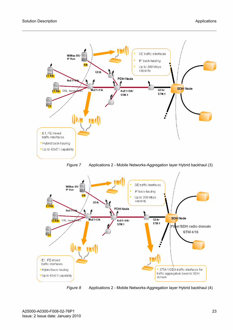
Figure 7 Applications 2 - Mobile Networks-Aggregation layer Hybrid backhaul (3)
Figure 8 Applications 2 - Mobile Networks-Aggregation layer Hybrid backhaul (4)
24 A25000-A0300-F008-02-76P1Issue: 2 Issue date: January 2010
Solution DescriptionApplications
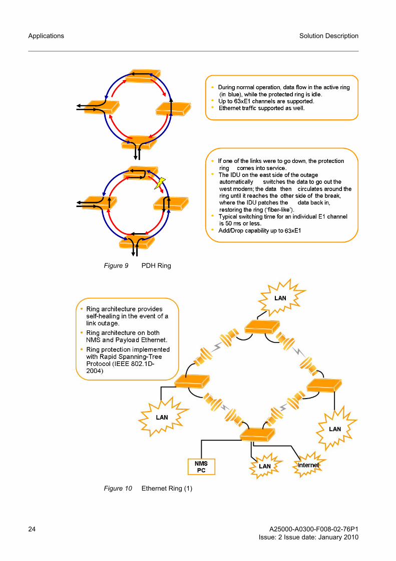
Figure 9 PDH Ring
Figure 10 Ethernet Ring (1)

A25000-A0300-F008-02-76P1Issue: 2 Issue date: January 2010
25
Solution Description Applications
Figure 11 Ethernet Ring (2)
Figure 12 Ethernet Applications

26 A25000-A0300-F008-02-76P1Issue: 2 Issue date: January 2010
Solution DescriptionFeatures
5 Features
5.1 Modulations and capacitiesRegardless of the RF frequency band, the following modulations and channel band-widths are supported:
7 MHz 14 MHz 28 MHz
4 QAM x x x
16 QAM x x x
32 QAM - x x
64 QAM - - x
128 QAM - - x
Table 5 Modulation format supported for each bandwidth
Supported Modes (Minimum SVR#)
Signal BW
(MHz)
Modulation ETSI Equivalent PDH/SDH Rate
RF band (GHz)
6L 6U 7 8 11 13 15 18 23 26 32 38
7 QPSK 8 Mbit/s - - - - - - 2.1 2.1 2.1 - - -
16 QAM 2*8 Mbit/s - - - - - - 2.1 2.1 2.1 - - -
14 QPSK 2*8 Mbit/s - - - - - 1.2 1.1 1.1 1.2 1.3 1.4 1.4
16 QAM 34 Mbit/s - - - - - 1.2 1.1 1.1 1.2 1.3 1.4 1.4
32 QAM STM0 (51) - - - - - 1.2 1.1 1.1 1.2 1.3 1.4 1.4
28 QPSK 34 Mbit/s 1.3 - - - - 1.2 1.1 1.1 1.2 1.3 1.4 1.4
16 QAM 2*34Mbit/s 1.3 - - - - 1.2 1.1 1.1 1.2 1.3 1.4 1.4
32 QAM 2*STM0 1.3 - - - - 1.2 1.1 1.1 1.2 1.3 1.4 1.4
64 QAM 2*STM0/STM1 1.3 1.3 - - - 1.2 1.1 1.1 1.2 1.3 1.4 1.4
128 QAM STM1 1.3 1.3 1.1 1.1 1.1 1.2 1.1 1.1 1.2 1.3 1.4 1.4
Note: “-” = Non-Supported Combinations.
Table 6 Summary of Modes Supported up to SVR 2.1

A25000-A0300-F008-02-76P1Issue: 2 Issue date: January 2010
27
Solution Description Features
The table below shows the data rate (Mbps) by modulation type, channel bandwidth and supported payloads.
ETSI Class
Signal BW
(MHz)
Modulation ETSI Equivalent PDH/SDH Rate
RF band (GHz)
6L 6U 7 8 11 13 15 18 23 26 32 38
7 QPSK 8 Mbit/s - - - - - - 2 2 2 - - -
16 QAM 2*8 Mbit/s - - - - - - 4 4 4 - - -
14 QPSK 2*8 Mbit/s - - - - - 2 2 2 2 2 2 2
16 QAM 34 Mbit/s - - - - - 4 4 4 4 4 4 4
32 QAM STM0 (51) - - - - - 4 4 4 4 4 4 4
28 QPSK 34 Mbit/s 2 - - - - 2 2 2 2 2 2 2
16 QAM 2*34Mbit/s 4 - - - - 4 4 4 4 4 4 4
32 QAM 2*STM0 4 - - - - 4 4 4 4 4 4 4
64 QAM 2*STM0 (*) 4 5B2 - - - 4 4 4 4 4 4 4
128 QAM STM1 (**) 5A2 5B1 5A1 5A1 5B1 5A2 5A1 5A 5A 5A 5A 5A
Note: “-” = Non-Supported Combinations.
(*) The 13 GHz, 15 GHz, 18 GHz and 23 GHz bands were certified with ETSI EN 302 217-2-2 V1.1.3, which admitted for the 28MHz-64QAM modes (RIC equal to 122Mbit/s) the 2xSTM0 equivalent PDH/SDH rate, but not the STM1 equivalent PDH/SDH rate, for which this standard assigns 144 Mbit/s as the minimum RIC. Therefore the class of these modes is Class4. The L6 GHz, 26 GHz, 32 GHz and 38 GHz bands were certified with the new version ETSI EN 302 217-2-2 V1.2.3 (2007-09), which has decreased to 100Mbit/s the minimum RIC required for the STM1 equiv-alent PDH/SDH rate, thus allowing the classes 5A and 5B to be applied to the 28MHz-64QAM modes. However, for uniformity with the other RF bands, class 4 has been maintained.
(**) Because of non-compliance with the Adjacent Interference performance of Class 5B, the Class 5A has been certified for this modes. N.B. the U6 and 11GHz RF band channel step is 40 MHz.
Table 7 Modes and ETSI Class Certification
Row
ID
New
Mod
es N
ame
(BW
.Mod
-#e#
M#s
)
Mod
ulat
ion
Sign
al B
andw
idth
[M
Hz]
Payload Mix
ETSI
Nom
inal
BitR
ate
(Req
)
Min
imum
requ
ired
Lice
nse
Leve
l
Sym
bol R
ate
(Bau
d R
ate)
ba
ud
EMS
[Mbi
t/s]
E1#
Eth
Mbi
t/s
STM
1 #
1 7.4-8M QPSK 7 0 8 0 8 Mbit/s 1 5661915 0.7
2 7.4-2e4M QPSK 7 2 4 0 8 Mbit/s 1 5632914 0.5
Table 8 Modulations, Channel bandwidth and supported payloads

28 A25000-A0300-F008-02-76P1Issue: 2 Issue date: January 2010
Solution DescriptionFeatures
3 7.4-4e QPSK 7 4 0 0 8 Mbit/s 1 5665262 0.5
4 14.4-17M QPSK 14 0 17 0 2*8 Mbit/s 1 11395218 0.8
5 14.4-2e13M QPSK 14 2 13 0 2*8 Mbit/s 1 11399680 0.8
6 14.4-4e9M QPSK 14 4 9 0 2*8 Mbit/s 1 11330523 0.4
7 14.4-8e QPSK 14 8 0 0 2*8 Mbit/s 1 11330523 1.3
8 7.16-17M 16QAM 7 0 17 0 2*8 Mbit/s 1 5670281 0.7
9 7.16-2e13M 16QAM 7 2 13 0 2*8 Mbit/s 1 5629010 0.4
10 7.16-4e9M 16QAM 7 4 9 0 2*8 Mbit/s 1 5665262 0.4
11 7.16-8e 16QAM 7 8 0 0 2*8 Mbit/s 1 5665262 1.3
22 28.4-35M QPSK 28 0 35 0 34 Mbit/s 2 22696741 0.6
23 28.4-2e30M QPSK 28 2 30 0 34 Mbit/s 2 22732434 1.3
24 28.4-4e26M QPSK 28 4 26 0 34 Mbit/s 2 22799360 1.3
25 28.4-8e18M QPSK 28 8 18 0 34 Mbit/s 2 22662162 0.9
26 28.4-16e2M QPSK 28 16 2 0 34 Mbit/s 2 22774821 0.6
27 28.4-18e QPSK 28 18 0 0 34 Mbit/s 2 23843401 0.5
28 14.16-36M 16QAM 14 0 36 0 34 Mbit/s 2 11838043 1.1
29 14.16-2e32M 16QAM 14 2 32 0 34 Mbit/s 2 11865929 0.7
30 14.16-4e28M 16QAM 14 4 28 0 34 Mbit/s 2 11830235 0.6
31 14.16-8e20M 16QAM 14 8 20 0 34 Mbit/s 2 11815735 0.5
32 14.16-16e3M 16QAM 14 16 3 0 34 Mbit/s 2 11859794 1.1
33 14.16-18e 16QAM 14 18 0 0 34 Mbit/s 2 11855314 0.4
49 28.16-74M 16QAM 28 0 74 0 2*34Mbit/s 3 23883557 1.3
50 28.16-2e70M 16QAM 28 2 70 0 2*34Mbit/s 3 23843401 0.5
51 28.16-4e66M 16QAM 28 4 66 0 2*34Mbit/s 3 23843401 0.6
52 28.16-8e57M 16QAM 28 8 57 0 2*34Mbit/s 3 23843401 1.3
53 28.16-16e41M 16QAM 28 16 41 0 2*34Mbit/s 3 23843401 1
54 28.16-18e37M 16QAM 28 18 37 0 2*34Mbit/s 3 23883557 0.7
55 28.16-32e8M 16QAM 28 32 8 0 2*34Mbit/s 3 23843401 1
56 14.32-47M 32QAM 14 0 47 0 STM0 (51) 3 11852978 0.7
Row
ID
New
Mod
es N
ame
(BW
.Mod
-#e#
M#s
)
Mod
ulat
ion
Sign
al B
andw
idth
[M
Hz]
Payload Mix
ETSI
Nom
inal
BitR
ate
(Req
)
Min
imum
requ
ired
Lice
nse
Leve
l
Sym
bol R
ate
(Bau
d R
ate)
ba
ud
EMS
[Mbi
t/s]
E1#
Eth
Mbi
t/s
STM
1 #
Table 8 Modulations, Channel bandwidth and supported payloads (Cont.)

A25000-A0300-F008-02-76P1Issue: 2 Issue date: January 2010
29
Solution Description Features
Row ID:It is the ID assigned to the row and it univocally identifies the mode (License masking is based on this number and link configuration negotiates this number)
57 14.32-2e42M 32QAM 14 2 42 0 STM0 (51) 3 11860786 1.4
58 14.32-4e38M 32QAM 14 4 38 0 STM0 (51) 3 11841266 1.2
59 14.32-8e30M 32QAM 14 8 30 0 STM0 (51) 3 11868594 1
60 14.32-16e14M 32QAM 14 16 14 0 STM0 (51) 3 11868594 0.8
61 14.32-18e10M 32QAM 14 18 10 0 STM0 (51) 3 11850809 0.5
82 28.32-95M 32QAM 28 0 95 0 2*STM0 4 23628743 0.5
83 28.32-2e90M 32QAM 28 2 90 0 2*STM0 4 23574521 0.5
84 28.32-4e86M 32QAM 28 4 86 0 2*STM0 4 23550663 0.5
85 28.32-8e78M 32QAM 28 8 78 0 2*STM0 4 23627442 0.5
86 28.32-16e61M 32QAM 28 16 61 0 2*STM0 4 23625273 1
87 28.32-18e57M 32QAM 28 18 57 0 2*STM0 4 23592740 1
88 28.32-32e29M 32QAM 28 32 29 0 2*STM0 4 23580160 0.4
89 28.32-42e8M 32QAM 28 42 8 0 2*STM0 4 23602283 0.5
119 28.64-16e86M 64QAM 28 16 86 0 STM1 5 24276847 0.5
120 28.64-18e82M 64QAM 28 18 82 0 STM1 5 24252003 0.5
131 28.128-2e144M 128QAM 28 2 144 0 STM1 5 25439742 2
132 28.128-4e136M 128QAM 28 4 136 0 STM1 5 25472695 7
133 28.128-8e128M 128QAM 28 8 128 0 STM1 5 25500000 6.5
134 28.128-16e112M 128QAM 28 16 112 0 STM1 5 25455748 7
135 28.128-18e112M 128QAM 28 18 112 0 STM1 5 25455748 3
136 28.128-32e88M 128QAM 28 32 88 0 STM1 5 25506591 1.3
137 28.128-42e68M 128QAM 28 42 68 0 STM1 5 25500000 1.3
138 28.128-63e26M 128QAM 28 63 26 0 STM1 5 25500000 0.5
139 28.128-1s 128QAM 28 0 0 1 STM1 5 25472382 0.6
140 28.128-P55-100M 128QAM 28 0 55+100 0 STM1 5 25474265 0.5
141 28.128-P78-77M 128QAM 28 0 78+77 0 STM1 5 25500000 0.5
Row
ID
New
Mod
es N
ame
(BW
.Mod
-#e#
M#s
)
Mod
ulat
ion
Sign
al B
andw
idth
[M
Hz]
Payload Mix
ETSI
Nom
inal
BitR
ate
(Req
)
Min
imum
requ
ired
Lice
nse
Leve
l
Sym
bol R
ate
(Bau
d R
ate)
ba
ud
EMS
[Mbi
t/s]
E1#
Eth
Mbi
t/s
STM
1 #
Table 8 Modulations, Channel bandwidth and supported payloads (Cont.)

30 A25000-A0300-F008-02-76P1Issue: 2 Issue date: January 2010
Solution DescriptionFeatures
Mode Name: It it the name of the mode displayed by GUI in the choice list:
<bandwidth>.<modulation>-<number of E1>e<Eth Mbps>M<number of STM1>s
Where:
<bandwidth>= Bandwidth value in MHz
<modulation> = Modulation levels, 4 for QPSK, 16 for 16QAM, etc…
e = short notation for E1
M = short notation for Mbps
s = short notation for STM1
Examples:
• 28.128-8e128M = 28MHz bandwidth, 128QAM that transports 8E1 and 128Mbps of Ethernet payload
• 56.128-16e100M1s = 28MHz bandwidth, 128QAM that transports 16E1, 100Mbps of Ethernet and 1 STM1.
There is one exception: the PLUS modes are named by inserting "Plus" after modula-tion. The "Plus" tag is followed by the Mbps configured for Port1 and Port2 respectively:
<bandwidth>.<modulation>-P<Eth Mbps for Port1>-< Eth Mbps for Port2>M
☞ In the configurations implementing the Gigabit Ethernet Master I/O module (P/N 612-315/10) the PDH capacities higher than 2xE1 need the additional use of the 16xE1 Expansion I/O module (P/N 612-315/05), which requires the 18xE1 mode. No intermediate capacities (example 4xE1, 8xE1 or 16xE1) can be selected.
5.2 Basic configurationsThe available configurations are listed in the following Table 9.
5.2.1 Standard terminalIn this configuration the equipment consists of:
– One ODU– One Antenna– One IDU– One coaxial cable for IDU-ODU interconnection
Type Description Channeling
1 1+0 (standard) terminal AP
2 1+1 protected diversity terminal AP
3 1+1 protected non diversity terminal (Hot Standby) AP
4 East-East (2+0 same destination) AP
5 East-West (2+0 different destination or Ring) AP
Table 9 Configurations

A25000-A0300-F008-02-76P1Issue: 2 Issue date: January 2010
31
Solution Description Features
Figure 13 1+0 (Standard) terminal
5.2.2 Protected terminalThe equipment consists of:
– Two ODUs– One or two antennas– One IDU– One coaxial cable for each IDU-ODU interconnection
Following options are available for protected configuration:
– Hot Stand-by– Frequency Diversity– Space diversity
With two modems and two power supplies installed, the “FlexiHybrid” can also support 1+1 protection in a single 1 RU chassis as an option for a critical link.
The “FlexiHybrid” contains two power supplies and two modems. The power supply, ODU, IF/telemetry and modem are protected. The digital framing and LIUs are not. One modem is referred to as the west modem and the other as the east modem. 1+1 protec-tion can be run in two modes: Protected Non-Diversity and Protected Diversity.
1+1 protected diversityIn this case the link between each pair of modems is the same, providing complete redundancy.
This arrangement requires bandwidth for both links and non-interference between the links, but it provides hitless Rx and Tx switching.
The IDU supports both frequency and spatial diversity.
• Frequency diversity: two frequencies are used • Spatial diversity: one transmitter and two receivers (one in standby). Two non-inter-
fering paths are used
In either case, the proprietary framer chooses the best, or error-free, data stream and forwards it to the Line Interface Units (LIUs).

32 A25000-A0300-F008-02-76P1Issue: 2 Issue date: January 2010
Solution DescriptionFeatures
A 1+0 link may be provided as 1+1 link, allowing the standby MODEM and Power-Supply to be installed at a later date. Once installed, 1+1 protection will immediately be available.
In the Protected Diversity mode, the link between each pair of modems is the same, as shown in Figure 14, providing complete redundancy. This arrangement requires band-width for both links and non-interference between the links, but it provides hitless receive and transmit switching.
The “FlexiHybrid” supports both frequency and spatial diversity.
Figure 14 1+1 protected diversity mode
Frequency DiversityIn frequency diversity, two frequencies are used to achieve non-interference. The pro-prietary framer chooses the best, or error-free, data stream and forwards it to the Line Interface Units (LIUs).
Spatial DiversityIn spatial diversity, two non-interfering paths are used. The proprietary framer chooses the best, or error-free, data stream and forwards it to the Line Interface Units (LIUs).
• Single Transmitter: Protected Non-Diversity, or Hot Standby, is also refered to as Single Transmitter Spatial Diversity.
• Dual Transmitter:When using Dual Transmitter Spatial Diversity, two active transmitters are physically isolated toavoid crosstalk.
Protected Non-Diversity (Hot Standby)Figure 15 shows operation in the Protected Non-Diversity mode, also called Hot Standby. In this mode, one ODU at each location transmits to two ODUs at the other location. This mode does not require the extra bandwidth or interference protection. It provides hitless receive switching and hot standby. “FlexiHybrid” automatically switches transmit ODU upon appropriate ODU alarm or ODU interface error, minimizing transmit outage time.

A25000-A0300-F008-02-76P1Issue: 2 Issue date: January 2010
33
Solution Description Features
Figure 15 1+1 protection in non-diversity mode
In this case one ODU at each location transmits to both two ODUs at the other location.
This arrangement does not require the extra bandwidth or interference protection of diversity mode and provides hitless receive switching and hot standby.
IDU automatically switches transmit ODU upon appropriate ODU alarm or ODU inter-face error, minimizing transmit outage time.
The power supply, ODU, IF/telemetry and modem are protected.
The digital framing and LIUs are not protected.
A 1+0 link may be provided as 1+1 link, allowing the standby MODEM and Power-Supply to be installed at a later date. Once installed, 1+1 protection will be immediately available.
The received signals are separately decoded, and a switch operating at base band level selects one of the two data streams.

34 A25000-A0300-F008-02-76P1Issue: 2 Issue date: January 2010
Solution DescriptionFeatures
5.2.3 Ring configuration (East-West)RING system type is characterized by two different radio directions and it employs two ODUs.
Ring configuration creates a self-healing redundancy that is more reliable than tradi-tional point-to-point networks.
Protection consists of two paths through the ring, the Active path (blue) and the Stand-by path (red). In case of outage, traffic is automatically rerouted from the Active to the Stand-by path on either side of the outage, thus recovering service interruption.
Figure 16 Ring
Ring configuration can be used to protect E1 circuits, as well as Ethernet payload.

A25000-A0300-F008-02-76P1Issue: 2 Issue date: January 2010
35
Solution Description Features
5.3 Equipment compositionTable 10 below shows the composition of the equipment and it is used to transmit in all the available bands.
g Note 1: To interface the E1 tributaries between the FlexiHybrid and the station equipment are available the patch panels to be installed in the same ETSI rack.
g Note 2: The type of waveguide connection between the ODU and the antenna can be either flexible or elliptical.
g Note 3: The coupler can be balanced or unbalanced.
Indoor Section Outdoor Assembly
ETSI Rack
IDU Assembly
Patch panels
6L GHz
6U GHz
7 GHz
8 GHz
11 GHz
13 GHz
15 GHz
18 GHz
23 GHz
26 GHz
32 GHz
38 GHz
HC AP/CC
HC AP/CC
HC AP/CC
HC AP/CC
HC AP/CC
HC AP/CC
HC AP/CC
HC AP/CC
HC AP/CC
HC AP/CC
HC AP
HC AP
Table 10 Equipment composition
Configuration Name Ref. to Figure
1+0 1+0 system with integrated antenna Figure 17
1+0 system with independent antenna Figure 18
1+1 HSBY/FD 1+1 system with Hot Standby or FD with integrated antenna Figure 19
1+1 system with Hot Standby or FD with independent antenna Figure 20
1+1 DP 1+1 system with dual polarization with adjacent channels Figure 21
1+1 SD 1+1 spatial diversity system with two independent antennas Figure 22
East-West 2+0 system with different destinations or Ring with integrated antennas Figure 23
Table 11 Equipment composition according to the configuration

36 A25000-A0300-F008-02-76P1Issue: 2 Issue date: January 2010
Solution DescriptionFeatures
Figure 17 1+0 system with integrated antenna
INTEGRATED ANTENNA30 cm or 60 cm
COAXIAL CABLE
ETSI RACK (19”)
IDU
HC AP/CC ODU
HC AP ODU

A25000-A0300-F008-02-76P1Issue: 2 Issue date: January 2010
37
Solution Description Features
Figure 18 1+0 system with independent antenna
COAXIAL CABLE
ODU FRAME
FLEXIBLEWAVEGUIDE
ETSI RACK (19”)
IDU
HC AP ODU
HC AP/CC ODU

38 A25000-A0300-F008-02-76P1Issue: 2 Issue date: January 2010
Solution DescriptionFeatures
Figure 19 1+1 system with Hot Standby or FD with integrated antenna
COAXIAL CABLE
1+1 INTEGRATED SUPPORTING FRAME
HC AP/CC ODU
ETSI RACK (19")
IDU
HC AP ODU

A25000-A0300-F008-02-76P1Issue: 2 Issue date: January 2010
39
Solution Description Features
Figure 20 1+1 system Hot Standby or FD with independent antenna
COAXIAL CABLE
ETSI RACK (19”)
1+1 FRAME
FLEXIBLEWAVEGUIDE
HC AP/CC ODU
IDU
HC AP ODU
40 A25000-A0300-F008-02-76P1Issue: 2 Issue date: January 2010
Solution DescriptionFeatures
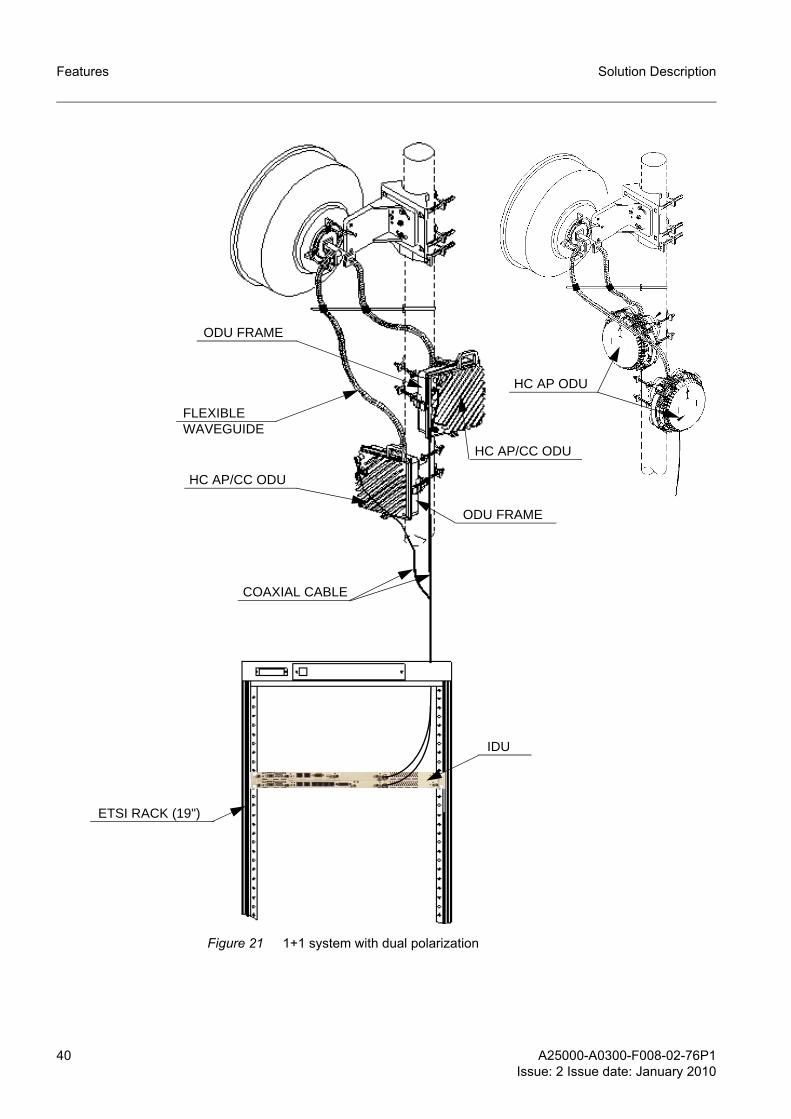
Figure 21 1+1 system with dual polarization
ODU FRAME
FLEXIBLEWAVEGUIDE
HC AP/CC ODU
COAXIAL CABLE
ODU FRAME
HC AP/CC ODU
HC AP ODU
ETSI RACK (19")
IDU

A25000-A0300-F008-02-76P1Issue: 2 Issue date: January 2010
41
Solution Description Features
Figure 22 1+1 SD system with two separated antennas
ODU FRAME
FLEXIBLEWAVEGUIDE
COAXIAL CABLE
HC AP/CC ODU
HC AP ODU
ETSI RACK (19")
IDU
HC AP ODU
HC AP/CC ODU
ODU FRAME
FLEXIBLEWAVEGUIDE

42 A25000-A0300-F008-02-76P1Issue: 2 Issue date: January 2010
Solution DescriptionFeatures
Figure 23 East-West (2+0 system with different destinations or Ring) with integrated antennas
COAXIAL CABLE
INTEGRATED ANTENNA30 cm or 60 cm
HC AP/CC ODU
HC AP/CC ODU
ETSI RACK (19”)
IDU
INTEGRATED ANTENNA30 cm or 60 cm
HC AP ODU

A25000-A0300-F008-02-76P1Issue: 2 Issue date: January 2010
43
Solution Description Features
5.4 Link Terminals with different configurationA link composed of two IDUs equipped with different HW modules can be setup (this link is called Mixed Link). This type of link allows using different payload interfaces for the two network elements (for example, STM1 interface in one terminal and 32 E1 interface in the other one).
Figure 24 Link terminals with different configuration
A mixed link is ensured by the fact that the configurations of the two terminals are over the air compatible. This requires that the following conditions are met:
1. The two modems are configured with compatible Modes files: the same RowIDs contain the same configuration for modem and payload parameters (and obviously the same mode is selected).
2. The Master IO modules of the IDUs have compatible framer structure.
Table 12 and Table 13 summarize the master IO modules with the over the air compat-ibility (starting from the SVR this is ensured).
Master Module equipped in IDU 2
Stan
dard
M
aste
r I/O
Enha
nced
M
aste
r I/O
42E1
M
aste
r I/O
Gig
E M
aste
r I/O
Stan
dard
2 M
aste
r I/O
Enha
nced
2 M
aste
r I/O
EnhG
igE
Mas
ter I
/O
Mas
ter M
odul
e eq
uipp
ed in
IDU
1
Standard Master I/O
From SVR 1.0
- - - - - -
Enhanced Master I/O
From SVR 1.0
From SVR 1.1
- - - - -
42E1 Master I/O
From SVR 1.2
From SVR 1.2
From SVR 1.2
- - - -
GigE Master I/O
From SVR 1.2
From SVR 1.2
From SVR 1.2
From SVR 1.1
- - -
Standard2 Master I/O
From SVR 2.1
From SVR 2.1
From SVR 2.1
From SVR 2.0
From SVR 2.0
- -
Enhanced2 Master I/O
From SVR 2.1
From SVR 2.1
From SVR 2.1
From SVR 2.0
From SVR 2.0
From SVR 2.0
-
EnhGigE Master I/O
From SVR 2.1
From SVR 2.1
From SVR 2.1
From SVR 2.0
From SVR 2.1
From SVR 2.1
From SVR 2.1
Table 12 Over the air compatibility for Master IO modules (link terminals are intended to have the same SVR)

44 A25000-A0300-F008-02-76P1Issue: 2 Issue date: January 2010
Solution DescriptionFeatures
☞ Table 13 summarizes which SVRs are over the air compatible. Note that it describes cases where different SVRs are loaded on the two link terminals. Although this con-dition is not supported as standard working condition it shall be considered during SVR upgrade phase, mostly if the upgrade is performed from remote site.
5.5 Ethernet payload ProcessingThe characteristics of Ethernet payload processing and features strictly depend on the equipped Master IO Module type.
There are seven types of Master IO:
– Standard Master IO– Standard2 Master IO– Enhanced Standard Master IO with STM-1 – Enhanced2 Standard Master IO with STM-1 – GE Master IO– GE Enhanced Master IO– 42xE1 Master IO
Standard/Standard2 Master IO/Enhanced/Enhanced2 Standard Master IO and 42xE1 Master IO support FE up to 100 Mbps.
GE Master IO supports GE up to 155Mbps.
5.5.1 Maximum bit rate over the air
A) Standard/Standard2 Master IO / Enhanced/Enhanced2 Master IO / 42xE1 Master IO characteristics
SVR loaded in IDU 2
SVR 1.0 SVR 1.1 SVR 1.2 SVR 1.3 SVR 1.4 SVR 2.0 SVR 2.1
SVR loaded in IDU 1
SVR 1.0 Yes - - - - - -
SVR 1.1 No Yes - - - - -
SVR 1.2 No No Yes - - - -
SVR 1.3 No No Yes Yes - - -
SVR 1.4 No No No Yes Ye - -
SVR 2.0 No No No No Yes Yes -
SVR 2.1 No No No No Yes Yes Yes
Table 13 Over the air compatibility for Master IO modules (link terminals are intended to have the same SVR)
They have 2 E/FE interfaces and the maximum supported rate over the air is up to 100Mbps for each radio interface 1)
1) The limitation to 100Mbps radio-side is determined by the framer capacity used in this module

A25000-A0300-F008-02-76P1Issue: 2 Issue date: January 2010
45
Solution Description Features
Payload rate can be increased up to 155Mbps by configuring the "Plus" mode (78 Mbps for Ethernet port 1 + 77 Mbps for Ethernet port 2 or 55 Mbps for Ethernet port 1 + 100 Mbps for Ethernet port 2): in this mode Ethernet payload rates of 155 Mbps can be achieved by utilizing both 100Base-TX front panel payload ports. In this configuration, two Ethernet channels are provided in the payload frame using internal Port-based VLAN (not accessible or configurable by the user).
The max traffic rate for each Ethernet channel to the framer is defined in the modes file. A user is not allowed to use these modes in a 2+0 configuration.
Two applications are possible:
• two-network operation • single-network operation (this does not correspond to a different IDU configuration
but it is based on the usage of an external router).
Single Network Operation This configuration is considered with an external router in mind. This configuration is really an extension of the mode described above. There are no changes in the program-ming or operation of the IDU. This mode allows a user to transmit data from a single network at a rate greater than 100 Mbps. The external router is required to handle the management of the trunk. The router must ensure that the same MAC address is not delivered to both front panel ports. The setup for single network operation is shown in Figure 25.
Figure 25 Single Network Operation

46 A25000-A0300-F008-02-76P1Issue: 2 Issue date: January 2010
Solution DescriptionFeatures
Two-Network OperationThis mode allows the operator to provide access to two separate Fast Ethernet users, and guarantee the throughput level for each. Different rates for each port are supported, as configured in the modes file. In this mode, each channel operates as a single channel would in a single port mode. The setup for two-network operation is shown in Figure 26.
Figure 26 Two-Network Operation
B) GigEth and GigEth Enhanced Master IO characteristics:
This module has 4 10/100/1000 Mbps electrical Ethernet ports + 1 GigaEthernet SFP. The maximum supported payload rate over the air is 300Mbps for each radio interface 1)
1) From SVR 1.1 the widest supported signal bandwidth is 28MHz, therefore the 300Mbps cannot be reached even when the 128QAM modulation is used.

A25000-A0300-F008-02-76P1Issue: 2 Issue date: January 2010
47
Solution Description Features
There is the possibility to increase the payload rate up to 155 Mbps by configuring the “Plus” mode (78 Mbps for Ethernet ports 1 and 2 + 77 Mbps for Ethernet ports 3 and 4 or 55 Mbps for Ethernet ports 1 and 2 + 100 Mbps for Ethernet ports 3 and 4. The SFP can be associated to the first port group or to the second port group): in this mode Ethernet payload rates of 155 Mbps may be achieved by utilizing the front panel payload ports. In this configuration, two Ethernet channels are provisioned in the payload frame and are associated to each interface.
The max traffic rate for each Ethernet channel to the framer is defined in the modes file. The available Plus modes contains rate up to 155Mbps. A user cannot use Plus modes in a 2+0 (East/West) configuration.

48 A25000-A0300-F008-02-76P1Issue: 2 Issue date: January 2010
Solution DescriptionFeatures
5.5.2 Port SettingAutonegotiation is supported for each interface. It can be Enabled and Disabled by the user.
When disabled the following parameters can be set by the user:
– Port Speed: For Standard/Standard2/Enhanced/Enhanced2/42xE1 Master IO the possible values are 10 or 100Mbps. For GigEth Master Io the possible values are 10, 100 or 1000Mbps.
– Port Duplex: possible values are Half and Full
When enabled the parameters value after the autonegotiation procedure is not available via WEB-LCT.
Flow Control is supported; it can be configured as Disabled or Symmetric (Enable). When enabled the IDU slows the egress from the Ethernet switch which will initiate flow-control via the front-panel ports. The scaling of Ethernet traffic will in effect limit the front-panel egress rate on the far end of the link. Flow control is supported in both full-duplex and half-duplex. Full-Duplex is implemented with respect for PAUSE packets as well as generation of PAUSE packets. Half-Duplex is implemented with back-pressure.
Ingress rate-limiting per front-panel port is not supported.
Master-Slave mode for clock is supported (in GigEth and GigEth Enhanced Master IO); it can be configured as Auto, Slave or Master mode.
The possibility to Disable the Ethernet ports is not supported.
5.5.3 Learning functionalityThe MAC DB can learn up to 4096 MAC Addresses. When the MAC table is full, the swith is blocked (no transmission).
Static entries cannot be added and the MAC DB table is not available for the user (debug or standard usage).
5.5.4 Forwarding functionalityThe forwarding scheme is always "fully connected ports" and it is not possible to config-ure different forwarding schemes.
5.5.5 Ethernet Latency
Packet size Minimum Latency (mS ) (64 bytes)
MaximumLatency(mS) (1518 bytes)
10 3.25 4.65
70 0.52 0.92
100 0.37 0.73
Table 14 Standard and Enhanced Master I/O Card

A25000-A0300-F008-02-76P1Issue: 2 Issue date: January 2010
49
Solution Description Features
5.5.6 VLAN management and Max packet sizeVLAN tagging or Port-based VLAN configuration are not supported. VLAN tagged packets are passed through without modification.
The maximum packet size depends on the module type:
Standard and Enhanced Master I/O card: Max packet size is 1536 bytes.
Standard2 and Enhanced2 Master I/O card: Max packet size is 2048 bytes.
The Port based VLANs are supported, but not user-configurable as they are internally managed in order to implement 155FE in Plus modes.
GigEth Master IO card: Max packet size is 4000 bytes.
In GigEth modules as weel as the Port-Based VLANs is internally managed to segregate overall bandwidth into two independent Ethernet networks when Plus modes are config-ured.
42xE1 Master IO card: Max packet size is 2048 bytes.
VLAN tagging or Port-based VLAN configuration are not supported. VLAN tagged packets are passed through without modification.
5.5.7 Buffer sizeEthernet Buffer (Standard IO modules and Enhanced IO module)
Packet size Minimum Latency (mS ) (64 bytes)
MaximumLatency(mS) (1518 bytes)
10 3.29 4.60
50 0.72 1.09
100 0.42 0.68
150 0.26 0.37
200 0.19 0.28
Table 15 Gigabit Master I/O Card
Packet size Avarage Latency(µs)
64 430.2
128 451.7
256 493.1
512 574.6
1024 738.1
1280 820.2
1518 896.9
Table 16 42xE1Master I/O Card

50 A25000-A0300-F008-02-76P1Issue: 2 Issue date: January 2010
Solution DescriptionFeatures
– Layer 2 Ethernet switch contains 160 Kbytes of buffer– Divided into 640 blocks of 256 bytes– Blocks are dynamically allocated
Ethernet Buffer (GigEth Master IO module)
– Layer 2 Ethernet switch contains 128 Kbytes of buffer– Divided into 512 blocks of 256 bytes– Blocks are dynamically allocated
Ethernet Buffer (42xE1 Master IO module)
– Total on-chip memory in Ethernet switch is 64 Kbyte
5.5.8 Counters, Link monitoringLink capacity is not variable and link capacity monitoring is not available. Packet moni-toring is provided in the form of Ethernet switch statistics (i.e. Tx Packets, Tx Bytes, Tx Errors, Rx Packets, Rx Bytes, Rx Errors).
Link Loss Failure (LLF) not supported.
5.5.9 QoS
5.5.9.1 QoS in Standard and Enhanced Master IO modules
Priority Assignment: For each frame entering the Ethernet user interface (Port1 or Port2) the following priority criterias are applied:
– Port-based– 802.1Q VLAN TAG priority– IPv4 ToS priority (first 3 bits of the DiffServ field)
Each criteria can be Enabled and Disabled (global setting) and the user can select which QoS criteria shall be resolved first (Priority Resolution configuration).
The Ethernet switch used on the Standard and Enhanced Master IO Module provides 2 switch priority levels (0-lowest, 1-highest). Each criterion can be assigned to one Switch Priority (refer to Figure 27).
Output queues:The radio port contains two independent output queues (High and Low).
Weighted Fair Queue ratios are fixed for 802.1Q VLAN TAG priority and for IPv4 TOS (even though they are selectable via the Web GUI).

A25000-A0300-F008-02-76P1Issue: 2 Issue date: January 2010
51
Solution Description Features
Figure 27 Priority assignment logic scheme (Standard and Enhanced Master IO Modules)
5.5.9.2 QoS in Standard2, Enhanced2 and 42xE1 Master IO modules
Priority Assignment: For each frame entering the Ethernet user interfaces (Port1 and Port2) the following priority criteria are applied:
– Port-based– 802.1Q VLAN TAG priority– DiffServ priority
Each criterion can be Enabled or Disabled (global setting) with the following constraints:
– When Port-based is Enabled the other two criteria are automatically set to Disabled
– When Port-based is Disabled the other two criteria can be Enabled or Disabled (separately or both at the same time).
When 802.1Q and DiffServ priorities are Enabled, the user can select which QoS crite-rion shall be resolved first (Priority Resolution configuration) between 802.1Q VLAN and DiffServ priority.
Each frame entering the Ethernet user interface can be associated to one Tx output queue (refer to Figure 28).

52 A25000-A0300-F008-02-76P1Issue: 2 Issue date: January 2010
Solution DescriptionFeatures
Output queues:The Radio port (that is the internal switch interfaces connected to the Radio link) contains four independent output queues. The order the frames are transmitted out each port depends on the scheduling mode.
The unit supports:
– Weighted Fair Queuing (WFQ) scheduling modes with fixed weights 8, 4, 2, 1 (the user cannot configure them).
– Strict Priority Scheme: the Preemption of highest priority queue is available . It can be enabled or disabled by the user; when the Preemption is enabled the highest priority queue is serviced until it is empty before servicing lower priority queues.
Figure 28 Priority assignment logic scheme
5.5.9.3 QoS in GigEth and GigEth Enhanced Master IO module
Priority Assignment: For each frame entering the Ethernet user interfaces (Port1, Port2, Port3, Port4 and SFP) the following priority criteria are applied:
– Port-base– 802.1Q VLAN TAG priority– DiffServ priority
Each criterion can be wholly enabled or disabled. It is not possible to enable or disable the criteria on a per port-base.
When multiple priority schemes are enabled, the priority, determined for a specific packet, will be the highest available priority.
A25000-A0300-F008-02-76P1Issue: 2 Issue date: January 2010
53
Solution Description Features
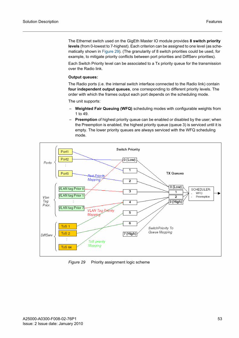
The Ethernet switch used on the GigEth Master IO module provides 8 switch priority levels (from 0-lowest to 7-highest). Each criterion can be assigned to one level (as sche-matically shown in Figure 29). (The granularity of 8 switch priorities could be used, for example, to mitigate priority conflicts between port priorities and DiffServ priorities).
Each Switch Priority level can be associated to a Tx priority queue for the transmission over the Radio link.
Output queues:The Radio ports (i.e. the internal switch interface connected to the Radio link) contain four independent output queues, one corresponding to different priority levels. The order with which the frames output each port depends on the scheduling mode.
The unit supports:
– Weighted Fair Queuing (WFQ) scheduling modes with configurable weights from 1 to 49.
– Preemption of highest priority queue can be enabled or disabled by the user; when the Preemption is enabled, the highest priority queue (queue 3) is serviced until it is empty. The lower priority queues are always serviced with the WFQ scheduling mode.
Figure 29 Priority assignment logic scheme

54 A25000-A0300-F008-02-76P1Issue: 2 Issue date: January 2010
Solution DescriptionFeatures
5.6 Ethernet payload Processing in Standard2 and Enhanced2 Master IO Modules☞ The Ethernet payload processing of the Enhanced GigaE Master IO Module is the
same of the GigaE Master IO Module.
The characteristics of Ethernet payload processing and features strictly depend on the equipped Master IO Module type. Standard2 and Enhanced2 Modules employ the same Ethernet switch and the same Ethernet payload processing as the 42E1 Master IO Module. For better readability, the Ethernet processing of the new modules is reported here, highlighting the differences from the Standard and Enhanced Master IO modules.
☞ If not explicitly stated, the features described in the next subsections for the Standard2 and Enhanced2 Master IO Modules are the same as the Standard and Enhanced Master IO Modules.
5.6.1 Maximum Bit-Rate Over The AirThe Standard2 and Enhanced2 Master IO Modules have 2 E/FE interfaces and the maximum supported rate over the air is up to 100 Mbit/s for each radio interface.There is the possibility to increase the payload rate up to 200 Mbit/s by configuring the "Plus" mode: in this mode Ethernet payload rates over 100 Mbit/s (such as 200 Mbit/s) may be achieved by utilizing both 100Base-TX front panel payload ports. In this configuration, two Ethernet channels are provisioned in the payload frame and are associated to each interface.The max traffic rate for each Ethernet channel to the framer is defined in the modes file.
A user is not permitted to use Plus modes in a 2+0 (East/West) configuration.
5.6.2 Port SettingAutonegotiation is supported for each interface. It can be Enabled and Disabled by the user.
When disabled the following parameters can be set by the user:
– Port Speed: the possible values are 10 or 100 Mbit/s. – Port Duplex: possible values are Half and Full
When enabled the parameter value after the autonegotiation procedure is not available via WEB-LCT.
Flow Control is supported in both full-duplex and half-duplex and is user configurable. Full-Duplex is implemented with respect for PAUSE packets as well as generation of PAUSE packets. Half-Duplex is implemented with back-pressure.
Ingress rate-limiting per front-panel port is not supported.
The possibility to disable the Ethernet ports is not supported.
Shut down port in Link failureWhen this is enabled, the output of Ethernet port is shut down if the radio link is down. After the restoring of the radio link the Ethernet port is automatically activated. It can be enabled or disabled by the user on per port basis (It is supported for all the master mod-ules).

A25000-A0300-F008-02-76P1Issue: 2 Issue date: January 2010
55
Solution Description Features
5.6.3 Learning FunctionalityWithin the Standard2 and Enhanced2 Ethernet switch, the MAC DB can learn up to 1024 MAC Addresses, as in 42E1 Master IO Module, while both the Standard and Enhanced allowed up to 4096 MAC addresses in their MAC database.
It is not possible to add static entries and the MAC table is not available for the user.
Ageing time is not configurable and is fixed to 300 seconds.
5.6.4 Forwarding FunctionalityThe forwarding scheme is always "fully connected ports" and it is not possible to config-ure different forwarding schemes.
5.6.5 VLAN Management and Maximum Packet SizeVLAN tagging or Port-based VLAN configuration is not supported. VLAN tagged packets are passed through without modification.
In the Standard2 and Enhanced2 Modules the maximum packet size is 2048 bytes; while in the Standard and Enhanced version, the maximum packet size is 1536 bytes. For fast comparison, see also the summary section 5.7.
5.6.6 Throughput, Latency, and Back-to-Back LimitsThe following tables contain the throughput, latency and back-to-back limits related to the Fast Ethernet ports of the Standard2 and Enhanced2 IO Modules in case of error-free radio channel (the same values apply also to the 42E1 Master IO module but not to former Standard and Enhanced modules). These values do not depend on the overall radio capacity, but to the capacity reserved to the Ethernet traffic.
Throughput [%]1)
Frame Size (bytes)
Ethernet Capacity
8 Mbit/s 26 Mbit/s 82 Mbit/s
64 10.63 33.20 99.41
128 9.38 30.02 93.38
256 8.75 28.13 87.62
512 8.75 27.51 85.05
1024 8.12 26.86 83.79
1280 8.11 26.86 83.15
1518 8.11 26.86 83.18
2048 8.31 27.5 83.13
Table 17 Throughput on Standard2 and Enhanced2 IO Modules (%)

56 A25000-A0300-F008-02-76P1Issue: 2 Issue date: January 2010
Solution DescriptionFeatures
1) The throughput values are based on the percentage of total line utilization which includes the Preamble (7 octets), Start of Frame Delimiter (SFD) (1 octet), Frame Check Sequence (FCS) (4 octets) and Inter Packet Gap (IPG) (12 octets). The frame size shown in the leftmost column includes the FCS, but excludes the Preamble, SFD and IPG (20 octets total).
Throughput [Mbit/s]1)
1) The throughput values are based on the percentage of total line utilization which includes the Preamble (7 octets), Start of Frame Delimiter (SFD) (1 octet), Frame Check Sequence (FCS) (4 octets) and Inter Packet Gap (IPG) (12 octets). The frame size shown in the leftmost column includes the FCS, but excludes the Preamble, SFD and IPG (20 octets total).
Frame Size (bytes)
Ethernet Capacity
8 Mbit/s 26 Mbit/s 82 Mbit/s
64 8.1 25.3 75.7
128 8.1 26.0 80.8
256 8.1 26.1 81.3
512 8.4 26.5 81.9
1024 8.0 26.3 82.2
1280 8.0 26.4 81.9
1518 8.0 26.5 82.1
2048 8.2 27.2 82.3
Table 18 Throughput on Standard2 and Enhanced2 IO Modules (Mbit/s)
Average Latency [µs]
Frame Size (bytes)
Ethernet Capacity
8 Mbit/s 26 Mbit/s 82 Mbit/s
64 560.2 301.6 334.4
128 638.4 334.5 354.7
256 785.0 403.8 399.5
512 1084.5 544.2 487.3
1024 1700.1 820.4 658.0
1280 1986.8 961.1 746.4
1518 2269.4 1094.2 826.5
2048 2903.2 1375.7 1002.5
Table 19 Latency on Standard2 and Enhanced2 IO Modules

A25000-A0300-F008-02-76P1Issue: 2 Issue date: January 2010
57
Solution Description Features
5.6.7 Buffer sizeEthernet Buffer in Standard2 and Enhanced2 Master Modules: total on-chip memory in Ethernet switch is 64 Kbyte. In Standard and Enhanced the buffer size is 160 Kbyte.
5.6.8 Counters, Link monitoringPacket monitoring is provided in the form of Ethernet switch statistics (i.e. Tx Packets, Tx Bytes, Tx Errors, Rx Packets, Rx Bytes, Rx Errors).
5.6.9 QoSIn FlexiHybrid IDU the priority assignment criteria and output queue management depends on the Master IO module type. In the following the implementation of Standard2 and Enhanced2 Modules is described (the same behaviour as the 42E1 Master IO Module but different from Standard and Enhanced modules: see below).
Priority AssignmentFor each frame entering the Ethernet user interfaces the following priority criteria are applied:
– Port-based– 802.1Q VLAN priority– DiffServ priority
Each criterion can be Enabled or Disabled (global setting) with the following constraints:
– When Port-based is Enabled the other two criteria are automatically reset to Dis-abled;
– When Port-based is Disabled the other two criteria can be Enabled or Disabled (sep-arately or both at the same time).
Frame Size (bytes)
Ethernet Capacity
8 Mbit/s 26 Mbit/s 82 Mbit/s
64 99 130 1270926
128 73 87 663
256 59 80 390
512 51 63 318
1024 27 35 139
1280 18 23 81
1518 18 22 87
2048 12 16 59
Table 20 Back-to-back frames limits on Standard2 and Enhanced2 IO Modules

58 A25000-A0300-F008-02-76P1Issue: 2 Issue date: January 2010
Solution DescriptionFeatures
When 802.1Q and DiffServ priority are Enabled, the user can select which QoS criterion shall be resolved first (Priority Resolution configuration) between 802.1Q VLAN and DiffServ priority.
Each criterion can be assigned to one Tx priority queue for the transmission over the Radio link.
Output queuesIn Standard2 and Enhanced2 modules the Radio ports (that is the internal switch inter-faces connected to the Radio link) contain four independent output queues. The order the frames are transmitted out each port depends from the scheduling mode.
The unit supports the Weighted Fair Queuing (WFQ) scheduling mode, with the fixed weights 8, 4, 2, 1 (the user can not configure them).
Differences with the Standard and Enhanced ModulesPrevious Standard and Enhanced Modules support two switch priority levels (0-lowest, 1-highest), corresponding to two output queues (High and Low); the global configuration "Priority Queue Ratio" allows setting "High:Low" queue ratio packets to be processed. The possible values are 1:2, 1:4, 1:8 and 1:16.
Moreover, previous Standard and Enhanced Modules support the IPv4-ToS priority assignment criterion instead of the DiffServ criterion.

A25000-A0300-F008-02-76P1Issue: 2 Issue date: January 2010
59
Solution Description Features
5.7 Ethernet Functionality SummaryThis section intends to summarise the characteristics of the Master IO Modules with respect to the Ethernet payload processing.
Master IO Module Standard Enhanced Standard2 Enhanced2 GigE Enhanced GigE
42E1
User Ports 2 E/FE 2 E/FE 2 E/FE 2 E/FE 4 E/FE/GigE + 1 GigE SFP (el/opt)
4 E/FE/GigE + 1 GigE SFP (el/opt)
2 E/FE
Max Capacity Radio Ports1)
100 Mbit/s
100 Mbit/s 100 Mbit/s 100 Mbit/s 300 Mbit/s 300 Mbit/s 100 Mbit/s
Buffer Size 160 kbytes
160 kbytes 64 kbytes 64 kbytes 128 kbytes 128 kbytes 64 kbytes
Max Packet size 1536 bytes
1536 bytes
2048 bytes 2048 bytes 4000 bytes 4000 bytes 2048 bytes
MAC DB dimension [entry #]
4096 4096 1024 1024 4096 4096 1024
Ageing Time 300 s 300 s 300 s 300 s 300 s 300 s 300 s
Output Queues 2) 2 2 4 4 4 4 4
Scheduling WFQ WFQ WFQ/strictly
WFQ/strictly
WFQ / Pre-empt
WFQ / Pre-empt
WFQ/strictly
Port Based Priority Yes Yes Yes Yes Yes Yes Yes
802.1Q VLAN Priority Yes Yes Yes Yes Yes Yes Yes
IPv4 ToS Priority Yes Yes Yes 3) Yes 3) Yes 3) Yes 3) Yes 3)
DiffServ Priority No No Yes Yes Yes Yes Yes
Plus Modes (in 1+0/1+1)
Yes Yes Yes Yes Yes 4) Yes 4) Yes
2+0 East/West Seg-regated
Yes Yes Yes Yes Yes Yes Yes
2+0 East/East Trunked
No No No No Yes Yes No
2+0 East/East Segre-gated
No No No No Yes Yes No
Shut down port in Link failure
Yes Yes Yes Yes Yes Yes Yes
Support of Rapid STP Yes Yes Yes Yes Yes Yes Yes
Table 21 Summary of Ethernet Characteristics1) Capacity of the Radio Ports of the Ethernet switch. For the Ethernet over-the-air capacity see modes file.2) Only on radio ports.3) IPv4 TOS can be emulated by using DiffServ.4) Plus modes supported for capacity lower or equal to 100 Mbit/s per VLAN port group (ports 1&2 and ports 3&4).

60 A25000-A0300-F008-02-76P1Issue: 2 Issue date: January 2010
Solution DescriptionFeatures
5.8 Spanning TreeThe Rapid Spanning Tree protocol for Ethernet payload is supported. It can be Enabled and Disabled by the user and the following parameters can be configured:
Bridge Priority, Hello Time, Max Age and Forward Delay.
5.9 100Mbps-PLUS EthernetEthernet payload rates over 100 Mbps (155 Mbps) may be achieved by utilizing the front panel payload ports. In this configuration, two Ethernet channels are provided in the payload frame. The max traffic rate for each Ethernet channel to the framer is defined in the modes file.
5.10 APC (Adaptive Power Control)The Adaptive Power Control capability reduces interference in densely deployed net-works.
The Adaptive Power Control algorithm lowers the Tx Power to between the 1E-6 and 1E-12 BER rate level.
If SNR or signal-level decreases, the Tx Power is increased to maintain the 1E-6 BER.
Alarms are raised if maximum Tx Power is reached.
The implementation of ATPC loop is described by the following block diagram of receiv-ing and transmitting side (see Figure 30 and Figure 31 where CER means = Channel Error Rate).

A25000-A0300-F008-02-76P1Issue: 2 Issue date: January 2010
61
Solution Description Features
Figure 30 Rx side

62 A25000-A0300-F008-02-76P1Issue: 2 Issue date: January 2010
Solution DescriptionFeatures
Figure 31 Tx side
Following diagram summarizes the expected time diagram for Ptx profile.
Figure 32 Time diagram

A25000-A0300-F008-02-76P1Issue: 2 Issue date: January 2010
63
Solution Description Features
The Ptx is adjusted to maintain the RSL between R1 and R2 and CER below the spec-ified threshold. If the RSL is below R1 or the CER is above the specified threshold Ptx will be increased until the RSL is between R1 and R2, or until the CER is below the spec-ified threshold, or the Ptx is at Pmax.
5.11 ACM (Adaptive Coding / Modulation)FlexiHybrid Adaptive Coding / Modulation capability (or "ACM", in the following) provides for automatic changes of the link capacity in response to link performance. This capability will help ensure a link is maintained, at reduced capacity, during degraded link performance due to weather or other anomalous conditions; on the other hand, at link improvement ACM may allow carrying extra capacity for lower priority traffic
FlexiHybrid ACM foresees the configuration of three levels, each associated to one dif-ferent mode, which specifies the pattern of modulation, channel spacing and payload mix; of course, the modes selected for the three levels must be the same channel spacing.
Level1 is always associated to the highest capacity (i.e. highest modulation) mode, Level2 to the intermediate-capacity mode, and Level3 to the lowest-capacity mode. After ACM is enabled, it starts at Level1. If the link performance falls below the operating threshold configured for Level1, ACM automatically switches to Level2. If the link perfor-mance further degrades below the operating threshold configured for Level2, then ACM automatically switches to Level3.
The user will always have to set three levels. If the user wishes to make the ACM work with two levels only, the user must set Level2 and Level3 with the same mode. This allows enabling ACM in RF bands and channel spacing combinations where only two modulations are supported; for example, the 7 MHz channel spacing (in 15, 18 and 23 GHz RF bands in SVR 2.1) supports only QPSK and 16 QAM.
Both directions of the link always work at the same ACM level, so each ACM switch involves in the same way both directions of the link.
In order to allow automatic reversion from Level3 to Level2 or from Level2 to Level1 when link performances improve, the "Revertive switching" mode must be enabled. Oth-erwise, if revertive switching is disabled, any switch to higher-capacity levels must be done manually by the user, because in this case only switches to lower-capacity levels are automatic.
If the revertive switching is enabled, ACM will automatically switch either upwards or downwards among the three levels to ensure the highest capacity for current link condi-tions.
At link capacity variation, traffic is prioritized according to the traffic type.
– E1 Traffic Prioritization:If Level2 or Level3 has fewer E1 channels than Level1, higher numbered channels will be dropped first. For example:– Level1 supports a 16E1-mode: E1 channels 1 through 16 will be transmitted;– Level2 supports a 8E1-mode: E1 channels 1 through 8 will be transmitted, while
in this case E1 channels 9 through 16 will be dropped;– Level3 supports a 4E1-mode: E1 channels 1 through 4 will be transmitted, while
in this case E1 channels 5 through 16 will be dropped.

64 A25000-A0300-F008-02-76P1Issue: 2 Issue date: January 2010
Solution DescriptionFeatures
It is worth nothing here that number of E1 channels should be in descending order while going from Level1 to Level3 [#E1 Level 1 > #E2 Level 2 > #E1 Level 3].
– Ethernet Traffic Prioritization:Ethernet traffic is prioritized by means of QoS. Therefore higher priority Ethernet traffic will be assigned the highest priority when Ethernet capacity is reduced after an ACM switch (e.g. from Level2 to Level3), while lower-priority packets will be more likely dropped.
Changes between levels are not hitless, but will cause temporary traffic loss. ACM is designed so that at ±2 dB/s fading speed the maximum traffic loss will be 300 ms for both cases of ACM switches to lower or upper levels. Occasional traffic loss events of some second duration may be allowed.
☞ This 100msec value is achieved as a sum of (1) 'worst-case' latency of ACM switch between two sides of the link (2) 'worst-case' re-configuration time and (3) 'typical' acquisition time for the modem. Under worst-case modem acquisition scenarios, this may go higher.
Link quality is monitored through the CER and RM parameters.
– CER. CER is the Channel Error Rate in the Viterbi decoder, it corresponds to the rate of mismatches between hard decisions and decoded decisions (It corresponds to the "uncoded" BER, not to the BER at the user interface). It is periodically moni-tored, and when it rises above a configured threshold, it triggers an ACM switch to the next lower modulation ("down-1-level switch" in the following).
– RM (Revertive Margin). CER is used for down-1-level switches. It cannot be used also for switches to the next higher modulation ("up-1-level switch", in the following) since the estimated CER is often 0 when link is good. Therefore, if "Revertive Switching" is enabled, to allow up-1-level-switching, the "Alpha Flunk" rate (or AF) in the Viterbi decoder is internally considered. The user can set the desired hyster-esis margin to control the revertive switches.
5.11.1 Scope of ACM Applicability
Supported ModulesIn SVR 2.1 ACM is supported by both the Controller and Controller2 Modules, and by all the Master IO Modules supported in SVR 2.1.
Supported RF BandsIn SVR 2.1 ACM is supported for the 15, 18 and 23GHz, and within these RF bands, for all supported combinations of channel spacing and modulation, i.e.:
– 7 MHz with QPSK and 16 QAM;– 14 MHz with QPSK, 16 QAM and 32 QAM;– 28 MHz with QPSK, 16 QAM, 32 QAM, 64 QAM and 128 QAM.
Supported ModesAll modes with the same bandwidth can be used to configure the ACM levels with the following constraints:
– two modes with the same bandwidth and modulation but with different payload mix cannot be used as different ACM levels; in other words, different ACM levels require modes with different modulations;

A25000-A0300-F008-02-76P1Issue: 2 Issue date: January 2010
65
Solution Description Features
– as the AF indicator does not allow revertive switching from QPSK to 64 QAM or from QPSK to 128 QAM, then QPSK and 64 QAM, or QPSK and 128 QAM will not be allowed as adjacent ACM levels;
– Level1, Level2, and Level3 must be associated to the highest, intermediate, and lowest modulation, respectively; moreover the number of E1 channels should be in descending order while going from Level1 to Level3 [#E1 Level 1 > #E2 Level 2 > #E1 Level 3];
– modes with STM-1 payload transport (i.e. mode #139 in SVR 2.1) cannot be config-ured for ACM configuration;
– modes with Ethernet "Plus" mode (i.e. modes #140 and #141 in SVR 2.1) cannot be configured for ACM configuration;
– the possible modes combinations released in SVR 2.1 are listed in paragraph 5.11.2.
It may be worth remarking that the payload mix of each mode selected as an ACM level must be in accordance with the IDU composition. For example, selecting as an ACM level a mode with more than 100Mbit/s of Ethernet payload requires equipping a GigE Master IO module.
ACM with ATPCACM and ATPC have not to be enabled at the same time.
LicensingNo license level is associated to the ACM feature.

66 A25000-A0300-F008-02-76P1Issue: 2 Issue date: January 2010
Solution DescriptionFeatures
5.11.2 Released configurations for ACM in SVR 2.1Table 22 contains the released ACM mode combinations and the recommended config-uration parameters.
In East/East configuration the following limitations are present:
– when the ACM is switching it can happen that the changes in Ethernet payload throughput in the two directions (from one NE to the other) are not simultaneous (one direction can show some delay in reaching the final Ethernet rate with respect to the other);
– occasionally the Ethernet payload can be lost for about 30s;– ACM switch in one radio affects also the payload in the other radio;– when the Mux/Demux option is present the ACM switch causes the activation of
STM1 alarms.
5.11.3 ACM Configuration ParametersThe User can enable or disable ACM and to enable or disable the revertive switching when ACM has been enabled.
CER and RM thresholds for down- and up-1-level switching are not configurable by the user (they are fixed). The CER threshold (for down-1-level switches) is selected accord-ing to the following strategy:It provides the minimum distance from the BER=10-6 (at the user interface) that guarantees the ACM maximum switch time (i.e. that prevents the modem unlocking) with the declared fading speed.
Bandwidth Configurable ACM levels
Criteria Reference mode(for Certification)
28MHz Level1: 128QAMLevel2: 32QAMLevel3: QPSK 1)
CER thr = 10^-6Revertive margin = MediumSwitch delay and Revertive Switch delay = 1000 msRevertive Mode = Enabled
128QAM
Level1: 64QAMLevel2: 16QAMLevel3: QPSK
CER thr = 10^-6Revertive margin = MediumSwitch delay and Revertive Switch delay = 1000 msRevertive Mode = Enabled
64QAM
14MHz Level1: 32QAMLevel2: 16QAMLevel3: QPSK
CER thr = 10^-6Revertive margin = MediumSwitch delay and Revertive Switch delay = 1000 msRevertive Mode = Enabled
32QAM
7MHz Level1: 16QAMLevel2: QPSK
CER thr = 10^-6Revertive margin = Low 2)
Switch delay and Revertive Switch delay = 1000 msRevertive Mode = Enabled
16QAM
Table 22 Released ACM modes and Parameters1) 16QAM at Level 3 is also allowed, QPSK has been certified because of is the worst condition.2) The value medium or High in this case are critical because they can cause the system to not return to the
higher level.

A25000-A0300-F008-02-76P1Issue: 2 Issue date: January 2010
67
Solution Description Features
This strategy aims at:
– avoiding the long switching times (typically than 2 seconds) that occur when a receiver unlocks;
– employing a higher mode as long as possible before switching to a lower one. In fact, if ACM is disabled, a mode will be working until it reaches its BER=10-6 threshold; therefore, if ACM is enabled, that same mode should be used until its BER is as close as possible to its 10-6 threshold.According to this strategy, in SVR 2.1 the proper CER threshold is fixed to 10-6.
The revertive margin for the up-1-level switches guarantees a proper hysteresis for the revertive switching. Hysteresis margin reduces the chance of frequent changes between modulations; furthermore it prevents unstable conditions of the ACM loop, when ACM could be indefinitely bouncing between two levels even if link conditions are stable (e.g. after some fading activity).
The revertive margin is selected according to the following strategy:
– providing the lowest hysteresis margin that prevents ACM levels bouncing.
This is aimed at raising the probability of an up-1-level switch, i.e. of higher throughput, when the link conditions improve.
☞ The quality parameter AF used in SVR2.1 for the up-1-level switching does not make it possible to properly control the revertive margin within a specified range (e.g. 3 dB ±1dB) for all the RF bands.
Furthermore, for each ACM level the following parameters can be configured by the user:
– ACM Switch Delay. This delay is configurable in the range 1÷2 seconds with a granularity of ½ second. This parameter contains a delay value that describes the time between 2 samples for CER polling: it is necessary that two CER samples, one "ACM Delay Switch" seconds after the other, cross the CER threshold before the down-1-level switch procedure is initiated. Of course, ACM Delay Switch is not a configuration parameter of Level3.
– Revertive Switch Delay. This value is configurable only if revertive switching has been enabled, in the range 1÷2 seconds with a granularity of ½ second. This delay refers to the time between consecutive polling actions of the AF threshold: it is nec-essary that two AF samples, one "Revertive Delay Switch" seconds after the other, cross the AF threshold before the up-1-level switch procedure is initiated. Of course, Revertive Delay Switch is not a configuration parameter of Level1.

68 A25000-A0300-F008-02-76P1Issue: 2 Issue date: January 2010
Solution DescriptionFeatures
5.12 Cross-Connections Cross-connection matrix capability is "any to any": E1 configured over the radio interface can be connected to any E1 of the other radio interface or to any E1 of the front panel; moreover an E1 of the front panel can be connected to any E1 radio side or to another E1 of the front panel.
In addition, when the Enhanced Master IO is equipped there is the possibility to add/dropp any E1 in the STM1 TUG3-VC12 structure.
In this section the "Termination Point" (TP) name will be used to identify each possible time slot logically managed by the Cross-connection matrix.
A Cross-connection is defined by the list of the TP that are connected and by the type of cross-connection.
Here below is given a description of:
– the available TP (section 5.12.1)– the connection types ( section 5.12.2 and section 5.12.3).
5.12.1 Termination Points identification Figure 33 shows the physical position of the payload interfaces. There are at most two radio ports: the East side, associated to the modem in the lower slot and the and West side, associated to the modem in the upper slot. The West port is present only in East/West configurations (2+0).
Payload interfaces line side are housed on the front panel of three different modules that can be equipped in the Master IO slot, the Mini IO slot and the Expansion slot. On the base of the type of module equipped the number and type of the interface connectors are different. .
Figure 33 Physical location of E1 TP
Figure 34 shows the logical scheme associated to the physical view that can be used to understand and manage the cross-connections.
The TPs of the three side of the cross-connection matrix are identified with a Prefix and a Number:
<Prefix><Number>
The prefixes contain the information of the matrix side and the cross-connection type. While the number identifies the time slot or the connectors.

A25000-A0300-F008-02-76P1Issue: 2 Issue date: January 2010
69
Solution Description Features
Figure 34 summarizes the logical view of the cross connection matrix associated to the physical one and Table 1 details the syntax used to identify all possible TPs.
Figure 34 TP name and associated Prefix
General Notes about Range and TP availability
– The number of the E1 present on the Radio side depends on the number of E1 present in the configured mode (the mode is independent for each modem). In the figure the maximum hardware limits are represented: the maximum hardware capa-bility is 64 E1. Anyway, in SVR 1.2/1.3 the maximum number of E1 is 63.
– The number of MA and EX depends on the Master IO module and Expansion module equipped. For the modules supported in SVR 1.2/1.3 the number of E1 inter-faces and consequently the range to be used in the syntax is listed here below.
<Prefix> <Number>
Range Description
Ei E1.. E63 It identifies the E1 time slot number i of the Radio side East
Wi W1..W63 It identifies the E1 time slot number i of the Radio side West
Ri R1..R63 It identifies the E1 time slot number i of the Radio side for Ring cross-connection
MAi MA1..MA42 It identifies the E1#i front panel connector of the Master IO module
EXi EX1..21 It identifies the E1#i front panel connector of the Expan-sion IO module
STklm ST111..ST373 It identifies the VC12 (k,l,m) within the STM1 frame
The syntax reflects the (k,l,m) numbering of VC12 adopted in ITU-T G.707 for the TUG3-TUG2-TU2 mul-tiplex numbering). These type of TPs are present only if the Mux/Demux option is supported by the master IO module. Up to SVR 1.2 the module with this option is the Enhanced master IO only
Table 23 TP identification and Prefix Syntax

70 A25000-A0300-F008-02-76P1Issue: 2 Issue date: January 2010
Solution DescriptionFeatures
– The E1 interface on the Front panel are always active: their activation is not corre-lated to the configured radio capacity.
5.12.2 Bidirectional ConnectionsBidirectional cross-connection is defined by specifying the couple of TP that shall be connected.
Figure 35 Standard Cross connection with related syntax
Examples of Cross Connection
– MA1, W3 = the E1#1 present on the Master IO module is connected to the E1 timeslot #3 of the West side
– E6, W45 = the timeslot of E1#6 East side is connected to the E1 timeslot #3 of the West side
Module type Syntax and range to be used to address
module interface
Standard/Standard2/Enhanced/Enhanced2 Master IO module (16E1 interfaces)
MA1..16
42E1 Master IO module (42E1 interfaces) MA1..42
GigE/GigE Enhanced Master IO module (2E1 interfaces) MA1..2
16E1 Expansion IO module (16E1 interfaces) EX1..16
21E1 Expansion IO module (21E1 interfaces) EX1..21
Mini IO STM1 (1 STM1 interface) ST111…ST373
Table 24 Module interfaces

A25000-A0300-F008-02-76P1Issue: 2 Issue date: January 2010
71
Solution Description Features
– EX3, MA2 = the E1#3 present on the Expansion module is connected to the E1#2 of the Master IO module
– ST221,W7 = E1 timeslot #7 west side is add/dropped to/from the VC12#221 of the STM1
5.12.3 Ring Cross-ConnectionsRing cross connections are used to set up protected E1 paths within a ring topology network.
Figure 36 and Figure 37 graphically describe the paths of a protected E1 within the ring, in case of normal operating condition and condition with a failure in the main path.
Figure 36 E1 Data Connection
Figure 37 Protected E1 data connection
At IDU level the Ring configuration consists in routing all the incoming E1 to be protected to the West side and use the opposite direction as protection path (see Figure 38).

72 A25000-A0300-F008-02-76P1Issue: 2 Issue date: January 2010
Solution DescriptionFeatures
Figure 38 Normal E1 data path within the IDU
When a link failure occurs, the two NEs of the link detects the RX failure the NEs start feeding the Rx failed signal with the signal incoming from the other path as shown in Figure 39.
Figure 39 Protected E1 data path within the IDU
The syntax used to configure the ring cross-connection has a dedicated prefix radio side: the radio side TPs are identified with the "R" letter. The differentiation of East and West is not required because East ans West assume the fixed role of Active and Pro-tection. The syntax for line side TPs still remain the same.
The possible cross-connection are:
– Drop from line side (to exteract/insert the E1 in the protection ring)– Pass-throug (to route the protected path towards the ring)
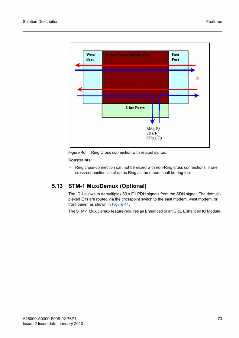
A25000-A0300-F008-02-76P1Issue: 2 Issue date: January 2010
73
Solution Description Features
Figure 40 Ring Cross connection with related syntax
Constraints:
– Ring cross-connection can not be mixed with non-Ring cross connections, if one cross-connection is set up as Ring all the others shall be ring too.
5.13 STM-1 Mux/Demux (Optional) The IDU allows to demultiplex 63 x E1 PDH signals from the SDH signal. The demulti-plexed E1s are routed via the crosspoint switch to the east modem, west modem, or front panel, as shown in Figure 41.
The STM-1 Mux/Demux feature requires an Enhanced or an GigE Enhanced IO Module.

74 A25000-A0300-F008-02-76P1Issue: 2 Issue date: January 2010
Solution DescriptionFeatures
Figure 41 STM-1 Mux/Demux Capability
g The optional 16xE1 expansion I/O unit is not supported in the STM-1 Mux/Demux configuration.
5.14 Loop-back
5.14.1 E1 LoopbacksThe IDU provides system loopbacks as a means for test and verification of a unit, link, and/or network. A variety of loopback points, are available. Loopback points and duration are easily selected through the Graphical User Interface.
The E1 loop-backs are available for the aggregate signal or for a single E1 stream.
5.14.1.1 Loopbacks for the aggregate signalThese loopbacks operate on the aggregate signal and cause the loopback of all the E1 streams.
Three aggregate loopbacks are available:
– Local LIU loop-back– Local Modem loop-back– Remote LIU loop-back

A25000-A0300-F008-02-76P1Issue: 2 Issue date: January 2010
75
Solution Description Features
Local LIU loop-backThe tributary signal can be looped back at LIU level. This type of loop-back when acti-vated allows testing the integrity of the line interface access circuitry.
Figure 42 Local LIU loop-back
Local Modem loop-backThe tributary signal can be looped back at MODEM level. This type of loop-back when activated allows testing the integrity of the line interface access circuitry.
Figure 43 Local Modem loop-back
Remote LIU loop-backEach E1 tributary stream can be looped back in the remote station, just before the E1 output interface. This type of loop-back, when activated, allows testing connection integ-rity between two terminals, with the only exception of the E1 physical output drivers of the remote terminal.
Figure 44 Remote LIU loop-back
5.14.1.2 Loopbacks for a single E1 streamThese loopbacks are performed on a single E1 stream.
Two loopbacks are available:
– Near End loopback: the transmission is sent back to the reception in the local NE.

76 A25000-A0300-F008-02-76P1Issue: 2 Issue date: January 2010
Solution DescriptionFeatures
– Far End loopback: the reception is sent back to the reception in the remote NE.
5.14.2 STM-1 loopbacksThere are different types of loopbacks according to the processing performed on the STM-1 signal. Two types of processing can be performed:
– STM-1 transparent– STM-1 with MUX/DEMUX option
5.14.2.1 Loopbacks with STM-1 transparentTwo loopbacks are available:
– Local loopback: the Tx side is loopped back to the Rx side in the local NE;– Remote loopback: the Rx side is loopped back to the Tx side in the remote NE.
5.14.2.2 Loopbacks with STM-1 with MUX/DEMUX optionTwo loopbacks are available:
– Facility loop: A signal received on the front-panel STM-1 port is looped back and transmitted out the STM-1 front-panel port;
– Terminal loop: A signal received from the RF link is looped back to the RF link.

A25000-A0300-F008-02-76P1Issue: 2 Issue date: January 2010
77
Solution Description Management
6 Management
6.1 IDU and Network management There are three ways of accessing all the IDU parameters:
1. Via HTTP using a standard web-browser to access the built in webserver.2. Via SNMP using the fully featured MIB, to automatize data collection and network
management.3. Via a client line command accessible from a terminal client connected to the serial
port.
The GUI (HTTP), SNMP, and CLI interfaces are detailed in the OMN Manual.
6.2 IP address Each IDU is independently configured for network parameters such as IP address, subnet, and gateway. However, the IDU also supports the functionof DHCP client, in which case the IP address can be assigned to the IDU through a DHCP server. A specific IP address may be associated with a particular IDU by configuring the DHCP server to serve IP addresses based upon the IDU Ethernet MAC address.
6.3 Network The IDU uses an "Out-of-Band" NMS network which is separated from the payload Ethernet network. Each IDU contains a managed Layer 2 Ethernet switch that supports Spanning-Tree Protocol (STP) for NMS traffic management. This allows the IDU to be configured in a protected ring configuration where the STP will prevent an Ethernet loop in the ring. This will also allow the ring to re-configure should an outage occur. The IDU acts as a network bridge via the Ethernet switch and the STP. The IDU does not cur-rently support NMS routing facility.
6.4 NMS Network Operational Principles The IDU does not provide routing facility. Therefore, all IDUs must be on the same subnet as the PC being used to access the IDU. If the IDUs and/or the PC are on dif-ferent subnets, a router must be used, with the gateway addresses suitably. Figure 45 shows the PC and both IDUs in the same subnet. In this case, no router is required. Figure 45 shows the PC and one of the IDUs in one subnet and the other IDUs in another. In this case, a router is required. Note how the GW addresses are set to allow interaction between the PC and the IDU in the other subnet.

78 A25000-A0300-F008-02-76P1Issue: 2 Issue date: January 2010
Solution DescriptionManagement
Figure 45 PC and IDU on same subnet
Figure 46 IDU on different subnets
6.5 Third Party Network Management Software Support The IDU supports SNMPv1, SNMPv2, and SNMPv3 protocols to be used with third party network management software. The SNMP agent will send SNMP slots to specific IP addresses when an alarm is set or cleared. Information contained in the slot includes:
– IP address– System uptime– System time– Alarm name– Alarm set/clear detail
The IDU may also be managed via HTTP, TELNET, and SSH protocols.
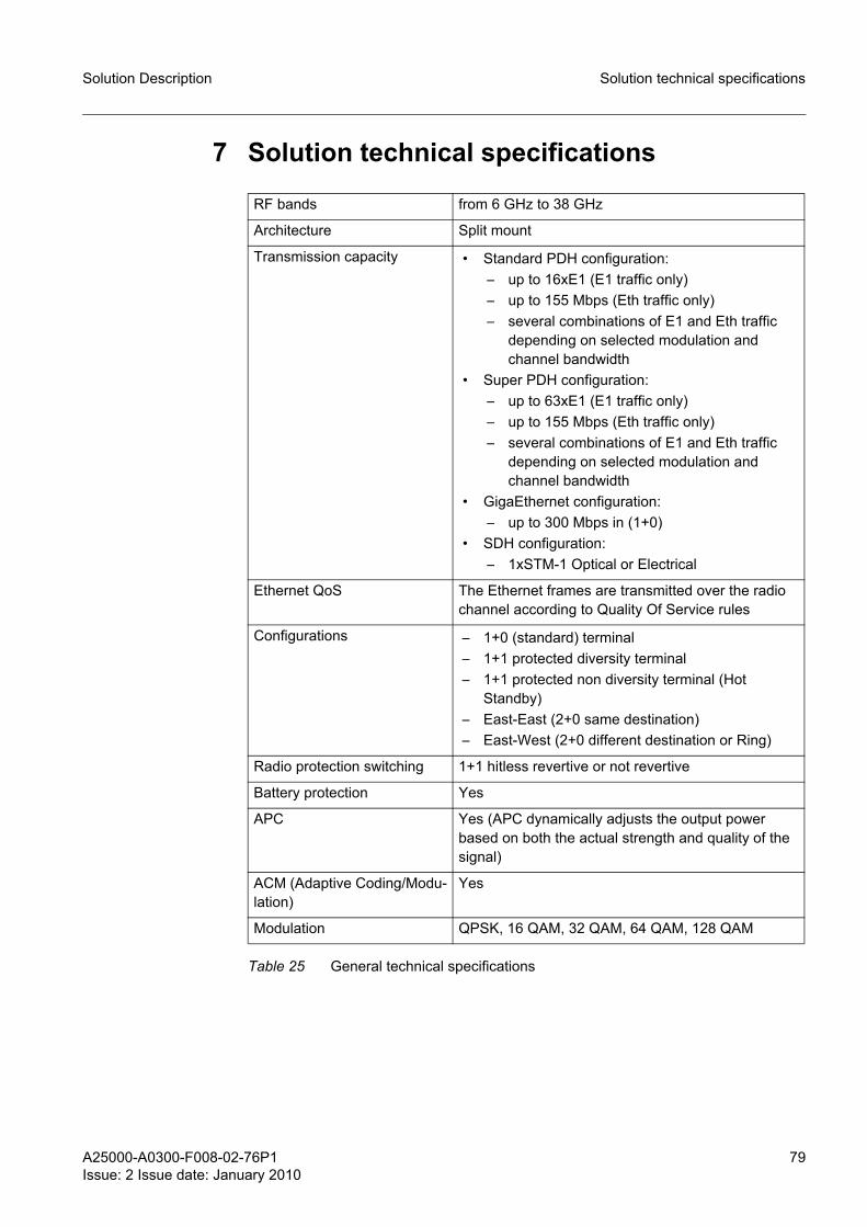
A25000-A0300-F008-02-76P1Issue: 2 Issue date: January 2010
79
Solution Description Solution technical specifications
7 Solution technical specifications
RF bands from 6 GHz to 38 GHz
Architecture Split mount
Transmission capacity • Standard PDH configuration:– up to 16xE1 (E1 traffic only)– up to 155 Mbps (Eth traffic only)– several combinations of E1 and Eth traffic
depending on selected modulation and channel bandwidth
• Super PDH configuration:– up to 63xE1 (E1 traffic only)– up to 155 Mbps (Eth traffic only)– several combinations of E1 and Eth traffic
depending on selected modulation and channel bandwidth
• GigaEthernet configuration:– up to 300 Mbps in (1+0)
• SDH configuration:– 1xSTM-1 Optical or Electrical
Ethernet QoS The Ethernet frames are transmitted over the radio channel according to Quality Of Service rules
Configurations – 1+0 (standard) terminal – 1+1 protected diversity terminal – 1+1 protected non diversity terminal (Hot
Standby)– East-East (2+0 same destination)– East-West (2+0 different destination or Ring)
Radio protection switching 1+1 hitless revertive or not revertive
Battery protection Yes
APC Yes (APC dynamically adjusts the output power based on both the actual strength and quality of the signal)
ACM (Adaptive Coding/Modu-lation)
Yes
Modulation QPSK, 16 QAM, 32 QAM, 64 QAM, 128 QAM
Table 25 General technical specifications

80 A25000-A0300-F008-02-76P1Issue: 2 Issue date: January 2010
Solution DescriptionSolution technical specifications
FEC type Modulation FEC
QPSK 7/8
16 QAM 7/8
32 QAM 9/10
64 QAM 11/12
128 QAM 13/14
IDU-ODU cable Max. IDU/ODU distance:
• HC AP/CC ODU – 100 m (with braided 50 ohm coax. cable)
• HC AP ODU – 80 m (with braided 50 ohm coax. cable)
For installations that require cable longer than 100 m a 1/2” cable can be used.
The max cable lenghts are as follows:
• ODU HC AP/CC: max 250 m • ODU HC AP: max 230 m
ODU 6L GHz 6U GHz 7 GHz 8 GHz 11 GHz 13 GHz
HC AP/CC 10±2 dB 10±2 dB 10±2 dB 10±2 dB 10±2 dB 10±2 dB
HC AP - - - - - -
Table 26 RTPC range (6-13 GHz)
ODU 15 GHz 18 GHz 23 GHz 26 GHz 32 GHz 36 GHz
HC AP/CC 10±2 dB 10±2 dB 10±2 dB 10±2 dB - -
HC AP - - - - 10±2 dB 10±2 dB
Table 27 RTPC range (15-38 GHz)
Table 25 General technical specifications (Cont.)
6L GHz 6U GHz 7 GHz 8 GHz 11 GHz 13 GHz 15 GHz 18 GHz 23 GHz 26 GHz 32 GHz 38 GHz
+24 dBm
+24 dBm
+23 dBm
+23 dBm
+22 dBm
+21 dBm
+20 dBm
+19 dBm
+18 dBm
+17 dBm
+14 dBm
+14 dBm
Table 28 Max output power (at ODU flange)

A25000-A0300-F008-02-76P1Issue: 2 Issue date: January 2010
81
Solution Description Solution technical specifications
Signal BW
Modulation ETSI Nominal Bit Rate
RF band [GHz]
L6 U6 7 8 11 13 15 18 23 26 32 38
7 MHz QPSK 8 Mbit/s - - - - - - -90.0 -90.5 -89.5 - - -
16QAM 2*8 Mbit/s - - - - - - -81.0 -81.5 -80.5 - - -
14 MHz QPSK 2*8 Mbit/s - - - - - -89 -88.5 -88 -86 -82 -83 -81
16QAM 34 Mbit/s - - - - - -83 -82.5 -82 -80 -80.5 -78 -79
32QAM STM0 (51) - - - - - -77 -77 -78 -75 -74 -74 -76
28 MHz QPSK 34 Mbit/s -84 - - - - -86 -85 -86 -83 -82 -83 -82
16QAM 2*34Mbit/s -78 - - - - -79 -80 -81 -78 -77 -76 -78
32QAM 2*STM0 -74 - - - - -76 -76 -77 -74 -72 -72 -74
64QAM 2*STM0 -72 - - - - -72.5 -72.5 -73 -72 -70 -68 -70
128QAM STM1 -66 -66 -68 -68 -68 -68 -68 -69 -67 -63.5 -64 -66
Table 29 BER = 10-6 Rx threshold (dBm)
Configu-ration
6L GHz
6U GHz
7 GHz 8 GHz 11 GHz
13 GHz
15 GHz
18 GHz
23 GHz
26 GHz
32 GHz
38 GHz
1+0 114 W 114 W 114 W 114 W 114 W 114 W 96 W 96 W 96 W 96 W 96 W 96 W
1+1 216 W 216 W 216 W 216 W 216 W 216 W 180 W 180 W 180 W 180 W 180 W 180 W
Table 30 Total power consumption (W)

82 A25000-A0300-F008-02-76P1Issue: 2 Issue date: January 2010
Solution DescriptionAcronyms and abbreviations
8 Acronyms and abbreviationsACM Adaptive Coding / Modulation
AGC Automatic Gain Control
AIS Alarm Indication Signal
ALS Automatic Laser Shutdown
AP Alternate Polarization
APC Automatic Power Control
ASIC Application Specific Integrate Circuit
ATPC Automatic Transmit Power Control
BBE Background Block Error
BER Bit Error Ratio
C/I Carrier-to-Interference ratio
C/N Carrier-to-Noise ratio
CCI Co-Channel Interference
CLI Command Line Interface
CRC Cyclic Redundancy Check
DDF Digital Distribution Frame
DHCP Dynamic Host Configuration Protocol
DTI Double Tributary Interface
DSL Digital Signal Line
E2PROM see EEPROM
EEPROM Electrically Erasable PROM
EMS Element Manager System
EOW Engineering Order Wire
ETH Ethernet
ETSI European Telecommunication Standards Institute
FEC Forward Error Correction
FPGA Field Programmable Gate Array
GETH Giga Ethernet
HDB3 High Density Bipolar of order 3 code
HDLC High-level Data Link Control

A25000-A0300-F008-02-76P1Issue: 2 Issue date: January 2010
83
Solution Description Acronyms and abbreviations
HSBY Hot Stand-By
i/f Interface
IDU Indoor Unit
IF Intermediate Frequency
ITU International Telecommunications Union
LAN Local Area Network
LCT Local Craft Terminal
LED Light Emitting Diode
LLC Logical Link Control
LO Local Oscillator
LOF Loss of Frame
LOM Loss of Multiframe
LOP Loss of Pointer
LOS (1) Line Of Sight
(2) Loss Of Signal
LP Lower Order Path
LSB Least Significant Bit
MAC Medium Access Control
MAN Metropolitan Area Network
MIB Management Information Base
MS Multiplex Section
MSB Most Significant Bit
MTBF Mean Time Between Failures
MTU Maximum Transmission Unit
NE Network Element
NF Noise Figure
ODU Outdoor Unit
PCB Printed Circuit Board
PDB Power Distribution Board
PDH Plesiochronous Digital Hierarchy
PDU Protocol Data Unit
PLM Path Label Mismatch

84 A25000-A0300-F008-02-76P1Issue: 2 Issue date: January 2010
Solution DescriptionAcronyms and abbreviations
PM (1) Performance Monitoring
(2) Poll-Me Bit (IEEE only, not to be used)
PMP Point-to-Multipoint
ppm Part per Million
PPP Point-to-Point Protocol
PRBS Pseudo-Random Binary Sequence
PS (1) Power Supply
(2) This is also used for Physical Slot (IEEE only, not to be used)
PSK Phase Shift Keying
PtP Point to Point
QAM Quadrature Amplitude Modulation
QoS Quality Of Service
QPSK Quadrature Phase-Shift Keying
RAM Random Access Memory
RDI Remote Defect Indication
REI Remote Error Indication
RF Radio Frequency
RIP Routing Information Protocol
RLTS Received Level Threshold Seconds
ROM Read Only Memory
RPS Radio Protection Switching
RS (1) Reed-Solomon (Coding algorithm)
(2) Regenerator Section (SDH)
RSP Response
RSPI Radio Synchronous Physical Interface
RSS Received Signal Strength
RSSI Received Signal Strength Indicator
Rx Receiver / Reception
SDH Synchronous Digital Hierarchy
SDIDU Software defined IDU
SEEP Serial E2PROM
SES Severely Errored Second

A25000-A0300-F008-02-76P1Issue: 2 Issue date: January 2010
85
Solution Description Acronyms and abbreviations
SNMP Simple Network Management Protocol
SVR Software Version Release
TCM Trellis Code Modulation
TIM Trace Identifier Mismatch
TNMP Trivial Network Management Protocol
ToS Type of Service
TV Televalue (Proprietary TNMP property)
Tx Transmitter / Transmission
USB Universal Serial Bus
VC-n Virtual Container - n
VLAN Virtual Local Area Network
VP Virtual Path
WFQ Weighted Fair Queueing
XML Extensible Markup Language
XPIC Cross Polar Interference Canceller