SolPEX: Bragg-crystal rotating spectro-polarimeter for · PDF fileBragg-crystal rotating...
36
SolPEX: Bragg-crystal rotating spectro- polarimeter for the Russian Kortes module of the ISS Janusz Sylwester Solar Physics Division of SRC-PAS Wrocław SolPEX: Solar Polarimetry Experiment
Transcript of SolPEX: Bragg-crystal rotating spectro-polarimeter for · PDF fileBragg-crystal rotating...
SolPEX: Bragg-crystal rotating spectro-
polarimeter for the Russian Kortes module of the ISS
Janusz Sylwester Solar Physics Division of SRC-PAS
Wrocław
SolPEX: Solar Polarimetry Experiment

Motivation
• Reliable detection of X-ray polarisation provides unique, yet unexplored tool of studying non-isotropic distribution of particles in the solar corona
• Ubiquitous presence of collimated non-thermal electron beams during flare impulsive phase is indispensable in order to explain observed patterns of hard X-ray flare emission
Present opportunity • Russian Academy of Sciences P.N. Lebedev Institute (FIAN)
recently became involved in design of the Kortes Package of instruments to be put on the solar pointed platform attached to the Russian Module aboard the ISS. Expected launch 2015-2016
• FIAN (Professor Sergey Kuzin: Head)offered SRC-PAS Solar Laboratory in Wrocław a possibility to place an instrument for testing new measurement concepts.
• Our Team decided to take this opportunity and designed the SolPEX instrument intended for measurements of solar soft X-ray spectra, simple imaging and line polarisation detection through Bragg crystal spectroscopy
• Official Collaboration bi-lateral protocols have been signed between SRC-PAS and FIAN on 15th November 2012 and are to be approved by the PAS-RAS top-level working group in two weeks’ time
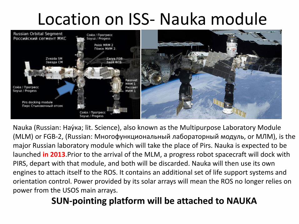
Location on ISS- Nauka module
Nauka (Russian: Нау́ка; lit. Science), also known as the Multipurpose Laboratory Module (MLM) or FGB-2, (Russian: Многофункциональный лабораторный модуль, or МЛМ), is the major Russian laboratory module which will take the place of Pirs. Nauka is expected to be launched in 2013.Prior to the arrival of the MLM, a progress robot spacecraft will dock with PIRS, depart with that module, and both will be discarded. Nauka will then use its own engines to attach itself to the ROS. It contains an additional set of life support systems and orientation control. Power provided by its solar arrays will mean the ROS no longer relies on power from the USOS main arrays.
SUN-pointing platform will be attached to NAUKA

Pro and contras of using ISS as an observing platform
• Easy access to ISS, instrument mounting by cosmonauts
• Possibility of using large instruments
• No substantial limitation on power
• Large volumes of data storage on „popular” media
• Possibility of „repairs” and memory module transport to the ground
• Rough Pointing- few arcmin due to ISS motions
• Spacecraft day/night shifts (16 nights/24h)
• Vignetting by various ISS structures only ~10 min of uninterrupted measurements per orbit possible
ISS suitable for tests of new experimental ideas

Kortes- FIAN Module- goals S. Kuzin
• Scientific goals – Monitoring of solar activity with high spatial resolution – Investigation of pre- and flaring energy release processes
• Scientific goals – Monitoring of solar activity by means of EUV telescopes
for the 304 and 171 A (? +other channel) – Spectroscopic observations for flaring plasma diagnostic,
including creation of spectral lines catalog for solar flares – Investigation of eruptive events, including the investigation
of their trajectories in the near-corona – Investigation of parameters of Earth atmosphere by EUV
absorption techniques

Block placement S. Kuzin
• Block of detectors – vacuum space outside the ISS on 2D-platform
• Block of electronics – inside the ISS
• Block of FIAN detectors: – 5 channels (right now, changes are possible) – 2 telescopes – 171 and 304 Å (some other channel
for technology & science testing) – 2 spectroheliographs 180-210 Å & 280-330 Å
(? 220-270 Å ) – X-ray spectropolarimeter SolPEX (0.5-15 keV)

• Ethernet IEEE 802.3 protocol to be used for data transfer to ISS
• ~few GB/24h average transfer rate to the ground
• If necessary, a large data bump memory storage possible
• Transfer of data on SSM possible up to many hundreds of GB
• Quick-look data transfer at the rate of 1 MB/24h
Data storage & transfer

Overall characteristics
Kortes
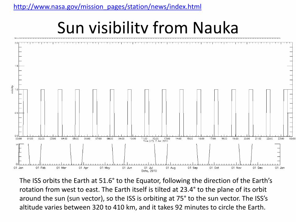
Sun visibility from Nauka
The ISS orbits the Earth at 51.6° to the Equator, following the direction of the Earth’s rotation from west to east. The Earth itself is tilted at 23.4° to the plane of its orbit around the sun (sun vector), so the ISS is orbiting at 75° to the sun vector. The ISS’s altitude varies between 320 to 410 km, and it takes 92 minutes to circle the Earth.
http://www.nasa.gov/mission_pages/station/news/index.html
10 min

SolPEX objectives
• Detect measurements of polarisation in soft_X-ray continuum emission and possibly in selected emission lines (1-2 % detection limit) (B-POL)
• Measurements of X-ray spectra evolution with very high time resolution (0.1 s) rotating drum spectrometer (RDS)- idea proposed by Stefan Plocieniak
• Imaging the soft X-ray Sun with moderate spatial (~20arcsec) and high time resolution (0.1 s) pin-hole imager (PHI)
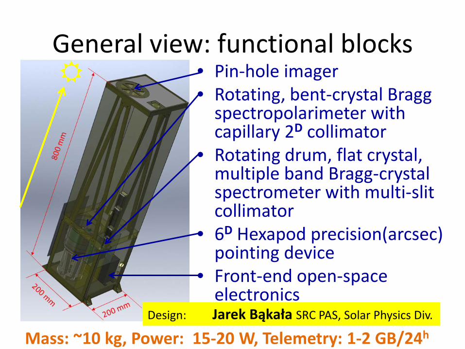
General view: functional blocks • Pin-hole imager • Rotating, bent-crystal Bragg
spectropolarimeter with capillary 2D collimator
• Rotating drum, flat crystal, multiple band Bragg-crystal spectrometer with multi-slit collimator
• 6D Hexapod precision(arcsec) pointing device
• Front-end open-space electronics
Mass: ~10 kg, Power: 15-20 W, Telemetry: 1-2 GB/24h
Design: Jarek Bąkała SRC PAS, Solar Physics Div.

Locate the X-ray source on the Sun
Pin-hole imager (PHI) E range: 1-10 keV, dE: ~1 KeV
• Primary role: localize sources (AR & flares) on the disk in the instrument coordinate system
• Secondary: detect active phenomena on the disk, analyse individual lightcurves for separate AR
• Easy concept: pin-hole (adjusted diameter open down to 0.1 mm, can be changed depending on the activity), CCD detector (256 x 1024 pixels 26 µ)
• Image readout: each 0.2 s • Will provide positions [x,y] of more prominent
individual sources (resolution 1.5 arcmin). • Limited spectroscopy, similar to RHESSI at
lower energy range (Fe XXV and Fe/Ni line groups distinguishable)

Detectors Amptek SDD
4 units
detector SDD: 25 mm2/500 µm Si Be window: 12.7 or 8µm E> 1 keV

6D Hexapod new precise pointing system
http://www.physikinstrumente.com/en/products/prdetail.php?sortnr=700884
Mass: 2.2 kg
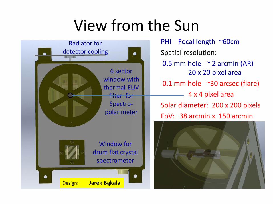
View from the Sun PHI Focal length ~60cm Spatial resolution: 0.5 mm hole ~ 2 arcmin (AR) 20 x 20 pixel area 0.1 mm hole ~30 arcsec (flare) 4 x 4 pixel area Solar diameter: 200 x 200 pixels FoV: 38 arcmin x 150 arcmin
Design: Jarek Bąkała
Radiator for detector cooling
6 sector window with thermal-EUV
filter for Spectro-
polarimeter
Window for drum flat crystal
spectrometer

Rotating Polarimeter unit & PHI detector
• Si 111 bent crystal at Brewster angle ~45° • Pin-hole image of the
~ 6 mm • CCD detector (1024x256
pixels) • Rotating at 1 rev./s along
the axis ǁ to • Linear polarization plane
______________

Removing heat from the rotating section
• Rotating section connected to the emitting drum
• Still-heat receiving drum connected to external radiator
• Heat transfer through radiation between the two

Reflection of linearly polarised X-rays
http://cheiron2007.spring8.or.jp/pdf/2_02B1.pdf
σ
π Brewster’s Angle: the reflectivity equation for π-component gives minimum when the numerator becomes zero. This angle is known as Brewster’s angle.

Spectro-Polarimeter monocrystal wafer: cylindrical Si 111 courtesy Zaneta Szoforz
2d=6.271 Å Spectral range:
3.940 - 4.505 Å Radius of curvature:
180.0 mm Crystal length & width:
38.2 & 10 mm Calculated ideal FWHM & Resolution:
4.4 arcsec ~ 0.0005 Å < line thermal wdths
CCD

Polarisation detection pattern for carefully selected spectral range
• For 100% linearly polarised incoming X-ray
illumination
The amplitude of
rotational modulation
At 4.44 Å

Why this selection?
• Continuum and line emission should be prominent for a wide range of physical conditions on the Sun i.e. AR and/or flares
• Clean spectral range in the vicinity of the line, allowing for separate measurements for the continuum and line rotationally modulated pattern

SXV w3 line and the selected band • The line is the third
strongest on the 1-6 Å band spectrum.
• The neighbouring continuum is free from other lines
• S XIV d3 (satellite-to-parent) line complex is measurable allowing for estimates of T
• Spectral band selected contains lines of Ar & Cl making thus possible study of respective absolute abundances
• The SXV w3 line has been observed by RESIK only occasionally at the edge of spectral bands 2 and 3 depending on the source locaton on the disk

The need for bright & isolated source Selecting isolated AR or flare is crucial to avoid overlapping the spectra
• Should NOT be a full disk instrument *many sources usually exist – Spectral
overlapping – Various
polarisation planes
The Capillary collimator ~2 arcmin
http://www.collimatedholes.com/about.html
Glass Capillary Arrays (GCAs) consist of millions of precision glass capillary tubes fused together to produce a uniform and mechanically rigid structure. They can be supplied as circular or rectangular thin plates and offer sieve-like filtration with a positive particle size cut-off. GCAs are strong, self-supporting devices with exceptional thermal and chemical stability; they can be manufactured to withstand temperatures greater than 450 °C for applications in severe environments.

Spectra to be recorded from an isolated source
Bremsstrahlung continuum Can be polarised
Line emission- may be Differently polarised…
Third order emission should not be a problem Orders of magnitude weaker Second order emission is forbidden NOT a problem !!!
Cl tr
iple
t
What will be measured
• Roational modulation (1s revolution) signal on CCD- 6 fringes at 60 deg separation.
• CCD spectrum will be recorded & dumped every 0.02 s or better. Can be synchronized with open window crossings. 7 deg accuracy of readout
• Dark current measurements will be possible when the crystal is behind occulting fringes
• CCD „dump” (spectrum) will provide charges & timing down to few msec.

Where & when the polarisation is expected
• The electrons during their acceleration obtain a preferred direction and only afterwards their velocity distribution becomes a Maxwellian by means of collisions
• The time needed in this cooling phase for the transition to thermal conditions may be estimated at between tens of seconds to some minutes depending on surrounding density and electron energy
• It is reasonable to suppose that the electrons producing non-thermal radiation have a non-isotropic velocity distribution. This is in agreement with multiple spectral and imaging observations in harder X-rays

Early theory predictions

Some recent polarisation measurements McConnell et al. (2003) have reported preliminary observations of hard X-ray linear polarization in a large (GOES class X4.8) solar flare observed with the Ramaty High Energy Solar Spectroscopic Imager (RHESSI) satellite on 2002 July 23. This marks the first report of linear hard X-ray polarization in an event for which detailed temporal, spectral and spatial information on the hard X-ray emission was available. The 2002 July 23 event exhibited many of the characteristics of nonthermal electron propagation, such as a hard power-law spectrum at high energies (Holman et al. 2003) and the appearance of bright footpoints (Emslie et al. 2003). The magnitude of the hard X-ray polarization reported by McConnell et al. (2003),∼15%, is indeed compatible with most of the models that involve the downward precipitation of a beam of nonthermal electrons. However, contrary to the predictions of such models, the direction of the reported polarization vector is not aligned with the local radial direction on the solar disk; rather, it is rotated counterclockwise by some tens of degrees relative to the local solar radial, in a direction roughly corresponding to the orientation of the line joining the bright X-ray footpoint sources (see Fig. 1 of Krucker et al. 2003).

New perspectives
• Possibility of detection the modulation pattern for continuum and line emission on 1s timescales
• Determination of polarisation plane(s)- comparison with concurrent Kortes imaging

New concept: a very high time resolution (0.1s) spectroscopy for flares Stefan Płocieniak
• Fast rotating drum equipped with 3 pairs of identical crystals in the Dopplerometer orientation Bragg-illuminate the ”standard” SDD detectors’
• Thanks to the rotation photons are being „reflected” from the crystal.
• By monitoring the photon arrival time, accurate „intercept” angle can be estimated & converted to wavelength
• Histogram spectrum will be revealed with sufficient amount of detections

Rotating Drum Flat spectrometer unit concept of Stefan Plocieniak, SRC PAS
• Single emitting solar AR selected by the multi-slit collimator, based on PHI data
• Fast rotating (10rev/s) drum with a set of 6 crystals (3 pairs of identical flat monocrystals Dopplerometer configuration)
• 4 large area ~0.25cm2 PIN detectors

Spectra reconstruction from a fast rotating crystal drum
• Angular position of the detector event (1 μsec accuracy) ~few arcsec angle determination accuracy less than line FWHM

Modelling the effective area
• At any detection time instant, an effective area can be assigned & respective probability of detection accounted for
Bragg angle

Summary
• Kortes opportunity is unique for testing new measurement ideas
• Very short design time is an obstacle, but many components are already at hand & tested at SRC PAS SPD
• Detailed ground calibration & alignment & testing (innovative) procedures are necessary
• New measurement techniques can be tested and interesting flare physics can possibly be revealed

Bibliography
• MARK L. MCCONNELL, RHESSI AS A HARD X-RAY POLARIMETER, Solar Physics 210: 125–142, 2002.
• Sa¨m Krucker, HARD X-RAY SOURCE MOTIONS IN THE 2002 JULY 23 GAMMA-RAY FLARE, ApJ 595:L103–L106, 2003
• Gordon Emslie, Hard X-Ray Polarization from Non-vertical Solar Flare Loops, 674 (2008) 570
• Elvert, On the polarisation and anisotropy of solar X-ray radiation during flares, Sol. Phys. 15, 234-248, 1970