Solo Manual on - PlanetPPG Powered Paraglidingplanetppg.com/content/pdf/solo_manual.pdf · table of...
29
SOLO MANUAL ASSEMBLY OPERATION MAINTENANCE
Transcript of Solo Manual on - PlanetPPG Powered Paraglidingplanetppg.com/content/pdf/solo_manual.pdf · table of...

SOLO MANUAL
ASSEMBLY OPERATION MAINTENANCE

TABLE OF CONTENTS
02
SOLO MANUAL
ASSEMBLY THE MOTOR 03
TECHNICAL DATES 06
FUEL AND OIL 07
CARBURETTOR AND INTAKESILENCER 08
ENGINE 11
PULLSTARTER 14
GEARBOX 15
PROPELLER 17
ELECTRIC 19
POWER IGNITION SYSTEM 20
E-STARTER 21
EXHAUST 22
THROTTLE RESPECT 23
THROTTLE AIRBOSS 24
HARNESS 25
CHECKLIST 28

ASSEMBLE THE MOTOR
03
SOLO MANUAL
Open the pagage with care. Do not use long knife. Parts inside the carton could be damaged.
Check the parts and proof for completeness.
Bring the four cageparts together and fi x with velcostraps.
Put the motor in front of the completed cage.

ASSEMBLE THE MOTOR
04
SOLO MANUAL
Take the motor and press the cage against the black clipse. Inside the black clips is a bolt which belong in the hole of the cage.
The cage should fi xed against the frame with the velcro.
After assembling all velcro´s should tighten again.

ASSEMBLE THE MOTOR
05
SOLO MANUAL
In case that you have a shellform-backstuffi ng fi x it on the left and rigth side.
Most maintainance you can make by yourself with the original tools.
Contents:Hexagon 4/5/6 mmWrench 8/10/24Wrench for sparking-plug and screw driverBeltdressing
The Shellform-backstuffi ng prevent that the motor will turn to cause from torc.
The backstuffi ng will fi xed also with velcro. The upper and lower ends from backstuffi ng turn arround the upper and lower rope.

06
SOLO MANUAL
TECHN I CAL DATES
Motor Solo 210ccm
Type 2 Stroke,1 Cylinder
Power 12 kW
Cooling Air
Starter Manuel / E-Starter
Carburettor Bing 84,32mm
Exhaust Resonator
Propeller 2-Blade
Diameter 38“-48“ (96-122 cm)
Weight 50 lb (23 kg)
Tank capacity 10 liter
Max. take off weight 308 lb (140 Kg)
Consumtion arround 3 l/h
Max. airborne time up to 3 h
RPM 0-5800 1 /min
Staticthrust up to 132 lb (60 kg)
Climbrate up to 2 m/sec.
Little throttle less consumtion
Big throttle high consumtion
Low fl ightlevel less consumtion
High fl ightlevel high consumtion
Small glider high consumtion high speed
Big glider less consumtion slow speed
Leightweight pilot less consumtion slow speed
Heavyweight pilot high consumtion high speed
NEXT DATES ARE DEPEND FROM:WEATHER, ALTITUDE, PILOTS WEIGHT, GLIDER AND SIZE AS WELL AS ATMOSPHERIC HUMITY.
RESULT FROM THROTTLELEVER-POSITION, FLIGHT-LEVEL, GLIDER AND SIZE AND PILOTSWEIGHT FOR THE CONSUMTION.

FUE L AND O I L
07
SOLO MANUAL
The motor will delivered with two lid´s. The fi rst is for fl ight with a small hole. The second lid is closed for transport. If you try to fl y with the closed one the motor will have a ”in fl ight shut down” after a while. It´s will establish inside the tank a vacuum. The carburettor get fuel from tank through gravity.
The fuel comes from tank through this fi lter. Check before fl ight.
IMPORTANT INFORMATION
The fuel should have 98 octane or 100 LL. The best oil is Castrol RS 2T. Mix 2 % in addition to the fuel.
For the fi rst 10 h mix 4 % in addition to the fuel. In this time use full throttle very careful.
This picture demonstrate a closed petroltap.

08
SOLO MANUAL
The Intakesilencer is fi xed on two positions. One with a clamp on the carb and one with a rubberline on the top.
In some fl yingareas it´s necessary to use such a airfi lter. Use only original parts. Otherwise you risk to loose power.
How I change the needle? Open the lid with the two screws and pull out all parts which are hanging on the cable.
CARBURETTOR AND INTAKESILENCER

09
SOLO MANUAL
Press the spring togehter and loose the cable from slider. Now you hold slider and lid apart in your hand. The needle is now loose inside the slider. At our factory we installed the 6L1 in the top position.
Here you see succsession from:Lid/spring/giude piece/needle with ring/slider
Why I should change the main jet? Each motor will checked and testet before he leave our factory. During this time we fi nd the suitable jet. Nevertheless the motor is running bad at your fi rst trial. At full throttle the motor runs rough (rpm less than 5600 1/min).
The reason is: Other metrologic conditions, higher altitude, more hu-mity, higher temperatur. Normally the main jet is 155. Replace this into a smaller one (150). You fi nd this inside the toolbox.
CARBURETTOR AND INTAKESILENCER
How to change the mainjet? Press the bow back. With the 8 mm wrench screw out the jet.
Attention: Do not loose the small red fi lter.

10
SOLO MANUAL
Overfl oating Carburettor. Fuel comes out of the two small tubes. The two swimmer regulate the niveau inside the carb. To reduce the quan-tity in the carb bend the little tongue careful.
If you hold the carb up side down,the swimmerforc is not parallel to the carburettorcase. If the carb overfl oat while using the motor the forc should look a little bit more upward.
Before you start the cold motor press down the choke. Start the motor and after a few seconds release the choke.
CARBURETTOR AND INTAKESILENCER
The big screw regulate the idlerunning. Turning right-high rpm. Turning left lower rpm.The idlespeed should round about 2600 1/min.The smaller screw is responsible for fuelmixture in idle.Turning right-rich.Turning left-lean

ENG INE
11
SOLO MANUAL
This picture demonstrate the nacked motor.
In fl ight the motor will become very hot. The most stressed airea are the piston and the rings.Remove the exhaust and have a look to appe-arenced piston with it´s rings. Test it with screwdriver.The rings should be loose inside the slot.
How to replace the piston?At fi rst remove the four nuts from the feed of the cylinder.
Now draw off the cylinder from piston.
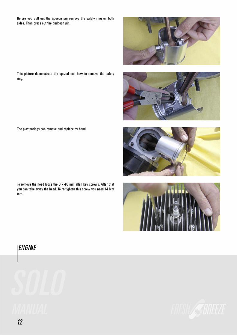
Before you pull out the gugeon pin remove the safety ring on both sides. Than press out the gudgeon pin.
This picture demonstrate the spezial tool how to remove the safety ring.
The piostonrings can remove and replace by hand.
ENG INE
12
To remove the head loose the 6 x 40 mm allen key screws. After that you can take away the head. To re-tighten this screw you need 14 Nm torc.
SOLO MANUAL
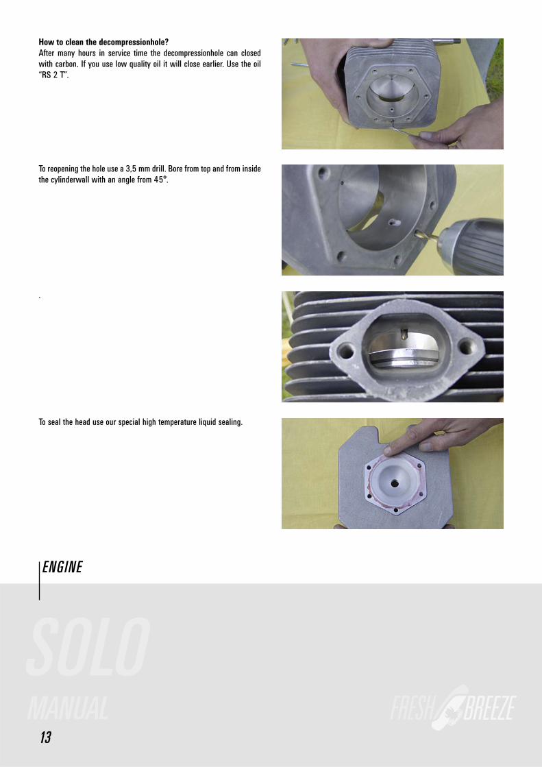
How to clean the decompressionhole?After many hours in service time the decompressionhole can closed with carbon. If you use low quality oil it will close earlier. Use the oil “RS 2 T”.
To reopening the hole use a 3,5 mm drill. Bore from top and from inside the cylinderwall with an angle from 45°.
.
ENG INE
13
To seal the head use our special high temperature liquid sealing.
SOLO MANUAL

PULLSTARTER
14
SOLO MANUAL
Replacment of the starterrope:Unsrew the starter-lid, take off the façade plus fi nger. The white disc should now be removed by pressing it against the tension-force.
The white disc can now be taken out of the lid.
The starter-rope can be pulled out of the disc.
To give the starter-rope advanced tension one,place the rolled up into the slot and rotate three times.

GEARBOX
15
SOLO MANUAL
The power-transmission of the gears happens via a Poly V Belt (725 or 730 8 PK). The transmission ratio equals 1:2,57. The number of the re-volution at full load equals 2350 rpm. The lifespan of the belt is aprox. 50-100 hrs. Too little tension shorthens the belt lifspan drastically.
During maintenance check the belt before each fl ight. The belt should not be able to be turn over 45° degrees. After the fi rst fl ight it is es-sential to pay special attention to the belt.
How to tighten the belt?1. Loosen the central screw (24 mm)
2. Lift the rotor-hub with the tension-screw (5mm) in order for the belt to either tighten or subside, thus the belt can be loosend. Turn right- belt tighten. Turn left-belt loosens.3. Tighten central screw (36 NM) again.

16
SOLO MANUAL
How to replace the belt?1. Loosen the central-screw2. Loosen the belt with tension-screw.3. Screw in the piston-block into the spark-plug-hole
5. Unscrew starter-pinion
6. Take off belt.7. Place the new belt onto the pulley.
The re-fi tting happens in the revrese order.
GEARBOX
If the belt makes squeaking noises in spite of the proper tension, then spray twice onto the lower pulley. If the belt is slipping in spite of proper tension, then it needs to be replaced.

17
SOLO MANUAL
The propeller consist of the two parts which, put together, measure up to 122 cm in lengh. The weight is ca 900 gram. The propeller is made of gfk or cfk, which allow for small repairs. But it is essential that after repair is accomplish, the propeller gets balanced out again.
The propeller is fi xed onto the hub with 6 screws. Tighten the propeller, use 12 Nm torc.
How to balanced out the propeller?The propeller has to be placed vertically onto the balancing-out equip-ment. If turns to one side, then drill a 3,5 mm hole into the lighter half of the propeller.
PROPELLER
Then fi ll only as much resign into this hole until the propeller does not want to turn to one side only.

PROPELLER
18
SOLO MANUAL
Likewise proceed as above in the horizontal position.
Attention: An imballanced propeller created unnessecary vibration in the engine and can destroy many of it´s components.
Required materials for repairs and balancing-out!The propeller balancing-out-resing with hardener,syringe and a stored shaft for a free turning of the propellerblades
What do I require for repairing the propeller.Fiberglas-spatula and abrasive paper.
Here now an example when a propellerblade must not be repaired again. If the damage is to large, then repair are dangerous. The repairs sopt has not enough grip and may fall off whern the propeller turns at high revolution. Danger of accident is thus programmed.

E LECTR I C
19
SOLO MANUAL
ACCU
CONTROLERRELAIS
E-MOTOR
HIGH TENSION COIL
SPARK PLUG
KILL SWITCH
STARTSWITCH
12V PLUG
MAIN SWITCH
ALTINATOR COIL
FIRST COIL
GROUND
30
86
85
87

20
SOLO MANUAL
The engine is equiped with a powerful and service free ignition system. It consist of the components: stator, loading-coil of the ignition, genera-tor coil for the supply of electricity and rotor. To be able to work on the coils, the following should be taken care off.
Remove the complete ignitionbox including the lid of the starter. Now the rotor with the starter-pot is visible which is held into place by it´s central screw.
Once the central screw has been removed, the rotor can then be pulled off via a puller. Because the rotor has to be in a specifi c position to the crankshaft, the rotor with a suspension-disc on the crankshaft is preordained.
POWER I GN ITI ON SYSTEM
To fi ne-tune the ignition timingpoint one has to loosen the two secu-rity screws of the stator. Turn the stator to the left maximally to the furthest point, now turn ca 2 mm to the right again. Retighten the security screws. The ignition timingpoint has now its correct adjus-tment. When reassembling take special care of the correct distance of the contact-test that the distance of 0,25 mm is observed and if nessecary readjust.

21
SOLO MANUAL
If the engine is equipped with an e-starter, the power can be turned on just by pressing the botton on the throttle. The accu is fi xed on the side of the frame and sits in a holster. The accu-pack consist 14 x 1,2 Volt Nicad cells with max 1700 mAh.
Beside the Accuholster there is a switch with 0 and 1. Set on 0 the engine can´t be left running on the e-starter. Set on 1 the e-starter is functioning and ready to go. The Accu will only charged while running and with the switch on at the position 1. Look to the backside of the aluplate you see the controler with the coolingrips.
E-STARTER
Via this plug a voltage can be transmitted. The dynamo has a limit of max. 24 VA.
The cogwheelplay of the e-starter should be checked after dismante-ling the e-motor and need returning if nessecary. In order to accomplish this the M4 screws and the security clamp needs to be loosened. The e-motor can now be adjusted. The individual theeth of the cog should engage properly. To little cogwheelplay prohibits the light/smooth run-ning of the cogs at the start, Is the cogwheel too large, then the theeth of the pinion will die to early. The cogwheelplay could change again after tightening, then a re-check is essential.

22
SOLO MANUAL
The engine is equipped with a resonance exhaust which allows for an increase of performance and a decrease of excess noise. The white wrap around tape is made of fi berglass and gummen up with silicon.
The complete exhaust is suspended fl exibly as to prevent vibrational eruptions.
To keep the exhaust fl exibly mobile we chose different types of fi xtures. One is a rubber connection on the gear-plate and two a stress-bearing spring-gasket at the entry and the exit.
EXHAUST
After 10 hrs the sealing-rings and their fasten screws needs to be checked. The screw you have to changes each 25 hrs.

23
SOLO MANUAL
The throttle is taken according to the building kind into the right or left hand. The strap has a variable seize change. Before start the strap should be attracted fi rmly.
The Respect-thorttle-lever has in each case a switch at the tube. The one is for the starting the engine.
The other one for killing the engine.
THROTTLE R ESPECT
The thottle has also a travelling locking. After reaching the desired hight of fl ight, the throttle can be fi xed via the clasp-lever. Since long holt of the throttle is hard in hand, the throttle can be placed in position onto the legs. The hand are now free for other things.

THROTTLE AI RBOSS
24
SOLO MANUAL
The Airboss throttle-lever has also a button for killing the engine and where approbiate about one for starting the engine, if an electric star-ter is available.
First the throttle is taken into the hand...
...after that the steering line and at last the A-riser are grasped.
This picture clarifi es the handling of the riser and the throttle during the start.

HARNESS
25
SOLO MANUAL
This harness is specially constructed for motoring enterprises. Throug-hout the usage of the maschine, ensure that no lose ends are able to get into the propellerblades. The suspension for pilot can be perma-nently in the snap links.
The harness is secured via 3 springlocks; tow legs spring and one breast spring lock. It has two adjsutments possibilities. One there are the buckles which are fastenen onto the front of the seat. At the start these should be pulled on lightly, as to make the climbing into the harness easier at the lift-off. Before landing it is advisable to lower the seat fully, to enable a maximal favourable touch-down position. The leg loop does not need to be pulled too tightly.
The harness has also two pockets, which are easily reached at fl ight.
All other adjustment options are regulated while fl ying. Are the straps pulled rigth and left, then one sits up straight, are they loose a slight back prone position can be adopted.

HARNESS
26
SOLO MANUAL
Now one kneels in front of the engines and pulls the carrying straps over the shoulders.
Thereafter the pilotsuspension has to be hang into the dropping device of the engine. Usally the hind most hole is used for this. The dropping device should be activated at pending danger, for example at a water landing, fi re at high altitude or a tree touchdown. The activation occurs when the two strings of the dropping device are pulled outwards. Be-cause the engine is now not hanging over the suspension of the chute anymore, the pilot will be in a brought into a strong reclining position. Thus the engine can now slide easily over the shoulders. The landing proceeds from now on without the engine.

HARNESS
27
SOLO MANUAL
Now one get up with the whole engine and goes to the glider. The gli-der will then be hang into the springlocks for the pilots suspension.
After all has been done, the throttle and the break-loop had to be taken into the hand. The engine will now be started and the starting run can begin.
RESCUE SUSPENSION
The picture shows an example of how to fasten the recuedevice using the V-line. The rescuedevice should be connect with the pilot suspen-sion using the V-line. So it´s an optimal landing position in case of a possible release. The rescuedevice should not be hung in the harness using the spring hooks,because of supine in rescue release.

28
SOLO MANUAL
CHECKLI ST
CHECK BEFORE EACH FLIGHT
CAGE SECURED ON THE FRAME
CAGE IN GOOD SHAPE
PROPELLER-CLEARANCE
PROPELLER WITHOUT FREE SPACE
PROPELLER WITHOUT DAMAGE
BELT AND TENSION ENOUGH
KILLSWITCH O.K.
FUEL MIN.98 OCTANE OR HIGHER
FUEL TANK LEAKY
PILOT SUSPENSION AND STRAP WITHOUT STRESSMARKS
SPARKING PLUG AND WIRE WELL FIXED
TANK-LID WITH SMALL HOLE ON THE TANK
PROOF GLIDER,LINES AND RISER FOR STRESSMARKS OR DAMAGE´S.
INTAKESILENCER AND IT´S FIRMNESS
FULL RPM MIN 5600 1/MIN
CHECK ALL 10 HOURS
FUEL FILTER
CLEAN THE CARBCHAMBER
BELT
EXHAUST INCL. THE SELAINGRINGS AND THE SCREWS.
ALL CONNECTION FROM THE WIRES
CHECK ALL 50 HOUS
REPLACE THE BELT
METAL-WIRE FROM THROTTLE
REPLACE THE SPARKING PLUG AND THE CONNECTOR
REPLACE ALL RUBBERJOINT FROM EXHAUSTSYSTEM
REPLACE THE SEALINGRINGS AND THE SCREWS
CHECK ALL SCREWS

29
SOLO MANUAL
CHECKLI ST
CHECK ALL 100 HOUS
CLEANING THE DECOMPRESSIONHOLE INSIDE THE CYLINDER
PISTONRINGS
CHECK ALL 300 HOUS
THE ENGINE AND HIS COMPONENTS SHOULD SEND TO THE MANUFACTURING FOR GENERAL MAINTENANCE
MOTOR
THE ENGINE SHOULD BE CHECKED EACH YEAR ALIKE HOW MUCH HOURS IT´S USED
GLIDER
THE GLIDER SHOULD BE CHECKED ALL 2 YEARS.SEND TO THE MANUFACTURER