SolidWorks Windmill Projectfiles.solidworks.com/education/curriculum/EDU_Windmill_Project... ·...
62
SolidWorks Windmill Project Dassault Systèmes SolidWorks Corporation, 175 Wyman Street Waltham, Massachusetts 02451 USA Phone: +1-800-693-9000 Outside the U.S.: +1-781-810-5011 Fax: +1-781-810-3951 Email: [email protected] Web: http://www.solidworks.com/education Preparatory Vocational Training and Advanced Vocational Training
Transcript of SolidWorks Windmill Projectfiles.solidworks.com/education/curriculum/EDU_Windmill_Project... ·...

SolidWorksWindmill Project
Dassault Systèmes SolidWorks Corporation,175 Wyman StreetWaltham, Massachusetts 02451 USAPhone: +1-800-693-9000
Outside the U.S.: +1-781-810-5011Fax: +1-781-810-3951
Email: [email protected]: http://www.solidworks.com/education
Preparatory Vocational Trainingand Advanced Vocational Training
© 1995-2013, Dassault Systèmes SolidWorks Corporation, a Dassault Systèmes S.A. company, 175 Wyman Street, Waltham, Mass. 02451 USA. All Rights Reserved.
The information and the software discussed in this document are subject to change without notice and are not commitments by Dassault Systèmes SolidWorks Corporation (DS SolidWorks).
No material may be reproduced or transmitted in any form or by any means, electronically or manually, for any purpose without the express written permission of DS SolidWorks.
The software discussed in this document is furnished under a license and may be used or copied only in accordance with the terms of the license. All warranties given by DS SolidWorks as to the software and documentation are set forth in the license agreement, and nothing stated in, or implied by, this document or its contents shall be considered or deemed a modification or amendment of any terms, including warranties, in the license agreement.
Patent Notices
SolidWorks® 3D mechanical CAD software is protected by U.S. Patents 5,815,154; 6,219,049; 6,219,055; 6,611,725; 6,844,877; 6,898,560; 6,906,712; 7,079,990; 7,477,262; 7,558,705; 7,571,079; 7,590,497; 7,643,027; 7,672,822; 7,688,318; 7,694,238; 7,853,940, 8,305,376, and foreign patents, (e.g., EP 1,116,190 B1 and JP 3,517,643).
eDrawings® software is protected by U.S. Patent 7,184,044; U.S. Patent 7,502,027; and Canadian Patent 2,318,706.
U.S. and foreign patents pending.
Trademarks and Product Names for SolidWorks Products and ServicesSolidWorks, 3D ContentCentral, 3D PartStream.NET, eDrawings, and the eDrawings logo are registered trademarks and FeatureManager is a jointly owned registered trademark of DS SolidWorks.
CircuitWorks, FloXpress, PhotoView 360, and TolAnalyst, are trademarks of DS SolidWorks.
FeatureWorks is a registered trademark of Geometric Ltd.
SolidWorks 2014, SolidWorks Enterprise PDM, SolidWorks Workgroup PDM, SolidWorks Simulation, SolidWorks Flow Simulation, eDrawings, eDrawings Professional, SolidWorks Sustainability, SolidWorks Plastics, SolidWorks Electrical, and SolidWorks Composer are product names of DS SolidWorks.
Other brand or product names are trademarks or registered trademarks of their respective holders.
COMMERCIAL COMPUTER SOFTWARE - PROPRIETARYThe Software is a "commercial item" as that term is defined at 48 C.F.R. 2.101 (OCT 1995), consisting of "commercial computer software" and "commercial software documentation" as such terms are used in 48 C.F.R. 12.212 (SEPT 1995) and is provided to the U.S. Government (a) for acquisition by or on behalf of civilian agencies, consistent with the policy set forth in 48 C.F.R. 12.212; or (b) for acquisition by or on behalf of units of the department of Defense, consistent with the policies set forth in 48 C.F.R. 227.7202-1 (JUN 1995) and 227.7202-4 (JUN 1995).
In the event that you receive a request from any agency of the U.S. government to provide Software with rights beyond those set forth above, you will notify DS SolidWorks of the scope of the request and DS SolidWorks will have five (5) business days to, in its sole discretion, accept or reject such request. Contractor/Manufacturer: Dassault Systèmes SolidWorks Corporation, 175 Wyman Street, Waltham, Massachusetts 02451 USA.
Copyright Notices for SolidWorks Standard, Premium, Professional, and Education ProductsPortions of this software © 1986-2013 Siemens Product Lifecycle Management Software Inc. All rights reserved.
This work contains the following software owned by Siemens Industry Software Limited:
D-Cubed™ 2D DCM © 2013. Siemens Industry Software Limited. All Rights Reserved.
D-Cubed™ 3D DCM © 2013. Siemens Industry Software Limited. All Rights Reserved.
D-Cubed™ PGM © 2013. Siemens Industry Software Limited. All Rights Reserved.
D-Cubed™ CDM © 2013. Siemens Industry Software Limited. All Rights Reserved.
D-Cubed™ AEM © 2013. Siemens Industry Software Limited. All Rights Reserved.
Portions of this software © 1998-2013 Geometric Ltd.
Portions of this software incorporate PhysX™ by NVIDIA 2006-2010.
Portions of this software © 2001-2013 Luxology, LLC. All rights reserved, patents pending.
Portions of this software © 2007-2013 DriveWorks Ltd.
Copyright 1984-2010 Adobe Systems Inc. and its licensors. All rights reserved. Protected by U.S. Patents 5,929,866; 5,943,063; 6,289,364; 6,563,502; 6,639,593; 6,754,382; Patents Pending.
Adobe, the Adobe logo, Acrobat, the Adobe PDF logo, Distiller and Reader are registered trademarks or trademarks of Adobe Systems Inc. in the U.S. and other countries.
For more DS SolidWorks copyright information, see Help > About SolidWorks.
Copyright Notices for SolidWorks Simulation ProductsPortions of this software © 2008 Solversoft Corporation.
PCGLSS © 1992-2013 Computational Applications and System Integration, Inc. All rights reserved.
Copyright Notices for SolidWorks Enterprise PDM Product
Outside In® Viewer Technology, © 1992-2012 Oracle © 2011, Microsoft Corporation. All rights reserved.
Copyright Notices for eDrawings ProductsPortions of this software © 2000-2013 Tech Soft 3D.
Portions of this software © 1995-1998 Jean-Loup Gailly and Mark Adler.
Portions of this software © 1998-2001 3Dconnexion.
Portions of this software © 1998-2013 Open Design Alliance. All rights reserved.
Portions of this software © 1995-2012 Spatial Corporation.
The eDrawings® for Windows® software is based in part on the work of the Independent JPEG Group.
Portions of eDrawings® for iPad® copyright © 1996-1999 Silicon Graphics Systems, Inc.
Portions of eDrawings® for iPad® copyright © 2003-2005 Apple Computer Inc.
Document Number:
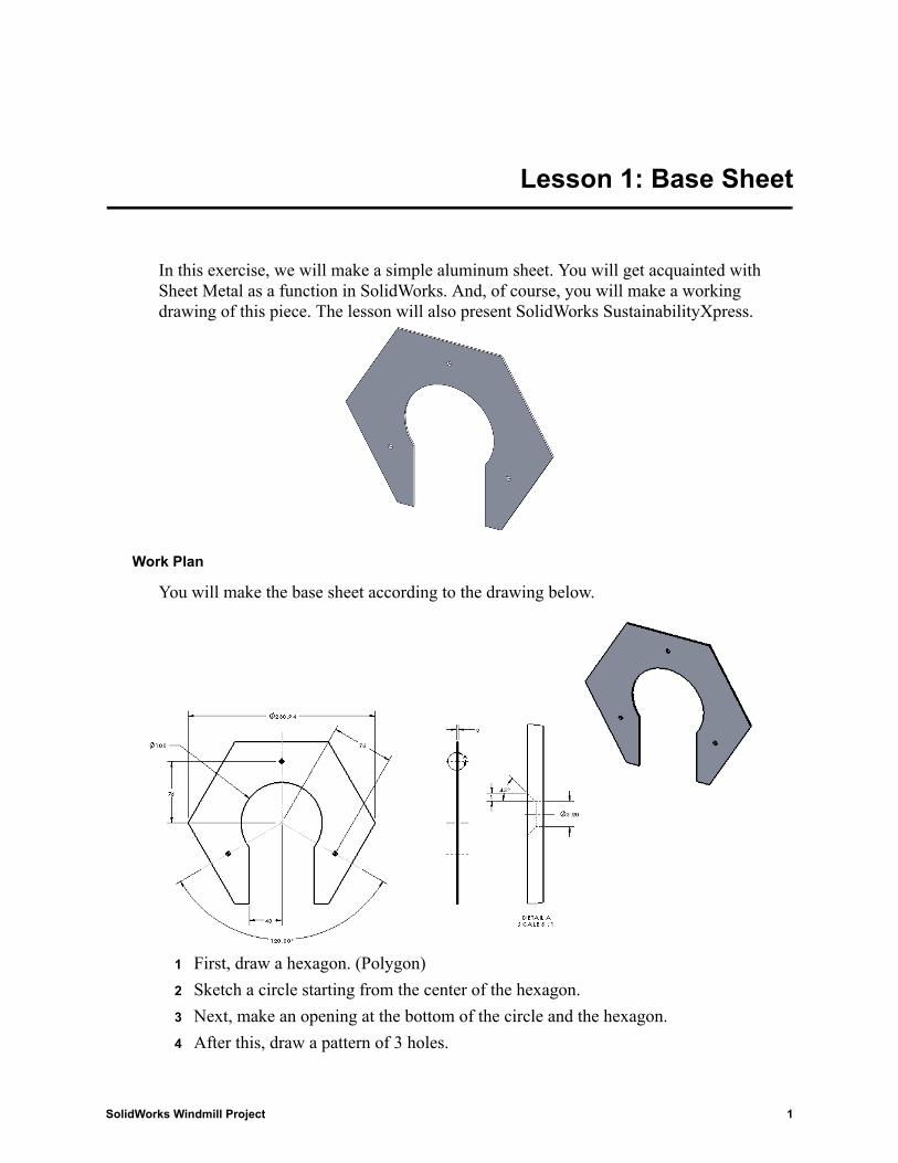
Lesson 1: Base Sheet
In this exercise, we will make a simple aluminum sheet. You will get acquainted with Sheet Metal as a function in SolidWorks. And, of course, you will make a working drawing of this piece. The lesson will also present SolidWorks SustainabilityXpress.
Work Plan
You will make the base sheet according to the drawing below.
1 First, draw a hexagon. (Polygon)
2 Sketch a circle starting from the center of the hexagon.
3 Next, make an opening at the bottom of the circle and the hexagon.
4 After this, draw a pattern of 3 holes.
SolidWorks Windmill Project 1
Lesson 1: Base Sheet
5 Finally, make a working drawing for use in the workshop.
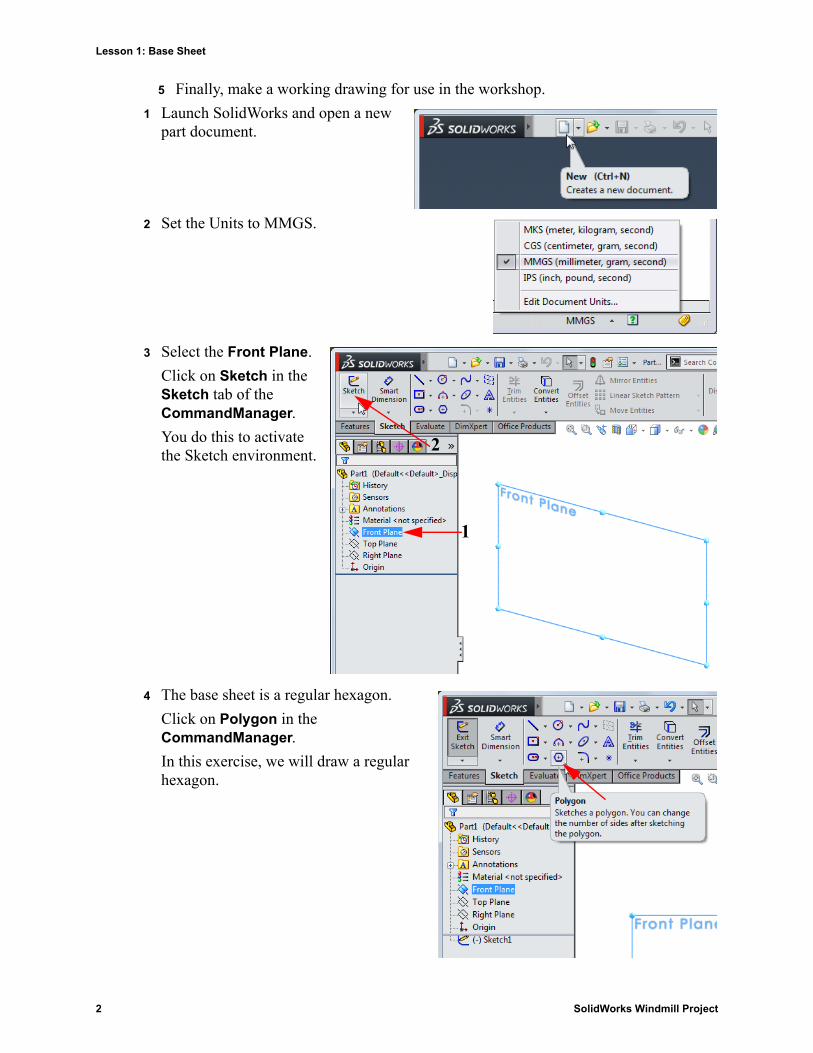
1 Launch SolidWorks and open a new part document.
2 Set the Units to MMGS.
3 Select the Front Plane.
Click on Sketch in the Sketch tab of the CommandManager.
You do this to activate the Sketch environment.
4 The base sheet is a regular hexagon.
Click on Polygon in the CommandManager.
In this exercise, we will draw a regular hexagon.
1
2
2 SolidWorks Windmill Project
Lesson 1: Base Sheet
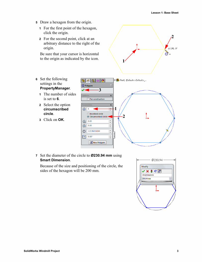
5 Draw a hexagon from the origin.
1 For the first point of the hexagon, click the origin.
2 For the second point, click at an arbitrary distance to the right of the origin.
Be sure that your cursor is horizontal to the origin as indicated by the icon.
6 Set the following settings in the PropertyManager.
1 The number of sides is set to 6.
2 Select the option circumscribed circle.
3 Click on OK.
7 Set the diameter of the circle to Ø230.94 mm using Smart Dimension.
Because of the size and positioning of the circle, the sides of the hexagon will be 200 mm.
1
2
12
3
SolidWorks Windmill Project 3
Lesson 1: Base Sheet
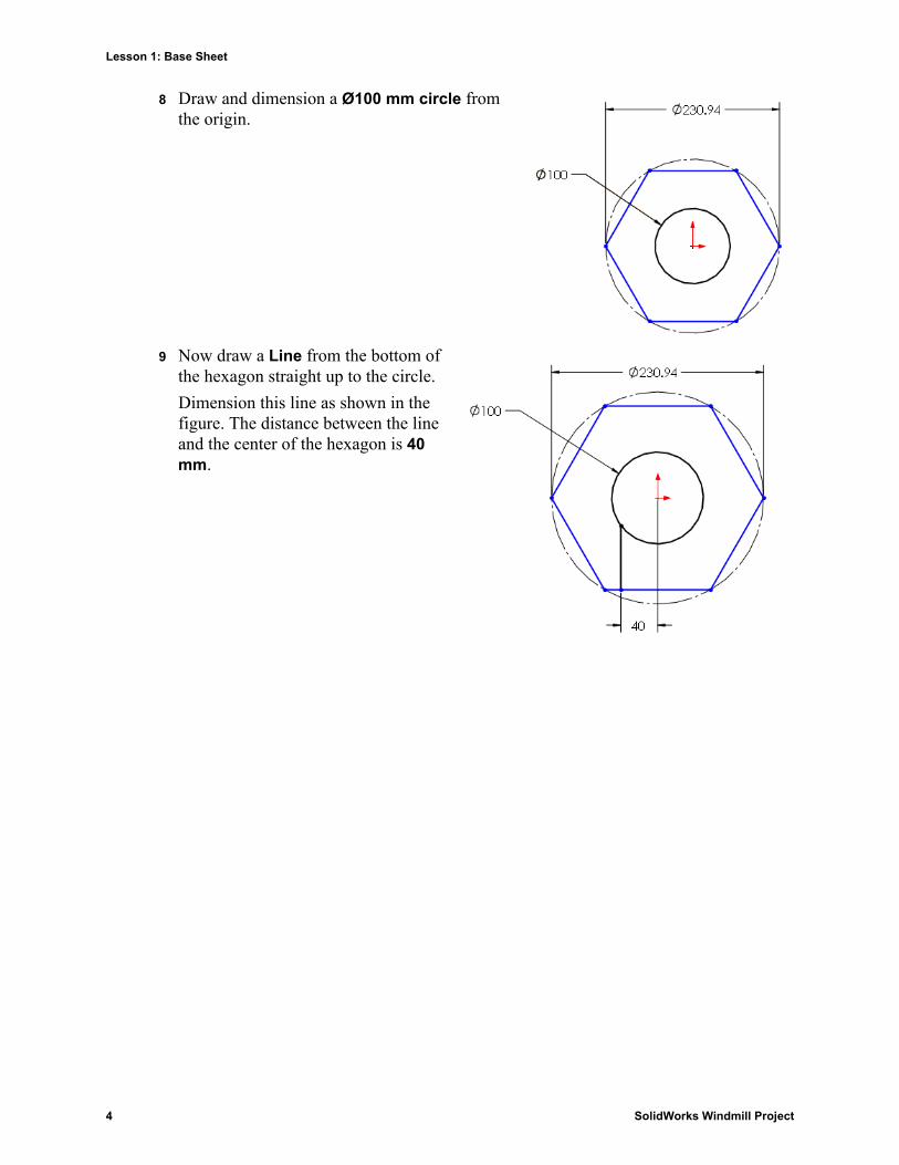
8 Draw and dimension a Ø100 mm circle from the origin.
9 Now draw a Line from the bottom of the hexagon straight up to the circle.
Dimension this line as shown in the figure. The distance between the line and the center of the hexagon is 40 mm.
4 SolidWorks Windmill Project
Lesson 1: Base Sheet
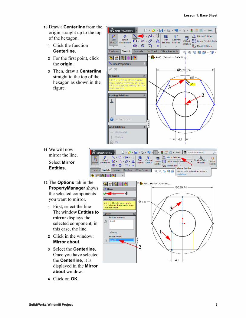
10 Draw a Centerline from the origin straight up to the top of the hexagon.
1 Click the function Centerline.
2 For the first point, click the origin.
3 Then, draw a Centerline straight to the top of the hexagon as shown in the figure.
11 We will now mirror the line.
Select Mirror Entities.
12 The Options tab in the PropertyManager shows the selected components you want to mirror.
1 First, select the lineThe window Entities to mirror displays the selected component, in this case, the line.
2 Click in the window: Mirror about.
3 Select the Centerline.Once you have selected the Centerline, it is displayed in the Mirror about window.
4 Click on OK.
1
23
1
2
3
4
SolidWorks Windmill Project 5
Lesson 1: Base Sheet
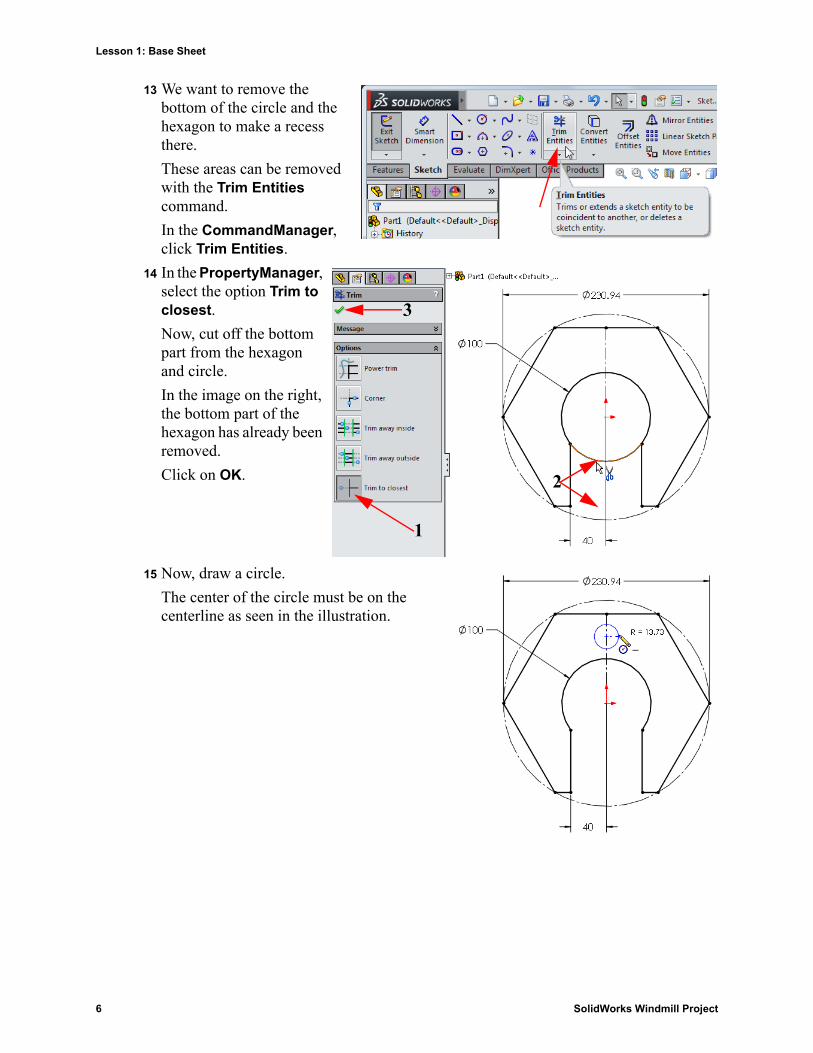
13 We want to remove the bottom of the circle and the hexagon to make a recess there.
These areas can be removed with the Trim Entities command.
In the CommandManager, click Trim Entities.
14 In the PropertyManager, select the option Trim to closest.
Now, cut off the bottom part from the hexagon and circle.
In the image on the right, the bottom part of the hexagon has already been removed.
Click on OK.
15 Now, draw a circle.
The center of the circle must be on the centerline as seen in the illustration.
1
2
3
6 SolidWorks Windmill Project
Lesson 1: Base Sheet
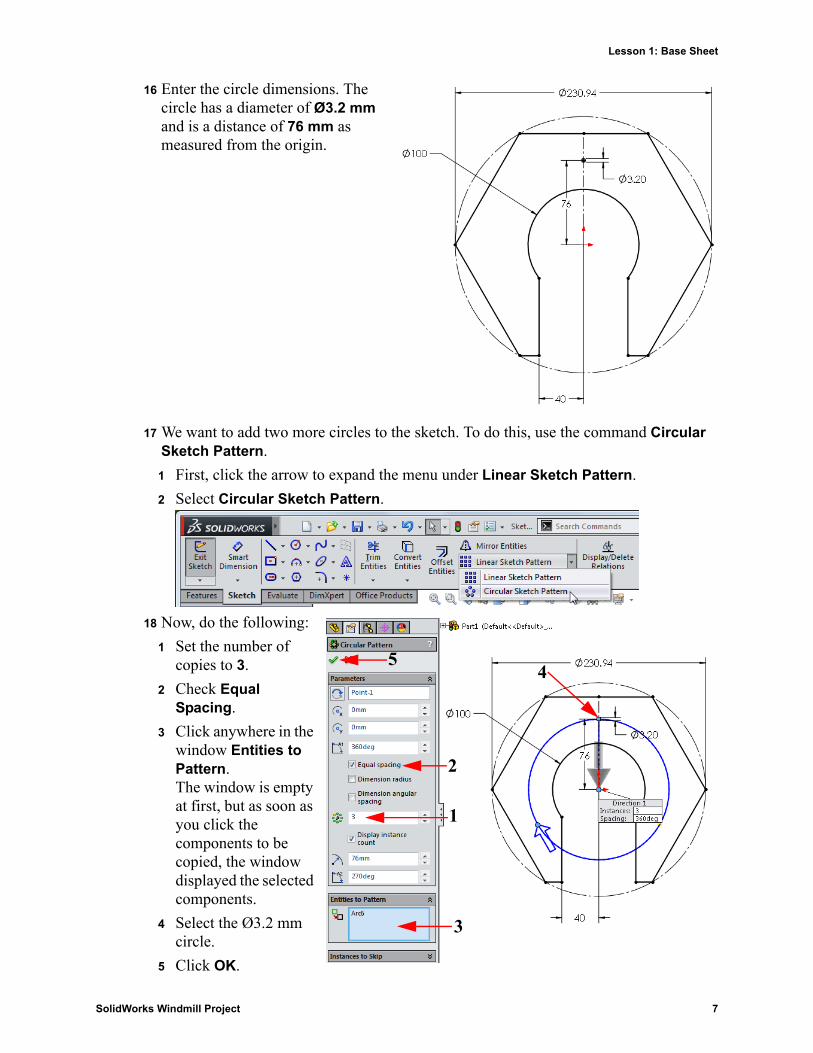
16 Enter the circle dimensions. The circle has a diameter of Ø3.2 mm and is a distance of 76 mm as measured from the origin.
17 We want to add two more circles to the sketch. To do this, use the command Circular Sketch Pattern.
1 First, click the arrow to expand the menu under Linear Sketch Pattern.
2 Select Circular Sketch Pattern.
18 Now, do the following:
1 Set the number of copies to 3.
2 Check Equal Spacing.
3 Click anywhere in the window Entities to Pattern.The window is empty at first, but as soon as you click the components to be copied, the window displayed the selected components.
4 Select the Ø3.2 mm circle.
5 Click OK.
1
2
3
45
SolidWorks Windmill Project 7
Lesson 1: Base Sheet
Tip: You have just found out that using Linear Sketch Pattern or Circular Sketch Pattern will considerably reduce your drawing time.You can easily add objects (lines, circles, rectangles, etc.) according to a specific pattern.
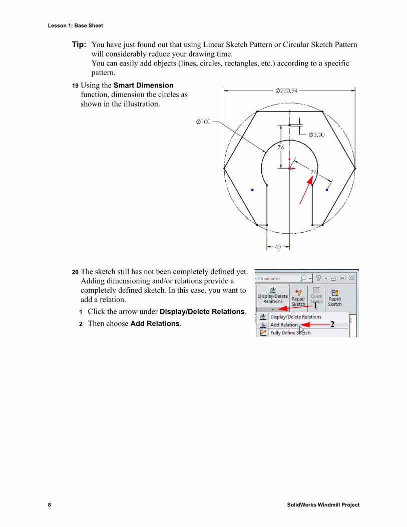
19 Using the Smart Dimension function, dimension the circles as shown in the illustration.
20 The sketch still has not been completely defined yet. Adding dimensioning and/or relations provide a completely defined sketch. In this case, you want to add a relation.
1 Click the arrow under Display/Delete Relations.
2 Then choose Add Relations.
1
2
8 SolidWorks Windmill Project
Lesson 1: Base Sheet
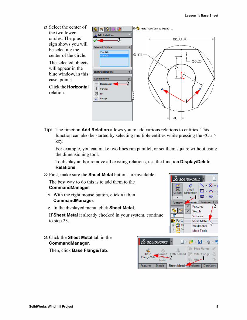
21 Select the center of the two lower circles. The plus sign shows you will be selecting the center of the circle.
The selected objects will appear in the blue window, in this case, points.
Click the Horizontal relation.
Tip: The function Add Relation allows you to add various relations to entities. This function can also be started by selecting multiple entities while pressing the <Ctrl> key.
For example, you can make two lines run parallel, or set them square without using the dimensioning tool.
To display and/or remove all existing relations, use the function Display/Delete Relations.
22 First, make sure the Sheet Metal buttons are available.
The best way to do this is to add them to the CommandManager.
1 With the right mouse button, click a tab in CommandManager.
2 In the displayed menu, click Sheet Metal.
If Sheet Metal it already checked in your system, continue to step 23.
23 Click the Sheet Metal tab in the CommandManager.
Then, click Base Flange/Tab.
1
2
3
12
12
SolidWorks Windmill Project 9
Lesson 1: Base Sheet
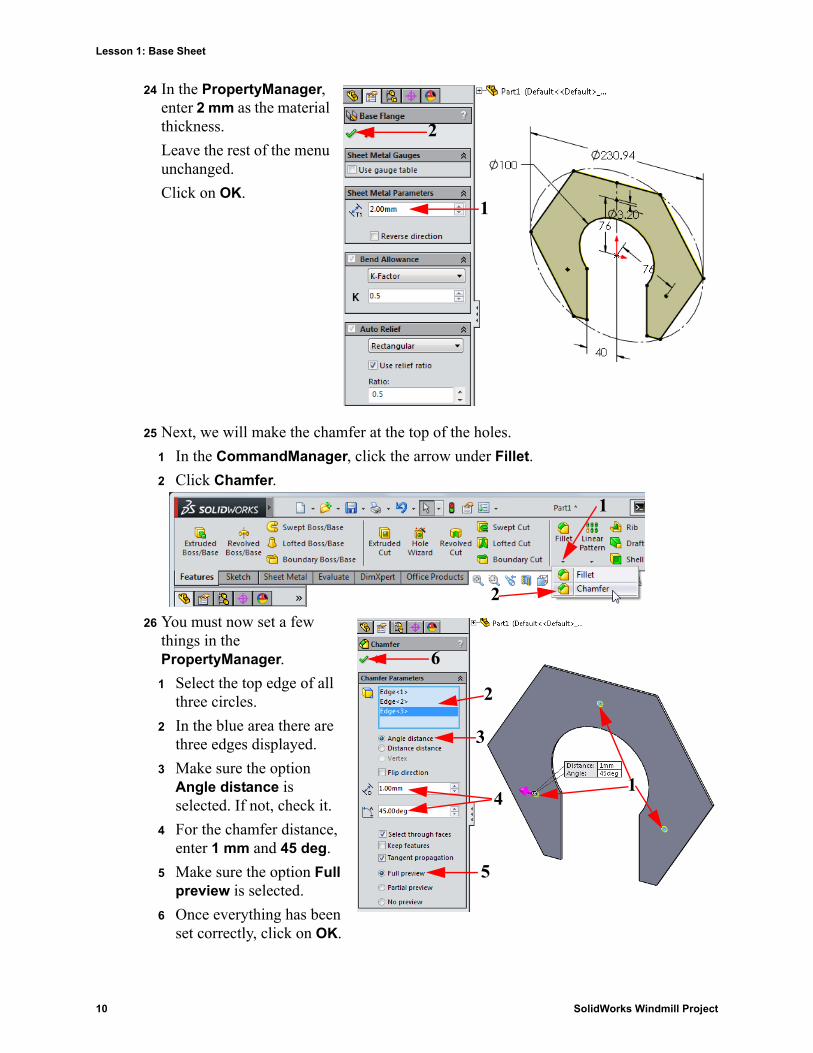
24 In the PropertyManager, enter 2 mm as the material thickness.
Leave the rest of the menu unchanged.
Click on OK.
25 Next, we will make the chamfer at the top of the holes.
1 In the CommandManager, click the arrow under Fillet.
2 Click Chamfer.
26 You must now set a few things in the PropertyManager.
1 Select the top edge of all three circles.
2 In the blue area there are three edges displayed.
3 Make sure the option Angle distance is selected. If not, check it.
4 For the chamfer distance, enter 1 mm and 45 deg.
5 Make sure the option Full preview is selected.
6 Once everything has been set correctly, click on OK.
1
2
1
2
1
2
3
4
5
6
10 SolidWorks Windmill Project
Lesson 1: Base Sheet
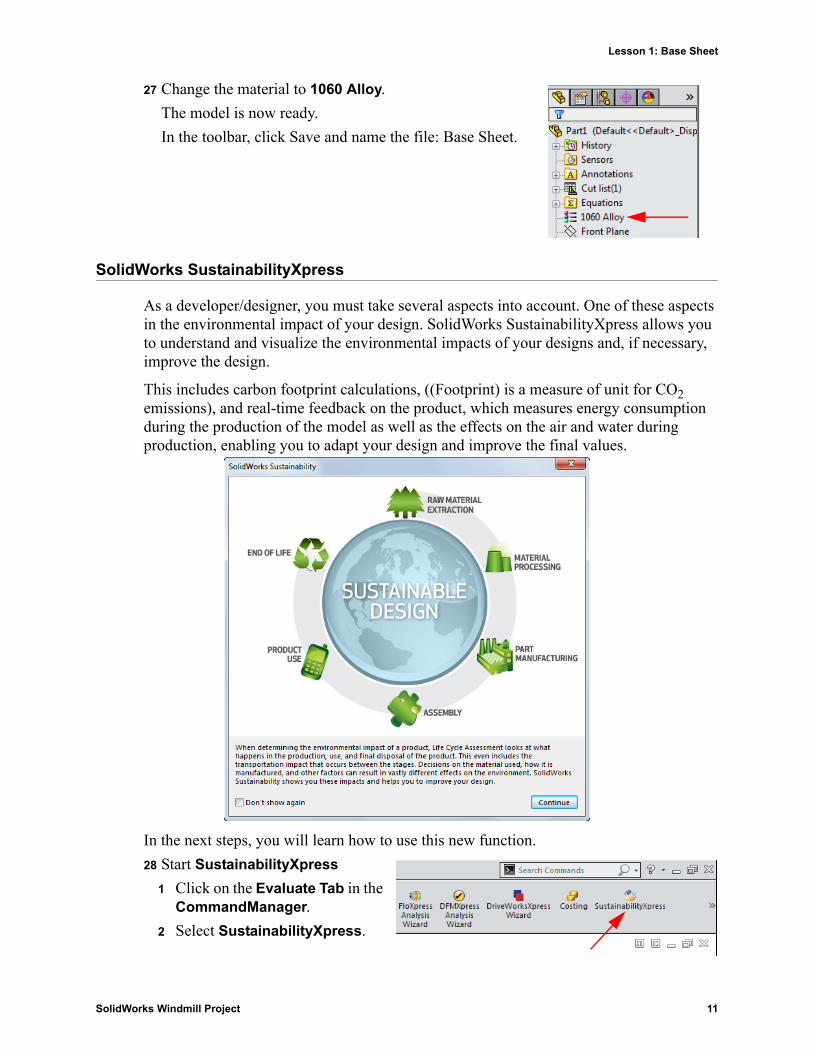
27 Change the material to 1060 Alloy.
The model is now ready.
In the toolbar, click Save and name the file: Base Sheet.
SolidWorks SustainabilityXpress
As a developer/designer, you must take several aspects into account. One of these aspects in the environmental impact of your design. SolidWorks SustainabilityXpress allows you to understand and visualize the environmental impacts of your designs and, if necessary, improve the design.
This includes carbon footprint calculations, ((Footprint) is a measure of unit for CO2 emissions), and real-time feedback on the product, which measures energy consumption during the production of the model as well as the effects on the air and water during production, enabling you to adapt your design and improve the final values.
In the next steps, you will learn how to use this new function.
28 Start SustainabilityXpress
1 Click on the Evaluate Tab in the CommandManager.
2 Select SustainabilityXpress.
SolidWorks Windmill Project 11
Lesson 1: Base Sheet
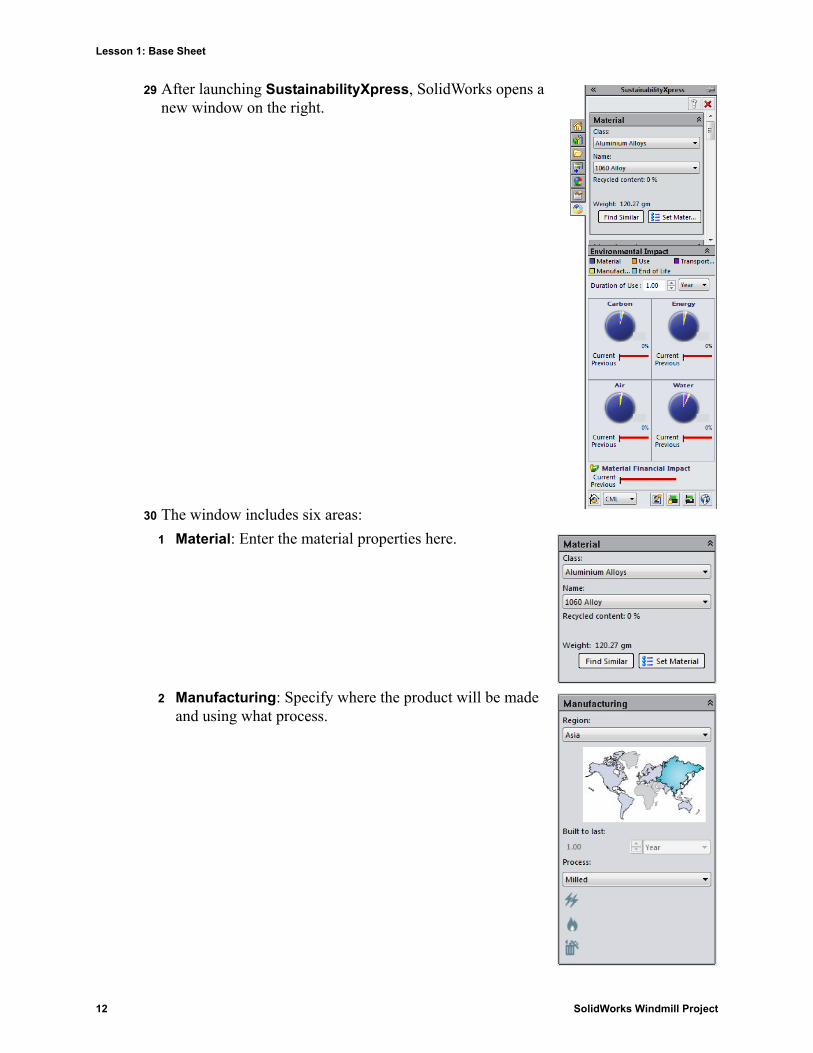
29 After launching SustainabilityXpress, SolidWorks opens a new window on the right.
30 The window includes six areas:
1 Material: Enter the material properties here.
2 Manufacturing: Specify where the product will be made and using what process.
12 SolidWorks Windmill Project
Lesson 1: Base Sheet
3 Use: Specify the region where the product will be used.
4 Transportation: The method used to move the product from where it is manufactured to where it is used.
5 End of Life: The percentage of the product that gets recycled, incinerated, or put in a landfill.
6 Environmental Impacts: Four diagrams are displayed here. They show the environmental impact of production and transportation.
31 Let us now take a more detailed look at how SustainabilityXpress works.
1 In step 27, the material has already been defines as Aluminum 1060 Alloy. The software copied and pasted this automatically.
SolidWorks Windmill Project 13
Lesson 1: Base Sheet
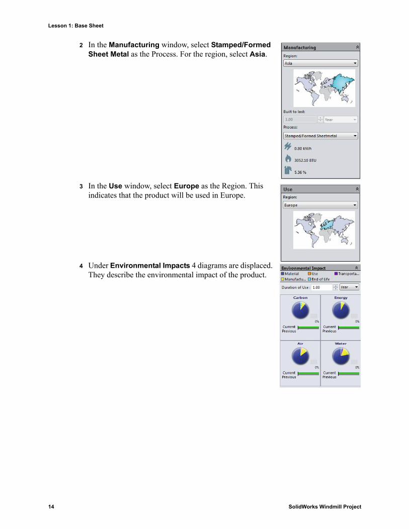
2 In the Manufacturing window, select Stamped/Formed Sheet Metal as the Process. For the region, select Asia.
3 In the Use window, select Europe as the Region. This indicates that the product will be used in Europe.
4 Under Environmental Impacts 4 diagrams are displaced. They describe the environmental impact of the product.
14 SolidWorks Windmill Project
Lesson 1: Base Sheet
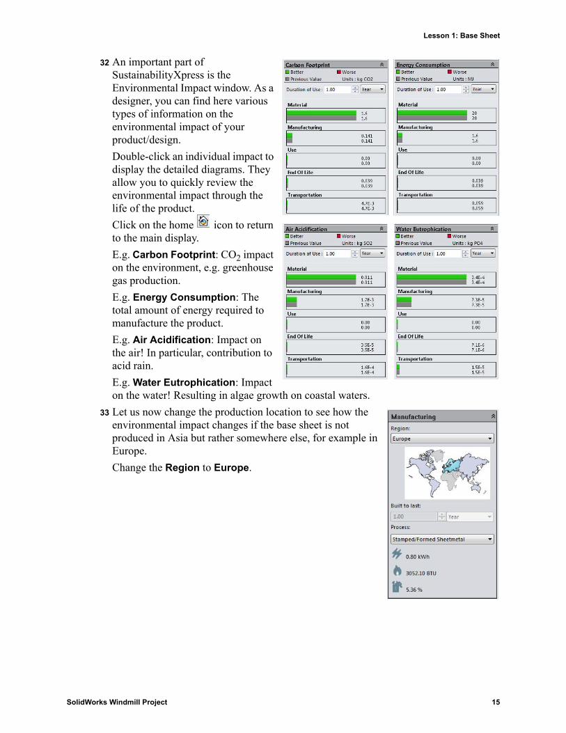
32 An important part of SustainabilityXpress is the Environmental Impact window. As a designer, you can find here various types of information on the environmental impact of your product/design.
Double-click an individual impact to display the detailed diagrams. They allow you to quickly review the environmental impact through the life of the product.
Click on the home icon to return to the main display.
E.g. Carbon Footprint: CO2 impact on the environment, e.g. greenhouse gas production.
E.g. Energy Consumption: The total amount of energy required to manufacture the product.
E.g. Air Acidification: Impact on the air! In particular, contribution to acid rain.
E.g. Water Eutrophication: Impact on the water! Resulting in algae growth on coastal waters.
33 Let us now change the production location to see how the environmental impact changes if the base sheet is not produced in Asia but rather somewhere else, for example in Europe.
Change the Region to Europe.
SolidWorks Windmill Project 15
Lesson 1: Base Sheet
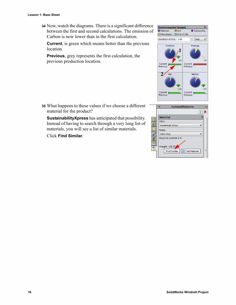
34 Now, watch the diagrams. There is a significant difference between the first and second calculations. The emission of Carbon is now lower than in the first calculation.
Current, is green which means better than the previous location.
Previous, grey represents the first calculation, the previous production location.
35 What happens to these values if we choose a different material for the product?
SustainabilityXpress has anticipated that possibility. Instead of having to search through a very long list of materials, you will see a list of similar materials.
Click Find Similar.
1
2
16 SolidWorks Windmill Project
Lesson 1: Base Sheet
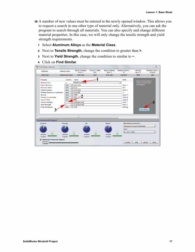
36 A number of new values must be entered in the newly opened window. This allows you to request a search in one other type of material only. Alternatively, you can ask the program to search through all materials. You can also specify and change different material properties. In this case, we will only change the tensile strength and yield strength requirements.
1 Select Aluminum Alloys as the Material Class.
2 Next to Tensile Strength, change the condition to greater than >.
3 Next to Yield Strength, change the condition to similar to ~.
4 Click on Find Similar.
1
2
3
4
SolidWorks Windmill Project 17
Lesson 1: Base Sheet
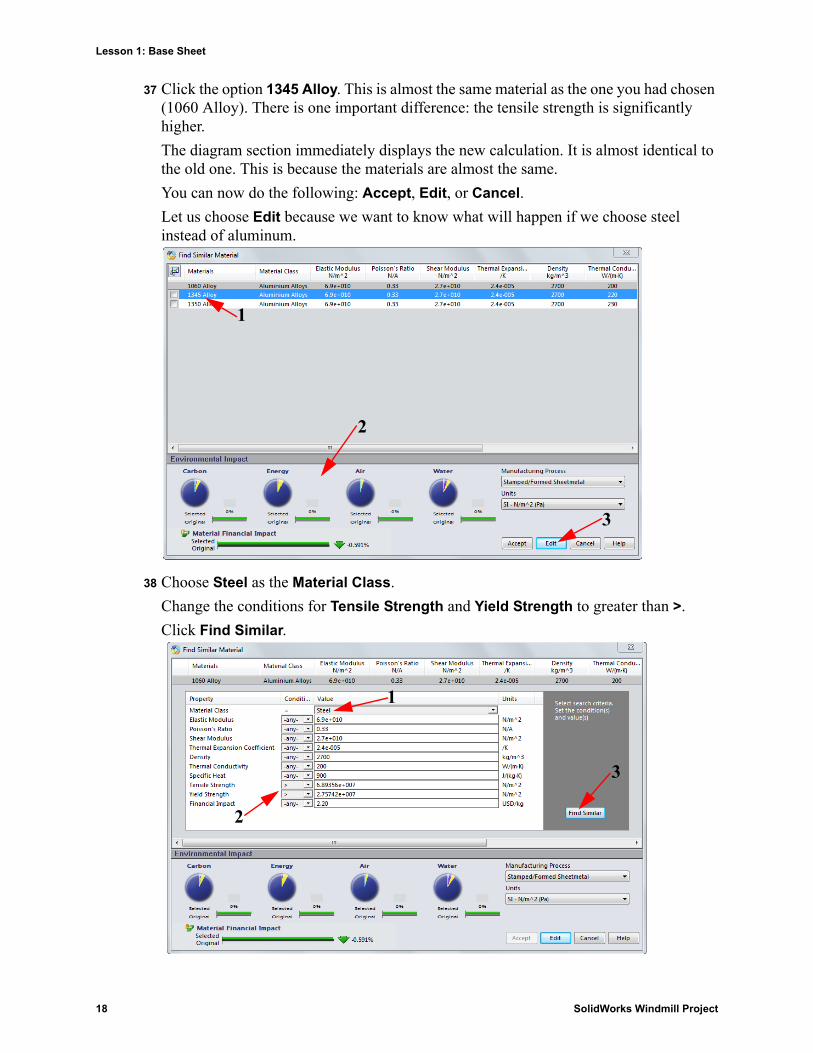
37 Click the option 1345 Alloy. This is almost the same material as the one you had chosen (1060 Alloy). There is one important difference: the tensile strength is significantly higher.
The diagram section immediately displays the new calculation. It is almost identical to the old one. This is because the materials are almost the same.
You can now do the following: Accept, Edit, or Cancel.
Let us choose Edit because we want to know what will happen if we choose steel instead of aluminum.
38 Choose Steel as the Material Class.
Change the conditions for Tensile Strength and Yield Strength to greater than >.
Click Find Similar.
1
2
3
1
2
3
18 SolidWorks Windmill Project
Lesson 1: Base Sheet
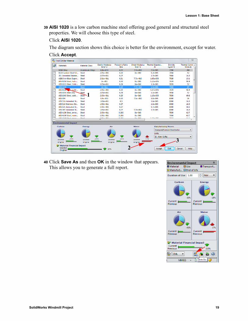
39 AISI 1020 is a low carbon machine steel offering good general and structural steel properties. We will choose this type of steel.
Click AISI 1020.
The diagram section shows this choice is better for the environment, except for water.
Click Accept.
40 Click Save As and then OK in the window that appears. This allows you to generate a full report.
1
23
SolidWorks Windmill Project 19
Lesson 1: Base Sheet
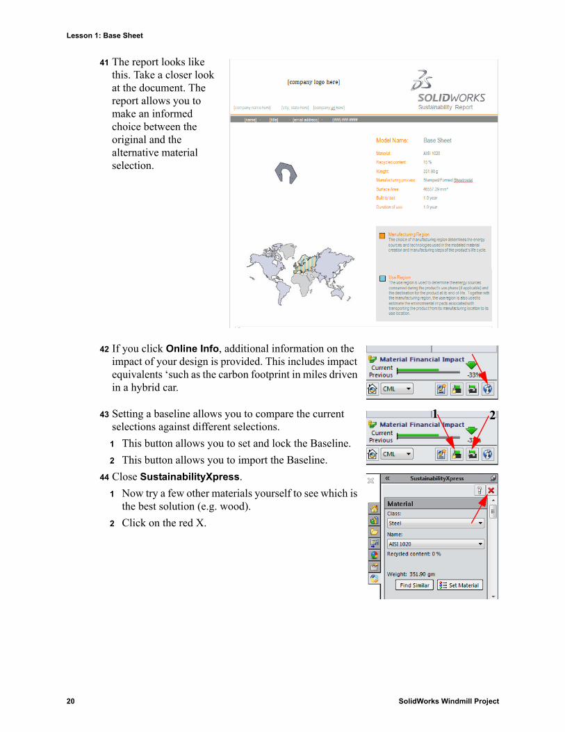
41 The report looks like this. Take a closer look at the document. The report allows you to make an informed choice between the original and the alternative material selection.
42 If you click Online Info, additional information on the impact of your design is provided. This includes impact equivalents ‘such as the carbon footprint in miles driven in a hybrid car.
43 Setting a baseline allows you to compare the current selections against different selections.
1 This button allows you to set and lock the Baseline.
2 This button allows you to import the Baseline.
44 Close SustainabilityXpress.
1 Now try a few other materials yourself to see which is the best solution (e.g. wood).
2 Click on the red X.
1 2
20 SolidWorks Windmill Project
Lesson 1: Base Sheet
Base Sheet Drawing
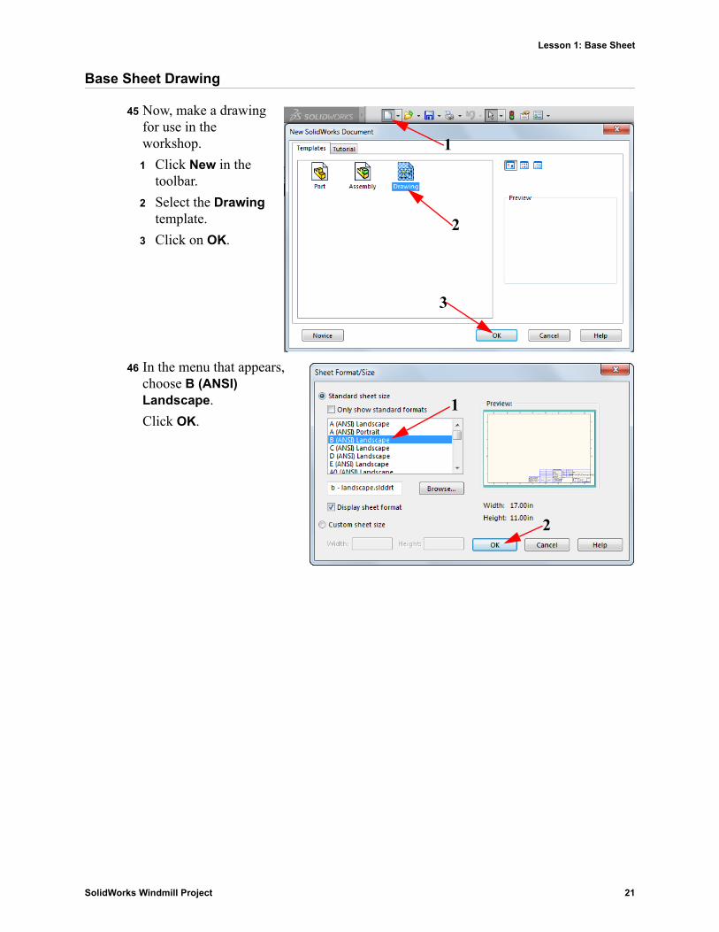
45 Now, make a drawing for use in the workshop.
1 Click New in the toolbar.
2 Select the Drawing template.
3 Click on OK.
46 In the menu that appears, choose B (ANSI) Landscape.
Click OK.
1
2
3
1
2
SolidWorks Windmill Project 21
Lesson 1: Base Sheet
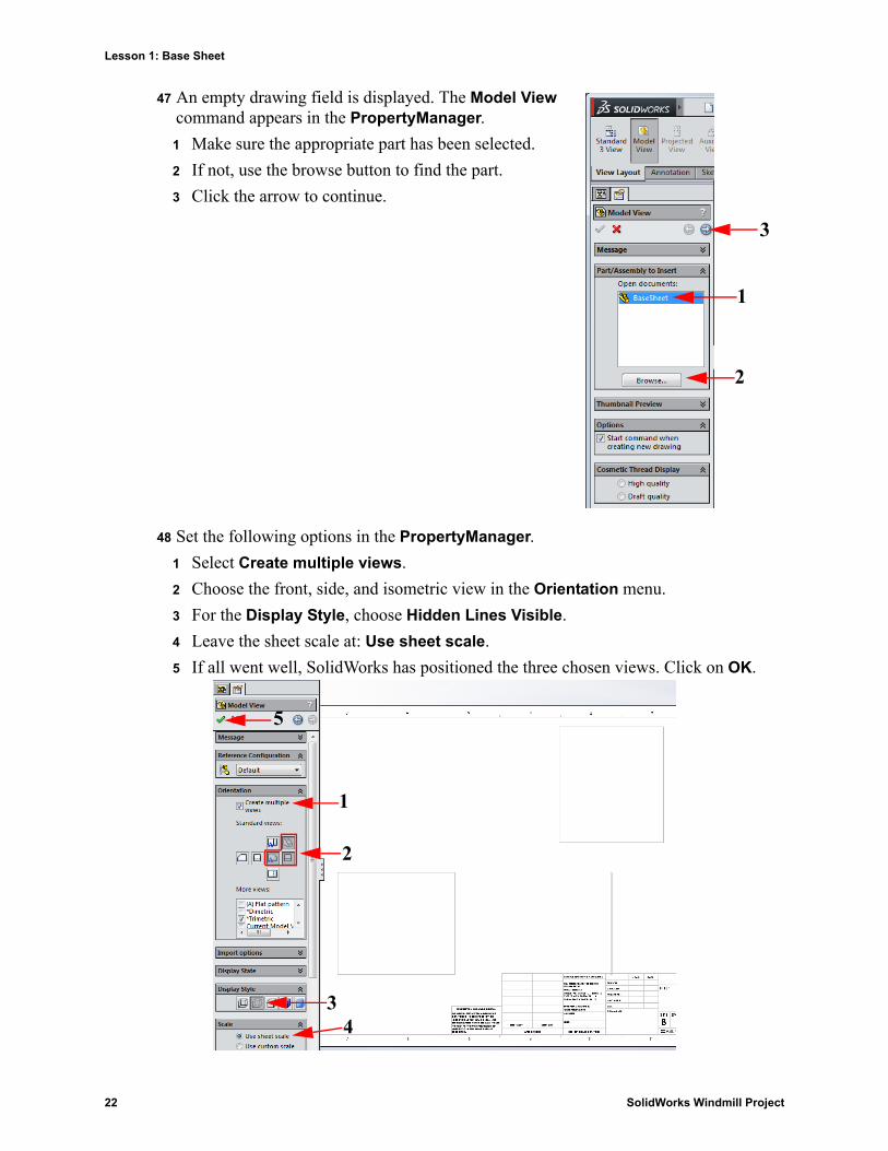
47 An empty drawing field is displayed. The Model View command appears in the PropertyManager.
1 Make sure the appropriate part has been selected.
2 If not, use the browse button to find the part.
3 Click the arrow to continue.
48 Set the following options in the PropertyManager.
1 Select Create multiple views.
2 Choose the front, side, and isometric view in the Orientation menu.
3 For the Display Style, choose Hidden Lines Visible.
4 Leave the sheet scale at: Use sheet scale.
5 If all went well, SolidWorks has positioned the three chosen views. Click on OK.
1
2
3
1
2
34
5
22 SolidWorks Windmill Project
Lesson 1: Base Sheet
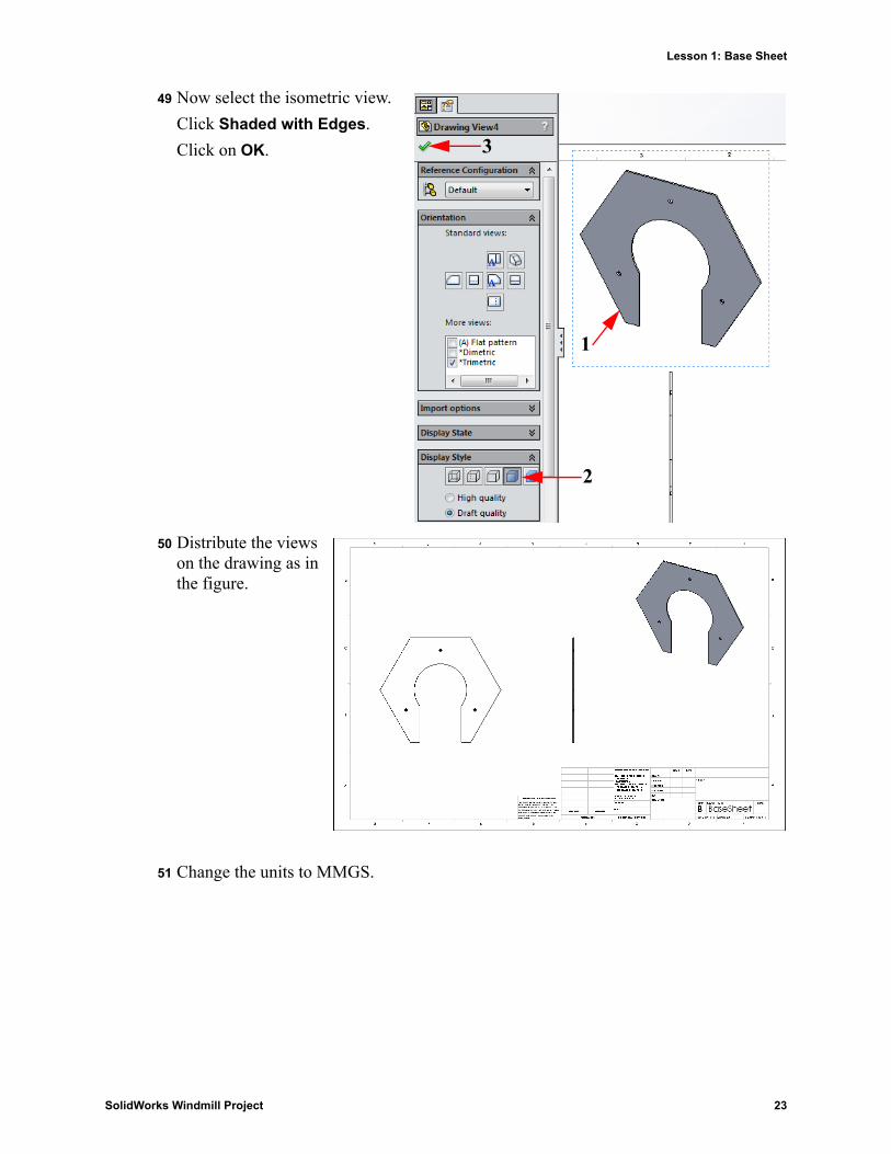
49 Now select the isometric view.
Click Shaded with Edges.
Click on OK.
50 Distribute the views on the drawing as in the figure.
51 Change the units to MMGS.
1
2
3
SolidWorks Windmill Project 23
Lesson 1: Base Sheet
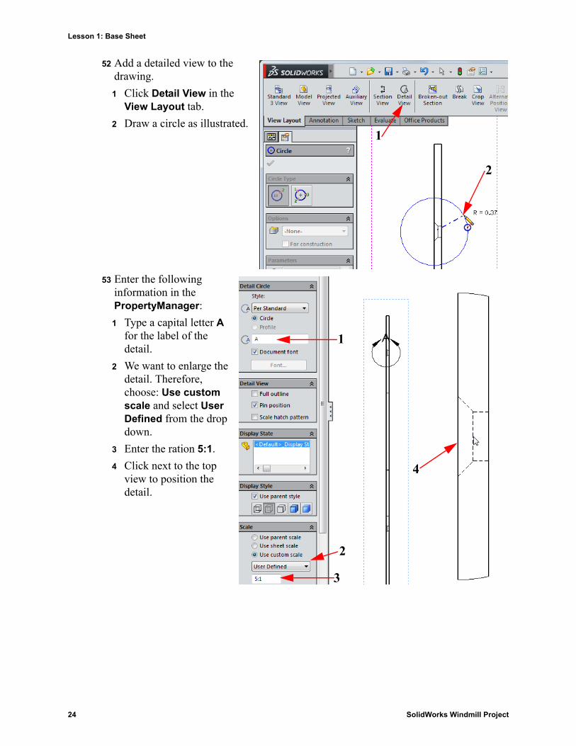
52 Add a detailed view to the drawing.
1 Click Detail View in the View Layout tab.
2 Draw a circle as illustrated.
53 Enter the following information in the PropertyManager:
1 Type a capital letter A for the label of the detail.
2 We want to enlarge the detail. Therefore, choose: Use custom scale and select User Defined from the drop down.
3 Enter the ration 5:1.
4 Click next to the top view to position the detail.
1
2
1
2
3
4
24 SolidWorks Windmill Project

Lesson 1: Base Sheet
54 Draw a centerline from the center of the circle straight up.
1 Click the arrow next to the line tool to show the Centerline function and select it.
2 Click in the middle of the circle; draw the Centerline and click anywhere above the model.
55 You will add two more lines using the function Circular Sketch Pattern.
1 Click the drop down under Linear Sketch Pattern and select Circular Sketch Pattern.
2 Enter 3 as a quantity.
3 Click in the Entities to Pattern window and select the vertical line you have just drawn.
1
2
1
2
3
3
SolidWorks Windmill Project 25
Lesson 1: Base Sheet
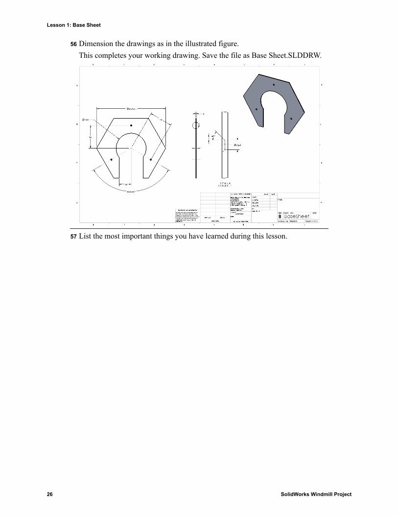
56 Dimension the drawings as in the illustrated figure.
This completes your working drawing. Save the file as Base Sheet.SLDDRW.
57 List the most important things you have learned during this lesson.
26 SolidWorks Windmill Project
Lesson 2: Windmill Assembly
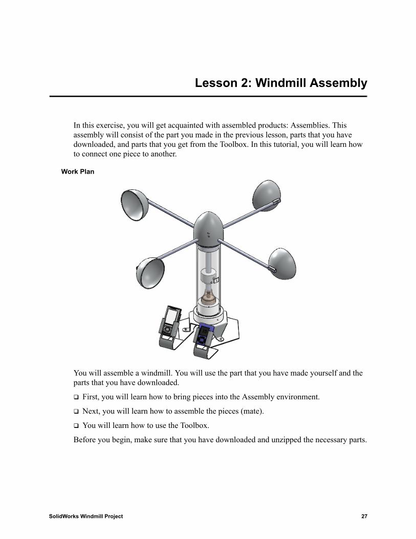
In this exercise, you will get acquainted with assembled products: Assemblies. This assembly will consist of the part you made in the previous lesson, parts that you have downloaded, and parts that you get from the Toolbox. In this tutorial, you will learn how to connect one piece to another.
Work Plan
You will assemble a windmill. You will use the part that you have made yourself and the parts that you have downloaded.
First, you will learn how to bring pieces into the Assembly environment.
Next, you will learn how to assemble the pieces (mate).
You will learn how to use the Toolbox.
Before you begin, make sure that you have downloaded and unzipped the necessary parts.
SolidWorks Windmill Project 27
Lesson 2: Windmill Assembly
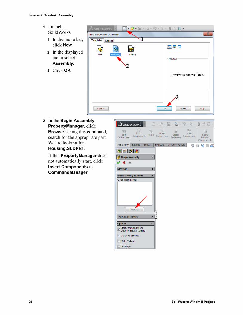
1 Launch SolidWorks.
1 In the menu bar, click New.
2 In the displayed menu select Assembly.
3 Click OK.
2 In the Begin Assembly PropertyManager, click Browse. Using this command, search for the appropriate part. We are looking for Housing.SLDPRT.
If this PropertyManager does not automatically start, click Insert Components in CommandManager.
1
2
3
28 SolidWorks Windmill Project
Lesson 2: Windmill Assembly
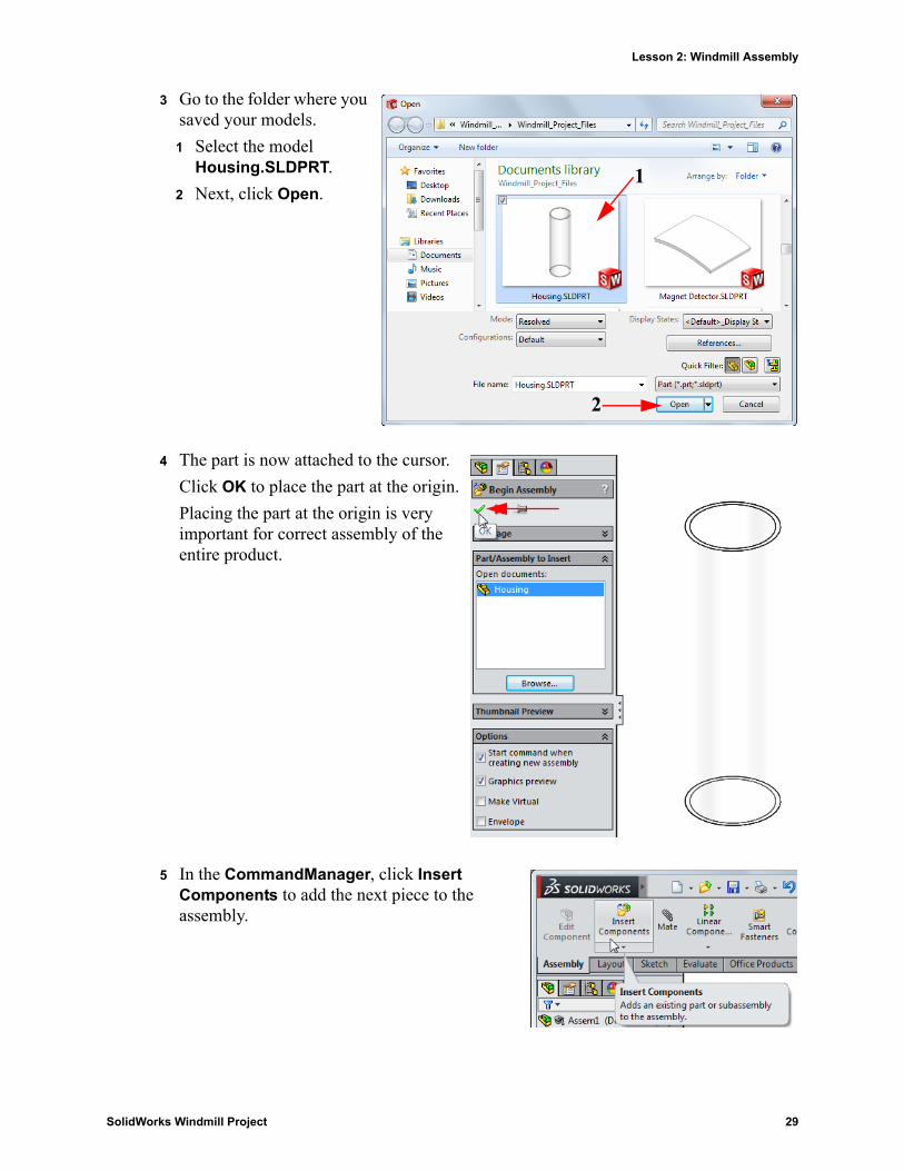
3 Go to the folder where you saved your models.
1 Select the model Housing.SLDPRT.
2 Next, click Open.
4 The part is now attached to the cursor.
Click OK to place the part at the origin.
Placing the part at the origin is very important for correct assembly of the entire product.
5 In the CommandManager, click Insert Components to add the next piece to the assembly.
1
2
SolidWorks Windmill Project 29
Lesson 2: Windmill Assembly
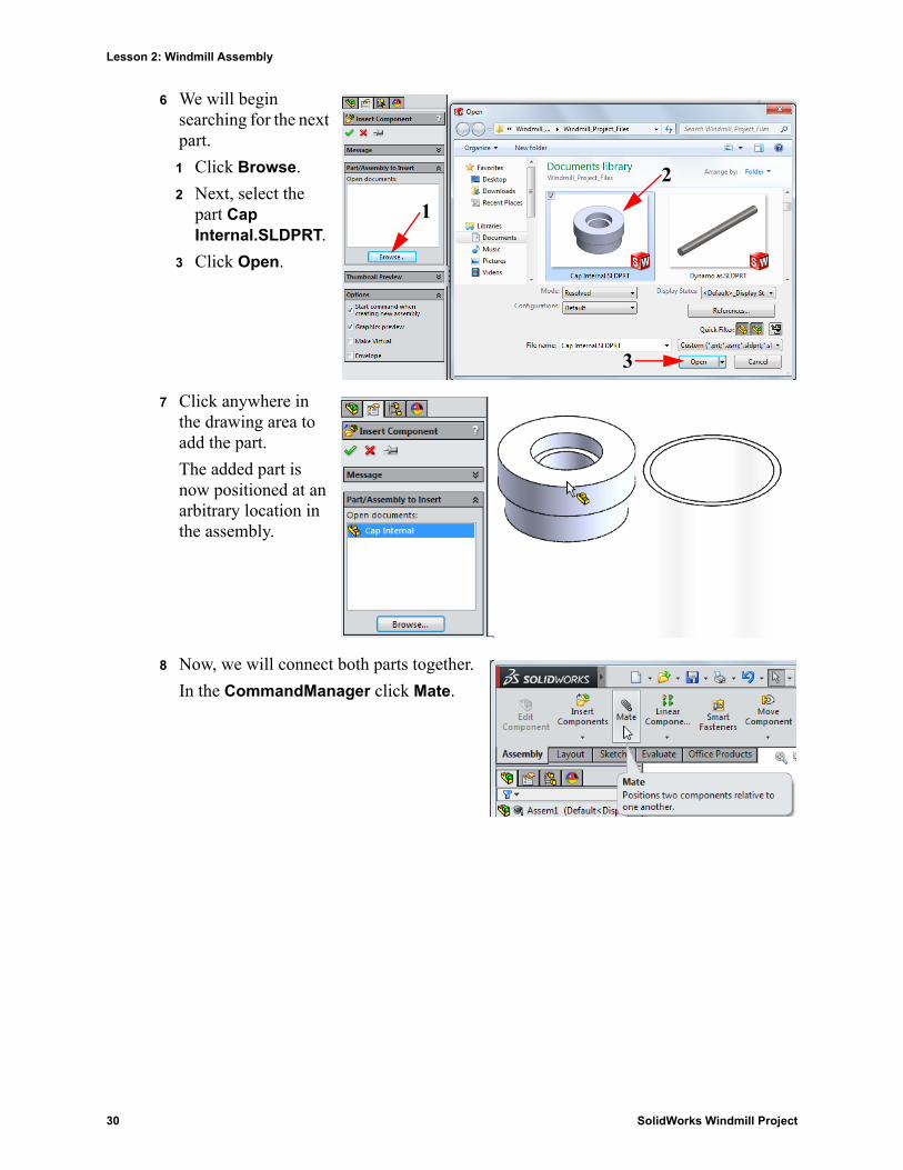
6 We will begin searching for the next part.
1 Click Browse.
2 Next, select the part Cap Internal.SLDPRT.
3 Click Open.
7 Click anywhere in the drawing area to add the part.
The added part is now positioned at an arbitrary location in the assembly.
8 Now, we will connect both parts together.
In the CommandManager click Mate.
1
2
3
30 SolidWorks Windmill Project
Lesson 2: Windmill Assembly
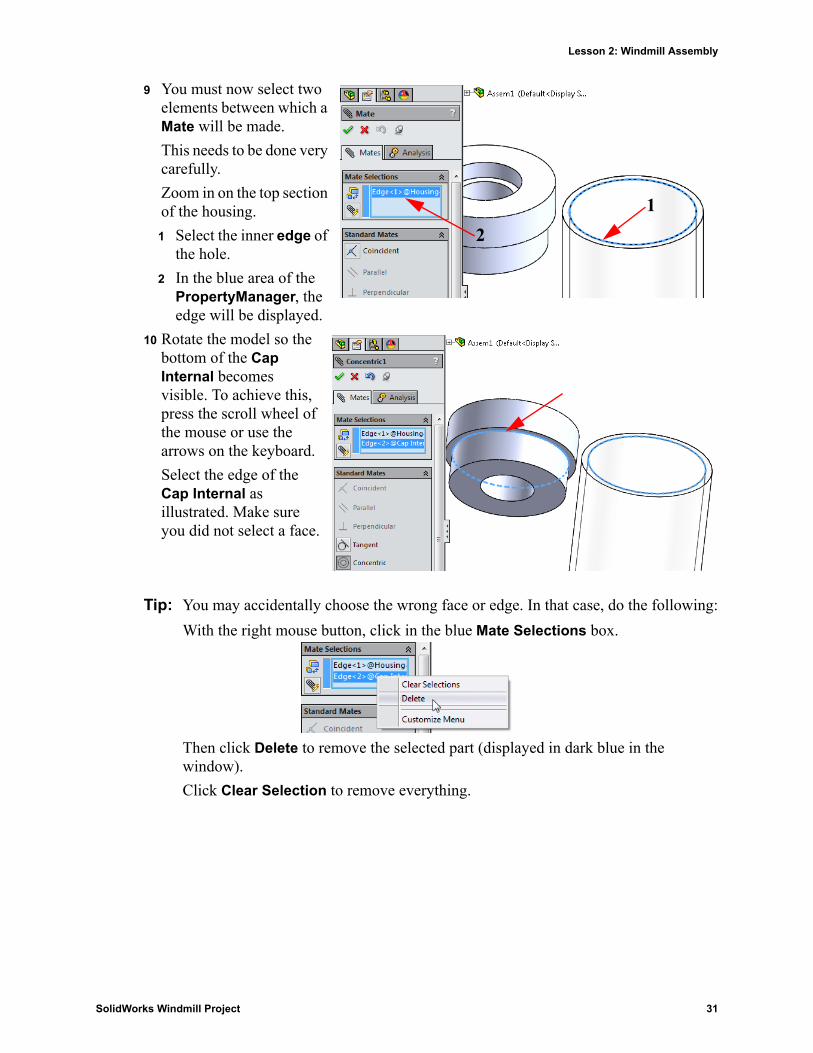
9 You must now select two elements between which a Mate will be made.
This needs to be done very carefully.
Zoom in on the top section of the housing.
1 Select the inner edge of the hole.
2 In the blue area of the PropertyManager, the edge will be displayed.
10 Rotate the model so the bottom of the Cap Internal becomes visible. To achieve this, press the scroll wheel of the mouse or use the arrows on the keyboard.
Select the edge of the Cap Internal as illustrated. Make sure you did not select a face.
Tip: You may accidentally choose the wrong face or edge. In that case, do the following:
With the right mouse button, click in the blue Mate Selections box.
Then click Delete to remove the selected part (displayed in dark blue in the window).
Click Clear Selection to remove everything.
12
SolidWorks Windmill Project 31
Lesson 2: Windmill Assembly
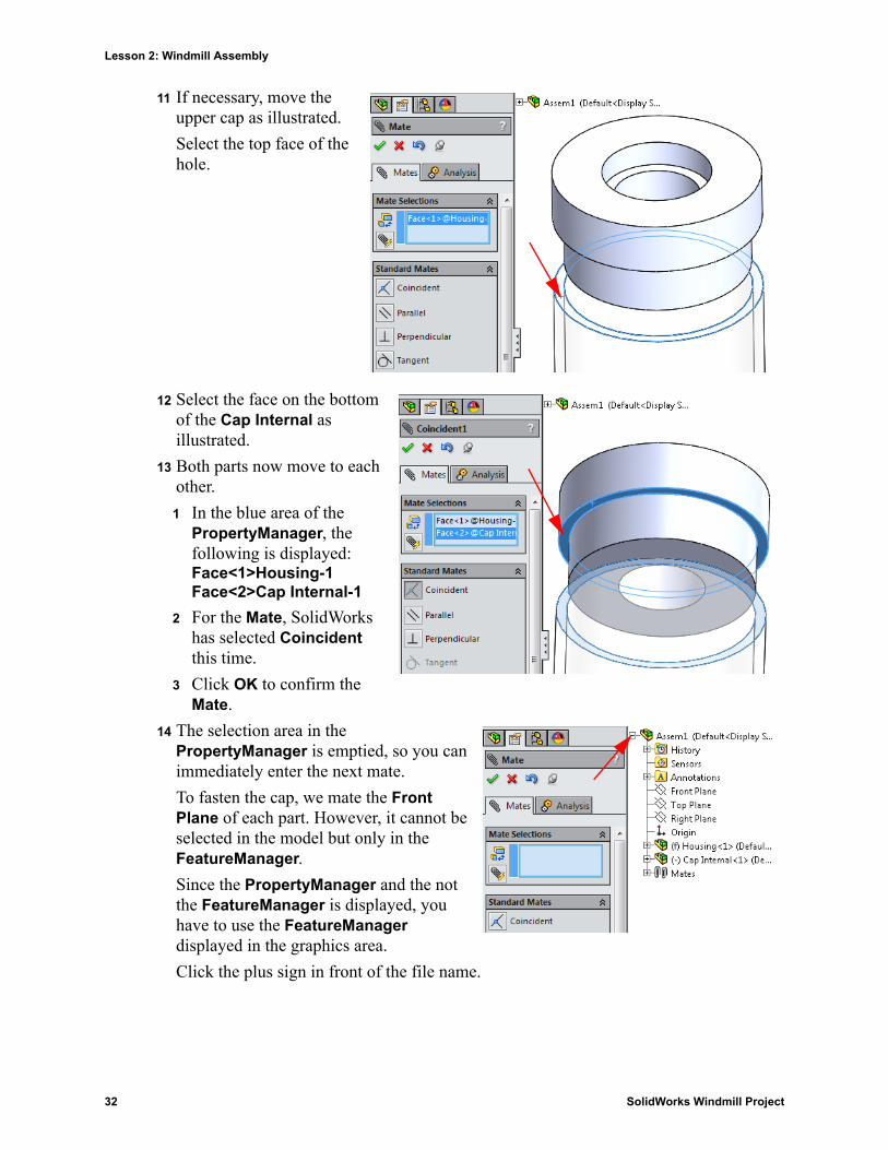
11 If necessary, move the upper cap as illustrated.
Select the top face of the hole.
12 Select the face on the bottom of the Cap Internal as illustrated.
13 Both parts now move to each other.
1 In the blue area of the PropertyManager, the following is displayed:Face<1>Housing-1Face<2>Cap Internal-1
2 For the Mate, SolidWorks has selected Coincident this time.
3 Click OK to confirm the Mate.
14 The selection area in the PropertyManager is emptied, so you can immediately enter the next mate.
To fasten the cap, we mate the Front Plane of each part. However, it cannot be selected in the model but only in the FeatureManager.
Since the PropertyManager and the not the FeatureManager is displayed, you have to use the FeatureManager displayed in the graphics area.
Click the plus sign in front of the file name.
32 SolidWorks Windmill Project
Lesson 2: Windmill Assembly
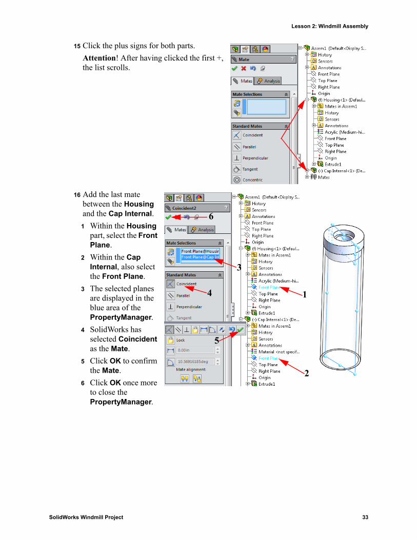
15 Click the plus signs for both parts.
Attention! After having clicked the first +, the list scrolls.
16 Add the last mate between the Housing and the Cap Internal.
1 Within the Housing part, select the Front Plane.
2 Within the Cap Internal, also select the Front Plane.
3 The selected planes are displayed in the blue area of the PropertyManager.
4 SolidWorks has selected Coincident as the Mate.
5 Click OK to confirm the Mate.
6 Click OK once more to close the PropertyManager.
1
2
3
4
5
6
SolidWorks Windmill Project 33

Lesson 2: Windmill Assembly
17 Now, add the other required parts.
You can do that by repeating steps 5 through 7.
Add the following parts:1 Wing Arm
2 Shaft
3 Base Sheet
4 Housing Base
5 Phone Holder
6 Windblade
7 Bottom End
8 Magnet Holder
9 Top End
18 We will now continue will the windmill assembly.
1 Drag the Base Sheet and the Housing Base somewhat downward.
2 Click the arrow below Move Component to open the scroll down menu.
3 Select Rotate Component.
19 Rotate the Housing Base as show in the figure.
Click OK.
1
2
3
4
5
6
7
8
9
1
2
3
12
34 SolidWorks Windmill Project
Lesson 2: Windmill Assembly
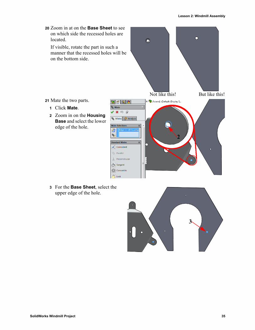
20 Zoom in at on the Base Sheet to see on which side the recessed holes are located.
If visible, rotate the part in such a manner that the recessed holes will be on the bottom side.
21 Mate the two parts.
1 Click Mate.
2 Zoom in on the Housing Base and select the lower edge of the hole.
3 For the Base Sheet, select the upper edge of the hole.
Not like this! But like this!
2
3
SolidWorks Windmill Project 35
Lesson 2: Windmill Assembly
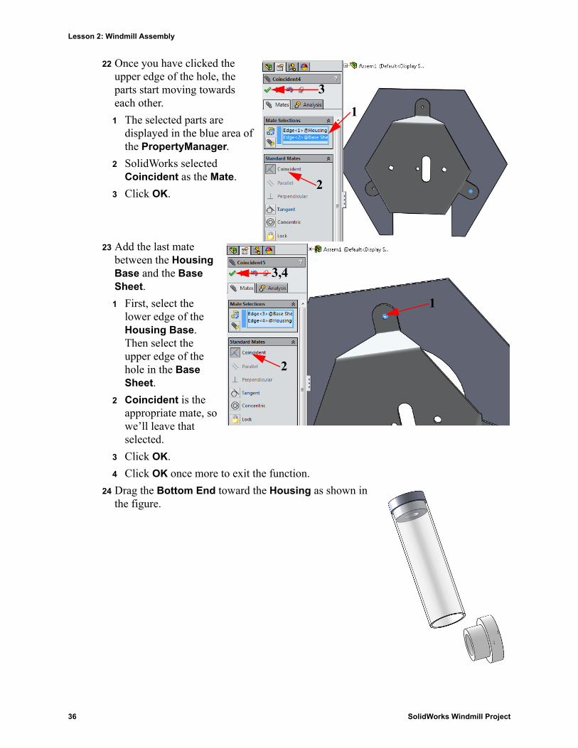
22 Once you have clicked the upper edge of the hole, the parts start moving towards each other.
1 The selected parts are displayed in the blue area of the PropertyManager.
2 SolidWorks selected Coincident as the Mate.
3 Click OK.
23 Add the last mate between the Housing Base and the Base Sheet.
1 First, select the lower edge of the Housing Base. Then select the upper edge of the hole in the Base Sheet.
2 Coincident is the appropriate mate, so we’ll leave that selected.
3 Click OK.
4 Click OK once more to exit the function.
24 Drag the Bottom End toward the Housing as shown in the figure.
1
2
3
1
2
3,4
36 SolidWorks Windmill Project
Lesson 2: Windmill Assembly
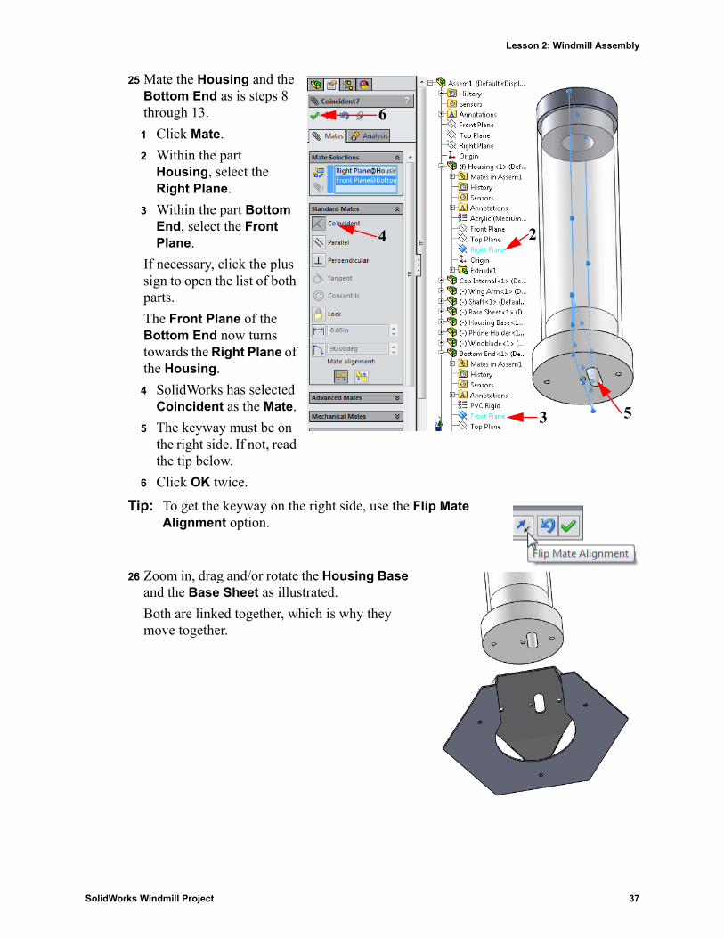
25 Mate the Housing and the Bottom End as is steps 8 through 13.
1 Click Mate.
2 Within the part Housing, select the Right Plane.
3 Within the part Bottom End, select the Front Plane.
If necessary, click the plus sign to open the list of both parts.
The Front Plane of the Bottom End now turns towards the Right Plane of the Housing.
4 SolidWorks has selected Coincident as the Mate.
5 The keyway must be on the right side. If not, read the tip below.
6 Click OK twice.
Tip: To get the keyway on the right side, use the Flip Mate Alignment option.
26 Zoom in, drag and/or rotate the Housing Base and the Base Sheet as illustrated.
Both are linked together, which is why they move together.
2
3
4
5
6
SolidWorks Windmill Project 37
Lesson 2: Windmill Assembly
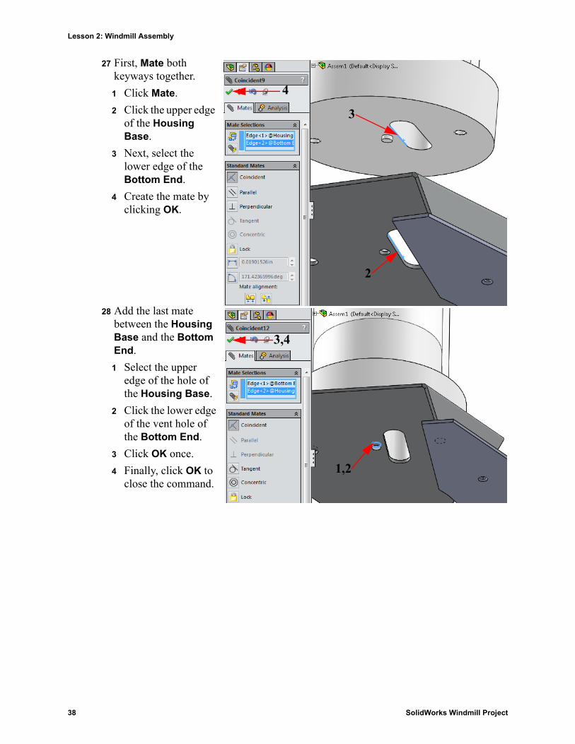
27 First, Mate both keyways together.
1 Click Mate.
2 Click the upper edge of the Housing Base.
3 Next, select the lower edge of the Bottom End.
4 Create the mate by clicking OK.
28 Add the last mate between the Housing Base and the Bottom End.
1 Select the upper edge of the hole of the Housing Base.
2 Click the lower edge of the vent hole of the Bottom End.
3 Click OK once.
4 Finally, click OK to close the command.
2
3
4
1,2
3,4
38 SolidWorks Windmill Project
Lesson 2: Windmill Assembly
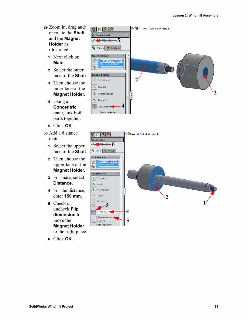
29 Zoom in, drag and/or rotate the Shaft and the Magnet Holder as illustrated.
1 Next click on Mate.
2 Select the outer face of the Shaft.
3 Then choose the inner face of the Magnet Holder.
4 Using a Concentric mate, link both parts together.
5 Click OK.
30 Add a distance mate.
1 Select the upper face of the Shaft.
2 Then choose the upper face of the Magnet Holder.
3 For mate, select Distance.
4 For the distance, enter 150 mm.
5 Check or uncheck Flip dimension to move the Magnet Holder to the right place.
6 Click OK.
2
3
4
5
12
345
6
SolidWorks Windmill Project 39
Lesson 2: Windmill Assembly
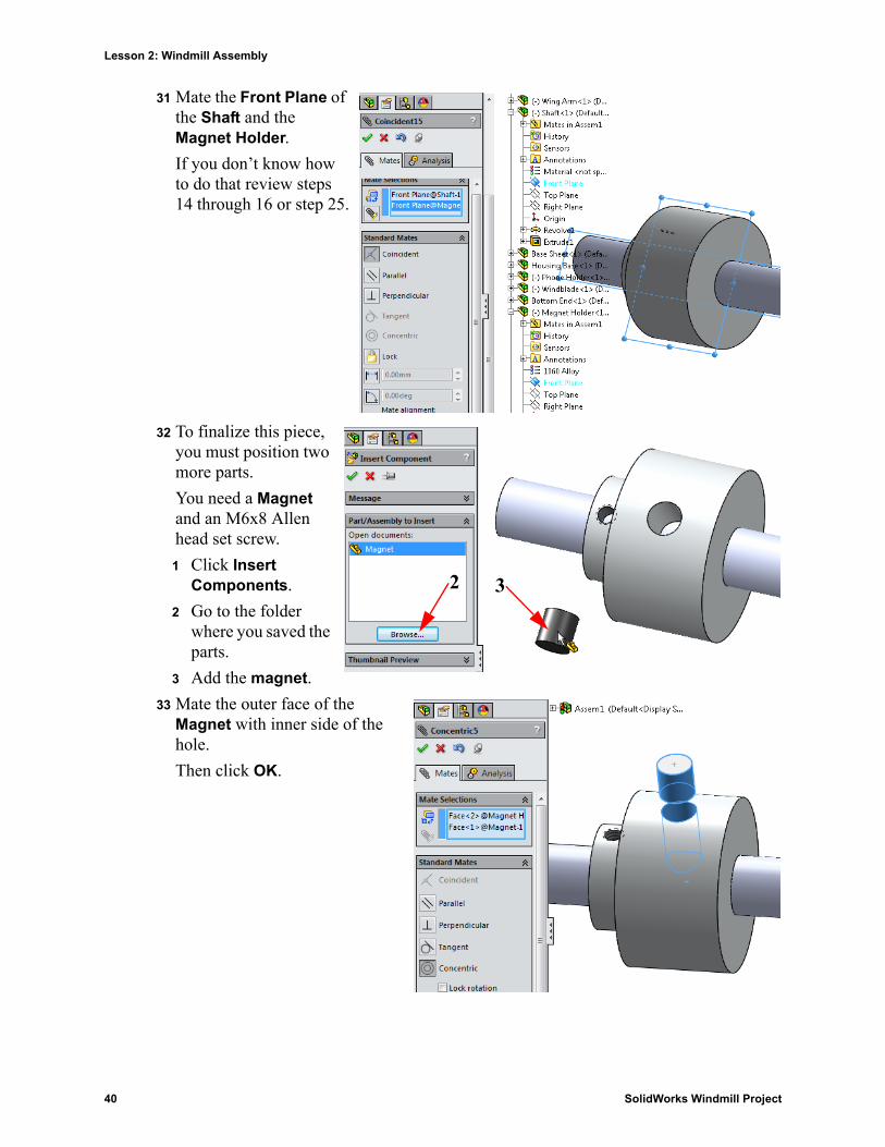
31 Mate the Front Plane of the Shaft and the Magnet Holder.
If you don’t know how to do that review steps 14 through 16 or step 25.
32 To finalize this piece, you must position two more parts.
You need a Magnet and an M6x8 Allen head set screw.
1 Click Insert Components.
2 Go to the folder where you saved the parts.
3 Add the magnet.
33 Mate the outer face of the Magnet with inner side of the hole.
Then click OK.
2 3
40 SolidWorks Windmill Project
Lesson 2: Windmill Assembly
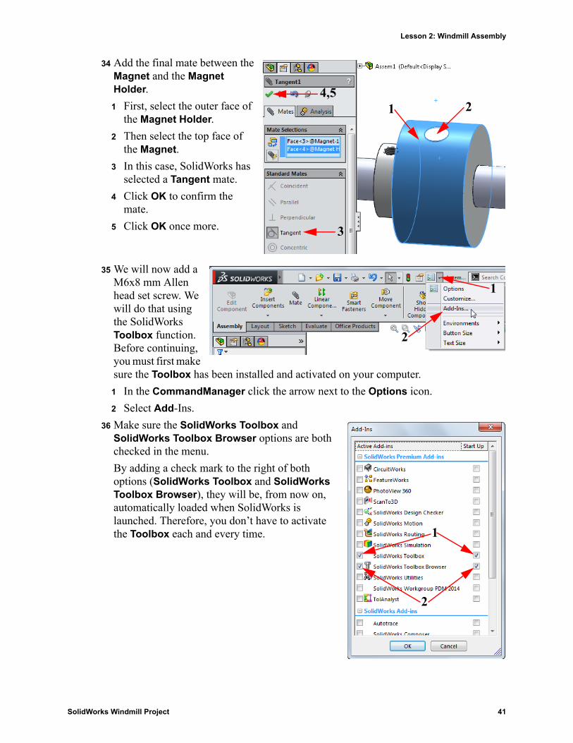
34 Add the final mate between the Magnet and the Magnet Holder.
1 First, select the outer face of the Magnet Holder.
2 Then select the top face of the Magnet.
3 In this case, SolidWorks has selected a Tangent mate.
4 Click OK to confirm the mate.
5 Click OK once more.
35 We will now add a M6x8 mm Allen head set screw. We will do that using the SolidWorks Toolbox function. Before continuing, you must first make sure the Toolbox has been installed and activated on your computer.
1 In the CommandManager click the arrow next to the Options icon.
2 Select Add-Ins.
36 Make sure the SolidWorks Toolbox and SolidWorks Toolbox Browser options are both checked in the menu.
By adding a check mark to the right of both options (SolidWorks Toolbox and SolidWorks Toolbox Browser), they will be, from now on, automatically loaded when SolidWorks is launched. Therefore, you don’t have to activate the Toolbox each and every time.
1 2
3
4,5
1
2
2
1
SolidWorks Windmill Project 41
Lesson 2: Windmill Assembly
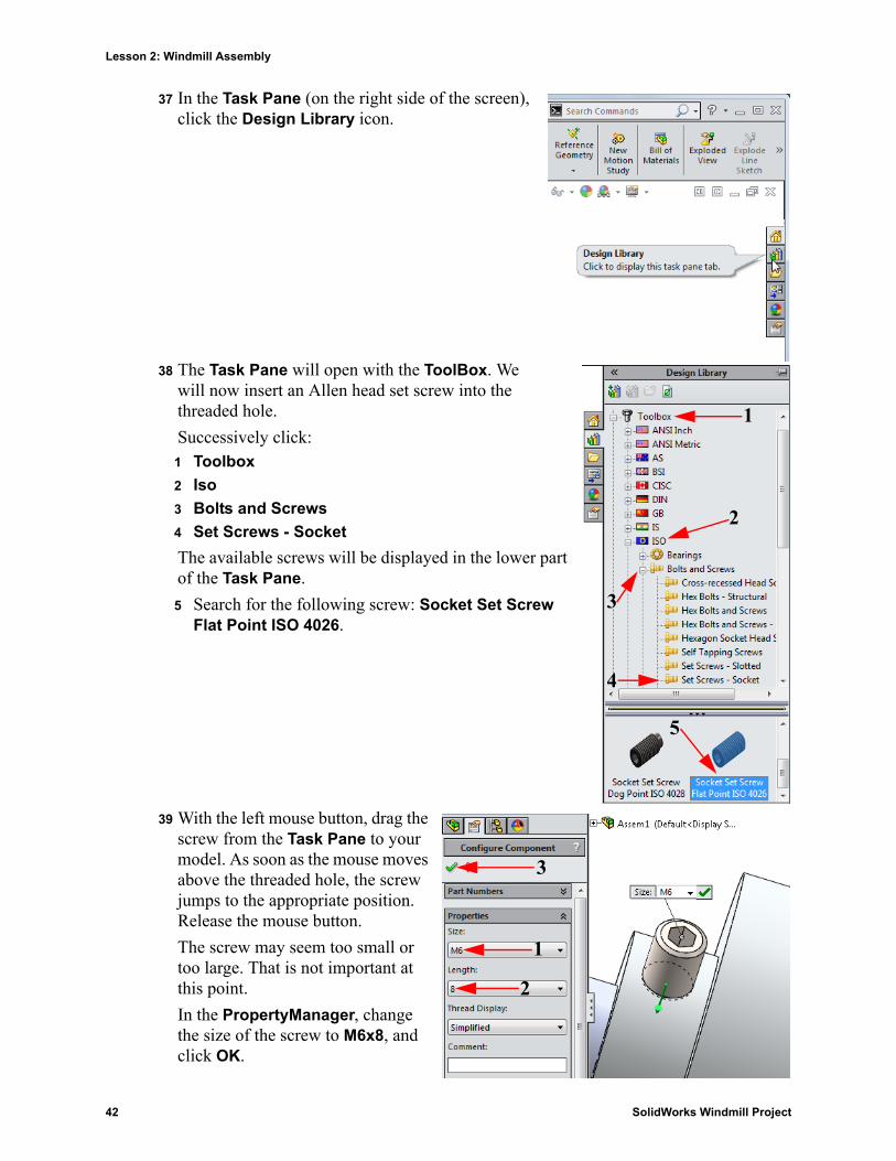
37 In the Task Pane (on the right side of the screen), click the Design Library icon.
38 The Task Pane will open with the ToolBox. We will now insert an Allen head set screw into the threaded hole.
Successively click:1 Toolbox
2 Iso
3 Bolts and Screws
4 Set Screws - Socket
The available screws will be displayed in the lower part of the Task Pane.
5 Search for the following screw: Socket Set Screw Flat Point ISO 4026.
39 With the left mouse button, drag the screw from the Task Pane to your model. As soon as the mouse moves above the threaded hole, the screw jumps to the appropriate position. Release the mouse button.
The screw may seem too small or too large. That is not important at this point.
In the PropertyManager, change the size of the screw to M6x8, and click OK.
1
2
3
4
5
2
1
3
42 SolidWorks Windmill Project
Lesson 2: Windmill Assembly
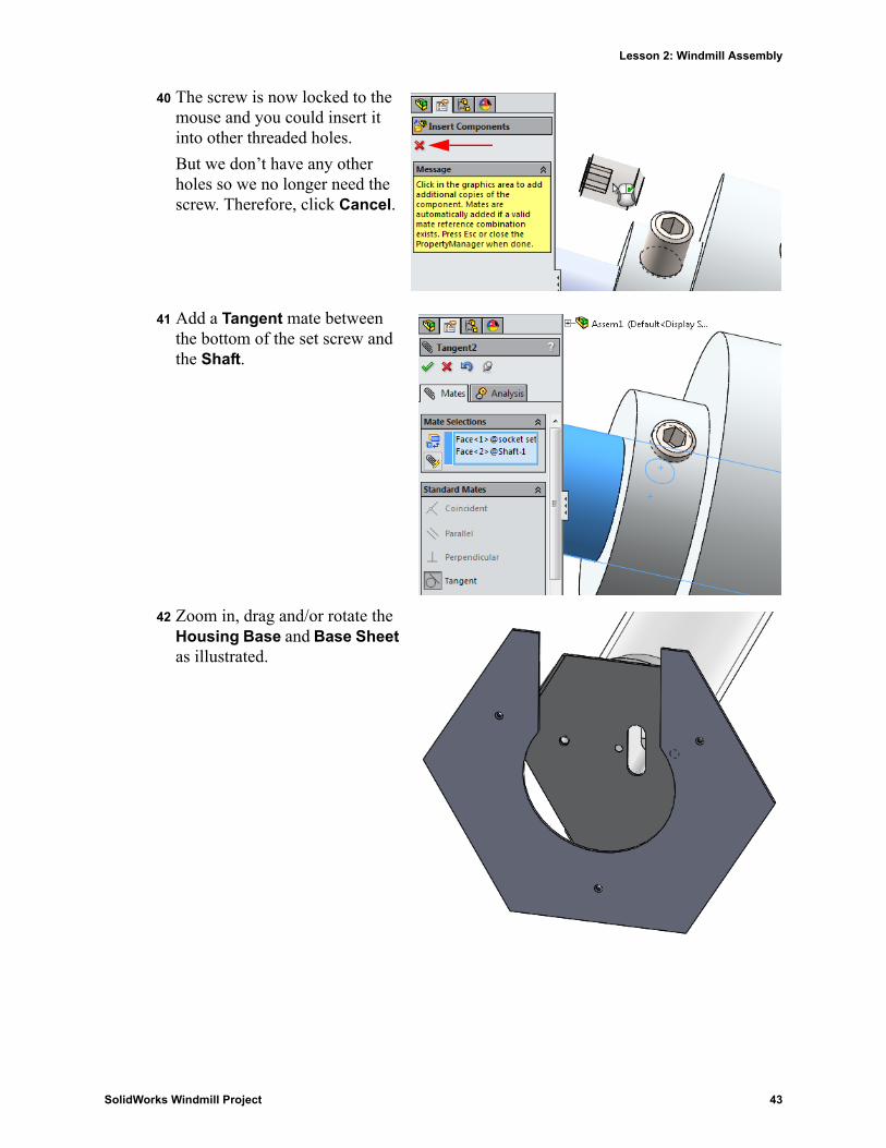
40 The screw is now locked to the mouse and you could insert it into other threaded holes.
But we don’t have any other holes so we no longer need the screw. Therefore, click Cancel.
41 Add a Tangent mate between the bottom of the set screw and the Shaft.
42 Zoom in, drag and/or rotate the Housing Base and Base Sheet as illustrated.
SolidWorks Windmill Project 43
Lesson 2: Windmill Assembly
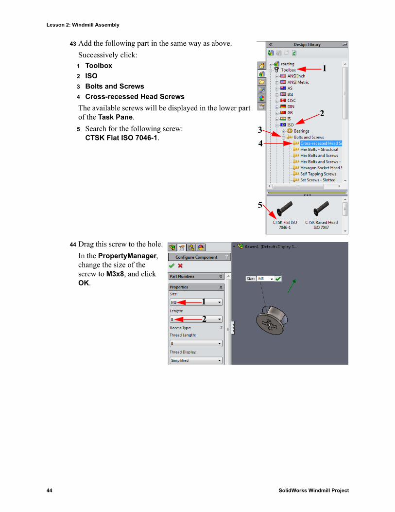
43 Add the following part in the same way as above.
Successively click:1 Toolbox
2 ISO
3 Bolts and Screws
4 Cross-recessed Head Screws
The available screws will be displayed in the lower part of the Task Pane.
5 Search for the following screw:CTSK Flat ISO 7046-1.
44 Drag this screw to the hole.
In the PropertyManager, change the size of the screw to M3x8, and click OK.
1
2
34
5
2
1
44 SolidWorks Windmill Project
Lesson 2: Windmill Assembly
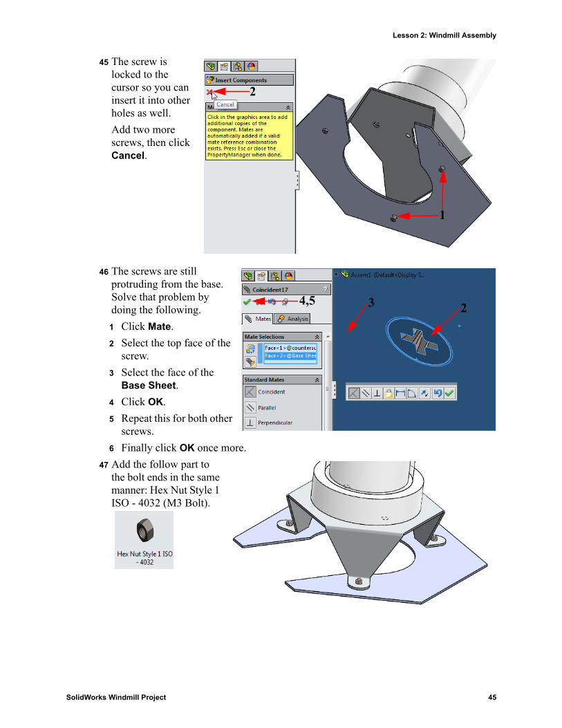
45 The screw is locked to the cursor so you can insert it into other holes as well.
Add two more screws, then click Cancel.
46 The screws are still protruding from the base. Solve that problem by doing the following.
1 Click Mate.
2 Select the top face of the screw.
3 Select the face of the Base Sheet.
4 Click OK.
5 Repeat this for both other screws.
6 Finally click OK once more.
47 Add the follow part to the bolt ends in the same manner: Hex Nut Style 1 ISO - 4032 (M3 Bolt).
1
2
234,5
SolidWorks Windmill Project 45
Lesson 2: Windmill Assembly
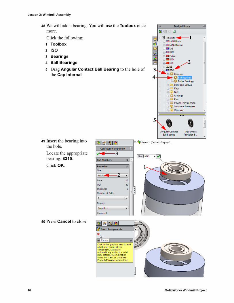
48 We will add a bearing. You will use the Toolbox once more.
Click the following:1 Toolbox
2 ISO
3 Bearings
4 Ball Bearings
5 Drag Angular Contact Ball Bearing to the hole of the Cap Internal.
49 Insert the bearing into the hole.
Locate the appropriate bearing: 8315.
Click OK.
50 Press Cancel to close.
1
234
5
12
3
46 SolidWorks Windmill Project
Lesson 2: Windmill Assembly
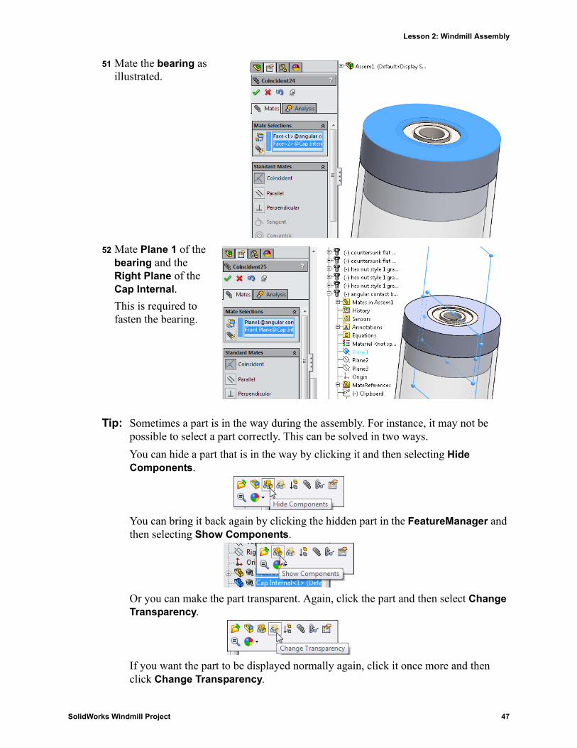
51 Mate the bearing as illustrated.
52 Mate Plane 1 of the bearing and the Right Plane of the Cap Internal.
This is required to fasten the bearing.
Tip: Sometimes a part is in the way during the assembly. For instance, it may not be possible to select a part correctly. This can be solved in two ways.
You can hide a part that is in the way by clicking it and then selecting Hide Components.
You can bring it back again by clicking the hidden part in the FeatureManager and then selecting Show Components.
Or you can make the part transparent. Again, click the part and then select Change Transparency.
If you want the part to be displayed normally again, click it once more and then click Change Transparency.
SolidWorks Windmill Project 47
Lesson 2: Windmill Assembly
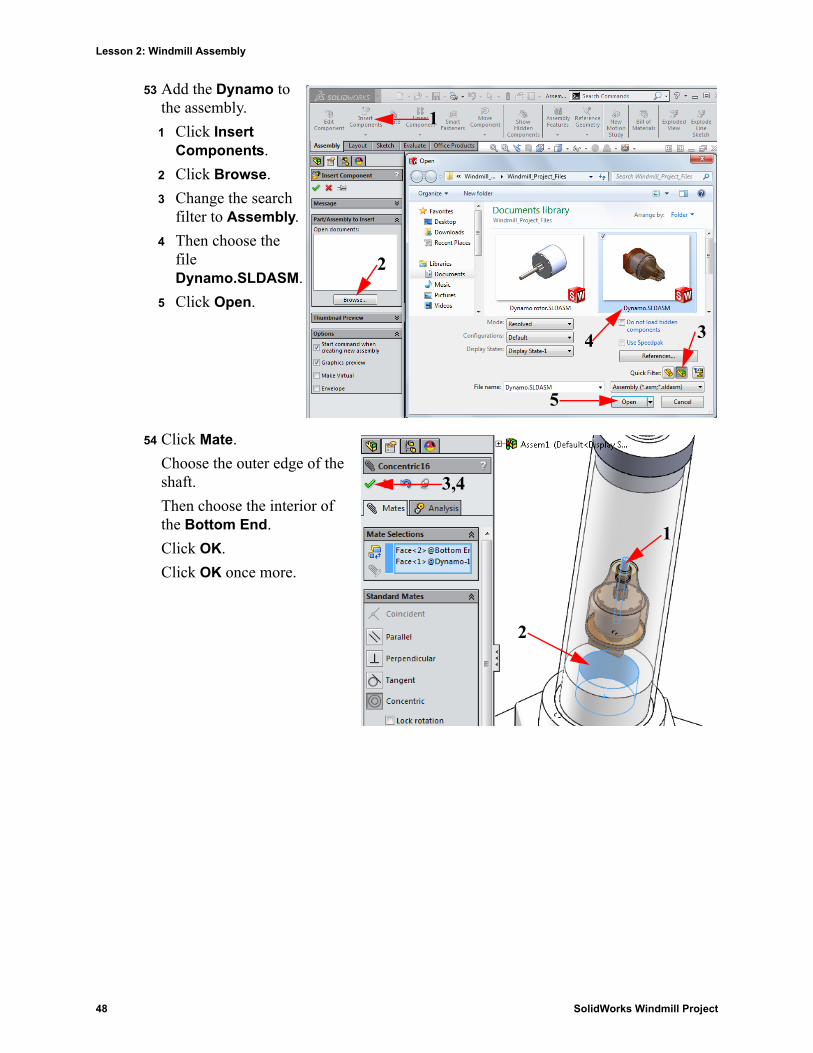
53 Add the Dynamo to the assembly.
1 Click Insert Components.
2 Click Browse.
3 Change the search filter to Assembly.
4 Then choose the file Dynamo.SLDASM.
5 Click Open.
54 Click Mate.
Choose the outer edge of the shaft.
Then choose the interior of the Bottom End.
Click OK.
Click OK once more.
1
2
34
5
1
2
3,4
48 SolidWorks Windmill Project
Lesson 2: Windmill Assembly
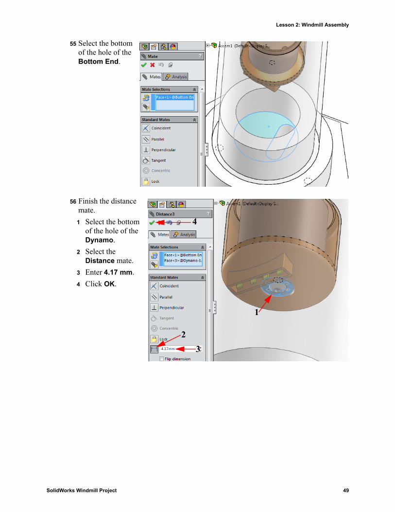
55 Select the bottom of the hole of the Bottom End.
56 Finish the distance mate.
1 Select the bottom of the hole of the Dynamo.
2 Select the Distance mate.
3 Enter 4.17 mm.
4 Click OK.
1
23
4
SolidWorks Windmill Project 49
Lesson 2: Windmill Assembly
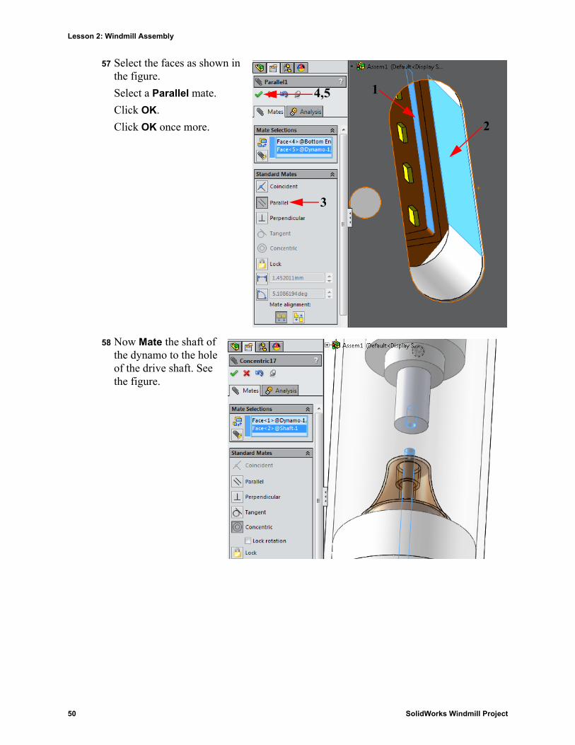
57 Select the faces as shown in the figure.
Select a Parallel mate.
Click OK.
Click OK once more.
58 Now Mate the shaft of the dynamo to the hole of the drive shaft. See the figure.
1
2
3
4,5
50 SolidWorks Windmill Project
Lesson 2: Windmill Assembly
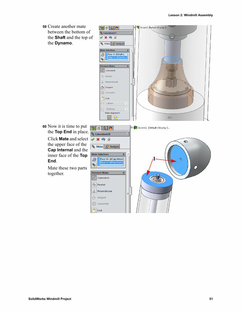
59 Create another mate between the bottom of the Shaft and the top of the Dynamo.
60 Now it is time to put the Top End in place.
Click Mate and select the upper face of the Cap Internal and the inner face of the Top End.
Mate these two parts together.
1
SolidWorks Windmill Project 51
Lesson 2: Windmill Assembly
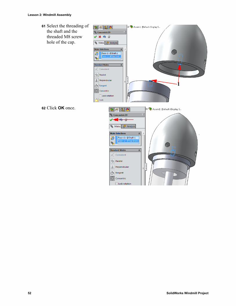
61 Select the threading of the shaft and the threaded M8 screw hole of the cap.
62 Click OK once.
1
52 SolidWorks Windmill Project
Lesson 2: Windmill Assembly
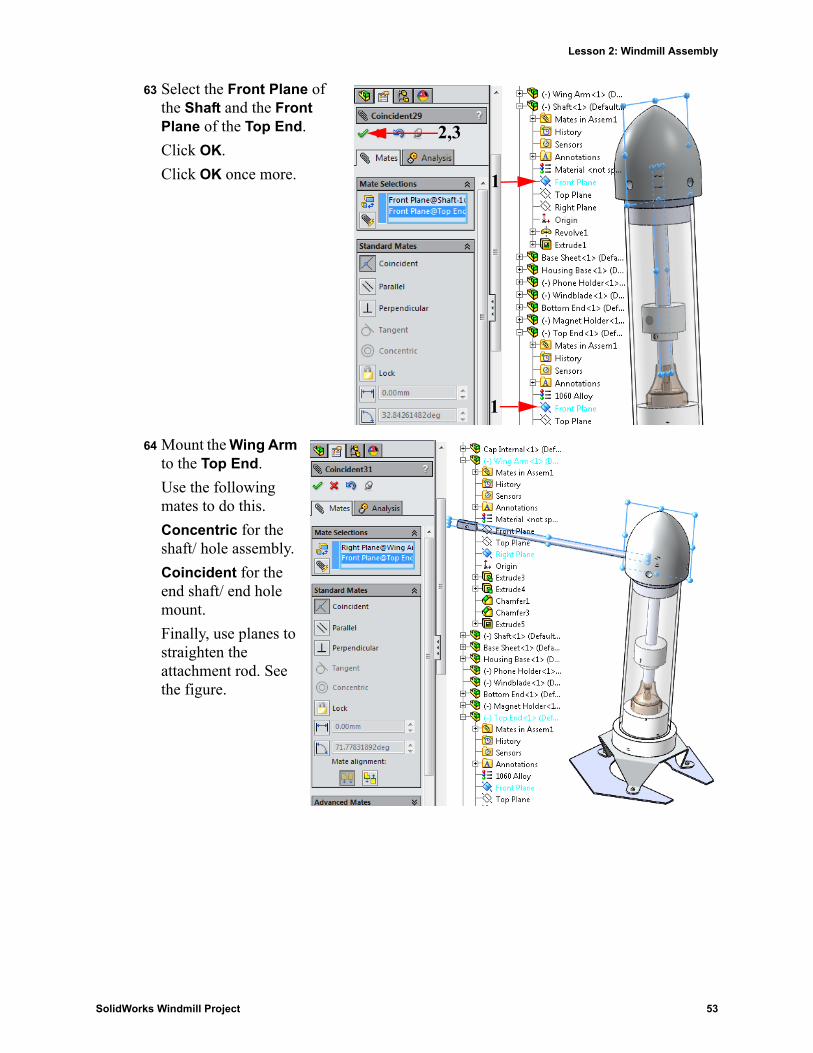
63 Select the Front Plane of the Shaft and the Front Plane of the Top End.
Click OK.
Click OK once more.
64 Mount the Wing Arm to the Top End.
Use the following mates to do this.
Concentric for the shaft/ hole assembly.
Coincident for the end shaft/ end hole mount.
Finally, use planes to straighten the attachment rod. See the figure.
1
1
2,3
SolidWorks Windmill Project 53
Lesson 2: Windmill Assembly
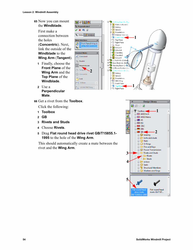
65 Now you can mount the Windblade.
First make a connection between the holes (Concentric). Next, link the outside of the Windblade to the Wing Arm (Tangent).
1 Finally, choose the Front Plane of the Wing Arm and the Top Plane of the Windblade.
2 Use a Perpendicular Mate.
66 Get a rivet from the Toolbox.
Click the following:1 Toolbox
2 GB
3 Rivets and Studs
4 Choose Rivets.
5 Drag Flat round head drive rivet GB/T15855.1-1995 to the hole of the Wing Arm.
This should automatically create a mate between the rivet and the Wing Arm.
1
1
2
1
2
3
4
5
54 SolidWorks Windmill Project
Lesson 2: Windmill Assembly
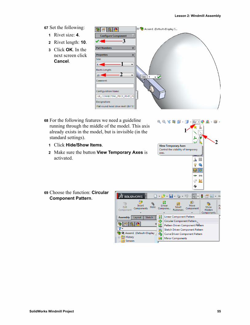
67 Set the following:
1 Rivet size: 4.
2 Rivet length: 10.
3 Click OK. In the next screen click Cancel.
68 For the following features we need a guideline running through the middle of the model. This axis already exists in the model, but is invisible (in the standard settings).
1 Click Hide/Show Items.
2 Make sure the button View Temporary Axes is activated.
69 Choose the function: Circular Component Pattern.
1
2
3
1
2
SolidWorks Windmill Project 55
Lesson 2: Windmill Assembly
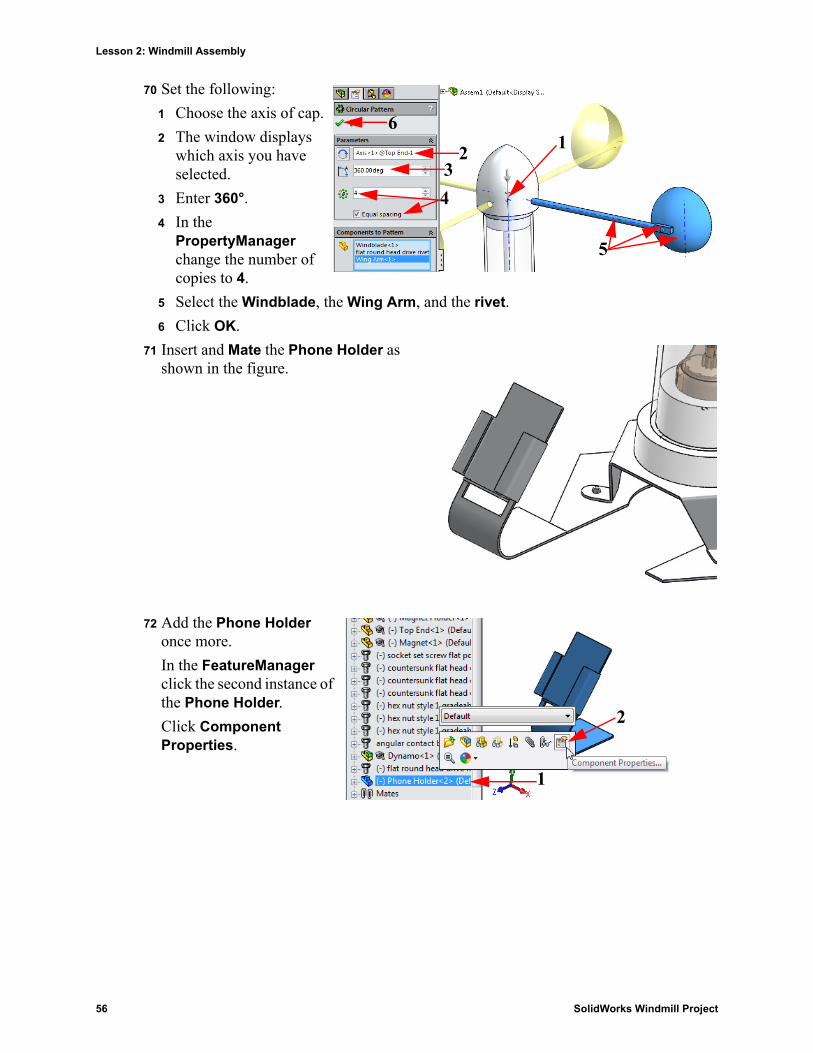
70 Set the following:
1 Choose the axis of cap.
2 The window displays which axis you have selected.
3 Enter 360°.
4 In the PropertyManager change the number of copies to 4.
5 Select the Windblade, the Wing Arm, and the rivet.
6 Click OK.
71 Insert and Mate the Phone Holder as shown in the figure.
72 Add the Phone Holder once more.
In the FeatureManager click the second instance of the Phone Holder.
Click Component Properties.
1234
5
6
1
2
56 SolidWorks Windmill Project
Lesson 2: Windmill Assembly
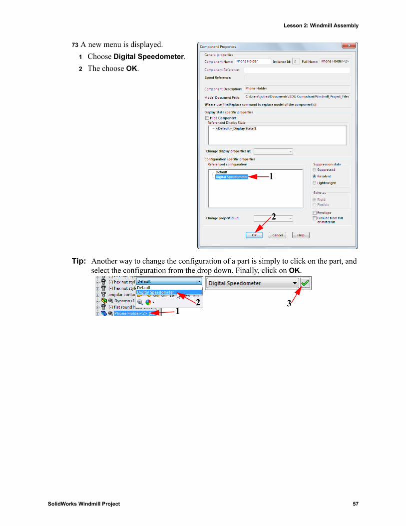
73 A new menu is displayed.
1 Choose Digital Speedometer.
2 The choose OK.
Tip: Another way to change the configuration of a part is simply to click on the part, and select the configuration from the drop down. Finally, click on OK.
1
2
132
SolidWorks Windmill Project 57
Lesson 2: Windmill Assembly
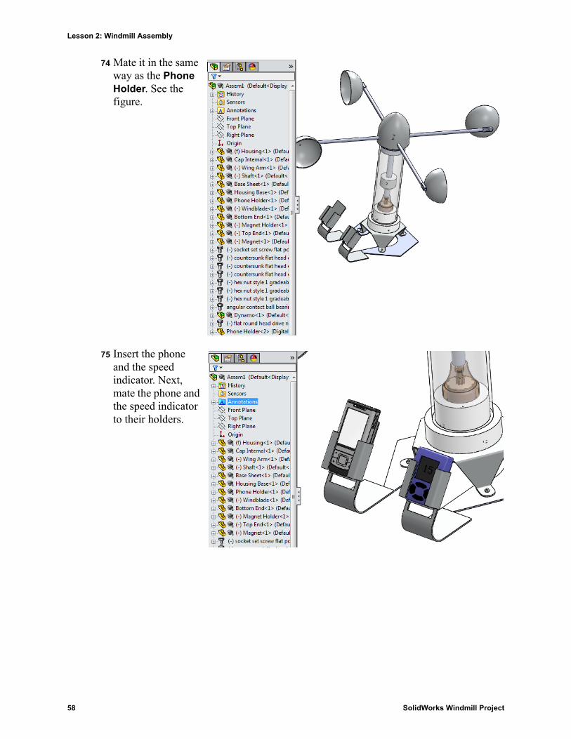
74 Mate it in the same way as the Phone Holder. See the figure.
75 Insert the phone and the speed indicator. Next, mate the phone and the speed indicator to their holders.
58 SolidWorks Windmill Project
Lesson 2: Windmill Assembly
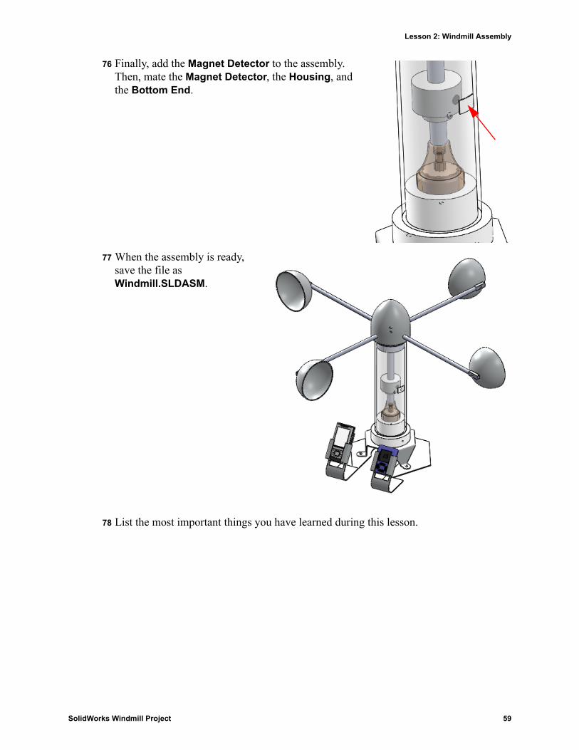
76 Finally, add the Magnet Detector to the assembly. Then, mate the Magnet Detector, the Housing, and the Bottom End.
77 When the assembly is ready, save the file as Windmill.SLDASM.
78 List the most important things you have learned during this lesson.
SolidWorks Windmill Project 59

Lesson 2: Windmill Assembly
60 SolidWorks Windmill Project