Solid_Modeling_Project_Reverse engineering of a computer mouse and documentation of its solid model
23
City College of New York School of Engineering Mechanical Engineering Department Spring-2014 Mechanical Engineering I 6500: Computer-Aided Design Instructor : Prof. Gary Benenson Student : Mehmet Bariskan Solid Modeling Project #1 : Reverse engineering of a computer mouse and documentation of its solid model
-
Upload
mehmet-bariskan -
Category
Documents
-
view
101 -
download
1
Transcript of Solid_Modeling_Project_Reverse engineering of a computer mouse and documentation of its solid model

City College of New York School of Engineering
Mechanical Engineering Department
Spring-2014
Mechanical Engineering I 6500: Computer-Aided Design Instructor : Prof. Gary Benenson
Student : Mehmet Bariskan
Solid Modeling Project #1 : Reverse engineering of a
computer mouse and documentation of its solid model

2
Reverse Engineering
Engineering is the profession involved in designing, manufacturing, constructing and maintaining of
products, systems, and structures. We may say that there are two types of engineering: forward
engineering and reverse engineering.
Reverse engineering enables the duplication of an existing part by capturing the component's physical
dimensions, features, and material properties, without the aid of drawings, documentation or computer
model.
Reverse engineering is very common is such diverse fields as automotive, consumer products,
electronics, and mechanical design. Following are some reason for reverse engineering a part or
product:
1. The original manufacturer of a product no longer produces a product
2. There is inadequate documentation of the original design
3. The original manufacturer no longer exists, but a customer needs the product
4. The original design documentation has been lost or never existed
5. To analyze the good and bad features of a competitors' product
6. To gain competitive benchmarking methods to understand competitor's products and develop
better products
7. The original equipment manufacturers are either unwilling or unable to supply replacement
parts, or demand inflated costs for sole-source parts
Overview
I am going to use the reverse engineering method to reconstruct a 3-D model of a computer
mouse’s shell. The computer mouse is shown in Figure 1.
Figure 1: A Computer Mouse by Logitech M325

3
The mouse’s outer shell and most of its internal mechanical parts, including the wheel are made of
acrylonitrile butadiene styrene (ABS) plastic that is injection-molded. The wheel is coated with rubber.
The reverse-engineering process needs hardware and software that work together. The hardware is
used to measure an object, and the software reconstructs it as a 3-D model. The physical object can be
measured using 3-D scanning technologies like a coordinate measuring machine, laser scanner,
structured light digitizer or computed tomography. The physical object also can be measured using a
variety of hand measurement tools such as calipers and gages.
In this project, I will do a manual measurement on the computer mouse. Hand tools such as a caliper, a
radius & fillet gage, a ruler and wire are used to capture the most of the dimensions. Hand tools are
shown below in Figure 2.
Figure 2: Hand Tools
4
The linear distances are measured by using either the ruler or caliper. The wire was used to get the
curved shapes from the computer mouse to a drawing paper. An example of preparing a wire template
is shown in Figure 3. My freehand drawing is shown in Figure 4. (A larger scale figure is attached into the
Drawing Section which is shown in Figure 32.)
Figure 3: Preparing a Wire Template
Figure 4: Freehand Drawing

5
SolidWorks software has been used to design the computer mouse by using the aid of my hand
sketches. The “Grid” option is used to get better results in SolidWorks. I have changed the grid spacing
to 5 mm in the SolidWorks option menu to catch same grid distance with my freehand drawing.
CREATING SURFACES
I have attached my front and top view sketch picture into SolidWorks top and its front plane by using
“Sketch Picture” command which is shown in Figure 5.
Figure 5: Placing the Front and Top View in SolidWorks
I have started from the bottom housing section. The “Project Curve” command was used to create the
top guide curve after creating the projection sketches by following the freehand drawing which is shown
in Figure 6.
Figure 6: Creating the Top Guide Curve

6
Secondly, I have used the “Surface Loft” command to create the bottom housing section of the
computer mouse. Selected profiles and guide curves are shown in Figure 7. Bottom guide curve is
created with “Project Curve” command by choosing the projection sketches.
Figure 7: Creating Bottom Housing Section
I have used the “Surface Loft” command to create the middle housing section of the computer mouse.
Selected profiles and guide curves are shown in Figure 8.
Figure 8: Creating the Middle Housing Section

7
I have used the “Fillet Surface” command to create the top housing section of the computer mouse. The
constraint curve was created by following the hand sketch projection and the top edge of the middle
housing section is chosen as a patch boundary. They are shown in Figure 9.
Figure 9: Creating the Top Housing Section
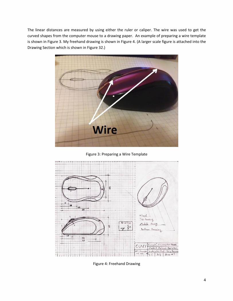
The next step that I will focus on the top and bottom surfaces on the computer mouse.
The front section of the top face has a deformed shape. I have created control curves and control points
by using the “Freeform” command. I have pushed and pulled the created points through the vertical axis
according to the physical object. The most accurate shape of the front section of the computer mouse is
shown in Figure 10. The “Surface Offset” command has been used to create a top surface of the middle
housing which is shown in Figure 11.
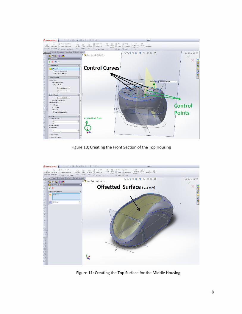
The “Lofted Surface” command was used to create a surface between the top of the middle housing and
the top of the top housing which is shown in Figure 12.
The bottom surface of the mouse was created by using the “Fillet Surface” command. The edge of the
bottom housing was used as a patch boundary which is shown in Figure 13.
I have created a composite curve for the back section of the bottom housing, which is shown in Figure
14.
8
Figure 10: Creating the Front Section of the Top Housing
Figure 11: Creating the Top Surface for the Middle Housing
9
Figure 12: Creating the Lofted Surface
Figure 13: Creating the Bottom Face

10
Figure 14: Creating the Composite Curve
After the external surfaces are completed, it’s time to create the body parts.
PARTS
1- TOP HOUSING
I have created a new part by using the “Insert into New Part” command. After new part has been
created, I have attached the top view of the freehand drawing which is shown in Figure 15.
Figure 15: Creating the Top Housing Part-1
11
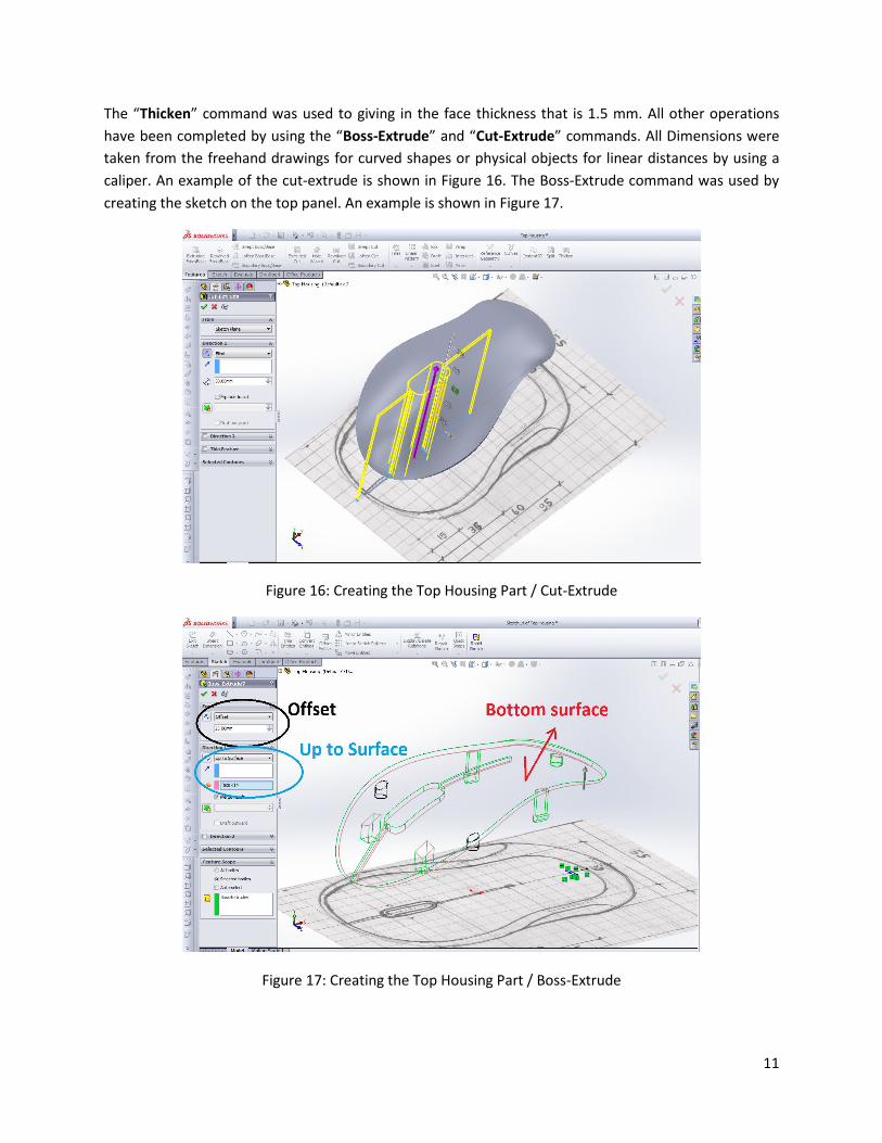
The “Thicken” command was used to giving in the face thickness that is 1.5 mm. All other operations
have been completed by using the “Boss-Extrude” and “Cut-Extrude” commands. All Dimensions were
taken from the freehand drawings for curved shapes or physical objects for linear distances by using a
caliper. An example of the cut-extrude is shown in Figure 16. The Boss-Extrude command was used by
creating the sketch on the top panel. An example is shown in Figure 17.
Figure 16: Creating the Top Housing Part / Cut-Extrude
Figure 17: Creating the Top Housing Part / Boss-Extrude

12
2- MIDDLE HOUSING
The “Knit Surface” command was used before exporting the surface. The surfaces that I have knitted are
shown in Figure 18.
Figure 18: Creating the Knitted Surfaces
After then, I have created a new part by using the “Insert into New Part” command. The thickness of the
surface is 1.5 mm. The middle housing part is shown in Figure 18.
Figure 18: Creating the Middle Housing Part

13
I have attached a picture into SolidWorks that was taken from the physical object. I have followed the
edges to create lines for cutting and extruding surfaces which are shown in Figure 19.
Figure 19: Creating the Edge Lines from the Picture in SolidWorks
3- BOTTOM HOUSING
The “Knit Surface” command was used before inserting the part. The surfaces that we have knitted are
shown in Figure 20.
Figure 20: Creating the Bottom Housing Part

14
I have started with the back section of the bottom housing part. The “Surface-Extrude” command was
used to close the section which is shown in Figure 21.
Figure 21: Creating the Bottom Housing Part / Surface Extrude
The “Surface-Trim” command was used to trim the unwanted surfaces which are shown in Figure 22.
Figure 22: Creating the Bottom Housing Part / Trimmed Surface

15
The “Fill Surface” command was used to create a surface which is shown in Figure 23.
Figure 23: Creating the Bottom Housing Part / Fill Surface
The “Knit Surface and Shell” commands were used to give a thickness to the faces. First, Knit Surface
command was used with “Try to form solid” option and up of the part surface was chosen while creating
the shell with 2 mm thickness. The part is shown in Figure 24.
Figure 24: Creating the Bottom Housing Part / Knit Surface

16
After the shell operation, I have used the cut-extrude and boss-extrude commands to create the bottom
holes and the battery housing section which is shown in Figure 25.
Figure 25: Creating the Bottom Housing Part / Knit Surface
4- SCROLL WHEEL
The wheel has two parts. We may call them as an inner wheel and a scroll wheel which are shown in
Figure 26. A detailed drawing will be added into the drawing section.
Figure 26: Inner and Outer Wheels

17
RESULTS
I have tried to design a computer mouse model by using hand sketches in this project. In this project, my
aim was to model of the computer mouse accurately as possible. After solid modeling, I have created
the final computer-generated drawings. All the SolidWorks drawings and the assembly views are shown
in Figures from 27 to 31.
DISCUSSION
In this project, I have learned that the procedure of the reverse engineering method. The procedure that
I follow;
1- Measure the real object
2- Prepare a template for the shapes where I cannot measure
3- Prepare a freehand drawing
4- Design in SolidWorks.
5- Create the engineering drawings
First and most important problem that I faced during this project was the measurement. I have spent
most of the project time while trying to get the accurate measurement. The final solid model that I have
created still is not same dimensions with the real object after all effort that I have made. It shows me
that, I need to learn the manual measurement techniques for the complex parts. But, I think there is no
way to get the entire measurement %100 accurate.
This was an important learning experience which truly took a lot of time to investigate. It will give me a
lot of motivation to design more complicated objects in the future.

18
DRAWINGS
Figure 27: Top Housing

19
Figure 28: Middle Housing

20
Figure 29: Bottom Housing

21
Figure 30: Wheel
22
ASSEMBLY
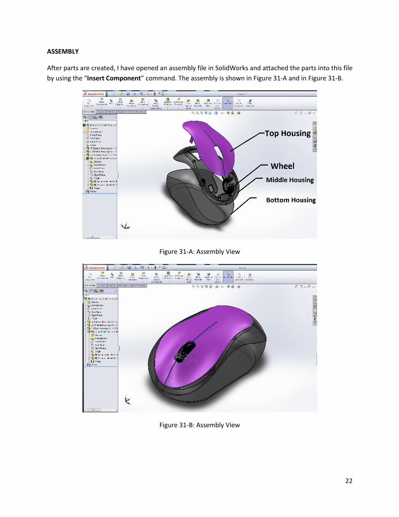
After parts are created, I have opened an assembly file in SolidWorks and attached the parts into this file
by using the “Insert Component” command. The assembly is shown in Figure 31-A and in Figure 31-B.
Figure 31-A: Assembly View
Figure 31-B: Assembly View

23
Figure 32: Freehand Drawing