Solidification Front Tilt Angle Effect on Potential ...SOLIDIFICATION FRONT TILT ANGLE EFFECT ON...
16
SOLIDIFICATION FRONT TILT ANGLE EFFECT ON POTENTIAL NUCLEATION SITES FOR FRECKLING IN THE REMELT OF NI-BASE SUPERALLOYS Jairo Valdes 1, 2 , Xingbo Liu 1 , Paul King 3 , Christopher Cowen 3 , Paul Jablonski 3 1 Mechanical & Aerospace Engineering Department, West Virginia University, Morgantown, WV 26506-6106, USA 2 Escuela de Ingeniería Mecánica, Universidad del Valle, Cali, COLOMBIA 3 National Energy Technology Laboratory, Albany, OR 97321, USA Keywords: Tilt angle, Freckle, Ra Number, Permeability ABSTRACT By considering the mushy layer as a porous media with variable permeability, a Rayleigh number based freckling criterion was developed from the Flemings ratio between the magnitude of the interdendritic flow velocity and the solidification rate. The proposed form includes the effect of the tilt angle by preserving the anisotropic nature of the permeability tensor throughout the derivation and uses Poirier’s experimentally determined functional forms for the parallel and perpendicular components. The proposed form of Rayleigh number criterion was found to provide better resolution when evaluated against available experimental data in the literature. Especially, it showed that the nucleation of channels in the mushy layer leading to freckles is equally probable in the proximity of the tips of the dendrites or deeper in the mushy layer, for example at approximately 0.7 liquid fraction and 0.4 liquid fraction respectively, depending on the angle of tilt of the solidification front. Introduction Large Ni-base superalloy ingots required for increased efficiency gas turbines in power applications have a marked tendency to form macrosegregation defects as freckles. These defects are discontinuities in the material that act as stress concentration points making it highly sensitive to fatigue crack growth under thermal and mechanical cyclic loads. They cannot be removed by thermo-mechanical treatment making the ingot unsuitable and should be scrapped. Advances in quality assurance of electrodes and improved control of the VAR process have contributed to reduce the incidence of freckles in large ingots 1 but freckles are still found when the VAR stability is perturbed by transients in the arc melting conditions that affect the macroscopic transfer of mass heat and momentum. 2 It is necessary to continue efforts for better 79
Transcript of Solidification Front Tilt Angle Effect on Potential ...SOLIDIFICATION FRONT TILT ANGLE EFFECT ON...
SOLIDIFICATION FRONT TILT ANGLE EFFECT ON POTENTIAL
NUCLEATION SITES FOR FRECKLING IN THE REMELT OF NI-BASE
SUPERALLOYS
Jairo Valdes1, 2
, Xingbo Liu1, Paul King
3, Christopher Cowen
3, Paul Jablonski
3
1Mechanical & Aerospace Engineering Department, West Virginia University,
Morgantown, WV 26506-6106, USA 2Escuela de Ingeniería Mecánica, Universidad del Valle, Cali, COLOMBIA
3 National Energy Technology Laboratory, Albany, OR 97321, USA
Keywords: Tilt angle, Freckle, Ra Number, Permeability
ABSTRACT
By considering the mushy layer as a porous media with variable permeability, a Rayleigh
number based freckling criterion was developed from the Flemings ratio between the magnitude
of the interdendritic flow velocity and the solidification rate. The proposed form includes the
effect of the tilt angle by preserving the anisotropic nature of the permeability tensor throughout
the derivation and uses Poirier’s experimentally determined functional forms for the parallel and
perpendicular components. The proposed form of Rayleigh number criterion was found to
provide better resolution when evaluated against available experimental data in the literature.
Especially, it showed that the nucleation of channels in the mushy layer leading to freckles is
equally probable in the proximity of the tips of the dendrites or deeper in the mushy layer, for
example at approximately 0.7 liquid fraction and 0.4 liquid fraction respectively, depending on
the angle of tilt of the solidification front.
Introduction
Large Ni-base superalloy ingots required for increased efficiency gas turbines in power
applications have a marked tendency to form macrosegregation defects as freckles. These defects
are discontinuities in the material that act as stress concentration points making it highly
sensitive to fatigue crack growth under thermal and mechanical cyclic loads. They cannot be
removed by thermo-mechanical treatment making the ingot unsuitable and should be scrapped.
Advances in quality assurance of electrodes and improved control of the VAR process have
contributed to reduce the incidence of freckles in large ingots1 but freckles are still found when
the VAR stability is perturbed by transients in the arc melting conditions that affect the
macroscopic transfer of mass heat and momentum. 2 It is necessary to continue efforts for better
79
understanding of the mechanisms of nucleation and growth of freckles during VAR process in
order to expand the processing window and further increase the diameter of ingots to meet the
demands of larger rotor discs for the new generation of gas turbines.
Nucleation sites and freckle formation mechanism
Since near four decades ago the freckle formation problem has been studied by researchers in
different areas of science and engineering, and it has been understood as a case of thermo-solutal
convection in a reactive porous media. 3
Therefore, there is vast collection of publications on the
subject and it is not intended on this work to include a comprehensive literature review, but to
include the most relevant antecedents. Consider the case of an ingot cooled from the bottom with
heat flow assumed unidirectional, and solidification process occurring with constant upward rate.
Once the positive thermal gradient (∂T/∂z) is established and solidification advances,
composition and density gradients develop along the mush layer due to partitioning of solute
elements. According to the set of solute elements and their partition behavior, the resulting
density gradient (∂ρ/∂z) can be positive or negative and this defines the conditions by which
interactions may occur between the interdendritic liquid and the solid dendrites. If the density
gradient is positive, a density inversion condition exists and the buoyancy forces could become
strong enough to overcome the impedance to flow offered by the dendritic array. Upward
transport of interdendritic liquid will occur with a corresponding concomitant flow of heavier
reposition liquid from higher locations. The flow of segregated liquid will remelt the already
formed solid while it attains thermodynamical equilibrium with the new surroundings; and the
columnar regions with decreased solid fraction, and hence decreased resistance to the flow,
eventually turn into chimneys through which plumes of interdendritic liquid are projected into
the bulk liquid. Lastly, the remaining chimneys solidify as the defects known as freckles
containing low melting point-close to eutectic composition material and porosity. This general
mechanism is widely accepted and has been supported by detailed experimental observations and
numerical simulations using both analogous transparent systems and metallic alloys.4, 5
Single
crystal alloys with high content of refractory elements are typically susceptible to freckles
formed by this mechanism, as well as some wrought superalloys.6 Generalized agreement exists
about the convective origin of upward interdendritic liquid flow and its role on formation of
vertical freckles, but there is no complete consonance about the specific nucleation sites and
80
evolution sequence of the channels leading to their formation. Sample and Hellawell7 concluded
that channels originate at the growth front and propagate back into the mush. For the nucleation
to occur, it is deemed necessary the evolution of double diffusive finger convection cells in a thin
liquid layer with inverted density built in top of the mush. Their proposed sequence of nucleation
at the mush low solid fraction region and downward growth of the channels has been later
supported by numerical simulations and experiments.7,
8, 9, 10, 11
A major supporting evidence lies
on the fact that when externally induced shear movement between the bulk liquid and the top
mush layer disrupts the convection cells evolution, freckles are not formed or if they do appear,
their distribution is not random, but are confined to the walls of the ingot, where the relative
movement is weaker. Differently, linear stability analysis of thermosolutal convection performed
by Worster12
on ‘ideal’ mush layers lead to the conclusion that there are two possible modes of
convection which can occur independently. The first mode called boundary layer mode
corresponds to the double diffusive fingers on the interface mush-bulk liquid, which is
understood to leave the fluid in the mush stagnant, while the second convection mode
denominated mush layer mode happens within the mush and causes perturbations in the solid
fraction leading to formation of chimneys.12, 13
This hypothesis of nucleation and growth of
channels inside the mush layer has also been supported by theoretical and experimental results.14,
15, 16 When segregation of the interdendritic liquid builds a negative density gradient in the mush
layer, it will be gravitationally stabilizing and the interdendritic liquid will be stratified with no
density inversion observed. Whenever the heat flux is not aligned with gravity, the solidification
front is not perpendicular to the gravity vector and it has been proposed that the heavier liquid
will tend to seep between the dendrites, following a path almost parallel to the liquidus isotherm
melting-eroding the dendrites on its path and give origin to the freckles seen on VAR ingots.17, 18
This proposed mechanism for VAR freckles has been devised mostly from the observed
morphology and characterization of freckles in solidified ingots. Regarding the nucleation sites
for the formation of channels leading to freckles, Auburtin et al.19
used SEM/EDAX to
determine freckles average composition and compared it with the segregation profiles to
conclude that they formed from a mush region with solid fraction of 0.4 to 0.6. When compared
with the density inversion case, appreciably less detailed information is available regarding the
sequence of events leading to the nucleation and growth of freckles in VAR due to heavier
interdendritic liquid transport. Usually freckles are found in the mid radius and center of VAR
81
ingots, and are more frequently found when the molten metal pool has a steeper ‘bowl shape’
like the one when the melting rate is high or in ESR ingots. Numerical simulations have
corroborated the foundry practice knowledge that abrupt variations on the controlling parameters
of VAR induce perturbations in the temperature and composition of the interdendritic liquid that
have a strong influence on freckle nucleation and growth. 20,
21, 22
Nevertheless, no industrial
application of direct simulation of freckles in VAR has been reached. It has been proposed that
horizontal directional solidification experiments should better resemble the freckling conditions
for VAR ingots. 23,
24
Results showed that freckles can propagate without the influence of the
strong electromagnetic Lorentz forces present on the VAR process, indicating that it is feasible
that freckles have a nucleation mechanism that not necessarily depends on the bulk liquid
convection. A complete understanding of the nucleation and growth of freckles in VAR ingots is
required in order to construct accurate predictions and more efficient prevention strategies.
Prediction of freckles formation
Two major methodology tendencies could be recognized on the prediction of freckle formation:
mathematically derived criterions and predictions based on numerical solution of the continuity
equations. 25
The first criterions developed were based on functional forms involving controlling
operational parameters that could be measured or established in industrial practice like the
gradient, melting rate or the local solidification time.3 M. C. Flemings and G.E. Nereo
26 derived
a mathematical description of macrosegregation and postulated the local solute redistribution
equation, which constituted the foundation for the Flemings criterion presented as the inequality
1. Basically, a freckle channel will grow if the liquid flow from colder to hotter regions is faster
that the rate at which crystals grow.27
1v T
ε⋅∇
≤ −r [1]
Flemings et al. proposed criterion presents a physical explanation of the remelting effect of the
established convective flow, but requires relating the interdendritic flow with its causes. That is
why their expression have been considered as determining if a channel will evolve rather than
predicting its nucleation.10,
15
Currently, the most accepted freckling criterion is the one based on
the maximum Rayleigh number concept. The Rayleigh number may be defined as the ratio
between the buoyancy and the viscous dissipation forces at a point of interest. In the particular
82
case of convection in the mushy zone, the driving force is due to compositional buoyancy and
the viscous dissipation is related to flow impedance through the dendritic array. The Rayleigh
number based criterion has the advantage that incorporates the thermal and compositional effects
over the freckling tendency. The threshold value of the Rayleigh number defining between the
freckling and non freckling conditions is denominated critical Rayleigh number, and it is
theoretically believed to be universally applicable. If the maximum Rayleigh number for a
determined set of conditions is below the critical value, freckles are not expected to form, but it
is possible that the system could have a maximum Rayleigh number higher than the critical value
and yet no freckles being formed.28
The Rayleigh number follows from the dimensionless
mathematical description of convection29
but there is no consensus in its applicable formula for
the freckling prediction application. By reviewing a series of Rayleigh number forms proposed,
Yang30
remarked that the major difference between them was the meaning given to the
characteristic length of the system considered. Beckermann et al.31
developed a criterion based
on the maximum Rayleigh number using a form similar to the one deduced by Worster12
and
expressed by equation 2, where (∆ρ/ρ0) is the relative density inversion, g is the gravity, K is the
averaged permeability, h is the distance measured from the top of the mush to the point of
interest, α is the thermal diffusivity and ν is the kinematic viscosity.
ναρρ
⋅⋅⋅⋅∆
=hKg
Ra)/( 0 [2]
To validate their formulation, full numerical simulations were performed with the parameters
used on each of the upward solidification experiments by Pollock and Murphy32
on single crystal
superalloy SX-1, and the local Rayleigh numbers calculated at the initiation sites of fully
simulated freckles were considered as the critical values. A critical value of approximately 0.25
was determined from the whole set of simulations with vertical domains. The difference between
the threshold obtained from the experiments and the simulations was considered within the
uncertainties related with the experimental parameters. Additionally, it was shown that the
inclination angle with respect to gravity decreased the threshold values.33
Beckermann and
coworkers contribution has the disadvantage that it assumes an isotropic permeability and its
validation assumed a priori that the freckles should form in the top of the mush. Furthermore,
the isotropic mean permeability was calculated using an average over the solid fraction along a
vertical path, which tailors their expression to the case of freckling due to density inversion, and
83
makes it not as suitable for the freckles in VAR ingots. Yang et al. 30
presented a freckle criterion
for upward directional solidification of alloys. Their proposed form is given by equation 3, where
∆ρ represents the relative density change as defined above, g is the gravity, Π is the total
averaged permeability, v is the liquid kinematic viscosity, fL is the liquid volume fraction and R
is the crystal growth rate.
Rf
gRa
L
1)(⋅
⋅Π⋅⋅∆
=νρ
[3]
Permeability was assumed as a scalar with a magnitude equal to the value calculated using
Poirier’s formula for permeability component in the direction parallel to the primary dendrites. 34
In order to take into account the need of collective motion of liquid along the vertical path, an
integration method similar to the one used by Beckermann was applied. The proposed criterion
was evaluated using directional solidification experimental data for Pb-Sn, Pb-Sb and Pb-Sn-Sb
alloy systems and it provided an improvement on the resolution for the freckling prediction with
respect to the Rayleigh number forms reviewed, but a critical Rayleigh number value could not
be defined because of overlapping of various experimental observations between the freckle-no
freckle conditions. In a latter work, Yang et al. extended their form to include the effect of the
tilt of the solidification front and performed horizontal solidification experiments for
verification.23
The modified form had the weakness that it included the angle that the velocity
vector formed with the isotherms, which is not known before hand, and makes it difficult to
establish an accurate prediction of freckling. Auburtin et al. 25
evaluated the effect of
solidification front tilt with respect to the gravity vector. To include this geometrical effect, they
modified the original form proposed by Sarazin and Hellawell35
by replacing the characteristic
length with an expression including the permeability of the mushy zone. The modified criterion
obtained is presented in equation 4, where Dt is the thermal diffusivity, λ1 is the primary dendrite
arm spacing and K is the permeability in the vertical direction36
, which is related to the tilt angle
α of the solidification front with respect to the horizontal plane, and the parallel (KY) and
perpendicular (KX) components of the permeability by equation 5. Validation experiments were
performed using a directional solidification furnace capable of inducing a tilted solidification
front forming an angle between 0 and 35 degrees with the horizontal.
84
4
1 )]([YT K
K
D
zg
Ra λν
ρ
⋅⋅
∂∂
⋅= [4]
YX KK
Kαα 22 cossin
1
+= [5]
Auburtin et al. proposed criterion provided good resolution in the prediction of freckling for the
experimental results. However, their criterion shows a monotonically increasing trend with
increasing the tilt angle, even when the flow driving force should decrease at high tilt angles. The
critical Rayleigh number values for the different alloys were found to be in a range between 0.65
and 0.95. The deviation from unity was attributed to secondary features of the dendrite
morphology.37
The main objectives of the work presented here were to develop a Rayleigh
number based criterion for freckling prediction on superalloy remelt ingots, which by including
the effect of tilt angle, provides a better resolution between the predicted freckled – non freckled
conditions, and to evaluate its performance against experimental data available in the literature.
Development of the Proposed Freckle Criterion
It is considered that the mush three-dimensional dendritic array of a solidifying VAR ingot is
properly described by a two-dimensional region lying over a diametral plane. Due to the
concave geometry of the mush, the solidification front forms a tilt angle θ with respect to the
horizontal plane that is function of the position along the radius as represented in Fig. 1. It is
assumed an elementary volume in the mushy layer with the same characteristics as the one
defined by M.C. Flemings and G.E. Nereo26
i.e. sufficiently large to permit averaging of the
microscopic properties and having a liquid fraction within, that is exactly equal to the local
average, but still it is sufficiently small to be considered as a differential element. The
permeability in point O is mathematically described by a second order tensor, which when
referred to a coordinate system (0X1X2 ) that coincides with its principal directions, parallel and
perpendicular to the primary dendrites, its non-zero components are the principal values
(equation 6) that can be defined by experimentally developed functional forms. Those equations
formulated by Poirier34
are reported as equations 7 and 8, and they involve the volume fraction
liquid fL, the arm spacing of primary (λ1) and the arm spacing of secondary dendrites (λ2).
85

Fig. 1 - Schematic representation of the mushy layer with tilted solidification front
0
0
I
II
KK
K
=
[6]
2
1
241075.3 λ⋅⋅⋅=L
fK I [7]
73.2
2
699.0
1
34.331062.3 λλ ⋅⋅⋅⋅=L
fK II [8]
Expressions relating the interdendritic spacing of primary and secondary dendrites with the
cooling rate38
were used as presented in equations 9 and 10. The interdendritic spacing units are
[m], and the cooling rate (G*R) should be given in [K/s].
33.0
6
1)(
10150
RG ⋅⋅
=−
λ [9]
42.0
6
2)(
1040
RG ⋅⋅
=−
λ [10]
No solidification shrinkage was considered and the only driving force is the solutal buoyancy,
proportional to the difference between the density at the liquidus temperature (ρ0) and the local
density at point O (ρ), represented by ∆ρ. Let a potential driving force vector be defined as the
gradient density multiplied by the length ∆z measured from the tip of the dendrites to the point O
with magnitude equal to ∆ρ and acting along the X1 axis. The inner product of the potential
driving force vector (perpendicular to the isodensity lines) and the gravity acceleration vector g
will give the magnitude for the pressure gradient vector as given in equation 11. The pressure
86
gradient vector acts in the direction of unit vector n pointing vertically downwards as shown in
Fig. 1.
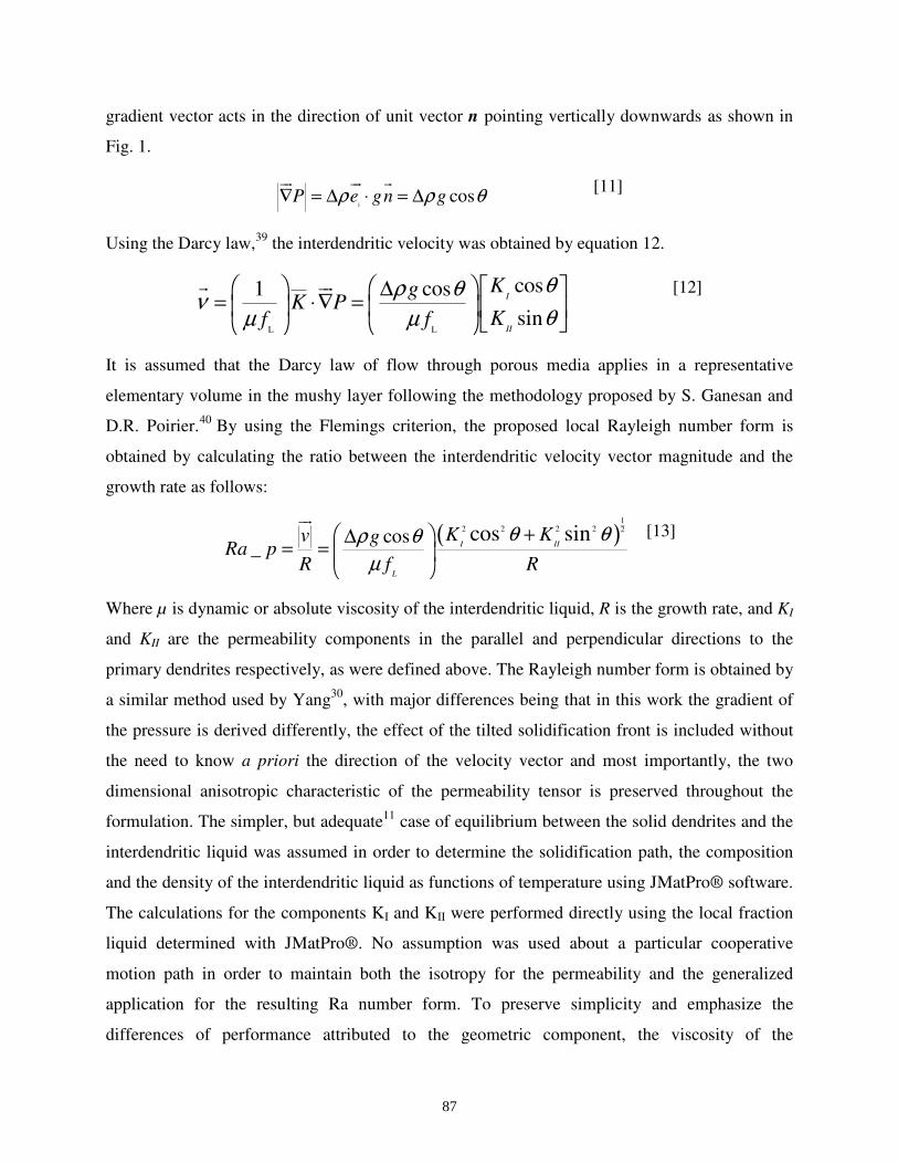
1cosP e gn gρ ρ θ∇ = ∆ ⋅ = ∆
ur ur r [11]
Using the Darcy law,39
the interdendritic velocity was obtained by equation 12.
L L
cos1 cos
sin
I
II
KgK P
Kf f
θρ θνθµ µ
∆= ⋅∇ =
r ur [12]
It is assumed that the Darcy law of flow through porous media applies in a representative
elementary volume in the mushy layer following the methodology proposed by S. Ganesan and
D.R. Poirier.40
By using the Flemings criterion, the proposed local Rayleigh number form is
obtained by calculating the ratio between the interdendritic velocity vector magnitude and the
growth rate as follows:
( )1
2 2 2 2 2
cos_
cos sinI II
L
K Kv gRa p
R f R
θ θρ θµ
+ ∆= =
ur [13]
Where µ is dynamic or absolute viscosity of the interdendritic liquid, R is the growth rate, and KI
and KII are the permeability components in the parallel and perpendicular directions to the
primary dendrites respectively, as were defined above. The Rayleigh number form is obtained by
a similar method used by Yang30
, with major differences being that in this work the gradient of
the pressure is derived differently, the effect of the tilted solidification front is included without
the need to know a priori the direction of the velocity vector and most importantly, the two
dimensional anisotropic characteristic of the permeability tensor is preserved throughout the
formulation. The simpler, but adequate11
case of equilibrium between the solid dendrites and the
interdendritic liquid was assumed in order to determine the solidification path, the composition
and the density of the interdendritic liquid as functions of temperature using JMatPro® software.
The calculations for the components KI and KII were performed directly using the local fraction
liquid determined with JMatPro®. No assumption was used about a particular cooperative
motion path in order to maintain both the isotropy for the permeability and the generalized
application for the resulting Ra number form. To preserve simplicity and emphasize the
differences of performance attributed to the geometric component, the viscosity of the
87

interdendritic liquid was considered constant with the same value for all alloys and temperatures.
The generalized value adopted here was µ= 0.004 in [Kgm-1
s-1
]. The effect of variable viscosity
is critical and its accurate determination should be considered for future work.
Evaluation of the Proposed Form
The criterion based on the maximum proposed local Rayleigh number was evaluated using
experimental data published by two different research groups involving directional solidification
of both commercial and model Ni-based superalloys. The experiments included variations on the
tilt angle, temperature gradient at the mush – bulk liquid boundary and on the growth rate of the
solid crystals. The local Rayleigh numbers were calculated using equation 13 for all experiments.
The compositions of the alloys used for the evaluation are presented in table 1, while the values
for the experimental independent variables and the resulting freckle or no-freckle conditions are
presented in table 2. It is suggested to refer to the original publications for complete details about
the experimental procedures.23 , 37, 38
Table I. Alloy composition for the directional solidification experiments reviewed.
RN902 RN903 RN5010 R4007 718 718 LSi 718 HSi
Ni 54.43 70.57 73.93 Bal. 53.94 54.03 53.41
Cr 19.95 20.09 19.98 18.0 18.48 18.0 18.58
Al - - - 0.5 0.37 0.5 0.38
Ti - - - 1.0 1.08 1.0 0.90
Mo - - - 3.0 3.07 3.0 2.86
Nb 7.13 8.57 6.36 5.0 4.66 5.0 4.05
C 0.014 0.004 0.005 - - 0.008 0.62
Si 0.03 0.01 0.01 - 0.23 0.007 -
Fe 17.75 0.69 0.06 18.0 18.63 18.45 19.45
Table II. Data reported for directional experiments
G (C/mm) R (mm/min) Tilt angle αααα Freckle
RN902
6.12 1.72 50 N
4.09 1.5 50 Y
3.19 1.2 50 Y
2.92 0.8 50 Y
RN903
4.8 1.36 52 N
4.39 1.3 52 N
2.97 1.17 52 N
2.51 1.0 52 Y
88
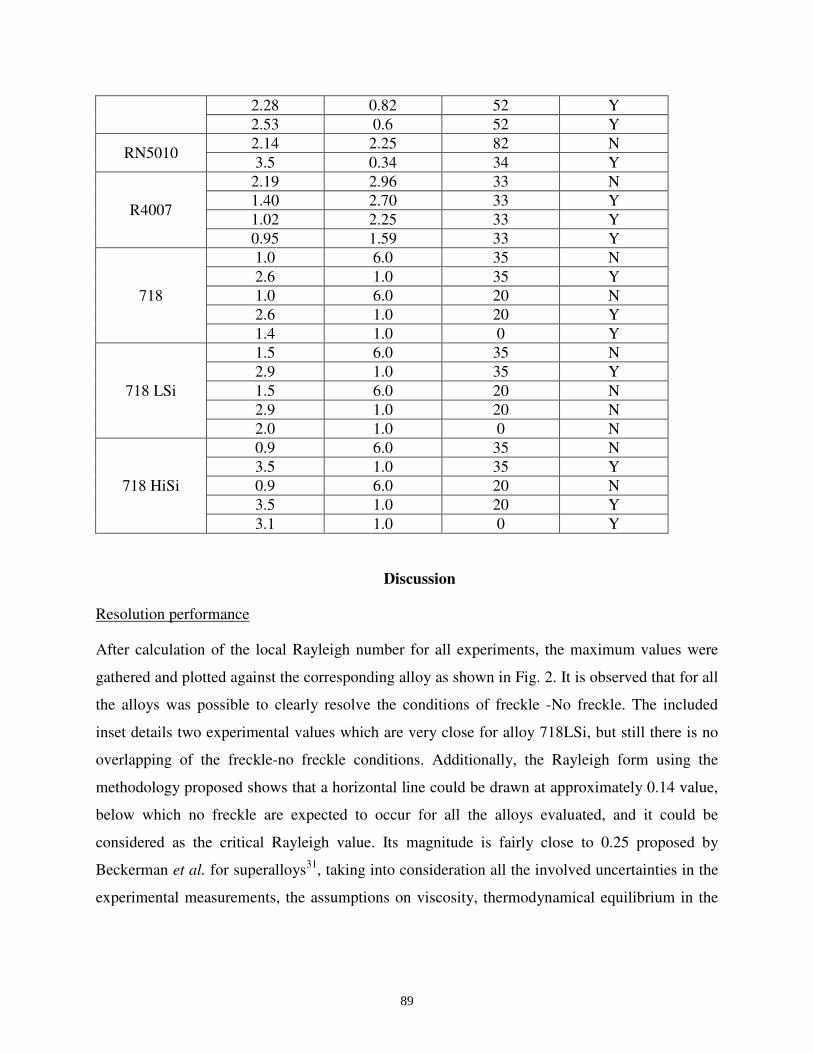
2.28 0.82 52 Y
2.53 0.6 52 Y
RN5010 2.14 2.25 82 N
3.5 0.34 34 Y
R4007
2.19 2.96 33 N
1.40 2.70 33 Y
1.02 2.25 33 Y
0.95 1.59 33 Y
718
1.0 6.0 35 N
2.6 1.0 35 Y
1.0 6.0 20 N
2.6 1.0 20 Y
1.4 1.0 0 Y
718 LSi
1.5 6.0 35 N
2.9 1.0 35 Y
1.5 6.0 20 N
2.9 1.0 20 N
2.0 1.0 0 N
718 HiSi
0.9 6.0 35 N
3.5 1.0 35 Y
0.9 6.0 20 N
3.5 1.0 20 Y
3.1 1.0 0 Y
Discussion
Resolution performance
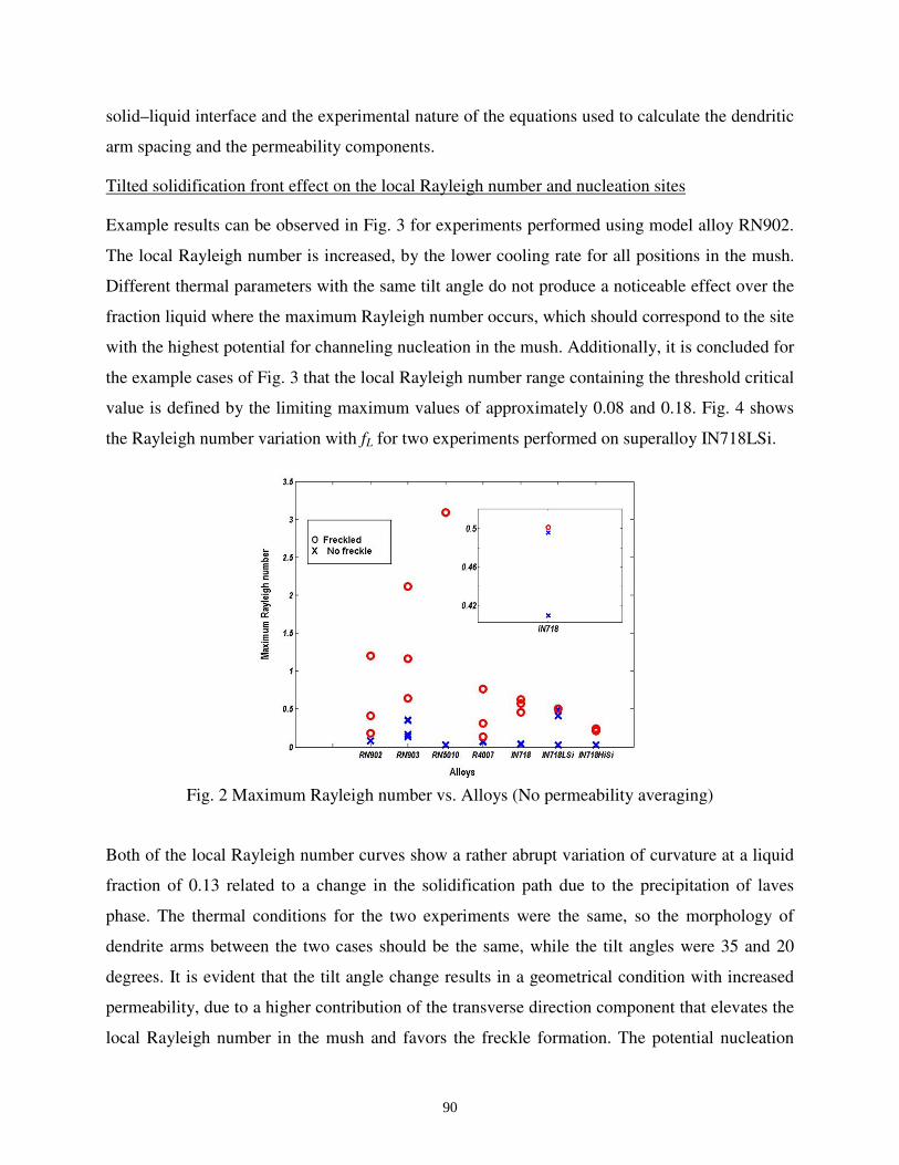
After calculation of the local Rayleigh number for all experiments, the maximum values were
gathered and plotted against the corresponding alloy as shown in Fig. 2. It is observed that for all
the alloys was possible to clearly resolve the conditions of freckle -No freckle. The included
inset details two experimental values which are very close for alloy 718LSi, but still there is no
overlapping of the freckle-no freckle conditions. Additionally, the Rayleigh form using the
methodology proposed shows that a horizontal line could be drawn at approximately 0.14 value,
below which no freckle are expected to occur for all the alloys evaluated, and it could be
considered as the critical Rayleigh value. Its magnitude is fairly close to 0.25 proposed by
Beckerman et al. for superalloys31
, taking into consideration all the involved uncertainties in the
experimental measurements, the assumptions on viscosity, thermodynamical equilibrium in the
89
solid–liquid interface and the experimental nature of the equations used to calculate the dendritic
arm spacing and the permeability components.
Tilted solidification front effect on the local Rayleigh number and nucleation sites
Example results can be observed in Fig. 3 for experiments performed using model alloy RN902.
The local Rayleigh number is increased, by the lower cooling rate for all positions in the mush.
Different thermal parameters with the same tilt angle do not produce a noticeable effect over the
fraction liquid where the maximum Rayleigh number occurs, which should correspond to the site
with the highest potential for channeling nucleation in the mush. Additionally, it is concluded for
the example cases of Fig. 3 that the local Rayleigh number range containing the threshold critical
value is defined by the limiting maximum values of approximately 0.08 and 0.18. Fig. 4 shows
the Rayleigh number variation with fL for two experiments performed on superalloy IN718LSi.
Fig. 2 Maximum Rayleigh number vs. Alloys (No permeability averaging)
Both of the local Rayleigh number curves show a rather abrupt variation of curvature at a liquid
fraction of 0.13 related to a change in the solidification path due to the precipitation of laves
phase. The thermal conditions for the two experiments were the same, so the morphology of
dendrite arms between the two cases should be the same, while the tilt angles were 35 and 20
degrees. It is evident that the tilt angle change results in a geometrical condition with increased
permeability, due to a higher contribution of the transverse direction component that elevates the
local Rayleigh number in the mush and favors the freckle formation. The potential nucleation
90
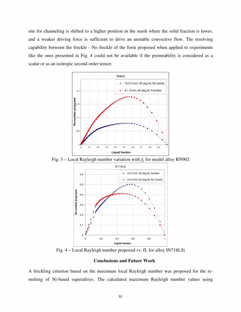
site for channeling is shifted to a higher position in the mush where the solid fraction is lower,
and a weaker driving force is sufficient to drive an unstable convective flow. The resolving
capability between the freckle - No freckle of the form proposed when applied to experiments
like the ones presented in Fig. 4 could not be available if the permeability is considered as a
scalar or as an isotropic second order tensor.
RN902
0
0.05
0.1
0.15
0.2
0 0.1 0.2 0.3 0.4 0.5 0.6 0.7 0.8 0.9 1
Liquid fraction
Ra
nu
mb
er
pro
po
se
d
10.5 C/min, 50 deg tilt, No freckle
6.1 C/min, 50 deg tilt, Freckled
Fig. 3 – Local Rayleigh number variation with fL for model alloy RN902
IN 718LSi
0
0.1
0.2
0.3
0.4
0.5
0.6
0 0.2 0.4 0.6 0.8 1
Liquid fraction
Ra
nu
mb
er
pro
po
sed
2.9 C/min, 35 deg tilt, freckled
2.9 C/min, 20 deg tilt, No Freckle
Fig. 4 – Local Rayleigh number proposed vs. fL for alloy IN718LSi
Conclusions and Future Work
A freckling criterion based on the maximum local Rayleigh number was proposed for the re-
melting of Ni-based superalloys. The calculated maximum Rayleigh number values using
91
experimental data available in the literature provided a clear separation between the observed
freckle - No freckled conditions, and the critical Rayleigh number deduced was approximately
0.14, which is in accordance with a previously proposed value for superalloys derived by a
completely different approach.31
This result evidences the need of further understanding of the
phenomenon, since a critical value should be universal and theoretically near unity. For example,
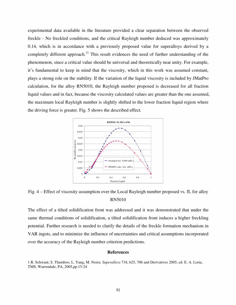
it’s fundamental to keep in mind that the viscosity, which in this work was assumed constant,
plays a strong role on the stability. If the variation of the liquid viscosity is included by JMatPro
calculation, for the alloy RN5010, the Rayleigh number proposed is decreased for all fraction
liquid values and in fact, because the viscosity calculated values are greater than the one assumed,
the maximum local Rayleigh number is slightly shifted to the lower fraction liquid region where
the driving force is greater. Fig. 5 shows the described effect.
RN5010: Ni-20Cr-6Nb
0
0.005
0.01
0.015
0.02
0.025
0.03
0.035
0.04
0 0.2 0.4 0.6 0.8 1
Fraction Liquid
Ra n
um
ber
pro
po
sed
Assumed visc. 0.004 mPa s
JMAtPro calc. visc. mPa s
Fig. 4 – Effect of viscosity assumption over the Local Rayleigh number proposed vs. fL for alloy
RN5010
The effect of a tilted solidification front was addressed and it was demonstrated that under the
same thermal conditions of solidification, a tilted solidification front induces a higher freckling
potential. Further research is needed to clarify the details of the freckle formation mechanism in
VAR ingots, and to minimize the influence of uncertainties and critical assumptions incorporated
over the accuracy of the Rayleigh number criterion predictions.
References
1 R. Schwant, S. Thamboo, L. Yang, M. Norra: Superalloys 718, 625, 706 and Derivatives 2005, ed. E. A. Loria,
TMS, Warrendale, PA, 2005,pp.15-24
92
2 X. Wang, R. M. Ward, M.H. Jacobs and M. D. Barrat: Metal. Mater. Trans. A, 2008, vol. 39A, pp.2981-2989
3 S.M. Copley, A. F. Giamei, S. M. Johnson and M. F. Hornbecker: Metal. Trans., 1970, vol. 1, pp. 2193- 2204
4 D.G. Nielson and F. P. Incropera: Int. J. Heat Mass Transfer, 1991, Vol. 34, pp. 1717-32
5 S. Tait and C. Jaupart: J. Geophys. Res. , 1992, Vol. 97, pp. 6735-56
6 P. D. Genereux and C. A. Borg: Superalloys 2000, eds. , K. A. Green, T.M. Pollock and R. D. Kissinger, TMS,
Champion, PA, 2000, pp.19-27
7 A.K. Sample and A. Hellawell: Metall. Trans. A, 1984, Vol. 15, pp. 2163-73
8 D.G. Nielson and F.P Incropera: Int. J. Heat Mass Transfer, 1993, Vol. 36, pp. 489- 505
9 D.G. Nielson and F.P. Incropera: Exp. Heat Transfer, 1993,Vol. 6, pp. 131-55
10 C. Frueh, D.R. Poirier, R.G. Erdmann, S. D. Felicelli: Mater. Sci. Eng. A, 2003, Vol. 345, pp.72-80
11 M.C. Schneider and C. Beckermann: Int. J. Heat Mass Transfer, 1995, Vol. 38, pp.3455-73
12 M.G. Worster: J. Fluid Mech., 1992, Vol. 237, pp. 649-69
13 P.W. Emms: J. Eng. Math., 1998, Vol.33, pp.175-200
14 S. Tait, K. Jahrling, C. Jaupart: Nature, 1992, Vol. 359, pp.406-08
15 A. Mitchell: Mater. Sci. Eng. A, 2005, 413-414, pp. 10-18
16 I. G. Hwang and C. K. Choi: Korean J. Chem. Eng., 2008, Vol. 25, pp. 199-02
17 James H. Van Den Avyle, John A. Brooks, and Adam C. Powell: JOM,1998,vol.50(3), pp. 22-25
18 P. Auburtin, S. L. Cockcroft, A. Mitchell, A.J. Schmalz: Superalloys 718,625, 706 and various Derivatives, E. A.
Loria ed., TMS, Pittsburgh, PA, 1997, pp.47-54
19 P. Auburtin, S. L. Cockcroft, A. Mitchell: Superalloys 1996, R.D. Kissinger, D.J. Deye, D.L. Anton, and A.D.
Cetel, eds., TMS, Champion, PA, 1996, pp. 443-50
20 A. D. Patel, R. S. Minisandram and D. G. Evans: Superalloys 2004, K.A. Green, T.M. Pollock, H. Harada, T.E.
Howson, R.C. Reed, J.J. Schirra, and S. Walston, eds., TMS, Warrendale, PA, pp. 917-924
21 D. Zagrebelnyy and M. J. M. krane: Metall. Mater. Trans. B, 2009, Vol. 40, pp. 281- 288
22 L. Yuan, P. D. Lee, G. Djambazov and K. Pericleous: International symposium on liquid metal processing and
casting, 2009, eds. Peter Lee, Alec Mitchell, and Rod Williams, TMS, 2009, Santa Fe, New Mexico, pp. 39-46
23 W.H. Yang, J. J. deBarbadillo, K. Morita, T. Suzuki, W. Chen, K. M. Chang: JOM, 2004, Vol. 56 (9), pp. 56-61
24 K. Kajikawa, T. Sato and H. Yamada: International symposium on liquid metal processing and casting, 2009, eds.
Peter Lee, Alec Mitchell, and Rod Williams, TMS, 2009, Santa Fe, New Mexico, pp. 327-335
25 P. Auburtin, T. Wang, S.L. Cockcroft and A. Mitchell: Metall. Mater. Trans. B, 2000, vol.31B, pp.801-811
26 M.C. Flemings and G.E. Nereo: Trans. TMS-AIME, 1967, vol.239, pp.1449-61.
93
27 R. Mehrabian, M. Keane and M.C. Flemings: Metall. Trans., 1970, vol.1, pp. 1209-20.
28 M. G. Worster: Annu. Rev. Fluid Mech. , 1997, Vol. 29, pp. 91-122
29 M. G. Worster: J. Fluid Mech., vol. 224. 1991, pp. 335-359
30 W. H. Yang, W. Chen, K. M. Chang, S. Mannan, J. deBarbadillo: Metall. Mater. Trans. Vol. 31A, 2001, pp. 397-
406
31 C. Beckermann, J. P. Gu and W. J. Boettinger: Metall. Mater. Trans. A, 2000, Vol. 31, pp. 2545- 57
32 T.M. Pollock and W.H. Murphy: Metall. Mater. Trans. A, 1996, Vol. 27, pp. 1081-1094
33 J. C. Ramirez and C. Beckermann: Metall. Mater. Trans. A, 2003, Vol. 34, pp. 1525-36
34 D.R. Poirier: Metall. Trans B, 1987, vol.18B, pp.245-55
35 J. R. Sarazin and A. Hellawell: Metall. Trans. A, 1988, vol. 19A, pp.1861-1871
36 A. E. Scheidegger: The physics of flow through porous media, revised edition, The MacMillan Company , New
York, 1960, pp.76-79
37 P. Auburtin, S.L. Cockcroft, A. Mitchell and T. Wang: Superalloys 2000, eds. T. M. Pollock, R. D. Kissinger, R.
R. Bowman, K. A. Green, M. McLean, S. Olson and J. J. Schirra, TMS, 2000, Champion , PA, pp.255-261
38 P. Auburtin: PhD. Thesis, University of British Columbia, Vancouver, BC, Canada, Aug. 1998.
39 M.S. Bhat, D.R. Poirier, J.C. Heinrich and D. Nagelhout: Scripta Metall. Mater., 1994, vol. 31, pp.339-344
40 S. Ganesan and D.R. Poirier: Metall. Trans. B, 1990, vol. 21B, pp. 173-181
94


![special stroller · 2020. 6. 9. · RACER ® special stroller ... X Backrest tilt angle [°] 90–140 90–135 90–140 90–140 Z Footplate tilt angle [°] 100–120 100–125 100–120](https://static.fdocuments.in/doc/165x107/5fe3fef5034a18344b68cb0d/special-stroller-2020-6-9-racer-special-stroller-x-backrest-tilt-angle.jpg)