Solid State Relays Phase with Integrated Heatsink … · 2018-04-30 · •2-pole and 3-pole analog...
30
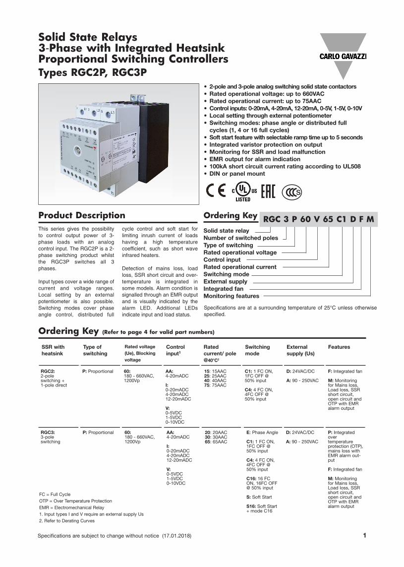
Specifications are subject to change without notice (17.01.2018) 1 Solid state relay Number of switched poles Type of switching Rated operational voltage Control input Rated operational current Switching mode External supply Integrated fan Monitoring features • 2-pole and 3-pole analog switching solid state contactors • Rated operational voltage: up to 660VAC • Rated operational current: up to 75AAC • Control inputs: 0-20mA, 4-20mA, 12-20mA, 0-5V, 1-5V, 0-10V • Local setting through external potentiometer • Switching modes: phase angle or distributed full cycles (1, 4 or 16 full cycles) • Soft start feature with selectable ramp time up to 5 seconds • Integrated varistor protection on output • Monitoring for SSR and load malfunction • EMR output for alarm indication • 100kA short circuit current rating according to UL508 • DIN or panel mount Product Description Ordering Key This series gives the possibility to control output power of 3- phase loads with an analog control input. The RGC2P is a 2- phase switching product whilst the RGC3P switches all 3 phases. Input types cover a wide range of current and voltage ranges. Local setting by an external potentiometer is also possible. Switching modes cover phase angle control, distributed full cycle control and soft start for limiting inrush current of loads having a high temperature coefficient, such as short wave infrared heaters. Detection of mains loss, load loss, SSR short circuit and over- temperature is integrated in some models. Alarm condition is signalled through an EMR output and is visually indicated by the alarm LED. Additional LEDs indicate input and load status. Solid State Relays 3-Phase with Integrated Heatsink Proportional Switching Controllers Types RGC2P, RGC3P Ordering Key (Refer to page 4 for valid part numbers) RGC 3 P 60 V 65 C1 D F M RGC2: 2-pole switching + 1-pole direct P: Proportional 60: 180 - 660VAC, 1200Vp AA: 4-20mADC I: 0-20mADC 4-20mADC 12-20mADC V: 0-5VDC 1-5VDC 0-10VDC C1: 1 FC ON, 1FC OFF @ 50% input C4: 4 FC ON, 4FC OFF @ 50% input D: 24VAC/DC A: 90 - 250VAC F: Integrated fan M: Monitoring for Mains loss, Load loss, SSR short circuit, open circuit and OTP with EMR alarm output SSR with heatsink Type of switching Rated voltage (Ue), Blocking voltage Control input 1 Rated current/ pole @40°C 2 Switching mode External supply (Us) Features 15: 15AAC 25: 25AAC 40: 40AAC 75: 75AAC RGC3: 3-pole switching P: Proportional 60: 180 - 660VAC, 1200Vp AA: 4-20mADC I: 0-20mADC 4-20mADC 12-20mADC V: 0-5VDC 1-5VDC 0-10VDC E: Phase Angle C1: 1 FC ON, 1FC OFF @ 50% input C4: 4 FC ON, 4FC OFF @ 50% input C16: 16 FC ON, 16FC OFF @ 50% input S: Soft Start S16: Soft Start + mode C16 D: 24VAC/DC A: 90 - 250VAC P: Integrated over temperature protection (OTP), mains loss with EMR alarm out- put F: Integrated fan M: Monitoring for Mains loss, Load loss, SSR short circuit, open circuit and OTP with EMR alarm output Specifications are at a surrounding temperature of 25°C unless otherwise specified. 20: 20AAC 30: 30AAC 65: 65AAC FC = Full Cycle OTP = Over Temperature Protection EMR = Electromechanical Relay 1. Input types I and V require an external supply Us 2. Refer to Derating Curves s
Transcript of Solid State Relays Phase with Integrated Heatsink … · 2018-04-30 · •2-pole and 3-pole analog...
Specifications are subject to change without notice (17.01.2018) 1
Solid state relayNumber of switched polesType of switchingRated operational voltageControl inputRated operational currentSwitching modeExternal supplyIntegrated fanMonitoring features
• 2-pole and 3-pole analog switching solid state contactors • Rated operational voltage: up to 660VAC• Rated operational current: up to 75AAC• Control inputs: 0-20mA, 4-20mA, 12-20mA, 0-5V, 1-5V, 0-10V• Local setting through external potentiometer• Switching modes: phase angle or distributed full cycles (1, 4 or 16 full cycles)
• Soft start feature with selectable ramp time up to 5 seconds• Integrated varistor protection on output• Monitoring for SSR and load malfunction• EMR output for alarm indication• 100kA short circuit current rating according to UL508• DIN or panel mount
Product Description Ordering KeyThis series gives the possibilityto control output power of 3-phase loads with an analogcontrol input. The RGC2P is a 2-phase switching product whilstthe RGC3P switches all 3phases.
Input types cover a wide range ofcurrent and voltage ranges.Local setting by an externalpotentiometer is also possible.Switching modes cover phaseangle control, distributed full
cycle control and soft start forlimiting inrush current of loadshaving a high temperaturecoefficient, such as short waveinfrared heaters.
Detection of mains loss, loadloss, SSR short circuit and over-temperature is integrated insome models. Alarm condition issignalled through an EMR outputand is visually indicated by thealarm LED. Additional LEDsindicate input and load status.
Solid State Relays3-Phase with Integrated HeatsinkProportional Switching ControllersTypes RGC2P, RGC3P
Ordering Key (Refer to page 4 for valid part numbers)
RGC 3 P 60 V 65 C1 D F M
RGC2:2-pole switching +1-pole direct
P: Proportional 60: 180 - 660VAC,1200Vp
AA: 4-20mADC
I:0-20mADC4-20mADC12-20mADC
V:0-5VDC1-5VDC0-10VDC
C1: 1 FC ON,1FC OFF @50% input
C4: 4 FC ON,4FC OFF @50% input
D: 24VAC/DC
A: 90 - 250VAC
F: Integrated fan
M: Monitoringfor Mains loss,Load loss, SSRshort circuit,open circuit andOTP with EMRalarm output
SSR withheatsink
Type of switching
Rated voltage(Ue), Blockingvoltage
Controlinput1
Rated current/ pole@40°C2
Switching mode
External supply (Us)
Features
15: 15AAC25: 25AAC40: 40AAC75: 75AAC
RGC3:3-pole switching
P: Proportional 60: 180 - 660VAC,1200Vp
AA: 4-20mADC
I:0-20mADC4-20mADC12-20mADC
V:0-5VDC1-5VDC0-10VDC
E: Phase Angle
C1: 1 FC ON,1FC OFF @50% input
C4: 4 FC ON,4FC OFF @50% input
C16: 16 FCON, 16FC OFF@ 50% input
S: Soft Start
S16: Soft Start+ mode C16
D: 24VAC/DC
A: 90 - 250VAC
P: Integratedover temperature protection (OTP),mains loss withEMR alarm out-put
F: Integrated fan
M: Monitoringfor Mains loss,Load loss, SSRshort circuit,open circuit andOTP with EMRalarm output
Specifications are at a surrounding temperature of 25°C unless otherwisespecified.
20: 20AAC30: 30AAC65: 65AAC
FC = Full CycleOTP = Over Temperature ProtectionEMR = Electromechanical Relay1. Input types I and V require an external supply Us2. Refer to Derating Curves
s
2 Specifications are subject to change without notice (17.01.2018)
RGC2P, RGC3P
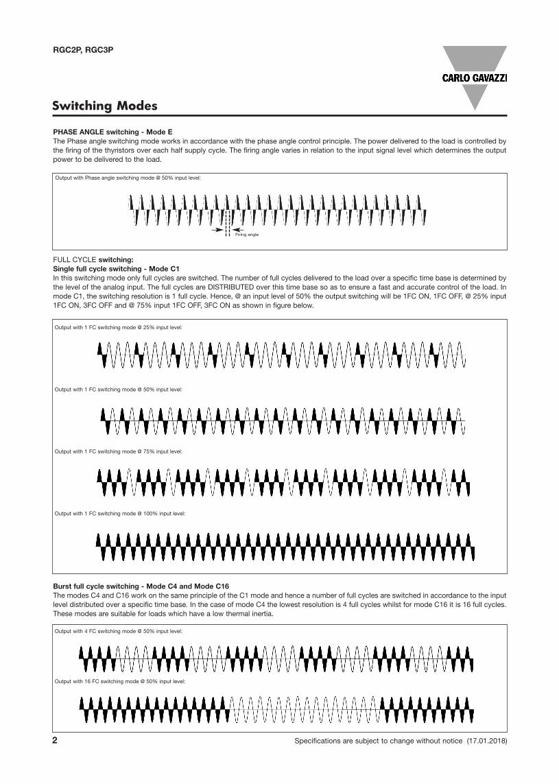
Switching Modes
Firing angle
PHASE ANGLE switching - Mode EThe Phase angle switching mode works in accordance with the phase angle control principle. The power delivered to the load is controlled bythe firing of the thyristors over each half supply cycle. The firing angle varies in relation to the input signal level which determines the outputpower to be delivered to the load.
Output with Phase angle switching mode @ 50% input level:
Full cycle switching:Single full cycle switching - Mode C1 In this switching mode only full cycles are switched. The number of full cycles delivered to the load over a specific time base is determined bythe level of the analog input. The full cycles are DISTRIBUTED over this time base so as to ensure a fast and accurate control of the load. Inmode C1, the switching resolution is 1 full cycle. Hence, @ an input level of 50% the output switching will be 1FC ON, 1FC OFF, @ 25% input1FC ON, 3FC OFF and @ 75% input 1FC OFF, 3FC ON as shown in figure below.
Output with 1 FC switching mode @ 25% input level:
Output with 1 FC switching mode @ 50% input level:
Output with 1 FC switching mode @ 75% input level:
Output with 1 FC switching mode @ 100% input level:
Burst full cycle switching - Mode C4 and Mode C16The modes C4 and C16 work on the same principle of the C1 mode and hence a number of full cycles are switched in accordance to the inputlevel distributed over a specific time base. In the case of mode C4 the lowest resolution is 4 full cycles whilst for mode C16 it is 16 full cycles.These modes are suitable for loads which have a low thermal inertia.
Output with 4 FC switching mode @ 50% input level:
Output with 16 FC switching mode @ 50% input level:

Specifications are subject to change without notice (17.01.2018) 3
RGC2P, RGC3P
Switching Modes (continued)
SoFt Start switching:In this mode the thyristor firing angle is gradually increased in order to apply the voltage (and current) to the load smoothly and thus reducethe start-up current of loads which have a high cold to hot resistance ratio such as short wave infrared heaters.
Soft start with digital input - Mode SOn power up, the RGC3P60V..S.. performs a soft start as soon as a control input is applied. The ramp time can be set to a maximum of 5seconds through an onboard potentiometer. After the ramp is completed, full cycles are delivered to the output as long as a control voltage(between 5 - 10V) is present on terminals A1-A4. Soft start is not performed every time the control input is applied but only in the cases wherefiring has been cut off for more than 5 seconds. If for some reason ramping is stopped before ramp completion, a start is assumed to havebeen performed and hence the 5 seconds count start once ramping is stopped.
Soft start with analog input - Mode S16This switching mode is a combination of 2 switching modes described above and hence soft start with mode S and full cycle control with modeC16. The RGC3P60V..S16 switching mode works on the principle of the mode C16 but on power up soft starting is performed to limit inrushcurrents loads which have a low resistance when cold. After the soft start is completed, where ramping time can be set to maximum of 5seconds through an onboard potentiometer, the mode C16 comes into affect. Full cycles are thus delivered to the load in accorancde to theinput level. Soft starting is performed on power up and in case firing has been cut in the previous 5 seconds. If for some reason ramping isstopped before ramp completion, a start is assumed to have been performed and hence the 5 seconds count start once ramping is stopped.

4 Specifications are subject to change without notice (17.01.2018)
RGC2P, RGC3P
Selection Guide: RGC2P
Current rating@ 40°C
Input type
External supply
Switching mode
E C1 C4 C16 S S16
15AAC1,800A²s
AA - - RGC2P60AA15C1 - - - -
25AAC1,800A²s
AA - - RGC2P60AA25C1 - - - -
I DC - RGC2P60I25C1DM RGC2P60I25C4DM - - -
V DC - RGC2P60V25C1DM - - - -
40AAC6,600A²s
AA - - RGC2P60AA40C1 - - - -
I DC - RGC2P60I40C1DM RGC2P60I40C4DM - - -
V DC - RGC2P60V40C1DM - - - -
75AAC15,000A²s
I DC - RGC2P60I75C1DFM RGC2P60I75C4DFM - - -
AC - RGC2P60I75C1AFM RGC2P60I75C4AFM - - -
V DC - RGC2P60V75C1DFM - - - -
AC - RGC2P60V75C1AFM - - - -
Current rating@ 40°C
Inputtype
Externalsupply
Switching mode
E C1 C4 C16 S S16
20AAC1,800A²s
AA - RGC3P60AA20E RGC3P60AA20C1 - - - -
I DC RGC3P60I20EDP RGC3P60I20C1DM RGC3P60I20C4DM RGC3P60I20C16DM - -
V DC RGC3P60V20EDP RGC3P60V20C1DM RGC3P60V20C4DM RGC3P60V20C16DM - RGC3P60V20S16DM
5-10Vdigital i/p DC - - - - RGC3P60V20SDM -
30AAC6,600A²s
AA - RGC3P60AA30E RGC3P60AA30C1 - - - -
I DC RGC3P60I30EDP RGC3P60I30C1DM RGC3P60I30C4DM RGC3P60I30C16DM - -
AC RGC3P60I30EAP RGC3P60I30C1AM RGC3P60I30C4AM RGC3P60I30C16AM - -
V DC RGC3P60V30EDP RGC3P60V30C1DM RGC3P60V30C4DM RGC3P60V30C16DM - RGC3P60V30S16DM
AC RGC3P60V30EAP RGC3P60V30C1AM RGC3P60V30C4AM RGC3P60V30C16AM - -
5-10Vdigital i/p
DC - - - - RGC3P60V30SDM -
65AAC15,000A²s
I DC RGC3P60I65EDFP RGC3P60I65C1DFM RGC3P60I65C4DFM RGC3P60I65C16DFM - -
AC RGC3P60I65EAFP RGC3P60I65C1AFM RGC3P60I65C4AFM RGC3P60I65C16AFM - -
V DC RGC3P60V65EDFP RGC3P60V65C1DFM RGC3P60V65C4DFM RGC3P60V65C16DFM - RGC3P60V65S16DFM
AC RGC3P60V65EAFP RGC3P60V65C1AFM RGC3P60V65C4AFM RGC3P60V65C16AFM - -
5-10Vdigital i/p
DC - - - - RGC3P60V65SDFM -
Input typeAA: 4-20 mADCI: 0-20, 4-20, 12-20 mADCV: 0-10, 0-5, 1-5 VDC
External supplyDC: 24VAC/DCAC: 90-250VAC
Switching modeE: Phase AngleC1: 1 Full CycleC4: 4 Full CyclesC16: 16 Full CyclesS: Soft StartS16: Soft Start + 16 Full Cycles
Selection Guide: RGC3P
Specifications are subject to change without notice (17.01.2018) 5
RGC2P, RGC3P
3: Refer to LED Indications
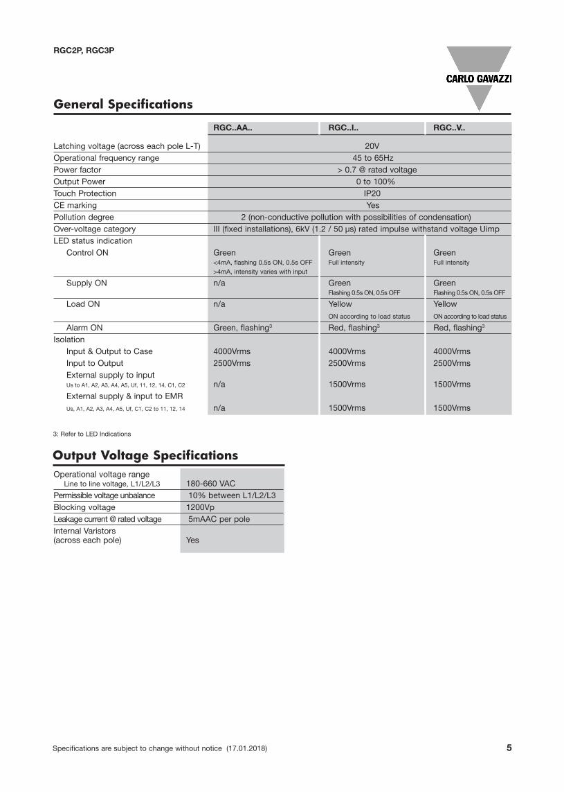
General Specifications
RGC..AA.. RGC..I.. RGC..V..
Latching voltage (across each pole L-T) �20VOperational frequency range 45 to 65HzPower factor > 0.7 @ rated voltageOutput Power 0 to 100%Touch Protection IP20CE marking YesPollution degree 2 (non-conductive pollution with possibilities of condensation)Over-voltage category III (fixed installations), 6kV (1.2 / 50�µs) rated impulse withstand voltage UimpLED status indication
Control ON Green Green Green<4mA, flashing 0.5s ON, 0.5s OFF Full intensity Full intensity>4mA, intensity varies with input
Supply ON n/a Green GreenFlashing 0.5s ON, 0.5s OFF Flashing 0.5s ON, 0.5s OFF
Load ON n/a Yellow YellowON according to load status ON according to load status
Alarm ON Green, flashing3 Red, flashing3 Red, flashing3
Isolation Input & Output to Case 4000Vrms 4000Vrms 4000VrmsInput to Output 2500Vrms 2500Vrms 2500VrmsExternal supply to inputUs to A1, A2, A3, A4, A5, Uf, 11, 12, 14, C1, C2 n/a 1500Vrms 1500VrmsExternal supply & input to EMRUs, A1, A2, A3, A4, A5, Uf, C1, C2 to 11, 12, 14 n/a 1500Vrms 1500Vrms
Output Voltage SpecificationsOperational voltage range
Line to line voltage, L1/L2/L3 180-660 VACPermissible voltage unbalance �10% between L1/L2/L3Blocking voltage 1200VpLeakage current @ rated voltage �5mAAC per poleInternal Varistors (across each pole) Yes

6 Specifications are subject to change without notice (17.01.2018)
Output Specifications: RGC2 RGC2..15 RGC2..25 RGC2..40 RGC2..75
Rated operational current per pole4
AC-51 @ Ta=25°C 15 AAC 32 AAC 50 AAC 85 AACAC-51 @ Ta=40°C 15 AAC 27 AAC 40 AAC 75 AACAC-55b @ Ta=40°C5 15 AAC 27 AAC 40 AAC 75 AAC
Minimum operational current 500 mAAC 500 mAAC 1AAC 1 AAC
Number of starts5 130 35 10 240
Rep. Overload Current PF = 0.7UL508: Ta=40°C, tON=1s, tOFF=9s, 50cycles 61 AAC 61 AAC 107 AAC 154 AAC
Maximum transient surge current (Itsm), t=10ms 600 Ap 600 Ap 1150 Ap 1750 Ap
I²t for fusing (t=10ms), minimum 1800 A²s 1800 A²s 6600 A²s 15000 A²s
Critical dv/dt (@ Tj init = 40°C) 1000 V/µs 1000 V/µs 1000 V/µs 1000 V/µs
4: Refer to Derating Curves5: Overload profile for AC-55b, Ie: AC-55b: 6x Ie - 0.2: 80 - x, where Ie = nominal current (AAC), 6xIe = overload current (AAC), 0.2 = duration of overload current (s), 80 = ON duty cycle (%), x= number of starts. The overload profile for RGC2..75 is AC-55b: 3.2x Ie - 0.2: 80 - x
RGC2P, RGC3P
Output Specifications: RGC3 RGC3..20 RGC3..30 RGC3..65
Rated operational current per pole4
AC-51 @ Ta=25°C 25 AAC 37 AAC 71 AACAC-51 @ Ta=40°C 20 AAC 30 AAC 66 AACAC-55b @ Ta=40°C5 20 AAC 30 AAC 66 AAC
Minimum operational current 500 mACC 1AAC 1 AAC
Number of starts5 140 18 230
Rep. Overload Current PF = 0.7 UL508: Ta=40°C, tON=1s, tOFF=9s, 50cycles 61 AAC 107 AAC 154 AAC
Maximum transient surge current (Itsm), t=10ms 600 Ap 1150 Ap 1750 Ap
I²t for fusing (t=10ms), minimum 1800 A²s 6600 A²s 15000 A²s
Critical dv/dt (@ Tj init = 40°C) 1000 V/µs 1000 V/µs 1000 V/µs
4: Refer to Derating Curves5: Overload profile for AC-55b, Ie: AC-55b: 6x Ie - 0.2: 80 - x, where Ie = nominal current (AAC), 6xIe = overload current (AAC), 0.2 = duration of overload current (s), 80 = ON duty cycle (%), x= number of starts. The overload profile for RGC3..65 is AC-55b: 3.6x Ie - 0.2: 80 - x
Specifications are subject to change without notice (17.01.2018) 7
RGC2P, RGC3P
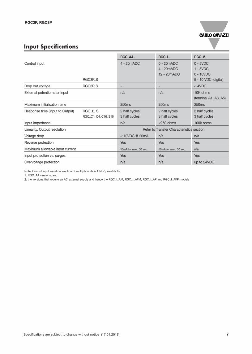
Input Specifications
RGC..AA.. RGC..I.. RGC..V..
Control input 4 - 20mADC 0 - 20mADC 0 - 5VDC4 - 20mADC 1 - 5VDC12 - 20mADC 0 - 10VDC
RGC3P..S 5 - 10 VDC (digital)
Drop out voltage RGC3P..S - - < 4VDC
External potentiometer input n/a n/a 10K ohms (terminal A1, A3, A5)
Maximum initialisation time 250ms 250ms 250ms
Response time (Input to Output) RGC..E, S 2 half cycles 2 half cycles 2 half cyclesRGC..C1, C4, C16, S16 3 half cycles 3 half cycles 3 half cycles
Input impedance n/a <250 ohms 100k ohms
Linearity, Output resolution Refer to Transfer Characteristics section
Voltage drop < 10VDC @ 20mA n/a n/a
Reverse protection Yes Yes Yes
Maximum allowable input current 50mA for max. 30 sec. 50mA for max. 30 sec. n/a
Input protection vs. surges Yes Yes Yes
Overvoltage protection n/a n/a up to 24VDC
Note: Control input serial connection of multiple units is ONLY possible for:1. RGC..AA versions, and2. the versions that require an AC external supply and hence the RGC..I..AM, RGC..I..AFM, RGC..I..AP and RGC..I..AFP models

8 Specifications are subject to change without notice (17.01.2018)
Transfer Characteristics
0
10
20
30
40
50
60
70
80
90
100
0 10 20 30 40 50 60 70 80 90 100
% O
utpu
t Pow
er
% Control Input
%OutputGoing Down
%OutputGoing Up
0
10
20
30
40
50
60
70
80
90
100
0 10 20 30 40 50 60 70 80 90 100
% Ou
tput
Powe
r
% Control Input
%OutputGoing Up
%OutputGoing Down
0
10
20
30
40
50
60
70
80
90
100
0 10 20 30 40 50 60 70 80 90 100
% O
utp
ut
Po
we
r
% Control Input
%OutputGoing Up
%OutputGoing Down
RGC2P, RGC3P
1 Full cycle switching mode: RGC...C1
4 Full cycles switching mode: RGC...C4
16 Full cycles switching mode: RGC...C16
Increasing %output power
Decreasing %output power
Increasing %output power
Decreasing %output power
Increasing %output power
Decreasing %output power
% Control Input
% Control Input
% Control Input
% Output Power
% Output Power
% Output Power
0
10
0 10 20 30 40 50 60 70 80 90 100
%
0
10
2
0 10 20 30 40 50 60 70 80 90 100
%
0
10
20
3
0 10 20 30 40 50 60 70 80 90 100
%
Specifications are subject to change without notice (17.01.2018) 9
Transfer Characteristics
RGC2P, RGC3P
Phase Angle switching mode: RGC3P..E
3-phase, 3-wire systems
3-phase, 4-wire systems
0
20
40
60
80
100
0 10 20 30 40 50 60 70 80 90 100
%Outpu
tPow
er
% Control Input
PF=0.7
PF=0.8
PF=0.9
PF=1
0
20
40
60
80
100
0 20 40 60 80 100
%Ou
tput
Power
% Control Input
PF=0.7
PF=0.8
PF=0.9
PF=1
10 Specifications are subject to change without notice (17.01.2018)
RGC2P, RGC3P
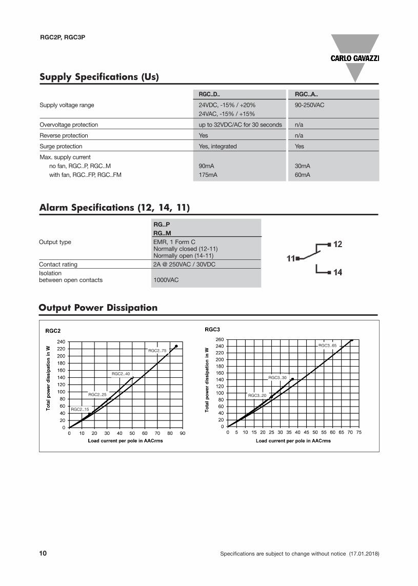
Supply Specifications (Us)
RGC..D.. RGC..A..
Supply voltage range 24VDC, -15% / +20% 90-250VAC24VAC, -15% / +15%
Overvoltage protection up to 32VDC/AC for 30 seconds n/a
Reverse protection Yes n/a
Surge protection Yes, integrated Yes
Max. supply currentno fan, RGC..P, RGC..M 90mA 30mAwith fan, RGC..FP, RGC..FM 175mA 60mA
Alarm Specifications (12, 14, 11)
RG..PRG..M
Output type EMR, 1 Form CNormally closed (12-11)Normally open (14-11)
Contact rating 2A @ 250VAC / 30VDCIsolationbetween open contacts 1000VAC
Output Power Dissipation
RGC2..75
RGC2..40
RGC2..25
RGC2..15
RGC3..65
RGC3..30
RGC3..20

Specifications are subject to change without notice (17.01.2018) 11
RGC2P, RGC3P
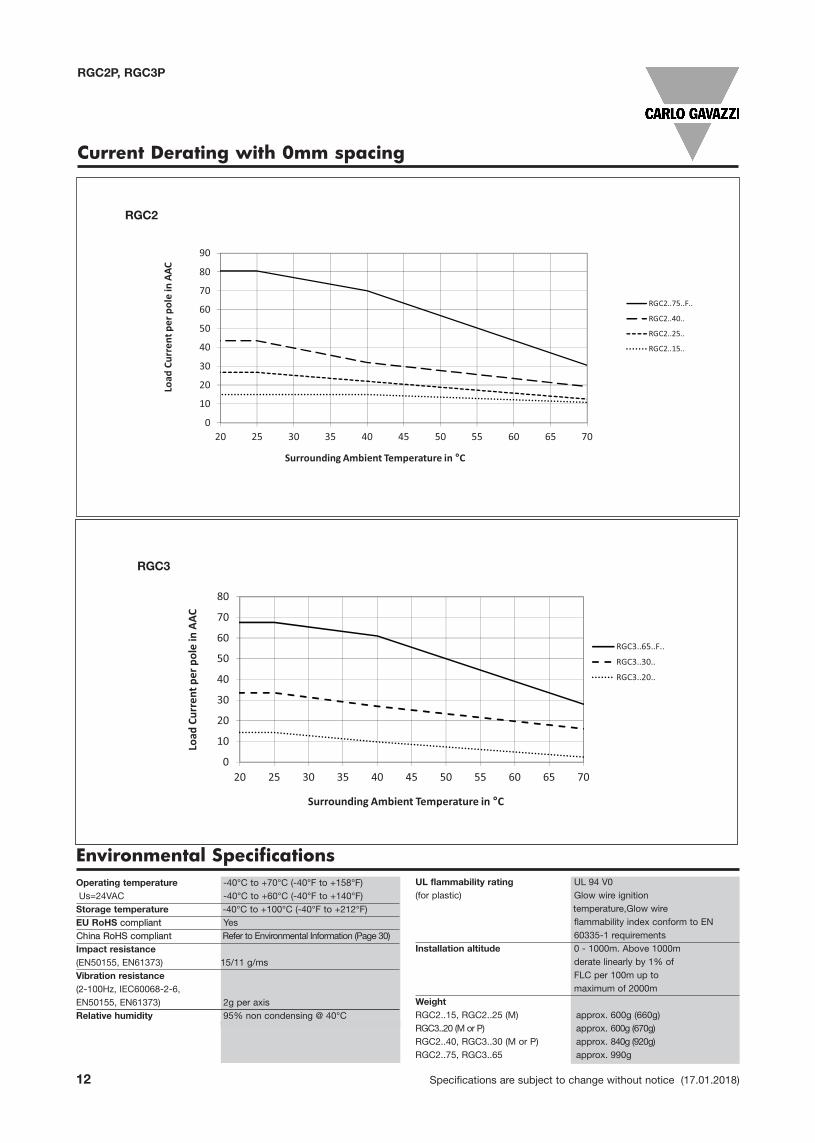
Current Derating
RGC2
RGC3
0
10
20
30
40
50
60
70
80
90
20 25 30 35 40 45 50 55 60 65 70
Load
Cur
rent
per
pol
e in
AAC
Surrounding Ambient Temperature in °C
RGC2..75..F..
RGC2..40..
RGC2..25..
RGC2..15
0
10
20
30
40
50
60
70
80
20 25 30 35 40 45 50 55 60 65 70
Load
Cur
rent
per
pol
e in
AAC
Surrounding Ambient Temperature in °C
RGC3..65..F..
RGC3..30..
RGC3..20..
Note: Versions that utilise 24VAC external supply (Us) are limited to a maximum operating temperature of 60˚C (140˚F)
Note: Versions that utilise 24VAC external supply (Us) are limited to a maximum operating temperature of 60˚C (140˚F)
12 Specifications are subject to change without notice (17.01.2018)
RGC2P, RGC3P
Current Derating with 0mm spacing
Temp Current Temp Current Temp Current Temp Current Temp C
0°C 26.8A 0°C 43.5 0°C 80.5 0°C 15.0A 0°C 4
25°C 26.8A 25°C 43.5 25°C 80.5 25°C 15.0A 25°C 4
40°C 22.0A 40°C 32 40°C 70 40°C 15.0A
80°C 9.5A 80°C 15 70°C 30.5 80°C 9.5A 40°C 32.0A 40°C 40.0
80°C 15.0A 80°C 21.0
RGC2..75..F.. RGC2..15..
RGC2_25
RGC2..25.. RGC2..40.. 0mm
0
10
20
30
40
50
60
70
80
90
20 25 30 35 40 45 50 55 60 65 70
Load
Cur
rent
per
pol
e in
AAC
Surrounding Ambient Temperature in °C
RGC2
RGC2..75..F..
RGC2..40..
RGC2..25..
RGC2..15..
pmeTtnerruCpmeT Current Temp Current Temp Current Temp Current
A5.76C°0A5.76C°0A5.53C°0A5.33C°0A3.41C°0
A5.76C°52A5.76C°52A5.53C°52A5.33C°52A3.41C°52
A0.16C°04A0.16C°04A5.53C°04A0.72C°04A8.9C°04
A0.03C°06A0.82C°07A3.02C°08A5.21C°08A0.0C°08
,FA56..3CGR..F..56..3CGR04..3CGR..03..3CGR..02..3CGR AFM
0
10
20
30
40
50
60
70
80
20 25 30 35 40 45 50 55 60 65 70
Load
Cur
rent
per
pol
e in
AAC
Surrounding Ambient Temperature in °C
RGC3
RGC3..65..F..
RGC3..30..
RGC3..20..
RGC2
RGC3
Environmental SpecificationsOperating temperature -40°C to +70°C (-40°F to +158°F)Us=24VAC -40°C to +60°C (-40°F to +140°F)Storage temperature -40°C to +100°C (-40°F to +212°F)EU RoHS compliant YesChina RoHS compliant Refer to Environmental Information (Page 30)Impact resistance(EN50155, EN61373) 15/11 g/msVibration resistance(2-100Hz, IEC60068-2-6,EN50155, EN61373) 2g per axisRelative humidity 95% non condensing @ 40°C
UL flammability rating UL 94 V0(for plastic) Glow wire ignition
temperature,Glow wire flammability index conform to EN 60335-1 requirements
Installation altitude 0 - 1000m. Above 1000m derate linearly by 1% of FLC per 100m up to maximum of 2000m
WeightRGC2..15, RGC2..25 (M) approx. 600g (660g)RGC3..20 (M or P) approx. 600g (670g)RGC2..40, RGC3..30 (M or P) approx. 840g (920g)RGC2..75, RGC3..65 approx. 990g
Specifications are subject to change without notice (17.01.2018) 13
RGC2P, RGC3P
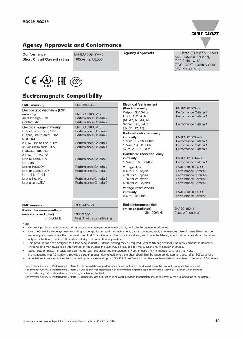
Agency Approvals and ConformanceConformance EN/IEC 60947-4-3Short Circuit Current rating 100kArms, UL508
Agency Approvals UL Listed (E172877), UL508cUL Listed (E172877), C22.2 No.14-13 CCC, GB/T 14048.5-2008 (IEC 60947-5-1)
Electromagnetic Compatibility
EMC immunity EN 60947-4-3
Electrostatic discharge (ESD)immunity EN/IEC 61000-4-2Air discharge, 8kV Performance Criteria 2Contact, 4kV Performance Criteria 2
Electrical surge immunity EN/IEC 61000-4-5Output, line to line, 1kV Performance Criteria 2Output, line to earth, 2kV Performance Criteria 2RGC..AA..A1, A2, line to line, 500V Performance Criteria 1A1, A2, line to earth, 500V Performance Criteria 1RGC..I.., RGC..V..A1, A2, A3, A4, A5Line to earth, 1kV Performance Criteria 2Us+, Us- Line to line, 500V Performance Criteria 2Line to earth, 500V Performance Criteria 2Us ~, 11, 12, 14Line to line, 1kV Performance Criteria 2Line to earth, 2kV Performance Criteria 2
Electrical fast transient(Burst) immunity EN/IEC 61000-4-4Output: 2kV, 5kHz Performance Criteria 1Input : 1kV, 5kHz Performance Criteria 1(A1, A2, A3, A4, A5)Signal : 1kV, 5kHz Performance Criteria 1(Us, 11, 12, 14)
Radiated radio frequency immunity EN/IEC 61000-4-310V/m, 80 - 1000MHz Performance Criteria 110V/m, 1.4 - 2.0GHz Performance Criteria 13V/m, 2.0 - 2.7GHz Performance Criteria 1
Conducted radio frequency immunity EN/IEC 61000-4-610V/m, 0.15 - 80MHz Performance Criteria 1
Voltage dips EN/IEC 61000-4-110% for 0.5, 1cycle Performance Criteria 240% for 10 cycles Performance Criteria 270% for 25 cycles Performance Criteria 280% for 250 cycles Performance Criteria 2
Voltage interruptionsimmunity EN/IEC 61000-4-110% for 5000ms Performance Criteria 2
Radio interference fieldemission (radiated) EN/IEC 55011
30-1000MHz Class A (Industrial)
EMC emission EN 60947-4-3
Radio interference voltageemission (conducted) EN/IEC 55011
0.15-30MHz Class A (with external filtering)
Note:• Control input lines must be installed together to maintain products susceptibility to Radio Frequency Interference.• Use of AC solid state relays may according to the application and the load current, cause conducted radio interferences. Use of mains filters may be
necessary for cases where the user must meet E.M.C requirements. The capacitor values given inside the filtering specification tables should be taken only as indications, the filter attenuation will depend on the final application.
• This product has been designed for Class A equipment. ( External filtering may be required, refer to filtering section). Use of this product in domestic environments may cause radio interference, in which case the user may be required to employ additional mitigation methods.
• Surge tests on RGC..A models were carried out with the signal line impedence network. In case the line impedance is less than 40Ω, it is suggested that AC supply is provided through a secondary circuit where the short circuit limit between conductors and ground is 1500VA or less.
• A deviation of one step in the distributed full cycle models and up to 1.5% Full Scale Deviation in phase angle models is considered to be within PC1 criteria.
- Performance Criteria 1 (Performance Criteria A): No degradation of performance or loss of function is allowed when the product is operated as intended.- Performance Criteria 2 (Performance Criteria B): During the test, degredation of performance or partial loss of function is allowed. However, when the test is complete the product should return operating as intended by itself.
- Performance Criteria 3 (Performance Criteria C): Temporary loss of function is allowed, provided the function can be restored by manual operation of the control.
s
14 Specifications are subject to change without notice (17.01.2018)
RGC2P, RGC3P
Filter Connection Diagrams
Filtering - EN/IEC 55011 Compliance
Note: The suggested filtering is determined by tests carried out on a representative setup and load. The RGC2P.., RGC3P.. is intended to beintegrated within a system where conditions may differentiate from conditions utilised for tests, such as load, cable lengths and otherauxiliary components that may exist within the end system. It shall be the responsibility of the system integrator to ensure that the sytsemcontaining the above component complies with the applicable rules and regulations.
Epcos installation recomendations shall be taken in consideration when utilising such filters.
Compliance to Class A emission limits Compliance to Class B emission limits
Part no. Max. load current Suggested filter Max. load current Suggested filter
RGC2P..C1.. 25AAC 2.2uF, max. 760VAC / X1 25AAC Epcos, B84143A0025R105 / 530VAC
40AAC 2.2uF, max. 760VAC / X1 40AAC Epcos, B84143A0050R105 / 530VAC
RGC2P..C4.. 25AAC 1.0uF, max. 760VAC / X1 25AAC Epcos, B84143A0025R105 / 530VAC
40AAC 1.0uF, max. 760VAC / X1 40AAC Epcos, B84143A0050R105 / 530VAC
RGC3P..E.. 20AAC Epcos, B84143A0025R105 / 530VAC 13AAC Epcos, B84143A0025R105 / 530VAC
30AAC Epcos, B84143D0050R127 / 530VAC - -
RGC3P..C1.. 20AAC 2.2uF, max. 760VAC / X1 20AAC Epcos, B84143A0025R105 / 530VAC
30AAC 2.2uF, max. 760VAC / X1 30AAC Epcos, B84143A0050R105 / 530VAC
RGC3P..C4.. 20AAC 1.0uF, max. 760VAC / X1 20AAC Epcos, B84143A0025R105 / 530VAC
30AAC 1.0uF, max. 760VAC / X1 30AAC Epcos, B84143A0050R105 / 530VAC
RGC3P..C16.. 20AAC 1.0uF, max. 760VAC / X1 20AAC Epcos, B84143A0025R105 / 530VAC
30AAC 1.0uF, max. 760VAC / X1 30AAC Epcos, B84143A0050R105 / 530VAC
RGC3P..S.. 20AAC 1.0uF, max. 760VAC / X1 20AAC Epcos, B84143A0025R105 / 530VAC
30AAC 1.0uF, max. 760VAC / X1 30AAC Epcos, B84143A0050R105 / 530VAC
RGC2Por
RGC3P
RGC2Por
RGC3P

RGC2P..AA15, RGC2P..AA25, RGC2P..AA40RGC3P..AA20, RGC3P..AA30
RGC2P..I25, RGC2P..I40RGC3P..I20, RGC3P..I30
RGC2P..I75RGC3P..I65
RGC2P..V25, RGC2P..V40RGC3P..V20, RGC3P..V30
RGC2P..V75RGC3P..V65
RGC3P..V20S.., RGC3P..V30S.. RGC3P..V65S..
RG
Solid S
tate
Contr
oller
Us Us+ ~
C2C1- ~
A1 A2 A31-5V 0-5V
A40-10V
11COM
ALARM
12NC
ALARMNO
ALARM
14
A5POT
0s 5s
GND
SUPPLY SUPPLY
RG
Solid
Sta
te C
on
trolle
r
Us Us+ ~
C2C1- ~
A1 A2 A31-5V 0-5V
A40-10V
11COM
ALARM
12NC
ALARMNO
ALARM
14
A5POT
0s 5s
GND
SUPPLY SUPPLY
Specifications are subject to change without notice (17.01.2018) 15
Terminals Labelling:1/L1, 2/L2, 3/L3: Line connections
2/T1, 4/T2, 6/T3: Load connections
A1 , A2: Control input4-20mA (RGC..AA..), 4-20mA (RGC..I..), 1-5V (RGC..V..)
A1 , A3: Control input,12-20mA (RGC..I..), 0-5V (RGC..V..)
A1 , A4: Control input0-20mA (RGC..I..), 0-10V (RGC..V..)
A5: External Potentiometer input (RGC..V..)
Us (+, ~): External supply, positive signal (RGC..DM, DFM, DP, DFP), AC signal (RGC..AM, AFM, AP, AFP)
Us (-, ~): External supply, ground (RGC..DM, DFM, DP, DFP), AC signal (RGC..AM, AFM, AP, AFP)
C1, C2: Configuration mode selectionExternal short link between C1 & C2 is required ONLY in case of 4-wire, 3-phase systems
Uf+: Fan supply positive signal
Uf -: Fan supply ground
Connections to Uf-, Uf+ are readily terminated by manufacturer. No other connection is required by end user.
RGC2P, RGC3P
Terminals Layout
RGC2P, RGC3P
Dimensions
RGC2..AA15
RGC2..AA25
RGC3..AA20
RGC2..I25, RGC2..V25
RGC3..I20, RGC3..V20
Dimensions in mm. Housing width tolerance +0.5mm, - 0mm as per DIN43880. All other tolerances ±0.5mm
16 Specifications are subject to change without notice (17.01.2018)
Potentiometer knob is included only for switching modes ‘S’ and ‘S16’
RGC2P, RGC3P
Specifications are subject to change without notice (17.01.2018) 17
Dimensions
RGC2..AA40
RGC3..AA30
RGC2..I40, RGC2..V40
RGC3..I30, RGC3..V30
Dimensions in mm. Housing width tolerance +0.5mm, -0mm as per DIN43880. All other tolerances ±0.5mm
Potentiometer knob is included only for switching modes ‘S’ and ‘S16’

18 Specifications are subject to change without notice (17.01.2018)
RGC2P, RGC3P
Dimensions
Potentiometer knob is included only for switching modes ‘S’ and ‘S16’
RGC2..I75, RGC2..V75
RGC3..I65, RGC3..V65
Dimensions in mm. Housing width tolerance +0.5mm, -0mm as per DIN43880. All other tolerances ±0.5mm
Specifications are subject to change without notice (17.01.2018) 19
RGC2P, RGC3P
Stripping length (X) 8 mm
Connection type M3 screw with captivated washer M3 screw with box clamp
Rigid (solid & stranded)
UL/cUL rated data
2x 0.5 - 2.5 mm2
2x 18 - 12 AWG1x 0.5 - 2.5 mm2
1x 18 - 12 AWG1x 1.0 - 2.5 mm2
1x 18 - 12 AWG
Flexible with endsleeve
2x 0.5 - 2.5 mm2
2x 18 - 12 AWG1x 0.5 - 2.5 mm2
1x 18 - 12 AWG
1x 0.5 - 2.5 mm2
1x 20 - 12 AWG
Torque specificationPozidriv 1UL: 0.5Nm (4.4 lb-in)IEC: 0.5-0.6Nm (4.4-5.3 lb-in)
Pozidriv 1UL: 0.5Nm (4.4 lb-in)IEC: 0.4-0.5Nm (3.5-4.4 lb-in)
CONTROL CONNECTIONS
Use 75°C copper (Cu) conductors
A1, A2
Connection Specifications
Stripping length (X) 12mm 11mm
Connection type M4 screw with captivated washer M5 screw with box clamp
Rigid (solid & stranded)
UL/cUL rated data
2x 2.5 - 6.0 mm2
2x 14 - 10 AWG1x 2.5 - 6.0 mm2
1x 14 - 10 AWG1x 2.5 - 25 mm2
1x 14 - 3 AWG
Flexible with endsleeve
2x 1.0 - 2.5 mm2
2x 2.5 - 4.0 mm2
2x 18 - 14 AWG2x 14 - 12 AWG
1x 1.0 - 4.0 mm2
1x 18 - 12 AWG
1x 2.5 - 16 mm2
1x 14 - 6 AWG
Flexible without endsleeve
2x 1.0 - 2.5 mm2
2x 2.5 - 6.0 mm2
2x 18 - 14 AWG2x 14 - 10 AWG
1x 1.0 - 6.0 mm2
1x 18 - 10 AWG
1x 4.0 - 25 mm2
1x 12 - 3 AWG
Torque specificationPozidriv 2UL: 2Nm (17.7 lb-in)IEC: 1.5-2.0Nm (13.3-17.7 lb-in)
Pozidriv 2UL: 2.5Nm (22 lb-in)IEC: 2.5-3.0Nm (22-26.6 lb-in)
Aperture fortermination lug
12.3mm n/a
Protective Earth (PE)connection
M5, 1.5Nm (13.3 lb-in)
Not provided with SSR. PE connection required when product is intended to be used in Class 1 applicationsaccording to EN/IEC 61140
POWER CONNECTIONS
Use 75°C copper (Cu) conductors
1/L1, 3/L2, 5/L3, 2/T1, 4/T2, 6/T3
RGC2..15, RGC2..25RGC3..20
RGC2..40, RGC2..75RGC3..30, RGC3..65
RGC..AA.. RGC..I.., RGC..V..
8mm
A1, A2, A3, A4, A5 Us, Uf, 11, 12, 14, C1, C2
20 Specifications are subject to change without notice (17.01.2018)
RGC2P, RGC3P
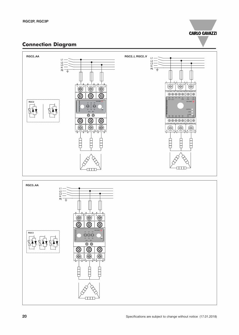
Connection Diagram
RGC2..AA RGC2..I, RGC2..V
RGC3..AA
L1L2L3NPE
A1 + A2-
1 L1 3 L2 5 L3
2 T1 4 T2 6 T3
Motor3 ~
*
L1L2L3NPE
A1 + A2-
1 L1 3 L2 5 L3
2 T1 4 T2 6 T3
Motor3 ~
*
L1L2L3NPE
A1 + A2-
1 L1 3 L2 5 L3
2 T1 4 T2 6 T3
RGC2
RGC3
Motor3 ~
*
L1L2L3NPE
A1 + A2-
1 L1 3 L2 5 L3
2 T1 4 T2 6 T3
RGC2
RGC3
Motor3 ~
*
L1L2L3NPE
A1 + A2-
1 L1 3 L2 5 L3
2 T1 4 T2 6 T3
Motor3 ~
*
L1L2L3NPE
A1 + A2-
1 L1 3 L2 5 L3
2 T1 4 T2 6 T3
Motor3 ~
*
L1L2L3NPE
A1 + A2-
1 L1 3 L2 5 L3
2 T1 4 T2 6 T3
Motor3 ~
*
L1L2L3NPE
A1 + A2-
1 L1 3 L2 5 L3
2 T1 4 T2 6 T3
Motor3 ~
*L1L2L3NPE
A1 + A2-
1 L1 3 L2 5 L3
2 T1 4 T2 6 T3
Motor3 ~
*
L1L2L3NPE
A1 + A2-
1 L1 3 L2 5 L3
2 T1 4 T2 6 T3
Motor3 ~
*
L1L2L3NPE
A1 + A2-
1 L1 3 L2 5 L3
2 T1 4 T2 6 T3
Motor3 ~
*
Specifications are subject to change without notice (17.01.2018) 21
RGC2P, RGC3P
Connection Diagram
Connection Configuration
Us- ~
C1 C2 11GND
ALARM
12NC
ALARM
14NO
ALARM
Us+ ~
Us- ~
C1 C2 11GND
ALARM
12NC
ALARM
14NO
ALARM
Us+ ~
Us- ~
C1 C2 11GND
ALARM
12NC
ALARM
14NO
ALARM
Us+ ~
Us- ~
C1 C2 11GND
ALARM
12NC
ALARM
14NO
ALARM
Us+ ~
Us- ~
C1 C2 11GND
ALARM
12NC
ALARM
14NO
ALARM
Us+ ~
Us- ~
C1 C2 11GND
ALARM
12NC
ALARM
14NO
ALARM
Us+ ~
CONTROL
LOAD
ALARM
GND4-20mA
12-20mA
0-20mAGND
4-20mA
12-20mA
0-20mA
CONTROL
LOAD
ALARM
CONTROL
LOAD
ALARM
CONTROL
LOAD
ALARM
CONTROL
LOAD
ALARM
CONTROL
LOAD
ALARM
RG S
olid
Sta
te C
ontr
olle
r
RG S
olid
Sta
te C
ontr
olle
rRG
Sol
id S
tate
Con
trol
ler
RG S
olid
Sta
te C
ontr
olle
r
RG S
olid
Sta
te C
ontr
olle
r
RG S
olid
Sta
te C
ontr
olle
r
A1GND
A24-20mA
A312-20mA
A40-20mA
A1GND
A21-5V
A30-5V
A40-10V
A5POT
A1GND
A21-5V
A30-5V
A40-10V
A5POT
A1GND
A1GND
A1GND
A24-20mA
A312-20mA
A40-20mA
24VDC/AC(+) (-)
24VDC/AC(+) (-)
24VDC/AC(+) (-)
24VDC/AC(+) (-)
GND(-) 5-10VDC
90-250VAC(~) (~)
90-250VAC(~) (~)
GND(-)
1-5VDC
0-5VDC
0-10VDC
GND(-)
1-5VDC
0-5VDC
0-10VDC
GND(-)
1-5VDC
0-5VDC
0-10VDC
A21-5V
A30-5V
A40-10V
A5POT
A21-5V
A30-5V
A40-10V
A5POT
0s 5s 0s 5s
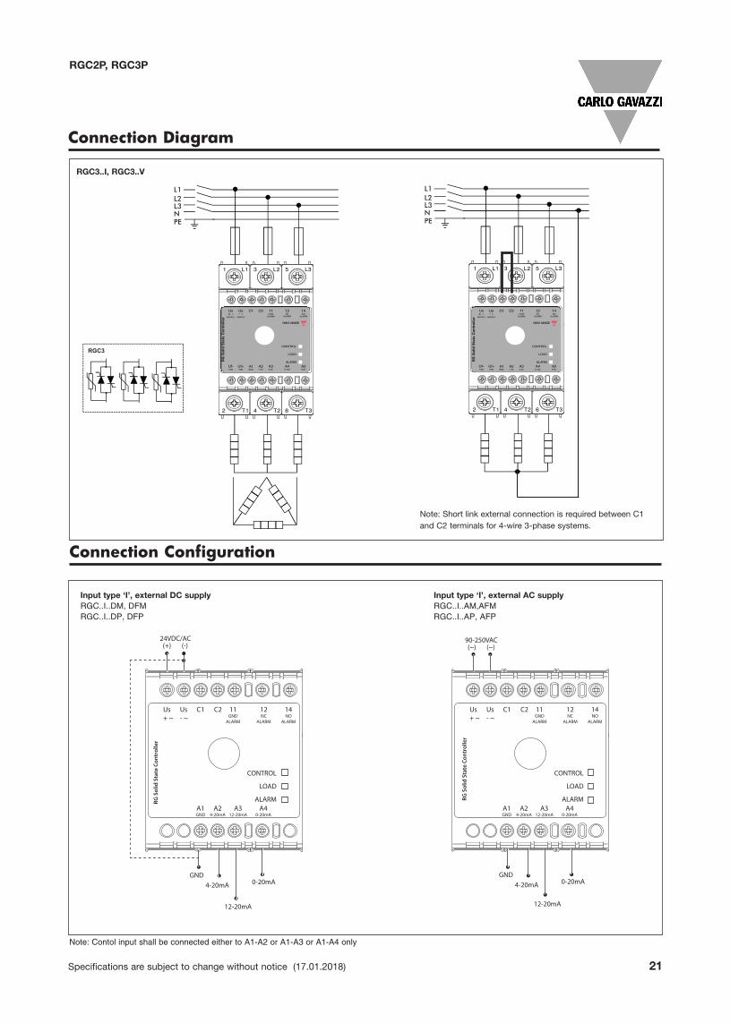
Input type ‘I’, external DC supply Input type ‘I’, external AC supplyRGC..I..DM, DFM RGC..I..AM,AFMRGC..I..DP, DFP RGC..I..AP, AFP
Note: Contol input shall be connected either to A1-A2 or A1-A3 or A1-A4 only
RGC3..I, RGC3..V
L1L2L3NPE
A1 + A2-
1 L1 3 L2 5 L3
2 T1 4 T2 6 T3
RGC2
RGC3
Motor3 ~
*
L1L2L3NPE
A1 + A2-
1 L1 3 L2 5 L3
2 T1 4 T2 6 T3
Motor3 ~
*
L1L2L3NPE
A1 + A2-
1 L1 3 L2 5 L3
2 T1 4 T2 6 T3
Motor3 ~
*
L1L2L3NPE
A1 + A2-
1 L1 3 L2 5 L3
2 T1 4 T2 6 T3
Motor3 ~
*
L1L2L3NPE
A1 + A2-
1 L1 3 L2 5 L3
2 T1 4 T2 6 T3
Motor3 ~
*
L1L2L3NPE
A1 + A2-
1 L1 3 L2 5 L3
2 T1 4 T2 6 T3
Motor3 ~
*
L1L2L3NPE
A1 + A2-
1 L1 3 L2 5 L3
2 T1 4 T2 6 T3
Motor3 ~
*
L1L2L3NPE
A1 + A2-
1 L1 3 L2 5 L3
2 T1 4 T2 6 T3
Motor3 ~
*
Note: Short link external connection is required between C1and C2 terminals for 4-wire 3-phase systems.

22 Specifications are subject to change without notice (17.01.2018)
RGC2P, RGC3P
Connection Configuration
Us- ~
C1 C2 11GND
ALARM
12NC
ALARM
14NO
ALARM
Us+ ~
Us- ~
C1 C2 11GND
ALARM
12NC
ALARM
14NO
ALARM
Us+ ~
Us- ~
C1 C2 11GND
ALARM
12NC
ALARM
14NO
ALARM
Us+ ~
Us- ~
C1 C2 11GND
ALARM
12NC
ALARM
14NO
ALARM
Us+ ~
Us- ~
C1 C2 11GND
ALARM
12NC
ALARM
14NO
ALARM
Us+ ~
Us- ~
C1 C2 11GND
ALARM
12NC
ALARM
14NO
ALARM
Us+ ~
CONTROL
LOAD
ALARM
GND4-20mA
12-20mA
0-20mAGND
4-20mA
12-20mA
0-20mA
CONTROL
LOAD
ALARM
CONTROL
LOAD
ALARM
CONTROL
LOAD
ALARM
CONTROL
LOAD
ALARM
CONTROL
LOAD
ALARM
RG S
olid
Sta
te C
ontr
olle
r
RG S
olid
Sta
te C
ontr
olle
rRG
Sol
id S
tate
Con
trol
ler
RG S
olid
Sta
te C
ontr
olle
r
RG S
olid
Sta
te C
ontr
olle
r
RG S
olid
Sta
te C
ontr
olle
r
A1GND
A24-20mA
A312-20mA
A40-20mA
A1GND
A21-5V
A30-5V
A40-10V
A5POT
A1GND
A21-5V
A30-5V
A40-10V
A5POT
A1GND
A1GND
A1GND
A24-20mA
A312-20mA
A40-20mA
24VDC/AC(+) (-)
24VDC/AC(+) (-)
24VDC/AC(+) (-)
24VDC/AC(+) (-)
GND(-) 5-10VDC
90-250VAC(~) (~)
90-250VAC(~) (~)
GND(-)
1-5VDC
0-5VDC
0-10VDC
GND(-)
1-5VDC
0-5VDC
0-10VDC
GND(-)
1-5VDC
0-5VDC
0-10VDC
A21-5V
A30-5V
A40-10V
A5POT
A21-5V
A30-5V
A40-10V
A5POT
0s 5s 0s 5s
Us- ~
C1 C2 11GND
ALARM
12NC
ALARM
14NO
ALARM
Us+ ~
Us- ~
C1 C2 11GND
ALARM
12NC
ALARM
14NO
ALARM
Us+ ~
Us- ~
C1 C2 11GND
ALARM
12NC
ALARM
14NO
ALARM
Us+ ~
Us- ~
C1 C2 11GND
ALARM
12NC
ALARM
14NO
ALARM
Us+ ~
Us- ~
C1 C2 11GND
ALARM
12NC
ALARM
14NO
ALARM
Us+ ~
Us- ~
C1 C2 11GND
ALARM
12NC
ALARM
14NO
ALARM
Us+ ~
CONTROL
LOAD
ALARM
GND4-20mA
12-20mA
0-20mAGND
4-20mA
12-20mA
0-20mA
CONTROL
LOAD
ALARM
CONTROL
LOAD
ALARM
CONTROL
LOAD
ALARM
CONTROL
LOAD
ALARM
CONTROL
LOAD
ALARM
RG S
olid
Sta
te C
ontr
olle
r
RG S
olid
Sta
te C
ontr
olle
rRG
Sol
id S
tate
Con
trol
ler
RG S
olid
Sta
te C
ontr
olle
r
RG S
olid
Sta
te C
ontr
olle
r
RG S
olid
Sta
te C
ontr
olle
r
A1GND
A24-20mA
A312-20mA
A40-20mA
A1GND
A21-5V
A30-5V
A40-10V
A5POT
A1GND
A21-5V
A30-5V
A40-10V
A5POT
A1GND
A1GND
A1GND
A24-20mA
A312-20mA
A40-20mA
24VDC/AC(+) (-)
24VDC/AC(+) (-)
24VDC/AC(+) (-)
24VDC/AC(+) (-)
GND(-) 5-10VDC
90-250VAC(~) (~)
90-250VAC(~) (~)
GND(-)
1-5VDC
0-5VDC
0-10VDC
GND(-)
1-5VDC
0-5VDC
0-10VDC
GND(-)
1-5VDC
0-5VDC
0-10VDC
A21-5V
A30-5V
A40-10V
A5POT
A21-5V
A30-5V
A40-10V
A5POT
0s 5s 0s 5s
Input type ‘V’, external DC supply Input type ‘V’, external AC supply
RGC..V..DM, DFM RGC..V..AM, AFM
RGC..V..DP, DFP RGC..V..AP, AFP
Input type ‘S’, external DC supply Input type ‘S16’, external DC supply
RGC..V..S RGC..V..S16
Note: Control input shall be connected either to A1-A2 or A1-A3 or A1-A4 or A1-A3-A5 in case an external potentiometer is used.
Note: Control input shall be connected to terminals A1-A4 in the case of the RGC3P..S.. In the case of the RGC3P..S16.., the control input shall be connectedto either A1-A2 or A1-A3 or A1-A4 or A1-A3-A5 in case an external potentiometer is used.
Specifications are subject to change without notice (17.01.2018) 23
RGC2P, RGC3P
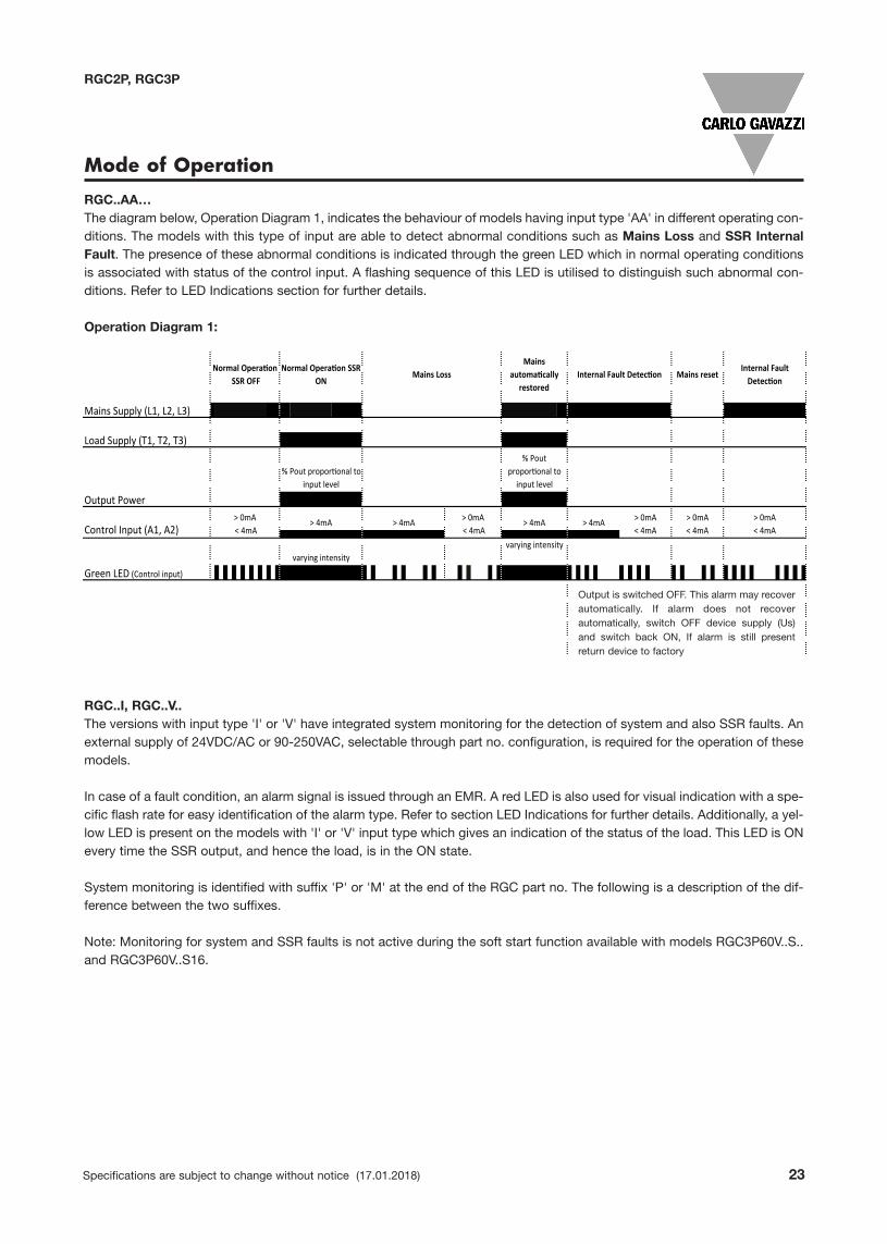
RGC..AA…The diagram below, Operation Diagram 1, indicates the behaviour of models having input type 'AA' in different operating con-ditions. The models with this type of input are able to detect abnormal conditions such as Mains Loss and SSR InternalFault. The presence of these abnormal conditions is indicated through the green LED which in normal operating conditionsis associated with status of the control input. A flashing sequence of this LED is utilised to distinguish such abnormal con-ditions. Refer to LED Indications section for further details.
Operation Diagram 1:
Mode of Operation
RGC..I, RGC..V..The versions with input type 'I' or 'V' have integrated system monitoring for the detection of system and also SSR faults. Anexternal supply of 24VDC/AC or 90-250VAC, selectable through part no. configuration, is required for the operation of thesemodels.
In case of a fault condition, an alarm signal is issued through an EMR. A red LED is also used for visual indication with a spe-cific flash rate for easy identification of the alarm type. Refer to section LED Indications for further details. Additionally, a yel-low LED is present on the models with 'I' or 'V' input type which gives an indication of the status of the load. This LED is ONevery time the SSR output, and hence the load, is in the ON state.
System monitoring is identified with suffix 'P' or 'M' at the end of the RGC part no. The following is a description of the dif-ference between the two suffixes.
Note: Monitoring for system and SSR faults is not active during the soft start function available with models RGC3P60V..S..and RGC3P60V..S16.
Mains Supply (L1, L2, L3)
Load Supply (T1, T2, T3)
Output Power
Green LED (Control input)
Mains reset
> 0mA< 4mA
Internal Fault
> 0mA< 4mA
> 0mA< 4mA
> 4mA
varying intensity
> 4mA> 4mA > 0mA < 4mA
% Pout to
input level
> 0mA < 4mA
varying intensity
% Pout to input level
> 4mAControl Input (A1, A2)
SSR ON
Mains
SSR OFF
Mains Internal Fault
Output is switched OFF. This alarm may recoverautomatically. If alarm does not recoverautomatically, switch OFF device supply (Us)and switch back ON, If alarm is still presentreturn device to factory
24 Specifications are subject to change without notice (17.01.2018)
RGC2P, RGC3P
1. RGC..I..P, RGC..V..PThe versions with suffix 'P' are available only with switching mode 'E', i.e., phase angle. The detectable alarm conditions inthis series are the following:-� Mains Loss (Operation Diagram 2)-� SSR Over Temperature (Operation Diagram 3)-� SSR Internal Fault (Operation Diagram 3)
The following operation diagrams show the behaviour of the RGC..I..P and RGC..V..P under different operating and abnor-mal conditions.
Operation Diagram 2:
Operation Diagram 3:
Mode of Operation
Mains Supply (L1, L2, L3)
Load Supply (T1, T2, T3)
Load Current
Supply Voltage (Us)
Control Input (A1 - A2/A3/A4/A5)
Green LED (Control & Supply)
Yellow LED (Load status)
Red LED (Alarm LED)
Alarm Output, NO (11-14)
Alarm Output, NC (11-12)
Mains Su l (L1, L2, L3
Load Su l (T1, T2, T3
Load Curren
Su l Volta e (Us)
Control In ut (A1 - A2/A3/A4/A5)
Green LED (Control & Supply)
Yellow LED (Load status)
Red LED (Alarm LED)
Alarm Out ut, NO (11-14
Alarm Out ut, NC (11-12
% Pout to input level
Mains Loss >1s
Mains restored
Alarm is cleared if mains is restored and present
for >1s
Alarm is issued in case mains loss is present >1s
Over temperature
% Pout to input level
% Pout prop. to input level
Us Loss
Us
resetOver temperature
% Pout to
input level
% Pout to
input level
SSR OFF
SSR
ON
SSR ON
1s
Mains Su l (L1, L2, L3
Load Su l (T1, T2, T3
Load Curren
Su l Volta e (Us)
Control In ut (A1 - A2/A3/A4/A5)
Green LED (Control & Supply)
Yellow LED (Load status)
Red LED (Alarm LED)
Alarm Out ut, NO (11-14
Alarm Out ut, NC (11-12
Mains Supply (L1, L2, L3)
Load Supply (T1, T2, T3)
Load Current
Supply Voltage (Us)
Control Input (A1 - A2/A3/A4/A5)
Green LED (Control & Supply)
Yellow LED (Load status)
Red LED (Alarm LED)
Alarm Output, NO (11-14)
Alarm Output, NC (11-12)
% Pout to input level
Mains Loss >1s
Mains restored
Alarm is cleared if mains is restored and present
for >1s
Alarm is issued in case mains loss is present >1s
Over temperature
% Pout to input level
% Pout prop. to input level
Us Loss
Us
resetOver temperature
% Pout to
input level
% Pout to
input level
SSR OFF
SSR
ON
SSR ON
1s
Specifications are subject to change without notice (17.01.2018) 25
RGC2P, RGC3P
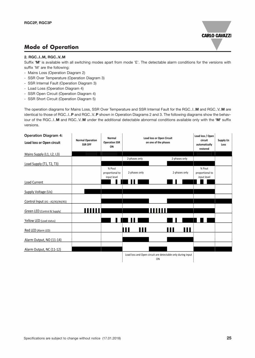
2. RGC..I..M, RGC..V..MSuffix 'M' is available with all switching modes apart from mode 'E'. The detectable alarm conditions for the versions withsuffix 'M' are the following:-� Mains Loss (Operation Diagram 2)-� SSR Over Temperature (Operation Diagram 3)-� SSR Internal Fault (Operation Diagram 3)-� Load Loss (Operation Diagram 4)-� SSR Open Circuit (Operation Diagram 4)-� SSR Short Circuit (Operation Diagram 5)
The operation diagrams for Mains Loss, SSR Over Temperature and SSR Internal Fault for the RGC..I..M and RGC..V..M areidentical to those of RGC..I..P and RGC..V..P shown in Operation Diagrams 2 and 3. The following diagrams show the behav-iour of the RGC..I..M and RGC..V..M under the additional detectable abnormal conditions available only with the 'M' suffixversions.
Operation Diagram 4:
Mode of Operation
Load loss or Open circuit
Mains Supply (L1, L2, L3)2 phases only 2 phases only
Load Supply (T1, T2, T3)
Load Current
Supply Voltage (Us)
Control Input (A1 A2/A3/A4/A5)
Green LED (Control & Supply)
Yellow LED (Load status)
Red LED (Alarm LED)
Alarm Output, NO (11 14)
Alarm Output, NC (11 12)Load loss and Open circuit are detectable only during input
ON
Supply UsLoss
Normal OperationSSR OFF
NormalOperation SSR
ON
Load loss / Opencircuit
automaticallyrestored
Load loss or Open Circuiton one of the phases
2 phases only 2 phases only% Pout
proportional toinput level
% Poutproportional toinput level

26 Specifications are subject to change without notice (17.01.2018)
RGC2P, RGC3P
Operation diagram 5
Mode of Operation
Mains Supply (L1, L2, L3)
Load Supply (T1, T2, T3)
Load Current
Supply Voltage (Us)
Control Input (A1 - A2/A3/A4/A5)
Green LED (Control & Supply)
Yellow LED (Load status)
Red LED (Alarm LED)
Alarm Output, NO (11-14)
Alarm Output, NC (11-12)
Normal
n SSR OFF
Normal
SR ON
SSR short circuit during control OFF
Fan operation for RGC..F..
START
FAN: ON
Is Chip temperature >
115°C ?
N
Y
Chip temperature <
85°C ?
N
YSSR output: OFFRed LED: ONAlarm Signal: ON
Y
N
FAN: OFF
Chip temperature
limit reached?
START
FAN: ON
Is Chip temperature >
70 °C ?
N
Y
Is Chip temperature <
60°C ?
N
YSSR output: OFFRed LED: ONAlarm Signal: ON
Y
N
Y
N
SSR output: ONRed LED: OFFAlarm Signal: OFF
FAN: OFF
Is Chip temperature <
80°C?
Chip temperature
limit reached?
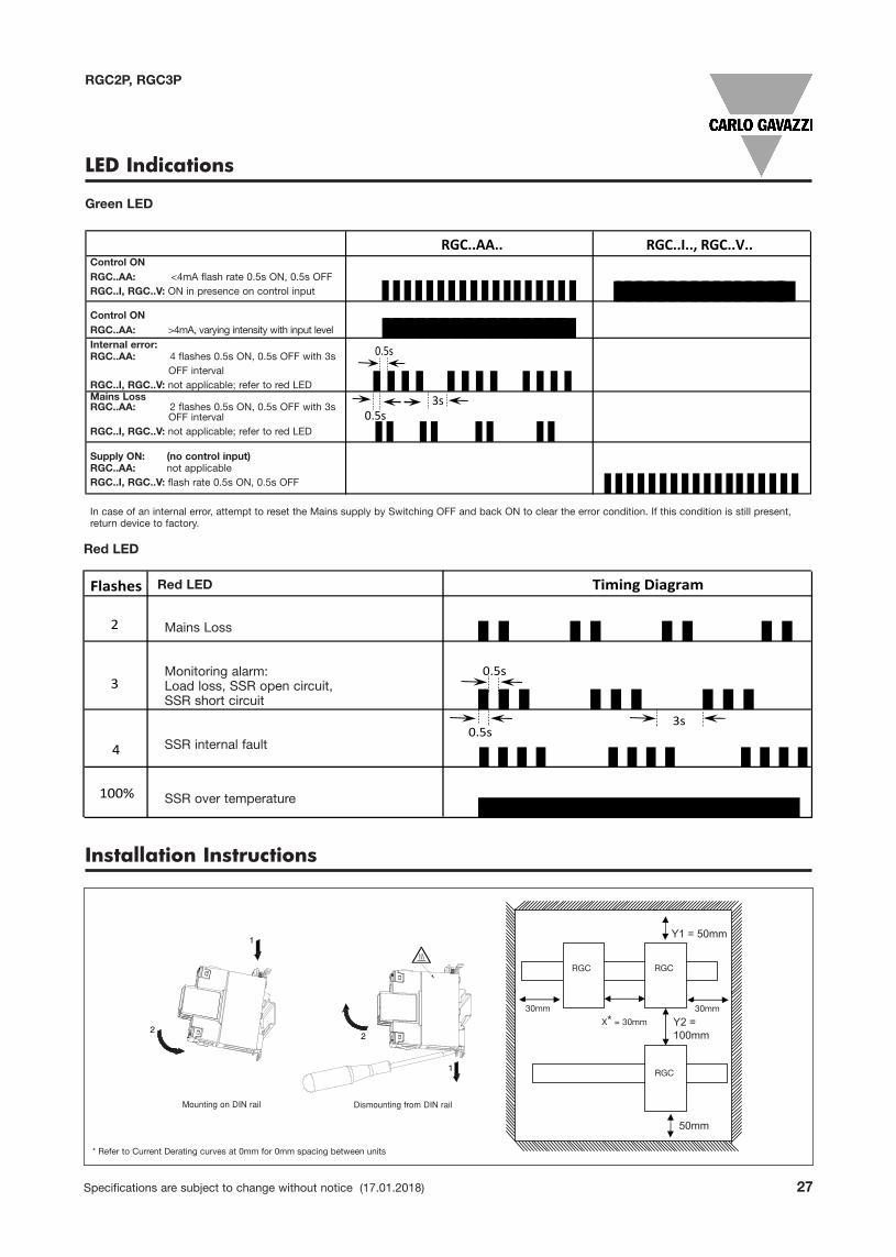
Control ONRGC..AA: <4mA flash rate 0.5s ON, 0.5s OFFRGC..I, RGC..V: ON in presence on control input
Control ONRGC..AA: >4mA, varying intensity with input levelInternal error:RGC..AA: 4 flashes 0.5s ON, 0.5s OFF with 3s
OFF intervalRGC..I, RGC..V: not applicable; refer to red LEDMains LossRGC..AA: 2 flashes 0.5s ON, 0.5s OFF with 3s
OFF intervalRGC..I, RGC..V: not applicable; refer to red LED
Supply ON: (no control input)RGC..AA: not applicableRGC..I, RGC..V: flash rate 0.5s ON, 0.5s OFF
In case of an internal error, attempt to reset the Mains supply by Switching OFF and back ON to clear the error condition. If this condition is still present,return device to factory.
Specifications are subject to change without notice (17.01.2018) 27
RGC2P, RGC3P
Green LED
Red LED
Installation Instructions
Y2 =100mm
Y1 = 50mm
50mm
X = 20mm20mm20mm
Mounting on DIN rail Dismounting from DIN rail
LED Indications
Flashes Fault
100%
4
3
2
0.5s
0.5s3s
RGC..AA.. RGC..I.., RGC..V..
0.5s
3s0.5s
Mains Loss
Monitoring alarm:Load loss, SSR open circuit, SSR short circuit
SSR internal fault
SSR over temperature
30mm
X* = 30mm
* Refer to Current Derating curves at 0mm for 0mm spacing between units
30mm
Red LED
RGC RGC
RGC
28 Specifications are subject to change without notice (17.01.2018)
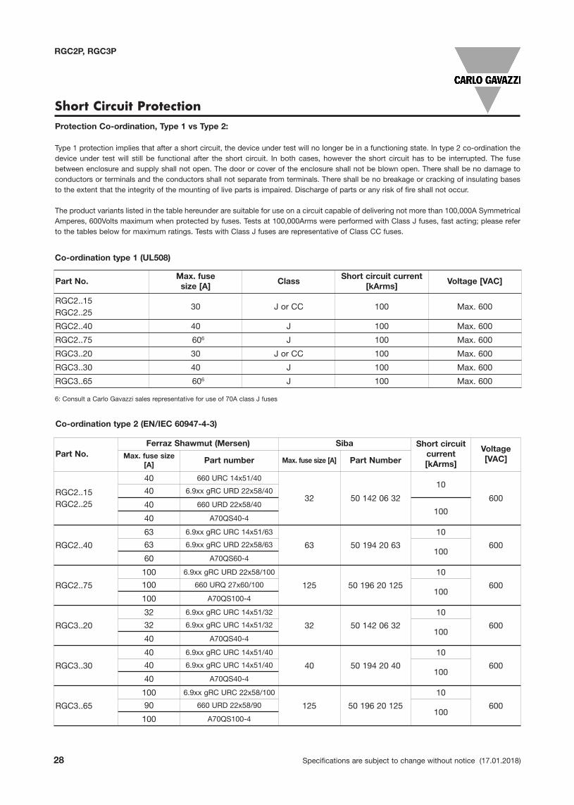
RGC2P, RGC3P
Co-ordination type 2 (EN/IEC 60947-4-3)
Part No.Ferraz Shawmut (Mersen) Siba Short circuit
current[kArms]
Voltage[VAC]Max. fuse size
[A] Part number Max. fuse size [A] Part Number
RGC2..15RGC2..25
40 660 URC 14x51/40
32 50 142 06 32
10
60040 6.9xx gRC URD 22x58/40
40 660 URD 22x58/40100
40 A70QS40-4
RGC2..40
63 6.9xx gRC URC 14x51/63
63 50 194 20 63
10
60063 6.9xx gRC URD 22x58/63100
60 A70QS60-4
RGC2..75
100 6.9xx gRC URD 22x58/100
125 50 196 20 125
10
600100 660 URQ 27x60/100100
100 A70QS100-4
RGC3..20
32 6.9xx gRC URC 14x51/32
32 50 142 06 32
10
60032 6.9xx gRC URC 14x51/32100
40 A70QS40-4
RGC3..30
40 6.9xx gRC URC 14x51/40
40 50 194 20 40
10
60040 6.9xx gRC URC 14x51/40100
40 A70QS40-4
RGC3..65
100 6.9xx gRC URC 22x58/100
125 50 196 20 125
10
60090 660 URD 22x58/90100
100 A70QS100-4
6: Consult a Carlo Gavazzi sales representative for use of 70A class J fuses
Short Circuit Protection
Part No.Max. fusesize [A]
ClassShort circuit current
[kArms]Voltage [VAC]
RGC2..15RGC2..25
30 J or CC 100 Max. 600
RGC2..40 40 J 100 Max. 600
RGC2..75 606 J 100 Max. 600
RGC3..20 30 J or CC 100 Max. 600
RGC3..30 40 J 100 Max. 600
RGC3..65 606 J 100 Max. 600
Co-ordination type 1 (UL508)
Protection Co-ordination, Type 1 vs Type 2:
Type 1 protection implies that after a short circuit, the device under test will no longer be in a functioning state. In type 2 co-ordination thedevice under test will still be functional after the short circuit. In both cases, however the short circuit has to be interrupted. The fusebetween enclosure and supply shall not open. The door or cover of the enclosure shall not be blown open. There shall be no damage toconductors or terminals and the conductors shall not separate from terminals. There shall be no breakage or cracking of insulating basesto the extent that the integrity of the mounting of live parts is impaired. Discharge of parts or any risk of fire shall not occur.
The product variants listed in the table hereunder are suitable for use on a circuit capable of delivering not more than 100,000A SymmetricalAmperes, 600Volts maximum when protected by fuses. Tests at 100,000Arms were performed with Class J fuses, fast acting; please referto the tables below for maximum ratings. Tests with Class J fuses are representative of Class CC fuses.

Specifications are subject to change without notice (17.01.2018) 29
RGC2P, RGC3P
Type 2 Protection Coordination with Miniature Circuit Breakers (M.C.Bs)
7: Between MCB and Load (including return path which goes back to the mains if applicable)
Note: A prospective current of 6kArms and a 230/400V power supply system is assumed for the above suggestedspecifications. For cables with different cross section than those mentioned above please consult Carlo Gavazzi's TechnicalSupport Group.
Solid State Relay ABB Model no. for ABB Model no. for Wire cross Minimum length of
type Z - type M. C. B. B - type M. C. B. sectional area [mm2] Cu wire conductor [m]7
(rated current) (rated current)
RGC2..15 S201 - Z10 (10A) S201 - B4 (4A) 1.0 7.6RGC2..25 1.5 11.4RGC3..20 2.5 19.0
(1,800 A2s) S201 - Z16 (16A) S201 - B6 (6A) 1.0 5.2 1.5 7.8 2.5 13.0 4.0 20.8
S201 - Z20 (20A) S201 - B10 (10A) 1.5 12.6 2.5 21.0
S201 - Z25 (25A) S201 - B13 (13A) 2.5 25.0 4.0 40.0
RGC2..40 S201 - Z20 (20A) S201 - B10 (10A) 1.5 4.2RGC3..30 2.5 7.0 4.0 11.2(6,600 A2s) S201 - Z32 (32A) S201 - B16 (16A) 2.5 13 4.0 20.8 6.0 31.2 RGC2..75 S201 - Z25 (25A) S201 - B16 (16A) 2.5 3.1RGC3..65 4.0 5.0 6.0 7.5(15,000 A2s) S201 - Z50 (50A) S201 - B25 (25A) 4.0 8.0 6.0 12.0 10.0 20.0 16.0 32.0
S201 - Z63 (63A) S201 - B32 (32A) 6.0 11.3 10.0 18.8 16.0 30.0
Accessories
Fan
Ordering Key
Fan accessoryfor RGC2..75 and RGC3..65
RGC3FAN60
30 Specifications are subject to change without notice (17.01.2018)
RGC2P, RGC3PRG...P19
Specifications are subject to change without notice (20.02.2017) 13
25
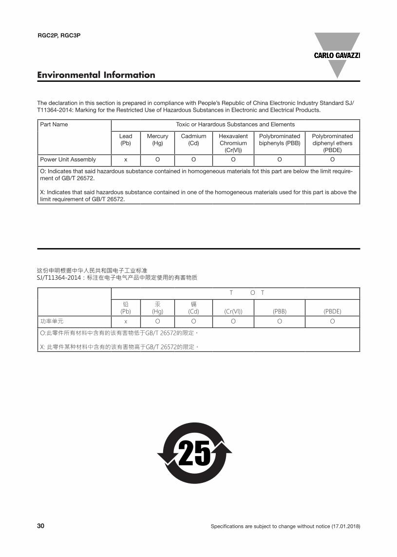
The declaration in this section is prepared in compliance with People’s Republic of China Electronic Industry Standard SJ/T11364-2014: Marking for the Restricted Use of Hazardous Substances in Electronic and Electrical Products.
Part Name Toxic or Harardous Substances and Elements
Lead(Pb)
Mercury(Hg)
Cadmium(Cd)
Hexavalent Chromium
(Cr(Vl))
Polybrominated biphenyls (PBB)
Polybrominated diphenyl ethers
(PBDE)
Power Unit Assembly x O O O O O
O: Indicates that said hazardous substance contained in homogeneous materials fot this part are below the limit require-ment of GB/T 26572.
X: Indicates that said hazardous substance contained in one of the homogeneous materials used for this part is above the limit requirement of GB/T 26572.
Environmental Information
(Pb) (Hg) (Cd) (Cr(Vl)) (PBB) (PBDE)
x O O O O O