Solid-state overload relay Relais de surcharge ...kgrp.in/pdfs/simens/3RB12.pdf · Elektronisches...
19
Elektronisches Überlastrelais 3RB12 Solid-state overload relay Relais de surcharge electronique Relé electronico di sobrecarga Relè elettronico di sovraccarica Elektroniska överlastrelä Betriebsanleitung Instructions Bestell-Nr./Order No.: 3ZX1012-0RB12-1AA1 Ausgabe/Edition 01/2003 GWA 4NEB 631 2282-30a Kanchan Eneterprises Ph.no.-2533 3226 / 4766 Email id- [email protected]
-
Upload
phungkhuong -
Category
Documents
-
view
221 -
download
0
Transcript of Solid-state overload relay Relais de surcharge ...kgrp.in/pdfs/simens/3RB12.pdf · Elektronisches...

Elektronisches Überlastrelais 3RB12Solid-state overload relay Relais de surcharge electronique Relé electronico di sobrecarga Relè elettronico di sovraccarica Elektroniska överlastrelä
BetriebsanleitungInstructions
Bestell-Nr./Order No.: 3ZX1012-0RB12-1AA1Ausgabe/Edition 01/2003
GWA 4NEB 631 2282-30a
Kanch
an E
neter
prise
s
Ph.no.-
2533
3226
/ 476
6
Email id
- e@
kanc
hana
nand
.com
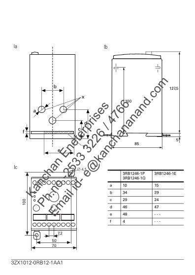
3RB1246-1P3RB1246-1Q
3RB1246-1E
a 10 15
b 34 29
c 29 24
d 46 47
e 48 - - -
f 4 - - -
100
7050
∅ 4,5
7,2
Ic
85
127,5
5
100
IbIa
b
e
a
f cd
x
y
Kanch
an E
neter
prise
s
Ph.no.-
2533
3226
/ 476
6
Email id
- e@
kanc
hana
nand
.com
3ZX1012-0RB12-1AA1

3RB1253-0F
3RB1257-0K
3RB1262-0L
a 120 145 230
b 85 85 85
c 155 175 190
d 110 105 120
e 40 50 70
f ∅ 7 ∅ 9 ∅ 11
g 42 52 70
h 37 48 - - -
i 125 130 135
j 41 46 55
k 20 30 40
l 131 151 166
m 7,2 7,2 7,2
n 13 - - - - - -
o 145 160 175
i d b
ag
eh
k m
f
o
IIb
IIa
lj
n
c
Kanch
an E
neter
prise
s
Ph.no.-
2533
3226
/ 476
6
Email id
- e@
kanc
hana
nand
.com
3ZX1012-0RB12-1AA1
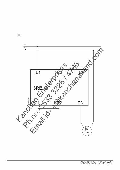
III
M1~
NSB00302a
L1 L2 L3
T1 T2 T3
LN
3RB12
3ZX1012-0RB12-1AA1
Kanch
an E
neter
prise
s
Ph.no.-
2533
3226
/ 476
6
Email id
- e@
kanc
hana
nand
.com

H 2
F2 F3 F4
A1
A2
K1E1 3 5
642
1 3 5L1 L2 L3
A2 A1
F5
F1
T1 T2 T3
642
U WV
CLASS
97
S1A
95
9896
K1ES1E
Test/Reset
K1 Overload
K2 Ground Fault
Y1Y2
Z1
Z2
5, 10, 15, 20, 25, 30
GroundFault
H 1 H 3
05 07
06 08
Ready GroundFault
Overload
C2T2/C1
Y1Y2
Automatic-Reset
Remote-Reset
ϑ
Y1Y2T1
ϑ
T2/C1
3UL22
3 RB 12
⇑
⇑
K1E
L1L2L3N
M3 ~
IV
3RB12
3ZX1012-0RB12-1AA1
Kanch
an E
neter
prise
s
Ph.no.-
2533
3226
/ 476
6
Email id
- e@
kanc
hana
nand
.com

V 3RB12..-...03RB12..-...2
2530
40
50
6070 80
90100
5
10
1520 25
30
Class
Test/Reset
G/9401 3RB1246-1EM00
95 96 97 98 08070605
A1 Y1 Y2A2 T1 T2/C1 C2
Overload
Gnd Fault
Ready
ResetGnd FaultAC 220-240V J - -
3RB12
NC Overload NO NC Gnd Fault NO
A
A B
3ZX1012-0RB12-1AA1
Kanch
an E
neter
prise
s
Ph.no.-
2533
3226
/ 476
6
Email id
- e@
kanc
hana
nand
.com
2530
40
50
6070 80
90100
5
10
1520 25
30
Class
Test/Reset
G/9401 3RB1246-1EM00
95 96 97 98 08070605
A1 Y1 Y2A2 T1 T2/C1 C2
Overload
Gnd Fault
Ready
ResetGnd FaultAC 220-240V ϑ ↑ ↑
3RB12
NC NO NC NO
A
A B
Tripped OVL-Warning
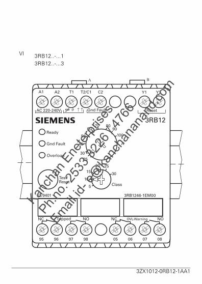
3RB12..-...13RB12..-...3
VI
3ZX1012-0RB12-1AA1
Kanch
an E
neter
prise
s
Ph.no.-
2533
3226
/ 476
6
Email id
- e@
kanc
hana
nand
.com
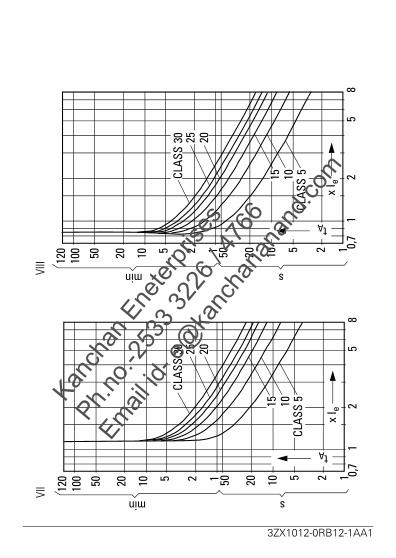
VIII
VII
x I e
tA125102050
12
58
0,7
125102050100
120
smin15 10 5
CLAS
SCLAS
S30 25 20
x I e
125102050
12
58
0,7
125102050100
120
smin
15 10 5CL
ASS
tA
CLAS
S30 25 20
3ZX1012-0RB12-1AA1
Kanch
an E
neter
prise
s
Ph.no.-
2533
3226
/ 476
6
Email id
- e@
kanc
hana
nand
.com

Device description
En
glish
Limited touch protection
Degree of protection in conformity with IEC 60529: IP 20 for devices 70 mmIP 00 for devices > 70 mmShock-proof in conformity with DIN VDE 0106, Part 100.Installation and maintenance by technical personnel only. Follow the operating instruction!
1 Device description
The 3RB12 electronic overload relay protects electrical equipment, such as three-phase AC motors and trans-formers, with three different protection mechanisms.
Overload protection
The 3RB12 compares the motor current actuallyflowing with the set current and evaluates the values in a microprocessor.
Thermistor protection
PTC thermistors in the motor windings sense the motor temperature. If the thermistor responds, the relay trips.
Earth-fault protection
Versions with internal earth-fault detection are suitable for service in three-wire systems.Versions with earth-fault detection by means of an external summation current transformer are suitable for service in three-wire and four-wire systems.
WARNING
HAZARDOUS VOLTAGE
CAN CAUSE ELECTRICAL SHOCK
AND BURNS.
DISCONNECT POWER BEFORE PROCEEDING
WITH ANY WORK ON THIS EQUIPMENT.
Kanch
an E
neter
prise
s
Ph.no.-
2533
3226
/ 476
6
Email id
- e@
kanc
hana
nand
.com
3ZX1012-0RB12-1AA1 11
Installation
En
glis
h
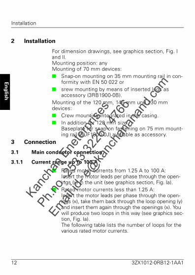
2 Installation
For dimension drawings, see graphics section, Fig. I and II.Mounting position: anyMounting of 70 mm devices: Snap-on mounting on 35 mm mounting rail in con-
formity with EN 50 022 or srew mounting by means of inserted lugs as
accessory (3RB1900-0B).Mounting of the 120 mm, 145 mm und 230 mm devices: Crew mounting integrated in the casing. In addition for 120 mm size:
Baseplate for snap-on fastening on 75 mm mount-ing rail (3UF1900-0J) available as accessory.
3 Connection
3.1 Main conductor connection
3.1.1 Current range up to 100 A
Rated motor currents from 1.25 A to 100 A:Insert the motor leads per phase through the open-ings (x) in the unit (see graphics section, Fig. Ia).
Rated motor currents less than 1.25 A:Insert the motor leads per phase through the open-ings (x), take them back through the loop opening (y) and insert them again through the openings (x). You will produce two loops in this way (see graphics sec-tion, Fig. Ia). The following table lists the number of loops for the various rated motor currents.
Kanch
an E
neter
prise
s
Ph.no.-
2533
3226
/ 476
6
Email id
- e@
kanc
hana
nand
.com
12 3ZX1012-0RB12-1AA1

Connection
En
glish
The device setting current Ie calculated according to:Ie = n x IN
Example IN = 0.5 A; n = 3; Ie = 1.5 A
Protection of single-phase motors
If single-phase AC motors are to be protected by the 3RB12 solid-state overload relay, phase L must be looped through the device. The main circuits must be connected as shown in Fig. III.
Note
This is only possible if the device has no internal earth fault detection:3RB12 46- ...0., -...1.3RB12 53- ...0., -...1.3RB12 57- ...0., -...1.3RB12 62- ...0., -...1.
Number of loops n 5 4 3 2
Rated motor current IN [A] 0.25 to 0.3
0.31 to 0.41
0.42 to 0.62
0.63 to 1.24
Kanch
an E
neter
prise
s
Ph.no.-
2533
3226
/ 476
6
Email id
- e@
kanc
hana
nand
.com
3ZX1012-0RB12-1AA1 13

Connection
En
glis
h
3.1.2 Current range 50 A to 820 A
Busbar connection: see graphics section, Fig. II
3.2 Auxiliary conductor connection
Thermistor sensor
A link (A) is in place when the device is delivered. This link must be removed when the sensor is connected (see illustration in Fig. V and VI).
3.3 Connection scheme
See graphics section of Fig. IV for circuit diagram,showing Automatic resets and remote resets.Facility for connecting summation current transformer 3UL22 for external earth fault monitoring.
Finely stranded conductor with cable lug [mm2]
Stranded con-ductor with cable lug [mm2]
Connection screws
Tightening torque
[Nm/lb.in]
Tagtermination
[mm x mm]3RB1253 35 to 95 50 to 120 M8 10 to 14 /
89 to 24 20 x 4
3RB1257 50 to 240 70 to 240 M10 14 to 24 /124 to 210
30 x 6
3RB1262 50 to 240 185 to 240 M 10(Connec-
tion to con-tactor 3TF68)
14 to 24 /124 to 210
40 x 8
M 12 (Con-nection to contactor
3TF69)
20 to 35 /177 to 310
Solid
[mm2]
Finely stranded with/ without end sleeve [mm2]
AWG Connecting screws
[mm]
Tightening torque
[Nm/lb.in]1x(0.5 to 4) 2x(0.5 to 2.5)
1x(0.5 to 2.5) 2x(0.5 to 1.5)
20 to 14 0.8x4...5.5Pozidriv 2
0.8 to 1.2/ 7 to 11Kan
chan
Ene
terpr
ises
Ph.no.-
2533
3226
/ 476
6
Email id
- e@
kanc
hana
nand
.com
14 3ZX1012-0RB12-1AA1
Operation
En
glish
4 Operation
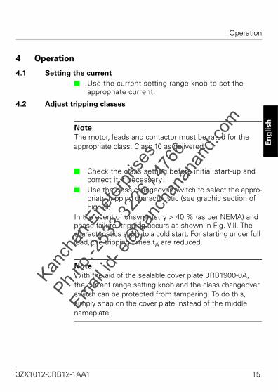
4.1 Setting the current
Use the current setting range knob to set the appropriate current.
4.2 Adjust tripping classes
Note
The motor, leads and contactor must be rated for the appropriate class. Class 10 as delivered.
Check the class setting before initial start-up and correct it if necessary!
Use the class changeover switch to select the appro-priate tripping characteristic (see graphic section of Fig. VII).
In the event of unsymmetry > 40 % (as per NEMA) and phase failure, tripping occurs as shown in Fig. VIII. The characteristics apply to a cold start. For starting under full load, the tripping times tA are reduced.
Note
With the aid of the sealable cover plate 3RB1900-0A, the current range setting knob and the class changeover switch can be protected from tampering. To do this, simply snap on the cover plate instead of the middle nameplate.
Kanch
an E
neter
prise
s
Ph.no.-
2533
3226
/ 476
6
Email id
- e@
kanc
hana
nand
.com
3ZX1012-0RB12-1AA1 15
Operation
En
glis
h
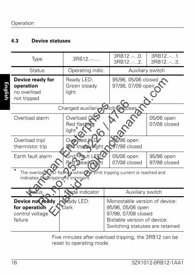
4.3 Device statuses
Five minutes after overload tripping, the 3RB12 can be reset to operating mode.
Type 3RB12..-..... 3RB12..-...0.3RB12..-...2.
3RB12..-...1.3RB12..-...3.
Status Operating indic. Auxiliary switch
Device ready for
operation
no overloadnot tripped
Ready LED: Green steady light
95/96, 05/06 closed97/98, 07/08 open
Changed auxiliary switch statuses
Overload alarm Overload LED: Red flashing light*
05/06 open07/08 closed
Overload trip/thermistor trip
Overload LED:Red steady light
95/96 open97/98 closed
Earth fault alarm Gnd. Fault LED:Red steady light
05/06 open07/08 closed
95/96 open97/98 closed
* The overload LED flashes when the limit tripping current is reached and indicates that tripping is imminent.
Status Mode indicator Auxiliary switch
Device not ready
for operation
control voltage failure
Ready LED: Dark
Monostable version of device:95/96, 05/06 open97/98, 07/08 closedBistable version of device: Switching statuses are retained
Kanch
an E
neter
prise
s
Ph.no.-
2533
3226
/ 476
6
Email id
- e@
kanc
hana
nand
.com
16 3ZX1012-0RB12-1AA1

Operation
En
glish
4.4 Test
Statuses after the Test/Reset button has been pressed:
Test Status Withoutmain current
Withmain current*
button O.k. Faulty O.k. Faulty
Press forup to 2 s
LED Ready
LED Gen. Fault
LED Overload
Status of auxiliary switching elements unchanged
Press forafter 2 s
LED Ready
LED Gen. Fault
LED Overload
Status of auxiliary switching elements
un-changed
Reset** un-changed
Reset**
Press for> 5 s
LED Ready
LED Gen. Fault
LED Overload
Status of auxiliary switching elements Reset
LED lights up LED flashes LED flickers LED dark
* Unless current is detected in all three phases, the device behaves as listed in the "Without main circuit current“ column.
**Status of auxiliary switching elements "Reset": 95/96, 05/06 open, 97/98, 07/08 closed.
Kanch
an E
neter
prise
s
Ph.no.-
2533
3226
/ 476
6
Email id
- e@
kanc
hana
nand
.com
3ZX1012-0RB12-1AA1 17
Operation
En
glis
h
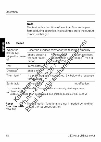
Note
The test with a test time of less than 5 s can be per-formed during operation. In a fault-free state the outputs remain unchanged.
4.5 Reset
Reset function with free trip
The protection functions are not impeded by holding down the test/reset button.
When the 3RB12 hastripped because of
Reset the overload relay after the following times by
briefly pressing the test / reset button
Remote reset (briefly press but-ton at Y1-Y2)
automatic-reset (bridge** Y1-Y2)
Test immediately
Overload* after 5 min
Thermistor* If the temperature has reached 5 K below the response temperature
Earth fault immediately not effective* If thermistor- and overload has tripped simultaneously, the longer reset
phase applies.** Bridge (B) is fixed to Y1 as delivered (see graphics section of Fig. V and VI).
Kanch
an E
neter
prise
s
Ph.no.-
2533
3226
/ 476
6
Email id
- e@
kanc
hana
nand
.com
18 3ZX1012-0RB12-1AA1

Technical data
En
glish
5 Technical data
Specifications DIN VDE 0660 Part 102 / IEC 60947-4-1, DIN VDE 0660 Part 200 / IEC 60947-5-1,UL 508, CSA C 22.2
EMC Pulse packets (burst), IEC 61000-4-4 2 kVDischarge of static electricity, IEC 61000-4-2 8 kVRadiated high-frequency fields, IEC 61000-4-3 3 V/mSurge voltage, IEC 61000-4-5 2 kV
Weight 70 mm: 0.6 kg 145 mm: 1.9 kg120 mm: 1.0 kg 230 mm: 3.2 kg
Rated control supply voltage
Working range:AC 0.85 to 1.1 x Us; 2 VA 24 V DC: 0.85 to 1.2 x Us (DIN 19 240); 2W
Main circuit Frequency 50/60 HzRated insulation voltage Ui 1000 V
3RB1246 690 VPermissible ambient temperature -25 to +70 °CStorage: -40 to +80 °CTripping limit values with three-polesymmetrical overload:Tripping current 110...120% x Ie Tripping time < 20 min
Auxiliary circuit
Contacts 2 x (1 NO and 1 NC) Electrical isolation of the auxiliary switch (potential-free)
IEC: Rated insulation voltage Ui 300 VSwitching capacity:AC-15: 6A/24V; 6A/120V; 3A/230VDC-13: 2A/24V; 0.55A/60V; 0.25A/125V
UL/CSA: B300, R300
Kanch
an E
neter
prise
s
Ph.no.-
2533
3226
/ 476
6
Email id
- e@
kanc
hana
nand
.com
3ZX1012-0RB12-1AA1 19

Technical data
En
glis
h
Short-circuit protection
Main circuitShort-circuit protection with fuses for motor feeders with short-circuit currents up to 50 kA at 690 V, 50/60 Hz (see data given in catalog)Control circuitFuse links, duty class gL/gG 6 A
quick-acting 10 AProtective circuit-breaker 1.6 A
C characteristic
Thermistor protection
Thermistor sensor in the motor is connected to terminals T1/T2Total cold resistance Rcold 1.5 kΩMeasuring circuit loading ≤ 5 mW
(at Rcold = 1.5 kΩ) Voltage at sensor circuit ≤ 2 V (at Rcold = 1.5 kΩ) Response value 2.7 to 3.1 kΩReturn value 1.5 to 1.65 kΩ
Earth fault protection
The following information based on sinusoidal faultcurrents of 50/60 Hz:externalSummation current transformers 3UL220.-.A are con-nected to terminal C1/C2. The pick-up delay is 200 ms ≤ t ≤ 500 ms.internalWith a motor current between 0.3 and 2 times the set current, the device trips in the event of an earth-fault cur-rent of 30% of the set current. With a motor current between 2 and 8 times the set cur-rent, the device trips in the event of an earth-fault current of 15% of the set current.The pick-up delay is 0.5 to 1 seconds.
Kanch
an E
neter
prise
s
Ph.no.-
2533
3226
/ 476
6
Email id
- e@
kanc
hana
nand
.com
20 3ZX1012-0RB12-1AA1
Description de l'appareil
Fra
nça
is
Protection partielle contre les contacts directs
Degré de protection selon CEI 60529: IP 20 pour relais de largeur 70 mmIP 00 pour relais de largeur > 70 mmProtégé contre l'accès avec un doigt selon DIN VDE 0106, partie 100Mise en service et maintenance uniquement par des per-sonnes qualifiées. Respectez les instructions de service!
1 Description de l'appareil
Le relais électronique de surcharge 3RB12 dispose de différents mécanismes de protection pour les matériels électriques tels que moteurs triphasés et transforma-teurs.
Protection contre les surcharges
Le 3RB12 compare le courant momentané du moteur avec le courant de réglage du relais et traite les valeurs dans un microprocesseur.
Protection de moteurs par thermistance
Les sondes à thermistance CTP placées dans les en-roulements du moteur assurent la mesure de la tempé-rature de ce dernier. Lors du dépassement d'un seuil, le relais provoque le déclenchement.
Protection contre les défauts à la terre
Appareils avec reconnaissance interne de défauts à la terre pour réseaux 3 conducteurs.Appareils avec reconnaissance de défauts à la terre par transformateur sommateur externe pour réseaux á 3 ou 4 conducteurs.
Attention !
Tension dangereuse !
Risque d’électrocution et de brûlure.
Isoler cet appareil du réseau avant d’y
intervenir pour travaux.
Kanch
an E
neter
prise
s
Ph.no.-
2533
3226
/ 476
6
Email id
- e@
kanc
hana
nand
.com
3ZX1012-0RB12-1AA1 21