Solid Shape Pro 10
71
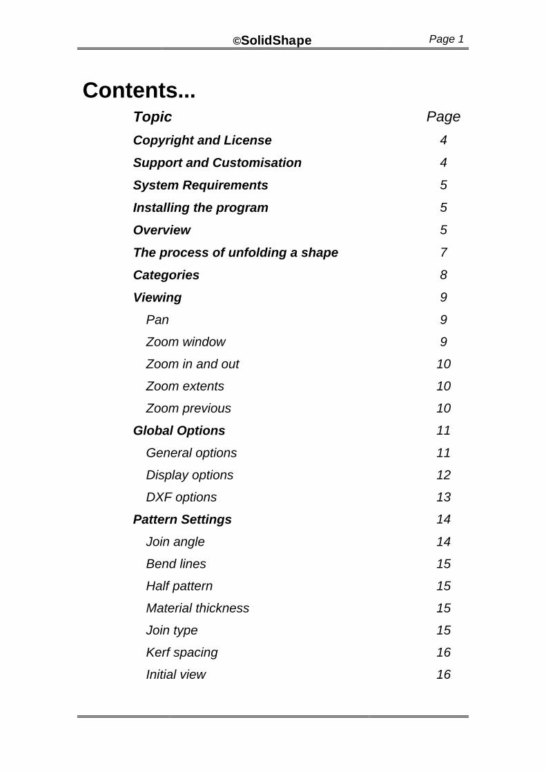
©SolidShape Page 1 Contents... Topic Page Copyright and License 4 Support and Customisation 4 System Requirements 5 Installing the program 5 Overview 5 The process of unfolding a shape 7 Categories 8 Viewing 9 Pan 9 Zoom window 9 Zoom in and out 10 Zoom extents 10 Zoom previous 10 Global Options 11 General options 11 Display options 12 DXF options 13 Pattern Settings 14 Join angle 14 Bend lines 15 Half pattern 15 Material thickness 15 Join type 15 Kerf spacing 16 Initial view 16
-
Upload
lukman-tarigan-sumatra -
Category
Documents
-
view
326 -
download
7
description
Solid Shape Introduction
Transcript of Solid Shape Pro 10
©SolidShape Page 1
Contents... Topic Page
Copyright and License 4
Support and Customisation 4
System Requirements 5
Installing the program 5
Overview 5
The process of unfolding a shape 7
Categories 8
Viewing 9
Pan 9
Zoom window 9
Zoom in and out 10
Zoom extents 10
Zoom previous 10
Global Options 11
General options 11
Display options 12
DXF options 13
Pattern Settings 14
Join angle 14
Bend lines 15
Half pattern 15
Material thickness 15
Join type 15
Kerf spacing 16
Initial view 16
©SolidShape Page 2
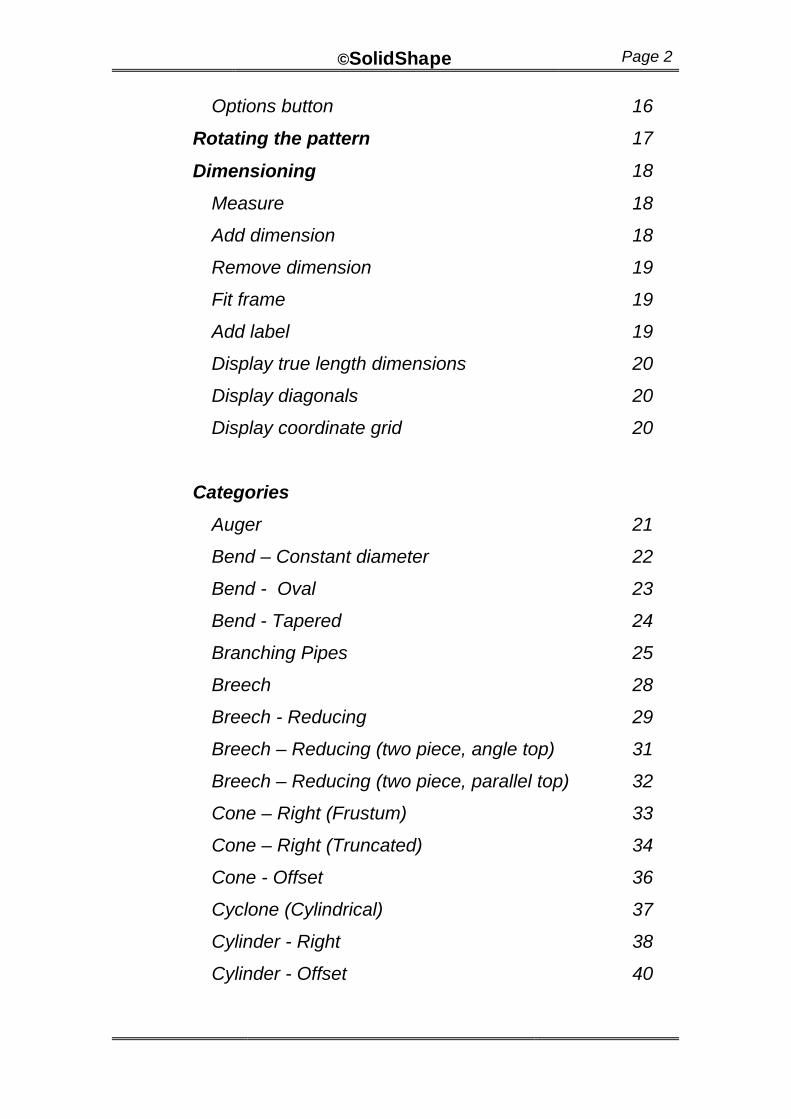
Options button 16
Rotating the pattern 17
Dimensioning 18
Measure 18
Add dimension 18
Remove dimension 19
Fit frame 19
Add label 19
Display true length dimensions 20
Display diagonals 20
Display coordinate grid 20
Categories
Auger 21
Bend – Constant diameter 22
Bend - Oval 23
Bend - Tapered 24
Branching Pipes 25
Breech 28
Breech - Reducing 29
Breech – Reducing (two piece, angle top) 31
Breech – Reducing (two piece, parallel top) 32
Cone – Right (Frustum) 33
Cone – Right (Truncated) 34
Cone - Offset 36
Cyclone (Cylindrical) 37
Cylinder - Right 38
Cylinder - Offset 40
©SolidShape Page 3
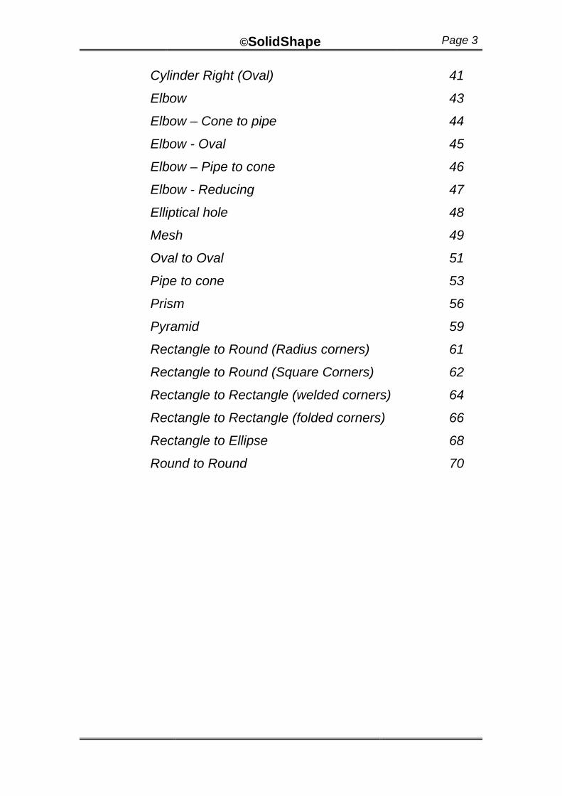
Cylinder Right (Oval) 41
Elbow 43
Elbow – Cone to pipe 44
Elbow - Oval 45
Elbow – Pipe to cone 46
Elbow - Reducing 47
Elliptical hole 48
Mesh 49
Oval to Oval 51
Pipe to cone 53
Prism 56
Pyramid 59
Rectangle to Round (Radius corners) 61
Rectangle to Round (Square Corners) 62
Rectangle to Rectangle (welded corners) 64
Rectangle to Rectangle (folded corners) 66
Rectangle to Ellipse 68
Round to Round 70
©SolidShape Page 4
Copyright Notice
This manual is the copyright of R & L CAD Services Pty Ltd. Apart from any fair dealing for the purposes private study, research, criticism or review as permitted under the Copyright Act, no part may be either copied or transmitted in any form, by any means, be it electronic, mechanical, recording or otherwise, without the written prior consent of.
The software is the copyright of Richard Stewart, Marian, Queensland, Australia.
License agreement
License conditions are displayed during the installation of the software. If you do not agree with the terms of the license you should not proceed with the installation..
Disclaimer
Every attempt has been made to produce a program that is functional, easy to use and accurate. The final checking of the developed shape remains your responsibility. R & L CAD Services Pty Ltd accepts no responsibility for any losses arising from the use of the program.
A summary of the License conditions and disclaimer is available when you are running the software by selecting the “Disclaimer” item from the Help menu
Support
Direct software support may be obtained from R & L CAD Services Pty Ltd by telephone, fax or email.
Ongoing Development
R & L CAD Services Pty Ltd is dedicated to product improvement. Please let us know if you encounter difficulties in using the program or manual or have suggestions for improvements and additions.
©SolidShape Page 5
Customisation
If you have a special shape not included in the standard package, we are happy to discuss a customised version for a negotiated fee. If the proposed customisation happens to be in line with our plans for developing and improving the product, this cost may be minimal.
System requirements.
SolidShape requires a system capable of running Microsoft Windows (Windows 95, 98, NT 4 and Windows 2000). Approximately 10 Mb of hard disk space is required to load SolidShape.
While not essential, a CAD program is useful to:
?? quickly and easily produce copies of the resultant shape
?? mirror the development to create right and left hand versions
?? incorporate the development into other drawings for further detailing and dimensioning
?? check the accuracy of the marking out or of the finished product by measuring diagonals and other distances on the screen comparing them to the plate.
?? reduce time and material wastage by manipulating the shapes on screen to obtain the best fit on the plate
?? Plotting to scale to produce full size paper templates.
Installing on your computer
Separate instructions are supplied for installing the program on your computer. These will have been supplied with the original packaging or on the www.plate-n-sheet.com web site. If you require additional instructions please call or email.
©SolidShape Page 6
Overview
SolidShape is a software program designed to unfold shapes commonly encountered by fabricators and sheet metal workers. The dimensions and other parameters that define the shape are entered by the user and may be any reasonable value. These may be altered at any time and the appearance shape will change dynamically.
The shape may be viewed as either a 3D model or as a flat pattern at any stage of the process. Tools are supplied to zoom in or out to see the shape in detail. If it is being viewed as a model, several viewing angles (top, front, side, end and four isometric angles) are available at the click of a button and true length measurements may be taken from the model.
Where possible, error messages will let you know if a parameter is not valid for the shape being created.
Several dimensioning modes are available and the resultant pattern may be printed or exported as a DXF for use in other software.

©SolidShape Page 7
The process of unfolding a shape
1 Start the program and click the “New” button and select a category by clicking on one of the shape images.
2 This will display a Model Window and a diagram of the shape with spaces for entering the dimensions. Use the left and right pointer buttons to scroll through the choices until you find the one that is the best match for the information.
3 Enter the values that define the shape.
4 View the 3D model by clicking any of the view buttons. If the model is not visible or partly off the screen click the “Zoom Extents”.
5 When you are satisfied with the appearance of the model click the “Develop Pattern” button to view the pattern. You may alternate between model view and pattern view as you wish.
6 Add dimensions if required. There are several different methods available, displayed in the “Dimension” pull down menu.
7 Print the image to your Windows System printer or export a DXF file for use in a CAD program or profile cutter.
©SolidShape Page 8
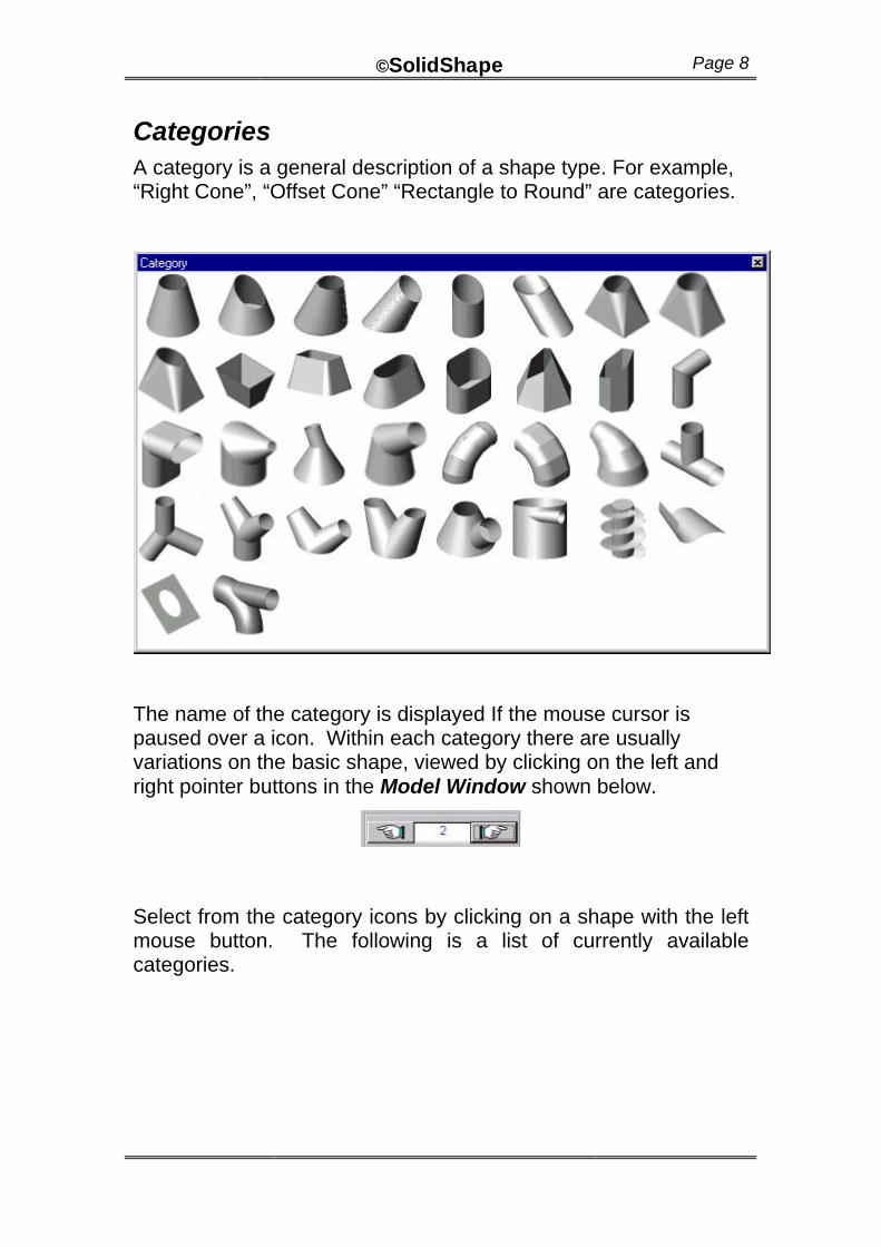
Categories A category is a general description of a shape type. For example, “Right Cone”, “Offset Cone” “Rectangle to Round” are categories.
The name of the category is displayed If the mouse cursor is paused over a icon. Within each category there are usually variations on the basic shape, viewed by clicking on the left and right pointer buttons in the Model Window shown below.
Select from the category icons by clicking on a shape with the left mouse button. The following is a list of currently available categories.

©SolidShape Page 9
Viewing
The view functions may be accessed by the toolbar buttons along the top of the screen, via “View “ pull down menu, or by clicking the right mouse button over the image. The following options are available to assist in viewing the model or pattern:
Pan
Zoom Window
Zoom In
Zoom Out
Zoom Extents
Zoom Previous.
Pan
Use “Pan” when you wish to center the image on the screen. Pan moves the field of view without changing the magnification. While the model or pattern appears to move on the screen, it is important to realize that the field of view is all that is changing and that the coordinates of any point on the model do not change.
Zoom Window
Use when you wish to magnify a part of the model or pattern to get a closer look at it. Pick the diagonal corners of a box or window around the area you wish to examine. Note: After picking the first corner with the left mouse button, hold the button down and release it when the window is the correct size. The area inside the window is enlarged to fill the screen. A message is disolayed when the limits of magnification are at the maximum.
©SolidShape Page 10
Zoom In
Use when you want a closer look at the image on the screen. For example if the image is too small, use zoom in to enlarge the image on the screen. As with other display functions, it is important to realize that only the image is getting larger, measured distances and dimensions on the shape do not change. It is similar in principle to viewing an object through a magnifying glass.
Zoom Out
Use when you wish to make the image appear smaller on the screen. See also Zoom In.
Zoom Extents
Use when you wish to zoom the image so that it is as large as possible while still fitting all of the image onto the screen.
Zoom Previous
Return to the previous zoom or panned state. You may “zoom previous” repeatedly until you eventually return to the first view of the item.
©SolidShape Page 11
Global Options
The Global Options dialog controls the default settings and display of the shape. The available options are grouped using the three tabs: General, Display and DXF.
The settings in Global Options affect all developments in the current session. These options may be saved as the default startup options by clicking the “Save” button. Otherwise they apply only to the current session.
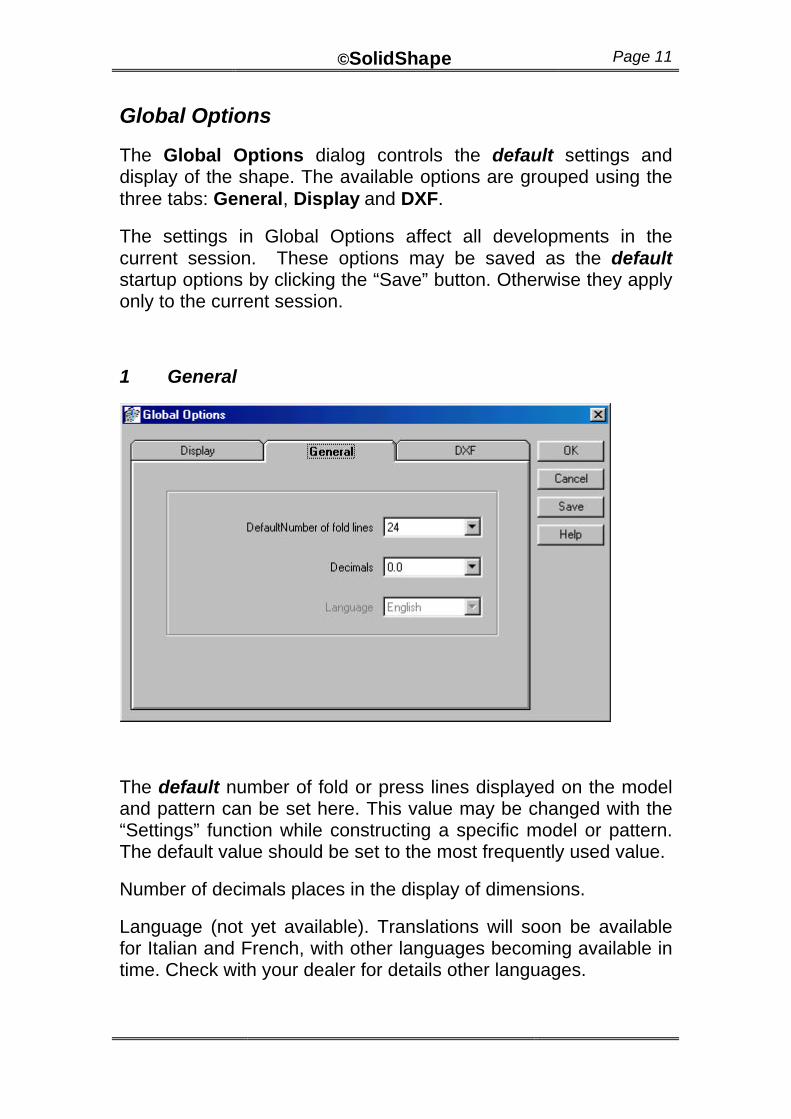
1 General
The default number of fold or press lines displayed on the model and pattern can be set here. This value may be changed with the “Settings” function while constructing a specific model or pattern. The default value should be set to the most frequently used value.
Number of decimals places in the display of dimensions.
Language (not yet available). Translations will soon be available for Italian and French, with other languages becoming available in time. Check with your dealer for details other languages.
©SolidShape Page 12
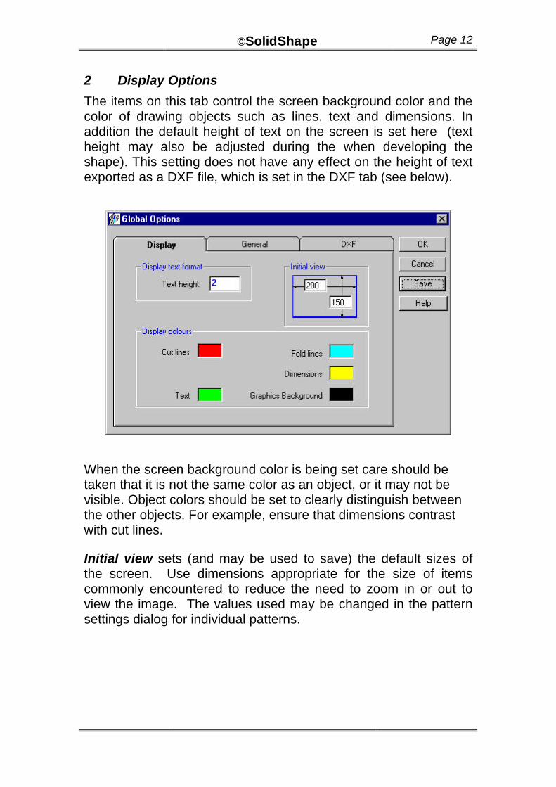
2 Display Options
The items on this tab control the screen background color and the color of drawing objects such as lines, text and dimensions. In addition the default height of text on the screen is set here (text height may also be adjusted during the when developing the shape). This setting does not have any effect on the height of text exported as a DXF file, which is set in the DXF tab (see below).
When the screen background color is being set care should be taken that it is not the same color as an object, or it may not be visible. Object colors should be set to clearly distinguish between the other objects. For example, ensure that dimensions contrast with cut lines.
Initial view sets (and may be used to save) the default sizes of the screen. Use dimensions appropriate for the size of items commonly encountered to reduce the need to zoom in or out to view the image. The values used may be changed in the pattern settings dialog for individual patterns.
©SolidShape Page 13
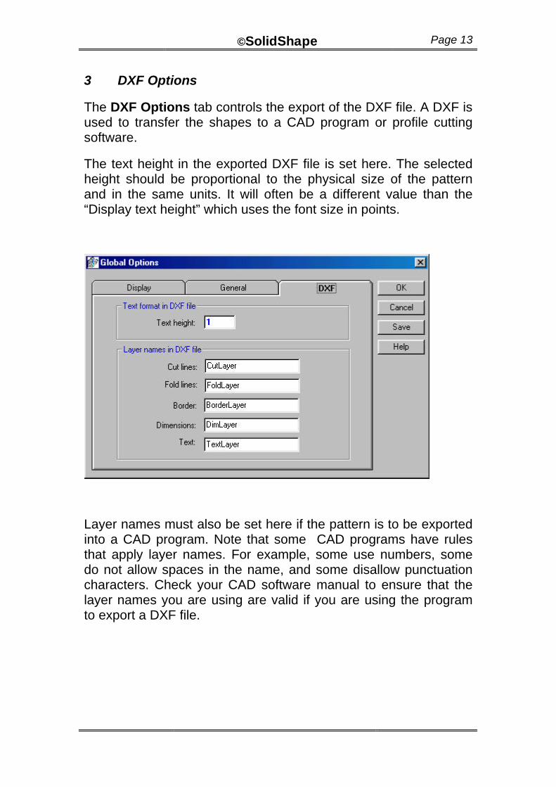
3 DXF Options
The DXF Options tab controls the export of the DXF file. A DXF is used to transfer the shapes to a CAD program or profile cutting software.
The text height in the exported DXF file is set here. The selected height should be proportional to the physical size of the pattern and in the same units. It will often be a different value than the “Display text height” which uses the font size in points.
Layer names must also be set here if the pattern is to be exported into a CAD program. Note that some CAD programs have rules that apply layer names. For example, some use numbers, some do not allow spaces in the name, and some disallow punctuation characters. Check your CAD software manual to ensure that the layer names you are using are valid if you are using the program to export a DXF file.
©SolidShape Page 14
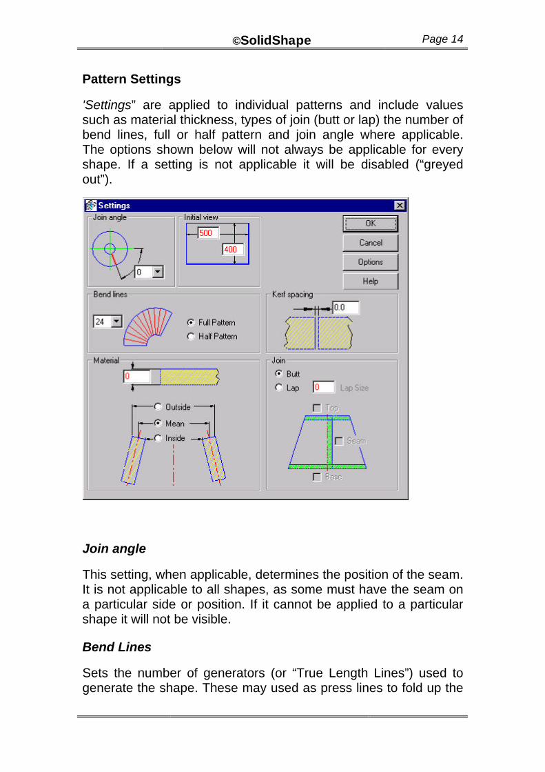
Pattern Settings
'Settings” are applied to individual patterns and include values such as material thickness, types of join (butt or lap) the number of bend lines, full or half pattern and join angle where applicable. The options shown below will not always be applicable for every shape. If a setting is not applicable it will be disabled (“greyed out”).
Join angle
This setting, when applicable, determines the position of the seam. It is not applicable to all shapes, as some must have the seam on a particular side or position. If it cannot be applied to a particular shape it will not be visible.
Bend Lines
Sets the number of generators (or “True Length Lines”) used to generate the shape. These may used as press lines to fold up the
©SolidShape Page 15
shape. Generally speaking, a greater number of bend lines results in a more accurate pattern, particularly for transitional shapes (for example Square to Round). However, a large number of lines may also slow down the generation of the views and pattern. The default value of 24 is sufficient for most shapes based on the cone and cylinder. It may need to be increased for shapes such as the mesh development.
Half Pattern / Full Pattern
A half pattern may be created for those shapes that are symmetrical. If it is not symmetrical, care should be taken that both of the pattern halves have been produced.
Material thickness
Set the thickness of the material here. The unit used must be the same as that used for the other sizes. That is, if the length, diameter, height, etc are entered in millimeters, meters or inches, the thickness value must be in the same unit.
After setting the thickness value, the program must be told whether the dimensions being used are inside dimensions, outside dimensions or mean dimensions. This is so that the thickness compensation, when applicable, may be applied in the correct direction.
Join type
The type of join may be either:
A “butt join”, where the edges of the material butt up against each other with no overlap. This is commonly used with larger plate sizes.
OR
A “lap join”, where the material overlaps by a set amount at the join. An allowance for overlap may also be set at the top and base of most patterns. The options will be “grayed” out when a lap may not be used.
Care must be taken when applying an overlap allowance to right cones and offset cones when the top radius is close to the apex of the cone. In these cases a top lap may extend past the apex of the
©SolidShape Page 16
cone and will not be valid. This is usually obvious in either the pattern view or wire-frame view.
Kerf Spacing This applies when multiple parts are nested in a single sheet (for example, the elbow). In such cases this option will be visible and allows the user to set a gap between each component to allow for the thickness of the cut.
Initial View
Sets the size of the screen. Use dimensions appropriate for the size of items commonly encountered to reduce the need to zoom in or out to view the image. The default values of this setting may be set in the Global Settings dialog.
Options button
Clicking on this button runs the Global Options dialog. For more details see Global Options.
Note
All the above settings are specific to the pattern being developed. For example, if you are working on more than one pattern at a time and set “Thickness” to 3, this value is applied only to the current pattern and other patterns that are currently open may have a different thickness value applied to them.
©SolidShape Page 17
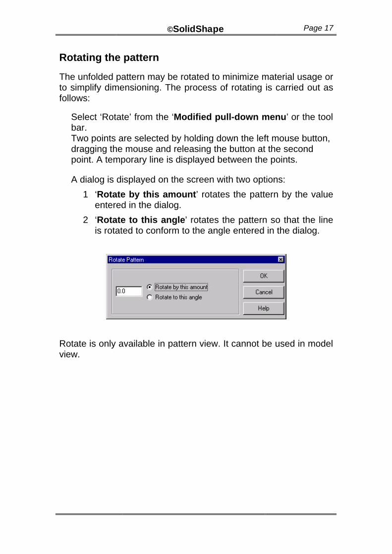
Rotating the pattern
The unfolded pattern may be rotated to minimize material usage or to simplify dimensioning. The process of rotating is carried out as follows:
Select ‘Rotate’ from the ‘Modified pull-down menu’ or the tool bar. Two points are selected by holding down the left mouse button, dragging the mouse and releasing the button at the second point. A temporary line is displayed between the points.
A dialog is displayed on the screen with two options:
1 ‘Rotate by this amount’ rotates the pattern by the value entered in the dialog.
2 ‘Rotate to this angle’ rotates the pattern so that the line is rotated to conform to the angle entered in the dialog.
Rotate is only available in pattern view. It cannot be used in model view.
©SolidShape Page 18
Dimensioning
There are several methods of obtaining dimensional data from the pattern and model. The following topics describe these methods, which are activated by selecting from the "Dimension” pull down menu. In some cases a button is available on the toolbar for ease of use.
Measure
Measurements may be taken between points on the model or pattern to find distances and angles. A distance is measured by pressing the left mouse button close to a point. Drag the mouse and release the button close to another point. The measured distance is displayed on the screen, along with the coordinates of each point and the angle formed by the line of measurement.
The measurement will be taken from the points on the model or pattern closest to where the mouse is pressed or released. If you wish to identify the coordinates of a single point, simply press and release the mouse button over a single point.
Note: Measurements may be taken on both the model and the pattern. The dimension feature may only be applied to the pattern.
Add Dimension
Adding a manual dimension is similar to ‘Measure’ described above, however a dimension is displayed on the pattern and may be printed out. Dimensions may be added to the pattern but not the model.
The dimension updates automatically as the parameters of the shape change. Dimensions may be removed using the Remove Dimension option on the toolbar or on the dimension menu.
The dimension text height may be changed using the slider control on each parameter dialog. The default height of the dimension text may set in the Global Options dialogue (‘Display’ tab).
©SolidShape Page 19
Remove Dimension
Manual dimensions may be removed using the ‘Remove Dimension’ button on the toolbar or the dimension pull-down menu. Left click the mouse close to the dimension text. Where several dimensions are close to each other, the dimension with the mid-point nearest the cursor is the one removed.
Dimensions may be removed one at a time. You must click the toolbar button each time. Alternatively, ALL dimensions may be removed simultaneously by selecting this item from the ‘Dimension’ menu.
Fit Frame
A rectangular frame is drawn around the extents of the pattern. The length, width and area of the frame is displayed on its boundary and is a useful tool for estimating. The Fit Frame option is found on the toolbar and on the ‘Dimension pull down menu.
“Fit Frame” is available only in pattern view, not the model view. Changes to the shape automatically update the frame.
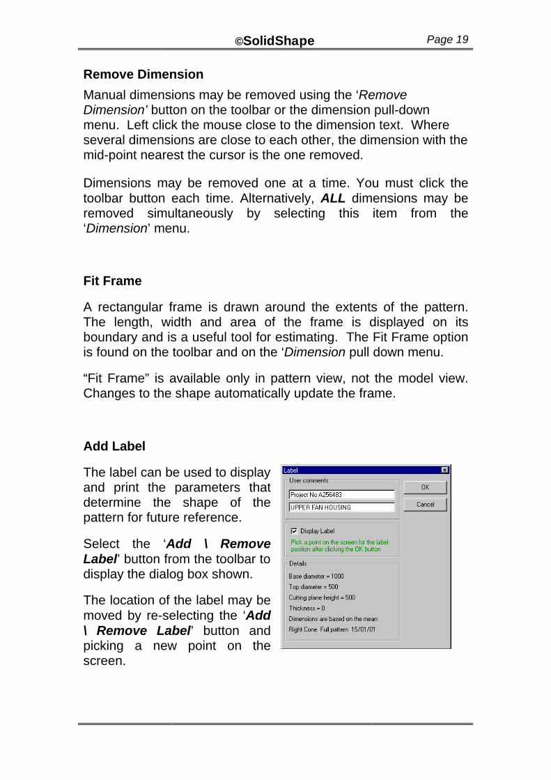
Add Label
The label can be used to display and print the parameters that determine the shape of the pattern for future reference.
Select the ‘Add \ Remove Label’ button from the toolbar to display the dialog box shown.
The location of the label may be moved by re-selecting the ‘Add \ Remove Label’ button and picking a new point on the screen.
©SolidShape Page 20
True Length Dimensions
This feature will print the true length distance along each bend line and around the top and base of the pattern.
Diagonals
This feature draws a dashed line diagonally between each point on the pattern and writes the length along the line similar to the true length distance. This may be useful for stepping off the pattern or for checking the accuracy of the pattern after it is transferred to the material.
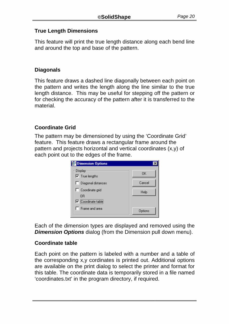
Coordinate Grid
The pattern may be dimensioned by using the ‘Coordinate Grid’ feature. This feature draws a rectangular frame around the pattern and projects horizontal and vertical coordinates (x,y) of each point out to the edges of the frame.
Each of the dimension types are displayed and removed using the Dimension Options dialog (from the Dimension pull down menu).
Coordinate table
Each point on the pattern is labeled with a number and a table of the corresponding x,y cordinates is printed out. Additional options are available on the print dialog to select the printer and format for this table. The coordinate data is temporarily stored in a file named ‘coordinates.txt’ in the program directory, if required.
©SolidShape Page 21
Auger
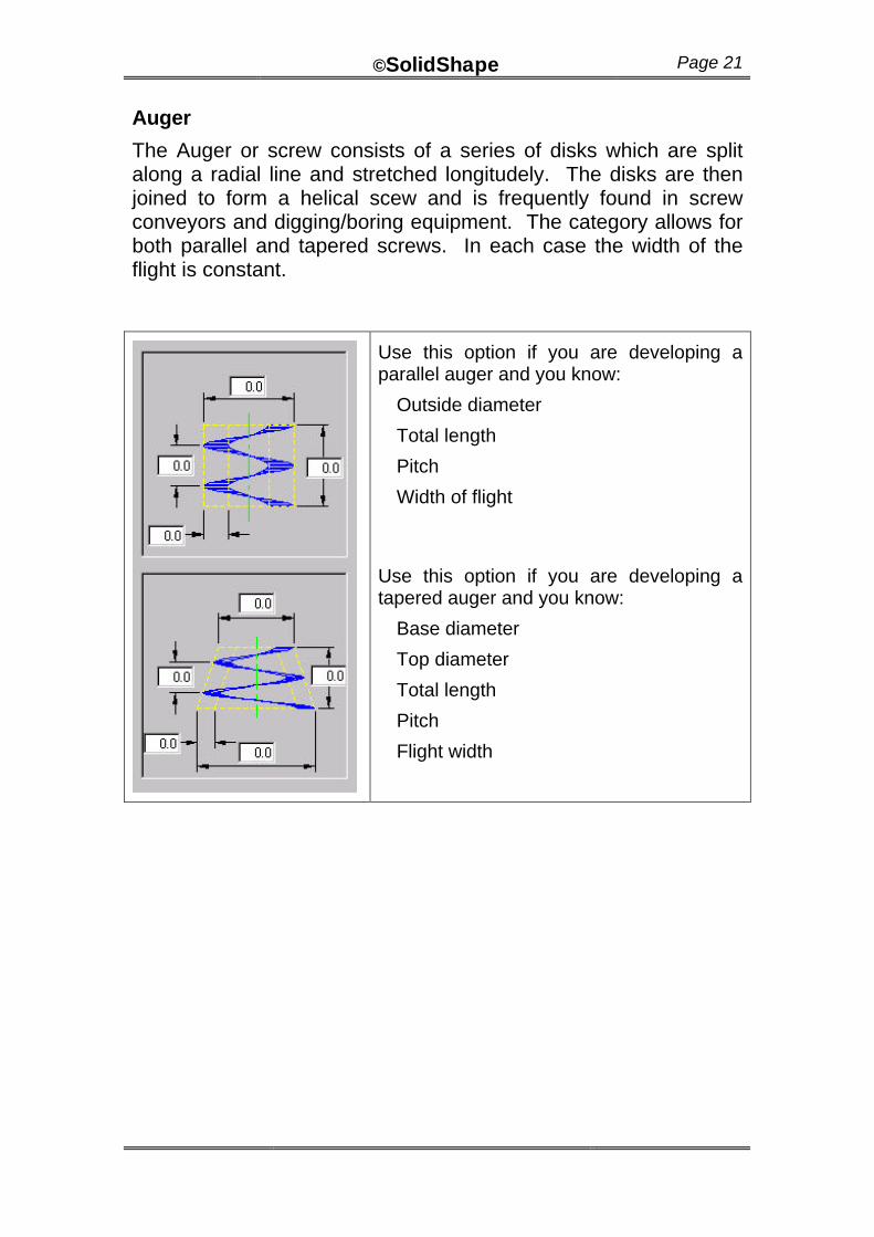
The Auger or screw consists of a series of disks which are split along a radial line and stretched longitudely. The disks are then joined to form a helical scew and is frequently found in screw conveyors and digging/boring equipment. The category allows for both parallel and tapered screws. In each case the width of the flight is constant.
Use this option if you are developing a parallel auger and you know:
Outside diameter
Total length
Pitch
Width of flight
Use this option if you are developing a tapered auger and you know:
Base diameter
Top diameter
Total length
Pitch
Flight width
©SolidShape Page 22
Bend – Constant Diameter
A “segmented bend” is a bend in pipe produced by cutting pipe into segments.
The segments are cut at an angle so that alternate segments may be rotated 180 degrees before rejoining them to form a bend. A larger number of segments creates a smoother bend, but of course requires more work in re-joining the segments together.
There may be any number of segments through any angle less than 360 degrees. The diameter of the pipe radius of the bend and the number of segments are variables that may be set.
A special category of segmented bend may also reduce in diameter through the bend. See Tapered Bend
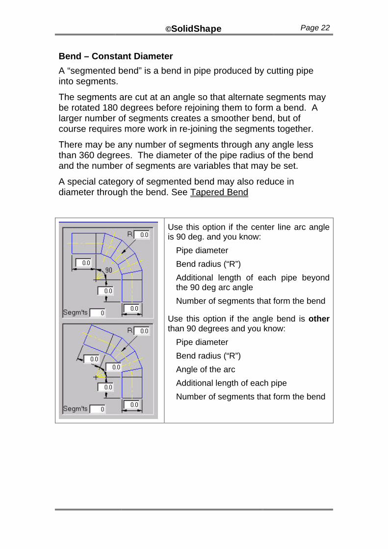
Use this option if the center line arc angle is 90 deg. and you know:
Pipe diameter
Bend radius (“R”)
Additional length of each pipe beyond the 90 deg arc angle
Number of segments that form the bend
Use this option if the angle bend is other than 90 degrees and you know:
Pipe diameter
Bend radius (“R”)
Angle of the arc
Additional length of each pipe
Number of segments that form the bend
©SolidShape Page 23
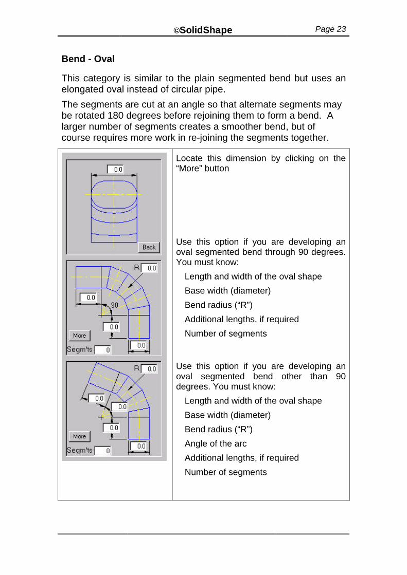
Bend - Oval
This category is similar to the plain segmented bend but uses an elongated oval instead of circular pipe.
The segments are cut at an angle so that alternate segments may be rotated 180 degrees before rejoining them to form a bend. A larger number of segments creates a smoother bend, but of course requires more work in re-joining the segments together.
Locate this dimension by clicking on the “More” button
Use this option if you are developing an oval segmented bend through 90 degrees. You must know:
Length and width of the oval shape
Base width (diameter)
Bend radius (“R”)
Additional lengths, if required
Number of segments
Use this option if you are developing an oval segmented bend other than 90 degrees. You must know:
Length and width of the oval shape
Base width (diameter)
Bend radius (“R”)
Angle of the arc
Additional lengths, if required
Number of segments
©SolidShape Page 24
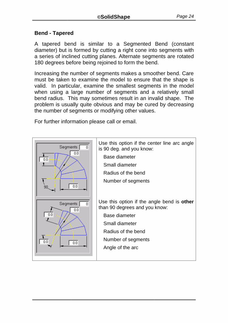
Bend - Tapered
A tapered bend is similar to a Segmented Bend (constant diameter) but is formed by cutting a right cone into segments with a series of inclined cutting planes. Alternate segments are rotated 180 degrees before being rejoined to form the bend.
Increasing the number of segments makes a smoother bend. Care must be taken to examine the model to ensure that the shape is valid. In particular, examine the smallest segments in the model when using a large number of segments and a relatively small bend radius. This may sometimes result in an invalid shape. The problem is usually quite obvious and may be cured by decreasing the number of segments or modifying other values.
For further information please call or email.
Use this option if the center line arc angle is 90 deg. and you know:
Base diameter
Small diameter
Radius of the bend
Number of segments
Use this option if the angle bend is other than 90 degrees and you know:
Base diameter
Small diameter
Radius of the bend
Number of segments
Angle of the arc
©SolidShape Page 25
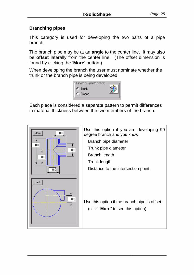
Branching pipes
This category is used for developing the two parts of a pipe branch.
The branch pipe may be at an angle to the center line. It may also be offset laterally from the center line. (The offset dimension is found by clicking the ‘More’ button.)
When developing the branch the user must nominate whether the trunk or the branch pipe is being developed.
Each piece is considered a separate pattern to permit differences in material thickness between the two members of the branch.
Use this option if you are developing 90 degree branch and you know:
Branch pipe diameter
Trunk pipe diameter
Branch length
Trunk length
Distance to the intersection point
Use this option if the branch pipe is offset
(click “More” to see this option)
©SolidShape Page 26
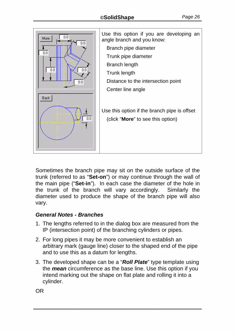
Use this option if you are developing an angle branch and you know:
Branch pipe diameter
Trunk pipe diameter
Branch length
Trunk length
Distance to the intersection point
Center line angle
Use this option if the branch pipe is offset
(click “More” to see this option)
Sometimes the branch pipe may sit on the outside surface of the trunk (referred to as “Set-on”) or may continue through the wall of the main pipe (“Set-in”). In each case the diameter of the hole in the trunk of the branch will vary accordingly. Similarly the diameter used to produce the shape of the branch pipe will also vary.
General Notes - Branches
1. The lengths referred to in the dialog box are measured from the IP (intersection point) of the branching cylinders or pipes.
2. For long pipes it may be more convenient to establish an arbitrary mark (gauge line) closer to the shaped end of the pipe and to use this as a datum for lengths.
3. The developed shape can be a “Roll Plate” type template using the mean circumference as the base line. Use this option if you intend marking out the shape on flat plate and rolling it into a cylinder.
OR
©SolidShape Page 27
4. It can be a “wrap around” type template that uses the outside circumference as the base line for development of the cylinder. Use this if you are using stock pipe sections or are rolling the cylinder prior to cutting the shape.
5. The branch may be of three main types: Set In, Set On or Mean to Mean. The significance of this is discussed below:
Through Pipe B:
As mentioned previously, each pipe in the branch is developed separately to reduce the combination of possible options. The “through” pipe (B) in all cases is treated as the development of a cylinder with a hole penetrating the side wall. It is developed independently of the terminating pipe.
Options are not required for Set In or Set On when developing the through pipe. The following points should be noted, however:
Set In: If the branch is to be of the “set-in” type, the hole size will be the outside diameter of the intersecting pipe.
Set On: If the branch to be of the “set-on” type, the hole size will be the inside diameter of the intersecting pipe.
Mean to mean: If the branch to be of the “mean to mean” type, the selected hole size will be the mean of the intersecting pipe.
©SolidShape Page 28
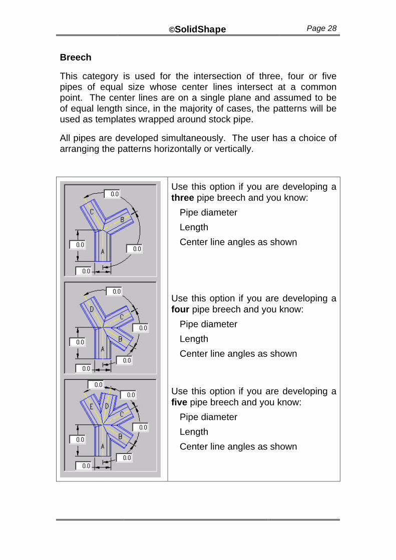
Breech
This category is used for the intersection of three, four or five pipes of equal size whose center lines intersect at a common point. The center lines are on a single plane and assumed to be of equal length since, in the majority of cases, the patterns will be used as templates wrapped around stock pipe.
All pipes are developed simultaneously. The user has a choice of arranging the patterns horizontally or vertically.
Use this option if you are developing a three pipe breech and you know:
Pipe diameter
Length
Center line angles as shown
Use this option if you are developing a four pipe breech and you know:
Pipe diameter
Length
Center line angles as shown
Use this option if you are developing a five pipe breech and you know:
Pipe diameter
Length
Center line angles as shown
©SolidShape Page 29
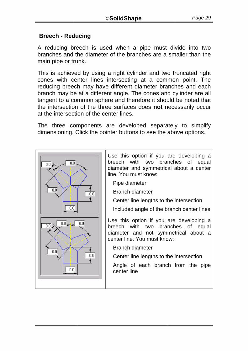
Breech - Reducing
A reducing breech is used when a pipe must divide into two branches and the diameter of the branches are a smaller than the main pipe or trunk.
This is achieved by using a right cylinder and two truncated right cones with center lines intersecting at a common point. The reducing breech may have different diameter branches and each branch may be at a different angle. The cones and cylinder are all tangent to a common sphere and therefore it should be noted that the intersection of the three surfaces does not necessarily occur at the intersection of the center lines.
The three components are developed separately to simplify dimensioning. Click the pointer buttons to see the above options.
Use this option if you are developing a breech with two branches of equal diameter and symmetrical about a center line. You must know:
Pipe diameter
Branch diameter
Center line lengths to the intersection
Included angle of the branch center lines
Use this option if you are developing a breech with two branches of equal diameter and not symmetrical about a center line. You must know:
Branch diameter
Center line lengths to the intersection
Angle of each branch from the pipe center line
©SolidShape Page 30
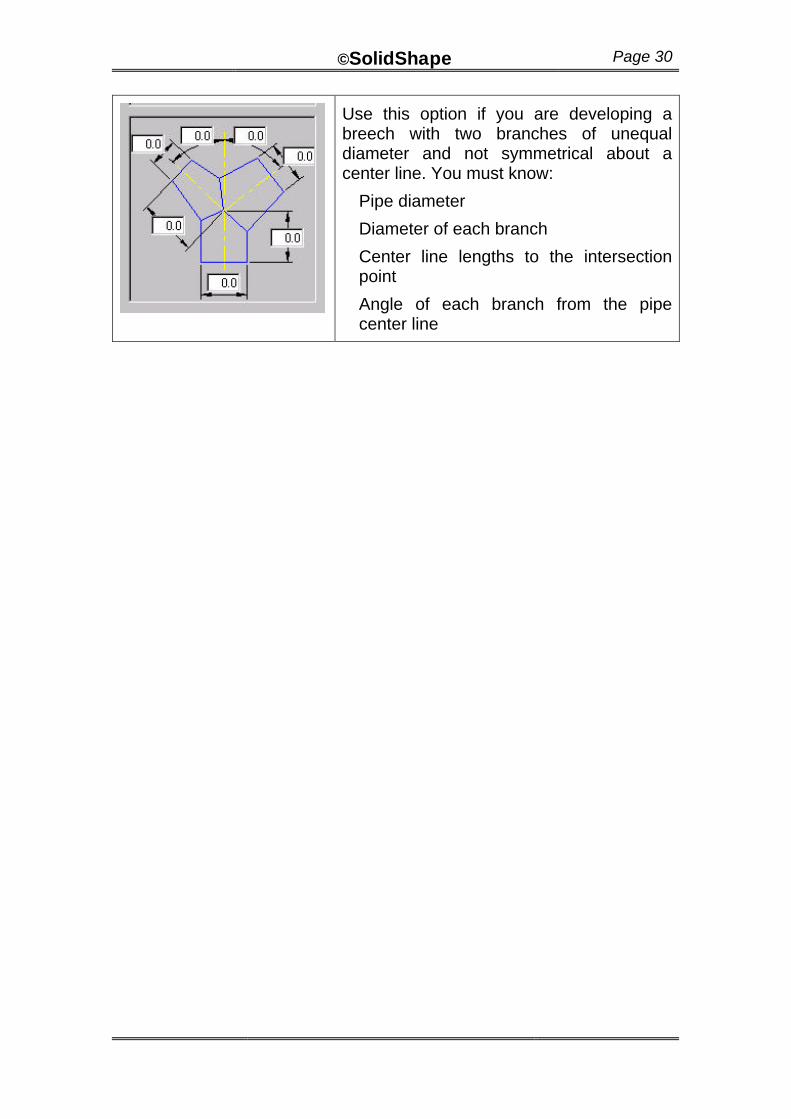
Use this option if you are developing a breech with two branches of unequal diameter and not symmetrical about a center line. You must know:
Pipe diameter
Diameter of each branch
Center line lengths to the intersection point
Angle of each branch from the pipe center line
©SolidShape Page 31
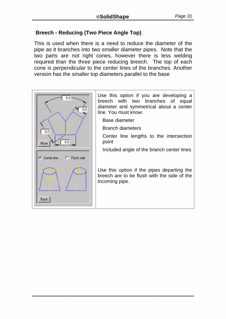
Breech - Reducing (Two Piece Angle Top)
This is used when there is a need to reduce the diameter of the pipe as it branches into two smaller diameter pipes. Note that the two parts are not right cones, however there is less welding required than the three piece reducing breech. The top of each cone is perpendicular to the center lines of the branches. Another version has the smaller top diameters parallel to the base
Use this option if you are developing a breech with two branches of equal diameter and symmetrical about a center line. You must know:
Base diameter
Branch diameters
Center line lengths to the intersection point
Included angle of the branch center lines
Use this option if the pipes departing the breech are to be flush with the side of the incoming pipe.
©SolidShape Page 32
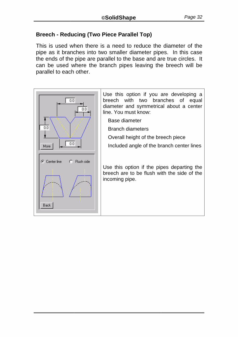
Breech - Reducing (Two Piece Parallel Top)
This is used when there is a need to reduce the diameter of the pipe as it branches into two smaller diameter pipes. In this case the ends of the pipe are parallel to the base and are true circles. It can be used where the branch pipes leaving the breech will be parallel to each other.
Use this option if you are developing a breech with two branches of equal diameter and symmetrical about a center line. You must know:
Base diameter
Branch diameters
Overall height of the breech piece
Included angle of the branch center lines
Use this option if the pipes departing the breech are to be flush with the side of the incoming pipe.
©SolidShape Page 33
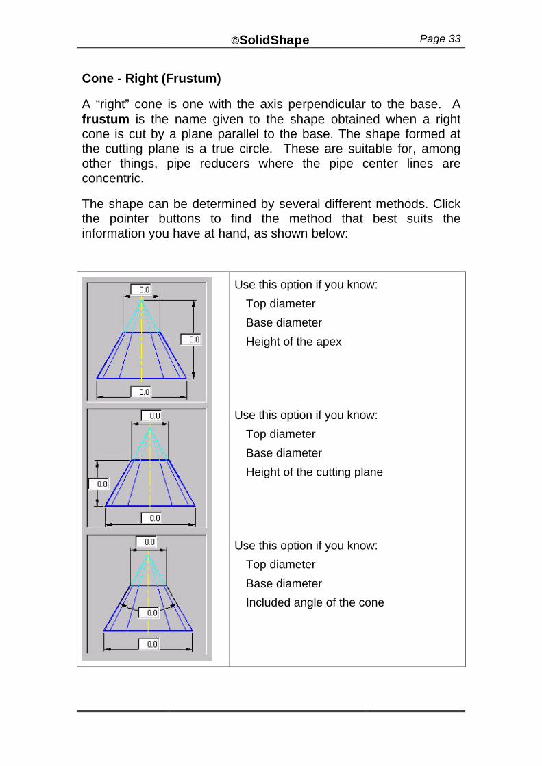
Cone - Right (Frustum)
A “right” cone is one with the axis perpendicular to the base. A frustum is the name given to the shape obtained when a right cone is cut by a plane parallel to the base. The shape formed at the cutting plane is a true circle. These are suitable for, among other things, pipe reducers where the pipe center lines are concentric.
The shape can be determined by several different methods. Click the pointer buttons to find the method that best suits the information you have at hand, as shown below:
Use this option if you know:
Top diameter
Base diameter
Height of the apex
Use this option if you know:
Top diameter
Base diameter
Height of the cutting plane
Use this option if you know:
Top diameter
Base diameter
Included angle of the cone
©SolidShape Page 34
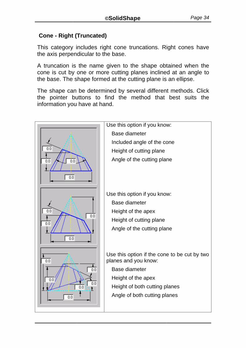
Cone - Right (Truncated)
This category includes right cone truncations. Right cones have the axis perpendicular to the base.
A truncation is the name given to the shape obtained when the cone is cut by one or more cutting planes inclined at an angle to the base. The shape formed at the cutting plane is an ellipse.
The shape can be determined by several different methods. Click the pointer buttons to find the method that best suits the information you have at hand.
Use this option if you know:
Base diameter
Included angle of the cone
Height of cutting plane
Angle of the cutting plane
Use this option if you know:
Base diameter
Height of the apex
Height of cutting plane
Angle of the cutting plane
Use this option if the cone to be cut by two planes and you know:
Base diameter
Height of the apex
Height of both cutting planes
Angle of both cutting planes
©SolidShape Page 35
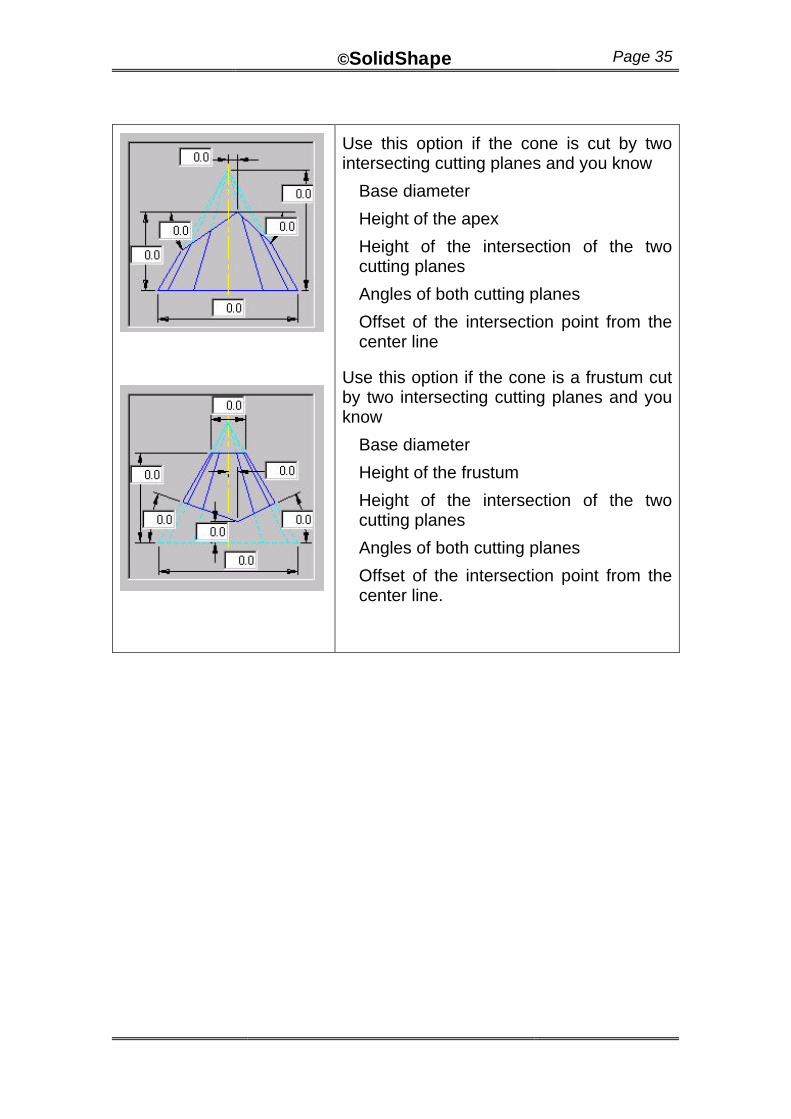
Use this option if the cone is cut by two intersecting cutting planes and you know
Base diameter
Height of the apex
Height of the intersection of the two cutting planes
Angles of both cutting planes
Offset of the intersection point from the center line
Use this option if the cone is a frustum cut by two intersecting cutting planes and you know
Base diameter
Height of the frustum
Height of the intersection of the two cutting planes
Angles of both cutting planes
Offset of the intersection point from the center line.
©SolidShape Page 36
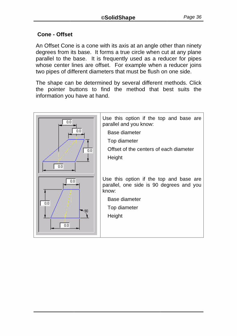
Cone - Offset
An Offset Cone is a cone with its axis at an angle other than ninety degrees from its base. It forms a true circle when cut at any plane parallel to the base. It is frequently used as a reducer for pipes whose center lines are offset. For example when a reducer joins two pipes of different diameters that must be flush on one side.
The shape can be determined by several different methods. Click the pointer buttons to find the method that best suits the information you have at hand.
Use this option if the top and base are parallel and you know:
Base diameter
Top diameter
Offset of the centers of each diameter
Height
Use this option if the top and base are parallel, one side is 90 degrees and you know:
Base diameter
Top diameter
Height

©SolidShape Page 37
Cyclone (Cylinder)
This category is a special case of the branch development where the branch pipe enters the cylinder at a tangent to the side of the cylinder. It may be used for the inlet to a tank or vessel.
Use this when the pipe is horizontal. You must know:
Base diameter of the large cylinder
Diameter of the smaller pipe
Height of the large cylinder
Height of the pipe center line
Length of the pipe measured from the intersection point.
©SolidShape Page 38
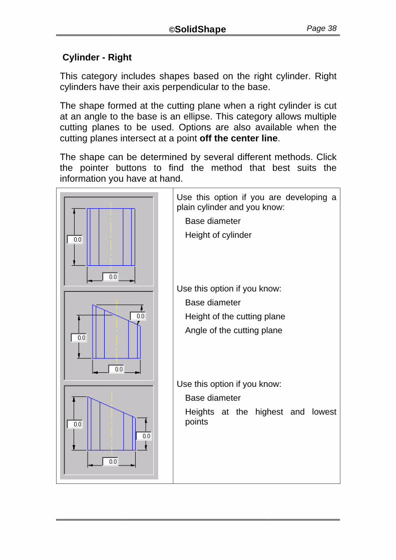
Cylinder - Right
This category includes shapes based on the right cylinder. Right cylinders have their axis perpendicular to the base.
The shape formed at the cutting plane when a right cylinder is cut at an angle to the base is an ellipse. This category allows multiple cutting planes to be used. Options are also available when the cutting planes intersect at a point off the center line.
The shape can be determined by several different methods. Click the pointer buttons to find the method that best suits the information you have at hand.
Use this option if you are developing a plain cylinder and you know:
Base diameter
Height of cylinder
Use this option if you know:
Base diameter
Height of the cutting plane
Angle of the cutting plane
Use this option if you know:
Base diameter
Heights at the highest and lowest points

©SolidShape Page 39
Use this option if the cylinder is cut by two planes which intersect on the center line and you know:
Height of the intersection point
Angles of the two cutting planes
Use this option if the cylinder is cut by two planes which do not intersect and you know:
Height of both cutting planes
Angles of the two cutting planes
Rotation of the cutting planes (Note: the planes may be both inclined and rotated relative to each other. A rotation of zero produces a shape similar to that shown.)
Use this option if the cylinder is cut by two planes which do NOT necessarily intersect on the center line and you know:
Base diameter
Height of the intersection point
Angles of the two cutting planes
Offset of the intersection point from the center line
©SolidShape Page 40
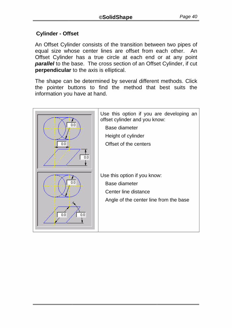
Cylinder - Offset
An Offset Cylinder consists of the transition between two pipes of equal size whose center lines are offset from each other. An Offset Cylinder has a true circle at each end or at any point parallel to the base. The cross section of an Offset Cylinder, if cut perpendicular to the axis is elliptical.
The shape can be determined by several different methods. Click the pointer buttons to find the method that best suits the information you have at hand.
Use this option if you are developing an offset cylinder and you know:
Base diameter
Height of cylinder
Offset of the centers
Use this option if you know:
Base diameter
Center line distance
Angle of the center line from the base
©SolidShape Page 41
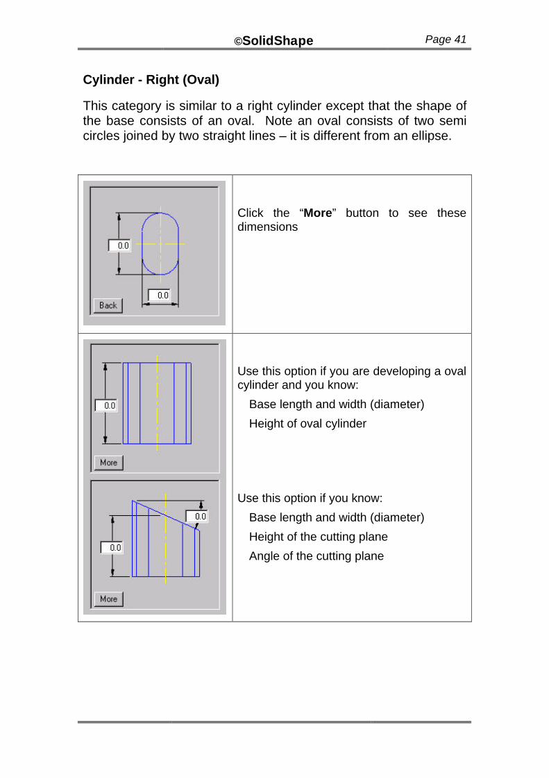
Cylinder - Right (Oval)
This category is similar to a right cylinder except that the shape of the base consists of an oval. Note an oval consists of two semi circles joined by two straight lines – it is different from an ellipse.
Click the “More” button to see these dimensions
Use this option if you are developing a oval cylinder and you know:
Base length and width (diameter)
Height of oval cylinder
Use this option if you know:
Base length and width (diameter)
Height of the cutting plane
Angle of the cutting plane
©SolidShape Page 42
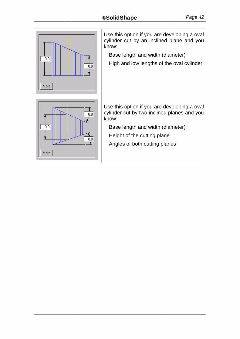
Use this option if you are developing a oval cylinder cut by an inclined plane and you know:
Base length and width (diameter)
High and low lengths of the oval cylinder
Use this option if you are developing a oval cylinder cut by two inclined planes and you know:
Base length and width (diameter)
Height of the cutting plane
Angles of both cutting planes
©SolidShape Page 43
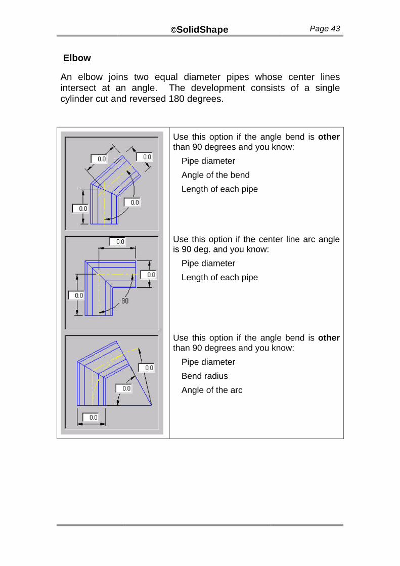
Elbow
An elbow joins two equal diameter pipes whose center lines intersect at an angle. The development consists of a single cylinder cut and reversed 180 degrees.
Use this option if the angle bend is other than 90 degrees and you know:
Pipe diameter
Angle of the bend
Length of each pipe
Use this option if the center line arc angle is 90 deg. and you know:
Pipe diameter
Length of each pipe
Use this option if the angle bend is other than 90 degrees and you know:
Pipe diameter
Bend radius
Angle of the arc
©SolidShape Page 44
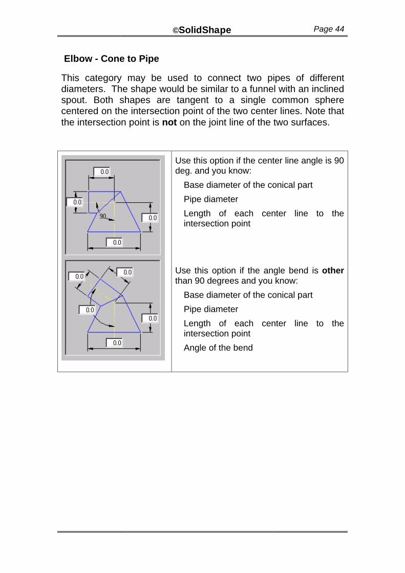
Elbow - Cone to Pipe
This category may be used to connect two pipes of different diameters. The shape would be similar to a funnel with an inclined spout. Both shapes are tangent to a single common sphere centered on the intersection point of the two center lines. Note that the intersection point is not on the joint line of the two surfaces.
Use this option if the center line angle is 90 deg. and you know:
Base diameter of the conical part
Pipe diameter
Length of each center line to the intersection point
Use this option if the angle bend is other than 90 degrees and you know:
Base diameter of the conical part
Pipe diameter
Length of each center line to the intersection point
Angle of the bend
©SolidShape Page 45
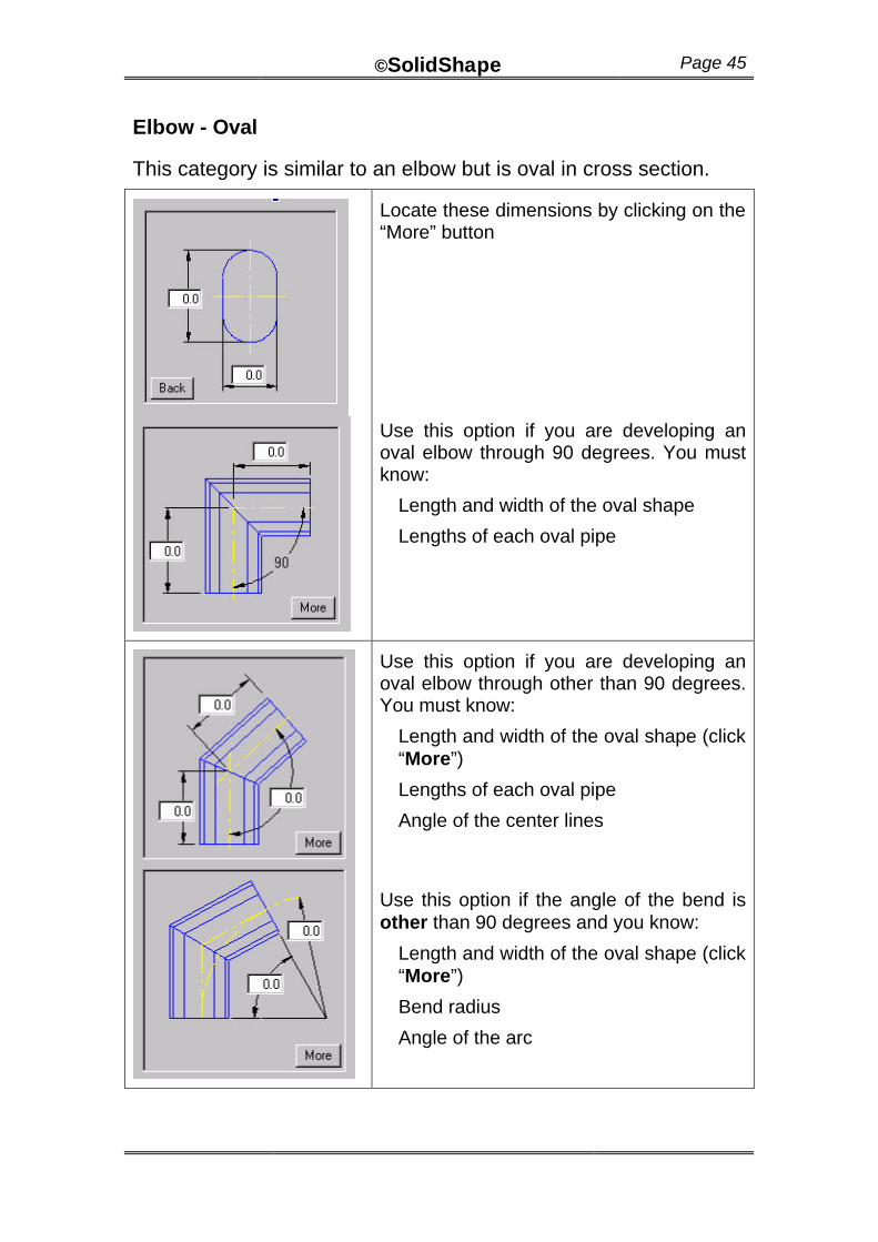
Elbow - Oval
This category is similar to an elbow but is oval in cross section.
Locate these dimensions by clicking on the “More” button
Use this option if you are developing an oval elbow through 90 degrees. You must know:
Length and width of the oval shape
Lengths of each oval pipe
Use this option if you are developing an oval elbow through other than 90 degrees. You must know:
Length and width of the oval shape (click “More”)
Lengths of each oval pipe
Angle of the center lines
Use this option if the angle of the bend is other than 90 degrees and you know:
Length and width of the oval shape (click “More”)
Bend radius
Angle of the arc
©SolidShape Page 46
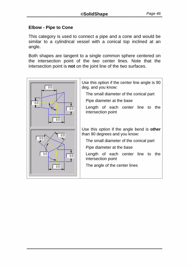
Elbow - Pipe to Cone
This category is used to connect a pipe and a cone and would be similar to a cylindrical vessel with a conical top inclined at an angle.
Both shapes are tangent to a single common sphere centered on the intersection point of the two center lines. Note that the intersection point is not on the joint line of the two surfaces.
Use this option if the center line angle is 90 deg. and you know:
The small diameter of the conical part
Pipe diameter at the base
Length of each center line to the intersection point
Use this option if the angle bend is other than 90 degrees and you know:
The small diameter of the conical part
Pipe diameter at the base
Length of each center line to the intersection point
The angle of the center lines
©SolidShape Page 47
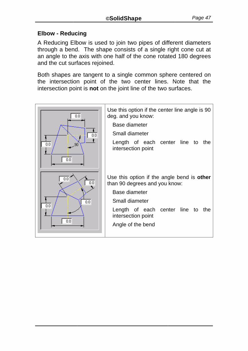
Elbow - Reducing
A Reducing Elbow is used to join two pipes of different diameters through a bend. The shape consists of a single right cone cut at an angle to the axis with one half of the cone rotated 180 degrees and the cut surfaces rejoined.
Both shapes are tangent to a single common sphere centered on the intersection point of the two center lines. Note that the intersection point is not on the joint line of the two surfaces.
Use this option if the center line angle is 90 deg. and you know:
Base diameter
Small diameter
Length of each center line to the intersection point
Use this option if the angle bend is other than 90 degrees and you know:
Base diameter
Small diameter
Length of each center line to the intersection point
Angle of the bend
©SolidShape Page 48
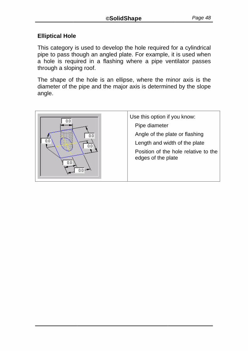
Elliptical Hole
This category is used to develop the hole required for a cylindrical pipe to pass though an angled plate. For example, it is used when a hole is required in a flashing where a pipe ventilator passes through a sloping roof.
The shape of the hole is an ellipse, where the minor axis is the diameter of the pipe and the major axis is determined by the slope angle.
Use this option if you know:
Pipe diameter
Angle of the plate or flashing
Length and width of the plate
Position of the hole relative to the edges of the plate
©SolidShape Page 49
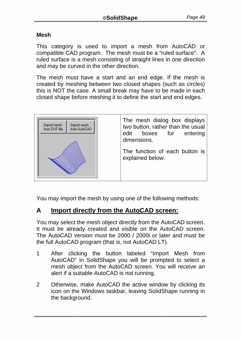
Mesh
This category is used to import a mesh from AutoCAD or compatible CAD program. The mesh must be a “ruled surface”. A ruled surface is a mesh consisting of straight lines in one direction and may be curved in the other direction.
The mesh must have a start and an end edge. If the mesh is created by meshing between two closed shapes (such as circles) this is NOT the case. A small break may have to be made in each closed shape before meshing it to define the start and end edges.
The mesh dialog box displays two button, rather than the usual edit boxes for entering dimensions.
The function of each button is explained below.
You may import the mesh by using one of the following methods:
A Import directly from the AutoCAD screen:
You may select the mesh object directly from the AutoCAD screen. It must be already created and visible on the AutoCAD screen. The AutoCAD version must be 2000 / 2000i or later and must be the full AutoCAD program (that is, not AutoCAD LT).
1 After clicking the button labeled “Import Mesh from AutoCAD” in SolidShape you will be prompted to select a mesh object from the AutoCAD screen. You will receive an alert if a suitable AutoCAD is not running.
2 Otherwise, make AutoCAD the active window by clicking its icon on the Windows taskbar, leaving SolidShape running in the background.
©SolidShape Page 50
3 The AutoCAD command line will now be prompting you to select a mesh. Select it by clicking on one of the mesh lines with the left mouse button.
4 Next, click the SolidShape icon on the taskbar and the mesh will be imported into the SolidShape session. It may not be visible until you select a view and ‘zoom extents’.
B Import the mesh from an existing DXF file.
Use this method if you don’t have an AutoCAD version as described above. The mesh may be created in any CAD program with this capability and saved or exported as a DXF file.
1 Click the “Import Mesh from DXF file” button and select a DXF file.
2 The import program will scan through the DXF and find the first suitable mesh, ignoring all other entities and additional mesh objects.
3 Select a view and zoom extents to see the mesh.
4 The most reliable results will therefore be achieved by selecting a single mesh object for DXF translation in the CAD program used to create it. In AutoCAD this means using the ‘Entities’ or objects option of the DXFOut command.
(A sample of the DXF specification can be made available by contacting the supplier of this software.)
©SolidShape Page 51
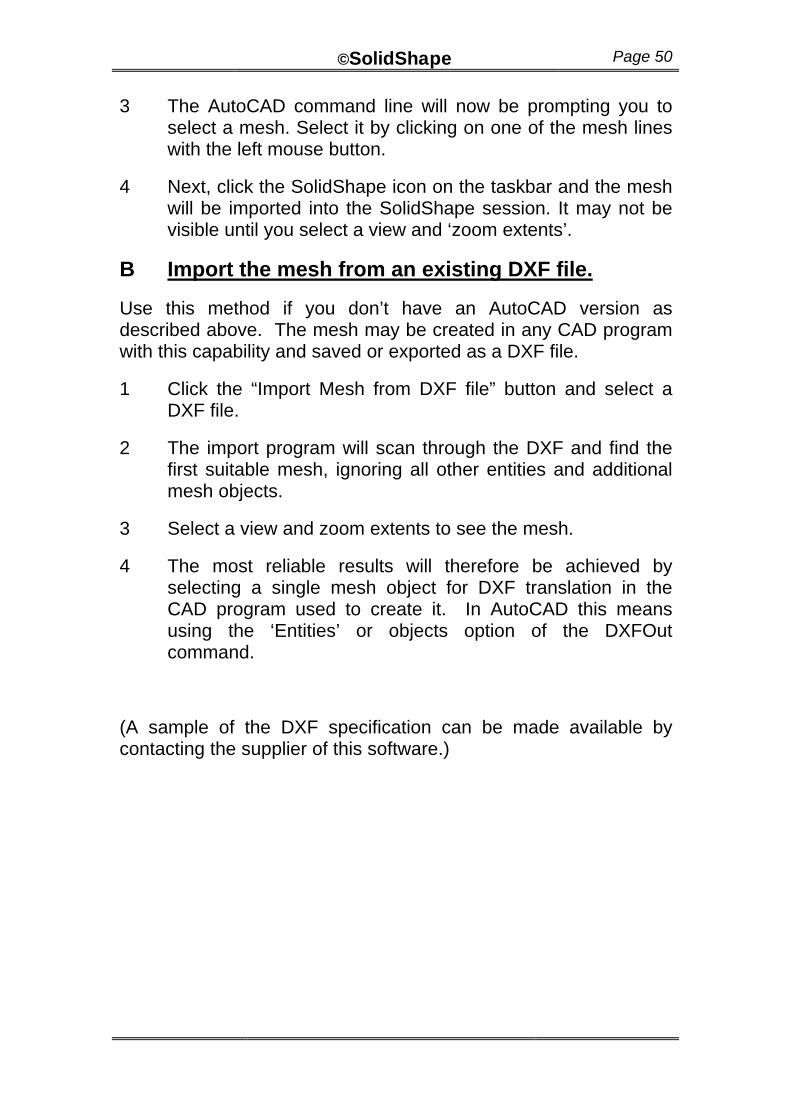
Oval to Oval
This category is the transition between two oval shapes of different dimensions. An oval is different than an ellipse. It can be considered as a cylinder cut in half and rejoined with flat sides.
Use this option if you are developing an oval cylinder which are concentric and parallel. You must know:
Base length
Base width (diameter)
Top length
Top width (diameter)
Height (click the “More” button to see the height parameter)
©SolidShape Page 52
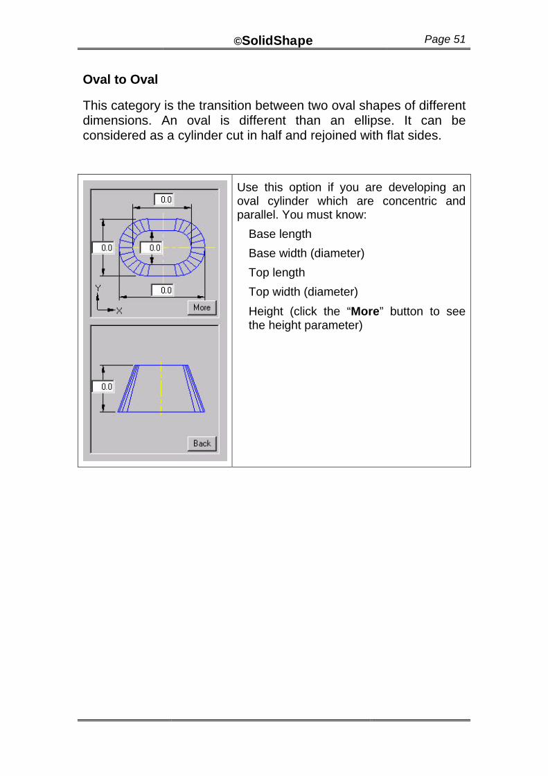
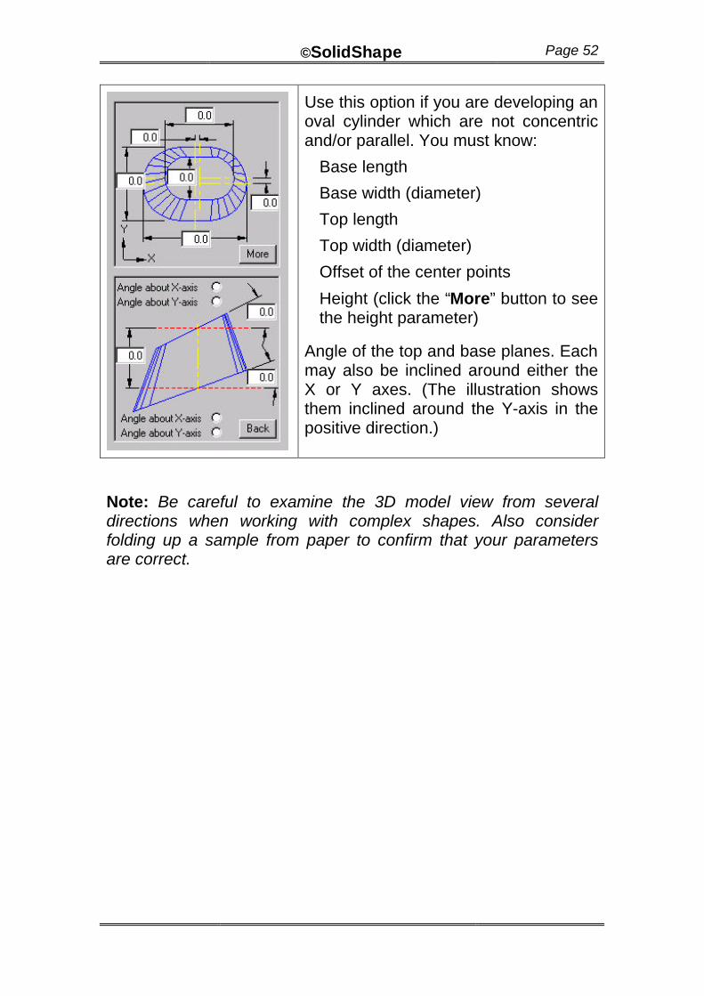
Use this option if you are developing an oval cylinder which are not concentric and/or parallel. You must know:
Base length
Base width (diameter)
Top length
Top width (diameter)
Offset of the center points
Height (click the “More” button to see the height parameter)
Angle of the top and base planes. Each may also be inclined around either the X or Y axes. (The illustration shows them inclined around the Y-axis in the positive direction.)
Note: Be careful to examine the 3D model view from several directions when working with complex shapes. Also consider folding up a sample from paper to confirm that your parameters are correct.
©SolidShape Page 53
Pipe to Cone
This category is used for a branch between a pipe and a right cone. There are three basic types are with the horizontal pipe, the vertical pipe, and the pipe at any angle (other than the above).
When developing the branch the user must nominate whether the cone or the branch pipe is being developed. Each piece is considered a separate pattern. This is because there may be differences in material thickness between the two parts.
Sometimes the branch pipe may sit on the outside surface of the cone (that is, “set-on” or butt welded joint). Alternatively, it may continue through the wall of the cone. In each case the diameter of the hole in the cone will vary according to whether the cone or pipe is being developed.
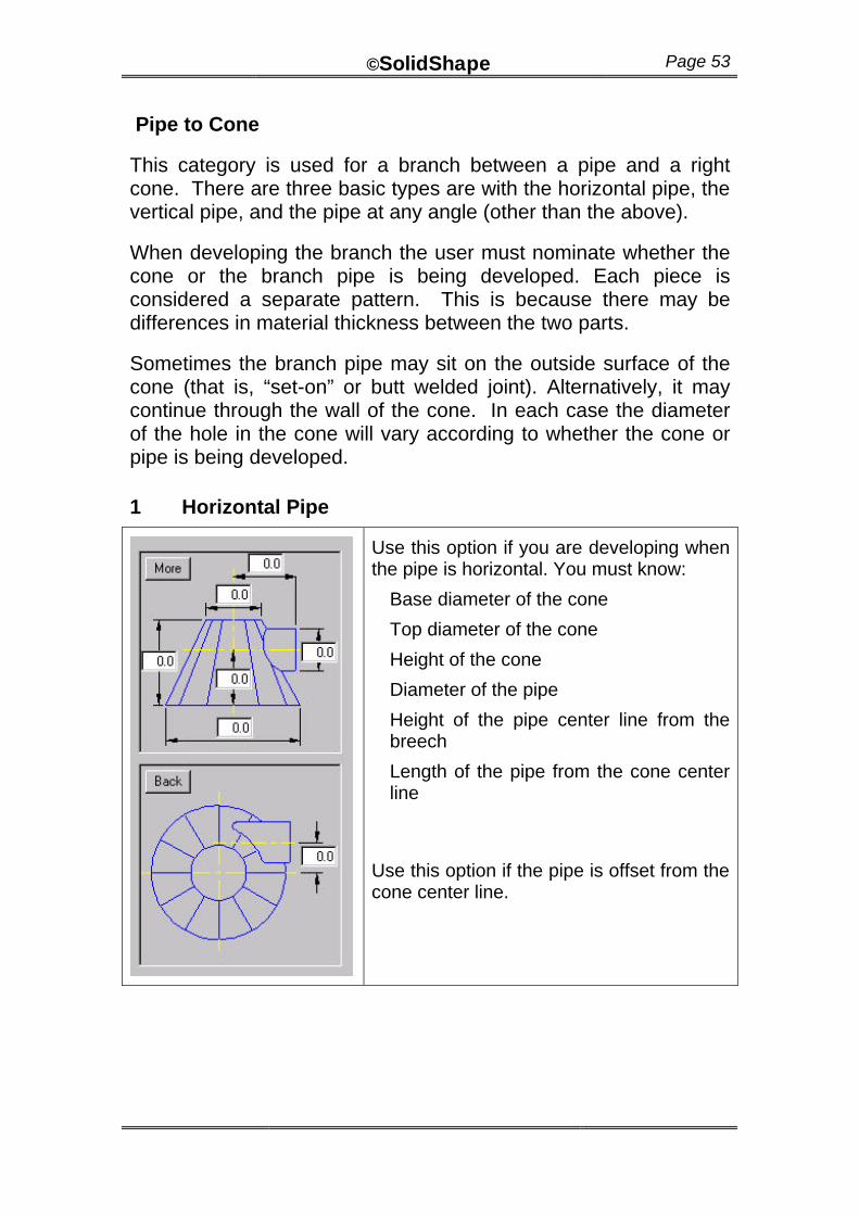
1 Horizontal Pipe
Use this option if you are developing when the pipe is horizontal. You must know:
Base diameter of the cone
Top diameter of the cone
Height of the cone
Diameter of the pipe
Height of the pipe center line from the breech
Length of the pipe from the cone center line
Use this option if the pipe is offset from the cone center line.
©SolidShape Page 54
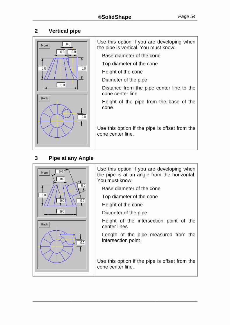
2 Vertical pipe
Use this option if you are developing when the pipe is vertical. You must know:
Base diameter of the cone
Top diameter of the cone
Height of the cone
Diameter of the pipe
Distance from the pipe center line to the cone center line
Height of the pipe from the base of the cone
Use this option if the pipe is offset from the cone center line.
3 Pipe at any Angle
Use this option if you are developing when the pipe is at an angle from the horizontal. You must know:
Base diameter of the cone
Top diameter of the cone
Height of the cone
Diameter of the pipe
Height of the intersection point of the center lines
Length of the pipe measured from the intersection point
Use this option if the pipe is offset from the cone center line.
©SolidShape Page 55
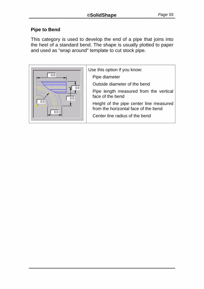
Pipe to Bend
This category is used to develop the end of a pipe that joins into the heel of a standard bend. The shape is usually plotted to paper and used as “wrap around” template to cut stock pipe.
Use this option if you know:
Pipe diameter
Outside diameter of the bend
Pipe length measured from the vertical face of the bend
Height of the pipe center line measured from the horizontal face of the bend
Center line radius of the bend
©SolidShape Page 56
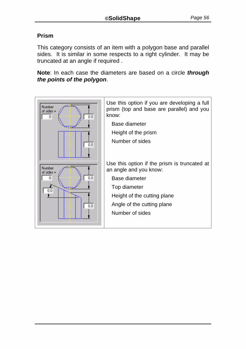
Prism
This category consists of an item with a polygon base and parallel sides. It is similar in some respects to a right cylinder. It may be truncated at an angle if required .
Note: In each case the diameters are based on a circle through the points of the polygon.
Use this option if you are developing a full prism (top and base are parallel) and you know:
Base diameter
Height of the prism
Number of sides
Use this option if the prism is truncated at an angle and you know:
Base diameter
Top diameter
Height of the cutting plane
Angle of the cutting plane
Number of sides
©SolidShape Page 57
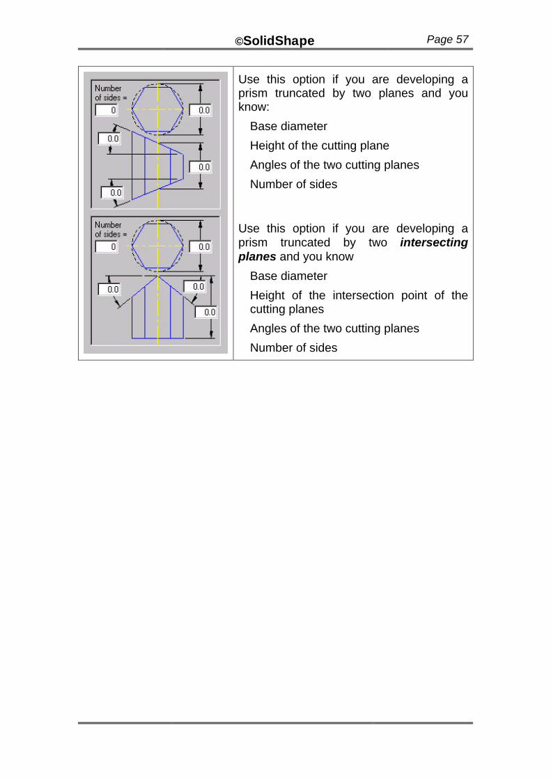
Use this option if you are developing a prism truncated by two planes and you know:
Base diameter
Height of the cutting plane
Angles of the two cutting planes
Number of sides
Use this option if you are developing a prism truncated by two intersecting planes and you know
Base diameter
Height of the intersection point of the cutting planes
Angles of the two cutting planes
Number of sides
©SolidShape Page 58
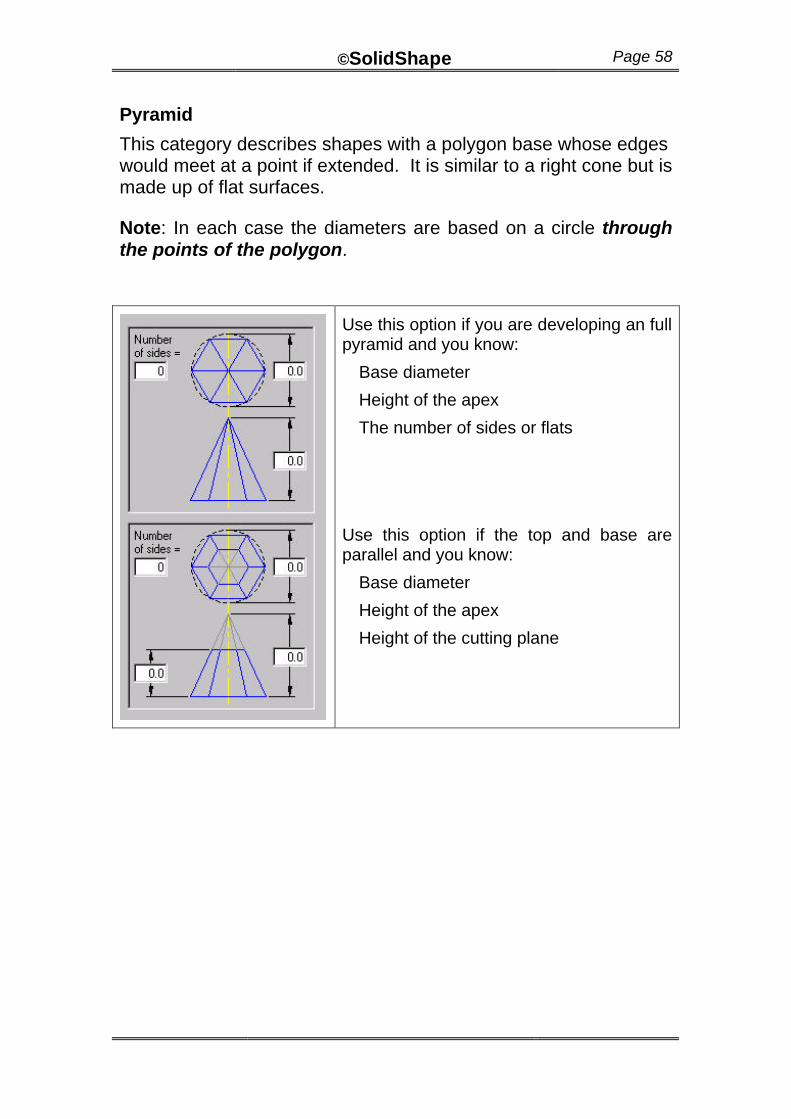
Pyramid
This category describes shapes with a polygon base whose edges would meet at a point if extended. It is similar to a right cone but is made up of flat surfaces.
Note: In each case the diameters are based on a circle through the points of the polygon.
Use this option if you are developing an full pyramid and you know:
Base diameter
Height of the apex
The number of sides or flats
Use this option if the top and base are parallel and you know:
Base diameter
Height of the apex
Height of the cutting plane
©SolidShape Page 59
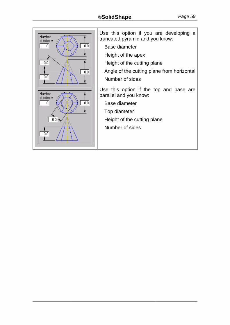
Use this option if you are developing a truncated pyramid and you know:
Base diameter
Height of the apex
Height of the cutting plane
Angle of the cutting plane from horizontal
Number of sides
Use this option if the top and base are parallel and you know:
Base diameter
Top diameter
Height of the cutting plane
Number of sides
©SolidShape Page 60
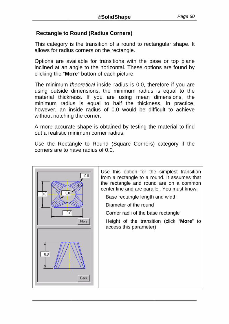
Rectangle to Round (Radius Corners)
This category is the transition of a round to rectangular shape. It allows for radius corners on the rectangle.
Options are available for transitions with the base or top plane inclined at an angle to the horizontal. These options are found by clicking the “More” button of each picture.
The minimum theoretical inside radius is 0.0, therefore if you are using outside dimensions, the minimum radius is equal to the material thickness. If you are using mean dimensions, the minimum radius is equal to half the thickness. In practice, however, an inside radius of 0.0 would be difficult to achieve without notching the corner.
A more accurate shape is obtained by testing the material to find out a realistic minimum corner radius.
Use the Rectangle to Round (Square Corners) category if the corners are to have radius of 0.0.
Use this option for the simplest transition from a rectangle to a round. It assumes that the rectangle and round are on a common center line and are parallel. You must know:
Base rectangle length and width
Diameter of the round
Corner radii of the base rectangle
Height of the transition (click “More” to access this parameter)
©SolidShape Page 61
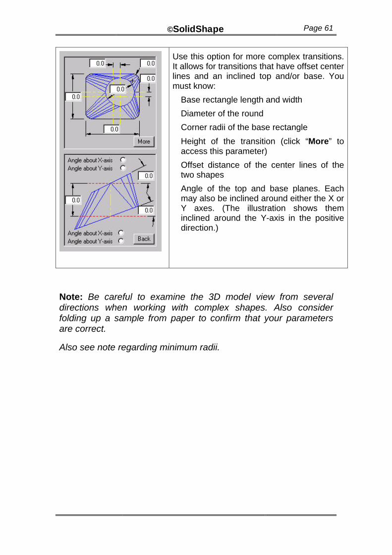
Use this option for more complex transitions. It allows for transitions that have offset center lines and an inclined top and/or base. You must know:
Base rectangle length and width
Diameter of the round
Corner radii of the base rectangle
Height of the transition (click “More” to access this parameter)
Offset distance of the center lines of the two shapes
Angle of the top and base planes. Each may also be inclined around either the X or Y axes. (The illustration shows them inclined around the Y-axis in the positive direction.)
Note: Be careful to examine the 3D model view from several directions when working with complex shapes. Also consider folding up a sample from paper to confirm that your parameters are correct.
Also see note regarding minimum radii.
©SolidShape Page 62
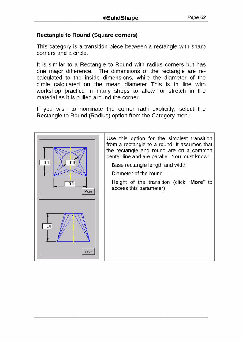
Rectangle to Round (Square corners)
This category is a transition piece between a rectangle with sharp corners and a circle.
It is similar to a Rectangle to Round with radius corners but has one major difference. The dimensions of the rectangle are re-calculated to the inside dimensions, while the diameter of the circle calculated on the mean diameter This is in line with workshop practice in many shops to allow for stretch in the material as it is pulled around the corner.
If you wish to nominate the corner radii explicitly, select the Rectangle to Round (Radius) option from the Category menu.
Use this option for the simplest transition from a rectangle to a round. It assumes that the rectangle and round are on a common center line and are parallel. You must know:
Base rectangle length and width
Diameter of the round
Height of the transition (click “More” to access this parameter)
©SolidShape Page 63
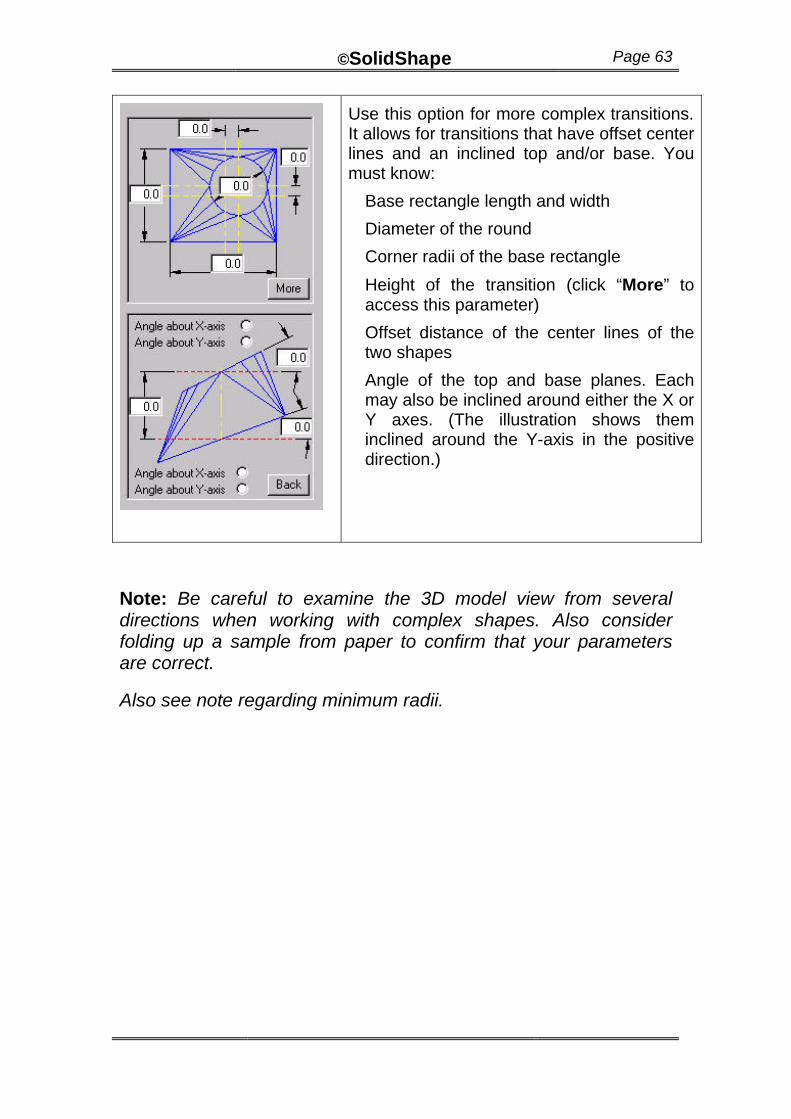
Use this option for more complex transitions. It allows for transitions that have offset center lines and an inclined top and/or base. You must know:
Base rectangle length and width
Diameter of the round
Corner radii of the base rectangle
Height of the transition (click “More” to access this parameter)
Offset distance of the center lines of the two shapes
Angle of the top and base planes. Each may also be inclined around either the X or Y axes. (The illustration shows them inclined around the Y-axis in the positive direction.)
Note: Be careful to examine the 3D model view from several directions when working with complex shapes. Also consider folding up a sample from paper to confirm that your parameters are correct.
Also see note regarding minimum radii.
©SolidShape Page 64
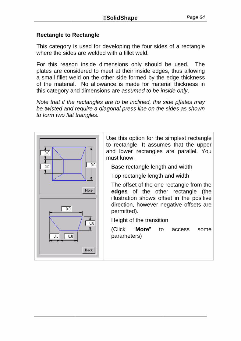
Rectangle to Rectangle
This category is used for developing the four sides of a rectangle where the sides are welded with a fillet weld.
For this reason inside dimensions only should be used. The plates are considered to meet at their inside edges, thus allowing a small fillet weld on the other side formed by the edge thickness of the material. No allowance is made for material thickness in this category and dimensions are assumed to be inside only.
Note that if the rectangles are to be inclined, the side p[lates may be twisted and require a diagonal press line on the sides as shown to form two flat triangles.
Use this option for the simplest rectangle to rectangle. It assumes that the upper and lower rectangles are parallel. You must know:
Base rectangle length and width
Top rectangle length and width
The offset of the one rectangle from the edges of the other rectangle (the illustration shows offset in the positive direction, however negative offsets are permitted).
Height of the transition
(Click “More” to access some parameters)
©SolidShape Page 65
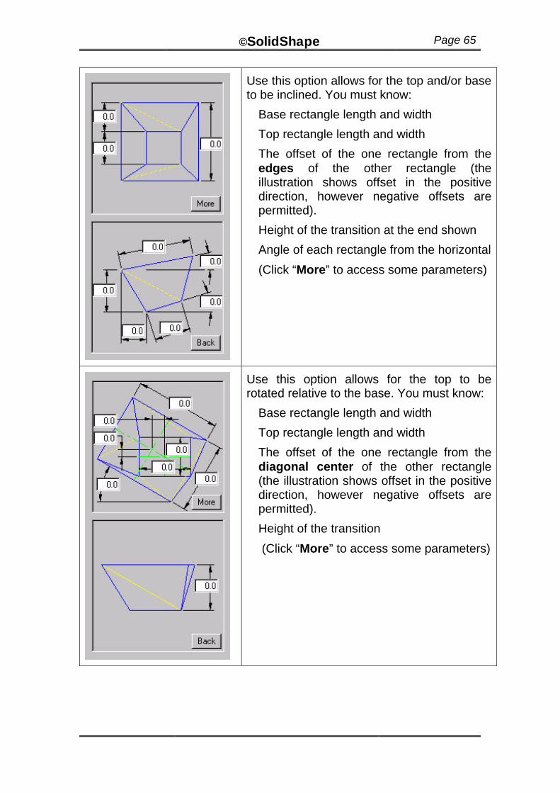
Use this option allows for the top and/or base to be inclined. You must know:
Base rectangle length and width
Top rectangle length and width
The offset of the one rectangle from the edges of the other rectangle (the illustration shows offset in the positive direction, however negative offsets are permitted).
Height of the transition at the end shown
Angle of each rectangle from the horizontal
(Click “More” to access some parameters)
Use this option allows for the top to be rotated relative to the base. You must know:
Base rectangle length and width
Top rectangle length and width
The offset of the one rectangle from the diagonal center of the other rectangle (the illustration shows offset in the positive direction, however negative offsets are permitted).
Height of the transition
(Click “More” to access some parameters)
©SolidShape Page 66
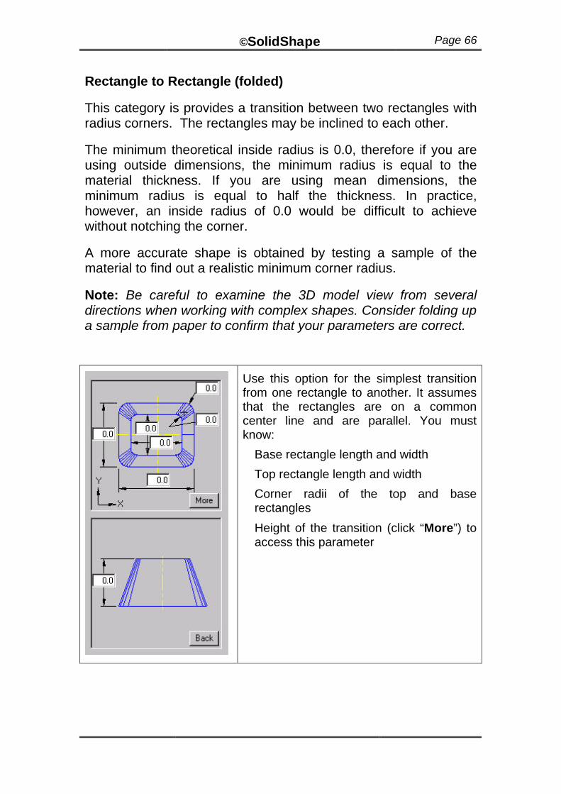
Rectangle to Rectangle (folded)
This category is provides a transition between two rectangles with radius corners. The rectangles may be inclined to each other.
The minimum theoretical inside radius is 0.0, therefore if you are using outside dimensions, the minimum radius is equal to the material thickness. If you are using mean dimensions, the minimum radius is equal to half the thickness. In practice, however, an inside radius of 0.0 would be difficult to achieve without notching the corner.
A more accurate shape is obtained by testing a sample of the material to find out a realistic minimum corner radius.
Note: Be careful to examine the 3D model view from several directions when working with complex shapes. Consider folding up a sample from paper to confirm that your parameters are correct.
Use this option for the simplest transition from one rectangle to another. It assumes that the rectangles are on a common center line and are parallel. You must know:
Base rectangle length and width
Top rectangle length and width
Corner radii of the top and base rectangles
Height of the transition (click “More”) to access this parameter
©SolidShape Page 67
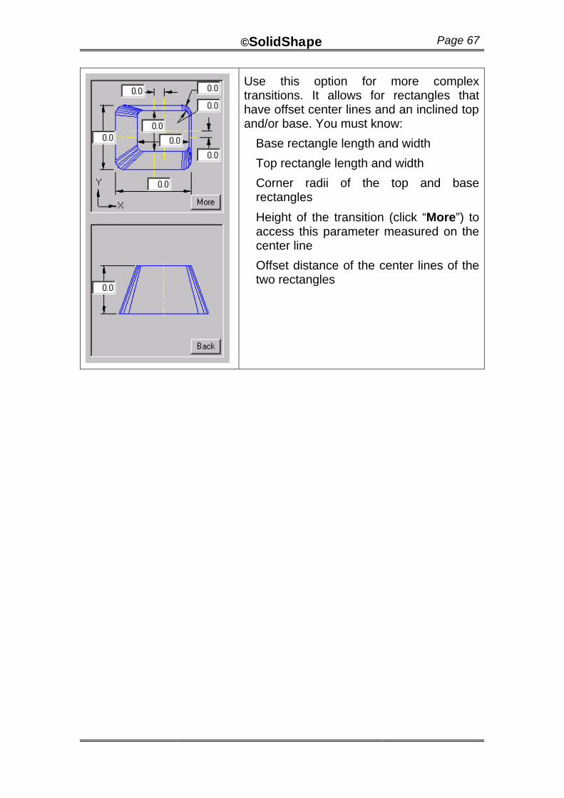
Use this option for more complex transitions. It allows for rectangles that have offset center lines and an inclined top and/or base. You must know:
Base rectangle length and width
Top rectangle length and width
Corner radii of the top and base rectangles
Height of the transition (click “More”) to access this parameter measured on the center line
Offset distance of the center lines of the two rectangles
©SolidShape Page 68
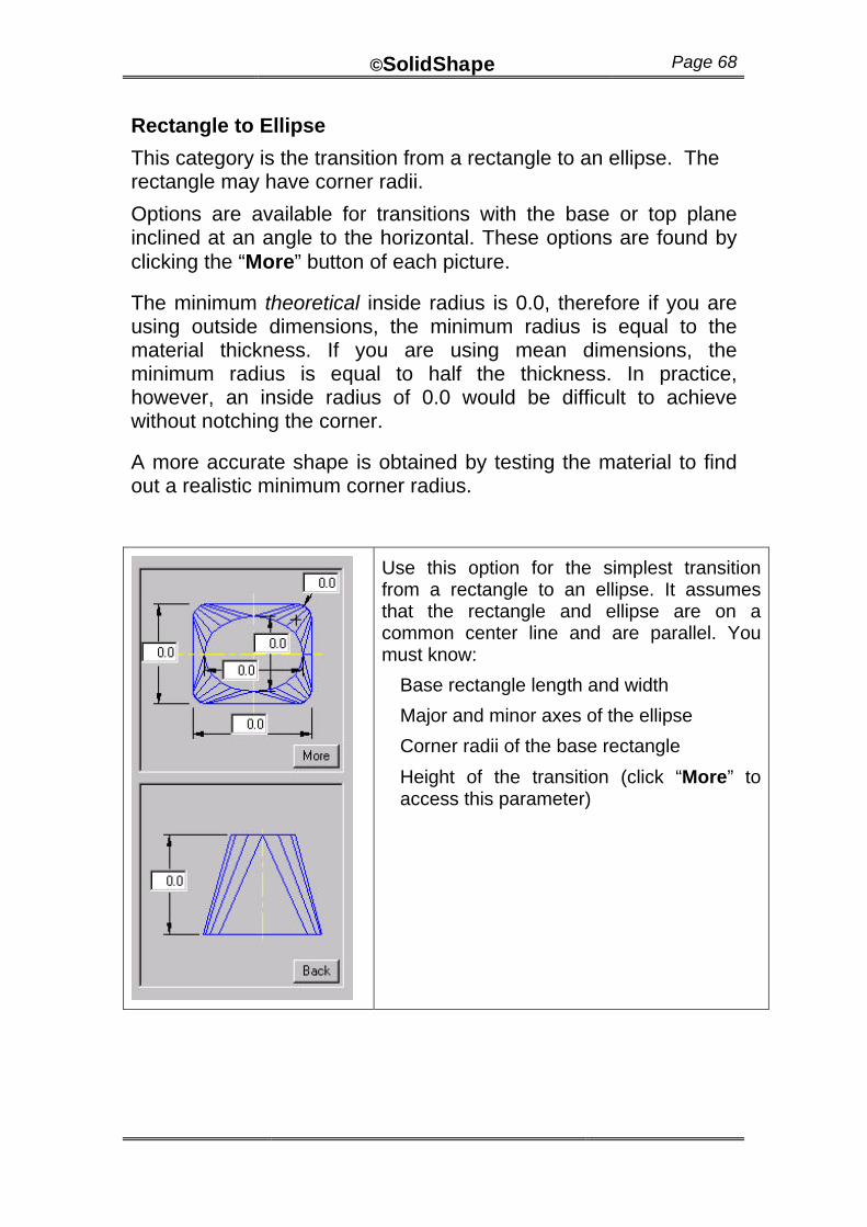
Rectangle to Ellipse
This category is the transition from a rectangle to an ellipse. The rectangle may have corner radii.
Options are available for transitions with the base or top plane inclined at an angle to the horizontal. These options are found by clicking the “More” button of each picture.
The minimum theoretical inside radius is 0.0, therefore if you are using outside dimensions, the minimum radius is equal to the material thickness. If you are using mean dimensions, the minimum radius is equal to half the thickness. In practice, however, an inside radius of 0.0 would be difficult to achieve without notching the corner.
A more accurate shape is obtained by testing the material to find out a realistic minimum corner radius.
Use this option for the simplest transition from a rectangle to an ellipse. It assumes that the rectangle and ellipse are on a common center line and are parallel. You must know:
Base rectangle length and width
Major and minor axes of the ellipse
Corner radii of the base rectangle
Height of the transition (click “More” to access this parameter)
©SolidShape Page 69
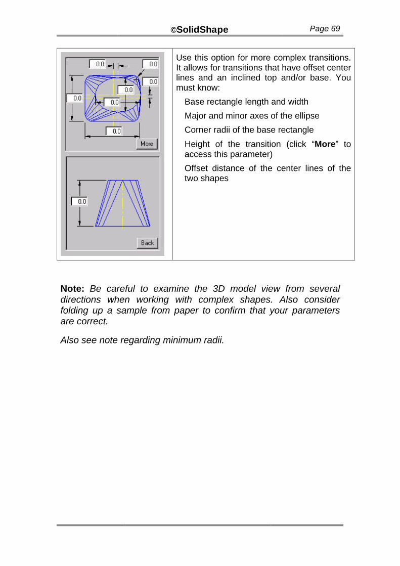
Use this option for more complex transitions. It allows for transitions that have offset center lines and an inclined top and/or base. You must know:
Base rectangle length and width
Major and minor axes of the ellipse
Corner radii of the base rectangle
Height of the transition (click “More” to access this parameter)
Offset distance of the center lines of the two shapes
Note: Be careful to examine the 3D model view from several directions when working with complex shapes. Also consider folding up a sample from paper to confirm that your parameters are correct.
Also see note regarding minimum radii.

©SolidShape Page 70
Round to Round
This category is a transition piece between two circles. Although some shapes may look like a truncated right cone, this shape provides a true circle at each end of the transition (while a truncated cone is elliptical).
Use this option for the simplest transition from a round to a round. It assumes that the both circles are on a common center line. You must know:
Base diameter
Top diameter
Height at the center line
Angle of the top circular face
Use this option when the top round is inclined and offset. You must know:
Base diameter
Top diameter
Height at the center line
Angle of the top circular face
Offset of the top center
Use this option when the top round is at 90 degrees to the base and offset from the center line. You must know:
Base diameter
Top diameter
Height at the center line
Offset of the top face from the center line of the base
Options are available for transitions with the base or top plane inclined at an angle to the horizontal and for the circles to be offset from each other.

©SolidShape Page 71