Solid rocket motor propulsion - S3L · History and applications Solid Rocket Motors Propulsion -...
65
Solid rocket motor propulsion Satellite design & engineering A. SQUELARD
Transcript of Solid rocket motor propulsion - S3L · History and applications Solid Rocket Motors Propulsion -...
Solid rocket motor propulsionSatellite design & engineering
A. SQUELARD
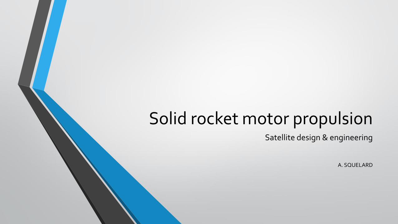
Propulsion basics
Solid Rocket Motors Propulsion - ULg - 04.12.2019 2
Principles of propulsion
Solid Rocket Motors Propulsion - ULg - 04.12.2019 3
A reaction force (thrust) is created by the ejection of gas.
F ≈ q . Ve
The thrust created by a balloon is clearly not sufficient !Let’s try to improve this technology !Furthermore, the pressure in the balloon drops quickly ! We must find a way to maintain the pressure inside the motor.We need to increase q and Ve
To do that, the best solution is to use a controllable exothermic chemical reaction that transforms a liquid or a solid into a gas at high temperature : the commonest one is : combustion, but there are other solutions !
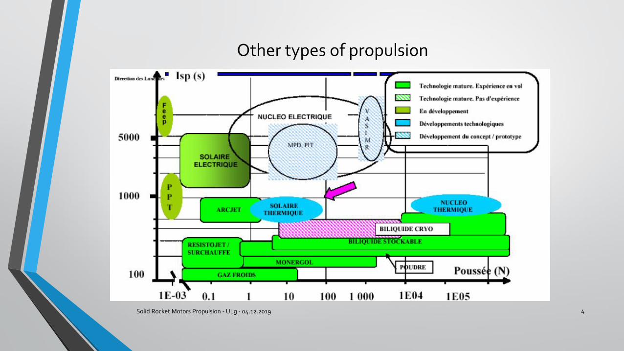
Other types of propulsion
Solid Rocket Motors Propulsion - ULg - 04.12.2019 4
Liquid or solid propulsion
Solid Rocket Motors Propulsion - ULg - 04.12.2019 5
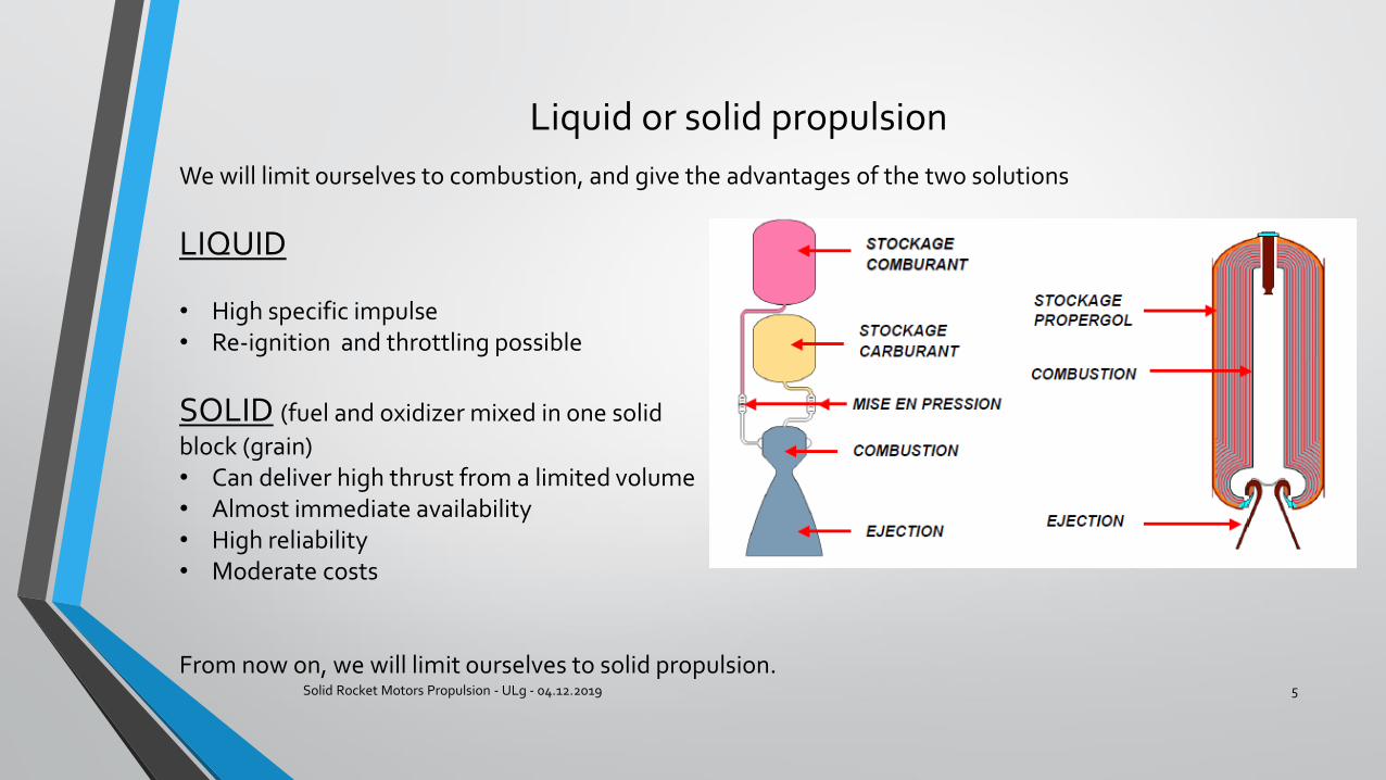
We will limit ourselves to combustion, and give the advantages of the two solutions
LIQUID
• High specific impulse• Re-ignition and throttling possible
SOLID (fuel and oxidizer mixed in one solid
block (grain)• Can deliver high thrust from a limited volume• Almost immediate availability • High reliability • Moderate costs
From now on, we will limit ourselves to solid propulsion.
Solid propulsion
Solid Rocket Motors Propulsion - ULg - 04.12.2019 6
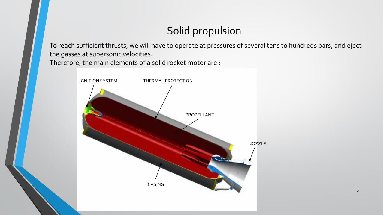
To reach sufficient thrusts, we will have to operate at pressures of several tens to hundreds bars, and eject the gasses at supersonic velocities.Therefore, the main elements of a solid rocket motor are :
CASING
PROPELLANT
NOZZLE
IGNITION SYSTEM THERMAL PROTECTION
History and applications
Solid Rocket Motors Propulsion - ULg - 04.12.2019 7
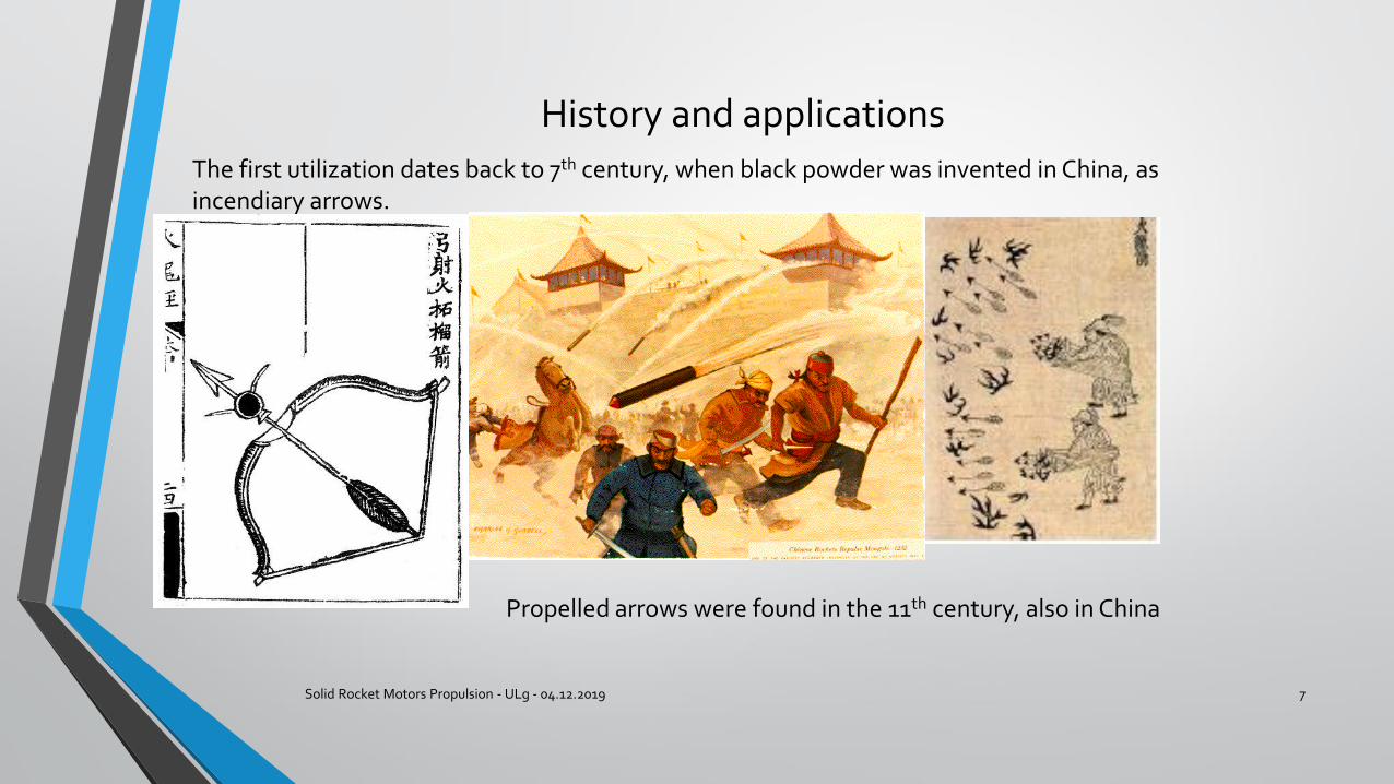
The first utilization dates back to 7th century, when black powder was invented in China, as incendiary arrows.
Propelled arrows were found in the 11th century, also in China
History (2)
Solid Rocket Motors Propulsion - ULg - 04.12.2019 8
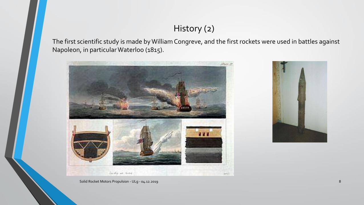
The first scientific study is made by William Congreve, and the first rockets were used in battles against Napoleon, in particular Waterloo (1815).
History and applications
Solid Rocket Motors Propulsion - ULg - 04.12.2019 9
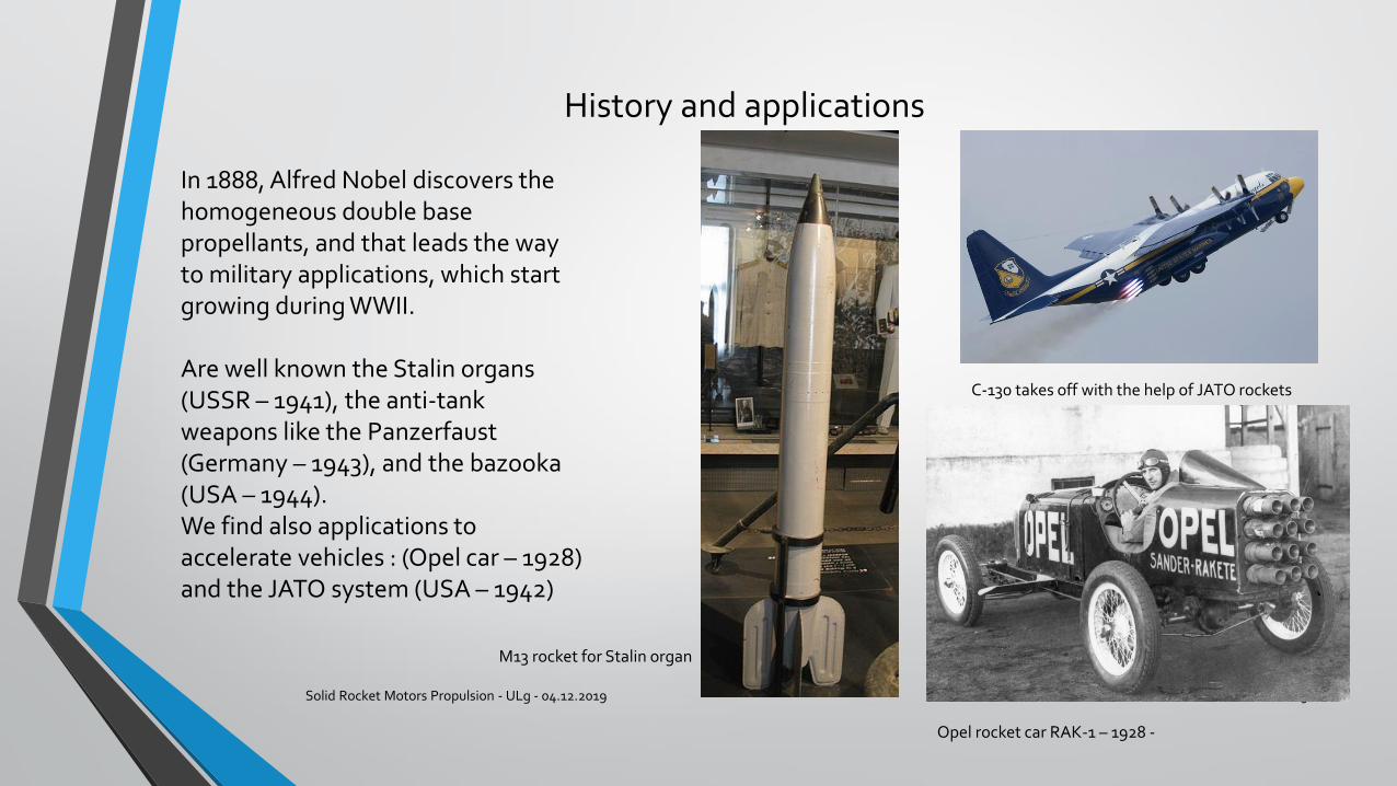
M13 rocket for Stalin organ
C-130 takes off with the help of JATO rockets
Opel rocket car RAK-1 – 1928 -
In 1888, Alfred Nobel discovers the homogeneous double base propellants, and that leads the way to military applications, which start growing during WWII.
Are well known the Stalin organs (USSR – 1941), the anti-tank weapons like the Panzerfaust (Germany – 1943), and the bazooka (USA – 1944).We find also applications to accelerate vehicles : (Opel car – 1928) and the JATO system (USA – 1942)

Modern applications : military
Solid Rocket Motors Propulsion - ULg - 04.12.2019 10
Missiles
Strategic – ICBM Trident D2 (US) Tactical – air-to-air MICA (France) Tactical : anti-tank LAHAT (Israel)
Boosters for missiles
Tomahawk cruise missile (US)
Modern applications : civilian
Solid Rocket Motors Propulsion - ULg - 04.12.2019 11
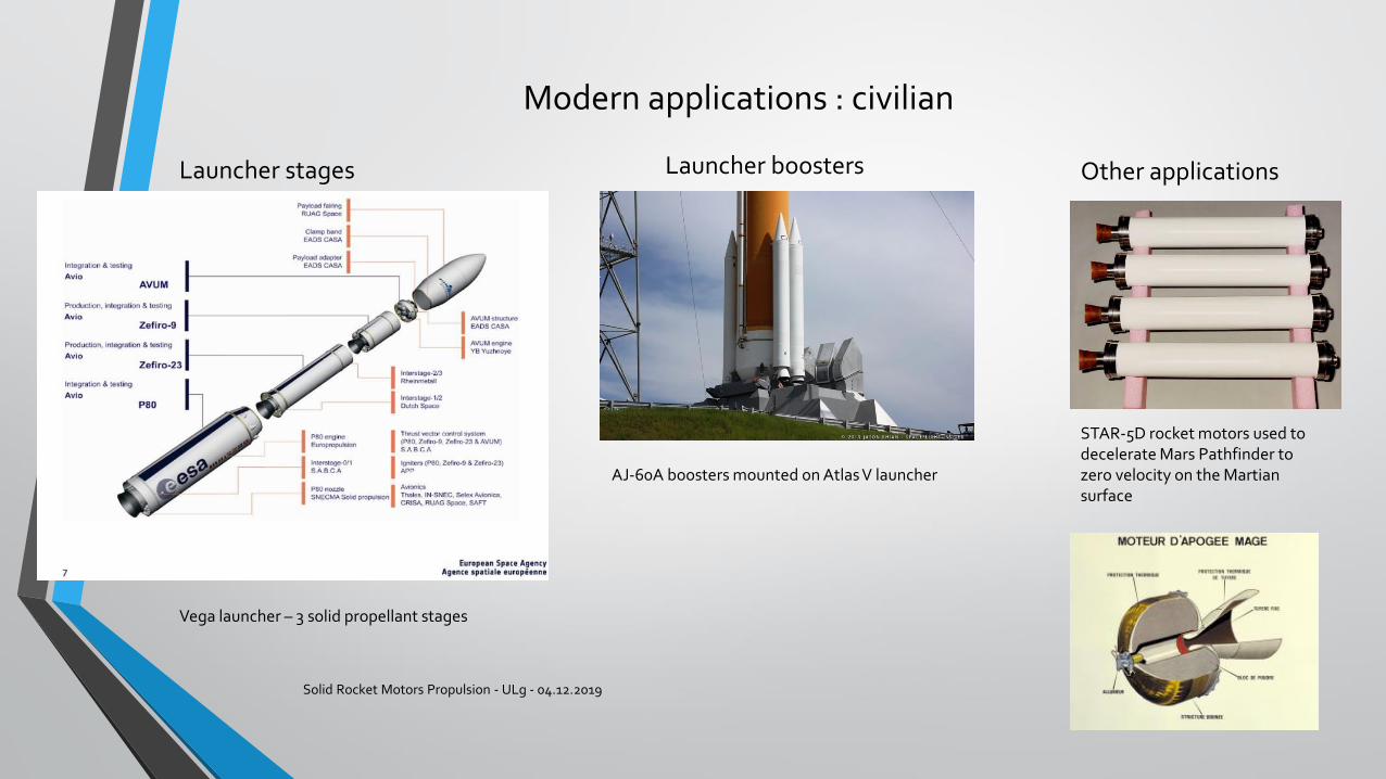
Launcher stages
Vega launcher – 3 solid propellant stages
Launcher boosters
AJ-60A boosters mounted on Atlas V launcher
Other applications
STAR-5D rocket motors used to decelerate Mars Pathfinder to zero velocity on the Martiansurface
The propellant grain
Solid Rocket Motors Propulsion - ULg - 04.12.2019 12
We have to define two parameters : composition and shape : these will define the performance and the thrust law of our motor.
COMPOSITION
History :
The first propellant was black powder (mixture of sulfur, charcoal and saltpeter [KNO3]). Inefficient as propellant.
From end of XIX° century : homogeneous double base propellants : mixture of nitrocellulose and nitroglycerine. Still in use today (smokeless), but not able to be used in large motors (tens to hundreds of tons.
Composite propellants
Solid Rocket Motors Propulsion - ULg - 04.12.2019 13
Criteria of choice :
Energetic performances (high reaction temperature)Kinetic performances (combustion velocity)Mechanical behavior (resistance to loads)Safety and vulnerability (resistance to unwanted ignition)Resistance to ageing (life duration in storage)Cost in productionInterface specifications
I will present here the composition that all the above requirements, and is used on all space launchers : • Ammonium perchlorate (oxidizer) (70 %)• Aluminum powder (fuel) (15 %)• Polybutadiene matrix (binder and fuel) (12%)
Composite propellants
Solid Rocket Motors Propulsion - ULg - 04.12.2019 14
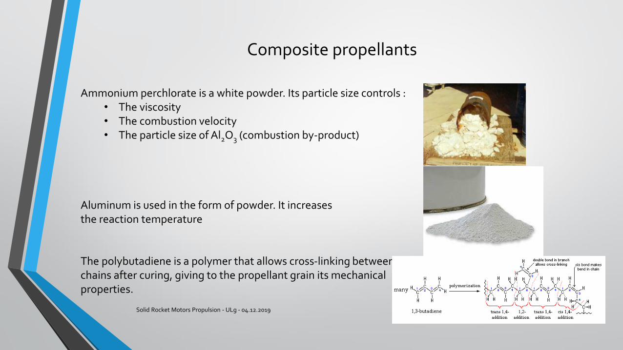
Ammonium perchlorate is a white powder. Its particle size controls :• The viscosity• The combustion velocity• The particle size of Al2O3 (combustion by-product)
Aluminum is used in the form of powder. It increases the reaction temperature
The polybutadiene is a polymer that allows cross-linking betweenchains after curing, giving to the propellant grain its mechanicalproperties.
The propellant grain
Solid Rocket Motors Propulsion - ULg - 04.12.2019 15
After ignition, the burning reaction takes place on the free surface of the propellant.The mass flow, and consequently the thrust generated by a propellant grain is proportional to the combustion surface at any moment of its operation.Assuming that the combustion velocity is the same in all directions, the combustion proceeds in parallel layers.Therefore, the thrust depends on the motor and the propellant grain geometries.This initial geometry is the only way to control the thrust law of a solid rocket motor.There are many geometries according to the required thrust law
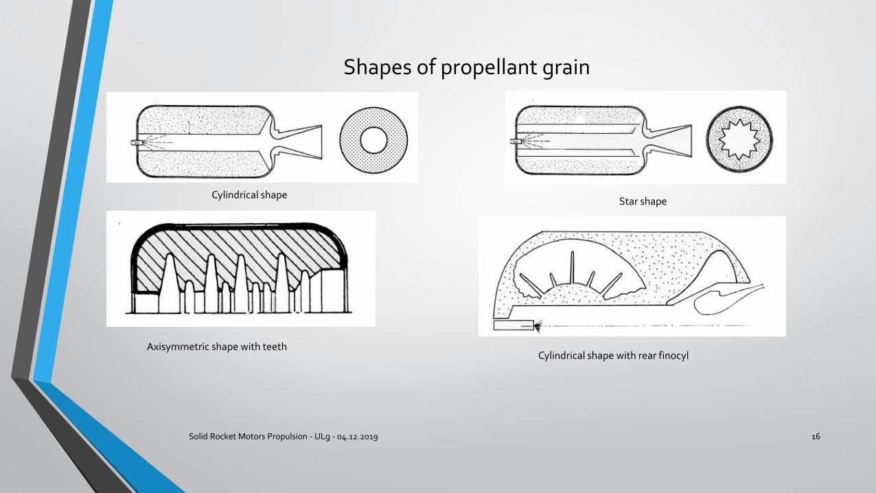
Shapes of propellant grain
Solid Rocket Motors Propulsion - ULg - 04.12.2019 16
Cylindrical shapeStar shape
Axisymmetric shape with teethCylindrical shape with rear finocyl
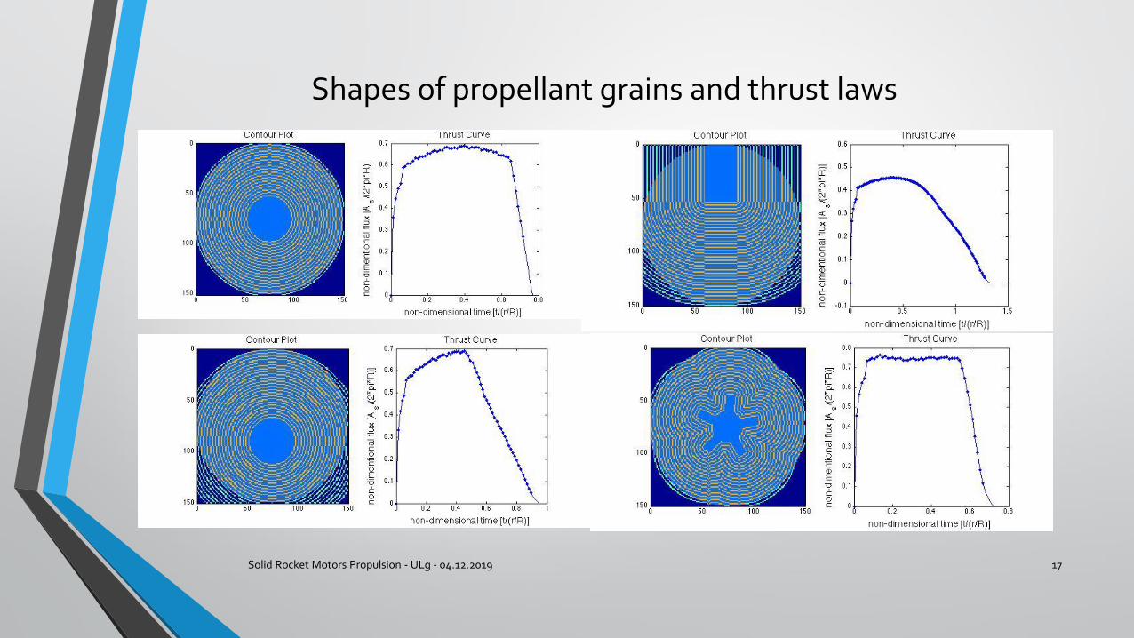
Shapes of propellant grains and thrust laws
Solid Rocket Motors Propulsion - ULg - 04.12.2019 17
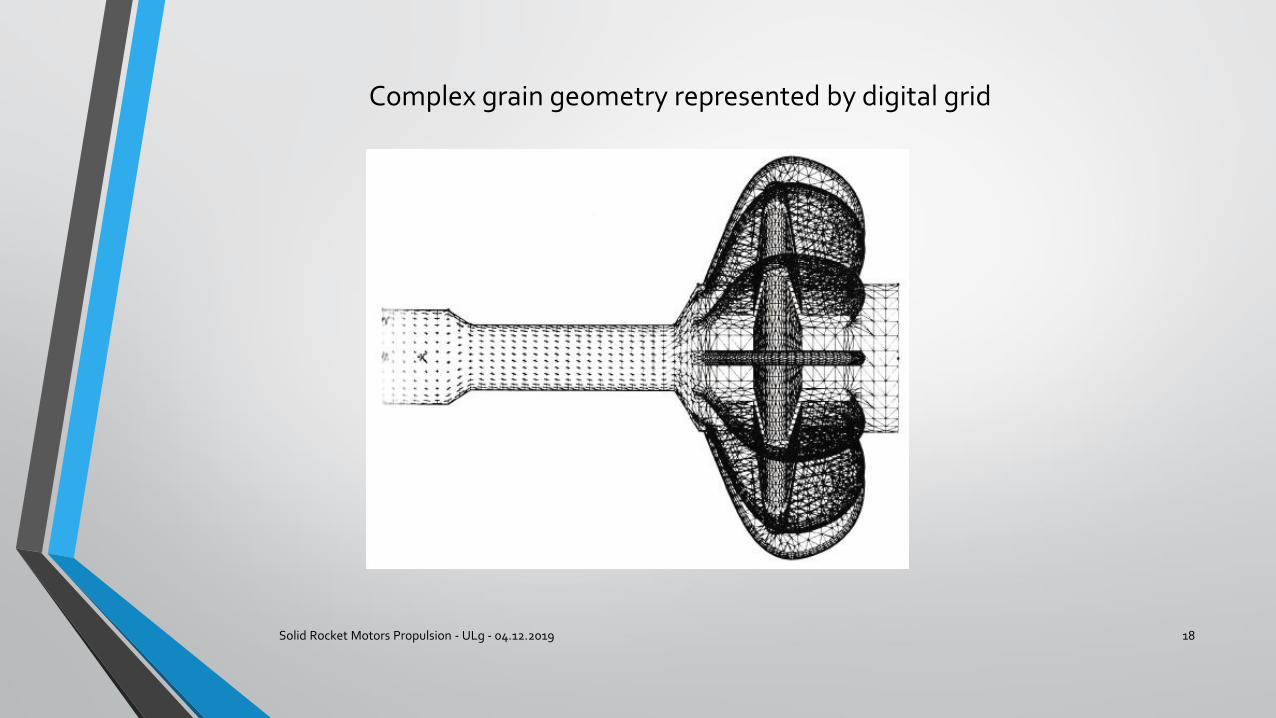
Complex grain geometry represented by digital grid
Solid Rocket Motors Propulsion - ULg - 04.12.2019 18
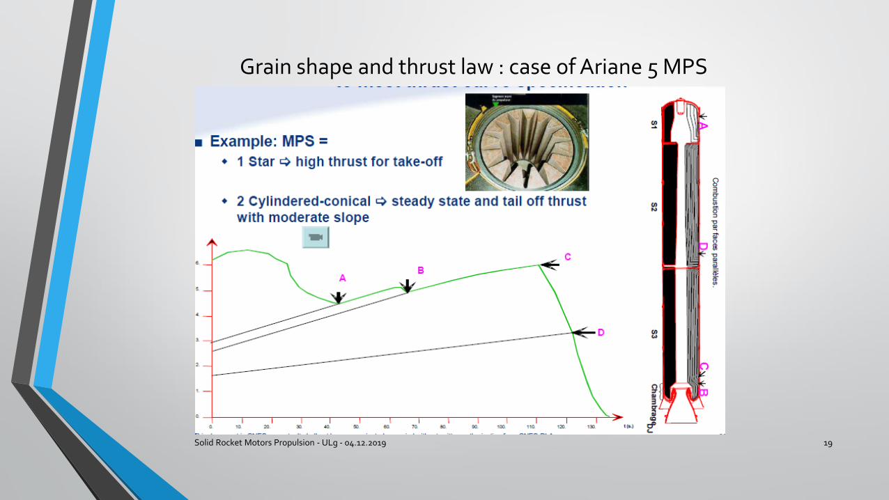
Grain shape and thrust law : case of Ariane 5 MPS
Solid Rocket Motors Propulsion - ULg - 04.12.2019 19
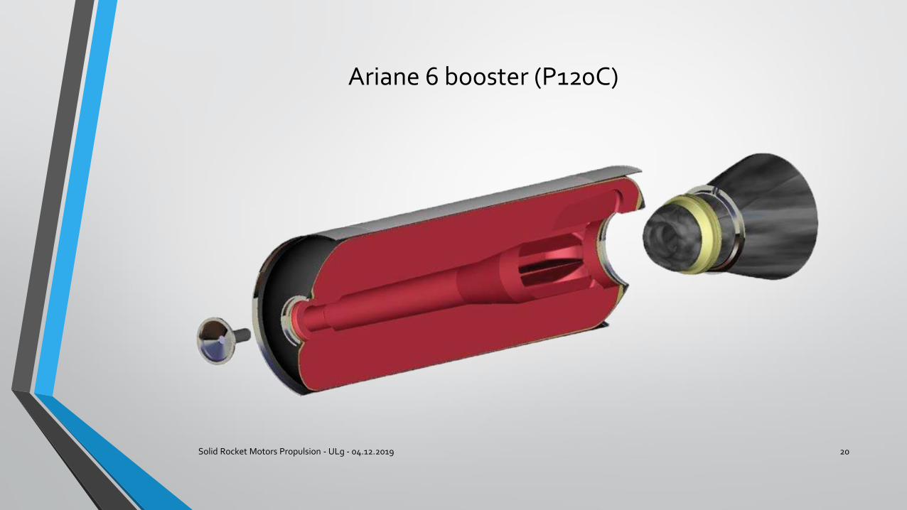
Ariane 6 booster (P120C)
Solid Rocket Motors Propulsion - ULg - 04.12.2019 20
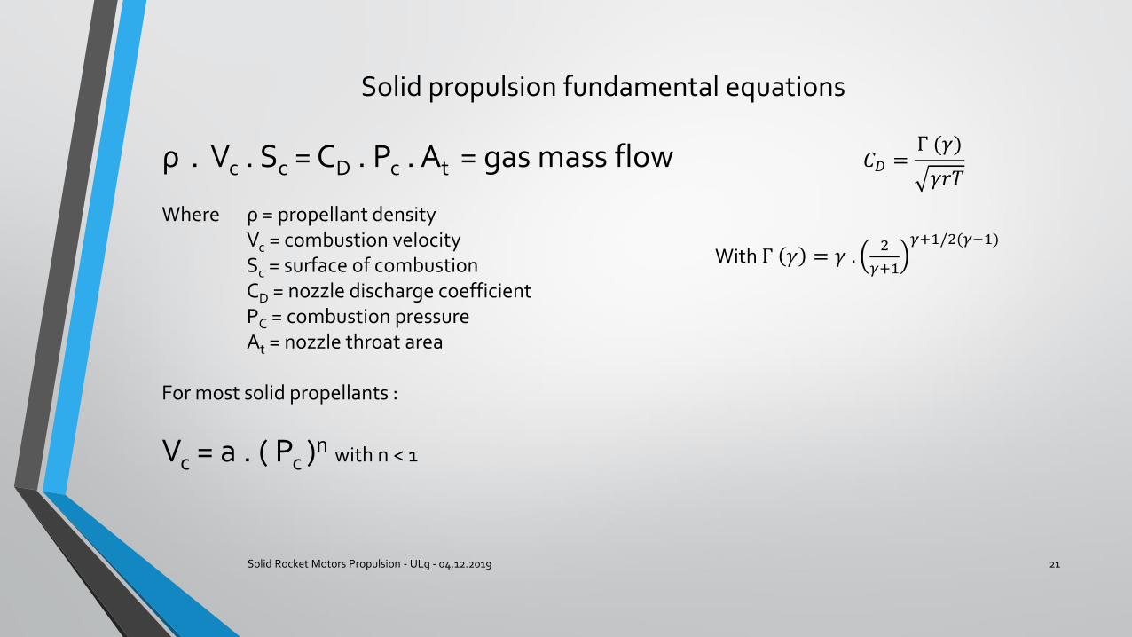
Solid propulsion fundamental equations
Solid Rocket Motors Propulsion - ULg - 04.12.2019 21
ρ . Vc . Sc = CD . Pc . At = gas mass flow
Where ρ = propellant densityVc = combustion velocitySc = surface of combustionCD = nozzle discharge coefficientPC = combustion pressureAt = nozzle throat area
For most solid propellants :
Vc = a . ( Pc )n with n < 1
𝐶𝐷 =Γ (𝛾)
𝛾𝑟𝑇
With Γ 𝛾 = 𝛾 .2
𝛾+1
𝛾+1/2(𝛾−1)
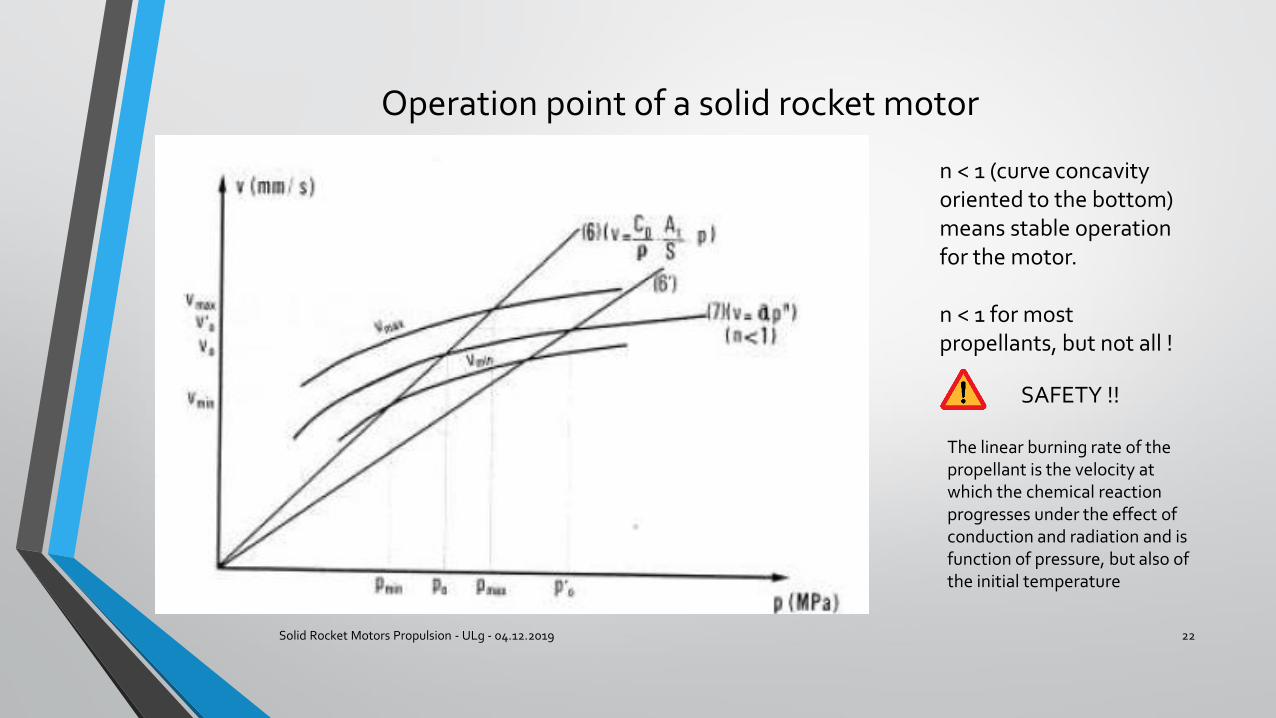
Operation point of a solid rocket motor
Solid Rocket Motors Propulsion - ULg - 04.12.2019 22
n < 1 (curve concavity oriented to the bottom) means stable operation for the motor.
n < 1 for most propellants, but not all !
SAFETY !!
The linear burning rate of the propellant is the velocity at which the chemical reaction progresses under the effect of conduction and radiation and is function of pressure, but also of the initial temperature
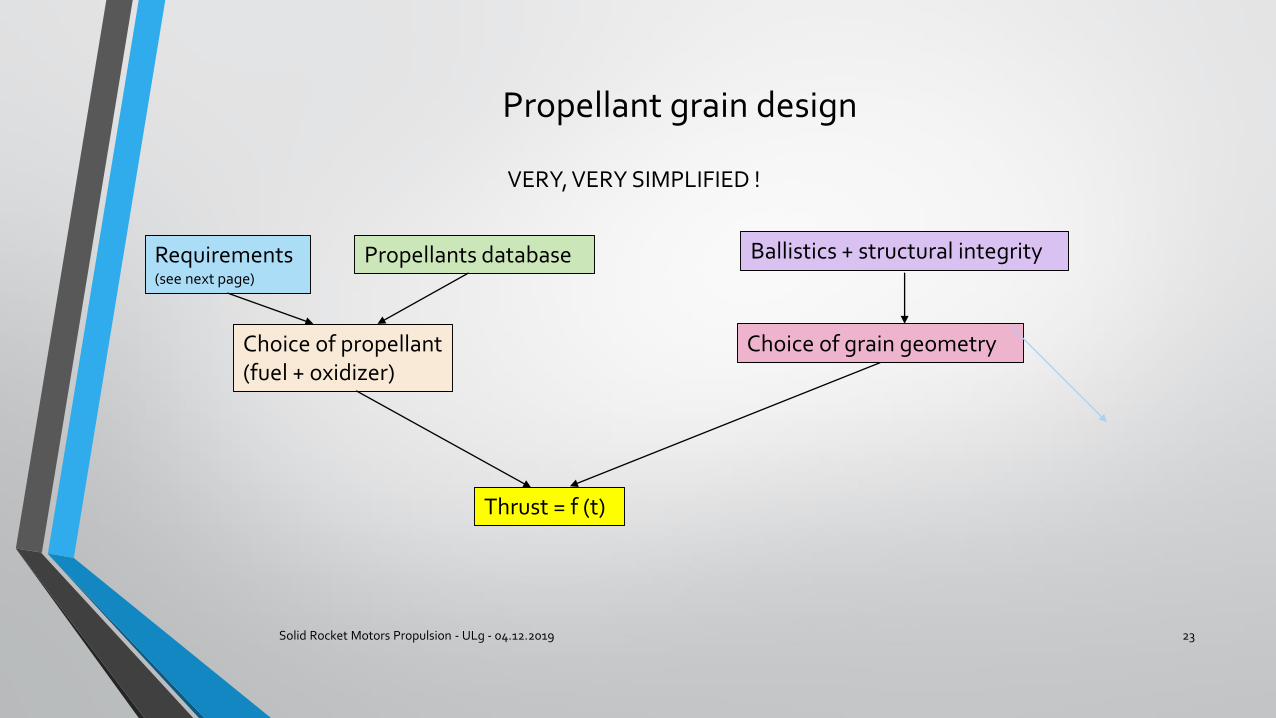
Propellant grain design
Solid Rocket Motors Propulsion - ULg - 04.12.2019 23
VERY, VERY SIMPLIFIED !
Choice of propellant (fuel + oxidizer)
Requirements(see next page)
Propellants database Ballistics + structural integrity
Choice of grain geometry
Thrust = f (t)
Requirements for propellant design
Solid Rocket Motors Propulsion - ULg - 04.12.2019 24
• Energy performance : Isp , Tc , density• Kinetic performances : maximum pressure, overall dimensions, weight• Resistance to loads : shrinkage during curing, long-term storage, thermal
cycles, firing• Safety : resistance to mechanical or electrical aggression• Resistance to ageing• Compliance with interface specifications• Production cost
Main steps to manufacture a propellant grain
Solid Rocket Motors Propulsion - ULg - 04.12.2019 25
Perchlorate manufacturing with particles size control
Pre-mixing of polybutadiene with aluminum powder and additives*
Mixing
Vacuum casting
Curingfew days at 60°C
Controls : propellant integrity through X-ray inspections, ballistic data and mechanical characteristics through samples
Additives :
• Burning rate modifiers (Fe2 O3)
• Surface agents• Catalysts• Anti-oxidants
Thermal protections
Solid Rocket Motors Propulsion - ULg - 04.12.2019 26
• Protects the casing from combustion gas when propellant has completely burned• Inhibits the combustion where it is not needed (on Ariane MPS : frontal PT)• Controls the loads due to propellant shrinkage when curing• Made of rubber + additives
Thermal protections
Solid Rocket Motors Propulsion - ULg - 04.12.2019 27
Thermal protections installation
Solid Rocket Motors Propulsion - ULg - 04.12.2019 28
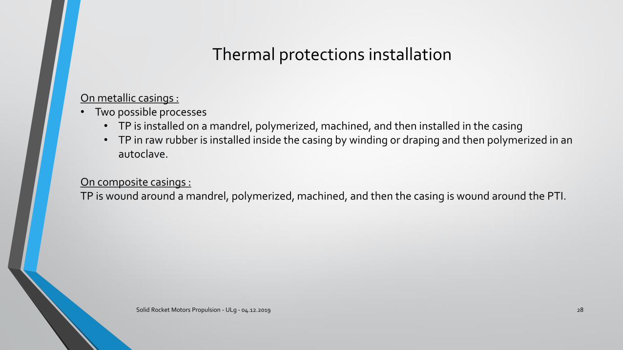
On metallic casings : • Two possible processes
• TP is installed on a mandrel, polymerized, machined, and then installed in the casing• TP in raw rubber is installed inside the casing by winding or draping and then polymerized in an
autoclave.
On composite casings :TP is wound around a mandrel, polymerized, machined, and then the casing is wound around the PTI.
Thermal protections installation
Solid Rocket Motors Propulsion - ULg - 04.12.2019 29
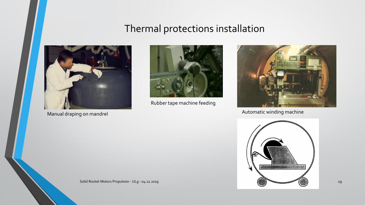
Manual draping on mandrel
Rubber tape machine feeding
Automatic winding machine
Casings (structures)
Solid Rocket Motors Propulsion - ULg - 04.12.2019 30
Two types of casings :
Metallic : steel or aluminum
Composite : carbon, glass or Kevlar fibers embedded in resin (epoxy)
The criteria of choice are :
• Production costs (raw materials, machines, control equipment, manufacturing difficultness)• Performance (weight / allowable stress)• Resistance to environment (heat, mechanical or chemical aggression)• Other constraints (interfaces)
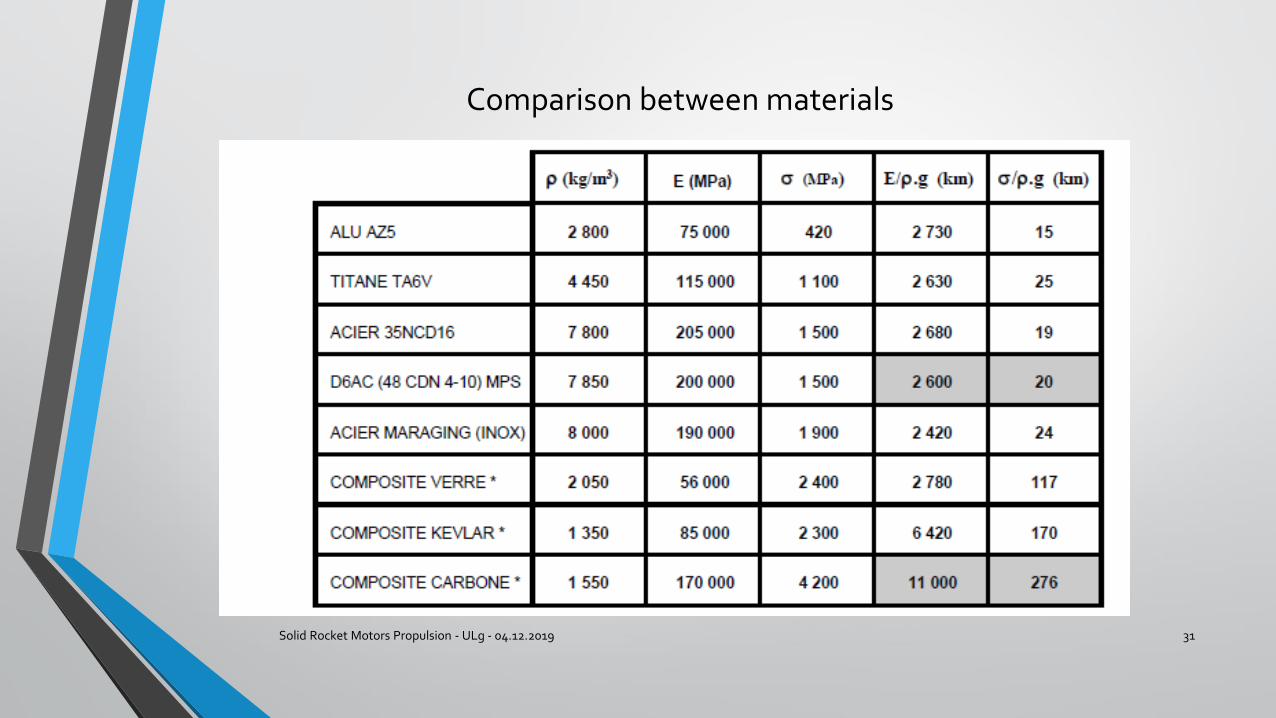
Comparison between materials
Solid Rocket Motors Propulsion - ULg - 04.12.2019 31
Metallic casings
Solid Rocket Motors Propulsion - ULg - 04.12.2019 32
Example : MPS of Ariane 5
Material : Steel D6AC Domes : disk formed in shape of domes
Cylinders : from preforms flow-forming into cylinders, then heat treatment and welding of three cylinders
Composite casings
Solid Rocket Motors Propulsion - ULg - 04.12.2019 33
Carbon fiber
Pre-impregnated fibers
Winding on TP
Polymerization in autoclave
Mandrel removal and final machining
OR
Composite casings
Solid Rocket Motors Propulsion - ULg - 04.12.2019 34
There are essentially two types of winding : polar and hoop
P80 (1st stage of VEGA) winding
Composite casings
Solid Rocket Motors Propulsion - ULg - 04.12.2019 35
Finished P80 composite casing Finished Pathfinder booster segment (Prototype for SLS booster)
Booster segments
Solid Rocket Motors Propulsion - ULg - 04.12.2019 36
• For space launchers, the propellant grains are manufactured in several segments.
• To cast a booster grain in one piece would require huge installations for casting, handling and transportation.
• However, progress is made, and newer boosters stages are manufactured in one segment.
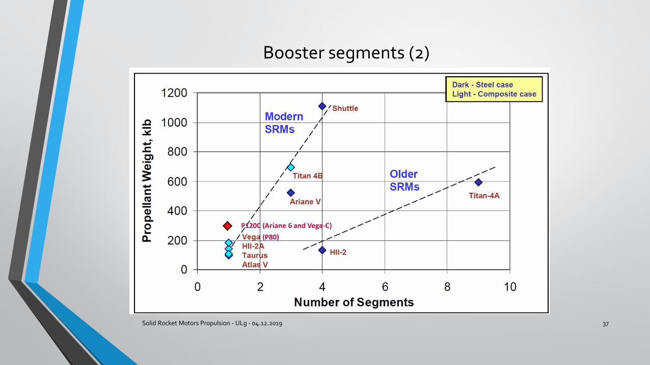
Booster segments (2)
Solid Rocket Motors Propulsion - ULg - 04.12.2019 37
Joints
Solid Rocket Motors Propulsion - ULg - 04.12.2019 38
The joints between the segments are critical for safety. Any hot gas leak to the outside of the booster can have catastrophic consequences
Casing tightness is made by redundant o-rings
Thermal protection tightness is made by a labyrinth geometry filled with grease. No flow → the gasses cool rapidly.
Problem : the casing inflates when the inside pressure increases and the geometry around the o-rings changes : the pressure has to close gaps and not open them.
Joints (2)
Solid Rocket Motors Propulsion - ULg - 04.12.2019 39
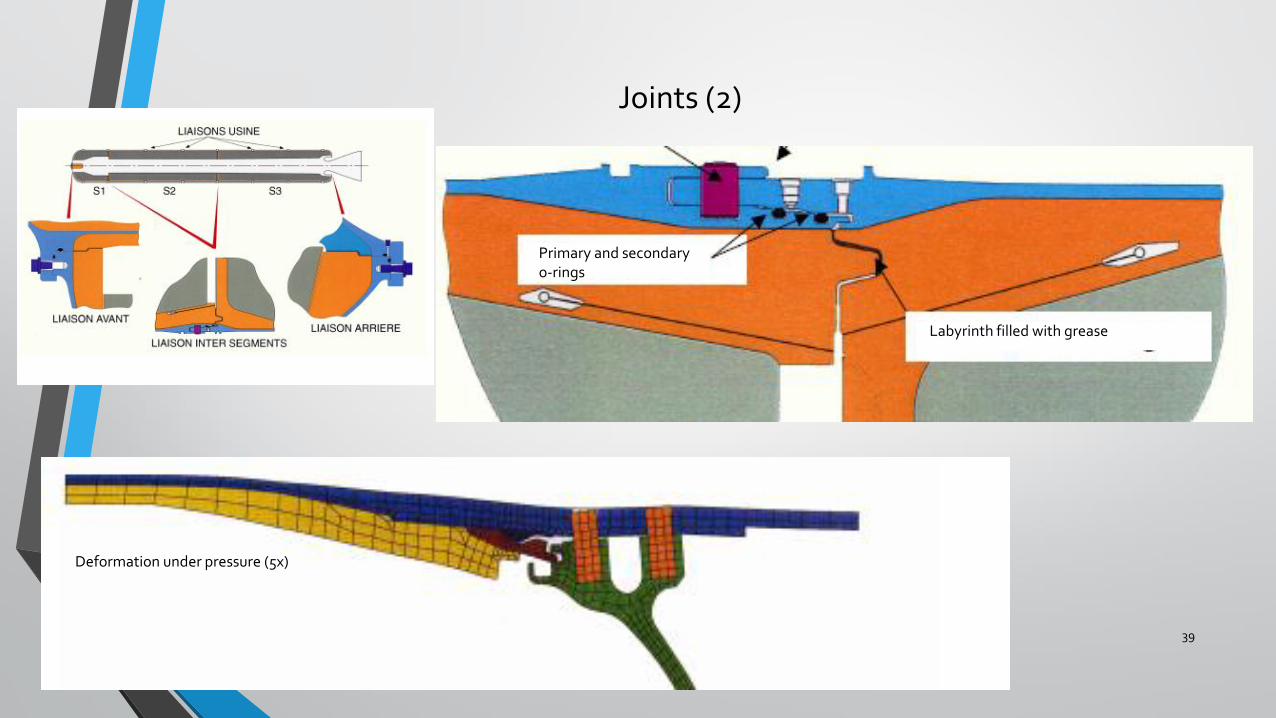
Deformation under pressure (5x)
Primary and secondary o-rings
Labyrinth filled with grease
The Challenger Space Shuttle accident
Solid Rocket Motors Propulsion - ULg - 04.12.2019 40
Description
The Challenger Space Shuttle accident
Solid Rocket Motors Propulsion - ULg - 04.12.2019 41
The technical cause
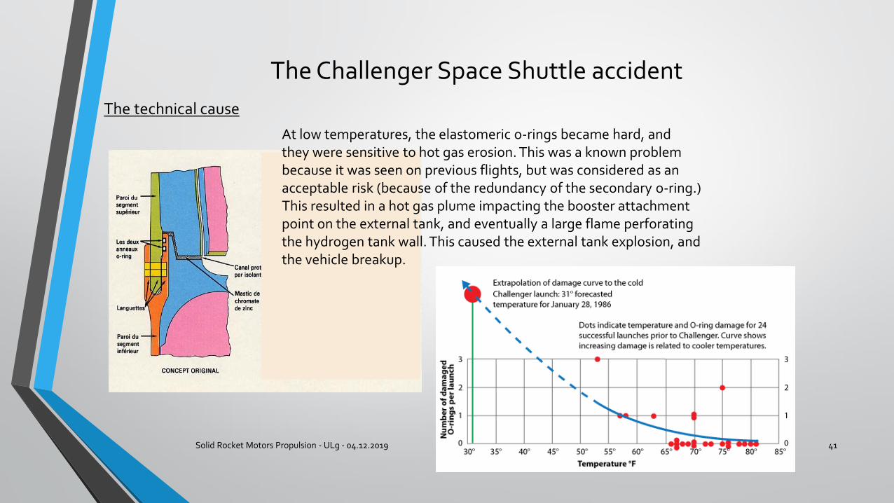
At low temperatures, the elastomeric o-rings became hard, and they were sensitive to hot gas erosion. This was a known problem because it was seen on previous flights, but was considered as an acceptable risk (because of the redundancy of the secondary o-ring.)This resulted in a hot gas plume impacting the booster attachment point on the external tank, and eventually a large flame perforating the hydrogen tank wall. This caused the external tank explosion, and the vehicle breakup.
The Challenger Space Shuttle accident
Solid Rocket Motors Propulsion - ULg - 04.12.2019 42
The organizational causes
Reference : “The Challenger Launch Decision” by Diane Vaughan
1. Normalization of deviance : increase of “acceptable risk” criteria : several observations of eroded o-rings became more and more acceptable, and the argument of the redundancy of the secondary O-ring was more and more used, but wrong.
2. Culture of production : initially, NASA was managed by technicians, but it became more complex and bureaucratic, and the budgetary constraints transformed the organization into a production organization, with the objective to recommend launch in all cases.
3. Secrecy of information : the way information circulates, the processes, and the structure of regulatory relations have as a result that the information available to the top managers is filtered, and technical details, considered by engineers as “acceptable risk” were not clearly presented.

The Challenger Space Shuttle accident
Solid Rocket Motors Propulsion - ULg - 04.12.2019 43
The lessons
1. The assessment of risks may not rely upon routine evaluations. In a production process, you may not use the argument “This has been already accepted” because other influential factors, or the environment, may have changed.
2. The budget scarcities, or the delay constraints, or the bureaucratic organization may not change the risk evaluation or let you use a limited rationale, not taking into account all the contributing factors.
3. The way information is relayed to top decision makers, and the way this information is presented (this is particularly true for statistics) must be carefully crafted, and must not deform the engineering reality.
The nozzle (theory)
Solid Rocket Motors Propulsion - ULg - 04.12.2019 44
Objective : to transform thermal energy of the gasses into kinetic energy.
Modelling of nozzle operation needs several simplifying assumptions : • Combustion and expansion are two separate phenomena happening respectively in the
combustion chamber and the nozzle.• The expansion in the nozzle is isentropic• The flow is one-dimensional.• The gas kinetic energy at the entrance of the nozzle is negligible.• The gas flow occurs without separating from the nozzle wall.• The combustion gas is a perfect gas, and its molecular weight and are constant.
Nozzle theory (2)
Solid Rocket Motors Propulsion - ULg - 04.12.2019 45
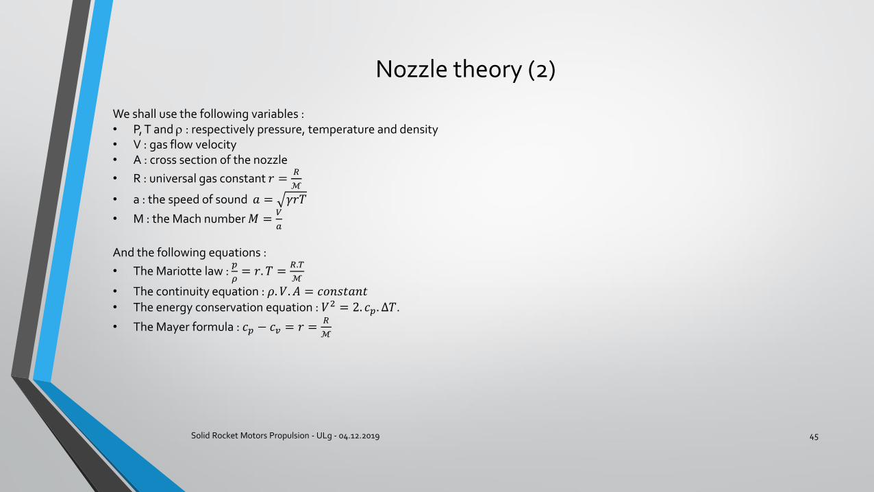
We shall use the following variables :• P, T and : respectively pressure, temperature and density• V : gas flow velocity• A : cross section of the nozzle
• R : universal gas constant 𝑟 =𝑅
ℳ
• a : the speed of sound 𝑎 = 𝛾𝑟𝑇
• M : the Mach number 𝑀 =𝑉
𝑎
And the following equations :
• The Mariotte law : 𝑝
𝜌= 𝑟. 𝑇 =
𝑅.𝑇
ℳ
• The continuity equation : 𝜌. 𝑉. 𝐴 = 𝑐𝑜𝑛𝑠𝑡𝑎𝑛𝑡• The energy conservation equation : 𝑉2 = 2. 𝑐𝑝. Δ𝑇.
• The Mayer formula : 𝑐𝑝 − 𝑐𝑣 = 𝑟 =𝑅
ℳ
The nozzle theory (3)
Solid Rocket Motors Propulsion - ULg - 04.12.2019 46
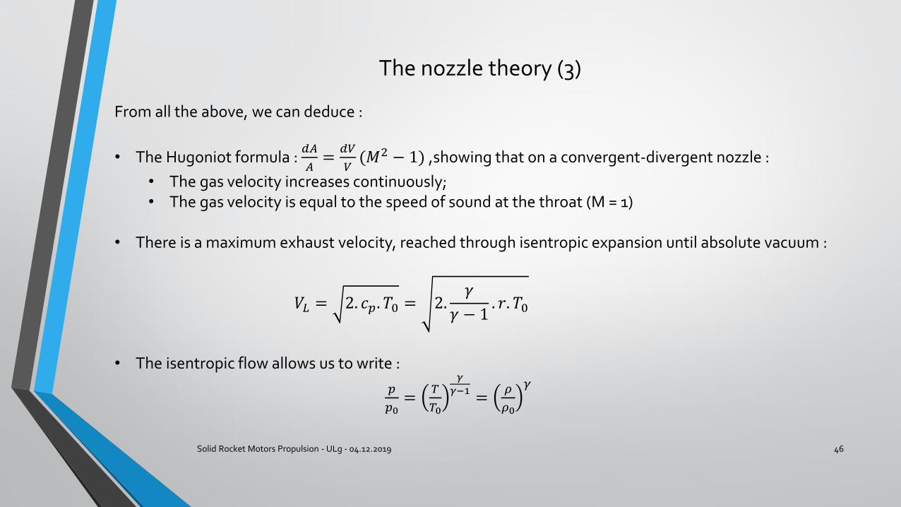
From all the above, we can deduce :
• The Hugoniot formula : 𝑑𝐴
𝐴=
𝑑𝑉
𝑉(𝑀2 − 1) ,showing that on a convergent-divergent nozzle :
• The gas velocity increases continuously;• The gas velocity is equal to the speed of sound at the throat (M = 1)
• There is a maximum exhaust velocity, reached through isentropic expansion until absolute vacuum :
𝑉𝐿 = 2. 𝑐𝑝. 𝑇0 = 2.𝛾
𝛾 − 1. 𝑟. 𝑇0
• The isentropic flow allows us to write :
𝑝
𝑝0=
𝑇
𝑇0
𝛾
𝛾−1=
𝜌
𝜌0
𝛾
The nozzle theory (4)
Solid Rocket Motors Propulsion - ULg - 04.12.2019 47
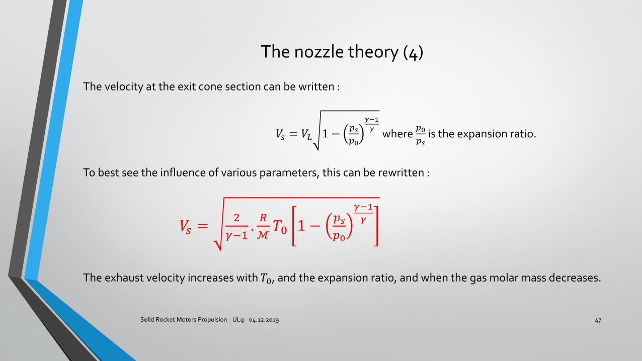
The velocity at the exit cone section can be written :
𝑉𝑠 = 𝑉𝐿 1 −𝑝𝑠
𝑝0
𝛾−1
𝛾where
𝑝0
𝑝𝑠is the expansion ratio.
To best see the influence of various parameters, this can be rewritten :
𝑉𝑠 =2
𝛾−1.𝑅
ℳ𝑇0 1 −
𝑝𝑠
𝑝0
𝛾−1
𝛾
The exhaust velocity increases with 𝑇0, and the expansion ratio, and when the gas molar mass decreases.
The nozzle – Example of Ariane 5 MPS
Solid Rocket Motors Propulsion - ULg - 04.12.2019 48
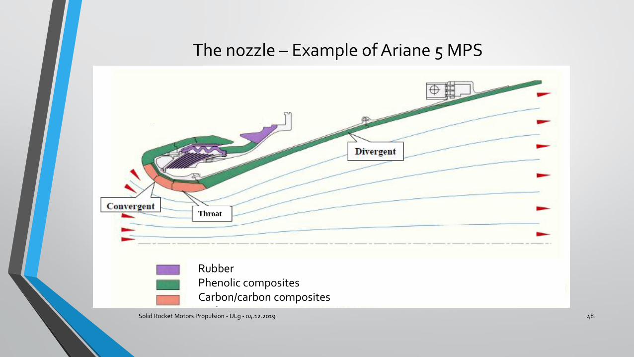
Throat
RubberPhenolic compositesCarbon/carbon composites
The nozzle : objectives
Solid Rocket Motors Propulsion - ULg - 04.12.2019 49
1. Transform the thermal energy into kinetic energy.2. Give a guidance capability by allowing movement of the nozzle
Some figures for MPS nozzle : • Mass : 6,1 tons• Throat diameter : 900 mm• Exit diameter : 2,9 m• Gimbal angle : 7,1°
The design of a nozzle is very difficult : use of FE thermomechanical model, with complex phenomena like ablation (material is stripped off through action of 3000 K gas at high velocity.) Also the characterization of complex materials like carbon/carbon composites at high temperatures is very difficult. And finally, the loads are difficult to evaluate, due to the very high temperature gradients through the nozzle wall.
The nozzle : operation
Solid Rocket Motors Propulsion - ULg - 04.12.2019 50
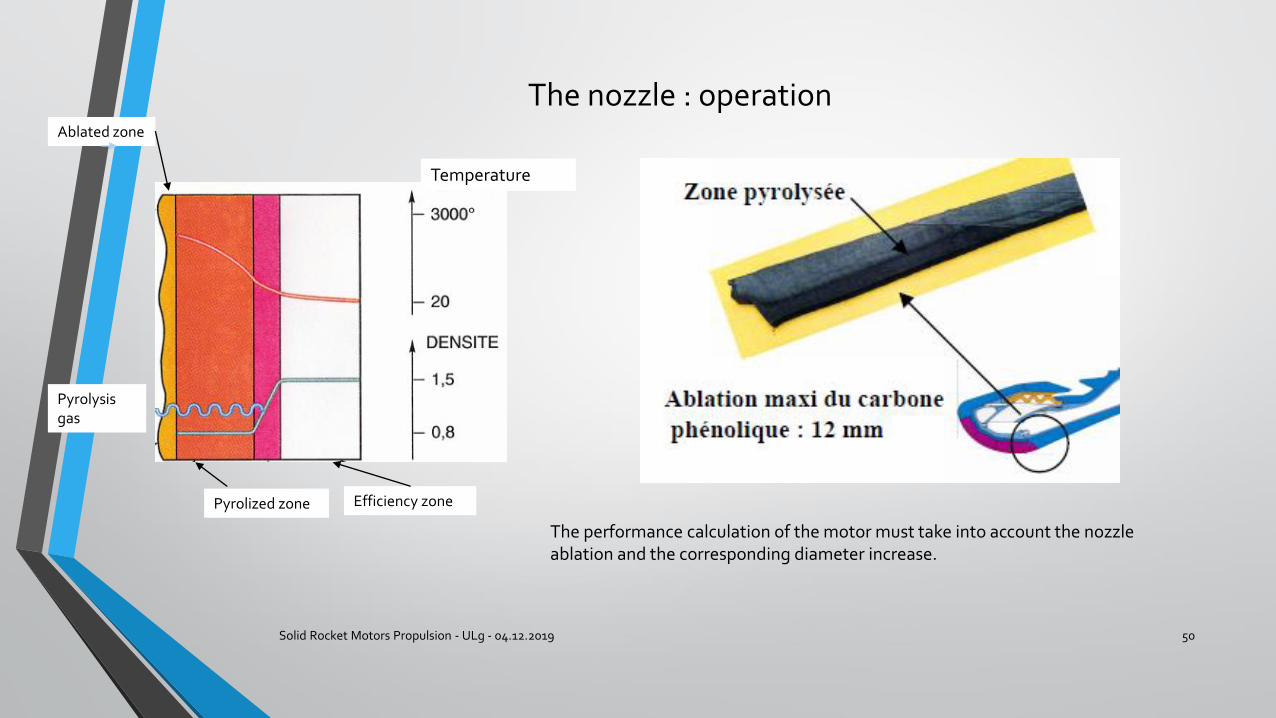
Temperature
Pyrolysis gas
Ablated zone
Pyrolized zone Efficiency zone
The performance calculation of the motor must take into account the nozzle ablation and the corresponding diameter increase.
Piloting a launcher through nozzle orientation
Solid Rocket Motors Propulsion - ULg - 04.12.2019 51
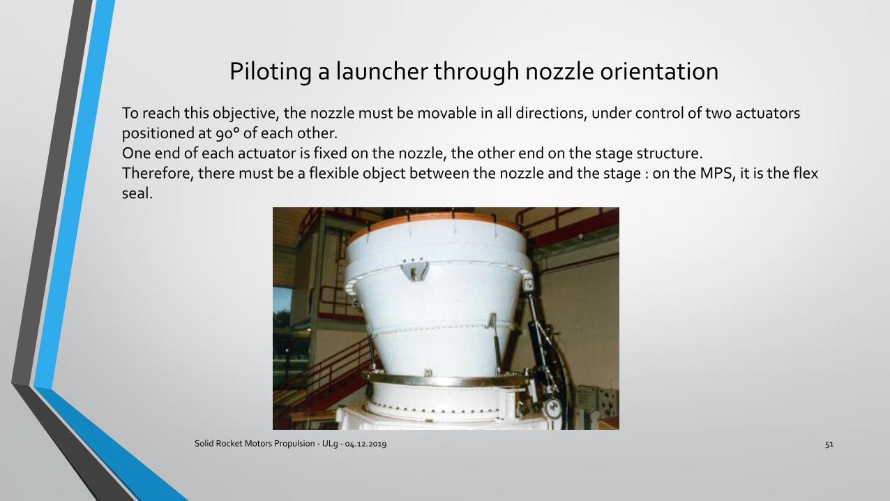
To reach this objective, the nozzle must be movable in all directions, under control of two actuators positioned at 90° of each other. One end of each actuator is fixed on the nozzle, the other end on the stage structure.Therefore, there must be a flexible object between the nozzle and the stage : on the MPS, it is the flex seal.
The flex seal
Solid Rocket Motors Propulsion - ULg - 04.12.2019 52
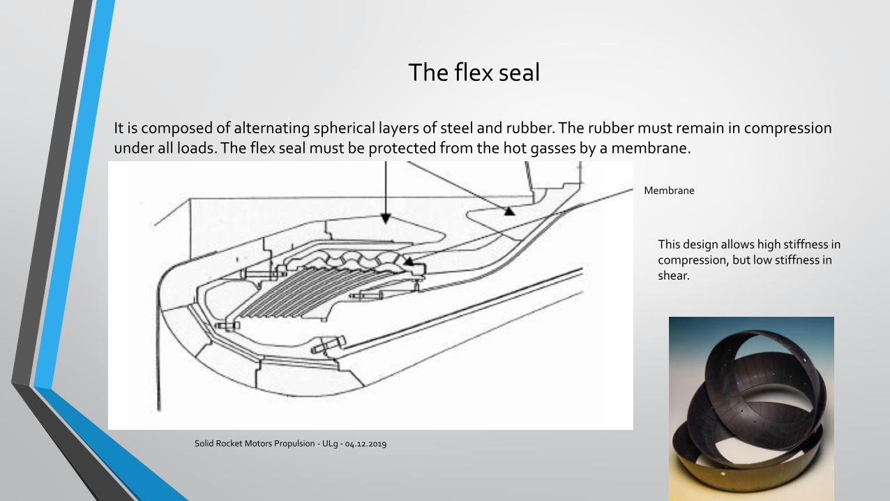
It is composed of alternating spherical layers of steel and rubber. The rubber must remain in compression under all loads. The flex seal must be protected from the hot gasses by a membrane.
Membrane
This design allows high stiffness in compression, but low stiffness in shear.
The ignition system
Solid Rocket Motors Propulsion - ULg - 04.12.2019 53
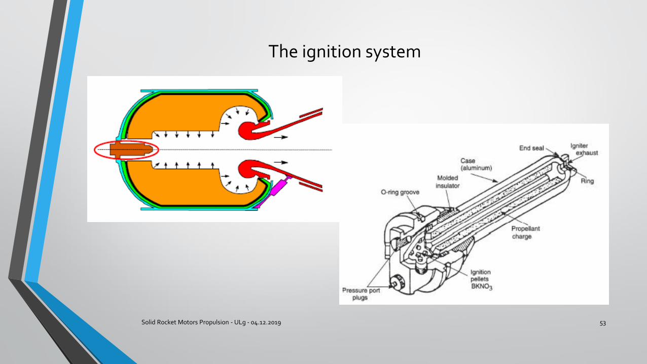
The ignition system
Solid Rocket Motors Propulsion - ULg - 04.12.2019 54
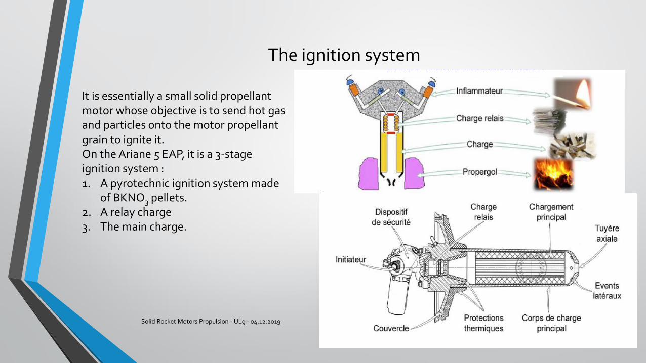
It is essentially a small solid propellant motor whose objective is to send hot gas and particles onto the motor propellant grain to ignite it.On the Ariane 5 EAP, it is a 3-stage ignition system : 1. A pyrotechnic ignition system made
of BKNO3 pellets.2. A relay charge3. The main charge.
Thrust oscillations
Solid Rocket Motors Propulsion - ULg - 04.12.2019 55
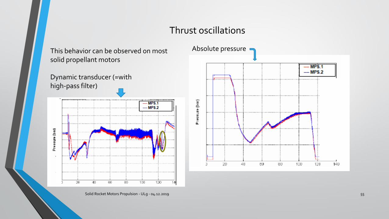
This behavior can be observed on most solid propellant motors
Absolute pressure
Dynamic transducer (=with high-pass filter)
Thrust oscillations
Solid Rocket Motors Propulsion - ULg - 04.12.2019 56
These oscillations are of a few tenths of % in pressure, but of few % in thrust. This amounts to several kN !The frequency of one of the modes can dangerously approach the structural resonant modes of the stage or the launcher, and possibly cause damage to the payloads !
This phenomenon has been actively investigated since the years 1970 : the origin is now understood : it comes from the interaction of vortices at the nozzle entrance and the acoustical cavity formed by the last segment of the booster.
The last segment is a hollow cylinder which has an acoustic longitudinal resonant frequency which varies slowly with time.
Vortices are created in the gas flow according to several phenomena.
Thrust oscillations
Solid Rocket Motors Propulsion - ULg - 04.12.2019 57
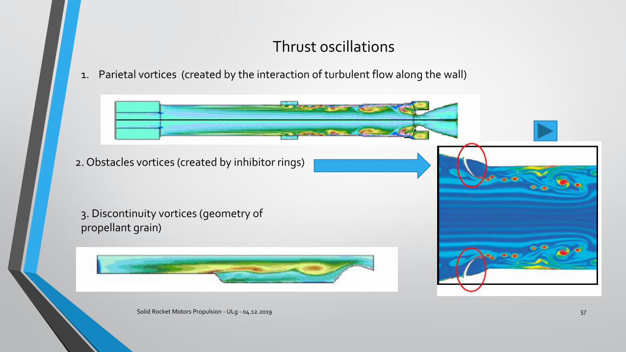
1. Parietal vortices (created by the interaction of turbulent flow along the wall)
2. Obstacles vortices (created by inhibitor rings)
3. Discontinuity vortices (geometry of propellant grain)
Thrust oscillations
Solid Rocket Motors Propulsion - ULg - 04.12.2019 58
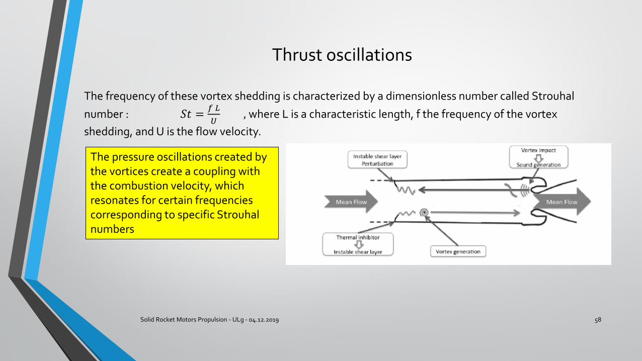
The frequency of these vortex shedding is characterized by a dimensionless number called Strouhal
number : 𝑆𝑡 =𝑓 𝐿
𝑈, where L is a characteristic length, f the frequency of the vortex
shedding, and U is the flow velocity.
The pressure oscillations created by the vortices create a coupling with the combustion velocity, which resonates for certain frequencies corresponding to specific Strouhalnumbers
Thrust oscillations
Solid Rocket Motors Propulsion - ULg - 04.12.2019 59
Solid propellant stage qualification
Solid Rocket Motors Propulsion - ULg - 04.12.2019 60
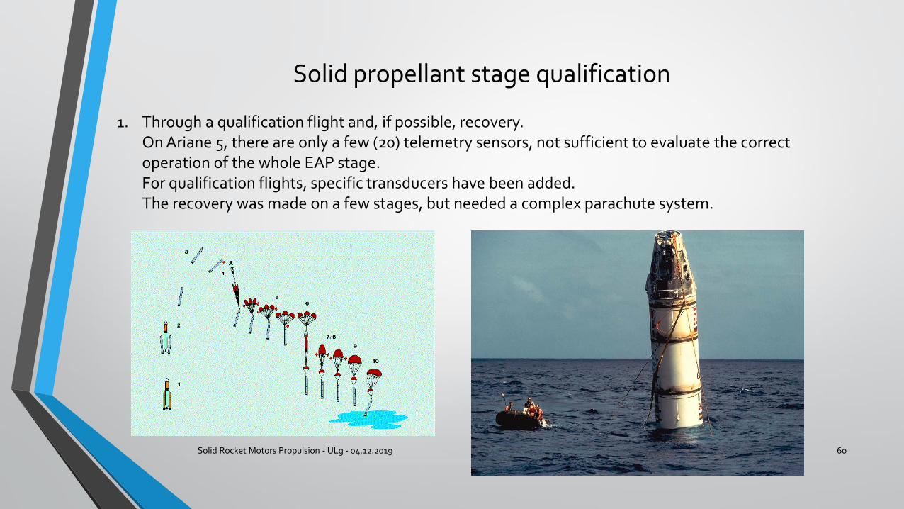
1. Through a qualification flight and, if possible, recovery.On Ariane 5, there are only a few (20) telemetry sensors, not sufficient to evaluate the correct operation of the whole EAP stage. For qualification flights, specific transducers have been added.The recovery was made on a few stages, but needed a complex parachute system.
Solid propellant stage qualification
Solid Rocket Motors Propulsion - ULg - 04.12.2019 61
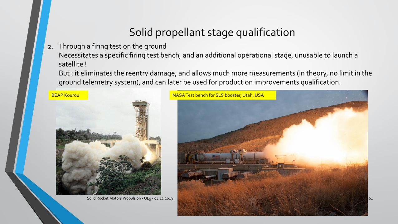
2. Through a firing test on the groundNecessitates a specific firing test bench, and an additional operational stage, unusable to launch a satellite !But : it eliminates the reentry damage, and allows much more measurements (in theory, no limit in the ground telemetry system), and can later be used for production improvements qualification.
BEAP Kourou NASA Test bench for SLS booster, Utah, USA
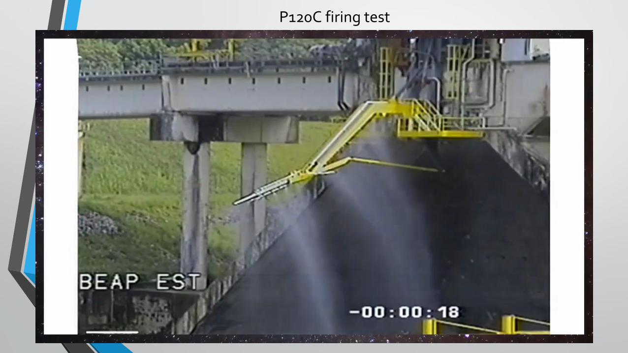
P120C firing test
Solid Rocket Motors Propulsion - ULg - 04.12.2019 62
Hybrid propulsion
Solid Rocket Motors Propulsion - ULg - 04.12.2019 63
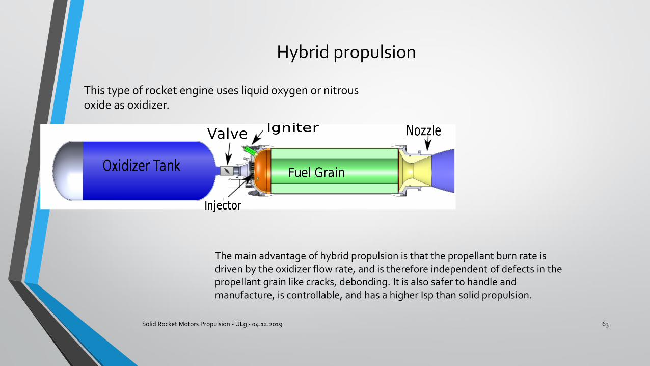
This type of rocket engine uses liquid oxygen or nitrous oxide as oxidizer.
The main advantage of hybrid propulsion is that the propellant burn rate is driven by the oxidizer flow rate, and is therefore independent of defects in the propellant grain like cracks, debonding. It is also safer to handle and manufacture, is controllable, and has a higher Isp than solid propulsion.
Hybrid propulsion
Solid Rocket Motors Propulsion - ULg - 04.12.2019 64
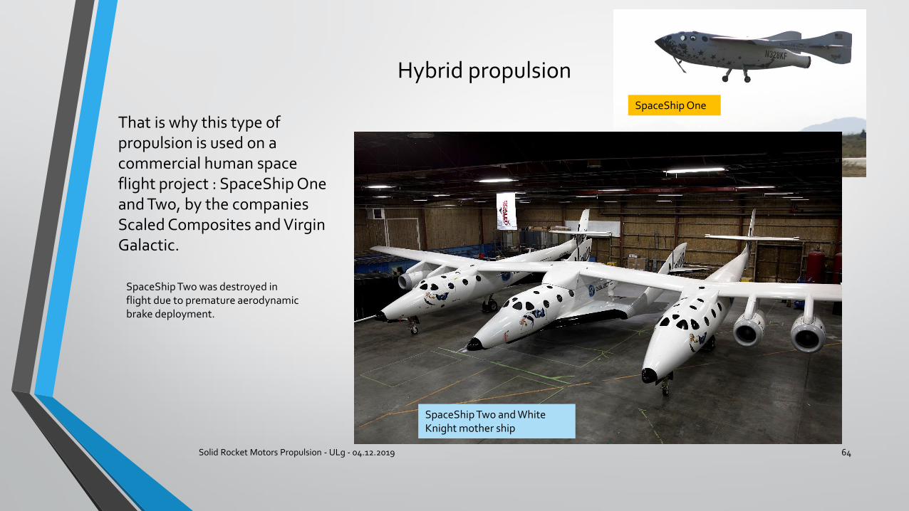
That is why this type of propulsion is used on a commercial human space flight project : SpaceShip One and Two, by the companies Scaled Composites and Virgin Galactic.
SpaceShip One
SpaceShip Two and White Knight mother ship
SpaceShip Two was destroyed in flight due to premature aerodynamic brake deployment.

Thank you for your attention !
Solid Rocket Motors Propulsion - ULg - 04.12.2019 65