
Solid-Dielectric, Independent Pole Option Recloser ... · • Works directly with SEL-651R, ABB...
12
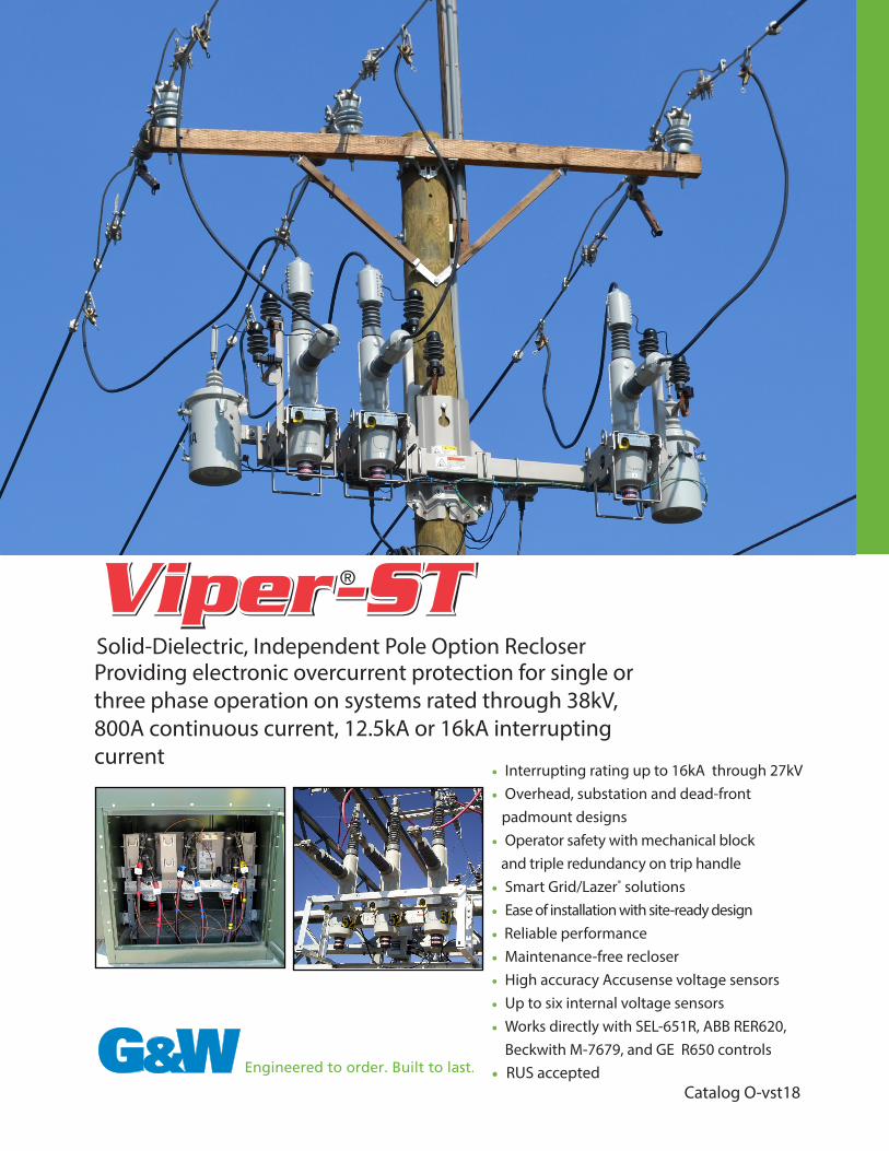
Solid-Dielectric, Independent Pole Option Recloser Providing electronic overcurrent protection for single or three phase operation on systems rated through 38kV, 800A continuous current, 12.5kA or 16kA interrupting current • Interrupting rating up to 16kA through 27kV • Overhead, substation and dead-front padmount designs • Operator safety with mechanical block and triple redundancy on trip handle • Smart Grid/Lazer ® solutions • Ease of installation with site-ready design • Reliable performance • Maintenance-free recloser • High accuracy Accusense voltage sensors • Up to six internal voltage sensors • Works directly with SEL-651R, ABB RER620, Beckwith M-7679, and GE R650 controls • RUS accepted Catalog O-vst18
Transcript of Solid-Dielectric, Independent Pole Option Recloser ... · • Works directly with SEL-651R, ABB...
Solid-Dielectric, Independent Pole Option RecloserProviding electronic overcurrent protection for single or three phase operation on systems rated through 38kV, 800A continuous current, 12.5kA or 16kA interrupting current
• Interrupting rating up to 16kA through 27kV • Overhead, substation and dead-front padmount designs• Operator safety with mechanical block and triple redundancy on trip handle• Smart Grid/Lazer® solutions• Ease of installation with site-ready design• Reliable performance• Maintenance-free recloser• High accuracy Accusense voltage sensors• Up to six internal voltage sensors• Works directly with SEL-651R, ABB RER620, Beckwith M-7679, and GE R650 controls• RUS accepted
Catalog O-vst18

G & W E L E C T R I C P A G E 2
Viper-STViper-ST is an independent pole operated (IPO) recloser which combines the time-proven reliability of electronically controlled, vacuum fault interrupters with the maintenance-free benefits of a solid-dielectric insulated device. The IPO feature offers user flexibility by permitting three distinct mechanical operating modes. • 1 phase trip / 1 phase lockout • 1 phase trip / 3 phase lockout • 3 phase trip / 3 phase lockoutThe Viper-ST provides overcurrent protection for systems through 38kV maximum, 800A continuous current and 16kA symmetrical interrupting up to 27kV and 12.5kA symmetrical interrupting at 38kV.
FeaturesReliable Performance - The Viper-ST recloser utilizes G&W’s time-proven epoxy system to fully encapsulate the vacuum interrupter. This system provides excellent insulation while providing fully shielded, void-free construction. All modules are UV protected and 100% factory tested for partial discharge. The Viper-ST recloser utilizes the latest in magnetic actuator technology. The interrupter and actuator assembly has been tested for over 10,000 mechanical operations to assure a long operating life.
Operator Safety - The vacuum interrupter and all other energized parts are sealed within solid-dielectric insulation. The body of the modules are fully grounded to provide a dead-tank construction. This dead-front concept provides optimum operator safety and additional protection to wildlife. A hookstick operable, manual trip and lockout handle prohibits operation from either the control or remotely. A mechanical blocking device further assures against accidental close. An open and closed contact indicator verifies contact position. Contact status and lockout condition can also be verified at the control.
Maintenance-free - Solid-dielectric insulation provides a maintenance-free installation. Electronic equipment associated with the operation of the magnetic actuator(s) are located in the control.
Ease-of-Operation - The Viper-ST is compatible with the SEL-651R, Beckwith M-7679, ABB RER620, and GE R650 controls with 32-pin and 42-pin interfaces.
Ease-of-Installation - The Viper-ST is lightweight and compact. Site-ready designs provide all accessories including brackets, arresters and voltage transformers preassembled prior to shipment, significantly reducing installation time. All Viper-ST designs are system tested, including the site-ready units. One single control cable brings all current, voltage, breaker status and trip/close information into the control.
Application Flexibility - Units are designed for overhead, substation and padmount applications. Polemounted units can be equipped with either one horizontal and one vertical insulator or both horizontal insulators. Viper reclosers are designed with IEEE 386 interface apparatus bushings permitting the use of either silicone insulators for overhead applications or elbow connectors for padmount or riser applications. Removable silicone insulators are standard for overhead applications. This feature permits easy field replacement if an insulator is damaged. Higher external BIL rated insulators can also be used in high pollution areas and can be retrofitted on site if necessary. Silicone is the best hydrophobic material used in the industry.
Smart Grid / Lazer® Automation Solutions - The Viper-ST is automation ready, simplifying conversion for any future automation requirements.
Complete Lazer automation packages are available offering a pre-engineered solution for applications requiring intelligent automatic switching and power restoration. The packages feature one or more protective relays, equipped with distribution and communication capabilities. Available communication devices include fiber optic transceivers, wireless radios or modems.
▲ 38kV Viper-ST recloser with center mount frame.

G & W E L E C T R I C P A G E 3
▲ Manual trip handle
DeaD-Line OperatiOnThe unique design of the Viper-ST magnetic actuator system provides for local and remote operation of the recloser in the event that the AC source power is lost or interrupted. Dead-line operation allows the unit to operate through the battery located in the control.
OperatiOn principLeThe Viper-ST recloser monitors the circuit using internal multi-ratio current transformers and voltage sensors. The unit is powered by an external 120 VAC or 48/125 VDC source. The Viper-ST is powered directly from the control, with no other external power required.
Recloser sequence operations, tripping and overcurrent sensing is an automatic function of the electronic control. Each phase module incorporates a magnetic actuator and drive assembly. Each magnetic actuator uses a permanent magnet to hold a solenoid plunger in the closed position while maintaining a charged opening spring. Trip/close operation is simply accomplished by energizing the trip coil which generates a magnetic flux in the opposite direction and releases the trip spring. The trip spring guarantees an open gap of the contacts inside the vacuum interrupter resulting in a fail-safe operation.
ManuaL trip OperatiOnOperation of the hookstick operable manual trip handle trips and locks out the recloser. Pulling the handle down trips and locks out the selected phase. A contact position indicator is provided, indicating open or closed status of the contacts for each phase. Module contact status is also displayed at the control. Operation of the manual trip handle disables any local or remote closing operation until the handle is reset. A mechanical blocking device further assures against accidental close. The handle is operable from ground level. Once reset, the recloser can be closed using the control.
▲ Silicone insulators are removable permitting easy replacement in the field if damaged or if higher external BIL level is required.
▲ Isometric view of the Viper-ST without insulators.
Voltage Sensor / Current Transformer
IEEE Interface Bushing
Vacuum Interrupter
Epoxy Encapsulation
Magnetic Actuator
Aluminum Casting
Drive Assembly
Position Indication
Manual Trip Handle
Optional Voltage Sensor
G & W E L E C T R I C P A G E 4
Viper-ST
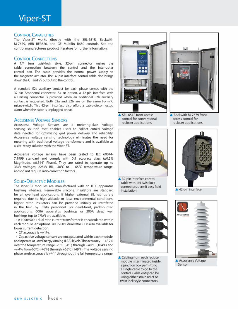
cOntrOL capabiLitiesThe Viper-ST works directly with the SEL-651R, Beckwith M-7679, ABB RER620, and GE Multilin R650 controls. See the control manufacturers product literature for further information.
cOntrOL cOnnectiOnsA 1/4 turn twist-lock style, 32-pin connector makes the cable connection between the control and the interrupter control box. The cable provides the normal power supply to the magnetic actuator. The 32-pin interface control cable also brings down the CT and VS outputs to the control.
A standard 52a auxiliary contact for each phase comes with the 32-pin Amphenol connector. As an option, a 42-pin interface with a Harting connector is provided when an additional 52b auxiliary contact is requested. Both 52a and 52b are on the same Form C micro-switch. This 42-pin interface also offers a cable-disconnected alarm when the cable is unplugged or cut.
accusense VOLtage sensOrsAccusense Voltage Sensors are a metering-class voltage sensing solution that enables users to collect critical voltage data needed for optimizing grid power delivery and reliability. Accusense voltage sensing technology eliminates the need for metering with traditional voltage transformers and is available as a site-ready solution with the Viper-ST.
Accusense voltage sensors have been tested to IEC 60044-7:1999 standard and comply with 0.5 accuracy class (±0.5% Magnitude, ±0.344° Phase). They are rated to operate up to 38kV voltages, 225kV BIL, -40°C to + 65°C temperature range, and do not require ratio correction factors.
sOLiD-DieLectric MODuLesThe Viper-ST modules are manufactured with an IEEE apparatus bushing interface. Removable silicone insulators are standard for all overhead applications. If higher external BIL ratings are required due to high altitude or local environmental conditions, higher rated insulators can be provided initially or retrofitted in the field by utility personnel. For dead-front, padmounted applications, 600A apparatus bushings or 200A deep well bushings (up to 27kV) are available. • A 1000/500:1 dual ratio current transformer is encapsulated within each module. An optional 400/200:1 dual ratio CT is also available for lower current detection. • CT accuracy is +/-1%. • Capacitive voltage sensors are encapsulated within each module and operate at Low Energy Analog (LEA) levels. The accuracy +/-2% over the temperature range -20°C (-4°F) through +40°C (104°F) and +/-4% from-60°C (-76°F) through +65°C (149°F). The voltage sensing phase angle accuracy is +/-1° throughout the full temperature range.
▲ SEL-651R front access control for conventional recloser applications.
▲ 32-pin interface control cable with 1/4 twist lock connectors permit easy field installation.
▲ Cabling from each recloser module is terminated inside a junction box permitting a single cable to go to the control. Cable entry can be using either strain relief or twist lock style connectors.
▲ 42-pin interface.
▲ Accusense Voltage Sensor
▲ Beckwith M-7679 front access control for recloser applications.

G & W E L E C T R I C P A G E 5
Polemount Center Bracket (15kV drawing shown)*Centermount frames are available in aluminum as standard. These frames can be designed to incorporate site-ready accessories, such as potential transformers and lightning arrestors.
Full site-ready Alley-arm with two oil PTs (15kV shown)*Mounting bracket can be mounted on either side of the Viper-ST to match overhead lines. Bracket position can be changed onsite without the need of special tools.
49”(1245mm)
15”(381mm)
15”(381mm)
51”(1286mm)
61”(1541mm)
* Dimensions are approximate. Do not use for construction. Brackets are aluminum as standard.
▲ 38kV center polemount Viper-ST
49"(1245mm)
15"(381mm)
15"(381mm)
49"(1245mm)
39"(925mm)
p Optional 3-phase ganged manual trip handle.

G & W E L E C T R I C P A G E 6
Viper-ST
Polemount Site-Ready Assembly (15kV shown)Preassembly of all auxiliary equipment significantly reduces recloser preparation time for product installation in the field. It includes oil potential transformers or solid-dielectric voltage transformers, arresters, aerial lugs, terminal/junction boxes, wildlife protectors and all associated wiring. Control cables are connectorized on both ends. Various lengths are available for a cleaner installation. User identification markers can be pre-applied to each unit prior to shipment further reducing installation time. Galvanized steel frames are standard and stainless steel frames are an option.
Lightning Arresters
Primary Connections
Oil PTs
Wildlife Protectors
* Dimensions are approximate. Do not use for construction.
Cross-arm frame (15kV shown)*Phase B can be moved at site, without special tools, to either side of the pole to match the overhead line configuration. Shown as a site-ready unit. Galvanized steel frames are standard.
40”(1016mm)
113"(2870mm)
49”(1241mm)
15”(381mm)
54”(1362mm)

G & W E L E C T R I C P A G E 7
Polemount Cluster Bracket (15kV shown)* Horizontal Insulator Bracket (38kV shown)*This configuration is ideal for overhead applications where all three phase conductors are on the same side of the pole or for congested installations with minimal phase spacing. Galvanized bracket is standard.
* Dimensions are approximate. Do not use for construction.
47”(1190mm)
25”(627mm)
25”(627mm)
90"(2277mm)
41”(1030mm)
140"(3560mm)
58"(1462mm)
Viper-ST with Accusense (27kV shown)*Centermount or cross-arm frames with factory installed Accusense voltage sensors and lightning arrestors. Additional site-ready options are available, such as potential transformers for control power. Aluminum frames are standard.
n .75 X 3.00[19] [76]
27.75[705]
MOUNTING
3.88[98]
n .75[19]
n 2.50[64]
41.71[1060]
49.13[1248]
1.89[48]
RECLOSER SPECIFICS: - RECLOSER IS NOT EQUIPPED WITH A CONTROL: THE RECLOSER WILL GO THROUGH FACTORY TESTING USING THE HOUSE CONTROL - CONTROL CABLE IS CONNECTORIZED ON BOTH ENDS. CABLE LENGTH IS 30 FT. - RECLOSER SUPPLIED WITH CLAMP STYLE AERIAL LUGS (CONDUCTOR RANGE = #2 - 500 MCM) - CT RATIO FACTORY SET AT 1000:1 RATIO - 27KV "Z" AND 27KV "Y" INSULATORS - HARDWIRED JUNCTION BOX - VIPER IS EQUIPPED WITH LOW ENERGY ANALOG (LEA) VOLTAGE SENSING ON "Y" SIDE - ACCUSENSE EXTERNAL VOLTAGE SENSORS (EVS) ARE APPLIED TO THE "Z" SIDE AND PROVIDE 0.5 ACCURACY LOW ENERGY ANALOG VOLTAGE SENSING TO THE RECLOSER CONTROL WITH A 5,000:1 RATIO. G&W WILL CONNECT THE PRIMARY SIDE OF THE ACCUSENSE EVS TO THE RESPECTIVE PHASES. - MAXIMUM OUTPUT OF VOLTAGE SENSING IS 5 VAC WITH A 10,000:1 RATIO - VOLTAGE SENSING IS CALIBRATED AT THE FACTORY USING RATIO CORRECTION FACTORS (RCFS) PROVIDED WITH THE VIPER - RCFS ARE PROGRAMMED INTO THE CUSTOMER SUPPLIED CONROL. SEE LABEL INCLUDED WITH VIPER FOR RCF VALUES AND EQUIVALENT PT RATIO. TOP VIEW
GROUNDINGLUG
MOUNTING POLE(SEE NOTE 8)
BACK VIEW
LIGHTNING ARRESTER(SEE NOTE 9)
RATIO CORRECTIONFACTORS STICKER
ON FRONT OFJUNCTION BOX
INTERNALHAZARD WARNING LABEL
TYPICAL ON BACK SURFACEOF COVER
MODULE CABLEACCESS
CONTACT POSITIONINDICATOR
(RED-CLOSED) (GREEN-OPEN)
ACCUSENSE EXTERNALVOLTAGE SENSOR
CONTROLCABLE ACCESS
42"(1067mm)
49"(1248mm)
54"(1372mm)
G & W E L E C T R I C P A G E 8
Viper-ST
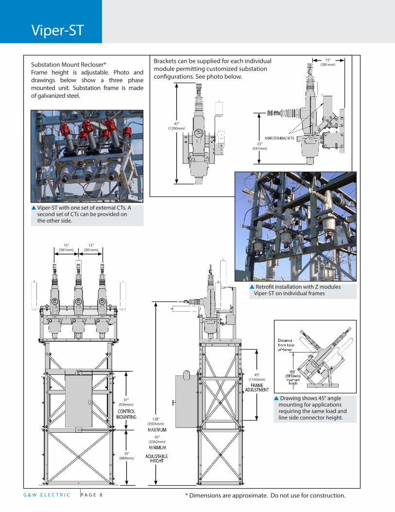
Substation Mount Recloser*Frame height is adjustable. Photo and drawings below show a three phase mounted unit. Substation frame is made of galvanized steel.
Brackets can be supplied for each individual module permitting customized substation configurations. See photo below.
▲ Drawing shows 45° angle mounting for applications requiring the same load and line side connector height.
▲ Viper-ST with one set of external CTs. A second set of CTs can be provided on the other side.
▲ Retrofit installation with Z modules Viper-ST on individual frames
23”(591mm)
15”(381mm)
15”(381mm)
15”(381mm)
37”(939mm)
35”(889mm)
138”(3505mm)
93”(2362mm)
45”(1143mm)
47”(1200mm)
* Dimensions are approximate. Do not use for construction.

G & W E L E C T R I C P A G E 9
paDMOunt appLicatiOnsFor applications where space is limited at the substation or where underground feeders require protection, Viper-ST solid-dielectric reclosers can provide an ideal solution using a dead-front padmount design. The padmounted Viper-ST can be used as a breaker or as a tie-switch. Padmount applications can be considered for fenceless substations. In this configuration, the cable connections can be provided with either a standard IEEE 600A apparatus or 200A deepwell interface for elbow connectors. Controls can be mounted inside the recloser enclosure or within a separate adjacent low voltage enclosure. Up to six internal LEA voltage sensors can be provided on padmounted designs with Z or C modules, perfect for tie points on FDIR schemes and automatic transfer applications.
Padmount Reclosers with Front only or Front / Back Access*Galvanized steel enclosure is standard. Stainless steel is optional.
MODuLe cOnFiguratiOns
“C” Module “Z” Module
52”(1321mm)
51”(1295mm)
* Dimensions are approximate. Do not use for construction.

G & W E L E C T R I C P A G E 1 0
Typical SpecificationsDESIGN RATINGS AND STANDARDSReclosers shall be designed, tested and built per IEEE C37.60 and IEC 62271-111 standards. Certified test reports shall be provided. The recloser shall be rated (select column):
Max System Voltage (kV) 15.5 27 38
Rated Voltage (kV) 15 25 35***
Interrupting Rating RMS (kA) 16* 16* 12.5
BIL (kV) 110 125 150
Continuous Current (A) 800/1000**
800/1000** 800
8 Hr. Overload, at 20° C 960 960 960
Making Current, RMS, asym, KA 25* 25* 20
Peak, asym (kA) 42* 42* 32
Short Circuit Current, kA sym,
3 seconds16* 16* 12.5
60Hz Withstand, kV rms Dry, 1 second 50 60 60
60Hz Withstand, kV rms Wet, 10 seconds 45 50 50
Operating Temperature -60˚C to +65˚C
OptiOns*
The following options shall be supplied: (Check as necessary)___ NEMA 2-hole aerial lugs___ NEMA 4-hole aerial lugs___ Clamp style aerial lugs (#2 - 500 kcmil)___ Clamp style aerial lugs (250 -750 kcmil)___ 4/0 brass eyebolt ground lug___ Galvanized polemount center bracket with arrester provisions on the load and source side ___ Stainless steel polemount center bracket with arrester provisions on the load and source side ___ Stainless steel polemount side bracket with arrester provisions on the load and source side___ Stainless steel substation frame ___ Polemount site-ready assembly ___ Lightning arresters ___ Dead-front padmounted design with stainless steel enclosure ___ External Accusense Voltage Sensors (0.5 class accuracy)___ External 1.0 KVA oil potential transformer (3% accuracy) for 120 VAC supply power with hardware to mount on standard aluminum frame___ External 0.75 KVA solid-dielectric voltage transformer (0.3% accuracy) for 120 VAC supply power with hardware to mount on standard aluminum frame___ High impact, UV stable wildlife protectors for source and load insulators___ External CTs for current monitoring ___ Six internal voltage sensors___ Junction box with all twist lock connections ___ 42 pin interface with additional 52b auxiliary contact (Form C type) and cable-disconnected alarm ___ 3-phase ganged manual trip handle
* Additional Cost
t NEMA 4-hole, 2-hole and clamp style aerial lugs.
Visit gwelec.com/specs.html for electronic versions of typical specifications.
* 29.3kV system voltages are available** Consult factory for higher continuous current up to 1000A# 12.5kA Interrupting Current rating available
Voltage Class Catalog Number
15.5kV VIP378ER-[12 or 16]*-1-ST
27kV VIP388ER-[12 or 16]*-1-ST
38kV VIP398ER-[12 or 16]*-1-ST
*12=12.5kA sym. fault interrupting or 16=16kA sym. fault interrupting
Approximate weight (for single-phase module less frame) is 100lbs. (45kg)

G & W E L E C T R I C P A G E 1 1
Reclosers play a critical role in improving distribution reliability. By applying Viper-ST reclosers on the distribution system, permanent faults can be isolated to minimize outage areas and temporary faults can be cleared to restore power, thereby improving service continuity and system reliability.
The G&W Viper-ST can be used in a variety of applications including stand-alone reclosers, complex loop schemes with sectionalizing and tie switches, replacements for circuit breakers for feeder protection, and distributed generation intertie switches. The Viper-ST recloser is a versatile solution for your over-current protection and distribution automation needs.
High accuracy Accusense voltage sensors integrated with the Viper-ST can be used as a tool to assist in improving power optimization initiatives such as volt-var optimization (VVO), conservation voltage reduction (CVR), and end-of-line metering. The Viper-ST solution with Accusense voltage sensors can serve as a metering point to provide data required for power factor adjustments, reducing voltages, optimizing voltages, and managing peak loads. External CT's can be installed over the Viper insulators for applications requiring high accuracy current measurement.
Stand-Alone Recloser ApplicationTemporary Fault Between Viper and Load
LOAD SOURCE
VIPER RECLOSER
▲ Figure 1: Stand-Alone Viper Recloser trips on a fault
1. A tree branch falls on the line causing a fault between the Viper recloser and Load.2. The Viper recloser begins reclose sequence and trips open, as shown in Figure 1.
LOAD SOURCE
VIPER RECLOSER
Power is restored
▲ Figure 2: Stand Alone Recloser restores power after temporary fault cleared3. A tree branch falls and the temporary fault clears.4. The Viper recloser closes, as shown in Figure 2.
Loop Scheme ApplicationLoop schemes generally consist of two or more sources tied into a distribution system to ensure backup power is available when the primary feeder is lost. The scheme utilizes sectionalizers and tie switches to automatically isolate the fault, quickly and reliably restores power to all areas unaffected by the fault.
Open Loop Viper-ST Application
LOAD 1
LOAD 2
LOAD 3
LOAD 4
SOURCE 1
VIPER RECLOSER 1
VIPER SECTIONALIZER 1
VIPER TIE SWITCH
SOURCE 2
VIPER RECLOSER 2
VIPER SECTIONALIZER 2
▲ Figure 3: Open Loop Scheme Configuration
Permanent Fault Between Recloser 1 and Sectionalizer 11. Viper Recloser 1Trips open, operates through its reclosing sequences and locks-out2. Viper Sectionalizer 1 opens after Viper Recloser 1 trips to lock-out, isolating the fault. The power is lost between Viper Tie Switch and Viper Sectionalizer 13. The Viper Tie Switch closes4. Power is restored to Load 2, as shown in Figure 4. Note: Custom relay programming may be required for Viper loop scheme applications.
LOAD 1
LOAD 2
LOAD 3
LOAD 4
SOURCE 1
VIPER RECLOSER 1
VIPER SECTIONAZLIER 1
VIPER TIE SWITCH
SOURCE 2
VIPER RECLOSER 2
VIPER SECTIONALIZER 2
POWER IS RESTOREDTO LOAD 2
▲ Figure 4: Open Loop Scheme with Fault Isolated
Automatic TransferFor critical load applications such as hospitals, processing plants, and military bases among others, automatic transfer schemes are common. For overhead systems, this scheme requires two switches, voltage sensors & current transformers, and a voltage-time controller. A loss of voltage on the primary source is sensed and initiates the control to open the primary source and close the alternate source switch to automatically restore power.
Lazer AutomationThe distribution automation expertise and products of G&W have been combined to provide a state of the art solution called Lazer Automation. Various levels of Lazer Solutions are available for peer-to-peer product applications, stand-alone controller based systems and total system wide management and control.
Applications

G&W offers a complete line of smart distribution voltage equipment including:
SF6 Insulated Switchgear• To 38kV, 25kA interrupting• Submersible vault and padmount• Smart Grid / Lazer® solutions• Load and Fault Interrupting
Solid-Dielectric Switchgear• To 38kV, 16kA interrupting• Submersible vault and padmount• Smart Grid / Lazer® solutions• Single phase and three phase• Integral Visible Break Designs
Solid-Dielectric Reclosers• To 38kV, 12.5kA interrupting• To 27kV, 16kA interrupting• Overhead, substation and padmount• Smart Grid / Lazer® solutions• Single phase and three phase• Six voltage sensing available
Lazer® Automation
• Multiple levels of protection• Open, flexible communication• Pre-engineered, factory tested• Transfer, loop, and network applications
G&W Electric Company305 W. Crossroads PkwyBolingbrook, IL 60440-4938 USATel 708.388.5010 Fax 708.388.0755
www.gwelec.com Catalog O-vst18April, 2018


