Solid carbide end-mills - miller-tools.de · CONTENTS 01 Introduction Milling competence 6...
146
The tool specialists for the trade.
Transcript of Solid carbide end-mills - miller-tools.de · CONTENTS 01 Introduction Milling competence 6...

Solid carbide end-millsStandard programme
The tool specialists for the trade.
MIL
LER
stan
dard
pro
gram
me
– so
lid c
arbi
de e
nd-m
ills

Miller GmbH & Co. KG, Präzisionswerkzeuge in Altenstadt produces solid carbide precision tools for drilling and milling with resounding success and an innovative production strategy. PCD tools for drilling into the solid round off the product portfolio.
The greatest strengths of MILLER are its extensive range of standard products with application-specific catalogue tools as well as its high degree of flexibility in develo-ping outstanding complex special tools made of solid carbide.
INNOVATIVE PRODUCTION STRATEGIES FOR YOURTECHNICAL ADVANCE
tool-tra
Miller GmbH & Co. KG, Präzisionswerkzeuge in Altenstadt is a member of the "tool-traders-partner" association and takes the advantages of this strong community to the benefit of its customers and the quality of its products.For further information see the last pages of this catalogue or visit us on the internet at www.tool-traders-partner.com.

ders-partner.com

4

CONTENTS01 Introduction
Milling competence 6
Programme overview 8
Innovations | Highlights 10
02 End-mills
with fixed cutting edges
Product overview, selection aid, model key 14
Shoulder milling cutters
Groove milling and general applications 26
Shoulder milling – roughing 76
Shoulder milling – finishing 82
Trochoidal milling 90
Profile milling cutters 98
Chamfering, drill and deburring milling cutters 104
Custom solutions 108
03 Technical appendix
General technical information 114
Cutting data recommendation 118
5

MILLING | Introduction
MILLING COMPETENCE
In the area of milling, MILLER tool experts have developednumerous machining solutions in recent years. The focushas been on tools adapted to the related customerrequirements. Along with these individual tool solutions,however, the usage of high-performance standardtools plays a major role in many applications. Thereforea comprehensive standard programme has evolved fromthese custom tools.
MILLER's many years of experience, accumulated know-how and high level of processunderstanding in the area of milling are reflected in the standard programme. Process reliability,efficiency and the highest productivity for customers are therefore guaranteed.
Milling cutters from MILLER arrive at the customer after extensive research and developmentwork, design and simulation using the latest software, production and finally inspection on thelatest manufacturing equipment. In conjunction with the most efficient cutting materials, MILLERtherefore offers the optimal milling tool for almost all applications and workpiece materials.
For all applicationsMILLER offers a suitable tool for every millingtask. All types of machining – whether general machining operation such as groove milling, face milling, shoulder milling, for roughing and finishing, or special machining operations such as trochoidal or helix milling – are covered with innovative tool solutions.
For every materialAlong with the type of machining operation, the workpiece material is the most important crite-rion for selecting a suitable milling cutter. Along with tools for machining steel, cast iron and aluminium, the programme from MILLER also includes solutions for the cost-effective, reliab-le milling of titanium, super alloys, plastics and composite materials.
Custom solutionsSpecial machining tasks require special tools. For this reason MILLER offers custom milling tools individually tailored to the requirements of the customer. For instance, complex shapes and contours can be realised using specifically designed milling cutters, or machining times and tools changes reduced using combination tools.
6

MILLING | Introduction
High-performance coatingsA crucial criterion for the service life of the tool and optimal machining results is the coating of the cutting edges. MILLER offers a large selec-tion of substrates and coatings, each matched to the specific machining case.
Latest manufacturing equipmentThe latest 3D design and simulations form the basis for the manufacture of MILLER tools. The data are transferred via interfaces to the related machining centre that forms part of the modern, comprehensive range of machinery available on-site. In this way the production of MILLER milling tools for the highest quality requirements is moni-tored and controlled by experienced staff.
Reconditioning in original qualityBy reconditioning solid carbide tools with original grinding and original coating, almost 100 percent of the tool life of new tools can be achieved again. Upon request, MILLER will collect and deliver the tools for quick processing.
7

1.3
1.1
23
5
N C
P M K N S H
P M K N
MILLING | Introduction
N
END-MILLS WITH FIXED CUTTING EDGES
PROGRAMME OVERVIEWAt a glance
1 Groove milling and general applications
1.2 High volume machining of structural parts
1.3 Milling modern lightweight materials
Diameter range: 1-32 mm
Diameter range: 6-32 mm
Diameter range: 1-20 mmu more from page 27
3 Shoulder milling – finishing
P M K N H
Diameter range: 4-32 mmu more from page 83
2 Shoulder milling – roughing
Diameter range: 4-25 mmu more from page 77
1.1 OptiMill standard programme
8

6
1.2
4
1.1
P M K NP M CK N H
MILLING | Introduction
6 Chamfering, deburring, drill milling
Diameter range: 3-20 mmu more from page 105
5 Profile milling
Diameter range: 1-25 mmu more from page 99
4 Trochoidal milling
KP M S H
Diameter range: 5-25 mmu more from page 91
Feed direction
9

MILLING | Introduction
The OptiMill-Uni-HPC-Plus is the logical further development of the OptiMill-Uni-HPC. A high-per-formance substrate in combination with a newly developed coating guarantees excellent tool lives. The precise rounding of the cutting edges en-sures low wear with good surface quality at the same time. Very smooth running, large cutting volumes, high process reliability and low machi-ne load are achieved during the machining ope-ration by means of the use of varying pitch and
unequal tooth spacing. The OptiMill-Uni-HPC-Plus is designed for the highly cost-effective universal machining of steel, stainless steel and cast iron. It is available in the diameter range from 3 to 25 mm in the designs short, long, overlong and extra long.
AT A GLANCE
- High-performance substrate and high-end
coating for excellent tool lives
- Dynamic helix pitch and unequal spacing
for particularly smooth running
- Precise cutting edge for a high surface quality
OptiMill®-Uni-HPC-PlusA new dimension for universal machining in relation toquality, precision and durability
u more on pages 42-45
The high-performance roughing milling cutter OptiMill-Uni-HPC-Rough is a highlight in the series of MILLER HPC milling cutters. The new knurled profile guarantees an optimal distribution of cutting forces and in this way ensures better chip formation. Due to the unequal spacing of the cutting edges, significantly less oscillation and vibration are produced. As a consequence high-er cutting speeds and feed rates are possible. In conjunction with a newly developed coating, the
highest material removal rates are achieved with increased tool life at the same. The range inclu-des milling cutters in the diameter range from 4 to 25 mm and is available in short and long designs.
AT A GLANCE
- Unequal spacing for low vibration running
- High-performance coating for maximum
tool lives
- New knurled profile for optimised force
distribution on the cutting edges and
therefore better chip formation
OptiMill®-Uni-HPC-RoughThe guarantor for highly cost-effective roughing
u more on pages 79/80
INNOVATIONS | HIGHLIGHTS End-mills with fixed cutting edges
10

MILLING | Introduction
For trochoidal milling, MILLER has expanded its OptiMill solid carbide range with milling cutters that have a cutting length of 3xD. Especially de-veloped for trochoidal machining, these milling cutters have five cutting edges with optimised unequal spacing and geometry. These features combined with the balancing of the cutting tool to G2.5 ensure reduced vibration and high surface finishes. Workpiece-specific chip breakers ensu-re the trouble-free removal of chips. The range
includes milling cutters in the diameter range from 5 to 25 mm for machining steel, cast steel, inox, titanium, high-alloy steels as well as hard machining.
MILLER has developed a new range of aluminiumroughing end-mills. The OptiMill-Volume-N high-performance end-mills are characterised by a high level of rigidity thanks to rounded transitions on the tool shank for preventing notch effects as well as large flute angles and axial angles. Large chip flutes with rounded surfaces result in re-liable chip removal, thereby ensuring process reliability. Regenerative chatter vibrations when machining aluminium is counteracted by tool
flank chamfers and uneven cutting edge pitches on the tools.
AT A GLANCE
- Cutting depths of 3xD with special
chip breaker geometry
- Maximum material removal rate
- Shorter machining times
- Low machining forces
- Highest tool lives
- Optimal chip transport
OptiMill®-TrochoidMaximum machining efficiency during trochoidal milling
u more from page 90
OptiMill®-Volume-NNew generation of high-volume milling cutters for machining aluminium
u more on Page 55
AT A GLANCE
- Diameter range from 6,00 to 32,00 mm
- Short (M3593) and long (M3591) design
available from stock
- Three cutting edges with highly polished flutes
ADVANTAGES
- High material removal rate
- Soft, low-vibration cutting thanks to highly
positive rake angle and increased axis angle:
Higher quality, lower power consumption
- Optimised chip flow:
No corners or sharp edges along the chip flute
- High level of rigidity
11

MILLING | End-mills with fixed cutting edges
Optimal milling cutters for almost all applications and workpiece materials
MILLING CUTTERS WITH FIXED CUTTING EDGES
12

MILLING | End-mills with fixed cutting edges 13

MILLING | End-mills with fixed cutting edges
The high-performance end-mill program-me OptiMill from MILLER ensures excellent, reliable results during all machining tasks. The focus is on cost-effectiveness and product quality, along with meeting customer require-ments.
Application-orientatedThe end-mill programme from MILLER includes shoulder milling cutters for groove milling, roughing, finishing and trochoidal milling, as well as milling cutters for high feed milling, profile milling and chamfering.
Always the right choiceIrrespective of whether you need a cost-effectivemilling cutter for universal machining or an expert for a complex machining task – MILLER offers the right tool.
PRODUCT OVERVIEWEnd-mills with fixed cutting edges
Expert Line: Specialist tools for selectedapplications, maximum precisionand productivity
Performance Line: High-performance tools, broad application area, high productivity in series production manufacturing
Basic Line: Universal tools, broad applicationarea, low procurement costs
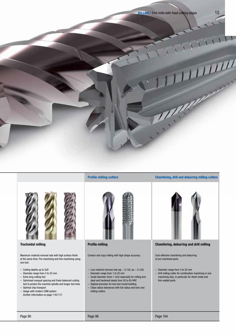
Shoulder milling cutters Profile milling cutters Chamfering, drill and deburring milling cutters
Groove milling and general applications
Milling cutters for general applications.Excellently suited to groove milling.
– Contact width ae up to 1xD– Diameter range from 1 to 25 mm– Optimal chip transport– Large selection of lengths and geometries for all
applications– High-performance substrate and modern coatings
for excellent tool lives
Shoulder milling – roughing
To achieve the highest material removal.Ideal for pre-machining with high stock removal.
– High material removal rate (ae ~ 0.6xD)– Diameter range from 4 to 25 mm– New knurled profile for optimal force distribution on the
cutting edge– Profile undercut roughing teeth– Unequal spacing for low vibration running
Shoulder milling – finishing
Ideal for producing the best surface finishes. Fine machining with low stock removal.
– Low material removal rate (ae ≤ 0.1xD)– Diameter range from 4 to 32 mm– Large number of teeth– Optimal distribution of the cutting forces– Special design for hardened steels of 50-65 HRC
Trochoidal milling
Maximum material removal rate with high surface finish at the same time. Pre-machining and fine machining using one tool.
– Cutting depths up to 3xD– Diameter range from 4 to 25 mm– Extra long cutting tool– Optimised unequal spacing and finely balanced cutting
tool to protect the machine spindle and longer tool lives– Optimal chip transport– Usage with modern CAM system (further information on page 116/117)
Profile milling
Contour and copy milling with high shape accuracy.
– Low material removal rate (ap ~ 0.1xD, ae ~ 0.1xD)– Diameter range from 1 to 25 mm– Small diameter (from 1 mm) especially for milling tool
steel and hardened steels from 50 to 65 HRC– Highest precision for tool and mould building– Close radius tolerances with full radius and toric end
milling cutters
Chamfering, deburring and drill milling
Cost-effective chamfering and deburringof pre-machined parts.
– Diameter range from 3 to 20 mm– Drill milling cutter for combination machining in one
machining step, in particular for sheet metal and thin-walled parts
Page 26 Page 76 Page 82 Page 90 Page 98 Page 104
14
MILLING | End-mills with fixed cutting edges
Shoulder milling cutters Profile milling cutters Chamfering, drill and deburring milling cutters
Groove milling and general applications
Milling cutters for general applications.Excellently suited to groove milling.
– Contact width ae up to 1xD– Diameter range from 1 to 25 mm– Optimal chip transport– Large selection of lengths and geometries for all
applications– High-performance substrate and modern coatings
for excellent tool lives
Shoulder milling – roughing
To achieve the highest material removal.Ideal for pre-machining with high stock removal.
– High material removal rate (ae ~ 0.6xD)– Diameter range from 4 to 25 mm– New knurled profile for optimal force distribution on the
cutting edge– Profile undercut roughing teeth– Unequal spacing for low vibration running
Shoulder milling – finishing
Ideal for producing the best surface finishes. Fine machining with low stock removal.
– Low material removal rate (ae ≤ 0.1xD)– Diameter range from 4 to 32 mm– Large number of teeth– Optimal distribution of the cutting forces– Special design for hardened steels of 50-65 HRC
Trochoidal milling
Maximum material removal rate with high surface finish at the same time. Pre-machining and fine machining using one tool.
– Cutting depths up to 3xD– Diameter range from 4 to 25 mm– Extra long cutting tool– Optimised unequal spacing and finely balanced cutting
tool to protect the machine spindle and longer tool lives– Optimal chip transport– Usage with modern CAM system (further information on page 116/117)
Profile milling
Contour and copy milling with high shape accuracy.
– Low material removal rate (ap ~ 0.1xD, ae ~ 0.1xD)– Diameter range from 1 to 25 mm– Small diameter (from 1 mm) especially for milling tool
steel and hardened steels from 50 to 65 HRC– Highest precision for tool and mould building– Close radius tolerances with full radius and toric end
milling cutters
Chamfering, deburring and drill milling
Cost-effective chamfering and deburringof pre-machined parts.
– Diameter range from 3 to 20 mm– Drill milling cutter for combination machining in one
machining step, in particular for sheet metal and thin-walled parts
Page 26 Page 76 Page 82 Page 90 Page 98 Page 104
15

1
P M
2
3
4
5.1
5.2
6
MILLING | End-mills with fixed cutting edges
Step-by-step to the right milling cutter
SELECTION OF A MILLING CUTTER
You are looking for an end-mill especially for trochoidal milling difficult-to-machine materials such as titanium and nickel-based alloys?This selection aid will lead you step-by-step to the right milling cutter.
Select your main application.
Select your preferred design.
Decide for a product class.
Identify your workpiece material as per the MMG(MILLER machining group).
Select the required cutting edge design.
Check whether the geometric features meet your requirements.
Select your milling cutter. If there are several possibleselections, select the milling cutter that is markedas 1st choice for material suitability.
Application
Design
Product class
Material suitability
Cutting edgedesign
Other geometryfeatures
Product
Groove milling and generalapplications
Monolithic
Basic Line: Universal tools, broad application area,low procurement costs
Steel
45° chamfer
Diameter range
Shoulder milling –roughing
Stainlesssteel
Sharp edged
Number of teeth
16

K N S HC
MILLING | End-mills with fixed cutting edges
Performance Line: High-performance tools, broad application area,high productivity in series production manufacturing
Shoulder milling –finishing
Expert Line:Specialist tools for selected applications,maximum precision and productivity
Cast iron
Corner radius
Axis/helix angle
Trochoidalmilling
Non-ferrousmetals andplastics
Full radius
Cutting material
Compositematerials
Drill tip
Cooling supply
Profile milling
Super alloysand titanium
Chamferingand deburring
Hardened steeland cast steel
17

MILLING | End-mills with fixed cutting edges
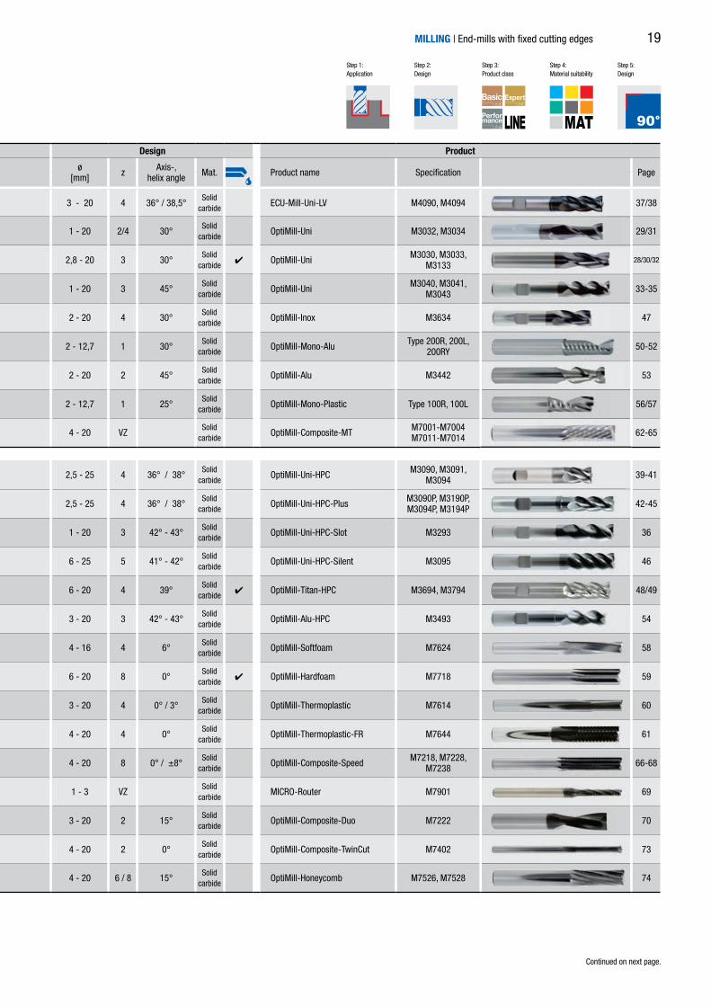
4 3 - 20 4 36° / 38,5°Solid
carbideECU-Mill-Uni-LV M4090, M4094 37/38
4 4 1 - 20 2/4 30°Solid
carbideOptiMill-Uni M3032, M3034 29/31
4 2,8 - 20 3 30°Solid
carbide 4 OptiMill-Uni M3030, M3033, M3133
28/30/32
4 4 1 - 20 3 45°Solid
carbideOptiMill-Uni M3040, M3041,
M3043 33-35
4 2 - 20 4 30°Solid
carbideOptiMill-Inox M3634 47
4 4 2 - 12,7 1 30°Solid
carbideOptiMill-Mono-Alu Type 200R, 200L,
200RY 50-52
4 2 - 20 2 45°Solid
carbideOptiMill-Alu M3442 53
4 2 - 12,7 1 25°Solid
carbideOptiMill-Mono-Plastic Type 100R, 100L 56/57
4 4 4 - 20 VZSolid
carbideOptiMill-Composite-MT M7001-M7004
M7011-M7014 62-65
4 4 2,5 - 25 4 36° / 38°Solid
carbideOptiMill-Uni-HPC M3090, M3091,
M3094 39-41
4 4 2,5 - 25 4 36° / 38°Solid
carbideOptiMill-Uni-HPC-Plus M3090P, M3190P,
M3094P, M3194P 42-45
4 4 1 - 20 3 42° - 43°Solid
carbideOptiMill-Uni-HPC-Slot M3293 36
4 6 - 25 5 41° - 42°Solid
carbideOptiMill-Uni-HPC-Silent M3095 46
4 4 6 - 20 4 39°Solid
carbide 4 OptiMill-Titan-HPC M3694, M3794 48/49
4 3 - 20 3 42° - 43°Solid
carbideOptiMill-Alu-HPC M3493 54
4 4 - 16 4 6°Solid
carbideOptiMill-Softfoam M7624 58
4 6 - 20 8 0°Solid
carbide 4 OptiMill-Hardfoam M7718 59
4 3 - 20 4 0° / 3°Solid
carbideOptiMill-Thermoplastic M7614 60
4 4 - 20 4 0°Solid
carbideOptiMill-Thermoplastic-FR M7644 61
4 4 - 20 8 0° / ±8°Solid
carbideOptiMill-Composite-Speed M7218, M7228,
M7238 66-68
4 1 - 3 VZSolid
carbideMICRO-Router M7901 69
4 3 - 20 2 15°Solid
carbideOptiMill-Composite-Duo M7222 70
4 4 - 20 2 0°Solid
carbideOptiMill-Composite-TwinCut M7402 73
4 4 - 20 6 / 8 15°Solid
carbideOptiMill-Honeycomb M7526, M7528 74
highly suitable suitable in some situations 1st choice
Shoulder milling cutters | Groove milling and general applications
Design Quality Material suitability Edge design Design ProductP M K N C S H ø
[mm] z Axis-, helix angle Mat. Product name Specification Page
1-6 1-3 1-2 3 1.1 1.2-2.3 3.1 4.1 4.2 4.3 1.1 1.2 1.3 2.1 3.1 4.1 4.2 4.3 4.4 1-2 3-5 1-2
18
MAT
MILLING | End-mills with fixed cutting edges
4 3 - 20 4 36° / 38,5°Solid
carbideECU-Mill-Uni-LV M4090, M4094 37/38
4 4 1 - 20 2/4 30°Solid
carbideOptiMill-Uni M3032, M3034 29/31
4 2,8 - 20 3 30°Solid
carbide 4 OptiMill-Uni M3030, M3033, M3133
28/30/32
4 4 1 - 20 3 45°Solid
carbideOptiMill-Uni M3040, M3041,
M3043 33-35
4 2 - 20 4 30°Solid
carbideOptiMill-Inox M3634 47
4 4 2 - 12,7 1 30°Solid
carbideOptiMill-Mono-Alu Type 200R, 200L,
200RY 50-52
4 2 - 20 2 45°Solid
carbideOptiMill-Alu M3442 53
4 2 - 12,7 1 25°Solid
carbideOptiMill-Mono-Plastic Type 100R, 100L 56/57
4 4 4 - 20 VZSolid
carbideOptiMill-Composite-MT M7001-M7004
M7011-M7014 62-65
4 4 2,5 - 25 4 36° / 38°Solid
carbideOptiMill-Uni-HPC M3090, M3091,
M3094 39-41
4 4 2,5 - 25 4 36° / 38°Solid
carbideOptiMill-Uni-HPC-Plus M3090P, M3190P,
M3094P, M3194P 42-45
4 4 1 - 20 3 42° - 43°Solid
carbideOptiMill-Uni-HPC-Slot M3293 36
4 6 - 25 5 41° - 42°Solid
carbideOptiMill-Uni-HPC-Silent M3095 46
4 4 6 - 20 4 39°Solid
carbide 4 OptiMill-Titan-HPC M3694, M3794 48/49
4 3 - 20 3 42° - 43°Solid
carbideOptiMill-Alu-HPC M3493 54
4 4 - 16 4 6°Solid
carbideOptiMill-Softfoam M7624 58
4 6 - 20 8 0°Solid
carbide 4 OptiMill-Hardfoam M7718 59
4 3 - 20 4 0° / 3°Solid
carbideOptiMill-Thermoplastic M7614 60
4 4 - 20 4 0°Solid
carbideOptiMill-Thermoplastic-FR M7644 61
4 4 - 20 8 0° / ±8°Solid
carbideOptiMill-Composite-Speed M7218, M7228,
M7238 66-68
4 1 - 3 VZSolid
carbideMICRO-Router M7901 69
4 3 - 20 2 15°Solid
carbideOptiMill-Composite-Duo M7222 70
4 4 - 20 2 0°Solid
carbideOptiMill-Composite-TwinCut M7402 73
4 4 - 20 6 / 8 15°Solid
carbideOptiMill-Honeycomb M7526, M7528 74
Continued on next page.
Step 1: Application
Step 2: Design
Step 3: Product class
Step 4: Material suitability
Step 5: Design
Design Quality Material suitability Edge design Design ProductP M K N C S H ø
[mm] z Axis-, helix angle Mat. Product name Specification Page
1-6 1-3 1-2 3 1.1 1.2-2.3 3.1 4.1 4.2 4.3 1.1 1.2 1.3 2.1 3.1 4.1 4.2 4.3 4.4 1-2 3-5 1-2
19

MILLING | End-mills with fixed cutting edges
bestens geeignet bedingt geeignet 1. Wahl
4 6 - 32 3 43°Solid
carbide 4 OptiMill-Volume-N M3591, M3593 55
4 4 - 20 2 15°Solid
carbideOptiMill-Composite-UD M7212, M7242 71/72
4 4 6 - 20 3 / 4 30°Solid
carbideOptiMill-Uni-Rough & Finish M3060 78
4 4 - 25 3 - 5 30°Solid
carbideOptiMill-Uni-HPC-Rough M3081, M3181 79/80
Shoulder milling cutters | Shoulder milling – roughing
Shoulder milling cutters | Shoulder milling – finishing
4 4 - 32 6 / 8 45°Solid
carbideOptiMill-Uni-Finish M3046, M3048,
M3049 84/85
4 4 - 20 6 / 8 50°Solid
carbideOptiMill-Hardened M3076, M3078,
M3071 87/88
4 6 - 20 6 39° / 41°Solid
carbideOptiMill-Uni-HPC-Finish M3096 86
4 4 - 25 5 41° - 42°Solid
carbideOptiMill-Tro-Uni M3099 92
4 4 - 25 5 41° - 42°Solid
carbideOptiMill-Tro-PM M3299 93
4 5 - 25 5 41° - 42°Solid
carbideOptiMill-Tro-S M3699 94
4 5 - 25 5 41° - 42°Solid
carbideOptiMill-Tro-Titan M3799 95
4 5 - 25 5 41° - 42°Solid
carbideOptiMill-Tro-H M3079 96
Shoulder milling cutters | Trochoidal milling
highly suitable suitable in some situations 1st choice
Shoulder milling cutters | Groove milling and general applications
Design Quality Material suitability Edge design Design ProductP M K N C S H ø
[mm] z Axis-, helix angle Mat. Product name Specification Page
1-6 1-3 1-2 3 1.1 1.2-2.3 3.1 4.1 4.2 4.3 1.1 1.2 1.3 2.1 3.1 4.1 4.2 4.3 4.4 1-2 3-5 1-2
Design Quality Material suitability Edge design Design ProductP M K N C S H ø
[mm] z Axis-, helix angle Mat. Product name Specification Page
1-6 1-3 1-2 3 1.1 1.2-2.3 3.1 4.1 4.2 4.3 1.1 1.2 1.3 2.1 3.1 4.1 4.2 4.3 4.4 1-2 3-5 1-2
Design Quality Material suitability Edge design Design ProductP M K N C S H ø
[mm] z Axis-, helix angle Mat. Product name Specification Page
1-6 1-3 1-2 3 1.1 1.2-2.3 3.1 4.1 4.2 4.3 1.1 1.2 1.3 2.1 3.1 4.1 4.2 4.3 4.4 1-2 3-5 1-2
Design Quality Material suitability Edge design Design ProductP M K N C S H ø
[mm] z Axis-, helix angle Mat. Product name Specification Page
1-6 1-3 1-2 3 1.1 1.2-2.3 3.1 4.1 4.2 4.3 1.1 1.2 1.3 2.1 3.1 4.1 4.2 4.3 4.4 1-2 3-5 1-2
20

MAT
Continued on next page.
MILLING | End-mills with fixed cutting edges
4 6 - 32 3 43°Solid
carbide 4 OptiMill-Volume-N M3591, M3593 55
4 4 - 20 2 15°Solid
carbideOptiMill-Composite-UD M7212, M7242 71/72
4 4 6 - 20 3 / 4 30°Solid
carbideOptiMill-Uni-Rough & Finish M3060 78
4 4 - 25 3 - 5 30°Solid
carbideOptiMill-Uni-HPC-Rough M3081, M3181 79/80
4 4 - 32 6 / 8 45°Solid
carbideOptiMill-Uni-Finish M3046, M3048,
M3049 84/85
4 4 - 20 6 / 8 50°Solid
carbideOptiMill-Hardened M3076, M3078,
M3071 87/88
4 6 - 20 6 39° / 41°Solid
carbideOptiMill-Uni-HPC-Finish M3096 86
4 4 - 25 5 41° - 42°Solid
carbideOptiMill-Tro-Uni M3099 92
4 4 - 25 5 41° - 42°Solid
carbideOptiMill-Tro-PM M3299 93
4 5 - 25 5 41° - 42°Solid
carbideOptiMill-Tro-S M3699 94
4 5 - 25 5 41° - 42°Solid
carbideOptiMill-Tro-Titan M3799 95
4 5 - 25 5 41° - 42°Solid
carbideOptiMill-Tro-H M3079 96
Design Quality Material suitability Edge design Design ProductP M K N C S H ø
[mm] z Axis-, helix angle Mat. Product name Specification Page
1-6 1-3 1-2 3 1.1 1.2-2.3 3.1 4.1 4.2 4.3 1.1 1.2 1.3 2.1 3.1 4.1 4.2 4.3 4.4 1-2 3-5 1-2
Design Quality Material suitability Edge design Design ProductP M K N C S H ø
[mm] z Axis-, helix angle Mat. Product name Specification Page
1-6 1-3 1-2 3 1.1 1.2-2.3 3.1 4.1 4.2 4.3 1.1 1.2 1.3 2.1 3.1 4.1 4.2 4.3 4.4 1-2 3-5 1-2
Design Quality Material suitability Edge design Design ProductP M K N C S H ø
[mm] z Axis-, helix angle Mat. Product name Specification Page
1-6 1-3 1-2 3 1.1 1.2-2.3 3.1 4.1 4.2 4.3 1.1 1.2 1.3 2.1 3.1 4.1 4.2 4.3 4.4 1-2 3-5 1-2
Design Quality Material suitability Edge design Design ProductP M K N C S H ø
[mm] z Axis-, helix angle Mat. Product name Specification Page
1-6 1-3 1-2 3 1.1 1.2-2.3 3.1 4.1 4.2 4.3 1.1 1.2 1.3 2.1 3.1 4.1 4.2 4.3 4.4 1-2 3-5 1-2
Continued on next page.
Step 1: Application
Step 2: Design
Step 3: Product class
Step 4: Material suitability
Step 5: Design
21

MILLING | End-mills with fixed cutting edges
4 2 - 20 2 30°Solid
carbideOptiMill-Uni-Radius M3832 100
4 1 - 20 2 30°Solid
carbideOptiMill-Hardened-Radius M3872 101
4 4 - 20 VZ 25°Solid
carbideOptiMill-Composite-MT-Radius M7801 102
4 4 - 20 4 0°Solid
carbideOptiMill-Chamfer M5390 106
4 3 - 16 2 30°Solid
carbideOptiMill-DrillMill M5490 107
highly suitable suitable in some situations 1st choice
Profile milling
Design Quality Material suitability Edge design Design ProductP M K N C S H ø
[mm] z Axis-, helix angle Mat. Product name Specification Page
1-6 1-3 1-2 3 1.1 1.2-2.3 3.1 4.1 4.2 4.3 1.1 1.2 1.3 2.1 3.1 4.1 4.2 4.3 4.4 1-2 3-5 1-2
Design Quality Material suitability Edge design Design ProductP M K N C S H ø
[mm] z Axis-, helix angle Mat. Product name Specification Page
1-6 1-3 1-2 3 1.1 1.2-2.3 3.1 4.1 4.2 4.3 1.1 1.2 1.3 2.1 3.1 4.1 4.2 4.3 4.4 1-2 3-5 1-2
Chamfering, deburring and drill milling
22

MAT
MILLING | End-mills with fixed cutting edges
4 2 - 20 2 30°Solid
carbideOptiMill-Uni-Radius M3832 100
4 1 - 20 2 30°Solid
carbideOptiMill-Hardened-Radius M3872 101
4 4 - 20 VZ 25°Solid
carbideOptiMill-Composite-MT-Radius M7801 102
4 4 - 20 4 0°Solid
carbideOptiMill-Chamfer M5390 106
4 3 - 16 2 30°Solid
carbideOptiMill-DrillMill M5490 107
Design Quality Material suitability Edge design Design ProductP M K N C S H ø
[mm] z Axis-, helix angle Mat. Product name Specification Page
1-6 1-3 1-2 3 1.1 1.2-2.3 3.1 4.1 4.2 4.3 1.1 1.2 1.3 2.1 3.1 4.1 4.2 4.3 4.4 1-2 3-5 1-2
Design Quality Material suitability Edge design Design ProductP M K N C S H ø
[mm] z Axis-, helix angle Mat. Product name Specification Page
1-6 1-3 1-2 3 1.1 1.2-2.3 3.1 4.1 4.2 4.3 1.1 1.2 1.3 2.1 3.1 4.1 4.2 4.3 4.4 1-2 3-5 1-2
Continued on next page.
Step 1: Application
Step 2: Design
Step 3: Product class
Step 4: Material suitability
Step 5: Design
23

M 3 0 3 2 0 3 0 0 A Z C 0 0 1 0
End-mills with fixed cutting edges
Model key
MILLING | End-mills with fixed cutting edges
End-mill diameterin 0,01 mm
Tool type "End-mill"
24
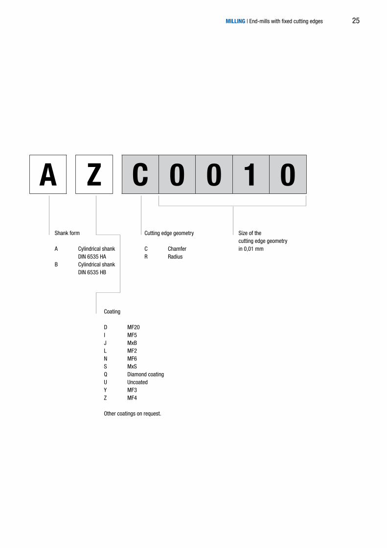
M 3 0 3 2 0 3 0 0 A Z C 0 0 1 0
MILLING | End-mills with fixed cutting edges
Shank form
A Cylindrical shank DIN 6535 HAB Cylindrical shank DIN 6535 HB
Coating
D MF20I MF5J MxBL MF2N MF6S MxSQ Diamond coatingU UncoatedY MF3Z MF4
Other coatings on request.
Size of the cutting edge geometryin 0,01 mm
Cutting edge geometry
C ChamferR Radius
25

MILLING | End-mills with fixed cutting edges26

MILLING | End-mills with fixed cutting edges
Universal use OptiMill-Uni 28
OptiMill-Uni-HPC-Slot 36
ECU-Mill-Uni-LV 37
OptiMill-Uni-HPC 39
OptiMill-Uni-HPC-Plus 42
OptiMill-Uni-HPC-Silent 46
Inox, titanium and super alloys OptiMill-Inox 47
OptiMill-Titan-HPC 48
Non-ferrous metals OptiMill-Mono-Alu 50
OptiMill-Alu 53
OptiMill-Alu-HPC 54
OptiMill-Volume-N 55
Plastics and fibre composite materials OptiMill-Mono-Plastic 56
OptiMill-Softfoam 58
OptiMill-Hardfoam 59
OptiMill-Thermoplastic 60
OptiMill-Thermoplastic-FR 61
OptiMill-Composite-MT 62
OptiMill-Composite-Speed 66
MICRO-Router 69
OptiMill-Composite-Duo 70
OptiMill-Composite-UD 71
OptiMill-Composite-TwinCut 73
OptiMill-Honeycomb 74
GROOVE MILLING AND GENERAL APPLICATIONS
27

P 1 2 3 4 5 6 M 1 2 3 K 1 2 3 N 1 2 3 4 S 1 2 3 4 5 H 1 2
2,00 6 40 4 3 M3030-0200AZ 30247244
2,50 6 40 4 3 M3030-0250AZ 30247245
3,00 6 40 5 3 M3030-0300AZ 30247246
3,50 6 40 5 3 M3030-0350AZ 30247247
4,00 6 40 7 3 M3030-0400AZ 30247248
4,50 6 40 7 3 M3030-0450AZ 30247249
5,00 6 40 8 3 M3030-0500AZ 30247250
5,50 6 40 8 3 M3030-0550AZ 30247251
*5,75 6 40 8 3 M3030-0575AZ 30247252
6,00 6 40 8 3 M3030-0600AZ 30247253
*6,75 8 43 11 3 M3030-0675AZ 30247254
7,00 8 43 11 3 M3030-0700AZ 30247255
*7,75 8 43 11 3 M3030-0775AZ 30247256
8,00 8 43 11 3 M3030-0800AZ 30247257
8,70 10 50 13 3 M3030-0870AZ 30247258
9,00 10 50 13 3 M3030-0900AZ 30247259
*9,70 10 50 13 3 M3030-0970AZ 30247260
10,00 10 50 13 3 M3030-1000AZ 30247261
12,00 12 55 15 3 M3030-1200AZ 30247262
14,00 14 58 15 3 M3030-1400AZ 30247263
16,00 16 62 18 3 M3030-1600AZ 30247264
18,00 18 70 20 3 M3030-1800AZ 30247265
20,00 20 75 22 3 M3030-2000AZ 30247266
HA
DIN 6535
MILLERNORM
d 2 h
6
l1
l2
d 1 h
10
OptiMill®-UniShort design, 30° helix angleM3030
Design:Milling cutter diameter: 2,00-20,00 mmCoating: MF4Number of cutting edges: z = 3Helix angle: 30°
Dimensions z Specification Order No.
d1 h10 d2 h6 l1 l2
Dimensions in mm. *Undersizes especially for keyway milling.Cutting data recommendation from page 118.Special designs and other coatings on request.
MILLING | End-mills with fixed cutting edges28

P 1 2 3 4 5 6 M 1 2 3 K 1 2 3 N 1 2 3 4 S 1 2 3 4 5 H 1 2
d 2 h
6
l2
l1
d 1 h
10
Cx45°
1,00 3 50 3 – 2 M3032-0100AZ 30247129
1,50 3 50 4 – 2 M3032-0150AZ 30247130
2,00 3 50 5 – 2 M3032-0200AZ 30247131
2,50 3 50 6 – 2 M3032-0250AZ 30247132
3,00 6 57 8 0,03 2 M3032-0300BZ 30247133
4,00 6 57 11 0,04 2 M3032-0400BZ 30247134
5,00 6 57 13 0,05 2 M3032-0500BZ 30247135
6,00 6 57 13 0,06 2 M3032-0600BZ 30247136
8,00 8 63 19 0,08 2 M3032-0800BZ 30247137
10,00 10 72 22 0,10 2 M3032-1000BZ 30247138
12,00 12 83 26 0,12 2 M3032-1200BZ 30247139
16,00 16 92 32 0,16 2 M3032-1600BZ 30247140
20,00 20 104 38 0,20 2 M3032-2000BZ 30247141
HA
DIN 6535
HB
DIN 6535 DIN6527
OptiMill®-UniLong design, 30° helix angleM3032
Design:Milling cutter diameter: 1,00-20,00 mmCoating: MF4Number of cutting edges: z = 2Helix angle: 30°
Dimensions z Specification Order No.
d1 h10 d2 h6 l1 l2 C x 45°
Dimensions in mm. Cutting data recommendation from page 118.Special designs and other coatings on request.
MILLING | End-mills with fixed cutting edges 29

d 2 h
6
l2
l1
d 1 h
10
*2,80 6 57 8 3 M3033-0280AZ 30247267
3,00 6 57 8 3 M3033-0300AZ 30247268
*3,80 6 57 11 3 M3033-0380AZ 30247271
4,00 6 57 11 3 M3033-0400AZ 30247272
*4,80 6 57 13 3 M3033-0480AZ 30247277
5,00 6 57 13 3 M3033-0500AZ 30247278
*5,80 6 57 13 3 M3033-0580AZ 30247281
6,00 6 57 13 3 M3033-0600AZ 30247282
*6,80 8 63 16 3 M3033-0680AZ 30247286
7,00 8 63 16 3 M3033-0700AZ 30247287
*7,80 8 63 19 3 M3033-0780AZ 30247291
8,00 8 63 19 3 M3033-0800AZ 30247292
*8,70 10 72 19 3 M3033-0870AZ 30247294
9,00 10 72 19 3 M3033-0900AZ 30247295
*9,70 10 72 22 3 M3033-0970AZ 30247298
10,00 10 72 22 3 M3033-1000AZ 30247299
*10,70 12 83 26 3 M3033-1070AZ 30247301
11,00 12 83 26 3 M3033-1100AZ 30247302
*11,70 12 83 26 3 M3033-1170AZ 30247303
12,00 12 83 26 3 M3033-1200AZ 30247304
*13,70 14 83 26 3 M3033-1370AZ 30247309
14,00 14 83 26 3 M3033-1400AZ 30247310
*15,70 16 92 32 3 M3033-1570AZ 30247312
16,00 16 92 32 3 M3033-1600AZ 30247313
*17,70 18 92 32 3 M3033-1770AZ 30247314
18,00 18 92 32 3 M3033-1800AZ 30247315
*19,70 20 104 38 3 M3033-1970AZ 30247316
20,00 20 104 38 3 M3033-2000AZ 30247317
P 1 2 3 4 5 6 M 1 2 3 K 1 2 3 N 1 2 3 4 S 1 2 3 4 5 H 1 2
HA
DIN 6535 DIN6527
OptiMill®-UniLong design, 30° helix angleM3033
Design:Milling cutter diameter: 2,80-20,00 mmCoating: MF4Number of cutting edges: z = 3Helix angle: 30°
Dimensions z Specification Order No.
d1 h10 d2 h6 l1 l2
Dimensions in mm. *Undersizes especially for keyway milling.Cutting data recommendation from page 118.Special designs and other coatings on request.
MILLING | End-mills with fixed cutting edges30

P 1 2 3 4 5 6 M 1 2 3 K 1 2 3 N 1 2 3 4 S 1 2 3 4 5 H 1 2
HA
DIN 6535 DIN6527
4,00 6 57 11 - 4 M3034-0400AZ 30262368
4,50 6 57 11 - 4 M3034-0450AZ 30262369
5,00 6 57 13 - 4 M3034-0500AZ 30262370
5,50 6 57 13 - 4 M3034-0550AZ 30262371
6,00 6 57 13 - 4 M3034-0600AZ 30262372
6,50 8 63 16 - 4 M3034-0650AZ 30262373
7,00 8 63 16 - 4 M3034-0700AZ 30262374
7,50 8 63 19 - 4 M3034-0750AZ 30262375
8,00 8 63 19 0,08 4 M3034-0800AZ 30262376
8,50 10 72 19 0,09 4 M3034-0850AZ 30262377
9,00 10 72 19 0,09 4 M3034-0900AZ 30262378
9,50 10 72 22 0,10 4 M3034-0950AZ 30262379
10,00 10 72 22 0,10 4 M3034-1000AZ 30262380
11,00 12 83 26 0,11 4 M3034-1100AZ 30262381
12,00 12 83 26 0,12 4 M3034-1200AZ 30262382
13,00 14 83 26 0,13 4 M3034-1300AZ 30262383
14,00 14 83 26 0,14 4 M3034-1400AZ 30262384
15,00 16 92 32 0,15 4 M3034-1500AZ 30262385
16,00 16 92 32 0,16 4 M3034-1600AZ 30262386
17,00 18 92 32 0,17 4 M3034-1700AZ 30262387
18,00 18 92 32 0,18 4 M3034-1800AZ 30262388
19,00 20 104 38 0,19 4 M3034-1900AZ 30262389
20,00 20 104 38 0,20 4 M3034-2000AZ 30262390
d 2 h
6
l2
l1
d 1 h
10
Cx45°Cx45°
OptiMill®-UniLong design, 30° helix angleM3034
Design:Milling cutter diameter: 4,00-20,00 mmCoating: MF4Number of cutting edges: z = 4Helix angle: 30°
Dimensions in mm. Cutting data recommendation from page 118.Special designs and other coatings on request.
Dimensions z Specification Order No.
d1 h10 d2 h6 l1 l2 C x 45°
MILLING | End-mills with fixed cutting edges 31

4,00 6 57 8 3 M3133-0400BZ 30259519
6,00 6 57 10 3 M3133-0600BZ 30259520
6,50 8 63 13 3 M3133-0650BZ 30259521
7,00 8 63 13 3 M3133-0700BZ 30259522
7,50 8 63 16 3 M3133-0750BZ 30259523
8,00 8 63 16 3 M3133-0800BZ 30259524
8,50 10 72 16 3 M3133-0850BZ 30259525
9,00 10 72 16 3 M3133-0900BZ 30259526
9,50 10 72 19 3 M3133-0950BZ 30259527
10,00 10 72 19 3 M3133-1000BZ 30259528
12,00 12 83 22 3 M3133-1200BZ 30259529
14,00 14 83 22 3 M3133-1400BZ 30259530
16,00 16 92 26 3 M3133-1600BZ 30259531
18,00 18 92 26 3 M3133-1800BZ 30259532
19,00 20 104 32 3 M3133-1900BZ 30259533
20,00 20 104 32 3 M3133-2000BZ 30259534
P 1 2 3 4 5 6 M 1 2 3 K 1 2 3 N 1 2 3 4 S 1 2 3 4 5 H 1 2
HB
DIN 6535 DIN6527
d 2 h
6
l2
l1
d 1 h
10
OptiMill®-UniLong design, 30° helix angle, with internal coolingM3133
Design:Milling cutter diameter: 4,00-20,00 mmCoating: MF4Number of cutting edges: z = 3Helix angle: 30°
Dimensions z Specification Order No.
d1 h10 d2 h6 l1 l2
Dimensions in mm. Cutting data recommendation from page 118.Special designs and other coatings on request.
MILLING | End-mills with fixed cutting edges32

P 1 2 3 4 5 6 M 1 2 3 K 1 2 3 N 1 2 3 4 S 1 2 3 4 5 H 1 2
HA
DIN 6535 DIN6527
2,80 6 50 5 0,04 3 M3040-0280AZ 30259535
3,80 6 54 6 0,06 3 M3040-0380AZ 30259536
4,80 6 54 7 0,07 3 M3040-0480AZ 30259537
5,75 6 54 8 0,09 3 M3040-0575AZ 30259538
6,75 8 58 9 0,10 3 M3040-0675AZ 30259539
7,75 8 58 10 0,12 3 M3040-0775AZ 30259540
8,70 10 66 11 0,13 3 M3040-0870AZ 30259541
9,70 10 66 12 0,15 3 M3040-0970AZ 30259542
11,70 12 73 12 0,18 3 M3040-1170AZ 30259543
13,70 14 75 14 0,21 3 M3040-1370AZ 30259544
15,70 16 82 16 0,24 3 M3040-1570AZ 30259545
17,70 18 84 18 0,27 3 M3040-1770AZ 30259546
19,70 20 92 20 0,30 3 M3040-1970AZ 30259547
d 2 h
6
d 1 h
10l2
l1
Cx45°
OptiMill®-Uni-UndersizeShort design, 45° helix angleM3040
Design:Milling cutter diameter: 2,80-19,70 mmCoating: MF4Number of cutting edges: z = 3Helix angle: 45°
Application:: For keyway milling
Dimensions in mm. Cutting data recommendation from page 118.Special designs and other coatings on request.
Dimensions z Specification Order No.
d1 h10 d2 h6 l1 l2 C x 45°
MILLING | End-mills with fixed cutting edges 33
d 2 h
6
d 1 h
10l2
l1
Cx45°
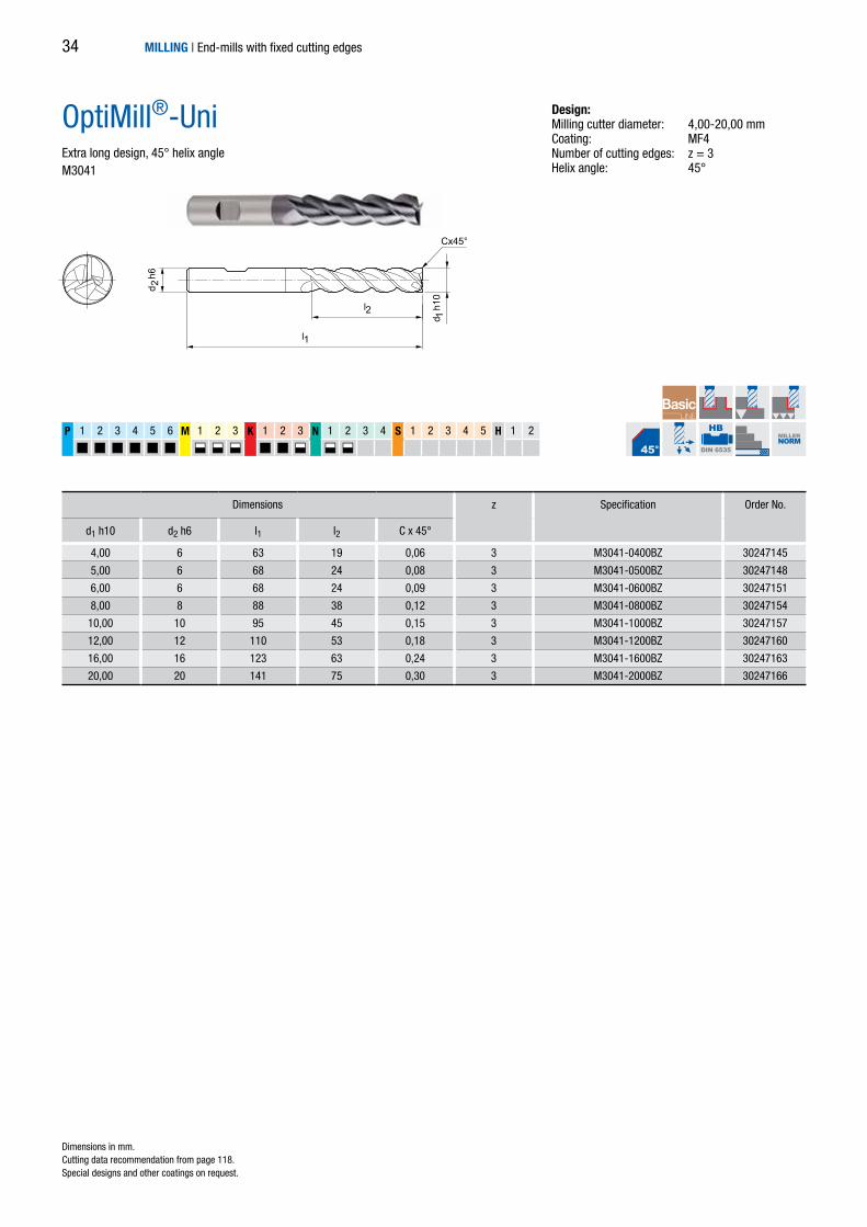
4,00 6 63 19 0,06 3 M3041-0400BZ 30247145
5,00 6 68 24 0,08 3 M3041-0500BZ 30247148
6,00 6 68 24 0,09 3 M3041-0600BZ 30247151
8,00 8 88 38 0,12 3 M3041-0800BZ 30247154
10,00 10 95 45 0,15 3 M3041-1000BZ 30247157
12,00 12 110 53 0,18 3 M3041-1200BZ 30247160
16,00 16 123 63 0,24 3 M3041-1600BZ 30247163
20,00 20 141 75 0,30 3 M3041-2000BZ 30247166
P 1 2 3 4 5 6 M 1 2 3 K 1 2 3 N 1 2 3 4 S 1 2 3 4 5 H 1 2
HB
DIN 6535
MILLERNORM
OptiMill®-UniExtra long design, 45° helix angleM3041
Design:Milling cutter diameter: 4,00-20,00 mmCoating: MF4Number of cutting edges: z = 3Helix angle: 45°
Dimensions z Specification Order No.
d1 h10 d2 h6 l1 l2 C x 45°
Dimensions in mm. Cutting data recommendation from page 118.Special designs and other coatings on request.
MILLING | End-mills with fixed cutting edges34

d 2 h
6
d 1 h
10l1
l2
l3
Cx45°
*1,00 3 38 2 – – 3 M3043-0100AZ 30247167
*1,50 3 38 3 – – 3 M3043-0150AZ 30247168
*2,00 3 54 4 – – 3 M3043-0200AZ 30247169
*2,50 6 54 6 – – 3 M3043-0250BZ 30247170
*3,00 6 57 8 – 0,05 3 M3043-0300BZ 30247142
*3,50 6 57 11 – 0,05 3 M3043-0350BZ 30247143
*4,00 6 57 11 – 0,06 3 M3043-0400BZ 30247144
*4,50 6 57 13 – 0,07 3 M3043-0450BZ 30247146
*5,00 6 57 13 – 0,08 3 M3043-0500BZ 30247147
*5,50 6 57 13 – 0,08 3 M3043-0550BZ 30247149
6,00 6 57 13 20 0,09 3 M3043-0600BZ 30247150
*7,00 8 63 16 – 0,11 3 M3043-0700BZ 30247152
8,00 8 63 19 25 0,12 3 M3043-0800BZ 30247153
*9,50 10 72 22 – 0,14 3 M3043-0950BZ 30247155
10,00 10 72 22 30 0,15 3 M3043-1000BZ 30247156
*11,00 12 83 26 – 0,17 3 M3043-1100BZ 30247158
12,00 12 83 26 36 0,18 3 M3043-1200BZ 30247159
14,00 14 83 26 36 0,21 3 M3043-1400BZ 30247161
16,00 16 92 32 42 0,24 3 M3043-1600BZ 30247162
18,00 18 92 32 42 0,27 3 M3043-1800BZ 30247164
20,00 20 104 38 55 0,30 3 M3043-2000BZ 30247165
P 1 2 3 4 5 6 M 1 2 3 K 1 2 3 N 1 2 3 4 S 1 2 3 4 5 H 1 2
HA
DIN 6535
HB
DIN 6535 DIN6527
OptiMill®-UniLong design with neck, 45° helix angleM3043
Dimensions in mm. * Design without neck.Cutting data recommendation from page 118.Special designs and other coatings on request.
Design:Milling cutter diameter: 1,00-20,00 mmCoating: MF4Number of cutting edges: z = 3Helix angle: 45°
Dimensions z Specification Order No.
d1 h10 d2 h6 l1 l2 l3 C x 45°
MILLING | End-mills with fixed cutting edges 35

d 2 h
6
l2
l3
d 1 h
10
l1
Cx45°
1,00 6 54 2,5 4 – 3 M3293-0100BN 30566813
1,50 6 54 4 6 – 3 M3293-0150BN 30486525
2,00 6 54 5 8 – 3 M3293-0200BN 30486524
2,50 6 54 6,5 10 – 3 M3293-0250BN 30566814
3,00 6 57 8 12,5 0,06 3 M3293-0300BY 30247171
4,00 6 57 11 15 0,08 3 M3293-0400BY 30247172
5,00 6 57 13 16 0,10 3 M3293-0500BY 30247173
6,00 6 57 13 20 0,12 3 M3293-0600BY 30247174
8,00 8 63 21 27 0,16 3 M3293-0800BY 30247175
10,00 10 72 22 30 0,20 3 M3293-1000BY 30247176
12,00 12 83 26 36 0,24 3 M3293-1200BY 30247177
14,00 14 83 26 36 0,28 3 M3293-1400BY 30247178
16,00 16 92 36 44 0,32 3 M3293-1600BY 30247179
18,00 18 92 36 44 0,36 3 M3293-1800BY 30247180
20,00 20 104 41 55 0,40 3 M3293-2000BY 30247181
P 1 2 3 4 5 6 M 1 2 3 K 1 2 3 N 1 2 3 4 S 1 2 3 4 5 H 1 2
HB
DIN 6535 DIN6527
OptiMill®-Uni-HPC-SlotLong design with neckM3293
Design:Milling cutter diameter: 1,00-20,00 mmCoating: MF6 (up to ø 2,50 mm) MF3 (from ø 3,00 mm)Number of cutting edges: z = 3Helix angle: 42°-43°Special features: Unequal spacing
Dimensions z Specification Order No.
d1 h10 d2 h6 l1 l2 l3 C x 45°
Dimensions in mm. Cutting data recommendation from page 118.Special designs and other coatings on request.
MILLING | End-mills with fixed cutting edges36

P 1 2 3 4 5 6 M 1 2 3 K 1 2 3 N 1 2 3 4 S 1 2 3 4 5 H 1 2
HB
DIN 6535 DIN6527
3,00 6 50 6 0,06 4 M4090-0300BD 30656917
4,00 6 54 8 0,08 4 M4090-0400BD 30656918
5,00 6 54 9 0,10 4 M4090-0500BD 30656919
6,00 6 54 10 0,12 4 M4090-0600BD 30656920
8,00 8 58 12 0,16 4 M4090-0800BD 30656921
10,00 10 66 14 0,20 4 M4090-1000BD 30656922
12,00 12 73 16 0,24 4 M4090-1200BD 30656923
14,00 14 73 16 0,28 4 M4090-1400BD 30656924
16,00 16 82 22 0,32 4 M4090-1600BD 30656925
18,00 18 82 22 0,36 4 M4090-1800BD 30656926
20,00 20 92 26 0,40 4 M4090-2000BD 30656927
d 2 h
6
l2
l1
d 1 h
10
Cx45°
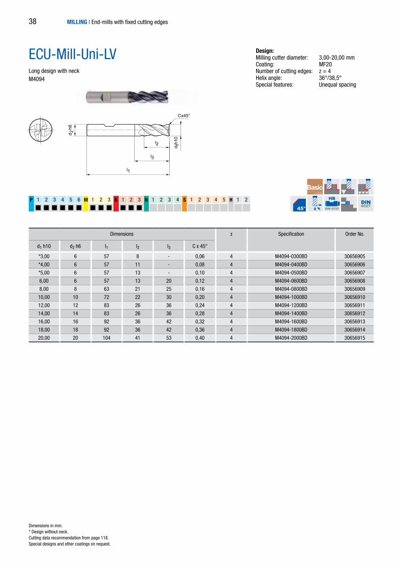
ECU-Mill-Uni-LVShort designM4090
Dimensions in mm. Cutting data recommendation from page 118.Special designs and other coatings on request.
Design:Milling cutter diameter: 3,00-20,00 mmCoating: MF20 Number of cutting edges: z = 4Helix angle: 36°/38,5°Special features: Unequal spacing
Dimensions z Specification Order No.
d1 h10 d2 h6 l1 l2 C x 45°
MILLING | End-mills with fixed cutting edges 37
P 1 2 3 4 5 6 M 1 2 3 K 1 2 3 N 1 2 3 4 S 1 2 3 4 5 H 1 2
HB
DIN 6535 DIN6527
*3,00 6 57 8 - 0,06 4 M4094-0300BD 30656905
*4,00 6 57 11 - 0,08 4 M4094-0400BD 30656906
*5,00 6 57 13 - 0,10 4 M4094-0500BD 30656907
6,00 6 57 13 20 0,12 4 M4094-0600BD 30656908
8,00 8 63 21 25 0,16 4 M4094-0800BD 30656909
10,00 10 72 22 30 0,20 4 M4094-1000BD 30656910
12,00 12 83 26 36 0,24 4 M4094-1200BD 30656911
14,00 14 83 26 36 0,28 4 M4094-1400BD 30656912
16,00 16 92 36 42 0,32 4 M4094-1600BD 30656913
18,00 18 92 36 42 0,36 4 M4094-1800BD 30656914
20,00 20 104 41 53 0,40 4 M4094-2000BD 30656915
d 2 h
6
l2
l3
d 1h1
0l1
Cx45°
ECU-Mill-Uni-LVLong design with neckM4094
Dimensions in mm. * Design without neck.Cutting data recommendation from page 118.Special designs and other coatings on request.
Design:Milling cutter diameter: 3,00-20,00 mmCoating: MF20 Number of cutting edges: z = 4Helix angle: 36°/38,5°Special features: Unequal spacing
Dimensions z Specification Order No.
d1 h10 d2 h6 l1 l2 l3 C x 45°
MILLING | End-mills with fixed cutting edges38
P 1 2 3 4 5 6 M 1 2 3 K 1 2 3 N 1 2 3 4 S 1 2 3 4 5 H 1 2
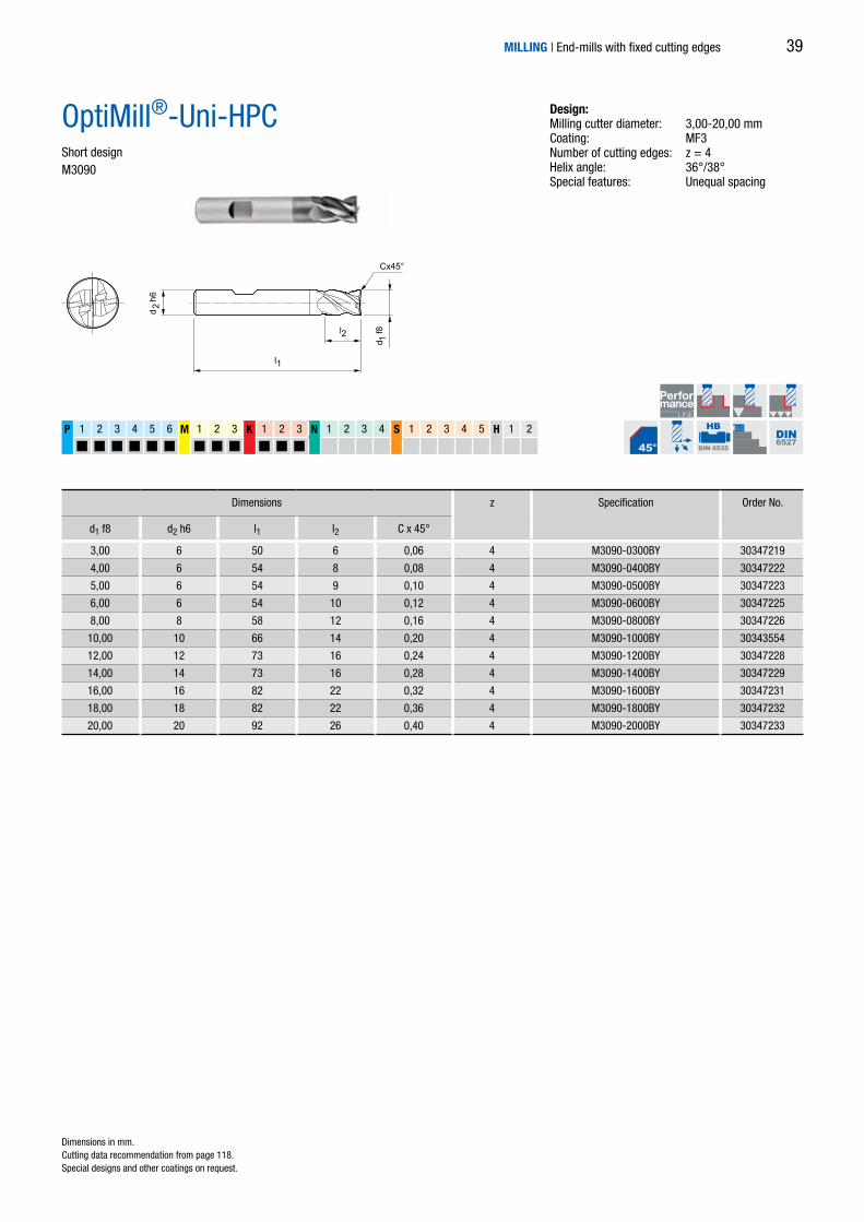
3,00 6 50 6 0,06 4 M3090-0300BY 30347219
4,00 6 54 8 0,08 4 M3090-0400BY 30347222
5,00 6 54 9 0,10 4 M3090-0500BY 30347223
6,00 6 54 10 0,12 4 M3090-0600BY 30347225
8,00 8 58 12 0,16 4 M3090-0800BY 30347226
10,00 10 66 14 0,20 4 M3090-1000BY 30343554
12,00 12 73 16 0,24 4 M3090-1200BY 30347228
14,00 14 73 16 0,28 4 M3090-1400BY 30347229
16,00 16 82 22 0,32 4 M3090-1600BY 30347231
18,00 18 82 22 0,36 4 M3090-1800BY 30347232
20,00 20 92 26 0,40 4 M3090-2000BY 30347233
HB
DIN 6535 DIN6527
d 2 h
6
l2
l1d 1
f8
Cx45°
OptiMill®-Uni-HPCShort designM3090
Design:Milling cutter diameter: 3,00-20,00 mmCoating: MF3 Number of cutting edges: z = 4Helix angle: 36°/38°Special features: Unequal spacing
Dimensions z Specification Order No.
d1 f8 d2 h6 l1 l2 C x 45°
Dimensions in mm. Cutting data recommendation from page 118.Special designs and other coatings on request.
MILLING | End-mills with fixed cutting edges 39

P 1 2 3 4 5 6 M 1 2 3 K 1 2 3 N 1 2 3 4 S 1 2 3 4 5 H 1 2
2,50 6 57 8 - - 4 M3094-0250BY 30486523
3,00 6 57 8 - 0,06 4 M3094-0300BY 30247226
4,00 6 57 11 - 0,08 4 M3094-0400BY 30247227
5,00 6 57 13 - 0,10 4 M3094-0500BY 30247228
6,00 6 57 13 20 0,12 4 M3094-0600BY 30247229
8,00 8 63 21 25 0,16 4 M3094-0800BY 30247230
10,00 10 72 22 30 0,20 4 M3094-1000BY 30247231
12,00 12 83 26 36 0,24 4 M3094-1200BY 30247232
14,00 14 83 26 36 0,28 4 M3094-1400BY 30247233
16,00 16 92 36 42 0,32 4 M3094-1600BY 30247234
18,00 18 92 36 47 0,36 4 M3094-1800BY 30247235
20,00 20 104 41 55 0,40 4 M3094-2000BY 30247236
25,00 25 136 68 80 0,50 4 M3094-2500BY 30345169
HB
DIN 6535 DIN6527
d 2 h
6
l2
l3
d 1 f8
l1
Cx45°
OptiMill®-Uni-HPCLong design with neck M3094
Design:Milling cutter diameter: 2,50-25,00 mmCoating: MF3 Number of cutting edges: z = 4Helix angle: 36°/38°Special features: Unequal spacing
Dimensions z Specification Order No.
d1 f8 d2 h6 l1 l2 l3 C x 45°
Dimensions in mm. Cutting data recommendation from page 118.Special designs and other coatings on request.
MILLING | End-mills with fixed cutting edges40

P 1 2 3 4 5 6 M 1 2 3 K 1 2 3 N 1 2 3 4 S 1 2 3 4 5 H 1 2
3,00 6 50 5 - 0,30 4 M3091-0300AY 30269832
4,00 6 50 6 - 0,30 4 M3091-0400AY 30269833
5,00 6 57 8 - 0,30 4 M3091-0500AY 30269835
6,00 6 57 9 20 0,30 4 M3091-0600AY 30269836
8,00 8 63 12 26 0,50 4 M3091-0800AY 30269837
10,00 10 72 15 32 0,50 4 M3091-1000AY 30269838
12,00 12 83 18 38 0,50 4 M3091-1200AY 30269839
16,00 16 98 24 50 1,00 4 M3091-1600AY 30269840
20,00 20 112 30 62 1,00 4 M3091-2000AY 30269841
HA
DIN 6535 DIN6527
d 2 h
6
l2
l3
d 1 h
10l1
R
OptiMill®-Uni-HPC-CRLong design with neck M3091
Design:Milling cutter diameter: 3,00-20,00 mmCoating: MF3 Number of cutting edges: z = 4Helix angle: 36°/38°Special features: Unequal spacing, with neck and corner radius
Dimensions z Specification Order No.
d1 h10 d2 h6 l1 l2 l3 R
Dimensions in mm. Cutting data recommendation from page 118.Special designs and other coatings on request.
MILLING | End-mills with fixed cutting edges 41

P 1 2 3 4 5 6 M 1 2 3 K 1 2 3 N 1 2 3 4 S 1 2 3 4 5 H 1 2
3,00 6 50 6 0,06 4 M3090P-0300BL 30673398
4,00 6 54 8 0,08 4 M3090P-0400BL 30673399
5,00 6 54 9 0,10 4 M3090P-0500BL 30673400
6,00 6 54 10 0,12 4 M3090P-0600BL 30673401
8,00 8 58 12 0,16 4 M3090P-0800BL 30673402
10,00 10 66 14 0,20 4 M3090P-1000BL 30673403
12,00 12 73 16 0,24 4 M3090P-1200BL 30673404
14,00 14 73 16 0,28 4 M3090P-1400BL 30673405
16,00 16 82 22 0,32 4 M3090P-1600BL 30673406
18,00 18 82 22 0,36 4 M3090P-1800BL 30673407
20,00 20 92 26 0,40 4 M3090P-2000BL 30673408
d 2 h
6
l2
l1
d 1 f8
Cx45°
HB
DIN 6535 DIN6527
OptiMill®-Uni-HPC-PlusShort designM3090P (follow-up product of OptiMill-Uni-HPC)
Design:Milling cutter diameter: 3,00-20,00 mmCoating: MF2 Number of cutting edges: z = 4Helix angle: 36°/38°Special features: Unequal spacing, rounded cutting edge
Dimensions z Specification Order No.
d1 f8 d2 h6 l1 l2 C x 45°
Dimensions in mm. Cutting data recommendation from page 118.Special designs and other coatings on request.
MILLING | End-mills with fixed cutting edges42

P 1 2 3 4 5 6 M 1 2 3 K 1 2 3 N 1 2 3 4 S 1 2 3 4 5 H 1 2
*2,50 6 57 8 - 0,05 4 M3094P-0250BL 30673409
*3,00 6 57 8 - 0,06 4 M3094P-0300BL 30673410
*4,00 6 57 11 - 0,08 4 M3094P-0400BL 30673411
*5,00 6 57 13 - 0,10 4 M3094P-0500BL 30673412
6,00 6 57 13 20 0,12 4 M3094P-0600BL 30673413
7,00 8 63 16 25 0,14 4 M3094P-0700BL 30673414
8,00 8 63 21 25 0,16 4 M3094P-0800BL 30673415
9,00 10 72 22 30 0,18 4 M3094P-0900BL 30673416
10,00 10 72 22 30 0,20 4 M3094P-1000BL 30673417
12,00 12 83 26 36 0,24 4 M3094P-1200BL 30673418
14,00 14 83 26 36 0,28 4 M3094P-1400BL 30673419
16,00 16 92 36 42 0,32 4 M3094P-1600BL 30673420
18,00 18 92 36 47 0,36 4 M3094P-1800BL 30673421
20,00 20 104 41 55 0,40 4 M3094P-2000BL 30673422
25,00 25 136 68 80 0,50 4 M3094P-2500BL 30673423
d 2 h
6
l2
l3
d 1 f8
l1
Cx45°
HB
DIN 6535 DIN6527
OptiMill®-Uni-HPC-PlusLong design with neck M3094P (follow-up product of OptiMill-Uni-HPC)
Design:Milling cutter diameter: 2,50-25,00 mmCoating: MF2 Number of cutting edges: z = 4Helix angle: 36°/38°Special features: Unequal spacing, rounded cutting edge
Dimensions z Specification Order No.
d1 f8 d2 h6 l1 l2 l3 C x 45°
* Design without neck.Dimensions in mm. Cutting data recommendation from page 118.Special designs and other coatings on request.
MILLING | End-mills with fixed cutting edges 43

5,00 6 62 13 24 0,10 4 M3190P-0500BL 30636550
6,00 6 62 13 25 0,12 4 M3190P-0600BL 30636585
8,00 8 68 21 30 0,16 4 M3190P-0800BL 30636586
10,00 10 80 22 38 0,20 4 M3190P-1000BL 30636588
12,00 12 93 26 46 0,24 4 M3190P-1200BL 30636590
14,00 14 99 26 52 0,28 4 M3190P-1400BL 30636591
16,00 16 108 36 58 0,32 4 M3190P-1600BL 30636592
18,00 18 117 36 67 0,36 4 M3190P-1800BL 30651264
20,00 20 126 41 74 0,40 4 M3190P-2000BL 30636594
25,00 25 150 50 92 0,50 4 M3190P-2500BL 30636595
P 1 2 3 4 5 6 M 1 2 3 K 1 2 3 N 1 2 3 4 S 1 2 3 4 5 H 1 2
d 2 h
6
l2
l3
d 1 f8
l1
Cx45°
HB
DIN 6535
MILLERNORM
OptiMill®-Uni-HPC-PlusOverlong design with neckM3190P
Design:Milling cutter diameter: 5,00-25,00 mmCoating: MF2Number of cutting edges: z = 4Helix angle: 36°/38° Special features: Unequal spacing, rounded cutting edge
Dimensions z Specification
d1 f8 d2 h6 l1 l2 l3 C x 45° Order No.
Dimensions in mm. Cutting data recommendation from page 118.Special designs and other coatings on request.
MILLING | End-mills with fixed cutting edges44

5,00 6 80 13 41 0,10 4 M3194P-0500BL 30652455
6,00 6 80 13 42 0,12 4 M3194P-0600BL 30652456
8,00 8 100 21 62 0,16 4 M3194P-0800BL 30652457
10,00 10 100 22 58 0,20 4 M3194P-1000BL 30652458
12,00 12 120 26 73 0,24 4 M3194P-1200BL 30652459
14,00 14 120 26 73 0,28 4 M3194P-1400BL 30652461
16,00 16 150 36 100 0,32 4 M3194P-1600BL 30652462
18,00 18 150 36 100 0,36 4 M3194P-1800BL 30652463
20,00 20 150 41 98 0,40 4 M3194P-2000BL 30652464
25,00 25 175 50 117 0,50 4 M3194P-2500BL 30652465
P 1 2 3 4 5 6 M 1 2 3 K 1 2 3 N 1 2 3 4 S 1 2 3 4 5 H 1 2
d 2 h
6
l2
l3
d 1 f8
l1
Cx45°
HB
DIN 6535
MILLERNORM
OptiMill®-Uni-HPC-PlusExtra long design with neckM3194P
Design:Milling cutter diameter: 5,00-25,00 mmCoating: MF2Number of cutting edges: z = 4Helix angle: 36°/38° Special features: Unequal spacing, rounded cutting edge
Dimensions z Specification Order No.
d1 f8 d2 h6 l1 l2 l3 C x 45°
Dimensions in mm. Cutting data recommendation from page 118.Special designs and other coatings on request.
MILLING | End-mills with fixed cutting edges 45

d 2 h
6
l2
l3
d 1 f8
l1
Cx45°
P 1 2 3 4 5 6 M 1 2 3 K 1 2 3 N 1 2 3 4 S 1 2 3 4 5 H 1 2
6,00 6 57 13 20 0,12 5 M3095-0600BL 30479500
8,00 8 63 19 25 0,16 5 M3095-0800BL 30482153
10,00 10 72 22 30 0,20 5 M3095-1000BL 30482154
12,00 12 83 26 36 0,24 5 M3095-1200BL 30482155
14,00 14 83 26 36 0,28 5 M3095-1400BL 30491448
16,00 16 92 32 42 0,32 5 M3095-1600BL 30482156
18,00 18 92 32 42 0,36 5 M3095-1800BL 30491450
20,00 20 104 41 52 0,40 5 M3095-2000BL 30482157
25,00 25 125 50 65 0,50 5 M3095-2500BL 30482158
HB
DIN 6535 DIN6527
OptiMill®-Uni-HPC-SilentLong design with neckM3095
Design:Milling cutter diameter: 6,00-25,00 mmCoating: MF2Number of cutting edges: z = 5Helix angle: 41°-42°Special features: Unequal spacing
Dimensions z Specification Order No.
d1 f8 d2 h6 l1 l2 l3 C x 45°
Dimensions in mm. Cutting data recommendation from page 118.Special designs and other coatings on request.
MILLING | End-mills with fixed cutting edges46
d 2 h
6
l2
l1
d 1 h
10
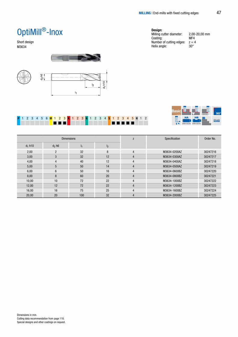
2,00 2 32 8 4 M3634-0200AZ 30247216
3,00 3 32 12 4 M3634-0300AZ 30247217
4,00 4 40 12 4 M3634-0400AZ 30247218
5,00 5 50 14 4 M3634-0500AZ 30247219
6,00 6 50 16 4 M3634-0600BZ 30247220
8,00 8 60 20 4 M3634-0800BZ 30247221
10,00 10 72 22 4 M3634-1000BZ 30247222
12,00 12 72 22 4 M3634-1200BZ 30247223
16,00 16 75 25 4 M3634-1600BZ 30247224
20,00 20 100 32 4 M3634-2000BZ 30247225
P 1 2 3 4 5 6 M 1 2 3 K 1 2 3 N 1 2 3 4 S 1 2 3 4 5 H 1 2
HA
DIN 6535
HB
DIN 6535
MILLERNORM
OptiMill®-InoxShort designM3634
Design:Milling cutter diameter: 2,00-20,00 mmCoating: MF4Number of cutting edges: z = 4Helix angle: 30°
Dimensions z Specification Order No.
d1 h10 d2 h6 l1 l2
Dimensions in mm. Cutting data recommendation from page 118.Special designs and other coatings on request.
MILLING | End-mills with fixed cutting edges 47

d 2 h
6
l2
l3
d 1 h
10
l1
Cx45° / R
P 1 2 3 4 5 6 M 1 2 3 K 1 2 3 N 1 2 3 4 S 1 2 3 4 5 H 1 2
6,00 6 57 13 20 0,12 – 4 M3694-0600BU-C0012 30395299
6,00 6 57 13 20 – 0,50 4 M3694-0600BU-R0050 30395300
8,00 8 63 19 25 0,16 – 4 M3694-0800BU-C0016 30395305
8,00 8 63 19 25 – 0,50 4 M3694-0800BU-R0050 30395306
10,00 10 72 22 30 0,20 – 4 M3694-1000BU-C0020 30395307
10,00 10 72 22 30 – 0,50 4 M3694-1000BU-R0050 30395308
10,00 10 72 22 30 – 1,00 4 M3694-1000BU-R0100 30395309
12,00 12 83 26 36 0,24 – 4 M3694-1200BU-C0024 30395313
12,00 12 83 26 36 – 0,50 4 M3694-1200BU-R0050 30395316
12,00 12 83 26 36 – 1,00 4 M3694-1200BU-R0100 30395319
12,00 12 83 26 36 – 1,50 4 M3694-1200BU-R0150 30395320
14,00 14 83 26 36 0,28 – 4 M3694-1400BU-C0028 30395321
14,00 14 83 26 36 – 1,00 4 M3694-1400BU-R0100 30395322
16,00 16 92 36 42 0,32 – 4 M3694-1600BU-C0032 30395325
16,00 16 92 36 42 – 1,00 4 M3694-1600BU-R0100 30395327
16,00 16 92 36 42 – 1,50 4 M3694-1600BU-R0150 30395328
16,00 16 92 36 42 – 2,00 4 M3694-1600BU-R0200 30395329
20,00 20 104 41 52 0,40 – 4 M3694-2000BU-C0040 30395330
20,00 20 104 41 52 – 1,50 4 M3694-2000BU-R0150 30395332
20,00 20 104 41 52 – 2,00 4 M3694-2000BU-R0200 30395334
20,00 20 104 41 52 – 2,50 4 M3694-2000BU-R0250 30395336
HB
DIN 6535 DIN6527
Dimensions z Specification Order No.
d1 h10 d2 h6 l1 l2 l3 C x 45° R
OptiMill®-Titan-HPCLong design with neckM3694
Design:Milling cutter diameter: 6,00-20,00 mmCoating: UncoatedNumber of cutting edges: z = 4Helix angle: ~ 39°
Dimensions in mm. Cutting data recommendation from page 118.Special designs and other coatings on request.
MILLING | End-mills with fixed cutting edges48
P 1 2 3 4 5 6 M 1 2 3 K 1 2 3 N 1 2 3 4 S 1 2 3 4 5 H 1 2
d 2 h
6
l2
l3
d 1 h
10
l1
Cx45° / R
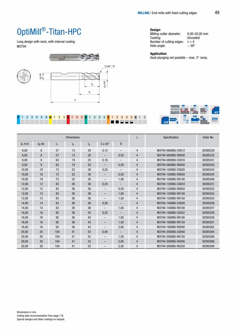
6,00 6 57 13 20 0,12 – 4 M3794-0600BU-C0012 30395230
6,00 6 57 13 20 – 0,50 4 M3794-0600BU-R0050 30395235
8,00 8 63 19 25 0,16 – 4 M3794-0800BU-C0016 30395241
8,00 8 63 19 25 – 0,50 4 M3794-0800BU-R0050 30395242
10,00 10 72 22 30 0,20 – 4 M3794-1000BU-C0020 30395243
10,00 10 72 22 30 – 0,50 4 M3794-1000BU-R0050 30395245
10,00 10 72 22 30 – 1,00 4 M3794-1000BU-R0100 30395246
12,00 12 83 26 36 0,24 – 4 M3794-1200BU-C0024 30395251
12,00 12 83 26 36 – 0,50 4 M3794-1200BU-R0050 30395252
12,00 12 83 26 36 – 1,00 4 M3794-1200BU-R0100 30395254
12,00 12 83 26 36 – 1,50 4 M3794-1200BU-R0150 30395255
14,00 14 83 26 36 0,28 – 4 M3794-1400BU-C0028 30395256
14,00 14 83 26 36 – 1,00 4 M3794-1400BU-R0100 30395257
16,00 16 92 36 42 0,32 – 4 M3794-1600BU-C0032 30395258
16,00 16 92 36 42 – 1,00 4 M3794-1600BU-R0100 30395259
16,00 16 92 36 42 – 1,50 4 M3794-1600BU-R0150 30395261
16,00 16 92 36 42 – 2,00 4 M3794-1600BU-R0200 30395262
20,00 20 104 41 52 0,40 – 4 M3794-2000BU-C0040 30395264
20,00 20 104 41 52 – 1,50 4 M3794-2000BU-R0150 30395266
20,00 20 104 41 52 – 2,00 4 M3794-2000BU-R0200 30395268
20,00 20 104 41 52 – 2,50 4 M3794-2000BU-R0250 30395269
HB
DIN 6535 DIN6527
Dimensions z Specification Order No.
d1 h10 d2 h6 l1 l2 l3 C x 45° R
OptiMill®-Titan-HPCLong design with neck, with internal coolingM3794
Dimensions in mm. Cutting data recommendation from page 118.Special designs and other coatings on request.
MILLING | End-mills with fixed cutting edges
Design:Milling cutter diameter: 6,00-20,00 mmCoating: UncoatedNumber of cutting edges: z = 4Helix angle: ~ 39°
Application: Axial plunging not possible – max. 3° ramp.
49

N 1.1 1.2 1.3 1.4 2.1 2.2 2.3 3.1 4.1 4.2 4.3 C 1.1 1.2 1.3 2.1 3.1 4.1 4.2 4.3 4.4 5.1 5.2
d 2
d 1l2
l1
HA
DIN 6535
MILLERNORM
2,00 3 38 5 1 MN7MA1A0200 30253284
2,50 3 38 6 1 MN7MA1A0250 30230396
3,00 3 38 8 1 MN7MA1A0300 30218904
3,00 4 38 8 1 MN7MA1B0300 30218905
3,17 3,17 38 8 1 MN7MA1A0317 30218906
3,17 4,76 38 8 1 MN7MA1B0317 30218907
3,17 6,35 38 8 1 MN7MA1C0317 30218908
4,00 4 40 12 1 MN7MA1A0400 30218919
4,00 4 70 30 1 MN7MA1B0400 30218920
4,00 6 50 10 1 MN7MA1C0400 30218921
4,76 4,76 51 13 1 MN7MA1A0476 30218922
4,76 6,35 51 13 1 MN7MA1B0476 30230397
5,00 5 60 15 1 MN7MA1A0500 30218923
5,00 5 70 30 1 MN7MA1B0500 30218924
5,00 6 50 12 1 MN7MA1C0500 30218925
6,00 6 60 20 1 MN7MA1A0600 30218926
6,00 6 70 30 1 MN7MA1B0600 30218927
6,00 6 80 38 1 MN7MA1C0600 30218928
6,00 6 70 15 1 MN7MA1D0600 30218929
6,00 6 50 12 1 MN7MA1E0600 30218930
6,35 6,35 51 16 1 MN7MA1A0635 30218931
8,00 8 60 20 1 MN7MA1A0800 30218932
8,00 8 80 38 1 MN7MA1B0800 30218933
10,00 10 75 30 1 MN7MA1A1000 30218934
10,00 10 60 25 1 MN7MA1B1000 30218935
10,00 10 100 25 1 MN7MA1C1000 30218936
10,00 12 90 25 1 MN7MA1D1000 30218937
12,70 12,70 89 29 1 MN7MA1A1270 30218938
OptiMill®-Mono-AluDifferent designs, right-hand helix groove Type 200R
Design:Milling cutter diameter: 2,00-12,70 mmCoating: UncoatedNumber of cutting edges: z = 1 Helix angle: 30°
Dimensions z Specification Order No.
d1 d2 l1 l2
Dimensions in mm. Cutting data recommendation from page 118.Special designs and other coatings on request.
MILLING | End-mills with fixed cutting edges50

N 1.1 1.2 1.3 1.4 2.1 2.2 2.3 3.1 4.1 4.2 4.3 C 1.1 1.2 1.3 2.1 3.1 4.1 4.2 4.3 4.4 5.1 5.2
d 2
d 1l2
l1
HA
DIN 6535
MILLERNORM
2,50 3 38 6 1 MN7MA2A0250 30230591
3,00 4 38 8 1 MN7MA2A0300 30230592
3,17 6,35 38 8 1 MN7MA2A0317 30230596
4,00 4 40 12 1 MN7MA2A0400 30230597
4,00 6 50 10 1 MN7MA2B0400 30230601
4,76 6,35 51 13 1 MN7MA2A0476 30230603
5,00 5 60 15 1 MN7MA2A0500 30230608
5,00 6 50 12 1 MN7MA2B0500 30230609
6,00 6 60 15 1 MN7MA2A0600 30230611
6,35 6,35 51 16 1 MN7MA2A0635 30230614
8,00 8 60 20 1 MN7MA2A0800 30230616
10,00 10 60 25 1 MN7MA2A1000 30230618
OptiMill®-Mono-AluDifferent designs, left-hand helix groove Type 200L
Design:Milling cutter diameter: 2,50-10,00 mmCoating: UncoatedNumber of cutting edges: z = 1 Helix angle: 30°
Dimensions z Specification Order No.
d1 d2 l1 l2
Dimensions in mm. Cutting data recommendation from page 118.Special designs and other coatings on request.
MILLING | End-mills with fixed cutting edges 51

5,00 6 4,9 70 20 30 1,00 1 MN7MA3A0500 30237645
6,00 8 5,6 80 20 35 1,50 1 MN7MA3A0600 30237646
8,00 10 7,6 90 22 45 1,50 1 MN7MA3A0800 30237647
10,00 10 9,5 100 25 50 2,00 1 MN7MA3A1000 30237649
10,00 12 9,5 90 25 50 2,00 1 MN7MA3A1000 30237650
12,00 12 11,5 120 30 60 2,50 1 MN7MA3A1200 30237651
N 1.1 1.2 1.3 1.4 2.1 2.2 2.3 3.1 4.1 4.2 4.3 C 1.1 1.2 1.3 2.1 3.1 4.1 4.2 4.3 4.4 5.1 5.2
d 2
d 1
l2
l1
l3
d 3
R
HA
DIN 6535
MILLERNORM
OptiMill®-Mono-AluDifferent designs with neck and corner radius, right-hand helix groove Type 200RY
Design:Milling cutter diameter: 5,00-12,00 mmCoating: UncoatedNumber of cutting edges: z = 1 Helix angle: 30°
Dimensions z Specification Order No.
d1 d2 d3 l1 l2 l3 R
Dimensions in mm. Cutting data recommendation from page 118.Special designs and other coatings on request.
MILLING | End-mills with fixed cutting edges52
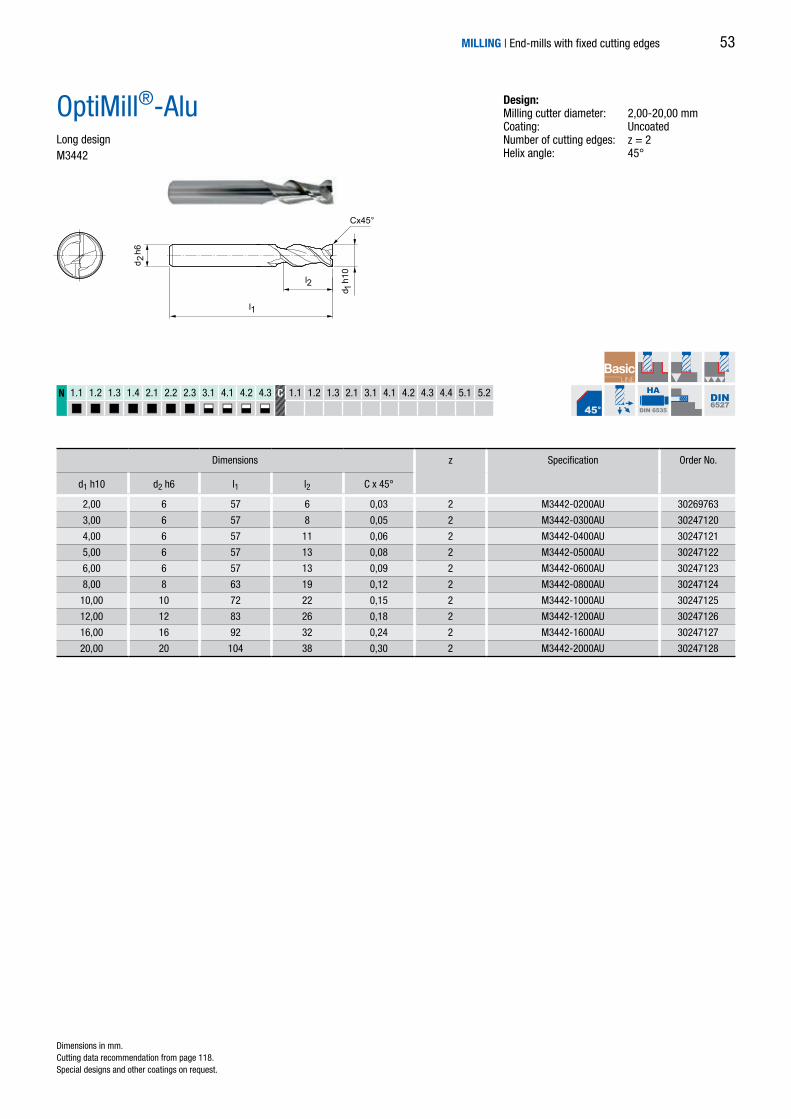
2,00 6 57 6 0,03 2 M3442-0200AU 30269763
3,00 6 57 8 0,05 2 M3442-0300AU 30247120
4,00 6 57 11 0,06 2 M3442-0400AU 30247121
5,00 6 57 13 0,08 2 M3442-0500AU 30247122
6,00 6 57 13 0,09 2 M3442-0600AU 30247123
8,00 8 63 19 0,12 2 M3442-0800AU 30247124
10,00 10 72 22 0,15 2 M3442-1000AU 30247125
12,00 12 83 26 0,18 2 M3442-1200AU 30247126
16,00 16 92 32 0,24 2 M3442-1600AU 30247127
20,00 20 104 38 0,30 2 M3442-2000AU 30247128
N 1.1 1.2 1.3 1.4 2.1 2.2 2.3 3.1 4.1 4.2 4.3 C 1.1 1.2 1.3 2.1 3.1 4.1 4.2 4.3 4.4 5.1 5.2
d 2 h
6
l2
l1
d 1 h
10
Cx45°
HA
DIN 6535 DIN6527
OptiMill®-AluLong designM3442
Design:Milling cutter diameter: 2,00-20,00 mmCoating: UncoatedNumber of cutting edges: z = 2Helix angle: 45°
Dimensions z Specification Order No.
d1 h10 d2 h6 l1 l2 C x 45°
Dimensions in mm. Cutting data recommendation from page 118.Special designs and other coatings on request.
MILLING | End-mills with fixed cutting edges 53

d 2 h
6
l2
l3
d 1 h
10
l1
Cx45°
*3,00 6 57 8 – 0,06 3 M3493-0300BU 30248238
*4,00 6 57 11 – 0,08 3 M3493-0400BU 30248241
*5,00 6 57 13 – 0,10 3 M3493-0500BU 30248242
6,00 6 57 13 18 0,12 3 M3493-0600BU 30248243
8,00 8 63 21 25 0,16 3 M3493-0800BU 30248244
10,00 10 72 22 30 0,20 3 M3493-1000BU 30248245
12,00 12 83 26 36 0,24 3 M3493-1200BU 30248246
16,00 16 92 36 42 0,32 3 M3493-1600BU 30248247
20,00 20 104 41 52 0,40 3 M3493-2000BU 30248248
N 1.1 1.2 1.3 1.4 2.1 2.2 2.3 3.1 4.1 4.2 4.3 C 1.1 1.2 1.3 2.1 3.1 4.1 4.2 4.3 4.4 5.1 5.2
HB
DIN 6535 DIN6527
OptiMill®-Alu-HPCLong design with neckM3493
Design:Milling cutter diameter: 3,00-20,00 mmCoating: UncoatedNumber of cutting edges: z = 3, Helix angle: 42°-43°Special features: Unequal spacing, grooves polished
Dimensions z Specification Order No.
d1 h10 d2 h6 l1 l2 l3 C x 45°
Dimensions in mm. * Design without neck.Cutting data recommendation from page 118.Special designs and other coatings on request.
MILLING | End-mills with fixed cutting edges54

l2
R
l1
d 2 h
6
d 1f9
l3
14,00 16 77 11,2 24,5 3,00 3 M3593-1400AU 30612310
15,00 16 78 12 26,25 3,00 3 M3593-1500AU 30612311
16,00 16 81 12,8 28 3,00 3 M3593-1600AU 30612312
18,00 20 87 14,4 31,5 3,00 3 M3593-1800AU 30612313
20,00 20 90 16 35 3,00 3 M3593-2000AU 30612314
25,00 25 107 20 43,75 4,00 3 M3593-2500AU 30612315
32,00 32 125 25,6 56 4,00 3 M3593-3200AU 30612316
6,00 6 60 4,8 19,5 1,00 3 M3591-0600AU 30612317
8,00 8 70 6,4 26 1,00 3 M3591-0800AU 30612318
10,00 10 80 8 32,5 2,00 3 M3591-1000AU 30612319
12,00 12 90 9,6 39 2,00 3 M3591-1200AU 30612320
14,00 16 99 11,2 45,5 3,00 3 M3591-1400AU 30612321
15,00 16 100 12 48,75 3,00 3 M3591-1500AU 30612322
16,00 16 105 12,8 52 3,00 3 M3591-1600AU 30612323
18,00 20 114 14,4 58,5 3,00 3 M3591-1800AU 30612324
20,00 20 120 16 65 3,00 3 M3591-2000AU 30612325
25,00 25 145 20 81,25 4,00 3 M3591-2500AU 30612326
32,00 32 173 25,6 104 4,00 3 M3591-3200AU 30612327
N 1.1 1.2 1.3 1.4 2.1 2.2 2.3 3.1 4.1 4.2 4.3 C 1.1 1.2 1.3 2.1 3.1 4.1 4.2 4.3 4.4 5.1 5.2
HA
DIN 6535
MILLERNORM
Dimensions z Specification Order No.
d1 f9 d2 h6 l1 l2 l3 R
OptiMill®-Volume-NDifferent designs with internal cooling M3591/M3593
Design:Milling cutter diameter: 6,00-32,00 mmCoating: UncoatedNumber of cutting edges: z = 3Helix angle: 43°
Application: For machining of structural parts made of aluminium.
Short design | M3593
Long design | M3591
Dimensions in mm. Cutting data recommendation from page 118.Special designs and other coatings on request.
MILLING | End-mills with fixed cutting edges 55

N 1.1 1.2 1.3 1.4 2.1 2.2 2.3 3.1 4.1 4.2 4.3 C 1.1 1.2 1.3 2.1 3.1 4.1 4.2 4.3 4.4 5.1 5.2
l2
l1
d 2
d 1
HA
DIN 6535
MILLERNORM
2,00 3 38 8 1 MN7MP1A0200 30253277
2,50 3 38 8 1 MN7MP1A0250 30230388
3,00 3 38 10 1 MN7MP1A0300 30216602
3,00 4 38 10 1 MN7MP1B0300 30216609
3,00 4 50 15 1 MN7MP1C0300 30216610
3,00 6 50 10 1 MN7MP1D0300 30216611
3,17 6,35 38 13 1 MN7MP1A0317 30216612
3,17 4,76 38 13 1 MN7MP1B0317 30216613
3,17 3,17 51 13 1 MN7MP1C0317 30216614
4,00 4 40 12 1 MN7MP1A0400 30216615
4,00 4 60 20 1 MN7MP1B0400 30216616
4,00 4 70 30 1 MN7MP1C0400 30216617
4,00 6 50 15 1 MN7MP1D0400 30216618
4,00 4 50 13 1 MN7MP1E0400 30230389
4,76 4,76 51 16 1 MN7MP1A0476 30216619
5,00 5 50 16 1 MN7MP1A0500 30216620
5,00 5 70 30 1 MN7MP1B0500 30216621
5,00 5 60 15 1 MN7MP1C0500 30230390
5,00 6 50 16 1 MN7MP1D0500 30231256
6,00 6 60 21 1 MN7MP1A0600 30216622
6,00 6 70 30 1 MN7MP1B0600 30216623
6,00 6 80 38 1 MN7MP1C0600 30216624
6,35 6,35 51 19 1 MN7MP1A0635 30216625
6,35 6,35 77 38 1 MN7MP1B0635 30216626
8,00 8 60 25 1 MN7MP1A0800 30216627
8,00 8 80 38 1 MN7MP1B0800 30216628
9,52 9,52 77 29 1 MN7MP1A0952 30274466
10,00 10 75 30 1 MN7MP1A1000 30216629
10,00 10 75 20 1 MN7MP1B1000 30219773
12,00 12 75 30 1 MN7MP1A1200 30216630
12,70 12,7 77 32 1 MN7MP1A1270 30216632
OptiMill®-Mono-PlasticDifferent designs, right-hand helix grooveType 100R
Design:Milling cutter diameter: 2,00-12,70 mmCoating: UncoatedNumber of cutting edges: z = 1
Dimensions z Specification Order No.
d1 d2 l1 l2
Dimensions in mm. Cutting data recommendation from page 118.Special designs and other coatings on request.
MILLING | End-mills with fixed cutting edges56

N 1.1 1.2 1.3 1.4 2.1 2.2 2.3 3.1 4.1 4.2 4.3 C 1.1 1.2 1.3 2.1 3.1 4.1 4.2 4.3 4.4 5.1 5.2
l2
l1
d 2
d 1
HA
DIN 6535
MILLERNORM
2,00 3 38 8 1 MN7MP2A0200 30253278
2,50 3 38 8 1 MN7MP2A0250 30230391
3,00 3 38 10 1 MN7MP2A0300 30216634
3,00 4 38 10 1 MN7MP2B0300 30216636
3,00 4 50 15 1 MN7MP2C0300 30216637
3,00 6 50 10 1 MN7MP2D0300 30216638
3,17 6,35 38 13 1 MN7MP2A0317 30216640
4,00 4 40 12 1 MN7MP2A0400 30216641
4,00 4 60 20 1 MN7MP2B0400 30216642
4,00 4 70 30 1 MN7MP2C0400 30216643
4,00 6 50 15 1 MN7MP2D0400 30216644
4,00 4 50 13 1 MN7MP2E0400 30230392
4,76 4,76 51 16 1 MN7MP2A0476 30216645
4,76 6,35 51 16 1 MN7MP2B0476 30274465
5,00 5 50 16 1 MN7MP2A0500 30216646
5,00 5 70 30 1 MN7MP2B0500 30231254
5,00 5 60 15 1 MN7MP2C0500 30230393
6,00 6 60 20 1 MN7MP2A0600 30216647
6,00 6 70 30 1 MN7MP2B0600 30216648
6,00 6 80 38 1 MN7MP2C0600 30230394
6,35 6,35 51 19 1 MN7MP2A0635 30216649
8,00 8 60 25 1 MN7MP2A0800 30216650
8,00 8 80 38 1 MN7MP2B0800 30230395
10,00 10 75 30 1 MN7MP2A1000 30216651
10,00 10 75 20 1 MN7MP2B1000 30216652
OptiMill®-Mono-PlasticDifferent designs, left-hand helix groove Type 100L
Design:Milling cutter diameter: 2,00-10,00 mmCoating: UncoatedNumber of cutting edges: z = 1
Dimensions z Specification Order No.
d1 d2 l1 l2
Dimensions in mm. Cutting data recommendation from page 118.Special designs and other coatings on request.
MILLING | End-mills with fixed cutting edges 57

4,00 4 60 25 4 M7624-0400AU 30313788
6,00 6 64,7 30 4 M7624-0600AU 30291377
8,00 8 75 30 4 M7624-0800AU 30313789
12,00 12 83 32 4 M7624-1200AU 30313790
16,00 16 92 36 4 M7624-1600AU 30313791
d 2h6
d 1h1
0
l2
l1
N 1.1 1.2 1.3 1.4 2.1 2.2 2.3 3.1 4.1 4.2 4.3 C 1.1 1.2 1.3 2.1 3.1 4.1 4.2 4.3 4.4 5.1 5.2
HA
DIN 6535
MILLERNORM
OptiMill®-SoftfoamLong designM7624
Dimensions z Specification Order No.
d1 h10 d2 h6 l1 l2
Dimensions in mm. Cutting data recommendation from page 118.Special designs and other coatings on request.
MILLING | End-mills with fixed cutting edges
Design:Milling cutter diameter: 4,00-16,00 mmCoating: UncoatedNumber of cutting edges: z = 4Helix angle: 6°
Application: Especially for milling soft foam.
58
Cx45°
l2
l1
d 1h1
0
d 2h6
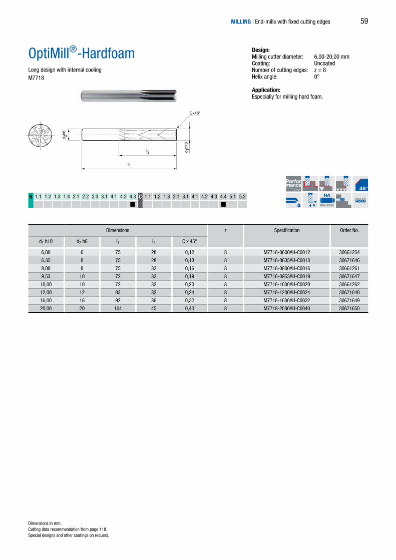
6,00 6 75 28 0,12 8 M7718-0600AU-C0012 30661254
6,35 8 75 28 0,13 8 M7718-0635AU-C0013 30671646
8,00 8 75 32 0,16 8 M7718-0800AU-C0016 30661261
9,53 10 72 32 0,19 8 M7718-0953AU-C0019 30671647
10,00 10 72 32 0,20 8 M7718-1000AU-C0020 30661262
12,00 12 83 32 0,24 8 M7718-1200AU-C0024 30671648
16,00 16 92 36 0,32 8 M7718-1600AU-C0032 30671649
20,00 20 104 45 0,40 8 M7718-2000AU-C0040 30671650
N 1.1 1.2 1.3 1.4 2.1 2.2 2.3 3.1 4.1 4.2 4.3 C 1.1 1.2 1.3 2.1 3.1 4.1 4.2 4.3 4.4 5.1 5.2
HA
DIN 6535
MILLERNORM
OptiMill®-HardfoamLong design with internal cooling M7718
Dimensions z Specification Order No.
d1 h10 d2 h6 l1 l2 C x 45°
Dimensions in mm. Cutting data recommendation from page 118.Special designs and other coatings on request.
MILLING | End-mills with fixed cutting edges
Design:Milling cutter diameter: 6,00-20,00 mmCoating: UncoatedNumber of cutting edges: z = 8Helix angle: 0°
Application: Especially for milling hard foam.
59

3,00 6 62 8 0,03 4 M7614-0300AU-C0003 30671651
4,00 6 62 11 0,04 4 M7614-0400AU-C0004 30661232
5,00 6 62 13 0,05 4 M7614-0500AU-C0005 30671652
6,00 6 62 13 0,06 4 M7614-0600AU-C0006 30661233
6,35 8 68 15 0,06 4 M7614-0635AU-C0006 30671653
8,00 8 68 19 0,08 4 M7614-0800AU-C0008 30661235
9,53 10 80 22 0,10 4 M7614-0953AU-C0010 30671654
10,00 10 80 22 0,10 4 M7614-1000AU-C0010 30661228
12,00 12 93 26 0,12 4 M7614-1200AU-C0012 30671655
16,00 16 108 32 0,16 4 M7614-1600AU-C0016 30671656
20,00 20 126 38 0,20 4 M7614-2000AU-C0020 30671657
l2
l1
d 2h6
d 1h1
0
Cx45°
N 1.1 1.2 1.3 1.4 2.1 2.2 2.3 3.1 4.1 4.2 4.3 C 1.1 1.2 1.3 2.1 3.1 4.1 4.2 4.3 4.4 5.1 5.2
HA
DIN 6535
MILLERNORM
MILLING | End-mills with fixed cutting edges
OptiMill®-ThermoplasticOverlong design M7614
Dimensions z Specification Order No.
d1 h10 d2 h6 l1 l2 C x 45°
Dimensions in mm. Cutting data recommendation from page 118.Special designs and other coatings on request.
Design:Milling cutter diameter: 3,00-20,00 mmCoating: UncoatedNumber of cutting edges: z = 4Helix angle: 0°/3°
Application: Especially for milling thermoplastics. Very sharp cutting edges reduce the heat produced during milling to a minimum and ensure optimal removal of the chips.
60

4,00 6 62 11 0,08 4 M7644-0400AQ-C0008 30661550
5,00 6 62 13 0,10 4 M7644-0500AQ-C0010 30661551
6,00 6 62 13 0,12 4 M7644-0600AQ-C0012 30661552
6,35 8 68 15 0,13 4 M7644-0635AQ-C0013 30661554
8,00 8 68 19 0,16 4 M7644-0800AQ-C0016 30661555
9,53 10 80 22 0,19 4 M7644-0953AQ-C0019 30661556
10,00 10 80 22 0,20 4 M7644-1000AQ-C0020 30661557
12,00 12 93 26 0,24 4 M7644-1200AQ-C0024 30661558
16,00 16 108 32 0,32 4 M7644-1600AQ-C0032 30661559
20,00 20 126 38 0,40 4 M7644-2000AQ-C0040 30661560
l2
l1
d 2h6
Cx45°
d 1h1
0
N 1.1 1.2 1.3 1.4 2.1 2.2 2.3 3.1 4.1 4.2 4.3 C 1.1 1.2 1.3 2.1 3.1 4.1 4.2 4.3 4.4 5.1 5.2
HA
DIN 6535
MILLERNORM
MILLING | End-mills with fixed cutting edges
OptiMill®-Thermoplastic-FROverlong design M7644
Dimensions z Specification Order No.
d1 h10 d2 h6 l1 l2 C x 45°
Dimensions in mm. Cutting data recommendation from page 118.Special designs and other coatings on request.
Design:Milling cutter diameter: 4,00-20,00 mmCoating: Diamond coatingNumber of cutting edges: z = 4Helix angle: 0°Special features: Diamond coating for long tool life
Application: For the cost-effective machining of thermoplastics with fibre reinforcement. Due to special high-perfor-mance teeth, the fibres are cut cleanly at the cuttingedge without burr formation.
61

4,00 4 50 16 Vielzahn M7001-0400AU 30290439
5,00 5 50 16 Vielzahn M7001-0500AU 30290440
5,00 5 75 16 Vielzahn M7001-0500AU 30290441
6,00 6 60 19 Vielzahn M7001-0600AU 30290442
6,00 6 75 30 Vielzahn M7001-0600AU 30290443
8,00 8 63 25 Vielzahn M7001-0800AU 30290444
8,00 8 75 35 Vielzahn M7001-0800AU 30290445
10,00 10 72 25 Vielzahn M7001-1000AU 30290446
12,00 12 83 32 Vielzahn M7001-1200AU 30290447
16,00 16 92 36 Vielzahn M7001-1600AU 30290448
20,00 20 104 45 Vielzahn M7001-2000AU 30290449
N 1.1 1.2 1.3 1.4 2.1 2.2 2.3 3.1 4.1 4.2 4.3 C 1.1 1.2 1.3 2.1 3.1 4.1 4.2 4.3 4.4 5.1 5.2
l2
l1
d 2h6
d 1h1
1
l2
l1
d 2h6
d 1h1
1
HA
DIN 6535
MILLERNORM
OptiMill®-Composite-MTLong/overlong design, pulling cutting edge M7001/M7002
Dimensions z Specification Order No.
d1 h11 d2 h6 l1 l2
Dimensions z Specification Order No.
d1 h11 d2 h6 l1 l2
Dimensions in mm. Cutting data recommendation from page 118.Special designs and other coatings on request.
MILLING | End-mills with fixed cutting edges
Design:Milling cutter diameter: 4,00-20,00 mmCoating: UncoatedNumber of cutting edges: Multiple
Application: Pulling cutting edge for better removal of the chips/dust (e.g. on milling pockets and slots). Particularly suitable for difficult-to-machine surface layers (e.g. UD or copper mesh) to prevent delamination on the underside of the part.
Medium tooth for CFRP/GFRP > 40 % fibre portion
Coarse tooth for CFRP/GFRP < 40 % fibre portion
Medium tooth
Coarse tooth
Medium tooth
Coarse tooth
4,00 4 50 16 Multiple M7001-0400AU 30290439
5,00 5 50 16 Multiple M7001-0500AU 30290440
5,00 5 75 16 Multiple M7001-0500AU 30290441
6,00 6 60 19 Multiple M7001-0600AU 30290442
6,00 6 75 30 Multiple M7001-0600AU 30290443
8,00 8 63 25 Multiple M7001-0800AU 30290444
8,00 8 75 35 Multiple M7001-0800AU 30290445
10,00 10 72 25 Multiple M7001-1000AU 30290446
12,00 12 83 32 Multiple M7001-1200AU 30290447
16,00 16 92 36 Multiple M7001-1600AU 30290448
20,00 20 104 45 Multiple M7001-2000AU 30290449
4,00 4 50 16 Multiple M7002-0400AU 30290450
5,00 5 50 16 Multiple M7002-0500AU 30290451
5,00 5 75 16 Multiple M7002-0500AU 30290452
6,00 6 60 19 Multiple M7002-0600AU 30290453
6,00 6 75 30 Multiple M7002-0600AU 30290454
8,00 8 63 25 Multiple M7002-0800AU 30290455
8,00 8 75 35 Multiple M7002-0800AU 30290456
10,00 10 72 25 Multiple M7002-1000AU 30290457
12,00 12 83 32 Multiple M7002-1200AU 30290458
16,00 16 92 36 Multiple M7002-1600AU 30290459
20,00 20 104 45 Multiple M7002-2000AU 30290460
62

4,00 4 50 16 Vielzahn M7003-0400AU 30290461
5,00 5 50 16 Vielzahn M7003-0500AU 30290462
6,00 6 60 19 Vielzahn M7003-0600AU 30290463
10,00 10 72 25 Vielzahn M7003-1000AU 30290464
4,00 4 50 16 Vielzahn M7004-0400AU 30290465
5,00 5 50 16 Vielzahn M7004-0500AU 30290466
6,00 6 60 19 Vielzahn M7004-0600AU 30290467
10,00 10 72 25 Vielzahn M7004-1000AU 30290468
N 1.1 1.2 1.3 1.4 2.1 2.2 2.3 3.1 4.1 4.2 4.3 C 1.1 1.2 1.3 2.1 3.1 4.1 4.2 4.3 4.4 5.1 5.2
l2
l1
d 2h6
d 1h1
1d 1
h11
l2
l1
d 2h6
HA
DIN 6535
MILLERNORM
OptiMill®-Composite-MTLong design, pushing cutting edge M7003/M7004
Dimensions z Specification Order No.
d1 h11 d2 h6 l1 l2
Dimensions z Specification Order No.
d1 h11 d2 h6 l1 l2
Dimensions in mm. Cutting data recommendation from page 118.Special designs and other coatings on request.
MILLING | End-mills with fixed cutting edges
Design:Milling cutter diameter: 4,00-10,00 mmCoating: UncoatedNumber of cutting edges: Multiple
Application: Pushing cutting edge, the material is pressed onto the substrate (e.g. very suitable for vacuum clam-ping). Particularly suitable for difficult-to-machine surface layers (e.g. UD or copper mesh) to preventdelamination on the upper side of the part.
Medium tooth for CFRP/GFRP > 40 % fibre portion
Coarse tooth for CFRP/GFRP < 40 % fibre portion
Medium tooth
Coarse tooth
Medium tooth
Coarse tooth
4,00 4 50 16 Multiple M7003-0400AU 30290461
5,00 5 50 16 Multiple M7003-0500AU 30290462
6,00 6 60 19 Multiple M7003-0600AU 30290463
10,00 10 72 25 Multiple M7003-1000AU 30290464
4,00 4 50 16 Multiple M7004-0400AU 30290465
5,00 5 50 16 Multiple M7004-0500AU 30290466
6,00 6 60 19 Multiple M7004-0600AU 30290467
10,00 10 72 25 Multiple M7004-1000AU 30290468
63

4,00 4 50 16 Vielzahn M7011-0400AU 30290469
5,00 5 50 16 Vielzahn M7011-0500AU 30290470
5,00 5 75 16 Vielzahn M7011-0500AU 30290471
6,00 6 60 19 Vielzahn M7011-0600AU 30290472
6,00 6 75 30 Vielzahn M7011-0600AU 30290473
8,00 8 60 25 Vielzahn M7011-0800AU 30290474
8,00 8 75 35 Vielzahn M7011-0800AU 30290475
10,00 10 72 30 Vielzahn M7011-1000AU 30290476
12,00 12 83 32 Vielzahn M7011-1200AU 30290477
16,00 16 92 36 Vielzahn M7011-1600AU 30290478
20,00 20 104 45 Vielzahn M7011-2000AU 30290479
4,00 4 50 16 Vielzahn M7012-0400AU 30290480
5,00 5 50 16 Vielzahn M7012-0500AU 30290481
5,00 5 75 16 Vielzahn M7012-0500AU 30290482
6,00 6 60 19 Vielzahn M7012-0600AU 30290483
6,00 6 75 30 Vielzahn M7012-0600AU 30290484
8,00 8 60 25 Vielzahn M7012-0800AU 30290485
8,00 8 75 35 Vielzahn M7012-0800AU 30290486
10,00 10 72 30 Vielzahn M7012-1000AU 30290487
12,00 12 83 32 Vielzahn M7012-1200AU 30290488
16,00 16 92 36 Vielzahn M7012-1600AU 30290489
20,00 20 104 45 Vielzahn M7012-2000AU 30290490
N 1.1 1.2 1.3 1.4 2.1 2.2 2.3 3.1 4.1 4.2 4.3 C 1.1 1.2 1.3 2.1 3.1 4.1 4.2 4.3 4.4 5.1 5.2
135°
l2
l1
d 2h6
d 1h1
1
135°
l2
l1
d 2h6
d 1h1
1
HA
DIN 6535
MILLERNORM
MILLING | End-mills with fixed cutting edges
OptiMill®-Composite-MTLong / overlong design with drill point, pulling cutting edge M7011/M7012
Dimensions z Specification Order No.
d1 h11 d2 h6 l1 l2
Dimensions z Specification Order No.
d1 h11 d2 h6 l1 l2
Dimensions in mm. Cutting data recommendation from page 118.Special designs and other coatings on request.
Design:Milling cutter diameter: 4,00-20,00 mmCoating: UncoatedNumber of cutting edges: Multiple
Application: Pulling cutting edge for better removal of the chips/dust (e.g. on milling pockets and slots). Particularly suitable for difficult-to-machine surface layers (e.g. UD or copper mesh) to prevent delamination on the underside of the part.
Medium tooth for CFRP/GFRP > 40 % fibre portion
Coarse tooth for CFRP/GFRP < 40 % fibre portion
Medium tooth
Coarse tooth
Medium tooth
Coarse tooth
4,00 4 50 16 Multiple M7011-0400AU 30290469
5,00 5 50 16 Multiple M7011-0500AU 30290470
5,00 5 75 16 Multiple M7011-0500AU 30290471
6,00 6 60 19 Multiple M7011-0600AU 30290472
6,00 6 75 30 Multiple M7011-0600AU 30290473
8,00 8 60 25 Multiple M7011-0800AU 30290474
8,00 8 75 35 Multiple M7011-0800AU 30290475
10,00 10 72 30 Multiple M7011-1000AU 30290476
12,00 12 83 32 Multiple M7011-1200AU 30290477
16,00 16 92 36 Multiple M7011-1600AU 30290478
20,00 20 104 45 Multiple M7011-2000AU 30290479
4,00 4 50 16 Multiple M7012-0400AU 30290480
5,00 5 50 16 Multiple M7012-0500AU 30290481
5,00 5 75 16 Multiple M7012-0500AU 30290482
6,00 6 60 19 Multiple M7012-0600AU 30290483
6,00 6 75 30 Multiple M7012-0600AU 30290484
8,00 8 60 25 Multiple M7012-0800AU 30290485
8,00 8 75 35 Multiple M7012-0800AU 30290486
10,00 10 72 30 Multiple M7012-1000AU 30290487
12,00 12 83 32 Multiple M7012-1200AU 30290488
16,00 16 92 36 Multiple M7012-1600AU 30290489
20,00 20 104 45 Multiple M7012-2000AU 30290490
64

4,00 4 50 16 Vielzahn M7013-0400AU 30290491
5,00 5 50 16 Vielzahn M7013-0500AU 30290492
6,00 6 60 19 Vielzahn M7013-0600AU 30290493
10,00 10 72 25 Vielzahn M7013-1000AU 30290494
4,00 4 50 16 Vielzahn M7014-0400AU 30290495
5,00 5 50 16 Vielzahn M7014-0500AU 30290496
6,00 6 60 19 Vielzahn M7014-0600AU 30290497
10,00 10 72 25 Vielzahn M7014-1000AU 30290498
N 1.1 1.2 1.3 1.4 2.1 2.2 2.3 3.1 4.1 4.2 4.3 C 1.1 1.2 1.3 2.1 3.1 4.1 4.2 4.3 4.4 5.1 5.2
135°
l2
l1
d 2h6
d 1h1
1
135°
l2
l1
d 2h6
d 1h1
1
HA
DIN 6535
MILLERNORM
MILLING | End-mills with fixed cutting edges
OptiMill®-Composite-MTLong design with drill point, pushing cutting edge M7013/M7014
Dimensions z Specification Order No.
d1 h11 d2 h6 l1 l2
Dimensions z Specification Order No.
d1 h11 d2 h6 l1 l2
Dimensions in mm. Cutting data recommendation from page 118.Special designs and other coatings on request.
Design:Milling cutter diameter: 4,00-10,00 mmCoating: UncoatedNumber of cutting edges: Multiple
Application: Pushing cutting edge, the material is pressed onto the substrate (e.g. very suitable for vacuum clam-ping). Particularly suitable for difficult-to-machine surface layers (e.g. UD or copper mesh) to preventdelamination on the upper side of the part.
Medium tooth for CFRP/GFRP > 40 % fibre portion
Coarse tooth for CFRP/GFRP < 40 % fibre portion
Medium tooth
Coarse tooth
Medium tooth
Coarse tooth
4,00 4 50 16 Multiple M7013-0400AU 30290491
5,00 5 50 16 Multiple M7013-0500AU 30290492
6,00 6 60 19 Multiple M7013-0600AU 30290493
10,00 10 72 25 Multiple M7013-1000AU 30290494
4,00 4 50 16 Multiple M7014-0400AU 30290495
5,00 5 50 16 Multiple M7014-0500AU 30290496
6,00 6 60 19 Multiple M7014-0600AU 30290497
10,00 10 72 25 Multiple M7014-1000AU 30290498
65
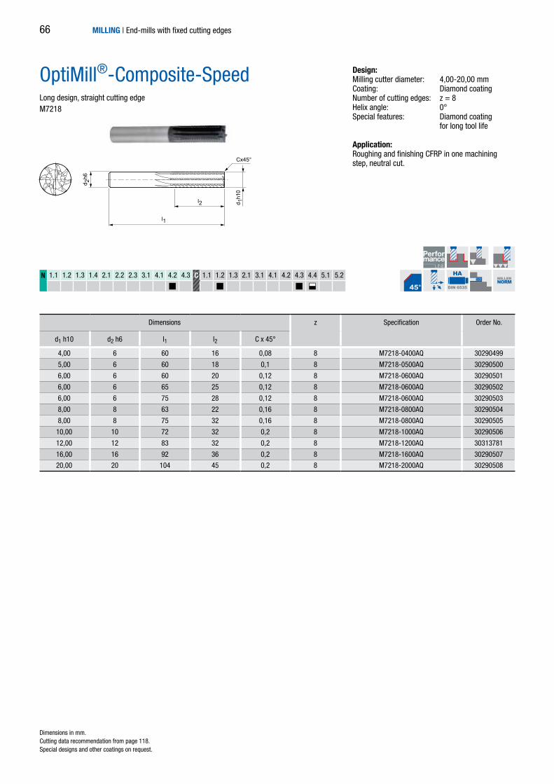
l2
l1
d 2h6
d 1h1
0
Cx45°
N 1.1 1.2 1.3 1.4 2.1 2.2 2.3 3.1 4.1 4.2 4.3 C 1.1 1.2 1.3 2.1 3.1 4.1 4.2 4.3 4.4 5.1 5.2
HA
DIN 6535
MILLERNORM
4,00 6 60 16 0,08 8 M7218-0400AQ 30290499
5,00 6 60 18 0,1 8 M7218-0500AQ 30290500
6,00 6 60 20 0,12 8 M7218-0600AQ 30290501
6,00 6 65 25 0,12 8 M7218-0600AQ 30290502
6,00 6 75 28 0,12 8 M7218-0600AQ 30290503
8,00 8 63 22 0,16 8 M7218-0800AQ 30290504
8,00 8 75 32 0,16 8 M7218-0800AQ 30290505
10,00 10 72 32 0,2 8 M7218-1000AQ 30290506
12,00 12 83 32 0,2 8 M7218-1200AQ 30313781
16,00 16 92 36 0,2 8 M7218-1600AQ 30290507
20,00 20 104 45 0,2 8 M7218-2000AQ 30290508
OptiMill®-Composite-SpeedLong design, straight cutting edge M7218
Dimensions z Specification Order No.
d1 h10 d2 h6 l1 l2 C x 45°
Dimensions in mm. Cutting data recommendation from page 118.Special designs and other coatings on request.
MILLING | End-mills with fixed cutting edges
Design:Milling cutter diameter: 4,00-20,00 mmCoating: Diamond coatingNumber of cutting edges: z = 8Helix angle: 0°Special features: Diamond coating for long tool life
Application: Roughing and finishing CFRP in one machiningstep, neutral cut.
66

l2
l1
d 2h6
d 1h1
0
Cx45°
N 1.1 1.2 1.3 1.4 2.1 2.2 2.3 3.1 4.1 4.2 4.3 C 1.1 1.2 1.3 2.1 3.1 4.1 4.2 4.3 4.4 5.1 5.2
HA
DIN 6535
MILLERNORM
4,00 6 60 16 0,08 8 M7228-0400AQ 30290509
5,00 6 60 18 0,1 8 M7228-0500AQ 30290510
6,00 6 60 20 0,12 8 M7228-0600AQ 30290511
6,00 6 65 25 0,12 8 M7228-0600AQ 30290512
6,00 6 75 28 0,12 8 M7228-0600AQ 30290513
8,00 8 63 22 0,16 8 M7228-0800AQ 30290514
8,00 8 75 32 0,16 8 M7228-0800AQ 30290515
10,00 10 72 32 0,2 8 M7228-1000AQ 30290516
12,00 12 83 32 0,2 8 M7228-1200AQ 30290517
16,00 16 92 36 0,2 8 M7228-1600AQ 30290518
20,00 20 104 45 0,2 8 M7228-2000AQ 30290519
OptiMill®-Composite-SpeedLong design, pulling cutting edge M7228
Dimensions z Specification Order No.
d1 h10 d2 h6 l1 l2 C x 45°
Dimensions in mm. Cutting data recommendation from page 118.Special designs and other coatings on request.
MILLING | End-mills with fixed cutting edges
Design:Milling cutter diameter: 4,00-20,00 mmCoating: Diamond coatingNumber of cutting edges: z = 8Helix angle: 8°Special features: Diamond coating for long tool life
Application: Pulling cutting edge for better removal of the chips/dust (e.g. on milling pockets and slots). Particularly suitable for difficult-to-machine surface layers (e.g. UD or copper mesh) to prevent delamination on the underside of the part.
67
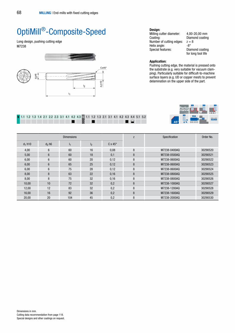
N 1.1 1.2 1.3 1.4 2.1 2.2 2.3 3.1 4.1 4.2 4.3 C 1.1 1.2 1.3 2.1 3.1 4.1 4.2 4.3 4.4 5.1 5.2
l2
l1
d 2h6
d 1h1
0
Cx45°
HA
DIN 6535
MILLERNORM
4,00 6 60 16 0,08 8 M7238-0400AQ 30290520
5,00 6 60 18 0,1 8 M7238-0500AQ 30290521
6,00 6 60 20 0,12 8 M7238-0600AQ 30290522
6,00 6 65 25 0,12 8 M7238-0600AQ 30290523
6,00 6 75 28 0,12 8 M7238-0600AQ 30290524
8,00 8 63 22 0,16 8 M7238-0800AQ 30290525
8,00 8 75 32 0,16 8 M7238-0800AQ 30290526
10,00 10 72 32 0,2 8 M7238-1000AQ 30290527
12,00 12 83 32 0,2 8 M7238-1200AQ 30290528
16,00 16 92 36 0,2 8 M7238-1600AQ 30290529
20,00 20 104 45 0,2 8 M7238-2000AQ 30290530
OptiMill®-Composite-SpeedLong design, pushing cutting edgeM7238
Dimensions z Specification Order No.
d1 h10 d2 h6 l1 l2 C x 45°
Dimensions in mm. Cutting data recommendation from page 118.Special designs and other coatings on request.
MILLING | End-mills with fixed cutting edges
Design:Milling cutter diameter: 4,00-20,00 mmCoating: Diamond coatingNumber of cutting edges: z = 8Helix angle: -8°Special features: Diamond coating for long tool life
Application: Pushing cutting edge, the material is pressed onto the substrate (e.g. very suitable for vacuum clam-ping). Particularly suitable for difficult-to-machine surface layers (e.g. UD or copper mesh) to preventdelamination on the upper side of the part.
68

1,00 3 38 5 Vielzahn M7901-0100AQ 30467717
2,00 3 38 9 Vielzahn M7901-0200AQ 30467719
3,00 3 38 9 Vielzahn M7901-0300AQ 30467721
l2
l1
d 2h6
d 1js1
0
N 1.1 1.2 1.3 1.4 2.1 2.2 2.3 3.1 4.1 4.2 4.3 C 1.1 1.2 1.3 2.1 3.1 4.1 4.2 4.3 4.4 5.1 5.2
HA
DIN 6535
MILLERNORM
MICRO-RouterShort design, pulling cutting edge M7901
Dimensions z Specification Order No.
d1 js10 d2 h6 l1 l2
Dimensions in mm. Cutting data recommendation from page 118.Special designs and other coatings on request.
MILLING | End-mills with fixed cutting edges
Design:Milling cutter diameter: 1,00-3,00 mmCoating: Diamond coatingNumber of cutting edges: MultipleSpecial features: Diamond coating for long tool life
Application:Pulling cutting edge for better removal of the chips/dust (e.g. on milling pockets and slots). Particularly suitable for difficult-to-machine surface layers (e.g. UD or copper mesh) to prevent delamination on the underside of the part.
Medium tooth
1,00 3 38 5 Multiple M7901-0100AQ 30467717
2,00 3 38 9 Multiple M7901-0200AQ 30467719
3,00 3 38 9 Multiple M7901-0300AQ 30467721
69

l1
l2 d 1 h
10
d 2 h
6
Cx45°
3,00 6 57 8 0,06 2 M7222-0300AQ 30355245
4,00 6 57 11 0,08 2 M7222-0400AQ 30355246
5,00 6 57 13 0,10 2 M7222-0500AQ 30355247
6,00 6 57 13 0,12 2 M7222-0600AQ 30355248
8,00 8 63 19 0,16 2 M7222-0800AQ 30355250
10,00 10 72 22 0,20 2 M7222-1000AQ 30340685
12,00 12 83 26 0,20 2 M7222-1200AQ 30355251
14,00 14 83 26 0,20 2 M7222-1400AQ 30355252
16,00 16 92 32 0,20 2 M7222-1600AQ 30355253
18,00 18 92 32 0,20 2 M7222-1800AQ 30355254
20,00 20 104 38 0,20 2 M7222-2000AQ 30355255
N 1.1 1.2 1.3 1.4 2.1 2.2 2.3 3.1 4.1 4.2 4.3 C 1.1 1.2 1.3 2.1 3.1 4.1 4.2 4.3 4.4 5.1 5.2
HA
DIN 6535
MILLERNORM
OptiMill®-Composite-DuoLong designM7222
Design:Milling cutter diameter: 3,00-20,00 mmCoating: Diamond coatingNumber of cutting edges: z = 2Helix angle: 15° Special features: Point geometry Diamond coating for long tool life
Application: For finishing CFRP/GFRP parts with high surface finish requirements.
Dimensions z Specification Order No.
d1 h10 d2 h6 l1 l2 C x 45°
Dimensions in mm. Cutting data recommendation from page 118.Special designs and other coatings on request.
MILLING | End-mills with fixed cutting edges70
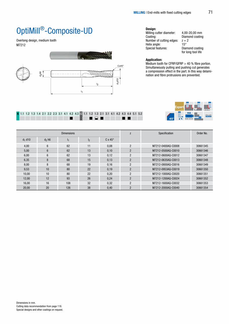
l2
l1
d 2h6
d 1d1
0
Cx45°
4,00 6 62 11 0,08 2 M7212-0400AQ-C0008 30661345
5,00 6 62 13 0,10 2 M7212-0500AQ-C0010 30661346
6,00 6 62 13 0,12 2 M7212-0600AQ-C0012 30661347
6,35 8 68 15 0,13 2 M7212-0635AQ-C0013 30661348
8,00 8 68 19 0,16 2 M7212-0800AQ-C0016 30661349
9,53 10 80 22 0,19 2 M7212-0953AQ-C0019 30661350
10,00 10 80 22 0,20 2 M7212-1000AQ-C0020 30661351
12,00 12 93 26 0,24 2 M7212-1200AQ-C0024 30661352
16,00 16 108 32 0,32 2 M7212-1600AQ-C0032 30661353
20,00 20 126 38 0,40 2 M7212-2000AQ-C0040 30661354
N 1.1 1.2 1.3 1.4 2.1 2.2 2.3 3.1 4.1 4.2 4.3 C 1.1 1.2 1.3 2.1 3.1 4.1 4.2 4.3 4.4 5.1 5.2
HA
DIN 6535
MILLERNORM
OptiMill®-Composite-UDOverlong design, medium tooth M7212
Dimensions z Specification Order No.
d1 d10 d2 h6 l1 l2 C x 45°
Dimensions in mm. Cutting data recommendation from page 118.Special designs and other coatings on request.
MILLING | End-mills with fixed cutting edges
Design:Milling cutter diameter: 4,00-20,00 mmCoating: Diamond coatingNumber of cutting edges: z = 2Helix angle: 15°Special features: Diamond coating for long tool life
Application: Medium tooth for CFRP/GFRP > 40 % fibre portion. Simultaneously pulling and pushing cut generates a compression effect in the part. In this way delami-nation and fibre protrusions are prevented.
71

l2
l1
d 2h6
d 1d1
0
Cx45°
6,00 6 62 13 0,12 2 M7242-0600AQ-C0012 30661284
6,35 8 68 15 0,13 2 M7242-0635AQ-C0013 30671633
8,00 8 68 19 0,16 2 M7242-0800AQ-C0016 30661288
9,53 10 80 22 0,19 2 M7242-0953AQ-C0019 30671634
10,00 10 80 22 0,20 2 M7242-1000AQ-C0020 30661290
12,00 12 93 26 0,24 2 M7242-1200AQ-C0024 30671635
16,00 16 108 32 0,32 2 M7242-1600AQ-C0032 30671636
20,00 20 126 38 0,40 2 M7242-2000AQ-C0040 30671637
N 1.1 1.2 1.3 1.4 2.1 2.2 2.3 3.1 4.1 4.2 4.3 C 1.1 1.2 1.3 2.1 3.1 4.1 4.2 4.3 4.4 5.1 5.2
HA
DIN 6535
MILLERNORM
OptiMill®-Composite-UDOverlong design, coarse tooth M7242
Dimensions z Specification Order No.
d1 d10 d2 h6 l1 l2 C x 45°
Dimensions in mm. Cutting data recommendation from page 118.Special designs and other coatings on request.
MILLING | End-mills with fixed cutting edges
Design:Milling cutter diameter: 6,00-20,00 mmCoating: Diamond coatingNumber of cutting edges: z = 2Helix angle: 15°Special features: Diamond coating for long tool life
Application: Coarse tooth for CFRP/GFRP < 40 % fibre portion. Simultaneously pulling and pushing cut generates a compression effect in the part. In this way delami-nation and fibre protrusions are prevented.
72

4,00 4 75 20 2 M7402-0400AU 30290531
5,00 5 75 25 2 M7402-0500AU 30290532
6,00 6 100 35 2 M7402-0600AU 30290533
8,00 8 100 40 2 M7402-0800AU 30290534
10,00 10 125 50 2 M7402-1000AU 30290535
12,00 12 125 60 2 M7402-1200AU 30290536
16,00 16 150 75 2 M7402-1600AU 30290537
20,00 20 104 45 2 M7402-2000AU 30290538
l2
l1
d 2h6
d 1h1
0N 1.1 1.2 1.3 1.4 2.1 2.2 2.3 3.1 4.1 4.2 4.3 C 1.1 1.2 1.3 2.1 3.1 4.1 4.2 4.3 4.4 5.1 5.2
HA
DIN 6535
MILLERNORM
OptiMill®-Composite-TwinCutExtra long designM7402
Dimensions z Specification Order No.
d1 h10 d2 h6 l1 l2
Dimensions in mm. Cutting data recommendation from page 118.Special designs and other coatings on request.
MILLING | End-mills with fixed cutting edges
Design:Milling cutter diameter: 4,00-20,00 mmCoating: UncoatedNumber of cutting edges: z = 2Helix angle: 0°
Application: For milling aramide fibre-reinforced plastics in the roughing area. The alternate arrangement of the cutting edges prevents delamination with plaited fibres and with textile fibre structures.
73
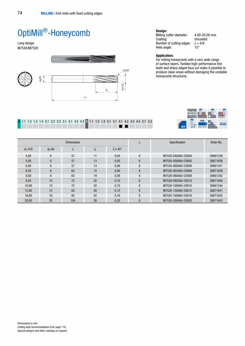
4,00 6 57 11 0,04 6 M7526-0400AU-C0004 30661239
5,00 6 57 13 0,05 6 M7526-0500AU-C0005 30671638
6,00 6 57 13 0,06 8 M7528-0600AU-C0006 30661241
6,35 8 63 15 0,06 8 M7528-0635AU-C0006 30671639
8,00 8 63 19 0,08 8 M7528-0800AU-C0008 30661242
9,53 10 72 22 0,10 8 M7528-0953AU-C0010 30671640
10,00 10 72 22 0,10 8 M7528-1000AU-C0010 30661244
12,00 12 83 26 0,12 8 M7528-1200AU-C0012 30671641
16,00 16 92 32 0,16 8 M7528-1600AU-C0016 30671642
20,00 20 104 38 0,20 8 M7528-2000AU-C0020 30671643
l2
l1
d 2h6
d 1h1
0
Cx45°
N 1.1 1.2 1.3 1.4 2.1 2.2 2.3 3.1 4.1 4.2 4.3 C 1.1 1.2 1.3 2.1 3.1 4.1 4.2 4.3 4.4 5.1 5.2
HA
DIN 6535
MILLERNORM
OptiMill®-HoneycombLong design M7526/M7528
Dimensions z Specification Order No.
d1 h10 d2 h6 l1 l2 C x 45°
Dimensions in mm. Cutting data recommendation from page 118.Special designs and other coatings on request.
MILLING | End-mills with fixed cutting edges
Design:Milling cutter diameter: 4,00-20,00 mmCoating: UncoatedNumber of cutting edges: z = 6/8Helix angle: 15°
Application: For milling honeycomb with a very wide range of surface layers. Twisted high-performance fine teeth and sharp-edged face cut make it possible to produce clean areas without damaging the unstable honeycomb structures.
74

MILLING | End-mills with fixed cutting edges 75

MILLING | End-mills with fixed cutting edges76

Universal use
OptiMill-Uni-Rough & Finish 78
OptiMill-Uni-HPC-Rough 79
MILLING | End-mills with fixed cutting edges
SHOULDER MILLING – ROUGHING
77

6,00 6 57 13 – 3 M3060-0600BI 30126317
8,00 8 63 19 0,08 3 M3060-0800BI 30126318
10,00 10 72 22 0,10 4 M3060-1000BI 30089974
12,00 12 83 26 0,12 4 M3060-1200BI 30126320
14,00 14 83 26 0,14 4 M3060-1400BI 30126352
16,00 16 92 32 0,16 4 M3060-1600BI 30061834
18,00 18 92 32 0,18 4 M3060-1800BI 30126353
20,00 20 104 38 0,20 4 M3060-2000BI 30126354
P 1 2 3 4 5 6 M 1 2 3 K 1 2 3 N 1 2 3 4 S 1 2 3 4 5 H 1 2
d 2 h
6
l2
l1
d 1 h
10
Cx45°
z = 3 z = 4
HB
DIN 6535 DIN6527
OptiMill®-Uni-Rough & FinishLong designM3060
Design:Milling cutter diameter: 6,00-20,00 mmCoating: MF5Number of cutting edges: z = 3 up to ø 8 mm z = 4 from ø 10 mm Helix angle: 30°
Dimensions z Specification Order No.
d1 h10 d2 h6 l1 l2 C x 45°
Dimensions in mm. Cutting data recommendation from page 118.Special designs and other coatings on request.
MILLING | End-mills with fixed cutting edges78

*5,00 6 54 8 – 0,30 3 M3081-0500BY 30427454
6,00 6 54 8 18 0,30 3 M3081-0600BY 30427457
*7,00 8 58 11 – 0,30 3 M3081-0700BY 30427458
8,00 8 58 11 22 0,30 3 M3081-0800BY 30427460
*9,00 10 66 13 – 0,50 4 M3081-0900BY 30427461
10,00 10 66 13 26 0,50 4 M3081-1000BY 30427462
12,00 12 73 16 28 0,50 4 M3081-1200BY 30427464
14,00 14 76 16 31 0,50 4 M3081-1400BY 30427465
16,00 16 82 19 34 0,50 4 M3081-1600BY 30427466
18,00 18 84 19 36 0,50 4 M3081-1800BY 30427467
20,00 20 92 20 42 0,50 4 M3081-2000BY 30427468
P 1 2 3 4 5 6 M 1 2 3 K 1 2 3 N 1 2 3 4 S 1 2 3 4 5 H 1 2
d 2 h
6
l2
l3
d 1 d
11
l1
Cx45°
z = 4z = 3
HB
DIN 6535 DIN6527
OptiMill®-Uni-HPC-RoughShort design with neckM3081
Dimensions z Specification Order No.
d1 d11 d2 h6 l1 l2 l3 C x 45°
Dimensions in mm. * Design without neck.Cutting data recommendation from page 118.Special designs and other coatings on request.
MILLING | End-mills with fixed cutting edges
Design:Milling cutter diameter: 5,00-20,00 mmCoating: MF3Number of cutting edges: z = 3 up to ø 8 mm z = 4 from ø 9 mm Helix angle: 30° Special features: Unequal spacing, profile undercut HPC roughing teeth
79

*4,00 6 57 8 – 0,30 3 M3181-0400BY 30427427
*5,00 6 57 13 – 0,30 3 M3181-0500BY 30427428
6,00 6 57 13 21 0,30 3 M3181-0600BY 30427430
*7,00 8 63 16 – 0,30 3 M3181-0700BY 30427432
8,00 8 63 16 26 0,30 3 M3181-0800BY 30427433
*9,00 10 72 19 – 0,50 4 M3181-0900BY 30427434
10,00 10 72 22 32 0,50 4 M3181-1000BY 30427437
*11,00 12 83 26 – 0,50 4 M3181-1100BY 30427438
12,00 12 83 26 38 0,50 4 M3181-1200BY 30427439
*13,00 14 83 26 – 0,50 4 M3181-1300BY 30427440
14,00 14 83 26 42 0,50 4 M3181-1400BY 30427441
16,00 16 92 32 44 0,50 4 M3181-1600BY 30427443
18,00 18 92 32 48 0,50 4 M3181-1800BY 30427444
20,00 20 104 38 54 0,50 4 M3181-2000BY 30427447
25,00 25 121 45 65 0,50 5 M3181-2500BY 30427448
P 1 2 3 4 5 6 M 1 2 3 K 1 2 3 N 1 2 3 4 S 1 2 3 4 5 H 1 2
d 2 h
6
l2
l3
d 1 d
11
l1
Cx45°
z = 3 z = 4 z = 5
HB
DIN 6535 DIN6527
OptiMill®-Uni-HPC-RoughLong design with neckM3181
Dimensions z Specification Order No.
d1 d11 d2 h6 l1 l2 l3 C x 45°
Dimensions in mm. * Design without neck.Cutting data recommendation from page 118.Special designs and other coatings on request.
MILLING | End-mills with fixed cutting edges
Design:Milling cutter diameter: 4,00-25,00 mmCoating: MF3Number of cutting edges: z = 3 up to ø 8 mm z = 4 from ø 9 mm z = 5 from ø 25 mm Helix angle: 30° Special features: Unequal spacing, profile undercut HPC roughing teeth
80

MILLING | End-mills with fixed cutting edges 81

MILLING | End-mills with fixed cutting edges82

Universal use
OptiMill-Uni-Finish 84
OptiMill-Uni-HPC-Finish 86
Hardened steel
OptiMill-Hardened 87
MILLING | End-mills with fixed cutting edges
SHOULDER MILLING – FINISHING
83

d 2 h
6
l2
l1
d 1 h
10
Cx45°
z = 8z = 6
4,00 6 57 11 0,04 6 M3046-0400AZ 30259561 M3046-0400BZ 30247182
5,00 6 57 13 0,05 6 M3046-0500AZ 30259563 M3046-0500BZ 30247184
6,00 6 57 13 0,06 6 M3046-0600AZ 30259565 M3046-0600BZ 30247186
8,00 8 63 19 0,08 6 M3046-0800AZ 30259567 M3046-0800BZ 30247188
10,00 10 72 22 0,10 6 M3046-1000AZ 30259569 M3046-1000BZ 30247190
12,00 12 83 26 0,12 6 M3046-1200AZ 30259571 M3046-1200BZ 30247192
16,00 16 92 32 0,16 6 M3046-1600AZ 30259573 M3046-1600BZ 30247194
20,00 20 104 38 0,20 8 M3048-2000AZ 30259575 M3048-2000BZ 30247196
25,00 25 150 75 0,25 8 M3048-2500AZ 30259577 M3048-2500BZ 30247373
32,00 32 150 75 0,32 8 M3048-3200AZ 30259579 M3048-3200BZ 30247384
P 1 2 3 4 5 6 M 1 2 3 K 1 2 3 N 1 2 3 4 S 1 2 3 4 5 H 1 2
HA
DIN 6535
HB
DIN 6535 DIN6527
OptiMill®-Uni-FinishLong designM3046/M3048
Design:Milling cutter diameter: 4,00-32,00 mmCoating: MF4Number of cutting edges: z = 6 up to ø 16 mm
z = 8 from ø 20 mmHelix angle: 45°
Dimensions z Shank form HA Shank form HB
d1 h10 d2 h6 l1 l2 C x 45° Specification Order No. Specification Order No.
Dimensions in mm. Cutting data recommendation from page 118.Special designs and other coatings on request.
MILLING | End-mills with fixed cutting edges84

4,00 6 62 16 0,04 6 M3049-0400AZ 30259562 M3049-0400BZ 30247183
5,00 6 62 18 0,05 6 M3049-0500AZ 30259564 M3049-0500BZ 30247185
6,00 6 62 18 0,06 6 M3049-0600AZ 30259566 M3049-0600BZ 30247187
8,00 8 68 24 0,08 6 M3049-0800AZ 30259568 M3049-0800BZ 30247189
10,00 10 80 30 0,10 6 M3049-1000AZ 30259570 M3049-1000BZ 30247191
12,00 12 93 36 0,12 6 M3049-1200AZ 30259572 M3049-1200BZ 30247193
16,00 16 108 48 0,16 6 M3049-1600AZ 30259574 M3049-1600BZ 30247195
20,00 20 126 60 0,20 8 M3049-2000AZ 30259576 M3049-2000BZ 30247197
20,00 20 135 75 0,20 8 M3049-2000AZ 30259582 M3049-2000BZ 30254401
20,00 20 150 95 0,20 8 M3049-2000AZ 30259583 M3049-2000BZ 30254402
25,00 25 160 95 0,25 8 M3049-2500AZ 30259578 M3049-2500BZ 30247376
32,00 32 160 95 0,32 8 M3049-3200AZ 30259581 M3049-3200BZ 30247386
P 1 2 3 4 5 6 M 1 2 3 K 1 2 3 N 1 2 3 4 S 1 2 3 4 5 H 1 2
d 2 h
6
l2
l1
d 1 h
10
Cx45°
z = 6 z = 8
HA
DIN 6535
HB
DIN 6535 DIN6527
Dimensions z Shank form HA Shank form HB
d1 h10 d2 h6 l1 l2 C x 45° Specification Order No. Specification Order No.
OptiMill®-Uni-FinishOverlong designM3049
Design:Milling cutter diameter: 4,00-32,00 mmCoating: MF4Number of cutting edges: z = 6 up to ø 16 mm
z = 8 from ø 20 mmHelix angle: 45°
Dimensions in mm. Cutting data recommendation from page 118.Special designs and other coatings on request.
MILLING | End-mills with fixed cutting edges 85
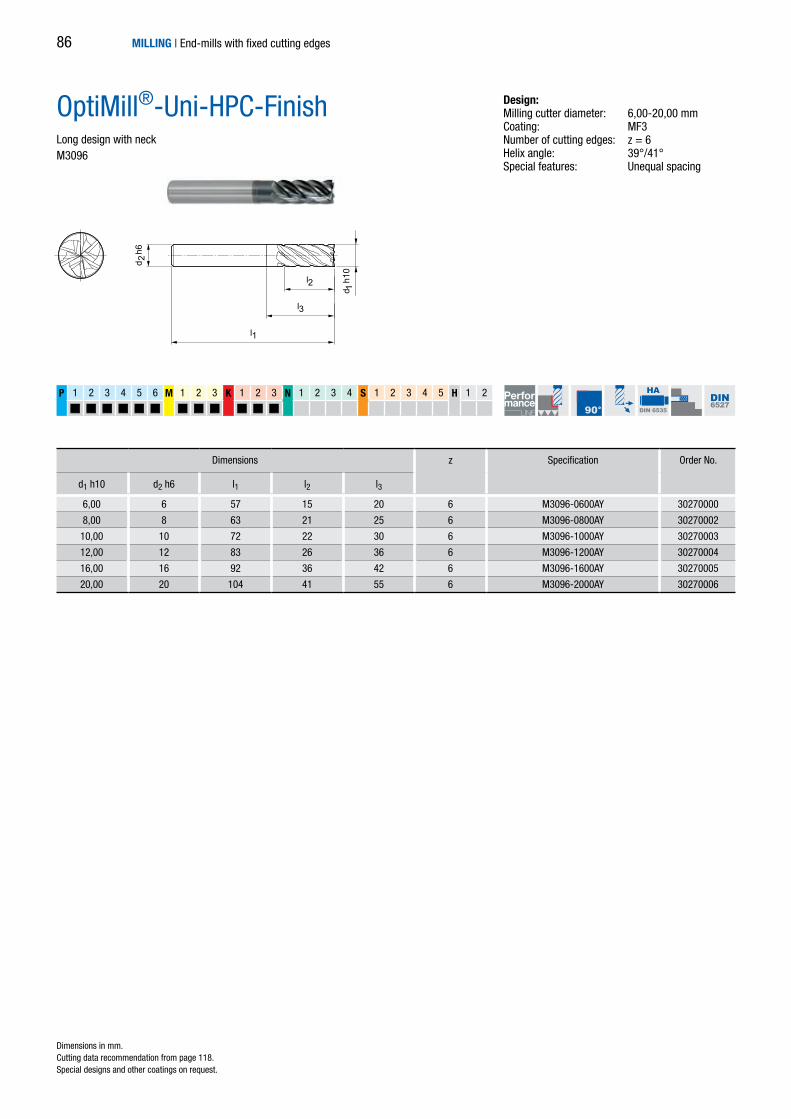
d 2 h
6
l2
l3
d 1 h
10l1
6,00 6 57 15 20 6 M3096-0600AY 30270000
8,00 8 63 21 25 6 M3096-0800AY 30270002
10,00 10 72 22 30 6 M3096-1000AY 30270003
12,00 12 83 26 36 6 M3096-1200AY 30270004
16,00 16 92 36 42 6 M3096-1600AY 30270005
20,00 20 104 41 55 6 M3096-2000AY 30270006
P 1 2 3 4 5 6 M 1 2 3 K 1 2 3 N 1 2 3 4 S 1 2 3 4 5 H 1 2
HA
DIN 6535 DIN6527
OptiMill®-Uni-HPC-FinishLong design with neckM3096
Design:Milling cutter diameter: 6,00-20,00 mmCoating: MF3Number of cutting edges: z = 6Helix angle: 39°/41°Special features: Unequal spacing
Dimensions z Specification Order No.
d1 h10 d2 h6 l1 l2 l3
Dimensions in mm. Cutting data recommendation from page 118.Special designs and other coatings on request.
MILLING | End-mills with fixed cutting edges86

4,00 6 57 11 6 M3076-0400AZ 30247198
5,00 6 57 13 6 M3076-0500AZ 30247199
6,00 6 57 13 6 M3076-0600AZ 30247200
8,00 8 63 19 6 M3076-0800AZ 30247202
10,00 10 72 22 6 M3076-1000AZ 30247204
12,00 12 83 26 6 M3076-1200AZ 30247206
14,00 14 83 26 6 M3076-1400AZ 30247208
16,00 16 92 32 8 M3078-1600AZ 30247210
18,00 18 92 32 8 M3078-1800AZ 30247212
20,00 20 104 38 8 M3078-2000AZ 30247214
P 1 2 3 4 5 6 M 1 2 3 K 1 2 3 N 1 2 3 4 S 1 2 3 4 5 H 1 2
d 2 h
6
l2
l1
d 1 h
10
z = 8z = 6
HA
DIN 6535
MILLERNORM
OptiMill®-HardenedLong designM3076/M3078
Design:Milling cutter diameter: 4,00-20,00 mmCoating: MF4Number of cutting edges: z = 6 up to ø 14 mm z = 8 from ø 16 mmHelix angle: 50°
Dimensions z Specification Order No.
d1 h10 d2 h6 l1 l2
Dimensions in mm. Cutting data recommendation from page 118.Special designs and other coatings on request.
MILLING | End-mills with fixed cutting edges 87

6,00 6 62 18 6 M3071-0600AZ 30247201
8,00 8 68 24 6 M3071-0800AZ 30247203
10,00 10 80 30 6 M3071-1000AZ 30247205
12,00 12 93 36 6 M3071-1200AZ 30247207
14,00 14 99 42 6 M3071-1400AZ 30247209
16,00 16 108 48 8 M3071-1600AZ 30247211
18,00 18 114 54 8 M3071-1800AZ 30247213
20,00 20 126 60 8 M3071-2000AZ 30247215
P 1 2 3 4 5 6 M 1 2 3 K 1 2 3 N 1 2 3 4 S 1 2 3 4 5 H 1 2
z = 8z = 6
d 2 h
6
l2
l1
d 1 h
10
HA
DIN 6535
MILLERNORM
OptiMill®-HardenedOverlong designM3071
Design:Milling cutter diameter: 6,00-20,00 mmCoating: MF4Number of cutting edges: z = 6 up to ø 14 mm
z = 8 from ø 16 mmHelix angle: 50°
Dimensions z Specification Order No.
d1 h10 d2 h6 l1 l2
Dimensions in mm. Cutting data recommendation from page 118.Special designs and other coatings on request.
MILLING | End-mills with fixed cutting edges88

MILLING | End-mills with fixed cutting edges 89
MILLING | End-mills with fixed cutting edges90

Universal use
OptiMill-Tro-Uni 92
Steel and stainless steel
OptiMill-Tro-PM 93
Titanium and nickel-based alloys
OptiMill-Tro-S 94
OptiMill-Tro-Titan 95
Hardened steel
OptiMill-Tro-H 96
TROCHOIDAL MILLING
MILLING | End-mills with fixed cutting edges 91

4,00 6 62 16 23 0,08 5 M3099-0400BY-C0008 30547814
5,00 6 62 17 24 0,10 5 M3099-0500BY-C0010 30547815
6,00 6 62 18 25 0,12 5 M3099-0600BY-C0012 30547816
8,00 8 68 24 30 0,16 5 M3099-0800BY-C0016 30547818
10,00 10 80 30 35 0,20 5 M3099-1000BY-C0020 30547819
12,00 12 93 36 45 0,24 5 M3099-1200BY-C0024 30547820
14,00 14 99 42 50 0,28 5 M3099-1400BY-C0028 30547821
16,00 16 108 48 55 0,32 5 M3099-1600BY-C0032 30547822
18,00 18 117 54 67 0,36 5 M3099-1800BY-C0036 30547823
20,00 20 126 60 70 0,40 5 M3099-2000BY-C0040 30547825
25,00 25 150 75 92 0,50 5 M3099-2500BY-C0050 30547834
P 1 2 3 4 5 6 M 1 2 3 K 1 2 3 N 1 2 3 4 S 1 2 3 4 5 H 1 2
HB
DIN 6535
MILLERNORM
d 2 h
6
l1
l2
l3
d 1 f8
Cx45°
Dimensions z Specification Order No.
d1 f8 d2 h6 l1 l2 l3 C x 45°
OptiMill®-Tro-Uni3xD design with neckM3099
Design:Milling cutter diameter: 4,00-25,00 mmCoating: MF3Number of cutting edges: z = 5Helix angle: 41°-42°Balancing quality: Cutting edge portion balanced to G2.5 in acc. with DIN ISO 1940-G2.5 Special features: Unequal spacing
Application:Especially for trochoidal milling – part-contactcutting/trimming. For cutting depths up to 3xDwith special chip breaker for optimum chipcontrol.
Dimensions in mm. Cutting data recommendation from page 118.Special designs and other coatings on request.
MILLING | End-mills with fixed cutting edges92

d 2 h
6
l1
l2
l3
d 1 f8
Cx45°
4,00 6 62 16 23 0,08 5 M3299-0400BL-C0008 30543767
5,00 6 62 17 24 0,10 5 M3299-0500BL-C0010 30543765
6,00 6 62 18 25 0,12 5 M3299-0600BL-C0012 30524804
8,00 8 68 24 30 0,16 5 M3299-0800BL-C0016 30524805
10,00 10 80 30 35 0,20 5 M3299-1000BL-C0020 30524806
12,00 12 93 36 45 0,24 5 M3299-1200BL-C0024 30524807
14,00 14 99 42 50 0,28 5 M3299-1400BL-C0028 30524808
16,00 16 108 48 55 0,32 5 M3299-1600BL-C0032 30524809
18,00 18 117 54 67 0,36 5 M3299-1800BL-C0036 30566345
20,00 20 126 60 70 0,40 5 M3299-2000BL-C0040 30524810
25,00 25 150 75 92 0,50 5 M3299-2500BL-C0050 30566346
P 1 2 3 4 5 6 M 1 2 3 K 1 2 3 N 1 2 3 4 S 1 2 3 4 5 H 1 2
HB
DIN 6535
MILLERNORM
Dimensions z Specification Order No.
d1 f8 d2 h6 l1 l2 l3 C x 45°
OptiMill®-Tro-PM3xD design with neck M3299
Design:Milling cutter diameter: 4,00-25,00 mmCoating: MF2Number of cutting edges: z = 5Helix angle: 41°-42°Balancing quality: Cutting edge portion balanced to G2.5 in acc. with DIN ISO 1940-G2.5Special features: Unequal spacing
Application: Especially for trochoidal milling – part-contactcutting/trimming. For cutting depths up to 3xDwith special chip breaker for optimum chipcontrol.
Dimensions in mm. Cutting data recommendation from page 118.Special designs and other coatings on request.
MILLING | End-mills with fixed cutting edges 93

P 1 2 3 4 5 6 M 1 2 3 K 1 2 3 N 1 2 3 4 S 1 2 3 4 5 H 1 2
5,00 6 62 17 24 0,10 5 M3699-0500BI-R0010 30543756
6,00 6 62 18 25 0,10 5 M3699-0600BI-R0010 30524811
8,00 8 68 24 30 0,20 5 M3699-0800BI-R0020 30524812
10,00 10 80 30 35 0,20 5 M3699-1000BI-R0020 30524813
12,00 12 93 36 45 0,30 5 M3699-1200BI-R0030 30524814
14,00 14 99 42 50 0,30 5 M3699-1400BI-R0030 30524815
16,00 16 108 48 55 0,30 5 M3699-1600BI-R0030 30524816
18,00 18 117 54 67 0,30 5 M3699-1800BI-R0030 30566343
20,00 20 126 60 70 0,30 5 M3699-2000BI-R0030 30524817
25,00 25 150 75 92 0,40 5 M3699-2500BI-R0040 30566344
d 2 h
6
l1
l2
l3
d 1 f8
R
HB
DIN 6535
MILLERNORM
Dimensions z Specification Order No.
d1 f8 d2 h6 l1 l2 l3 R
OptiMill®-Tro-S3xD design with neck M3699
Design:Milling cutter diameter: 5,00-25,00 mmCoating: MF5Number of cutting edges: z = 5Helix angle: 41°-42° Balancing quality: Cutting edge portion balanced to G2.5 in acc. with DIN ISO 1940-G2.5 Special features: Unequal spacing
Application:Especially for trochoidal milling – part-contactcutting/trimming. For cutting depths up to 3xD.
Dimensions in mm. Cutting data recommendation from page 118.Special designs and other coatings on request.
MILLING | End-mills with fixed cutting edges94

P 1 2 3 4 5 6 M 1 2 3 K 1 2 3 N 1 2 3 4 S 1 2 3 4 5 H 1 2
5,00 6 62 17 24 0,10 5 M3799-0500BJ-R0010 30651018
6,00 6 62 18 25 0,10 5 M3799-0600BJ-R0010 30651019
8,00 8 68 24 30 0,20 5 M3799-0800BJ-R0020 30651020
10,00 10 80 30 35 0,20 5 M3799-1000BJ-R0020 30651021
12,00 12 93 36 45 0,30 5 M3799-1200BJ-R0030 30651022
14,00 14 99 42 50 0,30 5 M3799-1400BJ-R0030 30651023
16,00 16 108 48 55 0,30 5 M3799-1600BJ-R0030 30651024
18,00 18 117 54 67 0,30 5 M3799-1800BJ-R0030 30651025
20,00 20 126 60 70 0,30 5 M3799-2000BJ-R0030 30651026
25,00 25 150 75 92 0,40 5 M3799-2500BJ-R0040 30651027
HB
DIN 6535
MILLERNORM
d 2 h
6
l1
l2
l3
d 1 f8
R
OptiMill®-Tro-Titan3xD design with neck M3799
Design:Milling cutter diameter: 5,00-25,00 mmCoating: MxBNumber of cutting edges: z = 5Helix angle: 41°-42°Balancing quality: Cutting edge portion balanced to G2.5 in acc. with DIN ISO 1940-G2.5 Special features: Unequal spacing
Application:Especially for trochoidal milling – part-contactcutting/trimming. For cutting depths up to 3xD.
Dimensions z Specification Order No.
d1 f8 d2 h6 l1 l2 l3 R
Dimensions in mm. Cutting data recommendation from page 118.Special designs and other coatings on request.
MILLING | End-mills with fixed cutting edges 95

P 1 2 3 4 5 6 M 1 2 3 K 1 2 3 N 1 2 3 4 S 1 2 3 4 5 H 1 2
5,00 6 62 17 24 0,10 5 M3079-0500BS-R0010 30580124
6,00 6 62 18 25 0,10 5 M3079-0600BS-R0010 30580125
8,00 8 68 24 30 0,20 5 M3079-0800BS-R0020 30580127
10,00 10 80 30 35 0,20 5 M3079-1000BS-R0020 30580128
12,00 12 93 36 45 0,30 5 M3079-1200BS-R0030 30580129
14,00 14 99 42 50 0,30 5 M3079-1400BS-R0030 30580130
16,00 16 108 48 55 0,30 5 M3079-1600BS-R0030 30580132
18,00 18 117 54 67 0,30 5 M3079-1800BS-R0030 30580133
20,00 20 126 60 70 0,30 5 M3079-2000BS-R0030 30580135
25,00 25 150 75 92 0,40 5 M3079-2500BS-R0040 30580136
d 2 h
6
l1
l2
l3
R
d 1 f8
HB
DIN 6535
MILLERNORM
OptiMill®-Tro-H3xD design with neck M3079
Design:Milling cutter diameter: 5,00-25,00 mmCoating: MxSNumber of cutting edges: z = 5Helix angle: 41°-42°Balancing quality: Cutting edge portion balanced to G2.5 in acc. with DIN ISO 1940-G2.5Special features: Unequal spacing
Application:Especially for trochoidal milling – part-contactcutting/trimming. For cutting depths up to 3xD.
Dimensions z Specification Order No.
d1 f8 d2 h6 l1 l2 l3 R
Dimensions in mm. Cutting data recommendation from page 118.Special designs and other coatings on request.
MILLING | End-mills with fixed cutting edges96

MILLING | End-mills with fixed cutting edges 97

MILLING | End-mills with fixed cutting edges98

MILLING | End-mills with fixed cutting edges
PROFILE MILLINGCUTTERSUniversal use
OptiMill-Uni-Radius 100
Hardened steel
OptiMill-Hardened-Radius 101
Fibre-reinforced plastic
OptiMill-Composite-MT-Radius 102
99

2,00 6 54 5 1,00 2 M3832-0200BZ 30247110
3,00 6 54 5 1,50 2 M3832-0300BZ 30247111
4,00 6 54 8 2,00 2 M3832-0400BZ 30247112
5,00 6 54 9 2,50 2 M3832-0500BZ 30247113
6,00 6 54 10 3,00 2 M3832-0600BZ 30247114
8,00 8 58 12 4,00 2 M3832-0800BZ 30247115
10,00 10 66 14 5,00 2 M3832-1000BZ 30247116
12,00 12 73 16 6,00 2 M3832-1200BZ 30247117
16,00 16 82 22 8,00 2 M3832-1600BZ 30247118
20,00 20 92 26 10,00 2 M3832-2000BZ 30247119
P 1 2 3 4 5 6 M 1 2 3 K 1 2 3 N 1 2 3 4 S 1 2 3 4 5 H 1 2
d 2 h
6
l2
l1
d 1 h
10
R
HB
DIN 6535 DIN6527
OptiMill®-Uni-RadiusShort designM3832
Design:Milling cutter diameter: 2,00-20,00 mmCoating: MF4Number of cutting edges: z = 2Helix angle: 30°
Dimensions z Specification Order No.
d1 h10 d2 h6 l1 l2 R
Dimensions in mm. Cutting data recommendation from page 118.Special designs and other coatings on request.
MILLING | End-mills with fixed cutting edges100

1,00 4 50 1,5 0,50 2 M3872-0100AZ 30259548
1,50 4 50 2,5 0,75 2 M3872-0150AZ 30259549
2,00 6 50 3 1,00 2 M3872-0200AZ 30259550
2,50 6 50 4 1,25 2 M3872-0250AZ 30259551
3,00 6 70 5 1,50 2 M3872-0300AZ 30259552
4,00 6 70 6 2,00 2 M3872-0400AZ 30259553
5,00 6 80 8 2,50 2 M3872-0500AZ 30259554
6,00 6 90 9 3,00 2 M3872-0600AZ 30259555
8,00 8 100 12 4,00 2 M3872-0800AZ 30259556
10,00 10 100 15 5,00 2 M3872-1000AZ 30259557
12,00 12 110 18 6,00 2 M3872-1200AZ 30259558
16,00 16 140 25 8,00 2 M3872-1600AZ 30259559
20,00 20 160 30 10,00 2 M3872-2000AZ 30259560
P 1 2 3 4 5 6 M 1 2 3 K 1 2 3 N 1 2 3 4 S 1 2 3 4 5 H 1 2
d 2 h
6
l2
l1
d 1 h
10
R
HA
DIN 6535
MILLERNORM
Dimensions z Specification Order No.
d1 h10 d2 h6 l1 l2 R
OptiMill®-Hardened-RadiusExtra long design M3872
Design:Milling cutter diameter: 1,00-20,00 mmCoating: MF4Number of cutting edges: z = 2Helix angle: 30°
Dimensions in mm. Cutting data recommendation from page 118.Special designs and other coatings on request.
MILLING | End-mills with fixed cutting edges 101

N 1.1 1.2 1.3 1.4 2.1 2.2 2.3 3.1 4.1 4.2 4.3 C 1.1 1.2 1.3 2.1 3.1 4.1 4.2 4.3 4.4 5.1 5.2
d 1h1
0
l2
l1
d 2h6
HA
DIN 6535
MILLERNORM
R
OptiMill®-Composite-MT-RadiusLong / overlong design, pulling cutting edge M7801
Dimensions in mm. Cutting data recommendation from page 118.Special designs and other coatings on request.
4,00 4 50 19 2,00 Multiple M7801-0400AU 30355129
5,00 5 50 19 2,50 Multiple M7801-0500AU 30355131
5,00 5 75 19 2,50 Multiple M7801-0500AU 30355132
6,00 6 60 22 3,00 Multiple M7801-0600AU 30355133
6,00 6 75 33 3,00 Multiple M7801-0600AU 30355134
8,00 8 63 29 4,00 Multiple M7801-0800AU 30355135
8,00 8 75 39 4,00 Multiple M7801-0800AU 30355136
10,00 10 72 30 5,00 Multiple M7801-1000AU 30342831
12,00 12 83 38 6,00 Multiple M7801-1200AU 30355137
16,00 16 92 44 8,00 Multiple M7801-1600AU 30355138
20,00 20 104 55 10,00 Multiple M7801-2000AU 30355139
Dimensions z Specification Order No.
d1 h10 d2 h6 l1 l2 R
MILLING | End-mills with fixed cutting edges
Design:Milling cutter diameter: 4,00-20,00 mmCoating: UncoatedNumber of cutting edges: Multiple
Application: Pulling cutting edge for better removal of thechips/dust (e.g. on milling pockets and slots).Particularly suitable for difficult-to-machinesurface layers (e.g. UD or copper mesh) toprevent delamination on the underside of the part.
Medium tooth
102

MILLING | End-mills with fixed cutting edges 103

MILLING | End-mills with fixed cutting edges104

Universal use
OptiMill-Chamfer 106
OptiMill-DrillMill 107
MILLING | End-mills with fixed cutting edges
CHAMFERING, DRILL AND DEBURRINGMILLING CUTTERS
105

4,00 4 54 9 4 M5390-0400AZ 30247388
6,00 6 54 12 4 M5390-0600AZ 30241828
8,00 8 58 15 4 M5390-0800AZ 30241829
10,00 10 66 16 4 M5390-1000AZ 30241830
12,00 12 73 18 4 M5390-1200AZ 30241831
16,00 16 82 25 4 M5390-1600AZ 30269759
20,00 20 92 30 4 M5390-2000AZ 30269760
P 1 2 3 4 5 6 M 1 2 3 K 1 2 3 N 1 2 3 4 S 1 2 3 4 5 H 1 2
d 2 h
6
d 1 h
7
90°
l1
l2
HA
DIN 6535
MILLERNORM
MILLING | End-mills with fixed cutting edges
OptiMill®-ChamferShort designM5390
Design:Milling cutter diameter: 4,00-20,00 mmCoating: MF4Number of cutting edges: z = 4Point angle: 90°Helix angle: 0°
Dimensions z Specification Order No.
d1 h7 d2 h6 l1 l2
Dimensions in mm. Cutting data recommendation from page 118.Special designs and other coatings on request.
106

3,00 6 57 8 2 M5490-0300AU 30247237
4,00 6 57 11 2 M5490-0400AU 30247238
5,00 6 57 13 2 M5490-0500AU 30247239
6,00 6 57 13 2 M5490-0600AU 30247240
8,00 8 63 19 2 M5490-0800AU 30247241
10,00 10 72 22 2 M5490-1000AU 30247242
12,00 12 83 26 2 M5490-1200AU 30247243
16,00 16 92 32 2 M5490-1600AU 30269758
P 1 2 3 4 5 6 M 1 2 3 K 1 2 3 N 1 2 3 4 S 1 2 3 4 5 H 1 2
d 2 h
6
d 1 h
10
90°
l1
l2
HA
DIN 6535 DIN6527
OptiMill®-DrillMillLong design with drill pointM5490
Dimensions z Specification Order No.
d1 h10 d2 h6 l1 l2
Dimensions in mm. Cutting data recommendation from page 118.Special designs and other coatings on request.
MILLING | End-mills with fixed cutting edges
Design:Milling cutter diameter: 3,00-16,00 mmCoating: Uncoated Number of cutting edges: z = 2Point angle: 90°Helix angle: 30°
Application: Drill milling cutter for milling, chamferingand drilling.
107

4
3
2
1
MILLING | End-mills with fixed cutting edges
CUSTOM SOLUTIONSEnd-mills with fixed cutting edges
Along with a comprehensive standard programme of end-mills with fixed cutting edges, MILLER also offers custom milling cutters, which are spe-cially tailored to the related machining tasks. Complex geometries and contours can be realised for high-precision, flexible manufacturing options. Even unusual tool concepts for the combination of machining steps or com-bination machining processes can be created at short notice – from the complex form cutter to the solid carbide disc milling cutter.
108

5
8
7
6
MILLING | End-mills with fixed cutting edges
1 PCD circular milling cutter, two cutting edges, for recesses in aluminium parts.2 Solid carbide end-mill, five cutting edges, special coating and radial coolant outlets in the chip flute. Used for machining automotive steering housings made of AlSi9Cu3.3 Solid carbide end-mill, five cutting edges, left-hand helix with special roughing profile for machining automotive tailgates.4 Solid carbide custom form cutter, four cutting edges, special unequal spacing with eroded forming step. Optimisation of the machining of a bearing carrier made of AlSi1. Halving of the machining time.5 Solid carbide customer disc milling cutter, 16 cutting edges, closely toleranced contour on the form cutting edges. Used for machining automotive hinges made of S355J2.
6 Solid carbide radial groove milling cutter, four cutting edges, straight fluted – form cutter with eroded circumferential cutting edges. Cost-effective, reliable machining of the fuel feed on a common rail housing.7 Solid carbide ball cutter, four cutting edges for deburring wheel carriers made of AlMgSi1.8 Solid carbide custom form cutter, four cutting edges, prism form and radius form. Highly efficient machining of the combustion chamber on an aluminium cylinder head.
Application examples for customer milling cutters
109

MILLING | Technical appendix110

TECHNICALAPPENDIX
MILLING | Technical appendix
Notes on usage, handling and cutting data
111

MILLING | Technical appendix112

MILLING | Technical appendix
TECHNICALAPPENDIXGeneral technical information
Terminology and formulae 114
Technical information 115
Application notes trochoidal milling 116
Cutting data recommendation
Shoulder milling cutters
Groove milling and general applications 120
Shoulder milling – roughing 132
Shoulder milling – finishing 134
Trochoidal milling 136
Profile milling cutters 138
Chamfering, drill and deburring milling cutters 139
113

MILLING | Technical appendix
Feed per revolution
Feed per tooth
Terminology and formulae
Formulae
fz = –––––––––vf
n · z
fu = z · fz
fz = [ –––– ]mm
fu = [ –––– ]mm
rev
tooth
114
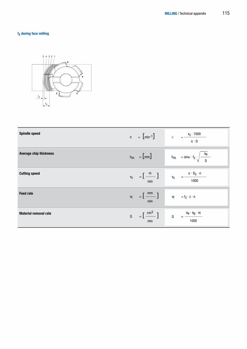
5 4 3 2 1
14
5
32fz
fu
MILLING | Technical appendix
Spindle speed
Average chip thickness
Cutting speed
Feed rate
Material removal rate
fz during face milling
hm = sinκ · fz · ––––ae
D
Q = –––––––
vc = –––––––––
vf = fz · z · n
� · Dc · n
1000
vc · 1000
� · D
vc = [ –––– ]m
min
vf = [ –––– ]mm
min
Q = [ –––– ]cm3
min
hm = [mm]
n = –––––––––n = [min-1]
ae · ap · vf
1000
115

fz
r2
ae
r1
fz
rap
a e fzhm
ap
a e
fz
hm
MILLING | Technical appendix
Trochoidal milling – basic principles
Definition Trochoidal milling is a milling strategy with the objective of reducing pro-cess forces and at the same time increasing the material removal rate. By superimposing a circular movement of the tool on the feed movement, the contact conditions can be improved. Material is removed cyclically with changing contact conditions that can be matched to the tool usage as well as variable cutting widths along the circular path of the tool.
Conventional milling During roughing with full contact the contact conditions for the milling cut-ter are defined at a wrap angle of 180°.
Along with the production of longer chips, this results in a comparatively high load on the tool due to the long tooth contact. The resulting large cut-ting cross-section also results in high machining forces, as a consequence the infeed depths, feeds and cutting speeds for a stable process are limited.
Trochoidal milling The specific kinematics of trochoidal milling make it possible, due to super-imposing a circular movement of the tool on the feed movement, to improve the contact conditions. The contact angle is correspondingly low.
This technological approach has the consequence that a reduced cutting width and cut length result in significantly reduced process forces. In this way it is in turn possible to realise greater cutting depths.
ap: small (cutting depth ~1xD)ae: large (1xD)fz: smallvc: low
ap: large (full utilisation of the cutting edge length possible)ae: smallfz: largevc: high
Example, full slot milling
116

n
/2
h m
ae
vf
fz
D
25,3º
40,5º
56,9º63
,5º
47,3º17,7º
ae
32,6º8,4º
52,9º
52,1º52
,4º
34,1º
14,7º
80 100 120 140 160 1806040200Fräserposition der trochoiden Bahn [º]
OptimalerArbeitsbereich
r1 = 0,5r1 = 1r1 = 1,5r1 = 2r1 = 2,5r1 = 3
OptimalerArbeitsbereich
50 100 1500Fräserposition entlang des Kreisbogens [º]
Kreisbahn ae konstant
optimierte trochoide BahnkurveSpanmittendicke konstant
MILLING | Technical appendix
Trochoidal milling – in detail
Trochoidal milling – circular path In the case of a circular path with constant radius, the wrap angles at the tool cutting edge vary as a function of the absolute radial material removal rate within one revolution.
- Contact conditions change continuously - Optimal working area for the milling cutter - Limited to a small area - Low material removal rate - Increased tendency to vibration - Increased tool wear
For holistic process optimisation, along with the tool path, the movements in the air cut during machining must also be considered. The goal is, after the milling cutter leaves the material, to realise a movement to the next entry point that is as fast as possible. As a circular path is not advantageous at this point, a path as direct as possible is selected depending on the dynamic behaviour of the machine.
Trochoidal milling – optimised path curve Due to the adapted path movement of the tool, the milling cutter's contact ratio can be maintained con-stant at every point on the path over almost the entire machining operation. In this way the milling process can always be operated at the optimal point. Within a path the feed is adjusted such that the average chip thickness remains constant.
- Constant contact conditions - Constant force level - Lower tool wear - Maximum material removal rate
Feed movement – optimised air cut
Average chip thickness hm and contact angle φ
Contact angle φ = [°]Is dependent on the contact ratio ae/D and islimited subject to the workpiece material.
Average
chip thickness hm = [mm]
Is maintained almost constant during trochoidalmilling by means of dynamic feed.The average chip thickness is measured at φ/2.
Feed per
tooth fz = [ mm ]
Limited variable, is adjusted by the CAM systemduring the machining.
Contact width ae = [mm]Is continuously re-calculated by the CAMsoftware and limits the contact angle φ.
Tool diameter
D = [mm]
NOTE
- Trochoidal milling requires, along with a modern
CAM system or a modern machine control
system, also a machining centre that is as
dynamic as possible.
- Full performance is achieved by using OptiMill
milling cutters from the Trochoid series.
Wrapping as a function of the path position – circular path
Wrapping as a function of the path position – optimise path curve
Feed direction
Feed direction
Wrapping subject to the path position and the path radius
Wrapping subject to the path position - conventional circular path and optimised path curve
FeedRampRapid traverse
Optimalmachining range
Cutter position of trochoidal path [°]
Cutter position along the circular arc. [°]
Optimalmachining range
Circular path ae constant
Optimal trochoidal path curverchip thickness constant
cosφ = 1 - 2 · ae
D
hm = fz · ae
D
tooth
117
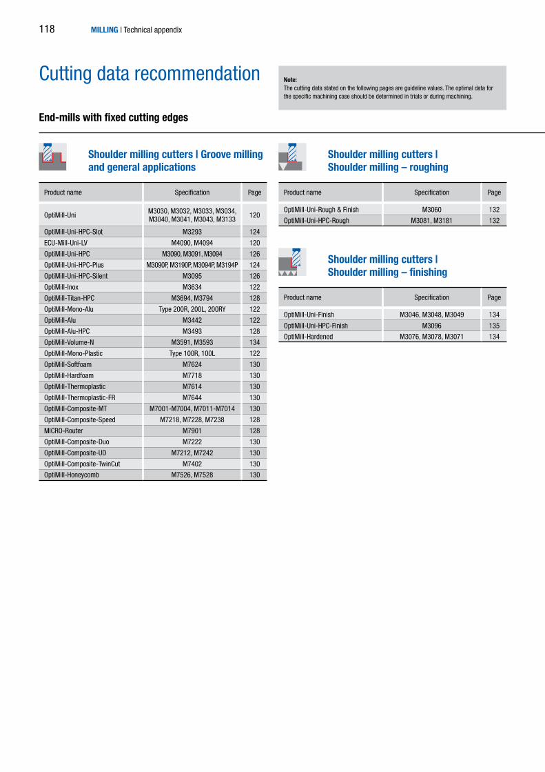
Cutting data recommendation
MILLING | Technical appendix
OptiMill-Uni M3030, M3032, M3033, M3034, M3040, M3041, M3043, M3133 120
OptiMill-Uni-HPC-Slot M3293 124
ECU-Mill-Uni-LV M4090, M4094 120
OptiMill-Uni-HPC M3090, M3091, M3094 126
OptiMill-Uni-HPC-Plus M3090P, M3190P, M3094P, M3194P 124
OptiMill-Uni-HPC-Silent M3095 126
OptiMill-Inox M3634 122
OptiMill-Titan-HPC M3694, M3794 128
OptiMill-Mono-Alu Type 200R, 200L, 200RY 122
OptiMill-Alu M3442 122
OptiMill-Alu-HPC M3493 128
OptiMill-Volume-N M3591, M3593 134
OptiMill-Mono-Plastic Type 100R, 100L 122
OptiMill-Softfoam M7624 130
OptiMill-Hardfoam M7718 130
OptiMill-Thermoplastic M7614 130
OptiMill-Thermoplastic-FR M7644 130
OptiMill-Composite-MT M7001-M7004, M7011-M7014 130
OptiMill-Composite-Speed M7218, M7228, M7238 128
MICRO-Router M7901 128
OptiMill-Composite-Duo M7222 130
OptiMill-Composite-UD M7212, M7242 130
OptiMill-Composite-TwinCut M7402 130
OptiMill-Honeycomb M7526, M7528 130
OptiMill-Uni-Rough & Finish M3060 132
OptiMill-Uni-HPC-Rough M3081, M3181 132
OptiMill-Uni-Finish M3046, M3048, M3049 134
OptiMill-Uni-HPC-Finish M3096 135
OptiMill-Hardened M3076, M3078, M3071 134
Product name Specification Page Product name Specification Page
Product name Specification Page
End-mills with fixed cutting edges
Shoulder milling cutters | Groove milling and general applications
Shoulder milling cutters | Shoulder milling – roughing
Shoulder milling cutters | Shoulder milling – finishing
Note: The cutting data stated on the following pages are guideline values. The optimal data for the specific machining case should be determined in trials or during machining.
118

MILLING | Technical appendix
OptiMill-Uni-Radius M3832 138
OptiMill-Hardened-Radius M3872 139
OptiMill-Composite-MT-Radius M7801 130
OptiMill-Tro-Uni M3099 136
OptiMill-Tro-PM M3299 136
OptiMill-Tro-S M3699 136
OptiMill-Tro-Titan M3799 136
OptiMill-Tro-H M3079 136
OptiMill-Chamfer M5390 139
OptiMill-DrillMill M5490 140
Product name Specification Page
Product name Specification Page Product name Specification Page
End-mills with fixed cutting edges
Profile milling
Shoulder milling cutters | Trochoidal milling
Chamfering, deburringand drill milling
119

ae
a p
ECU-Mill-Uni-LV | M4090, M4094
OptiMill-Uni | M3030, M3032, M3033, M3034, M3040, M3041, M3043, M3133
* MILLER machining groups
ap = 1 x Dae = 1 x D
Groove millingTool length/ Correction factor:Length fz & vc
Short 1Long 0,9Overlong 0,8Extra long 0,6
MILLING | Technical appendix
Cutting data recommendation for shoulder milling cuttersFeed and cutting speed
MMG* Material Strength/hardness[N/mm²]
[HRC]
Cooling vc[m/min]
fz [mm/tooth] vc[m/min]
fz [mm/tooth] vc[m/min]
fz [mm/tooth]
MQL
/air
Dry
Wet Milling cutter diameter [mm] Milling cutter diameter [mm] Milling cutter diameter [mm]
2 4 6 8 10 12 16 20 2 4 6 8 10 12 16 20 2 4 6 8 10 12 16 20
P
P1P1.1 Structural, free-cutting, case hardened and heat-treated steel, non-alloyed < 700 170 0,012 0,021 0,03 0,038 0,046 0,054 0,067 0,078 345 0,02 0,035 0,05 0,065 0,078 0,091 0,114 0,132 505 0,031 0,056 0,079 0,102 0,124 0,144 0,18 0,209
P1.2 Structural, free-cutting, case hardened and heat-treated steel, non-alloyed < 1200 140 0,011 0,019 0,028 0,036 0,043 0,05 0,063 0,073 280 0,019 0,033 0,047 0,06 0,073 0,085 0,106 0,123 415 0,029 0,052 0,074 0,095 0,115 0,135 0,168 0,195
P2P2.1 Nitrated, case hardened and heat-treated steel, alloyed < 900 155 0,012 0,021 0,03 0,038 0,046 0,054 0,067 0,078 315 0,02 0,035 0,05 0,065 0,078 0,091 0,114 0,132 460 0,031 0,056 0,079 0,102 0,124 0,144 0,18 0,209
P2.2 Nitrated, case hardened and heat-treated steel, alloyed < 1400 105 0,01 0,017 0,025 0,032 0,038 0,045 0,056 0,065 220 0,017 0,029 0,042 0,054 0,065 0,076 0,095 0,11 320 0,026 0,046 0,066 0,085 0,103 0,12 0,15 0,174
P3P3.1 Tool, roller bearing, spring and high speed steel < 900 100 0,011 0,02 0,028 0,036 0,044 0,051 0,064 0,074 205 0,019 0,033 0,048 0,061 0,074 0,087 0,108 0,126 300 0,03 0,053 0,075 0,097 0,118 0,137 0,171 0,199
P3.2 Tool, roller bearing, spring and high speed steel < 1500 85 0,01 0,018 0,026 0,033 0,04 0,047 0,058 0,068 170 0,017 0,031 0,043 0,056 0,068 0,079 0,099 0,115 250 0,027 0,048 0,069 0,088 0,107 0,125 0,156 0,181
P4 P4.1 Stainless steel, ferritic and martensitic 70 0,008 0,014 0,02 0,025 0,031 0,036 0,045 0,052 140 0,013 0,023 0,033 0,043 0,052 0,061 0,076 0,088 205 0,021 0,037 0,053 0,068 0,082 0,096 0,12 0,139
P5 P5.1 Cast steel 105 0,011 0,02 0,029 0,037 0,045 0,052 0,065 0,075 210 0,019 0,034 0,048 0,062 0,076 0,088 0,11 0,128 310 0,03 0,054 0,077 0,099 0,12 0,139 0,174 0,202
P6 P6.1 Stainless cast steel, ferritic and martensitic 70 0,005 0,01 0,014 0,018 0,022 0,025 0,031 0,036 140 0,009 0,016 0,023 0,03 0,037 0,043 0,053 0,062 205 0,015 0,026 0,037 0,048 0,058 0,067 0,084 0,098
MM1
M1.1 Stainless steel, austenitic < 700 45 0,007 0,012 0,017 0,022 0,027 0,031 0,039 0,045 95 0,012 0,021 0,029 0,038 0,046 0,053 0,067 0,077 140 0,018 0,032 0,046 0,06 0,072 0,084 0,105 0,122
M1.2 Stainless steel, ferritic/austenitic (Duplex) < 1000 45 0,006 0,01 0,014 0,018 0,022 0,026 0,033 0,038 90 0,01 0,017 0,024 0,031 0,038 0,044 0,055 0,064 130 0,015 0,027 0,038 0,049 0,06 0,07 0,087 0,101
M2 M2.1 Stainless cast steel, austenitic < 700 50 0,007 0,013 0,019 0,024 0,029 0,034 0,043 0,049 105 0,013 0,022 0,032 0,041 0,05 0,058 0,072 0,084 150 0,02 0,035 0,05 0,065 0,078 0,091 0,114 0,132
M3 M3.1 Stainless cast steel, ferritic/austenitic (Duplex) < 1000 45 0,006 0,01 0,015 0,019 0,023 0,027 0,034 0,039 95 0,01 0,018 0,025 0,032 0,039 0,046 0,057 0,066 140 0,016 0,028 0,04 0,051 0,062 0,072 0,09 0,105
K
K1 K1.1 Cast iron with lamellar graphite (grey cast iron), EN-GJL < 300 185 0,02 0,035 0,049 0,063 0,077 0,09 0,112 0,13 375 0,033 0,059 0,084 0,108 0,13 0,152 0,19 0,22 550 0,052 0,093 0,132 0,17 0,206 0,24 0,301 0,348
K2
K2.1 Cast iron with spheroidal graphite, EN-GJS < 500 170 0,017 0,029 0,042 0,054 0,065 0,076 0,095 0,11 345 0,028 0,05 0,071 0,091 0,111 0,129 0,162 0,187 505 0,045 0,079 0,112 0,145 0,175 0,204 0,256 0,296
K2.2 Cast iron with spheroidal graphite , EN-GJS 500-800 140 0,014 0,024 0,034 0,044 0,054 0,063 0,078 0,091 280 0,023 0,041 0,059 0,075 0,091 0,106 0,133 0,154 415 0,037 0,065 0,092 0,119 0,144 0,168 0,21 0,244
K2.3 Cast iron with spheroidal graphite , EN-GJS > 800 75 0,008 0,014 0,02 0,025 0,031 0,036 0,045 0,052 155 0,013 0,023 0,033 0,043 0,052 0,061 0,076 0,088 230 0,021 0,037 0,053 0,068 0,082 0,096 0,12 0,139
K3K3.1 Cast iron with vermicular graphite, EN-GJV; Malleable cast iron, GJM < 500 120 0,014 0,024 0,034 0,044 0,054 0,063 0,078 0,091 250 0,023 0,041 0,059 0,075 0,091 0,106 0,133 0,154 365 0,037 0,065 0,092 0,119 0,144 0,168 0,21 0,244
K3.2 Cast iron with vermicular graphite, EN-GJV; Malleable cast iron, GJM > 500 115 0,012 0,021 0,03 0,038 0,046 0,054 0,067 0,078 235 0,02 0,035 0,05 0,065 0,078 0,091 0,114 0,132 345 0,031 0,056 0,079 0,102 0,124 0,144 0,18 0,209
P
P1P1.1 Structural, free-cutting, case hardened and heat-treated steel, non-alloyed < 700 140 0,01 0,018 0,026 0,034 0,041 0,048 0,06 0,069 285 0,018 0,031 0,045 0,057 0,07 0,081 0,101 0,118 415 0,028 0,05 0,07 0,091 0,11 0,128 0,16 0,186
P1.2 Structural, free-cutting, case hardened and heat-treated steel, non-alloyed < 1200 115 0,01 0,017 0,025 0,032 0,038 0,045 0,056 0,065 230 0,017 0,029 0,042 0,054 0,065 0,076 0,095 0,11 340 0,026 0,046 0,066 0,085 0,103 0,12 0,15 0,173
P2P2.1 Nitrated, case hardened and heat-treated steel, alloyed < 900 125 0,01 0,018 0,026 0,034 0,041 0,048 0,06 0,069 260 0,018 0,031 0,045 0,057 0,07 0,081 0,101 0,118 380 0,028 0,05 0,07 0,091 0,11 0,128 0,16 0,186
P2.2 Nitrated, case hardened and heat-treated steel, alloyed < 1400 90 0,009 0,015 0,022 0,028 0,034 0,04 0,05 0,058 180 0,015 0,026 0,037 0,048 0,058 0,068 0,085 0,098 265 0,023 0,041 0,059 0,076 0,092 0,107 0,134 0,155
P3P3.1 Tool, roller bearing, spring and high speed steel < 900 80 0,01 0,018 0,025 0,032 0,039 0,045 0,057 0,066 165 0,017 0,03 0,042 0,054 0,066 0,077 0,096 0,112 245 0,027 0,047 0,067 0,086 0,104 0,122 0,152 0,177
P3.2 Tool, roller bearing, spring and high speed steel < 1500 70 0,009 0,016 0,023 0,029 0,036 0,041 0,052 0,06 140 0,015 0,027 0,039 0,05 0,06 0,07 0,088 0,102 210 0,024 0,043 0,061 0,079 0,095 0,111 0,139 0,161
P4 P4.1 Stainless steel, ferritic and martensitic 55 0,007 0,012 0,018 0,023 0,027 0,032 0,04 0,046 115 0,012 0,021 0,03 0,038 0,046 0,054 0,068 0,078 170 0,019 0,033 0,047 0,06 0,073 0,085 0,107 0,124
P5 P5.1 Cast steel 85 0,01 0,018 0,025 0,033 0,04 0,046 0,058 0,067 175 0,017 0,03 0,043 0,055 0,067 0,078 0,098 0,114 255 0,027 0,048 0,068 0,088 0,106 0,124 0,155 0,18
P6 P6.1 Stainless cast steel, ferritic and martensitic 55 0,005 0,009 0,012 0,016 0,019 0,022 0,028 0,032 115 0,008 0,015 0,021 0,027 0,032 0,038 0,047 0,055 170 0,013 0,023 0,033 0,042 0,051 0,06 0,075 0,087
MM1
M1.1 Stainless steel, austenitic < 700 40 0,006 0,011 0,015 0,02 0,024 0,028 0,035 0,04 75 0,01 0,018 0,026 0,033 0,041 0,047 0,059 0,069 115 0,016 0,029 0,041 0,053 0,064 0,075 0,094 0,108
M1.2 Stainless steel, ferritic/austenitic (Duplex) < 1000 35 0,005 0,009 0,013 0,016 0,02 0,023 0,029 0,033 70 0,009 0,015 0,022 0,028 0,034 0,039 0,049 0,057 105 0,014 0,024 0,034 0,044 0,053 0,062 0,077 0,09
M2 M2.1 Stainless cast steel, austenitic < 700 40 0,007 0,012 0,017 0,021 0,026 0,03 0,038 0,044 85 0,011 0,02 0,028 0,036 0,044 0,051 0,064 0,074 125 0,018 0,031 0,045 0,057 0,07 0,081 0,102 0,118
M3 M3.1 Stainless cast steel, ferritic/austenitic (Duplex) < 1000 40 0,005 0,009 0,013 0,017 0,021 0,024 0,03 0,035 75 0,009 0,016 0,022 0,029 0,035 0,041 0,051 0,059 115 0,014 0,025 0,035 0,045 0,055 0,064 0,08 0,093
K
K1 K1.1 Cast iron with lamellar graphite (grey cast iron), EN-GJL < 300 150 0,017 0,031 0,044 0,056 0,068 0,08 0,1 0,115 310 0,03 0,052 0,074 0,096 0,116 0,135 0,169 0,196 455 0,047 0,083 0,117 0,151 0,183 0,214 0,267 0,31
K2
K2.1 Cast iron with spheroidal graphite, EN-GJS < 500 140 0,015 0,026 0,037 0,048 0,058 0,068 0,085 0,098 285 0,025 0,044 0,063 0,081 0,099 0,115 0,144 0,166 415 0,04 0,07 0,1 0,128 0,156 0,182 0,227 0,263
K2.2 Cast iron with spheroidal graphite , EN-GJS 500-800 115 0,012 0,022 0,031 0,039 0,048 0,056 0,07 0,081 230 0,021 0,037 0,052 0,067 0,081 0,095 0,118 0,137 340 0,033 0,058 0,082 0,106 0,128 0,149 0,187 0,217
K2.3 Cast iron with spheroidal graphite , EN-GJS > 800 65 0,007 0,012 0,018 0,023 0,027 0,032 0,04 0,046 130 0,012 0,021 0,03 0,038 0,046 0,054 0,068 0,078 190 0,019 0,033 0,047 0,06 0,073 0,085 0,107 0,124
K3K3.1 Cast iron with vermicular graphite, EN-GJV; Malleable cast iron, GJM < 500 100 0,012 0,022 0,031 0,039 0,048 0,056 0,07 0,081 205 0,021 0,037 0,052 0,067 0,081 0,095 0,118 0,137 300 0,033 0,058 0,082 0,106 0,128 0,149 0,187 0,217
K3.2 Cast iron with vermicular graphite, EN-GJV; Malleable cast iron, GJM > 500 95 0,01 0,018 0,026 0,034 0,041 0,048 0,06 0,069 195 0,018 0,031 0,045 0,057 0,07 0,081 0,101 0,118 285 0,028 0,05 0,07 0,091 0,11 0,128 0,16 0,186
N
N1
N1.1 Aluminium, non-alloyed and alloyed <3% Si 525 0,017 0,031 0,044 0,056 0,068 0,08 0,1 0,115 1075 0,03 0,052 0,074 0,096 0,116 0,135 0,169 0,196 1580 0,047 0,083 0,117 0,151 0,183 0,214 0,267 0,31
N1.2 Aluminium, alloyed <=7% Si 350 0,018 0,032 0,046 0,059 0,072 0,084 0,105 0,121 715 0,031 0,055 0,078 0,1 0,122 0,142 0,177 0,206 1050 0,049 0,087 0,123 0,159 0,192 0,224 0,281 0,325
N1.3 Aluminium, alloyed > 7-12% Si 280 0,019 0,034 0,048 0,062 0,075 0,088 0,11 0,127 570 0,032 0,057 0,082 0,105 0,128 0,149 0,186 0,215 840 0,051 0,091 0,129 0,166 0,202 0,235 0,294 0,341
N1.4 Aluminium, alloyed > 12% Si 200 0,021 0,037 0,053 0,068 0,082 0,096 0,12 0,139 410 0,035 0,063 0,089 0,115 0,139 0,162 0,203 0,235 605 0,056 0,099 0,141 0,181 0,22 0,256 0,321 0,372
N2
N2.1 Copper, non-alloyed and low alloyed < 300 200 0,014 0,025 0,035 0,045 0,055 0,064 0,08 0,092 410 0,024 0,042 0,059 0,076 0,093 0,108 0,135 0,157 605 0,037 0,066 0,094 0,121 0,147 0,171 0,214 0,248
N2.2 Copper, alloyed > 300 150 0,014 0,025 0,035 0,045 0,055 0,064 0,08 0,092 310 0,024 0,042 0,059 0,076 0,093 0,108 0,135 0,157 455 0,037 0,066 0,094 0,121 0,147 0,171 0,214 0,248
N2.3 Brass, bronze, gun metal < 1200 250 0,009 0,015 0,022 0,028 0,034 0,04 0,05 0,058 515 0,015 0,026 0,037 0,048 0,058 0,068 0,085 0,098 755 0,023 0,041 0,059 0,076 0,092 0,107 0,134 0,155
120

ae
a p
ae
a p
ap = 1,5 x Dae = 0,25 x D
ap = 1,5 x Dae = 0,1 x D
Roughing Finishing
MILLING | Technical appendix
MMG* Material Strength/hardness[N/mm²]
[HRC]
Cooling vc[m/min]
fz [mm/tooth] vc[m/min]
fz [mm/tooth] vc[m/min]
fz [mm/tooth]
MQL
/air
Dry
Wet Milling cutter diameter [mm] Milling cutter diameter [mm] Milling cutter diameter [mm]
2 4 6 8 10 12 16 20 2 4 6 8 10 12 16 20 2 4 6 8 10 12 16 20
P
P1P1.1 Structural, free-cutting, case hardened and heat-treated steel, non-alloyed < 700 170 0,012 0,021 0,03 0,038 0,046 0,054 0,067 0,078 345 0,02 0,035 0,05 0,065 0,078 0,091 0,114 0,132 505 0,031 0,056 0,079 0,102 0,124 0,144 0,18 0,209
P1.2 Structural, free-cutting, case hardened and heat-treated steel, non-alloyed < 1200 140 0,011 0,019 0,028 0,036 0,043 0,05 0,063 0,073 280 0,019 0,033 0,047 0,06 0,073 0,085 0,106 0,123 415 0,029 0,052 0,074 0,095 0,115 0,135 0,168 0,195
P2P2.1 Nitrated, case hardened and heat-treated steel, alloyed < 900 155 0,012 0,021 0,03 0,038 0,046 0,054 0,067 0,078 315 0,02 0,035 0,05 0,065 0,078 0,091 0,114 0,132 460 0,031 0,056 0,079 0,102 0,124 0,144 0,18 0,209
P2.2 Nitrated, case hardened and heat-treated steel, alloyed < 1400 105 0,01 0,017 0,025 0,032 0,038 0,045 0,056 0,065 220 0,017 0,029 0,042 0,054 0,065 0,076 0,095 0,11 320 0,026 0,046 0,066 0,085 0,103 0,12 0,15 0,174
P3P3.1 Tool, roller bearing, spring and high speed steel < 900 100 0,011 0,02 0,028 0,036 0,044 0,051 0,064 0,074 205 0,019 0,033 0,048 0,061 0,074 0,087 0,108 0,126 300 0,03 0,053 0,075 0,097 0,118 0,137 0,171 0,199
P3.2 Tool, roller bearing, spring and high speed steel < 1500 85 0,01 0,018 0,026 0,033 0,04 0,047 0,058 0,068 170 0,017 0,031 0,043 0,056 0,068 0,079 0,099 0,115 250 0,027 0,048 0,069 0,088 0,107 0,125 0,156 0,181
P4 P4.1 Stainless steel, ferritic and martensitic 70 0,008 0,014 0,02 0,025 0,031 0,036 0,045 0,052 140 0,013 0,023 0,033 0,043 0,052 0,061 0,076 0,088 205 0,021 0,037 0,053 0,068 0,082 0,096 0,12 0,139
P5 P5.1 Cast steel 105 0,011 0,02 0,029 0,037 0,045 0,052 0,065 0,075 210 0,019 0,034 0,048 0,062 0,076 0,088 0,11 0,128 310 0,03 0,054 0,077 0,099 0,12 0,139 0,174 0,202
P6 P6.1 Stainless cast steel, ferritic and martensitic 70 0,005 0,01 0,014 0,018 0,022 0,025 0,031 0,036 140 0,009 0,016 0,023 0,03 0,037 0,043 0,053 0,062 205 0,015 0,026 0,037 0,048 0,058 0,067 0,084 0,098
MM1
M1.1 Stainless steel, austenitic < 700 45 0,007 0,012 0,017 0,022 0,027 0,031 0,039 0,045 95 0,012 0,021 0,029 0,038 0,046 0,053 0,067 0,077 140 0,018 0,032 0,046 0,06 0,072 0,084 0,105 0,122
M1.2 Stainless steel, ferritic/austenitic (Duplex) < 1000 45 0,006 0,01 0,014 0,018 0,022 0,026 0,033 0,038 90 0,01 0,017 0,024 0,031 0,038 0,044 0,055 0,064 130 0,015 0,027 0,038 0,049 0,06 0,07 0,087 0,101
M2 M2.1 Stainless cast steel, austenitic < 700 50 0,007 0,013 0,019 0,024 0,029 0,034 0,043 0,049 105 0,013 0,022 0,032 0,041 0,05 0,058 0,072 0,084 150 0,02 0,035 0,05 0,065 0,078 0,091 0,114 0,132
M3 M3.1 Stainless cast steel, ferritic/austenitic (Duplex) < 1000 45 0,006 0,01 0,015 0,019 0,023 0,027 0,034 0,039 95 0,01 0,018 0,025 0,032 0,039 0,046 0,057 0,066 140 0,016 0,028 0,04 0,051 0,062 0,072 0,09 0,105
K
K1 K1.1 Cast iron with lamellar graphite (grey cast iron), EN-GJL < 300 185 0,02 0,035 0,049 0,063 0,077 0,09 0,112 0,13 375 0,033 0,059 0,084 0,108 0,13 0,152 0,19 0,22 550 0,052 0,093 0,132 0,17 0,206 0,24 0,301 0,348
K2
K2.1 Cast iron with spheroidal graphite, EN-GJS < 500 170 0,017 0,029 0,042 0,054 0,065 0,076 0,095 0,11 345 0,028 0,05 0,071 0,091 0,111 0,129 0,162 0,187 505 0,045 0,079 0,112 0,145 0,175 0,204 0,256 0,296
K2.2 Cast iron with spheroidal graphite , EN-GJS 500-800 140 0,014 0,024 0,034 0,044 0,054 0,063 0,078 0,091 280 0,023 0,041 0,059 0,075 0,091 0,106 0,133 0,154 415 0,037 0,065 0,092 0,119 0,144 0,168 0,21 0,244
K2.3 Cast iron with spheroidal graphite , EN-GJS > 800 75 0,008 0,014 0,02 0,025 0,031 0,036 0,045 0,052 155 0,013 0,023 0,033 0,043 0,052 0,061 0,076 0,088 230 0,021 0,037 0,053 0,068 0,082 0,096 0,12 0,139
K3K3.1 Cast iron with vermicular graphite, EN-GJV; Malleable cast iron, GJM < 500 120 0,014 0,024 0,034 0,044 0,054 0,063 0,078 0,091 250 0,023 0,041 0,059 0,075 0,091 0,106 0,133 0,154 365 0,037 0,065 0,092 0,119 0,144 0,168 0,21 0,244
K3.2 Cast iron with vermicular graphite, EN-GJV; Malleable cast iron, GJM > 500 115 0,012 0,021 0,03 0,038 0,046 0,054 0,067 0,078 235 0,02 0,035 0,05 0,065 0,078 0,091 0,114 0,132 345 0,031 0,056 0,079 0,102 0,124 0,144 0,18 0,209
P
P1P1.1 Structural, free-cutting, case hardened and heat-treated steel, non-alloyed < 700 140 0,01 0,018 0,026 0,034 0,041 0,048 0,06 0,069 285 0,018 0,031 0,045 0,057 0,07 0,081 0,101 0,118 415 0,028 0,05 0,07 0,091 0,11 0,128 0,16 0,186
P1.2 Structural, free-cutting, case hardened and heat-treated steel, non-alloyed < 1200 115 0,01 0,017 0,025 0,032 0,038 0,045 0,056 0,065 230 0,017 0,029 0,042 0,054 0,065 0,076 0,095 0,11 340 0,026 0,046 0,066 0,085 0,103 0,12 0,15 0,173
P2P2.1 Nitrated, case hardened and heat-treated steel, alloyed < 900 125 0,01 0,018 0,026 0,034 0,041 0,048 0,06 0,069 260 0,018 0,031 0,045 0,057 0,07 0,081 0,101 0,118 380 0,028 0,05 0,07 0,091 0,11 0,128 0,16 0,186
P2.2 Nitrated, case hardened and heat-treated steel, alloyed < 1400 90 0,009 0,015 0,022 0,028 0,034 0,04 0,05 0,058 180 0,015 0,026 0,037 0,048 0,058 0,068 0,085 0,098 265 0,023 0,041 0,059 0,076 0,092 0,107 0,134 0,155
P3P3.1 Tool, roller bearing, spring and high speed steel < 900 80 0,01 0,018 0,025 0,032 0,039 0,045 0,057 0,066 165 0,017 0,03 0,042 0,054 0,066 0,077 0,096 0,112 245 0,027 0,047 0,067 0,086 0,104 0,122 0,152 0,177
P3.2 Tool, roller bearing, spring and high speed steel < 1500 70 0,009 0,016 0,023 0,029 0,036 0,041 0,052 0,06 140 0,015 0,027 0,039 0,05 0,06 0,07 0,088 0,102 210 0,024 0,043 0,061 0,079 0,095 0,111 0,139 0,161
P4 P4.1 Stainless steel, ferritic and martensitic 55 0,007 0,012 0,018 0,023 0,027 0,032 0,04 0,046 115 0,012 0,021 0,03 0,038 0,046 0,054 0,068 0,078 170 0,019 0,033 0,047 0,06 0,073 0,085 0,107 0,124
P5 P5.1 Cast steel 85 0,01 0,018 0,025 0,033 0,04 0,046 0,058 0,067 175 0,017 0,03 0,043 0,055 0,067 0,078 0,098 0,114 255 0,027 0,048 0,068 0,088 0,106 0,124 0,155 0,18
P6 P6.1 Stainless cast steel, ferritic and martensitic 55 0,005 0,009 0,012 0,016 0,019 0,022 0,028 0,032 115 0,008 0,015 0,021 0,027 0,032 0,038 0,047 0,055 170 0,013 0,023 0,033 0,042 0,051 0,06 0,075 0,087
MM1
M1.1 Stainless steel, austenitic < 700 40 0,006 0,011 0,015 0,02 0,024 0,028 0,035 0,04 75 0,01 0,018 0,026 0,033 0,041 0,047 0,059 0,069 115 0,016 0,029 0,041 0,053 0,064 0,075 0,094 0,108
M1.2 Stainless steel, ferritic/austenitic (Duplex) < 1000 35 0,005 0,009 0,013 0,016 0,02 0,023 0,029 0,033 70 0,009 0,015 0,022 0,028 0,034 0,039 0,049 0,057 105 0,014 0,024 0,034 0,044 0,053 0,062 0,077 0,09
M2 M2.1 Stainless cast steel, austenitic < 700 40 0,007 0,012 0,017 0,021 0,026 0,03 0,038 0,044 85 0,011 0,02 0,028 0,036 0,044 0,051 0,064 0,074 125 0,018 0,031 0,045 0,057 0,07 0,081 0,102 0,118
M3 M3.1 Stainless cast steel, ferritic/austenitic (Duplex) < 1000 40 0,005 0,009 0,013 0,017 0,021 0,024 0,03 0,035 75 0,009 0,016 0,022 0,029 0,035 0,041 0,051 0,059 115 0,014 0,025 0,035 0,045 0,055 0,064 0,08 0,093
K
K1 K1.1 Cast iron with lamellar graphite (grey cast iron), EN-GJL < 300 150 0,017 0,031 0,044 0,056 0,068 0,08 0,1 0,115 310 0,03 0,052 0,074 0,096 0,116 0,135 0,169 0,196 455 0,047 0,083 0,117 0,151 0,183 0,214 0,267 0,31
K2
K2.1 Cast iron with spheroidal graphite, EN-GJS < 500 140 0,015 0,026 0,037 0,048 0,058 0,068 0,085 0,098 285 0,025 0,044 0,063 0,081 0,099 0,115 0,144 0,166 415 0,04 0,07 0,1 0,128 0,156 0,182 0,227 0,263
K2.2 Cast iron with spheroidal graphite , EN-GJS 500-800 115 0,012 0,022 0,031 0,039 0,048 0,056 0,07 0,081 230 0,021 0,037 0,052 0,067 0,081 0,095 0,118 0,137 340 0,033 0,058 0,082 0,106 0,128 0,149 0,187 0,217
K2.3 Cast iron with spheroidal graphite , EN-GJS > 800 65 0,007 0,012 0,018 0,023 0,027 0,032 0,04 0,046 130 0,012 0,021 0,03 0,038 0,046 0,054 0,068 0,078 190 0,019 0,033 0,047 0,06 0,073 0,085 0,107 0,124
K3K3.1 Cast iron with vermicular graphite, EN-GJV; Malleable cast iron, GJM < 500 100 0,012 0,022 0,031 0,039 0,048 0,056 0,07 0,081 205 0,021 0,037 0,052 0,067 0,081 0,095 0,118 0,137 300 0,033 0,058 0,082 0,106 0,128 0,149 0,187 0,217
K3.2 Cast iron with vermicular graphite, EN-GJV; Malleable cast iron, GJM > 500 95 0,01 0,018 0,026 0,034 0,041 0,048 0,06 0,069 195 0,018 0,031 0,045 0,057 0,07 0,081 0,101 0,118 285 0,028 0,05 0,07 0,091 0,11 0,128 0,16 0,186
N
N1
N1.1 Aluminium, non-alloyed and alloyed <3% Si 525 0,017 0,031 0,044 0,056 0,068 0,08 0,1 0,115 1075 0,03 0,052 0,074 0,096 0,116 0,135 0,169 0,196 1580 0,047 0,083 0,117 0,151 0,183 0,214 0,267 0,31
N1.2 Aluminium, alloyed <=7% Si 350 0,018 0,032 0,046 0,059 0,072 0,084 0,105 0,121 715 0,031 0,055 0,078 0,1 0,122 0,142 0,177 0,206 1050 0,049 0,087 0,123 0,159 0,192 0,224 0,281 0,325
N1.3 Aluminium, alloyed > 7-12% Si 280 0,019 0,034 0,048 0,062 0,075 0,088 0,11 0,127 570 0,032 0,057 0,082 0,105 0,128 0,149 0,186 0,215 840 0,051 0,091 0,129 0,166 0,202 0,235 0,294 0,341
N1.4 Aluminium, alloyed > 12% Si 200 0,021 0,037 0,053 0,068 0,082 0,096 0,12 0,139 410 0,035 0,063 0,089 0,115 0,139 0,162 0,203 0,235 605 0,056 0,099 0,141 0,181 0,22 0,256 0,321 0,372
N2
N2.1 Copper, non-alloyed and low alloyed < 300 200 0,014 0,025 0,035 0,045 0,055 0,064 0,08 0,092 410 0,024 0,042 0,059 0,076 0,093 0,108 0,135 0,157 605 0,037 0,066 0,094 0,121 0,147 0,171 0,214 0,248
N2.2 Copper, alloyed > 300 150 0,014 0,025 0,035 0,045 0,055 0,064 0,08 0,092 310 0,024 0,042 0,059 0,076 0,093 0,108 0,135 0,157 455 0,037 0,066 0,094 0,121 0,147 0,171 0,214 0,248
N2.3 Brass, bronze, gun metal < 1200 250 0,009 0,015 0,022 0,028 0,034 0,04 0,05 0,058 515 0,015 0,026 0,037 0,048 0,058 0,068 0,085 0,098 755 0,023 0,041 0,059 0,076 0,092 0,107 0,134 0,155
121

ae
a p
MMG* Material Strength/hardness [N/mm²]
[HRC]
Cooling vc[m/min]
fz [mm/tooth] vc[m/min]
fz [mm/tooth] vc[m/min]
fz [mm/tooth]
MQL
/air
Dry
Wet Milling cutter diameter [mm] Milling cutter diameter [mm] Milling cutter diameter [mm]
2 4 6 8 10 12 16 20 2 4 6 8 10 12 16 20 2 4 6 8 10 12 16 20
M
M1M1.1 Stainless steel, austenitic < 700 50 0,007 0,012 0,017 0,022 0,027 0,031 0,039 0,045 100 0,012 0,021 0,029 0,038 0,046 0,053 0,067 0,077 145 0,018 0,032 0,046 0,06 0,072 0,084 0,105 0,122
M1.2 Stainless steel, ferritic/austenitic (Duplex) < 1000 45 0,006 0,01 0,014 0,018 0,022 0,026 0,033 0,038 95 0,01 0,017 0,024 0,031 0,038 0,044 0,055 0,064 135 0,015 0,027 0,038 0,049 0,06 0,07 0,087 0,101
M2 M2.1 Stainless cast steel, austenitic < 700 55 0,007 0,013 0,019 0,024 0,029 0,034 0,043 0,049 110 0,013 0,022 0,032 0,041 0,05 0,058 0,072 0,084 160 0,02 0,035 0,05 0,065 0,078 0,091 0,114 0,132
M3 M3.1 Stainless cast steel, ferritic/austenitic (Duplex) < 1000 50 0,006 0,01 0,015 0,019 0,023 0,027 0,034 0,039 100 0,01 0,018 0,025 0,032 0,039 0,046 0,057 0,066 145 0,016 0,028 0,04 0,051 0,062 0,072 0,09 0,105
S
S1 S1.1 Titanium, titanium alloy < 400 80 0,011 0,019 0,027 0,035 0,042 0,049 0,062 0,071 165 0,018 0,032 0,046 0,059 0,072 0,084 0,105 0,121 245 0,029 0,051 0,073 0,094 0,113 0,132 0,165 0,192
S2S2.1 Titanium, titanium alloy < 1200 75 0,009 0,016 0,022 0,029 0,035 0,04 0,05 0,058 150 0,015 0,026 0,038 0,048 0,059 0,068 0,086 0,099 220 0,024 0,042 0,059 0,077 0,093 0,108 0,135 0,157
S2.2 Titanium, titanium alloy > 1200 50 0,008 0,014 0,02 0,025 0,031 0,036 0,045 0,052 100 0,013 0,023 0,033 0,043 0,052 0,061 0,076 0,088 145 0,021 0,037 0,053 0,068 0,082 0,096 0,12 0,139
S3S3.1 Nickel, non-alloyed and alloyed < 900 30 0,01 0,017 0,025 0,032 0,038 0,045 0,056 0,065 65 0,017 0,029 0,042 0,054 0,065 0,076 0,095 0,11 95 0,026 0,046 0,066 0,085 0,103 0,12 0,15 0,174
S3.2 Nickel, non-alloyed and alloyed > 900 24 0,006 0,01 0,015 0,019 0,023 0,027 0,034 0,039 50 0,01 0,018 0,025 0,032 0,039 0,046 0,057 0,066 75 0,016 0,028 0,04 0,051 0,062 0,072 0,09 0,105
S4 S4.1 Heat resistant super alloys, Ni, Co, and Fe based 24 0,005 0,009 0,012 0,016 0,019 0,022 0,028 0,032 50 0,008 0,015 0,021 0,027 0,033 0,038 0,048 0,055 75 0,013 0,023 0,033 0,043 0,052 0,06 0,075 0,087
S5 S5.1 Tungsten and molybdenum alloys 24 0,008 0,014 0,02 0,025 0,031 0,036 0,045 0,052 50 0,013 0,023 0,033 0,043 0,052 0,061 0,076 0,088 75 0,021 0,037 0,053 0,068 0,082 0,096 0,12 0,139
N
N1
N1.1 Aluminium, non-alloyed and alloyed <3% Si 600 0,017 0,031 0,044 0,056 0,068 0,08 0,1 0,115 1230 0,03 0,052 0,074 0,096 0,116 0,135 0,169 0,196 1805 0,047 0,083 0,117 0,151 0,183 0,214 0,267 0,31
N1.2 Aluminium, alloyed <=7% Si 400 0,018 0,032 0,046 0,059 0,072 0,084 0,105 0,121 820 0,031 0,055 0,078 0,1 0,122 0,142 0,177 0,206 1200 0,049 0,087 0,123 0,159 0,192 0,224 0,281 0,325
N1.3 Aluminium, alloyed > 7-12% Si 320 0,019 0,034 0,048 0,062 0,075 0,088 0,11 0,127 655 0,032 0,057 0,082 0,105 0,128 0,149 0,186 0,215 960 0,051 0,091 0,129 0,166 0,202 0,235 0,294 0,341
N1.4 Aluminium, alloyed > 12% Si 230 0,021 0,037 0,053 0,068 0,082 0,096 0,12 0,139 470 0,035 0,063 0,089 0,115 0,139 0,162 0,203 0,235 690 0,056 0,099 0,141 0,181 0,22 0,256 0,321 0,372
N2
N2.1 Copper, non-alloyed and low alloyed < 300 230 0,014 0,025 0,035 0,045 0,055 0,064 0,08 0,092 470 0,024 0,042 0,059 0,076 0,093 0,108 0,135 0,157 690 0,037 0,066 0,094 0,121 0,147 0,171 0,214 0,248
N2.2 Copper, alloyed > 300 175 0,014 0,025 0,035 0,045 0,055 0,064 0,08 0,092 355 0,024 0,042 0,059 0,076 0,093 0,108 0,135 0,157 520 0,037 0,066 0,094 0,121 0,147 0,171 0,214 0,248
N2.3 Brass, bronze, gun metal < 1200 290 0,009 0,015 0,022 0,028 0,034 0,04 0,05 0,058 590 0,015 0,026 0,037 0,048 0,058 0,068 0,085 0,098 865 0,023 0,041 0,059 0,076 0,092 0,107 0,134 0,155
N4
N4.1 Plastic, thermoplastic 80 0,009 0,015 0,022 0,028 0,034 0,04 0,05 0,058 160 0,015 0,026 0,037 0,048 0,058 0,068 0,085 0,098 240 0,023 0,041 0,059 0,076 0,092 0,107 0,134 0,155
N4.2 Plastic, thermosetting plastic (duroplast) 120 0,009 0,015 0,022 0,028 0,034 0,04 0,05 0,058 240 0,015 0,026 0,037 0,048 0,058 0,068 0,085 0,098 355 0,023 0,041 0,059 0,076 0,092 0,107 0,134 0,155
N4.3 Plastic, foam 960 0,005 0,009 0,013 0,017 0,021 0,024 0,03 0,035 1960 0,009 0,016 0,022 0,029 0,035 0,041 0,051 0,059 2875 0,014 0,025 0,035 0,045 0,055 0,064 0,08 0,093
2 3 4 5 6 8 10 12 2 3 4 5 6 8 10 12 2 3 4 5 6 8 10 12
N
N1
N1.1 Aluminium, non-alloyed and alloyed <3% Si 755 0,043 0,06 0,077 0,093 0,109 0,141 0,171 0,199 1540 0,074 0,102 0,13 0,158 0,186 0,239 0,29 0,338 2255 0,117 0,162 0,206 0,25 0,294 0,378 0,458 0,534
N1.2 Aluminium, alloyed <=7% Si 500 0,046 0,063 0,081 0,098 0,115 0,148 0,179 0,209 1025 0,077 0,107 0,137 0,166 0,195 0,251 0,304 0,355 1500 0,122 0,17 0,217 0,263 0,308 0,397 0,481 0,561
N1.3 Aluminium, alloyed > 7-12% Si 400 0,048 0,066 0,085 0,103 0,12 0,155 0,188 0,219 815 0,081 0,113 0,144 0,174 0,204 0,263 0,319 0,371 1200 0,128 0,178 0,227 0,275 0,323 0,416 0,504 0,587
N1.4 Aluminium, alloyed > 12% Si 290 0,052 0,072 0,092 0,112 0,131 0,169 0,205 0,239 590 0,089 0,123 0,157 0,19 0,223 0,287 0,348 0,405 865 0,14 0,194 0,248 0,3 0,352 0,453 0,55 0,641
N2
N2.1 Copper, non-alloyed and low alloyed < 300 290 0,035 0,048 0,062 0,075 0,088 0,113 0,137 0,159 590 0,059 0,082 0,104 0,127 0,149 0,191 0,232 0,27 865 0,093 0,129 0,165 0,2 0,235 0,302 0,367 0,427
N2.2 Copper, alloyed > 300 215 0,035 0,048 0,062 0,075 0,088 0,113 0,137 0,159 440 0,059 0,082 0,104 0,127 0,149 0,191 0,232 0,27 650 0,093 0,129 0,165 0,2 0,235 0,302 0,367 0,427
N2.3 Brass, bronze, gun metal < 1200 360 0,022 0,03 0,038 0,047 0,055 0,07 0,085 0,1 735 0,037 0,051 0,065 0,079 0,093 0,119 0,145 0,169 1080 0,058 0,081 0,103 0,125 0,147 0,189 0,229 0,267
N4
N4.1 Plastic, thermoplastic 100 0,022 0,03 0,038 0,047 0,055 0,07 0,085 0,1 200 0,037 0,051 0,065 0,079 0,093 0,119 0,145 0,169 295 0,058 0,081 0,103 0,125 0,147 0,189 0,229 0,267
N4.2 Plastic, thermosetting plastic (duroplast) 150 0,022 0,03 0,038 0,047 0,055 0,07 0,085 0,1 300 0,037 0,051 0,065 0,079 0,093 0,119 0,145 0,169 445 0,058 0,081 0,103 0,125 0,147 0,189 0,229 0,267
N4.3 Plastic, foam 1200 0,013 0,018 0,023 0,028 0,033 0,042 0,051 0,06 2450 0,022 0,031 0,039 0,047 0,056 0,072 0,087 0,101 3595 0,035 0,049 0,062 0,075 0,088 0,113 0,137 0,16
N N4
N4.1 Plastic, thermoplastic 100 0,022 0,03 0,038 0,047 0,055 0,07 0,085 0,1 200 0,037 0,051 0,065 0,079 0,093 0,119 0,145 0,169 295 0,058 0,081 0,103 0,125 0,147 0,189 0,229 0,267
N4.2 Plastic, thermosetting plastic (duroplast) 150 0,022 0,03 0,038 0,047 0,055 0,07 0,085 0,1 300 0,037 0,051 0,065 0,079 0,093 0,119 0,145 0,169 445 0,058 0,081 0,103 0,125 0,147 0,189 0,229 0,267
N4.3 Plastic, foam 1200 0,013 0,018 0,023 0,028 0,033 0,042 0,051 0,06 2450 0,022 0,031 0,039 0,047 0,056 0,072 0,087 0,101 3595 0,035 0,049 0,062 0,075 0,088 0,113 0,137 0,16
OptiMill-Inox | M3634
OptiMill-Alu | M3442
OptiMill-Mono-Alu | Type 200R, 200L, 200RY
OptiMill-Mono-Plastic | Type 100R, 100L
* MILLER machining groups
ap = 1 x Dae = 1 x D
Groove milling
MILLING | Technical appendix
Cutting data recommendation for shoulder milling cuttersFeed and cutting speed
122

ae
a p
ae
a p
MMG* Material Strength/hardness [N/mm²]
[HRC]
Cooling vc[m/min]
fz [mm/tooth] vc[m/min]
fz [mm/tooth] vc[m/min]
fz [mm/tooth]
MQL
/air
Dry
Wet Milling cutter diameter [mm] Milling cutter diameter [mm] Milling cutter diameter [mm]
2 4 6 8 10 12 16 20 2 4 6 8 10 12 16 20 2 4 6 8 10 12 16 20
M
M1M1.1 Stainless steel, austenitic < 700 50 0,007 0,012 0,017 0,022 0,027 0,031 0,039 0,045 100 0,012 0,021 0,029 0,038 0,046 0,053 0,067 0,077 145 0,018 0,032 0,046 0,06 0,072 0,084 0,105 0,122
M1.2 Stainless steel, ferritic/austenitic (Duplex) < 1000 45 0,006 0,01 0,014 0,018 0,022 0,026 0,033 0,038 95 0,01 0,017 0,024 0,031 0,038 0,044 0,055 0,064 135 0,015 0,027 0,038 0,049 0,06 0,07 0,087 0,101
M2 M2.1 Stainless cast steel, austenitic < 700 55 0,007 0,013 0,019 0,024 0,029 0,034 0,043 0,049 110 0,013 0,022 0,032 0,041 0,05 0,058 0,072 0,084 160 0,02 0,035 0,05 0,065 0,078 0,091 0,114 0,132
M3 M3.1 Stainless cast steel, ferritic/austenitic (Duplex) < 1000 50 0,006 0,01 0,015 0,019 0,023 0,027 0,034 0,039 100 0,01 0,018 0,025 0,032 0,039 0,046 0,057 0,066 145 0,016 0,028 0,04 0,051 0,062 0,072 0,09 0,105
S
S1 S1.1 Titanium, titanium alloy < 400 80 0,011 0,019 0,027 0,035 0,042 0,049 0,062 0,071 165 0,018 0,032 0,046 0,059 0,072 0,084 0,105 0,121 245 0,029 0,051 0,073 0,094 0,113 0,132 0,165 0,192
S2S2.1 Titanium, titanium alloy < 1200 75 0,009 0,016 0,022 0,029 0,035 0,04 0,05 0,058 150 0,015 0,026 0,038 0,048 0,059 0,068 0,086 0,099 220 0,024 0,042 0,059 0,077 0,093 0,108 0,135 0,157
S2.2 Titanium, titanium alloy > 1200 50 0,008 0,014 0,02 0,025 0,031 0,036 0,045 0,052 100 0,013 0,023 0,033 0,043 0,052 0,061 0,076 0,088 145 0,021 0,037 0,053 0,068 0,082 0,096 0,12 0,139
S3S3.1 Nickel, non-alloyed and alloyed < 900 30 0,01 0,017 0,025 0,032 0,038 0,045 0,056 0,065 65 0,017 0,029 0,042 0,054 0,065 0,076 0,095 0,11 95 0,026 0,046 0,066 0,085 0,103 0,12 0,15 0,174
S3.2 Nickel, non-alloyed and alloyed > 900 24 0,006 0,01 0,015 0,019 0,023 0,027 0,034 0,039 50 0,01 0,018 0,025 0,032 0,039 0,046 0,057 0,066 75 0,016 0,028 0,04 0,051 0,062 0,072 0,09 0,105
S4 S4.1 Heat resistant super alloys, Ni, Co, and Fe based 24 0,005 0,009 0,012 0,016 0,019 0,022 0,028 0,032 50 0,008 0,015 0,021 0,027 0,033 0,038 0,048 0,055 75 0,013 0,023 0,033 0,043 0,052 0,06 0,075 0,087
S5 S5.1 Tungsten and molybdenum alloys 24 0,008 0,014 0,02 0,025 0,031 0,036 0,045 0,052 50 0,013 0,023 0,033 0,043 0,052 0,061 0,076 0,088 75 0,021 0,037 0,053 0,068 0,082 0,096 0,12 0,139
N
N1
N1.1 Aluminium, non-alloyed and alloyed <3% Si 600 0,017 0,031 0,044 0,056 0,068 0,08 0,1 0,115 1230 0,03 0,052 0,074 0,096 0,116 0,135 0,169 0,196 1805 0,047 0,083 0,117 0,151 0,183 0,214 0,267 0,31
N1.2 Aluminium, alloyed <=7% Si 400 0,018 0,032 0,046 0,059 0,072 0,084 0,105 0,121 820 0,031 0,055 0,078 0,1 0,122 0,142 0,177 0,206 1200 0,049 0,087 0,123 0,159 0,192 0,224 0,281 0,325
N1.3 Aluminium, alloyed > 7-12% Si 320 0,019 0,034 0,048 0,062 0,075 0,088 0,11 0,127 655 0,032 0,057 0,082 0,105 0,128 0,149 0,186 0,215 960 0,051 0,091 0,129 0,166 0,202 0,235 0,294 0,341
N1.4 Aluminium, alloyed > 12% Si 230 0,021 0,037 0,053 0,068 0,082 0,096 0,12 0,139 470 0,035 0,063 0,089 0,115 0,139 0,162 0,203 0,235 690 0,056 0,099 0,141 0,181 0,22 0,256 0,321 0,372
N2
N2.1 Copper, non-alloyed and low alloyed < 300 230 0,014 0,025 0,035 0,045 0,055 0,064 0,08 0,092 470 0,024 0,042 0,059 0,076 0,093 0,108 0,135 0,157 690 0,037 0,066 0,094 0,121 0,147 0,171 0,214 0,248
N2.2 Copper, alloyed > 300 175 0,014 0,025 0,035 0,045 0,055 0,064 0,08 0,092 355 0,024 0,042 0,059 0,076 0,093 0,108 0,135 0,157 520 0,037 0,066 0,094 0,121 0,147 0,171 0,214 0,248
N2.3 Brass, bronze, gun metal < 1200 290 0,009 0,015 0,022 0,028 0,034 0,04 0,05 0,058 590 0,015 0,026 0,037 0,048 0,058 0,068 0,085 0,098 865 0,023 0,041 0,059 0,076 0,092 0,107 0,134 0,155
N4
N4.1 Plastic, thermoplastic 80 0,009 0,015 0,022 0,028 0,034 0,04 0,05 0,058 160 0,015 0,026 0,037 0,048 0,058 0,068 0,085 0,098 240 0,023 0,041 0,059 0,076 0,092 0,107 0,134 0,155
N4.2 Plastic, thermosetting plastic (duroplast) 120 0,009 0,015 0,022 0,028 0,034 0,04 0,05 0,058 240 0,015 0,026 0,037 0,048 0,058 0,068 0,085 0,098 355 0,023 0,041 0,059 0,076 0,092 0,107 0,134 0,155
N4.3 Plastic, foam 960 0,005 0,009 0,013 0,017 0,021 0,024 0,03 0,035 1960 0,009 0,016 0,022 0,029 0,035 0,041 0,051 0,059 2875 0,014 0,025 0,035 0,045 0,055 0,064 0,08 0,093
2 3 4 5 6 8 10 12 2 3 4 5 6 8 10 12 2 3 4 5 6 8 10 12
N
N1
N1.1 Aluminium, non-alloyed and alloyed <3% Si 755 0,043 0,06 0,077 0,093 0,109 0,141 0,171 0,199 1540 0,074 0,102 0,13 0,158 0,186 0,239 0,29 0,338 2255 0,117 0,162 0,206 0,25 0,294 0,378 0,458 0,534
N1.2 Aluminium, alloyed <=7% Si 500 0,046 0,063 0,081 0,098 0,115 0,148 0,179 0,209 1025 0,077 0,107 0,137 0,166 0,195 0,251 0,304 0,355 1500 0,122 0,17 0,217 0,263 0,308 0,397 0,481 0,561
N1.3 Aluminium, alloyed > 7-12% Si 400 0,048 0,066 0,085 0,103 0,12 0,155 0,188 0,219 815 0,081 0,113 0,144 0,174 0,204 0,263 0,319 0,371 1200 0,128 0,178 0,227 0,275 0,323 0,416 0,504 0,587
N1.4 Aluminium, alloyed > 12% Si 290 0,052 0,072 0,092 0,112 0,131 0,169 0,205 0,239 590 0,089 0,123 0,157 0,19 0,223 0,287 0,348 0,405 865 0,14 0,194 0,248 0,3 0,352 0,453 0,55 0,641
N2
N2.1 Copper, non-alloyed and low alloyed < 300 290 0,035 0,048 0,062 0,075 0,088 0,113 0,137 0,159 590 0,059 0,082 0,104 0,127 0,149 0,191 0,232 0,27 865 0,093 0,129 0,165 0,2 0,235 0,302 0,367 0,427
N2.2 Copper, alloyed > 300 215 0,035 0,048 0,062 0,075 0,088 0,113 0,137 0,159 440 0,059 0,082 0,104 0,127 0,149 0,191 0,232 0,27 650 0,093 0,129 0,165 0,2 0,235 0,302 0,367 0,427
N2.3 Brass, bronze, gun metal < 1200 360 0,022 0,03 0,038 0,047 0,055 0,07 0,085 0,1 735 0,037 0,051 0,065 0,079 0,093 0,119 0,145 0,169 1080 0,058 0,081 0,103 0,125 0,147 0,189 0,229 0,267
N4
N4.1 Plastic, thermoplastic 100 0,022 0,03 0,038 0,047 0,055 0,07 0,085 0,1 200 0,037 0,051 0,065 0,079 0,093 0,119 0,145 0,169 295 0,058 0,081 0,103 0,125 0,147 0,189 0,229 0,267
N4.2 Plastic, thermosetting plastic (duroplast) 150 0,022 0,03 0,038 0,047 0,055 0,07 0,085 0,1 300 0,037 0,051 0,065 0,079 0,093 0,119 0,145 0,169 445 0,058 0,081 0,103 0,125 0,147 0,189 0,229 0,267
N4.3 Plastic, foam 1200 0,013 0,018 0,023 0,028 0,033 0,042 0,051 0,06 2450 0,022 0,031 0,039 0,047 0,056 0,072 0,087 0,101 3595 0,035 0,049 0,062 0,075 0,088 0,113 0,137 0,16
N N4
N4.1 Plastic, thermoplastic 100 0,022 0,03 0,038 0,047 0,055 0,07 0,085 0,1 200 0,037 0,051 0,065 0,079 0,093 0,119 0,145 0,169 295 0,058 0,081 0,103 0,125 0,147 0,189 0,229 0,267
N4.2 Plastic, thermosetting plastic (duroplast) 150 0,022 0,03 0,038 0,047 0,055 0,07 0,085 0,1 300 0,037 0,051 0,065 0,079 0,093 0,119 0,145 0,169 445 0,058 0,081 0,103 0,125 0,147 0,189 0,229 0,267
N4.3 Plastic, foam 1200 0,013 0,018 0,023 0,028 0,033 0,042 0,051 0,06 2450 0,022 0,031 0,039 0,047 0,056 0,072 0,087 0,101 3595 0,035 0,049 0,062 0,075 0,088 0,113 0,137 0,16
ap = 1,5 x Dae = 0,25 x D
ap = 1,5 x Dae = 0,1 x D
Roughing Finishing
MILLING | Technical appendix 123

ae
a p
MMG* Material Strength/hardness [N/mm²]
[HRC]
Cooling vc[m/min]
fz [mm/tooth] vc[m/min]
fz [mm/tooth] vc[m/min]
fz [mm/tooth]
MQL
/air
Dry
Wet Milling cutter diameter [mm] Milling cutter diameter [mm] Milling cutter diameter [mm]
2 4 6 8 10 12 16 20 2 4 6 8 10 12 16 20 2 4 6 8 10 12 16 20
P
P1P1.1 Structural, free-cutting, case hardened and heat-treated steel, non-alloyed < 700 220 0,016 0,029 0,041 0,053 0,064 0,075 0,093 0,108 445 0,028 0,049 0,07 0,09 0,109 0,127 0,158 0,184 655 0,044 0,077 0,11 0,142 0,172 0,2 0,251 0,29
P1.2 Structural, free-cutting, case hardened and heat-treated steel, non-alloyed < 1200 180 0,015 0,027 0,038 0,049 0,06 0,07 0,087 0,101 365 0,026 0,046 0,065 0,084 0,101 0,118 0,148 0,171 535 0,041 0,072 0,103 0,132 0,16 0,187 0,234 0,271
P2P2.1 Nitrated, case hardened and heat-treated steel, alloyed < 900 200 0,016 0,029 0,041 0,053 0,064 0,075 0,093 0,108 405 0,028 0,049 0,07 0,09 0,109 0,127 0,158 0,184 595 0,044 0,077 0,11 0,142 0,172 0,2 0,251 0,29
P2.2 Nitrated, case hardened and heat-treated steel, alloyed < 1400 140 0,014 0,024 0,034 0,044 0,053 0,062 0,078 0,09 285 0,023 0,041 0,058 0,075 0,091 0,106 0,132 0,153 415 0,036 0,064 0,092 0,118 0,143 0,167 0,209 0,242
P3P3.1 Tool, roller bearing, spring and high speed steel < 900 130 0,015 0,027 0,039 0,05 0,061 0,071 0,089 0,103 265 0,026 0,046 0,066 0,085 0,103 0,12 0,151 0,174 385 0,042 0,073 0,105 0,135 0,163 0,19 0,238 0,276
P3.2 Tool, roller bearing, spring and high speed steel < 1500 110 0,014 0,025 0,036 0,046 0,056 0,065 0,081 0,094 225 0,024 0,042 0,06 0,078 0,094 0,11 0,137 0,159 325 0,038 0,067 0,095 0,123 0,149 0,174 0,217 0,252
P4 P4.1 Stainless steel, ferritic and martensitic 90 0,011 0,019 0,027 0,035 0,043 0,05 0,062 0,072 180 0,018 0,033 0,046 0,06 0,072 0,084 0,106 0,122 265 0,029 0,052 0,073 0,094 0,115 0,133 0,167 0,194
P5 P5.1 Cast steel 135 0,016 0,028 0,04 0,051 0,062 0,072 0,09 0,105 270 0,027 0,047 0,067 0,087 0,105 0,122 0,153 0,177 400 0,042 0,075 0,106 0,137 0,166 0,194 0,242 0,281
P6 P6.1 Stainless cast steel, ferritic and martensitic 90 0,008 0,013 0,019 0,025 0,03 0,035 0,044 0,051 180 0,013 0,023 0,033 0,042 0,051 0,059 0,074 0,086 265 0,02 0,036 0,051 0,066 0,08 0,093 0,117 0,135
M
M1M1.1 Stainless steel, austenitic < 700 60 0,01 0,017 0,024 0,031 0,037 0,044 0,054 0,063 120 0,016 0,029 0,041 0,052 0,063 0,074 0,092 0,107 180 0,026 0,045 0,064 0,083 0,1 0,117 0,146 0,169
M1.2 Stainless steel, ferritic/austenitic (Duplex) < 1000 55 0,008 0,014 0,02 0,026 0,031 0,036 0,045 0,052 115 0,013 0,024 0,034 0,043 0,053 0,061 0,077 0,089 165 0,021 0,037 0,053 0,068 0,083 0,097 0,121 0,14
M2 M2.1 Stainless cast steel, austenitic < 700 65 0,01 0,018 0,026 0,033 0,041 0,047 0,059 0,069 135 0,018 0,031 0,044 0,057 0,069 0,08 0,1 0,116 195 0,028 0,049 0,07 0,09 0,109 0,127 0,159 0,184
M3 M3.1 Stainless cast steel, ferritic/austenitic (Duplex) < 1000 60 0,008 0,014 0,021 0,026 0,032 0,037 0,047 0,054 120 0,014 0,024 0,035 0,045 0,054 0,063 0,079 0,092 180 0,022 0,039 0,055 0,071 0,086 0,1 0,125 0,145
K
K1 K1.1 Cast iron with lamellar graphite (grey cast iron), EN-GJL < 300 240 0,027 0,048 0,068 0,088 0,107 0,124 0,156 0,18 485 0,046 0,082 0,116 0,149 0,181 0,211 0,264 0,306 715 0,073 0,129 0,184 0,236 0,286 0,334 0,418 0,484
K2
K2.1 Cast iron with spheroidal graphite, EN-GJS < 500 220 0,023 0,041 0,058 0,075 0,091 0,106 0,132 0,153 445 0,039 0,069 0,099 0,127 0,154 0,179 0,224 0,26 655 0,062 0,11 0,156 0,201 0,243 0,284 0,355 0,411
K2.2 Cast iron with spheroidal graphite , EN-GJS 500-800 180 0,019 0,034 0,048 0,062 0,075 0,087 0,109 0,126 365 0,032 0,057 0,081 0,105 0,127 0,148 0,185 0,214 535 0,051 0,09 0,128 0,165 0,2 0,234 0,292 0,339
K2.3 Cast iron with spheroidal graphite , EN-GJS > 800 100 0,011 0,019 0,027 0,035 0,043 0,05 0,062 0,072 200 0,018 0,033 0,046 0,06 0,072 0,084 0,106 0,122 295 0,029 0,052 0,073 0,094 0,115 0,133 0,167 0,194
K3K3.1 Cast iron with vermicular graphite, EN-GJV; Malleable cast iron, GJM < 500 160 0,019 0,034 0,048 0,062 0,075 0,087 0,109 0,126 325 0,032 0,057 0,081 0,105 0,127 0,148 0,185 0,214 475 0,051 0,09 0,128 0,165 0,2 0,234 0,292 0,339
K3.2 Cast iron with vermicular graphite, EN-GJV; Malleable cast iron, GJM > 500 150 0,016 0,029 0,041 0,053 0,064 0,075 0,093 0,108 305 0,028 0,049 0,07 0,09 0,109 0,127 0,158 0,184 445 0,044 0,077 0,11 0,142 0,172 0,2 0,251 0,29
P
P1P1.1 Structural, free-cutting, case hardened and heat-treated steel, non-alloyed < 700 200 0,013 0,023 0,033 0,042 0,051 0,06 0,075 0,087 405 0,022 0,039 0,056 0,072 0,087 0,101 0,127 0,147 595 0,035 0,062 0,088 0,113 0,137 0,16 0,2 0,232
P1.2 Structural, free-cutting, case hardened and heat-treated steel, non-alloyed < 1200 160 0,012 0,022 0,031 0,039 0,048 0,056 0,07 0,081 330 0,021 0,037 0,052 0,067 0,081 0,095 0,118 0,137 485 0,033 0,058 0,082 0,106 0,128 0,149 0,187 0,217
P2P2.1 Nitrated, case hardened and heat-treated steel, alloyed < 900 180 0,013 0,023 0,033 0,042 0,051 0,06 0,075 0,087 370 0,022 0,039 0,056 0,072 0,087 0,101 0,127 0,147 540 0,035 0,062 0,088 0,113 0,137 0,16 0,2 0,232
P2.2 Nitrated, case hardened and heat-treated steel, alloyed < 1400 125 0,011 0,019 0,027 0,035 0,043 0,05 0,062 0,072 260 0,018 0,033 0,046 0,06 0,072 0,084 0,106 0,122 380 0,029 0,052 0,073 0,094 0,115 0,133 0,167 0,194
P3P3.1 Tool, roller bearing, spring and high speed steel < 900 115 0,012 0,022 0,031 0,04 0,049 0,057 0,071 0,082 240 0,021 0,037 0,053 0,068 0,083 0,096 0,12 0,14 350 0,033 0,059 0,084 0,108 0,131 0,152 0,19 0,221
P3.2 Tool, roller bearing, spring and high speed steel < 1500 100 0,011 0,02 0,028 0,037 0,044 0,052 0,065 0,075 200 0,019 0,034 0,048 0,062 0,075 0,088 0,11 0,127 295 0,03 0,054 0,076 0,098 0,119 0,139 0,174 0,201
P4 P4.1 Stainless steel, ferritic and martensitic 80 0,009 0,015 0,022 0,028 0,034 0,04 0,05 0,058 165 0,015 0,026 0,037 0,048 0,058 0,068 0,085 0,098 245 0,023 0,041 0,059 0,076 0,092 0,107 0,134 0,155
P5 P5.1 Cast steel 120 0,013 0,022 0,032 0,041 0,05 0,058 0,072 0,084 245 0,021 0,038 0,054 0,069 0,084 0,098 0,123 0,142 360 0,034 0,06 0,085 0,11 0,133 0,155 0,194 0,225
P6 P6.1 Stainless cast steel, ferritic and martensitic 80 0,006 0,011 0,015 0,02 0,024 0,028 0,035 0,04 165 0,01 0,018 0,026 0,033 0,041 0,047 0,059 0,069 245 0,016 0,029 0,041 0,053 0,064 0,075 0,094 0,108
M
M1M1.1 Stainless steel, austenitic < 700 55 0,008 0,013 0,019 0,025 0,03 0,035 0,044 0,051 110 0,013 0,023 0,033 0,042 0,051 0,059 0,074 0,086 160 0,02 0,036 0,051 0,066 0,08 0,093 0,117 0,135
M1.2 Stainless steel, ferritic/austenitic (Duplex) < 1000 50 0,006 0,011 0,016 0,02 0,025 0,029 0,036 0,042 105 0,011 0,019 0,027 0,035 0,042 0,049 0,061 0,071 150 0,017 0,03 0,043 0,055 0,066 0,077 0,097 0,112
M2 M2.1 Stainless cast steel, austenitic < 700 60 0,008 0,015 0,021 0,027 0,032 0,038 0,047 0,055 120 0,014 0,025 0,035 0,045 0,055 0,064 0,08 0,093 180 0,022 0,039 0,056 0,072 0,087 0,101 0,127 0,147
M3 M3.1 Stainless cast steel, ferritic/austenitic (Duplex) < 1000 55 0,007 0,012 0,016 0,021 0,026 0,03 0,037 0,043 110 0,011 0,02 0,028 0,036 0,043 0,051 0,063 0,073 160 0,017 0,031 0,044 0,057 0,069 0,08 0,1 0,116
K
K1 K1.1 Cast iron with lamellar graphite (grey cast iron), EN-GJL < 300 215 0,022 0,038 0,055 0,07 0,085 0,1 0,125 0,144 440 0,037 0,065 0,093 0,119 0,145 0,169 0,211 0,245 650 0,058 0,103 0,147 0,189 0,229 0,267 0,334 0,387
K2
K2.1 Cast iron with spheroidal graphite, EN-GJS < 500 200 0,018 0,033 0,047 0,06 0,073 0,085 0,106 0,123 405 0,031 0,055 0,079 0,102 0,123 0,144 0,18 0,208 595 0,05 0,088 0,125 0,161 0,195 0,227 0,284 0,329
K2.2 Cast iron with spheroidal graphite , EN-GJS 500-800 160 0,015 0,027 0,038 0,049 0,06 0,07 0,087 0,101 330 0,026 0,046 0,065 0,084 0,101 0,118 0,148 0,171 485 0,041 0,072 0,103 0,132 0,16 0,187 0,234 0,271
K2.3 Cast iron with spheroidal graphite , EN-GJS > 800 90 0,009 0,015 0,022 0,028 0,034 0,04 0,05 0,058 185 0,015 0,026 0,037 0,048 0,058 0,068 0,085 0,098 270 0,023 0,041 0,059 0,076 0,092 0,107 0,134 0,155
K3K3.1 Cast iron with vermicular graphite, EN-GJV; Malleable cast iron, GJM < 500 145 0,015 0,027 0,038 0,049 0,06 0,07 0,087 0,101 295 0,026 0,046 0,065 0,084 0,101 0,118 0,148 0,171 430 0,041 0,072 0,103 0,132 0,16 0,187 0,234 0,271
K3.2 Cast iron with vermicular graphite, EN-GJV; Malleable cast iron, GJM > 500 135 0,013 0,023 0,033 0,042 0,051 0,06 0,075 0,087 275 0,022 0,039 0,056 0,072 0,087 0,101 0,127 0,147 405 0,035 0,062 0,088 0,113 0,137 0,16 0,2 0,232
OptiMill-Uni-HPC-Plus | M3090P, M3190P, M3094P, M3194P
OptiMill-Uni-HPC-Slot | M3293
* MILLER machining groups
ap = 1 x Dae = 1 x D
Groove milling
MILLING | Technical appendix
Tool length/ Correction factor:Length fz & vc
Short 1Long 0,9Overlong 0,8Extra long 0,6
Cutting data recommendation for shoulder milling cuttersFeed and cutting speed
124

ae
a p
ae
a p
MMG* Material Strength/hardness [N/mm²]
[HRC]
Cooling vc[m/min]
fz [mm/tooth] vc[m/min]
fz [mm/tooth] vc[m/min]
fz [mm/tooth]
MQL
/air
Dry
Wet Milling cutter diameter [mm] Milling cutter diameter [mm] Milling cutter diameter [mm]
2 4 6 8 10 12 16 20 2 4 6 8 10 12 16 20 2 4 6 8 10 12 16 20
P
P1P1.1 Structural, free-cutting, case hardened and heat-treated steel, non-alloyed < 700 220 0,016 0,029 0,041 0,053 0,064 0,075 0,093 0,108 445 0,028 0,049 0,07 0,09 0,109 0,127 0,158 0,184 655 0,044 0,077 0,11 0,142 0,172 0,2 0,251 0,29
P1.2 Structural, free-cutting, case hardened and heat-treated steel, non-alloyed < 1200 180 0,015 0,027 0,038 0,049 0,06 0,07 0,087 0,101 365 0,026 0,046 0,065 0,084 0,101 0,118 0,148 0,171 535 0,041 0,072 0,103 0,132 0,16 0,187 0,234 0,271
P2P2.1 Nitrated, case hardened and heat-treated steel, alloyed < 900 200 0,016 0,029 0,041 0,053 0,064 0,075 0,093 0,108 405 0,028 0,049 0,07 0,09 0,109 0,127 0,158 0,184 595 0,044 0,077 0,11 0,142 0,172 0,2 0,251 0,29
P2.2 Nitrated, case hardened and heat-treated steel, alloyed < 1400 140 0,014 0,024 0,034 0,044 0,053 0,062 0,078 0,09 285 0,023 0,041 0,058 0,075 0,091 0,106 0,132 0,153 415 0,036 0,064 0,092 0,118 0,143 0,167 0,209 0,242
P3P3.1 Tool, roller bearing, spring and high speed steel < 900 130 0,015 0,027 0,039 0,05 0,061 0,071 0,089 0,103 265 0,026 0,046 0,066 0,085 0,103 0,12 0,151 0,174 385 0,042 0,073 0,105 0,135 0,163 0,19 0,238 0,276
P3.2 Tool, roller bearing, spring and high speed steel < 1500 110 0,014 0,025 0,036 0,046 0,056 0,065 0,081 0,094 225 0,024 0,042 0,06 0,078 0,094 0,11 0,137 0,159 325 0,038 0,067 0,095 0,123 0,149 0,174 0,217 0,252
P4 P4.1 Stainless steel, ferritic and martensitic 90 0,011 0,019 0,027 0,035 0,043 0,05 0,062 0,072 180 0,018 0,033 0,046 0,06 0,072 0,084 0,106 0,122 265 0,029 0,052 0,073 0,094 0,115 0,133 0,167 0,194
P5 P5.1 Cast steel 135 0,016 0,028 0,04 0,051 0,062 0,072 0,09 0,105 270 0,027 0,047 0,067 0,087 0,105 0,122 0,153 0,177 400 0,042 0,075 0,106 0,137 0,166 0,194 0,242 0,281
P6 P6.1 Stainless cast steel, ferritic and martensitic 90 0,008 0,013 0,019 0,025 0,03 0,035 0,044 0,051 180 0,013 0,023 0,033 0,042 0,051 0,059 0,074 0,086 265 0,02 0,036 0,051 0,066 0,08 0,093 0,117 0,135
M
M1M1.1 Stainless steel, austenitic < 700 60 0,01 0,017 0,024 0,031 0,037 0,044 0,054 0,063 120 0,016 0,029 0,041 0,052 0,063 0,074 0,092 0,107 180 0,026 0,045 0,064 0,083 0,1 0,117 0,146 0,169
M1.2 Stainless steel, ferritic/austenitic (Duplex) < 1000 55 0,008 0,014 0,02 0,026 0,031 0,036 0,045 0,052 115 0,013 0,024 0,034 0,043 0,053 0,061 0,077 0,089 165 0,021 0,037 0,053 0,068 0,083 0,097 0,121 0,14
M2 M2.1 Stainless cast steel, austenitic < 700 65 0,01 0,018 0,026 0,033 0,041 0,047 0,059 0,069 135 0,018 0,031 0,044 0,057 0,069 0,08 0,1 0,116 195 0,028 0,049 0,07 0,09 0,109 0,127 0,159 0,184
M3 M3.1 Stainless cast steel, ferritic/austenitic (Duplex) < 1000 60 0,008 0,014 0,021 0,026 0,032 0,037 0,047 0,054 120 0,014 0,024 0,035 0,045 0,054 0,063 0,079 0,092 180 0,022 0,039 0,055 0,071 0,086 0,1 0,125 0,145
K
K1 K1.1 Cast iron with lamellar graphite (grey cast iron), EN-GJL < 300 240 0,027 0,048 0,068 0,088 0,107 0,124 0,156 0,18 485 0,046 0,082 0,116 0,149 0,181 0,211 0,264 0,306 715 0,073 0,129 0,184 0,236 0,286 0,334 0,418 0,484
K2
K2.1 Cast iron with spheroidal graphite, EN-GJS < 500 220 0,023 0,041 0,058 0,075 0,091 0,106 0,132 0,153 445 0,039 0,069 0,099 0,127 0,154 0,179 0,224 0,26 655 0,062 0,11 0,156 0,201 0,243 0,284 0,355 0,411
K2.2 Cast iron with spheroidal graphite , EN-GJS 500-800 180 0,019 0,034 0,048 0,062 0,075 0,087 0,109 0,126 365 0,032 0,057 0,081 0,105 0,127 0,148 0,185 0,214 535 0,051 0,09 0,128 0,165 0,2 0,234 0,292 0,339
K2.3 Cast iron with spheroidal graphite , EN-GJS > 800 100 0,011 0,019 0,027 0,035 0,043 0,05 0,062 0,072 200 0,018 0,033 0,046 0,06 0,072 0,084 0,106 0,122 295 0,029 0,052 0,073 0,094 0,115 0,133 0,167 0,194
K3K3.1 Cast iron with vermicular graphite, EN-GJV; Malleable cast iron, GJM < 500 160 0,019 0,034 0,048 0,062 0,075 0,087 0,109 0,126 325 0,032 0,057 0,081 0,105 0,127 0,148 0,185 0,214 475 0,051 0,09 0,128 0,165 0,2 0,234 0,292 0,339
K3.2 Cast iron with vermicular graphite, EN-GJV; Malleable cast iron, GJM > 500 150 0,016 0,029 0,041 0,053 0,064 0,075 0,093 0,108 305 0,028 0,049 0,07 0,09 0,109 0,127 0,158 0,184 445 0,044 0,077 0,11 0,142 0,172 0,2 0,251 0,29
P
P1P1.1 Structural, free-cutting, case hardened and heat-treated steel, non-alloyed < 700 200 0,013 0,023 0,033 0,042 0,051 0,06 0,075 0,087 405 0,022 0,039 0,056 0,072 0,087 0,101 0,127 0,147 595 0,035 0,062 0,088 0,113 0,137 0,16 0,2 0,232
P1.2 Structural, free-cutting, case hardened and heat-treated steel, non-alloyed < 1200 160 0,012 0,022 0,031 0,039 0,048 0,056 0,07 0,081 330 0,021 0,037 0,052 0,067 0,081 0,095 0,118 0,137 485 0,033 0,058 0,082 0,106 0,128 0,149 0,187 0,217
P2P2.1 Nitrated, case hardened and heat-treated steel, alloyed < 900 180 0,013 0,023 0,033 0,042 0,051 0,06 0,075 0,087 370 0,022 0,039 0,056 0,072 0,087 0,101 0,127 0,147 540 0,035 0,062 0,088 0,113 0,137 0,16 0,2 0,232
P2.2 Nitrated, case hardened and heat-treated steel, alloyed < 1400 125 0,011 0,019 0,027 0,035 0,043 0,05 0,062 0,072 260 0,018 0,033 0,046 0,06 0,072 0,084 0,106 0,122 380 0,029 0,052 0,073 0,094 0,115 0,133 0,167 0,194
P3P3.1 Tool, roller bearing, spring and high speed steel < 900 115 0,012 0,022 0,031 0,04 0,049 0,057 0,071 0,082 240 0,021 0,037 0,053 0,068 0,083 0,096 0,12 0,14 350 0,033 0,059 0,084 0,108 0,131 0,152 0,19 0,221
P3.2 Tool, roller bearing, spring and high speed steel < 1500 100 0,011 0,02 0,028 0,037 0,044 0,052 0,065 0,075 200 0,019 0,034 0,048 0,062 0,075 0,088 0,11 0,127 295 0,03 0,054 0,076 0,098 0,119 0,139 0,174 0,201
P4 P4.1 Stainless steel, ferritic and martensitic 80 0,009 0,015 0,022 0,028 0,034 0,04 0,05 0,058 165 0,015 0,026 0,037 0,048 0,058 0,068 0,085 0,098 245 0,023 0,041 0,059 0,076 0,092 0,107 0,134 0,155
P5 P5.1 Cast steel 120 0,013 0,022 0,032 0,041 0,05 0,058 0,072 0,084 245 0,021 0,038 0,054 0,069 0,084 0,098 0,123 0,142 360 0,034 0,06 0,085 0,11 0,133 0,155 0,194 0,225
P6 P6.1 Stainless cast steel, ferritic and martensitic 80 0,006 0,011 0,015 0,02 0,024 0,028 0,035 0,04 165 0,01 0,018 0,026 0,033 0,041 0,047 0,059 0,069 245 0,016 0,029 0,041 0,053 0,064 0,075 0,094 0,108
M
M1M1.1 Stainless steel, austenitic < 700 55 0,008 0,013 0,019 0,025 0,03 0,035 0,044 0,051 110 0,013 0,023 0,033 0,042 0,051 0,059 0,074 0,086 160 0,02 0,036 0,051 0,066 0,08 0,093 0,117 0,135
M1.2 Stainless steel, ferritic/austenitic (Duplex) < 1000 50 0,006 0,011 0,016 0,02 0,025 0,029 0,036 0,042 105 0,011 0,019 0,027 0,035 0,042 0,049 0,061 0,071 150 0,017 0,03 0,043 0,055 0,066 0,077 0,097 0,112
M2 M2.1 Stainless cast steel, austenitic < 700 60 0,008 0,015 0,021 0,027 0,032 0,038 0,047 0,055 120 0,014 0,025 0,035 0,045 0,055 0,064 0,08 0,093 180 0,022 0,039 0,056 0,072 0,087 0,101 0,127 0,147
M3 M3.1 Stainless cast steel, ferritic/austenitic (Duplex) < 1000 55 0,007 0,012 0,016 0,021 0,026 0,03 0,037 0,043 110 0,011 0,02 0,028 0,036 0,043 0,051 0,063 0,073 160 0,017 0,031 0,044 0,057 0,069 0,08 0,1 0,116
K
K1 K1.1 Cast iron with lamellar graphite (grey cast iron), EN-GJL < 300 215 0,022 0,038 0,055 0,07 0,085 0,1 0,125 0,144 440 0,037 0,065 0,093 0,119 0,145 0,169 0,211 0,245 650 0,058 0,103 0,147 0,189 0,229 0,267 0,334 0,387
K2
K2.1 Cast iron with spheroidal graphite, EN-GJS < 500 200 0,018 0,033 0,047 0,06 0,073 0,085 0,106 0,123 405 0,031 0,055 0,079 0,102 0,123 0,144 0,18 0,208 595 0,05 0,088 0,125 0,161 0,195 0,227 0,284 0,329
K2.2 Cast iron with spheroidal graphite , EN-GJS 500-800 160 0,015 0,027 0,038 0,049 0,06 0,07 0,087 0,101 330 0,026 0,046 0,065 0,084 0,101 0,118 0,148 0,171 485 0,041 0,072 0,103 0,132 0,16 0,187 0,234 0,271
K2.3 Cast iron with spheroidal graphite , EN-GJS > 800 90 0,009 0,015 0,022 0,028 0,034 0,04 0,05 0,058 185 0,015 0,026 0,037 0,048 0,058 0,068 0,085 0,098 270 0,023 0,041 0,059 0,076 0,092 0,107 0,134 0,155
K3K3.1 Cast iron with vermicular graphite, EN-GJV; Malleable cast iron, GJM < 500 145 0,015 0,027 0,038 0,049 0,06 0,07 0,087 0,101 295 0,026 0,046 0,065 0,084 0,101 0,118 0,148 0,171 430 0,041 0,072 0,103 0,132 0,16 0,187 0,234 0,271
K3.2 Cast iron with vermicular graphite, EN-GJV; Malleable cast iron, GJM > 500 135 0,013 0,023 0,033 0,042 0,051 0,06 0,075 0,087 275 0,022 0,039 0,056 0,072 0,087 0,101 0,127 0,147 405 0,035 0,062 0,088 0,113 0,137 0,16 0,2 0,232
ap = 1,5 x Dae = 0,25 x D
ap = 1,5 x Dae = 0,1 x D
Roughing Finishing
MILLING | Technical appendix 125

ae
a p
Cutting data recommendation for shoulder milling cuttersFeed and cutting speed
MMG* Material Strength/hardness [N/mm²]
[HRC]
Cooling vc[m/min]
fz [mm/tooth] vc[m/min]
fz [mm/tooth] vc[m/min]
fz [mm/tooth]
MQL
/air
Dry
Wet Milling cutter diameter [mm] Milling cutter diameter [mm] Milling cutter diameter [mm]
2 4 6 8 10 12 16 20 25 2 4 6 8 10 12 16 20 25 2 4 6 8 10 12 16 20 25
P
P1P1.1 Structural, free-cutting, case hardened and heat-treated steel, non-alloyed < 700 200 0,013 0,023 0,033 0,042 0,051 0,060 0,075 0,087 0,096 405 0,022 0,039 0,056 0,072 0,087 0,101 0,127 0,147 0,163 595 0,035 0,062 0,088 0,113 0,137 0,160 0,200 0,232 0,257
P1.2 Structural, free-cutting, case hardened and heat-treated steel, non-alloyed < 1200 160 0,012 0,022 0,031 0,039 0,048 0,056 0,070 0,081 0,090 330 0,021 0,037 0,052 0,067 0,081 0,095 0,118 0,137 0,152 485 0,033 0,058 0,082 0,106 0,128 0,149 0,187 0,217 0,240
P2P2.1 Nitrated, case hardened and heat-treated steel, alloyed < 900 180 0,013 0,023 0,033 0,042 0,051 0,060 0,075 0,087 0,096 370 0,022 0,039 0,056 0,072 0,087 0,101 0,127 0,147 0,163 540 0,035 0,062 0,088 0,113 0,137 0,160 0,200 0,232 0,257
P2.2 Nitrated, case hardened and heat-treated steel, alloyed < 1400 125 0,011 0,019 0,027 0,035 0,043 0,050 0,062 0,072 0,080 260 0,018 0,033 0,046 0,060 0,072 0,084 0,106 0,122 0,136 380 0,029 0,052 0,073 0,094 0,115 0,133 0,167 0,194 0,214
P3P3.1 Tool, roller bearing, spring and high speed steel < 900 115 0,012 0,022 0,031 0,040 0,049 0,057 0,071 0,082 0,091 240 0,021 0,037 0,053 0,068 0,083 0,096 0,120 0,140 0,155 350 0,033 0,059 0,084 0,108 0,131 0,152 0,190 0,221 0,244
P3.2 Tool, roller bearing, spring and high speed steel < 1500 100 0,011 0,020 0,028 0,037 0,044 0,052 0,065 0,075 0,083 200 0,019 0,034 0,048 0,062 0,075 0,088 0,110 0,127 0,141 295 0,030 0,054 0,076 0,098 0,119 0,139 0,174 0,201 0,223
P4 P4.1 Stainless steel, ferritic and martensitic 80 0,009 0,015 0,022 0,028 0,034 0,040 0,050 0,058 0,064 165 0,015 0,026 0,037 0,048 0,058 0,068 0,085 0,098 0,108 245 0,023 0,041 0,059 0,076 0,092 0,107 0,134 0,155 0,172
P5 P5.1 Cast steel 120 0,013 0,022 0,032 0,041 0,050 0,058 0,072 0,084 0,093 245 0,021 0,038 0,054 0,069 0,084 0,098 0,123 0,142 0,157 360 0,034 0,060 0,085 0,110 0,133 0,155 0,194 0,225 0,249
P6 P6.1 Stainless cast steel, ferritic and martensitic 80 0,006 0,011 0,015 0,020 0,024 0,028 0,035 0,040 0,045 165 0,010 0,018 0,026 0,033 0,041 0,047 0,059 0,069 0,076 245 0,016 0,029 0,041 0,053 0,064 0,075 0,094 0,108 0,120
MM1
M1.1 Stainless steel, austenitic < 700 55 0,008 0,013 0,019 0,025 0,030 0,035 0,044 0,051 0,056 110 0,013 0,023 0,033 0,042 0,051 0,059 0,074 0,086 0,095 160 0,020 0,036 0,051 0,066 0,080 0,093 0,117 0,135 0,150
M1.2 Stainless steel, ferritic/austenitic (Duplex) < 1000 50 0,006 0,011 0,016 0,020 0,025 0,029 0,036 0,042 0,046 105 0,011 0,019 0,027 0,035 0,042 0,049 0,061 0,071 0,079 150 0,017 0,030 0,043 0,055 0,066 0,077 0,097 0,112 0,124
M2 M2.1 Stainless cast steel, austenitic < 700 60 0,008 0,015 0,021 0,027 0,032 0,038 0,047 0,055 0,061 120 0,014 0,025 0,035 0,045 0,055 0,064 0,080 0,093 0,103 180 0,022 0,039 0,056 0,072 0,087 0,101 0,127 0,147 0,163
M3 M3.1 Stainless cast steel, ferritic/austenitic (Duplex) < 1000 55 0,007 0,012 0,016 0,021 0,026 0,030 0,037 0,043 0,048 110 0,011 0,020 0,028 0,036 0,043 0,051 0,063 0,073 0,081 160 0,017 0,031 0,044 0,057 0,069 0,080 0,100 0,116 0,129
K
K1 K1.1 Cast iron with lamellar graphite (grey cast iron), EN-GJL < 300 215 0,022 0,038 0,055 0,070 0,085 0,100 0,125 0,144 0,160 440 0,037 0,065 0,093 0,119 0,145 0,169 0,211 0,245 0,271 650 0,058 0,103 0,147 0,189 0,229 0,267 0,334 0,387 0,429
K2
K2.1 Cast iron with spheroidal graphite, EN-GJS < 500 200 0,018 0,033 0,047 0,060 0,073 0,085 0,106 0,123 0,136 405 0,031 0,055 0,079 0,102 0,123 0,144 0,180 0,208 0,231 595 0,050 0,088 0,125 0,161 0,195 0,227 0,284 0,329 0,365
K2.2 Cast iron with spheroidal graphite , EN-GJS 500-800 160 0,015 0,027 0,038 0,049 0,060 0,070 0,087 0,101 0,112 330 0,026 0,046 0,065 0,084 0,101 0,118 0,148 0,171 0,190 485 0,041 0,072 0,103 0,132 0,160 0,187 0,234 0,271 0,300
K2.3 Cast iron with spheroidal graphite , EN-GJS > 800 90 0,009 0,015 0,022 0,028 0,034 0,040 0,050 0,058 0,064 185 0,015 0,026 0,037 0,048 0,058 0,068 0,085 0,098 0,108 270 0,023 0,041 0,059 0,076 0,092 0,107 0,134 0,155 0,172
K3K3.1 Cast iron with vermicular graphite, EN-GJV; Malleable cast iron, GJM < 500 145 0,015 0,027 0,038 0,049 0,060 0,070 0,087 0,101 0,112 295 0,026 0,046 0,065 0,084 0,101 0,118 0,148 0,171 0,190 430 0,041 0,072 0,103 0,132 0,160 0,187 0,234 0,271 0,300
K3.2 Cast iron with vermicular graphite, EN-GJV; Malleable cast iron, GJM > 500 135 0,013 0,023 0,033 0,042 0,051 0,060 0,075 0,087 0,096 275 0,022 0,039 0,056 0,072 0,087 0,101 0,127 0,147 0,163 405 0,035 0,062 0,088 0,113 0,137 0,160 0,200 0,232 0,257
OptiMill-Uni-HPC | M3090, M3091, M3094
* MILLER machining groups
ap = 1 x Dae = 0,6 x D
Groove milling – partial slot
MILLING | Technical appendix
Tool length/ Correction factor:Length fz & vc
Short 1Long 0,9Overlong 0,8Extra long 0,6
P
P1P1.1 Structural, free-cutting, case hardened and heat-treated steel, non-alloyed < 700 230 – – 0,042 0,055 0,066 0,077 0,096 0,112 0,124 405 – – 0,056 0,072 0,087 0,101 0,127 0,147 0,163 595 – – 0,088 0,113 0,137 0,16 0,2 0,232 0,257
P1.2 Structural, free-cutting, case hardened and heat-treated steel, non-alloyed < 1200 190 – – 0,04 0,051 0,062 0,072 0,09 0,104 0,116 330 – – 0,052 0,067 0,081 0,095 0,118 0,137 0,152 485 – – 0,082 0,106 0,128 0,149 0,187 0,217 0,24
P2P2.1 Nitrated, case hardened and heat-treated steel, alloyed < 900 210 – – 0,042 0,055 0,066 0,077 0,096 0,112 0,124 370 – – 0,056 0,072 0,087 0,101 0,127 0,147 0,163 540 – – 0,088 0,113 0,137 0,16 0,2 0,232 0,257
P2.2 Nitrated, case hardened and heat-treated steel, alloyed < 1400 145 – – 0,035 0,045 0,055 0,064 0,08 0,093 0,103 260 – – 0,046 0,06 0,072 0,084 0,106 0,122 0,136 380 – – 0,073 0,094 0,115 0,133 0,167 0,194 0,214
P3P3.1 Tool, roller bearing, spring and high speed steel < 900 135 – – 0,04 0,052 0,063 0,073 0,092 0,106 0,118 240 – – 0,053 0,068 0,083 0,096 0,12 0,14 0,155 350 – – 0,084 0,108 0,131 0,152 0,19 0,221 0,244
P3.2 Tool, roller bearing, spring and high speed steel < 1500 115 – – 0,037 0,047 0,057 0,067 0,084 0,097 0,107 200 – – 0,048 0,062 0,075 0,088 0,11 0,127 0,141 295 – – 0,076 0,098 0,119 0,139 0,174 0,201 0,223
P4 P4.1 Stainless steel, ferritic and martensitic 95 – – 0,028 0,036 0,044 0,051 0,064 0,075 0,083 165 – – 0,037 0,048 0,058 0,068 0,085 0,098 0,108 245 – – 0,059 0,076 0,092 0,107 0,134 0,155 0,172
P5 P5.1 Cast steel 140 – – 0,041 0,053 0,064 0,075 0,093 0,108 0,12 245 – – 0,054 0,069 0,084 0,098 0,123 0,142 0,157 360 – – 0,085 0,11 0,133 0,155 0,194 0,225 0,249
P6 P6.1 Stainless cast steel, ferritic and martensitic 95 – – 0,02 0,025 0,031 0,036 0,045 0,052 0,058 165 – – 0,026 0,033 0,041 0,047 0,059 0,069 0,076 245 – – 0,041 0,053 0,064 0,075 0,094 0,108 0,12
M
M1M1.1 Stainless steel, austenitic < 700 65 – – 0,025 0,032 0,039 0,045 0,056 0,065 0,072 110 – – 0,033 0,042 0,051 0,059 0,074 0,086 0,095 160 – – 0,051 0,066 0,08 0,093 0,117 0,135 0,15
M1.2 Stainless steel, ferritic/austenitic (Duplex) < 1000 60 – – 0,02 0,026 0,032 0,037 0,047 0,054 0,06 105 – – 0,027 0,035 0,042 0,049 0,061 0,071 0,079 150 – – 0,043 0,055 0,066 0,077 0,097 0,112 0,124
M2 M2.1 Stainless cast steel, austenitic < 700 70 – – 0,027 0,035 0,042 0,049 0,061 0,071 0,078 120 – – 0,035 0,045 0,055 0,064 0,08 0,093 0,103 180 – – 0,056 0,072 0,087 0,101 0,127 0,147 0,163
M3 M3.1 Stainless cast steel, ferritic/austenitic (Duplex) < 1000 65 – – 0,021 0,027 0,033 0,039 0,048 0,056 0,062 110 – – 0,028 0,036 0,043 0,051 0,063 0,073 0,081 160 – – 0,044 0,057 0,069 0,08 0,1 0,116 0,129
K
K1 K1.1 Cast iron with lamellar graphite (grey cast iron), EN-GJL < 300 250 – – 0,071 0,091 0,11 0,128 0,161 0,186 0,206 440 – – 0,093 0,119 0,145 0,169 0,211 0,245 0,271 650 – – 0,147 0,189 0,229 0,267 0,334 0,387 0,429
K2
K2.1 Cast iron with spheroidal graphite, EN-GJS < 500 230 – – 0,06 0,077 0,094 0,109 0,137 0,158 0,175 405 – – 0,079 0,102 0,123 0,144 0,18 0,208 0,231 595 – – 0,125 0,161 0,195 0,227 0,284 0,329 0,365
K2.2 Cast iron with spheroidal graphite , EN-GJS 500-800 190 – – 0,049 0,064 0,077 0,09 0,113 0,13 0,144 330 – – 0,065 0,084 0,101 0,118 0,148 0,171 0,19 485 – – 0,103 0,132 0,16 0,187 0,234 0,271 0,3
K2.3 Cast iron with spheroidal graphite , EN-GJS > 800 105 – – 0,028 0,036 0,044 0,051 0,064 0,075 0,083 185 – – 0,037 0,048 0,058 0,068 0,085 0,098 0,108 270 – – 0,059 0,076 0,092 0,107 0,134 0,155 0,172
K3K3.1 Cast iron with vermicular graphite, EN-GJV; Malleable cast iron, GJM < 500 170 – – 0,049 0,064 0,077 0,09 0,113 0,13 0,144 295 – – 0,065 0,084 0,101 0,118 0,148 0,171 0,19 430 – – 0,103 0,132 0,16 0,187 0,234 0,271 0,3
K3.2 Cast iron with vermicular graphite, EN-GJV; Malleable cast iron, GJM > 500 160 – – 0,042 0,055 0,066 0,077 0,096 0,112 0,124 275 – – 0,056 0,072 0,087 0,101 0,127 0,147 0,163 405 – – 0,088 0,113 0,137 0,16 0,2 0,232 0,257
OptiMill-Uni-HPC-Silent | M3095
126

ae
a p
ae
a p
MMG* Material Strength/hardness [N/mm²]
[HRC]
Cooling vc[m/min]
fz [mm/tooth] vc[m/min]
fz [mm/tooth] vc[m/min]
fz [mm/tooth]
MQL
/air
Dry
Wet Milling cutter diameter [mm] Milling cutter diameter [mm] Milling cutter diameter [mm]
2 4 6 8 10 12 16 20 25 2 4 6 8 10 12 16 20 25 2 4 6 8 10 12 16 20 25
P
P1P1.1 Structural, free-cutting, case hardened and heat-treated steel, non-alloyed < 700 200 0,013 0,023 0,033 0,042 0,051 0,060 0,075 0,087 0,096 405 0,022 0,039 0,056 0,072 0,087 0,101 0,127 0,147 0,163 595 0,035 0,062 0,088 0,113 0,137 0,160 0,200 0,232 0,257
P1.2 Structural, free-cutting, case hardened and heat-treated steel, non-alloyed < 1200 160 0,012 0,022 0,031 0,039 0,048 0,056 0,070 0,081 0,090 330 0,021 0,037 0,052 0,067 0,081 0,095 0,118 0,137 0,152 485 0,033 0,058 0,082 0,106 0,128 0,149 0,187 0,217 0,240
P2P2.1 Nitrated, case hardened and heat-treated steel, alloyed < 900 180 0,013 0,023 0,033 0,042 0,051 0,060 0,075 0,087 0,096 370 0,022 0,039 0,056 0,072 0,087 0,101 0,127 0,147 0,163 540 0,035 0,062 0,088 0,113 0,137 0,160 0,200 0,232 0,257
P2.2 Nitrated, case hardened and heat-treated steel, alloyed < 1400 125 0,011 0,019 0,027 0,035 0,043 0,050 0,062 0,072 0,080 260 0,018 0,033 0,046 0,060 0,072 0,084 0,106 0,122 0,136 380 0,029 0,052 0,073 0,094 0,115 0,133 0,167 0,194 0,214
P3P3.1 Tool, roller bearing, spring and high speed steel < 900 115 0,012 0,022 0,031 0,040 0,049 0,057 0,071 0,082 0,091 240 0,021 0,037 0,053 0,068 0,083 0,096 0,120 0,140 0,155 350 0,033 0,059 0,084 0,108 0,131 0,152 0,190 0,221 0,244
P3.2 Tool, roller bearing, spring and high speed steel < 1500 100 0,011 0,020 0,028 0,037 0,044 0,052 0,065 0,075 0,083 200 0,019 0,034 0,048 0,062 0,075 0,088 0,110 0,127 0,141 295 0,030 0,054 0,076 0,098 0,119 0,139 0,174 0,201 0,223
P4 P4.1 Stainless steel, ferritic and martensitic 80 0,009 0,015 0,022 0,028 0,034 0,040 0,050 0,058 0,064 165 0,015 0,026 0,037 0,048 0,058 0,068 0,085 0,098 0,108 245 0,023 0,041 0,059 0,076 0,092 0,107 0,134 0,155 0,172
P5 P5.1 Cast steel 120 0,013 0,022 0,032 0,041 0,050 0,058 0,072 0,084 0,093 245 0,021 0,038 0,054 0,069 0,084 0,098 0,123 0,142 0,157 360 0,034 0,060 0,085 0,110 0,133 0,155 0,194 0,225 0,249
P6 P6.1 Stainless cast steel, ferritic and martensitic 80 0,006 0,011 0,015 0,020 0,024 0,028 0,035 0,040 0,045 165 0,010 0,018 0,026 0,033 0,041 0,047 0,059 0,069 0,076 245 0,016 0,029 0,041 0,053 0,064 0,075 0,094 0,108 0,120
MM1
M1.1 Stainless steel, austenitic < 700 55 0,008 0,013 0,019 0,025 0,030 0,035 0,044 0,051 0,056 110 0,013 0,023 0,033 0,042 0,051 0,059 0,074 0,086 0,095 160 0,020 0,036 0,051 0,066 0,080 0,093 0,117 0,135 0,150
M1.2 Stainless steel, ferritic/austenitic (Duplex) < 1000 50 0,006 0,011 0,016 0,020 0,025 0,029 0,036 0,042 0,046 105 0,011 0,019 0,027 0,035 0,042 0,049 0,061 0,071 0,079 150 0,017 0,030 0,043 0,055 0,066 0,077 0,097 0,112 0,124
M2 M2.1 Stainless cast steel, austenitic < 700 60 0,008 0,015 0,021 0,027 0,032 0,038 0,047 0,055 0,061 120 0,014 0,025 0,035 0,045 0,055 0,064 0,080 0,093 0,103 180 0,022 0,039 0,056 0,072 0,087 0,101 0,127 0,147 0,163
M3 M3.1 Stainless cast steel, ferritic/austenitic (Duplex) < 1000 55 0,007 0,012 0,016 0,021 0,026 0,030 0,037 0,043 0,048 110 0,011 0,020 0,028 0,036 0,043 0,051 0,063 0,073 0,081 160 0,017 0,031 0,044 0,057 0,069 0,080 0,100 0,116 0,129
K
K1 K1.1 Cast iron with lamellar graphite (grey cast iron), EN-GJL < 300 215 0,022 0,038 0,055 0,070 0,085 0,100 0,125 0,144 0,160 440 0,037 0,065 0,093 0,119 0,145 0,169 0,211 0,245 0,271 650 0,058 0,103 0,147 0,189 0,229 0,267 0,334 0,387 0,429
K2
K2.1 Cast iron with spheroidal graphite, EN-GJS < 500 200 0,018 0,033 0,047 0,060 0,073 0,085 0,106 0,123 0,136 405 0,031 0,055 0,079 0,102 0,123 0,144 0,180 0,208 0,231 595 0,050 0,088 0,125 0,161 0,195 0,227 0,284 0,329 0,365
K2.2 Cast iron with spheroidal graphite , EN-GJS 500-800 160 0,015 0,027 0,038 0,049 0,060 0,070 0,087 0,101 0,112 330 0,026 0,046 0,065 0,084 0,101 0,118 0,148 0,171 0,190 485 0,041 0,072 0,103 0,132 0,160 0,187 0,234 0,271 0,300
K2.3 Cast iron with spheroidal graphite , EN-GJS > 800 90 0,009 0,015 0,022 0,028 0,034 0,040 0,050 0,058 0,064 185 0,015 0,026 0,037 0,048 0,058 0,068 0,085 0,098 0,108 270 0,023 0,041 0,059 0,076 0,092 0,107 0,134 0,155 0,172
K3K3.1 Cast iron with vermicular graphite, EN-GJV; Malleable cast iron, GJM < 500 145 0,015 0,027 0,038 0,049 0,060 0,070 0,087 0,101 0,112 295 0,026 0,046 0,065 0,084 0,101 0,118 0,148 0,171 0,190 430 0,041 0,072 0,103 0,132 0,160 0,187 0,234 0,271 0,300
K3.2 Cast iron with vermicular graphite, EN-GJV; Malleable cast iron, GJM > 500 135 0,013 0,023 0,033 0,042 0,051 0,060 0,075 0,087 0,096 275 0,022 0,039 0,056 0,072 0,087 0,101 0,127 0,147 0,163 405 0,035 0,062 0,088 0,113 0,137 0,160 0,200 0,232 0,257
ap = 1,5 x Dae = 0,25 x D
ap = 1,5 x Dae = 0,1 x D
Roughing Finishing
MILLING | Technical appendix
P
P1P1.1 Structural, free-cutting, case hardened and heat-treated steel, non-alloyed < 700 230 – – 0,042 0,055 0,066 0,077 0,096 0,112 0,124 405 – – 0,056 0,072 0,087 0,101 0,127 0,147 0,163 595 – – 0,088 0,113 0,137 0,16 0,2 0,232 0,257
P1.2 Structural, free-cutting, case hardened and heat-treated steel, non-alloyed < 1200 190 – – 0,04 0,051 0,062 0,072 0,09 0,104 0,116 330 – – 0,052 0,067 0,081 0,095 0,118 0,137 0,152 485 – – 0,082 0,106 0,128 0,149 0,187 0,217 0,24
P2P2.1 Nitrated, case hardened and heat-treated steel, alloyed < 900 210 – – 0,042 0,055 0,066 0,077 0,096 0,112 0,124 370 – – 0,056 0,072 0,087 0,101 0,127 0,147 0,163 540 – – 0,088 0,113 0,137 0,16 0,2 0,232 0,257
P2.2 Nitrated, case hardened and heat-treated steel, alloyed < 1400 145 – – 0,035 0,045 0,055 0,064 0,08 0,093 0,103 260 – – 0,046 0,06 0,072 0,084 0,106 0,122 0,136 380 – – 0,073 0,094 0,115 0,133 0,167 0,194 0,214
P3P3.1 Tool, roller bearing, spring and high speed steel < 900 135 – – 0,04 0,052 0,063 0,073 0,092 0,106 0,118 240 – – 0,053 0,068 0,083 0,096 0,12 0,14 0,155 350 – – 0,084 0,108 0,131 0,152 0,19 0,221 0,244
P3.2 Tool, roller bearing, spring and high speed steel < 1500 115 – – 0,037 0,047 0,057 0,067 0,084 0,097 0,107 200 – – 0,048 0,062 0,075 0,088 0,11 0,127 0,141 295 – – 0,076 0,098 0,119 0,139 0,174 0,201 0,223
P4 P4.1 Stainless steel, ferritic and martensitic 95 – – 0,028 0,036 0,044 0,051 0,064 0,075 0,083 165 – – 0,037 0,048 0,058 0,068 0,085 0,098 0,108 245 – – 0,059 0,076 0,092 0,107 0,134 0,155 0,172
P5 P5.1 Cast steel 140 – – 0,041 0,053 0,064 0,075 0,093 0,108 0,12 245 – – 0,054 0,069 0,084 0,098 0,123 0,142 0,157 360 – – 0,085 0,11 0,133 0,155 0,194 0,225 0,249
P6 P6.1 Stainless cast steel, ferritic and martensitic 95 – – 0,02 0,025 0,031 0,036 0,045 0,052 0,058 165 – – 0,026 0,033 0,041 0,047 0,059 0,069 0,076 245 – – 0,041 0,053 0,064 0,075 0,094 0,108 0,12
M
M1M1.1 Stainless steel, austenitic < 700 65 – – 0,025 0,032 0,039 0,045 0,056 0,065 0,072 110 – – 0,033 0,042 0,051 0,059 0,074 0,086 0,095 160 – – 0,051 0,066 0,08 0,093 0,117 0,135 0,15
M1.2 Stainless steel, ferritic/austenitic (Duplex) < 1000 60 – – 0,02 0,026 0,032 0,037 0,047 0,054 0,06 105 – – 0,027 0,035 0,042 0,049 0,061 0,071 0,079 150 – – 0,043 0,055 0,066 0,077 0,097 0,112 0,124
M2 M2.1 Stainless cast steel, austenitic < 700 70 – – 0,027 0,035 0,042 0,049 0,061 0,071 0,078 120 – – 0,035 0,045 0,055 0,064 0,08 0,093 0,103 180 – – 0,056 0,072 0,087 0,101 0,127 0,147 0,163
M3 M3.1 Stainless cast steel, ferritic/austenitic (Duplex) < 1000 65 – – 0,021 0,027 0,033 0,039 0,048 0,056 0,062 110 – – 0,028 0,036 0,043 0,051 0,063 0,073 0,081 160 – – 0,044 0,057 0,069 0,08 0,1 0,116 0,129
K
K1 K1.1 Cast iron with lamellar graphite (grey cast iron), EN-GJL < 300 250 – – 0,071 0,091 0,11 0,128 0,161 0,186 0,206 440 – – 0,093 0,119 0,145 0,169 0,211 0,245 0,271 650 – – 0,147 0,189 0,229 0,267 0,334 0,387 0,429
K2
K2.1 Cast iron with spheroidal graphite, EN-GJS < 500 230 – – 0,06 0,077 0,094 0,109 0,137 0,158 0,175 405 – – 0,079 0,102 0,123 0,144 0,18 0,208 0,231 595 – – 0,125 0,161 0,195 0,227 0,284 0,329 0,365
K2.2 Cast iron with spheroidal graphite , EN-GJS 500-800 190 – – 0,049 0,064 0,077 0,09 0,113 0,13 0,144 330 – – 0,065 0,084 0,101 0,118 0,148 0,171 0,19 485 – – 0,103 0,132 0,16 0,187 0,234 0,271 0,3
K2.3 Cast iron with spheroidal graphite , EN-GJS > 800 105 – – 0,028 0,036 0,044 0,051 0,064 0,075 0,083 185 – – 0,037 0,048 0,058 0,068 0,085 0,098 0,108 270 – – 0,059 0,076 0,092 0,107 0,134 0,155 0,172
K3K3.1 Cast iron with vermicular graphite, EN-GJV; Malleable cast iron, GJM < 500 170 – – 0,049 0,064 0,077 0,09 0,113 0,13 0,144 295 – – 0,065 0,084 0,101 0,118 0,148 0,171 0,19 430 – – 0,103 0,132 0,16 0,187 0,234 0,271 0,3
K3.2 Cast iron with vermicular graphite, EN-GJV; Malleable cast iron, GJM > 500 160 – – 0,042 0,055 0,066 0,077 0,096 0,112 0,124 275 – – 0,056 0,072 0,087 0,101 0,127 0,147 0,163 405 – – 0,088 0,113 0,137 0,16 0,2 0,232 0,257
127

ae
a p
OptiMill-Titan-HPC | M3694, M3794
* MILLER machining groups
ap = 1 x Dae = 1 x D
Groove milling
MILLING | Technical appendix
Tool length/ Correction factor:Length fz & vc
Short 1Long 0,9Overlong 0,8Extra long 0,6
Cutting data recommendation for shoulder milling cuttersFeed and cutting speed
MMG* Material Strength/hardness [N/mm²]
[HRC]
Cooling vc[m/min]
fz [mm/tooth] vc[m/min]
fz [mm/tooth] vc[m/min]
fz [mm/tooth]
MQL
/air
Dry
Wet Milling cutter diameter [mm] Milling cutter diameter [mm] Milling cutter diameter [mm]
2 4 6 8 10 12 16 20 2 4 6 8 10 12 16 20 2 4 6 8 10 12 16 20
S
S1 S1.1 Titanium, titanium alloy < 400 90 0,012 0,021 0,03 0,039 0,047 0,055 0,068 0,079 185 0,02 0,036 0,051 0,066 0,08 0,093 0,116 0,135 270 0,032 0,057 0,081 0,104 0,126 0,147 0,184 0,213
S2S2.1 Titanium, titanium alloy < 1200 80 0,01 0,017 0,025 0,032 0,038 0,045 0,056 0,065 165 0,017 0,029 0,042 0,054 0,065 0,076 0,095 0,11 245 0,026 0,046 0,066 0,085 0,103 0,12 0,15 0,174
S2.2 Titanium, titanium alloy > 1200 55 0,009 0,015 0,022 0,028 0,034 0,04 0,05 0,058 110 0,015 0,026 0,037 0,048 0,058 0,068 0,085 0,098 160 0,023 0,041 0,059 0,076 0,092 0,107 0,134 0,155
S3S3.1 Nickel, non-alloyed and alloyed < 900 35 0,011 0,019 0,027 0,035 0,043 0,05 0,062 0,072 75 0,018 0,033 0,046 0,06 0,072 0,084 0,106 0,122 110 0,029 0,052 0,073 0,094 0,115 0,133 0,167 0,194
S3.2 Nickel, non-alloyed and alloyed > 900 27 0,007 0,012 0,016 0,021 0,026 0,03 0,037 0,043 55 0,011 0,02 0,028 0,036 0,043 0,051 0,063 0,073 80 0,017 0,031 0,044 0,057 0,069 0,08 0,1 0,116
S4 S4.1 Heat resistant super alloys, Ni, Co, and Fe based 27 0,005 0,01 0,014 0,018 0,021 0,025 0,031 0,036 55 0,009 0,016 0,023 0,03 0,036 0,042 0,053 0,061 80 0,015 0,026 0,037 0,047 0,057 0,067 0,084 0,097
S5 S5.1 Tungsten and molybdenum alloys 27 0,009 0,015 0,022 0,028 0,034 0,04 0,05 0,058 55 0,015 0,026 0,037 0,048 0,058 0,068 0,085 0,098 80 0,023 0,041 0,059 0,076 0,092 0,107 0,134 0,155
N
N1
N1.1 Aluminium, non-alloyed and alloyed <3% Si 755 0,022 0,038 0,055 0,07 0,085 0,1 0,125 0,144 1540 0,037 0,065 0,093 0,119 0,145 0,169 0,211 0,245 2255 0,058 0,103 0,147 0,189 0,229 0,267 0,334 0,387
N1.2 Aluminium, alloyed <=7% Si 500 0,023 0,04 0,057 0,074 0,09 0,105 0,131 0,152 1025 0,039 0,069 0,098 0,125 0,152 0,177 0,222 0,257 1500 0,061 0,108 0,154 0,198 0,241 0,28 0,351 0,406
N1.3 Aluminium, alloyed > 7-12% Si 400 0,024 0,042 0,06 0,077 0,094 0,109 0,137 0,159 815 0,041 0,072 0,102 0,131 0,159 0,186 0,232 0,269 1200 0,064 0,113 0,162 0,208 0,252 0,294 0,367 0,426
N1.4 Aluminium, alloyed > 12% Si 290 0,026 0,046 0,066 0,085 0,103 0,119 0,149 0,173 590 0,044 0,078 0,111 0,143 0,174 0,203 0,254 0,294 865 0,07 0,124 0,176 0,227 0,275 0,32 0,401 0,464
N2
N2.1 Copper, non-alloyed and low alloyed < 300 290 0,017 0,031 0,044 0,056 0,068 0,08 0,1 0,115 590 0,03 0,052 0,074 0,096 0,116 0,135 0,169 0,196 865 0,047 0,083 0,117 0,151 0,183 0,214 0,267 0,31
N2.2 Copper, alloyed > 300 215 0,017 0,031 0,044 0,056 0,068 0,08 0,1 0,115 440 0,03 0,052 0,074 0,096 0,116 0,135 0,169 0,196 650 0,047 0,083 0,117 0,151 0,183 0,214 0,267 0,31
N2.3 Brass, bronze, gun metal < 1200 360 0,011 0,019 0,027 0,035 0,043 0,05 0,062 0,072 735 0,018 0,033 0,046 0,06 0,072 0,084 0,106 0,122 1080 0,029 0,052 0,073 0,094 0,115 0,133 0,167 0,194
N4
N4.1 Plastic, thermoplastic 100 0,011 0,019 0,027 0,035 0,043 0,05 0,062 0,072 200 0,018 0,033 0,046 0,06 0,072 0,084 0,106 0,122 295 0,029 0,052 0,073 0,094 0,115 0,133 0,167 0,194
N4.2 Plastic, thermosetting plastic (duroplast) 150 0,011 0,019 0,027 0,035 0,043 0,05 0,062 0,072 300 0,018 0,033 0,046 0,06 0,072 0,084 0,106 0,122 445 0,029 0,052 0,073 0,094 0,115 0,133 0,167 0,194
N4.3 Plastic, foam 1200 0,007 0,012 0,016 0,021 0,026 0,03 0,037 0,043 2450 0,011 0,02 0,028 0,036 0,043 0,051 0,063 0,073 3595 0,017 0,031 0,044 0,057 0,069 0,08 0,1 0,116
N N4
N4.1 Plastic, thermoplastic 100 0,011 0,019 0,027 0,035 0,043 0,05 0,062 0,072 200 0,018 0,033 0,046 0,06 0,072 0,084 0,106 0,122 295 0,029 0,052 0,073 0,094 0,115 0,133 0,167 0,194
N4.2 Plastic, thermosetting plastic (duroplast) 150 0,011 0,019 0,027 0,035 0,043 0,05 0,062 0,072 300 0,018 0,033 0,046 0,06 0,072 0,084 0,106 0,122 445 0,029 0,052 0,073 0,094 0,115 0,133 0,167 0,194
N4.3 Plastic, foam 1200 0,007 0,012 0,016 0,021 0,026 0,03 0,037 0,043 2450 0,011 0,02 0,028 0,036 0,043 0,051 0,063 0,073 3595 0,017 0,031 0,044 0,057 0,069 0,08 0,1 0,116
C
C1
C1.1 Plastic matrix, aramid fibre reinforced plastic (AFK) 110 0,015 0,027 0,038 0,049 0,06 0,07 0,087 0,101 220 0,026 0,046 0,065 0,084 0,101 0,118 0,148 0,171 325 0,041 0,072 0,103 0,132 0,16 0,187 0,234 0,271
C1.2 Plastic matrix (thermosetting), CFRP/GFRP 150 0,011 0,019 0,027 0,035 0,043 0,05 0,062 0,072 300 0,018 0,033 0,046 0,06 0,072 0,084 0,106 0,122 445 0,029 0,052 0,073 0,094 0,115 0,133 0,167 0,194
C1.3 Plastic matrix (thermoplastic), CFRP/GFRP 100 0,011 0,019 0,027 0,035 0,043 0,05 0,062 0,072 200 0,018 0,033 0,046 0,06 0,072 0,084 0,106 0,122 295 0,029 0,052 0,073 0,094 0,115 0,133 0,167 0,194
C4
C4.1 Sandwich construction, honeycomb core of paper 1000 0,007 0,012 0,016 0,021 0,026 0,03 0,037 0,043 2045 0,011 0,02 0,028 0,036 0,043 0,051 0,063 0,073 2995 0,017 0,031 0,044 0,057 0,069 0,08 0,1 0,116
C4.2 Sandwich construction, honeycomb core of aluminium 800 0,006 0,011 0,015 0,02 0,024 0,028 0,035 0,04 1635 0,01 0,018 0,026 0,033 0,041 0,047 0,059 0,069 2400 0,016 0,029 0,041 0,053 0,064 0,075 0,094 0,108
C4.3Sandwich construction, honeycomb core of plastic and fibre composite materials 600 0,005 0,01 0,014 0,018 0,021 0,025 0,031 0,036 1225 0,009 0,016 0,023 0,03 0,036 0,042 0,053 0,061 1800 0,015 0,026 0,037 0,047 0,057 0,067 0,084 0,097
C4.4 Sandwich construction, core of rigid foam 150 0,007 0,012 0,016 0,021 0,026 0,03 0,037 0,043 300 0,011 0,02 0,028 0,036 0,043 0,051 0,063 0,073 445 0,017 0,031 0,044 0,057 0,069 0,08 0,1 0,116
1 2 3 1 2 3 1 2 3
N N4
N4.1 Plastic, thermoplastic 70 0,005 0,008 0,011 140 0,008 0,013 0,018 210 0,012 0,02 0,028
N4.2 Plastic, thermosetting plastic (duroplast) 105 0,005 0,008 0,011 210 0,008 0,013 0,018 310 0,012 0,02 0,028
N4.3 Plastic, foam 840 0,003 0,005 0,006 1715 0,005 0,008 0,011 2520 0,007 0,012 0,017
C C1
C1.1 Plastic matrix, aramid fibre reinforced plastic (AFK) 75 0,007 0,011 0,015 155 0,011 0,018 0,025 225 0,017 0,029 0,04
C1.2 Plastic matrix (thermosetting), CFRP/GFRP 105 0,005 0,008 0,011 210 0,008 0,013 0,018 310 0,012 0,02 0,028
C1.3 Plastic matrix (thermoplastic), CFRP/GFRP 70 0,005 0,008 0,011 140 0,008 0,013 0,018 210 0,012 0,02 0,028
OptiMill-Alu-HPC | M3493
OptiMill-Composite-Speed | M7218, M7228, M7238
MICRO-Router | M7901
128

ae
a p
ae
a p
ap = 1,5 x Dae = 0,25 x D
ap = 1,5 x Dae = 0,1 x D
Roughing Finishing
MILLING | Technical appendix
MMG* Material Strength/hardness [N/mm²]
[HRC]
Cooling vc[m/min]
fz [mm/tooth] vc[m/min]
fz [mm/tooth] vc[m/min]
fz [mm/tooth]
MQL
/air
Dry
Wet Milling cutter diameter [mm] Milling cutter diameter [mm] Milling cutter diameter [mm]
2 4 6 8 10 12 16 20 2 4 6 8 10 12 16 20 2 4 6 8 10 12 16 20
S
S1 S1.1 Titanium, titanium alloy < 400 90 0,012 0,021 0,03 0,039 0,047 0,055 0,068 0,079 185 0,02 0,036 0,051 0,066 0,08 0,093 0,116 0,135 270 0,032 0,057 0,081 0,104 0,126 0,147 0,184 0,213
S2S2.1 Titanium, titanium alloy < 1200 80 0,01 0,017 0,025 0,032 0,038 0,045 0,056 0,065 165 0,017 0,029 0,042 0,054 0,065 0,076 0,095 0,11 245 0,026 0,046 0,066 0,085 0,103 0,12 0,15 0,174
S2.2 Titanium, titanium alloy > 1200 55 0,009 0,015 0,022 0,028 0,034 0,04 0,05 0,058 110 0,015 0,026 0,037 0,048 0,058 0,068 0,085 0,098 160 0,023 0,041 0,059 0,076 0,092 0,107 0,134 0,155
S3S3.1 Nickel, non-alloyed and alloyed < 900 35 0,011 0,019 0,027 0,035 0,043 0,05 0,062 0,072 75 0,018 0,033 0,046 0,06 0,072 0,084 0,106 0,122 110 0,029 0,052 0,073 0,094 0,115 0,133 0,167 0,194
S3.2 Nickel, non-alloyed and alloyed > 900 27 0,007 0,012 0,016 0,021 0,026 0,03 0,037 0,043 55 0,011 0,02 0,028 0,036 0,043 0,051 0,063 0,073 80 0,017 0,031 0,044 0,057 0,069 0,08 0,1 0,116
S4 S4.1 Heat resistant super alloys, Ni, Co, and Fe based 27 0,005 0,01 0,014 0,018 0,021 0,025 0,031 0,036 55 0,009 0,016 0,023 0,03 0,036 0,042 0,053 0,061 80 0,015 0,026 0,037 0,047 0,057 0,067 0,084 0,097
S5 S5.1 Tungsten and molybdenum alloys 27 0,009 0,015 0,022 0,028 0,034 0,04 0,05 0,058 55 0,015 0,026 0,037 0,048 0,058 0,068 0,085 0,098 80 0,023 0,041 0,059 0,076 0,092 0,107 0,134 0,155
N
N1
N1.1 Aluminium, non-alloyed and alloyed <3% Si 755 0,022 0,038 0,055 0,07 0,085 0,1 0,125 0,144 1540 0,037 0,065 0,093 0,119 0,145 0,169 0,211 0,245 2255 0,058 0,103 0,147 0,189 0,229 0,267 0,334 0,387
N1.2 Aluminium, alloyed <=7% Si 500 0,023 0,04 0,057 0,074 0,09 0,105 0,131 0,152 1025 0,039 0,069 0,098 0,125 0,152 0,177 0,222 0,257 1500 0,061 0,108 0,154 0,198 0,241 0,28 0,351 0,406
N1.3 Aluminium, alloyed > 7-12% Si 400 0,024 0,042 0,06 0,077 0,094 0,109 0,137 0,159 815 0,041 0,072 0,102 0,131 0,159 0,186 0,232 0,269 1200 0,064 0,113 0,162 0,208 0,252 0,294 0,367 0,426
N1.4 Aluminium, alloyed > 12% Si 290 0,026 0,046 0,066 0,085 0,103 0,119 0,149 0,173 590 0,044 0,078 0,111 0,143 0,174 0,203 0,254 0,294 865 0,07 0,124 0,176 0,227 0,275 0,32 0,401 0,464
N2
N2.1 Copper, non-alloyed and low alloyed < 300 290 0,017 0,031 0,044 0,056 0,068 0,08 0,1 0,115 590 0,03 0,052 0,074 0,096 0,116 0,135 0,169 0,196 865 0,047 0,083 0,117 0,151 0,183 0,214 0,267 0,31
N2.2 Copper, alloyed > 300 215 0,017 0,031 0,044 0,056 0,068 0,08 0,1 0,115 440 0,03 0,052 0,074 0,096 0,116 0,135 0,169 0,196 650 0,047 0,083 0,117 0,151 0,183 0,214 0,267 0,31
N2.3 Brass, bronze, gun metal < 1200 360 0,011 0,019 0,027 0,035 0,043 0,05 0,062 0,072 735 0,018 0,033 0,046 0,06 0,072 0,084 0,106 0,122 1080 0,029 0,052 0,073 0,094 0,115 0,133 0,167 0,194
N4
N4.1 Plastic, thermoplastic 100 0,011 0,019 0,027 0,035 0,043 0,05 0,062 0,072 200 0,018 0,033 0,046 0,06 0,072 0,084 0,106 0,122 295 0,029 0,052 0,073 0,094 0,115 0,133 0,167 0,194
N4.2 Plastic, thermosetting plastic (duroplast) 150 0,011 0,019 0,027 0,035 0,043 0,05 0,062 0,072 300 0,018 0,033 0,046 0,06 0,072 0,084 0,106 0,122 445 0,029 0,052 0,073 0,094 0,115 0,133 0,167 0,194
N4.3 Plastic, foam 1200 0,007 0,012 0,016 0,021 0,026 0,03 0,037 0,043 2450 0,011 0,02 0,028 0,036 0,043 0,051 0,063 0,073 3595 0,017 0,031 0,044 0,057 0,069 0,08 0,1 0,116
N N4
N4.1 Plastic, thermoplastic 100 0,011 0,019 0,027 0,035 0,043 0,05 0,062 0,072 200 0,018 0,033 0,046 0,06 0,072 0,084 0,106 0,122 295 0,029 0,052 0,073 0,094 0,115 0,133 0,167 0,194
N4.2 Plastic, thermosetting plastic (duroplast) 150 0,011 0,019 0,027 0,035 0,043 0,05 0,062 0,072 300 0,018 0,033 0,046 0,06 0,072 0,084 0,106 0,122 445 0,029 0,052 0,073 0,094 0,115 0,133 0,167 0,194
N4.3 Plastic, foam 1200 0,007 0,012 0,016 0,021 0,026 0,03 0,037 0,043 2450 0,011 0,02 0,028 0,036 0,043 0,051 0,063 0,073 3595 0,017 0,031 0,044 0,057 0,069 0,08 0,1 0,116
C
C1
C1.1 Plastic matrix, aramid fibre reinforced plastic (AFK) 110 0,015 0,027 0,038 0,049 0,06 0,07 0,087 0,101 220 0,026 0,046 0,065 0,084 0,101 0,118 0,148 0,171 325 0,041 0,072 0,103 0,132 0,16 0,187 0,234 0,271
C1.2 Plastic matrix (thermosetting), CFRP/GFRP 150 0,011 0,019 0,027 0,035 0,043 0,05 0,062 0,072 300 0,018 0,033 0,046 0,06 0,072 0,084 0,106 0,122 445 0,029 0,052 0,073 0,094 0,115 0,133 0,167 0,194
C1.3 Plastic matrix (thermoplastic), CFRP/GFRP 100 0,011 0,019 0,027 0,035 0,043 0,05 0,062 0,072 200 0,018 0,033 0,046 0,06 0,072 0,084 0,106 0,122 295 0,029 0,052 0,073 0,094 0,115 0,133 0,167 0,194
C4
C4.1 Sandwich construction, honeycomb core of paper 1000 0,007 0,012 0,016 0,021 0,026 0,03 0,037 0,043 2045 0,011 0,02 0,028 0,036 0,043 0,051 0,063 0,073 2995 0,017 0,031 0,044 0,057 0,069 0,08 0,1 0,116
C4.2 Sandwich construction, honeycomb core of aluminium 800 0,006 0,011 0,015 0,02 0,024 0,028 0,035 0,04 1635 0,01 0,018 0,026 0,033 0,041 0,047 0,059 0,069 2400 0,016 0,029 0,041 0,053 0,064 0,075 0,094 0,108
C4.3Sandwich construction, honeycomb core of plastic and fibre composite materials 600 0,005 0,01 0,014 0,018 0,021 0,025 0,031 0,036 1225 0,009 0,016 0,023 0,03 0,036 0,042 0,053 0,061 1800 0,015 0,026 0,037 0,047 0,057 0,067 0,084 0,097
C4.4 Sandwich construction, core of rigid foam 150 0,007 0,012 0,016 0,021 0,026 0,03 0,037 0,043 300 0,011 0,02 0,028 0,036 0,043 0,051 0,063 0,073 445 0,017 0,031 0,044 0,057 0,069 0,08 0,1 0,116
1 2 3 1 2 3 1 2 3
N N4
N4.1 Plastic, thermoplastic 70 0,005 0,008 0,011 140 0,008 0,013 0,018 210 0,012 0,02 0,028
N4.2 Plastic, thermosetting plastic (duroplast) 105 0,005 0,008 0,011 210 0,008 0,013 0,018 310 0,012 0,02 0,028
N4.3 Plastic, foam 840 0,003 0,005 0,006 1715 0,005 0,008 0,011 2520 0,007 0,012 0,017
C C1
C1.1 Plastic matrix, aramid fibre reinforced plastic (AFK) 75 0,007 0,011 0,015 155 0,011 0,018 0,025 225 0,017 0,029 0,04
C1.2 Plastic matrix (thermosetting), CFRP/GFRP 105 0,005 0,008 0,011 210 0,008 0,013 0,018 310 0,012 0,02 0,028
C1.3 Plastic matrix (thermoplastic), CFRP/GFRP 70 0,005 0,008 0,011 140 0,008 0,013 0,018 210 0,012 0,02 0,028
129

ae
a p
OptiMill-Composite-MT | M7001-M7004, M7011-M7014OptiMill-Composite-MT-Radius | M7801
* MILLER machining groups
ap = 1 x Dae = 1 x D
Groove milling
MILLING | Technical appendix
Cutting data recommendation for shoulder milling cuttersFeed and cutting speed
MMG* Material Strength/hardness [N/mm²]
[HRC]
Cooling vc[m/min]
fz [mm/tooth] vc[m/min]
fz [mm/tooth] vc[m/min]
fz [mm/tooth]
MQL
/air
Dry
Wet Milling cutter diameter [mm] Milling cutter diameter [mm] Milling cutter diameter [mm]
2 4 6 8 10 12 16 20 2 4 6 8 10 12 16 20 2 4 6 8 10 12 16 20
N N4
N4.1 Plastic, thermoplastic 80 0,009 0,015 0,022 0,028 0,034 0,04 0,05 0,058 160 0,015 0,026 0,037 0,048 0,058 0,068 0,085 0,098 240 0,023 0,041 0,059 0,076 0,092 0,107 0,134 0,155
N4.2 Plastic, thermosetting plastic (duroplast) 120 0,009 0,015 0,022 0,028 0,034 0,04 0,05 0,058 240 0,015 0,026 0,037 0,048 0,058 0,068 0,085 0,098 355 0,023 0,041 0,059 0,076 0,092 0,107 0,134 0,155
N4.3 Plastic, foam 960 0,005 0,009 0,013 0,017 0,021 0,024 0,03 0,035 1960 0,009 0,016 0,022 0,029 0,035 0,041 0,051 0,059 2875 0,014 0,025 0,035 0,045 0,055 0,064 0,08 0,093
C C1
C1.1 Plastic matrix, aramid fibre reinforced plastic (AFK) 85 0,012 0,022 0,031 0,039 0,048 0,056 0,07 0,081 175 0,021 0,037 0,052 0,067 0,081 0,095 0,118 0,137 260 0,033 0,058 0,082 0,106 0,128 0,149 0,187 0,217
C1.2 Plastic matrix (thermosetting), CFRP/GFRP 120 0,009 0,015 0,022 0,028 0,034 0,04 0,05 0,058 240 0,015 0,026 0,037 0,048 0,058 0,068 0,085 0,098 355 0,023 0,041 0,059 0,076 0,092 0,107 0,134 0,155
C1.3 Plastic matrix (thermoplastic), CFRP/GFRP 80 0,009 0,015 0,022 0,028 0,034 0,04 0,05 0,058 160 0,015 0,026 0,037 0,048 0,058 0,068 0,085 0,098 240 0,023 0,041 0,059 0,076 0,092 0,107 0,134 0,155
N N4 N4.2 Plastic, thermosetting plastic (duroplast) 150 0,011 0,019 0,027 0,035 0,043 0,05 0,062 0,072 300 0,018 0,033 0,046 0,06 0,072 0,084 0,106 0,122 445 0,029 0,052 0,073 0,094 0,115 0,133 0,167 0,194
C C1 C1.2 Plastic matrix (thermosetting), CFRP/GFRP 150 0,011 0,019 0,027 0,035 0,043 0,05 0,062 0,072 300 0,018 0,033 0,046 0,06 0,072 0,084 0,106 0,122 445 0,029 0,052 0,073 0,094 0,115 0,133 0,167 0,194
C C1
C1.1 Plastic matrix, aramid fibre reinforced plastic (AFK) 75 0,011 0,019 0,027 0,035 0,042 0,049 0,061 0,071 155 0,018 0,032 0,046 0,059 0,071 0,083 0,104 0,12 225 0,029 0,051 0,072 0,093 0,112 0,131 0,164 0,19
C1.2 Plastic matrix (thermosetting), CFRP/GFRP 105 0,008 0,013 0,019 0,025 0,03 0,035 0,044 0,051 210 0,013 0,023 0,033 0,042 0,051 0,059 0,074 0,086 310 0,02 0,036 0,051 0,066 0,08 0,093 0,117 0,135
C1.3 Plastic matrix (thermoplastic), CFRP/GFRP 70 0,008 0,013 0,019 0,025 0,03 0,035 0,044 0,051 140 0,013 0,023 0,033 0,042 0,051 0,059 0,074 0,086 210 0,02 0,036 0,051 0,066 0,08 0,093 0,117 0,135
C C1 C1.1 Plastic matrix, aramid fibre reinforced plastic (AFK) 110 0,015 0,027 0,038 0,049 0,06 0,07 0,087 0,101 220 0,026 0,046 0,065 0,084 0,101 0,118 0,148 0,171 325 0,041 0,072 0,103 0,132 0,16 0,187 0,234 0,271
N N4 N4.1 Plastic, thermoplastic 100 0,011 0,019 0,027 0,035 0,043 0,05 0,062 0,072 200 0,018 0,033 0,046 0,06 0,072 0,084 0,106 0,122 295 0,029 0,052 0,073 0,094 0,115 0,133 0,167 0,194
N N4 N4.1 Plastic, thermoplastic 100 0,011 0,019 0,027 0,035 0,043 0,05 0,062 0,072 200 0,018 0,033 0,046 0,06 0,072 0,084 0,106 0,122 100 0,011 0,019 0,027 0,035 0,043 0,05 0,062 0,072
C C1 C1.3 Plastic matrix (thermoplastic), CFRP/GFRP 100 0,011 0,019 0,027 0,035 0,043 0,05 0,062 0,072 200 0,018 0,033 0,046 0,06 0,072 0,084 0,106 0,122 100 0,011 0,019 0,027 0,035 0,043 0,05 0,062 0,072
C C4
C4.1 Sandwich construction, honeycomb core of paper 1000 0,007 0,012 0,016 0,021 0,026 0,03 0,037 0,043 2045 0,011 0,02 0,028 0,036 0,043 0,051 0,063 0,073 2995 0,017 0,031 0,044 0,057 0,069 0,08 0,1 0,116
C4.2 Sandwich construction, honeycomb core of aluminium 800 0,006 0,011 0,015 0,02 0,024 0,028 0,035 0,04 1635 0,01 0,018 0,026 0,033 0,041 0,047 0,059 0,069 2400 0,016 0,029 0,041 0,053 0,064 0,075 0,094 0,108
C4.3Sandwich construction, honeycomb core of plastic and fibre composite materials 600 0,005 0,01 0,014 0,018 0,021 0,025 0,031 0,036 1225 0,009 0,016 0,023 0,03 0,036 0,042 0,053 0,061 1800 0,015 0,026 0,037 0,047 0,057 0,067 0,084 0,097
C4.4 Sandwich construction, core of rigid foam 150 0,007 0,012 0,016 0,021 0,026 0,03 0,037 0,043 300 0,011 0,02 0,028 0,036 0,043 0,051 0,063 0,073 445 0,017 0,031 0,044 0,057 0,069 0,08 0,1 0,116
N N4 N4.3 Plastic, foam 1200 0,007 0,012 0,016 0,021 0,026 0,03 0,037 0,043 2450 0,011 0,02 0,028 0,036 0,043 0,051 0,063 0,073 3595 0,017 0,031 0,044 0,057 0,069 0,08 0,1 0,116
CC1
N N4 N4.3 Plastic, foam 1200 0,007 0,012 0,016 0,021 0,026 0,03 0,037 0,043 2450 0,011 0,02 0,028 0,036 0,043 0,051 0,063 0,073 3595 0,017 0,031 0,044 0,057 0,069 0,08 0,1 0,116
OptiMill-Composite-UD | M7212, M7242
OptiMill-Composite-Duo | M7222
OptiMill-Composite-TwinCut | M7402
OptiMill-Thermoplastic | M7614
OptiMill-Thermoplastic-FR | M7644
OptiMill-Honeycomb | M7526, M7528
OptiMill-Softfoam | M7624
OptiMill-Hardfoam | M7718
130

ae
a p
ae
a p
ap = 1,5 x Dae = 0,25 x D
ap = 1,5 x Dae = 0,1 x D
Roughing Finishing
MILLING | Technical appendix
MMG* Material Strength/hardness [N/mm²]
[HRC]
Cooling vc[m/min]
fz [mm/tooth] vc[m/min]
fz [mm/tooth] vc[m/min]
fz [mm/tooth]
MQL
/air
Dry
Wet Milling cutter diameter [mm] Milling cutter diameter [mm] Milling cutter diameter [mm]
2 4 6 8 10 12 16 20 2 4 6 8 10 12 16 20 2 4 6 8 10 12 16 20
N N4
N4.1 Plastic, thermoplastic 80 0,009 0,015 0,022 0,028 0,034 0,04 0,05 0,058 160 0,015 0,026 0,037 0,048 0,058 0,068 0,085 0,098 240 0,023 0,041 0,059 0,076 0,092 0,107 0,134 0,155
N4.2 Plastic, thermosetting plastic (duroplast) 120 0,009 0,015 0,022 0,028 0,034 0,04 0,05 0,058 240 0,015 0,026 0,037 0,048 0,058 0,068 0,085 0,098 355 0,023 0,041 0,059 0,076 0,092 0,107 0,134 0,155
N4.3 Plastic, foam 960 0,005 0,009 0,013 0,017 0,021 0,024 0,03 0,035 1960 0,009 0,016 0,022 0,029 0,035 0,041 0,051 0,059 2875 0,014 0,025 0,035 0,045 0,055 0,064 0,08 0,093
C C1
C1.1 Plastic matrix, aramid fibre reinforced plastic (AFK) 85 0,012 0,022 0,031 0,039 0,048 0,056 0,07 0,081 175 0,021 0,037 0,052 0,067 0,081 0,095 0,118 0,137 260 0,033 0,058 0,082 0,106 0,128 0,149 0,187 0,217
C1.2 Plastic matrix (thermosetting), CFRP/GFRP 120 0,009 0,015 0,022 0,028 0,034 0,04 0,05 0,058 240 0,015 0,026 0,037 0,048 0,058 0,068 0,085 0,098 355 0,023 0,041 0,059 0,076 0,092 0,107 0,134 0,155
C1.3 Plastic matrix (thermoplastic), CFRP/GFRP 80 0,009 0,015 0,022 0,028 0,034 0,04 0,05 0,058 160 0,015 0,026 0,037 0,048 0,058 0,068 0,085 0,098 240 0,023 0,041 0,059 0,076 0,092 0,107 0,134 0,155
N N4 N4.2 Plastic, thermosetting plastic (duroplast) 150 0,011 0,019 0,027 0,035 0,043 0,05 0,062 0,072 300 0,018 0,033 0,046 0,06 0,072 0,084 0,106 0,122 445 0,029 0,052 0,073 0,094 0,115 0,133 0,167 0,194
C C1 C1.2 Plastic matrix (thermosetting), CFRP/GFRP 150 0,011 0,019 0,027 0,035 0,043 0,05 0,062 0,072 300 0,018 0,033 0,046 0,06 0,072 0,084 0,106 0,122 445 0,029 0,052 0,073 0,094 0,115 0,133 0,167 0,194
C C1
C1.1 Plastic matrix, aramid fibre reinforced plastic (AFK) 75 0,011 0,019 0,027 0,035 0,042 0,049 0,061 0,071 155 0,018 0,032 0,046 0,059 0,071 0,083 0,104 0,12 225 0,029 0,051 0,072 0,093 0,112 0,131 0,164 0,19
C1.2 Plastic matrix (thermosetting), CFRP/GFRP 105 0,008 0,013 0,019 0,025 0,03 0,035 0,044 0,051 210 0,013 0,023 0,033 0,042 0,051 0,059 0,074 0,086 310 0,02 0,036 0,051 0,066 0,08 0,093 0,117 0,135
C1.3 Plastic matrix (thermoplastic), CFRP/GFRP 70 0,008 0,013 0,019 0,025 0,03 0,035 0,044 0,051 140 0,013 0,023 0,033 0,042 0,051 0,059 0,074 0,086 210 0,02 0,036 0,051 0,066 0,08 0,093 0,117 0,135
C C1 C1.1 Plastic matrix, aramid fibre reinforced plastic (AFK) 110 0,015 0,027 0,038 0,049 0,06 0,07 0,087 0,101 220 0,026 0,046 0,065 0,084 0,101 0,118 0,148 0,171 325 0,041 0,072 0,103 0,132 0,16 0,187 0,234 0,271
N N4 N4.1 Plastic, thermoplastic 100 0,011 0,019 0,027 0,035 0,043 0,05 0,062 0,072 200 0,018 0,033 0,046 0,06 0,072 0,084 0,106 0,122 295 0,029 0,052 0,073 0,094 0,115 0,133 0,167 0,194
N N4 N4.1 Plastic, thermoplastic 100 0,011 0,019 0,027 0,035 0,043 0,05 0,062 0,072 200 0,018 0,033 0,046 0,06 0,072 0,084 0,106 0,122 100 0,011 0,019 0,027 0,035 0,043 0,05 0,062 0,072
C C1 C1.3 Plastic matrix (thermoplastic), CFRP/GFRP 100 0,011 0,019 0,027 0,035 0,043 0,05 0,062 0,072 200 0,018 0,033 0,046 0,06 0,072 0,084 0,106 0,122 100 0,011 0,019 0,027 0,035 0,043 0,05 0,062 0,072
C C4
C4.1 Sandwich construction, honeycomb core of paper 1000 0,007 0,012 0,016 0,021 0,026 0,03 0,037 0,043 2045 0,011 0,02 0,028 0,036 0,043 0,051 0,063 0,073 2995 0,017 0,031 0,044 0,057 0,069 0,08 0,1 0,116
C4.2 Sandwich construction, honeycomb core of aluminium 800 0,006 0,011 0,015 0,02 0,024 0,028 0,035 0,04 1635 0,01 0,018 0,026 0,033 0,041 0,047 0,059 0,069 2400 0,016 0,029 0,041 0,053 0,064 0,075 0,094 0,108
C4.3Sandwich construction, honeycomb core of plastic and fibre composite materials 600 0,005 0,01 0,014 0,018 0,021 0,025 0,031 0,036 1225 0,009 0,016 0,023 0,03 0,036 0,042 0,053 0,061 1800 0,015 0,026 0,037 0,047 0,057 0,067 0,084 0,097
C4.4 Sandwich construction, core of rigid foam 150 0,007 0,012 0,016 0,021 0,026 0,03 0,037 0,043 300 0,011 0,02 0,028 0,036 0,043 0,051 0,063 0,073 445 0,017 0,031 0,044 0,057 0,069 0,08 0,1 0,116
N N4 N4.3 Plastic, foam 1200 0,007 0,012 0,016 0,021 0,026 0,03 0,037 0,043 2450 0,011 0,02 0,028 0,036 0,043 0,051 0,063 0,073 3595 0,017 0,031 0,044 0,057 0,069 0,08 0,1 0,116
CC1
N N4 N4.3 Plastic, foam 1200 0,007 0,012 0,016 0,021 0,026 0,03 0,037 0,043 2450 0,011 0,02 0,028 0,036 0,043 0,051 0,063 0,073 3595 0,017 0,031 0,044 0,057 0,069 0,08 0,1 0,116
131
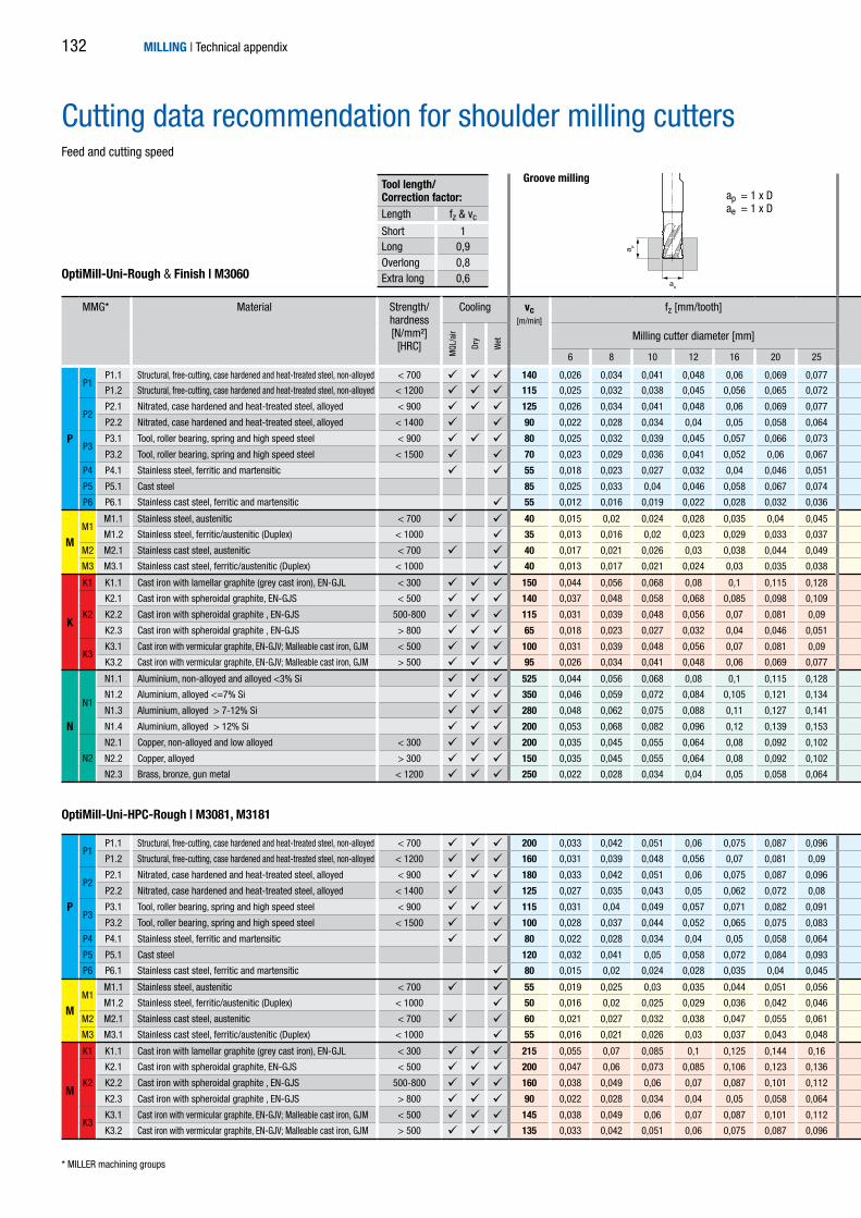
ae
a p
MMG* Material Strength/hardness [N/mm²]
[HRC]
Cooling vc[m/min]
fz [mm/tooth] vc[m/min]
fz [mm/tooth] vc[m/min]
fz [mm/tooth]
MQL
/air
Dry
Wet Milling cutter diameter [mm] Milling cutter diameter [mm] Milling cutter diameter [mm]
6 8 10 12 16 20 25 6 8 10 12 16 20 25 6 8 10 12 16 20 25
P
P1P1.1 Structural, free-cutting, case hardened and heat-treated steel, non-alloyed < 700 140 0,026 0,034 0,041 0,048 0,06 0,069 0,077 285 0,045 0,057 0,07 0,081 0,101 0,118 0,13 415 0,07 0,091 0,11 0,128 0,16 0,186 0,206
P1.2 Structural, free-cutting, case hardened and heat-treated steel, non-alloyed < 1200 115 0,025 0,032 0,038 0,045 0,056 0,065 0,072 230 0,042 0,054 0,065 0,076 0,095 0,11 0,122 340 0,066 0,085 0,103 0,12 0,15 0,173 0,192
P2P2.1 Nitrated, case hardened and heat-treated steel, alloyed < 900 125 0,026 0,034 0,041 0,048 0,06 0,069 0,077 260 0,045 0,057 0,07 0,081 0,101 0,118 0,13 380 0,07 0,091 0,11 0,128 0,16 0,186 0,206
P2.2 Nitrated, case hardened and heat-treated steel, alloyed < 1400 90 0,022 0,028 0,034 0,04 0,05 0,058 0,064 180 0,037 0,048 0,058 0,068 0,085 0,098 0,108 265 0,059 0,076 0,092 0,107 0,134 0,155 0,172
P3P3.1 Tool, roller bearing, spring and high speed steel < 900 80 0,025 0,032 0,039 0,045 0,057 0,066 0,073 165 0,042 0,054 0,066 0,077 0,096 0,112 0,124 245 0,067 0,086 0,104 0,122 0,152 0,177 0,196
P3.2 Tool, roller bearing, spring and high speed steel < 1500 70 0,023 0,029 0,036 0,041 0,052 0,06 0,067 140 0,039 0,05 0,06 0,07 0,088 0,102 0,113 210 0,061 0,079 0,095 0,111 0,139 0,161 0,178
P4 P4.1 Stainless steel, ferritic and martensitic 55 0,018 0,023 0,027 0,032 0,04 0,046 0,051 115 0,03 0,038 0,046 0,054 0,068 0,078 0,087 170 0,047 0,06 0,073 0,085 0,107 0,124 0,137
P5 P5.1 Cast steel 85 0,025 0,033 0,04 0,046 0,058 0,067 0,074 175 0,043 0,055 0,067 0,078 0,098 0,114 0,126 255 0,068 0,088 0,106 0,124 0,155 0,18 0,199
P6 P6.1 Stainless cast steel, ferritic and martensitic 55 0,012 0,016 0,019 0,022 0,028 0,032 0,036 115 0,021 0,027 0,032 0,038 0,047 0,055 0,061 170 0,033 0,042 0,051 0,06 0,075 0,087 0,096
MM1
M1.1 Stainless steel, austenitic < 700 40 0,015 0,02 0,024 0,028 0,035 0,04 0,045 75 0,026 0,033 0,041 0,047 0,059 0,069 0,076 115 0,041 0,053 0,064 0,075 0,094 0,108 0,12
M1.2 Stainless steel, ferritic/austenitic (Duplex) < 1000 35 0,013 0,016 0,02 0,023 0,029 0,033 0,037 70 0,022 0,028 0,034 0,039 0,049 0,057 0,063 105 0,034 0,044 0,053 0,062 0,077 0,09 0,099
M2 M2.1 Stainless cast steel, austenitic < 700 40 0,017 0,021 0,026 0,03 0,038 0,044 0,049 85 0,028 0,036 0,044 0,051 0,064 0,074 0,082 125 0,045 0,057 0,07 0,081 0,102 0,118 0,13
M3 M3.1 Stainless cast steel, ferritic/austenitic (Duplex) < 1000 40 0,013 0,017 0,021 0,024 0,03 0,035 0,038 75 0,022 0,029 0,035 0,041 0,051 0,059 0,065 115 0,035 0,045 0,055 0,064 0,08 0,093 0,103
K
K1 K1.1 Cast iron with lamellar graphite (grey cast iron), EN-GJL < 300 150 0,044 0,056 0,068 0,08 0,1 0,115 0,128 310 0,074 0,096 0,116 0,135 0,169 0,196 0,217 455 0,117 0,151 0,183 0,214 0,267 0,31 0,343
K2
K2.1 Cast iron with spheroidal graphite, EN-GJS < 500 140 0,037 0,048 0,058 0,068 0,085 0,098 0,109 285 0,063 0,081 0,099 0,115 0,144 0,166 0,184 415 0,1 0,128 0,156 0,182 0,227 0,263 0,292
K2.2 Cast iron with spheroidal graphite , EN-GJS 500-800 115 0,031 0,039 0,048 0,056 0,07 0,081 0,09 230 0,052 0,067 0,081 0,095 0,118 0,137 0,152 340 0,082 0,106 0,128 0,149 0,187 0,217 0,24
K2.3 Cast iron with spheroidal graphite , EN-GJS > 800 65 0,018 0,023 0,027 0,032 0,04 0,046 0,051 130 0,03 0,038 0,046 0,054 0,068 0,078 0,087 190 0,047 0,06 0,073 0,085 0,107 0,124 0,137
K3K3.1 Cast iron with vermicular graphite, EN-GJV; Malleable cast iron, GJM < 500 100 0,031 0,039 0,048 0,056 0,07 0,081 0,09 205 0,052 0,067 0,081 0,095 0,118 0,137 0,152 300 0,082 0,106 0,128 0,149 0,187 0,217 0,24
K3.2 Cast iron with vermicular graphite, EN-GJV; Malleable cast iron, GJM > 500 95 0,026 0,034 0,041 0,048 0,06 0,069 0,077 195 0,045 0,057 0,07 0,081 0,101 0,118 0,13 285 0,07 0,091 0,11 0,128 0,16 0,186 0,206
N
N1
N1.1 Aluminium, non-alloyed and alloyed <3% Si 525 0,044 0,056 0,068 0,08 0,1 0,115 0,128 1075 0,074 0,096 0,116 0,135 0,169 0,196 0,217 1580 0,117 0,151 0,183 0,214 0,267 0,31 0,343
N1.2 Aluminium, alloyed <=7% Si 350 0,046 0,059 0,072 0,084 0,105 0,121 0,134 715 0,078 0,1 0,122 0,142 0,177 0,206 0,228 1050 0,123 0,159 0,192 0,224 0,281 0,325 0,36
N1.3 Aluminium, alloyed > 7-12% Si 280 0,048 0,062 0,075 0,088 0,11 0,127 0,141 570 0,082 0,105 0,128 0,149 0,186 0,215 0,239 840 0,129 0,166 0,202 0,235 0,294 0,341 0,377
N1.4 Aluminium, alloyed > 12% Si 200 0,053 0,068 0,082 0,096 0,12 0,139 0,153 410 0,089 0,115 0,139 0,162 0,203 0,235 0,26 605 0,141 0,181 0,22 0,256 0,321 0,372 0,412
N2
N2.1 Copper, non-alloyed and low alloyed < 300 200 0,035 0,045 0,055 0,064 0,08 0,092 0,102 410 0,059 0,076 0,093 0,108 0,135 0,157 0,174 605 0,094 0,121 0,147 0,171 0,214 0,248 0,274
N2.2 Copper, alloyed > 300 150 0,035 0,045 0,055 0,064 0,08 0,092 0,102 310 0,059 0,076 0,093 0,108 0,135 0,157 0,174 455 0,094 0,121 0,147 0,171 0,214 0,248 0,274
N2.3 Brass, bronze, gun metal < 1200 250 0,022 0,028 0,034 0,04 0,05 0,058 0,064 515 0,037 0,048 0,058 0,068 0,085 0,098 0,108 755 0,059 0,076 0,092 0,107 0,134 0,155 0,172
P
P1P1.1 Structural, free-cutting, case hardened and heat-treated steel, non-alloyed < 700 200 0,033 0,042 0,051 0,06 0,075 0,087 0,096 405 0,056 0,072 0,087 0,101 0,127 0,147 0,163
P1.2 Structural, free-cutting, case hardened and heat-treated steel, non-alloyed < 1200 160 0,031 0,039 0,048 0,056 0,07 0,081 0,09 330 0,052 0,067 0,081 0,095 0,118 0,137 0,152
P2P2.1 Nitrated, case hardened and heat-treated steel, alloyed < 900 180 0,033 0,042 0,051 0,06 0,075 0,087 0,096 370 0,056 0,072 0,087 0,101 0,127 0,147 0,163
P2.2 Nitrated, case hardened and heat-treated steel, alloyed < 1400 125 0,027 0,035 0,043 0,05 0,062 0,072 0,08 260 0,046 0,06 0,072 0,084 0,106 0,122 0,136
P3P3.1 Tool, roller bearing, spring and high speed steel < 900 115 0,031 0,04 0,049 0,057 0,071 0,082 0,091 240 0,053 0,068 0,083 0,096 0,12 0,14 0,155
P3.2 Tool, roller bearing, spring and high speed steel < 1500 100 0,028 0,037 0,044 0,052 0,065 0,075 0,083 200 0,048 0,062 0,075 0,088 0,11 0,127 0,141
P4 P4.1 Stainless steel, ferritic and martensitic 80 0,022 0,028 0,034 0,04 0,05 0,058 0,064 165 0,037 0,048 0,058 0,068 0,085 0,098 0,108
P5 P5.1 Cast steel 120 0,032 0,041 0,05 0,058 0,072 0,084 0,093 245 0,054 0,069 0,084 0,098 0,123 0,142 0,157
P6 P6.1 Stainless cast steel, ferritic and martensitic 80 0,015 0,02 0,024 0,028 0,035 0,04 0,045 165 0,026 0,033 0,041 0,047 0,059 0,069 0,076
MM1
M1.1 Stainless steel, austenitic < 700 55 0,019 0,025 0,03 0,035 0,044 0,051 0,056 110 0,033 0,042 0,051 0,059 0,074 0,086 0,095
M1.2 Stainless steel, ferritic/austenitic (Duplex) < 1000 50 0,016 0,02 0,025 0,029 0,036 0,042 0,046 105 0,027 0,035 0,042 0,049 0,061 0,071 0,079
M2 M2.1 Stainless cast steel, austenitic < 700 60 0,021 0,027 0,032 0,038 0,047 0,055 0,061 120 0,035 0,045 0,055 0,064 0,08 0,093 0,103
M3 M3.1 Stainless cast steel, ferritic/austenitic (Duplex) < 1000 55 0,016 0,021 0,026 0,03 0,037 0,043 0,048 110 0,028 0,036 0,043 0,051 0,063 0,073 0,081
M
K1 K1.1 Cast iron with lamellar graphite (grey cast iron), EN-GJL < 300 215 0,055 0,07 0,085 0,1 0,125 0,144 0,16 440 0,093 0,119 0,145 0,169 0,211 0,245 0,271
K2
K2.1 Cast iron with spheroidal graphite, EN-GJS < 500 200 0,047 0,06 0,073 0,085 0,106 0,123 0,136 405 0,079 0,102 0,123 0,144 0,18 0,208 0,231
K2.2 Cast iron with spheroidal graphite , EN-GJS 500-800 160 0,038 0,049 0,06 0,07 0,087 0,101 0,112 330 0,065 0,084 0,101 0,118 0,148 0,171 0,19
K2.3 Cast iron with spheroidal graphite , EN-GJS > 800 90 0,022 0,028 0,034 0,04 0,05 0,058 0,064 185 0,037 0,048 0,058 0,068 0,085 0,098 0,108
K3K3.1 Cast iron with vermicular graphite, EN-GJV; Malleable cast iron, GJM < 500 145 0,038 0,049 0,06 0,07 0,087 0,101 0,112 295 0,065 0,084 0,101 0,118 0,148 0,171 0,19
K3.2 Cast iron with vermicular graphite, EN-GJV; Malleable cast iron, GJM > 500 135 0,033 0,042 0,051 0,06 0,075 0,087 0,096 275 0,056 0,072 0,087 0,101 0,127 0,147 0,163
OptiMill-Uni-Rough & Finish | M3060
OptiMill-Uni-HPC-Rough | M3081, M3181
* MILLER machining groups
ap = 1 x Dae = 1 x D
Groove milling
MILLING | Technical appendix
Tool length/ Correction factor:Length fz & vc
Short 1Long 0,9Overlong 0,8Extra long 0,6
Cutting data recommendation for shoulder milling cuttersFeed and cutting speed
132

ae
a p
ae
a p
MMG* Material Strength/hardness [N/mm²]
[HRC]
Cooling vc[m/min]
fz [mm/tooth] vc[m/min]
fz [mm/tooth] vc[m/min]
fz [mm/tooth]
MQL
/air
Dry
Wet Milling cutter diameter [mm] Milling cutter diameter [mm] Milling cutter diameter [mm]
6 8 10 12 16 20 25 6 8 10 12 16 20 25 6 8 10 12 16 20 25
P
P1P1.1 Structural, free-cutting, case hardened and heat-treated steel, non-alloyed < 700 140 0,026 0,034 0,041 0,048 0,06 0,069 0,077 285 0,045 0,057 0,07 0,081 0,101 0,118 0,13 415 0,07 0,091 0,11 0,128 0,16 0,186 0,206
P1.2 Structural, free-cutting, case hardened and heat-treated steel, non-alloyed < 1200 115 0,025 0,032 0,038 0,045 0,056 0,065 0,072 230 0,042 0,054 0,065 0,076 0,095 0,11 0,122 340 0,066 0,085 0,103 0,12 0,15 0,173 0,192
P2P2.1 Nitrated, case hardened and heat-treated steel, alloyed < 900 125 0,026 0,034 0,041 0,048 0,06 0,069 0,077 260 0,045 0,057 0,07 0,081 0,101 0,118 0,13 380 0,07 0,091 0,11 0,128 0,16 0,186 0,206
P2.2 Nitrated, case hardened and heat-treated steel, alloyed < 1400 90 0,022 0,028 0,034 0,04 0,05 0,058 0,064 180 0,037 0,048 0,058 0,068 0,085 0,098 0,108 265 0,059 0,076 0,092 0,107 0,134 0,155 0,172
P3P3.1 Tool, roller bearing, spring and high speed steel < 900 80 0,025 0,032 0,039 0,045 0,057 0,066 0,073 165 0,042 0,054 0,066 0,077 0,096 0,112 0,124 245 0,067 0,086 0,104 0,122 0,152 0,177 0,196
P3.2 Tool, roller bearing, spring and high speed steel < 1500 70 0,023 0,029 0,036 0,041 0,052 0,06 0,067 140 0,039 0,05 0,06 0,07 0,088 0,102 0,113 210 0,061 0,079 0,095 0,111 0,139 0,161 0,178
P4 P4.1 Stainless steel, ferritic and martensitic 55 0,018 0,023 0,027 0,032 0,04 0,046 0,051 115 0,03 0,038 0,046 0,054 0,068 0,078 0,087 170 0,047 0,06 0,073 0,085 0,107 0,124 0,137
P5 P5.1 Cast steel 85 0,025 0,033 0,04 0,046 0,058 0,067 0,074 175 0,043 0,055 0,067 0,078 0,098 0,114 0,126 255 0,068 0,088 0,106 0,124 0,155 0,18 0,199
P6 P6.1 Stainless cast steel, ferritic and martensitic 55 0,012 0,016 0,019 0,022 0,028 0,032 0,036 115 0,021 0,027 0,032 0,038 0,047 0,055 0,061 170 0,033 0,042 0,051 0,06 0,075 0,087 0,096
MM1
M1.1 Stainless steel, austenitic < 700 40 0,015 0,02 0,024 0,028 0,035 0,04 0,045 75 0,026 0,033 0,041 0,047 0,059 0,069 0,076 115 0,041 0,053 0,064 0,075 0,094 0,108 0,12
M1.2 Stainless steel, ferritic/austenitic (Duplex) < 1000 35 0,013 0,016 0,02 0,023 0,029 0,033 0,037 70 0,022 0,028 0,034 0,039 0,049 0,057 0,063 105 0,034 0,044 0,053 0,062 0,077 0,09 0,099
M2 M2.1 Stainless cast steel, austenitic < 700 40 0,017 0,021 0,026 0,03 0,038 0,044 0,049 85 0,028 0,036 0,044 0,051 0,064 0,074 0,082 125 0,045 0,057 0,07 0,081 0,102 0,118 0,13
M3 M3.1 Stainless cast steel, ferritic/austenitic (Duplex) < 1000 40 0,013 0,017 0,021 0,024 0,03 0,035 0,038 75 0,022 0,029 0,035 0,041 0,051 0,059 0,065 115 0,035 0,045 0,055 0,064 0,08 0,093 0,103
K
K1 K1.1 Cast iron with lamellar graphite (grey cast iron), EN-GJL < 300 150 0,044 0,056 0,068 0,08 0,1 0,115 0,128 310 0,074 0,096 0,116 0,135 0,169 0,196 0,217 455 0,117 0,151 0,183 0,214 0,267 0,31 0,343
K2
K2.1 Cast iron with spheroidal graphite, EN-GJS < 500 140 0,037 0,048 0,058 0,068 0,085 0,098 0,109 285 0,063 0,081 0,099 0,115 0,144 0,166 0,184 415 0,1 0,128 0,156 0,182 0,227 0,263 0,292
K2.2 Cast iron with spheroidal graphite , EN-GJS 500-800 115 0,031 0,039 0,048 0,056 0,07 0,081 0,09 230 0,052 0,067 0,081 0,095 0,118 0,137 0,152 340 0,082 0,106 0,128 0,149 0,187 0,217 0,24
K2.3 Cast iron with spheroidal graphite , EN-GJS > 800 65 0,018 0,023 0,027 0,032 0,04 0,046 0,051 130 0,03 0,038 0,046 0,054 0,068 0,078 0,087 190 0,047 0,06 0,073 0,085 0,107 0,124 0,137
K3K3.1 Cast iron with vermicular graphite, EN-GJV; Malleable cast iron, GJM < 500 100 0,031 0,039 0,048 0,056 0,07 0,081 0,09 205 0,052 0,067 0,081 0,095 0,118 0,137 0,152 300 0,082 0,106 0,128 0,149 0,187 0,217 0,24
K3.2 Cast iron with vermicular graphite, EN-GJV; Malleable cast iron, GJM > 500 95 0,026 0,034 0,041 0,048 0,06 0,069 0,077 195 0,045 0,057 0,07 0,081 0,101 0,118 0,13 285 0,07 0,091 0,11 0,128 0,16 0,186 0,206
N
N1
N1.1 Aluminium, non-alloyed and alloyed <3% Si 525 0,044 0,056 0,068 0,08 0,1 0,115 0,128 1075 0,074 0,096 0,116 0,135 0,169 0,196 0,217 1580 0,117 0,151 0,183 0,214 0,267 0,31 0,343
N1.2 Aluminium, alloyed <=7% Si 350 0,046 0,059 0,072 0,084 0,105 0,121 0,134 715 0,078 0,1 0,122 0,142 0,177 0,206 0,228 1050 0,123 0,159 0,192 0,224 0,281 0,325 0,36
N1.3 Aluminium, alloyed > 7-12% Si 280 0,048 0,062 0,075 0,088 0,11 0,127 0,141 570 0,082 0,105 0,128 0,149 0,186 0,215 0,239 840 0,129 0,166 0,202 0,235 0,294 0,341 0,377
N1.4 Aluminium, alloyed > 12% Si 200 0,053 0,068 0,082 0,096 0,12 0,139 0,153 410 0,089 0,115 0,139 0,162 0,203 0,235 0,26 605 0,141 0,181 0,22 0,256 0,321 0,372 0,412
N2
N2.1 Copper, non-alloyed and low alloyed < 300 200 0,035 0,045 0,055 0,064 0,08 0,092 0,102 410 0,059 0,076 0,093 0,108 0,135 0,157 0,174 605 0,094 0,121 0,147 0,171 0,214 0,248 0,274
N2.2 Copper, alloyed > 300 150 0,035 0,045 0,055 0,064 0,08 0,092 0,102 310 0,059 0,076 0,093 0,108 0,135 0,157 0,174 455 0,094 0,121 0,147 0,171 0,214 0,248 0,274
N2.3 Brass, bronze, gun metal < 1200 250 0,022 0,028 0,034 0,04 0,05 0,058 0,064 515 0,037 0,048 0,058 0,068 0,085 0,098 0,108 755 0,059 0,076 0,092 0,107 0,134 0,155 0,172
P
P1P1.1 Structural, free-cutting, case hardened and heat-treated steel, non-alloyed < 700 200 0,033 0,042 0,051 0,06 0,075 0,087 0,096 405 0,056 0,072 0,087 0,101 0,127 0,147 0,163
P1.2 Structural, free-cutting, case hardened and heat-treated steel, non-alloyed < 1200 160 0,031 0,039 0,048 0,056 0,07 0,081 0,09 330 0,052 0,067 0,081 0,095 0,118 0,137 0,152
P2P2.1 Nitrated, case hardened and heat-treated steel, alloyed < 900 180 0,033 0,042 0,051 0,06 0,075 0,087 0,096 370 0,056 0,072 0,087 0,101 0,127 0,147 0,163
P2.2 Nitrated, case hardened and heat-treated steel, alloyed < 1400 125 0,027 0,035 0,043 0,05 0,062 0,072 0,08 260 0,046 0,06 0,072 0,084 0,106 0,122 0,136
P3P3.1 Tool, roller bearing, spring and high speed steel < 900 115 0,031 0,04 0,049 0,057 0,071 0,082 0,091 240 0,053 0,068 0,083 0,096 0,12 0,14 0,155
P3.2 Tool, roller bearing, spring and high speed steel < 1500 100 0,028 0,037 0,044 0,052 0,065 0,075 0,083 200 0,048 0,062 0,075 0,088 0,11 0,127 0,141
P4 P4.1 Stainless steel, ferritic and martensitic 80 0,022 0,028 0,034 0,04 0,05 0,058 0,064 165 0,037 0,048 0,058 0,068 0,085 0,098 0,108
P5 P5.1 Cast steel 120 0,032 0,041 0,05 0,058 0,072 0,084 0,093 245 0,054 0,069 0,084 0,098 0,123 0,142 0,157
P6 P6.1 Stainless cast steel, ferritic and martensitic 80 0,015 0,02 0,024 0,028 0,035 0,04 0,045 165 0,026 0,033 0,041 0,047 0,059 0,069 0,076
MM1
M1.1 Stainless steel, austenitic < 700 55 0,019 0,025 0,03 0,035 0,044 0,051 0,056 110 0,033 0,042 0,051 0,059 0,074 0,086 0,095
M1.2 Stainless steel, ferritic/austenitic (Duplex) < 1000 50 0,016 0,02 0,025 0,029 0,036 0,042 0,046 105 0,027 0,035 0,042 0,049 0,061 0,071 0,079
M2 M2.1 Stainless cast steel, austenitic < 700 60 0,021 0,027 0,032 0,038 0,047 0,055 0,061 120 0,035 0,045 0,055 0,064 0,08 0,093 0,103
M3 M3.1 Stainless cast steel, ferritic/austenitic (Duplex) < 1000 55 0,016 0,021 0,026 0,03 0,037 0,043 0,048 110 0,028 0,036 0,043 0,051 0,063 0,073 0,081
M
K1 K1.1 Cast iron with lamellar graphite (grey cast iron), EN-GJL < 300 215 0,055 0,07 0,085 0,1 0,125 0,144 0,16 440 0,093 0,119 0,145 0,169 0,211 0,245 0,271
K2
K2.1 Cast iron with spheroidal graphite, EN-GJS < 500 200 0,047 0,06 0,073 0,085 0,106 0,123 0,136 405 0,079 0,102 0,123 0,144 0,18 0,208 0,231
K2.2 Cast iron with spheroidal graphite , EN-GJS 500-800 160 0,038 0,049 0,06 0,07 0,087 0,101 0,112 330 0,065 0,084 0,101 0,118 0,148 0,171 0,19
K2.3 Cast iron with spheroidal graphite , EN-GJS > 800 90 0,022 0,028 0,034 0,04 0,05 0,058 0,064 185 0,037 0,048 0,058 0,068 0,085 0,098 0,108
K3K3.1 Cast iron with vermicular graphite, EN-GJV; Malleable cast iron, GJM < 500 145 0,038 0,049 0,06 0,07 0,087 0,101 0,112 295 0,065 0,084 0,101 0,118 0,148 0,171 0,19
K3.2 Cast iron with vermicular graphite, EN-GJV; Malleable cast iron, GJM > 500 135 0,033 0,042 0,051 0,06 0,075 0,087 0,096 275 0,056 0,072 0,087 0,101 0,127 0,147 0,163
ap = 1,5 x Dae = 0,25 x D
ap = 1,5 x Dae = 0,1 x D
Roughing Finishing
MILLING | Technical appendix 133

ae
a p
ae
a p
Cutting data recommendation for shoulder milling cuttersFeed and cutting speed
MMG* Material Strength/hardness [N/mm²]
[HRC]
Cooling vc[m/min]
fz [mm/tooth]
MQL
/air
Dry
Wet Milling cutter diameter [mm]
4 6 8 10 12 16 20 25
P
P1P1.1 Structural, free-cutting, case hardened and heat-treated steel, non-alloyed < 700 415 0,05 0,07 0,091 0,11 0,128 0,16 0,186 0,206
P1.2 Structural, free-cutting, case hardened and heat-treated steel, non-alloyed < 1200 340 0,046 0,066 0,085 0,103 0,12 0,15 0,173 0,192
P2P2.1 Nitrated, case hardened and heat-treated steel, alloyed < 900 380 0,05 0,07 0,091 0,11 0,128 0,16 0,186 0,206
P2.2 Nitrated, case hardened and heat-treated steel, alloyed < 1400 265 0,041 0,059 0,076 0,092 0,107 0,134 0,155 0,172
P3P3.1 Tool, roller bearing, spring and high speed steel < 900 245 0,047 0,067 0,086 0,104 0,122 0,152 0,177 0,196
P3.2 Tool, roller bearing, spring and high speed steel < 1500 210 0,043 0,061 0,079 0,095 0,111 0,139 0,161 0,178
P4 P4.1 Stainless steel, ferritic and martensitic 170 0,033 0,047 0,06 0,073 0,085 0,107 0,124 0,137
P5 P5.1 Cast steel 255 0,048 0,068 0,088 0,106 0,124 0,155 0,18 0,199
P6 P6.1 Stainless cast steel, ferritic and martensitic 170 0,023 0,033 0,042 0,051 0,06 0,075 0,087 0,096
M
M1M1.1 Stainless steel, austenitic < 700 115 0,029 0,041 0,053 0,064 0,075 0,094 0,108 0,12
M1.2 Stainless steel, ferritic/austenitic (Duplex) < 1000 105 0,024 0,034 0,044 0,053 0,062 0,077 0,09 0,099
M2 M2.1 Stainless cast steel, austenitic < 700 125 0,031 0,045 0,057 0,07 0,081 0,102 0,118 0,13
M3 M3.1 Stainless cast steel, ferritic/austenitic (Duplex) < 1000 115 0,025 0,035 0,045 0,055 0,064 0,08 0,093 0,103
K
K1 K1.1 Cast iron with lamellar graphite (grey cast iron), EN-GJL < 300 455 0,083 0,117 0,151 0,183 0,214 0,267 0,31 0,343
K2
K2.1 Cast iron with spheroidal graphite, EN-GJS < 500 415 0,07 0,1 0,128 0,156 0,182 0,227 0,263 0,292
K2.2 Cast iron with spheroidal graphite , EN-GJS 500-800 340 0,058 0,082 0,106 0,128 0,149 0,187 0,217 0,24
K2.3 Cast iron with spheroidal graphite , EN-GJS > 800 190 0,033 0,047 0,06 0,073 0,085 0,107 0,124 0,137
K3K3.1 Cast iron with vermicular graphite, EN-GJV; Malleable cast iron, GJM < 500 300 0,058 0,082 0,106 0,128 0,149 0,187 0,217 0,24
K3.2 Cast iron with vermicular graphite, EN-GJV; Malleable cast iron, GJM > 500 285 0,05 0,07 0,091 0,11 0,128 0,16 0,186 0,206
HH1
H1.1 Hardened steel/cast steel 45-55 115 0,021 0,029 0,038 0,046 0,053 0,067 0,077
H1.2 Hardened steel/cast steel 55-64 55 0,015 0,022 0,028 0,034 0,04 0,05 0,058
H2 H2.1 Wear resistant castings/chilled cast iron, GJN 55 0,015 0,022 0,028 0,034 0,04 0,05 0,058
OptiMill-Uni-Finish | M3046, M3048, M3049
OptiMill-Hardened | M3076, M3078, M3071
* MILLER machining groups
ap = 1,5 x Dae = 0,1 x D
Finishing
MILLING | Technical appendix
MMG* Material Strength/hardness [N/mm²]
[HRC]
Cooling vc[m/min]
fz [mm/tooth] vc[m/min]
fz [mm/tooth]
MQL
/air
Dry
Wet Milling cutter diameter [mm] Milling cutter diameter [mm]
6 8 10 12 16 20 25 32 6 8 10 12 16 20 25 32
N N1
N1.1 Aluminium, non-alloyed and alloyed <3% Si 1955 0,103 0,133 0,161 0,188 0,235 0,273 0,302 0,303 1955 0,119 0,153 0,186 0,217 0,271 0,314 0,348 0,349
N1.2 Aluminium, alloyed <=7% Si 1300 0,109 0,140 0,169 0,197 0,247 0,286 0,317 0,318 1300 0,125 0,161 0,195 0,227 0,285 0,330 0,365 0,367
N1.3 Aluminium, alloyed > 7-12% Si 1040 0,114 0,146 0,178 0,207 0,259 0,300 0,332 0,334 1040 0,131 0,169 0,204 0,238 0,298 0,345 0,383 0,384
N1.4 Aluminium, alloyed > 12% Si 750 0,124 0,160 0,194 0,226 0,282 0,327 0,362 0,364 750 0,143 0,184 0,223 0,260 0,325 0,377 0,418 0,419
OptiMill-Volume-N | M3591, M3593
ap = 0,5 x Dae = 1 x D
Groove millingTool length/ Correction factor:Length fz & vc
Short 1Long 0,9Overlong 0,8Extra long 0,6
Cutting data recommendation for shoulder milling cuttersFeed and cutting speed
134

ae
a p
ae
a p
MMG* Material Strength/hardness [N/mm²]
[HRC]
Cooling vc[m/min]
fz [mm/tooth] **
MQL
/air
Dry
Wet Milling cutter diameter [mm]
4 6 8 10 12 16 20 25
P
P1P1.1 Structural, free-cutting, case hardened and heat-treated steel, non-alloyed < 700 595 0,062 0,035 0,062 0,088 0,113 0,137 0,16 0,257
P1.2 Structural, free-cutting, case hardened and heat-treated steel, non-alloyed < 1200 485 0,058 0,033 0,058 0,082 0,106 0,128 0,149 0,24
P2P2.1 Nitrated, case hardened and heat-treated steel, alloyed < 900 540 0,062 0,035 0,062 0,088 0,113 0,137 0,16 0,257
P2.2 Nitrated, case hardened and heat-treated steel, alloyed < 1400 380 0,052 0,029 0,052 0,073 0,094 0,115 0,133 0,214
P3P3.1 Tool, roller bearing, spring and high speed steel < 900 350 0,059 0,033 0,059 0,084 0,108 0,131 0,152 0,244
P3.2 Tool, roller bearing, spring and high speed steel < 1500 295 0,054 0,03 0,054 0,076 0,098 0,119 0,139 0,223
P4 P4.1 Stainless steel, ferritic and martensitic 245 0,041 0,023 0,041 0,059 0,076 0,092 0,107 0,172
P5 P5.1 Cast steel 360 0,06 0,034 0,06 0,085 0,11 0,133 0,155 0,249
P6 P6.1 Stainless cast steel, ferritic and martensitic 245 0,029 0,016 0,029 0,041 0,053 0,064 0,075 0,12
M
M1M1.1 Stainless steel, austenitic < 700 160 0,036 0,02 0,036 0,051 0,066 0,08 0,093 0,15
M1.2 Stainless steel, ferritic/austenitic (Duplex) < 1000 150 0,03 0,017 0,03 0,043 0,055 0,066 0,077 0,124
M2 M2.1 Stainless cast steel, austenitic < 700 180 0,039 0,022 0,039 0,056 0,072 0,087 0,101 0,163
M3 M3.1 Stainless cast steel, ferritic/austenitic (Duplex) < 1000 160 0,031 0,017 0,031 0,044 0,057 0,069 0,08 0,129
K
K1 K1.1 Cast iron with lamellar graphite (grey cast iron), EN-GJL < 300 650 0,103 0,058 0,103 0,147 0,189 0,229 0,267 0,429
K2
K2.1 Cast iron with spheroidal graphite, EN-GJS < 500 595 0,088 0,05 0,088 0,125 0,161 0,195 0,227 0,365
K2.2 Cast iron with spheroidal graphite , EN-GJS 500-800 485 0,072 0,041 0,072 0,103 0,132 0,16 0,187 0,3
K2.3 Cast iron with spheroidal graphite , EN-GJS > 800 270 0,041 0,023 0,041 0,059 0,076 0,092 0,107 0,172
K3K3.1 Cast iron with vermicular graphite, EN-GJV; Malleable cast iron, GJM < 500 430 0,072 0,041 0,072 0,103 0,132 0,16 0,187 0,3
K3.2 Cast iron with vermicular graphite, EN-GJV; Malleable cast iron, GJM > 500 405 0,062 0,035 0,062 0,088 0,113 0,137 0,16 0,257
OptiMill-Uni-HPC-Finish | M3096
* MILLER machining groups
** To achieve better surface finishes, the feed rates must be appropriately reduced. E.g.: finishing with SCM37, ø 20 mm of 42CrMo4, ae = 0.2 mm (synchronous milling)
Standard values: 42CrMo4 vc = 200 m/min. fz = 0,1 mm Ra = 1,00 Rz = 5 Modified values: 42CrMo4 vc = 200 m/min. fz = 0,03 mm Ra = 0,30 Rz = 1
ap = 1,5 x Dae = 0,1 x D
Finishing
MILLING | Technical appendix
MMG* Material Strength/hardness [N/mm²]
[HRC]
Cooling vc[m/min]
fz [mm/tooth] vc[m/min]
fz [mm/tooth]
MQL
/air
Dry
Wet Milling cutter diameter [mm] Milling cutter diameter [mm]
6 8 10 12 16 20 25 32 6 8 10 12 16 20 25 32
N N1
N1.1 Aluminium, non-alloyed and alloyed <3% Si 1955 0,103 0,133 0,161 0,188 0,235 0,273 0,302 0,303 1955 0,119 0,153 0,186 0,217 0,271 0,314 0,348 0,349
N1.2 Aluminium, alloyed <=7% Si 1300 0,109 0,140 0,169 0,197 0,247 0,286 0,317 0,318 1300 0,125 0,161 0,195 0,227 0,285 0,330 0,365 0,367
N1.3 Aluminium, alloyed > 7-12% Si 1040 0,114 0,146 0,178 0,207 0,259 0,300 0,332 0,334 1040 0,131 0,169 0,204 0,238 0,298 0,345 0,383 0,384
N1.4 Aluminium, alloyed > 12% Si 750 0,124 0,160 0,194 0,226 0,282 0,327 0,362 0,364 750 0,143 0,184 0,223 0,260 0,325 0,377 0,418 0,419
ap = 0,3 x Dae = 1 x D
Groove milling
135

ae
a p
OptiMill-Tro-Uni | M3099OptiMill-Tro-PM | M3299
OptiMill-Tro-S | M3699, OptiMill-Tro-Titan | M3799
* MILLER machining groups
ap = max. 3 x Dae = depends on material
MILLING | Technical appendix
OptiMill-Tro-H | M3079
Cutting data recommendation for trochoidal milling cuttersFeed and cutting speed
MMG* Material Strength/hardness [N/mm²]
[HRC]
Cooling vc[m/min]
fz [mm/tooth] in % from D
ae [mm] in % from D
hm [mm] in % from D
Machining example
MQL
/air
Dry
Wet
P
P1P1.1 Structural, free-cutting, case hardened and heat-treated steel, non-alloyed < 700 380-520 2,0-2,6 14-18 0,66-0,8 16MnCr5 ø = 12 mm
vc = 500 m/min fz = 0,28 mm ae = 1,8 mm ap = 32 mm
42CrMo4 ø = 12 mm vc = 375 m/min fz = 0,17 mm ae = 1,2 mm ap = 32 mm
P1.2 Structural, free-cutting, case hardened and heat-treated steel, non-alloyed < 1200 320-460 1,8-2,4 12-16 0,62-0,76
P2P2.1 Nitrated, case hardened and heat-treated steel, alloyed < 900 340-480 1,8-2,4 10-14 0,58-0,71
P2.2 Nitrated, case hardened and heat-treated steel, alloyed < 1400 280-380 1,4-2,0 8-12 0,56-0,68
P3P3.1 Tool, roller bearing, spring and high speed steel < 900 240-350 1,5-2,2 8-14 0,54-0,65
P3.2 Tool, roller bearing, spring and high speed steel < 1500 210-320 1,2-1,9 6-12 0,52-0,62
P4 P4.1 Stainless steel, ferritic and martensitic 180-260 1,0-1,8 6-12 0,5-0,6
P5 P5.1 Cast steel 220-300 1,4-2,0 8-12 0,54-0,62
P6 P6.1 Stainless cast steel, ferritic and martensitic 160-240 0,8-1,6 6-12 0,5-0,6
M
M1M1.1 Stainless steel, austenitic < 700 140-220 0,6-1,0 5-10 0,48-0,6 X5CrNi18-8 ø = 12 mm
vc = 180 m/min fz = 0,09 mm ae = 1,2 mm ap = 32 mm
M1.2 Stainless steel, ferritic/austenitic (Duplex) < 1000 110-180 0,6-1,0 5-10 0,46-0,58
M2 M2.1 Stainless cast steel, austenitic < 700 130-200 0,8-1,2 6-12 0,52-0,6
M3 M3.1 Stainless cast steel, ferritic/austenitic (Duplex) < 1000 120-180 0,8-1,2 5-10 0,46-0,56
K
K1 K1.1 Cast iron with lamellar graphite (grey cast iron), EN-GJL < 300 400-500 2,0-2,6 15-20 0,64-0,78
K2
K2.1 Cast iron with spheroidal graphite, EN-GJS < 500 340-500 1,8-2,4 12-16 0,62-0,7
K2.2 Cast iron with spheroidal graphite , EN-GJS 500-800 300-440 1,6-2,2 10-14 0,58-0,68
K2.3 Cast iron with spheroidal graphite , EN-GJS > 800 180-260 1,4-2,0 8-12 0,56-0,68
K3K3.1 Cast iron with vermicular graphite, EN-GJV; Malleable cast iron, GJM < 500 280-360 1,6-2,2 10-16 0,6-0,68
K3.2 Cast iron with vermicular graphite, EN-GJV; Malleable cast iron, GJM > 500 210-340 1,4-2,0 10-16 0,58-0,66
M
M1M1.1 Stainless steel, austenitic < 700 140-220 0,6-1,0 5-10 0,48-0,6 X5CrNi18-8 ø = 12 mm
vc = 180 m/min fz = 0,09 mm ae = 1,2 mm ap = 32 mm
M1.2 Stainless steel, ferritic/austenitic (Duplex) < 1000 110-180 0,6-1,0 5-10 0,46-0,58
M2 M2.1 Stainless cast steel, austenitic < 700 130-200 0,8-1,2 6-12 0,52-0,6
M3 M3.1 Stainless cast steel, ferritic/austenitic (Duplex) < 1000 120-180 0,8-1,2 5-10 0,46-0,56
S
S1 S1.1 Titanium, titanium alloy < 400 110-170 0,65-1,3 6-12 0,52-0,6 TiAl6V4 ø = 12 mm vc = 140 m/min fz = 0,09 mm ae = 1,2 mm ap = 30 mm
S2S2.1 Titanium, titanium alloy < 1200 90-150 0,6-1,2 5-10 0,46-0,56
S2.2 Titanium, titanium alloy > 1200 70-130 0,4-1,0 5-10 0,42-0,54
S3S3.1 Nickel, non-alloyed and alloyed < 900 60-120 0,4-1,0 5-10 0,4-0,52
S3.2 Nickel, non-alloyed and alloyed > 900 50-100 0,3-0,9 5-10 0,4-0,52
S4 S4.1 Heat resistant super alloys, Ni, Co, and Fe based 35-90 0,3-0,8 4-8 0,38-0,46
S5 S5.1 Tungsten and molybdenum alloys 35-90 0,3-0,8 4-8 0,38-0,46
HH1
H1.1 Hardened steel/cast steel 45-55 80-140 0,45-0,65 7-12 0,42-0,52 90MnCrV8 ø = 12 mm vc = 110 m/min fz = 0,052 mm hm = 0,04 mm ae = 1 mm
H1.2 Hardened steel/cast steel 55-64 60-120 0,4-0,52 6-12 0,4-0,5
H1.3 Hardened steel/cast steel 64-70 50-100 0,3-0,5 5-10 0,38-0,46
H2 H2.1 Wear resistant castings/chilled cast iron, GJN 60-120 0,35-0,55 6-12 0,4-0,48
Trochoidal milling
Note:With trochoidal milling, the cutting conditions indicated change during the machining process. This is also dependent on the CAM software used and the machining position of the tool in the work-piece. Feed rate and contact width or contact angle change constantly during the machining process in order to achieve the most constant average chip thickness possible, depending on the con-tour.
136

MILLING | Technical appendix
MMG* Material Strength/hardness [N/mm²]
[HRC]
Cooling vc[m/min]
fz [mm/tooth] in % from D
ae [mm] in % from D
hm [mm] in % from D
Machining example
MQL
/air
Dry
Wet
P
P1P1.1 Structural, free-cutting, case hardened and heat-treated steel, non-alloyed < 700 380-520 2,0-2,6 14-18 0,66-0,8 16MnCr5 ø = 12 mm
vc = 500 m/min fz = 0,28 mm ae = 1,8 mm ap = 32 mm
42CrMo4 ø = 12 mm vc = 375 m/min fz = 0,17 mm ae = 1,2 mm ap = 32 mm
P1.2 Structural, free-cutting, case hardened and heat-treated steel, non-alloyed < 1200 320-460 1,8-2,4 12-16 0,62-0,76
P2P2.1 Nitrated, case hardened and heat-treated steel, alloyed < 900 340-480 1,8-2,4 10-14 0,58-0,71
P2.2 Nitrated, case hardened and heat-treated steel, alloyed < 1400 280-380 1,4-2,0 8-12 0,56-0,68
P3P3.1 Tool, roller bearing, spring and high speed steel < 900 240-350 1,5-2,2 8-14 0,54-0,65
P3.2 Tool, roller bearing, spring and high speed steel < 1500 210-320 1,2-1,9 6-12 0,52-0,62
P4 P4.1 Stainless steel, ferritic and martensitic 180-260 1,0-1,8 6-12 0,5-0,6
P5 P5.1 Cast steel 220-300 1,4-2,0 8-12 0,54-0,62
P6 P6.1 Stainless cast steel, ferritic and martensitic 160-240 0,8-1,6 6-12 0,5-0,6
M
M1M1.1 Stainless steel, austenitic < 700 140-220 0,6-1,0 5-10 0,48-0,6 X5CrNi18-8 ø = 12 mm
vc = 180 m/min fz = 0,09 mm ae = 1,2 mm ap = 32 mm
M1.2 Stainless steel, ferritic/austenitic (Duplex) < 1000 110-180 0,6-1,0 5-10 0,46-0,58
M2 M2.1 Stainless cast steel, austenitic < 700 130-200 0,8-1,2 6-12 0,52-0,6
M3 M3.1 Stainless cast steel, ferritic/austenitic (Duplex) < 1000 120-180 0,8-1,2 5-10 0,46-0,56
K
K1 K1.1 Cast iron with lamellar graphite (grey cast iron), EN-GJL < 300 400-500 2,0-2,6 15-20 0,64-0,78
K2
K2.1 Cast iron with spheroidal graphite, EN-GJS < 500 340-500 1,8-2,4 12-16 0,62-0,7
K2.2 Cast iron with spheroidal graphite , EN-GJS 500-800 300-440 1,6-2,2 10-14 0,58-0,68
K2.3 Cast iron with spheroidal graphite , EN-GJS > 800 180-260 1,4-2,0 8-12 0,56-0,68
K3K3.1 Cast iron with vermicular graphite, EN-GJV; Malleable cast iron, GJM < 500 280-360 1,6-2,2 10-16 0,6-0,68
K3.2 Cast iron with vermicular graphite, EN-GJV; Malleable cast iron, GJM > 500 210-340 1,4-2,0 10-16 0,58-0,66
M
M1M1.1 Stainless steel, austenitic < 700 140-220 0,6-1,0 5-10 0,48-0,6 X5CrNi18-8 ø = 12 mm
vc = 180 m/min fz = 0,09 mm ae = 1,2 mm ap = 32 mm
M1.2 Stainless steel, ferritic/austenitic (Duplex) < 1000 110-180 0,6-1,0 5-10 0,46-0,58
M2 M2.1 Stainless cast steel, austenitic < 700 130-200 0,8-1,2 6-12 0,52-0,6
M3 M3.1 Stainless cast steel, ferritic/austenitic (Duplex) < 1000 120-180 0,8-1,2 5-10 0,46-0,56
S
S1 S1.1 Titanium, titanium alloy < 400 110-170 0,65-1,3 6-12 0,52-0,6 TiAl6V4 ø = 12 mm vc = 140 m/min fz = 0,09 mm ae = 1,2 mm ap = 30 mm
S2S2.1 Titanium, titanium alloy < 1200 90-150 0,6-1,2 5-10 0,46-0,56
S2.2 Titanium, titanium alloy > 1200 70-130 0,4-1,0 5-10 0,42-0,54
S3S3.1 Nickel, non-alloyed and alloyed < 900 60-120 0,4-1,0 5-10 0,4-0,52
S3.2 Nickel, non-alloyed and alloyed > 900 50-100 0,3-0,9 5-10 0,4-0,52
S4 S4.1 Heat resistant super alloys, Ni, Co, and Fe based 35-90 0,3-0,8 4-8 0,38-0,46
S5 S5.1 Tungsten and molybdenum alloys 35-90 0,3-0,8 4-8 0,38-0,46
HH1
H1.1 Hardened steel/cast steel 45-55 80-140 0,45-0,65 7-12 0,42-0,52 90MnCrV8 ø = 12 mm vc = 110 m/min fz = 0,052 mm hm = 0,04 mm ae = 1 mm
H1.2 Hardened steel/cast steel 55-64 60-120 0,4-0,52 6-12 0,4-0,5
H1.3 Hardened steel/cast steel 64-70 50-100 0,3-0,5 5-10 0,38-0,46
H2 H2.1 Wear resistant castings/chilled cast iron, GJN 60-120 0,35-0,55 6-12 0,4-0,48
137

ae
a p
OptiMill-Uni-Radius | M3832
OptiMill-Composite-MT-Radius | M7801
see on Page 130
* MILLER machining groups
ap = 0,1 x Dae = 0,1 x D
Finishing
MILLING | Technical appendix
MMG* Material Strength/hardness [N/mm²]
[HRC]
Cooling vc[m/min]
fz [mm/tooth]
MQL
/air
Dry
Wet Milling cutter diameter [mm]
2 4 6 8 10 12 16 20
P
P1P1.1 Structural, free-cutting, case hardened and heat-treated steel, non-alloyed < 700 295 0,015 0,027 0,039 0,05 0,06 0,07 0,088 0,102
P1.2 Structural, free-cutting, case hardened and heat-treated steel, non-alloyed < 1200 245 0,014 0,025 0,036 0,046 0,056 0,066 0,082 0,095
P2P2.1 Nitrated, case hardened and heat-treated steel, alloyed < 900 270 0,015 0,027 0,039 0,05 0,06 0,07 0,088 0,102
P2.2 Nitrated, case hardened and heat-treated steel, alloyed < 1400 190 0,013 0,023 0,032 0,041 0,05 0,059 0,073 0,085
P3P3.1 Tool, roller bearing, spring and high speed steel < 900 175 0,015 0,026 0,037 0,047 0,057 0,067 0,084 0,097
P3.2 Tool, roller bearing, spring and high speed steel < 1500 150 0,013 0,024 0,034 0,043 0,052 0,061 0,076 0,088
P4 P4.1 Stainless steel, ferritic and martensitic 120 0,01 0,018 0,026 0,033 0,04 0,047 0,059 0,068
P5 P5.1 Cast steel 180 0,015 0,026 0,037 0,048 0,058 0,068 0,085 0,099
P6 P6.1 Stainless cast steel, ferritic and martensitic 120 0,007 0,013 0,018 0,023 0,028 0,033 0,041 0,048
M
M1M1.1 Stainless steel, austenitic < 700 80 0,009 0,016 0,023 0,029 0,035 0,041 0,051 0,059
M1.2 Stainless steel, ferritic/austenitic (Duplex) < 1000 75 0,007 0,013 0,019 0,024 0,029 0,034 0,043 0,049
M2 M2.1 Stainless cast steel, austenitic < 700 90 0,01 0,017 0,024 0,032 0,038 0,045 0,056 0,065
M3 M3.1 Stainless cast steel, ferritic/austenitic (Duplex) < 1000 80 0,008 0,014 0,019 0,025 0,03 0,035 0,044 0,051
K
K1 K1.1 Cast iron with lamellar graphite (grey cast iron), EN-GJL < 300 325 0,026 0,045 0,064 0,083 0,101 0,117 0,147 0,17
K2
K2.1 Cast iron with spheroidal graphite, EN-GJS < 500 295 0,022 0,038 0,055 0,071 0,086 0,1 0,125 0,144
K2.2 Cast iron with spheroidal graphite , EN-GJS 500-800 245 0,018 0,032 0,045 0,058 0,07 0,082 0,103 0,119
K2.3 Cast iron with spheroidal graphite , EN-GJS > 800 135 0,01 0,018 0,026 0,033 0,04 0,047 0,059 0,068
K3K3.1 Cast iron with vermicular graphite, EN-GJV; Malleable cast iron, GJM < 500 215 0,018 0,032 0,045 0,058 0,07 0,082 0,103 0,119
K3.2 Cast iron with vermicular graphite, EN-GJV; Malleable cast iron, GJM > 500 205 0,015 0,027 0,039 0,05 0,06 0,07 0,088 0,102
Cutting data recommendation for radius and chamfering milling cuttersFeed and cutting speed
138
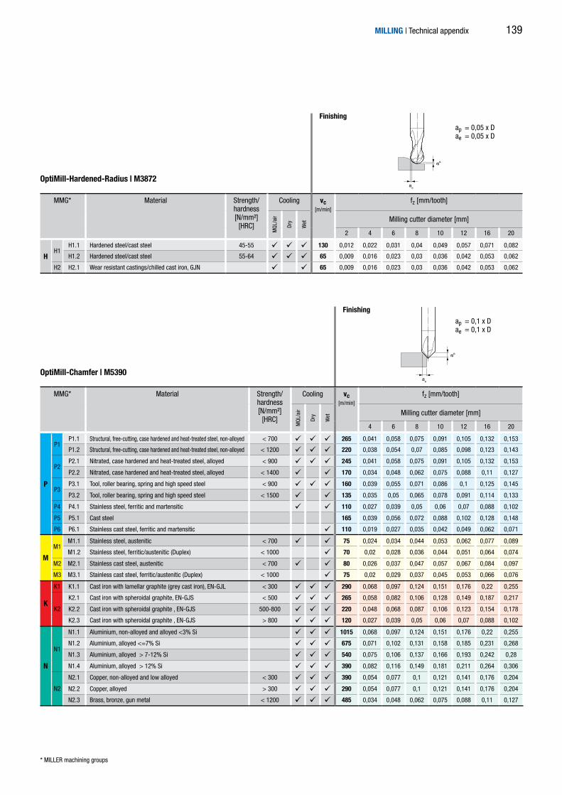
ae
a p
ae
a p
OptiMill-Hardened-Radius | M3872
* MILLER machining groups
ap = 0,05 x Dae = 0,05 x D
Finishing
MILLING | Technical appendix
OptiMill-Chamfer | M5390
ap = 0,1 x Dae = 0,1 x D
Finishing
MMG* Material Strength/hardness [N/mm²]
[HRC]
Cooling vc[m/min]
fz [mm/tooth]
MQL
/air
Dry
Wet Milling cutter diameter [mm]
2 4 6 8 10 12 16 20
HH1
H1.1 Hardened steel/cast steel 45-55 130 0,012 0,022 0,031 0,04 0,049 0,057 0,071 0,082
H1.2 Hardened steel/cast steel 55-64 65 0,009 0,016 0,023 0,03 0,036 0,042 0,053 0,062
H2 H2.1 Wear resistant castings/chilled cast iron, GJN 65 0,009 0,016 0,023 0,03 0,036 0,042 0,053 0,062
MMG* Material Strength/hardness [N/mm²]
[HRC]
Cooling vc[m/min]
fz [mm/tooth]
MQL
/air
Dry
Wet Milling cutter diameter [mm]
4 6 8 10 12 16 20
P
P1P1.1 Structural, free-cutting, case hardened and heat-treated steel, non-alloyed < 700 265 0,041 0,058 0,075 0,091 0,105 0,132 0,153
P1.2 Structural, free-cutting, case hardened and heat-treated steel, non-alloyed < 1200 220 0,038 0,054 0,07 0,085 0,098 0,123 0,143
P2P2.1 Nitrated, case hardened and heat-treated steel, alloyed < 900 245 0,041 0,058 0,075 0,091 0,105 0,132 0,153
P2.2 Nitrated, case hardened and heat-treated steel, alloyed < 1400 170 0,034 0,048 0,062 0,075 0,088 0,11 0,127
P3P3.1 Tool, roller bearing, spring and high speed steel < 900 160 0,039 0,055 0,071 0,086 0,1 0,125 0,145
P3.2 Tool, roller bearing, spring and high speed steel < 1500 135 0,035 0,05 0,065 0,078 0,091 0,114 0,133
P4 P4.1 Stainless steel, ferritic and martensitic 110 0,027 0,039 0,05 0,06 0,07 0,088 0,102
P5 P5.1 Cast steel 165 0,039 0,056 0,072 0,088 0,102 0,128 0,148
P6 P6.1 Stainless cast steel, ferritic and martensitic 110 0,019 0,027 0,035 0,042 0,049 0,062 0,071
M
M1M1.1 Stainless steel, austenitic < 700 75 0,024 0,034 0,044 0,053 0,062 0,077 0,089
M1.2 Stainless steel, ferritic/austenitic (Duplex) < 1000 70 0,02 0,028 0,036 0,044 0,051 0,064 0,074
M2 M2.1 Stainless cast steel, austenitic < 700 80 0,026 0,037 0,047 0,057 0,067 0,084 0,097
M3 M3.1 Stainless cast steel, ferritic/austenitic (Duplex) < 1000 75 0,02 0,029 0,037 0,045 0,053 0,066 0,076
K
K1 K1.1 Cast iron with lamellar graphite (grey cast iron), EN-GJL < 300 290 0,068 0,097 0,124 0,151 0,176 0,22 0,255
K2
K2.1 Cast iron with spheroidal graphite, EN-GJS < 500 265 0,058 0,082 0,106 0,128 0,149 0,187 0,217
K2.2 Cast iron with spheroidal graphite , EN-GJS 500-800 220 0,048 0,068 0,087 0,106 0,123 0,154 0,178
K2.3 Cast iron with spheroidal graphite , EN-GJS > 800 120 0,027 0,039 0,05 0,06 0,07 0,088 0,102
N
N1
N1.1 Aluminium, non-alloyed and alloyed <3% Si 1015 0,068 0,097 0,124 0,151 0,176 0,22 0,255
N1.2 Aluminium, alloyed <=7% Si 675 0,071 0,102 0,131 0,158 0,185 0,231 0,268
N1.3 Aluminium, alloyed > 7-12% Si 540 0,075 0,106 0,137 0,166 0,193 0,242 0,28
N1.4 Aluminium, alloyed > 12% Si 390 0,082 0,116 0,149 0,181 0,211 0,264 0,306
N2
N2.1 Copper, non-alloyed and low alloyed < 300 390 0,054 0,077 0,1 0,121 0,141 0,176 0,204
N2.2 Copper, alloyed > 300 290 0,054 0,077 0,1 0,121 0,141 0,176 0,204
N2.3 Brass, bronze, gun metal < 1200 485 0,034 0,048 0,062 0,075 0,088 0,11 0,127
139

ae
a p
OptiMill-DrillMill | M5490
* MILLER machining groups
ap = 1 x Dae = 1 x D
Groove milling
MILLING | Technical appendix
Cutting data recommendation for drill milling cuttersFeed and cutting speed
MMG* Material Strength/hardness [N/mm²]
[HRC]
Cooling vc[m/min]
fz [mm/tooth] vc[m/min]
fz [mm/tooth] vc[m/min]
fz [mm/tooth]
MQL
/air
Dry
Wet Milling cutter diameter [mm] Milling cutter diameter [mm] Milling cutter diameter [mm]
2 4 6 8 10 12 16 20 2 4 6 8 10 12 16 20 2 4 6 8 10 12 16 20
P
P1P1.1 Structural, free-cutting, case hardened and heat-treated steel, non-alloyed < 700 120 0,008 0,014 0,02 0,025 0,031 0,036 0,045 0,052 245 0,013 0,023 0,033 0,043 0,052 0,061 0,076 0,088 355 0,021 0,037 0,053 0,068 0,082 0,096 0,12 0,139
P1.2 Structural, free-cutting, case hardened and heat-treated steel, non-alloyed < 1200 95 0,007 0,013 0,018 0,024 0,029 0,033 0,042 0,048 200 0,012 0,022 0,031 0,04 0,049 0,057 0,071 0,082 290 0,02 0,035 0,049 0,063 0,077 0,09 0,112 0,13
P2P2.1 Nitrated, case hardened and heat-treated steel, alloyed < 900 110 0,008 0,014 0,02 0,025 0,031 0,036 0,045 0,052 220 0,013 0,023 0,033 0,043 0,052 0,061 0,076 0,088 325 0,021 0,037 0,053 0,068 0,082 0,096 0,12 0,139
P2.2 Nitrated, case hardened and heat-treated steel, alloyed < 1400 75 0,007 0,012 0,016 0,021 0,026 0,03 0,037 0,043 155 0,011 0,02 0,028 0,036 0,043 0,051 0,063 0,073 225 0,017 0,031 0,044 0,057 0,069 0,08 0,1 0,116
P3P3.1 Tool, roller bearing, spring and high speed steel < 900 70 0,007 0,013 0,019 0,024 0,029 0,034 0,043 0,049 145 0,013 0,022 0,032 0,041 0,05 0,058 0,072 0,084 210 0,02 0,035 0,05 0,065 0,078 0,091 0,114 0,132
P3.2 Tool, roller bearing, spring and high speed steel < 1500 60 0,007 0,012 0,017 0,022 0,027 0,031 0,039 0,045 120 0,012 0,02 0,029 0,037 0,045 0,053 0,066 0,076 180 0,018 0,032 0,046 0,059 0,071 0,083 0,104 0,121
P4 P4.1 Stainless steel, ferritic and martensitic 50 0,005 0,009 0,013 0,017 0,021 0,024 0,03 0,035 100 0,009 0,016 0,022 0,029 0,035 0,041 0,051 0,059 145 0,014 0,025 0,035 0,045 0,055 0,064 0,08 0,093
P5 P5.1 Cast steel 70 0,008 0,013 0,019 0,025 0,03 0,035 0,043 0,05 150 0,013 0,023 0,032 0,042 0,05 0,059 0,074 0,085 215 0,02 0,036 0,051 0,066 0,08 0,093 0,116 0,135
P6 P6.1 Stainless cast steel, ferritic and martensitic 50 0,004 0,006 0,009 0,012 0,014 0,017 0,021 0,024 100 0,006 0,011 0,016 0,02 0,024 0,028 0,035 0,041 145 0,01 0,017 0,025 0,032 0,038 0,045 0,056 0,065
M
M1M1.1 Stainless steel, austenitic < 700 30 0,005 0,008 0,011 0,015 0,018 0,021 0,026 0,03 65 0,008 0,014 0,02 0,025 0,03 0,035 0,044 0,051 95 0,012 0,022 0,031 0,04 0,048 0,056 0,07 0,081
M1.2 Stainless steel, ferritic/austenitic (Duplex) < 1000 30 0,004 0,007 0,01 0,012 0,015 0,017 0,022 0,025 60 0,006 0,011 0,016 0,021 0,025 0,029 0,037 0,043 90 0,01 0,018 0,026 0,033 0,04 0,046 0,058 0,067
M2 M2.1 Stainless cast steel, austenitic < 700 35 0,005 0,009 0,012 0,016 0,019 0,023 0,028 0,033 75 0,008 0,015 0,021 0,027 0,033 0,038 0,048 0,056 105 0,013 0,024 0,033 0,043 0,052 0,061 0,076 0,088
M3 M3.1 Stainless cast steel, ferritic/austenitic (Duplex) < 1000 30 0,004 0,007 0,01 0,013 0,015 0,018 0,022 0,026 65 0,007 0,012 0,017 0,022 0,026 0,03 0,038 0,044 95 0,01 0,019 0,026 0,034 0,041 0,048 0,06 0,07
K
K1 K1.1 Cast iron with lamellar graphite (grey cast iron), EN-GJL < 300 130 0,013 0,023 0,033 0,042 0,051 0,06 0,075 0,087 265 0,022 0,039 0,056 0,072 0,087 0,101 0,127 0,147 390 0,035 0,062 0,088 0,113 0,137 0,16 0,2 0,232
K2
K2.1 Cast iron with spheroidal graphite, EN-GJS < 500 120 0,011 0,02 0,028 0,036 0,044 0,051 0,064 0,074 245 0,019 0,033 0,047 0,061 0,074 0,086 0,108 0,125 355 0,03 0,053 0,075 0,096 0,117 0,136 0,17 0,197
K2.2 Cast iron with spheroidal graphite , EN-GJS 500-800 95 0,009 0,016 0,023 0,03 0,036 0,042 0,052 0,061 200 0,015 0,027 0,039 0,05 0,061 0,071 0,089 0,103 290 0,024 0,043 0,062 0,079 0,096 0,112 0,14 0,163
K2.3 Cast iron with spheroidal graphite , EN-GJS > 800 55 0,005 0,009 0,013 0,017 0,021 0,024 0,03 0,035 110 0,009 0,016 0,022 0,029 0,035 0,041 0,051 0,059 160 0,014 0,025 0,035 0,045 0,055 0,064 0,08 0,093
N
N1
N1.1 Aluminium, non-alloyed and alloyed <3% Si 450 0,013 0,023 0,033 0,042 0,051 0,06 0,075 0,087 925 0,022 0,039 0,056 0,072 0,087 0,101 0,127 0,147 1355 0,035 0,062 0,088 0,113 0,137 0,16 0,2 0,232
N1.2 Aluminium, alloyed <=7% Si 300 0,014 0,024 0,034 0,044 0,054 0,063 0,078 0,091 615 0,023 0,041 0,059 0,075 0,091 0,106 0,133 0,154 900 0,037 0,065 0,092 0,119 0,144 0,168 0,21 0,244
N1.3 Aluminium, alloyed > 7-12% Si 240 0,014 0,025 0,036 0,046 0,056 0,066 0,082 0,095 490 0,024 0,043 0,061 0,079 0,096 0,111 0,139 0,162 720 0,038 0,068 0,097 0,125 0,151 0,176 0,22 0,255
N1.4 Aluminium, alloyed > 12% Si 175 0,016 0,028 0,039 0,051 0,062 0,072 0,09 0,104 355 0,027 0,047 0,067 0,086 0,104 0,122 0,152 0,176 520 0,042 0,074 0,106 0,136 0,165 0,192 0,241 0,279
N2
N2.1 Copper, non-alloyed and low alloyed < 300 175 0,01 0,018 0,026 0,034 0,041 0,048 0,06 0,069 355 0,018 0,031 0,045 0,057 0,07 0,081 0,101 0,118 520 0,028 0,05 0,07 0,091 0,11 0,128 0,16 0,186
N2.2 Copper, alloyed > 300 130 0,01 0,018 0,026 0,034 0,041 0,048 0,06 0,069 265 0,018 0,031 0,045 0,057 0,07 0,081 0,101 0,118 390 0,028 0,05 0,07 0,091 0,11 0,128 0,16 0,186
N2.3 Brass, bronze, gun metal < 1200 215 0,007 0,012 0,016 0,021 0,026 0,03 0,037 0,043 440 0,011 0,02 0,028 0,036 0,043 0,051 0,063 0,073 650 0,017 0,031 0,044 0,057 0,069 0,08 0,1 0,116
140

ae
a p
ae
a p
ap = 1,5 x Dae = 0,25 x D
ap = 1,5 x Dae = 0,1 x D
Trimming Trimming
MILLING | Technical appendix
MMG* Material Strength/hardness [N/mm²]
[HRC]
Cooling vc[m/min]
fz [mm/tooth] vc[m/min]
fz [mm/tooth] vc[m/min]
fz [mm/tooth]
MQL
/air
Dry
Wet Milling cutter diameter [mm] Milling cutter diameter [mm] Milling cutter diameter [mm]
2 4 6 8 10 12 16 20 2 4 6 8 10 12 16 20 2 4 6 8 10 12 16 20
P
P1P1.1 Structural, free-cutting, case hardened and heat-treated steel, non-alloyed < 700 120 0,008 0,014 0,02 0,025 0,031 0,036 0,045 0,052 245 0,013 0,023 0,033 0,043 0,052 0,061 0,076 0,088 355 0,021 0,037 0,053 0,068 0,082 0,096 0,12 0,139
P1.2 Structural, free-cutting, case hardened and heat-treated steel, non-alloyed < 1200 95 0,007 0,013 0,018 0,024 0,029 0,033 0,042 0,048 200 0,012 0,022 0,031 0,04 0,049 0,057 0,071 0,082 290 0,02 0,035 0,049 0,063 0,077 0,09 0,112 0,13
P2P2.1 Nitrated, case hardened and heat-treated steel, alloyed < 900 110 0,008 0,014 0,02 0,025 0,031 0,036 0,045 0,052 220 0,013 0,023 0,033 0,043 0,052 0,061 0,076 0,088 325 0,021 0,037 0,053 0,068 0,082 0,096 0,12 0,139
P2.2 Nitrated, case hardened and heat-treated steel, alloyed < 1400 75 0,007 0,012 0,016 0,021 0,026 0,03 0,037 0,043 155 0,011 0,02 0,028 0,036 0,043 0,051 0,063 0,073 225 0,017 0,031 0,044 0,057 0,069 0,08 0,1 0,116
P3P3.1 Tool, roller bearing, spring and high speed steel < 900 70 0,007 0,013 0,019 0,024 0,029 0,034 0,043 0,049 145 0,013 0,022 0,032 0,041 0,05 0,058 0,072 0,084 210 0,02 0,035 0,05 0,065 0,078 0,091 0,114 0,132
P3.2 Tool, roller bearing, spring and high speed steel < 1500 60 0,007 0,012 0,017 0,022 0,027 0,031 0,039 0,045 120 0,012 0,02 0,029 0,037 0,045 0,053 0,066 0,076 180 0,018 0,032 0,046 0,059 0,071 0,083 0,104 0,121
P4 P4.1 Stainless steel, ferritic and martensitic 50 0,005 0,009 0,013 0,017 0,021 0,024 0,03 0,035 100 0,009 0,016 0,022 0,029 0,035 0,041 0,051 0,059 145 0,014 0,025 0,035 0,045 0,055 0,064 0,08 0,093
P5 P5.1 Cast steel 70 0,008 0,013 0,019 0,025 0,03 0,035 0,043 0,05 150 0,013 0,023 0,032 0,042 0,05 0,059 0,074 0,085 215 0,02 0,036 0,051 0,066 0,08 0,093 0,116 0,135
P6 P6.1 Stainless cast steel, ferritic and martensitic 50 0,004 0,006 0,009 0,012 0,014 0,017 0,021 0,024 100 0,006 0,011 0,016 0,02 0,024 0,028 0,035 0,041 145 0,01 0,017 0,025 0,032 0,038 0,045 0,056 0,065
M
M1M1.1 Stainless steel, austenitic < 700 30 0,005 0,008 0,011 0,015 0,018 0,021 0,026 0,03 65 0,008 0,014 0,02 0,025 0,03 0,035 0,044 0,051 95 0,012 0,022 0,031 0,04 0,048 0,056 0,07 0,081
M1.2 Stainless steel, ferritic/austenitic (Duplex) < 1000 30 0,004 0,007 0,01 0,012 0,015 0,017 0,022 0,025 60 0,006 0,011 0,016 0,021 0,025 0,029 0,037 0,043 90 0,01 0,018 0,026 0,033 0,04 0,046 0,058 0,067
M2 M2.1 Stainless cast steel, austenitic < 700 35 0,005 0,009 0,012 0,016 0,019 0,023 0,028 0,033 75 0,008 0,015 0,021 0,027 0,033 0,038 0,048 0,056 105 0,013 0,024 0,033 0,043 0,052 0,061 0,076 0,088
M3 M3.1 Stainless cast steel, ferritic/austenitic (Duplex) < 1000 30 0,004 0,007 0,01 0,013 0,015 0,018 0,022 0,026 65 0,007 0,012 0,017 0,022 0,026 0,03 0,038 0,044 95 0,01 0,019 0,026 0,034 0,041 0,048 0,06 0,07
K
K1 K1.1 Cast iron with lamellar graphite (grey cast iron), EN-GJL < 300 130 0,013 0,023 0,033 0,042 0,051 0,06 0,075 0,087 265 0,022 0,039 0,056 0,072 0,087 0,101 0,127 0,147 390 0,035 0,062 0,088 0,113 0,137 0,16 0,2 0,232
K2
K2.1 Cast iron with spheroidal graphite, EN-GJS < 500 120 0,011 0,02 0,028 0,036 0,044 0,051 0,064 0,074 245 0,019 0,033 0,047 0,061 0,074 0,086 0,108 0,125 355 0,03 0,053 0,075 0,096 0,117 0,136 0,17 0,197
K2.2 Cast iron with spheroidal graphite , EN-GJS 500-800 95 0,009 0,016 0,023 0,03 0,036 0,042 0,052 0,061 200 0,015 0,027 0,039 0,05 0,061 0,071 0,089 0,103 290 0,024 0,043 0,062 0,079 0,096 0,112 0,14 0,163
K2.3 Cast iron with spheroidal graphite , EN-GJS > 800 55 0,005 0,009 0,013 0,017 0,021 0,024 0,03 0,035 110 0,009 0,016 0,022 0,029 0,035 0,041 0,051 0,059 160 0,014 0,025 0,035 0,045 0,055 0,064 0,08 0,093
N
N1
N1.1 Aluminium, non-alloyed and alloyed <3% Si 450 0,013 0,023 0,033 0,042 0,051 0,06 0,075 0,087 925 0,022 0,039 0,056 0,072 0,087 0,101 0,127 0,147 1355 0,035 0,062 0,088 0,113 0,137 0,16 0,2 0,232
N1.2 Aluminium, alloyed <=7% Si 300 0,014 0,024 0,034 0,044 0,054 0,063 0,078 0,091 615 0,023 0,041 0,059 0,075 0,091 0,106 0,133 0,154 900 0,037 0,065 0,092 0,119 0,144 0,168 0,21 0,244
N1.3 Aluminium, alloyed > 7-12% Si 240 0,014 0,025 0,036 0,046 0,056 0,066 0,082 0,095 490 0,024 0,043 0,061 0,079 0,096 0,111 0,139 0,162 720 0,038 0,068 0,097 0,125 0,151 0,176 0,22 0,255
N1.4 Aluminium, alloyed > 12% Si 175 0,016 0,028 0,039 0,051 0,062 0,072 0,09 0,104 355 0,027 0,047 0,067 0,086 0,104 0,122 0,152 0,176 520 0,042 0,074 0,106 0,136 0,165 0,192 0,241 0,279
N2
N2.1 Copper, non-alloyed and low alloyed < 300 175 0,01 0,018 0,026 0,034 0,041 0,048 0,06 0,069 355 0,018 0,031 0,045 0,057 0,07 0,081 0,101 0,118 520 0,028 0,05 0,07 0,091 0,11 0,128 0,16 0,186
N2.2 Copper, alloyed > 300 130 0,01 0,018 0,026 0,034 0,041 0,048 0,06 0,069 265 0,018 0,031 0,045 0,057 0,07 0,081 0,101 0,118 390 0,028 0,05 0,07 0,091 0,11 0,128 0,16 0,186
N2.3 Brass, bronze, gun metal < 1200 215 0,007 0,012 0,016 0,021 0,026 0,03 0,037 0,043 440 0,011 0,02 0,028 0,036 0,043 0,051 0,063 0,073 650 0,017 0,031 0,044 0,057 0,069 0,08 0,1 0,116
141

Innovation, precision, variety! Three specialists deliver the perfect tools for success in your retail business.
Best in reaming and countersinking
The competence and experience from more than 100 years make BECK a dependable partner in demand for bore machining. The comprehensive standard programme includes reaming and countersinking tools and covers the complete cutting material spectrum from HSS to PCD and PcBN.This programme is supplemented by high performance reamers and custom tools that offer users thatcrucial performance plus.
Innovative drilling and milling
One of the largest and most modern factories for solid carbide tools in Europe produces drills and end-mills that have yet to find their equal. Because when it comes to high-precision standard solutions for drilling and milling, MILLER is the acknowledged specialist. The diverse programme line consists of solid carbide tools for almost any application. Know-how, quality and focus on retail business are the features that best describe our company and our products.
Reliable clamping technology
WTE is the specialist in innovative tool adapters. The extensive product line of Precision Drill Chucks,Hydraulic Chucks, Shrink Chucks, HPH Universal Chucks and MICRO Chucks fills every need for modern high-precision machining. WTE stands for precision and quality combined with high competence as a reliable clamping systems partner for your retail business.

tool-tra
Three goodreasons formore success
"Made in Germany"Top services and top products
We are convinced that the high demands of precision-dependent industries are met only by products developed and manufactured in Germany. The most modern manufacturing processes, production systems and infrastructure as well as qualified and dedicated emplo-yees make it possible to achieve very high performance standards. That means the highest quality features in the μ range for our pro-ducts, combined with an attractive price-to-performance ratio. All companies in „tool-traders-partner“ have active quality management systems and are certified in accordance with ISO 9001.
Technical competence – available worldwide
All the companies in “tool-traders-partner” are technolo-gy leaders and their brands enjoy a high level of familiarity internationally and an excellent image. With our practically ori-ented tool specialists, we have access to a pool of informati-on from decades of experience and collective specialist know-ledge. We stand for continuity, technological competence and innovative strength. For retail business this means: Always being in touch with the latest in tool technology and know-how.
Optimum customer service
Our extensive range of products available from stock, effici-ent logistics and high flexibility guarantee very high availabili-ty of products for retail. As part of our strategic alignment with retail business, we offer a whole package of services such as sales consulting, support from application specialists, training courses and marketing support. This makes it possible for you to continuously expand your competence while ensuring unparalleled service for you and your customers.

www.miller-tools.de
Order No. 10135798FRA2016-EN-PC-20-030-1216-GS Printed in Germany. Right of technical modifications reserved.
The specialist for
solid carbide drills and end-mills
Solid carbide drills for steel, aluminium,
stainless steel and hardened materials
High performance drills with more cutting
edges and additional guiding chamfers
TTD replaceable head drills
Solid carbide end-mill range for steel, aluminium,
stainless steel, plastics and hardened materials
High performance end-mills
for high machining volumes
Tooling programme for the machining of
advanced materials and super alloys
MIL
LER
stan
dard
pro
gram
me
– so
lid c
arbi
de e
nd-m
ills
The tool specialists for the trade.

1
HA
DIN 6535
HB
DIN 6535
DIN6527
DIN6535
2
3
4
5
P 1 2 3 4 5 6 M 1 2 3 K 1 2 3 N 1 2 3 4 S 1 2 3 4 5 H 1 2
N 1.1 1.2 1.3 1.4 2.1 2.2 2.3 3.1 4.1 4.2 4.3 C 1.1 1.2 1.3 2.1 3.1 4.1 4.2 4.3 4.4 5.1 5.2
MILLERNORM
Pictograms
End-mills with fixed cutting edges
Groove milling
Roughing
Profile milling
Finishing
Chamfering
Trochoidal milling
Trimming
Design
Product class
Material suitability
Design
Monolithic
45° chamfer
Drill tip
Sharp edged Corner radius Full radius
Cylindrical shank in accordance with DIN 6535
Cylindrical shank in accordance with DIN 6535
Short Long Overlong Extra long
For lateral material removal rates
For lateral material removal rates and for inclined entry
For lateral material re- moval rates, for inclined entry and recessing
Design DIN 6527
Design DIN 6535
In accordance with works standard
Basic Line: Universal tools, broad application area,low procurement costs
Performance Line: High-performance tools, broad application area, high productivity in series production manufacturing
Expert Line: Specialist tools for selected applications, maximum precision and productivity
Highlysuitable
Suitable in some situations
Example standard material suitability table
Example material suitability table for non-ferrous metals and lightweight materials
Internal cooling
C
NOTE:On request we would be pleased to provide you with information on prices and availability for the products in this catalogue.
Miller GmbH & Co. KG, PräzisionswerkzeugeIm Tal 12, 89281 Altenstadt, GermanyTelephone +49 8337 727-0Telefax +49 8337 [email protected]

P
P1P1.1 < 700 N/mm² 1.0122 (S235/St 37), 1.0401 (C15), 1.0503 (C45), 1.0570 (S355/St 52), 1.1213 (Cf53)
P1.2 < 1200 N/mm² 1.1249 (Cf70)
P2P2.1 < 900 N/mm² 1.7131 (16MnCr5)
P2.2 < 1400 N/mm² 1.7227 (42CrMoS4)
P3P3.1 < 900 N/mm² 1.2343 (X38CrMoV5-1)
P3.2 < 1500 N/mm² 1.3505 (100Cr6)
P4 P4.1 1.4510 (X3CrTi17), 1.4589 (X5CrNiMoTi15-2)
P5 P5.1 1.7231 (G42CrMo4)
P6 P6.1
MM1
M1.1 < 700 N/mm² 1.4301 (V2A), 1.4571 (V4A)
M1.2 < 1000 N/mm² 1.4362 (Alloy 2304), 1.4501, 1.4662 (LDX 2404)
M2 M2.1 < 700 N/mm²
M3 M3.1 < 1000 N/mm²
K
K1 K1.1 < 300 N/mm² GJL-250 (GG-25), GJL-260 (GG-26 Cr)
K2K2.1 < 500 N/mm² GJS-400 (GGG-40), GJS-450 (GGG-45)
K2.2 500-800 N/mm² GJS-600 (GGG-60), GJS-800-2 (GGG-80), GJS-800-8 (ADI 800)
K2.3 > 800 N/mm² GJS-900-2 (GGG-90), GJS-1000-5 (ADI 1000), GJS-1200-2 (ADI 1200), GJS-1400-1 (ADI 1400)
K3K3.1 < 500 N/mm² GJV-300, GJV-400, GJMW-400-5 (GTW-40)
K3.2 > 500 N/mm² GJV-500, GJV-700
N
N1
N1.1 Alloy 2024, Alloy 7075, Al99
N1.2 AlSi7
N1.3 AlSi9, AlSi9Cu
N1.4 AlSi12, AlSi17
N2N2.1 < 300 N/mm² SE-Cu
N2.2 > 300 N/mm² CuSn6
N2.3 < 1200 N/mm² CuZn33, CuAl9Mn3
N3 N3.1
N4N4.1 PA, PE, PC, PS, PVC, PP, PTFE, POM, PMMA
N4.2 PU, PF, EP, UP, VE, CR
N4.3 EPS, PUR, PVC-E, PS-E, PP-E
C
C1C1.1 Nomex, Kevlar, Twaron, KOREX
C1.2 IMS, HTA
C1.3 GMT-PP, PEEK
C2 C2.1 CF222, CF225, CF226, CF227, CF260
C3 C3.1 CeramTec AO-403 (AlSi9MgMn-Al2O3), Al/Cu/Mg-SiO2/Al2O3/AlN/TiC/SiC/BN/TiB2
C4
C4.1
C4.2 PLASCORE PAMG-XR1 5052, PCGA-XR1 3003, PAMG-XR1 5056, Micro-Cell (core = alloy 5052/5056)
C4.3CORMASTER, TUBUS, KOREX, HFT-G, TPU, HFT, HRH
(HRH-10, HRH-310, HRH-78, HRH-49, HRH-327), HDC-F
C4.4 AIREX R63, AIREX C70, ROHACELL IG-F
C5C5.1 IMS/HTA + Alloy 2024/6061/7075
C5.2 IMS/HTA + TiAl6V4/AMS4905
S
S1 S1.1 < 400 N/mm²
S2S2.1 < 1200 N/mm² TiAl6V4
S2.2 > 1200 N/mm²
S3S3.1 < 900 N/mm² 1.3912 (Invar, Ni36)
S3.2 > 900 N/mm²
S4 S4.1 Hardox, Hastelloy, Incoloy, Inconel, NIMONIC, Stellite, Waspaloy
S5 S5.1
HH1
H1.1 45-55 HRC
H1.2 55-64 HRC
H1.3 64-70 HRCH2 H2.1
MILLER machining groupsThe MILLER machining groups make it possible to provide precise information on the suitability of a tool for certain workpiece materials. Crucial for the categorisation of the groups is the machinability in relation to the cutting data (cutting speed and feed) for a material. It is necessary to sub-divide certain workpiece material groups based on the strength/hardness of the related workpiece material.
Machining group Material Strength - Hardness
[N/mm² - HRC] Frequently machined workpiece materials
Structural, free-cutting, case hardened and heat-treated steel, non-alloyed
Structural, free-cutting, case hardened and heat-treated steel, non-alloyed
Nitrated, case hardened and heat-treated steel, alloyed
Nitrated, case hardened and heat-treated steel, alloyed
Tool, roller bearing, spring and high speed steel
Tool, roller bearing, spring and high speed steel
Stainless steel, ferritic and martensitic
Cast steel
Stainless cast steel, ferritic and martensitic
Stainless steel, austenitic
Stainless steel, ferritic/austenitic (Duplex)
Stainless cast steel, austenitic
Stainless cast steel, ferritic/austenitic (Duplex)
Cast iron with lamellar graphite (grey cast iron), EN-GJL
Cast iron with spheroidal graphite, EN-GJS
Cast iron with spheroidal graphite , EN-GJS
Cast iron with spheroidal graphite , EN-GJS
Cast iron with vermicular graphite, EN-GJV; Malleable cast iron, GJM
Cast iron with vermicular graphite, EN-GJV; Malleable cast iron, GJM
Aluminium, non-alloyed and alloyed <3% Si
Aluminium, alloyed ≤ 7% Si
Aluminium, alloyed > 7-12% Si
Aluminium, alloyed > 12% Si
Copper, non-alloyed and low alloyed
Copper, alloyed
Brass, bronze, gun metal
Graphite
Plastic, thermoplastic
Plastic, thermosetting plastic (duroplast)
Plastic, foam
Plastic matrix, aramid fibre reinforced plastic (AFK)
Plastic matrix (thermosetting), CFRP/GFRP
Plastic matrix (thermoplastic), CFRP/GFRP
Carbon matrix, carbon fibre reinforced (CFC)
Metal matrix (MMC)
Sandwich construction, honeycomb core of paper
Sandwich construction, honeycomb core of aluminium
Sandwich construction, honeycomb core of plastic and fibre composite materials
Sandwich construction, core of rigid foam
Stack (hybrid structure) CFRP-aluminium
Stack (hybrid structure) CFRP-titanium/stainless steel
Titanium, titanium alloy
Titanium, titanium alloy
Titanium, titanium alloy
Nickel, non-alloyed and alloyed
Nickel, non-alloyed and alloyed
Heat resistant super alloys, Ni, Co, and Fe based
Tungsten and molybdenum alloys
Hardened steel/cast steel
Hardened steel/cast steel
Hardened steel/cast steelWear resistant castings/chilled cast iron, GJN