Solid Cam 2009 Milling User Guide
864
Power and Ease of Use - the winning combination ©1995-2009 SolidCAM All Rights Reserved. WWW.SOLIDCAM.COM SolidCAM 2009 Milling User Guide The Leaders in Integrated CAM SolidCAM 2009
-
Upload
guest3f0c6c -
Category
Business
-
view
8.761 -
download
17
Transcript of Solid Cam 2009 Milling User Guide
Power and Ease of Use - the winning combination
©1995-2009 SolidCAM
All Rights Reserved.WWW.SOLIDCAM.COM
SolidCAM 2009
Milling User Guide
The Leaders in Integrated CAMSolidCAM 2009


SolidCAM 2009
Milling User Guide
©1995-2009 SolidCAM
All Rights Reserved.


Contents
5
Contents
1. SolidCAM Basics
1.1 Installing the SolidCAM Software .................................................................................................... 24
1.1.1 System requirements ................................................................................................................. 24
1.1.2 Supported CAD systems ......................................................................................................... 24
1.1.3 SolidCAM Single License installation .................................................................................... 25
1.1.4 SolidCAM Network License Installation .............................................................................. 29
1.2 Basic Concepts ..................................................................................................................................... 31
1.3 Starting SolidCAM............................................................................................................................... 31
1.4 SolidCAM Interface ............................................................................................................................ 32
1.4.1 SolidCAM Manager .................................................................................................................. 32
1.4.2 Coordinate System .................................................................................................................... 35
1.5 Getting Help ......................................................................................................................................... 36
2. CAM-Part
2.1 Starting a new Milling CAM-Part ...................................................................................................... 38
2.1.1 New Milling Part dialog box.................................................................................................... 39
2.1.2 The structure of the CAM-Part.............................................................................................. 40
2.1.3 Milling Part Data dialog box ................................................................................................... 40
2.2 Coordinate System ............................................................................................................................... 41
2.2.1 Defining the Coordinate System (CoordSys)........................................................................ 41
2.2.2 CoordSys dialog box ................................................................................................................. 42
2.2.3 Defining the Coordinate Systems for 3-axis CNC-machine .............................................. 48
2.2.4 Defining the Coordinate Systems for 4-axis CNC-machine .............................................. 49
2.2.5 Defining the Coordinate Systems for 5-axis CNC-machine .............................................. 50
2.2.6 Coordinate System definition methods ................................................................................. 51
2.2.7 CoordSys Data dialog box ....................................................................................................... 52

6
2.2.8 SolidCAM Coordinate System ................................................................................................ 54
2.3 CoordSys Manager .............................................................................................................................. 55
2.4 Stock and Target Model ...................................................................................................................... 57
2.4.1 Stock model ............................................................................................................................... 58
2.4.2 Target model .............................................................................................................................. 60
2.4.3 Common controls for Stock model and Target model dialog boxes ................................ 60
2.4.4 Associativity of Stock and Target models ............................................................................. 61
2.5 Tool Options ........................................................................................................................................ 63
2.6 Mac Options ......................................................................................................................................... 65
2.7 Work Material ....................................................................................................................................... 65
2.8 CNC-Controller and Axis Type ......................................................................................................... 66
2.8.1 Axis type ..................................................................................................................................... 66
2.9 Default GCode numbers .................................................................................................................... 68
2.10 Part Settings ........................................................................................................................................ 70
2.10.1 Units .......................................................................................................................................... 70
2.10.2 Interoperational tool movements ......................................................................................... 71
2.10.3 Update Stock calculation ....................................................................................................... 72
2.10.4 Synchronization ....................................................................................................................... 75
2.10.5 Automatic CAM-Part definition ........................................................................................... 76
2.10.6 Machining Process .................................................................................................................. 78
2.10.7 Tool path simulation ............................................................................................................... 79
2.10.8 GCode generation ................................................................................................................... 80
2.10.9 Template defaults .................................................................................................................... 84
2.10.10 Tool coolant ........................................................................................................................... 86
2.10.11 Gouge check .......................................................................................................................... 86
2.11 Compressed CAM-Part .................................................................................................................... 87
2.11.1 Compressed CAM-Part file format ...................................................................................... 87
2.11.2 Creating a new compressed CAM-Part ............................................................................... 87
2.11.3 Converting CAM-Parts to Compressed mode ................................................................... 88
2.11.4 Opening/Closing Compressed CAM-Parts ........................................................................ 88
Contents
7
2.12 Managing CAM-Parts ....................................................................................................................... 90
2.13 CAM-Part Documentation .............................................................................................................. 97
2.13.1 Documentation Editor ........................................................................................................... 97
2.14 Tool sheet documentation ................................................................................................................ 99
2.14.1 Capturing the CAM-Part image ............................................................................................ 99
2.14.2 Definition of tool sheet parameters .................................................................................. 100
2.14.3 The output file ....................................................................................................................... 103
2.14.4 Show Last Tool Sheet ........................................................................................................... 107
2.15 Milling STL CAM-Part ................................................................................................................... 108
2.15.1 Starting a new Milling-STL CAM-Part .............................................................................. 108
2.15.2 Coordinate System definition .............................................................................................. 110
2.15.3 Stock model definition ......................................................................................................... 111
2.15.4 Target model definition........................................................................................................ 111
2.16 Support of DriveWorks .................................................................................................................. 112
3. Tools
3.1 User-Defined Tool Types ................................................................................................................. 116
3.1.1 End mill .................................................................................................................................... 117
3.1.2 Ball nose mill............................................................................................................................ 118
3.1.3 Bull nose mill ........................................................................................................................... 119
3.1.4 Dove tail mill ........................................................................................................................... 120
3.1.5 Face mill ....................................................................................................................................121
3.1.6 Slot mill ..................................................................................................................................... 122
3.1.7 Taper mill ................................................................................................................................. 123
3.1.8 Engraving tool ......................................................................................................................... 125
3.1.9 Tap tool.....................................................................................................................................126
3.1.10 Lollipop mill .......................................................................................................................... 127
3.1.11 Thread mill ............................................................................................................................. 129
3.1.12 Thread taper .......................................................................................................................... 131
3.1.13 Drill .........................................................................................................................................131
8
3.1.14 Center drill ............................................................................................................................. 132
3.1.15 Spot drill ................................................................................................................................. 134
3.1.16 Chamfer drill .......................................................................................................................... 135
3.1.17 Reamer .................................................................................................................................... 136
3.1.18 Bore .........................................................................................................................................137
3.1.19 Shaped Tools ......................................................................................................................... 138
3.1.20 Add new tool types ............................................................................................................... 138
3.1.21 Tool type options .................................................................................................................. 139
3.2 Tool Libraries ..................................................................................................................................... 140
3.3 Working with the Part Tool Table ................................................................................................... 141
3.4 Working with the Current Tool Library ......................................................................................... 142
3.5 Managing Tool Libraries ................................................................................................................... 143
3.5.1 Edit Tool Library .................................................................................................................... 143
3.5.2 Create Tool Library ................................................................................................................. 143
3.5.3 Copy Tool Library ................................................................................................................... 144
3.5.4 Delete Tool Library ................................................................................................................ 145
3.6 Tool Table dialog box ....................................................................................................................... 146
3.6.1 Tools Filter ............................................................................................................................... 146
3.6.2 Tool range ................................................................................................................................ 147
3.6.3 Show ..........................................................................................................................................148
3.6.4 View ..........................................................................................................................................149
3.6.5 Edit ............................................................................................................................................149
3.7 Managing tools ................................................................................................................................... 152
3.8 Tool data .............................................................................................................................................156
3.8.1 Tool Topology page ................................................................................................................ 157
3.8.2 Default Tool Data page .......................................................................................................... 161
3.8.3 Tool Message page .................................................................................................................. 164
3.8.4 Holder page .............................................................................................................................. 165
3.8.5 Tool Coolant page ................................................................................................................... 166
3.8.6 Shape page................................................................................................................................ 167
Contents
9
3.9 Tool Holding system ......................................................................................................................... 169
3.9.1 Tool Holders dialog box ........................................................................................................ 169
3.9.2 Tool Holder Geometry definition ........................................................................................ 173
3.9.3 Tool Holder segments ............................................................................................................ 173
3.9.4 Using Tool Holders ................................................................................................................ 175
3.10 Shaped Tools ....................................................................................................................................177
3.10.1 Shaped Tools dialog box ...................................................................................................... 177
3.10.2 Shaped tool geometry definition ........................................................................................ 180
3.10.3 Shaped Tool segments .......................................................................................................... 180
3.10.4 Using Shaped tools ............................................................................................................... 182
3.11 Feed and Speed defaults ................................................................................................................. 184
4. Geometry
4.1 Introduction .......................................................................................................................................188
4.2 Drilling geometry ............................................................................................................................... 189
4.2.1 Defining a Drilling geometry ................................................................................................ 189
4.2.2 Editing a Drilling geometry ................................................................................................... 190
4.2.3 Drill Geometry Selection dialog box ................................................................................... 190
4.2.4 Around 4th Axis Drill Geometry Selection dialog box .................................................... 194
4.3 3D Model geometry .......................................................................................................................... 197
4.3.1 Defining a 3D Model geometry ............................................................................................ 197
4.3.2 Editing a 3D Model geometry .............................................................................................. 198
4.4 Wireframe geometry ......................................................................................................................... 199
4.4.1 Defining the Profile/Pocket geometry ................................................................................ 199
4.4.2 Defining the Working Area ................................................................................................... 200
4.4.3 Defining the Slot geometry ................................................................................................... 200
4.4.4 Defining the Section geometry ............................................................................................. 201
4.4.5 Defining the Limit geometry ................................................................................................. 202
4.5 Editing chain geometries .................................................................................................................. 203

10
4.5.1 Geometry Name ..................................................................................................................... 203
4.5.2 Configurations ......................................................................................................................... 203
4.5.3 Adding a Chain ........................................................................................................................ 203
4.5.4 Managing chains ...................................................................................................................... 204
4.5.5 Chain direction ........................................................................................................................ 205
4.5.6 Selecting single entities ........................................................................................................... 205
4.5.7 Automatic selection ................................................................................................................ 209
4.5.8 Chain buttons .......................................................................................................................... 211
4.5.9 Options .....................................................................................................................................212
4.5.10 Gap control ............................................................................................................................ 212
4.5.11 Add Multi-Chain ................................................................................................................... 213
4.5.12 Mark Open Edges dialog box ............................................................................................. 213
4.6 Chains Selection dialog box ............................................................................................................. 215
4.6.1 Chains Direction dialog box .................................................................................................. 217
4.6.2 Chain sorting ........................................................................................................................... 218
4.7 Managing geometries ........................................................................................................................ 220
4.7.1 Synchronization of the Wireframe geometry ..................................................................... 221
4.7.2 Synchronization of the 3D Model geometry ..................................................................... 224
4.7.3 Boolean operations ................................................................................................................. 226
5. Operations
5.1 Adding an operation .......................................................................................................................... 230
5.2 SolidCAM Operation Interface ....................................................................................................... 231
5.2.1 Operation name ...................................................................................................................... 233
5.2.2 Template ................................................................................................................................... 235
5.2.3 Info ............................................................................................................................................245
5.2.4 Operation buttons ................................................................................................................... 245
5.2.5 Calculator ................................................................................................................................. 247
5.2.6 Geometry page ........................................................................................................................ 250
5.2.7 Tool page .................................................................................................................................. 252
5.2.8 Levels page ............................................................................................................................... 257

Contents
11
5.2.9 Technology page ..................................................................................................................... 264
5.2.10 Advanced Technology page ................................................................................................ 264
5.2.11 Link page ................................................................................................................................ 272
5.2.12 Miscellaneous parameters page ........................................................................................... 272
5.3 Working with operations .................................................................................................................. 275
5.3.1 Add Operation ........................................................................................................................ 275
5.3.2 Add Operation from Template ............................................................................................. 276
5.3.3 Add Operations from Process Template ............................................................................ 276
5.3.4 Add Machining Process ......................................................................................................... 277
5.3.5 Create Template ...................................................................................................................... 277
5.3.6 Edit ............................................................................................................................................277
5.3.7 Calculate/Calculate All ........................................................................................................... 277
5.3.8 GCode/GCode All ................................................................................................................. 277
5.3.9 Calculate & GCode All .......................................................................................................... 278
5.3.10 Tool Sheet .............................................................................................................................. 278
5.3.11 Simulate .................................................................................................................................. 278
5.3.12 File ...........................................................................................................................................278
5.3.13 Operation Group .................................................................................................................. 278
5.3.14 Cut/Copy/Paste .................................................................................................................... 279
5.3.15 Rename ................................................................................................................................... 279
5.3.16 Change tool ............................................................................................................................ 280
5.3.17 Change tool data ................................................................................................................... 280
5.3.18 Info ..........................................................................................................................................281
5.3.19 Delete/Delete All ................................................................................................................. 281
5.3.20 Suppress/Unsuppress .......................................................................................................... 281
5.4 Managing Operations in the SolidCAM Manager tree ................................................................ 284
5.4.1 Operation Sequence ............................................................................................................... 284
5.4.2 Undo Sequence........................................................................................................................ 284
5.4.3 Split............................................................................................................................................284
5.4.4 Expand tree .............................................................................................................................. 286
5.4.5 Collapse tree ............................................................................................................................. 286
12
5.4.6 Show/Hide Tools in tree ....................................................................................................... 286
5.4.7 Show/Hide CoordSys in tree ................................................................................................ 287
5.4.8 Automatic Sort ........................................................................................................................ 288
5.5 Operation Transformations ............................................................................................................. 290
5.5.1 Operation transformations .................................................................................................... 291
5.5.2 Options .....................................................................................................................................292
5.5.3 Transformations table ............................................................................................................ 292
5.5.4 Transformation buttons ......................................................................................................... 293
5.6 Fixture .................................................................................................................................................298
5.6.1 Fixture dialog box ................................................................................................................... 299
6. 2.5D Milling
6.1 Profile Operation ............................................................................................................................... 302
6.1.1 Levels page ............................................................................................................................... 303
6.1.2 Technology page ..................................................................................................................... 303
6.1.3 Link page .................................................................................................................................. 326
6.2 Face Milling Operation ..................................................................................................................... 335
6.2.1 Geometry page ........................................................................................................................ 335
6.2.2 Technology page ..................................................................................................................... 338
6.2.3 Link page .................................................................................................................................. 349
6.3 Contour 3D Operation ..................................................................................................................... 351
6.3.1 Technology page ..................................................................................................................... 351
6.3.2 Link page .................................................................................................................................. 355
6.4 Pocket Operation ............................................................................................................................... 357
6.4.1 Geometry page ........................................................................................................................ 358
6.4.2 Levels page ............................................................................................................................... 359
6.4.3 Technology page ..................................................................................................................... 360
6.4.4 Link page .................................................................................................................................. 381
6.5 Pocket Recognition Operation ........................................................................................................ 397
6.5.1 Geometry page ........................................................................................................................ 397

Contents
13
6.5.2 Levels page ............................................................................................................................... 403
6.5.3 Technology page ..................................................................................................................... 404
6.5.4 Link page .................................................................................................................................. 408
6.6 Drilling Operation ............................................................................................................................. 409
6.6.1 Tool page .................................................................................................................................. 409
6.6.2 Levels page ............................................................................................................................... 411
6.6.3 Technology page ..................................................................................................................... 412
6.7 Drill Recognition Operation ............................................................................................................ 437
6.7.1 Geometry page ........................................................................................................................ 437
6.7.2 Levels page ............................................................................................................................... 442
6.7.3 Technology page ..................................................................................................................... 446
6.8 Thread Milling Operation ................................................................................................................ 447
6.8.1 Tool page .................................................................................................................................. 447
6.8.2 Levels page ............................................................................................................................... 448
6.8.3 Technology page ..................................................................................................................... 449
6.8.4 Link page .................................................................................................................................. 452
6.9 Slot Operation .................................................................................................................................... 453
6.9.1 Technology page ..................................................................................................................... 454
6.9.2 Pre-drilling geometry generation .......................................................................................... 461
6.10 T-Slot Operation .............................................................................................................................. 463
6.10.1 Tool page ................................................................................................................................ 464
6.10.2 Technology page ................................................................................................................... 465
6.10.3 Link page ................................................................................................................................ 470
6.11 Translated Surface Operation ........................................................................................................ 471
6.11.1 Technology page ................................................................................................................... 471
6.11.2 Link page ................................................................................................................................ 482
7. 3D Milling
7.1 3D Milling Operation ........................................................................................................................ 484
7.1.1 Geometry page ........................................................................................................................ 484

14
7.1.2 Technology page ..................................................................................................................... 497
7.1.3 Roughing .................................................................................................................................. 498
7.1.4 Hatch roughing ........................................................................................................................ 513
7.1.5 Contour roughing ................................................................................................................... 513
7.1.6 Plunging pattern ...................................................................................................................... 513
7.1.7 Semi-Finish/Finish ................................................................................................................. 514
7.1.8 Semi-Finish/Finish strategies ................................................................................................ 520
7.1.9 Linear Finish strategy ............................................................................................................. 520
7.1.10 Offset Cutting Finish strategy............................................................................................. 524
7.1.11 Spiral finish strategy ............................................................................................................. 527
7.1.12 Circular Pocket finish strategy ............................................................................................ 531
7.1.13 Constant Z Finish Strategy .................................................................................................. 533
7.1.14 Constant Step over strategy................................................................................................. 540
7.1.15 Pencil milling ......................................................................................................................... 545
7.1.16 Tolerance page ....................................................................................................................... 549
7.2 3D Engraving Operation.................................................................................................................. 551
7.2.1 Technology page ..................................................................................................................... 551
7.2.2 Tolerance page ......................................................................................................................... 554
7.3 3D Drilling Operation ...................................................................................................................... 555
7.3.1 Geometry page ........................................................................................................................ 555
7.3.2 Tool page .................................................................................................................................. 556
7.3.3 Levels page ............................................................................................................................... 557
7.3.4 Technology page ..................................................................................................................... 557
8. Machining Processes
8.1 Introduction & Basic concepts ........................................................................................................ 560
8.1.1 Operation templates ............................................................................................................... 560
8.1.2 Parameters & Expressions ..................................................................................................... 561
8.1.3 Default sets .............................................................................................................................. 562
8.1.4 Machining Process Table ....................................................................................................... 562
8.2 Creating Machining Processes ......................................................................................................... 563
Contents
15
8.3 Defining Machining Process Table ................................................................................................. 564
8.3.1 Adding MAC file(s) ................................................................................................................. 564
8.4 Machining Process Table Manager ................................................................................................. 566
8.4.1 Managing Machining Process Tables ................................................................................... 567
8.4.2 Machining Process Group Types .......................................................................................... 569
8.5 Managing Machining Processes ....................................................................................................... 571
8.6 Machining Process Define Manager ............................................................................................... 572
8.6.1 Operation Templates page ..................................................................................................... 572
8.6.2 Define Operation Template .................................................................................................. 572
8.6.3 Managing Operation Templates............................................................................................ 573
8.6.4 Parametric field menu ............................................................................................................. 575
8.6.5 Default Sets page..................................................................................................................... 576
8.6.6 Parameters & Expressions Tables ........................................................................................ 577
8.6.7 Add new parameter ................................................................................................................ 579
8.6.8 Variables and expressions ...................................................................................................... 579
8.6.9 Parametric tool definition ...................................................................................................... 584
8.7 Using the Machining Processes ....................................................................................................... 586
8.8 Inserting the Machining Process ..................................................................................................... 587
8.8.1 Choosing the tool .................................................................................................................... 589
8.9 Machining Process Insert Manager ................................................................................................. 590
8.9.1 Operation Templates Page..................................................................................................... 590
8.9.2 Default Sets Page .................................................................................................................... 591
8.9.3 Parameters Table ..................................................................................................................... 592
8.9.4 Operation Points ..................................................................................................................... 592
8.9.5 Parameters definition .............................................................................................................. 592
9. Automatic Feature Recognition and Machining (AFRM)
9.1 Introduction and Basic Concepts .................................................................................................... 596
9.2 Preparation to Holes Recognition ................................................................................................... 598
16
9.2.1 Definition of Coordinate Systems ....................................................................................... 598
9.2.2 Target model ............................................................................................................................ 598
9.3 Start Holes Recognition .................................................................................................................... 599
9.4 Holes Recognition User Interface ................................................................................................... 600
9.4.1 Holes Recognition Manager .................................................................................................. 600
9.4.2 Holes Recognition Toolbar.................................................................................................... 601
9.5 Hole Feature Model ........................................................................................................................... 603
9.5.1 Cylindrical Hole Feature segment ......................................................................................... 604
9.5.2 Cone Hole Feature segment .................................................................................................. 604
9.5.3 Chamfer Hole Feature segment ............................................................................................ 605
9.5.4 Planar Hole Feature segment ................................................................................................ 605
9.5.5 Torus Hole Feature segment ................................................................................................. 605
9.5.6 Sphere Hole Feature segment ............................................................................................... 606
9.5.7 Compound Holes processing ................................................................................................ 606
9.5.8 Disconnected Holes processing ............................................................................................ 607
9.5.9 Reaming recognition ............................................................................................................... 607
9.5.10 Hole Feature Shapes and Groups....................................................................................... 607
9.5.11 Hole Features page ............................................................................................................... 608
9.6 Preparing Hole Features for machining ......................................................................................... 613
9.6.1 Undercut processing ............................................................................................................... 613
9.6.2 Undercut substitution ............................................................................................................. 614
9.6.3 Segments Union ...................................................................................................................... 617
9.6.4 Machinable Hole Features ..................................................................................................... 619
9.6.5 Machinable Hole Feature conversion .................................................................................. 625
9.6.6 Machinable Hole Features page ............................................................................................ 633
9.7 Feature Sets .........................................................................................................................................642
9.7.1 Creating Feature Sets .............................................................................................................. 642
9.7.2 Assigning Hole Features to Feature Sets ............................................................................. 642
9.7.3 Automatic CoordSys Positions definition ........................................................................... 643
9.7.4 Feature Sets page ..................................................................................................................... 645
9.7.5 Compatible/Incompatible Hole features ............................................................................ 645
Contents
17
9.7.6 Operating Feature Sets ........................................................................................................... 646
9.7.7 Defining the CoordSys Position origin location for the Feature Set .............................. 647
9.8 Technology .........................................................................................................................................649
9.8.1 Choosing a Technological Solution ...................................................................................... 649
9.8.2 Choosing the tool .................................................................................................................... 650
9.8.3 Technology Page ..................................................................................................................... 657
9.8.4 Managing Technology ............................................................................................................ 658
9.9 Generating Operations ..................................................................................................................... 661
9.10 Technology Database ...................................................................................................................... 662
9.10.1 Global and Local Technology databases ........................................................................... 663
9.10.2 Technology Database interface ........................................................................................... 664
9.10.3 Configurations page .............................................................................................................. 664
9.10.4 Current Configuration .......................................................................................................... 665
9.10.5 Solutions page ....................................................................................................................... 666
9.10.6 Conditions .............................................................................................................................. 667
9.10.7 Variables ................................................................................................................................. 670
9.10.8 Defining a new Technological Solution............................................................................. 673
9.10.9 Holes Recognition Functions.............................................................................................. 674
9.11 Holes Recognition Settings ............................................................................................................ 676
9.11.1 System settings ...................................................................................................................... 676
9.11.2 Part settings ............................................................................................................................ 679
10. Simulation
10.1 Introduction ..................................................................................................................................... 682
10.1.1 Simulation control panel ...................................................................................................... 682
10.1.2 Simulation modes .................................................................................................................. 684
10.1.3 Simulation controls ............................................................................................................... 684
10.2 2D simulation mode ........................................................................................................................ 685
10.2.1 Simulation toolbar ................................................................................................................. 685
10.2.2 Simulation control panel ...................................................................................................... 685
18
10.3 VerifyPlus simulation mode ........................................................................................................... 687
10.3.1 Simulation toolbar ................................................................................................................. 687
10.3.2 Buttons available in the Setup mode .................................................................................. 688
10.3.3 Buttons available in the Simulation mode ......................................................................... 690
10.4 Host CAD simulation mode .......................................................................................................... 691
10.5 3D simulation mode ........................................................................................................................ 692
10.5.1 Simulation toolbar ................................................................................................................. 692
10.5.2 Simulation menu ................................................................................................................... 693
10.6 SolidVerify simulation mode .......................................................................................................... 695
10.6.1 Simulation control panel .......................................................................................................695
10.6.2 Simulation toolbar ................................................................................................................. 696
10.6.3 Selection mode ...................................................................................................................... 700
10.6.4 Measurement ......................................................................................................................... 701
10.6.5 Updated Stock model ........................................................................................................... 701
10.6.6 Simulation menu ................................................................................................................... 703
10.7 SolidVerify for 3D simulation mode ............................................................................................ 710
10.7.1 Simulation control panel .......................................................................................................711
10.7.2 Rendering of the simulation model ................................................................................... 711
10.7.3 Simulation toolbar ................................................................................................................. 713
10.7.4 Simulation menu ................................................................................................................... 713
10.8 Rest Material simulation mode ...................................................................................................... 714
10.9 RapidVerify simulation mode ........................................................................................................ 715
10.9.1 RapidVerify control panel .................................................................................................... 715
10.9.2 Updated Stock Model ........................................................................................................... 716
10.9.3 Simulation control panel .......................................................................................................716
10.9.4 Simulation toolbar ................................................................................................................. 717
10.9.5 Simulation menu ....................................................................................................................718
10.10 Machine Simulation ....................................................................................................................... 719
10.10.1 Simulation menu ................................................................................................................. 720
10.10.2 Simulation windows ........................................................................................................... 732

Contents
19
10.10.3 Simulation toolbars ............................................................................................................. 741
10.10.4 CNC-machine definition parameters ............................................................................... 743
10.10.5 CNC-machine model definition ....................................................................................... 760
12. SolidCAM Settings
12.1 Introduction ..................................................................................................................................... 800
12.2 User Directories settings ................................................................................................................ 801
12.2.1 User Directory for SolidCAM Parts .................................................................................. 801
12.2.2 User Directory for SolidCAM Tables ................................................................................ 801
12.2.3 Excel file for Threading tables ............................................................................................ 801
12.3 Default CNC-controller settings ................................................................................................... 802
12.3.1 Post-processor files directory .............................................................................................. 802
12.3.2 CNC-controllers .................................................................................................................... 802
12.4 Units settings ....................................................................................................................................803
12.4.1 Metric/Inch ........................................................................................................................... 803
12.4.2 Approximation ...................................................................................................................... 803
12.4.3 Chain selection ...................................................................................................................... 804
12.4.4 Fillet size for last cut ............................................................................................................. 805
12.4.5 Tool Start and Clearance Levels ......................................................................................... 805
12.5 Synchronization settings ................................................................................................................. 806
12.5.1 Synchronization of CAM geometry with design model ................................................. 806
12.5.2 Synchronization tolerance ................................................................................................... 807
12.5.3 Synchronization of design model with original model ................................................... 807
12.5.4 Synchronization when design model configuration changes ......................................... 807
12.6 Compressed CAM-Part settings .................................................................................................... 808
12.7 Tool Settings .....................................................................................................................................810
12.7.1 Update Part Tool Table according to Machine Tool Table ............................................ 810
12.7.2 Print in documentation – Only used tools ........................................................................ 810
12.7.3 Show in SolidCAM Manager ............................................................................................... 810
12.7.4 Import tools ........................................................................................................................... 811

20
12.7.5 Set Tool as Permanent when user changes the tool number ......................................... 811
12.8 Color settings ................................................................................................................................... 812
12.9 Default Geometry Names .............................................................................................................. 814
12.10 Interoperational tool movements ............................................................................................... 815
12.11 AutoSave settings .......................................................................................................................... 816
12.12 Automatic CAM-Part definition ................................................................................................. 817
12.12.1 Automatic Stock model definition ................................................................................... 817
12.12.2 Automatic Target model definition .................................................................................. 818
12.12.3 Definition of Coordinate System ..................................................................................... 818
12.13 Tool path simulation settings ....................................................................................................... 819
12.14 Machine simulation settings ......................................................................................................... 820
12.14.1 Directory for Machine simulation definition .................................................................. 820
12.14.2 Tool path coordinates ........................................................................................................ 820
12.14.3 Background .......................................................................................................................... 820
12.14.4 Enable collision control ..................................................................................................... 822
12.14.5 Solid verification ................................................................................................................. 822
12.14.6 Environment ....................................................................................................................... 823
12.15 DNC settings ................................................................................................................................. 823
12.16 Editors settings .............................................................................................................................. 824
12.17 External program settings ............................................................................................................ 825
12.18 Machining Process settings .......................................................................................................... 826
12.18.1 On MP insertion (for milling only) .................................................................................. 826
12.18.2 Operation name in SolidCAM Manager ......................................................................... 826
12.18.3 Update extra parameters on CNC-controller change ................................................... 826
12.19 User interface settings ................................................................................................................... 827
12.20 CoordSys settings .......................................................................................................................... 828
12.21 GCode Generation ........................................................................................................................ 829
12.22 Tool search .....................................................................................................................................833
Contents
21
12.23 Internal Post-processor ................................................................................................................ 833
12.24 SolidCAM Manager settings ........................................................................................................ 834
12.25 Template defaults .......................................................................................................................... 835
12.26 Miscellaneous settings ................................................................................................................... 835
12.27 Tool coolant ................................................................................................................................... 836
12.28 Gouge check................................................................................................................................... 836
11. GCode
11.1 Generate ............................................................................................................................................839
11.2 List .....................................................................................................................................................840
11.3 Copy ..................................................................................................................................................840
11.4 Print ...................................................................................................................................................840
Appendix ...................................................................................................................................................841
Index ..........................................................................................................................................................845

22

1SolidCAM is a powerful CAM product that has been designed especially for the shop floor. SolidCAM supports the complete range of major manufacturing applications including 2.5D Milling, 3D Milling, Turning, Turning with Driven tools and Wire EDM, in one integrated solution. Machining operations can be defined on 2D Design Drawings as well as on 3D Solid and Surface Models. SolidCAM also has a powerful general post-processor tool that enables the easy customization of the GCode file output to various types of CNC-controllers.
This chapter discusses some basic concepts and terminology used throughout SolidCAM.
Installing SolidCAM
Starting SolidCAM
SolidCAM Basic Concepts
SolidCAM Interface
Getting Help
SolidCAMBasics

24
1.1 Installing the SolidCAM Software
1.1.1 System requirements
Supported Operating Systems
Microsoft® Windows Vista x32/x64 Business and Ultimate editions with Service Pack 1, Microsoft® Windows XP Professional with Service Pack 2 or 3, Microsoft® Windows XP Professional x64 Edition;
CPU
Intel® Pentium™, Intel® Xeon™, Intel® Core™, Intel® Core™2 Duo, Intel® Core™2 Quad, AMD® Athlon™, AMD Athlon™ X2 Dual-Core - class processor (emphasized processors are recommended);
RAM
2 GB RAM or more (4 GB or more for x64 operating system is recommended for large CAM-Parts machining);
Video
A OpenGL workstation graphics card (512 MB RAM recommended) and latest driver;
Other
• Mouse or other pointing device;
• CD drive;
• Internet Explorer version 6 if you are using the SolidCAM Online Help;
• For viewing the What’s New manual, Adobe Acrobat version 9 or higher is recommended.
1.1.2 Supported CAD systems
The following CAD systems are supported by SolidCAM 2009:
• SolidWorks® 2006, 2007, 2008, 2009;
SolidWorks® 64-bit version is supported.
25
1. SolidCAM Basics
• Autodesk® Inventor™ 2008, 2009;
• Bentley Microstation/J Modeler;
• Autodesk® Mechanical Desktop 2005;
• Autodesk® AutoCAD® 2005.
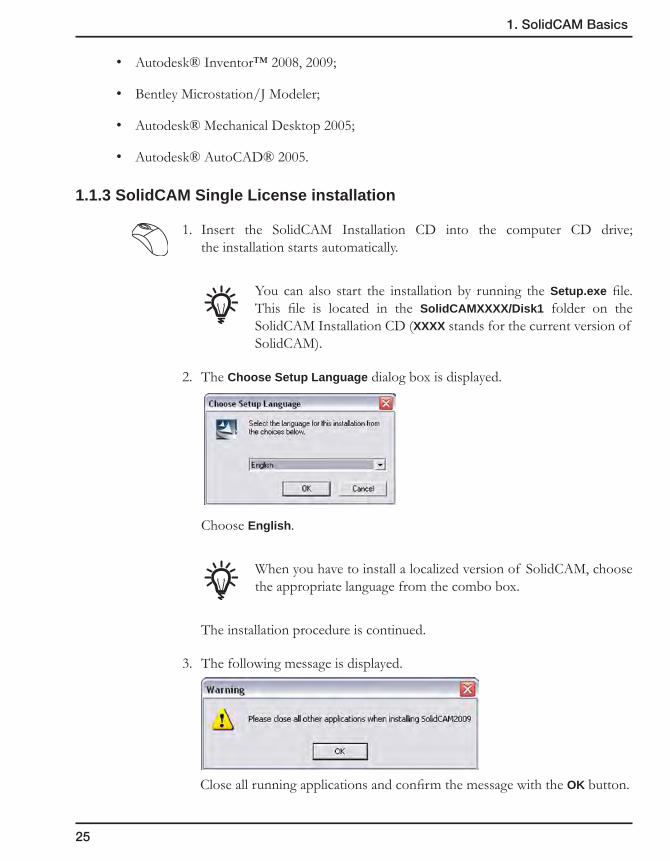
1.1.3 SolidCAM Single License installation
1. Insert the SolidCAM Installation CD into the computer CD drive; the installation starts automatically.
You can also start the installation by running the Setup.exe file. This file is located in the SolidCAMXXXX/Disk1 folder on the SolidCAM Installation CD (XXXX stands for the current version of SolidCAM).
2. The Choose Setup Language dialog box is displayed.
Choose English.
When you have to install a localized version of SolidCAM, choose the appropriate language from the combo box.
The installation procedure is continued.
3. The following message is displayed.
Close all running applications and confirm the message with the OK button.
26
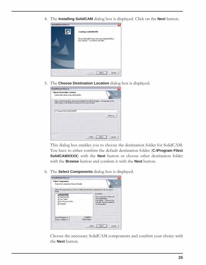
4. The Installing SolidCAM dialog box is displayed. Click on the Next button.
5. The Choose Destination Location dialog box is displayed.
This dialog box enables you to choose the destination folder for SolidCAM. You have to either confirm the default destination folder (C:\Program Files\SolidCAMXXXX) with the Next button or choose other destination folder with the Browse button and confirm it with the Next button.
6. The Select Components dialog box is displayed.
Choose the necessary SolidCAM components and confirm your choice with the Next button.

27
1. SolidCAM Basics
Make a note that Program Files component cannot be cleared.
7. The Select Program Folder dialog box is displayed.
Confirm the default Program Folder name SolidCAMXXXX with the Next button.
SolidCAM installation is continued.
8. When the installation is finished, the Choose Language dialog box is displayed.
Choose English and click on the OK button.
When you install a localized version of SolidCAM, choose the ap-propriate language from the combo box.
9. SolidCAM installs drivers for the hardware key. When the drivers are installed, the following message is displayed.
Click on the OK button.

28
10. The Connection to CAD system dialog box is displayed. This dialog box displays all CAD systems that can be used by SolidCAM.
Choose the appropriate Host CAD systems for SolidCAM.
When SolidCAM has found only one CAD system available for connection, this dialog box is not displayed.
Click on the Next button.
SolidCAM is connected to the defined CAD systems. The following message is displayed.
Click on the OK button.
11. The following dialog box is displayed.
Click on the Finish button.
The installation is finished.
29
1. SolidCAM Basics
1.1.4 SolidCAM Network License Installation
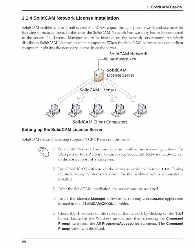
SolidCAM enables you to install several SolidCAM copies through your network and use network licensing to manage them. In this case, the SolidCAM Network hardware key has to be connected to the server. The License Manager has to be installed on the network server computer, which distributes SolidCAM Licenses to client computers. When the SolidCAM software runs on a client computer, it obtains the necessary license from the server.
Setting up the SolidCAM License Server
SolidCAM network licensing supports TCP/IP network protocol.
1. SolidCAM Network hardware keys are available in two configurations: for USB port or for LPT port. Connect your SolidCAM Network hardware key to the correct port of your server.
2. Install SolidCAM software on the server as explained in topic 1.1.3. During the installation, the necessary driver for the hardware key is automatically installed.
3. After the SolidCAM installation, the server must be restarted.
4. Install the License Manager software by running Lmsetup.exe application located in the ..\SolidCAMXXXX\Util folder.
5. Check the IP address of the server in the network by clicking on the Start button located at the Windows taskbar and then choosing the Command Prompt item from the All Programs/Accessories submenu. The Command Prompt window is displayed.
SolidCAM Client Computers
SolidCAMLicense Server
SolidCAM Networkhardware key
SolidCAM Licenses

30
6. Type the ipconfig command and confirm it with the Enter key. The IP address of the server will be displayed.
Setting SolidCAM licenses on client computers
1. Install SolidCAM on client computer as described in topic 1.1.3.
2. Copy the NethaspTCPIP.ini file located in the ..\SolidCAMXXXX\Util folder to the ..\SolidCAMXXXX\Solidcam folder.
3. Rename the copied file from NethaspTCPIP.ini to Nethasp.ini.
4. Open the renamed Nethasp.ini file in the Notepad editor. The [NH_TCPIP] section in this file contains the following string: NH_SERVER_ADDR = XX.XX.XX.XX; This parameter should define the IP address of the License Server. Type the IP address of the server instead of XX.XX.XX.XX, for example: 72.14.207.99. Save the Nethasp.ini file and close the Notepad application.
After the License Manager is installed on the SolidCAM Licensing server and SolidCAM Licenses are configured on each client computer, SolidCAM software can be run.

31
1. SolidCAM Basics
1.2 Basic Concepts
Every manufacturing project in SolidCAM contains the following data:
• CAM-Part
The CAM-Part defines the general data of the workpiece, including the model name, the Coordinate System, tool options, CNC-controller, etc.
• Geometry
By selecting Edges, Curves, Surfaces or Solids, define what and where you are going to machine. This geometry is associated with the native SolidWorks model.
• Operation
An Operation is a single machining step in SolidCAM. Technology, Tool parameters and Strategies are defined in the Operation. In short, Operation means how you want to machine.
1.3 Starting SolidCAM
To start SolidCAM, click on the SolidCAM field in the main menu of SolidWorks and choose Milling from the New submenu.
SolidCAM is started.

32
1.4 SolidCAM Interface
1.4.1 SolidCAM Manager
After the CAM-Part is loaded, the SolidCAM Manager is displayed in the left part of the screen.
The SolidCAM Manager tree is the main interface feature of SolidCAM. It displays complete information about the CAM-Part and contains the following headers:
• CAM-Partheader
This header displays the name of the current SolidCAM CAM-Part. By right-clicking on it, you can display the menu to manage your CAM-Parts. The CoordSys Manager, Stock, Target, and Settings subheaders are located under the CAM-Part header.
Double-clicking on this header displays the Milling Part Data dialog box.
For more information on CAM-Parts, please refer to Chapter 2.
CAM-Part header
Operations
Tool header
Machining Processheader
Geometries header
Operations header }
SolidWorks window
CAM Viewstoolbar
Coordinate System
MachiningSolid model
SolidCAMManager

33
1. SolidCAM Basics
• Toolheader
This header displays the name of the current Tool Table. By right-clicking on it, you can activate the menu to manage the Tool Libraries.
Double-clicking on this header displays the Part Tool Table.
For more information on Tools, please refer to Chapter 3.
• MachiningProcessheader
This header displays the name of the current Machining Process Table. By right-clicking on it, you can activate the menu to manage the MP Tables.
Double-clicking on this header displays the Current Machining Process Table.
For more information on Machining Processes, please refer to Chapter 8.
• Geometriesheader
This header displays all SolidCAM geometries not used in the operations. You can view the list of these geometries by clicking on the “+” icon near the Geometries header. You can display the geometries managing menu by right-clicking on the Geometries header. You can also open the relevant menu by right-clicking on each geometry name.
Double-clicking on a geometry name displays the selected geometry.
For more information on Geometries, please refer to Chapter 4.
• Operationsheader
This header shows you all the SolidCAM operations defined for the current CAM-Part. The operations managing menu is available by right-clicking on the Operations header. You can also open the relevant menu by right-clicking on each operation name.
Double-clicking on an operation name enables you to edit the operation parameters in the operation dialog box.
For more information on operations, please refer to Chapter 5.
Item search in SolidCAM Manager
The SolidCAM Manager search system works similarly to a regular Windows searching functionality. To activate it, click anywhere in the SolidCAM Manager area and press Ctrl+F. The Find dialog box is displayed, and you can set the parameters for searching.

34
Look in
You may look for the required items in the whole CAM-Part or only in its operations, coordinate systems or geometries taken separately.
Whole items only
Select this check box if you want to check the availability of whole items as opposed to partial output.
Match case
This check box enables you to determine the case sensitivity of the search.
Direction
You may also decide whether the search results will be displayed from bottom to top or from top to bottom of the SolidCAM Manager tree.
Find next
Click this button if you want to view the search results one by one.
Find all
Click this button if you prefer to have all of the search results to be displayed simultaneously.
General
The whole line where the sought-for word appears is highlighted in the SolidCAM Manager tree. When you close the Find dialog box, these lines remain highlighted.
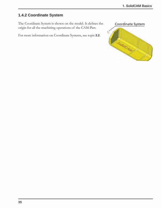
35
1. SolidCAM Basics
1.4.2 Coordinate System
The Coordinate System is shown on the model. It defines the origin for all the machining operations of the CAM-Part.
For more information on Coordinate Systems, see topic 2.2.
Coordinate System
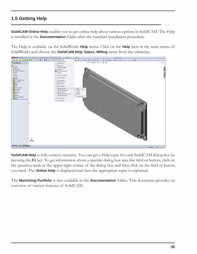
36
1.5 Getting Help
SolidCAM Online Help enables you to get online help about various options in SolidCAM. The Help is installed in the Documentation folder after the standard installation procedure.
The Help is available via the SolidWorks Help menu. Click on the Help item in the main menu of SolidWorks and choose the SolidCAM Help Topics, Milling items from the submenu.
SolidCAM Help is fully context-sensitive. You can get a Help topic for each SolidCAM dialog box by pressing the F1 key. To get information about a specific dialog box area like field or button, click on the question mark in the upper-right corner of the dialog box and then click on the field or button you need. The Online Help is displayed and then the appropriate topic is explained.
The Machining Portfolio is also available in the Documentation folder. This document provides an overview of various features of SolidCAM.

2CAM-PartAt the stage of the CAM-Part definition, you have to specify all the information relevant to the machining project or workpiece you want to manufacture. The CAM-Part folder includes all machining geometries, operation definitions and generated GCode files.
The parameters and values defined at the CAM-Part level, such as Coordinate System, Milling levels and Tools will serve as default values for separate machining operations. All specified parameters can be changed in single operations.
Starting a new Milling CAM-Part
Managing CAM-Parts
Defining the Coordinate System
Defining the Stock model
Defining the Target model
CAM-Part Documentation

38
2.1 Starting a new Milling CAM-Part
After the SolidWorks model is loaded, do the following:
1. Click on the SolidCAM item in the SolidWorks menu. The SolidCAM main menu is displayed.
2. Choose the New option from the menu to define a new CAM-Part.
3. Choose the Milling type of new CAM-Part from the submenu.
4. The New Milling Part dialog box is displayed.
When you start to program a CAM-Part, you have to decide on:
• What type of CNC-machine you are going to use (3-, 4- or 5-axis);
• Where you are going to clamp this part;
• Where your Coordinate System positions are located (on a 4- or 5-axis CNC-machine, every clamping position is represented by the Coordinate System to which all additional positionings are related).
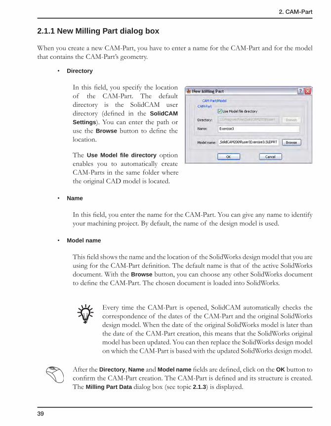
39
2. CAM-Part
2.1.1 New Milling Part dialog box
When you create a new CAM-Part, you have to enter a name for the CAM-Part and for the model that contains the CAM-Part’s geometry.
• Directory
In this field, you specify the location of the CAM-Part. The default directory is the SolidCAM user directory (defined in the SolidCAM Settings). You can enter the path or use the Browse button to define the location.
The Use Model file directory option enables you to automatically create CAM-Parts in the same folder where the original CAD model is located.
• Name
In this field, you enter the name for the CAM-Part. You can give any name to identify your machining project. By default, the name of the design model is used.
• Model name
This field shows the name and the location of the SolidWorks design model that you are using for the CAM-Part definition. The default name is that of the active SolidWorks document. With the Browse button, you can choose any other SolidWorks document to define the CAM-Part. The chosen document is loaded into SolidWorks.
Every time the CAM-Part is opened, SolidCAM automatically checks the correspondence of the dates of the CAM-Part and the original SolidWorks design model. When the date of the original SolidWorks model is later than the date of the CAM-Part creation, this means that the SolidWorks original model has been updated. You can then replace the SolidWorks design model on which the CAM-Part is based with the updated SolidWorks design model.
After the Directory, Name and Model name fields are defined, click on the OK button to confirm the CAM-Part creation. The CAM-Part is defined and its structure is created. The Milling Part Data dialog box (see topic 2.1.3) is displayed.

40
2.1.2 The structure of the CAM-Part
The Cavity CAM-Part includes the following data:
• The Cavity.prt file located in the SolidCAM User directory.
• The Cavity subdirectory containing all the data generated for the CAM-Part.
SolidCAM copies the original SolidWorks model to the Cavity subdirectory and creates a SolidWorks assembly that has the same name as the CAM-Part (Cavity.sldasm). There are two components in this assembly:
• DesignModel.sldprt – a copy of the SolidWorks model file.
• CAM.sldprt – a file that contains SolidCAM Coordinate Systems and geometry data.
SolidCAM CAM-Part uses the assembly environment of SolidWorks. This enables you to create auxiliary geometries (e.g. sketches) without making changes in the original design model. You can also insert some additional components into the assembly file such as stock model, CNC-machine table, clamping and other tooling elements.
2.1.3 Milling Part Data dialog box
In this dialog box, you specify all the information relevant to the machining project or workpiece you want to manufacture. The parameters and values defined at the CAM-Part level will later serve as default values for machining levels, etc. Naturally, all parameters can be changed in single machining operations.
Cavity.prt
Cavity.SLDASM
CAM.SLDPRT
DesignModel.SLDPRT
Cavity

41
2. CAM-Part
2.2 Coordinate System
The Coordinate System position defines the origin for all machining operations of the CAM-Part. You can create multiple CoordSys positions and specify in each machining step which CoordSys you want to use for the operation. The CAM-Part definition cannot be completed if the Coordinate System is not defined.
The Coordinate System can be defined directly on the solid model. You can define its origin location and axes orientation by selecting the model elements or by choosing the already defined SolidWorks Coordinate Systems.
2.2.1 Defining the Coordinate System (CoordSys)
Click on the Define button in the in the Coordinate System area of the Milling Part Data dialog box.
If you define the first Coordinate System in the current CAM-Part, the CoordSys dialog box (see topic 2.2.2) is displayed. This dialog box enables you to define the Coordinate Systems.
If the CoordSys that you define is not the first, the CoordSys Manager dialog box (see topic 2.3) is displayed. This dialog box enables you to manage your Coordinate Systems.
You can also define new Coordinate Systems at the later stages of operation definition by clicking on the CoordSys button available in the Geometry page of the operation dialog box (see topic 5.2.6).
Coordinate SystemOrigin
X-direction
Y-direction
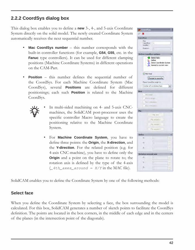
42
2.2.2 CoordSys dialog box
This dialog box enables you to define a new 3-, 4-, and 5-axis Coordinate System directly on the solid model. The newly created Coordinate System automatically receives the next sequential number.
• Mac CoordSys number – this number corresponds with the built-in controller functions (for example, G54, G55, etc. in the Fanuc type controllers). It can be used for different clamping positions (Machine Coordinate Systems) in different operations on the CAM-Part.
• Position – this number defines the sequential number of the CoordSys. For each Machine Coordinate System (Mac CoordSys), several Positions are defined for different positionings; each such Position is related to the Machine CoordSys.
• In multi-sided machining on 4- and 5-axis CNC-machines, the SolidCAM post-processor uses the specific controller Macro language to create the positioning relative to the Machine Coordinate System.
• For Machine Coordinate System, you have to define three points: the Origin, the X-direction, and the Y-direction. For the related position (e.g. for 4-axis CNC-machine), you have to define only the Origin and a point on the plane to rotate to; the rotation axis is defined by the type of the 4-axis (_4th_axes_around = X/Y in the MAC file).
SolidCAM enables you to define the Coordinate System by one of the following methods:
Select face
When you define the Coordinate System by selecting a face, the box surrounding the model is calculated. For this box, SolidCAM generates a number of sketch points to facilitate the CoordSys definition. The points are located in the box corners, in the middle of each edge and in the centers of the planes (in the intersection point of the diagonals).
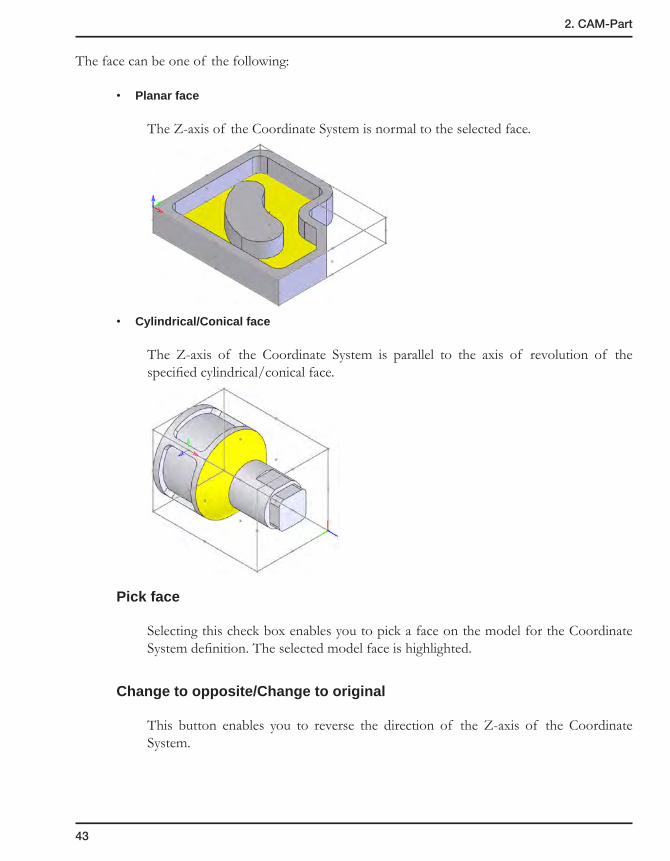
43
2. CAM-Part
The face can be one of the following:
• Planar face
The Z-axis of the Coordinate System is normal to the selected face.
• Cylindrical/Conical face
The Z-axis of the Coordinate System is parallel to the axis of revolution of the specified cylindrical/conical face.
Pick face
Selecting this check box enables you to pick a face on the model for the Coordinate System definition. The selected model face is highlighted.
Change to opposite/Change to original
This button enables you to reverse the direction of the Z-axis of the Coordinate System.

44
Place CoordSys origin to:
• Cornerofmodelbox
The upper plane of the model box is parallel to the XY-plane of the defined CoordSys. The CoordSys is located in the corner of the model box with the following coordinates (XMIN, YMIN, ZMAX).
• Centerofrevolutionface
The origin is located at the intersection of the rotation axis of the part and the face of the model box with the maximal Z-coordinate (the Z-axis is directed along the rotation axis).
• Topcenterofmodelbox
The CoordSys origin is placed in the center of the upper plane of the model, and the Z-axis of the CoordSys is normal to the selected face.
• CornerboxprojectionontheZ-leveloftheface
The CoordSys origin is placed in the corner of the generated model box on the same Z-level with the selected face, and the Z-axis of the CoordSys is normal to the selected face.
Z
CoordSysOrigin
CoordSysOrigin
CoordSysOrigin
CoordSysOrigin
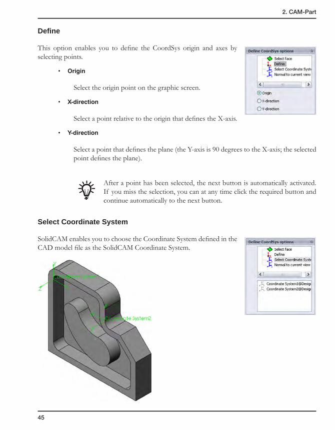
45
2. CAM-Part
Define
This option enables you to define the CoordSys origin and axes by selecting points.
• Origin
Select the origin point on the graphic screen.
• X-direction
Select a point relative to the origin that defines the X-axis.
• Y-direction
Select a point that defines the plane (the Y-axis is 90 degrees to the X-axis; the selected point defines the plane).
After a point has been selected, the next button is automatically activated. If you miss the selection, you can at any time click the required button and continue automatically to the next button.
Select Coordinate System
SolidCAM enables you to choose the Coordinate System defined in the CAD model file as the SolidCAM Coordinate System.
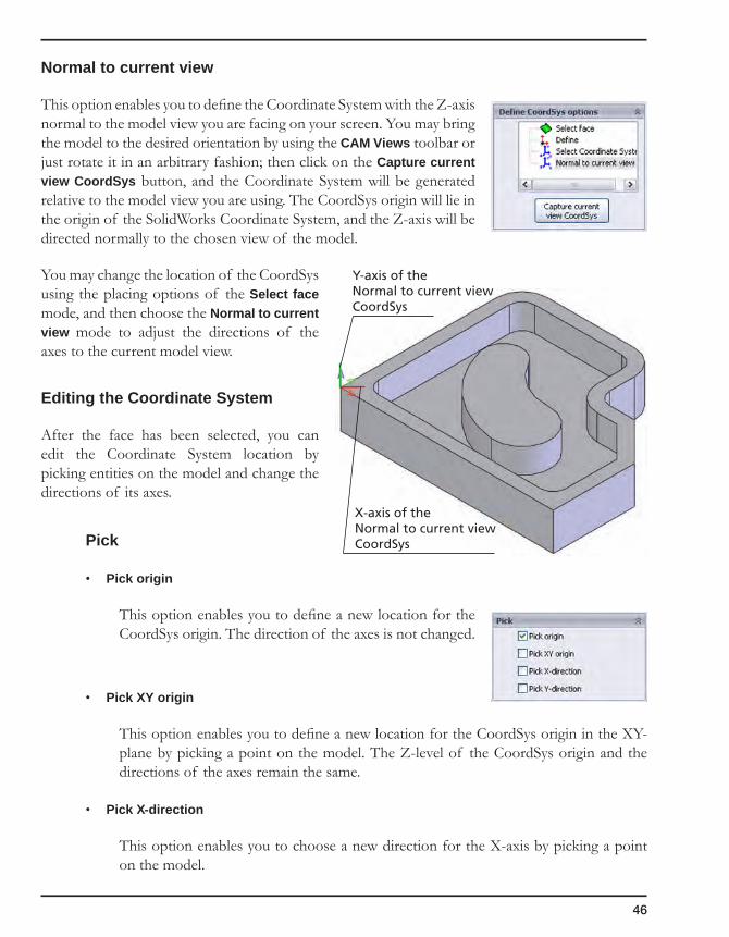
46
Normal to current view
This option enables you to define the Coordinate System with the Z-axis normal to the model view you are facing on your screen. You may bring the model to the desired orientation by using the CAM Views toolbar or just rotate it in an arbitrary fashion; then click on the Capture current view CoordSys button, and the Coordinate System will be generated relative to the model view you are using. The CoordSys origin will lie in the origin of the SolidWorks Coordinate System, and the Z-axis will be directed normally to the chosen view of the model.
You may change the location of the CoordSys using the placing options of the Select face mode, and then choose the Normal to current view mode to adjust the directions of the axes to the current model view.
Editing the Coordinate System
After the face has been selected, you can edit the Coordinate System location by picking entities on the model and change the directions of its axes.
Pick
• Pick origin
This option enables you to define a new location for the CoordSys origin. The direction of the axes is not changed.
• Pick XY origin
This option enables you to define a new location for the CoordSys origin in the XY-plane by picking a point on the model. The Z-level of the CoordSys origin and the directions of the axes remain the same.
• Pick X-direction
This option enables you to choose a new direction for the X-axis by picking a point on the model.
Y-axis of theNormal to current viewCoordSys
X-axis of theNormal to current viewCoordSys
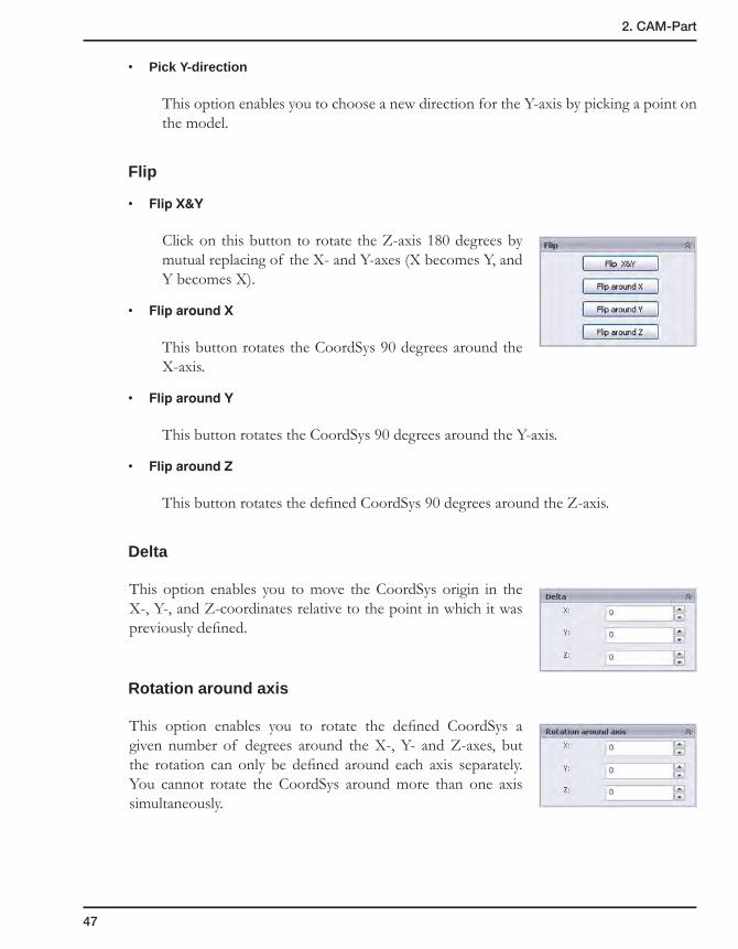
47
2. CAM-Part
• Pick Y-direction
This option enables you to choose a new direction for the Y-axis by picking a point on the model.
Flip
• FlipX&Y
Click on this button to rotate the Z-axis 180 degrees by mutual replacing of the X- and Y-axes (X becomes Y, and Y becomes X).
• FliparoundX
This button rotates the CoordSys 90 degrees around the X-axis.
• FliparoundY
This button rotates the CoordSys 90 degrees around the Y-axis.
• FliparoundZ
This button rotates the defined CoordSys 90 degrees around the Z-axis.
Delta
This option enables you to move the CoordSys origin in the X-, Y-, and Z-coordinates relative to the point in which it was previously defined.
Rotation around axis
This option enables you to rotate the defined CoordSys a given number of degrees around the X-, Y- and Z-axes, but the rotation can only be defined around each axis separately. You cannot rotate the CoordSys around more than one axis simultaneously.
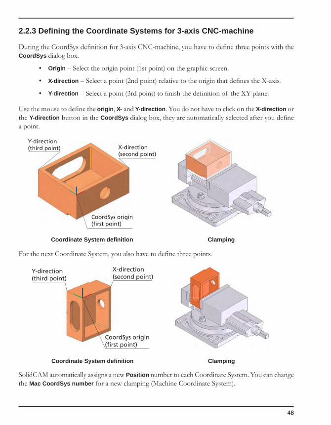
48
2.2.3 Defining the Coordinate Systems for 3-axis CNC-machine
During the CoordSys definition for 3-axis CNC-machine, you have to define three points with the CoordSys dialog box.
• Origin – Select the origin point (1st point) on the graphic screen.
• X-direction – Select a point (2nd point) relative to the origin that defines the X-axis.
• Y-direction – Select a point (3rd point) to finish the definition of the XY-plane.
Use the mouse to define the origin, X- and Y-direction. You do not have to click on the X-direction or the Y-direction button in the CoordSys dialog box, they are automatically selected after you define a point.
CoordSys origin(first point)
X-direction(second point)
Y-direction(third point)
Coordinate System definition Clamping
For the next Coordinate System, you also have to define three points.
CoordSys origin(first point)
X-direction(second point)
Y-direction(third point)
Coordinate System definition Clamping
SolidCAM automatically assigns a new Position number to each Coordinate System. You can change the Mac CoordSys number for a new clamping (Machine Coordinate System).

49
2. CAM-Part
2.2.4 Defining the Coordinate Systems for 4-axis CNC-machine
When you define the Machine Coordinate System (Mac CoordSys) for the 4-axis CNC-machine, you have to define three points with the CoordSys dialog box:
• Origin – Select the origin point (1st point) on the graphic screen.
• X-direction – Select a point (2nd point) relative to the origin that defines the X-axis.
• Y-direction – Select a point (3rd point) to finish the definition of the XY-plane.
Use the mouse to define the origin, X- and Y-direction. You do not have to click on the X-direction or the Y-direction button in the CoordSys dialog box, they are automatically selected after you define a point.
CoordSys origin(first point)
X-direction(second point)
Y-direction(third point)
Coordinate System definition Clamping
To add a new Position, you have to define only two points:
• The point for the CoordSys origin.
• The point on the plane to rotate to. If the rotation axis is X, you have to define the Y-direction. If the rotation axis is Y, you have to define the X-direction.
CoordSys origin(first point)
X-direction(determinedautomatically)Y-direction
(second point)
Coordinate System definition Clamping
SolidCAM automatically assigns the new Position number to each CoordSys. You can change the Mac CoordSys number for a new clamping (Machine Coordinate System).

50
The rotation axis is automatically defined by SolidCAM according to the Axis type (see topic 2.8.1). The Shift and Rotation around parameters are calculated automatically.
2.2.5 Defining the Coordinate Systems for 5-axis CNC-machine
When you define the Machine Coordinate System (Mac CoordSys) for the 4-axis CNC-machine, you have to define three points with the CoordSys dialog box:
• Origin – Select the origin point (1st point) on the graphic screen.
• X-direction – Select a point (2nd point) relative to the origin that defines the X-axis.
• Y-direction – Select a point (3rd point) to finish the definition of the XY-plane.
Use the mouse to define the origin, X- and Y-direction. You do not have to click on the X-direction or the Y-direction button in the CoordSys dialog box, they are automatically selected after you define a point.
CoordSys origin(first point)
X-direction(second point)Y-direction
(third point)
Coordinate System definition Clamping
To add a new CoordSys, you have to define three points.
CoordSys origin(first point)
X-direction(second point)
Y-direction(third point)
Coordinate System definition Clamping

51
2. CAM-Part
SolidCAM automatically assigns the new Position number to each CoordSys. You can change the Mac CoordSys number for a new clamping (Machine Coordinate System).
The rotation axis is defined automatically by SolidCAM according to the Axis type (see topic 2.8.1).
The Shift and Rotation around parameters are calculated automatically.
2.2.6 Coordinate System definition methods
Coordinate System definition using a sketch
In some cases, you cannot define the CoordSys origin position or the direction of the axes without adding a geometry.
Then you have to create a sketch that contains two perpendicular lines; the intersection point of the lines defines the CoordSys origin, and the lines define the X- and Y-axis directions.
Choose the origin location at the intersection point of the lines and define the axes directions.
Coordinate System definition using a stock box
SolidCAM enables you to generate the stock box surrounding the model automatically with a defined offset (see topic 2.4.1). The top stock plane is parallel to the XY-plane of the Machine Coordinate System.
Define the CoordSys in the stock box corner.
Sometimes the model is located in the assembly in such a way that you need to rotate it before using the 3D Box option in order to calculate the optimal stock.
Y-direction
CoordSysorigin
X-direction
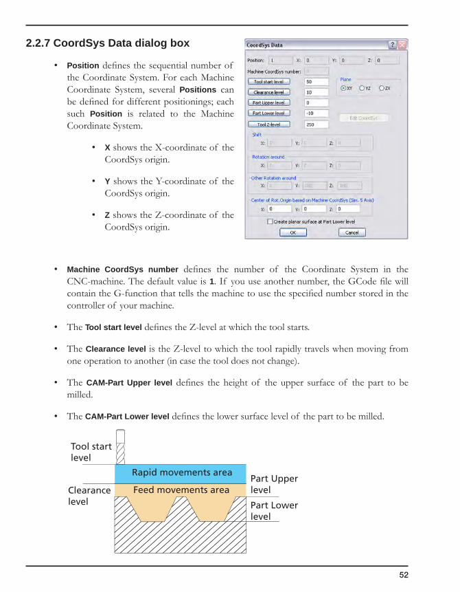
52
2.2.7 CoordSys Data dialog box
• Position defines the sequential number of the Coordinate System. For each Machine Coordinate System, several Positions can be defined for different positionings; each such Position is related to the Machine Coordinate System.
• X shows the X-coordinate of the CoordSys origin.
• Y shows the Y-coordinate of the CoordSys origin.
• Z shows the Z-coordinate of the CoordSys origin.
• Machine CoordSys number defines the number of the Coordinate System in the CNC-machine. The default value is 1. If you use another number, the GCode file will contain the G-function that tells the machine to use the specified number stored in the controller of your machine.
• The Tool start level defines the Z-level at which the tool starts.
• The Clearance level is the Z-level to which the tool rapidly travels when moving from one operation to another (in case the tool does not change).
• The CAM-Part Upper level defines the height of the upper surface of the part to be milled.
• The CAM-Part Lower level defines the lower surface level of the part to be milled.
Rapid movements area
Feed movements areaPart Upperlevel
Part Lowerlevel
Tool startlevel
Clearancelevel
53
2. CAM-Part
• The Tool Z-level is the height that the tool moves to before the rotation of the 4/5 axes to avoid collision between the tool and the workpiece. This level is related to the CoordSys position and you have to check if it is not over the limit switch of the machine. It is highly recommended to send the tool to the reference point or to a point related to the reference point.
• The Plane box defines the default work plane for the operations using this CoordSys, as it is output to the GCode program. In the SolidCAM CAM module, you must always work on the XY-plane. Some CNC-machines, however, have different axes definitions and require a GCode output with rotated XY-planes. Choose one of the following options:
• XY – the XY-plane is the work plane; the Z-axis is the depth (G17).
• YZ – the YZ-plane is the work plane; the X-axis is the depth (G18).
• ZX – the ZX-plane is the work plane; the Y-axis is the depth (G19).
This option works correctly only when your post-processor has been customized to support this function. Please contact customer support for further details.
• Shift is the distance from the Machine Coordinate System (Mac CoordSys) to the location of the Position in the coordinate system and the orientation of the Mac CoordSys.
• Rotation is the angle of rotation around the main axes X, Y and Z.
• For the first Position number related to a new Mac CoordSys number, the Shift and Rotation around parameters are always 0.
• Shift and Rotation for other Position Numbers related to the same Mac CoordSys number are determined automatically.
• The Edit CoordSys button enables you to change the CoordSys location or orientation of the axes with the CoordSys dialog box.

54
• Create planar surface at Part Lower level
This option enables you to generate a transparent planar surface at the minimal Z-level of the part so that its lower level plane is visible. This planar surface provides you the possibility to select points that do not lie on the model entities. It is suppressed by default and not visible until you unsuppress it in the FeatureManager Design tree. To unsuppress the feature, right-click on its entry under the CAM component in the FeatureManager Design tree and click on the Unsuppress button.
This option is available only when the Coordinate System has been defined by selecting a face.
2.2.8 SolidCAM Coordinate System
SolidCAM changes the model orientation by setting the model to the Machine Isometric view. This orientation is suitable for machining on a CNC machine (with the Z-axis pointing vertically upwards).
Y
XZ
Y
X
Z
SolidWorks Coordinate System SolidCAM Coordinate System
Use the CAM Views toolbar to see the SolidCAM coordinate system. These views are related to the orientation of the selected CoordSys position.

55
2. CAM-Part
2.3 CoordSys Manager
The CoordSys managing commands are available in the CoordSys Manager dialog box after the first CoordSys is defined. You can display the CoordSys Manager dialog box by clicking on the Define button in the Coordinate System area of the Milling Part Data dialog box or on the icon in the SolidCAM Manager tree.
1. Right-click on an item in the CoordSys Manager dialog box.
2. Choose a command from the menu.
Add CoordSys
This command enables you to add a new Coordinate System to the current CAM-Part.
Edit CoordSys
This command enables you to change the data of an existing Coordinate System. It also enables you to change the CoordSys position.
1. Choose the Coordinate System you want to edit.
2. The CoordSys Data dialog box is displayed showing the default Coordinate System position values. The fields and values can be changed, if necessary.
If you change the CoordSys position, you must recalculate the operations in which this CoordSys is used. You are also advised to review the simulation.
Inquire CoordSys
This command enables you to view the relevant information about a particular Coordinate System position, but you cannot edit the data.
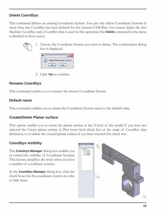
56
Delete CoordSys
This command deletes an existing Coordinate System. You can only delete Coordinate Systems if more than one CoordSys has been defined for the current CAM-Part. You cannot delete the first Machine CoordSys and a CoordSys that is used for the operation (the Delete command in the menu is disabled in these cases).
1. Choose the Coordinate System you want to delete. The confirmation dialog box is displayed.
2. Click Yes to confirm.
Rename CoordSys
This command enables you to rename the chosen Coordinate System.
Default name
This command enables you to return the Coordinate System name to the default value.
Create/Delete Planar surface
This option enables you to create the planar surface at the Z-level of the model if you have not selected the Create planar surface at Part lower level check box at the stage of CoordSys data definition, or to delete the created planar surface if you have selected this check box.
CoordSys visibility
The Coordsys Manager dialog box enables you to control the visibility of Coordinate Systems. This feature simplifies the work when you have a number of coordinate systems.
In the CoordSys Manager dialog box, clear the check boxes for the coordinate systems in order to hide them.

57
2. CAM-Part
2.4 Stock and Target Model
Stock model is the material placed on the machine before you start machining the CAM-Part.
The Stock model is used for:
• SolidVerify, SolidVerify for 3D, VerifyPlus and Machine simulation;
• For rest material calculation in 3D Milling operations.
The stock model is not automatically associated with the solid model. If the model is changed and the stock is not correct any more, you will see it in the simulation; you can then replace the defined stock with the updated one.
Note that the SolidVerify, SolidVerify for 3D and VerifyPlus simulations do not work without the Stock model defined.
Target model is the final shape of the CAM-Part after the machining.
The Target model is used for:
• 3D simulation;
• Rest material calculation;
• Gouge checking in the SolidVerify simulation.
During all machining operations, the remaining rest material is removed so that the Target model can be obtained.
Facet tolerance
The Facet tolerance parameter defines the accuracy of triangulation of the stock and target models, fixture or clamp.
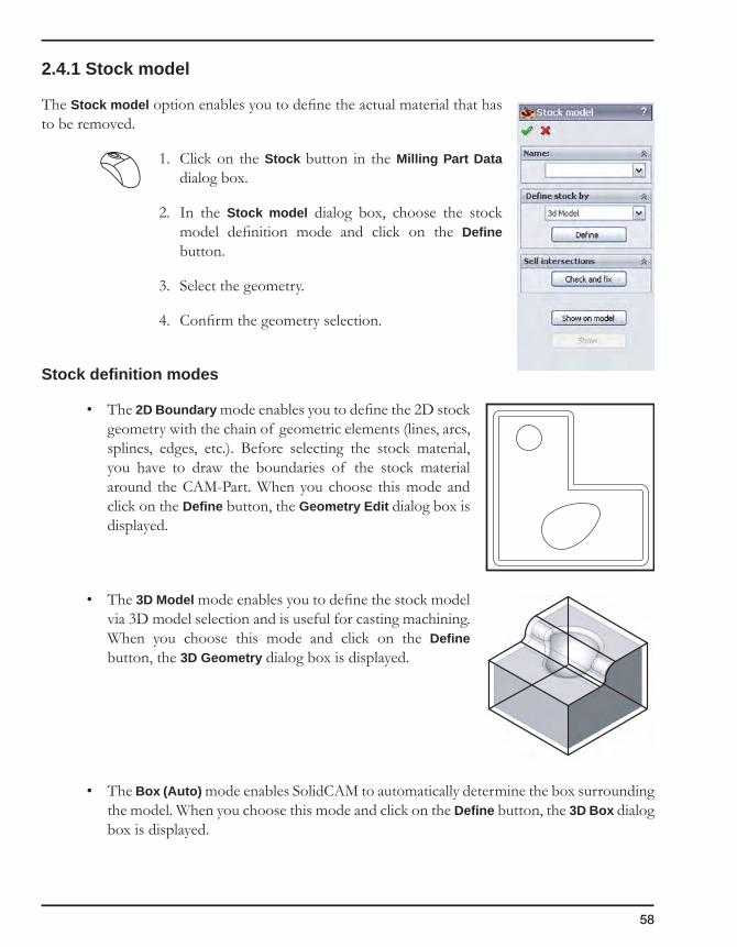
58
2.4.1 Stock model
The Stock model option enables you to define the actual material that has to be removed.
1. Click on the Stock button in the Milling Part Data dialog box.
2. In the Stock model dialog box, choose the stock model definition mode and click on the Define button.
3. Select the geometry.
4. Confirm the geometry selection.
Stock definition modes
• The 2D Boundary mode enables you to define the 2D stock geometry with the chain of geometric elements (lines, arcs, splines, edges, etc.). Before selecting the stock material, you have to draw the boundaries of the stock material around the CAM-Part. When you choose this mode and click on the Define button, the Geometry Edit dialog box is displayed.
• The 3D Model mode enables you to define the stock model via 3D model selection and is useful for casting machining. When you choose this mode and click on the Define button, the 3D Geometry dialog box is displayed.
• The Box (Auto) mode enables SolidCAM to automatically determine the box surrounding the model. When you choose this mode and click on the Define button, the 3D Box dialog box is displayed.

59
2. CAM-Part
3D Box dialog box
This dialog box is used to select a 3D model to create a 3D box around the model.
• The Name option enables you to define the name for the stock model. The default geometry name is assigned automatically and can be edited if necessary.
• The Type option enables you to choose the type of model elements that will be selected: Solids (solid models), Surfaces, or Both.
• The Expand box at option enables you to define how much access stock material you have in each direction of the stock material.
• The CAD selection button enables you to pick the model with the Host CAD tools.
• The Add box to CAD model button enables you to add the stock box to the CAD model.
• The STL file mode enables you to define the stock model based on a STL file that exists in your system. When you choose this mode and click on the Define button, the Choose STL dialog box is displayed. This dialog box enables you to choose the STL file for the stock definition.
Choose STL dialog box
• The Name option enables you to define the name of the STL stock geometry. The default geometry name is assigned automatically and can be edited if necessary.
• The STL File section shows the path to the STL file chosen for the stock geometry definition.
• The Browse button enables you to display the browser dialog box from which you will choose the required STL file.
• The Show button enables you to display the defined stock in the Rest material window of SolidCAM (see topic 2.4.3).
• The Show on model button enables you to display the defined stock in the SolidCAM graphic area applied to the solid model (see topic 2.4.3).

60
2.4.2 Target model
The Target model option enables you to define the final part after machining.
1. Click on the Target button in the Milling Part Data dialog box.
2. In the Target model dialog box, click on the Define 3D Model button to start the geometry selection.
3. Select the geometry with the 3D Geometry dialog box (see topic 4.3.1).
4. Confirm the Target model definition with the button.
In future operations, you can use the Target model as a geometry.
2.4.3 Common controls for Stock model and Target model dialog boxes
Name
In this field, you can see the stock or target model name and choose the model from the previously defined 3D geometries.
Show
Click on this button to show the Stock or Target model in the Rest material window of SolidCAM.
Target model Stock model
To control the quality of the Stock and Target models visualization, you can change the Facet tolerance in the Milling Part Data dialog box. The recommended value is 0.01 mm. A smaller tolerance will improve the quality and reduce the visualization speed.

61
2. CAM-Part
Show on model
Click on this button to see the selected Target model in the Host CAD window.
Target model Stock model
Self-intersections
The Check and fix button in the Self-intersections section enables you to check the model for self-intersections and fix them if they are found.
When self-intersections are detected, the following message is displayed:
Confirm it with the Yes button to fix the self-intersections.
Note that the process of self-intersection fixing can take a long time to complete, depending on the complexity of the model.
For more information on self-intersections, see topic 10.6.6.
2.4.4 Associativity of Stock and Target models
SolidCAM enables you to keep the associativity between Stock/Target model and the SolidWorks model. When the SolidWorks model is updated, SolidCAM enables you to check the compliance of the Stock and Target model geometry to the updated SolidWorks model. If the SolidCAM geometry is not synchronized with the SolidWorks model, you can synchronize it.
The Check synchronization command enables you to check the synchronization status of the Stock/Target model geometry relative to the SolidWorks model.
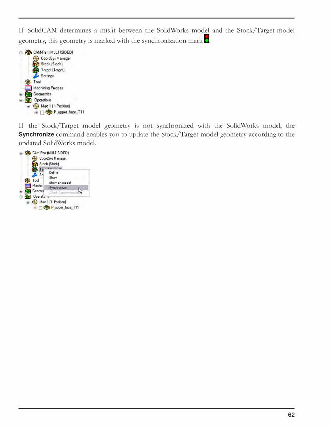
62
If SolidCAM determines a misfit between the SolidWorks model and the Stock/Target model geometry, this geometry is marked with the synchronization mark .
If the Stock/Target model geometry is not synchronized with the SolidWorks model, the Synchronize command enables you to update the Stock/Target model geometry according to the updated SolidWorks model.
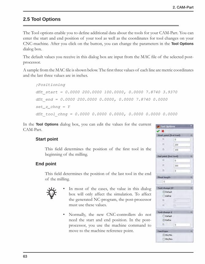
63
2. CAM-Part
2.5 Tool Options
The Tool options enable you to define additional data about the tools for your CAM-Part. You can enter the start and end position of your tool as well as the coordinates for tool changes on your CNC-machine. After you click on the button, you can change the parameters in the Tool Options dialog box.
The default values you receive in this dialog box are input from the MAC file of the selected post-processor.
A sample from the MAC file is shown below. The first three values of each line are metric coordinates and the last three values are in inches.
;Positioning
dflt_start = 0.0000 200.0000 100.0000, 0.0000 7.8740 3.9370
dflt_end = 0.0000 200.0000 0.0000, 0.0000 7.8740 0.0000
set_z_chng = Y
dflt_tool_chng = 0.0000 0.0000 0.0000, 0.0000 0.0000 0.0000
In the Tool Options dialog box, you can edit the values for the current CAM-Part.
Start point
This field determines the position of the first tool in the beginning of the milling.
End point
This field determines the position of the last tool in the end of the milling.
• In most of the cases, the value in this dialog box will only affect the simulation. To affect the generated NC-program, the post-processor must use these values.
• Normally, the new CNC-controllers do not need the start and end position. In the post-processor, you use the machine command to move to the machine reference point.

64
Tool change XY
This field defines the XY-coordinates of the tool change position. There are two options:
• DefaultasinMACfile
The XY-coordinates of the tool change position are defined by the end point of the operation that was executed before the tool change.
• Define
The XY-coordinates of the tool change position are defined by the user.
Tool change Z
This field defines the Z-coordinate of the tool change position. There are two options:
• DefaultasinMACfile
The Z-level where tool changes are performed is automatically read from the Tool start plane specified in the CoordSys Data dialog box (default input from MAC file).
• Define
The Z-coordinate of the tool change position is defined by the user.
Feed type
Defines the default type of feed used for the tool of this CAM-Part. There are two options:
• Mm/Min – Millimeters per Minute;
• Mm/Rev – Millimeters per Revolution.

65
2. CAM-Part
2.6 Mac Options
If the MAC file of your post-processor has extra fields (parameters) defined, they can be accessed through this field. In the Machine Options List dialog box, you can enter unique information related to the machine controller you have selected.
• In case of Numeric or Integer field type, the Numeric/Integer Value dialog box is displayed and you are prompted to enter a value.
• In case of Logical field type, the Logical Value dialog box is displayed and you are prompted to choose between Yes and No.
Refer to the GPPTool manual for additional information.
2.7 Work Material
This option enables you to define the work material. Choose the work material from the list.
The Work material field enables you to get Speed/Feed Defaults (see topic 3.11) based on the work and tool materials that you are using. If you choose the None option, the system will offer you the internal standard value spin of 1000 rpm and the default feed for X, Y movement of 100 mm/min.

66
2.8 CNC-Controller and Axis Type
Select the CNC-machine controller. Click on the arrow next to the controller field to display the list of post-processors installed on your system.
2.8.1 Axis type
This field displays the CNC-controller type. This field cannot be edited; it is defined in the post-processor file.
The axis type can be one of the following:
• 3axis;
• 4_axis_around_Xor4_axis_around_Y;
• 5axis.
The axis type defines the Coordinate System definition method:
3 axis
In this type of machine, every side requires a new clamping (new Machine CoordSys). For each Mac CoordSys, you have to define the origin position, the X-axis direction and the Y-axis direction.
4 axis
• 4_axis_around_X
This type is used for vertical machines with the 4th axis on the table along the X-axis.
When defining the Machine CoordSys, you have to define the origin position, the X-axis direction and the Y-axis direction. For all additional positionings, based on this clamping, you have to define the origin position and the Y-axis direction only (the angle); the X-axis direction is determined automatically by the X-axis direction of the Machine CoordSys.

67
2. CAM-Part
• 4_axis_around_Y
This type is used for horizontal machines with the 4th axis along the Y-axis.
When defining the Machine CoordSys, you have to define the origin position, the X-axis direction and the Y-axis direction. For all additional positionings, based on this clamping, you have to define the origin position and the X-axis direction only (the angle); the Y-axis direction is determined automatically by the Y-axis direction of the Machine CoordSys.
5 axis
This type is used for 5-axis CNC-machines. For the Machine CoordSys, you have to define the origin position, the X-axis direction and the Y-axis direction. All additional positioning is related to this Machine CoordSys.
Take care of the machine limitations (angles or undercuts). A message on the limit can be generated only during the GCode generation.
In the definition process, it is not necessary to consider the kinematics of the CNC-machine. This is done in the last step when you generate the NC-program.
• A CAM-Part created for a CNC-controller of 3-axis type cannot be converted to 4- or 5- axis type.
• A CAM-Part created for the CNC-controller of 4-axis type can be converted to 3-axis type.
• A CAM-Part created for the CNC-controller of 5-axis type can be converted to 3-axis type.

68
2.9 Default GCode numbers
The fields in this area are displayed according to a parameter defined in the MAC file.
; Program numbers
get_prog_num = N or Y
get_proc_num = N or Y
If N – the field is not displayed.
If Y – the field is displayed.
get_prog_num = Y
get_proc_num = N
Program number
This field enables you to define the number of the main program that will be generated in the output NC-program.
This field has ranges that are controlled from the MAC file parameters.
prog_num_min = 1
prog_num_max = 9999
prog_num_dflt = 5000

69
2. CAM-Part
In this case, the default number is 5000. You can change this value and type a number between 1 and 9999. Typing any number beyond this range is followed with the message:
Subroutine number
In this field, you can define the number of the first subroutine in the generated output NC-program.
This field has ranges that are controlled from the MAC file parameters.
proc_num_min = 1000
proc_num_max = 5000
proc_num_dflt = 1000
In this case, the default number is 1000. You can change this value and type a number between 1000 and 5000. Typing any number beyond this range is followed with the same message as above.
In some machines (for example, Fanuc), the main program number and subroutine number cannot be the same. SolidCAM does not warn you about this problem. In order to prevent this situation, you can set the main program range to 1 – 1000 and the subroutines range to 1001 to 9999 in the MAC file.
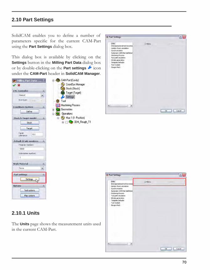
70
2.10 Part Settings
SolidCAM enables you to define a number of parameters specific for the current CAM-Part using the Part Settings dialog box.
This dialog box is available by clicking on the Settings button in the Milling Part Data dialog box or by double-clicking on the Part settings icon under the CAM-Part header in SolidCAM Manager.
2.10.1 Units
The Units page shows the measurement units used in the current CAM-Part.
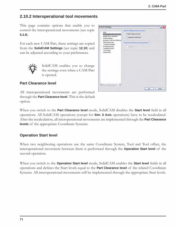
71
2. CAM-Part
2.10.2 Interoperational tool movements
This page contains options that enable you to control the interoperational movements (see topic 5.2.8).
For each new CAM-Part, these settings are copied from the SolidCAM Settings (see topic 12.10) and can be adjusted according to your preferences.
SolidCAM enables you to change the settings even when a CAM-Part is opened.
Part Clearance level
All interoperational movements are performed through the Part Clearance level. This is the default option.
When you switch to the Part Clearance level mode, SolidCAM disables the Start level field in all operations. All SolidCAM operations (except for Sim. 5 Axis operations) have to be recalculated. After the recalculation, all interoperational movements are implemented through the Part Clearance levels of the appropriate Coordinate Systems.
Operation Start level
When two neighboring operations use the same Coordinate System, Tool and Tool offset, the interoperational movement between them is performed through the Operation Start level of the second operation.
When you switch to the Operation Start level mode, SolidCAM enables the Start level fields in all operations and defines the Start levels equal to the Part Clearance level of the related Coordinate Systems. All interoperational movements will be implemented through the appropriate Start levels.
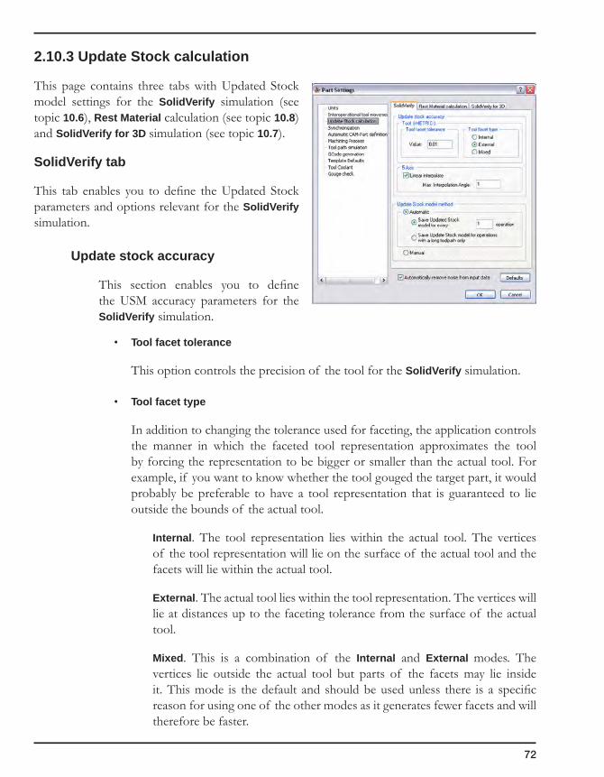
72
2.10.3 Update Stock calculation
This page contains three tabs with Updated Stock model settings for the SolidVerify simulation (see topic 10.6), Rest Material calculation (see topic 10.8) and SolidVerify for 3D simulation (see topic 10.7).
SolidVerify tab
This tab enables you to define the Updated Stock parameters and options relevant for the SolidVerify simulation.
Update stock accuracy
This section enables you to define the USM accuracy parameters for the SolidVerify simulation.
• Tool facet tolerance
This option controls the precision of the tool for the SolidVerify simulation.
• Tool facet type
In addition to changing the tolerance used for faceting, the application controls the manner in which the faceted tool representation approximates the tool by forcing the representation to be bigger or smaller than the actual tool. For example, if you want to know whether the tool gouged the target part, it would probably be preferable to have a tool representation that is guaranteed to lie outside the bounds of the actual tool.
Internal. The tool representation lies within the actual tool. The vertices of the tool representation will lie on the surface of the actual tool and the facets will lie within the actual tool.
External. The actual tool lies within the tool representation. The vertices will lie at distances up to the faceting tolerance from the surface of the actual tool.
Mixed. This is a combination of the Internal and External modes. The vertices lie outside the actual tool but parts of the facets may lie inside it. This mode is the default and should be used unless there is a specific reason for using one of the other modes as it generates fewer facets and will therefore be faster.

73
2. CAM-Part
5 Axis
The Linear interpolate option enables you to perform the linear interpolation of 5-axis tool movement. The Max. interpolation angle value defines the angular tolerance for the interpolation.
Update stock model method
This section enables you to choose the method of Stock model updating.
• Automatic
Save updated stock model for every specified number of operations: SolidCAM automatically calculates and saves the Updated Stock model. The specified number enables you to define the quantity of intermediate USM files. For example:
• if the specified number is 1, SolidCAM automatically saves intermediate USM files for each operation;
• if the specified number is 2, SolidCAM automatically saves intermediate USM files for all even operations (2nd, 4th, 6th, etc.);
• if the specified number is 0, SolidCAM does not save intermediate USM files.
Save updated stock model for operations with a long tool path only: SolidCAM automatically estimates the time required for simulation of operations and saves the updated stock for those operations whose tool path is considered too long.
• Manual
SolidCAM enables you to manually save the updated stock model for a specific operation during the SolidVerify simulation. The simulation of the next operations can be performed on the updated stock model. Further 3D Milling operations can also use the saved USM for the cutting in Rest material areas.
Automatically remove noise from input data
During the faceting of Stock and Target models, the coordinates of facets generated by SolidCAM are often calculated as numbers of the float type with many digits after the point. These numbers cause problems during the SolidVerify simulation, such as self-intersections and gaps in model. The Automatically remove noise from input data check box enables you to use a smart rounding algorithm that removes the noise in facet coordinates so that the model is displayed properly.
Note that the process of removing the noise may take a long time to complete.

74
Rest Material calculation tab
This tab enables you to define the Updated Stock parameters and options used for the Rest material calculation in 3D Milling operations.
Update stock accuracy
This section enables you to define the USM accuracy parameters for the Rest material calculation.
5 Axis
The Linear interpolate option enables you to perform the linear interpolation of 5-axis tool movement. The Max. interpolation angle value defines the angular tolerance for the interpolation.
Current Stock model method
This section displays the method of Stock model updating used for the Rest Material calculation. The setting of this section can be changed in the SolidVerify tab.
SolidVerify for 3D tab
This tab enables you to define the Updated Stock parameters and options relevant for the SolidVerify for 3D simulation.
The Updated Stock calculation parameters defined for this type of simulation are similar to those defined for SolidVerify. Since in this simulation mode analytical surfaces are used instead of facet models used for SolidVerify, the Updated Stock model accuracy section is not relevant.
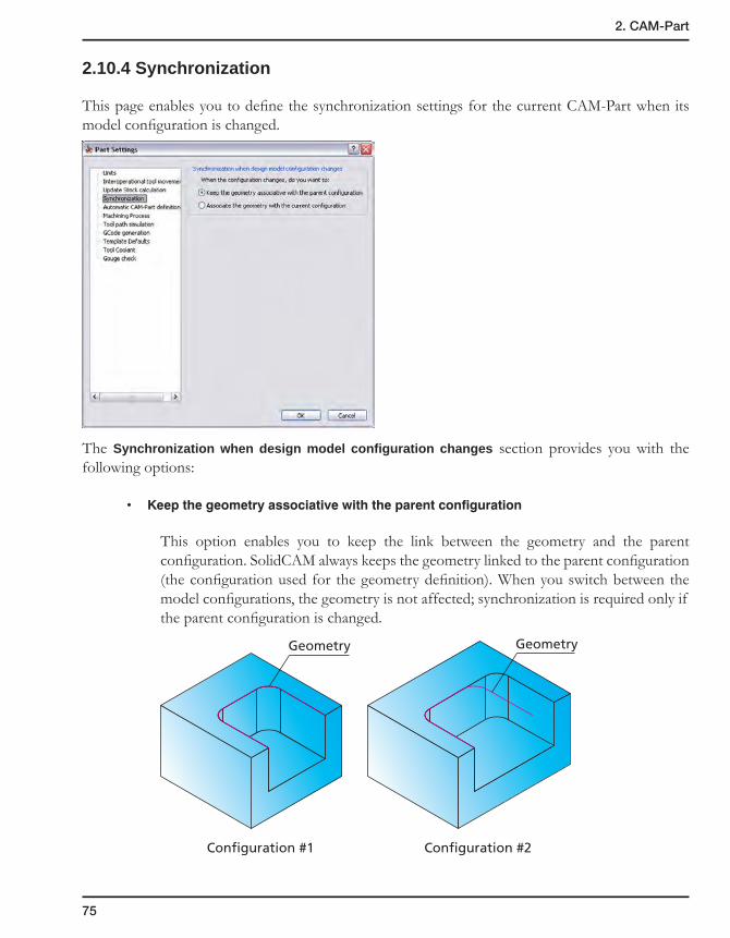
75
2. CAM-Part
2.10.4 Synchronization
This page enables you to define the synchronization settings for the current CAM-Part when its model configuration is changed.
The Synchronization when design model configuration changes section provides you with the following options:
• Keepthegeometryassociativewiththeparentconfiguration
This option enables you to keep the link between the geometry and the parent configuration. SolidCAM always keeps the geometry linked to the parent configuration (the configuration used for the geometry definition). When you switch between the model configurations, the geometry is not affected; synchronization is required only if the parent configuration is changed.
Geometry
Configuration #1
Geometry
Configuration #2
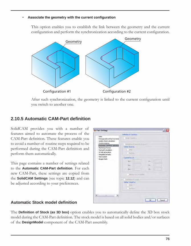
76
• Associatethegeometrywiththecurrentconfiguration
This option enables you to establish the link between the geometry and the current configuration and perform the synchronization according to the current configuration.
After such synchronization, the geometry is linked to the current configuration until you switch to another one.
2.10.5 Automatic CAM-Part definition
SolidCAM provides you with a number of features aimed to automate the process of the CAM-Part definition. These features enable you to avoid a number of routine steps required to be performed during the CAM-Part definition and perform them automatically.
This page contains a number of settings related to the Automatic CAM-Part definition. For each new CAM-Part, these settings are copied from the SolidCAM Settings (see topic 12.12) and can be adjusted according to your preferences.
Automatic Stock model definition
The Definition of Stock (as 3D box) option enables you to automatically define the 3D box stock model during the CAM-Part definition. The stock model is based on all solid bodies and/or surfaces of the DesignModel component of the CAM-Part assembly.
Geometry
Configuration #1
Geometry
Configuration #2
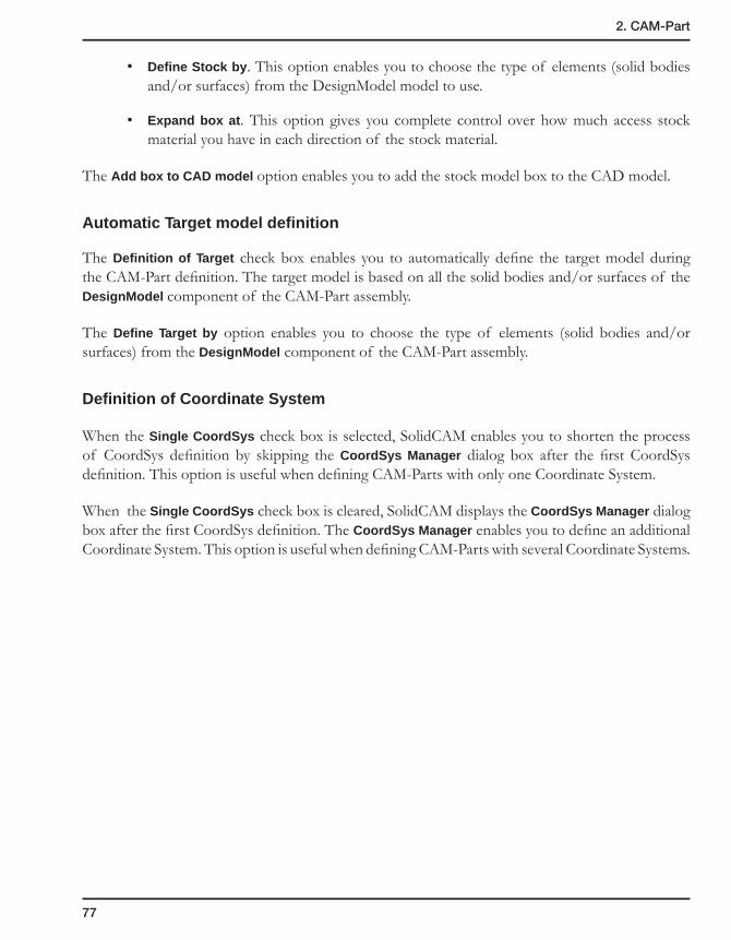
77
2. CAM-Part
• Define Stock by. This option enables you to choose the type of elements (solid bodies and/or surfaces) from the DesignModel model to use.
• Expand box at. This option gives you complete control over how much access stock material you have in each direction of the stock material.
The Add box to CAD model option enables you to add the stock model box to the CAD model.
Automatic Target model definition
The Definition of Target check box enables you to automatically define the target model during the CAM-Part definition. The target model is based on all the solid bodies and/or surfaces of the DesignModel component of the CAM-Part assembly.
The Define Target by option enables you to choose the type of elements (solid bodies and/or surfaces) from the DesignModel component of the CAM-Part assembly.
Definition of Coordinate System
When the Single CoordSys check box is selected, SolidCAM enables you to shorten the process of CoordSys definition by skipping the CoordSys Manager dialog box after the first CoordSys definition. This option is useful when defining CAM-Parts with only one Coordinate System.
When the Single CoordSys check box is cleared, SolidCAM displays the CoordSys Manager dialog box after the first CoordSys definition. The CoordSys Manager enables you to define an additional Coordinate System. This option is useful when defining CAM-Parts with several Coordinate Systems.

78
2.10.6 Machining Process
On MP insertion (for milling only)
Select the Perform auto calculation check box in case you want the operations to be calculated automatically after the Machining Process is inserted into the CAM-Part.
If you select the Ask before calculation check box, the message that enables you to confirm the calculation is displayed. If this check box is cleared, the calculation starts without prior notice.
Operation name in SolidCAM Manager
The setting of this field defines how the operation names appear in SolidCAM Manager when a Machining Process Table is loaded and a Machining Process is added to the CAM-Part.
When the Show group name check box is selected, the operation names are preceded with the names of the operation groups and default sets defined in Machining Process Table Manager.
Prismatic part_20-6_finish_wall
Operationgroup name
Default set name
Operationname

79
2. CAM-Part
When this check box is not selected, only the operation names appear in the SolidCAM Manager tree.
2.10.7 Tool path simulation
SolidCAM enables you to define the default simulation mode.
• Use Host CAD simulation as default
When this option is chosen, the Host CAD simulation mode is used as default for each new simulation session.
• Remember last simulation option
When this option is chosen, simulation starts in the last used mode.

80
2.10.8 GCode generation
This page enables you to define the parameters of the GCode generation.
The Save GCode files box offers three options to define the parameters related to saving of GCode files:
In the CAM-Part directory
SolidCAM saves the generated GCode files in the CAM-Part directory. The path to this directory is displayed in the read-only field. This option is used by default.
According to the MAC file
SolidCAM saves the generated GCode files according to the parameters defined in the MAC file. The path to the directory that appears in the MAC file is displayed in the read-only field.
In the GCode directory
SolidCAM saves the generated GCode files in the specified GCode folder location. When the GCode generation is started, SolidCAM creates a new folder with the CAM-Part name in the specified GCode directory and saves the GCode files there. If this folder already exists, SolidCAM uses it for the GCode output.
This group box enables you to define the path for the GCode directory. You can enter the path or click on the Browse button and choose the destination folder using the Browse For Folder dialog box.
If you have entered the path to a non-existing folder, the following message is displayed after the confirmation of the Part Settings dialog box:

81
2. CAM-Part
The Create button enables you to create the folder that will be used for GCode directory in the specified location. The Browse button displays the browser dialog box that enables you to choose another location that will be used for the GCode directory.
If the new folder cannot be created, the following message is displayed:
If the chosen folder has the read-only attribute, the following message is displayed after the confirmation of the Browse dialog box or the Part Settings dialog box:
By default, the GCode directory location is not defined. You have to specify it when you choose the In the GCode directory option for the first time.
Create subfolders for split GCode files
When split marks are detected in SolidCAM Manager during the GCode generation for the entire CAM-Part, SolidCAM creates a number of GCode segment files. Each such GCode segment file is created for one or several operations enclosed by split marks. These files are named with the CAM-Part name followed by the “-” sign and the order number of a split segment.
Split marks are ignored in case of GCode generation for several operations.
With the In the GCode directory option, SolidCAM creates separate CAM-Part GCode folders in the specified folder location.
When the Create subfolders for split GCode files check box is selected, SolidCAM creates a separate folder for each GCode segment file and saves the GCode segments files there. The folder is created in the GCode folder of the CAM-Part in the specified GCode folder location. The name of the folder is the same as the GCode segment file name.

82
When the Create subfolders for split GCode files check box is not selected, SolidCAM generates all the GCode segment files directly into the GCode folder of the CAM-Part in the specified GCode folder location.
By default, the Create subfolders for split GCode files option is not selected.
Create separate folders for each CAM-Part
When this check box is selected, SolidCAM creates a folder for each CAM-Part and saves the GCode file there. Otherwise, the GCode files for all CAM-Parts are generated into the GCode directory.
Additional control of GCode
When the Customize GCode file name check box is selected, you can alter the GCode file name and location. When you click one of the GCode generation commands, the Windows-style Save GCode browser is displayed with the default CAM-Part name and location that might be edited.
All the GCode files previously generated for the current CAM-Part remain in the specified folder.
When this check box is not selected, the GCode is generated and automatically saved in the defined location.
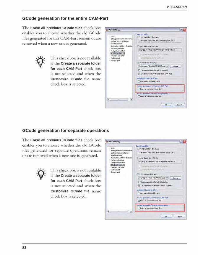
83
2. CAM-Part
GCode generation for the entire CAM-Part
The Erase all previous GCode files check box enables you to choose whether the old GCode files generated for this CAM-Part remain or are removed when a new one is generated.
This check box is not available if the Create a separate folder for each CAM-Part check box is not selected and when the Customize GCode file name check box is selected.
GCode generation for separate operations
The Erase all previous GCode files check box enables you to choose whether the old GCode files generated for separate operations remain or are removed when a new one is generated.
This check box is not available if the Create a separate folder for each CAM-Part check box is not selected and when the Customize GCode file name check box is selected.

84
2.10.9 Template defaults
This page enables you define the default location of the operation templates and to specify the default templates used for each new operation of the loaded CAM-Part.
When a new CAM-Part is being created and defined, the Part settings for Templates and Defaults are copied from the SolidCAM Settings.
SolidCAM Template Directory
This section enables you to define the default location for SolidCAM templates. You can define the path by entering it in the box or by clicking on the Browse button and choosing the location. In case the chosen folder does not exist, the error message is displayed.
• The Create button enables you to create the folder with the specified location and set it as the SolidCAM Template directory.
• The Browse button displays the browser dialog box that enables you to choose another location for the SolidCAM Templates directory.
The default Templates directory location is ..\Tables\Metric\Templates for Metric units and ..\Tables\Inch\Templates for Inch units.
Operation default templates
This section enables you to assign a default template to each operation type. It contains the following tabs:
• The 2.5D Milling tab lists the templates of 2.5D Milling operations.
• The 3D Milling tab lists the templates of 3D Milling operations.
• The HSM and HSS tabs list the templates of HSM and HSS operations.
• The Sim. 4 Axis and Sim. 5 Axis tabs list the templates of Sim. 4 Axis and Sim. 5 Axis operations.
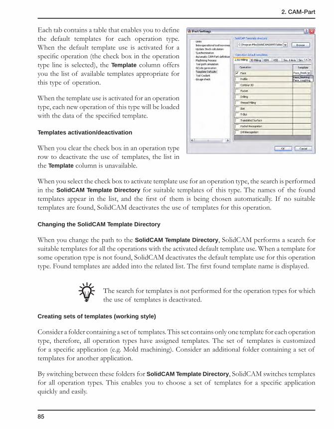
85
2. CAM-Part
Each tab contains a table that enables you to define the default templates for each operation type. When the default template use is activated for a specific operation (the check box in the operation type line is selected), the Template column offers you the list of available templates appropriate for this type of operation.
When the template use is activated for an operation type, each new operation of this type will be loaded with the data of the specified template.
Templates activation/deactivation
When you clear the check box in an operation type row to deactivate the use of templates, the list in the Template column is unavailable.
When you select the check box to activate template use for an operation type, the search is performed in the SolidCAM Template Directory for suitable templates of this type. The names of the found templates appear in the list, and the first of them is being chosen automatically. If no suitable templates are found, SolidCAM deactivates the use of templates for this operation.
Changing the SolidCAM Template Directory
When you change the path to the SolidCAM Template Directory, SolidCAM performs a search for suitable templates for all the operations with the activated default template use. When a template for some operation type is not found, SolidCAM deactivates the default template use for this operation type. Found templates are added into the related list. The first found template name is displayed.
The search for templates is not performed for the operation types for which the use of templates is deactivated.
Creating sets of templates (working style)
Consider a folder containing a set of templates. This set contains only one template for each operation type, therefore, all operation types have assigned templates. The set of templates is customized for a specific application (e.g. Mold machining). Consider an additional folder containing a set of templates for another application.
By switching between these folders for SolidCAM Template Directory, SolidCAM switches templates for all operation types. This enables you to choose a set of templates for a specific application quickly and easily.
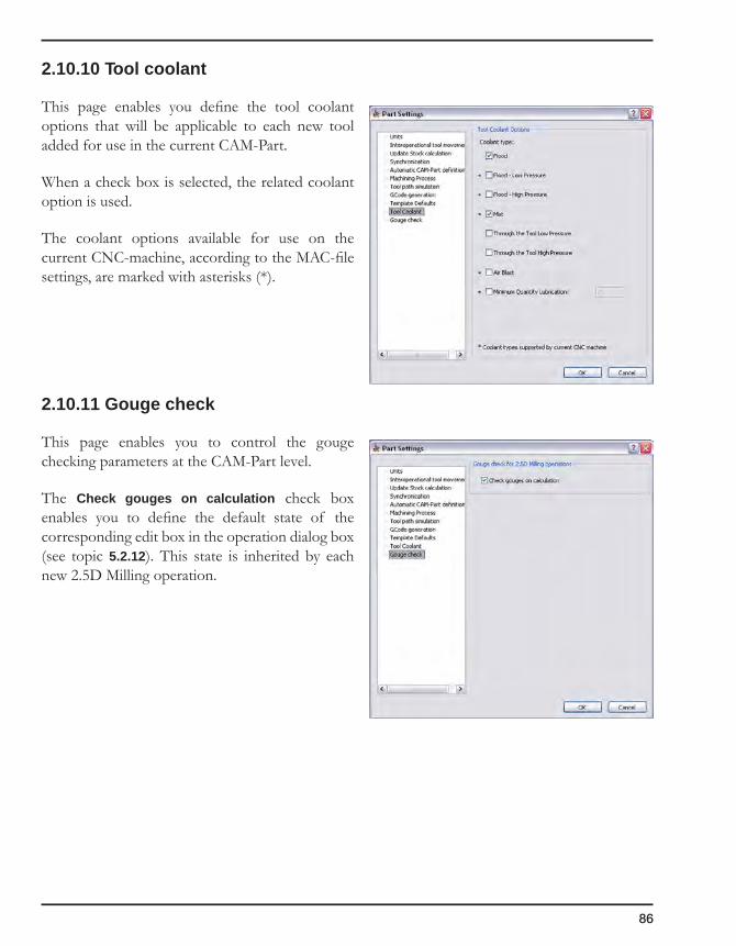
86
2.10.10 Tool coolant
This page enables you define the tool coolant options that will be applicable to each new tool added for use in the current CAM-Part.
When a check box is selected, the related coolant option is used.
The coolant options available for use on the current CNC-machine, according to the MAC-file settings, are marked with asterisks (*).
2.10.11 Gouge check
This page enables you to control the gouge checking parameters at the CAM-Part level.
The Check gouges on calculation check box enables you to define the default state of the corresponding edit box in the operation dialog box (see topic 5.2.12). This state is inherited by each new 2.5D Milling operation.
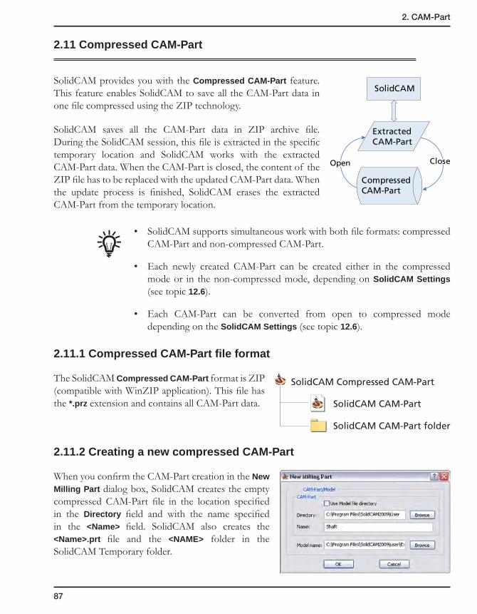
87
2. CAM-Part
2.11 Compressed CAM-Part
SolidCAM provides you with the Compressed CAM-Part feature. This feature enables SolidCAM to save all the CAM-Part data in one file compressed using the ZIP technology.
SolidCAM saves all the CAM-Part data in ZIP archive file. During the SolidCAM session, this file is extracted in the specific temporary location and SolidCAM works with the extracted CAM-Part data. When the CAM-Part is closed, the content of the ZIP file has to be replaced with the updated CAM-Part data. When the update process is finished, SolidCAM erases the extracted CAM-Part from the temporary location.
• SolidCAM supports simultaneous work with both file formats: compressed CAM-Part and non-compressed CAM-Part.
• Each newly created CAM-Part can be created either in the compressed mode or in the non-compressed mode, depending on SolidCAM Settings (see topic 12.6).
• Each CAM-Part can be converted from open to compressed mode depending on the SolidCAM Settings (see topic 12.6).
2.11.1 Compressed CAM-Part file format
The SolidCAM Compressed CAM-Part format is ZIP (compatible with WinZIP application). This file has the *.prz extension and contains all CAM-Part data.
2.11.2 Creating a new compressed CAM-Part
When you confirm the CAM-Part creation in the New Milling Part dialog box, SolidCAM creates the empty compressed CAM-Part file in the location specified in the Directory field and with the name specified in the <Name> field. SolidCAM also creates the <Name>.prt file and the <NAME> folder in the SolidCAM Temporary folder.
SolidCAM
Open Close
ExtractedCAM-Part
CompressedCAM-Part
SolidCAM CAM-Part
SolidCAM Compressed CAM-Part
SolidCAM CAM-Part folder
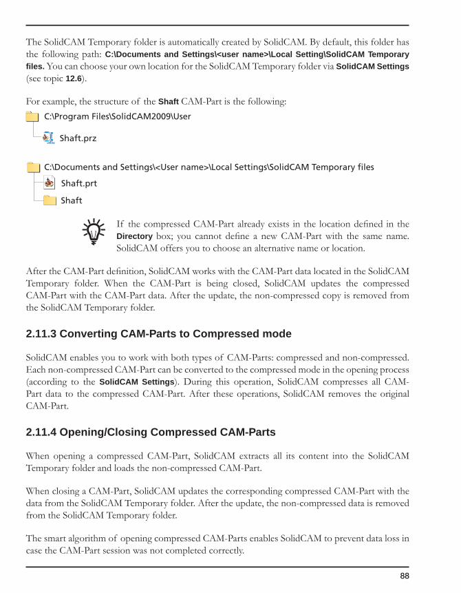
88
The SolidCAM Temporary folder is automatically created by SolidCAM. By default, this folder has the following path: C:\Documents and Settings\<user name>\Local Setting\SolidCAM Temporary files. You can choose your own location for the SolidCAM Temporary folder via SolidCAM Settings (see topic 12.6).
For example, the structure of the Shaft CAM-Part is the following:
If the compressed CAM-Part already exists in the location defined in the Directory box; you cannot define a new CAM-Part with the same name. SolidCAM offers you to choose an alternative name or location.
After the CAM-Part definition, SolidCAM works with the CAM-Part data located in the SolidCAM Temporary folder. When the CAM-Part is being closed, SolidCAM updates the compressed CAM-Part with the CAM-Part data. After the update, the non-compressed copy is removed from the SolidCAM Temporary folder.
2.11.3 Converting CAM-Parts to Compressed mode
SolidCAM enables you to work with both types of CAM-Parts: compressed and non-compressed. Each non-compressed CAM-Part can be converted to the compressed mode in the opening process (according to the SolidCAM Settings). During this operation, SolidCAM compresses all CAM-Part data to the compressed CAM-Part. After these operations, SolidCAM removes the original CAM-Part.
2.11.4 Opening/Closing Compressed CAM-Parts
When opening a compressed CAM-Part, SolidCAM extracts all its content into the SolidCAM Temporary folder and loads the non-compressed CAM-Part.
When closing a CAM-Part, SolidCAM updates the corresponding compressed CAM-Part with the data from the SolidCAM Temporary folder. After the update, the non-compressed data is removed from the SolidCAM Temporary folder.
The smart algorithm of opening compressed CAM-Parts enables SolidCAM to prevent data loss in case the CAM-Part session was not completed correctly.
Shaft.prz
Shaft.prt
Shaft
C:\Program Files\SolidCAM2009\User
C:\Documents and Settings\<User name>\Local Settings\SolidCAM Temporary files
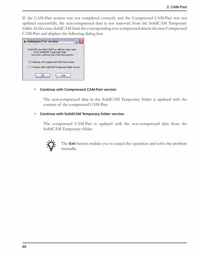
89
2. CAM-Part
If the CAM-Part session was not completed correctly and the Compressed CAM-Part was not updated successfully, the non-compressed data is not removed from the SolidCAM Temporary folder. In this case, SolidCAM finds the corresponding non-compressed data in the next Compressed CAM-Part and displays the following dialog box.
• Continue with Compressed CAM-Part version
The non-compressed data in the SolidCAM Temporary folder is updated with the content of the compressed CAM-Part.
• Continue with SolidCAM Temporary folder version
The compressed CAM-Part is updated with the non-compressed data from the SolidCAM Temporary folder.
The Exit button enables you to cancel the operation and solve the problem manually.
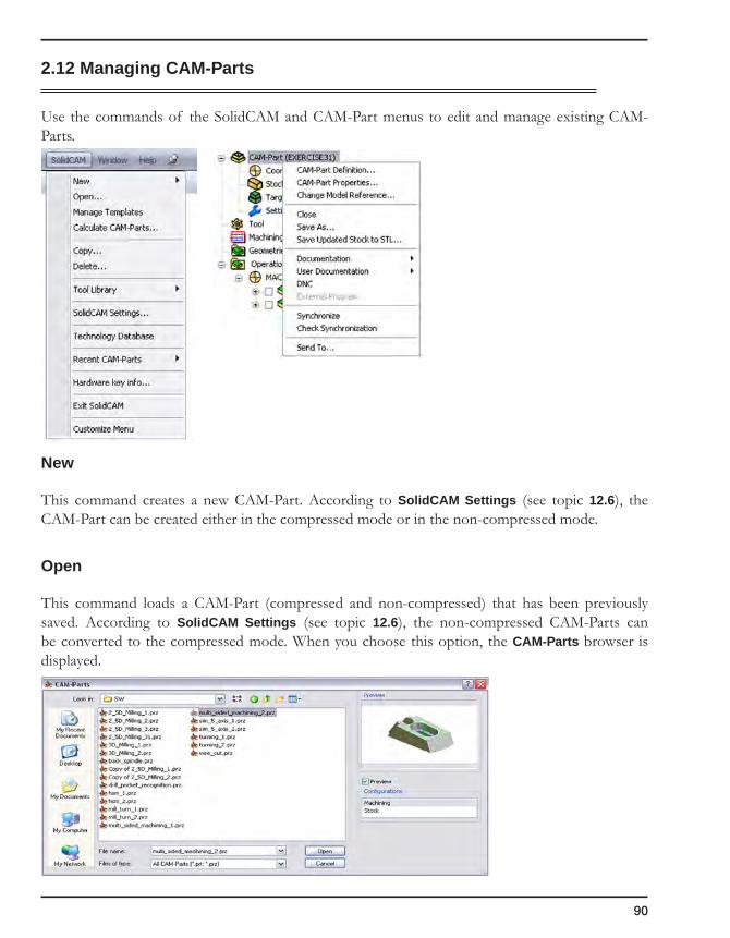
90
2.12 Managing CAM-Parts
Use the commands of the SolidCAM and CAM-Part menus to edit and manage existing CAM-Parts.
New
This command creates a new CAM-Part. According to SolidCAM Settings (see topic 12.6), the CAM-Part can be created either in the compressed mode or in the non-compressed mode.
Open
This command loads a CAM-Part (compressed and non-compressed) that has been previously saved. According to SolidCAM Settings (see topic 12.6), the non-compressed CAM-Parts can be converted to the compressed mode. When you choose this option, the CAM-Parts browser is displayed.

91
2. CAM-Part
1. Select the CAM-Part you want to load.
2. Double-click on the CAM-Part or select it and click on the Open button.
The default type for the Files of Type filter is defined in SolidCAM Settings.
If a CAM-Part was created with the previous SolidCAM version, the backup can be performed during the CAM-Part opening, if necessary. The backup is created as a copy of the original file in the Backup of <CAM-Part name> folder.
You can also open CAM-Parts by double-clicking on the *.prt files in the Windows Explorer environment.
Manage Templates
This command enables you to manage your operation and process templates using the Template Manager dialog box.
For more information on operation templates and process templates, see topic 5.2.2.
Close
SolidCAM closes the active CAM-Part. The Compressed CAM-Part file is being updated, if necessary.
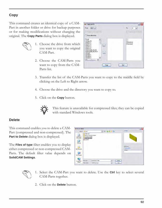
92
Copy
This command creates an identical copy of a CAM-Part in another folder or drive for backup purposes or for making modifications without changing the original. The Copy Parts dialog box is displayed.
1. Choose the drive from which you want to copy the original CAM-Part.
2. Choose the CAM-Parts you want to copy from the CAM-Parts list.
3. Transfer the list of the CAM-Parts you want to copy to the middle field by clicking on the Left to Right arrow.
4. Choose the drive and the directory you want to copy to.
5. Click on the Copy button.
This feature is unavailable for compressed files; they can be copied with standard Windows tools.
Delete
This command enables you to delete a CAM-Part (compressed and non-compressed). The Part to Delete dialog box is displayed.
The Files of type filter enables you to display either compressed or non-compressed CAM-Parts. The default filter value depends on SolidCAM Settings.
1. Select the CAM-Part you want to delete. Use the Ctrl key to select several CAM-Parts together.
2. Click on the Delete button.
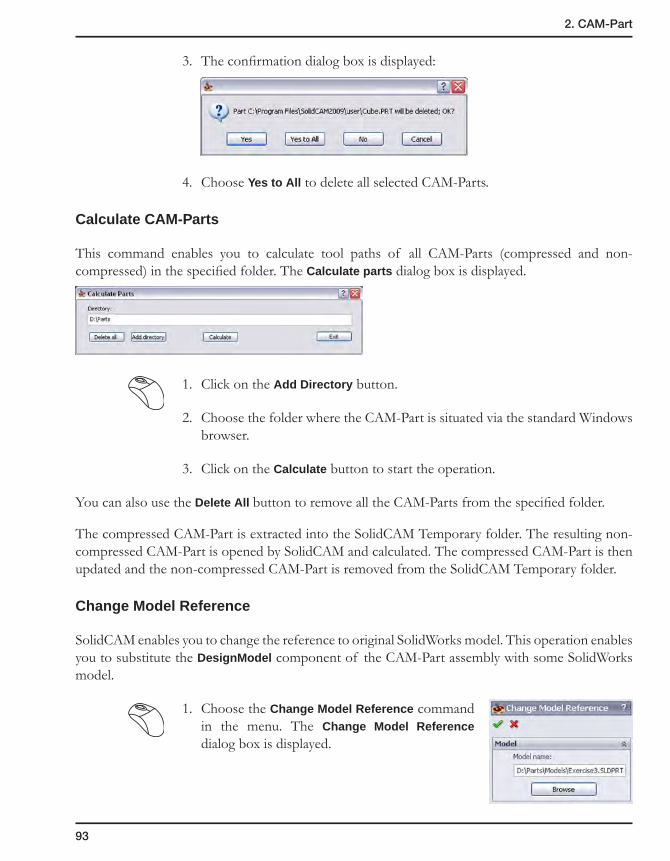
93
2. CAM-Part
3. The confirmation dialog box is displayed:
4. Choose Yes to All to delete all selected CAM-Parts.
Calculate CAM-Parts
This command enables you to calculate tool paths of all CAM-Parts (compressed and non-compressed) in the specified folder. The Calculate parts dialog box is displayed.
1. Click on the Add Directory button.
2. Choose the folder where the CAM-Part is situated via the standard Windows browser.
3. Click on the Calculate button to start the operation.
You can also use the Delete All button to remove all the CAM-Parts from the specified folder.
The compressed CAM-Part is extracted into the SolidCAM Temporary folder. The resulting non-compressed CAM-Part is opened by SolidCAM and calculated. The compressed CAM-Part is then updated and the non-compressed CAM-Part is removed from the SolidCAM Temporary folder.
Change Model Reference
SolidCAM enables you to change the reference to original SolidWorks model. This operation enables you to substitute the DesignModel component of the CAM-Part assembly with some SolidWorks model.
1. Choose the Change Model Reference command in the menu. The Change Model Reference dialog box is displayed.
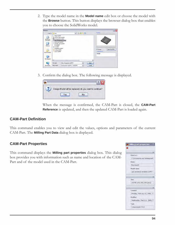
94
2. Type the model name in the Model name edit box or choose the model with the Browse button. This button displays the browser dialog box that enables you to choose the SolidWorks model.
3. Confirm the dialog box. The following message is displayed.
When the message is confirmed, the CAM-Part is closed, the CAM-Part Reference is updated, and then the updated CAM-Part is loaded again.
CAM-Part Definition
This command enables you to view and edit the values, options and parameters of the current CAM-Part. The Milling Part Data dialog box is displayed.
CAM-Part Properties
This command displays the Milling part properties dialog box. This dialog box provides you with information such as name and location of the CAM-Part and of the model used in the CAM-Part.

95
2. CAM-Part
Save As
This command enables you to save the active CAM-Part to the disk with a new name or in a new location.
When this option is chosen, the Save As dialog box is displayed.
Save as Type
This option enables you to choose the type of the CAM-Part: compressed or non-compressed. The default value of the Save as Type filter is the same as the type of the original CAM-Part.
The conversion of the compressed CAM-Part to non-compressed is unavailable.
Save as copy
• When this option is not available, the saved CAM-Part is loaded instead of the current CAM-Part.
• When this option is available, SolidCAM stays with the current CAM-Part.
Recent CAM-Parts
This option displays a list of the last nine CAM-Parts you worked with in SolidCAM. You can open the file by clicking on its name.

96
Saving the updated stock in the STL format
SolidCAM parts can be machined in a sequence of stages on different CNC-machines, while the updated stock model is shared between these stages.
This functionality enables you to define a new CAM-Part based on some other pre-machined CAM-Part, using the result of machining of the pre-machined part for the stock definition. Machining of a part can thus be performed in several stages, with one CAM-Part for each stage, by passing the machining results from one stage to the next through an updated stock model obtained after the last operation of each CAM-Part and saved in the STL format.
1. Right-click on the CAM-Part header in SolidCAM Manager and choose the Save updated stock to STL command from the menu.
2. The Save updated stock to STL dialog box is displayed.
Define the name and location for your file. The default name of the updated stock model STL file is inherited from the CAM-Part name. The default location of the STL file is the SolidCAM Part folder for regular SolidCAM Parts (*.prt). For compressed CAM-Parts (*.prz), the default location is that of the compressed CAM-Part files.
3. Click on the Save button.
SolidCAM generates the STL file according to the HostCAD coordinate system.
When the STL file is successfully generated, the notification message is displayed.
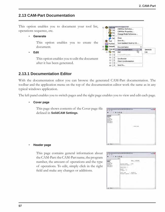
97
2. CAM-Part
2.13 CAM-Part Documentation
This option enables you to document your tool list, operations sequence, etc.
• Generate
This option enables you to create the document.
• Edit
This option enables you to edit the document after it has been generated.
2.13.1 Documentation Editor
With the documentation editor you can browse the generated CAM-Part documentation. The toolbar and the application menu on the top of the documentation editor work the same as in any typical windows application.
The left panel enables you to switch pages and the right page enables you to view and edit each page.
• Coverpage
This page shows contents of the Cover page file defined in SolidCAM Settings.
• Headerpage
This page contains general information about the CAM-Part: the CAM-Part name, the program number, the amount of operations and the type of operations. To edit, simply click in the right field and make any changes or additions.

98
• ToolTablepage
This page contains all the relevant information about the tools used in the CAM-Part: the tool number, the tool diameter, the corner radius, the tool type, the number of teeth and any other information that is relevant to each tool. To edit, simply click in the right field and make any changes or additions.
• Operationstablepage
This page contains the list of all operations in the CAM-Part.
• Operationpages
Under this page, there is a page for each operation name. This page gives you a detailed list of all of the fields you have chosen in the operation and their values.
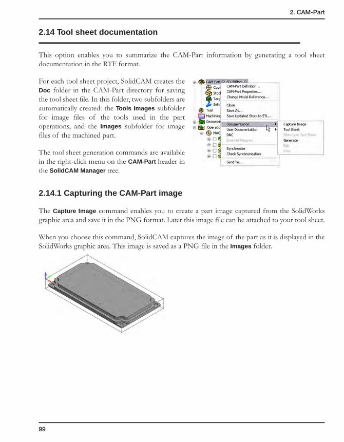
99
2. CAM-Part
2.14 Tool sheet documentation
This option enables you to summarize the CAM-Part information by generating a tool sheet documentation in the RTF format.
For each tool sheet project, SolidCAM creates the Doc folder in the CAM-Part directory for saving the tool sheet file. In this folder, two subfolders are automatically created: the Tools Images subfolder for image files of the tools used in the part operations, and the Images subfolder for image files of the machined part.
The tool sheet generation commands are available in the right-click menu on the CAM-Part header in the SolidCAM Manager tree.
2.14.1 Capturing the CAM-Part image
The Capture Image command enables you to create a part image captured from the SolidWorks graphic area and save it in the PNG format. Later this image file can be attached to your tool sheet.
When you choose this command, SolidCAM captures the image of the part as it is displayed in the SolidWorks graphic area. This image is saved as a PNG file in the Images folder.
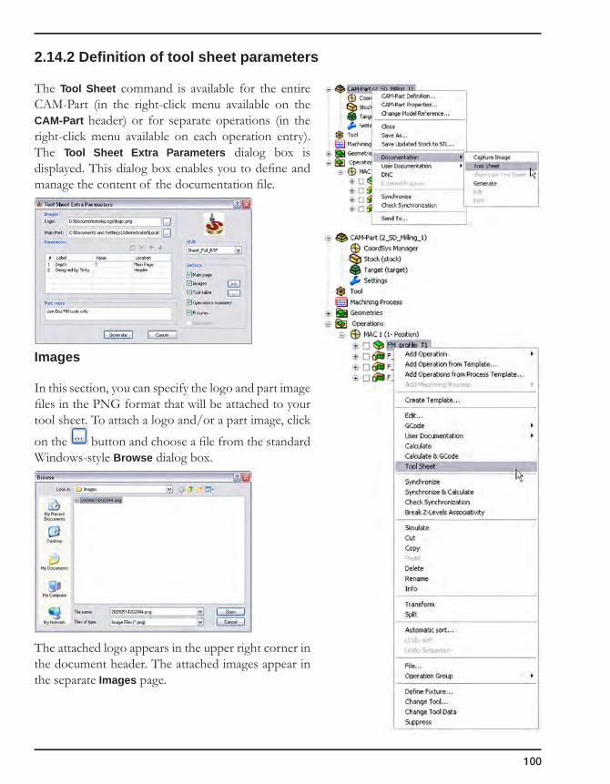
100
2.14.2 Definition of tool sheet parameters
The Tool Sheet command is available for the entire CAM-Part (in the right-click menu available on the CAM-Part header) or for separate operations (in the right-click menu available on each operation entry). The Tool Sheet Extra Parameters dialog box is displayed. This dialog box enables you to define and manage the content of the documentation file.
Images
In this section, you can specify the logo and part image files in the PNG format that will be attached to your tool sheet. To attach a logo and/or a part image, click
on the button and choose a file from the standard Windows-style Browse dialog box.
The attached logo appears in the upper right corner in the document header. The attached images appear in the separate Images page.
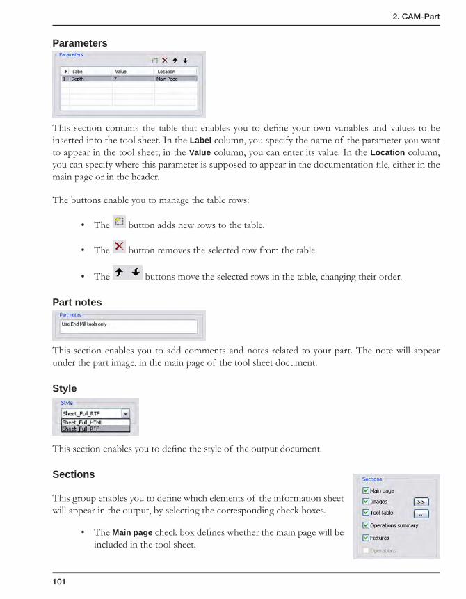
101
2. CAM-Part
Parameters
This section contains the table that enables you to define your own variables and values to be inserted into the tool sheet. In the Label column, you specify the name of the parameter you want to appear in the tool sheet; in the Value column, you can enter its value. In the Location column, you can specify where this parameter is supposed to appear in the documentation file, either in the main page or in the header.
The buttons enable you to manage the table rows:
• The button adds new rows to the table.
• The button removes the selected row from the table.
• The buttons move the selected rows in the table, changing their order.
Part notes
This section enables you to add comments and notes related to your part. The note will appear under the part image, in the main page of the tool sheet document.
Style
This section enables you to define the style of the output document.
Sections
This group enables you to define which elements of the information sheet will appear in the output, by selecting the corresponding check boxes.
• The Main page check box defines whether the main page will be included in the tool sheet.

102
• The Images check box defines whether the Images page will be included in the tool sheet. The button displays the location of the part captured images in the Windows Explorer.
• The Tool table check box defines whether the Tool table pages will be included in the tool
sheet. The button displays the dialog box that enables you to specify the required tool data to appear in the Tool table summary by selecting check boxes.
• The Operations summary check box defines whether the Operation summary page will be included in the tool sheet.
• The Fixtures check box defines whether the Fixture page will be included in the tool sheet.
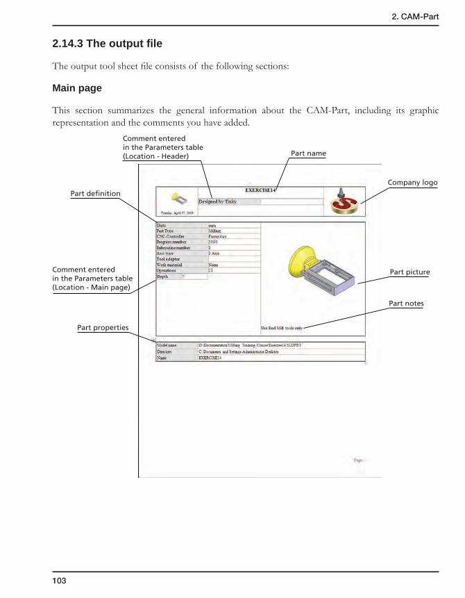
103
2. CAM-Part
2.14.3 The output file
The output tool sheet file consists of the following sections:
Main page
This section summarizes the general information about the CAM-Part, including its graphic representation and the comments you have added.
Part picture
Part notes
Company logo
Part definition
Part properties
Comment enteredin the Parameters table(Location - Header)
Comment enteredin the Parameters table(Location - Main page)
Part name
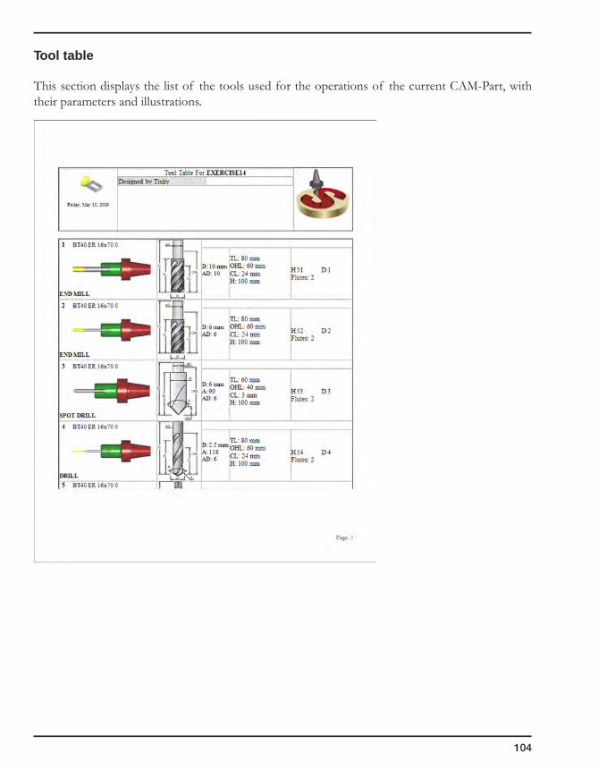
104
Tool table
This section displays the list of the tools used for the operations of the current CAM-Part, with their parameters and illustrations.

105
2. CAM-Part
Operations summary
This section summarizes the operations defined for the current CAM-Part.

106
Fixtures
This section shows how the part must be fixed on the CNC-machine table.

107
2. CAM-Part
2.14.4 Show Last Tool Sheet
This command enables you to display the last generated tool sheet for the current part, instead of generating it anew. The Tool Sheet Extra Parameters dialog box is displayed so that you can view the defined parameters of the last tool sheet generation.
In this dialog box, you can edit only the Style and the Sections parameters to alter the document appearance and define which sections of the last tool sheet you want to display.
The Show button displays the generated tool sheet.

108
2.15 Milling STL CAM-Part
This functionality enables you to define the machining projects based on output of 3D scanning devices in the STL format. The received STL file contains data on the shape and visual properties of the scanned real-world object upon which the machining project will be based. Such parts can be machined using the SolidCAM 3D, HSM and 5-Axis milling capabilities. The peculiarity of such projects definition is that the STL graphic body cannot be divided into separate elements in the way a CAD design model can be. Therefore, the definition of such CAM-Part is different from a regular milling project.
2.15.1 Starting a new Milling-STL CAM-Part
1. Click SolidCAM, New, Milling-STL.
2. The New Milling Part dialog box is displayed and enables you to choose an STL file similar to the CAD design file chosen for CAM-Part definition.
3. In the Directory section, you need to specify the path to the location where the CAM-Part will be saved by entering manually or by clicking on the Browse button.

109
2. CAM-Part
4. In the Model name section, click on the Browse button and choose the required STL file.
5. In the Name section, you need to enter the name for your machining project.
When you confirm the New Milling Part dialog box, the Milling Part Data dialog box is displayed as for a regular milling project definition. The graphic body is displayed in the SolidWorks graphic area. It can be zoomed and rotated.
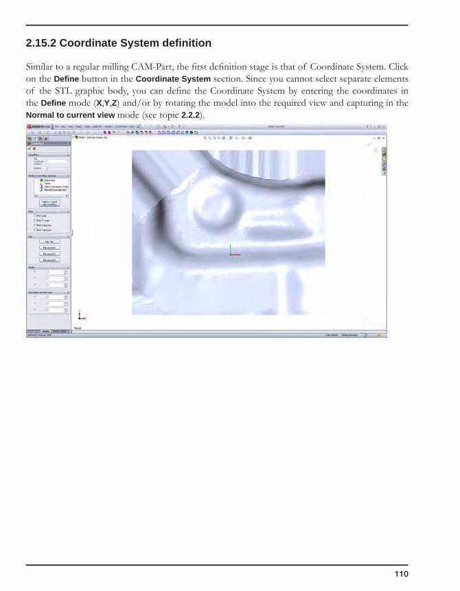
110
2.15.2 Coordinate System definition
Similar to a regular milling CAM-Part, the first definition stage is that of Coordinate System. Click on the Define button in the Coordinate System section. Since you cannot select separate elements of the STL graphic body, you can define the Coordinate System by entering the coordinates in the Define mode (X,Y,Z) and/or by rotating the model into the required view and capturing in the Normal to current view mode (see topic 2.2.2).

111
2. CAM-Part
2.15.3 Stock model definition
When the Coordinate System is defined, a box is calculated surrounding the model. Using this box, you can define the Stock model with the 3D Box option (see topic 2.4.1).
2.15.4 Target model definition
The target model is defined by clicking on the Browse button in the Choose STL dialog box and choosing the original STL file from the browser dialog box.
When the CAM-Part is defined, you can add 3D Milling, HSM, HSS and 5-Axis operations for its machining.
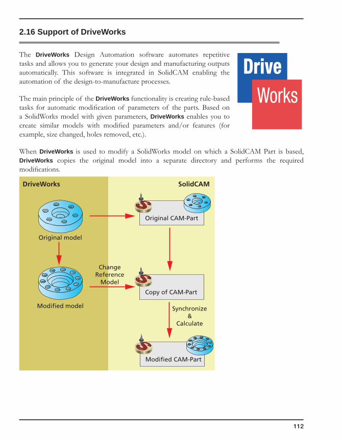
112
2.16 Support of DriveWorks
The DriveWorks Design Automation software automates repetitive tasks and allows you to generate your design and manufacturing outputs automatically. This software is integrated in SolidCAM enabling the automation of the design-to-manufacture processes.
The main principle of the DriveWorks functionality is creating rule-based tasks for automatic modification of parameters of the parts. Based on a SolidWorks model with given parameters, DriveWorks enables you to create similar models with modified parameters and/or features (for example, size changed, holes removed, etc.).
When DriveWorks is used to modify a SolidWorks model on which a SolidCAM Part is based, DriveWorks copies the original model into a separate directory and performs the required modifications.
Original model
ChangeReference
Model
Synchronize&
Calculate
SolidCAMDriveWorks
Modified model
Original CAM-Part
Copy of CAM-Part
Modified CAM-Part
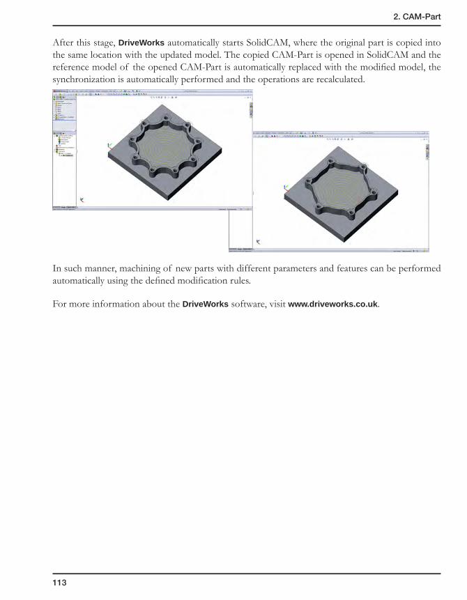
113
2. CAM-Part
After this stage, DriveWorks automatically starts SolidCAM, where the original part is copied into the same location with the updated model. The copied CAM-Part is opened in SolidCAM and the reference model of the opened CAM-Part is automatically replaced with the modified model, the synchronization is automatically performed and the operations are recalculated.
In such manner, machining of new parts with different parameters and features can be performed automatically using the defined modification rules.
For more information about the DriveWorks software, visit www.driveworks.co.uk.

114
3Tools andTool Libraries
The tool commands can be used to create and manage tools and tool libraries in SolidCAM. You can save your programming time if you save the tools you use most often in customizable tool libraries.
The tool libraries can be based on machine tooling, materials or any other personal criteria. When you define your machining operations, you can then load the tool, and all its parameters, feed and spin values are automatically copied into the operation.
Working with Part Tool Table
Working with Current Tool Library
Managing Tool Libraries
Defining tools
Tool types
Shaped tools
Tool holding system

116
3.1 User-Defined Tool Types
For easier identification and classification of tools, you can define your own tool types. SolidCAM offers you the following default tool types:
• End mill
• Ball nose mill
• Bull nose mill
• Face mill
• Dove tail mill
• Taper mill
• Slot mill
• Lollipop mill
• Engraving tool
• Center drill
• Spot drill
• Drill
• Chamfer drill
• Tap
• Reamer
• Bore
• Thread mill
• Thread taper
User-defined tool types can also be used to define new tools and to search tool libraries.

3. Tools and Tool Libraries
117
3.1.1 End mill
This tool type is used for the definition of rough/finish end mills.
The tools of this type are defined with the parameters shown in the image.
The diameter and the length of the cylindrical arbor are defined as Arbor Diameter and (Total Length – Shoulder Length), respectively. The Shoulder Length value must be greater than or equal to that of the Cutting Length, and equal to or smaller than that of the Outside Holder Length.
When a new tool is created, the default value of the Arbor Diameter is equal to that of the Diameter, and the default value of the Shoulder Length is equal to that of the Cutting Length.
OutsideHolderLength
CuttingLength
Arbor Diameter
Diameter
TotalLength
ShoulderLength

118
3.1.2 Ball nose mill
A tool of this type is defined with the parameters shown in the image.
The Corner Radius value of a Ball nose mill tool is equal to half the Diameter value and cannot be changed.
The diameter and the length of the cylindrical arbor are defined as Arbor Diameter and (Total Length – Shoulder Length), respectively. The Shoulder Length value must be greater than or equal to that of the Cutting Length, and equal to or smaller than that of the Outside Holder Length.
When a new tool is created, the default value of the Arbor Diameter is equal to that of the Diameter, and the default value of the Shoulder Length is equal to that of the Cutting Length.
OutsideHolderLengthCutting
Length
Corner Radius
Arbor Diameter
Diameter
TotalLength
ShoulderLength

3. Tools and Tool Libraries
119
3.1.3 Bull nose mill
A tool of this type is defined with the parameters shown in the image.
The Corner Radius value of a Bull nose mill tool must be in the range from 0 to half the Diameter value.
The diameter and the length of the cylindrical arbor are defined as Arbor Diameter and (Total Length – Shoulder Length), respectively. The Shoulder Length value must be greater than or equal to that of the Cutting Length, and equal to or smaller than that of the Outside Holder Length.
When a new tool is created, the default value of the Arbor Diameter is equal to that of the Diameter, and the default value of the Shoulder Length is equal to that of the Cutting Length.
OutsideHolderLengthCutting
Length
Corner Radius
Arbor Diameter
Diameter
TotalLength
ShoulderLength
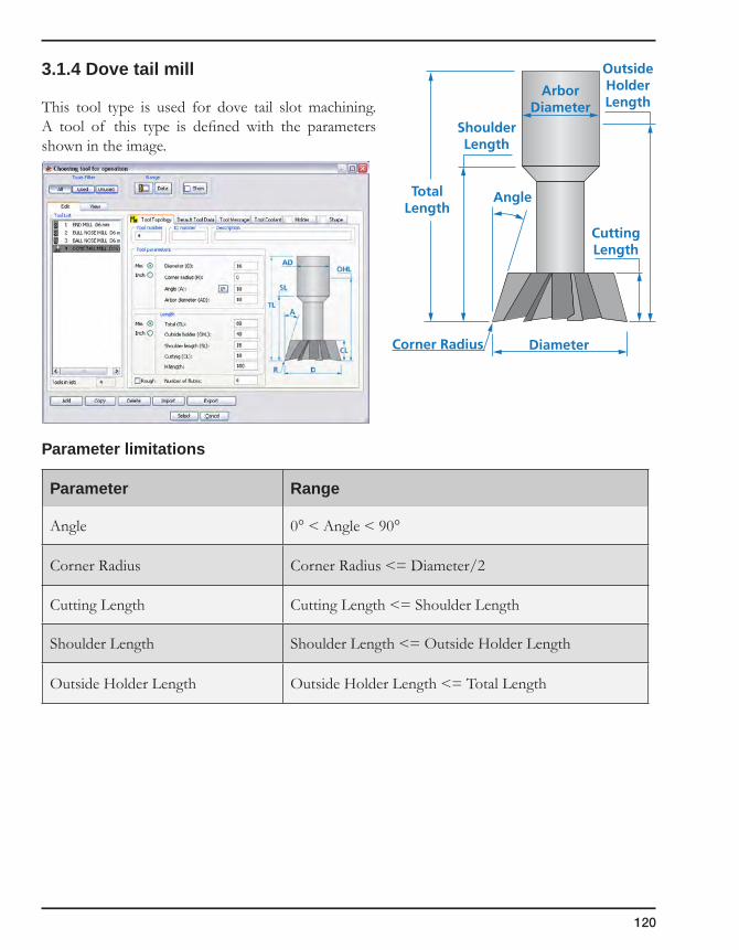
120
3.1.4 Dove tail mill
This tool type is used for dove tail slot machining. A tool of this type is defined with the parameters shown in the image.
Parameter limitations
Parameter Range
Angle 0° < Angle < 90°
Corner Radius Corner Radius <= Diameter/2
Cutting Length Cutting Length <= Shoulder Length
Shoulder Length Shoulder Length <= Outside Holder Length
Outside Holder Length Outside Holder Length <= Total Length
OutsideHolderLength
CuttingLength
DiameterCorner Radius
AngleTotalLength
ShoulderLength
ArborDiameter
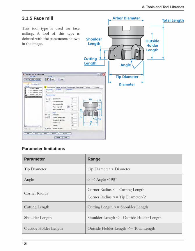
3. Tools and Tool Libraries
121
3.1.5 Face mill
This tool type is used for face milling. A tool of this type is defined with the parameters shown in the image.
Parameter limitations
Parameter Range
Tip Diameter Tip Diameter < Diameter
Angle 0° < Angle < 90°
Corner RadiusCorner Radius <= Cutting Length
Corner Radius <= Tip Diameter/2
Cutting Length Cutting Length <= Shoulder Length
Shoulder Length Shoulder Length <= Outside Holder Length
Outside Holder Length Outside Holder Length <= Total Length
OutsideHolderLength
CuttingLength
Arbor Diameter
Diameter
Tip Diameter
Total Length
ShoulderLength
Angle

122
3.1.6 Slot mill
This tool is used in a variety of applications from simple 2.5D undercut profiles all the way up to machining cavities in Simultaneous 5 Axis operations. The parametric definition of a slot mill tool also enables you to define a cylindrical tool with a tool shank with a relieved diameter.
A tool of this type is defined with the parameters shown in the image.
OutsideHolderLength
CuttingLengthDiameter
CornerRadius
TotalLength
ArborDiameter

3. Tools and Tool Libraries
123
3.1.7 Taper mill
This tool type is supported in the calculations of the Sim. 5 Axis and 3D Milling Rough and Finish operations. In 2.5D Milling operations such as Profile and Pocket, only the bottom diameter is taken into account in the tool path calculation. This tool is used for milling internal or external walls with a constant draft angle.
A tool of this type is defined with the parameters shown in the image.
The diameter and the length of the cylindrical tool arbor are defined as Arbor Diameter and (Total Length – Shoulder Length), respectively. The Shoulder Length value must be greater than or equal to that of the Cutting Length, and equal to or smaller than that of the Outside Holder Length.
• The default Arbor Diameter value is equal to that of the Diameter;
• The Shoulder Length value is equal to that of the following expression:
Cutting Length + (Outside Holder Length – Cutting Length)/2.
To define the taper tool by Tip diameter or by Cone Length, select the appropriate check box near the Tip Diameter or the Cone Length edit boxes.
When the Tip Diameter check box is selected, the Cone Length check box is unselected and the relevant edit box is disabled; the Cone Length value is thus automatically calculated.
OutsideHolderLength
CuttingLength
Angle
Diameter
TipDiameter
CornerRadius
ArborDiameter
TotalLength Shoulder
Length
ConeLength

124
When the Cone Length check box is selected, the Tip Diameter check box is unselected and the relevant edit box is disabled; the Tip Diameter value is thus automatically calculated.
Note that the Tip Diameter is the diameter of the virtual intersection of the conical shape with the bottom plane.
Parameter limitations
Parameter Range
Tip Diameter Tip Diameter < Diameter
Angle 0° < Angle < 180°
Corner RadiusCorner Radius <= Tip Diameter/2
Corner Radius < Cone length
Cutting Length Cutting Length <= Shoulder Length
Shoulder Length Shoulder Length <= Outside Holder Length
Outside Holder Length Outside Holder Length <= Total Length
Tip Diameter

3. Tools and Tool Libraries
125
3.1.8 Engraving tool
This tool type is used for engraving. A tool of this type is defined with the parameters shown in the image.
Parameter limitations
Parameter Range
Angle 0° < Angle < 90°
Corner Radius Corner Radius <= Diameter/2
Cutting Length Cutting Length <= Shoulder Length
Shoulder Length Shoulder Length <= Outside Holder Length
Outside Holder Length Outside Holder Length <= Total Length
OutsideHolderLength
CuttingLength
Tip Diameter
Diameter
Corner Radius
Angle
TotalLength
ShoulderLength
Arbor Diameter
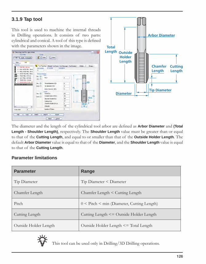
126
3.1.9 Tap tool
This tool is used to machine the internal threads in Drilling operations. It consists of two parts: cylindrical and conical. A tool of this type is defined with the parameters shown in the image.
The diameter and the length of the cylindrical tool arbor are defined as Arbor Diameter and (Total Length - Shoulder Length), respectively. The Shoulder Length value must be greater than or equal to that of the Cutting Length, and equal to or smaller than that of the Outside Holder Length. The default Arbor Diameter value is equal to that of the Diameter, and the Shoulder Length value is equal to that of the Cutting Length.
Parameter limitations
Parameter Range
Tip Diameter Tip Diameter < Diameter
Chamfer Length Chamfer Length < Cutting Length
Pitch 0 < Pitch < min (Diameter, Cutting Length)
Cutting Length Cutting Length <= Outside Holder Length
Outside Holder Length Outside Holder Length <= Total Length
This tool can be used only in Drilling/3D Drilling operations.
OutsideHolderLength
CuttingLength
Tip Diameter
ChamferLength
Diameter
TotalLength
Arbor Diameter
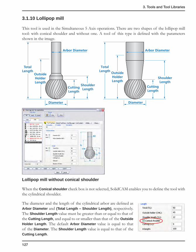
3. Tools and Tool Libraries
127
3.1.10 Lollipop mill
This tool is used in the Simultaneous 5 Axis operations. There are two shapes of the lollipop mill tool: with conical shoulder and without one. A tool of this type is defined with the parameters shown in the image.
Lollipop mill without conical shoulder
When the Conical shoulder check box is not selected, SolidCAM enables you to define the tool with the cylindrical shoulder.
The diameter and the length of the cylindrical arbor are defined as Arbor Diameter and (Total Length – Shoulder Length), respectively. The Shoulder Length value must be greater than or equal to that of the Cutting Length, and equal to or smaller than that of the Outside Holder Length. The default Arbor Diameter value is equal to that of the Diameter. The Shoulder Length value is equal to that of the Cutting Length.
OutsideHolderLength
CuttingLength
Arbor Diameter
Diameter
TotalLength
ShoulderLength
OutsideHolderLength
CuttingLength
Arbor Diameter
Diameter
TotalLength
ShoulderLength
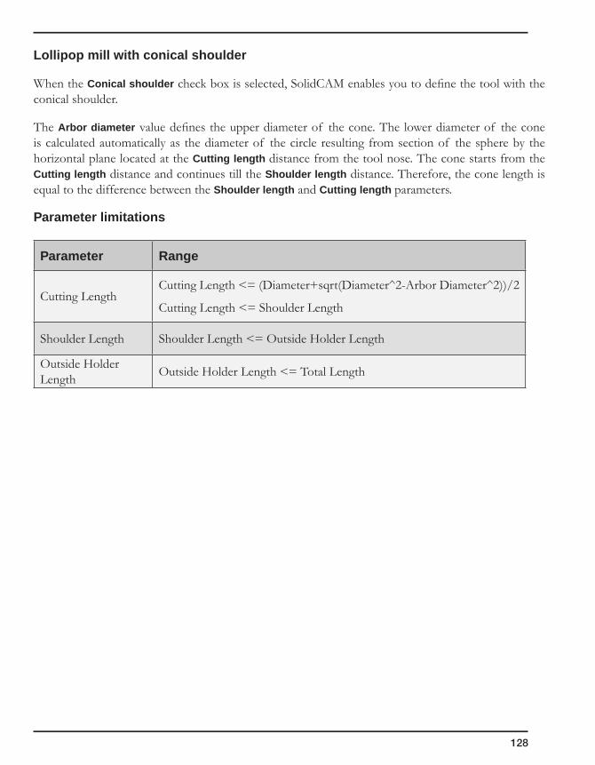
128
Lollipop mill with conical shoulder
When the Conical shoulder check box is selected, SolidCAM enables you to define the tool with the conical shoulder.
The Arbor diameter value defines the upper diameter of the cone. The lower diameter of the cone is calculated automatically as the diameter of the circle resulting from section of the sphere by the horizontal plane located at the Cutting length distance from the tool nose. The cone starts from the Cutting length distance and continues till the Shoulder length distance. Therefore, the cone length is equal to the difference between the Shoulder length and Cutting length parameters.
Parameter limitations
Parameter Range
Cutting LengthCutting Length <= (Diameter+sqrt(Diameter^2-Arbor Diameter^2))/2
Cutting Length <= Shoulder Length
Shoulder Length Shoulder Length <= Outside Holder Length
Outside Holder Length Outside Holder Length <= Total Length

3. Tools and Tool Libraries
129
3.1.11 Thread mill
This tool is intended to machine the internal and external threads in Thread Milling operations.
The following parameters define the geometry of thread mill tools.
Pitch
SolidCAM enables you to define the Pitch of the thread as a Metric value (MM) or as a number of tracks per inch (TPI).
When defining the tool parameters in the Part Tool Table, you can define the Pitch in accordance with international standards such as ISO, Whitworth, and so forth.
In the Pitch/Standard field, choose the Table option and click on the arrow to open the list and choose the standard according to which you want to define the thread pitch.
This list is available only if the Threading table is defined in the SolidCAM Settings dialog box (see topic 12.2.3).
When you choose one of the standards from the list, the corresponding table is displayed in a separate window.
OutsideHolderLength
TotalLength
ThreadCuttingLength
ShoulderLength
ArborDiameter
Thread Diameter

130
Choose the required value and confirm with the OK button.
You can open this table as an Excel file and edit its content. The path to the table file can be found on the User directories page of the SolidCAM Settings dialog box (see topic 12.2.3).
SolidCAM provides you with a link to the Vardex software for thread milling tool selection from the Vardex tools library – TM Gen (www.vardex.com). This link enables you to define the thread mill tool parameters and, based on this, it will search the Vardex library for the thread milling tools that fit these parameters; you can then choose one of the offered tools for the operation.
When the Vardex option is chosen in the Standard combo box, SolidCAM launches the Vardex tool library wizard (TM Wizard). The wizard guides you through the steps to define the parameters of the tool you are looking for, selects a number of tools from the library that fit these parameters and then enables you to choose one of these tools. When the tool is chosen, it is imported into the SolidCAM tool library.
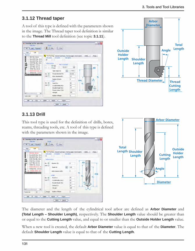
3. Tools and Tool Libraries
131
3.1.12 Thread taper
A tool of this type is defined with the parameters shown in the image. The Thread taper tool definition is similar to the Thread Mill tool definition (see topic 3.1.11).
3.1.13 Drill
This tool type is used for the definition of drills, bores, reams, threading tools, etc. A tool of this type is defined with the parameters shown in the image.
The diameter and the length of the cylindrical tool arbor are defined as Arbor Diameter and (Total Length – Shoulder Length), respectively. The Shoulder Length value should be greater than or equal to the Cutting Length value, and equal to or smaller than the Outside Holder Length value.
When a new tool is created, the default Arbor Diameter value is equal to that of the Diameter. The default Shoulder Length value is equal to that of the Cutting Length.
OutsideHolderLength
TotalLength
ThreadCuttingLength
ShoulderLength
ArborDiameter
Thread Diameter
Angle
OutsideHolderLength
CuttingLength
Diameter
Angle
TotalLength Shoulder
Length
Arbor Diameter

132
3.1.14 Center drill
This tool type is used for center drilling in Drilling operations. A tool of this type is defined with the parameters shown in the image.
When this tool is used in combination with the Use chamfer option, SolidCAM calculates the drilling depth according to the following expression:
Drilling Depth = Tip Length + Arbor Diameter/2 + cotan(Shoulder Angle/2)
OutsideHolderLength
Tip Diameter TipLength
TotalLength
ShoulderAngle
CuttingLength
Angle
ArborDiameter
Tip Diameter
Chamfer Diameter
Shoulder Angle
Arbor Diameter
Cutting Length
Tip Length
Chamfer Diameter
Drilling Depth

3. Tools and Tool Libraries
133
Parameter limitations
Parameter Range
Tip Diameter Tip Diameter < Arbor Diameter
Tip Angle 0° < Tip Angle < 180°
Shoulder Angle 0° < Shoulder Angle < 180°
Tip Length Tip Length <= Cutting Length
Cutting Length Cutting Length <= Outside Holder Length
Outside Holder Length Outside Holder Length <= Total Length
The length of the conical part defined by Tip Diameter and Tip Angle must be equal to or smaller than the Tip Length value. The length of conical part can be calculated according to the following expression: Cone Length = Tip diameter/(2*tan( Tip angle/2)).

134
3.1.15 Spot drill
This tool type is used for center drilling and chamfering. A tool of this type is defined with the parameters shown in the image.
Parameter limitations
Parameter Range
Angle 0° < Angle < 180°
Tip Length Tip Length <= Cutting Length
Cutting Length Cutting Length <= Outside Holder Length
Outside Holder Length Outside Holder Length <= Total Length
Note that the Cutting Length edit box is unavailable. This value is calculated automatically according to the Diameter and Angle values.
OutsideHolderLength
Cutting Length
Diameter
Angle
TotalLength
ShoulderLength
Arbor Diameter
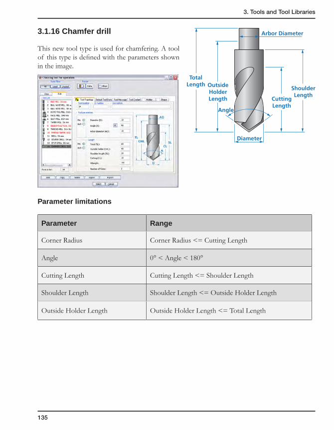
3. Tools and Tool Libraries
135
3.1.16 Chamfer drill
This new tool type is used for chamfering. A tool of this type is defined with the parameters shown in the image.
Parameter limitations
Parameter Range
Corner Radius Corner Radius <= Cutting Length
Angle 0° < Angle < 180°
Cutting Length Cutting Length <= Shoulder Length
Shoulder Length Shoulder Length <= Outside Holder Length
Outside Holder Length Outside Holder Length <= Total Length
OutsideHolderLength Cutting
Length
Arbor Diameter
Diameter
TotalLength
ShoulderLength
Angle

136
3.1.17 Reamer
This tool is used to machine precise holes in Drilling operations. A tool of this type is defined with the parameters shown in the image.
The diameter and the length of the cylindrical tool arbor are defined as Arbor Diameter and (Total Length – Shoulder Length), respectively. The Shoulder Length value must be greater than or equal to that of the Cutting Length, and equal to or smaller than that of the Outside Holder Length. The default Arbor Diameter value is equal to that of the Diameter.
Parameter limitations
Parameter Range
Cutting Length Chamfer Length <= Cutting Length <= Outside Holder Length
Shoulder Length Shoulder Length <= Outside Holder Length
Outside Holder Length Outside Holder Length <= Total Length
OutsideHolderLength
CuttingLength
ChamferLengthDiameter
TotalLength
ArborDiameter

3. Tools and Tool Libraries
137
3.1.18 Bore
This tool type is used for boring in Drilling operations. A tool of this type is defined with the parameters shown in the image.
Parameter limitations
Parameter Range
Corner Radius Corner Radius <= Cutting Length
Angle 0° < Angle < 90°
Cutting Length Cutting Length <= Shoulder Length
Shoulder Length Shoulder Length <= Outside Holder Length
Outside Holder Length Outside Holder Length <= Total Length
OutsideHolderLength
TotalLength
ShoulderLength
ArborDiameter
Diameter
CuttingLength
Corner Radius
Angle

138
3.1.19 Shaped Tools
This tool type is used for the definition of shaped end/rough mills and drill tools. The tool shape is defined by a sketch. The Tool Diameter defined in the Part Tool Table describes the cutting diameter of the shaped tool that will be coincident to the machining geometry.
For more information on Shaped tools, see topic 3.10.
3.1.20 Add new tool types
Based on one of the default tool types, you can create your own ones.
1. Click SolidCAM in the SolidWorks main menu and choose Tool Library, Tool type names.
The Tool Type Names dialog box is displayed. This dialog box shows the user-defined tool type names and their actual SolidCAM default internal tool types.
2. In the Tool Type Names dialog box, right-click on an existing tool type name, e.g. End Mill.
3. Choose Add from the menu.
4. A new entry is created. Enter the name of the user-defined tool type.
5. By default, the new entry is of the Drill tool type. Right-click on the Drill field and select the relevant tool type from the list.

3. Tools and Tool Libraries
139
6. When you finished making changes in the Tool type list, click on the Save button to confirm your changes.
Double-click the tool type name to rename existing entries.
3.1.21 Tool type options
You can manage the user-defined tool types in the list.
1. In the Tool Type Names dialog box, right-click an existing tool type name.
2. Choose the Add or Rename option from the menu.

140
3.2 Tool Libraries
The tool libraries can be based on machine tooling, materials or any other personal criteria. When you define your machining operations, you can then load the tool, and all its parameters, feed and spin values are automatically copied to the operation.
The Part Tool Table is the tool library that contains all tools available for use in a specific CAM-Part. The Part Tool Table is stored within the CAM-Part.
When you start a new CAM-Part and you want to copy the contents of a specific tool library into the Part Tool Table of this CAM-Part automatically, specify its name in the MAC file of the CNC-machine. This file is called the Machine Tool Table.
The Machine Tool table is defined in the MAC file by the following parameter: tool_table_name = name; where name (without an extension) is the name of the Tool Library located in the SolidCAM Tool Libraries folder defined in the SolidCAM Settings (see topic 12.2.2).
Generally, the Machine Tool Table contains the tools situated in the Tool Magazine of the specified CNC-machine.
SolidCAM enables you to define any number of Tool Libraries. Each tool from the Tool Libraries can be imported into the Part Tool Table. You can define one Tool Library that has a top priority in the list for import: the Current Tool Library.
Operation Operation Operation
Tool Tool ToolCAM-Part
Tools imported at user choise
Machine Tool Table
Tool Library
Current Tool Library
Tool Library Tool Library
Tool Library
Tool Library
Part Tool Table
Tools imported at start
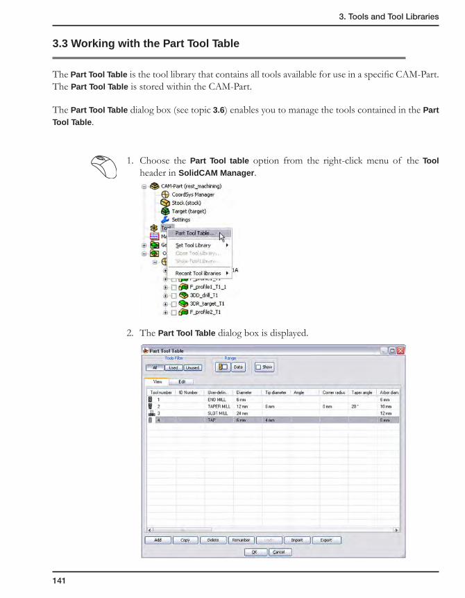
3. Tools and Tool Libraries
141
3.3 Working with the Part Tool Table
The Part Tool Table is the tool library that contains all tools available for use in a specific CAM-Part. The Part Tool Table is stored within the CAM-Part.
The Part Tool Table dialog box (see topic 3.6) enables you to manage the tools contained in the Part Tool Table.
1. Choose the Part Tool table option from the right-click menu of the Tool header in SolidCAM Manager.
2. The Part Tool Table dialog box is displayed.

142
3.4 Working with the Current Tool Library
SolidCAM enables you to manage your Current Tool Libraries using the right-click menu of the Tool header in SolidCAM Manager.
• SetToolLibrary
This option enables you to set the Current Tool Library. You have to specify the type of the Current Tool Library (Milling, Turning or Turn-Mill) and choose the relevant Tool Library from the browser dialog box. The Current Tool Library is selected and displayed in the Tool Table dialog box (see topic 3.6).
• CloseToolLibrary
This option enables you to close the Current Tool Library.
This option is available only when the Current Tool Library is already defined.
• ShowToolLibrary
This option enables you to display the content of the Current Tool Library. The Tool Table dialog box enables you to manage the tools in the Current Tool Library.
This option is available only when the Current Tool Library is already defined.
• RecentToolLibraries
This option displays the list of recently loaded Current Tool Libraries. You can open a file by simply clicking on its name in the list. The Tool Table dialog box is displayed.
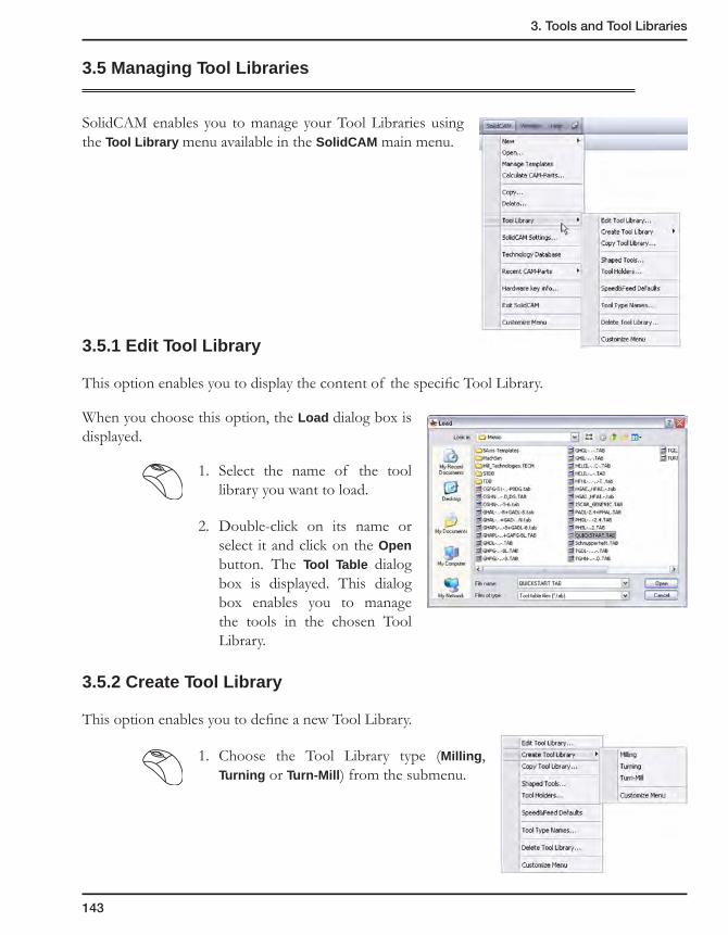
3. Tools and Tool Libraries
143
3.5 Managing Tool Libraries
SolidCAM enables you to manage your Tool Libraries using the Tool Library menu available in the SolidCAM main menu.
3.5.1 Edit Tool Library
This option enables you to display the content of the specific Tool Library.
When you choose this option, the Load dialog box is displayed.
1. Select the name of the tool library you want to load.
2. Double-click on its name or select it and click on the Open button. The Tool Table dialog box is displayed. This dialog box enables you to manage the tools in the chosen Tool Library.
3.5.2 Create Tool Library
This option enables you to define a new Tool Library.
1. Choose the Tool Library type (Milling, Turning or Turn-Mill) from the submenu.

144
2. Define the Tool Library name.
3. Confirm the Tool Library creation with the OK button. The Tool Library is created. The Tool Table dialog box is displayed enabling you to add tools to the new Tool Library.
4. Confirm the Tool Table dialog box with the OK button.
3.5.3 Copy Tool Library
This option enables you to create an identical copy of a tool library in another folder or drive for backup purposes or for making modifications without changing the original. The Copy Tool Library dialog box is displayed.
1. In the left window, choose the drive and directory from which you want to copy the original tool library.
2. Select the tool library you want to copy.
3. Move the selection of tool libraries you want to copy to the middle window by clicking the Left to Right arrow.
4. Choose the drive and the directory into which you want to copy in the right window.
5. Click on the Copy button.
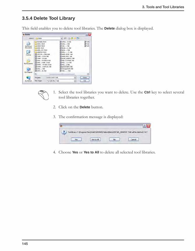
3. Tools and Tool Libraries
145
3.5.4 Delete Tool Library
This field enables you to delete tool libraries. The Delete dialog box is displayed.
1. Select the tool libraries you want to delete. Use the Ctrl key to select several tool libraries together.
2. Click on the Delete button.
3. The confirmation message is displayed:
4. Choose Yes or Yes to All to delete all selected tool libraries.
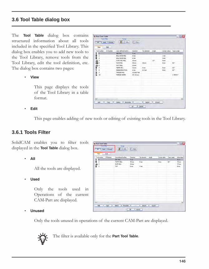
146
3.6 Tool Table dialog box
The Tool Table dialog box contains structured information about all tools included in the specified Tool Library. This dialog box enables you to add new tools to the Tool Library, remove tools from the Tool Library, edit the tool definition, etc. The dialog box contains two pages:
• View
This page displays the tools of the Tool Library in a table format.
• Edit
This page enables adding of new tools or editing of existing tools in the Tool Library.
3.6.1 Tools Filter
SolidCAM enables you to filter tools displayed in the Tool Table dialog box.
• All
All the tools are displayed.
• Used
Only the tools used in Operations of the current CAM-Part are displayed.
• Unused
Only the tools unused in operations of the current CAM-Part are displayed.
The filter is available only for the Part Tool Table.

3. Tools and Tool Libraries
147
3.6.2 Tool range
If you work with large tool libraries, you can use this option to reduce the number of tools displayed. You can also search the tool table for tools that match your criteria.
In the Range dialog box, enter the required properties of the tool. Enter only values that are different; leave the other fields unchanged.
The User-defined tool type section enables you to choose the type of tools you would like to have listed in the tool library.
The Rough tools only and Do not display rough tools options enable you to handle Rough tools (see topic 3.6.5) during the tools sorting.
• The Rough tools only option enables you to display only rough tools in the tools list.
• When the Do not display rough tools check box is selected, the tools marked as Rough are not displayed.
The Tool number section lists results according to the tool numbers.
The Diameter section enables you to choose the range using the diameter of the tools you would like to have listed in the tool library. If, for example, you would like to list the tools with a diameter from 1 to 16, enter 1 in the From box and 16 in the To box.
The Number of flutes section enables you to choose the range using the number of flutes of the tools you would like to have listed in the tool library. If, for example, you would like to list the tools with 1 to 4 flutes, enter 1 in the From box and 4 in the To box.
The Pitch section enables you to choose the range using the pitch of the tap tools you would like to have listed in the tool library. If, for example, you would like to list the tap tools with the Pitch from 0.5 to 1.5, enter 0.5 in the From box and 1.5 in the To box.
The Arbor diameter section enables you to choose the range using the arbor diameter of the tools you would like to have listed in the tool library. If, for example, you would like to list the tools with an arbor diameter from 1 to 16, enter 1 in the From box and 16 in the To box.
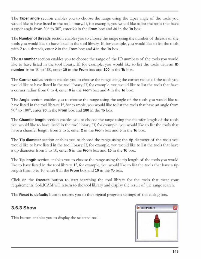
148
The Taper angle section enables you to choose the range using the taper angle of the tools you would like to have listed in the tool library. If, for example, you would like to list the tools that have a taper angle from 20° to 30°, enter 20 in the From box and 30 in the To box.
The Number of threads section enables you to choose the range using the number of threads of the tools you would like to have listed in the tool library. If, for example, you would like to list the tools with 2 to 4 threads, enter 2 in the From box and 4 in the To box.
The ID number section enables you to choose the range of the ID numbers of the tools you would like to have listed in the tool library. If, for example, you would like to list the tools with an ID number from 10 to 100, enter 10 in the From box and 100 in the To box.
The Corner radius section enables you to choose the range using the corner radius of the tools you would like to have listed in the tool library. If, for example, you would like to list the tools that have a corner radius from 0 to 4, enter 0 in the From box and 4 in the To box.
The Angle section enables you to choose the range using the angle of the tools you would like to have listed in the tool library. If, for example, you would like to list the tools that have an angle from 90° to 180°, enter 90 in the From box and 180 in the To box.
The Chamfer length section enables you to choose the range using the chamfer length of the tools you would like to have listed in the tool library. If, for example, you would like to list the tools that have a chamfer length from 2 to 5, enter 2 in the From box and 5 in the To box.
The Tip diameter section enables you to choose the range using the tip diameter of the tools you would like to have listed in the tool library. If, for example, you would like to list the tools that have a tip diameter from 5 to 10, enter 5 in the From box and 10 in the To box.
The Tip length section enables you to choose the range using the tip length of the tools you would like to have listed in the tool library. If, for example, you would like to list the tools that have a tip length from 5 to 10, enter 5 in the From box and 10 in the To box.
Click on the Execute button to start searching the tool library for the tools that meet your requirements. SolidCAM will return to the tool library and display the result of the range search.
The Reset to defaults button returns you to the original program settings of this dialog box.
3.6.3 Show
This button enables you to display the selected tool.
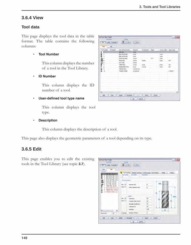
3. Tools and Tool Libraries
149
3.6.4 View
Tool data
This page displays the tool data in the table format. The table contains the following columns:
• ToolNumber
This column displays the number of a tool in the Tool Library.
• IDNumber
This column displays the ID number of a tool.
• User-definedtooltypename
This column displays the tool type.
• Description
This column displays the description of a tool.
This page also displays the geometric parameters of a tool depending on its type.
3.6.5 Edit
This page enables you to edit the existing tools in the Tool Library (see topic 3.7).
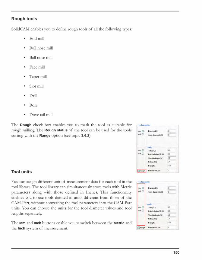
150
Rough tools
SolidCAM enables you to define rough tools of all the following types:
• End mill
• Bull nose mill
• Ball nose mill
• Face mill
• Taper mill
• Slot mill
• Drill
• Bore
• Dove tail mill
The Rough check box enables you to mark the tool as suitable for rough milling. The Rough status of the tool can be used for the tools sorting with the Range option (see topic 3.6.2).
Tool units
You can assign different unit of measurement data for each tool in the tool library. The tool library can simultaneously store tools with Metric parameters along with those defined in Inches. This functionality enables you to use tools defined in units different from those of the CAM-Part, without converting the tool parameters into the CAM-Part units. You can choose the units for the tool diameter values and tool lengths separately.
The Mm and Inch buttons enable you to switch between the Metric and the Inch system of measurement.

3. Tools and Tool Libraries
151
When a tool library created in a previous SolidCAM version is loaded, the following message is displayed:
When you confirm this message, the Assign Units dialog box is displayed so that you can assign units for tools.
Angular dimensions
The button appears in the parameters with angular values.
By clicking this button, you can switch the angle value from the degrees/minutes/seconds format to the decimal format and vice versa. In the first case, the edit box that displays the value is disabled.
When the value is displayed as a decimal, the edit box is available, and the value can be edited.
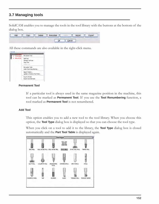
152
3.7 Managing tools
SolidCAM enables you to manage the tools in the tool library with the buttons at the bottom of the dialog box.
All these commands are also available in the right-click menu.
Permanent Tool
If a particular tool is always used in the same magazine position in the machine, this tool can be marked as Permanent Tool. If you use the Tool Renumbering function, a tool marked as Permanent Tool is not renumbered.
Add Tool
This option enables you to add a new tool to the tool library. When you choose this option, the Tool Type dialog box is displayed so that you can choose the tool type.
When you click on a tool to add it to the library, the Tool Type dialog box is closed automatically and the Part Tool Table is displayed again.

3. Tools and Tool Libraries
153
Change tool type
This option enables you to add the type of the existing tool. When you choose this option, the Tool Type dialog box is displayed so that you can choose the required tool type.
Copy Tool
This option enables you to create a copy of an existing tool.
Delete Tool
This option enables you to delete the selected tool.
Renumber Tools
This option enables you to perform automatic tool renumbering.
When the tool numbers in the list are not sequential increments of 1, this option enables you to renumber the tools sequentially by increments of 1. The tools can also be renumbered starting from a specific number that you choose.
1. Right-click on a tool in the list and choose the Renumber Tools command, from the menu, or click on the Renumber button at the bottom of the dialog box.
2. You are prompted to enter a new number for the first tool.
The Sort by option enables you to assign numbers to tools according to the operation sequence or the Tool sequence.
When you confirm the Tools Renumbering dialog box, the tools are renumbered accordingly, starting from the number of the first tool.

154
3. Recalculate the CAM-Part. The CAM-Part must be recalculated to ensure that the GCode contains the correct tool number for each operation.
A tool marked as Permanent tool is not renumbered.
Import Tool
This option enables you to import tools to the Tool Library from the Current Tool Library or any other Tool Library. The Tool Libraries list is displayed. The Current Tool Library, which is the first in the list, is automatically chosen.
You can choose the location of the Tool Libraries for the tools import.
The Library name box enables you to choose the Tool table for the tools import.
The File type box enables you to import tools from SolidCAM Tool libraries, Excel files and from CSV files.
If the Current Tool Library is defined, it is automatically chosen as a source for tool import.
The Tool list displays all the tools contained in the specified tool library. The right-click menu is available.
The Copy to Table option imports the selected tools to the Tool Library. To import all tools from the list, click Copy all to Table.
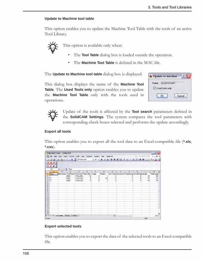
3. Tools and Tool Libraries
155
Update to Machine tool table
This option enables you to update the Machine Tool Table with the tools of an active Tool Library.
This option is available only when:
• The Tool Table dialog box is loaded outside the operation.
• The Machine Tool Table is defined in the MAC file.
The Update to Machine tool table dialog box is displayed.
This dialog box displays the name of the Machine Tool Table. The Used Tools only option enables you to update the Machine Tool Table only with the tools used in operations.
Update of the tools is affected by the Tool search parameters defined in the SolidCAM Settings. The system compares the tool parameters with corresponding check boxes selected and performs the update accordingly.
Export all tools
This option enables you to export all the tool data to an Excel-compatible file (*.xls, *.csv).
Export selected tools
This option enables you to export the data of the selected tools to an Excel-compatible file.

156
3.8 Tool data
SolidCAM enables you to define the Tool with the following data:
• Geometric parameters;
• Tool material;
• Feed and Spin defaults;
• Tool holder.
The Tool Data area displays the parameters of the selected tool.
Tool definition
Speed and Feed Tool Holder Geometry definition
H
L
R
D
Tool material

3. Tools and Tool Libraries
157
The Tool Topology page contains the Topology data of the tool, such as diameter, length, angle, corner radius, etc.
The Default Tool Data page contains the default Tool Material data, Feed and Spin data and diameter and length offset numbers.
The Tool Message page contains fields, in which user messages are entered.
The Tool Coolant page enables you to choose the coolant options that will be used by default for the current tool.
The Holder page enables you to define the tool holder by choosing it from the global or local tool table and specifying the related parameters.
The Shape page enables you to choose a shaped tool for the operation.
3.8.1 Tool Topology page
Tool number
The Tool number is a numerical identifier of the tool, i.e. the numerical name of the tool, whose value has to be an integer. It enables you to define tool numbers according to the numbering system that you are used to. The Tool number is used in the GCode when the tool changes, the tool length and radius values for tool compensation (G4x) are read from the machine controller.
The Max_Tool_Number parameter in the MAC file defines the total number of tools that can be defined. In other words, this parameter defines the capacity of the cutter magazine of your CNC-machine.

158
SolidCAM checks the total number of tools in the Part Tool Table during the following operations:
• Adding, copying or importing tools;
• Loading the CAM-Part;
• Inserting Machining Process;
• Creating new tools by AFRM.
When the total number of tools exceeds the Max_Tool_Number, SolidCAM displays an error message.
The Tools in list field displays the total number of tools defined in the Tool Library.
ID number
You can use any number, e.g. the catalog number of the tool to facilitate its identification.
When a new tool is defined, SolidCAM sets the Tool number to the first unused number. This default Tool number can be changed. When you change the Tool number, make a note that this parameter has to be unique for each tool.
If a particular tool always has the same number and cannot be changed, this tool can be marked as Permanent. For example, when the Tool number represents the number of a tool magazine pocket used for the tool, the Permanent mark means that the tool is always located in this pocket.
If you use the Tool Renumbering function (see topic 3.7), a tool marked as Permanent is not renumbered.
Diameter
This field defines the cutting diameter of the tool.
Corner Radius/Angle
When the tool type is End mill/Ball nose mill/Bull nose mill, the Corner Radius field is displayed. When the tool type is Drill, the Angle field is displayed.
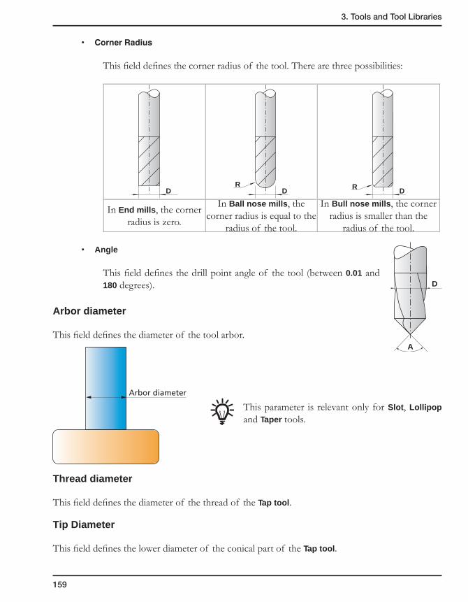
3. Tools and Tool Libraries
159
• CornerRadius
This field defines the corner radius of the tool. There are three possibilities:
D DR
DR
In End mills, the corner radius is zero.
In Ball nose mills, the corner radius is equal to the
radius of the tool.
In Bull nose mills, the corner radius is smaller than the
radius of the tool.
• Angle
This field defines the drill point angle of the tool (between 0.01 and 180 degrees).
Arbor diameter
This field defines the diameter of the tool arbor.
This parameter is relevant only for Slot, Lollipop and Taper tools.
Thread diameter
This field defines the diameter of the thread of the Tap tool.
Tip Diameter
This field defines the lower diameter of the conical part of the Tap tool.
D
A
Arbor diameter

160
Chamfer length
This field defines the length of the conical part of the Tap tool.
Pitch
This field defines the pitch of the Tap tool. The Pitch is the distance between corresponding vertices of adjacent teeth of a thread.
The Thread diameter, Tip diameter, Chamfer length and Pitch parameters are relevant only for Tap tools.
Length
This field defines the length of the tool. In milling calculations, the system does not use this data; the length of the tool is only the output to the GCode file.
• Total
The total tool length.
• Outside Holder
The length of the tool outside the tool holder.
• Cutting
The length of the cutting part of the tool.
Cutting Length
Total Length
Outside Holder Length
Thread Diameter
Tip Diameter
ChamferLength
TotalLength
CuttingLength
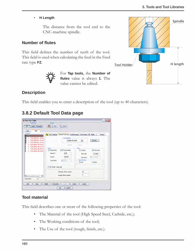
3. Tools and Tool Libraries
161
• H Length
The distance from the tool end to the CNC-machine spindle.
Number of flutes
This field defines the number of teeth of the tool. This field is used when calculating the feed in the Feed rate type FZ.
For Tap tools, the Number of flutes value is always 1. The value cannot be edited.
Description
This field enables you to enter a description of the tool (up to 40 characters).
3.8.2 Default Tool Data page
Tool material
This field describes one or more of the following properties of the tool:
• The Material of the tool (High Speed Steel, Carbide, etc.);
• The Working conditions of the tool;
• The Use of the tool (rough, finish, etc.).
H lengthTool Holder
Spindle
162
The Tool material is used to define the Speed and Feed defaults.
When you choose the Tool material, the feed type is changed to FZ and the spin type to V. The Feed and Spin values are default system values since the Work material has not been defined yet. Loading the tool to an operation connects the Tool material to the Work material and the correct Feed and Spin values are loaded from the Speed/Feed defaults table.
For Tap tools, the FZ value does not depend on the Tool Material. The Spin Rate value can be customized for different Tool Materials. In this case, changing the Tool Material changes the Spin Rate. Since the Spin Rate value is part of the formula of the F calculation, the F parameter value has to be recalculated.
Spin
This field defines the spinning speed of the tool. It defines two spin values:
• Spin Rate – Normal spin rate; used in rough milling.
• Spin Finish – Finish spin rate; used in finish milling.
The Spin finish check box enables you to optionally define different values for Spin rate and Spin finish. When this check box is selected, the corresponding edit box is available so that you can edit its value. When this check box is not selected, the specified Spin rate value is used for both rough and finish machining.
For Drill and Tap tools, the Spin Finish parameter is not relevant.
The spin value can be defined in two types of units: S and V.
S is the default and it signifies Revolutions per Minute. V signifies Material cutting speed in Meters/Minute in the Metric system or in Feet/Minute in the Inch system; it is calculated according to the following formula:
V = (S * PI * Tool Diameter) / 1000 (for the Metric system);
V = (S * PI * Tool Diameter) / 12 (for the Inch system).
Feed
This field defines the feed rate of the tool. It defines three feed values:
• Feed XY – Feed rate in the XY plane.
• Feed Z – Feed rate in the Z direction.
• Feed Finish – Feed rate used for finish milling.

3. Tools and Tool Libraries
163
The Feed finish check box enables you to optionally define different values for Feed XY and Feed finish. When this check box is selected, the corresponding edit box is available so that you can edit its value. When this check box is not selected, the specified Feed XY value is used for both rough and finish machining.
For Drill and Tap tools, the Feed XY and Feed Finish parameters are not relevant.
The feed value can be defined in two types of units: F and FZ.
F is the default and it signifies Units per minute. FZ signifies Units per tooth and is calculated according to the following formula:
FZ = F/(Number of Flutes * S)
For Tap tools, SolidCAM automatically calculates Feed Z (F and FZ) according to the following formulas:
F=Spin Rate * Pitch
FZ=Pitch
Calculated values are displayed in Feed Z field. These values cannot be changed. The F/FZ buttons enable you to check the parameter values.
3D Model - entry only
When this check box is selected, the defined Feed Z is used for vertical movements only.
When this check box is not selected, the defined Feed Z is used for all movements when the Z-coordinate changes.
This option is available only for 3D Milling operations.
Diameter offset number
This parameter defines the number of the Diameter Offset Register of the current tool in the Offset table of the CNC-machine.
Length offset number
This parameter defines the number of the Length Offset Register of the current tool in the Offset table of the CNC-machine.
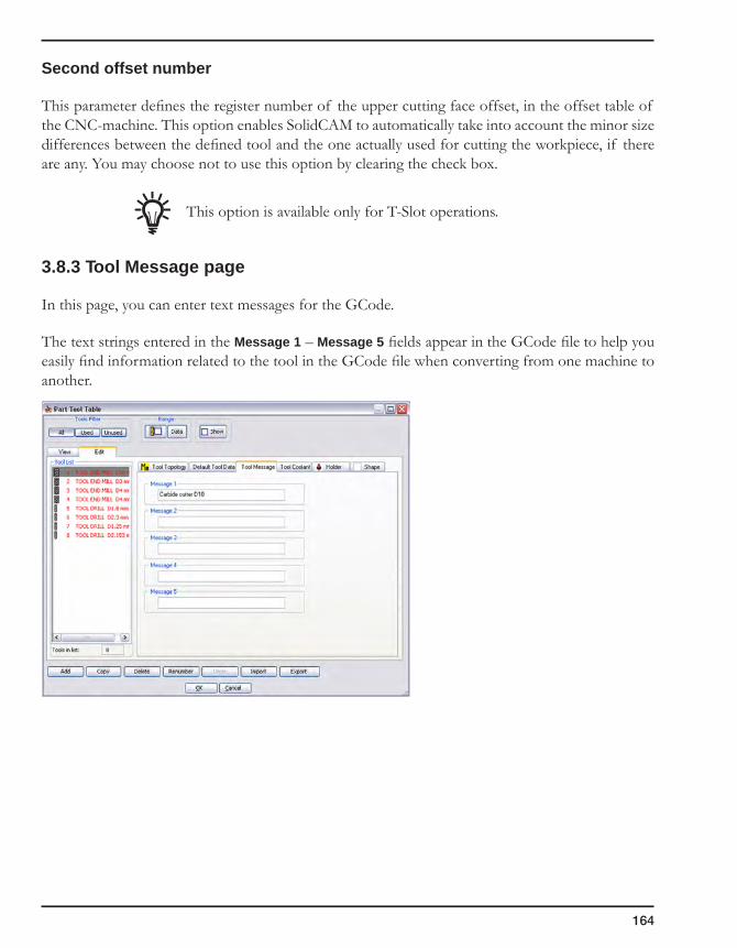
164
Second offset number
This parameter defines the register number of the upper cutting face offset, in the offset table of the CNC-machine. This option enables SolidCAM to automatically take into account the minor size differences between the defined tool and the one actually used for cutting the workpiece, if there are any. You may choose not to use this option by clearing the check box.
This option is available only for T-Slot operations.
3.8.3 Tool Message page
In this page, you can enter text messages for the GCode.
The text strings entered in the Message 1 – Message 5 fields appear in the GCode file to help you easily find information related to the tool in the GCode file when converting from one machine to another.
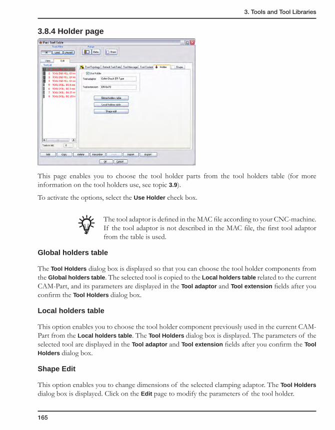
3. Tools and Tool Libraries
165
3.8.4 Holder page
This page enables you to choose the tool holder parts from the tool holders table (for more information on the tool holders use, see topic 3.9).
To activate the options, select the Use Holder check box.
The tool adaptor is defined in the MAC file according to your CNC-machine. If the tool adaptor is not described in the MAC file, the first tool adaptor from the table is used.
Global holders table
The Tool Holders dialog box is displayed so that you can choose the tool holder components from the Global holders table. The selected tool is copied to the Local holders table related to the current CAM-Part, and its parameters are displayed in the Tool adaptor and Tool extension fields after you confirm the Tool Holders dialog box.
Local holders table
This option enables you to choose the tool holder component previously used in the current CAM-Part from the Local holders table. The Tool Holders dialog box is displayed. The parameters of the selected tool are displayed in the Tool adaptor and Tool extension fields after you confirm the Tool Holders dialog box.
Shape Edit
This option enables you to change dimensions of the selected clamping adaptor. The Tool Holders dialog box is displayed. Click on the Edit page to modify the parameters of the tool holder.

166
3.8.5 Tool Coolant page
This page enables you to choose the coolant options that will be used by default for the current tool.
When a tool is chosen for use in a specific operation, the default coolant options are automatically applied to the tool use in this operation. The tool coolant options can be changed for each operation.
All the existing coolant types are listed with corresponding check boxes. When a check box is selected, the related coolant option is used.
The coolant options available for use on the current CNC-machine, according to the MAC-file settings, are marked with asterisks (*).
The Minimum Quantity Lubrication edit box is enabled only when the corresponding check box is selected. The default value of this parameter is 0; the possible values are integers in the range from 0 to 99999. When the entered value is out of range, the error message is displayed.
When a new tool is defined, it is assigned the default tool coolant options according to the following rules:
• When a tool is created in the Part Tool Table, it is assigned the options according to the Part Settings.
• When a new tool is defined not in context of CAM-Part (all the tool tables except for the Part Tool Table), it is assigned the options according to the SolidCAM Settings.
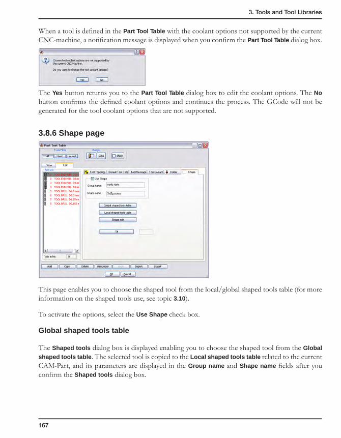
3. Tools and Tool Libraries
167
When a tool is defined in the Part Tool Table with the coolant options not supported by the current CNC-machine, a notification message is displayed when you confirm the Part Tool Table dialog box.
The Yes button returns you to the Part Tool Table dialog box to edit the coolant options. The No button confirms the defined coolant options and continues the process. The GCode will not be generated for the tool coolant options that are not supported.
3.8.6 Shape page
This page enables you to choose the shaped tool from the local/global shaped tools table (for more information on the shaped tools use, see topic 3.10).
To activate the options, select the Use Shape check box.
Global shaped tools table
The Shaped tools dialog box is displayed enabling you to choose the shaped tool from the Global shaped tools table. The selected tool is copied to the Local shaped tools table related to the current CAM-Part, and its parameters are displayed in the Group name and Shape name fields after you confirm the Shaped tools dialog box.
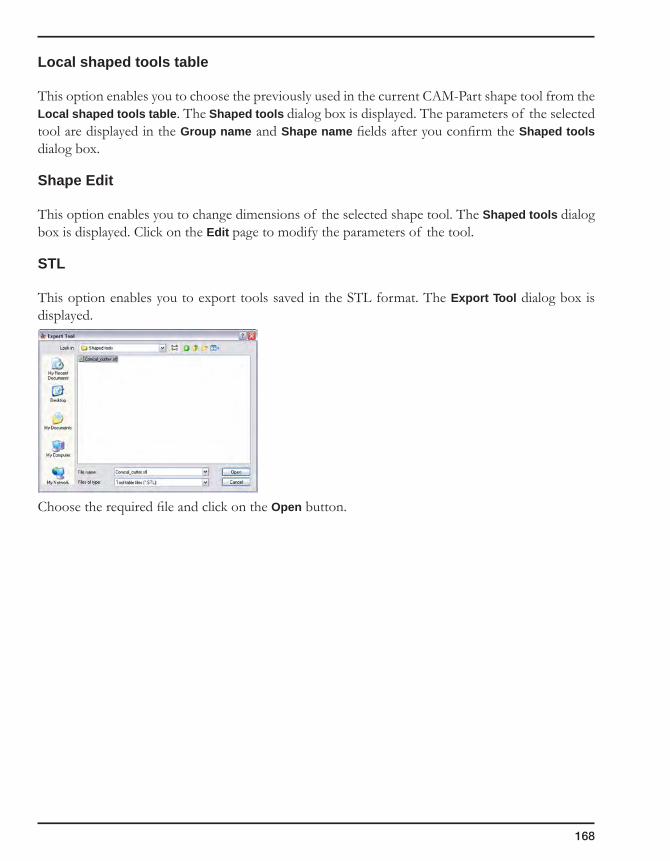
168
Local shaped tools table
This option enables you to choose the previously used in the current CAM-Part shape tool from the Local shaped tools table. The Shaped tools dialog box is displayed. The parameters of the selected tool are displayed in the Group name and Shape name fields after you confirm the Shaped tools dialog box.
Shape Edit
This option enables you to change dimensions of the selected shape tool. The Shaped tools dialog box is displayed. Click on the Edit page to modify the parameters of the tool.
STL
This option enables you to export tools saved in the STL format. The Export Tool dialog box is displayed.
Choose the required file and click on the Open button.
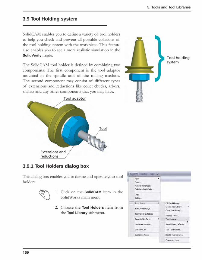
3. Tools and Tool Libraries
169
3.9 Tool Holding system
SolidCAM enables you to define a variety of tool holders to help you check and prevent all possible collisions of the tool holding system with the workpiece. This feature also enables you to see a more realistic simulation in the SolidVerify mode.
The SolidCAM tool holder is defined by combining two components. The first component is the tool adaptor mounted in the spindle unit of the milling machine. The second component may consist of different types of extensions and reductions like collet chucks, arbors, shanks and any other components that you may have.
3.9.1 Tool Holders dialog box
This dialog box enables you to define and operate your tool holders.
1. Click on the SolidCAM item in the SolidWorks main menu.
2. Choose the Tool Holders item from the Tool Library submenu.
} Tool holding system
Tool adaptor
Extensions andreductions
Tool

170
3. The Tool Holders dialog box is displayed. A CAD model file is also displayed so that you can define the geometry of the new holders.
Tool holder component tables
The first list displayed above enables you to define and manage your tool adaptors.
1. Right-click on the item name in the table.
2. Choose a command from the submenu.
• AddHolderComponent
This option enables you to define the geometry of the new tool adaptor that will be added to the table. The Holder Geometry dialog box is displayed.
• Generate
This option generates the sketch in the model file with the geometry of the selected tool adaptor.
• Replace
This option enables you to replace the existing tool adaptor geometry with a new one. The Holder Geometry dialog box is displayed. Select the new geometry.
• Delete
This option enables you to remove the tool adaptor part from the list.
• Rename
This option enables you to assign a new name to the tool adaptor.
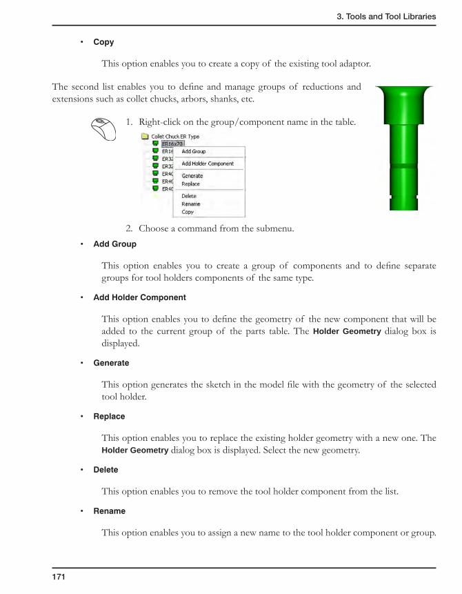
3. Tools and Tool Libraries
171
• Copy
This option enables you to create a copy of the existing tool adaptor.
The second list enables you to define and manage groups of reductions and extensions such as collet chucks, arbors, shanks, etc.
1. Right-click on the group/component name in the table.
2. Choose a command from the submenu.• AddGroup
This option enables you to create a group of components and to define separate groups for tool holders components of the same type.
• AddHolderComponent
This option enables you to define the geometry of the new component that will be added to the current group of the parts table. The Holder Geometry dialog box is displayed.
• Generate
This option generates the sketch in the model file with the geometry of the selected tool holder.
• Replace
This option enables you to replace the existing holder geometry with a new one. The Holder Geometry dialog box is displayed. Select the new geometry.
• Delete
This option enables you to remove the tool holder component from the list.
• Rename
This option enables you to assign a new name to the tool holder component or group.

172
• Copy
This option enables you to create a copy of the existing tool holder component.
Description
SolidCAM enables you to type a brief description of the tool holder component (reduction or extension).
Show page
This page enables you to see a 3D model of the tool holder.
In the graphic area of this page you can rotate, zoom and pan the 3D model of the tool holder.
Use the following combinations:
• Middle mouse button – Rotation of tool holder
• Shift + Middle mouse button – Zoom of tool holder
• Ctrl + Middle mouse button – Pan of tool holder
Edit page
This page enables you to edit the parameters of the selected tool holder component.
1. Select the tool holder component.
2. Switch to the Edit page to change the dimensions of the tool holder component.
The interactive picture of the selected tool holder component is displayed. The parameters pages are located below the picture.
SolidCAM divides the tool holder component into solid segments like cylinders, cones or toruses. For each solid primitive, SolidCAM determines the actual dimensions.
For more information on this subject, see topic 3.9.3.
You can change the dimensions of each segment with its specific page.
1. Select the segment on the picture or through the tabs below the picture.
2. Type the new value of the parameter in the value field.

3. Tools and Tool Libraries
173
3.9.2 Tool Holder Geometry definition
This dialog box enables you to define the geometry of the tool holder component.
Define chain
This option enables you to define a new chain of the component geometry. The Chain Options dialog box is displayed. In the model file displayed, you can sketch the shape of half the tool holder component and then define the chain. The direction of the chain does not matter.
Note that the left side of the sketch is the bottom of the tool holder component and the right side is the top.
Replace chain
This command enables you to replace a chain in the current chain geometry.
Edit chain
This command enables you to update a chain in the current chain geometry.
Reference point
This option enables you to define the reference point through which the rotation axis of the tool holder component passes.
3.9.3 Tool Holder segments
SolidCAM determines three types of segments of the Holder Geometry.
Cylinder
• Diameter
• Height
Diameter
Height
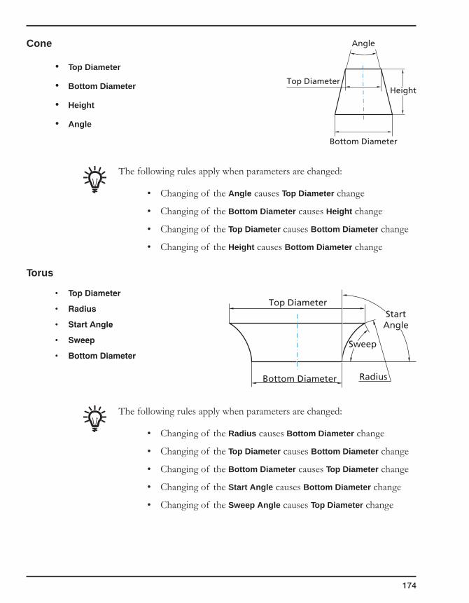
174
Cone
• Top Diameter
• Bottom Diameter
• Height
• Angle
The following rules apply when parameters are changed:
• Changing of the Angle causes Top Diameter change
• Changing of the Bottom Diameter causes Height change
• Changing of the Top Diameter causes Bottom Diameter change
• Changing of the Height causes Bottom Diameter change
Torus
• TopDiameter
• Radius
• StartAngle
• Sweep
• BottomDiameter
The following rules apply when parameters are changed:
• Changing of the Radius causes Bottom Diameter change
• Changing of the Top Diameter causes Bottom Diameter change
• Changing of the Bottom Diameter causes Top Diameter change
• Changing of the Start Angle causes Bottom Diameter change
• Changing of the Sweep Angle causes Top Diameter change
Top Diameter
Angle
Height
Bottom Diameter
Top DiameterStart
Angle
Sweep
RadiusBottom Diameter
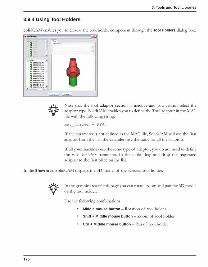
3. Tools and Tool Libraries
175
3.9.4 Using Tool Holders
SolidCAM enables you to choose the tool holder component through the Tool Holders dialog box.
Note that the tool adaptor section is inactive and you cannot select the adaptor type. SolidCAM enables you to define the Tool adaptor in the MAC file with the following string:
mac_holder = BT45
If the parameter is not defined in the MAC file, SolidCAM will use the first adaptor from the list; the extenders are the same for all the adaptors.
If all your machines use the same type of adaptor, you do not need to define the mac_holder parameter. In the table, drag and drop the requested adaptor to the first place on the list.
In the Show area, SolidCAM displays the 3D model of the selected tool holder.
In the graphic area of this page you can rotate, zoom and pan the 3D model of the tool holder.
Use the following combinations:
• Middle mouse button – Rotation of tool holder
• Shift + Middle mouse button – Zoom of tool holder
• Ctrl + Middle mouse button – Pan of tool holder
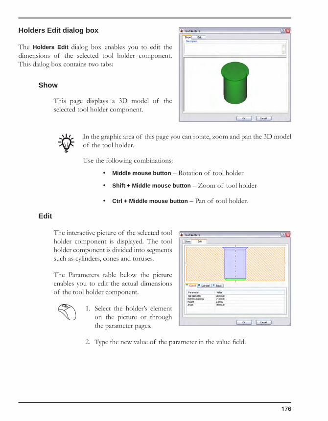
176
Holders Edit dialog box
The Holders Edit dialog box enables you to edit the dimensions of the selected tool holder component. This dialog box contains two tabs:
Show
This page displays a 3D model of the selected tool holder component.
In the graphic area of this page you can rotate, zoom and pan the 3D model of the tool holder.
Use the following combinations:
• Middle mouse button – Rotation of tool holder
• Shift + Middle mouse button – Zoom of tool holder
• Ctrl + Middle mouse button – Pan of tool holder.
Edit
The interactive picture of the selected tool holder component is displayed. The tool holder component is divided into segments such as cylinders, cones and toruses.
The Parameters table below the picture enables you to edit the actual dimensions of the tool holder component.
1. Select the holder’s element on the picture or through the parameter pages.
2. Type the new value of the parameter in the value field.
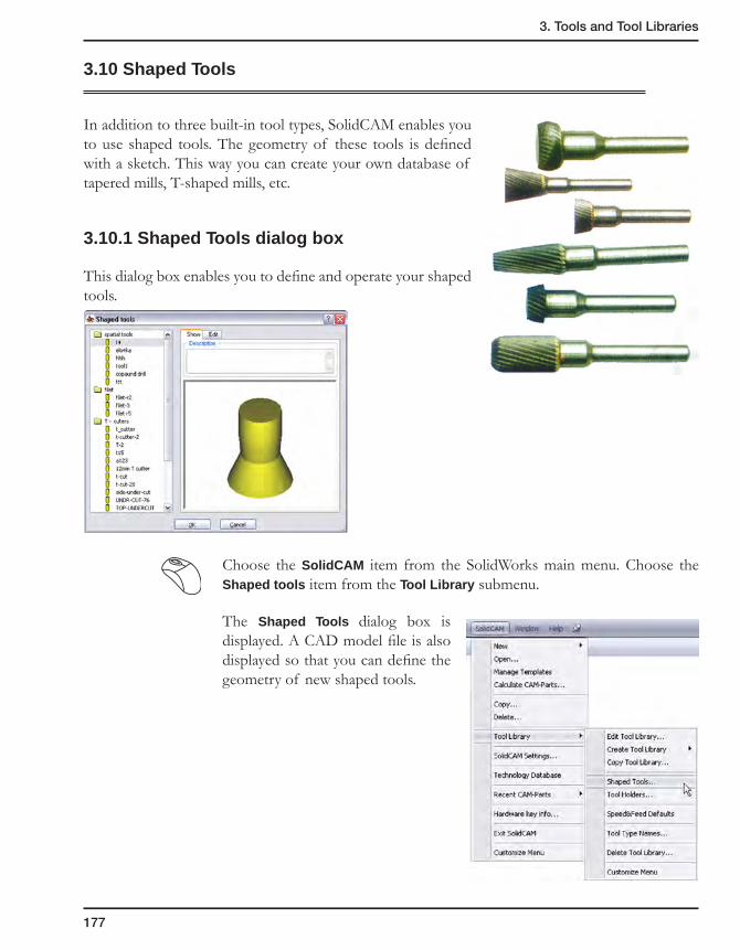
3. Tools and Tool Libraries
177
3.10 Shaped Tools
In addition to three built-in tool types, SolidCAM enables you to use shaped tools. The geometry of these tools is defined with a sketch. This way you can create your own database of tapered mills, T-shaped mills, etc.
3.10.1 Shaped Tools dialog box
This dialog box enables you to define and operate your shaped tools.
Choose the SolidCAM item from the SolidWorks main menu. Choose the Shaped tools item from the Tool Library submenu.
The Shaped Tools dialog box is displayed. A CAD model file is also displayed so that you can define the geometry of new shaped tools.
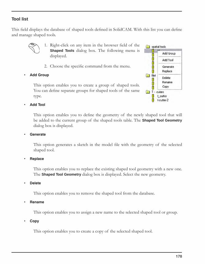
178
Tool list
This field displays the database of shaped tools defined in SolidCAM. With this list you can define and manage shaped tools.
1. Right-click on any item in the browser field of the Shaped Tools dialog box. The following menu is displayed.
2. Choose the specific command from the menu.
• AddGroup
This option enables you to create a group of shaped tools. You can define separate groups for shaped tools of the same type.
• AddTool
This option enables you to define the geometry of the newly shaped tool that will be added to the current group of the shaped tools table. The Shaped Tool Geometry dialog box is displayed.
• Generate
This option generates a sketch in the model file with the geometry of the selected shaped tool.
• Replace
This option enables you to replace the existing shaped tool geometry with a new one. The Shaped Tool Geometry dialog box is displayed. Select the new geometry.
• Delete
This option enables you to remove the shaped tool from the database.
• Rename
This option enables you to assign a new name to the selected shaped tool or group.
• Copy
This option enables you to create a copy of the selected shaped tool.

3. Tools and Tool Libraries
179
Description
You can place a brief description of the shaped tool here.
Show page
This page displays a 3D model of the selected shaped tool.
In the graphic area of this page you can rotate, zoom and pan the 3D model of the shaped tool.
Use the following combinations:
• Middle mouse button – Rotation of tool
• Shift + Middle mouse button – Zoom of tool
• Ctrl + Middle mouse button – Pan of tool
Edit page
This page enables you to edit the parameters of the selected shaped tool.
1. Select the Shaped tool.
2. Switch to the Edit page to change the shaped tool dimensions.
The interactive picture of the selected shaped tool is displayed. The parameters pages are located below the picture.
SolidCAM divides the tool into solid segments like cylinders, cones or toruses. For each solid primitive, SolidCAM determines actual dimensions.
You can change the dimensions of each segment in its specific page.
1. Select the tool’s element on the picture or through the parameter pages.
2. Type the new value of the parameter in the Value field.
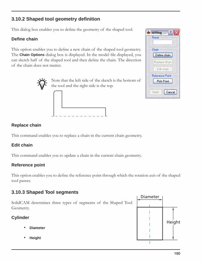
180
3.10.2 Shaped tool geometry definition
This dialog box enables you to define the geometry of the shaped tool.
Define chain
This option enables you to define a new chain of the shaped tool geometry. The Chain Options dialog box is displayed. In the model file displayed, you can sketch half of the shaped tool and then define the chain. The direction of the chain does not matter.
Note that the left side of the sketch is the bottom of the tool and the right side is the top.
Replace chain
This command enables you to replace a chain in the current chain geometry.
Edit chain
This command enables you to update a chain in the current chain geometry.
Reference point
This option enables you to define the reference point through which the rotation axis of the shaped tool passes.
3.10.3 Shaped Tool segments
SolidCAM determines three types of segments of the Shaped Tool Geometry.
Cylinder
• Diameter
• Height
Diameter
Height

3. Tools and Tool Libraries
181
Cone
• Top Diameter
• Bottom Diameter
• Height
• Angle
The following rules apply when parameters are changed:
• Changing of the Angle causes Top Diameter change.
• Changing of the Bottom Diameter causes Height change.
• Changing of the Top Diameter causes Bottom Diameter change.
• Changing of the Height causes Bottom Diameter change
Torus
• TopDiameter
• Radius
• StartAngle
• Sweep
• BottomDiameter
The following rules apply when parameters are changed:
• Changing of the Radius causes Bottom Diameter change
• Changing of the Top Diameter causes Bottom Diameter change
• Changing of the Bottom Diameter causes Top Diameter change
• Changing of the Start Angle causes Bottom Diameter change
• Changing of the Sweep Angle causes Top Diameter change
Top Diameter
Angle
Height
Bottom Diameter
Top DiameterStart
Angle
Sweep
RadiusBottom Diameter

182
3.10.4 Using Shaped tools
SolidCAM enables you to choose the specific shaped tool using the Shaped tools dialog box.
In the Show area, SolidCAM displays the 3D model of the selected tool.
In the graphic area of this page you can rotate, zoom and pan the 3D model of the tool.
Use the following combinations:
• Middle mouse button - Rotation of tool
• Shift + Middle mouse button - Zoom of tool
• Ctrl + Middle mouse button - Pan of tool
Shape edit
The Edit page of the Shaped tools dialog box enables you to edit the dimensions of the selected tool.
This dialog box contains two pages:
Show
This page displays a 3D model of the selected tool.
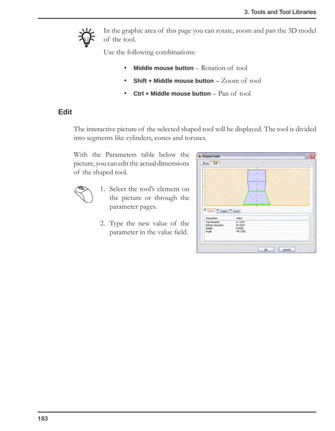
3. Tools and Tool Libraries
183
In the graphic area of this page you can rotate, zoom and pan the 3D model of the tool.
Use the following combinations:
• Middle mouse button – Rotation of tool
• Shift + Middle mouse button – Zoom of tool
• Ctrl + Middle mouse button – Pan of tool
Edit
The interactive picture of the selected shaped tool will be displayed. The tool is divided into segments like cylinders, cones and toruses.
With the Parameters table below the picture, you can edit the actual dimensions of the shaped tool.
1. Select the tool’s element on the picture or through the parameter pages.
2. Type the new value of the parameter in the value field.

184
3.11 Feed and Speed defaults
The Speed/Feed Default option enables the program to calculate the speed and feed rate according to the Work material and Tool material you are using.
Choose the Speed&Feed Defaults item from the Tool Library submenu.
The Speed/Feed Default dialog box is displayed.
This dialog box enables you to define the Work Material and the Tool Material and to define the different values of the Speed and Feed for each combination set. The dialog box shows the tree-control list of the existing Tool and Work Materials. The root items of the tree are the Tool Materials; for each tool material you can see the list of the Work Materials for which Speed/Feed default is defined. The right area of the dialog box shows the Speed/Feed parameters for each selected pair of Tool material and Work material.
Work MaterialTool Material
Speed/Feed Defaults
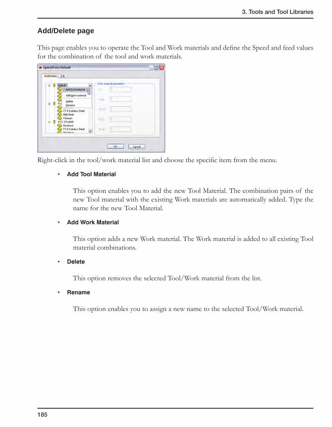
3. Tools and Tool Libraries
185
Add/Delete page
This page enables you to operate the Tool and Work materials and define the Speed and feed values for the combination of the tool and work materials.
Right-click in the tool/work material list and choose the specific item from the menu.
• AddToolMaterial
This option enables you to add the new Tool Material. The combination pairs of the new Tool material with the existing Work materials are automatically added. Type the name for the new Tool Material.
• AddWorkMaterial
This option adds a new Work material. The Work material is added to all existing Tool material combinations.
• Delete
This option removes the selected Tool/Work material from the list.
• Rename
This option enables you to assign a new name to the selected Tool/Work material.

186
Work material parameters
In this area, you have to assign the Speed and Feed values for the selected Tool/Work material combination.
SolidCAM enables you to define the following values:
• V Signifies the Rough Material cutting speed in Meters/Minute in the Metric system or in Feet/Minute in the Inch system.
• Vfin Signifies the Finish Material cutting speed in Meters/Minute in the Metric system or in Feet/Minute in the Inch system.
• FZXY Feed rate in the XY plane, in Units per tooth.• FZZ Feed rate in the Z direction, in Units per tooth.• FZfin Feed rate used for finish milling, in Units per tooth.
Edit page
This page enables you to edit the values of the Speed and Feed for each combination of the Tool/Work material.
Click on the parameter you have to change and enter the new value.

Defining a new Geometry
Drilling Geometry
3D Model Geometry
Wireframe Geometries
Managing Geometries
Geometry synchronization
4GeometryWhenever you work in CAD, you use 2D wireframe curves and 3D models to describe real life parts. With SolidCAM, you can turn these models into GCode for any CNC-machine.
A major step in the process from modeling to manufacturing is to tell SolidCAM what and where you want to machine. In SolidCAM, existing models are used to pass this information to the CAM module.

188
4.1 Introduction
SolidCAM enables you to turn 3D models, 2D and 3D sketches built with SolidWorks into GCode for any CNC-machine. In this process of modelling to manufacturing, geometries have to be defined to determine where the model will be machined.
In SolidCAM, you can define geometries in the operation dialog box; this enables SolidCAM to check if the geometry follows the necessary rules needed in this type of operation.
The geometries defined in SolidCAM are associative to the SolidWorks model. Any change made to the model or sketch will propagate to referenced SolidCAM geometry.
Geometry
Wireframe Drill
3D Model
Faces
Section
Limit
Slot
Working Area
Profile
3D

189
4. Geometry
4.2 Drilling geometry
A Drilling geometry consists of one or more points (drilling centers) that are defined by the X-, Y- and Z-values. They can be selected on models using a number of different methods.
4.2.1 Defining a Drilling geometry
In Drilling operations, you have to define the coordinate points where SolidCAM will execute the drilling cycles. The powerful selection tool enables you to define and edit drilling positions quickly and easily.
In the example above, the drilling points have been selected by their radius and Z-level on a 3D solid model. With automatic selection the distance between two drilling points is optimized to reduce machining time.
The button in the Geometry page of the Drilling Operation and Thread Milling Operation dialog boxes enables you to choose the mode of the geometry definition.
• The Plane mode enables you to define the geometry on the plane/face parallel to the XY-plane of the current CoordSys. Click on the Define button to display the Drill Geometry Selection dialog box (see topic 4.2.3).
• The Around 4th axis mode enables you to select the drilling geometry wrapped on the solid model around the 4th axis. The Define button displays the Around 4th Axis Drill Geometry Selection dialog box (see topic 4.2.4).
This method enables you to select only the holes whose axis intersects with the revolution axis of the CAM-Part.
This method can be chosen when the appropriate CoordSys that enables the use of the 4th axis is selected.
Revolution axis

190
4.2.2 Editing a Drilling geometry
You can add or remove drilling positions from previously saved drilling geometries.
1. In SolidCAM Manager, right-click on a Drill geometry and choose the Edit option from the menu.
2. The Drill Geometry Selection dialog box is displayed. With the Select/Unselect option, you can add or remove drilling points.
4.2.3 Drill Geometry Selection dialog box
For Drilling operations, you have to define the coordinate points where SolidCAM executes the drilling cycles.
The powerful selection tool enables you to define and edit drilling positions quickly and easily. Whenever you have to define a drilling geometry, the Drill Geometry Selection dialog box is displayed.
Name
This option enables you to define the name of the geometry. SolidCAM offers you the Default Geometry name (see topic 12.9) that can be edited.
Configurations
This option enables you to switch between SolidWorks configurations. Choose the necessary configuration for the geometry definition.
Select/Unselect drilling centers
Use the Select/Unselect mode to add and remove drilling positions from the geometry. The Undo/Redo button deletes or restores the last selection.

191
4. Geometry
All the selected points are shown in the list at the bottom of the dialog box. To remove a point from the list, right-click on the point name in the list and choose the Delete option from the menu or choose the Delete All option to remove all of the points.
Sequence of drill positions
You can change the sequence of drill positions in the list by dragging and dropping.
You can also define and edit the sequence of drill positions in the Drilling Operation dialog box (see topic 6.6.3).
Selecting modes (Select centers by)
You can add drilling positions to the current geometry using the following options:
• Pick position. You can define drilling positions one by one using the CAD point selection options. You can also type the coordinates into the X,Y,Z dialog box and confirm each drilling point by clicking on the Enter button.
1. Pick drilling center position – select the drilling point.
2. Confirm the selection by clicking on the Enter button.
• 3 Points on circumference. Usually, all curves and arcs of imported models are converted into splines by the exporting CAD system. Due to the nature of spline curves or surface boundaries, you cannot pick a center position like you could on a circle or arc. SolidCAM calculates the center position of an arc defined by three points positioned on the spline edges. This facilitates the selection of drilling centers on spline surfaces.
1. Pick the first point – pick a point on the circumference of the circle or arc using the CAD point selection options or type the coordinates into the X,Y,Z dialog box and confirm.
2. Pick the second point.
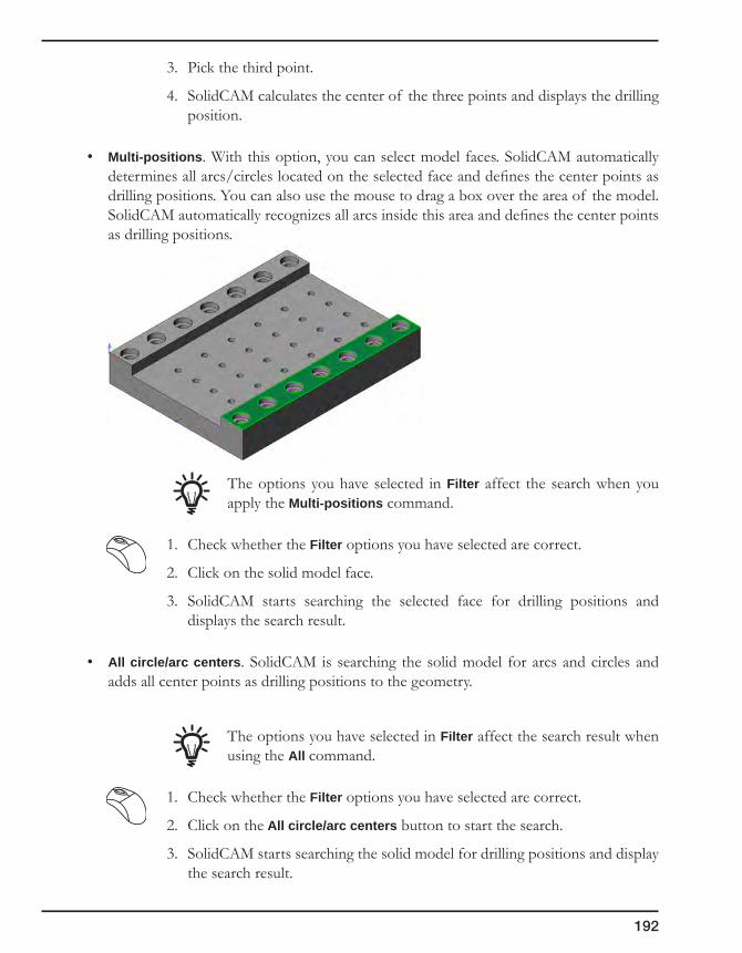
192
3. Pick the third point.
4. SolidCAM calculates the center of the three points and displays the drilling position.
• Multi-positions. With this option, you can select model faces. SolidCAM automatically determines all arcs/circles located on the selected face and defines the center points as drilling positions. You can also use the mouse to drag a box over the area of the model. SolidCAM automatically recognizes all arcs inside this area and defines the center points as drilling positions.
The options you have selected in Filter affect the search when you apply the Multi-positions command.
1. Check whether the Filter options you have selected are correct.
2. Click on the solid model face.
3. SolidCAM starts searching the selected face for drilling positions and displays the search result.
• All circle/arc centers. SolidCAM is searching the solid model for arcs and circles and adds all center points as drilling positions to the geometry.
The options you have selected in Filter affect the search result when using the All command.
1. Check whether the Filter options you have selected are correct.
2. Click on the All circle/arc centers button to start the search.
3. SolidCAM starts searching the solid model for drilling positions and display the search result.

193
4. Geometry
• CAD selection. SolidCAM enables you to select the drilling geometry with the SolidWorks selection tools.
1. Check whether the Filter options you have selected are correct.
2. Click on the CAD selection button. The CAD selection button changes to Resume.
3. Select the geometry with SolidWorks tools.
4. Click on the Resume button.
Selection filter (Filter for circle/arc selection)
You can use various filters to search circles/arcs on the model for drilling positions. SolidCAM selects only the drilling positions with the attributes set in the Filter options. You can select the following attributes:
• Include arcs. If this check box is selected, SolidCAM also includes arc centers in the search for drilling positions. This option can solve the occasional problem caused by imported 2D sketches that have circle entities cut to halves. It also enables you to place drills in filleted corners.
• All circles. SolidCAM is searching the model for circles. Arcs or broken circles are not included in the search result.
• By Radius. You can limit the search by defining a radius value. Only arcs and circles with the given radius are selected and their center position is added to the drilling geometry.
You can define the radius value on the model. Click on the By Radius button. In the Select radius by dialog box, you can choose how you want to pick the radius from your model. Select the corresponding option and pick the radius from an existing circle/arc or use the 3 Points on circumference definition.
• Z-Level. You can also limit the search to the Z-level. Only arcs and circles on the given XY-plane are selected and their center position is added to the drilling geometry.
You can select the Z-level on your model. Click on the On Z-level button and select a point on your model using the point selection options. The Z-coordinate of the selected point is passed to the corresponding field.
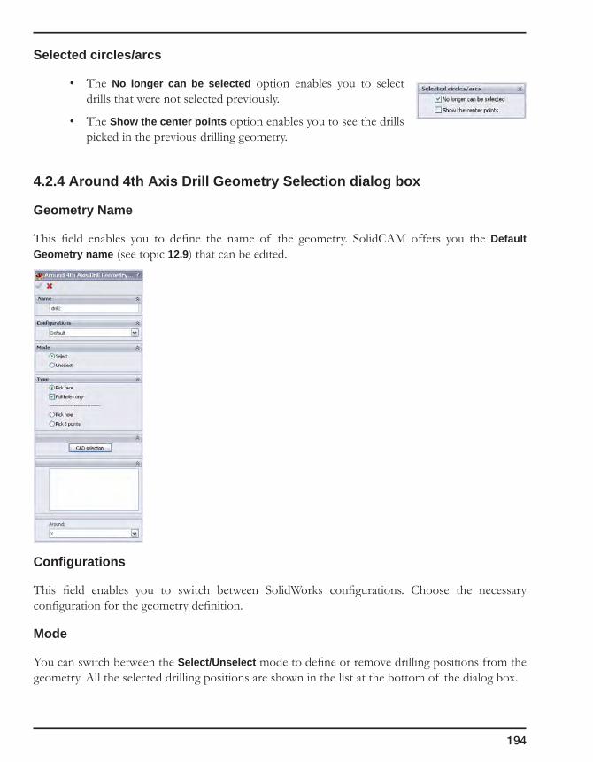
194
Selected circles/arcs
• The No longer can be selected option enables you to select drills that were not selected previously.
• The Show the center points option enables you to see the drills picked in the previous drilling geometry.
4.2.4 Around 4th Axis Drill Geometry Selection dialog box
Geometry Name
This field enables you to define the name of the geometry. SolidCAM offers you the Default Geometry name (see topic 12.9) that can be edited.
Configurations
This field enables you to switch between SolidWorks configurations. Choose the necessary configuration for the geometry definition.
Mode
You can switch between the Select/Unselect mode to define or remove drilling positions from the geometry. All the selected drilling positions are shown in the list at the bottom of the dialog box.
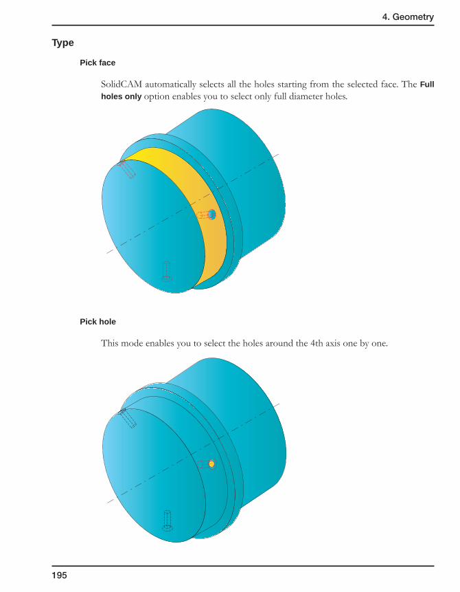
195
4. Geometry
Type
Pick face
SolidCAM automatically selects all the holes starting from the selected face. The Full holes only option enables you to select only full diameter holes.
Pick hole
This mode enables you to select the holes around the 4th axis one by one.
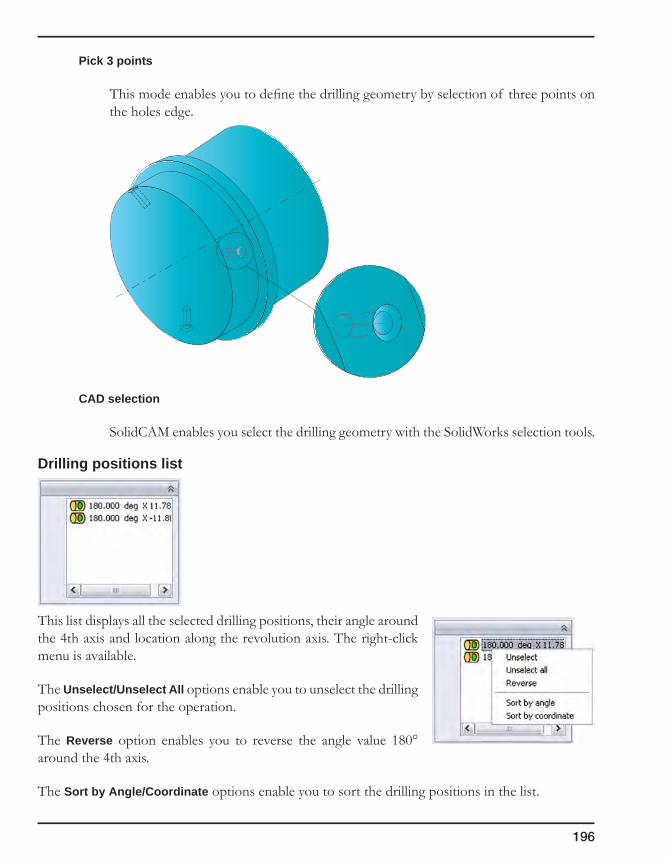
196
Pick 3 points
This mode enables you to define the drilling geometry by selection of three points on the holes edge.
CAD selection
SolidCAM enables you select the drilling geometry with the SolidWorks selection tools.
Drilling positions list
This list displays all the selected drilling positions, their angle around the 4th axis and location along the revolution axis. The right-click menu is available.
The Unselect/Unselect All options enable you to unselect the drilling positions chosen for the operation.
The Reverse option enables you to reverse the angle value 180° around the 4th axis.
The Sort by Angle/Coordinate options enable you to sort the drilling positions in the list.
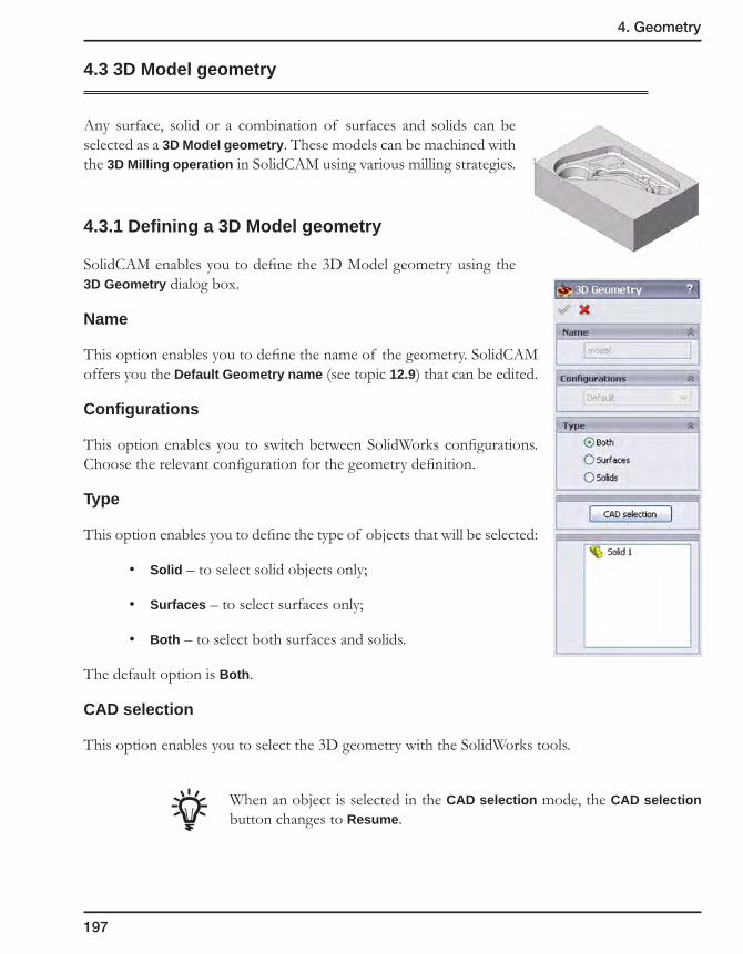
197
4. Geometry
4.3 3D Model geometry
Any surface, solid or a combination of surfaces and solids can be selected as a 3D Model geometry. These models can be machined with the 3D Milling operation in SolidCAM using various milling strategies.
4.3.1 Defining a 3D Model geometry
SolidCAM enables you to define the 3D Model geometry using the 3D Geometry dialog box.
Name
This option enables you to define the name of the geometry. SolidCAM offers you the Default Geometry name (see topic 12.9) that can be edited.
Configurations
This option enables you to switch between SolidWorks configurations. Choose the relevant configuration for the geometry definition.
Type
This option enables you to define the type of objects that will be selected:
• Solid – to select solid objects only;
• Surfaces – to select surfaces only;
• Both – to select both surfaces and solids.
The default option is Both.
CAD selection
This option enables you to select the 3D geometry with the SolidWorks tools.
When an object is selected in the CAD selection mode, the CAD selection button changes to Resume.
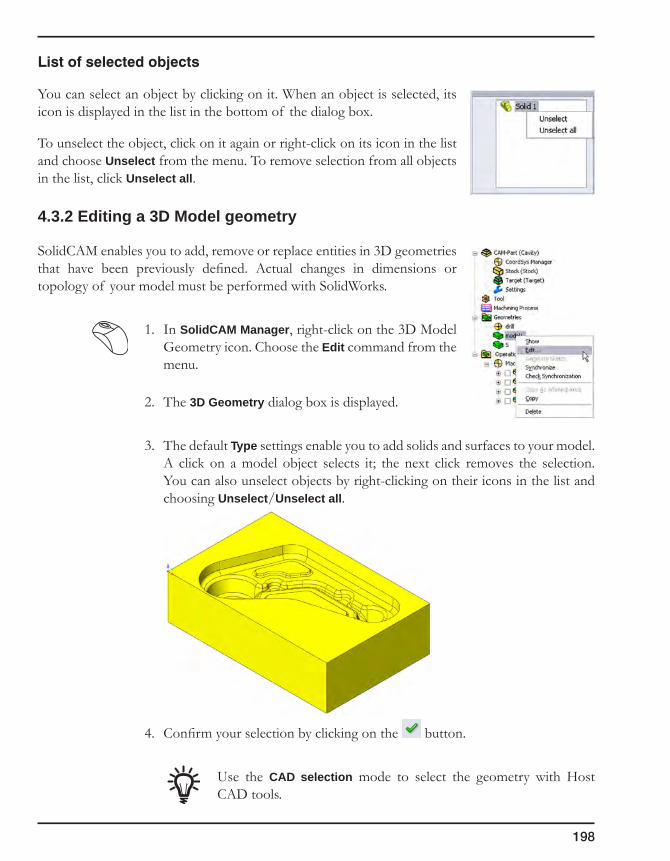
198
Listofselectedobjects
You can select an object by clicking on it. When an object is selected, its icon is displayed in the list in the bottom of the dialog box.
To unselect the object, click on it again or right-click on its icon in the list and choose Unselect from the menu. To remove selection from all objects in the list, click Unselect all.
4.3.2 Editing a 3D Model geometry
SolidCAM enables you to add, remove or replace entities in 3D geometries that have been previously defined. Actual changes in dimensions or topology of your model must be performed with SolidWorks.
1. In SolidCAM Manager, right-click on the 3D Model Geometry icon. Choose the Edit command from the menu.
2. The 3D Geometry dialog box is displayed.
3. The default Type settings enable you to add solids and surfaces to your model. A click on a model object selects it; the next click removes the selection. You can also unselect objects by right-clicking on their icons in the list and choosing Unselect/Unselect all.
4. Confirm your selection by clicking on the button.
Use the CAD selection mode to select the geometry with Host CAD tools.
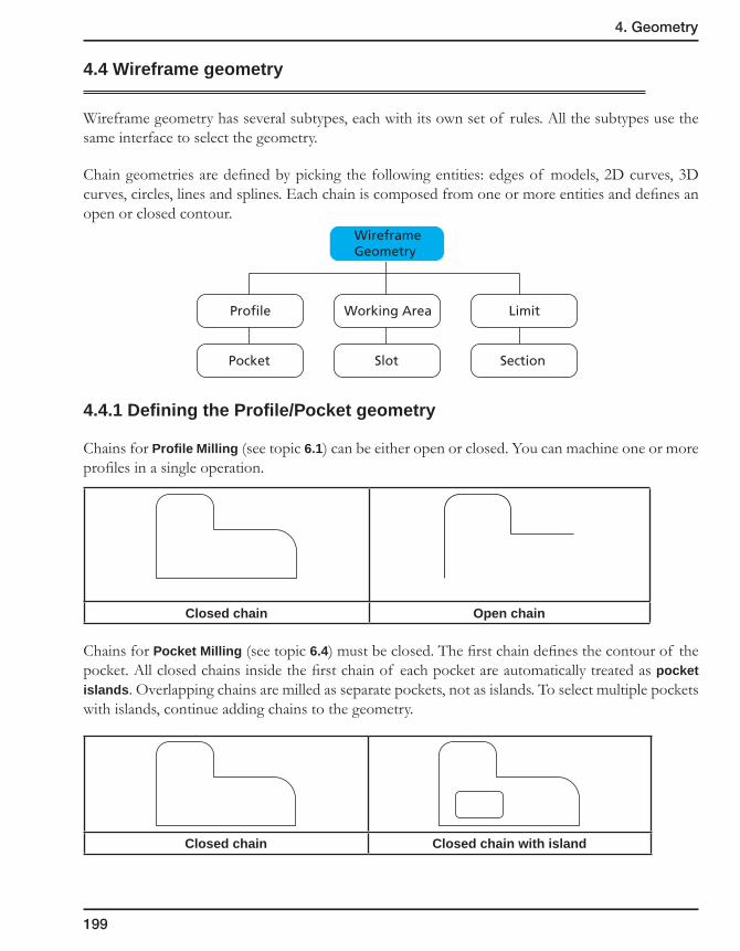
199
4. Geometry
4.4 Wireframe geometry
Wireframe geometry has several subtypes, each with its own set of rules. All the subtypes use the same interface to select the geometry.
Chain geometries are defined by picking the following entities: edges of models, 2D curves, 3D curves, circles, lines and splines. Each chain is composed from one or more entities and defines an open or closed contour.
4.4.1 Defining the Profile/Pocket geometry
Chains for Profile Milling (see topic 6.1) can be either open or closed. You can machine one or more profiles in a single operation.
Closed chain Open chain
Chains for Pocket Milling (see topic 6.4) must be closed. The first chain defines the contour of the pocket. All closed chains inside the first chain of each pocket are automatically treated as pocket islands. Overlapping chains are milled as separate pockets, not as islands. To select multiple pockets with islands, continue adding chains to the geometry.
Closed chain Closed chain with island
Section
Limit
WireframeGeometry
Slot
Working Area
Profile

200
1. Select a chain to define the geometry.
2. Confirm the chain definition with the Apply button.
3. When you have completed the geometry definition, confirm the Geometry Edit dialog box (see topic 4.5) with the button.
4.4.2 Defining the Working Area
Working areas are used in 3D Milling (see topic 7.1) to constrain the machining to certain areas of the 3D model. The working area is defined by a closed chain. The chain can consist either of selected points or of 2D/3D edges, curves or splines.
As in pocket geometries, working areas can be defined with internal chains, so that the islands are excluded from machining.
In this example, the working area has been selected to machine the cavity. The external chain defines the outside boundary of the area. The internal chain excludes the parting surface from machining.
1. Select a chain to define the geometry.
2. Confirm the chain definition with the button.
3. When you have completed the geometry definition, confirm the Geometry Edit dialog box (see topic 4.5) with the button.
4.4.3 Defining the Slot geometry
Chains for Slot Milling (see topic 6.9) can be either open or closed. You can machine one or more slots in one operation.
1. Click on the edges or lines that make up your slot.
2. Confirm the chain definition with the button.
3. When you have completed the geometry definition, confirm the Geometry Edit (see topic 4.5) dialog box with the button.
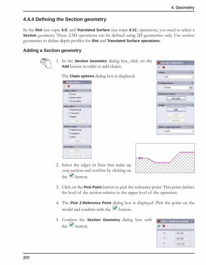
201
4. Geometry
4.4.4 Defining the Section geometry
In the Slot (see topic 6.9) and Translated Surface (see topic 6.11) operations, you need to select a Section geometry. These 2.5D operations can be defined using 2D geometries only. Use section geometries to define depth profiles for Slot and Translated Surface operations.
Adding a Section geometry
1. In the Section Geometry dialog box, click on the Add button in order to add chains.
The Chain options dialog box is displayed.
2. Select the edges or lines that make up your section and confirm by clicking on the button.
3. Click on the Pick Point button to pick the reference point. This point defines the level of the section relative to the upper level of the operation.
4. The Pick Z-Reference Point dialog box is displayed. Pick the point on the model and confirm with the button.
5. Confirm the Section Geometry dialog box with the button.

202
Editing a Section geometry
You can edit the section or redefine the reference point of the section.
1. In SolidCAM Manager, right-click on the Section geometry and choose Edit from the menu.
2. In the Section Geometry dialog box, click on the Pick Point button to pick the reference point again or on the Edit/Replace buttons to edit or replace the section chain using the Chain Selection dialog box.
3. Click on the button to confirm your changes and close the dialog box.
Spline Approximation
This field enables you to define the Spline approximation tolerance for the chain selection.
4.4.5 Defining the Limit geometry
A Translated Surface Operation (see topic 6.11) can be defined using 2D geometries only. With Limit geometries you can define boundaries for this operation.
1. Select a chain to define the geometry.
2. Confirm the chain definition with the button.
3. When you have completed the geometry definition, confirm the Geometry Edit
dialog box with the button.
LimitSection

203
4. Geometry
4.5 Editing chain geometries
To edit a chain, right-click on a geometry entry in SolidCAM Manager and choose Edit from the submenu.
The Geometry Edit dialog box is displayed.
4.5.1 Geometry Name
This option enables you to define the name of the geometry. SolidCAM offers you the Default Geometry name (see topic 12.9) that can be edited.
4.5.2 Configurations
This option enables you to switch between SolidWorks configurations. Choose the relevant configuration for the geometry definition.
4.5.3 Adding a Chain
You can add a chain to the existing set of chains in the current geometry. The new chain is added under the next sequential number.
1. Select the chain geometry using the Single entities (see topic 4.5.6) and Automatic selection options (see topic 4.5.7).
2. Confirm the chain definition with the button.
or
Use the Add Multi-chain button to automatically define a number of chains (see topic 4.6).
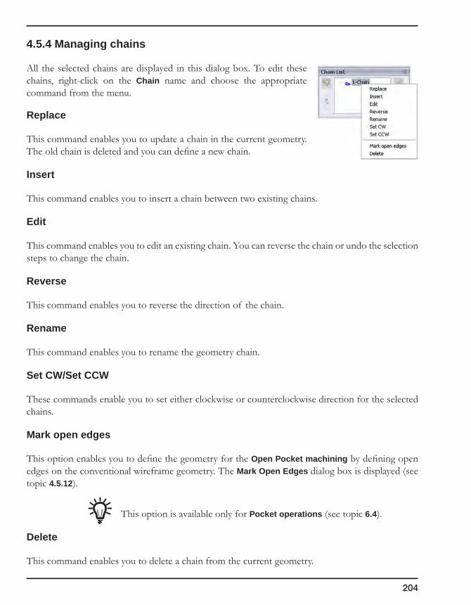
204
4.5.4 Managing chains
All the selected chains are displayed in this dialog box. To edit these chains, right-click on the Chain name and choose the appropriate command from the menu.
Replace
This command enables you to update a chain in the current geometry. The old chain is deleted and you can define a new chain.
Insert
This command enables you to insert a chain between two existing chains.
Edit
This command enables you to edit an existing chain. You can reverse the chain or undo the selection steps to change the chain.
Reverse
This command enables you to reverse the direction of the chain.
Rename
This command enables you to rename the geometry chain.
Set CW/Set CCW
These commands enable you to set either clockwise or counterclockwise direction for the selected chains.
Mark open edges
This option enables you to define the geometry for the Open Pocket machining by defining open edges on the conventional wireframe geometry. The Mark Open Edges dialog box is displayed (see topic 4.5.12).
This option is available only for Pocket operations (see topic 6.4).
Delete
This command enables you to delete a chain from the current geometry.
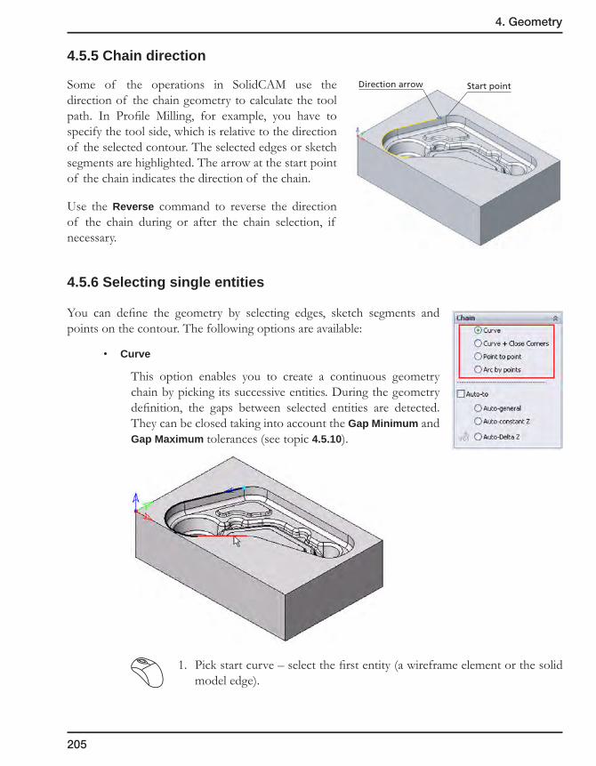
205
4. Geometry
4.5.5 Chain direction
Some of the operations in SolidCAM use the direction of the chain geometry to calculate the tool path. In Profile Milling, for example, you have to specify the tool side, which is relative to the direction of the selected contour. The selected edges or sketch segments are highlighted. The arrow at the start point of the chain indicates the direction of the chain.
Use the Reverse command to reverse the direction of the chain during or after the chain selection, if necessary.
4.5.6 Selecting single entities
You can define the geometry by selecting edges, sketch segments and points on the contour. The following options are available:
• Curve
This option enables you to create a continuous geometry chain by picking its successive entities. During the geometry definition, the gaps between selected entities are detected. They can be closed taking into account the Gap Minimum and Gap Maximum tolerances (see topic 4.5.10).
1. Pick start curve – select the first entity (a wireframe element or the solid model edge).
Start pointDirection arrow

206
2. Pick next curve – select the next curve that belongs to the chain. If the detected gap is smaller than the Gap Minimum tolerance, it is being closed automatically by extending/shortening chosen entities up to their virtual intersection point. If the gap is greater than the Gap Minimum tolerance but smaller than the Gap Maximum tolerance, a message is displayed asking you if you want to close the gap. If you confirm the message, the gap is being closed automatically by extending/shortening chosen entities up to their virtual intersection point. If you cancel, the gap is not being closed, and the last entity is being unselected. In case the gap is larger than the Gap Maximum tolerance, the selected entity is not accepted, and the following message is displayed:
3. To complete the selection, click on the button.
Associativity
SolidCAM keeps the associativity to any edge or sketch entity. Any change made to the model or sketch automatically updates the selected geometry.
• Curve + Close corners
This option enables you to close the gaps between successive chain entities irrespective of the Gap Minimum and Gap Maximum values by virtually extending the entities up to their intersection.
Splines and arcs are extended by lines tangential to the arc/spline at its end point.
1. Pick start curve – select the first entity (a wireframe element or the solid model edge).
First selected entity
Next selected entity

207
4. Geometry
2. Pick next curve – select the next curve that belongs to the chain. When a gap is detected between these entities, the chain is continued by virtually extending the selected entities, according to the direction of the first entity, up to the virtual intersection point. If an intersection point cannot be found by extending either one or both selected entities, the following message is displayed:
In case several possible intersection points exist, the point closest to the last vertex of the first selected entity is chosen.
3. To complete the selection, click on the button.
Associativity
When the model used for the geometry definition is modified, SolidCAM enables you to synchronize the geometry with the updated model. During the synchronization SolidCAM determines gaps areas created using the Curve + Close Corners option and regenerates the extension of the chain elements so as to close the gaps.
• Point to point
This option enables you to connect the specified points with a straight line.
1. Pick start point – pick a point on the model or enter the coordinates into the command line.
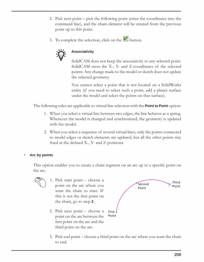
208
2. Pick next point – pick the following point (enter the coordinates into the command line), and the chain element will be created from the previous point up to this point.
3. To complete the selection, click on the button.
Associativity
SolidCAM does not keep the associativity to any selected point. SolidCAM saves the X-, Y- and Z-coordinates of the selected points. Any change made to the model or sketch does not update the selected geometry.
You cannot select a point that is not located on a SolidWorks entity (if you need to select such a point, add a planer surface under the model and select the points on that surface).
The following rules are applicable to virtual line selection with the Point to Point option:
1. When you select a virtual line between two edges, the line behaves as a spring. Whenever the model is changed and synchronized, the geometry is updated with the model.
2. When you select a sequence of several virtual lines, only the points connected to model edges or sketch elements are updated, but all the other points stay fixed at the defined X-, Y- and Z-positions.
• Arc by points
This option enables you to create a chain segment on an arc up to a specific point on the arc.
1. Pick start point – choose a point on the arc where you want the chain to start. If this is not the first point on the chain, go to step 2.
2. Pick next point – choose a point on the arc between the first point on the arc and the third point on the arc.
3. Pick end point – choose a third point on the arc where you want the chain to end.
First Point
Second Point
Third Point

209
4. Geometry
Associativity
SolidCAM does not keep the associativity to any selected arcs by points. SolidCAM saves the X,- Y- and Z-coordinates of the selected points. Any change made to the model or sketch does not update the selected geometry.
4.5.7 Automatic selection
SolidCAM automatically determines the chain entities and closes the chain contour. The following options are available:
Auto-to
The chain is selected by specifying the start curve, the direction of the chain and the element up to which the chain is created. SolidCAM enables you to choose any model edge, vertex or sketch entity to determine the chain end.
When the end item is chosen, SolidCAM determines the chain according to the rules of the chosen selection mode (Auto-general, Auto-Constant Z or Auto-Delta Z). The chain selection is terminated when the selected end item is reached.
If the chosen end item cannot be reached by the chain flow, the chain definition is terminated when the start chain segment is reached. The chain is automatically closed.
Start entity Selected chain
End entity
Start entity Selected chain
End entity

210
The confirmation message is displayed.
The Auto-to option is useful if you do not want to define a closed chain, but an open chain up to a certain element.
• Auto-general
SolidCAM highlights all entities connected to the last chain entity. You have to select the entity along which you want the chain to continue.
• Auto-constantZ
This option identifies only entities on the same XY-plane with the previously selected chain entity. You are only prompted to identify the next chain element when two entities on the same Z-level are connected to the chain. The system tolerance for this option can be set in the SolidCAM Settings.
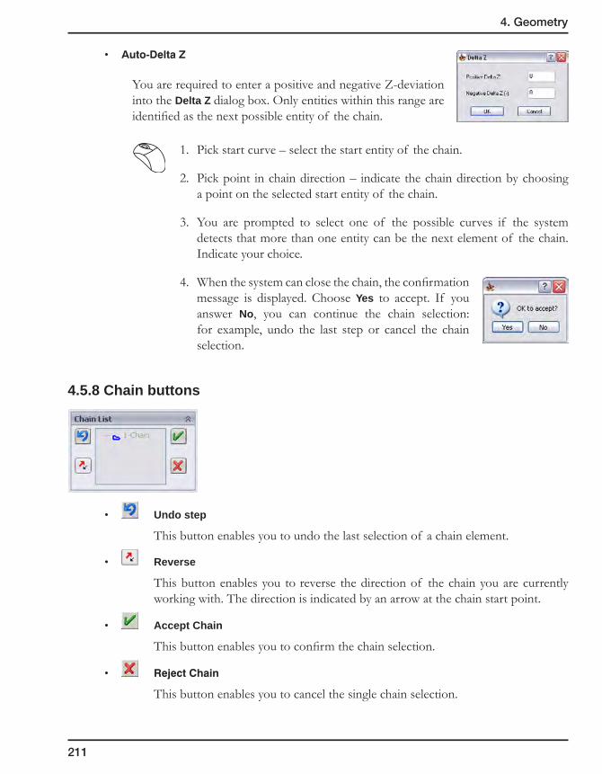
211
4. Geometry
• Auto-DeltaZ
You are required to enter a positive and negative Z-deviation into the Delta Z dialog box. Only entities within this range are identified as the next possible entity of the chain.
1. Pick start curve – select the start entity of the chain.
2. Pick point in chain direction – indicate the chain direction by choosing a point on the selected start entity of the chain.
3. You are prompted to select one of the possible curves if the system detects that more than one entity can be the next element of the chain. Indicate your choice.
4. When the system can close the chain, the confirmation message is displayed. Choose Yes to accept. If you answer No, you can continue the chain selection: for example, undo the last step or cancel the chain selection.
4.5.8 Chain buttons
• Undo step
This button enables you to undo the last selection of a chain element.
• Reverse
This button enables you to reverse the direction of the chain you are currently working with. The direction is indicated by an arrow at the chain start point.
• Accept Chain
This button enables you to confirm the chain selection.
• RejectChain
This button enables you to cancel the single chain selection.

212
4.5.9 Options
Spline approximation
This field enables you to define the Spline approximation tolerance for the chain selection. Arcs on the XY-plane are saved as arcs in the SolidCAM database; if you select an arc or spline that is not on the XY-plane of the actual part Coordinate System, SolidCAM will do the following:
1. Project the arc or spline on the XY-plane of the active CoordSys and divide it into segments according to the specified tolerance.
2. In order to reduce the number of segments, SolidCAM tries to fit arcs on the segments generated in step 1 according to the specified tolerance multiplied by 3.
4.5.10 Gap control
This field enables you to change the gap tolerances for the current geometry during the geometry definition.
The automatic selection function for chain geometries uses certain tolerances to decide whether two consequent elements are connected or not. The behavior of this function depends on the gap between the entities. The Gap minimum and Gap maximum parameters define the range of gap tolerance values used for the chain geometry definition.
The default values of these parameters are inherited from the SolidCAM Settings (see topic 12.4.3). In the Geometry Edit dialog box, you can edit the tolerance values during any stage of any chain definition (for example, at start of chain definition or during the chain definition). During the geometry chains definition, SolidCAM uses these parameters in order to decide whether to connect two successive chain entities, if a gap between them is detected.
Tolerance
Tolerance
Spline
Arc

213
4. Geometry
• If the gap between the edges is smaller than the specified Gap minimum value, the system automatically continues the chain and closes the gap with a line.
• If the gap is in the range between the Gap minimum and Gap maximum values, you are asked whether the gap should be closed.
If you answer Yes, the gap is automatically closed with a line.
• If the gap is larger than the Gap maximum value, the following message is displayed:
When the message is confirmed, the last selected chain entity is rejected.
4.5.11 Add Multi-Chain
SolidCAM enables you to define a number of chains on the model by selecting its elements. The program automatically creates chains from the selected elements.
For more information on Multi-chain selection, see topic 4.6.
4.5.12 Mark Open Edges dialog box
This dialog box enables you to mark the open edges on already selected pocket chains by picking them.
Pocket geometry
Open edge
Open pocket
Closed edges

214
Mark as
This section offers you the following selection modes:
• Open
When this option is chosen, picking a pocket geometry edge marks it as open.
• Wall
When this option is chosen, picking a pocket geometry edge marks it as closed (wall).
• Toggle
When this option is chosen, picking a closed edge marks it as open and the next picking marks it as closed, and so on.
Select
This section offers you the following selection methods:
• Singleentity
When this method is chosen, you can pick single entities in order to mark them as open/closed.
• From/Toentities
When this method is chosen, you can mark a segment of the pocket geometry by picking the start and the end entities.
CAD Selection
This button enables you to perform the selection using the CAD tools.
The marking of open edges is available only for Pocket operations (see topic 6.4).

215
4. Geometry
4.6 Chains Selection dialog box
The Chains Selection dialog box enables you to define a number of chains on the model by selecting its elements. The system automatically creates chains from the selected elements.
Mode
• Select – this mode enables you to select the elements to define the chains.
• Unselect – this mode enables you to unselect the previously selected elements.
Type
• Edges
SolidCAM enables you to choose model edges to build a chain geometry.
• Text
SolidCAM enables you to choose text to build a chain geometry.
• Faces
When this mode is chosen, SolidCAM enables you to pick a model face. All the loops of this face are collected and closed geometry chains are created. The Loops filter is applied to the collected loops to exclude all those that do not match the specified criteria.
Selection Filter
When this check box is selected, you can select only elements located on a specific Z-level. To define the Z-level, either enter the value in the dialog box or click on the On Z-Level button and pick the level on the model.
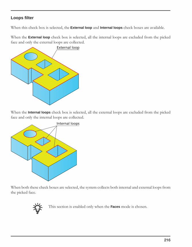
216
Loops filter
When this check box is selected, the External loop and Internal loops check boxes are available.
When the External loop check box is selected, all the internal loops are excluded from the picked face and only the external loops are collected.
When the Internal loops check box is selected, all the external loops are excluded from the picked face and only the internal loops are collected.
When both these check boxes are selected, the system collects both internal and external loops from the picked face.
This section is enabled only when the Faces mode is chosen.
External loop
Internal loops

217
4. Geometry
CAD selection
Click on this button to select the chains with the Host CAD tools.
Get All
This button enables you to select all of the model elements.
Sort Type
When there is more than one chain, this option enables you to determine the chain you would like to start from. The Sort chains dialog box is displayed (see topic 4.6.2).
Chains direction
This option enables you to determine the cutting direction of each chain. The Chains Direction dialog box is displayed (see topic 4.6.1).
View Chains
This option enables you to see the chains before they are created.
4.6.1 Chains Direction dialog box
The Chains Direction dialog box enables you to determine the direction of the chain.
Closed chains direction
This option enables you to determine the direction of closed chains.
• Externalchainsdirection
External chains are the outer borders of a pocket. You can determine if you want the chain to go clockwise or counterclockwise by choosing CCW or CW.
• Internalchainsopposite
Internal chains are located within the boundaries of external chains. Selecting this check box, you can have the internal chains go in the direction opposite to that of the external chains.

218
Open chains direction
This option enables you to determine the direction of open chains.
• To center: the chain start point is the end of the chain furthest from the given center point.
• From center: the chain start point is the end of the chain closest to the given center point.
Selecting the Change center position check box enables you to choose the center position by entering the X- and Y-values or by picking a point on the model.
If you do not change the center position, the CoordSys origin is used as center point.
4.6.2 Chain sorting
The Chain sorting option enables you to define the order in which you want the chains to be created.
Sort by Distance
The chain closest to the last chain is chosen using two options:
• EndtoStart
The next chain is the chain with the start point closest to the end point of the last chain.
• StarttoStart
The next chain is the chain with the start point closest to the start point of the last chain.
Sort by Value
The next chain that is closest to the last chain in a given direction is chosen.
• Xstart
The next chain is the one in the X-direction.
• Ystart
The next chain is the one in the Y-direction.
219
4. Geometry
• Reverse
The direction of the chains changes (X-start: Left to Right; Y-start: Upward or Downward).
Polar Sort
Chains are selected around a specific point. If no point is chosen, the default point is the CoordSys origin of the CAM-Part.
• CWDirection
The order of the chains is in clockwise direction around the point.
• CCWDirection
The order of the chains is in counterclockwise direction around the point.
• Changecenterposition
The center position is chosen either by entering X-/Y-values or by picking a point on the model.
• Startangle
This field controls the angle between the start point of the chain and the point of rotation.
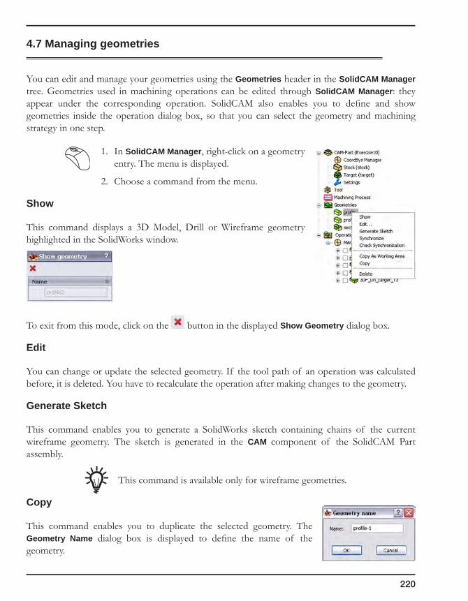
220
4.7 Managing geometries
You can edit and manage your geometries using the Geometries header in the SolidCAM Manager tree. Geometries used in machining operations can be edited through SolidCAM Manager: they appear under the corresponding operation. SolidCAM also enables you to define and show geometries inside the operation dialog box, so that you can select the geometry and machining strategy in one step.
1. In SolidCAM Manager, right-click on a geometry entry. The menu is displayed.
2. Choose a command from the menu.
Show
This command displays a 3D Model, Drill or Wireframe geometry highlighted in the SolidWorks window.
To exit from this mode, click on the button in the displayed Show Geometry dialog box.
Edit
You can change or update the selected geometry. If the tool path of an operation was calculated before, it is deleted. You have to recalculate the operation after making changes to the geometry.
Generate Sketch
This command enables you to generate a SolidWorks sketch containing chains of the current wireframe geometry. The sketch is generated in the CAM component of the SolidCAM Part assembly.
This command is available only for wireframe geometries.
Copy
This command enables you to duplicate the selected geometry. The Geometry Name dialog box is displayed to define the name of the geometry.

221
4. Geometry
Copy as Working area
This command copies the selected geometry as a working area.
SolidCAM generates a SolidWorks sketch containing chains of the selected geometry. The sketch will be generated in the CAM component of the SolidCAM Part assembly. A new Working area geometry is defined using this sketch.
The Geometry Name dialog box enables you to define the name of the geometry.
Delete/Delete All
You can delete geometries not used in any machining operation. These geometries are displayed under the Geometries header. Any geometry used in operations appears under the respective operations only and cannot be deleted unless the operation is deleted as well.
The Delete all command is only available when you right-click on the Geometries header. It deletes all geometries not currently used in any machining operation. Whenever you click on a single geometry, the Delete command is available for the selected geometry only.
Synchronize/Check synchronization
When the SolidWorks model is updated, you can check the compliance of the SolidCAM geometry to the updated SolidWorks model. If the SolidCAM geometry is not synchronized with the SolidWorks model, you can synchronize it.
4.7.1 Synchronization of the Wireframe geometry
SolidCAM Wireframe geometry is based on the SolidWorks model elements such as edges, vertices or sketches.
When the SolidWorks model is changed, SolidCAM uses the synchronization algorithm to synchronize the geometry with the updated SolidWorks model.
SolidCAM Geometrybased on the
SolidWorks Model
SolidWorks Model
SolidCAM Geometryis updated
SolidWorks Model has changed,SolidCAM Geometry has to
be updated
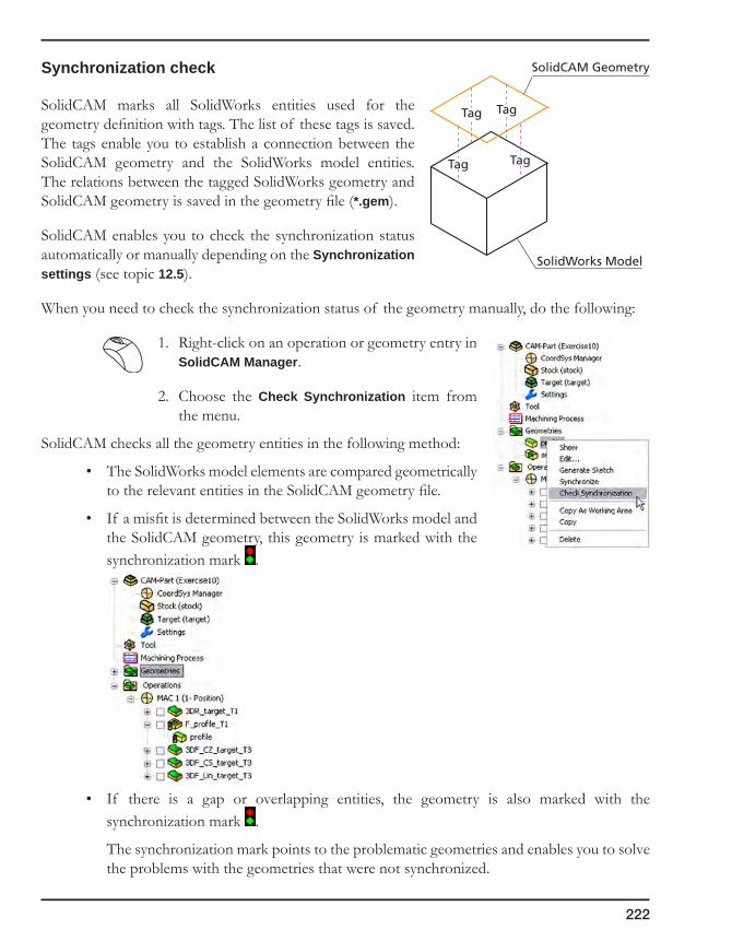
222
Synchronization check
SolidCAM marks all SolidWorks entities used for the geometry definition with tags. The list of these tags is saved. The tags enable you to establish a connection between the SolidCAM geometry and the SolidWorks model entities. The relations between the tagged SolidWorks geometry and SolidCAM geometry is saved in the geometry file (*.gem).
SolidCAM enables you to check the synchronization status automatically or manually depending on the Synchronization settings (see topic 12.5).
When you need to check the synchronization status of the geometry manually, do the following:
1. Right-click on an operation or geometry entry in SolidCAM Manager.
2. Choose the Check Synchronization item from the menu.
SolidCAM checks all the geometry entities in the following method:
• The SolidWorks model elements are compared geometrically to the relevant entities in the SolidCAM geometry file.
• If a misfit is determined between the SolidWorks model and the SolidCAM geometry, this geometry is marked with the synchronization mark .
• If there is a gap or overlapping entities, the geometry is also marked with the synchronization mark .
The synchronization mark points to the problematic geometries and enables you to solve the problems with the geometries that were not synchronized.
SolidCAM Geometry
TagTag
Tag Tag
SolidWorks Model
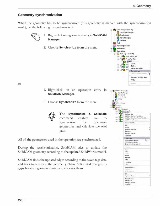
223
4. Geometry
Geometry synchronization
When the geometry has to be synchronized (this geometry is marked with the synchronization mark), do the following to synchronize it:
1. Right-click on a geometry entry in SolidCAM Manager.
2. Choose Synchronize from the menu.
or
1. Right-click on an operation entry in SolidCAM Manager.
2. Choose Synchronize from the menu.
The Synchronize & Calculate command enables you to synchronize the operation geometries and calculate the tool path.
All of the geometries used in the operation are synchronized.
During the synchronization, SolidCAM tries to update the SolidCAM geometry according to the updated SolidWorks model.
SolidCAM finds the updated edges according to the saved tags data and tries to re-create the geometry chain. SolidCAM recognizes gaps between geometry entities and closes them.
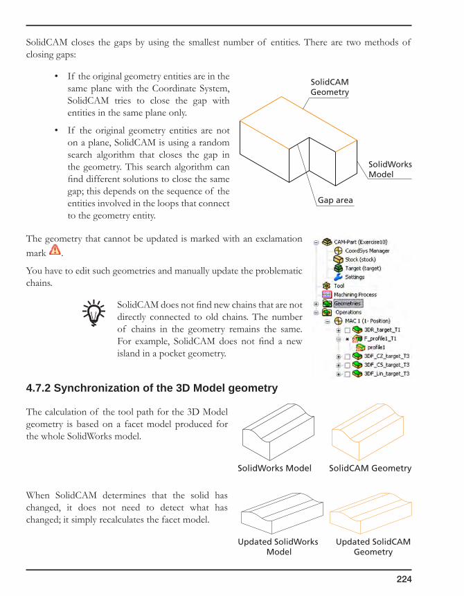
224
SolidCAM closes the gaps by using the smallest number of entities. There are two methods of closing gaps:
• If the original geometry entities are in the same plane with the Coordinate System, SolidCAM tries to close the gap with entities in the same plane only.
• If the original geometry entities are not on a plane, SolidCAM is using a random search algorithm that closes the gap in the geometry. This search algorithm can find different solutions to close the same gap; this depends on the sequence of the entities involved in the loops that connect to the geometry entity.
The geometry that cannot be updated is marked with an exclamation mark .
You have to edit such geometries and manually update the problematic chains.
SolidCAM does not find new chains that are not directly connected to old chains. The number of chains in the geometry remains the same. For example, SolidCAM does not find a new island in a pocket geometry.
4.7.2 Synchronization of the 3D Model geometry
The calculation of the tool path for the 3D Model geometry is based on a facet model produced for the whole SolidWorks model.
When SolidCAM determines that the solid has changed, it does not need to detect what has changed; it simply recalculates the facet model.
SolidCAMGeometry
SolidWorksModel
Gap area
SolidCAM GeometrySolidWorks Model
Updated SolidCAMGeometry
Updated SolidWorks Model
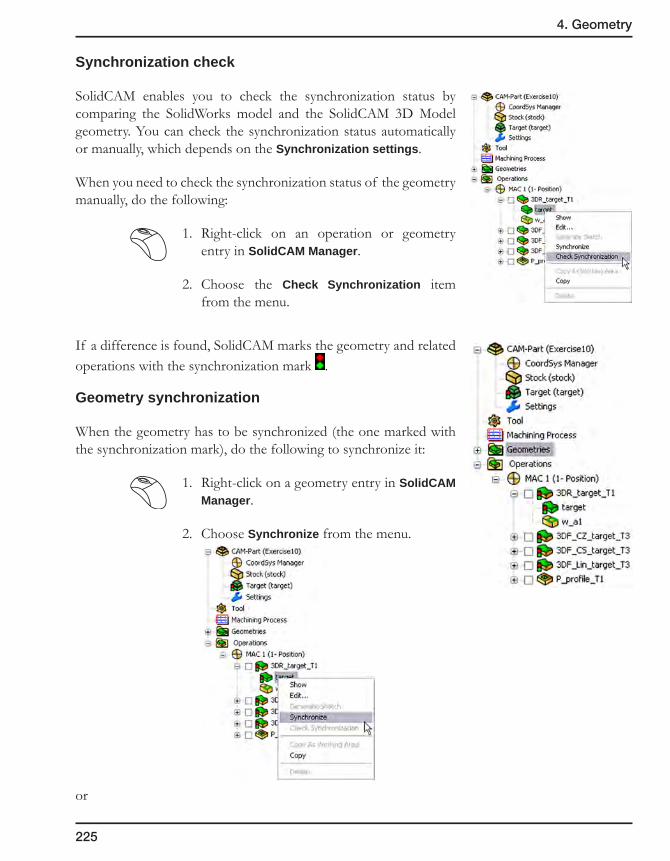
225
4. Geometry
Synchronization check
SolidCAM enables you to check the synchronization status by comparing the SolidWorks model and the SolidCAM 3D Model geometry. You can check the synchronization status automatically or manually, which depends on the Synchronization settings.
When you need to check the synchronization status of the geometry manually, do the following:
1. Right-click on an operation or geometry entry in SolidCAM Manager.
2. Choose the Check Synchronization item from the menu.
If a difference is found, SolidCAM marks the geometry and related operations with the synchronization mark .
Geometry synchronization
When the geometry has to be synchronized (the one marked with the synchronization mark), do the following to synchronize it:
1. Right-click on a geometry entry in SolidCAM Manager.
2. Choose Synchronize from the menu.
or
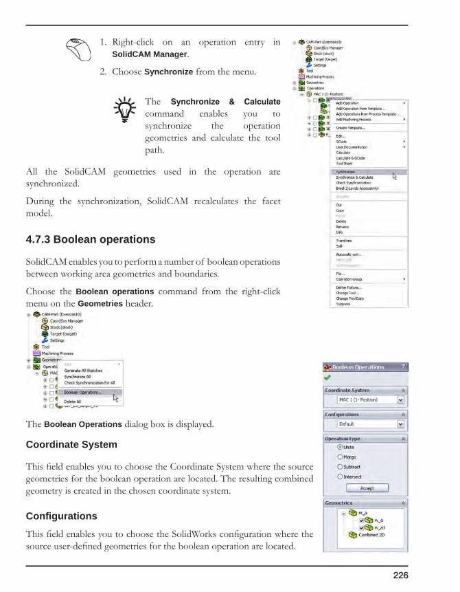
226
1. Right-click on an operation entry in SolidCAM Manager.
2. Choose Synchronize from the menu.
The Synchronize & Calculate command enables you to synchronize the operation geometries and calculate the tool path.
All the SolidCAM geometries used in the operation are synchronized.
During the synchronization, SolidCAM recalculates the facet model.
4.7.3 Boolean operations
SolidCAM enables you to perform a number of boolean operations between working area geometries and boundaries.
Choose the Boolean operations command from the right-click menu on the Geometries header.
The Boolean Operations dialog box is displayed.
Coordinate System
This field enables you to choose the Coordinate System where the source geometries for the boolean operation are located. The resulting combined geometry is created in the chosen coordinate system.
Configurations
This field enables you to choose the SolidWorks configuration where the source user-defined geometries for the boolean operation are located.

227
4. Geometry
Operation type
This field enables you to define the type of the boolean operation. The following boolean operations are available:
Unite
This option enables you to unite selected geometries into a single one. All internal segments are removed; the resulting geometry is outer profile.
Merge
This option enables you to merge a number of geometries, created by different methods, into a single one.
Subtract
This option enables you to perform subtraction of two geometries. The order of the geometry selection is important; the second selected geometry is subtracted from the first selected one.
Geometry 1 Geometry 2
Geometry 3
Sourcegeometries
Resultinggeometry
Geometry 1 Geometry 2
Sourcegeometries
Resultinggeometry
Geometry 1 Geometry 2
Source geometries
Resulting geometry
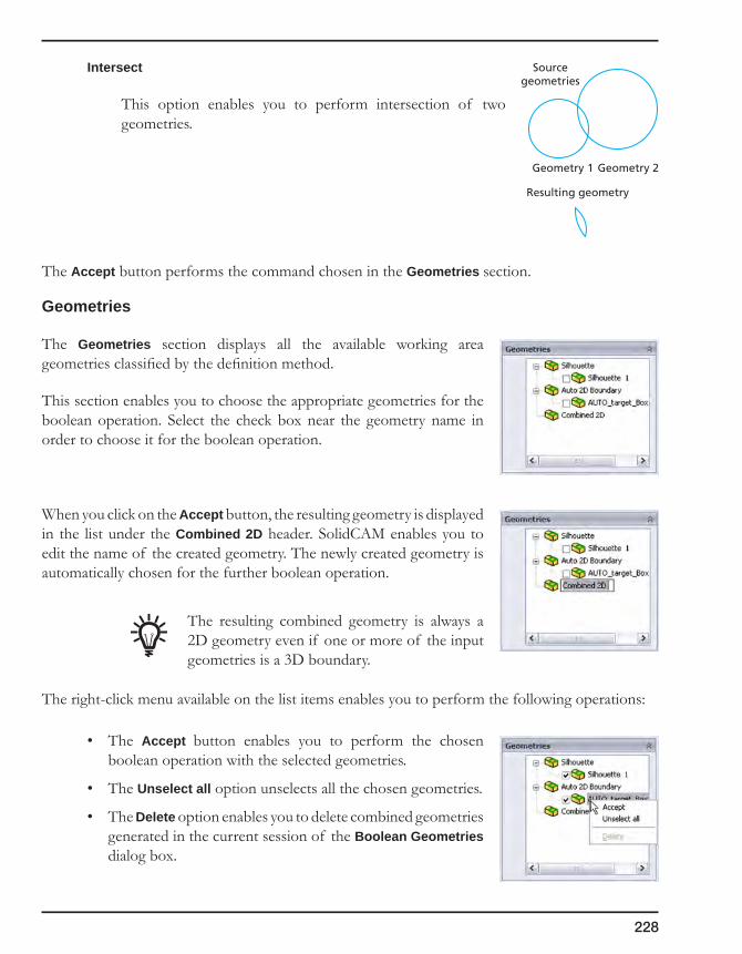
228
Intersect
This option enables you to perform intersection of two geometries.
The Accept button performs the command chosen in the Geometries section.
Geometries
The Geometries section displays all the available working area geometries classified by the definition method.
This section enables you to choose the appropriate geometries for the boolean operation. Select the check box near the geometry name in order to choose it for the boolean operation.
When you click on the Accept button, the resulting geometry is displayed in the list under the Combined 2D header. SolidCAM enables you to edit the name of the created geometry. The newly created geometry is automatically chosen for the further boolean operation.
The resulting combined geometry is always a 2D geometry even if one or more of the input geometries is a 3D boundary.
The right-click menu available on the list items enables you to perform the following operations:
• The Accept button enables you to perform the chosen boolean operation with the selected geometries.
• The Unselect all option unselects all the chosen geometries.
• The Delete option enables you to delete combined geometries generated in the current session of the Boolean Geometries dialog box.
Geometry 1 Geometry 2
Sourcegeometries
Resulting geometry

OperationsIn SolidCAM, an operation is a single machining step. A workpiece is usually manufactured using several machining steps and technologies. For each of these steps you can define a separate operation.
An operation can be very complex, but always uses one tool, one major geometry and executes one machining type, e.g. 3D Milling, Profile Milling or Drilling. You can edit any single machining operation, change the operation sequence and generate the GCode, combine and split the operation list of your CAM-Part.
Adding an operation
Operation dialog box interface
Working with operations
Operation Transformations
Fixture
5

230
5.1 Adding an operation
This command enables you to add a new operation to your CAM-Part. In SolidCAM, an operation is a single machining step. Normally, you manufacture a workpiece using several machining steps and technologies. For each of these steps you can define a separate operation. An operation can be very complex, but always uses one tool, one major geometry and executes one machining type, e.g. 3D milling, profile milling or drilling.
You can edit any single machining operation, change the operation sequence and generate the GCode, combine and split the operation list of your CAM-Part.
1. In SolidCAM Manager, right-click on an operation.
2. Move to the Add Operation submenu and choose the type of operation you want to define.
• When you add an operation by right-clicking on the Operations header, the new operation is added at the end of the operation list.
• When you add an operation by right-clicking on an existing operation, the new operation is inserted after the selected operation.
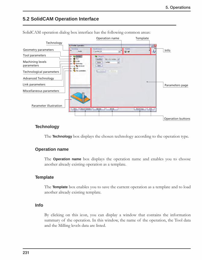
231
5. Operations
5.2 SolidCAM Operation Interface
SolidCAM operation dialog box interface has the following common areas:
Technology
The Technology box displays the chosen technology according to the operation type.
Operation name
The Operation name box displays the operation name and enables you to choose another already existing operation as a template.
Template
The Template box enables you to save the current operation as a template and to load another already existing template.
Info
By clicking on this icon, you can display a window that contains the information summary of the operation. In this window, the name of the operation, the Tool data and the Milling levels data are listed.
Technology
Geometry parameters
Parameter illustration
Parameters page
Info
Tool parameters
Machining levelsparameters
Link parameters
Operation name
Operation buttons
Template
Technological parameters
Miscellaneous parameters
Advanced Technology

232
Parameters pages and illustration
The list on the left side of the dialog box enables you to switch between the following parameters pages:
• Geometry
This page enables you to define the geometry for the operation.
• Tool
This page enables you to define the tool for the operation.
• Levels
This page enables you to define the machining levels for the operation.
• Technology
This page enables you to define the technological parameters such as offsets, roughing and finishing data, depth type, etc.
The Advanced Technology page contains the infrequently used parameters and options whose definition is required only in particular machining cases.
• Link
This page enables you to define the way how the tool approaches the material and retreats away.
• Misc.parameters
This page contains the miscellaneous parameters such as Message, Extra parameters, and so forth.
In the bottom left corner of the dialog box, the illustration of a currently selected interface element is displayed to facilitate the definition of the corresponding parameter.
Operation buttons
At the bottom, the operation buttons are located. These buttons enable you to save and calculate the operation, start its simulation, etc.
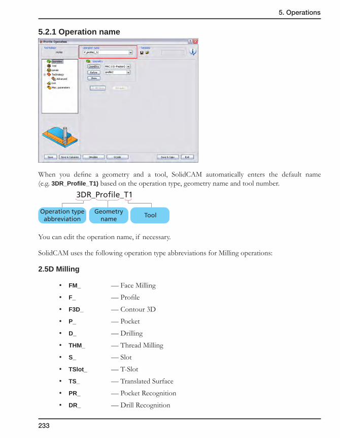
233
5. Operations
5.2.1 Operation name
When you define a geometry and a tool, SolidCAM automatically enters the default name (e.g. 3DR_Profile_T1) based on the operation type, geometry name and tool number.
You can edit the operation name, if necessary.
SolidCAM uses the following operation type abbreviations for Milling operations:
2.5D Milling
• FM_ — Face Milling
• F_ — Profile
• F3D_ — Contour 3D
• P_ — Pocket
• D_ — Drilling
• THM_ — Thread Milling
• S_ — Slot
• TSlot_ — T-Slot
• TS_ — Translated Surface
• PR_ — Pocket Recognition
• DR_ — Drill Recognition
3DR_Profile_T1
ToolGeometry
nameOperation type
abbreviation
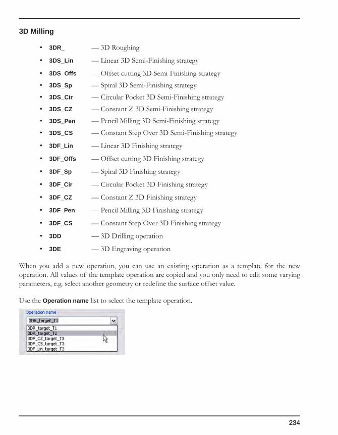
234
3D Milling
• 3DR_ — 3D Roughing
• 3DS_Lin — Linear 3D Semi-Finishing strategy
• 3DS_Offs — Offset cutting 3D Semi-Finishing strategy
• 3DS_Sp — Spiral 3D Semi-Finishing strategy
• 3DS_Cir — Circular Pocket 3D Semi-Finishing strategy
• 3DS_CZ — Constant Z 3D Semi-Finishing strategy
• 3DS_Pen — Pencil Milling 3D Semi-Finishing strategy
• 3DS_CS — Constant Step Over 3D Semi-Finishing strategy
• 3DF_Lin — Linear 3D Finishing strategy
• 3DF_Offs — Offset cutting 3D Finishing strategy
• 3DF_Sp — Spiral 3D Finishing strategy
• 3DF_Cir — Circular Pocket 3D Finishing strategy
• 3DF_CZ — Constant Z 3D Finishing strategy
• 3DF_Pen — Pencil Milling 3D Finishing strategy
• 3DF_CS — Constant Step Over 3D Finishing strategy
• 3DD — 3D Drilling operation
• 3DE — 3D Engraving operation
When you add a new operation, you can use an existing operation as a template for the new operation. All values of the template operation are copied and you only need to edit some varying parameters, e.g. select another geometry or redefine the surface offset value.
Use the Operation name list to select the template operation.
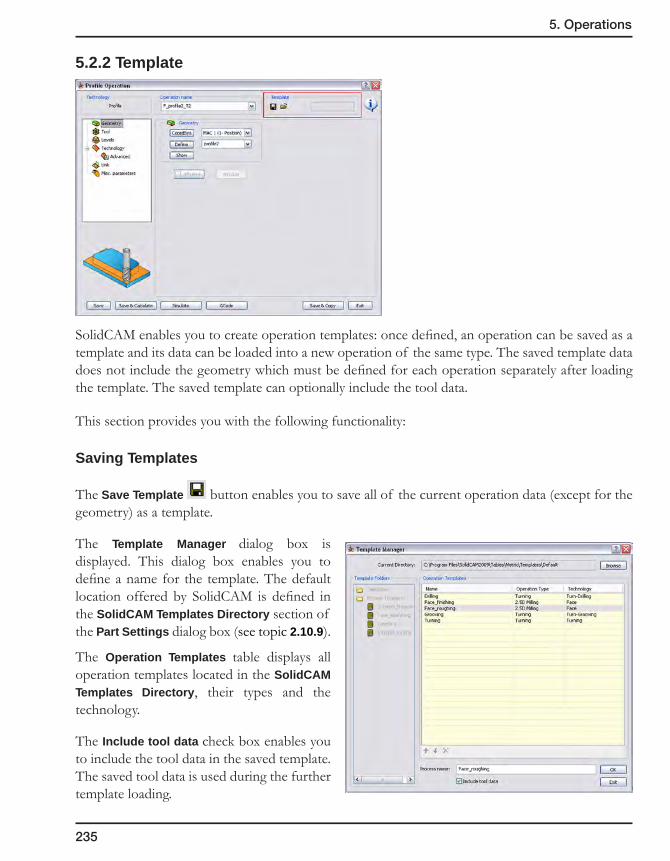
235
5. Operations
5.2.2 Template
SolidCAM enables you to create operation templates: once defined, an operation can be saved as a template and its data can be loaded into a new operation of the same type. The saved template data does not include the geometry which must be defined for each operation separately after loading the template. The saved template can optionally include the tool data.
This section provides you with the following functionality:
Saving Templates
The Save Template button enables you to save all of the current operation data (except for the geometry) as a template.
The Template Manager dialog box is displayed. This dialog box enables you to define a name for the template. The default location offered by SolidCAM is defined in the SolidCAM Templates Directory section of the Part Settings dialog box (see topic 2.10.9).
The Operation Templates table displays all operation templates located in the SolidCAM Templates Directory, their types and the technology.
The Include tool data check box enables you to include the tool data in the saved template. The saved tool data is used during the further template loading.

236
Enter the name in the Template edit box to save a new template or choose an existing template from the table to overwrite it and click on the OK button. If a template with the defined name already exists in the current location, SolidCAM displays the following warning message:
When you confirm this warning by clicking on the Yes button, the existing template is being overwritten with the new one. When you click on the No button, the Save template dialog box is displayed again so that you can choose a different name for the template.Saving an operation as a template using SolidCAM Manager
You can also save an existing operation as operation template by right-clicking on the operation name in SolidCAM Manager and choosing Create Template from the menu.
This command displays the Template Manager dialog box that enables you to save the template data as described above.

237
5. Operations
Loading Templates
The Load Template button enables you to load an already existing template into the current operation. The Template Manager dialog box is displayed.
This dialog box displays only the templates of type/technology suitable for the current operation.
Choose the required template and click on the OK button. When the template is loaded, all the current operation data is substituted with the data from the template.
When a template is loaded into the operation, its name is displayed in the edit box in the Templates section.
When you place the mouse cursor over the edit box, the full path to the loaded template is displayed in a pop-up message.
When any of the operation data is modified after loading the template, the template name in the edit box is marked with asterisk (*).
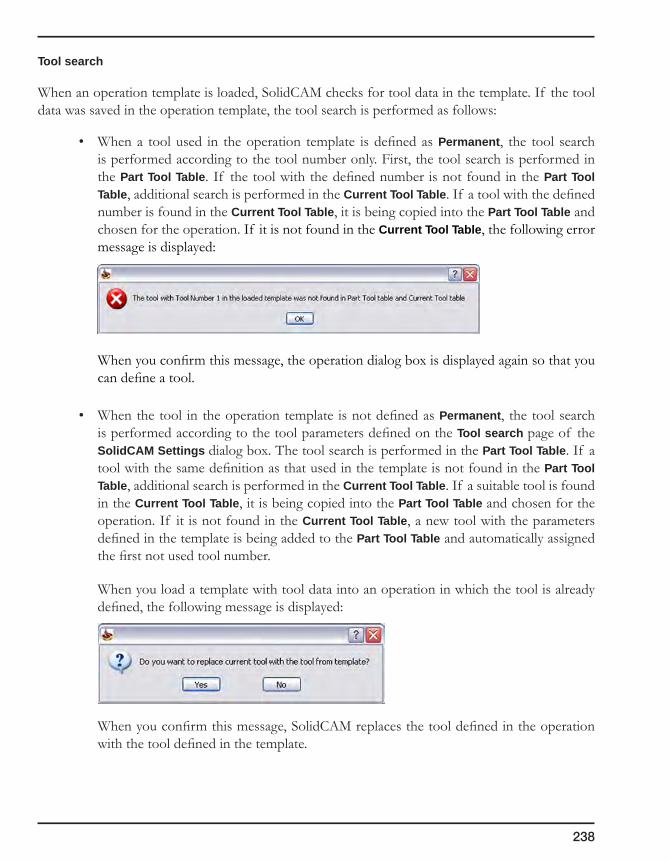
238
Tool search
When an operation template is loaded, SolidCAM checks for tool data in the template. If the tool data was saved in the operation template, the tool search is performed as follows:
• When a tool used in the operation template is defined as Permanent, the tool search is performed according to the tool number only. First, the tool search is performed in the Part Tool Table. If the tool with the defined number is not found in the Part Tool Table, additional search is performed in the Current Tool Table. If a tool with the defined number is found in the Current Tool Table, it is being copied into the Part Tool Table and chosen for the operation. If it is not found in the Current Tool Table, the following error message is displayed:
When you confirm this message, the operation dialog box is displayed again so that you can define a tool.
• When the tool in the operation template is not defined as Permanent, the tool search is performed according to the tool parameters defined on the Tool search page of the SolidCAM Settings dialog box. The tool search is performed in the Part Tool Table. If a tool with the same definition as that used in the template is not found in the Part Tool Table, additional search is performed in the Current Tool Table. If a suitable tool is found in the Current Tool Table, it is being copied into the Part Tool Table and chosen for the operation. If it is not found in the Current Tool Table, a new tool with the parameters defined in the template is being added to the Part Tool Table and automatically assigned the first not used tool number.
When you load a template with tool data into an operation in which the tool is already defined, the following message is displayed:
When you confirm this message, SolidCAM replaces the tool defined in the operation with the tool defined in the template.

239
5. Operations
Creating a new operation from an existing template
SolidCAM enables you create a new operation from an existing template. Right-click on an operation entry in SolidCAM Manager and choose Add Operation from Template from the menu.
The Template Manager dialog box is displayed. This dialog box enables you to choose an existing template. In this case, the Template Manager dialog box displays all the templates existing in the SolidCAM Templates Directory regardless of their type/technology.
When you confirm the dialog box by clicking on the OK button, SolidCAM inserts the chosen operation template into the SolidCAM Manager tree.
The inserted operation is incomplete; it means that the operation has no defined geometry and tool (if the initial operation template used for the operation definition had no tool). The incomplete operations are marked with red color in SolidCAM Manager.
Since the incomplete operations have no geometry, their tool path cannot be generated. In order to completely define the operation, you have to edit it by defining the machining geometry and tool (if necessary).
During creation of a new operation from an operation template, SolidCAM assigns the Machine Coordinate System #1 (Position #1) for the newly created operation. During the operation editing, this Coordinate System can be changed.

240
Process Template
A Process Template is a template of a series of operations that execute a specific machining task. This functionality enables you to store a complete chain of technological operations as a template and apply it for the machining of similar cases.
Defining Process Templates
To create a process template, select in SolidCAM Manager all the names of operations intended to be included in the Template, right-click and choose Create Template.
The Template Manager dialog box is displayed.
This dialog box enables you to save the chosen operations as a process template.
All the process templates existing in the SolidCAM Templates Directory are displayed. The process templates names are listed in the Template Folders section under the Process Templates header. The content of the templates is displayed in the Operation Templates table.
The Include tool data check box enables you to include the tool data into the saved process template.

241
5. Operations
To save the selected operations as a new process template, enter a name in the Process name edit box or choose an existing process template from the Process Templates list and confirm by clicking on the OK button. If a process template with the defined name already exists in the current location, the following warning message is displayed:
When you confirm this warning by clicking on the Yes button, the existing process template is being overwritten with the new one. When you click on the No button, the Template Manager dialog box is displayed again so that you can choose a different name for the process template.
The Template Manager dialog box provides you with the capability to create an empty process template and copy a number of operation templates from different process templates into this empty one.
Using Process Templates
SolidCAM enables you to insert operation templates contained in a process template into a CAM-Part and convert them into regular SolidCAM operations. To insert a process template into the CAM-Part, right-click on the Operations header or on several selected operations in SolidCAM Manager and choose Add Operation from Process Template.
This command displays the Template Manager dialog box that enables you to choose an existing process template to be inserted.

242
During creation of a new operation from the process template, SolidCAM displays the CoordSys selection dialog box that enables you to choose the Coordinate System to be used in the created operations.
The inserted operations are incomplete; it means that the operations have no defined geometry and tool (if the initial operation template used for the operation creation had no tool). The incomplete operations are marked with red color.
Since the incomplete operations have no geometry, their tool path cannot be generated. In order to completely define the operation, you have to edit it by defining the machining geometry and tool (if necessary).
Managing operation/process templates
To manage your operation and process templates, click Manage Templates in the SolidCAM menu.
The Template Manager dialog box is displayed.
The Template Folders section contains the Templates and Process Templates headers.
When the Templates header is selected, all the operation templates located in the SolidCAM Template Directory are displayed in the Operation Templates table.
All the process templates located in the SolidCAM Template Directory are listed under the Process Templates header. When a process template is selected, all the operation templates included in it are displayed in the Operation Templates table.

243
5. Operations
Managing process templates
SolidCAM enables you to manage the process Templates with the right-click menu available on the Process Templates header or on each process template.
This menu provides you with the following commands:
• NewProcessTemplate
This command enables you to create a new empty process Template.
• Rename
This command enables you to rename an existing operation template.
• Delete
This command enables you to delete an existing operation template.
Managing operation templates
SolidCAM enables you to manage operation Templates with the right-click menu available on the Operation Templates table entries. This menu is available for the standalone operation templates located in the SolidCAM Template Directory and for operation templates included into process templates.
• CreateProcessTemplate
This command enables you to create a new process template; the current operation template is added to this process.

244
• Copy
This command enables you to copy the current operation template into the clipboard.
• Paste
This command enables you to paste the operation template from the clipboard. The operation template is inserted into the chosen location (either into the active process template or as a standalone operation template into the into the SolidCAM Template Directory).
• Edit
This command enables you to load the chosen operation template for editing. When a template is loaded, SolidCAM displays the appropriate operation dialog box with the template data.
SolidCAM enables you to edit all the parameters and options of the template, except for the geometry and coordinate system.
The Save Template button enables you to save the template data using the Save template dialog box.
• Delete
This command enables you to delete the active operation template.

245
5. Operations
5.2.3 Info
The button at the right side of the operation dialog box displays a window that contains the information summary of the operation. In this window, the name of the operation, the Tool data and the Milling levels data are listed.
5.2.4 Operation buttons
Save
All settings and parameters of the operation are saved on your disk. The tool path, however, is not calculated. This button enables you to postpone the calculation or to calculate operations in batches.
Use the corresponding commands of SolidCAM Manager to calculate the operation later on.
In the operation list, all operations that have not been calculated are marked with asterisk (*).
Save&Calculate
All settings and parameters of the operation are saved on your disk and the tool path is calculated. After the calculation has been performed, you can exit from the operation dialog box and return to SolidCAM Manager.
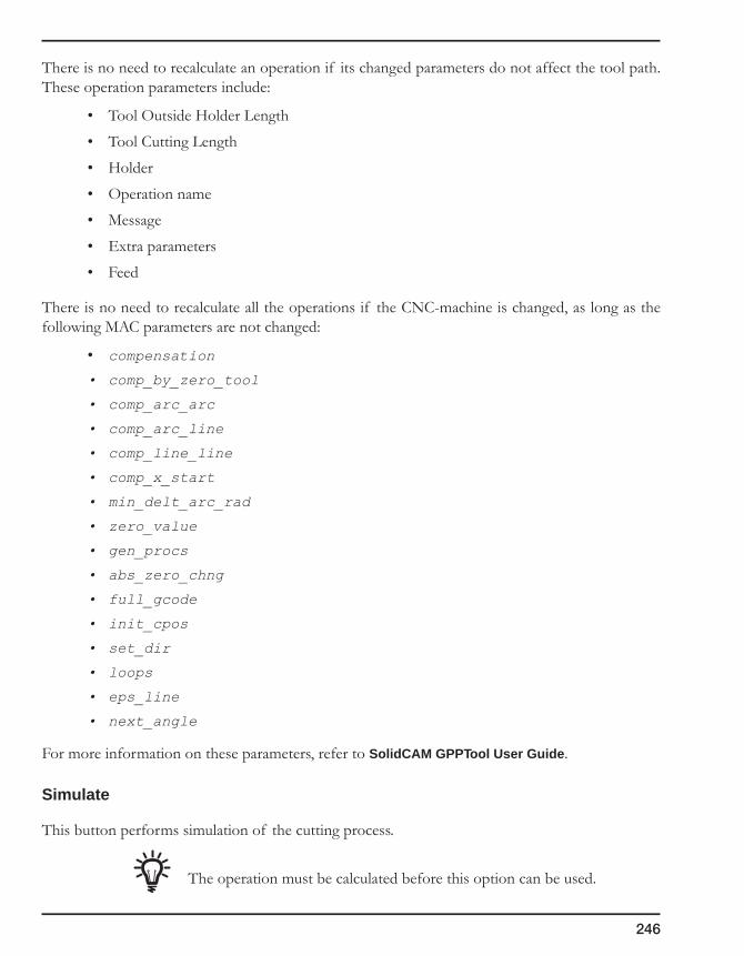
246
There is no need to recalculate an operation if its changed parameters do not affect the tool path. These operation parameters include:
• Tool Outside Holder Length
• Tool Cutting Length
• Holder
• Operation name
• Message
• Extra parameters
• Feed
There is no need to recalculate all the operations if the CNC-machine is changed, as long as the following MAC parameters are not changed:
• compensation
• comp_by_zero_tool
• comp_arc_arc
• comp_arc_line
• comp_line_line
• comp_x_start
• min_delt_arc_rad
• zero_value
• gen_procs
• abs_zero_chng
• full_gcode
• init_cpos
• set_dir
• loops
• eps_line
• next_angle
For more information on these parameters, refer to SolidCAM GPPTool User Guide.
Simulate
This button performs simulation of the cutting process.
The operation must be calculated before this option can be used.
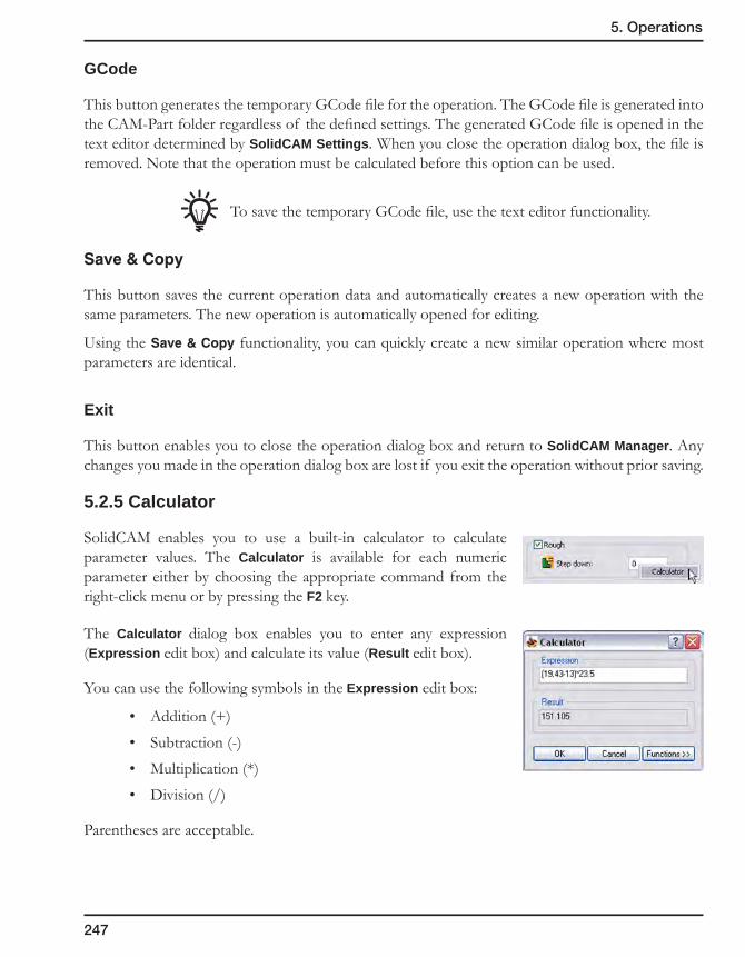
247
5. Operations
GCode
This button generates the temporary GCode file for the operation. The GCode file is generated into the CAM-Part folder regardless of the defined settings. The generated GCode file is opened in the text editor determined by SolidCAM Settings. When you close the operation dialog box, the file is removed. Note that the operation must be calculated before this option can be used.
To save the temporary GCode file, use the text editor functionality.
Save&Copy
This button saves the current operation data and automatically creates a new operation with the same parameters. The new operation is automatically opened for editing.
Using the Save&Copy functionality, you can quickly create a new similar operation where most parameters are identical.
Exit
This button enables you to close the operation dialog box and return to SolidCAM Manager. Any changes you made in the operation dialog box are lost if you exit the operation without prior saving.
5.2.5 Calculator
SolidCAM enables you to use a built-in calculator to calculate parameter values. The Calculator is available for each numeric parameter either by choosing the appropriate command from the right-click menu or by pressing the F2 key.
The Calculator dialog box enables you to enter any expression (Expression edit box) and calculate its value (Result edit box).
You can use the following symbols in the Expression edit box:
• Addition (+)
• Subtraction (-)
• Multiplication (*)
• Division (/)
Parentheses are acceptable.
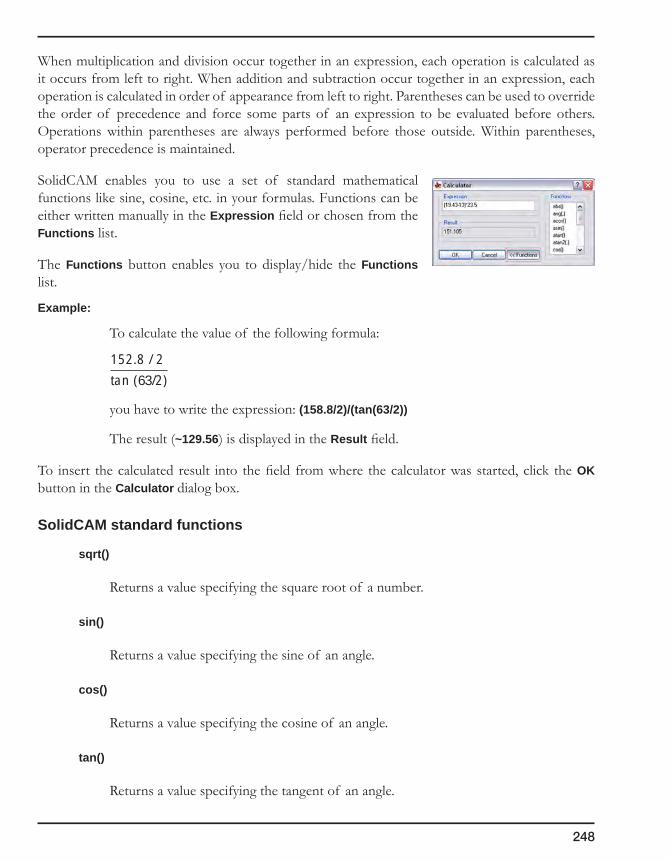
248
When multiplication and division occur together in an expression, each operation is calculated as it occurs from left to right. When addition and subtraction occur together in an expression, each operation is calculated in order of appearance from left to right. Parentheses can be used to override the order of precedence and force some parts of an expression to be evaluated before others. Operations within parentheses are always performed before those outside. Within parentheses, operator precedence is maintained.
SolidCAM enables you to use a set of standard mathematical functions like sine, cosine, etc. in your formulas. Functions can be either written manually in the Expression field or chosen from the Functions list.
The Functions button enables you to display/hide the Functions list.
Example:
To calculate the value of the following formula:
you have to write the expression: (158.8/2)/(tan(63/2))
The result (~129.56) is displayed in the Result field.
To insert the calculated result into the field from where the calculator was started, click the OK button in the Calculator dialog box.
SolidCAM standard functions
sqrt()
Returns a value specifying the square root of a number.
sin()
Returns a value specifying the sine of an angle.
cos()
Returns a value specifying the cosine of an angle.
tan()
Returns a value specifying the tangent of an angle.
152.8 / 2
tan (63/2)
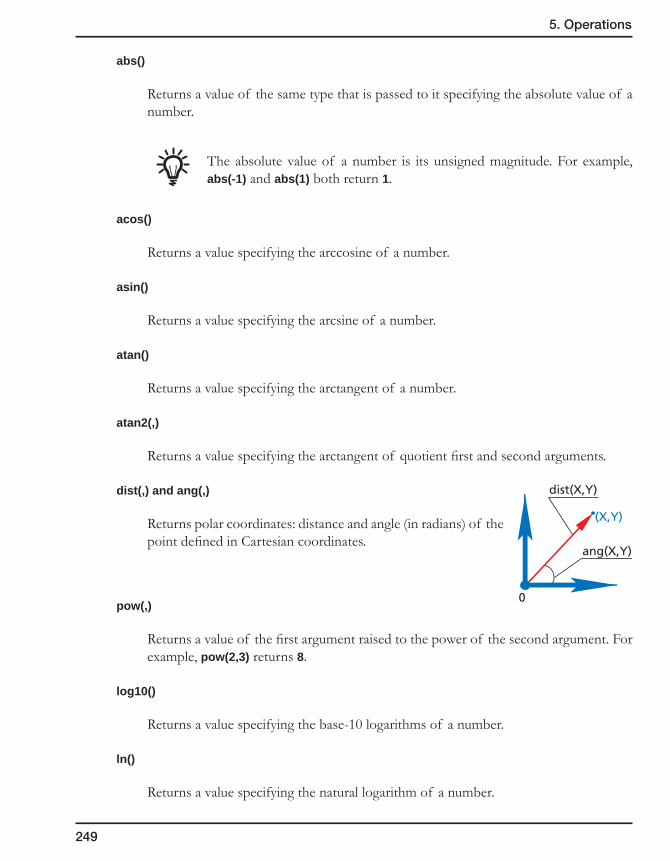
249
5. Operations
abs()
Returns a value of the same type that is passed to it specifying the absolute value of a number.
The absolute value of a number is its unsigned magnitude. For example, abs(-1) and abs(1) both return 1.
acos()
Returns a value specifying the arccosine of a number.
asin()
Returns a value specifying the arcsine of a number.
atan()
Returns a value specifying the arctangent of a number.
atan2(,)
Returns a value specifying the arctangent of quotient first and second arguments.
dist(,) and ang(,)
Returns polar coordinates: distance and angle (in radians) of the point defined in Cartesian coordinates.
pow(,)
Returns a value of the first argument raised to the power of the second argument. For example, pow(2,3) returns 8.
log10()
Returns a value specifying the base-10 logarithms of a number.
ln()
Returns a value specifying the natural logarithm of a number.
(X,Y)
dist(X,Y)
0
ang(X,Y)

250
sum3( , , )
Returns the sum value of three arguments.
int()
Returns the integer portion of a number.
rad()
Converts degrees to radians.
deg()
Converts radians to degrees.
5.2.6 Geometry page
This page enables you to choose the appropriate Coordinate System and to define the Machining Geometry for the operation.
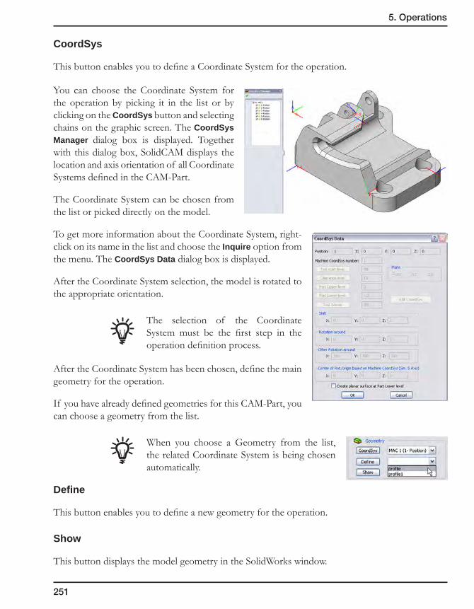
251
5. Operations
CoordSys
This button enables you to define a Coordinate System for the operation.
You can choose the Coordinate System for the operation by picking it in the list or by clicking on the CoordSys button and selecting chains on the graphic screen. The CoordSys Manager dialog box is displayed. Together with this dialog box, SolidCAM displays the location and axis orientation of all Coordinate Systems defined in the CAM-Part.
The Coordinate System can be chosen from the list or picked directly on the model.
To get more information about the Coordinate System, right-click on its name in the list and choose the Inquire option from the menu. The CoordSys Data dialog box is displayed.
After the Coordinate System selection, the model is rotated to the appropriate orientation.
The selection of the Coordinate System must be the first step in the operation definition process.
After the Coordinate System has been chosen, define the main geometry for the operation.
If you have already defined geometries for this CAM-Part, you can choose a geometry from the list.
When you choose a Geometry from the list, the related Coordinate System is being chosen automatically.
Define
This button enables you to define a new geometry for the operation.
Show
This button displays the model geometry in the SolidWorks window.
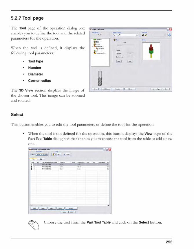
252
5.2.7 Tool page
The Tool page of the operation dialog box enables you to define the tool and the related parameters for the operation.
When the tool is defined, it displays the following tool parameters:
• Tooltype
• Number
• Diameter
• Cornerradius
The 3D View section displays the image of the chosen tool. This image can be zoomed and rotated.
Select
This button enables you to edit the tool parameters or define the tool for the operation.
• When the tool is not defined for the operation, this button displays the View page of the Part Tool Table dialog box that enables you to choose the tool from the table or add a new one.
Choose the tool from the Part Tool Table and click on the Select button.
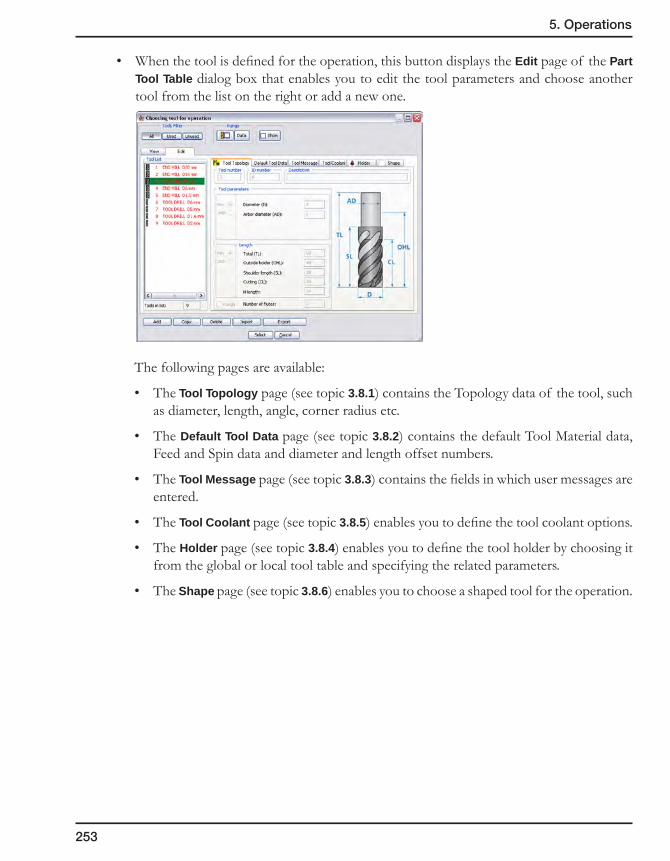
253
5. Operations
• When the tool is defined for the operation, this button displays the Edit page of the Part Tool Table dialog box that enables you to edit the tool parameters and choose another tool from the list on the right or add a new one.
The following pages are available:
• The Tool Topology page (see topic 3.8.1) contains the Topology data of the tool, such as diameter, length, angle, corner radius etc.
• The Default Tool Data page (see topic 3.8.2) contains the default Tool Material data, Feed and Spin data and diameter and length offset numbers.
• The Tool Message page (see topic 3.8.3) contains the fields in which user messages are entered.
• The Tool Coolant page (see topic 3.8.5) enables you to define the tool coolant options.
• The Holder page (see topic 3.8.4) enables you to define the tool holder by choosing it from the global or local tool table and specifying the related parameters.
• The Shape page (see topic 3.8.6) enables you to choose a shaped tool for the operation.
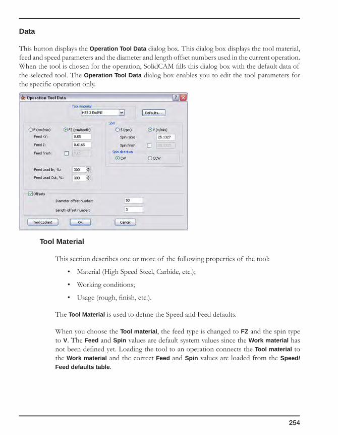
254
Data
This button displays the Operation Tool Data dialog box. This dialog box displays the tool material, feed and speed parameters and the diameter and length offset numbers used in the current operation. When the tool is chosen for the operation, SolidCAM fills this dialog box with the default data of the selected tool. The Operation Tool Data dialog box enables you to edit the tool parameters for the specific operation only.
Tool Material
This section describes one or more of the following properties of the tool:
• Material (High Speed Steel, Carbide, etc.);
• Working conditions;
• Usage (rough, finish, etc.).
The Tool Material is used to define the Speed and Feed defaults.
When you choose the Tool material, the feed type is changed to FZ and the spin type to V. The Feed and Spin values are default system values since the Work material has not been defined yet. Loading the tool to an operation connects the Tool material to the Work material and the correct Feed and Spin values are loaded from the Speed/Feed defaults table.
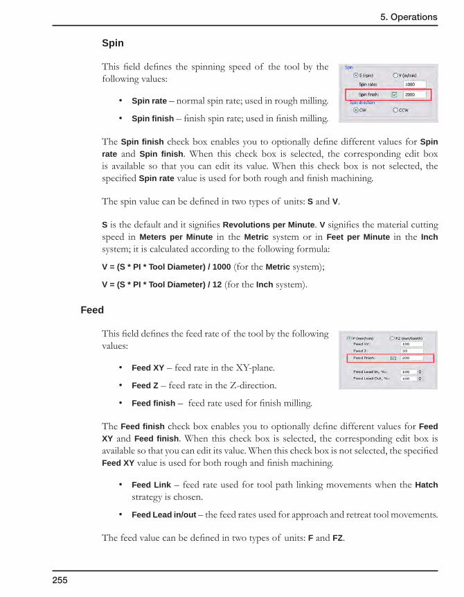
255
5. Operations
Spin
This field defines the spinning speed of the tool by the following values:
• Spin rate – normal spin rate; used in rough milling.
• Spin finish – finish spin rate; used in finish milling.
The Spin finish check box enables you to optionally define different values for Spin rate and Spin finish. When this check box is selected, the corresponding edit box is available so that you can edit its value. When this check box is not selected, the specified Spin rate value is used for both rough and finish machining.
The spin value can be defined in two types of units: S and V.
S is the default and it signifies Revolutions per Minute. V signifies the material cutting speed in Meters per Minute in the Metric system or in Feet per Minute in the Inch system; it is calculated according to the following formula:
V = (S * PI * Tool Diameter) / 1000 (for the Metric system);
V = (S * PI * Tool Diameter) / 12 (for the Inch system).
Feed
This field defines the feed rate of the tool by the following values:
• Feed XY – feed rate in the XY-plane.
• Feed Z – feed rate in the Z-direction.
• Feed finish – feed rate used for finish milling.
The Feed finish check box enables you to optionally define different values for Feed XY and Feed finish. When this check box is selected, the corresponding edit box is available so that you can edit its value. When this check box is not selected, the specified Feed XY value is used for both rough and finish machining.
• Feed Link – feed rate used for tool path linking movements when the Hatch strategy is chosen.
• Feed Lead in/out – the feed rates used for approach and retreat tool movements.
The feed value can be defined in two types of units: F and FZ.

256
F is the default and it signifies Units per minute. FZ signifies Units per tooth and is calculated according to the following formula:
FZ = F/(Number of Flutes * S)
3D Model - Entry only
When this check box is selected, the defined Feed Z is used for vertical movements only. When this check box is not selected, the defined Feed Z is used for all movements when the Z-coordinate changes.
This option is available only for the 3D Milling operation.
Diameter offset number
This parameter defines the number of the Diameter Offset Register of the current tool in the Offset table of the CNC-machine.
Length offset number
This parameter defines the number of the Length Offset Register of the current tool in the Offset table of the CNC-machine.
Second offset number
This parameter defines the register number of the upper cutting face offset, in the offset table of the CNC-machine. This option enables SolidCAM to automatically take into account the minor size differences between the defined tool and the one actually used for cutting the workpiece, if there are any. You may choose not to use this option by clearing the check box.
This option is available only for the T-Slot operation.

257
5. Operations
5.2.8 Levels page
This page enables you to specify the Z-levels at which the tool movements are executed. The default input values of these parameters are the CAM-Part values that you have specified in the CoordSys Data dialog box.
To define the Milling levels, enter the values or use the appropriate buttons to pick the Z-levels on your 3D model.
Start level
This option defines the Z-level that can be optionally used for interoperational movements.
The Start level button and the related edit box are available only if the Operation Start level option is chosen in Part Settings (see topic 2.10.2).
The default Start level value is equal to the Part Clearance level value of the Coordinate System chosen for the operation.
The Start level cannot be lower than the Operation Clearance level. If you are trying to save the operation in which the defined Start level is lower than the Operation Clearance level, the error message is displayed:

258
Clearance level
This option defines the Z-level to which the tool retreats when it moves from one cut to another.
Safety distance
This option defines the distance to the Upper level at which the tool starts moving at the Z feed rate you have entered for the tool. Movements from the Clearance level to this height are performed in the rapid mode.
Upper level
This option defines the Z-level at which the machining starts.
Lower level (Depth)
This option defines the Z-level below which the tool does not mill in any milling strategy.
Delta depth
Delta depth is the offset for the cutting depth that can be changed with its associativity preserved. This parameter is always relative to the Depth defined for the operation.
If the Delta depth value is positive, a blue arrow is displayed near its field indicating a positive offset value (in the positive direction of the Z-axis).
If the Delta depth value is negative, a red arrow is displayed near its field indicating a negative offset value (in the negative direction of the Z-axis).
The value of these parameters is the Z-coordinate. These parameters can be defined either by entering the value in the edit box or by picking a point on the solid model (except for Safety distance). In the latter case, the parameters are associative to the solid model. Associativity enables SolidCAM to be synchronized with the solid model changes. SolidCAM automatically updates the CAM data when the model is modified.

259
5. Operations
Depth associativity
The following operation parameters are associative to the SolidWorks model.
• Clearancelevel
• Upperlevel
• Lowerlevel
SolidCAM enables you to define these parameters by picking the entities on the solid model.
The Depth parameter used in some operations (Profile, Pocket, etc.) is indirectly associative. You have two possibilities:
• To define Depth by manual input.
• To define Lower level by picking on the model. In this case, Depth is calculated automatically. The associativity is established in Lower level. When either Upper level or Lower level is synchronized, Depth is updated.
The associativity is saved only for the following picked items:
• Vertex
• Sketch point
• Reference point
• Part origin
• Planar face parallel to the XY-plane of the current Coordinate System
• Plane parallel to the XY-plane of the current Coordinate System
The Pick Lower level dialog box displays the Z-coordinate of the picked point. If the value is associative to the model, the edit box is highlighted in pink.
When the parameter is defined by picking model entities, SolidCAM displays the Z-coordinate of the picked point in the related edit box. The background of the edit box changes. The value displayed in this edit box is associative to the solid model.
When you type in this edit box, the associativity is removed.

260
The associative parameters are displayed in SolidCAM Manager under the operation name.
When the parameters are not synchronized, the parameters and the parent operation are marked with the synchronization mark .
The synchronization commands are available for operations in the right-click menu.
• The Synchronize command enables you to synchronize the values of the parameters with the updated model.
• The Synchronize&Calculate command enables you to synchronize the values of the parameters with the updated model and calculate the operation after the synchronization.

261
5. Operations
• The Check Synchronization command enables you to check the model for updates affecting the specified parameter.
• The Break Z-Levels Associativity/Break associativity command enables you to break the associativity between Z-Levels parameters and the solid model. The confirmation message is displayed.
• The Show command highlights the model entity with which the depth parameter is associated. The Show Geometry dialog box is displayed. The Exit button enables you to return to the normal model view.
When the synchronization fails, SolidCAM marks the operation and the parameters with the exclamation mark.
The parameters definition can be edited in the operation dialog box. You have to either type the necessary values or redefine the points on the model. In the first case, the associativity is removed.
Interoperational tool movements
SolidCAM enables you to perform the interoperational tool movements either through the Part Clearance level (same for all operations of the CAM-Part) or through the Operation Start level (can be different from the Part Clearance Level and vary for each operation).
Interoperational tool through Part Clearance level
SolidCAM performs the interoperational movements through Part Clearance level when two neighboring operations use the same Tool (and Tool offset) and Coordinate System.
Operation Clearance Level
Rapid movements
Feed movements
Part Clearance Level
Safety distance
Safety distance
Machininglevels
OperationClearance Level
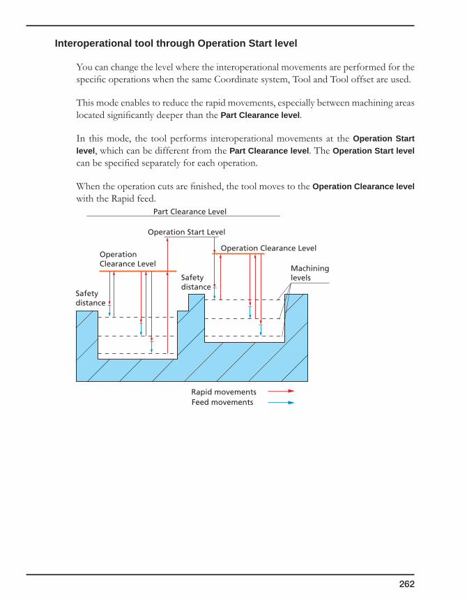
262
Interoperational tool through Operation Start level
You can change the level where the interoperational movements are performed for the specific operations when the same Coordinate system, Tool and Tool offset are used.
This mode enables to reduce the rapid movements, especially between machining areas located significantly deeper than the Part Clearance level.
In this mode, the tool performs interoperational movements at the Operation Start level, which can be different from the Part Clearance level. The Operation Start level can be specified separately for each operation.
When the operation cuts are finished, the tool moves to the Operation Clearance level with the Rapid feed.
Operation Clearance Level
Rapid movementsFeed movements
Part Clearance Level
Operation Start Level
Safetydistance
Safetydistance
Machininglevels
Operation Clearance Level

263
5. Operations
If the Start level of the next operation is higher than the Operation Clearance level, the tool ascends to the Start level of the next operation, then performs XY-movement and descends to the Operation Clearance level of the next operation. All these movements are performed with the Rapid feed. The tool will then perform the rapid movement to the Safety Distance level of the first cut and start the descent to the first cut with the working feed.
If the Start level of the next operation is lower than the Operation Clearance level, the tool performs the XY-movements at the Operation Clearance level and than descends to Clearance level of the next operation without stopping at the Start level. All these movements are performed with the Rapid feed. The tool then performs the rapid movement to the Safety Distance level of the first cut and starts the descent to the first cut with the working feed.
Previous Operation Clearance Level
Rapid movementsFeed movements
Next Operation Start Level
OperationLast cut
OperationFirst cut
Safety distance
Next Operation Clearance Level
Previous Operation Clearance Level
Rapid movements
Feed movements
Next Operation Start Level
Operation Last cut
Safetydistance
Next Operation Clearance Level
OperationFirst cut

264
All of these rules are relevant only when there is no Tool change, Tool offset change and Coordinate System change between the operations. If there are such changes, the Operation Start level is ignored and SolidCAM performs the tool movement through the Part Clearance level.
5.2.9 Technology page
This page enables you to define the technological parameters such as offsets, roughing and finishing data, depth type, etc.
5.2.10 Advanced Technology page
This page contains the infrequently used parameters and options whose definition is required only in particular machining cases.
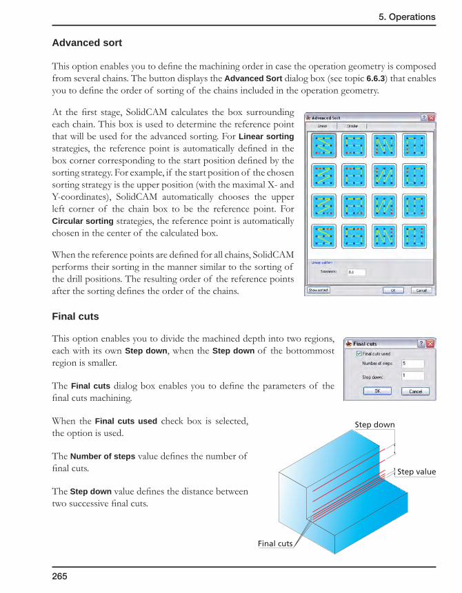
265
5. Operations
Advanced sort
This option enables you to define the machining order in case the operation geometry is composed from several chains. The button displays the Advanced Sort dialog box (see topic 6.6.3) that enables you to define the order of sorting of the chains included in the operation geometry.
At the first stage, SolidCAM calculates the box surrounding each chain. This box is used to determine the reference point that will be used for the advanced sorting. For Linear sorting strategies, the reference point is automatically defined in the box corner corresponding to the start position defined by the sorting strategy. For example, if the start position of the chosen sorting strategy is the upper position (with the maximal X- and Y-coordinates), SolidCAM automatically chooses the upper left corner of the chain box to be the reference point. For Circular sorting strategies, the reference point is automatically chosen in the center of the calculated box.
When the reference points are defined for all chains, SolidCAM performs their sorting in the manner similar to the sorting of the drill positions. The resulting order of the reference points after the sorting defines the order of the chains.
Final cuts
This option enables you to divide the machined depth into two regions, each with its own Step down, when the Step down of the bottommost region is smaller.
The Final cuts dialog box enables you to define the parameters of the final cuts machining.
When the Final cuts used check box is selected, the option is used.
The Number of steps value defines the number of final cuts.
The Step down value defines the distance between two successive final cuts.
Step down
Final cuts
Step value
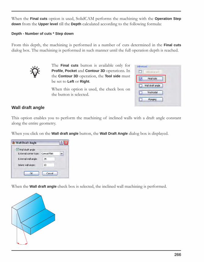
266
When the Final cuts option is used, SolidCAM performs the machining with the Operation Step down from the Upper level till the Depth calculated according to the following formula:
Depth - Number of cuts * Step down
From this depth, the machining is performed in a number of cuts determined in the Final cuts dialog box. The machining is performed in such manner until the full operation depth is reached.
The Final cuts button is available only for Profile, Pocket and Contour 3D operations. In the Contour 3D operation, the Tool side must be set to Left or Right.
When this option is used, the check box on the button is selected.
Wall draft angle
This option enables you to perform the machining of inclined walls with a draft angle constant along the entire geometry.
When you click on the Wall draft angle button, the Wall Draft Angle dialog box is displayed.
When the Wall draft angle check box is selected, the inclined wall machining is performed.
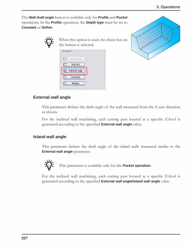
267
5. Operations
The Wall draft angle button is available only for Profile and Pocket operations. In the Profile operation, the Depth type must be set to Constant or Define.
When this option is used, the check box on the button is selected.
External wall angle
This parameter defines the draft angle of the wall measured from the Z-axis direction as shown.
For the inclined wall machining, each cutting pass located at a specific Z-level is generated according to the specified External wall angle value.
Island wall angle
This parameter defines the draft angle of the island walls measured similar to the External wall angle parameter.
This parameter is available only for the Pocket operation.
For the inclined wall machining, each cutting pass located at a specific Z-level is generated according to the specified External wall angle/Island wall angle value.
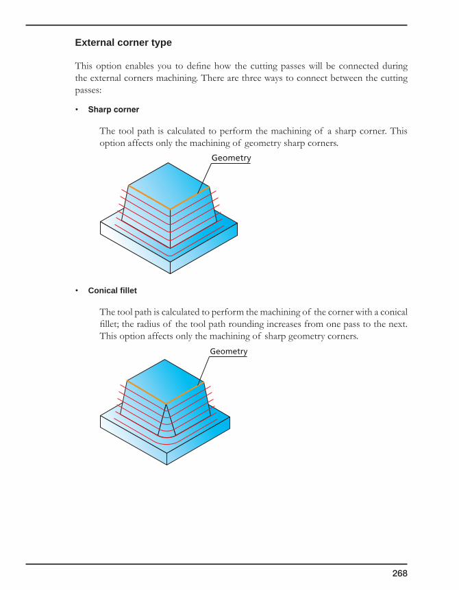
268
External corner type
This option enables you to define how the cutting passes will be connected during the external corners machining. There are three ways to connect between the cutting passes:
• Sharpcorner
The tool path is calculated to perform the machining of a sharp corner. This option affects only the machining of geometry sharp corners.
• Conical fillet
The tool path is calculated to perform the machining of the corner with a conical fillet; the radius of the tool path rounding increases from one pass to the next. This option affects only the machining of sharp geometry corners.
Geometry
Geometry
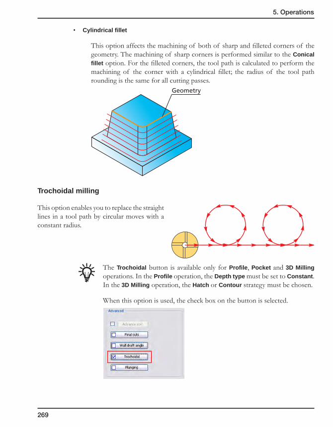
269
5. Operations
• Cylindrical fillet
This option affects the machining of both of sharp and filleted corners of the geometry. The machining of sharp corners is performed similar to the Conical fillet option. For the filleted corners, the tool path is calculated to perform the machining of the corner with a cylindrical fillet; the radius of the tool path rounding is the same for all cutting passes.
Trochoidal milling
This option enables you to replace the straight lines in a tool path by circular moves with a constant radius.
The Trochoidal button is available only for Profile, Pocket and 3D Milling operations. In the Profile operation, the Depth type must be set to Constant. In the 3D Milling operation, the Hatch or Contour strategy must be chosen.
When this option is used, the check box on the button is selected.
Geometry

270
Potential benefits include:
• Fastermetalremoval
Making the constant circular curve the only direction change enables a high feed rate to be consistently maintained.
• Longertoollife
The cutting edge is in contact with the material through only about 5% of the cutter’s revolution vs. up to 50% for more conventional cutting. Cooling of the tool is improved.
The Trochoidal dialog box enables you to define the parameters of trochoidal milling.
• Radius
This field defines the radius of the circle that describes the movement of the tool.
• Step
This field defines the distance between the centers of two adjacent circles that describe the tool movement.
• Engagement angle
This field defines the angle measured between two vectors describing the area of contact between the tool and the machined material.
During the calculation, SolidCAM checks the engagement angle at each tool position defined by the Step parameter. If the engagement angle is greater than the specified Engagement angle value, SolidCAM at this position performs a circular tool movement with the radius defined by the Radius parameter. If the engagement angle is smaller than the specified Engagement angle value, SolidCAM does not generate a circular movement at this position; the tool moves to the next position.
Step
Tool trajectoryRadius
Engagement angle
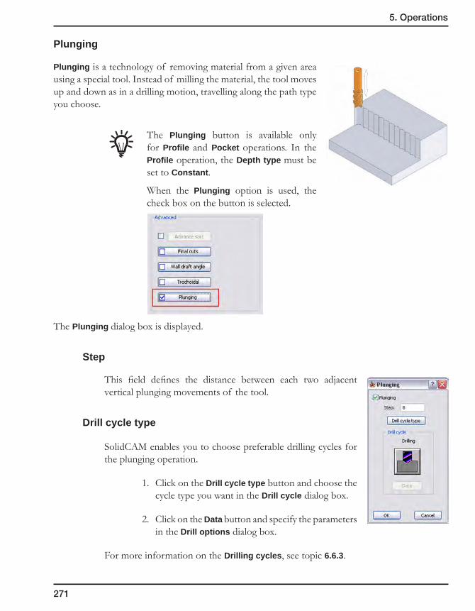
271
5. Operations
Plunging
Plunging is a technology of removing material from a given area using a special tool. Instead of milling the material, the tool moves up and down as in a drilling motion, travelling along the path type you choose.
The Plunging button is available only for Profile and Pocket operations. In the Profile operation, the Depth type must be set to Constant.
When the Plunging option is used, the check box on the button is selected.
The Plunging dialog box is displayed.
Step
This field defines the distance between each two adjacent vertical plunging movements of the tool.
Drill cycle type
SolidCAM enables you to choose preferable drilling cycles for the plunging operation.
1. Click on the Drill cycle type button and choose the cycle type you want in the Drill cycle dialog box.
2. Click on the Data button and specify the parameters in the Drill options dialog box.
For more information on the Drilling cycles, see topic 6.6.3.
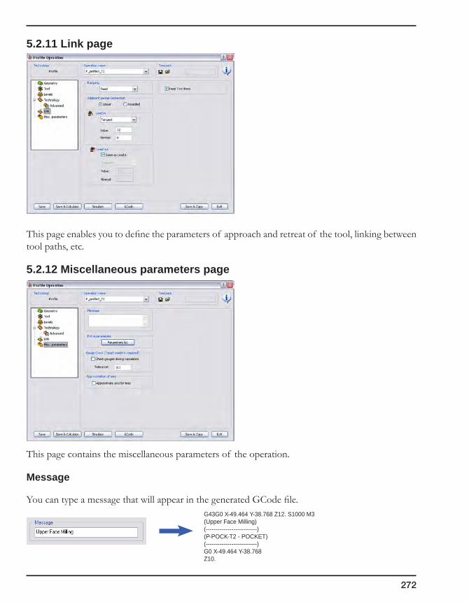
272
5.2.11 Link page
This page enables you to define the parameters of approach and retreat of the tool, linking between tool paths, etc.
5.2.12 Miscellaneous parameters page
This page contains the miscellaneous parameters of the operation.
Message
You can type a message that will appear in the generated GCode file.G43G0 X-49.464 Y-38.768 Z12. S1000 M3(Upper Face Milling)(--------------------------)(P-POCK-T2 - POCKET)(--------------------------)G0 X-49.464 Y-38.768Z10.

273
5. Operations
Extra parameters
This field is available only when special operation options have been implemented in the post-processor you are using for this CAM-Part.
Click on the Parameters list button. The Operation Options dialog box is displayed with the additional parameters defined in the post-processor.
Gouge check
This option enables you to perform gouge checking after the calculation of 2.5D Milling operations. During this checking, SolidCAM detects all the gouges between the tool and the target model and informs about the positions where these gouges occur.
The Check gouges during calculation check box enables you to perform the gouge checking directly after the tool path calculation. You can also define the gouge checking tolerance in the corresponding edit box. If gouges are detected during this checking, SolidCAM informs you about their location on the model by displaying the coordinates in the Check gouges dialog box and dots showing the gouge positions on the model in the graphic area.
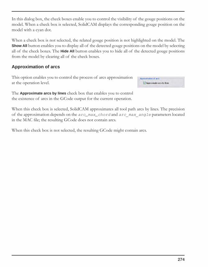
274
In this dialog box, the check boxes enable you to control the visibility of the gouge positions on the model. When a check box is selected, SolidCAM displays the corresponding gouge position on the model with a cyan dot.
When a check box is not selected, the related gouge position is not highlighted on the model. The Show All button enables you to display all of the detected gouge positions on the model by selecting all of the check boxes. The Hide All button enables you to hide all of the detected gouge positions from the model by clearing all of the check boxes.
Approximation of arcs
This option enables you to control the process of arcs approximation at the operation level.
The Approximate arcs by lines check box that enables you to control the existence of arcs in the GCode output for the current operation.
When this check box is selected, SolidCAM approximates all tool path arcs by lines. The precision of the approximation depends on the arc_max_chord and arc_max_angle parameters located in the MAC file; the resulting GCode does not contain arcs.
When this check box is not selected, the resulting GCode might contain arcs.

275
5. Operations
5.3 Working with operations
Some of the operation commands affect all existing operations, others can only be applied to one or more selected operations. SolidCAM produces different menus, depending on whether you right-click on the Operations header in SolidCAM Manager or on an existing operation in the list.
In SolidCAM Manager, right-click on the Operations header. The operations menu is displayed.
If you right-click on an existing operation, the operation commands are displayed.
5.3.1 Add Operation
This command enables you to add a new operation to your CAM-Part. In SolidCAM, an operation is a single machining step. Normally, you manufacture a workpiece using several machining steps and technologies. For each of these steps you can define a separate operation. An operation can be very complex, but always uses one tool, one major geometry and executes one machining type, e.g. 3D milling, profile milling or drilling.
You can edit any single machining operation, change the operation sequence and generate the GCode, combine and split the operation list of your CAM-Part.
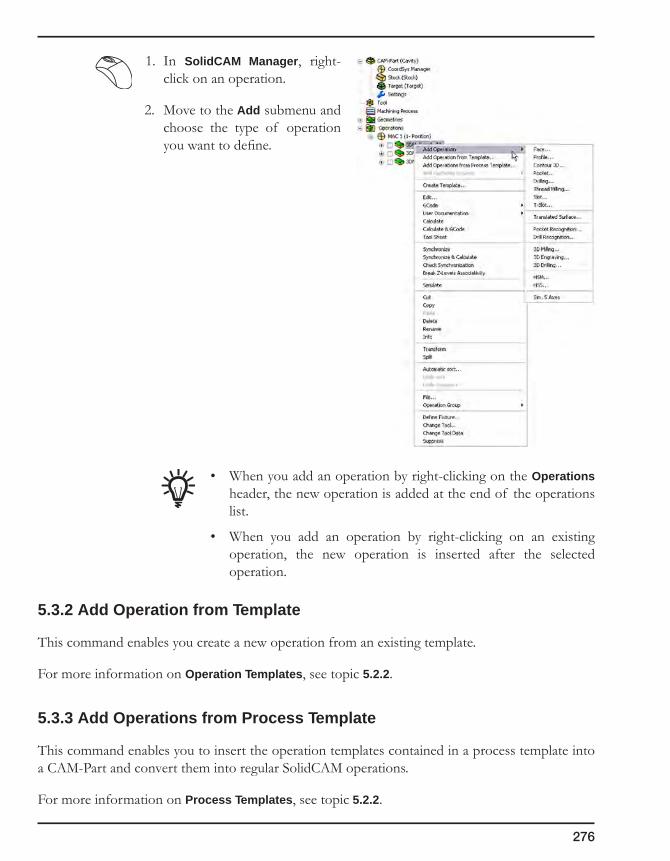
276
1. In SolidCAM Manager, right-click on an operation.
2. Move to the Add submenu and choose the type of operation you want to define.
• When you add an operation by right-clicking on the Operations header, the new operation is added at the end of the operations list.
• When you add an operation by right-clicking on an existing operation, the new operation is inserted after the selected operation.
5.3.2 Add Operation from Template
This command enables you create a new operation from an existing template.
For more information on Operation Templates, see topic 5.2.2.
5.3.3 Add Operations from Process Template
This command enables you to insert the operation templates contained in a process template into a CAM-Part and convert them into regular SolidCAM operations.
For more information on Process Templates, see topic 5.2.2.
277
5. Operations
5.3.4 Add Machining Process
This command enables you to use a previously created Machining Process in your CAM-Part.
For more information on Machining Processes, refer to chapter 8.
5.3.5 Create Template
This command displays the Template Manager dialog box that enables you to save operation data as a template.
When this option is applied to several selected operations, a process template is created with all the selected operations included.
For more information on Operation Templates and Process Templates, see topic 5.2.2.
5.3.6 Edit
This command enables you to view or change the definition and parameters of an existing operation. If you select this command, the corresponding operation dialog box is displayed and you can change the operation definition.
5.3.7 Calculate/Calculate All
Before you are able to generate the GCode for your CNC-machine, you have to perform the tool path calculation. Based on the geometries, machining strategy and technological parameters you have defined and saved in the operations, SolidCAM calculates the movements of the tool.
If you expect a long tool path calculation time, mainly in 3D Milling operations, it is advisable to define your operations, save them and postpone the tool path calculation. This function enables you to calculate large CAM-Parts with many operations in a batch routine e.g. overnight.
5.3.8 GCode/GCode All
The commands in this submenu enable you to generate, list, copy or print NC-programs.
For more information on generating the GCode, refer to chapter 11.
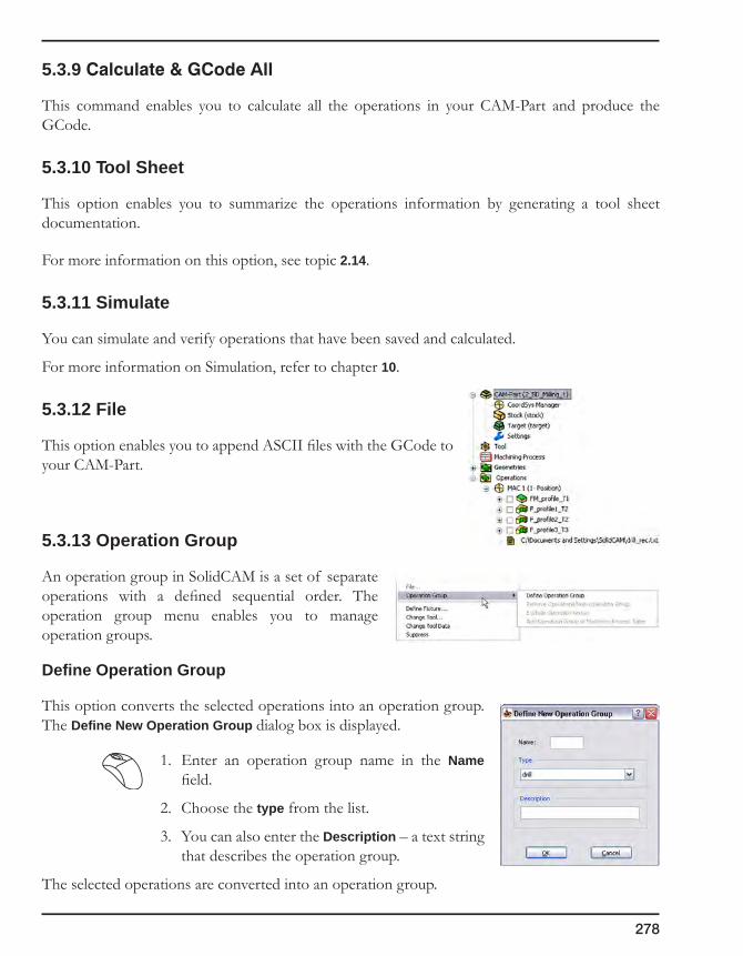
278
5.3.9Calculate&GCodeAll
This command enables you to calculate all the operations in your CAM-Part and produce the GCode.
5.3.10 Tool Sheet
This option enables you to summarize the operations information by generating a tool sheet documentation.
For more information on this option, see topic 2.14.
5.3.11 Simulate
You can simulate and verify operations that have been saved and calculated.
For more information on Simulation, refer to chapter 10.
5.3.12 File
This option enables you to append ASCII files with the GCode to your CAM-Part.
5.3.13 Operation Group
An operation group in SolidCAM is a set of separate operations with a defined sequential order. The operation group menu enables you to manage operation groups.
Define Operation Group
This option converts the selected operations into an operation group. The Define New Operation Group dialog box is displayed.
1. Enter an operation group name in the Name field.
2. Choose the type from the list.
3. You can also enter the Description – a text string that describes the operation group.
The selected operations are converted into an operation group.

279
5. Operations
Add Operation Group to Machining Process Table
This option enables you to insert the selected operation group into the current Machining Process Table.
When the operation group is added, the following message is displayed:
Remove Operations from Operation Group
This option removes the selected operation from the operation group.
Explode Operation Group
This option turns the operation group into single operations.
5.3.14 Cut/Copy/Paste
SolidCAM enables you to cut, copy and paste operations.
• The Copy command copies the selected operations into the clipboard.
• The Paste command inserts the operations from the clipboard, after the selected operation. The pasted operations are marked by an asterisk; they must be calculated to obtain the tool path.
If the clipboard is empty, the Paste command is unavailable.
• The Cut command cuts the operations and copies them into the clipboard. When the operations are pasted from the clipboard, the source operations are removed.
5.3.15 Rename
SolidCAM enables you to rename a specific operation. Right-click on the operation name in SolidCAM Manager and choose the Rename command from the menu.
The Operation Rename dialog box is displayed. This dialog box enables you to assign a new name to the operation.
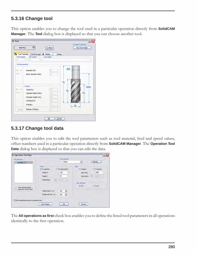
280
5.3.16 Change tool
This option enables you to change the tool used in a particular operation directly from SolidCAM Manager. The Tool dialog box is displayed so that you can choose another tool.
5.3.17 Change tool data
This option enables you to edit the tool parameters such as tool material, feed and speed values, offset numbers used in a particular operation directly from SolidCAM Manager. The Operation Tool Data dialog box is displayed so that you can edit the data.
The All operations as first check box enables you to define the listed tool parameters in all operations identically to the first operation.
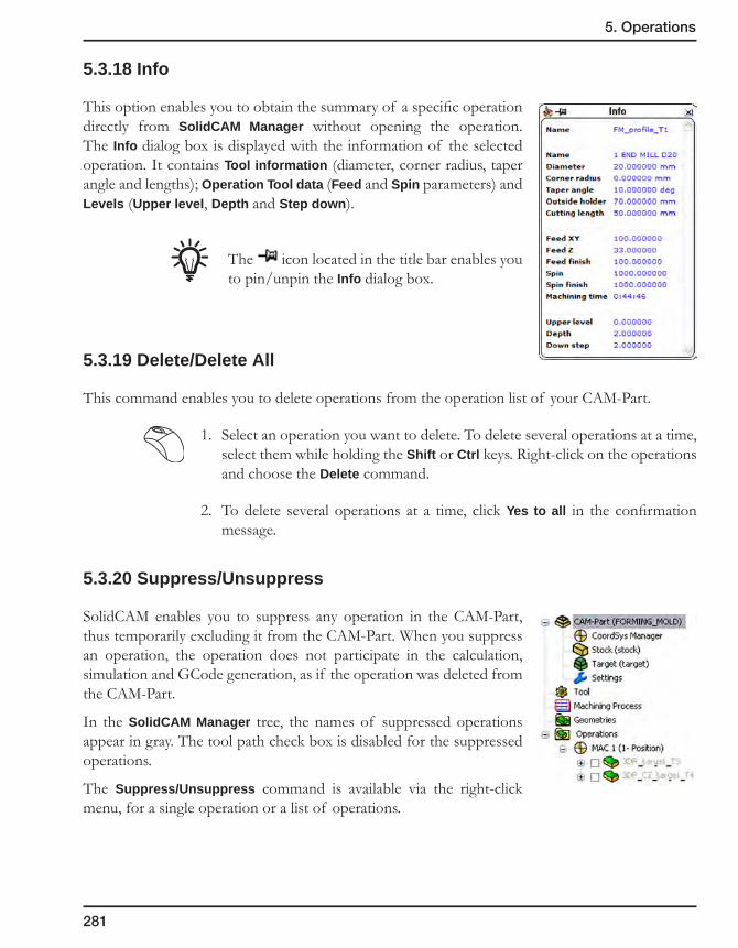
281
5. Operations
5.3.18 Info
This option enables you to obtain the summary of a specific operation directly from SolidCAM Manager without opening the operation. The Info dialog box is displayed with the information of the selected operation. It contains Tool information (diameter, corner radius, taper angle and lengths); Operation Tool data (Feed and Spin parameters) and Levels (Upper level, Depth and Step down).
The icon located in the title bar enables you to pin/unpin the Info dialog box.
5.3.19 Delete/Delete All
This command enables you to delete operations from the operation list of your CAM-Part.
1. Select an operation you want to delete. To delete several operations at a time, select them while holding the Shift or Ctrl keys. Right-click on the operations and choose the Delete command.
2. To delete several operations at a time, click Yes to all in the confirmation message.
5.3.20 Suppress/Unsuppress
SolidCAM enables you to suppress any operation in the CAM-Part, thus temporarily excluding it from the CAM-Part. When you suppress an operation, the operation does not participate in the calculation, simulation and GCode generation, as if the operation was deleted from the CAM-Part.
In the SolidCAM Manager tree, the names of suppressed operations appear in gray. The tool path check box is disabled for the suppressed operations.
The Suppress/Unsuppress command is available via the right-click menu, for a single operation or a list of operations.

282
When the selected operations are not suppressed, right-click on the list of selected operations and choose Suppress. All selected operations are suppressed.
When the selected operations are suppressed, the Unsuppress command available in the right-click operation menu unsuppresses the selected operations.
When the list of selected operations contains both suppressed and unsuppressed operations, both Suppress and Unsuppress commands are available in the right-click menu. The Suppress command suppresses all the unsuppressed operations in the list. The Unsuppress command unsuppresses all the suppressed operations in the list.
Editing suppressed operations
SolidCAM enables you to edit a suppressed operation. However, the Save&Calculate, Simulate and GCode buttons are unavailable.

283
5. Operations
Tool path
When an operation is suppressed, SolidCAM re-generates the CAM-Part tool path to exclude the tool path data related to the suppressed operations.
The tool path stays unchanged till the parameters of the operation are updated.
During the unsuppressing of the suppressed operation, the CAM-Part tool path is re-generated in order to include the data of the unsuppressed operations.
Suppressing linked operations
3D Drilling operation + 3D Milling operation
When the Suppress command is applied to the 3D Drilling operation, the result is the following:
• The 3D Drilling operation is suppressed;
• The tool path of the related 3D Milling operation is removed and the operation appears marked with asterisk.
When the Suppress command is applied to the 3D Milling operation, only this operation is suppressed. Both 3D Milling and related 3D Drilling operations must be selected in order to be suppressed together.
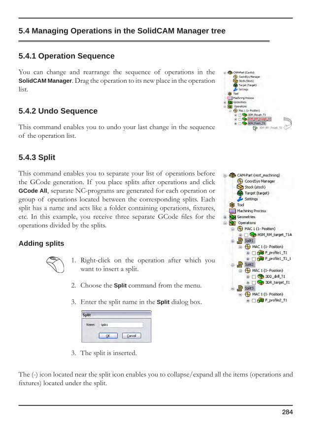
284
5.4 Managing Operations in the SolidCAM Manager tree
5.4.1 Operation Sequence
You can change and rearrange the sequence of operations in the SolidCAM Manager. Drag the operation to its new place in the operation list.
5.4.2 Undo Sequence
This command enables you to undo your last change in the sequence of the operation list.
5.4.3 Split
This command enables you to separate your list of operations before the GCode generation. If you place splits after operations and click GCode All, separate NC-programs are generated for each operation or group of operations located between the corresponding splits. Each split has a name and acts like a folder containing operations, fixtures, etc. In this example, you receive three separate GCode files for the operations divided by the splits.
Adding splits
1. Right-click on the operation after which you want to insert a split.
2. Choose the Split command from the menu.
3. Enter the split name in the Split dialog box.
3. The split is inserted.
The (-) icon located near the split icon enables you to collapse/expand all the items (operations and fixtures) located under the split.

285
5. Operations
Managing splits
• Add
This command enables you to add an operation to the list of operations that belong to the current split.
• AddMachiningProcess
This command enables you to add a Machining Process to the list of operations that belong to the current split.
• GCode
These commands enable you to generate and list GCode files for the operations that belong to the chosen split. The GCode file generated for each split is automatically saved in the CAM-Part folder.

286
• Userdocumentation
These commands enable you to generate and edit the documentation that contains the data about the operations that belong to the current split.
• Delete
This command enables you to delete a split item. The confirmation message is displayed. Confirm it by clicking on the Yes button.
• Rename
This command enables you to edit the split name in the Split dialog box.
• Suppress/Unsuppress
This command enables you to suppress/unsuppress the split with all of its contents.
Just like re-sequencing operations, you can move a split mark to another location in the operation list. Drag the split mark on the operation after which you want to insert it.
5.4.4 Expand tree
This command enables you to open the operation list so that all the geometries used in each operation are displayed in the tree structure of SolidCAM Manager.
5.4.5 Collapse tree
This command enables you to reduce the operation list so that only the operation names are displayed in the tree structure of SolidCAM Manager.
5.4.6 Show/Hide Tools in tree
This command displays or hides the entries of tools used in the part operations.
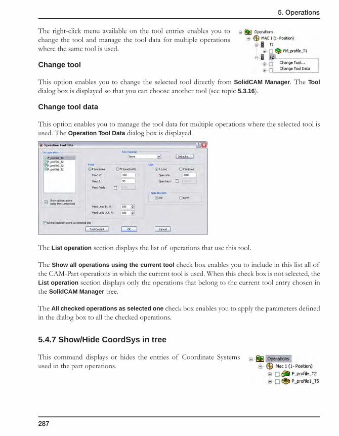
287
5. Operations
The right-click menu available on the tool entries enables you to change the tool and manage the tool data for multiple operations where the same tool is used.
Change tool
This option enables you to change the selected tool directly from SolidCAM Manager. The Tool dialog box is displayed so that you can choose another tool (see topic 5.3.16).
Change tool data
This option enables you to manage the tool data for multiple operations where the selected tool is used. The Operation Tool Data dialog box is displayed.
The List operation section displays the list of operations that use this tool.
The Show all operations using the current tool check box enables you to include in this list all of the CAM-Part operations in which the current tool is used. When this check box is not selected, the List operation section displays only the operations that belong to the current tool entry chosen in the SolidCAM Manager tree.
The All checked operations as selected one check box enables you to apply the parameters defined in the dialog box to all the checked operations.
5.4.7 Show/Hide CoordSys in tree
This command displays or hides the entries of Coordinate Systems used in the part operations.
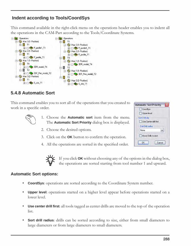
288
Indent according to Tools/CoordSys
This command available in the right-click menu on the operations header enables you to indent all the operations in the CAM-Part according to the Tools/Coordinate Systems.
5.4.8 Automatic Sort
This command enables you to sort all of the operations that you created to work in a specific order.
1. Choose the Automatic sort item from the menu. The Automatic Sort Priority dialog box is displayed.
2. Choose the desired options.
3. Click on the OK button to confirm the operation.
4. All the operations are sorted in the specified order.
If you click OK without choosing any of the options in the dialog box, the operations are sorted starting from tool number 1 and upward.
Automatic Sort options:
• CoordSys: operations are sorted according to the Coordinate System number.
• Upper level: operations started on a higher level appear before operations started on a lower level.
• Use center drill first: all tools tagged as center drills are moved to the top of the operation list.
• Sort drill radius: drills can be sorted according to size, either from small diameters to large diameters or from large diameters to small diameters.

289
5. Operations
• Move drills to end: this option moves all drills not tagged as center drills to the end of the operation list.
The following is the order of precedence if more than one option is chosen.
1. CoordSys
2. Upper level
3. Use Center drill first
4. Sort Drill radius
5. Move Drills to end
Undo Sort
This option returns the automatic sort to the original order.

290
5.5 Operation Transformations
When you transform an operation or a group of operations, commands such as move, copy, translate and rotate insert the corresponding G-function and cycle into the GCode file. You can check the defined transformation during the tool path simulation.
1. In SolidCAM Manager, right-click on the entry of the operation you need to transform.
2. Choose the Transform option from the menu.
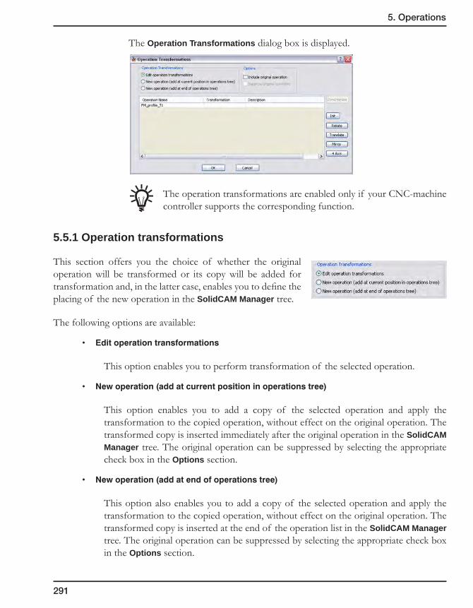
291
5. Operations
The Operation Transformations dialog box is displayed.
The operation transformations are enabled only if your CNC-machine controller supports the corresponding function.
5.5.1 Operation transformations
This section offers you the choice of whether the original operation will be transformed or its copy will be added for transformation and, in the latter case, enables you to define the placing of the new operation in the SolidCAM Manager tree.
The following options are available:
• Editoperationtransformations
This option enables you to perform transformation of the selected operation.
• Newoperation(addatcurrentpositioninoperationstree)
This option enables you to add a copy of the selected operation and apply the transformation to the copied operation, without effect on the original operation. The transformed copy is inserted immediately after the original operation in the SolidCAM Manager tree. The original operation can be suppressed by selecting the appropriate check box in the Options section.
• Newoperation(addatendofoperationstree)
This option also enables you to add a copy of the selected operation and apply the transformation to the copied operation, without effect on the original operation. The transformed copy is inserted at the end of the operation list in the SolidCAM Manager tree. The original operation can be suppressed by selecting the appropriate check box in the Options section.

292
5.5.2 Options
This section contains two check boxes that enable you to manage the original operation:
• Includeoriginaloperation
When this check box is selected, the original operation is included in the transforming action.
• Suppressoriginaloperation
When this check box is selected, the original operation is suppressed, and the transformation is applied only for the operation copy.
This check box is available only when a new operation is added for transformation.
5.5.3 Transformations table
The transformations table lists the details of the defined transformation.
• Operationname
This column displays the list of operations to be transformed. In case of adding a new operation, the operation copy receives the Transform_ prefix with the sequential number of transformation. When an additional transformation action is defined on the existing transformation, the Transform_ prefix is added with the next sequential number, and the names of the previously transformed operations move under the new transformation.
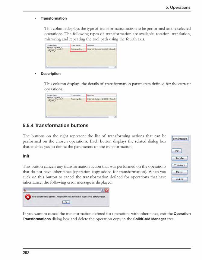
293
5. Operations
• Transformation
This column displays the type of transformation action to be performed on the selected operations. The following types of transformation are available: rotation, translation, mirroring and repeating the tool path using the fourth axis.
• Description
This column displays the details of transformation parameters defined for the current operations.
5.5.4 Transformation buttons
The buttons on the right represent the list of transforming actions that can be performed on the chosen operations. Each button displays the related dialog box that enables you to define the parameters of the transformation.
Init
This button cancels any transformation action that was performed on the operations that do not have inheritance (operation copy added for transformation). When you click on this button to cancel the transformation defined for operations that have inheritance, the following error message is displayed:
If you want to cancel the transformation defined for operations with inheritance, exit the Operation Transformations dialog box and delete the operation copy in the SolidCAM Manager tree.

294
Rotate
This button enables you to define the tool path rotation around the Z-axis of the CoordSys origin or around the Z-axis passing through a defined point. The rotation can be performed using two options:
• Delta
Several rotations are performed from a start angle with a uniform delta angle. The Rotate Delta dialog box is displayed.
1. Enter the Number of Rotations.
2. Start angle – enter the start angle (+/-) relative to the positive X-axis.
3. Delta angle – enter the delta value (+/-) between two rotation steps.
4. Confirm with the OK button.
• List
This option copies the operation tool path to a list of angle locations defined by their angle relative to the positive X-axis. The Rotate list dialog box is displayed.
1. Enter the value of the angle and the number of rotations.
2. Click on the Add button to add the angle to the list of angles.
3. Confirm with the OK button.
To edit an angle value in the list, click on the corresponding entry in the Value column and enter the new value.
To delete an entry from the list, select it and click on the Delete Selected button.
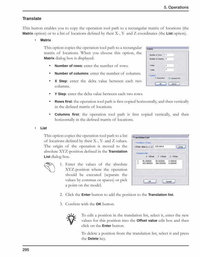
295
5. Operations
Translate
This button enables you to copy the operation tool path to a rectangular matrix of locations (the Matrix option) or to a list of locations defined by their X-, Y- and Z-coordinates (the List option).
• Matrix
This option copies the operation tool path to a rectangular matrix of locations. When you choose this option, the Matrix dialog box is displayed.
• Number of rows: enter the number of rows.
• Number of columns: enter the number of columns.
• X Step: enter the delta value between each two columns.
• Y Step: enter the delta value between each two rows.
• Rows first: the operation tool path is first copied horizontally, and then vertically in the defined matrix of locations.
• Columns first: the operation tool path is first copied vertically, and then horizontally in the defined matrix of locations.
• List
This option copies the operation tool path to a list of locations defined by their X-, Y- and Z-values. The origin of the operation is moved to the absolute XYZ-position defined in the Translation List dialog box.
1. Enter the values of the absolute XYZ-position where the operation should be executed (separate the values by commas or spaces) or pick a point on the model.
2. Click the Enter button to add the position to the Translation list.
3. Confirm with the OK button.
To edit a position in the translation list, select it, enter the new values for this position into the Offset value edit box and then click on the Enter button.
To delete a position from the translation list, select it and press the Delete key.
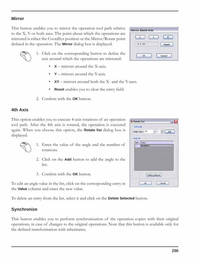
296
Mirror
This button enables you to mirror the operation tool path relative to the X, Y or both axes. The point about which the operations are mirrored is either the CoordSys position or the Mirror/Rotate point defined in the operation. The Mirror dialog box is displayed.
1. Click on the corresponding button to define the axis around which the operations are mirrored:
• X – mirrors around the X-axis.
• Y – mirrors around the Y-axis.
• XY – mirrors around both the X- and the Y-axes.
• Reset enables you to clear the entry field.
2. Confirm with the OK button.
4th Axis
This option enables you to execute 4-axis rotations of an operation tool path. After the 4th axis is rotated, the operation is executed again. When you choose this option, the Rotate list dialog box is displayed.
1. Enter the value of the angle and the number of rotations.
2. Click on the Add button to add the angle to the list.
3. Confirm with the OK button.
To edit an angle value in the list, click on the corresponding entry in the Value column and enter the new value.
To delete an entry from the list, select it and click on the Delete Selected button.
Synchronize
This button enables you to perform synchronization of the operation copies with their original operations, in case of changes to the original operations. Note that this button is available only for the defined transformation with inheritance.

297
5. Operations
When you click on this button, the Synchronization of operations technology dialog box is displayed.
• Synchronizethetechnologyofthisoperationwithitsoriginaloperation
When the original operation has been edited, this option enables you to synchronize the operation copy with the performed changes.
• Synchronizethetechnologyofalloperationswithoriginaloperation
When transformation is defined for multiple operations and the original operations have been edited, this option enables you to synchronize the operation copies with the changes made in the original operations.

298
5.6 Fixture
SolidCAM enables you to define the Part Fixtures such as clamps, vises, jig plates, etc.
This feature enables you to get a more realistic picture during the simulation and check possible collisions between the cutting tools and fixtures.
1. Right-click on an operation entry in the SolidCAM Manager tree and choose Define Fixture.
2. The Fixture dialog box is displayed. This dialog box enables you to define the fixture geometry.

299
5. Operations
5.6.1 Fixture dialog box
Define 3D Model
This button enables you to select the 3D model for the fixture. The 3D Geometry dialog box is displayed.
Show on Model
With this button, you can highlight the selected fixture model in the SolidWorks window.
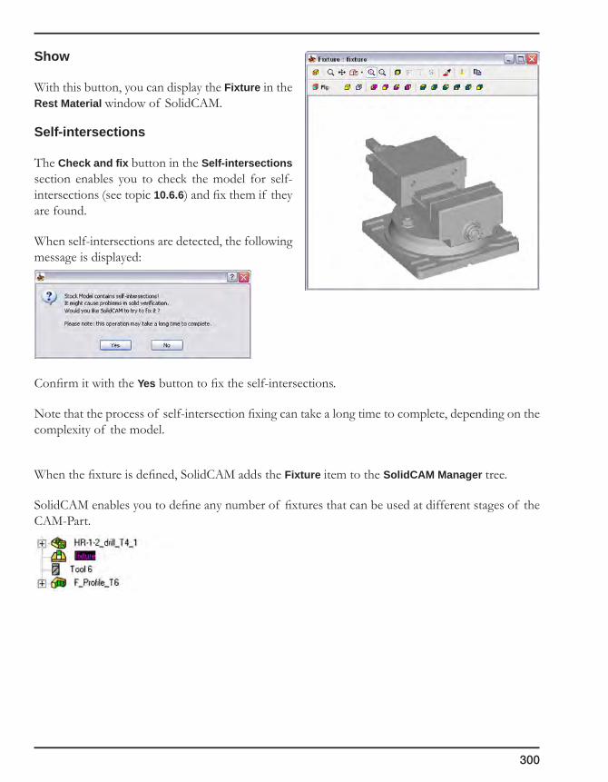
300
Show
With this button, you can display the Fixture in the Rest Material window of SolidCAM.
Self-intersections
The Check and fix button in the Self-intersections section enables you to check the model for self-intersections (see topic 10.6.6) and fix them if they are found.
When self-intersections are detected, the following message is displayed:
Confirm it with the Yes button to fix the self-intersections.
Note that the process of self-intersection fixing can take a long time to complete, depending on the complexity of the model.
When the fixture is defined, SolidCAM adds the Fixture item to the SolidCAM Manager tree.
SolidCAM enables you to define any number of fixtures that can be used at different stages of the CAM-Part.

2.5D MillingSolidCAM enables you to perform a number of standard 2.5D operations like profile, pocket, slot machining, etc. These operations can be performed using 2D sketches as well as solid models.
Full tool path control and powerful algorithms ensure that your manufacturing will be performed in accordance with your plans.
Profile Operation
Pocket Operation
Drilling Operation
Slot Operation
Translated Surface Operation
6
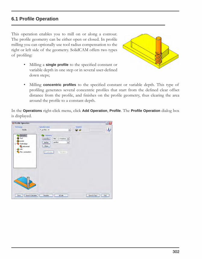
302
6.1 Profile Operation
This operation enables you to mill on or along a contour. The profile geometry can be either open or closed. In profile milling you can optionally use tool radius compensation to the right or left side of the geometry. SolidCAM offers two types of profiling:
• Milling a single profile to the specified constant or variable depth in one step or in several user-defined down steps;
• Milling concentric profiles to the specified constant or variable depth. This type of profiling generates several concentric profiles that start from the defined clear offset distance from the profile, and finishes on the profile geometry, thus clearing the area around the profile to a constant depth.
In the Operations right-click menu, click Add Operation, Profile. The Profile Operation dialog box is displayed.
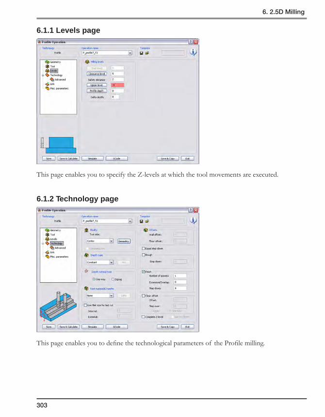
303
6. 2.5D Milling
6.1.1 Levels page
This page enables you to specify the Z-levels at which the tool movements are executed.
6.1.2 Technology page
This page enables you to define the technological parameters of the Profile milling.
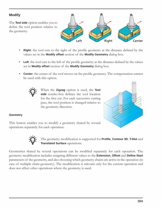
304
Modify
The Tool side option enables you to define the tool position relative to the geometry.
• Right: the tool cuts to the right of the profile geometry at the distance defined by the values set in the Modify offset section of the Modify Geometry dialog box.
• Left: the tool cuts to the left of the profile geometry at the distance defined by the values set in Modify offset section of the Modify Geometry dialog box.
• Center: the center of the tool moves on the profile geometry. The compensation cannot be used with this option.
When the Zigzag option is used, the Tool side combo-box defines the tool location for the first cut. For each successive cutting pass, the tool position is changed relative to the geometry direction.
Geometry
This button enables you to modify a geometry shared by several operations separately for each operation.
The geometry modification is supported for Profile, Contour 3D, T-Slot and Translated Surface operations.
Geometries shared by several operations can be modified separately for each operation. The geometry modification includes assigning different values to the Extension, Offset and Define Start parameters of the geometry, and also choosing which geometry chains are active in the operation (in case of multiple chain geometry). The modification is relevant only for the current operation and does not affect other operations where the geometry is used.
Left Right Center

305
6. 2.5D Milling
The Modify Geometry dialog box enables you to perform the geometry modification for the current operation.
• Tool side
This option enables you to define the position of the tool relative to the geometry.
• Chains
This section displays the list of all geometry chains participating in the current geometry. The check box located near each chain name in the list enables you to include/exclude the chain from the geometry of the current operation.
The right-click menu available on the elements of the list enables you to perform the following actions:
• The Check All command enables you to check all the chains.
• The Uncheck All command enables you to uncheck all the chains.
• The Invert Check States command enables you to reverse the state of the check boxes.
• The Reverse command enables you to reverse the direction of the chain.
• The Reverse All command enables you to reverse the direction of all chains.

306
• Start/EndExtension
This section enables you to define the extension for the selected chain. The Start and End parameters define the start and end extension lengths. The extension is performed tangentially to the chain entities at the start and end points of the geometry chain. The start and end elements are determined according to the chain direction.
When a negative value is defined, SolidCAM shortens the chain by a distance measured along the chain elements and specified by the Start and End parameters. These parameters can be defined either by entering the values or by picking on the model (when the cursor is placed in the edit box).
The Apply to all button enables you to apply the extension defined for the selected chain to all chains of the geometry.
• Modify offset
This section enables you to define the offset for the selected chain. Machining is performed at the specified offset.
Machining Geometry
Modify offset
Geometry chain
Start extension
End extension

307
6. 2.5D Milling
SolidCAM enables you to define the Modify offset parameter by entering the value or by picking on the model (when the cursor is placed in the edit box).
The Apply to all button enables you to apply the Modify offset value defined for the selected chain for all the chains of the geometry.
The direction of the Modify offset parameter for open contours is defined according to the chain direction. In case of a positive value, the offset is defined to the right side of the chain (according to the chosen chain direction). In case of a negative value, the offset is defined to the left side of the chain (according to the chosen chain direction).
For closed contours, a positive Modify offset value defines the offset to the outside of the geometry; a negative Modify offset value defines the offset to the inside of the geometry
The Take 1/2 from selected offset option enables you to offset the chain by half of the defined offset value.
Geometry chain
Modify offset
Modified chain
Positive offset
Negative offset
Geometry chain
Positive offset
Negative offset
Geometry chain

308
In the part shown below the central pads should be machined with a single straight cutting pass located in the middle of the pad. After defining the geometry at the edge of the pad, the geometry is offset using the picked position at the opposite edge and the Take 1/2 from selected offset option.
• Start position
When the Default option is chosen, the start position is calculated automatically using the SolidCAM internal algorithm.
When the Shift option is chosen, you to define the shifting of the start position for closed chains. The shifting of the start point is defined as a percentage of the chain length. You can define the start position shifting either by entering the Shift value or by picking the position on the model. For open chains, this section is disabled.
The Apply to all button enables you to apply the Shift value defined for the selected chain to all closed chains of the current geometry.
The Auto next button enables you to define the start points successively for all closed chains by picking the positions on the model. When this mode is activated, the first closed chain is highlighted, enabling you to pick the start position for it. When the position is picked, SolidCAM switches to the next closed chain and so on. The Resume button enables you to finish the automatic definition of the next start positions.
The Set default button enables you to return the start position of the current chain to its initial state. When the Apply to all check box is activated, the Set default button returns the start positions of all chains to their initial state.
Modifiedgeometry
Geometry
Pickedoffset position
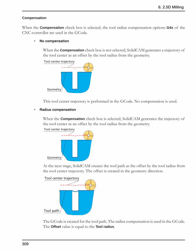
309
6. 2.5D Milling
Compensation
When the Compensation check box is selected, the tool radius compensation options G4x of the CNC-controller are used in the GCode.
• Nocompensation
When the Compensation check box is not selected, SolidCAM generates a trajectory of the tool center as an offset by the tool radius from the geometry.
This tool center trajectory is performed in the GCode. No compensation is used.
• Radiuscompensation
When the Compensation check box is selected, SolidCAM generates the trajectory of the tool center as an offset by the tool radius from the geometry.
At the next stage, SolidCAM creates the tool path as the offset by the tool radius from the tool center trajectory. The offset is created in the geometry direction.
The GCode is created for the tool path. The radius compensation is used in the GCode. The Offset value is equal to the Tool radius.
Tool center trajectory
Geometry
Tool center trajectory
Geometry
Tool center trajectory
Tool path

310
• ZeroCompensation
SolidCAM calculates the trajectory of the tool center as the offset from the geometry.
This trajectory is used in the GCode. The radius compensation is used. The Offset value is equal to 0.
• Settings
SolidCAM enables you to define the type of compensation used by the specific variable in the MAC file.
Comp_by_zero_tool = N – the Radius compensation is used.
Comp_by_zero_tool = Y – the Zero compensation is used.
When the compensation is used for the tool path linked using the Zigzag option, SolidCAM takes into account the machining direction and the changes in the tool position relative to the geometry direction for each successive cut. The different compensation commands are used in the GCode output for even and odd cuts.
Depth type
This option enables you to choose the depth type for the profile.
Constant
SolidCAM generates a tool path with a constant depth as defined in the Milling levels area.
Tool center trajectory
Geometry

311
6. 2.5D Milling
Variable (Define)
You can define a different depth at different profile points.
1. Choose the Define option.
2. Click on the Pick button. The Define depth dialog box is displayed. This dialog box enables you to control the points where the depth changes.
The X,Y,Z dialog box enables you to enter the coordinates of the depth change points.
Switch between the Select and the Unselect mode to define or remove points where the depth changes. The Undo button cancels or restores the last selection.
You can specify a certain chain in the profile geometry using the combo box with the profile number and the Next Profile button.
The Points field contains information about selected depth changing points. You can change the point properties by double-clicking the parameter in this area.
• Profile No. – the Profile geometry chain number.
• Z – the Z-coordinate of the profile depth at the specified point.
• Type – the type of depth change:
Vertical: the depth changes at specified points.
Sloped: the depth changes gradually over the tool path segment.
Select the depth change point on the profile. The Depth dialog box is displayed. In this dialog box, specify the depth and the type of depth change.
Vertical type Sloped type
Depth change points
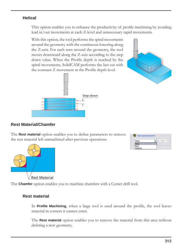
312
Helical
This option enables you to enhance the productivity of profile machining by avoiding lead in/out movements at each Z-level and unnecessary rapid movements.
With this option, the tool performs the spiral movements around the geometry with the continuous lowering along the Z-axis. For each turn around the geometry, the tool moves downward along the Z-axis according to the step down value. When the Profile depth is reached by the spiral movements, SolidCAM performs the last cut with the constant Z movement at the Profile depth level.
Rest Material/Chamfer
The Rest material option enables you to define parameters to remove the rest material left unmachined after previous operations.
The Chamfer option enables you to machine chamfers with a Center drill tool.
Rest material
In Profile Machining, when a large tool is used around the profile, the tool leaves material in corners it cannot enter.
The Rest material option enables you to remove the material from this area without defining a new geometry.
Rest Material
Step down

313
6. 2.5D Milling
The Rest Material dialog box is displayed. You have to define the following parameters:
• Previous tool diameter – the diameter of the rough end mill used in the previous operation. The button enables you to display the Part Tool Table and select the previously used tool so that its diameter appears in the edit box.
• Previous wall offset – the wall offset of the previous operation.
• Extension – the overlap distance that you would like to start and end from the previous larger end mill.
Milling type
• Separate areas
SolidCAM generates a profile tool path to clean areas that the previous tool could not mill.
• Around profile
SolidCAM machines the whole closed profile to mill the rest material.
Rest MaterialExtension

314
Chamfer
This feature in Profile, Pocket and Contour 3D operations enables you to use a drill tool as well as a taper tool to add a chamfer to the edge of a part.
In the Tool page of the operation dialog box, click on the Select button. The Part Tool Table dialog box is displayed. Choose a drill tool for the chamfering.
In the Levels page of the operation dialog box, enter the size of the chamfer edge in the Profile depth field.
In the Technology page of the operation dialog box, choose Chamfer from the Rest Material/Chamfer list and click the Data button.

315
6. 2.5D Milling
In the Chamfer dialog box, enter the following parameters:
• Cuttingdiameter – the starting cutting diameter of the tool;
• Feed – the feed rate you would like the tool to travel.
When the Cutting diameter value is greater than the lower diameter of the taper tool cone, you can move the tool tip outside the chamfer. In such a way, the machining is performed by the conical part of the tool that can avoid the burr formation on the chamfer edge.
If you choose to chamfer a part that has a sharp corner, it is important that the cutting diameter is the same as the last tool used in that geometry so that the chamfer is equal all around.
Fillet size for last cut
This option enables you to add a radius to a sharp corner without the need to change the geometry.
This option is relevant for Profile, Pocket, Slot (Constant depth type) and the 3D Milling (Roughing and Constant-Z finishing) operations.
Cuttingdiameter
Profile depth(Chamfer length)
(Profile depth)Chamfer height
Cutting diameter
∅6
∅6
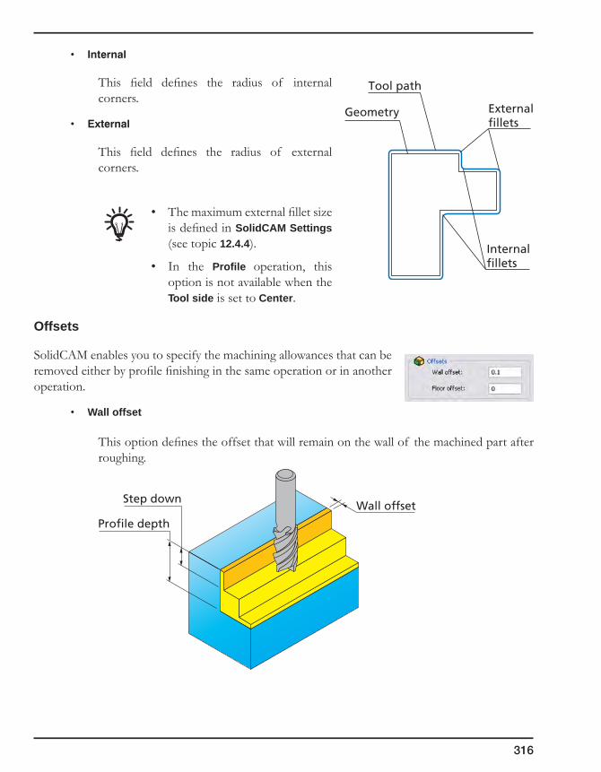
316
• Internal
This field defines the radius of internal corners.
• External
This field defines the radius of external corners.
• The maximum external fillet size is defined in SolidCAM Settings (see topic 12.4.4).
• In the Profile operation, this option is not available when the Tool side is set to Center.
Offsets
SolidCAM enables you to specify the machining allowances that can be removed either by profile finishing in the same operation or in another operation.
• Wall offset
This option defines the offset that will remain on the wall of the machined part after roughing.
Internalfillets
Externalfillets
Geometry
Tool path
Step downWall offset
Profile depth

317
6. 2.5D Milling
• Floor offset
This option defines the offset that will remain on the floor of the machined part after roughing. When the Floor offset value is specified, SolidCAM performs the machining by the Z-levels defined with the Step down parameter. The machining is performed up to the Floor offset.
The Wall offset and Floor offset parameters are available only when the Rough section is activated.
Clear offset
This option generates several concentric profiles with constant depth that start at the defined clear offset distance from the profile and finish at the geometry of the profile, thus clearing the area around the profile.
The Offset option defines the distance from the geometry at which the milling starts. The Offset value must be equal to or greater than the Wall offset value. The tool starts milling the profile at the distance defined by Clear offset and finishes at the distance defined by Wall offset.
The Step over option defines the overlap of adjacent tool passes. It determines the offset between two successive concentric profiles.
Floor offset
Step down
Profile depth
Clear offset
Modify offset
Walloffset
Step over

318
• The Zigzag option enables you to create the tool path for the Clear offset removal containing both climb and conventional movements.
• The One way option enables you to create the tool path for the Clear offset removal containing only climb movements.
Rough
This section enables you to perform the profile rough machining.
Step down
Profile roughing is performed in constant Z passes. The Step down value defines the distance between each two successive Z-levels.
The cutting passes are calculated using the Clear offset strategy with the specified Offset and Step over parameters and taking into account the specified Wall offset and Floor offset parameters.
Clear offsettool path
Profilegeometry
Step down
Upper level
Profile depth
Clear offsettool path
Profilegeometry
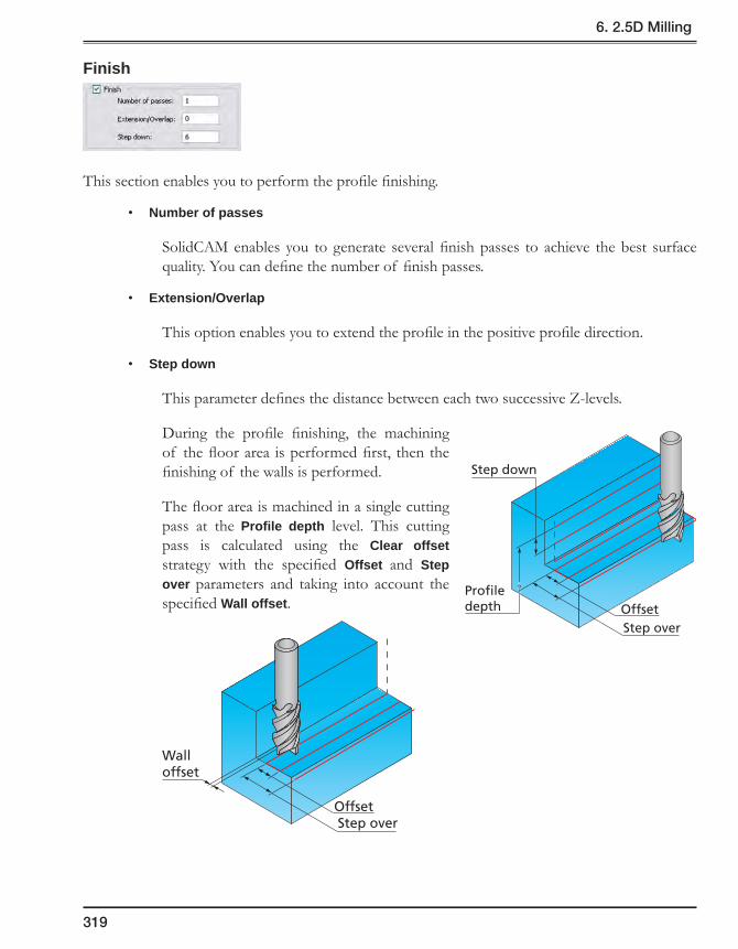
319
6. 2.5D Milling
Finish
This section enables you to perform the profile finishing.
• Number of passes
SolidCAM enables you to generate several finish passes to achieve the best surface quality. You can define the number of finish passes.
• Extension/Overlap
This option enables you to extend the profile in the positive profile direction.
• Step down
This parameter defines the distance between each two successive Z-levels.
During the profile finishing, the machining of the floor area is performed first, then the finishing of the walls is performed.
The floor area is machined in a single cutting pass at the Profile depth level. This cutting pass is calculated using the Clear offset strategy with the specified Offset and Step over parameters and taking into account the specified Wall offset.
Step down
Profiledepth Offset
Step over
Offset
Walloffset
Step over

320
The wall finishing is performed from the Upper level down to the Profile depth in a number of steps defined with the Step down parameter.
Equal step down
Machining of Profiles and Pockets starts from the Upper level and is performed in a number of successive Z-levels till the specified Depth. This option enables you to keep an equal distance between all Z-levels.
When the Equal step down check box is not selected, the distance between each two successive Z-levels is determined by the Step down parameter. If the machining depth is not divisible exactly by the Step down value, the depth of the last cut is smaller than the Step down value.
When the Equal step down check box is selected, an equal distance is kept between all Z-levels. Using this option, you have to specify the Max. Step down parameter instead of the Step down parameter. According to the Depth defined in the operation and modified with the Floor offset and Delta depth parameters, SolidCAM automatically calculates the actual step down to keep an equal distance between all passes, while taking into account the specified Max. Step down so that it is not exceeded.
The Equal step down option is available only for Profile and Pocket operations.
Step down
Profiledepth
Step down
Last cutdepth
Max.Step down
ActualStep down

321
6. 2.5D Milling
Depth cutting type
This section enables you to define the direction of Z-levels machining and the connection between passes.
When the One way option is chosen, the cutting passes are oriented in the same direction and connection between them is performed through the Operation Clearance level. At the end of each pass the tool performs a retreat movement to the Operation Clearance level, a horizontal movement at rapid feed to the start point of the next pass and then descends to the Z-level of the next pass. The same cutting direction (climb or conventional) is kept along the whole tool path.
When the Zigzag option is chosen, the tool path is performed in a zigzag manner, with the tool path direction changing from one pass to the next. The passes located at two successive Z-levels are connected directly from the end of one pass to the beginning of the next pass.
The Zigzag option cannot be used together with the Clear offset technology.
Complete Z-level/Sort by chains
These options enable you to define the order of Z-levels milling in the machining of several profiles in one operation.
These check boxes are not available when the Zigzag option is chosen for Depth cutting type and when the Helical or Define option is chosen for Depth type.
The Sort by chains check box is available only when the Complete Z-level check box is selected and the Clear offset option is used with the One way option.
When the Rough and Finish strategies are used together in the same Profile operation, the Complete Z-Level check box is not available.
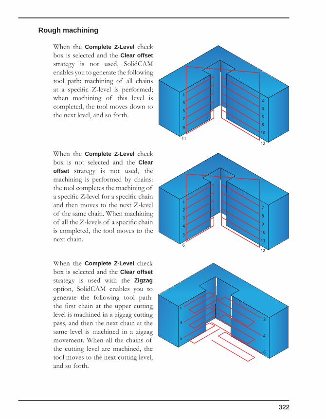
322
Rough machining
When the Complete Z-Level check box is selected and the Clear offset strategy is not used, SolidCAM enables you to generate the following tool path: machining of all chains at a specific Z-level is performed; when machining of this level is completed, the tool moves down to the next level, and so forth.
When the Complete Z-Level check box is not selected and the Clear offset strategy is not used, the machining is performed by chains: the tool completes the machining of a specific Z-level for a specific chain and then moves to the next Z-level of the same chain. When machining of all the Z-levels of a specific chain is completed, the tool moves to the next chain.
When the Complete Z-Level check box is selected and the Clear offset strategy is used with the Zigzag option, SolidCAM enables you to generate the following tool path: the first chain at the upper cutting level is machined in a zigzag cutting pass, and then the next chain at the same level is machined in a zigzag movement. When all the chains of the cutting level are machined, the tool moves to the next cutting level, and so forth.
1
23
45
6
172839410
511
612
12345678
910
1112

323
6. 2.5D Milling
When the Complete Z-Level check box is selected and the Clear offset strategy is used with the One way option, the Sort by chains check box is available. The tool path order depends on the state of this check box.
• When the Sort by chains check box is not selected, SolidCAM enables you to generate the following tool path: the first chain of the first cutting level is machined in several equidistant profiles generated by the Clear offset strategy. When the machining of the chain is finished at the current cutting level, the next chain at the same cutting level is machined. When all the chains of this cutting level are machined, the tool descends to the next cutting level, and so forth.
• When the Sort by chains check box is selected, SolidCAM enables you to generate the following tool path: the first chain of the first cutting level is machined in several equidistant profiles generated by the Clear offset strategy. When the machining of the chain is finished at the current cutting level, SolidCAM performs the machining of the same chain at the next cutting level. When the chain is completely machined at all cutting levels, the next chain is machined in the similar manner.
1
7
13
45
6
1011
12
1617
18
23
89
1415
1
6
7
23
54
89
1011
12
1314
15
1617
18

324
1
2
3
1013
16
1114
17
1215
18
47
58
69
When the Complete Z-Level check box is not selected and the Clear offset strategy is used with the Zigzag option, SolidCAM enables you to generate the following tool path: the first chain of the first cutting level is machined in a zigzag cutting pass, then the tool moves down to the next cutting level. When machining of the current chain is completed at all cutting levels, the next chain is machined in the similar manner.
When the Complete Z-Level check box is not selected and the Clear offset strategy is used with the One way option, SolidCAM enables you to generate the following tool path: the first clear offset cut (farthest from the geometry chain) is machined at the upper cutting level for the first chain. Then the tool descends to the next cutting level and performs the first clear offset cut, and so forth. When the clear offset cut is finished at all Z-levels, the machining of the successive clear offset cuts (closer to the geometry chain) starts from the upper cutting level. When machining of all clear offset cuts is finished for the current chain, the next chain is machined in the similar manner.
1
2
3
4
5
6

325
6. 2.5D Milling
Finish machining
When the Finish check box is selected, the Complete Z-level option is available if the Clear offset strategy is not used.
When the Complete Z-Level check box is selected, the finishing is performed by Z-levels: machining of all chains at a specific Z-level is performed; when machining of this level is completed, the tool moves down to the next level, and so forth.
When the Complete Z-Level check box is not selected, the finishing is performed by chains: the tool completes machining of a specific Z-level for a specific chain and then moves to the next Z-level of the same chain. When machining of all the Z-levels of a specific chain is completed, the tool moves to the next chain.
172839410
511
612
12345678
910
1112
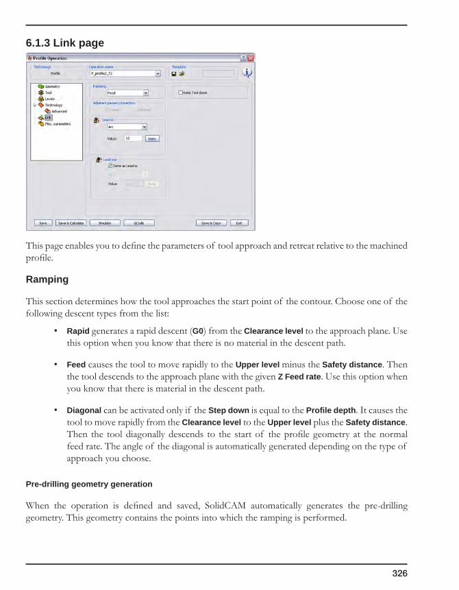
326
6.1.3 Link page
This page enables you to define the parameters of tool approach and retreat relative to the machined profile.
Ramping
This section determines how the tool approaches the start point of the contour. Choose one of the following descent types from the list:
• Rapid generates a rapid descent (G0) from the Clearance level to the approach plane. Use this option when you know that there is no material in the descent path.
• Feed causes the tool to move rapidly to the Upper level minus the Safety distance. Then the tool descends to the approach plane with the given Z Feed rate. Use this option when you know that there is material in the descent path.
• Diagonal can be activated only if the Step down is equal to the Profile depth. It causes the tool to move rapidly from the Clearance level to the Upper level plus the Safety distance. Then the tool diagonally descends to the start of the profile geometry at the normal feed rate. The angle of the diagonal is automatically generated depending on the type of approach you choose.
Pre-drilling geometry generation
When the operation is defined and saved, SolidCAM automatically generates the pre-drilling geometry. This geometry contains the points into which the ramping is performed.

327
6. 2.5D Milling
The pre-drilling geometry can be generated only in the following cases:
• The Normal/Arc/Tangent/Point strategy is used for the Lead in (when the None option is used, the pre-drilling geometry is not generated);
• The Clear offset option is not used;
• The One way option is used for Depth cutting type;
• The Helical mode is not used for Depth type;
• The Wall draft angle option is not used;
• The Rest Material/Chamfer options are not used;
• The Plunging option is not used.
During the generation of the pre-drilling geometry, SolidCAM automatically collects the ramping points of the roughing tool path for all of the chains. For each chain, SolidCAM collects all the ramping points where the vertical penetration into the material is performed. These points are located in the start point of the Lead in movement. Generally, for an open chain, SolidCAM has to generate only one ramping point.
Rampingposition
Lead in
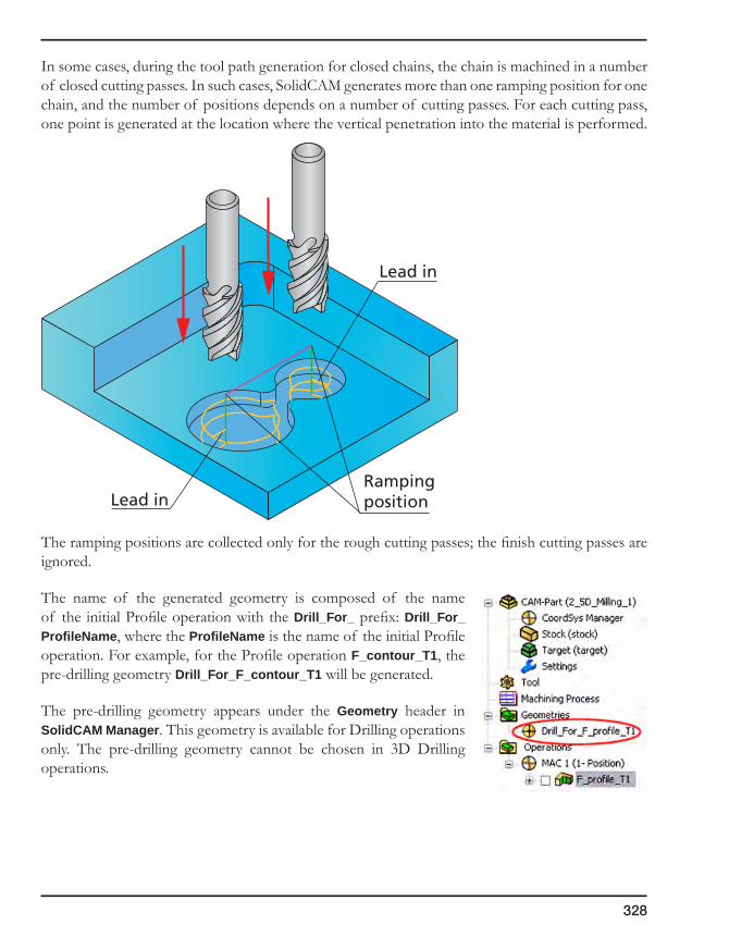
328
In some cases, during the tool path generation for closed chains, the chain is machined in a number of closed cutting passes. In such cases, SolidCAM generates more than one ramping position for one chain, and the number of positions depends on a number of cutting passes. For each cutting pass, one point is generated at the location where the vertical penetration into the material is performed.
The ramping positions are collected only for the rough cutting passes; the finish cutting passes are ignored.
The name of the generated geometry is composed of the name of the initial Profile operation with the Drill_For_ prefix: Drill_For_ProfileName, where the ProfileName is the name of the initial Profile operation. For example, for the Profile operation F_contour_T1, the pre-drilling geometry Drill_For_F_contour_T1 will be generated.
The pre-drilling geometry appears under the Geometry header in SolidCAM Manager. This geometry is available for Drilling operations only. The pre-drilling geometry cannot be chosen in 3D Drilling operations.
RampingpositionLead in
Lead in

329
6. 2.5D Milling
Adjacentpassesconnection
This option enables you to define the connection method for adjacent cutting passes generated using the Clear offset method with the Zigzag option.
The following options are available to define the passes connection:
• Linear
With this option, the tool movement from one cutting pass to the next is performed as a straight line connecting the end point of the first pass with the start point of the next pass.
• Rounded
With this option, the tool movement from one cutting pass to the next is performed as an arc tangential to the adjacent cuttings passes. The arc connects the end point of the first pass to the start point of the next pass.
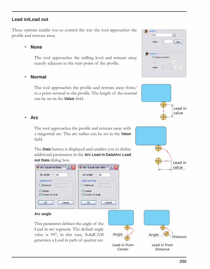
330
Lead in/Lead out
These options enable you to control the way the tool approaches the profile and retreats away.
• None
The tool approaches the milling level and retreats away exactly adjacent to the start point of the profile.
• Normal
The tool approaches the profile and retreats away from/to a point normal to the profile. The length of the normal can be set in the Value field.
• Arc
The tool approaches the profile and retreats away with a tangential arc. The arc radius can be set in the Value field.
The Data button is displayed and enables you to define additional parameters in the Arc Lead in Data/Arc Lead out Data dialog box.
Arc angle
This parameter defines the angle of the Lead in arc segment. The default angle value is 90°; in this case, SolidCAM generates a Lead in path of quarter arc.
Lead invalue
Lead invalue
Angle Angle Distance
Lead in fromDistance
Lead in fromCenter
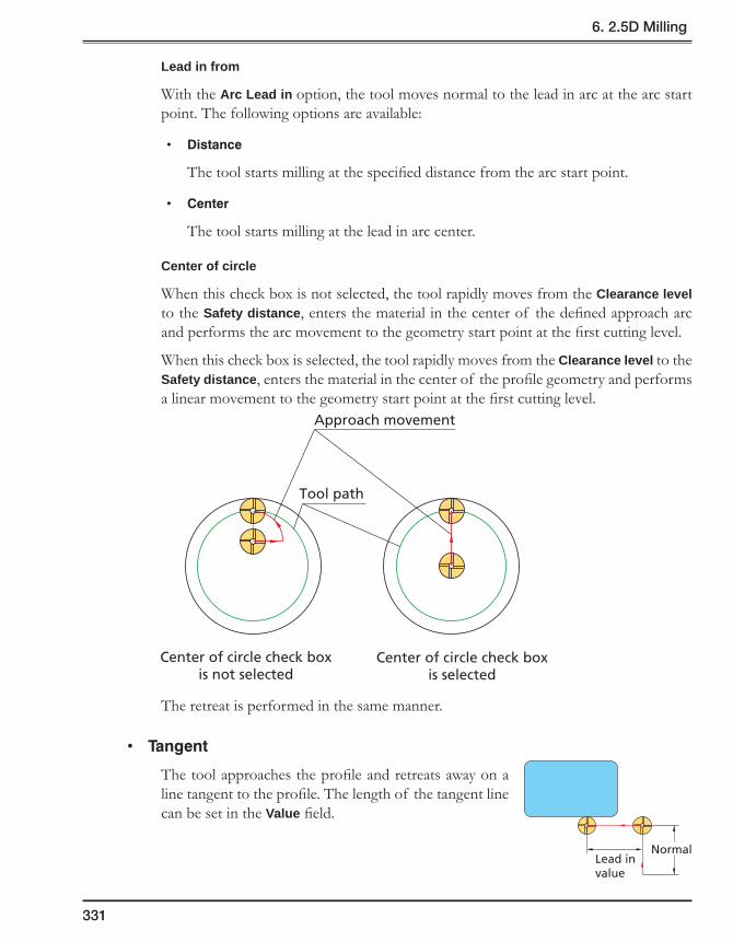
331
6. 2.5D Milling
Lead in from
With the Arc Lead in option, the tool moves normal to the lead in arc at the arc start point. The following options are available:
• Distance
The tool starts milling at the specified distance from the arc start point.
• Center
The tool starts milling at the lead in arc center.
Center of circle
When this check box is not selected, the tool rapidly moves from the Clearance level to the Safety distance, enters the material in the center of the defined approach arc and performs the arc movement to the geometry start point at the first cutting level.
When this check box is selected, the tool rapidly moves from the Clearance level to the Safety distance, enters the material in the center of the profile geometry and performs a linear movement to the geometry start point at the first cutting level.
The retreat is performed in the same manner.
• Tangent
The tool approaches the profile and retreats away on a line tangent to the profile. The length of the tangent line can be set in the Value field.
Lead invalue
Normal
Center of circle check boxis not selected
Tool path
Approach movement
Center of circle check boxis selected
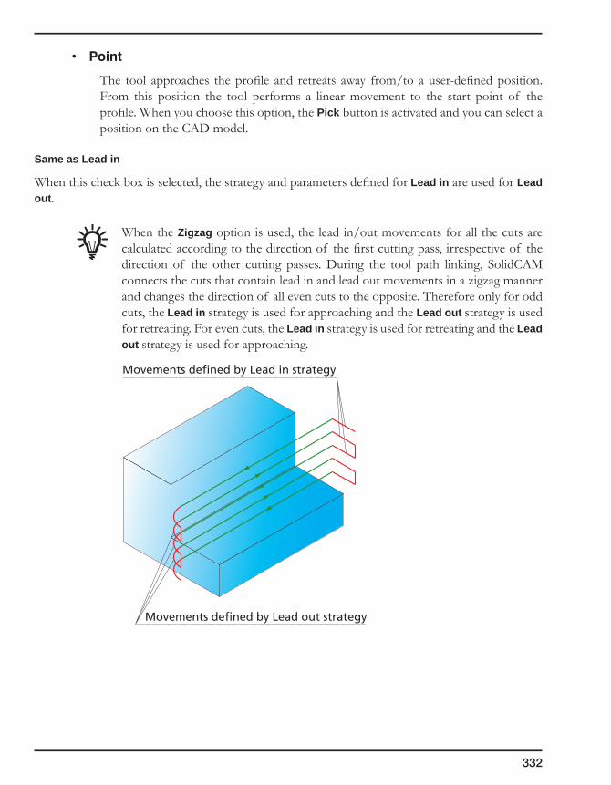
332
• Point
The tool approaches the profile and retreats away from/to a user-defined position. From this position the tool performs a linear movement to the start point of the profile. When you choose this option, the Pick button is activated and you can select a position on the CAD model.
Same as Lead in
When this check box is selected, the strategy and parameters defined for Lead in are used for Lead out.
When the Zigzag option is used, the lead in/out movements for all the cuts are calculated according to the direction of the first cutting pass, irrespective of the direction of the other cutting passes. During the tool path linking, SolidCAM connects the cuts that contain lead in and lead out movements in a zigzag manner and changes the direction of all even cuts to the opposite. Therefore only for odd cuts, the Lead in strategy is used for approaching and the Lead out strategy is used for retreating. For even cuts, the Lead in strategy is used for retreating and the Lead out strategy is used for approaching.
Movements defined by Lead in strategy
Movements defined by Lead out strategy

333
6. 2.5D Milling
Keep tool down
This option enables you to reduce the unnecessary tool movements through the Clearance level.
When the Keep tool down check box is not selected, after the machining of the specific Z-level, the tool retracts up to the Operation Clearance level. At this level the tool horizontally moves to the start position of the next cut and then descends to the next Z-level.
When the Keep tool down check box is selected, after the machining of the specific Z-level, the tool retracts up to the height equal to the Safety distance from the machined cut, then horizontally moves to the start position of the next cut at this level and descends to the next Z-level.
Safetydistance
Clearance level

334
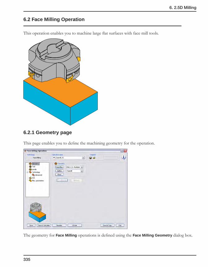
335
6. 2.5D Milling
6.2 Face Milling Operation
This operation enables you to machine large flat surfaces with face mill tools.
6.2.1 Geometry page
This page enables you to define the machining geometry for the operation.
The geometry for Face Milling operations is defined using the Face Milling Geometry dialog box.

336
Name
This edit box enables you to define the geometry name.
Base Geometry
This section enables you to choose the method of the Face Milling geometry definition.
• Model
This option generates a rectangle located at the XY-plane and surrounding the Target model and selects it for the Face Milling geometry. The rectangle chain is displayed in the Chain List section.
• Faces
This option enables you to define the Face Milling geometry by face selection. The Define button and related combo-box enable you either to define a new faces geometry with the Select Faces dialog box or to choose an already defined geometry from the list. When the model faces are selected, SolidCAM generates a number of chains surrounding the selected faces. These chains are displayed in the Chain List section.
Face Milling geometry
Face Milling geometry
Selected faces
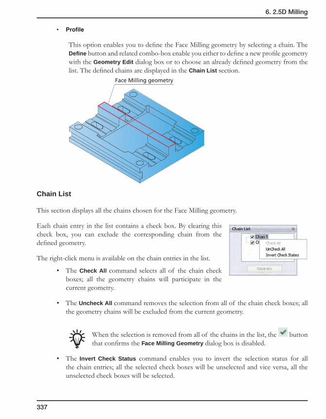
337
6. 2.5D Milling
• Profile
This option enables you to define the Face Milling geometry by selecting a chain. The Define button and related combo-box enable you either to define a new profile geometry with the Geometry Edit dialog box or to choose an already defined geometry from the list. The defined chains are displayed in the Chain List section.
Chain List
This section displays all the chains chosen for the Face Milling geometry.
Each chain entry in the list contains a check box. By clearing this check box, you can exclude the corresponding chain from the defined geometry.
The right-click menu is available on the chain entries in the list.
• The Check All command selects all of the chain check boxes; all the geometry chains will participate in the current geometry.
• The Uncheck All command removes the selection from all of the chain check boxes; all the geometry chains will be excluded from the current geometry.
When the selection is removed from all of the chains in the list, the button that confirms the Face Milling Geometry dialog box is disabled.
• The Invert Check Status command enables you to invert the selection status for all the chain entries; all the selected check boxes will be unselected and vice versa, all the unselected check boxes will be selected.
Face Milling geometry

338
The Merge button enables you to merge all the Face Milling geometry chains into a single chain. The Separate button enables you to divide a merged chain into its initial separate chains.
Modify
This section enables you to offset the chain currently selected in the Chain List section. The Apply to all button enables you to apply the specified offset value to all the chains.
6.2.2 Technology page
This page enables you to define the technological parameters of Face Milling.
Offset
Separate chains Merged chain

339
6. 2.5D Milling
The following technologies are available:
Hatch technology
The machining is performed in a linear pattern.
The Overlap/Min. Overlap section enables you define the tool overlapping between two successive passes. This section is available only for Hatch and Contour strategies.
Equal step over
This option enables you to generate the hatch tool path spaced evenly with the automatically calculated Overlap value, which is nearest to the specified Min. Overlap value but not smaller than this value.
When this check box is not selected, the distance between the last pass and the one before it can be smaller than that between all of the other passes.
When this check box is selected, the evenly spaced hatch tool path is generated. The overlap between two successive passes is not smaller than the specified Min. Overlap value.
This option is available only for the Hatch strategy.
OverlapOverlap
OverlapOverlap

340
The Data button displays the Hatch Data dialog box that enables you to define the parameters of hatching.
Hatch angle
The following options to define the angle of hatching are available:
• Automaticoptionalangle
SolidCAM automatically calculates the optimal angle of hatching to expedite the machining. The tool path always follows the length of the face no matter what angle the machined surface is facing.
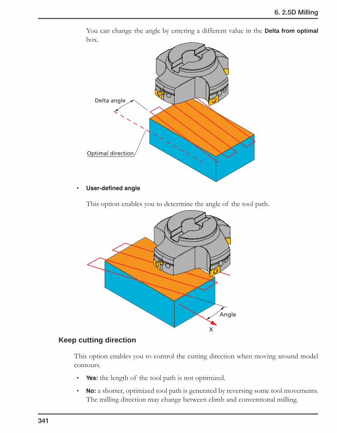
341
6. 2.5D Milling
You can change the angle by entering a different value in the Delta from optimal box.
• User-definedangle
This option enables you to determine the angle of the tool path.
Keep cutting direction
This option enables you to control the cutting direction when moving around model contours.
• Yes:the length of the tool path is not optimized.
• No:a shorter, optimized tool path is generated by reversing some tool movements. The milling direction may change between climb and conventional milling.
Optimal direction
Delta angle
X
Angle

342
Cutting direction
• Oneway
This option enables you to create the tool path with only one-directional movements.
• Zigzag
This option enables you to create the tool path with bi-directional movements.
Extension
During face milling, the tool path is extended over the edges of the machined face. The Extension section enables you to define the extension both along the tool path (the Along section) and across the tool path (the Across section). The extension can be defined either by percentage of the tool diameter (the % of tool diameter option) or by value (the Value option).
Corner
• None
The tool path is formed with sharp corners between one direction and the next.
• Fillet
This option connects each direction with a given radius allowing for a smoother transition between path directions.
Zigzag
One way
Extension alongthe tool path
Extension acrossthe tool path

343
6. 2.5D Milling
Contour technology
The machining is performed in a number of equidistant contours.
The Data button displays the Contour Parameters dialog box.
Start from
• Inside
This option enables you to work in a pocket area starting from the middle of the pocket and cutting towards the outside border of the pocket.
• Outside
This option enables you to work in a pocket area starting from the outside border of the pocket and cutting towards the middle of the pocket.
Corner
• None
The tool path is formed with sharp corners between one direction and the next.
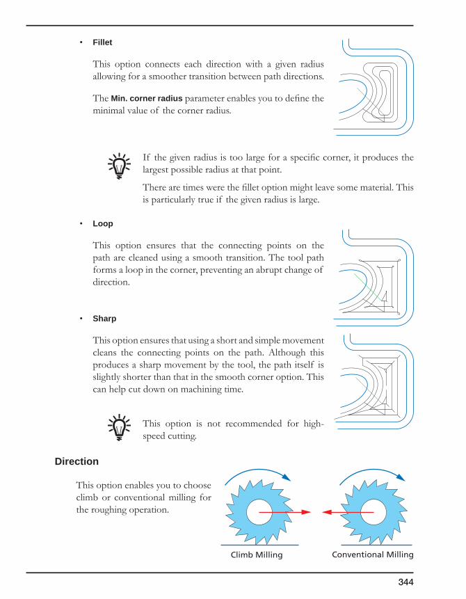
344
• Fillet
This option connects each direction with a given radius allowing for a smoother transition between path directions.
The Min. corner radius parameter enables you to define the minimal value of the corner radius.
If the given radius is too large for a specific corner, it produces the largest possible radius at that point.
There are times were the fillet option might leave some material. This is particularly true if the given radius is large.
• Loop
This option ensures that the connecting points on the path are cleaned using a smooth transition. The tool path forms a loop in the corner, preventing an abrupt change of direction.
• Sharp
This option ensures that using a short and simple movement cleans the connecting points on the path. Although this produces a sharp movement by the tool, the path itself is slightly shorter than that in the smooth corner option. This can help cut down on machining time.
This option is not recommended for high-speed cutting.
Direction
This option enables you to choose climb or conventional milling for the roughing operation.
Conventional MillingClimb Milling
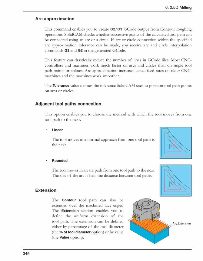
345
6. 2.5D Milling
Arc approximation
This command enables you to create G2/G3 GCode output from Contour roughing operations. SolidCAM checks whether successive points of the calculated tool path can be connected using an arc or a circle. If arc or circle connection within the specified arc approximation tolerance can be made, you receive arc and circle interpolation commands G2 and G3 in the generated GCode.
This feature can drastically reduce the number of lines in GCode files. Most CNC-controllers and machines work much faster on arcs and circles than on single tool path points or splines. Arc approximation increases actual feed rates on older CNC-machines and the machines work smoother.
The Tolerance value defines the tolerance SolidCAM uses to position tool path points on arcs or circles.
Adjacenttoolpathsconnection
This option enables you to choose the method with which the tool moves from one tool path to the next.
• Linear
The tool moves in a normal approach from one tool path to the next.
• Rounded
The tool moves in an arc path from one tool path to the next. The size of the arc is half the distance between tool paths.
Extension
The Contour tool path can also be extended over the machined face edges. The Extension section enables you to define the uniform extension of the tool path. The extension can be defined either by percentage of the tool diameter (the % of tool diameter option) or by value (the Value option).
Extension

346
One pass technology
SolidCAM performs the face milling in one pass. The direction and the location of the pass are calculated automatically according to the face geometry, in order to generate an optimal tool movement with the tool covering the whole geometry.
The Data button displays the One pass data dialog box that enables you to define the machining parameters.
The Extension section enables you to define the tool path extension over the face edges. The extension can be defined either by percentage of the tool diameter (the % of tool diameter option) or by value (the Value option).
Offsets
This section enables you to define the offset that remains on the face floor after the roughing operation (Floor offset).
The Finish check box enables you to remove the remaining offset with the last cut (if the check box is selected) or leave the offset unmachined for further operations (if the check box is not selected).
Depth cutting type
This option enables you to connect cutting passes by vertical zigzag movements. When a cutting pass is machined, the tool moves down to the next cutting level and machines it in the opposite direction. When the machining of all cutting levels is finished for a specific pass, the tool moves to the next cutting pass and machines it in the same manner.
This option is available only for the Hatch and One Pass strategies.
Extension

347
6. 2.5D Milling
The behavior of these options depends on the state of the Cutting direction option defined in the Hatch Data dialog box.
When the Zigzag option is chosen for Cutting direction and the One way option is chosen for Depth cutting type, the tool performs the machining of a cutting pass at a specific Z-level and then moves to the beginning of the next cutting pass located at the successive Z-level and continues the machining in the same direction. The movement to the next cutting pass is performed via the Clearance level.
When the Zigzag option is chosen for Cutting direction and the Zigzag option is chosen for Depth cutting type, the tool performs the machining of a cutting pass at a specific Z-level, then moves directly to the next Z-level and then continues to machine the next cutting pass in the reversed direction.
When the One way option is chosen for Cutting direction and the One way option is chosen for Depth cutting type, the tool machines a cutting pass located at a specific Z-level and then rapidly moves via the Clearance level to the beginning of the next cutting pass at the same Z-level. When the Z-level is machined in such manner, the tool starts the machining of the next Z-level. In this case, SolidCAM preserves the cutting direction (either climb or conventional) for all of the cutting passes.
When the One way option is chosen for Cutting direction and the Zigzag option is chosen for Depth cutting type, the tool performs the machining of all cutting passes at a specific Z-level in the same direction, and then directly moves down to machine the passes at the next Z-level in the opposite direction.
12
3
4
5
6
7
8
9
10
12
3
4
5
6
7
89
10

348
Reverse tool path
The Reverse check box enables you to reverse direction of the tool path. When this check box is selected, the hatch tool path is performed in the opposite direction.
This option is available only for the Hatch and One Pass strategies.
Sort cut order
The Complete Z-level option enables you to define the order of the machining Z-levels, in case more than one face is machined.
For more information, see topic 6.4.3.
Initial tool path Reversed tool path
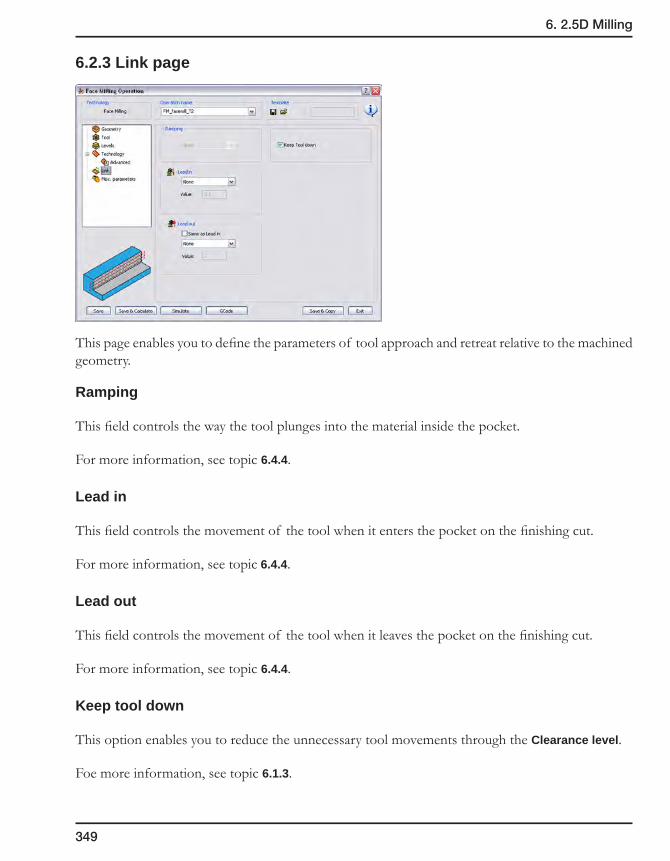
349
6. 2.5D Milling
6.2.3 Link page
This page enables you to define the parameters of tool approach and retreat relative to the machined geometry.
Ramping
This field controls the way the tool plunges into the material inside the pocket.
For more information, see topic 6.4.4.
Lead in
This field controls the movement of the tool when it enters the pocket on the finishing cut.
For more information, see topic 6.4.4.
Lead out
This field controls the movement of the tool when it leaves the pocket on the finishing cut.
For more information, see topic 6.4.4.
Keep tool down
This option enables you to reduce the unnecessary tool movements through the Clearance level.
Foe more information, see topic 6.1.3.

350
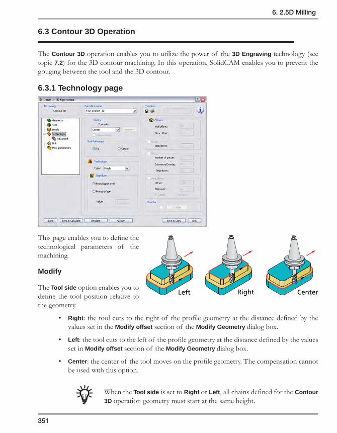
351
6. 2.5D Milling
6.3 Contour 3D Operation
The Contour 3D operation enables you to utilize the power of the 3D Engraving technology (see topic 7.2) for the 3D contour machining. In this operation, SolidCAM enables you to prevent the gouging between the tool and the 3D contour.
6.3.1 Technology page
This page enables you to define the technological parameters of the machining.
Modify
The Tool side option enables you to define the tool position relative to the geometry.
• Right: the tool cuts to the right of the profile geometry at the distance defined by the values set in the Modify offset section of the Modify Geometry dialog box.
• Left: the tool cuts to the left of the profile geometry at the distance defined by the values set in Modify offset section of the Modify Geometry dialog box.
• Center: the center of the tool moves on the profile geometry. The compensation cannot be used with this option.
When the Tool side is set to Right or Left, all chains defined for the Contour 3D operation geometry must start at the same height.
Left Right Center
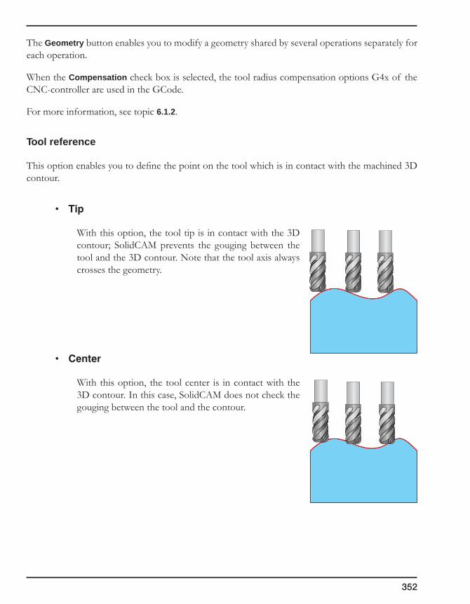
352
The Geometry button enables you to modify a geometry shared by several operations separately for each operation.
When the Compensation check box is selected, the tool radius compensation options G4x of the CNC-controller are used in the GCode.
For more information, see topic 6.1.2.
Tool reference
This option enables you to define the point on the tool which is in contact with the machined 3D contour.
• Tip
With this option, the tool tip is in contact with the 3D contour; SolidCAM prevents the gouging between the tool and the 3D contour. Note that the tool axis always crosses the geometry.
• Center
With this option, the tool center is in contact with the 3D contour. In this case, SolidCAM does not check the gouging between the tool and the contour.
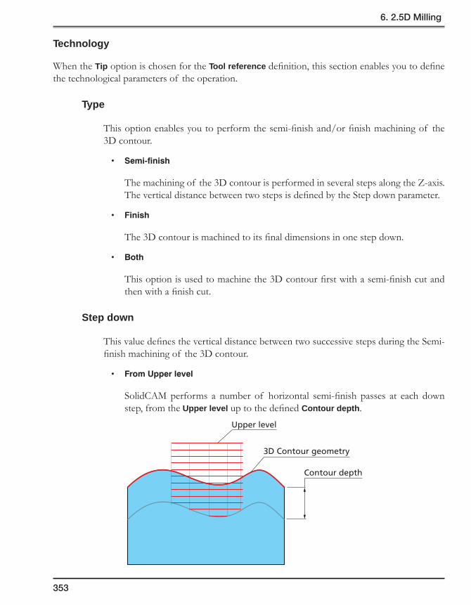
353
6. 2.5D Milling
Technology
When the Tip option is chosen for the Tool reference definition, this section enables you to define the technological parameters of the operation.
Type
This option enables you to perform the semi-finish and/or finish machining of the 3D contour.
• Semi-finish
The machining of the 3D contour is performed in several steps along the Z-axis. The vertical distance between two steps is defined by the Step down parameter.
• Finish
The 3D contour is machined to its final dimensions in one step down.
• Both
This option is used to machine the 3D contour first with a semi-finish cut and then with a finish cut.
Step down
This value defines the vertical distance between two successive steps during the Semi-finish machining of the 3D contour.
• FromUpperlevel
SolidCAM performs a number of horizontal semi-finish passes at each down step, from the Upper level up to the defined Contour depth.
Contour depth
Upper level
3D Contour geometry

354
• Fromsurface
SolidCAM performs a number of 3D semi-finish passes at each step down, from the chosen 3D contour to the defined Contour depth.
The Technology section is not available when the Center option is chosen for the Tool reference definition.
Offsets
SolidCAM enables you to specify the machining allowances that can be removed either by profile finishing in the same operation or in another operation.
For more information, see topic 6.1.2.
Rough
This section enables you to perform the profile rough machining.
For more information, see topic 6.1.2.
Finish
This section enables you to perform the profile finishing.
For more information, see topic 6.1.2.
Clear offset
This section enables you to define the parameters of the Clear offset machining for the roughing and finishing passes.
For more information, see topic 6.1.2.
Contour depth
3D Contour geometry

355
6. 2.5D Milling
Chamfer
This option enables you to machine chamfers with a Center drill tool.
This button is available only when the Right or Left option is chosen for the Tool side definition.
For more information, see topic 6.1.2.
6.3.2 Link page
This page enables you to define the parameters of tool approach and retreat relative to the machined contour.
Lead in/Lead out
These options enable you to control the way the tool approaches and retreats from the contour.
When the Right or Left option is chosen for the Tool side definition, the following Lead in/out options are available:
• None
• Normal
• Arc
• Tangent
• Point
When the Center option is chosen for the Tool side definition, the following Lead in/out options are available:
• None
• Arc
• Tangent
For more information about Lead in/out options, see topic 6.1.3.

356
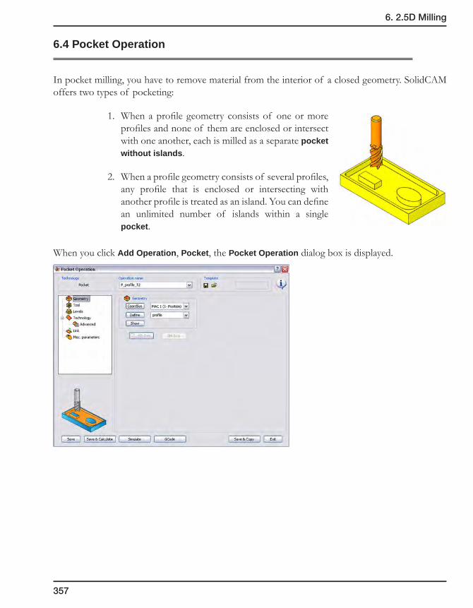
357
6. 2.5D Milling
6.4 Pocket Operation
In pocket milling, you have to remove material from the interior of a closed geometry. SolidCAM offers two types of pocketing:
1. When a profile geometry consists of one or more profiles and none of them are enclosed or intersect with one another, each is milled as a separate pocket without islands.
2. When a profile geometry consists of several profiles, any profile that is enclosed or intersecting with another profile is treated as an island. You can define an unlimited number of islands within a single pocket.
When you click Add Operation, Pocket, the Pocket Operation dialog box is displayed.

358
6.4.1 Geometry page
This page enables you to define the machining geometry for the operation.
The geometry definition is performed using the Geometry Edit dialog box.
Only closed contours are acceptable for the definition of geometry. When you confirm an open chain definition in the Geometry Edit dialog box with the button, the Close Chain dialog box is displayed.
When you confirm this dialog box with the OK button, the chain is closed with a line that connects the start and the end points of the chain. The Mark line as open edge check box enables you to mark the connecting line as open edge to perform open pocket machining.
When you click on the Cancel button, SolidCAM returns to the geometry definition and enables you to close the chain manually by the model element selection.

359
6. 2.5D Milling
6.4.2 Levels page
This page enables you to specify the Z-levels at which the tool movements and the operation are executed.
Step down
SolidCAM uses the constant-Z passes for the Pocket generation. The Step down parameter enables you to define the distance between each two successive Z-levels. Enter the tool’s cutting depth.
Equal step down
Selecting this check box enables you to keep an equal distance between all Z-levels.
When this check box is selected, the Max. Step down parameter appears instead of the Step down parameter.
For more information, see topic 6.1.2.
Step down
Upper level
Pocket depth

360
6.4.3 Technology page
This page enables you to define the technological parameters of the Pocket machining.
Pocket machining technology
Choose the pocket machining technology from the list.
• Hatch mills the pocket in a linear pattern.
• Contour machines the pocket in a round pattern.
• Hatch+Finish mills the pocket in a linear pattern and cleans up the profile on each cutting depth.
• Plunging pattern: the tool moves up and down in a drilling motion, travelling inside the pocket.
Click on the Data button to define additional parameters.
Pocket machiningtechnologies
Hatch
Contour
Hatch+Finish
Plunging pattern
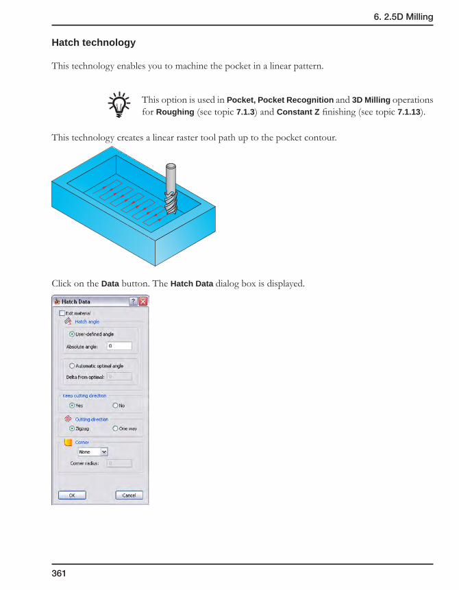
361
6. 2.5D Milling
Hatch technology
This technology enables you to machine the pocket in a linear pattern.
This option is used in Pocket, Pocket Recognition and 3D Milling operations for Roughing (see topic 7.1.3) and Constant Z finishing (see topic 7.1.13).
This technology creates a linear raster tool path up to the pocket contour.
Click on the Data button. The Hatch Data dialog box is displayed.

362
Hatch angle
The following options to define the angle of hatching are available:
• Automatic optional angle
SolidCAM automatically calculates the optimal angle of hatching to expedite the machining. The tool path always follows the length of the pocket no matter what angle the pocket is facing.
You can change the angle by entering a different value in the Delta from optimal box.
• User-defined angle
This option enables you to determine the angle of the tool path.
Keep cutting direction
This option enables you to control the cutting direction when moving around model contours.
• Yes
The length of the tool path is not optimized.
• No
SolidCAM generates a shorter, optimized tool path by reversing some tool movements. The milling direction may change between climb and conventional milling.
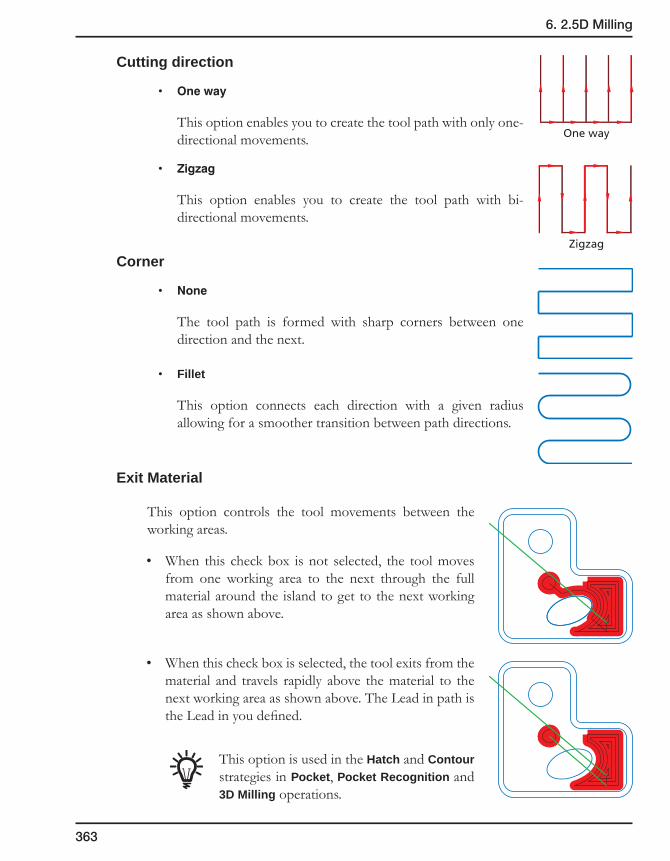
363
6. 2.5D Milling
Cutting direction
• Oneway
This option enables you to create the tool path with only one-directional movements.
• Zigzag
This option enables you to create the tool path with bi-directional movements.
Corner
• None
The tool path is formed with sharp corners between one direction and the next.
• Fillet
This option connects each direction with a given radius allowing for a smoother transition between path directions.
Exit Material
This option controls the tool movements between the working areas.
• When this check box is not selected, the tool moves from one working area to the next through the full material around the island to get to the next working area as shown above.
• When this check box is selected, the tool exits from the material and travels rapidly above the material to the next working area as shown above. The Lead in path is the Lead in you defined.
This option is used in the Hatch and Contour strategies in Pocket, Pocket Recognition and 3D Milling operations.
Zigzag
One way
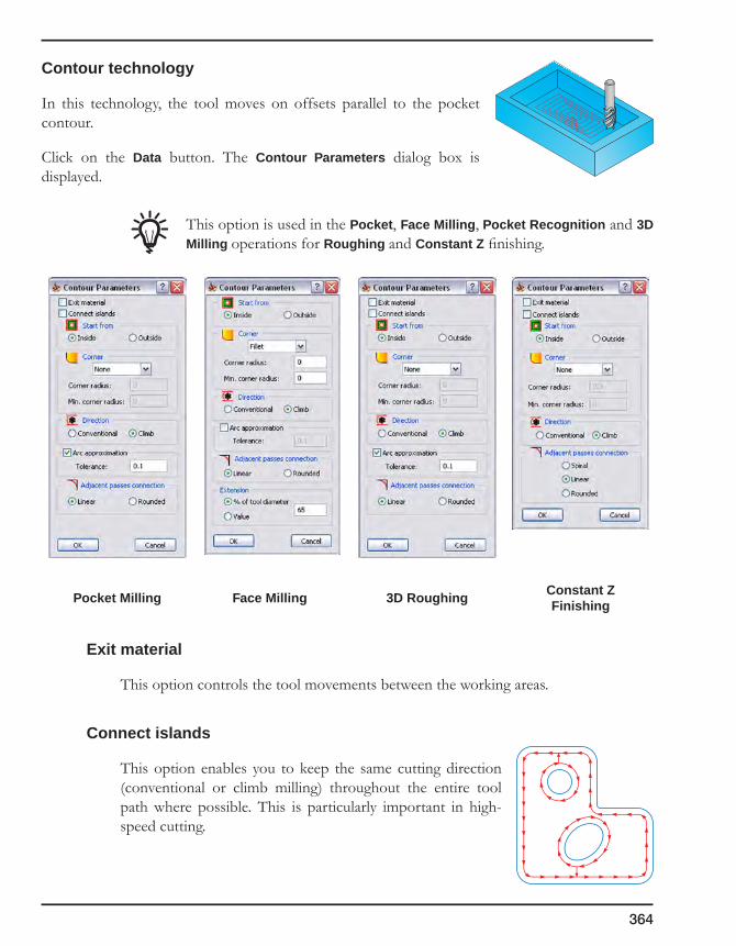
364
Contour technology
In this technology, the tool moves on offsets parallel to the pocket contour.
Click on the Data button. The Contour Parameters dialog box is displayed.
This option is used in the Pocket, Face Milling, Pocket Recognition and 3D Milling operations for Roughing and Constant Z finishing.
Pocket Milling Face Milling 3D Roughing Constant Z Finishing
Exit material
This option controls the tool movements between the working areas.
Connect islands
This option enables you to keep the same cutting direction (conventional or climb milling) throughout the entire tool path where possible. This is particularly important in high-speed cutting.

365
6. 2.5D Milling
Start from
• Inside
This option enables you to work in a pocket area starting from the middle of the pocket and cutting towards the outside border of the pocket.
• Outside
This option enables you to work in a pocket area starting from the outside border of the pocket and cutting towards the middle of the pocket.
Corner
• None
The tool path is formed with sharp corners between one direction and the next.
• Fillet
This option connects each direction with a given radius allowing for a smoother transition between path directions.
The Min. corner radius parameter enables you to define the minimal value of the corner radius.
If the given radius is too large for a specific corner, it produces the largest possible radius at that point.
Some material can be left if the given radius is large.
• Loop
This option ensures that the connecting points on the path are cleaned using a smooth transition. The tool path forms a loop in the corner, preventing an abrupt change of direction.
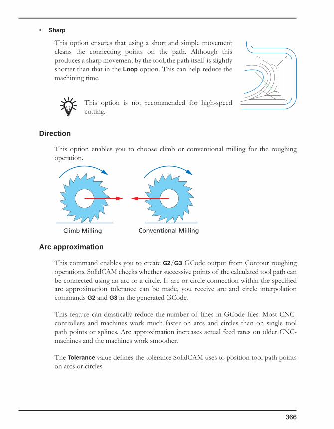
366
• Sharp
This option ensures that using a short and simple movement cleans the connecting points on the path. Although this produces a sharp movement by the tool, the path itself is slightly shorter than that in the Loop option. This can help reduce the machining time.
This option is not recommended for high-speed cutting.
Direction
This option enables you to choose climb or conventional milling for the roughing operation.
Arc approximation
This command enables you to create G2/G3 GCode output from Contour roughing operations. SolidCAM checks whether successive points of the calculated tool path can be connected using an arc or a circle. If arc or circle connection within the specified arc approximation tolerance can be made, you receive arc and circle interpolation commands G2 and G3 in the generated GCode.
This feature can drastically reduce the number of lines in GCode files. Most CNC-controllers and machines work much faster on arcs and circles than on single tool path points or splines. Arc approximation increases actual feed rates on older CNC-machines and the machines work smoother.
The Tolerance value defines the tolerance SolidCAM uses to position tool path points on arcs or circles.
Conventional MillingClimb Milling
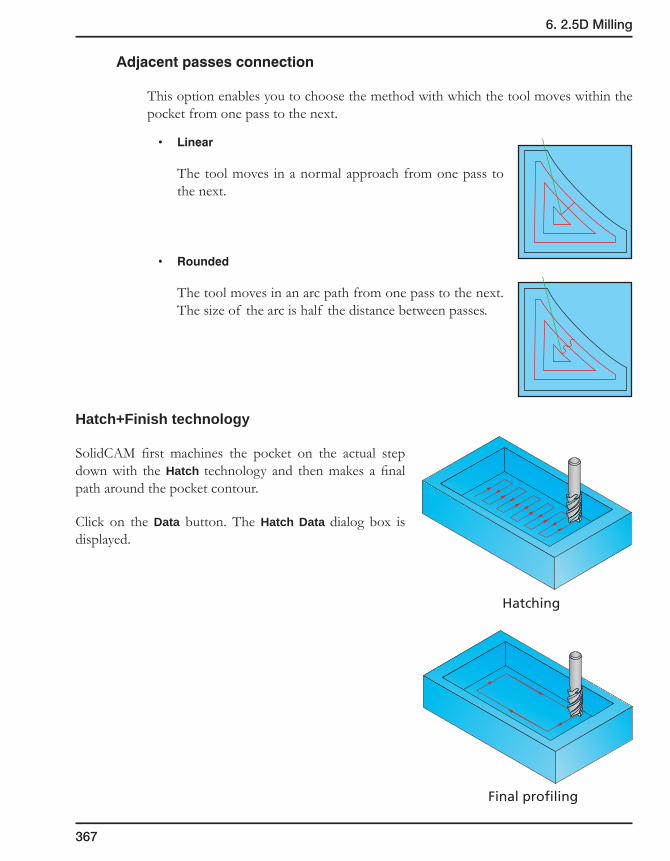
367
6. 2.5D Milling
Adjacentpassesconnection
This option enables you to choose the method with which the tool moves within the pocket from one pass to the next.
• Linear
The tool moves in a normal approach from one pass to the next.
• Rounded
The tool moves in an arc path from one pass to the next. The size of the arc is half the distance between passes.
Hatch+Finish technology
SolidCAM first machines the pocket on the actual step down with the Hatch technology and then makes a final path around the pocket contour.
Click on the Data button. The Hatch Data dialog box is displayed.
Hatching
Final profiling
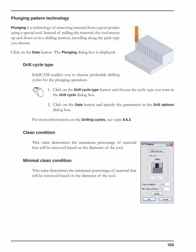
368
Plunging pattern technology
Plunging is a technology of removing material from a given pocket using a special tool. Instead of milling the material, the tool moves up and down as in a drilling motion, travelling along the path type you choose.
Click on the Data button. The Plunging dialog box is displayed.
Drill cycle type
SolidCAM enables you to choose preferable drilling cycles for the plunging operation.
1. Click on the Drill cycle type button and choose the cycle type you want in the Drill cycle dialog box.
2. Click on the Data button and specify the parameters in the Drill options dialog box.
For more information on the Drilling cycles, see topic 6.6.3.
Clean condition
This value determines the maximum percentage of material that will be removed based on the diameter of the tool.
Minimal clean condition
This value determines the minimum percentage of material that will be removed based on the diameter of the tool.

369
6. 2.5D Milling
Feeds
The plunging feeds can be determined by the percentage of the tool and the diameter of the tool being used.
• Full/Center
If the full diameter of the tool is cutting, the feed and spin defined in the appropriate field are used.
In the second field, you can determine a specific working diameter of the tool. If the working diameter from the center of the tool is greater than this value but smaller than the full diameter, the feed and spin rate that was entered in the appropriate field are used.
• Overlap(%)
If none of the above conditions have been met, the feed and spin are determined by the overlap of the tool.
Open pocket machining
This section is enabled only when the pocket geometry contains open edges.
Extension
During the open pocket machining, the tool path is extended beyond the open edges.
The Extension section enables you to define the overlapping between the tool and the open edges; the overlapping can be defined as a percentage of the tool diameter (the % of tool diameter option) or as a value (the Value option). Extension
Open edge
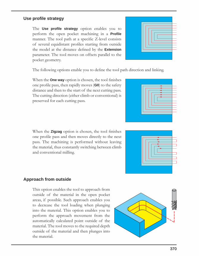
370
Use profile strategy
The Use profile strategy option enables you to perform the open pocket machining in a Profile manner. The tool path at a specific Z-level consists of several equidistant profiles starting from outside the model at the distance defined by the Extension parameter. The tool moves on offsets parallel to the pocket geometry.
The following options enable you to define the tool path direction and linking.
When the One way option is chosen, the tool finishes one profile pass, then rapidly moves (G0) to the safety distance and then to the start of the next cutting pass. The cutting direction (either climb or conventional) is preserved for each cutting pass.
When the Zigzag option is chosen, the tool finishes one profile pass and then moves directly to the next pass. The machining is performed without leaving the material, thus constantly switching between climb and conventional milling.
Approach from outside
This option enables the tool to approach from outside of the material in the open pocket areas, if possible. Such approach enables you to decrease the tool loading when plunging into the material. This option enables you to perform the approach movement from the automatically calculated point outside of the material. The tool moves to the required depth outside of the material and then plunges into the material.

371
6. 2.5D Milling
Descend to cutting level with Rapid
This option enables you to avoid vertical non-machining movements outside of the material performed with the working feed by direct rapid movement down to the cutting level.
When this check box is selected, the tool descends from the Clearance level outside of the material directly to the cutting level (defined with the Step down parameter) using the Rapid feed. Then the horizontal movement into the material is started with the working feed.
When this check box is not selected, the tool descends from the Clearance level down to the Safety distance with the Rapid feed. From the Safety distance, the tool descends down to the cutting level (defined with the Step down parameter) with the defined feed and starts the horizontal cutting movements into the material with the working feed.
The Descend to cutting level with Rapid check box is available only when the Approach from outside check box is selected.
Upper level
Cutting level
Rapid movement
Upper level
Safety distance
Cutting level
Rapid movement
Feed movement
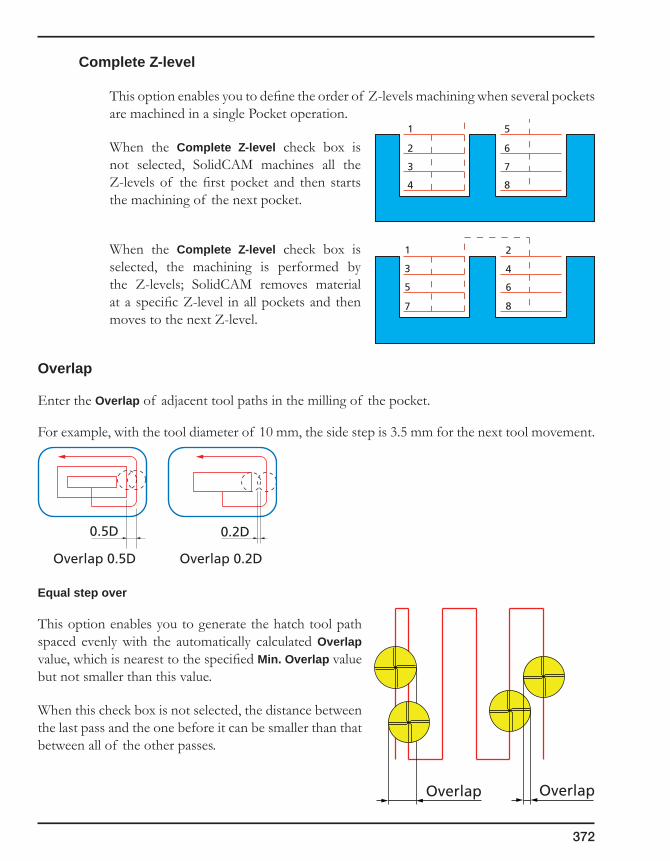
372
Complete Z-level
This option enables you to define the order of Z-levels machining when several pockets are machined in a single Pocket operation.
When the Complete Z-level check box is not selected, SolidCAM machines all the Z-levels of the first pocket and then starts the machining of the next pocket.
When the Complete Z-level check box is selected, the machining is performed by the Z-levels; SolidCAM removes material at a specific Z-level in all pockets and then moves to the next Z-level.
Overlap
Enter the Overlap of adjacent tool paths in the milling of the pocket.
For example, with the tool diameter of 10 mm, the side step is 3.5 mm for the next tool movement.
Equal step over
This option enables you to generate the hatch tool path spaced evenly with the automatically calculated Overlap value, which is nearest to the specified Min. Overlap value but not smaller than this value.
When this check box is not selected, the distance between the last pass and the one before it can be smaller than that between all of the other passes.
1
2
3
4
5
6
7
8
1 2
3 4
5 6
7 8
0.5D
Overlap 0.5D
0.2D
Overlap 0.2D
OverlapOverlap

373
6. 2.5D Milling
When this check box is selected, the evenly spaced hatch tool path is generated. The overlap between two successive passes is not smaller than the specified Min. Overlap value.
Fillet size for last cut
This option enables you to add a radius to a sharp corner without changing the geometry.
For more information on this option, see topic 6.1.2.
Offsets
To perform the rough machining of the pocket, you have to specify the offsets on the pocket geometry that will be removed with the finishing cut.
• Wall offset
Enter the offset that will remain on the pocket wall after the roughing cut.
• Island offset
Enter the offset that will remain on the pocket islands after the roughing cut.
• Floor offset
Enter the offset that will remain on the pocket floor after the roughing cut.
OverlapOverlap

374
Finish
This section enables you to perform the finish machining of the pocket.
The Wall check box enables you to perform finishing of the pocket walls. Only walls and islands are finished on the contour. The pocket depth is reduced by the specified floor offset.
The Floor check box enables you to perform finishing of the pocket floor. The finish cut is executed to remove the floor offset. The specified wall and island offset remain on the pocket contour.
Wall finish
This section field contains two options to control the material removal on the last finishing cut.
• Onoffset
The finish path is executed at an offset equal to the sum of the tool radius and the finish offset from the tool path of the last roughing cut. The result is a uniform cutting depth (side step) on the last cut, since in the pocket corners the tool is not drawn into the material.
• Ongeometry
The last cutting pass is executed exactly on the pocket geometry.
Offset
Offset
Offset
Offset
Offset
R
R
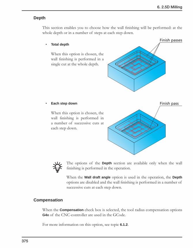
375
6. 2.5D Milling
Depth
This section enables you to choose how the wall finishing will be performed: at the whole depth or in a number of steps at each step down.
• Total depth
When this option is chosen, the wall finishing is performed in a single cut at the whole depth.
• Each step down
When this option is chosen, the wall finishing is performed in a number of successive cuts at each step down.
The options of the Depth section are available only when the wall finishing is performed in the operation.
When the Wall draft angle option is used in the operation, the Depth options are disabled and the wall finishing is performed in a number of successive cuts at each step down.
Compensation
When the Compensation check box is selected, the tool radius compensation options G4x of the CNC-controller are used in the GCode.
For more information on this option, see topic 6.1.2.
Finish passes
Finish pass

376
Rest Material/Chamfer
• The Rest material option enables you to define parameters to remove the rest material left unmachined after the previous operations.
• The Chamfer option enables you to machine chamfers with the Center drill tool.
Rest material
When a large tool is used around the profile in Pocket machining, the tool leaves material in the areas that it cannot enter.
The rest material option enables you to remove the material from this area without defining a new geometry.
The Rest Material dialog box is displayed.
In this dialog box, you have to define the following parameters:
• Previous tool diameter – the diameter of the tool used in the previous operation.
• Previous wall offset – the wall offset used in the previous operation.
• Extension – the overlap distance that you would like to start and end from the previous larger end mill.
Pocketgeometry
Islandgeometry
Rest Material areas
Rest MaterialExtension
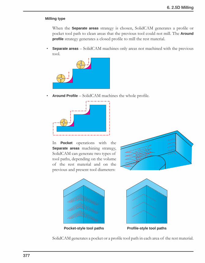
377
6. 2.5D Milling
Milling type
When the Separate areas strategy is chosen, SolidCAM generates a profile or pocket tool path to clean areas that the previous tool could not mill. The Around profile strategy generates a closed profile to mill the rest material.
• Separate areas – SolidCAM machines only areas not machined with the previous tool.
• Around Profile – SolidCAM machines the whole profile.
In Pocket operations with the Separate areas machining strategy, SolidCAM can generate two types of tool paths, depending on the volume of the rest material and on the previous and present tool diameters:
Pocket-style tool paths Profile-style tool paths
SolidCAM generates a pocket or a profile tool path in each area of the rest material.

378
Pocket-style tool path areas can be open or closed depending on the approach possibilities.
The approach to the open pockets can be performed from the machined space in contrast to the closed pockets where the approach from the outside is unavailable.
The strategy for the tool approach to closed pocket areas is defined in the Ramping section (see topic 6.4.4) in the Pocket Operation dialog box.
SolidCAM automatically determines the optimal point for the approach to the open pocket areas.
When the Rest Material option is chosen in the Pocket Operation dialog box, the Lead in option provides you with the following strategies used for the approach to Profile-style tool path areas:
• None
• Normal
• Arc
• Tangent
For more information on the Lead in strategies, see topic 6.4.4.
Open pocket-style tool path area
Open pocket-styletool path area
Profile-style tool path area
Closed pocket-styletool path area
Open pocket-styletool path area
Approach point
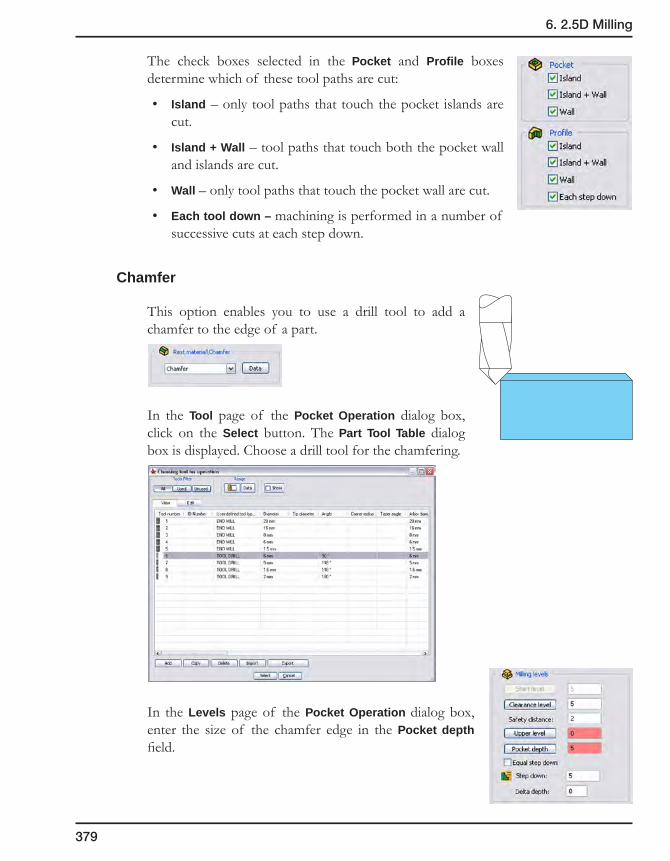
379
6. 2.5D Milling
The check boxes selected in the Pocket and Profile boxes determine which of these tool paths are cut:
• Island – only tool paths that touch the pocket islands are cut.
• Island + Wall – tool paths that touch both the pocket wall and islands are cut.
• Wall – only tool paths that touch the pocket wall are cut.
• Each tool down – machining is performed in a number of successive cuts at each step down.
Chamfer
This option enables you to use a drill tool to add a chamfer to the edge of a part.
In the Tool page of the Pocket Operation dialog box, click on the Select button. The Part Tool Table dialog box is displayed. Choose a drill tool for the chamfering.
In the Levels page of the Pocket Operation dialog box, enter the size of the chamfer edge in the Pocket depth field.
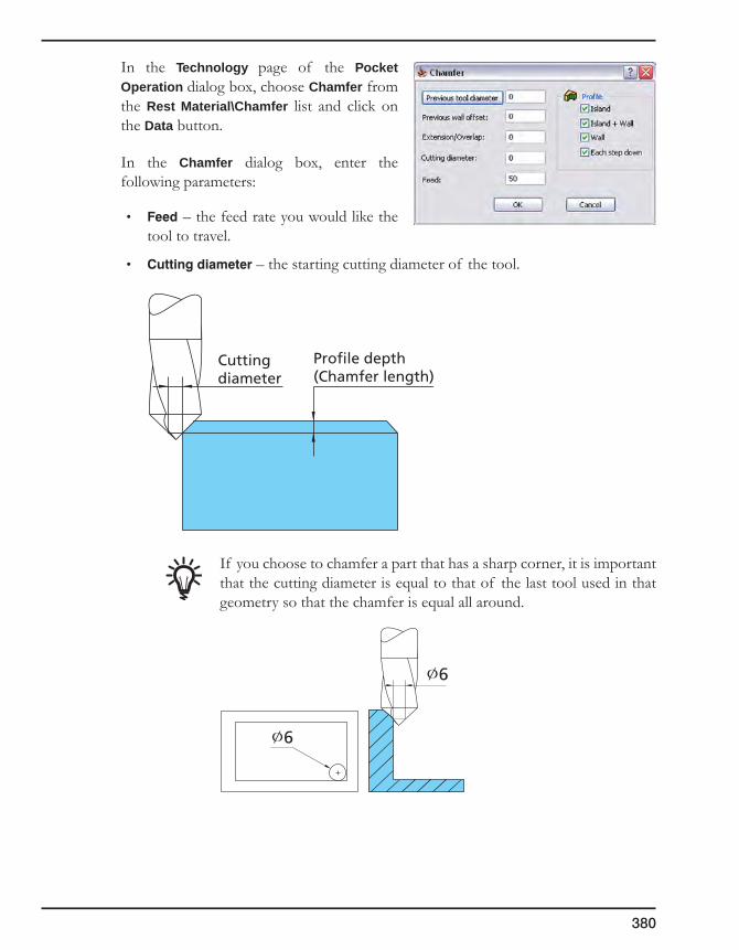
380
In the Technology page of the Pocket Operation dialog box, choose Chamfer from the Rest Material\Chamfer list and click on the Data button.
In the Chamfer dialog box, enter the following parameters:
• Feed – the feed rate you would like the tool to travel.
• Cuttingdiameter – the starting cutting diameter of the tool.
If you choose to chamfer a part that has a sharp corner, it is important that the cutting diameter is equal to that of the last tool used in that geometry so that the chamfer is equal all around.
Cuttingdiameter
Profile depth(Chamfer length)
∅6
∅6

381
6. 2.5D Milling
6.4.4 Link page
This page enables you to define the parameters of tool approach and retreat relative to the machined pocket.
Ramping
This field controls the way the tool plunges into the material inside the pocket. Choose the Ramping mode and set the corresponding parameters.
• None
The tool enters the material vertically at the start point chosen automatically by the SolidCAM pocket algorithm.
• Vertical
The tool enters the material vertically at a user-defined position. From this position, the tool moves to the pocket start point, calculated by the pocket algorithm. The Data button displays the Vertical ramping dialog box that enables you to define the position for the vertical ramping.
Chains
This section displays the list of all geometry chains defined for the operation. All the chain entries are displayed under the Chains header. You can select chain entries in the list.
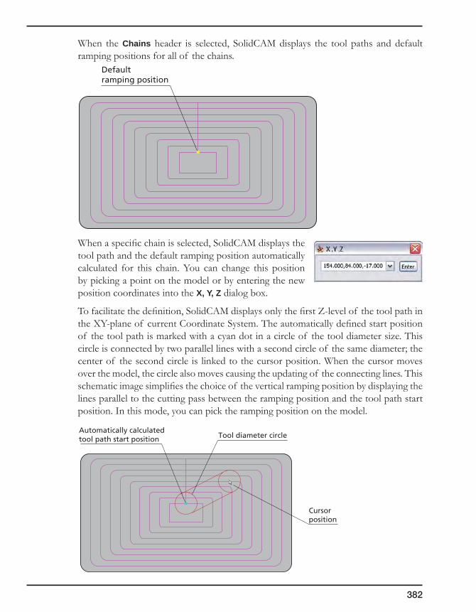
382
When the Chains header is selected, SolidCAM displays the tool paths and default ramping positions for all of the chains.
When a specific chain is selected, SolidCAM displays the tool path and the default ramping position automatically calculated for this chain. You can change this position by picking a point on the model or by entering the new position coordinates into the X, Y, Z dialog box.
To facilitate the definition, SolidCAM displays only the first Z-level of the tool path in the XY-plane of current Coordinate System. The automatically defined start position of the tool path is marked with a cyan dot in a circle of the tool diameter size. This circle is connected by two parallel lines with a second circle of the same diameter; the center of the second circle is linked to the cursor position. When the cursor moves over the model, the circle also moves causing the updating of the connecting lines. This schematic image simplifies the choice of the vertical ramping position by displaying the lines parallel to the cutting pass between the ramping position and the tool path start position. In this mode, you can pick the ramping position on the model.
Automatically calculatedtool path start position
Cursorposition
Tool diameter circle
Defaultramping position
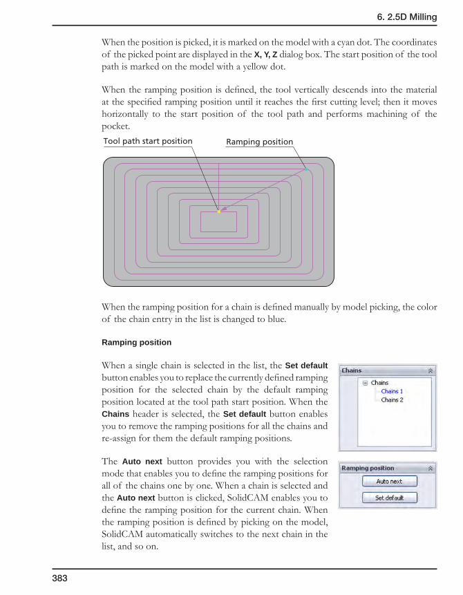
383
6. 2.5D Milling
When the position is picked, it is marked on the model with a cyan dot. The coordinates of the picked point are displayed in the X, Y, Z dialog box. The start position of the tool path is marked on the model with a yellow dot.
When the ramping position is defined, the tool vertically descends into the material at the specified ramping position until it reaches the first cutting level; then it moves horizontally to the start position of the tool path and performs machining of the pocket.
When the ramping position for a chain is defined manually by model picking, the color of the chain entry in the list is changed to blue.
Ramping position
When a single chain is selected in the list, the Set default button enables you to replace the currently defined ramping position for the selected chain by the default ramping position located at the tool path start position. When the Chains header is selected, the Set default button enables you to remove the ramping positions for all the chains and re-assign for them the default ramping positions.
The Auto next button provides you with the selection mode that enables you to define the ramping positions for all of the chains one by one. When a chain is selected and the Auto next button is clicked, SolidCAM enables you to define the ramping position for the current chain. When the ramping position is defined by picking on the model, SolidCAM automatically switches to the next chain in the list, and so on.
Tool path start position Ramping position

384
• Angle
The tool moves to the pocket start point at a specified ramp angle.
The Data button displays the Angle ramping dialog box that enables you to define the ramping position and the related parameters.
Angle ramping parameters
The Angle edit box enables you to define the ramping angle.
Chains
This section displays the list of all geometry chains defined for the operation. All the chain entries are displayed under the Chains header. You can select chain entries in the list.
When the Chains header is selected, SolidCAM displays the tool paths and default ramping positions automatically calculated for all of the chains.
When a chain entry is selected, SolidCAM displays the tool path and the default ramping position automatically calculated for this chain; this position can be changed.
The ramping position is selected in the same manner as for Vertical ramping.
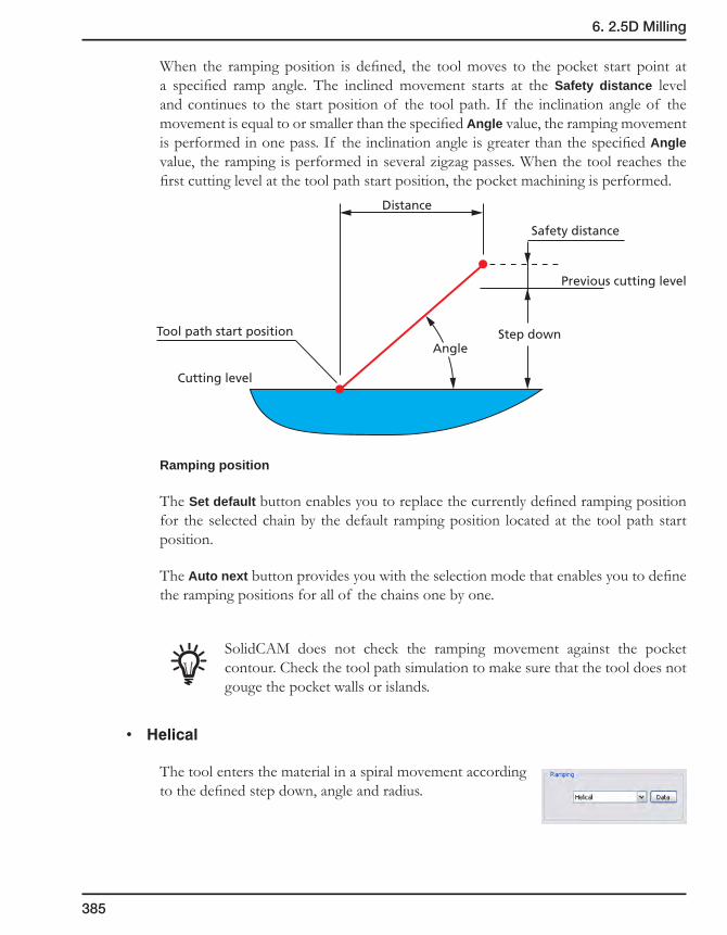
385
6. 2.5D Milling
When the ramping position is defined, the tool moves to the pocket start point at a specified ramp angle. The inclined movement starts at the Safety distance level and continues to the start position of the tool path. If the inclination angle of the movement is equal to or smaller than the specified Angle value, the ramping movement is performed in one pass. If the inclination angle is greater than the specified Angle value, the ramping is performed in several zigzag passes. When the tool reaches the first cutting level at the tool path start position, the pocket machining is performed.
Ramping position
The Set default button enables you to replace the currently defined ramping position for the selected chain by the default ramping position located at the tool path start position.
The Auto next button provides you with the selection mode that enables you to define the ramping positions for all of the chains one by one.
SolidCAM does not check the ramping movement against the pocket contour. Check the tool path simulation to make sure that the tool does not gouge the pocket walls or islands.
• Helical
The tool enters the material in a spiral movement according to the defined step down, angle and radius.
Cutting level
Safety distance
Distance
Step downAngle
Previous cutting level
Tool path start position

386
The Data button displays the Helical ramping dialog box that enables you to define the ramping position and the related parameters.
Helical ramping parameters
The Tool step down parameter defines the distance between each two adjacent turns of the tool helical movement.
The Angle parameter defines the ramping angle.
The Radius parameter defines the radius of the descending helix.
Center cutting
If your tool has center cutting capabilities, select the Center cutting check box. In the Angle field, enter the descent angle that you would like the tool to follow. In the Radius field, enter the radius of the tool path helix.
The working order is as follows:
• The tool descends from the safety distance above the Upper level to the material in a circular motion until the step down is reached using the user-defined radius.
• When the tool reaches the step down depth, it machines all the material at the step down depth.
• When the machining is completed at this depth, the tool goes up to the Clearance level.
• At this stage, the tool repositions itself at the Z safety distance above the previous step down depth and repeats the Helical Lead in to the next working depth.
• This process repeats itself until the final depth has been machined.
If the tool does not have center cutting capabilities, do not select the Center cutting check box. In the Tool step down field, enter the depth of the step down of the tool.
The result of this action is the same as with a center cutting tool except for the following differences:
• The tool descends from the safety distance above the Upper level to the material in a circular motion up to the Tool Step down.
• At this point, the tool clears a circular path. Then it descends to the next Tool step down.
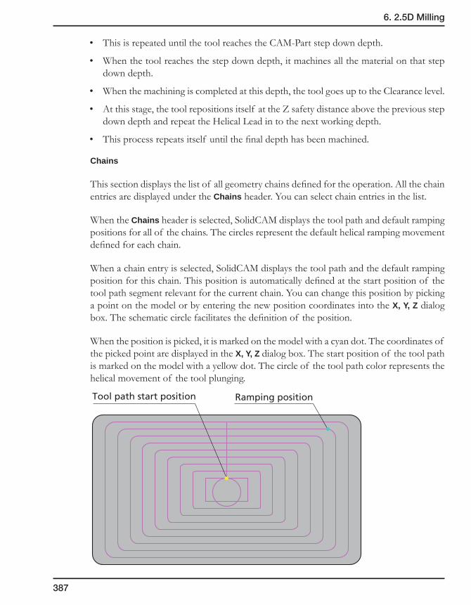
387
6. 2.5D Milling
• This is repeated until the tool reaches the CAM-Part step down depth.
• When the tool reaches the step down depth, it machines all the material on that step down depth.
• When the machining is completed at this depth, the tool goes up to the Clearance level.
• At this stage, the tool repositions itself at the Z safety distance above the previous step down depth and repeat the Helical Lead in to the next working depth.
• This process repeats itself until the final depth has been machined.
Chains
This section displays the list of all geometry chains defined for the operation. All the chain entries are displayed under the Chains header. You can select chain entries in the list.
When the Chains header is selected, SolidCAM displays the tool path and default ramping positions for all of the chains. The circles represent the default helical ramping movement defined for each chain.
When a chain entry is selected, SolidCAM displays the tool path and the default ramping position for this chain. This position is automatically defined at the start position of the tool path segment relevant for the current chain. You can change this position by picking a point on the model or by entering the new position coordinates into the X, Y, Z dialog box. The schematic circle facilitates the definition of the position.
When the position is picked, it is marked on the model with a cyan dot. The coordinates of the picked point are displayed in the X, Y, Z dialog box. The start position of the tool path is marked on the model with a yellow dot. The circle of the tool path color represents the helical movement of the tool plunging.
Tool path start position Ramping position

388
When the ramping position is defined, the tool descends into the material at the specified ramping position with helical movements according to the defined parameters. When it reaches the level of the first cutting pass, it moves to the start position of the tool path and performs machining of the pocket.
Ramping position
The Set default button enables you to replace the currently defined ramping position for the selected chain by the default ramping position located at the tool path start position.
The Auto next button provides you with the selection mode that enables you to define the ramping positions for all of the chains one by one.
• Linear
The Linear ramping follows the same rules as the Helical ramping. The difference is that the descent is performed in a linear zigzag manner rather than in a circular one.
The Data button displays the Linear ramping dialog box that enables you to define the ramping position and the related parameters.
Linear ramping parameters
The Tool step down parameter defines the distance between each two adjacent turns of the tool helical movement.
The Angle parameter defines the ramping angle.
The Length parameter defines the length of the linear descending motion.

389
6. 2.5D Milling
Center cutting
If your tool has center cutting capabilities, select the Center cutting check box. In the Linear dialog box, enter the length of the linear tool path that you would like the tool to travel.
The working order is as follows:
• The tool descends from the safety distance above the Upper Level to the material in a zigzag motion based on the user defined angle and length until the step down is reached.
• When the tool reaches the down depth step, it machines all the material on that step down depth.
• When the machining is completed at this depth, the tool goes up to the Clearance level.
• At this stage, the tool repositions itself at the Z safety distance above the previous step down depth and repeat the Linear Lead in to the next working depth.
• This process repeats itself until the final depth has been machined.
If the tool does not have center cutting capabilities, do not select the Center cutting check box. In the Tool step down field, enter the required depth of the step down.
The result of this action is the same as that of the center cutting tool except for the following differences:
• The tool descends from the safety distance above the Upper Level to the material in a zigzag motion up to the Tool Step down.
• At this point the tool clears a straight linear path. Then it descends to the next Tool Step down.
• This is repeated until the tool reaches the CAM-Part step down depth.
• When the tool reaches the step down depth, it machines all the material on that step down depth.
• When the machining is completed at this depth, the tool goes up to the Clearance level.
• At this stage, the tool repositions itself at the Z safety distance above the previous step down depth and repeat the Linear ramping to the next working depth.
• This process repeats itself until the final depth has been machined.

390
Chains
This section displays the list of all geometry chains defined for the operation. All the chain entries are displayed under the Chains header. You can select chain entries in the list.
When the Chains header is selected, SolidCAM displays the tool paths and default ramping positions for all of the chains.
When a chain entry is selected, SolidCAM displays the tool path and the default ramping position for this chain. This position is automatically defined at the start position of the tool path segment relevant for the current chain. You can change this position by picking a point on the model or by entering the new position coordinates into the X, Y, Z dialog box. The schematic circle facilitates the definition of the position.
When the position is picked, it is marked on the model with a cyan dot. The coordinates of the picked point are displayed in the X, Y, Z dialog box. The start position of the tool path is marked on the model with a yellow dot. The line drawn through the picked ramping position represents the linear movement of the tool plunging. Another line drawn from the ramping position to the start position represent the tool horizontal movement at the first cutting level.
When the ramping position is defined, the tool descends into the material at the specified ramping position. The ramping movement is performed in a linear manner. When the tool reaches the first cutting level, it horizontally moves to the start position of the tool path and starts the pocket machining.
Tool path start position Ramping position

391
6. 2.5D Milling
Ramping position
The Set default button enables you to replace the currently defined ramping position for the selected chain by the default ramping position located at the tool path start position.
The Auto next button provides you with the selection mode that enables you to define the ramping positions for all of the chains one by one.
Lead in
In pocket machining, the Lead in option is used for horizontal approach of the tool to the geometry in the machining of the part walls.
This option is available when the Wall check box is selected in the Finish section of the Technology page.
• None
The tool leads in to the milling level exactly adjacent to the start point of the geometry.
• Normal
The tool leads in to the geometry from a point normal to the geometry. The length of the normal can be set in the Value field.
• Arc
The tool leads in to the profile with a tangential arc. The arc radius can be set in the Value field.
Lead invalue
Lead invalue

392
The Data button enables you to define additional parameters in the Arc Lead In Data dialog box.
Arc angle
This parameter defines the angle of the retreat arc segment. The default angle value is 90°; in this case SolidCAM generates an approach path of quarter arc.
Lead in from
With the Arc Lead in option, the tool moves normal to the retreat arc at the arc start point.
The following options are available:
• Distance
The tool starts at the specified distance from the arc start point.
• Center
The tool starts at the approach arc center.
• Tangent
The tool leads in on a line tangent to the profile. The length of the tangent can be set in the Value field.
Angle Angle Distance
Lead in from DistanceLead in from Center
Lead invalue
Normal
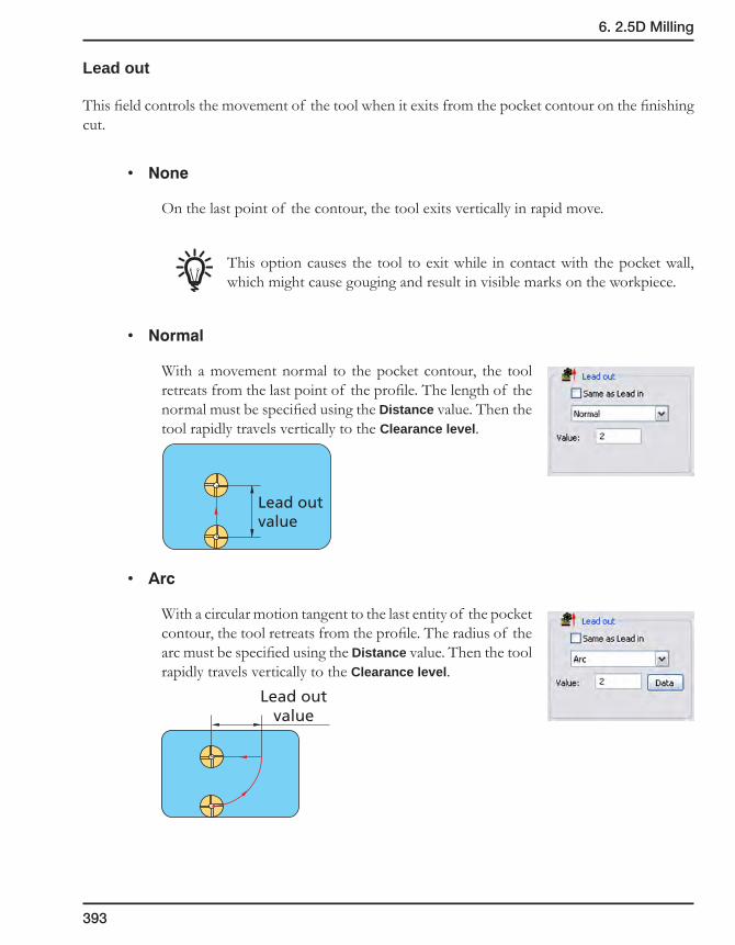
393
6. 2.5D Milling
Lead out
This field controls the movement of the tool when it exits from the pocket contour on the finishing cut.
• None
On the last point of the contour, the tool exits vertically in rapid move.
This option causes the tool to exit while in contact with the pocket wall, which might cause gouging and result in visible marks on the workpiece.
• Normal
With a movement normal to the pocket contour, the tool retreats from the last point of the profile. The length of the normal must be specified using the Distance value. Then the tool rapidly travels vertically to the Clearance level.
• Arc
With a circular motion tangent to the last entity of the pocket contour, the tool retreats from the profile. The radius of the arc must be specified using the Distance value. Then the tool rapidly travels vertically to the Clearance level.
Lead outvalue
Lead outvalue

394
The Data button is displayed. Click on the button to display the Arc Lead Out Data dialog box.
Arc angle
This parameter defines the angle of the lead out arc segment. The default angle value is 90°; in this case, SolidCAM generates a lead out path of quarter arc.
Lead out from
With the Arc Lead out option, the tool moves normal to the lead out arc at the arc start point. The following options are available:
• Distance
The tool starts from the specified distance from the arc start point.
• Center
The tool starts from the lead out arc center.
• Tangent
The tool retreats from the pocket wall in a movement tangent to the last profile entity. The length of the tangent must be entered in the Distance field.
SolidCAM does not check the Lead out movements against the pocket contour. Check the tool path simulation to make sure that the tool does not gouge the pocket walls or islands.
Angle Angle Distance
Lead out from DistanceLead out from Center
Lead outvalue
Normal

395
6. 2.5D Milling
Same as Lead in
When this check box is selected, the strategy and parameters defined for Lead in are used for Lead out.
Keep tool down
This option enables you to reduce the unnecessary tool movements through the Clearance level.
Foe more information, see topic 6.1.3.

396

397
6. 2.5D Milling
6.5 Pocket Recognition Operation
This operation enables you to recognize the pocket features on the solid model and perform the machining of these features.
6.5.1 Geometry page
This page enables you to define the machining geometry for the operation.
Defining the geometry
The automatically recognized geometry consists of planar faces and loops of through pocket features. The definition of the geometry is performed in the Select Faces dialog box.
The major steps of the Pocket Recognition geometry selection are:
• Choose the model configuration used for the recognition;
• Set the selection filter options for Through Pocket and Circular Pocket;
• Set the selection mode;
• Perform the pocket recognition and generate the faces tree;
• Choose the faces you want to include in the operation geometry.

398
Select Faces dialog box
This dialog box enables you to define the parameters of the pocket feature recognition geometry.
• Name
This option enables you to define the name of the geometry. SolidCAM offers you the Default Geometry name (see topic 12.9) that can be edited.
• Configurations
This section enables you to select the SolidWorks model configuration to be used for the geometry definition.
• Selectionmode
This section enables you to set the mode of the geometry selection. The following selection modes are available:
Solid Body
This mode enables you to perform automatic recognition of the pocket features on the picked solid body. All planar faces are recognized with the surface normal vector oriented parallel to the Z-axis of the current CoordSys. The planar faces that cannot be machined with the current CoordSys position (undercuts) cannot be selected (the selection is rejected). All the through pocket areas are recognized according to the Through pocket option.
Z
Selected faces
Undercut face(selection rejected)

399
6. 2.5D Milling
Face
This mode enables you to pick single planar faces. When a face is picked, SolidCAM checks the parallel relation between the surface normal vector of the picked face and the positive direction of the Z-axis of the current CoordSys. If they are not parallel, the face is not selected. The undercut faces that cannot be machined with the current CoordSys position are also not selected. The selection is working in the toggling mode: the first click on a face selects it, the next click on the selected face removes the selection.
Through Pocket Chain
This mode enables you to select the through pockets by picking one of the edges of the lower loop of the pocket area. When the edge is picked, the complete geometry of the through pocket is automatically selected. The lower loop is highlighted on the model. The selection is working in the toggling mode: the first click on an edge selects the loop, the next click on an edge of the already selected loop removes the selection.
• ThroughPocket
When this check box is selected with the Selection mode set to Solid body, the recognition of through pocket features is also performed.
Only the through pocket features where the upper loop is similar to the lower loop are recognized. The through pocket features that cannot be machined with the current CoordSys position cannot be selected.
Through pockets
Upper loop
Lower loop

400
• CircularPocketdiameterfilter
When this check box is selected with the Selection mode set to Solid body, circular pocket features can be selected according to their diameter. All circular pocket features with the diameter greater than the specified Min. Diameter value will be selected. Using this option, you can avoid the machining of the drill features that are supposed to be machined in other operations (Drilling, Drill recognition, etc.).
The Min. Diameter parameter defines the minimum diameter of the pocket features. You may enter the value in the edit box or pick a cylindrical surface or a circular edge in the solid model when the cursor is placed in the Min. Diameter edit box.
When the Apply filter check box is not selected, all recognized circular pocket areas suitable for the current Coordinate System will be selected.
• ModelAppearance
The Transparency option enables you to display the selected solid bodies in the transparent mode.
• Listofrecognizedelements
This section displays the list of all recognized model elements included in the geometry for the operation. Each model element is accompanied by its Z-level value enclosed in parentheses. When an element is selected in the list, it is highlighted on the solid model.
The right-click menu is available on the list items. The Unselect command enables you to remove the current item from the selected geometry. The Unselect All command enables you to remove the selection from all items in the list.
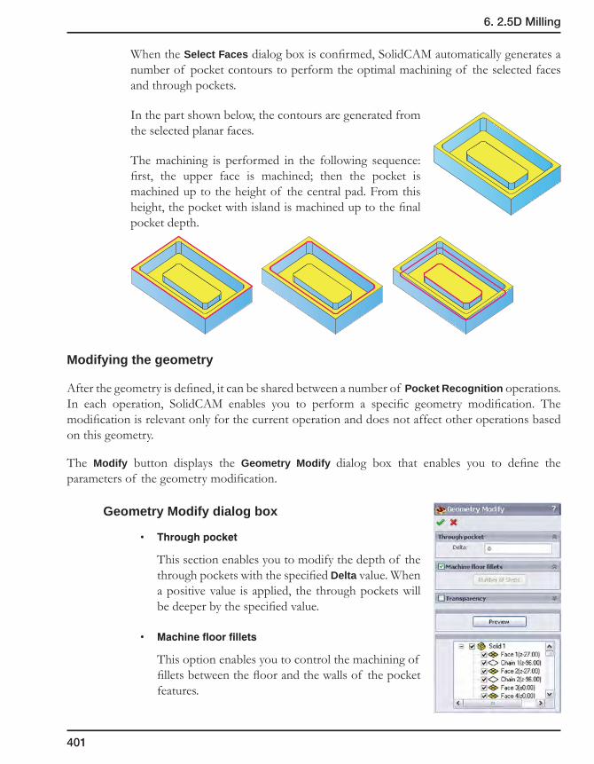
401
6. 2.5D Milling
When the Select Faces dialog box is confirmed, SolidCAM automatically generates a number of pocket contours to perform the optimal machining of the selected faces and through pockets.
In the part shown below, the contours are generated from the selected planar faces.
The machining is performed in the following sequence: first, the upper face is machined; then the pocket is machined up to the height of the central pad. From this height, the pocket with island is machined up to the final pocket depth.
Modifying the geometry
After the geometry is defined, it can be shared between a number of Pocket Recognition operations. In each operation, SolidCAM enables you to perform a specific geometry modification. The modification is relevant only for the current operation and does not affect other operations based on this geometry.
The Modify button displays the Geometry Modify dialog box that enables you to define the parameters of the geometry modification.
Geometry Modify dialog box
• Throughpocket
This section enables you to modify the depth of the through pockets with the specified Delta value. When a positive value is applied, the through pockets will be deeper by the specified value.
• Machinefloorfillets
This option enables you to control the machining of fillets between the floor and the walls of the pocket features.

402
When this option is activated, SolidCAM generates a multi-level pocket geometry evenly distributed along the Z-axis. The machining of this geometry performs the rough machining of the fillets.
The Number of Steps button displays the Fillet Step Number dialog box. This dialog box enables you to control the parameters of the multi-level geometry generation and provides you with the information about the Maximum Fillet Radius found in the geometry.
This dialog box enables you to specify the range of the fillet radii and assign a number of steps to each such range. SolidCAM generates a defined number of evenly distributed Z-levels. At each level, the closed contour is automatically generated.
• Transparency
This section enables you to apply the transparency for the solid bodies used for the geometry definition.
• Preview
This button enables you to display the modified geometry on the solid model. The Resume button enables you to return from the preview state to the dialog box.
• Listofgeometryelements
This list displays the geometry elements included in the current geometry. Each element in the list is accompanied by the following information in parentheses: Z-level at which the element is located, radius of the adjacent fillet and diameter of circular pockets. The check box near each geometry element enables you to exclude the current element from the geometry of the operation. When the check box is selected, the element is machined in the current operation.
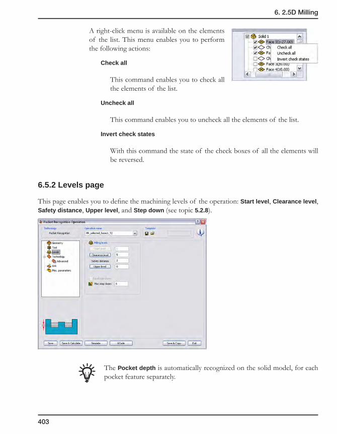
403
6. 2.5D Milling
A right-click menu is available on the elements of the list. This menu enables you to perform the following actions:
Check all
This command enables you to check all the elements of the list.
Uncheck all
This command enables you to uncheck all the elements of the list.
Invert check states
With this command the state of the check boxes of all the elements will be reversed.
6.5.2 Levels page
This page enables you to define the machining levels of the operation: Start level, Clearance level, Safety distance, Upper level, and Step down (see topic 5.2.8).
The Pocket depth is automatically recognized on the solid model, for each pocket feature separately.
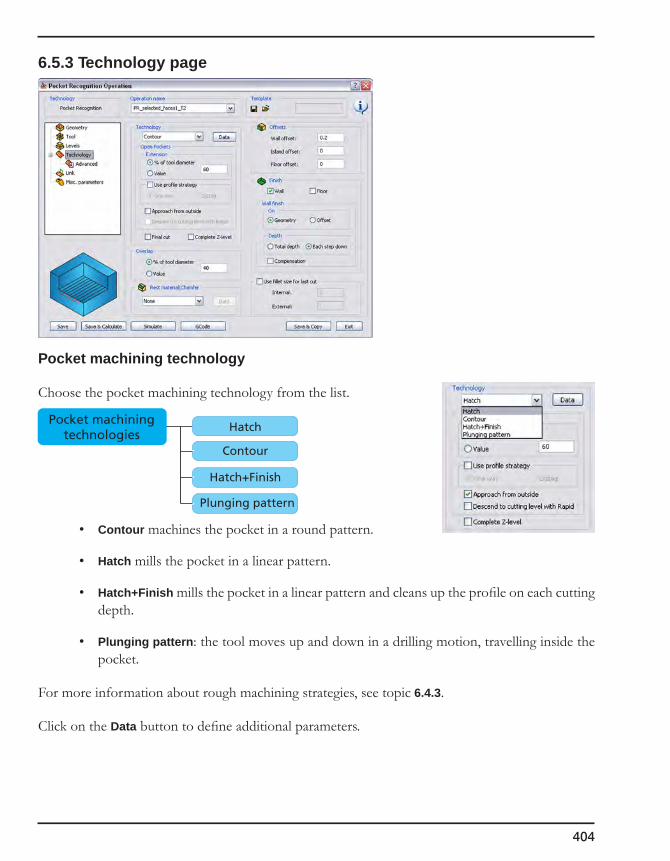
404
6.5.3 Technology page
Pocket machining technology
Choose the pocket machining technology from the list.
• Contour machines the pocket in a round pattern.
• Hatch mills the pocket in a linear pattern.
• Hatch+Finish mills the pocket in a linear pattern and cleans up the profile on each cutting depth.
• Plunging pattern: the tool moves up and down in a drilling motion, travelling inside the pocket.
For more information about rough machining strategies, see topic 6.4.3.
Click on the Data button to define additional parameters.
Pocket machiningtechnologies
Hatch
Contour
Hatch+Finish
Plunging pattern
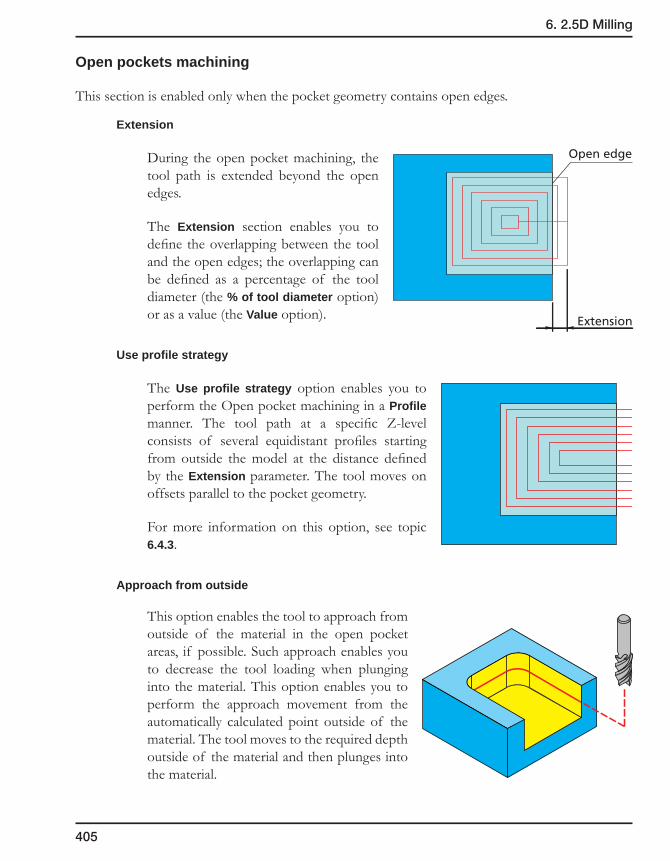
405
6. 2.5D Milling
Open pockets machining
This section is enabled only when the pocket geometry contains open edges.
Extension
During the open pocket machining, the tool path is extended beyond the open edges.
The Extension section enables you to define the overlapping between the tool and the open edges; the overlapping can be defined as a percentage of the tool diameter (the % of tool diameter option) or as a value (the Value option).
Use profile strategy
The Use profile strategy option enables you to perform the Open pocket machining in a Profile manner. The tool path at a specific Z-level consists of several equidistant profiles starting from outside the model at the distance defined by the Extension parameter. The tool moves on offsets parallel to the pocket geometry.
For more information on this option, see topic 6.4.3.
Approach from outside
This option enables the tool to approach from outside of the material in the open pocket areas, if possible. Such approach enables you to decrease the tool loading when plunging into the material. This option enables you to perform the approach movement from the automatically calculated point outside of the material. The tool moves to the required depth outside of the material and then plunges into the material.
Extension
Open edge
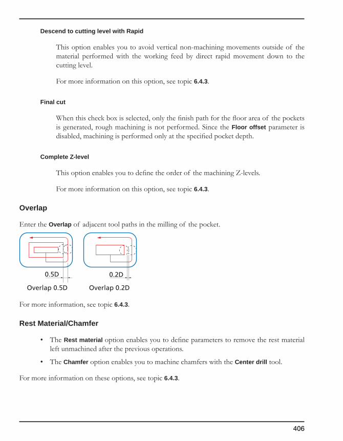
406
Descend to cutting level with Rapid
This option enables you to avoid vertical non-machining movements outside of the material performed with the working feed by direct rapid movement down to the cutting level.
For more information on this option, see topic 6.4.3.
Final cut
When this check box is selected, only the finish path for the floor area of the pockets is generated, rough machining is not performed. Since the Floor offset parameter is disabled, machining is performed only at the specified pocket depth.
Complete Z-level
This option enables you to define the order of the machining Z-levels.
For more information on this option, see topic 6.4.3.
Overlap
Enter the Overlap of adjacent tool paths in the milling of the pocket.
For more information, see topic 6.4.3.
Rest Material/Chamfer
• The Rest material option enables you to define parameters to remove the rest material left unmachined after the previous operations.
• The Chamfer option enables you to machine chamfers with the Center drill tool.
For more information on these options, see topic 6.4.3.
0.5D
Overlap 0.5D
0.2D
Overlap 0.2D

407
6. 2.5D Milling
Offsets
To perform the rough machining of the pocket, you have to specify the offsets on the pocket geometry that will be removed with the finishing cut.
• Wall offset
Enter the offset that will remain on the pocket wall after the roughing cut.
• Island offset
Enter the offset that will remain on the pocket islands after the roughing cut.
• Floor offset
Enter the offset that will remain on the pocket floor after the roughing cut.
Finish
This section enables you to perform the finish machining of the pocket.
The Wall check box enables you to perform finishing of the pocket walls. Only wall and islands are finished on the contour. The pocket depth is reduced by the specified floor offset.
The Floor check box enables you to perform finishing of the pocket floor. The finish cut is executed to remove the floor offset. The specified wall and island offset remain on the pocket contour.
For more information on this option, see topic 6.4.3.
Compensation
If the Compensation check box is selected, the tool radius compensation options G4x of the CNC-controller are used in the GCode.
For more information on this option, see topic 6.1.2.
Fillet size for last cut
This option enables you to add a radius to a sharp corner without changing the geometry.
For more information on this option, see topic 6.1.2.

408
6.5.4 Link page
Ramping
This field controls the way the tool plunges into the material inside the pocket.
For more information about Ramping modes and the corresponding parameters, see topic 6.4.4.
Lead in
In pocket machining, the Lead in option is used for horizontal approach of the tool to the geometry in the machining of the part walls.
This option is available when the Wall check box is selected in the Finish section of the Technology page.
For more information, see topic 6.4.4.
Lead out
This field controls the movement of the tool when it exits from the pocket contour on the finishing cut.
For more information, see topic 6.4.4.
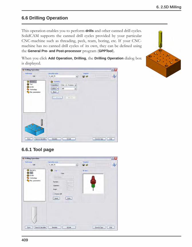
409
6. 2.5D Milling
6.6 Drilling Operation
This operation enables you to perform drills and other canned drill cycles. SolidCAM supports the canned drill cycles provided by your particular CNC-machine such as threading, peck, ream, boring, etc. If your CNC-machine has no canned drill cycles of its own, they can be defined using the General Pre- and Post-processor program (GPPTool).
When you click Add Operation, Drilling, the Drilling Operation dialog box is displayed.
6.6.1 Tool page

410
Center drill
In addition to the standard tool parameters presented on the Tool page, SolidCAM enables you to label a tool as a center drill. This option is used for automatic sorting. In automatic sorting, tools labeled as center drills can be automatically moved to the top of the operation list.
When a Tap tool is chosen for the operation, the Tapping drill cycle type is automatically chosen.
The Drill cycle type button is unavailable. You cannot change the cycle type until the Tap tool is changed to a tool of a different type.
If the Tapping cycle is not supported by the current MAC file, the Tap tool cannot be chosen for the operation. The following error message is displayed when you click on the Select button in the Part Tool Table dialog box.
When you change the MAC file for the CAM-Part that contains tapping operations with a MAC file that does not support tapping, SolidCAM marks all the tapping operations with the asterisk sign (the PCode is removed). When you try to calculate such operations, the following messages are displayed.
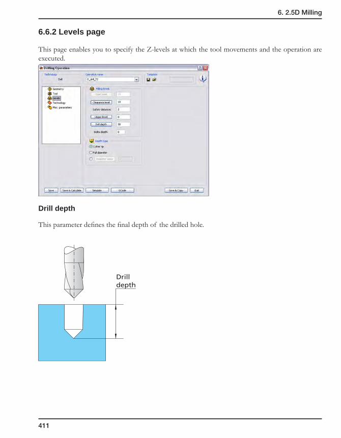
411
6. 2.5D Milling
6.6.2 Levels page
This page enables you to specify the Z-levels at which the tool movements and the operation are executed.
Drill depth
This parameter defines the final depth of the drilled hole.
Drilldepth

412
Depth type
This option enables you to deepen the drilled hole in order to obtain a given diameter at the specified drill depth.
• Cuttertip
The drill tip reaches the defined Drill depth.
• Fulldiameter
The drill reaches the defined Drill depth with the full diameter.
• Diametervalue
The drill reaches the defined Drill depth with the drill cone diameter specified by the Diameter value parameter.
The Diameter value can vary from 0 all the way up to the drill tool diameter. A value greater than the drill tool diameter is automatically decreased to the drill tool diameter.
6.6.3 Technology page
This page enables you to define the technological parameters of drilling.
Drilldepth
Cutter tip Full diameter Diameter value
Drilldepth
Drilldepth
Diametervalue

413
6. 2.5D Milling
Sequence of drill positions
This section enables you to define the sequence of the drill positions, manage its direction, etc.
You can change the order of positions in the sequence by dragging and dropping them in the list section of the Drill Geometry Selection dialog box (see topic 4.2.3).
Default
The drills are performed according to the order in which the drill points were picked during the geometry definition.
Line
This option enables you to define the direction of the sequenced drill positions machining.
You have to define the direction by selecting two points on your model. The drill positions are arranged along the Direction line.
1. Click on the Pick line button.
2. The Pick first point dialog box is displayed. Enter the coordinate values and confirm with the Enter button or pick a position using the SolidWorks selection options.
3. The Pick second point dialog box is displayed. Define the end point of the direction line in the same manner.
4. Click on the Show sorted button to preview the sorted positions.

414
Advanced sorting
This option enables you to sort the drill positions for machining of linear and circular drill patterns.
The button displays the Advanced Sort dialog box.
• Linearsorting
The Linear tab contains the sorting methods appropriate for machining of linear drill patterns.
Linear pattern
According to the linear sorting methods described above, the machining is performed either by rows of drill positions with the same Y-coordinate or by columns of drill positions with the same X-coordinate. The Tolerance parameter enables you to define the tolerance that is used to determine if a drill position belongs to the current row/column or to a different row/column.
If the machining is performed by rows, SolidCAM determines the first drill position for each row (the start position of the first row is the start position of the whole pattern). For each next drill position, SolidCAM determines the Y-coordinate and compares it with the Y-coordinate of the first drill position of the current row. If the linear deviation is within the specified tolerance limit, SolidCAM considers this position to belong to the current row. If the deviation exceeds the tolerance value, the drill position is rejected from the current row; later this position will be checked again for belonging to next rows.
In the similar manner, when the machining is performed by columns, the specified Tolerance value is used to determine whether a specific drill position belongs to the current column. In this case, the deviation of X-coordinates between the first drill position in the column and the current drill position is compared with the tolerance value.

415
6. 2.5D Milling
Linear sorting methods
The following methods are available for advanced linear sorting:
SolidCAM determines the position with the minimal X- and Y-coordinates and accepts it as the start position of the drill sequence. From this position, SolidCAM continues the machining of the drills with the same Y-coordinate; the machining is performed in the direction of increasing X-coordinates.
When the last position of the current Y-coordinate is machined, SolidCAM passes to the next Y-coordinate (in the increasing order) and continues the machining of the next row from the position with the minimal X-coordinate to the position with the maximal X-coordinate (increasing order) and so on. In such manner, the machining of the rows is performed in the same direction of increasing X-coordinates.
The ordering of rows is performed in the direction of increasing Y-coordinates.
SolidCAM determines the position with the minimal X- and Y-coordinates and accepts it as the start position of the drill sequence. From this position, SolidCAM continues the machining of the drills with the same Y-coordinate; the machining is performed in the direction of increasing X-coordinates.
When the last position of the current Y-coordinate is machined, SolidCAM passes to the next Y-coordinate (in the increasing order) and continues the machining of the next row from the position with the maximal X-coordinate to the position with the minimal X-coordinate (decreasing order), and so on. In such manner, the machining of two successive rows is performed in the opposite order: each odd row is machined in the direction of increasing X-coordinates, each even row is machined in the direction of decreasing X-coordinates.
The rows are machined in the direction of the increasing Y-coordinates.

416
SolidCAM determines the position with the minimal X- and Y-coordinates and accepts it as the start position of the drill sequence. From this position, SolidCAM continues the machining of the drills with the same X-coordinate; the machining is performed in the direction of increasing Y-coordinates.
When the last position of the current X-coordinate is machined, SolidCAM passes to the next X-coordinate (in the increasing order) and continues the machining of the next column from the position with the minimal Y-coordinate to the position with the maximal Y-coordinate (increasing order), and so on. In such manner, the machining of the columns is performed in the same direction of increasing Y-coordinates.
The ordering of columns is performed in the direction of increasing X-coordinates.
SolidCAM determines the position with the minimal X- and Y-coordinates and accepts it as the start position of the drill sequence. From this position, SolidCAM continues the machining of the drills with the same X-coordinate; the machining is performed in the direction of increasing Y-coordinates.
When the last position of the current X-coordinate is machined, SolidCAM passes to the next X-coordinate (in the increasing order) and continues the machining of the next column from the position with the maximal Y-coordinate to the position with the minimal Y-coordinate (decreasing order), and so on. In such manner, the machining of two successive columns is performed in the opposite order: each odd column is machined in the direction of increasing Y-coordinates, each even column is machined in the direction of decreasing Y-coordinates.
The columns are ordered in the direction of increasing X-coordinates.
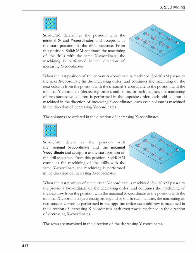
417
6. 2.5D Milling
SolidCAM determines the position with the minimal X- and Y-coordinates and accepts it as the start position of the drill sequence. From this position, SolidCAM continues the machining of the drills with the same X-coordinate; the machining is performed in the direction of increasing Y-coordinates.
When the last position of the current X-coordinate is machined, SolidCAM passes to the next X-coordinate (in the increasing order) and continues the machining of the next column from the position with the maximal Y-coordinate to the position with the minimal Y-coordinate (decreasing order), and so on. In such manner, the machining of two successive columns is performed in the opposite order: each odd column is machined in the direction of increasing Y-coordinates, each even column is machined in the direction of decreasing Y-coordinates.
The columns are ordered in the direction of increasing X-coordinates.
SolidCAM determines the position with the minimal X-coordinate and the maximal Y-coordinate and accepts it as the start position of the drill sequence. From this position, SolidCAM continues the machining of the drills with the same Y-coordinate; the machining is performed in the direction of increasing X-coordinates.
When the last position of the current Y-coordinate is machined, SolidCAM passes to the previous Y-coordinate (in the decreasing order) and continues the machining of the next row from the position with the maximal X-coordinate to the position with the minimal X-coordinate (decreasing order), and so on. In such manner, the machining of two successive rows is performed in the opposite order: each odd row is machined in the direction of increasing X-coordinates, each even row is machined in the direction of decreasing X-coordinates.
The rows are machined in the direction of the decreasing Y-coordinates.

418
SolidCAM determines the position with the minimal X-coordinate and the maximal Y-coordinate and accepts it as the start position of the drill sequence. From this position, SolidCAM continues the machining of the drills with the same X-coordinate; the machining is performed in the direction of decreasing Y-coordinates.
When the last position of the current X-coordinate is machined, SolidCAM passes to the next X-coordinate (in the increasing order) and continues the machining of the next column from the position with the maximal Y-coordinate to the position with the minimal Y-coordinate (decreasing order), and so on. In such manner, the machining of the columns is performed in the same direction of decreasing Y-coordinates.
The ordering of columns is performed in the direction of increasing X-coordinates.
SolidCAM determines the position with the minimal X-coordinate and the maximal Y-coordinate and accepts it as the start position of the drill sequence. From this position, SolidCAM continues the machining of the drills with the same X-coordinate; the machining is performed in the direction of decreasing Y-coordinates.
When the last position of the current X-coordinate is machined, SolidCAM passes to the next X-coordinate (in the increasing order) and continues the machining of the next column from the position with the minimal Y-coordinate to the position with the maximal Y-coordinate (increasing order), and so on. In such manner, the machining of two successive columns is performed in the opposite order: each odd column is machined in the direction of decreasing Y-coordinates, each even column is machined in the direction of increasing Y-coordinates.
The columns are ordered in the direction of increasing X-coordinates.
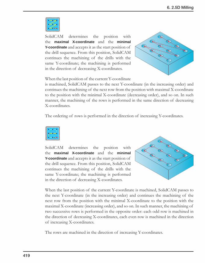
419
6. 2.5D Milling
SolidCAM determines the position with the maximal X-coordinate and the minimal Y-coordinate and accepts it as the start position of the drill sequence. From this position, SolidCAM continues the machining of the drills with the same Y-coordinate; the machining is performed in the direction of decreasing X-coordinates.
When the last position of the current Y-coordinate is machined, SolidCAM passes to the next Y-coordinate (in the increasing order) and continues the machining of the next row from the position with maximal X-coordinate to the position with the minimal X-coordinate (decreasing order), and so on. In such manner, the machining of the rows is performed in the same direction of decreasing X-coordinates.
The ordering of rows is performed in the direction of increasing Y-coordinates.
SolidCAM determines the position with the maximal X-coordinate and the minimal Y-coordinate and accepts it as the start position of the drill sequence. From this position, SolidCAM continues the machining of the drills with the same Y-coordinate; the machining is performed in the direction of decreasing X-coordinates.
When the last position of the current Y-coordinate is machined, SolidCAM passes to the next Y-coordinate (in the increasing order) and continues the machining of the next row from the position with the minimal X-coordinate to the position with the maximal X-coordinate (increasing order), and so on. In such manner, the machining of two successive rows is performed in the opposite order: each odd row is machined in the direction of decreasing X-coordinates, each even row is machined in the direction of increasing X-coordinates.
The rows are machined in the direction of increasing Y-coordinates.
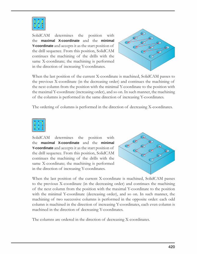
420
SolidCAM determines the position with the maximal X-coordinate and the minimal Y-coordinate and accepts it as the start position of the drill sequence. From this position, SolidCAM continues the machining of the drills with the same X-coordinate; the machining is performed in the direction of increasing Y-coordinates.
When the last position of the current X-coordinate is machined, SolidCAM passes to the previous X-coordinate (in the decreasing order) and continues the machining of the next column from the position with the minimal Y-coordinate to the position with the maximal Y-coordinate (increasing order), and so on. In such manner, the machining of the columns is performed in the same direction of increasing Y-coordinates.
The ordering of columns is performed in the direction of decreasing X-coordinates.
SolidCAM determines the position with the maximal X-coordinate and the minimal Y-coordinate and accepts it as the start position of the drill sequence. From this position, SolidCAM continues the machining of the drills with the same X-coordinate; the machining is performed in the direction of increasing Y-coordinates.
When the last position of the current X-coordinate is machined, SolidCAM passes to the previous X-coordinate (in the decreasing order) and continues the machining of the next column from the position with the maximal Y-coordinate to the position with the minimal Y-coordinate (decreasing order), and so on. In such manner, the machining of two successive columns is performed in the opposite order: each odd column is machined in the direction of increasing Y-coordinates, each even column is machined in the direction of decreasing Y-coordinates.
The columns are ordered in the direction of decreasing X-coordinates.
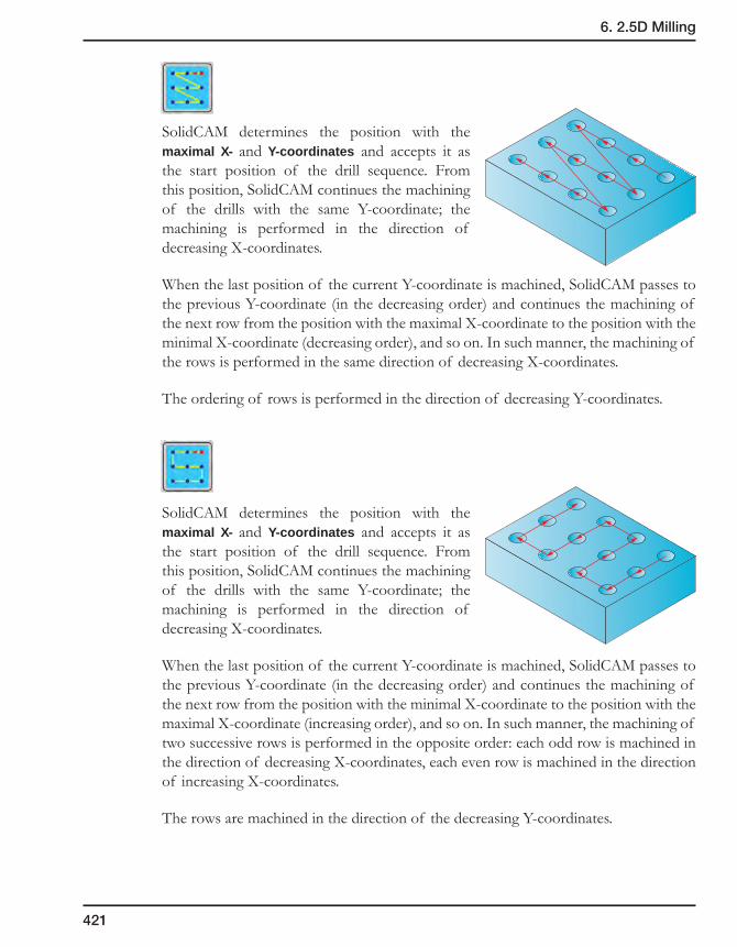
421
6. 2.5D Milling
SolidCAM determines the position with the maximal X- and Y-coordinates and accepts it as the start position of the drill sequence. From this position, SolidCAM continues the machining of the drills with the same Y-coordinate; the machining is performed in the direction of decreasing X-coordinates.
When the last position of the current Y-coordinate is machined, SolidCAM passes to the previous Y-coordinate (in the decreasing order) and continues the machining of the next row from the position with the maximal X-coordinate to the position with the minimal X-coordinate (decreasing order), and so on. In such manner, the machining of the rows is performed in the same direction of decreasing X-coordinates.
The ordering of rows is performed in the direction of decreasing Y-coordinates.
SolidCAM determines the position with the maximal X- and Y-coordinates and accepts it as the start position of the drill sequence. From this position, SolidCAM continues the machining of the drills with the same Y-coordinate; the machining is performed in the direction of decreasing X-coordinates.
When the last position of the current Y-coordinate is machined, SolidCAM passes to the previous Y-coordinate (in the decreasing order) and continues the machining of the next row from the position with the minimal X-coordinate to the position with the maximal X-coordinate (increasing order), and so on. In such manner, the machining of two successive rows is performed in the opposite order: each odd row is machined in the direction of decreasing X-coordinates, each even row is machined in the direction of increasing X-coordinates.
The rows are machined in the direction of the decreasing Y-coordinates.

422
SolidCAM determines the position with the maximal X- and Y-coordinates and accepts it as the start position of the drill sequence. From this position, SolidCAM continues the machining of the drills with the same X-coordinate; the machining is performed in the direction of decreasing Y-coordinates.
When the last position of the current X-coordinate is machined, SolidCAM passes to the previous X-coordinate (in the decreasing order) and continues the machining of the next column from the position with the maximal Y-coordinate to the position with the minimal Y-coordinate (decreasing order) and so on. In such manner, the machining of the columns is performed in the same direction of decreasing Y-coordinates.
The ordering of columns is performed in the direction of decreasing X-coordinates.
SolidCAM determines the position with the maximal X- and Y-coordinates and accepts it as the start position of the drill sequence. From this position, SolidCAM continues the machining of the drills with the same X-coordinate; the machining is performed in the direction of decreasing Y-coordinates.
When the last position of the current X-coordinate is machined, SolidCAM passes to the previous X-coordinate (in the decreasing order) and continues the machining of the next column from the position with the minimal Y-coordinate to the position with the maximal Y-coordinate (increasing order), and so on. In such manner, the machining of two successive columns is performed in the opposite order; each odd column is machined in the direction of decreasing Y-coordinates, each even column is machined in the direction of increasing Y-coordinates.
The columns are ordered in the direction of decreasing X-coordinates.

423
6. 2.5D Milling
Circular sorting
The Circular tab contains the sorting methods appropriate for machining of circular drill patterns.
For the ordering of drill positions by all of the circular sorting methods, SolidCAM uses the center point around which the circular pattern is defined. For each drill position of the chosen geometry, SolidCAM determines the radial vector of the drill position from the center point. For each such vector, SolidCAM determines its length (radius) and the angle between the vector and the X-axis at the center point; these parameters are used for further sorting.
Circular pattern
This section contains the following parameters:
• Startangle
This parameter enables you to define the angle at which the start position will be chosen. This angle is defined according to the positive direction of the X-axis at the pattern center. The default value of the parameter is 0°.
The Pick button enables you to define the Start angle by picking a point on the model. The Pick angle point dialog box enables you to pick the position on the model and displays the coordinates of the picked position.
X
Radius
Angle

424
When the position is picked and the dialog box is confirmed, SolidCAM determines the direction vector from the pattern center towards the picked position. SolidCAM automatically calculates the angle between the direction vector and the X-axis at the pattern center and displays the angle value in the Start angle edit box.
• Tolerance
During the circular sorting, SolidCAM groups the drill positions into groups of those located at the same radius or into groups of those located at the same angle.
The Tolerance value determines if a drill position belongs to the same radius group or not. For each group of drill positions located at the same radius, SolidCAM determines the start position; each additional drill position to be included into this group must be located at the radius that is within the tolerance from the radius of the start position.
For each group of drill positions located at the same angle, SolidCAM determines the start position; each additional drill position to be included into this group must be located at the angle that is within the angular tolerance (calculated automatically according to the specified tolerance) from the angle of the start position.
Change sort center
By default, the pattern center is automatically defined at the origin of the Coordinate System used in the current operation. The Change sort center button enables you to change the pattern center location by picking on the model. The Pick center point dialog box enables you to pick the center position and displays the coordinates of the picked point.
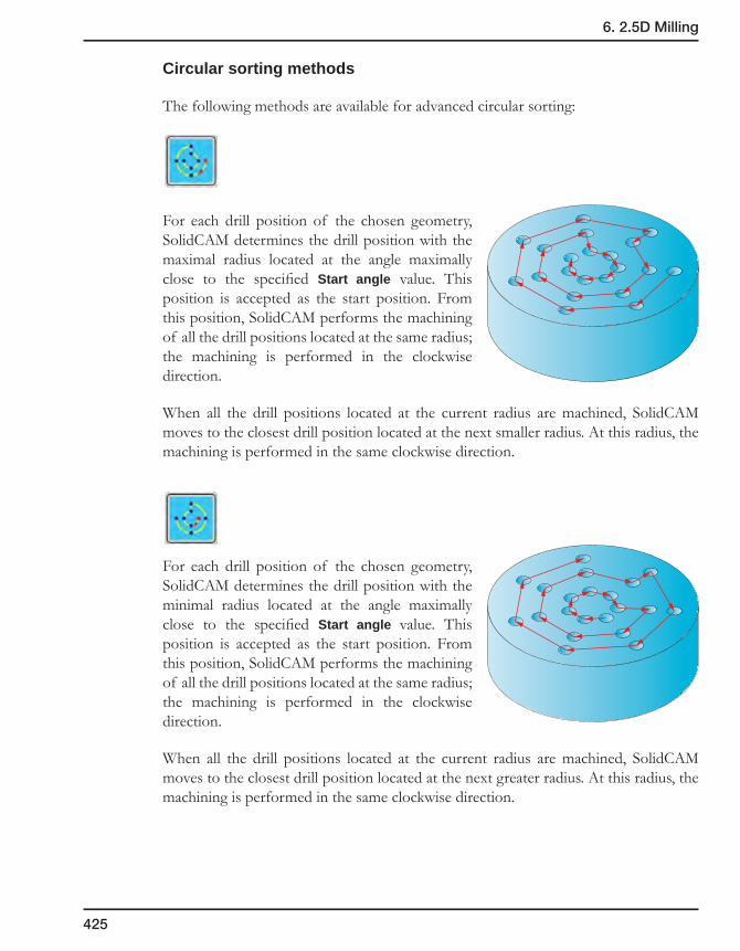
425
6. 2.5D Milling
Circular sorting methods
The following methods are available for advanced circular sorting:
For each drill position of the chosen geometry, SolidCAM determines the drill position with the maximal radius located at the angle maximally close to the specified Start angle value. This position is accepted as the start position. From this position, SolidCAM performs the machining of all the drill positions located at the same radius; the machining is performed in the clockwise direction.
When all the drill positions located at the current radius are machined, SolidCAM moves to the closest drill position located at the next smaller radius. At this radius, the machining is performed in the same clockwise direction.
For each drill position of the chosen geometry, SolidCAM determines the drill position with the minimal radius located at the angle maximally close to the specified Start angle value. This position is accepted as the start position. From this position, SolidCAM performs the machining of all the drill positions located at the same radius; the machining is performed in the clockwise direction.
When all the drill positions located at the current radius are machined, SolidCAM moves to the closest drill position located at the next greater radius. At this radius, the machining is performed in the same clockwise direction.
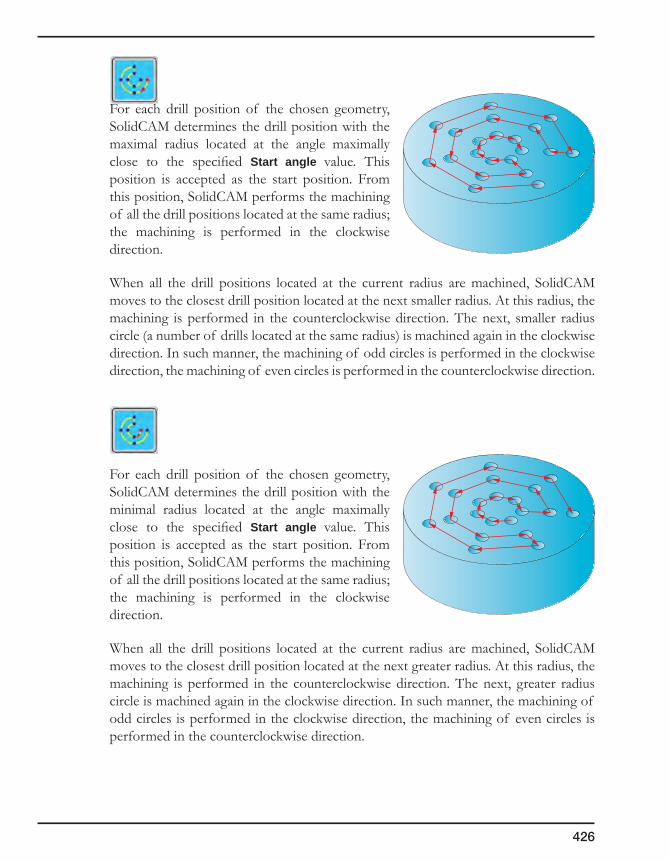
426
For each drill position of the chosen geometry, SolidCAM determines the drill position with the maximal radius located at the angle maximally close to the specified Start angle value. This position is accepted as the start position. From this position, SolidCAM performs the machining of all the drill positions located at the same radius; the machining is performed in the clockwise direction.
When all the drill positions located at the current radius are machined, SolidCAM moves to the closest drill position located at the next smaller radius. At this radius, the machining is performed in the counterclockwise direction. The next, smaller radius circle (a number of drills located at the same radius) is machined again in the clockwise direction. In such manner, the machining of odd circles is performed in the clockwise direction, the machining of even circles is performed in the counterclockwise direction.
For each drill position of the chosen geometry, SolidCAM determines the drill position with the minimal radius located at the angle maximally close to the specified Start angle value. This position is accepted as the start position. From this position, SolidCAM performs the machining of all the drill positions located at the same radius; the machining is performed in the clockwise direction.
When all the drill positions located at the current radius are machined, SolidCAM moves to the closest drill position located at the next greater radius. At this radius, the machining is performed in the counterclockwise direction. The next, greater radius circle is machined again in the clockwise direction. In such manner, the machining of odd circles is performed in the clockwise direction, the machining of even circles is performed in the counterclockwise direction.

427
6. 2.5D Milling
For each drill position of the chosen geometry, SolidCAM determines the drill position with the maximal radius located at the angle maximally close to the specified Start angle value. This position is accepted as the start position. From this position, SolidCAM performs the machining of all the drill positions located at the same radius; the machining is performed in the counterclockwise direction.
When all the drill positions located at the current radius are machined, SolidCAM moves to the closest drill position located at the next smaller radius. At this radius, the machining is performed in the same counterclockwise direction.
For each drill position of the chosen geometry, SolidCAM determines the drill position with the minimal radius located at the angle maximally close to the specified Start angle value. This position is accepted as the start position. From this position, SolidCAM performs the machining of all the drill positions located at the same radius; the machining is performed in the counterclockwise direction.
When all the drill positions located at the current radius are machined, SolidCAM moves to the closest drill position located at the next greater radius. At this radius, the machining is performed in the same counterclockwise direction.
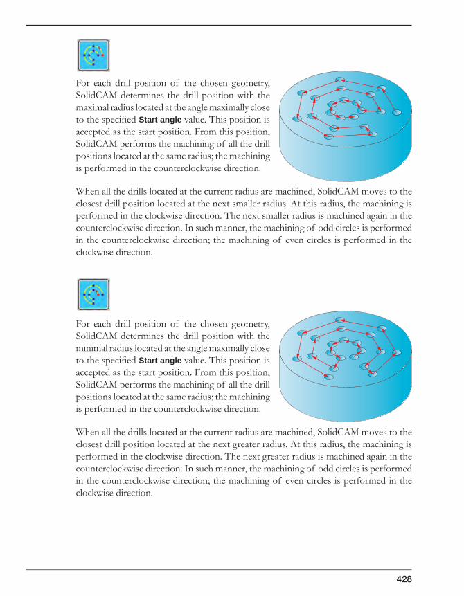
428
For each drill position of the chosen geometry, SolidCAM determines the drill position with the maximal radius located at the angle maximally close to the specified Start angle value. This position is accepted as the start position. From this position, SolidCAM performs the machining of all the drill positions located at the same radius; the machining is performed in the counterclockwise direction.
When all the drills located at the current radius are machined, SolidCAM moves to the closest drill position located at the next smaller radius. At this radius, the machining is performed in the clockwise direction. The next smaller radius is machined again in the counterclockwise direction. In such manner, the machining of odd circles is performed in the counterclockwise direction; the machining of even circles is performed in the clockwise direction.
For each drill position of the chosen geometry, SolidCAM determines the drill position with the minimal radius located at the angle maximally close to the specified Start angle value. This position is accepted as the start position. From this position, SolidCAM performs the machining of all the drill positions located at the same radius; the machining is performed in the counterclockwise direction.
When all the drills located at the current radius are machined, SolidCAM moves to the closest drill position located at the next greater radius. At this radius, the machining is performed in the clockwise direction. The next greater radius is machined again in the counterclockwise direction. In such manner, the machining of odd circles is performed in the counterclockwise direction; the machining of even circles is performed in the clockwise direction.
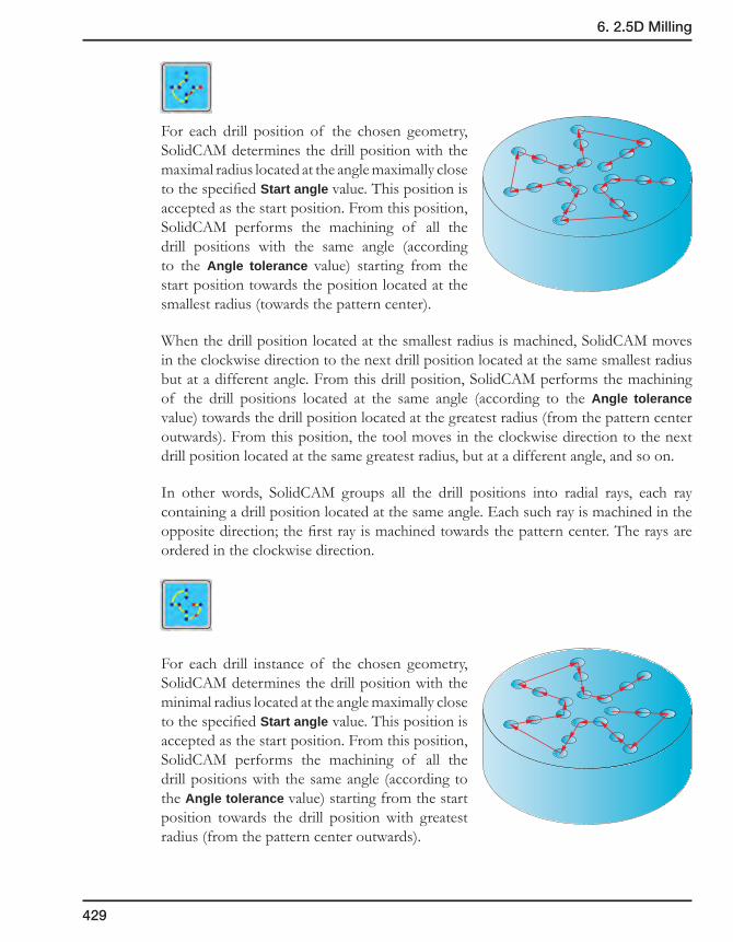
429
6. 2.5D Milling
For each drill position of the chosen geometry, SolidCAM determines the drill position with the maximal radius located at the angle maximally close to the specified Start angle value. This position is accepted as the start position. From this position, SolidCAM performs the machining of all the drill positions with the same angle (according to the Angle tolerance value) starting from the start position towards the position located at the smallest radius (towards the pattern center).
When the drill position located at the smallest radius is machined, SolidCAM moves in the clockwise direction to the next drill position located at the same smallest radius but at a different angle. From this drill position, SolidCAM performs the machining of the drill positions located at the same angle (according to the Angle tolerance value) towards the drill position located at the greatest radius (from the pattern center outwards). From this position, the tool moves in the clockwise direction to the next drill position located at the same greatest radius, but at a different angle, and so on.
In other words, SolidCAM groups all the drill positions into radial rays, each ray containing a drill position located at the same angle. Each such ray is machined in the opposite direction; the first ray is machined towards the pattern center. The rays are ordered in the clockwise direction.
For each drill instance of the chosen geometry, SolidCAM determines the drill position with the minimal radius located at the angle maximally close to the specified Start angle value. This position is accepted as the start position. From this position, SolidCAM performs the machining of all the drill positions with the same angle (according to the Angle tolerance value) starting from the start position towards the drill position with greatest radius (from the pattern center outwards).

430
When the drill position with the greatest radius is machined, SolidCAM moves in the clockwise direction to the next drill position located at the same greatest radius but at a different angle. From this drill position, SolidCAM performs the machining of the drill position located at the same angle (according to the Angle tolerance value) towards the drill position located at the smallest radius (towards the pattern center). From this position, the tool moves in the clockwise direction to the next drill position located at the same smallest radius, but at a different angle, and so on.
In other words, SolidCAM groups all the drill positions into radial rays, each ray containing the drill position located at the same angle. Each such ray is machined in the opposite direction; the first ray is machined from the pattern center outwards. The rays are ordered in the clockwise direction.
For each drill instance of the chosen geometry, SolidCAM determines the drill position with the maximal radius located at the angle maximally close to the specified Start angle value. This position is accepted as the start position. From this position, SolidCAM performs the machining of all the drill positions located with the same angle (according to the Angle tolerance value) starting from the start position towards the smallest radius (towards the pattern center).
When the drill position with the smallest radius is machined, SolidCAM moves in the counterclockwise direction to the next drill position located at the same smallest radius but at a different angle. From this drill position, SolidCAM performs the machining of drill positions located at the same angle (according to the Angle tolerance value) towards the drill position located at the greatest radius (from the pattern center outwards). From this position, the tool moves in the counterclockwise direction to the next drill position located at the same greatest radius, but at a different angle, and so on.
In other words, SolidCAM groups all the drill positions into radial rays, each ray containing the drill position located at the same angle. Each such ray is machined in the opposite direction; the first ray is machined towards the pattern center. The rays are ordered in the counterclockwise direction.

431
6. 2.5D Milling
For each drill instance of the chosen geometry, SolidCAM determines the drill position with the minimal radius located at the angle maximally close to the specified Start angle value. This position is accepted as the start position. From this position, SolidCAM performs the machining of all the drill positions located with the same angle (according to the Angle tolerance value) starting from the start position towards the drill position with the greatest radius (from the pattern center outwards).
When the drill position with the greatest radius is machined, SolidCAM moves in the counterclockwise direction to the next drill position located at the same greatest radius but at a different angle. From this drill position, SolidCAM performs the machining of drill positions located at the same angle (according to the Angle tolerance value) towards the drill position located at the smallest radius (towards the pattern center). From this position, the tool moves in the counterclockwise direction to the next drill position located at the same smallest radius, but at a different angle, and so on.
In other words, SolidCAM groups all the drill positions into radial rays, each ray containing the drill position located at the same angle. Each such ray is machined in the opposite direction; the first ray is machined from the pattern center outwards. The rays are ordered in the counterclockwise direction.
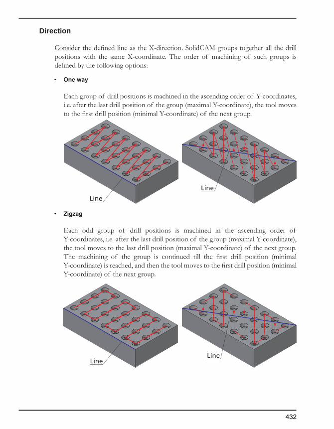
432
Direction
Consider the defined line as the X-direction. SolidCAM groups together all the drill positions with the same X-coordinate. The order of machining of such groups is defined by the following options:
• Oneway
Each group of drill positions is machined in the ascending order of Y-coordinates, i.e. after the last drill position of the group (maximal Y-coordinate), the tool moves to the first drill position (minimal Y-coordinate) of the next group.
• Zigzag
Each odd group of drill positions is machined in the ascending order of Y-coordinates, i.e. after the last drill position of the group (maximal Y-coordinate), the tool moves to the last drill position (maximal Y-coordinate) of the next group. The machining of the group is continued till the first drill position (minimal Y-coordinate) is reached, and then the tool moves to the first drill position (minimal Y-coordinate) of the next group.
Line
Line
LineLine

433
6. 2.5D Milling
Distance
This option minimizes the length of the necessary tool movement. The first drill is performed at the first point defined in the drill geometry. Any other drill is executed at the nearest position, i.e. at the shortest distance to the previous drill position.
Reverse drilling sequence
SolidCAM enables you to reverse the sequence of drilling positions in Drilling operations. This functionality enables you to optimize the rapid movements during the machining and increase the machining speed.
The Reverse check box enables you to reverse the sequence of drilling positions as shown.
When the same sequence of drilling positions is used in several drilling operations (e.g. center drilling, drilling and threading) the sequence reversing enables you to reduce rapid movements between the operations.
This option is available only when the drill_proc parameter is set to N in the MAC file.
Show sorted
This button displays the sorted sequence of drill positions on the solid model.
1
2
3
4
5
6
Original sequence
Reversed sequence
1
2
3
4
5
6
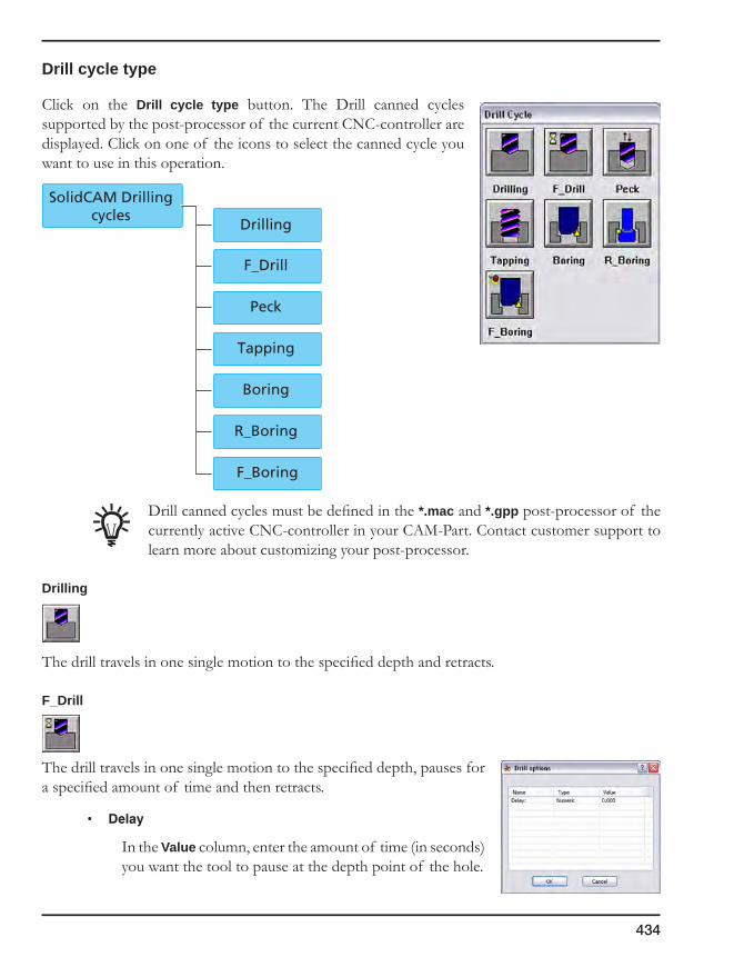
434
Drill cycle type
Click on the Drill cycle type button. The Drill canned cycles supported by the post-processor of the current CNC-controller are displayed. Click on one of the icons to select the canned cycle you want to use in this operation.
Drill canned cycles must be defined in the *.mac and *.gpp post-processor of the currently active CNC-controller in your CAM-Part. Contact customer support to learn more about customizing your post-processor.
Drilling
The drill travels in one single motion to the specified depth and retracts.
F_Drill
The drill travels in one single motion to the specified depth, pauses for a specified amount of time and then retracts.
• Delay
In the Value column, enter the amount of time (in seconds) you want the tool to pause at the depth point of the hole.
SolidCAM Drillingcycles
Drilling
F_Drill
Peck
Tapping
Boring
R_Boring
F_Boring
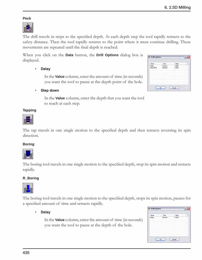
435
6. 2.5D Milling
Peck
The drill travels in steps to the specified depth. At each depth step the tool rapidly retracts to the safety distance. Then the tool rapidly returns to the point where it must continue drilling. These movements are repeated until the final depth is reached.
When you click on the Data button, the Drill Options dialog box is displayed.
• Delay
In the Value column, enter the amount of time (in seconds) you want the tool to pause at the depth point of the hole.
• Stepdown
In the Value column, enter the depth that you want the tool to reach at each step.
Tapping
The tap travels in one single motion to the specified depth and then retracts reversing its spin direction.
Boring
The boring tool travels in one single motion to the specified depth, stop its spin motion and retracts rapidly.
R_Boring
The boring tool travels in one single motion to the specified depth, stops its spin motion, pauses for a specified amount of time and retracts rapidly.
• Delay
In the Value column, enter the amount of time (in seconds) you want the tool to pause at the depth of the hole.
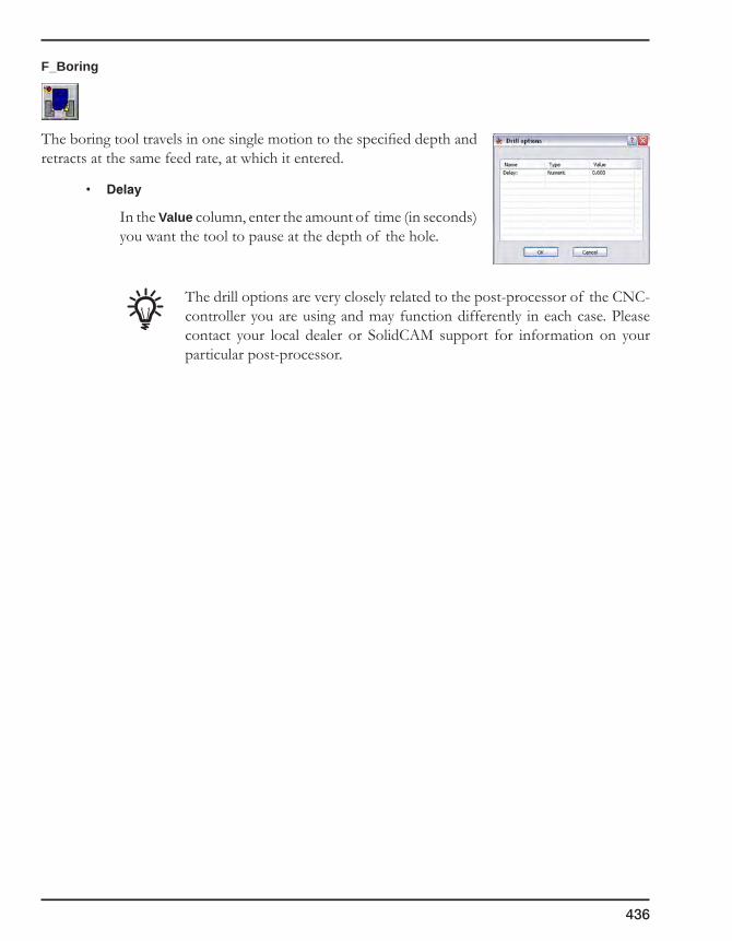
436
F_Boring
The boring tool travels in one single motion to the specified depth and retracts at the same feed rate, at which it entered.
• Delay
In the Value column, enter the amount of time (in seconds) you want the tool to pause at the depth of the hole.
The drill options are very closely related to the post-processor of the CNC-controller you are using and may function differently in each case. Please contact your local dealer or SolidCAM support for information on your particular post-processor.

437
6. 2.5D Milling
6.7 Drill Recognition Operation
The Drill Recognition operation performs powerful drill feature recognition and automatic Drill geometry creation using SolidCAM AFRM module functionality. This operation enables you to handle separate sets of Milling levels for each drill position. The initial values of the Milling levels sets are automatically recognized from the model; they can be edited by the user.
6.7.1 Geometry page
The geometry for the Drill Recognition operation is defined using the AFRM functionality and is automatically recognized on the Target model, therefore the Target model must be defined in the CAM-Part before you define the operation. The hole recognition is performed in the direction parallel to the Z-axis of the Coordinate System chosen for the operation.
The definition of the geometry is performed in the HR Drill Geometry Selection dialog box.
The major steps of the HR Drill Geometry selection:
• Choose the model configuration used for the recognition;
• Set the selection filter options (Hole type, Hole diameter, Hole Upper level and Hole Height);
• Perform the holes recognition and generate the recognized holes tree;
• Choose the holes you want to include in the operation geometry;
• Preview the machining sequence.

438
HR Drill Geometry Selection dialog box
This dialog box enables you to define the geometry and manage the parameters of the drill recognition.
Name
This option enables you to define the name of the geometry. SolidCAM offers you the Default Geometry name (see topic 12.9) that can be edited.
Hole type
This section sets the recognition filter of hole features according to their type.
The Through check box enables you to recognize the through hole features.
The Blind check box enables you to recognize the blind hole features.
When none of these check boxes is selected, hole recognition cannot be performed and the Find Holes button is disabled.
Hole diameter (d)
When this section is activated, the hole features are filtered according to the diameter of the hole. With this filter, only the hole features with the Hole diameter value within the specified range are recognized.
The From and To values enable you to define the Diameter range by entering the values or by picking on the solid model. When the cursor is placed in the From/To edit box, you can specify the diameter value by picking a specific cylindrical surface or a circular edge on the solid model. When a cylindrical surface or a circular edge is picked, its diameter is calculated and inserted into the corresponding edit box replacing the previous value. The edit box becomes pink. When you remove the automatically determined value, the edit box becomes white.

439
6. 2.5D Milling
The Thread only check box enables you to recognize only the hole features with threads. The thread recognition is performed according to the SolidCAM Settings. When this check box is selected, the From and To values define the range of the Thread diameter values. The From and To values can be defined by picking a cylindrical surface, cosmetic thread or circular edge on the solid model.
Hole Upper level (u)
When this section is activated, the hole features are filtered according to the Upper level. With this filter, only the hole features with the Upper level value within the specified range are recognized.
The From and To values enable you to define the Upper level range by entering the values or by picking on the solid model. When the cursor is placed in the From/To edit box, you can specify the Upper level value by picking on the solid model. When a model point is picked, the Z-value of the picked position is calculated and inserted into the corresponding edit box replacing the previous value. The edit box becomes pink. When you remove the automatically determined value, the edit box becomes white.
Hole height (h)
When this section is activated, the hole features are filtered according to the Hole height. With this filter, only the hole features with the Hole height value within the specified range are recognized.
The From and To values enable you to define the Hole height range by entering the values or by picking on the solid model. When the cursor is placed in the From/To edit box, you can specify the Hole height value by picking on the solid model. When a model point is picked, the Z-value of the picked position is calculated and inserted into the corresponding edit box replacing the previous value. The edit box becomes pink. When you remove the automatically determined value, the edit box becomes white.
Found holes Undo/Redo
This section provides you with the Undo/Redo buttons that enable you to go back/forward to a specific choice of holes found with a specific set of filter parameters.
Options
• Find Holes
This button performs the holes recognition and filtering of the recognized holes according to the criteria described above. The hole features matching the specified filter criteria will be displayed in the Holes Tree list.

440
Actually, the holes recognition is not performed each time when you click on the Find Holes button. When the holes recognition is performed the first time for a specific Z-axis direction, the recognized holes data is stored in the database and can be used for further geometry definition. When you click on the Find Holes button, SolidCAM retrieves the data from the database according to the filter settings and checks the synchronization between the data and the solid model. If the data in the database is not synchronized, a new holes recognition process is performed and filtering is reapplied.
• Preview
This button displays the current drill geometry based on selected items in the Holes Tree list and the initial machining sequence.
Click on the Resume button to return to the geometry definition.
Holes Tree
In the Holes Tree list, the hole features are classified into Shapes and Groups. A Shape contains all the hole features with the same topology; within a Shape, the Groups include all the hole features with the same dimensions.
The check box near each item in the Holes Tree list enables you to select this item and include it in the current drill geometry. When a Group or a Shape is selected, all the hole features belonging to them are selected. The selected items are highlighted on the model.
The right-click menu is available on the items in the list.
• The Select all command enables you to select all the recognized hole features and include in the drill geometry.
• The Unselect all command enables you to remove the selection from all the hole features in the list.
• The Show hole command displays the Hole Picture and Hole Parameters dialog boxes.
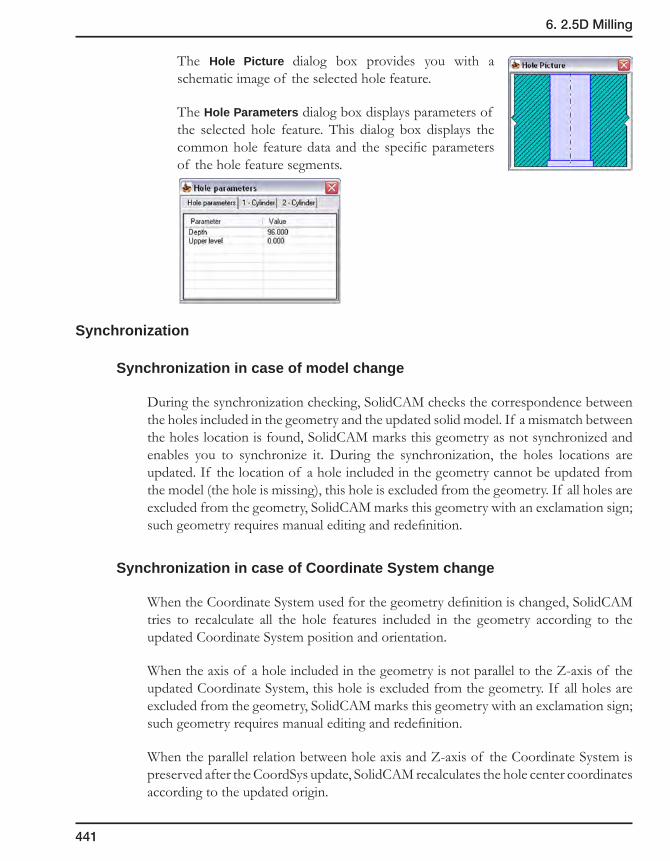
441
6. 2.5D Milling
The Hole Picture dialog box provides you with a schematic image of the selected hole feature.
The Hole Parameters dialog box displays parameters of the selected hole feature. This dialog box displays the common hole feature data and the specific parameters of the hole feature segments.
Synchronization
Synchronization in case of model change
During the synchronization checking, SolidCAM checks the correspondence between the holes included in the geometry and the updated solid model. If a mismatch between the holes location is found, SolidCAM marks this geometry as not synchronized and enables you to synchronize it. During the synchronization, the holes locations are updated. If the location of a hole included in the geometry cannot be updated from the model (the hole is missing), this hole is excluded from the geometry. If all holes are excluded from the geometry, SolidCAM marks this geometry with an exclamation sign; such geometry requires manual editing and redefinition.
Synchronization in case of Coordinate System change
When the Coordinate System used for the geometry definition is changed, SolidCAM tries to recalculate all the hole features included in the geometry according to the updated Coordinate System position and orientation.
When the axis of a hole included in the geometry is not parallel to the Z-axis of the updated Coordinate System, this hole is excluded from the geometry. If all holes are excluded from the geometry, SolidCAM marks this geometry with an exclamation sign; such geometry requires manual editing and redefinition.
When the parallel relation between hole axis and Z-axis of the Coordinate System is preserved after the CoordSys update, SolidCAM recalculates the hole center coordinates according to the updated origin.
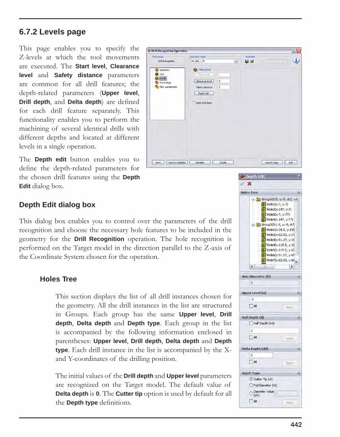
442
6.7.2 Levels page
This page enables you to specify the Z-levels at which the tool movements are executed. The Start level, Clearance level and Safety distance parameters are common for all drill features; the depth-related parameters (Upper level, Drill depth, and Delta depth) are defined for each drill feature separately. This functionality enables you to perform the machining of several identical drills with different depths and located at different levels in a single operation.
The Depth edit button enables you to define the depth-related parameters for the chosen drill features using the Depth Edit dialog box.
Depth Edit dialog box
This dialog box enables you to control over the parameters of the drill recognition and choose the necessary hole features to be included in the geometry for the Drill Recognition operation. The hole recognition is performed on the Target model in the direction parallel to the Z-axis of the Coordinate System chosen for the operation.
Holes Tree
This section displays the list of all drill instances chosen for the geometry. All the drill instances in the list are structured in Groups. Each group has the same Upper level, Drill depth, Delta depth and Depth type. Each group in the list is accompanied by the following information enclosed in parentheses: Upper level, Drill depth, Delta depth and Depth type. Each drill instance in the list is accompanied by the X- and Y-coordinates of the drilling position.
The initial values of the Drill depth and Upper level parameters are recognized on the Target model. The default value of Delta depth is 0. The Cutter tip option is used by default for all the Depth type definitions.

443
6. 2.5D Milling
All drill instances in the list can be selected. When one of them is selected, the relevant parameters are displayed in the Upper level, Drill depth, Delta depth and Depth type sections. The selected groups and drill instances are highlighted on the solid model.
The right-click menu is available on each item in the list.
• Restore Data from Model
This command enables you to restore and assign to selected item (a group or a single drill instance) the Upper level and Drill depth recognized on the Target model. The Delta depth value is restored to 0. The Depth type option is restored to Cutter tip. When the Restore Data from Model command is applied, SolidCAM checks the Holes tree items and reorganizes them into groups according to the changed parameters.
• Restore Data from Model to All
This command restores the Upper level, Drill depth, Delta depth and Depth type data for all the drill instances in the list. When the Restore Data from Model to All command is applied, SolidCAM checks the Holes tree items and reorganizes them into groups according to the changed parameters.
Diameter (D)
This section enables you to set the diameter value and apply it to a single hole, a group or all holes.
Upper level (u)
This section enables you to set the value of the Upper level and apply it to a single hole, a group or all holes.
The edit box displays the Upper level value of the selected item (a group or a hole). The edit box enables you to enter the value or pick the value directly from the model (when the cursor is placed in the edit box). SolidCAM enables you to pick planar faces parallel to the XY-plane of the Coordinate System, model vertices and sketch points. When a model is picked, the Z-value of the picked position is displayed in the edit box. The edit box has pink background, which means that the parameter is defined associatively to the solid model. When the edit box value is typed in, it is not associative to the model; in this case the edit box has white background.
444
The Apply button enables you to apply the defined Upper level value to the selected list item (a group or a hole). When a new Upper level value is applied, SolidCAM checks the Holes tree items and reorganizes them into groups according to the changed parameters. SolidCAM checks all the groups to find a group with identical Upper level, Drill depth, Delta depth and Depth type parameters. If such group is found, SolidCAM adds the updated drill to this group. In case of absence of a suitable group, a new group is created; the updated drill instance is added to this group. The Apply button is not available until you change the value in the edit box.
The All check box enables you to apply the updated Upper level value to all drill instances.
Drill depth (d)
This section enables you to define the value of the drilling depth and apply it to a single hole, a group or all holes.
The edit box displays the Drill depth value of the selected item (a group or a hole). The edit box enables you enter the value or pick the value directly from the model (when the cursor is placed in the edit box). SolidCAM enables you to pick drill faces or edges. SolidCAM determines the depth of the picked drill according to the defined Upper level and displays the value in the edit box. The edit box has pink background, which means that the parameter is defined associatively to the solid model. When the edit box value is typed in, it is not associative to the model; in this case the edit box has white background.
The Apply button enables you to apply the defined Drill depth value to the selected list item (a group or a hole). When a new Drill depth value is applied, SolidCAM checks the Holes tree items and reorganizes them into groups according to the changed parameters. SolidCAM checks all groups to find a group with identical Upper level, Drill depth, Delta depth and Depth type parameters. If such group is found, SolidCAM adds the updated drill to this group. In case of absence of a suitable group, a new group is created; the updated drill instance is added to this group.
The Apply button is not available until you change the value in the edit box.
The All check box enables you to apply the updated Drill depth value to all drill instances.
Delta depth (dd)
This section enables you to set the Delta depth value and apply it to a single hole, a group or all holes.
The edit box displays the Delta depth value of the selected item (a group or a hole). The default value is 0.

445
6. 2.5D Milling
The Apply button enables you to apply the defined Delta depth value to the selected list item (a group or a hole). When a new Delta depth value is applied, SolidCAM checks the Holes tree items and reorganizes them into groups according to the changed parameters. SolidCAM checks all groups to find a group with identical Upper level, Drill depth, Delta depth and Depth type parameters. If such group is found, SolidCAM adds the updated drill to this group. In case of absence of a suitable group, a new group is created; the updated drill instance is added to this group.
The Apply button is not available until you change the value in the edit box.
The All check box enables you to apply the updated Delta depth value to all the drill instances.
Depth type
This section enables you to define the Depth type for a single hole, a group or all holes. You can define the diameter on the conical part of the drilling tool that will reach the specified drilling depth during the machining. You can also deepen a drilled hole in order to obtain a given diameter at the specified drill depth.
The following options are available:
• Cutter tip
The drill tip reaches the defined drilling depth.
• Full diameter
The drill reaches the defined drilling depth with the full diameter.
• Diameter value
The drill reaches the defined drilling depth with the drill cone diameter specified by the Diameter value parameter.
When this option is chosen for chamfer machining, SolidCAM determines the diameter of the upper cylindrical segment of the drill instance and compares it with the tool diameter. If the determined diameter is smaller than the tool diameter, the determined diameter is accepted as the default for the Diameter value. If the determined diameter is greater than or equal to the tool diameter, the tool diameter value is accepted as the default for the Diameter value parameter.
The Apply button enables you to apply the defined Depth type to the selected list item (a group or a hole). When a new Depth type is applied, SolidCAM checks the Holes tree items and reorganizes them into groups according to the changed parameters. SolidCAM checks all groups to find a group with identical Upper level, Drill depth, Delta depth and Depth type parameters. If such group is found, SolidCAM adds the updated drill to this group.
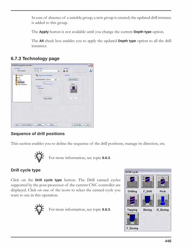
446
In case of absence of a suitable group, a new group is created; the updated drill instance is added to this group.
The Apply button is not available until you change the current Depth type option.
The All check box enables you to apply the updated Depth type option to all the drill instances.
6.7.3 Technology page
Sequence of drill positions
This section enables you to define the sequence of the drill positions, manage its direction, etc.
For more information, see topic 6.6.3.
Drill cycle type
Click on the Drill cycle type button. The Drill canned cycles supported by the post-processor of the current CNC-controller are displayed. Click on one of the icons to select the canned cycle you want to use in this operation.
For more information, see topic 6.6.3.

447
6. 2.5D Milling
6.8 Thread Milling Operation
The Thread Milling operation enables you to generate a helical tool path for the machining of internal and external threads with thread mills.
Most current CNC-controllers have a standard feature called helical interpolation. This feature is used to make a circular move in two axes and a linear move in a third axis. In thread milling, this feature is used to form a circular motion in X and Y and a linear motion in the Z-axis.
The X and Y circular motion forms the diameter to be thread-milled. The Z-axis linear motion forms the actual pitch (or lead) of the thread.
The Thread Milling Operation dialog box enables you to define the parameters of thread milling.
6.8.1 Tool page
This page enables you to choose the tool for the operation from the Part Tool Table. This section also displays the major parameters of the chosen tool: Tool type, Number, Diameter, Pitch, Number of threads, and the chosen Standard table.
Only tools of the Thread Mill/Thread Taper type can be chosen for the operation.

448
6.8.2 Levels page
Depth definition
This section enables you to define the depth of the thread by Value or by Number of threads.
The generated helical tool path is affected by the following tool parameters: Pitch and Number of threads.
Additional depth
This option enables you to deepen the threading by a certain value.
In the Deeper field, enter the additional depth value required.
Start from beginning
When you have added a certain depth to be thread-milled, there is in some cases a need to start the cutting of the thread from the beginning. This is possible with the Start from beginning check box.
For example, you thread-milled one drill hole out of 10 identical holes to a certain depth. Then you found that the threading is not deep enough, and added a certain additional depth. Then you thread-milled the hole again (without starting from the beginning, because there is no point in cutting the thread again where it is already cut) and made sure that the depth is now satisfactory. To thread-mill the rest of the holes, you need to start cutting from the very beginning, because these holes were not previously machined, as the first hole.

449
6. 2.5D Milling
6.8.3 Technology page
Sequence of thread positions
This section enables you to define the sequence of the thread positions, manage its direction, etc.
• Default
The threads are performed according to the order in which the center points were picked during the geometry definition.
• Line
This option enables you to define the direction of the sequenced thread positions machining.
• Distance
This option minimizes the length of the necessary tool movement. The first thread is performed at the first point defined in the geometry. Subsequent threads are executed according to the nearest position, i.e. at the shortest distance to the previous thread position.
• Advanced sorting
This option enables you to sort the drill positions for machining of linear and circular drill patterns.
Show sorted
This button displays the sorted sequence of drill positions on the solid model.
For more information, see topic 6.6.3.

450
Compensation
If the Compensation check box is selected, the tool radius compensation options G4x of the CNC- controller are used in the GCode.
Thread data
This section enables you to define the geometry parameters of the thread.
Type
This section enables you to choose the Internal or External type of machining. The Majorthreaddiameterparameter enables you to define the largest diameter of the machined thread.
Direction
This section enables you to choose either Left hand or Right hand direction of the machined thread.
Cut from
This section enables you to define the direction of thread machining. The thread can be machined either from Top to bottom or from Bottom to top.
Internal External
Major thread diameterMajor thread diameter
Left hand Right hand
Top to bottom Bottom to top

451
6. 2.5D Milling
Multi-Passes
• Rough
This section defines the parameters of the rough machining of the thread. It generates several concentric helical passes that start at the Clear offset distance from the thread and finish up to the thread, thus cutting the thread profile in a number of constant Step over steps.
The Step over value defines the offset between two successive concentric helical profiles.
The Thread offset value defines the distance that remains after the last step over up to the finish pass.
• Finish
This section enables you to perform the thread finishing.
The Number of passes parameter enables you to define the number of finish paths generated to achieve the best surface quality.
Start Angle
This parameter defines the start angle of the thread relative to the X-axis direction.
Clear offset
Step over
Start angle

452
6.8.4 Link page
Lead in/out arc
Arc radius
This box defines the radius of the arc with which the tool enters and exits the material.
This option is available only for the external threading.
Flat approach/Flat retreat
The tool enters and exits the material (depending on the direction set in the Cut from section) at the height of the lower plane of the thread hole.

453
6. 2.5D Milling
6.9 Slot Operation
This operation generates a tool path along the centerline to the right or to the left of one or more profiles. Two types of slots can be defined: the Slot with constant depth operation machines the slot in several steps until the final depth is reached. In Slot with variable depth, the depth profile is also defined by a 2D section. The slot can be pre-machined using rough and semi-finish cycles. The finish cut produces a tool path according to the specified scallop height on the floor of the slot. With available parameters for the right and left extension and the side step, you can mill a slot wider than the tool diameter.
When you click Add Operation, Slot, the Slot Operation dialog box is displayed.

454
6.9.1 Technology page
Depth type
There are two methods to define the depth of the slot.
Choose the depth type (Constant or Section) and click on the Data button to enter additional parameters.
Constant depth type
This option produces a slot with a uniform depth. The Constant Depth Data dialog box is displayed.
SolidCAM Slotdepth types
SectionConstant

455
6. 2.5D Milling
Tool side
Specify the side of the slot profile at which you want to mill. The tool side is always relative to the direction of the slot chain geometry.
• Right: the tool cuts on the right side of the profile geometry at the distance defined as the value of Profile offset.
• Left: the tool cuts on the left side of the profile geometry at the distance defined by the value of Profile offset.
• Center: the center of the tool moves on the profile geometry (the cutter radius compensation G4x cannot be used with this option).
When the Zigzag option is used, the Tool side combo-box defines the tool location for the first cut. For each successive cutting pass, the tool position is changed relative to the geometry direction.
Profile offset remains at the left or right side of the profile after machining.
If the Compensation check box is selected, the tool radius compensation options G4x of the CNC-controller are used in the GCode.
Depth cutting type
• The One way option enables you to create the tool path with only one-directional movements.
• The Zigzag option enables you to create the tool path with bi-directional movements.
Slot extension
This option enables you to extend the end of the slot without additional geometric construction and without editing the slot geometry. The Distance parameter controls the slot extension.
Zigzag One way

456
Fillet size for last cut
This option enables you to add a radius to a sharp corner without changing the geometry.
For more information on this subject, see topic 6.1.2.
Slot levels
This section enables you to define the levels of slot machining.
• Depth
This value defines the depth of the slot relative to the Upper level. Click on the Depth button to pick the Z-level from the 3D model.
• Delta depth
This value defines the offset for the cutting depth that can be changed with its associativity preserved. This parameter is always relative to the Depth defined for the operation.
If the Delta depth value is positive, a blue arrow is displayed near its field indicating a positive offset value (in the positive direction of the Z-axis).
If the Delta depth value is negative, a red arrow is displayed near its field indicating a negative offset value (in the negative direction of the Z-axis).
• Stepdown
Enter the cutting depth for two successive cuts.
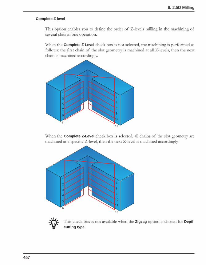
457
6. 2.5D Milling
Complete Z-level
This option enables you to define the order of Z-levels milling in the machining of several slots in one operation.
When the Complete Z-Level check box is not selected, the machining is performed as follows: the first chain of the slot geometry is machined at all Z-levels, then the next chain is machined accordingly.
When the Complete Z-Level check box is selected, all chains of the slot geometry are machined at a specific Z-level, then the next Z-level is machined accordingly.
This check box is not available when the Zigzag option is chosen for Depth cutting type.
172839410
511
612
12345678
910
1112

458
Section depth type
When you click on the Data button, the Section Slot Data dialog box is displayed.
Section geometry name
The section specifies the depth profile for this slot operation. As the geometry for this 2.5D operation is designed using 2D profiles and sections, a reference point is required to indicate the position of the Upper level.
Section data
• Scallop
This value determines the quality of the resulting surface on the floor of the slot. The smaller the value, the smoother is the surface.
• Descent Angle
The tool plunges into the material with the given ramp angle. The default value of 90 degrees causes a normal approach into the material. The tool enters the material at an angle to the first slot profile. If the tool path length required to perform the ramp angle is longer than the slot profile, SolidCAM generates a zigzag movement to plunge into the material.
Rough, Semi-finish and Finish cycles
• Roughcycle
If you check this option, the rough operation clears the slot before the semi-finish operation is performed.
Reference point (Upper Level)
Section(Depth profile)
Slot Geometry

459
6. 2.5D Milling
Enter the Step down between two successive cuts during roughing.
Define the offset that remains on the slot walls and floor after the roughing cut in the Rough/Semi-finish offset field.
• Finishcycle
Check this option if you intend to semi-finish and/or finish the slot. Choose the cycles you want to perform from the list.
• Semi-finish: the slot is machined at the offset specified in the Rough/Semi-finish offset field.
• Finish: the slot is machined to its final dimensions and specified surface scallop.
• Both: the slot is machined first with a semi-finish and then a finishing cut.
Offset for Rough/Semi-finish
This value specifies the offset that remains on the slot after the rough and semi-finish operations. This offset is removed in the last finish cut.
Technology
• Toolside
Specify the side of the slot profile at which you want to mill. The tool side is always relative to the direction of the slot‘s chain geometry.
• Right: the tool machines on the right side of the slot geometry. The cut leaves material on the profile equal to the specified Offset on profile value.
• Left: the tool machines on the left side of the slot geometry. The cut leaves material on the profile equal to the specified Offset on profile value.
• Center: the center of the tool moves on the profile geometry.
When the Zigzag option is used, the Tool side combo-box defines the tool location for the first cut. For each successive cutting pass, the tool position is changed relative to the geometry direction.

460
With additional parameters for the right and left extension, the Center option enables you to machine slots that are wider than the tool diameter. The given side step value is used to cut from the right to the left side. Note that the side definition is always relative to the direction of the slot profile. Check the direction of the profile by clicking on the Show button in the Section Geometry name area of the Slot Operation dialog box.
• Right extension: enter the distance by which the slot is extended to the right side (relative to profile direction).
• Left extension: enter the distance by which the slot is extended to the left side (relative to profile direction).
• Side step: enter the tool’s side step in successive tool paths.
Cutting direction
• The One way option enables you to create the tool path with only one-directional movements.
• The Zigzag option enables you to create the tool path with bi-directional movements.
Zigzag One way
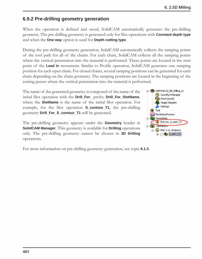
461
6. 2.5D Milling
6.9.2 Pre-drilling geometry generation
When the operation is defined and saved, SolidCAM automatically generates the pre-drilling geometry. The pre-drilling geometry is generated only for Slot operations with Constant depth type and when the One way option is used for Depth cutting type.
During the pre-drilling geometry generation, SolidCAM automatically collects the ramping points of the tool path for all of the chains. For each chain, SolidCAM collects all the ramping points where the vertical penetration into the material is performed. These points are located in the start point of the Lead in movement. Similar to Profile operation, SolidCAM generates one ramping position for each open chain. For closed chains, several ramping positions can be generated for each chain depending on the chain geometry. The ramping positions are located in the beginning of the cutting passes where the vertical penetration into the material is performed.
The name of the generated geometry is composed of the name of the initial Slot operation with the Drill_For_ prefix: Drill_For_SlotName, where the SlotName is the name of the initial Slot operation. For example, for the Slot operation S_contour_T1, the pre-drilling geometry Drill_For_S_contour_T1 will be generated.
The pre-drilling geometry appears under the Geometry header in SolidCAM Manager. This geometry is available for Drilling operations only. The pre-drilling geometry cannot be chosen in 3D Drilling operations.
For more information on pre-drilling geometry generation, see topic 6.1.3.

462
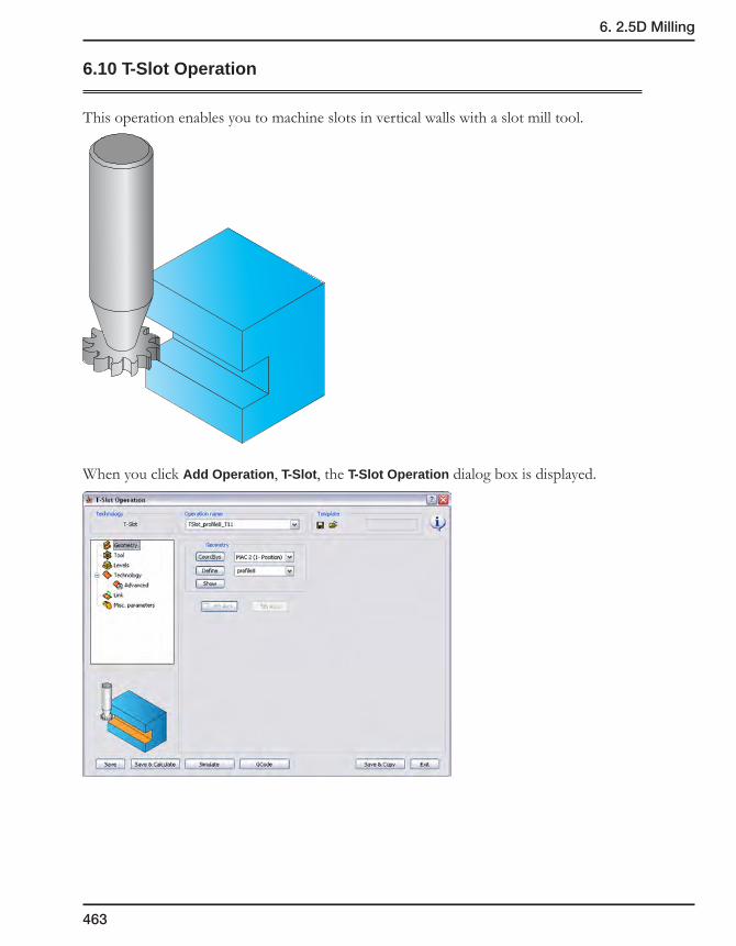
463
6. 2.5D Milling
6.10 T-Slot Operation
This operation enables you to machine slots in vertical walls with a slot mill tool.
When you click Add Operation, T-Slot, the T-Slot Operation dialog box is displayed.

464
6.10.1 Tool page
Tool data definition
The Data button displays the Operation Tool Data dialog box. This dialog box displays the tool material, feed and speed parameters and the diameter and length offset numbers used in the current operation.
The Second offset number parameter defines the register number of the upper cutting face offset, in the offset table of the CNC-machine. This option enables SolidCAM to automatically take into account the minor size differences between the defined tool and the one actually used for cutting the workpiece, if there are any. You may choose not to use this option by clearing the check box.
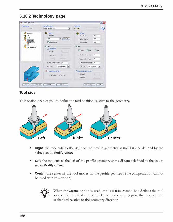
465
6. 2.5D Milling
6.10.2 Technology page
Tool side
This option enables you to define the tool position relative to the geometry.
• Right: the tool cuts to the right of the profile geometry at the distance defined by the values set in Modify offset.
• Left: the tool cuts to the left of the profile geometry at the distance defined by the values set in Modify offset.
• Center: the center of the tool moves on the profile geometry (the compensation cannot be used with this option).
When the Zigzag option is used, the Tool side combo-box defines the tool location for the first cut. For each successive cutting pass, the tool position is changed relative to the geometry direction.
Left Right Center

466
Geometry
This button enables you to modify a geometry shared by several operations separately for each operation.
Compensation
If the Compensation check box is selected, the tool radius compensation options G4x of the CNC-controller are used in the GCode.
For more information, see topic 6.1.2.
Offsets
To perform the rough machining of the slot, you have to specify various offsets on the slot geometry.
• Wall offset
This option defines the offset that will remain on the slot wall after roughing.
• Ceiling offset
This option defines the offset that will remain on the slot ceiling after roughing.
Ceilingoffset
Wall offset

467
6. 2.5D Milling
• Floor offset
This option defines the offset that will remain on the slot floor after roughing.
Depth cutting type
When the One way option is chosen, the cutting passes are oriented in the same direction and connection between them is performed through the Operation Clearance level. At the end of each pass the tool performs a retreat movement to the Operation Clearance level, a horizontal movement at rapid feed to the start point of the next pass and then descends to the Z-level of the next pass. The same cutting direction (climb or conventional) is kept along the whole tool path.
When the Zigzag option is chosen, the tool path is performed in a zigzag manner, with the tool path direction changing from one pass to the next. The passes located at two successive Z-levels are connected directly from the end of one pass to the beginning of the next pass.
The Zigzag option cannot be used together with the Clear offset technology.
Fillet size for last cut
This option enables you to add a radius to a sharp corner without changing the geometry.
For more information on this option, see topic 6.1.2.
Flooroffset

468
Rough
This section enables you to perform the rough machining of the slot.
Clear offset
This option generates several concentric profiles with constant depth that start at the defined clear offset distance from the profile and finish at the geometry of the profile, thus clearing the area around the profile.
The Offset option defines the distance from the geometry at which the milling starts. The Offset value must be equal to or greater than the Wall offset value. The tool starts milling the profile at the distance defined by Clear offset and finishes at the distance defined by Wall offset.
The Step over option defines the overlap of adjacent tool paths. It determines the offset between two successive concentric profiles.
• The Zigzag option enables you to create the tool path for the Clear offset removal containing both climb and conventional movements.
• The One way option enables you to create the tool path for the Clear offset removal containing only climb movements.
Clear offset
Modify offset
Walloffset
Step over
Clear offsettool path
Profilegeometry
Clear offsettool path
Profilegeometry
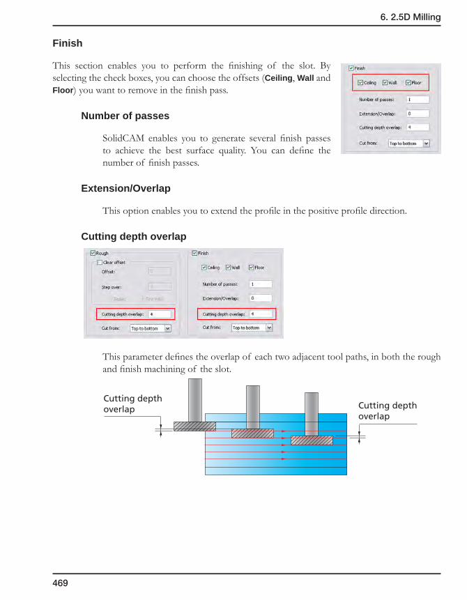
469
6. 2.5D Milling
Finish
This section enables you to perform the finishing of the slot. By selecting the check boxes, you can choose the offsets (Ceiling, Wall and Floor) you want to remove in the finish pass.
Number of passes
SolidCAM enables you to generate several finish passes to achieve the best surface quality. You can define the number of finish passes.
Extension/Overlap
This option enables you to extend the profile in the positive profile direction.
Cutting depth overlap
This parameter defines the overlap of each two adjacent tool paths, in both the rough and finish machining of the slot.
Cutting depthoverlap
Cutting depthoverlap

470
Cut from
This option enables you to define the direction of machining. The rough and finish machining of the slot can be performed in the following directions:
• Toptobottom
• Bottomtotop
• Middletobottom
• Middletotop
6.10.3 Link page
Ramping
This section determines how the tool approaches the start point of the contour.
For more information on Ramping options, see topic 6.1.3.
Lead in/Lead out
These options enable you to control the way the tool approaches and retreats from the profile.
For more information on Lead in/Lead out options, see topic 6.1.3.
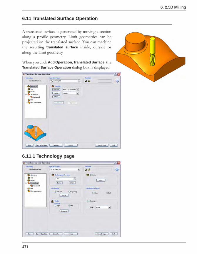
471
6. 2.5D Milling
6.11 Translated Surface Operation
A translated surface is generated by moving a section along a profile geometry. Limit geometries can be projected on the translated surface. You can machine the resulting translated surface inside, outside or along the limit geometry.
When you click Add Operation, Translated Surface, the Translated Surface Operation dialog box is displayed.
6.11.1 Technology page

472
Section geometry name
A translated surface requires two geometries: the profile along which the section is translated and the section geometry.
The geometries in this example result in the following translated surface:
For detailed explanation of section geometry definition, see topic 4.4.4.
Process type
The Translated Surface operation can be used to mill surfaces and also to engrave profiles, such as text, on a translated surface.
To engrave a profile on a translated surface, use the Translated Surface operation that you used to mill the surface as a template. Click Add Operation, Translated Surface and select the original Translated Surface operation from the Operation name list in the operation dialog box. All the geometries and parameters of the original operation are copied.
Choose the Process type and click on the Data button to define additional parameters.
Section Geometry
ProfileGeometry
Translated SurfaceProcess Type
Surface Engraving
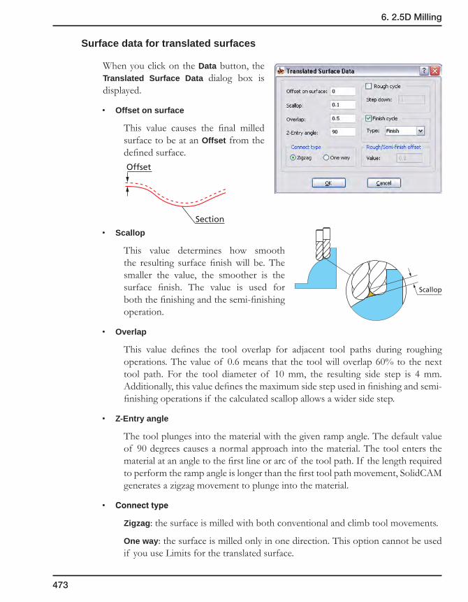
473
6. 2.5D Milling
Surface data for translated surfaces
When you click on the Data button, the Translated Surface Data dialog box is displayed.
• Offset on surface
This value causes the final milled surface to be at an Offset from the defined surface.
• Scallop
This value determines how smooth the resulting surface finish will be. The smaller the value, the smoother is the surface finish. The value is used for both the finishing and the semi-finishing operation.
• Overlap
This value defines the tool overlap for adjacent tool paths during roughing operations. The value of 0.6 means that the tool will overlap 60% to the next tool path. For the tool diameter of 10 mm, the resulting side step is 4 mm. Additionally, this value defines the maximum side step used in finishing and semi-finishing operations if the calculated scallop allows a wider side step.
• Z-Entry angle
The tool plunges into the material with the given ramp angle. The default value of 90 degrees causes a normal approach into the material. The tool enters the material at an angle to the first line or arc of the tool path. If the length required to perform the ramp angle is longer than the first tool path movement, SolidCAM generates a zigzag movement to plunge into the material.
• Connecttype
Zigzag: the surface is milled with both conventional and climb tool movements.
One way: the surface is milled only in one direction. This option cannot be used if you use Limits for the translated surface.
Offset
Section
Scallop
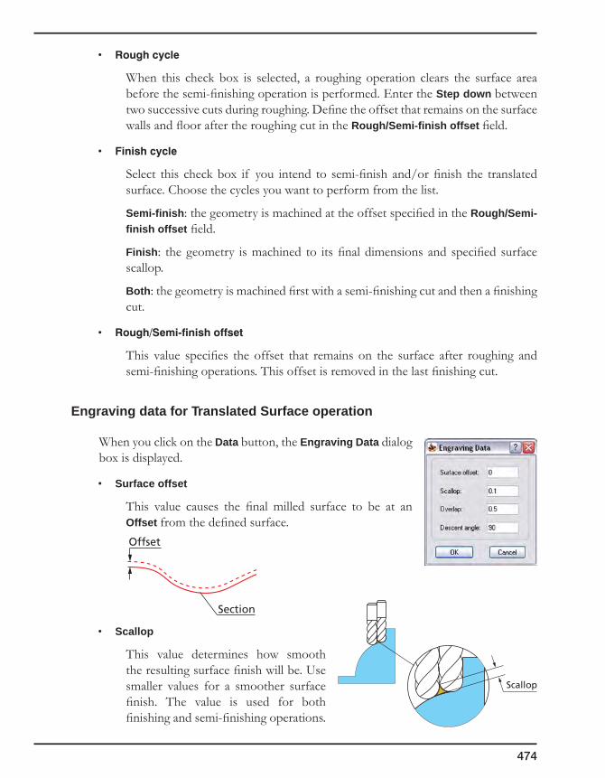
474
• Roughcycle
When this check box is selected, a roughing operation clears the surface area before the semi-finishing operation is performed. Enter the Step down between two successive cuts during roughing. Define the offset that remains on the surface walls and floor after the roughing cut in the Rough/Semi-finish offset field.
• Finishcycle
Select this check box if you intend to semi-finish and/or finish the translated surface. Choose the cycles you want to perform from the list.
Semi-finish: the geometry is machined at the offset specified in the Rough/Semi-finish offset field.
Finish: the geometry is machined to its final dimensions and specified surface scallop.
Both: the geometry is machined first with a semi-finishing cut and then a finishing cut.
• Rough/Semi-finishoffset
This value specifies the offset that remains on the surface after roughing and semi-finishing operations. This offset is removed in the last finishing cut.
Engraving data for Translated Surface operation
When you click on the Data button, the Engraving Data dialog box is displayed.
• Surface offset
This value causes the final milled surface to be at an Offset from the defined surface.
• Scallop
This value determines how smooth the resulting surface finish will be. Use smaller values for a smoother surface finish. The value is used for both finishing and semi-finishing operations.
Offset
Section
Scallop

475
6. 2.5D Milling
• Overlap
This value defines the tool overlap for adjacent tool paths during roughing operations. The value of 0.6 means that the tool will overlap 60% to the next tool path. For a tool diameter of 10 mm, the resulting a side step is 4 mm. Additionally, this value defines the maximum side step used in semi-finishing and finishing operations if the calculated scallop allows a wider side step.
• Descent angle
The tool plunges into the material with the given ramp angle. The default value of 90 degrees causes a normal approach into the material. The tool enters the material at an angle to the first line or arc of the tool path. If the length required to perform the ramp angle is longer than the first tool path movement, SolidCAM generates a zigzag movement to plunge into the material.
Tool side
This option determines on which side of the profile the section is machined. Use the Show surface button to display the current tool position relative to the profile geometry.
The geometry direction set in the Reverse geometry field also affects the tool side option.
• Right: the tool path is generated on the right side of the profile geometry.
• Left: the tool path is generated on the left side of the profile geometry.
The Geometry button displays the Modify Geometry dialog box that enables you to modify a geometry shared by several operations separately for each operation (see topic 6.1.2).
Limits
A limit is a profile geometry that can be used to define additional 2D profiles on the surface and to exclude areas on the surface from machining. If you would like to use a limit on your translated surface, select the Limits check box and click on the Data button. To use the Engraving process type, you must specify the Engraving geometry and additional parameters in the Engraving Profile dialog box.
Translated SurfaceLimit Type
Surface Engraving

476
Limit data for translated surface
When you click on the Data button, the Surface Limit dialog box is displayed.
The geometries in the example result in the following translated surface with limits:
• Limitgeometryname
In this section, specify which contour, i.e. profile geometry you want to use as the Limit. Note that the Limit geometry must be closed.
• Machiningarea
Outside Limit geometry: the area of the translated surface outside the limit is machined.
Inside Limit geometry: only the area inside of the limit geometries is machined.
Profile
Section Profile
Limit

477
6. 2.5D Milling
• OffsetonLimitgeometry
After machining, the CAM-Part has remaining material on the limit geometry equal to this value.
• FinishonLimit
Select this check box if you intend to semi-finish and/or finish the limits on the translated surface. Use the lists to choose the cycles you want to perform.
Type
• The Finish option machines the limit to its final dimensions in one step down.
• The Semi-finish option prepares the limits to an offset specified in the Offset field with a cutting depth defined in the Step down field.
• The Both option machines the limit first with a semi-finish cut and then with a finishing cut.
Side
If the Limit geometry is composed of one or more chains, but neither is placed inside another chain, the default option Both should be used. SolidCAM will then use the relevant finish side depending on whether the Limit type is Outside or Inside.
In this example, the Limit geometry contains a chain inside another chain (Chain #2 inside Chain #1) and a separate limit Chain #3.
• The External option finishes all outside contours of the Limit chains, leaving the inside hole unfinished.
12 3
Finish cuts

478
• The Internal option finishes only the inside contour of the Limit chain, leaving the outside Limit contours unfinished.
• The Both option finishes all inside and outside contours of the Limit chains.
Cutting direction
This field defines the cutting direction on the last finish cut. It can be either clockwise (CW) or counterclockwise (CCW).
Semi-finish offset
Enter the offset that will remain on the surface after the semi-finish operation. This offset will be removed in a last cut, if a finish cut has been specified.
Semi-finish Step down
The step down defines the cutting depth of the tool on the Limit geometries used for the semi-finishing operation.
Finish cuts
Finish cuts
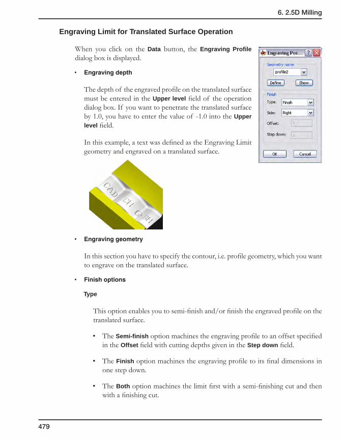
479
6. 2.5D Milling
Engraving Limit for Translated Surface Operation
When you click on the Data button, the Engraving Profile dialog box is displayed.
• Engravingdepth
The depth of the engraved profile on the translated surface must be entered in the Upper level field of the operation dialog box. If you want to penetrate the translated surface by 1.0, you have to enter the value of -1.0 into the Upper level field.
In this example, a text was defined as the Engraving Limit geometry and engraved on a translated surface.
• Engravinggeometry
In this section you have to specify the contour, i.e. profile geometry, which you want to engrave on the translated surface.
• Finishoptions
Type
This option enables you to semi-finish and/or finish the engraved profile on the translated surface.
• The Semi-finish option machines the engraving profile to an offset specified in the Offset field with cutting depths given in the Step down field.
• The Finish option machines the engraving profile to its final dimensions in one step down.
• The Both option machines the limit first with a semi-finishing cut and then with a finishing cut.
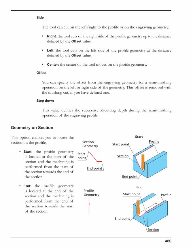
480
Side
The tool can cut on the left/right to the profile or on the engraving geometry.
• Right: the tool cuts on the right side of the profile geometry up to the distance defined by the Offset value.
• Left: the tool cuts on the left side of the profile geometry at the distance defined by the Offset value.
• Center: the center of the tool moves on the profile geometry.
Offset
You can specify the offset from the engraving geometry for a semi-finishing operation on the left or right side of the geometry. This offset is removed with the finishing cut, if you have defined one.
Step down
This value defines the successive Z-cutting depth during the semi-finishing operation of the engraving profile.
Geometry on Section
This option enables you to locate the section on the profile.
• Start: the profile geometry is located at the start of the section and the machining is performed from the start of the section towards the end of the section.
• End: the profile geometry is located at the end of the section and the machining is performed from the end of the section towards the start of the section.
SectionGeometry
Section
ProfileStart point
Start
End
End point
ProfileGeometry
Startpoint
End point
Section
ProfileStart point
End point
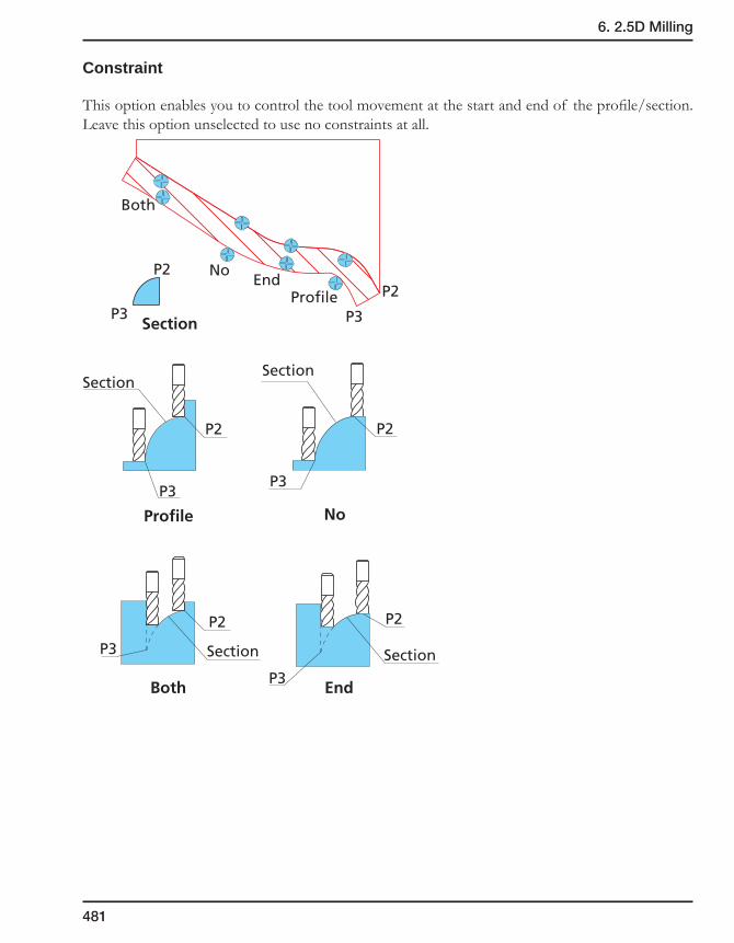
481
6. 2.5D Milling
Constraint
This option enables you to control the tool movement at the start and end of the profile/section. Leave this option unselected to use no constraints at all.
P2P2
Both
Both
No
No
End
End
Profile
Profile
P3 P3
P2
P3
P2
P3
P2
P3
P2
P3
Section
Section
Section
Section
Section

482
6.11.2 Link page
Lead in/Lead out
You can control the way the tool leads in to/out from the geometry. Choose an option from the list and enter the distance value for this option.
SolidCAM enables you to use the following Lead in/Lead out options:
• None
• Normal
• Arc
• Tangent
• Point
For more information on this subject, see topic 6.1.3.

3D Milling 7SolidCAM 3D Milling can be used for both prismatic parts and complex 3D models. For prismatic parts, SolidCAM analyzes the model and automatically recognizes pockets and profiles to be machined using Z-constant machining strategies.
For molds, electrodes and prototypes, SolidCAM offers powerful 3D machining, including advanced High Speed Machining strategies and integrated rest material options. No matter how complex is the model, SolidCAM provides the optimal approach and roughing strategy with superior 3D finish machining for mold and die applications.
3D Milling Operation
Roughing strategies
Semi-finishing & Finishing strategies
3D Engraving Operation
3D Drilling Operation
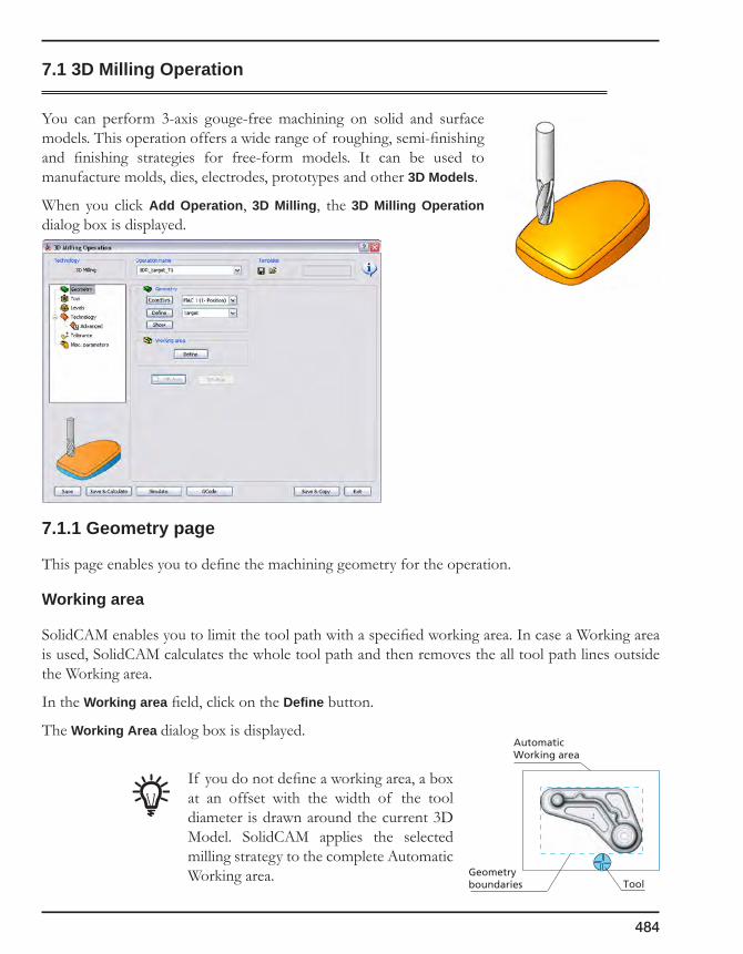
484
7.1 3D Milling Operation
You can perform 3-axis gouge-free machining on solid and surface models. This operation offers a wide range of roughing, semi-finishing and finishing strategies for free-form models. It can be used to manufacture molds, dies, electrodes, prototypes and other 3D Models.
When you click Add Operation, 3D Milling, the 3D Milling Operation dialog box is displayed.
7.1.1 Geometry page
This page enables you to define the machining geometry for the operation.
Working area
SolidCAM enables you to limit the tool path with a specified working area. In case a Working area is used, SolidCAM calculates the whole tool path and then removes the all tool path lines outside the Working area.
In the Working area field, click on the Define button.
The Working Area dialog box is displayed.
If you do not define a working area, a box at an offset with the width of the tool diameter is drawn around the current 3D Model. SolidCAM applies the selected milling strategy to the complete Automatic Working area. Geometry
boundaries
AutomaticWorking area
Tool

7. 3D Milling
485
The Working Area dialog box enables you to choose the type of working area and set the related parameters.
The working area can be defined using one or a combination of the following methods:
The resulting working area boundary is generated as a boolean combination of the following:
• User-defined planar geometry with an offset;
• Selected drive surfaces;
• Selected check surfaces with an offset;
• Surface angle minimum and maximum limits.
The generated working area boundary is then used either for tool path generation (e.g. Circular pocket, Constant Step over, etc.) or as a boundary to trim the tool path (Linear, Pencil milling, etc.).
Working area definition via Geometry
In this section, you have to specify the working area geometry that defines the machining boundaries for the operation.
If you have already defined working area geometries for this CAM-Part, you can choose the geometry from the Name list.
• The Show button displays the chosen geometry in the SolidWorks window.
• The Define button enables you to select a new working area geometry.
For more information on Geometry selection, see topic 4.4.1.
Working area Working area geometry
Angle limits
Selected faces
Rest material

486
Working area definition via Rest material
With the Cut only in rest material option, you can limit the machining to the rest material.
Rest material is what has to be machined after the previous operations in order to reach the Target model. When the Cut only the Rest material option is chosen for the Working area definition, SolidCAM calculates the Updated Stock model (USM) after all the previous operations. SolidCAM automatically compares the USM with the target model and generates the rest material areas.
The rest material left after semi-finishing operations with a big tool Working only in the rest material area
This option is available only if the target model is defined.
• Mach.StockName
This option enables you to use the previously generated USM for the rest material calculation.
This field is available only when the Manual method of Updated Stock model calculation is used.
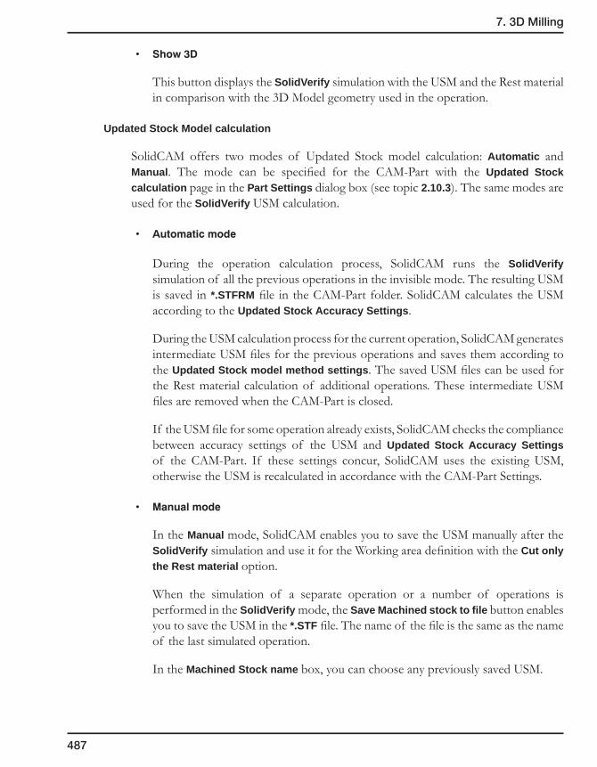
7. 3D Milling
487
• Show3D
This button displays the SolidVerify simulation with the USM and the Rest material in comparison with the 3D Model geometry used in the operation.
Updated Stock Model calculation
SolidCAM offers two modes of Updated Stock model calculation: Automatic and Manual. The mode can be specified for the CAM-Part with the Updated Stock calculation page in the Part Settings dialog box (see topic 2.10.3). The same modes are used for the SolidVerify USM calculation.
• Automaticmode
During the operation calculation process, SolidCAM runs the SolidVerify simulation of all the previous operations in the invisible mode. The resulting USM is saved in *.STFRM file in the CAM-Part folder. SolidCAM calculates the USM according to the Updated Stock Accuracy Settings.
During the USM calculation process for the current operation, SolidCAM generates intermediate USM files for the previous operations and saves them according to the Updated Stock model method settings. The saved USM files can be used for the Rest material calculation of additional operations. These intermediate USM files are removed when the CAM-Part is closed.
If the USM file for some operation already exists, SolidCAM checks the compliance between accuracy settings of the USM and Updated Stock Accuracy Settings of the CAM-Part. If these settings concur, SolidCAM uses the existing USM, otherwise the USM is recalculated in accordance with the CAM-Part Settings.
• Manualmode
In the Manual mode, SolidCAM enables you to save the USM manually after the SolidVerify simulation and use it for the Working area definition with the Cut only the Rest material option.
When the simulation of a separate operation or a number of operations is performed in the SolidVerify mode, the Save Machined stock to file button enables you to save the USM in the *.STF file. The name of the file is the same as the name of the last simulated operation.
In the Machined Stock name box, you can choose any previously saved USM.
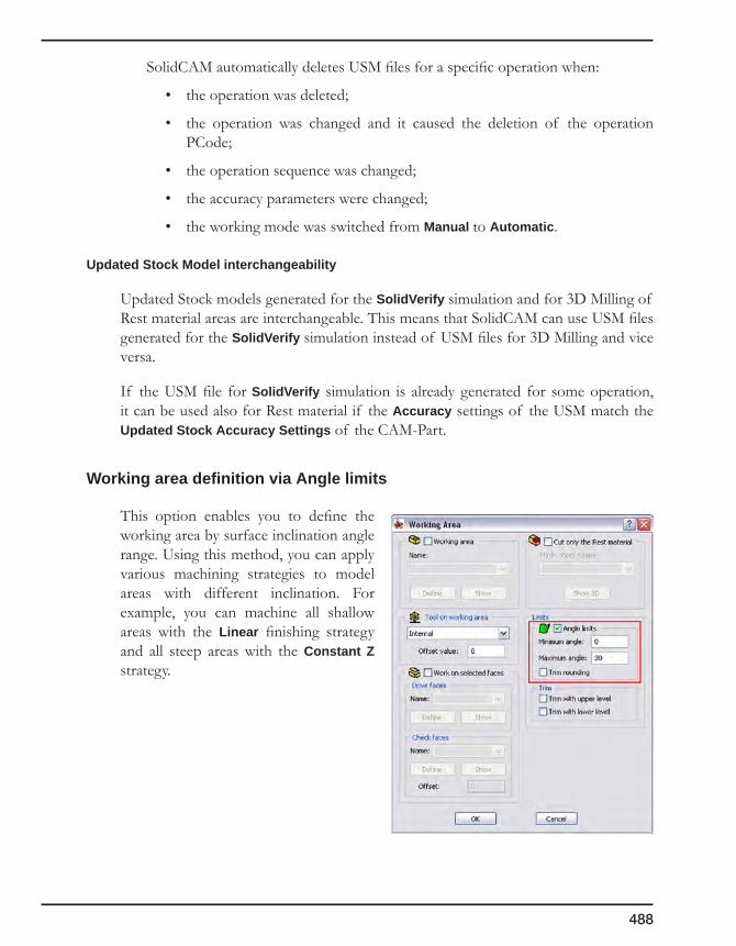
488
SolidCAM automatically deletes USM files for a specific operation when:
• the operation was deleted;
• the operation was changed and it caused the deletion of the operation PCode;
• the operation sequence was changed;
• the accuracy parameters were changed;
• the working mode was switched from Manual to Automatic.
Updated Stock Model interchangeability
Updated Stock models generated for the SolidVerify simulation and for 3D Milling of Rest material areas are interchangeable. This means that SolidCAM can use USM files generated for the SolidVerify simulation instead of USM files for 3D Milling and vice versa.
If the USM file for SolidVerify simulation is already generated for some operation, it can be used also for Rest material if the Accuracy settings of the USM match the Updated Stock Accuracy Settings of the CAM-Part.
Working area definition via Angle limits
This option enables you to define the working area by surface inclination angle range. Using this method, you can apply various machining strategies to model areas with different inclination. For example, you can machine all shallow areas with the Linear finishing strategy and all steep areas with the Constant Z strategy.
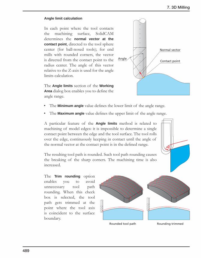
7. 3D Milling
489
Angle limit calculation
In each point where the tool contacts the machining surface, SolidCAM determines the normal vector at the contact point, directed to the tool sphere center (for ball-nosed tools); for end mills with rounded corners, the vector is directed from the contact point to the radius center. The angle of this vector relative to the Z-axis is used for the angle limits calculation.
The Angle limits section of the Working Area dialog box enables you to define the angle range.
• The Minimum angle value defines the lower limit of the angle range.
• The Maximum angle value defines the upper limit of the angle range.
A particular feature of the Angle limits method is related to machining of model edges: it is impossible to determine a single contact point between the edge and the tool surface. The tool rolls over the edge, continuously keeping in contact until the angle of the normal vector at the contact point is in the defined range.
The resulting tool path is rounded. Such tool path rounding causes the breaking of the sharp corners. The machining time is also increased.
The Trim rounding option enables you to avoid unnecessary tool path rounding. When this check box is selected, the tool path gets trimmed at the point where the tool axis is coincident to the surface boundary.
Normal vector
AngleContact point
Rounding trimmedRounded tool path

490
Working area definition via Face selection
You can define the area of the 3D Model machining with two sets of model faces:
• Drive faces – the set of faces to be milled. The tool path is generated only for machining of these faces.
• Check faces – the set of faces to be avoided during the generation of the tool path.
Other faces of the model are not considered during the tool path calculation.
Example: for the model shown above, SolidCAM generates the tool path only for the shallow area. During the calculation, gouging of the check faces is avoided. The remaining faces do not participate in the tool path calculation.
The above capability is available through the Work on selected faces area in the Working area dialog box.
Drive faces
Specify the Face geometry for Drive faces. If you have already defined such geometries for this CAM-Part, you can choose the geometry from the Name list.
• The Define button enables you to define a new Face geometry with the Select Faces dialog box.
• The Show button displays the Face geometry on the SolidWorks model.
Check faces
Specify the Face geometry for Check faces. If you have already defined such geometries for this CAM-Part, you can choose the geometry from the Name list.
• The Define button enables you to define a new Face geometry with the Select Faces dialog box.
• The Show button displays the Face geometry on the SolidWorks model.
Drive faces
Check faces
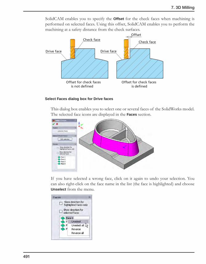
7. 3D Milling
491
SolidCAM enables you to specify the Offset for the check faces when machining is performed on selected faces. Using this offset, SolidCAM enables you to perform the machining at a safety distance from the check surfaces.
Select Faces dialog box for Drive faces
This dialog box enables you to select one or several faces of the SolidWorks model. The selected face icons are displayed in the Faces section.
If you have selected a wrong face, click on it again to undo your selection. You can also right-click on the face name in the list (the face is highlighted) and choose Unselect from the menu.
Check face
Drive face
Check face
Offset
Drive face
Offset for check faces is not defined
Offset for check faces is defined

492
• SelectCheckfaces
The CAD selection option enables you to select faces with the SolidWorks tools.
• Faces
This section enables you to display and edit the normals of model surfaces during the geometry selection.
The Show Direction for highlighted faces only check box enables you to display the surface normals for the specific highlighted faces in the faces list.
The Show Direction for selected faces check box enables you to display the normals direction for all the faces in the list.
The right-click menu available on the items in the Faces list enables you to reverse the direction of the surface normals of the chosen faces (the Reverse command) or of all the selected faces (the Reverse all command).

7. 3D Milling
493
Select faces dialog box for Check faces
This dialog box enables you to select one or several check faces of the SolidWorks model. The selected face icons are displayed in the Faces section.
If you have selected a wrong face, click on it again to undo your selection. You can also right-click on the face name in the list (the face is highlighted) and choose Unselect from the menu.
• SelectCheckfaces
The CAD Selection option enables you to select faces with the SolidWorks tools.
The All facesadjacenttodrivefacesbutton automatically adds all the model faces adjacent to the defined Drive faces to the selection list.
• Faces
This section enables you to display and edit the normals of model surfaces during the geometry selection.
Tool on working area
This option controls the tool position relative to the boundaries of the working area. Since the working area geometry is always projected on a 2D plane, viewing the model and working area in the top view shows exactly till where the tool machines the model.
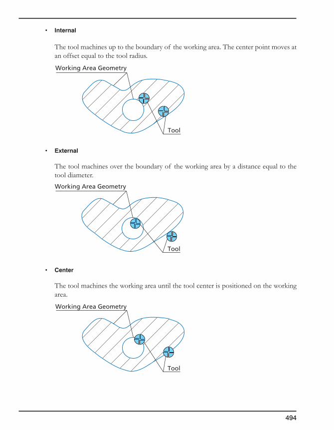
494
• Internal
The tool machines up to the boundary of the working area. The center point moves at an offset equal to the tool radius.
• External
The tool machines over the boundary of the working area by a distance equal to the tool diameter.
• Center
The tool machines the working area until the tool center is positioned on the working area.
Working Area Geometry
Tool
Working Area Geometry
Tool
Working Area Geometry
Tool
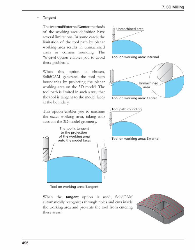
7. 3D Milling
495
• Tangent
The Internal/External/Center methods of the working area definition have several limitations. In some cases, the limitation of the tool path by planar working area results in unmachined areas or corners rounding. The Tangent option enables you to avoid these problems.
When this option is chosen, SolidCAM generates the tool path boundaries by projecting the planar working area on the 3D model. The tool path is limited in such a way that the tool is tangent to the model faces at the boundary.
This option enables you to machine the exact working area, taking into account the 3D model geometry.
When the Tangent option is used, SolidCAM automatically recognizes through holes and cuts inside the working area and prevents the tool from entering these areas.
Unmachined area
Tool on working area: Center
Unmachined area
Tool on working area: Internal
Tool on working area: External
Tool path rounding
Tool on working area: Tangent
The tool is tangentto the projection
of the working areaonto the model faces

496
Offset value (+/-)
This value enables you to specify the offset of the tool center. A positive offset value enlarges the working area; a negative value reduces the working area to be machined.
• To stay away from a pocket’s wall, for example, you can use the Internal option with a small negative offset value.
• To prevent the tool from plunging down a straight wall of a block, you can use the Middle option with an offset smaller than the tool radius. Also, with the same result, you can use the External option with a small negative offset value.
Tool path trimming
When the tool path is generated by a projection strategy (Linear, Circular pocket, etc.), SolidCAM projects the planar pattern on the model. When there is no model geometry in the specific point of the pattern (e.g. holes in the model), the pattern is projected onto the virtual infinite XY-plane located at the Operation Lower level.
The Tool path trimming options enable you to trim unnecessary movements at the Operation Lower level and movements above the Operation Upper level.
+
+
-
-
Planar pattern
OperationLower level
OperationUpper level
Tool path
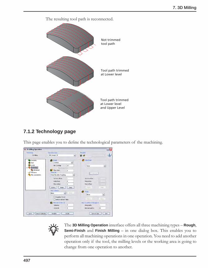
7. 3D Milling
497
The resulting tool path is reconnected.
7.1.2 Technology page
This page enables you to define the technological parameters of the machining.
The 3D Milling Operation interface offers all three machining types – Rough, Semi-Finish and Finish Milling – in one dialog box. This enables you to perform all machining operations in one operation. You need to add another operation only if the tool, the milling levels or the working area is going to change from one operation to another.
Not trimmedtool path
Tool path trimmed at Lower level
Tool path trimmed at Lower level and Upper Level
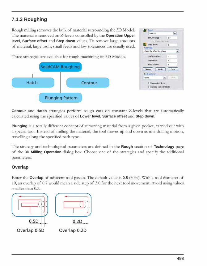
498
7.1.3 Roughing
Rough milling removes the bulk of material surrounding the 3D Model. The material is removed on Z-levels controlled by the Operation Upper level, Surface offset and Step down values. To remove large amounts of material, large tools, small feeds and low tolerances are usually used.
Three strategies are available for rough machining of 3D Models.
Contour and Hatch strategies perform rough cuts on constant Z-levels that are automatically calculated using the specified values of Lower level, Surface offset and Step down.
Plunging is a totally different concept of removing material from a given pocket, carried out with a special tool. Instead of milling the material, the tool moves up and down as in a drilling motion, travelling along the specified path type.
The strategy and technological parameters are defined in the Rough section of Technology page of the 3D Milling Operation dialog box. Choose one of the strategies and specify the additional parameters.
Overlap
Enter the Overlap of adjacent tool passes. The default value is 0.5 (50%). With a tool diameter of 10, an overlap of 0.7 would mean a side step of 3.0 for the next tool movement. Avoid using values smaller than 0.3.
SolidCAM Roughing
Plunging Pattern
Hatch Contour
0.5D
Overlap 0.5D
0.2D
Overlap 0.2D
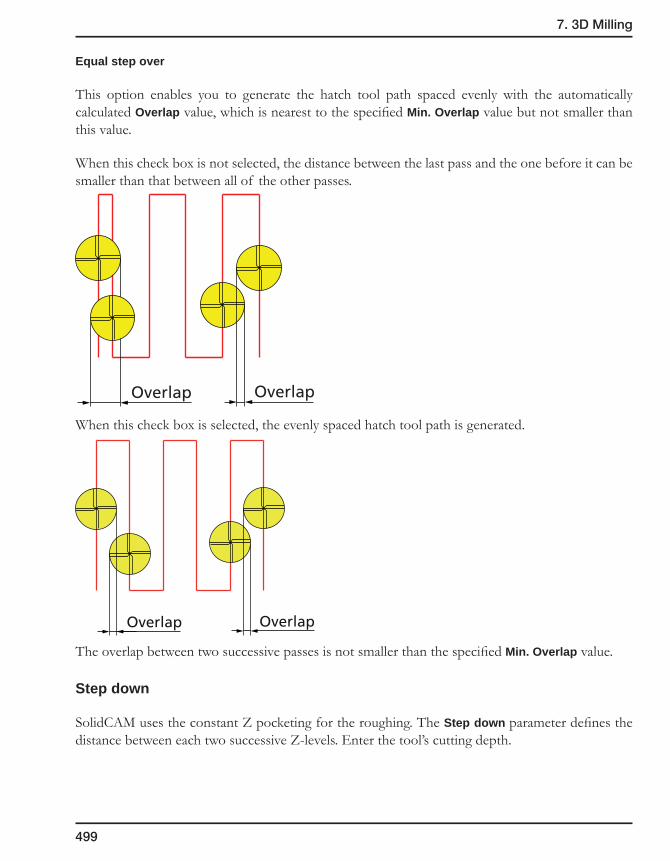
7. 3D Milling
499
Equal step over
This option enables you to generate the hatch tool path spaced evenly with the automatically calculated Overlap value, which is nearest to the specified Min. Overlap value but not smaller than this value.
When this check box is not selected, the distance between the last pass and the one before it can be smaller than that between all of the other passes.
When this check box is selected, the evenly spaced hatch tool path is generated.
The overlap between two successive passes is not smaller than the specified Min. Overlap value.
Step down
SolidCAM uses the constant Z pocketing for the roughing. The Step down parameter defines the distance between each two successive Z-levels. Enter the tool’s cutting depth.
OverlapOverlap
OverlapOverlap

500
Clean flat
SolidCAM generates a set of Z-levels with equal step down. Sometimes the model ledge with the specified offset falls between the Z-levels defined by Step down and cannot be machined in the current operation.
• None
When this option is chosen, the tool machines only at each step down distance. Anything in between is not machined.
• Cleanflatafterroughing
When this option is chosen, the tool performs complete roughing at each step down level and then returns to the flat areas between the step down levels.
• Cleanflatduringroughing
When this option is chosen, SolidCAM produces tool paths at the step down level. At this point, the tool machines the flat area located between the step down levels. After completing the flat area, it goes to the next step down.
Offsets
Surface offset is the minimum offset of material in the X-, Y- and Z-direction that remains on the model contour. The value defines the closest distance the tool can get to the model. The rough operation is performed at constant Z-levels.
In addition to the specified Surface offset, the roughed model shows stairs of rest material with a height equal to the Step down value. To obtain a uniform offset on the model, a semi-finish operation should be executed.
Not machined ledges between Z-Levels
Model withthe offset
Z-levels with the equal Step down
Model surface
Surface offset
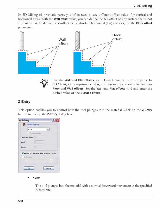
7. 3D Milling
501
In 3D Milling of prismatic parts, you often need to use different offset values for vertical and horizontal areas. With the Wall offset value, you can define the XY-offset of any surface that is not absolutely flat. To define the Z-offset to the absolute horizontal (flat) surfaces, use the Floor offset parameter.
Use the Wall and Flat offsets for 3D machining of prismatic parts. In 3D Milling of non-prismatic parts, it is best to use surface offset and not Floor and Wall offsets. Set the Wall and Flat offsets to 0 and enter the desired value of the Surface offset.
Z-Entry
This option enables you to control how the tool plunges into the material. Click on the Z-Entry button to display the Z-Entry dialog box.
• None
The tool plunges into the material with a normal downward movement at the specified Z-feed rate.
Walloffset
Flooroffset
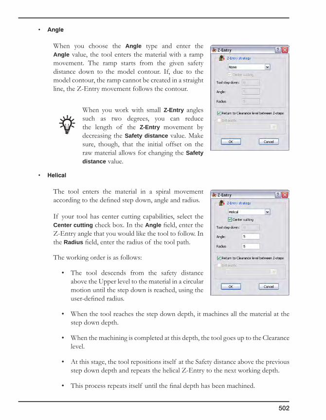
502
• Angle
When you choose the Angle type and enter the Angle value, the tool enters the material with a ramp movement. The ramp starts from the given safety distance down to the model contour. If, due to the model contour, the ramp cannot be created in a straight line, the Z-Entry movement follows the contour.
When you work with small Z-Entry angles such as two degrees, you can reduce the length of the Z-Entry movement by decreasing the Safety distance value. Make sure, though, that the initial offset on the raw material allows for changing the Safety distance value.
• Helical
The tool enters the material in a spiral movement according to the defined step down, angle and radius.
If your tool has center cutting capabilities, select the Center cutting check box. In the Angle field, enter the Z-Entry angle that you would like the tool to follow. In the Radius field, enter the radius of the tool path.
The working order is as follows:
• The tool descends from the safety distance above the Upper level to the material in a circular motion until the step down is reached, using the user-defined radius.
• When the tool reaches the step down depth, it machines all the material at the step down depth.
• When the machining is completed at this depth, the tool goes up to the Clearance level.
• At this stage, the tool repositions itself at the Safety distance above the previous step down depth and repeats the helical Z-Entry to the next working depth.
• This process repeats itself until the final depth has been machined.

7. 3D Milling
503
If the tool does not have center cutting capabilities, do not select the Center cutting check box. In the Tool step down field, enter the depth of the step down of the tool.
The result of this action is the same as that of the center cutting tool except for the following differences:
• The tool descends from the Safety distance above the Upper level to the material in a circular motion up to the Tool Step down.
• At this point, the tool clears the circular path. Then it descends to the next Tool Step down.
• This is repeated until the tool reaches the CAM-Part’s step down depth.
• When the tool reaches the step down depth, it machines all the material on that step down depth.
• When the machining is completed at this depth, the tool goes up to the Clearance level.
• At this stage, the tool repositions itself at the Safety distance above the previous step down depth and repeats the Helical Z-Entry to the next working depth.
• This process repeats itself until the final depth has been machined.
• Linear
The Linear Z-Entry follows the same rules as the Helical. The difference is that the Z-Entry is performed in a linear zigzag fashion rather than in a circular one.
If your tool has center cutting capabilities, select the Center cutting check box. In the Linear dialog box, enter the length of the linear tool path that you would like the tool to travel.
The working order is as follows:
• The tool descends from the Safety distance above the Upper level to the material in a zigzag motion based on the user defined angle and length until the step down is reached.
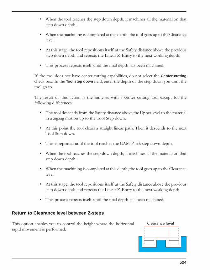
504
• When the tool reaches the step down depth, it machines all the material on that step down depth.
• When the machining is completed at this depth, the tool goes up to the Clearance level.
• At this stage, the tool repositions itself at the Safety distance above the previous step down depth and repeats the Linear Z-Entry to the next working depth.
• This process repeats itself until the final depth has been machined.
If the tool does not have center cutting capabilities, do not select the Center cutting check box. In the Tool step down field, enter the depth of the step down you want the tool go to.
The result of this action is the same as with a center cutting tool except for the following differences:
• The tool descends from the Safety distance above the Upper level to the material in a zigzag motion up to the Tool Step down.
• At this point the tool clears a straight linear path. Then it descends to the next Tool Step down.
• This is repeated until the tool reaches the CAM-Part’s step down depth.
• When the tool reaches the step down depth, it machines all the material on that step down depth.
• When the machining is completed at this depth, the tool goes up to the Clearance level.
• At this stage, the tool repositions itself at the Safety distance above the previous step down depth and repeats the Linear Z-Entry to the next working depth.
• This process repeats itself until the final depth has been machined.
Return to Clearance level between Z-steps
This option enables you to control the height where the horizontal rapid movement is performed.
Clearance level

7. 3D Milling
505
When this check box is selected (default), SolidCAM performs horizontal rapid movements at the Clearance level of the operation.
When this check box is not selected, SolidCAM performs horizontal rapid movements at the Safety distance from the last cut and checks for possible collisions. In areas where the rapid movements at the Safety distance causes gouges, SolidCAM performs the horizontal rapid movements at the Clearance level.
Drill points
SolidCAM enables you to perform the approach to the material from the hole previously machined in 3D Drilling operation (see topic 7.3). The 3D Drilling operation has to precede the 3D Milling operation in SolidCAM Manager. SolidCAM enables you to choose the geometry used for the 3D Drilling operation in order to define the approach point.
Mode (Open Pocket machining)
SolidCAM locates open pocket areas and enables you to machine them with a specific strategy. This strategy enables you to combine pocket and profile tool paths in order to provide the best productivity in open pocket machining.
The Open Pocket machining option is available to use in 3D Milling operation for Roughing and Constant Z Floor machining strategy (see topic 7.1.13).
The Mode button displays the Open pocket mode dialog box.
Clearance level
Safetydistance
Drill point
Material to beremoved
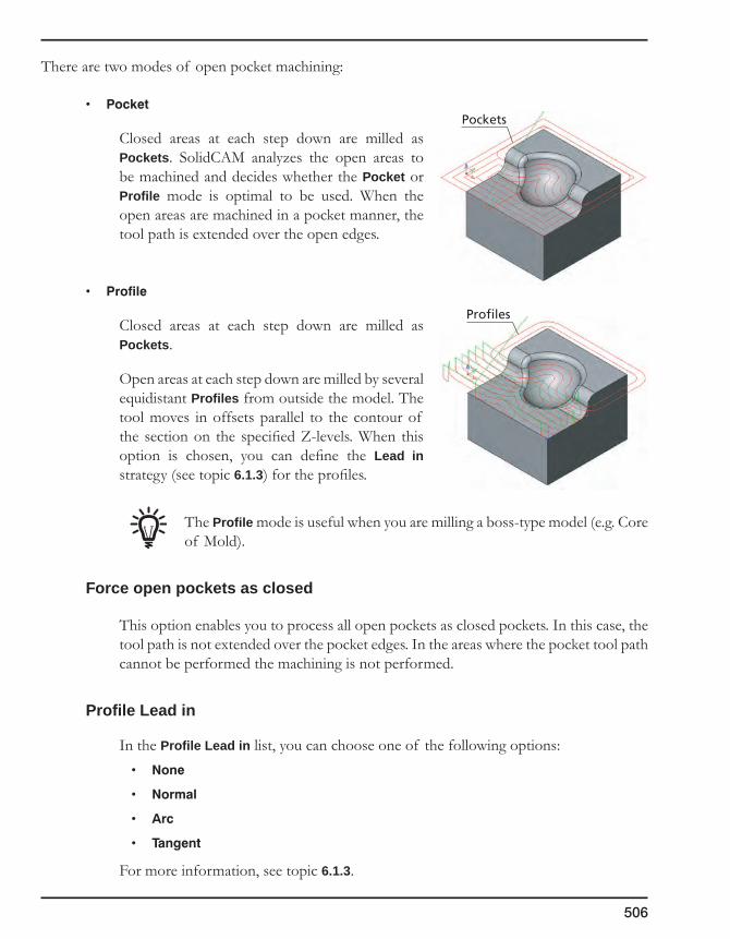
506
There are two modes of open pocket machining:
Closed areas at each step down are milled as Pockets. SolidCAM analyzes the open areas to be machined and decides whether the Pocket or Profile mode is optimal to be used. When the open areas are machined in a pocket manner, the tool path is extended over the open edges.
• Profile
Closed areas at each step down are milled as Pockets.
Open areas at each step down are milled by several equidistant Profiles from outside the model. The tool moves in offsets parallel to the contour of the section on the specified Z-levels. When this option is chosen, you can define the Lead in strategy (see topic 6.1.3) for the profiles.
The Profile mode is useful when you are milling a boss-type model (e.g. Core of Mold).
Force open pockets as closed
This option enables you to process all open pockets as closed pockets. In this case, the tool path is not extended over the pocket edges. In the areas where the pocket tool path cannot be performed the machining is not performed.
Profile Lead in
In the Profile Lead in list, you can choose one of the following options:• None
• Normal
• Arc
• Tangent
For more information, see topic 6.1.3.
Pockets
Profiles
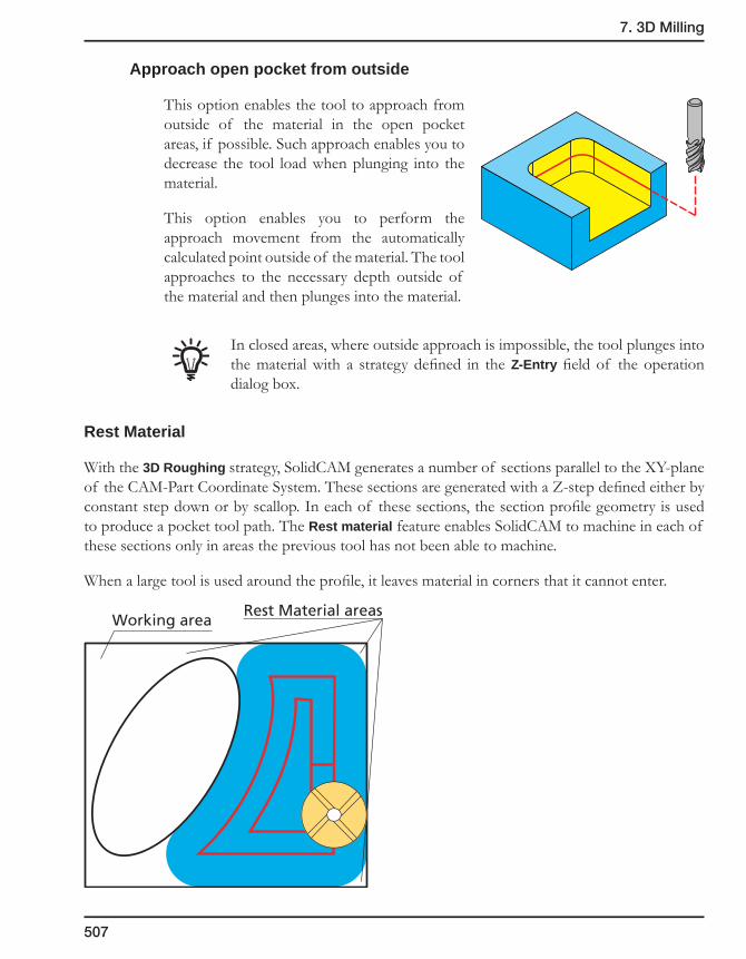
7. 3D Milling
507
Approach open pocket from outside
This option enables the tool to approach from outside of the material in the open pocket areas, if possible. Such approach enables you to decrease the tool load when plunging into the material.
This option enables you to perform the approach movement from the automatically calculated point outside of the material. The tool approaches to the necessary depth outside of the material and then plunges into the material.
In closed areas, where outside approach is impossible, the tool plunges into the material with a strategy defined in the Z-Entry field of the operation dialog box.
Rest Material
With the 3D Roughing strategy, SolidCAM generates a number of sections parallel to the XY-plane of the CAM-Part Coordinate System. These sections are generated with a Z-step defined either by constant step down or by scallop. In each of these sections, the section profile geometry is used to produce a pocket tool path. The Rest material feature enables SolidCAM to machine in each of these sections only in areas the previous tool has not been able to machine.
When a large tool is used around the profile, it leaves material in corners that it cannot enter.
Working areaRest Material areas

508
The Rest material option enables you to remove the material from this area without defining a new geometry.
The Rest Material dialog box is displayed.
In this dialog box, you have to define the following parameters:
• Previous tool diameter – the diameter of the rough end mill used in the previous operation.
• Previous wall offset – the wall offset of the previous operation.
• Extension – the overlap distance that you would like to start and end from the previous larger end mill.
Milling type
If you choose Separate areas, SolidCAM generates a profile or pocket tool path to clean areas that the previous tool could not mill. The Around profile strategy generates a closed profile to mill the rest material.
Separate areas: SolidCAM machines only the areas not machined with the previous tool.
Around Profile: SolidCAM machines the whole profile.
Rest MaterialExtension

7. 3D Milling
509
In 3D Milling and Pocket operations with the Separate areas machining strategy, SolidCAM generates two types of tool paths, depending on the volume of the rest material and on the previous and present tool diameters:
Pocket-style tool paths Profile-style tool paths
SolidCAM generates a pocket or a profile tool path in each area of the rest material.
Pocket-style tool path areas can be either open or closed depending on the approach possibilities.
The approach to the open pockets can be performed from the machined space in contrast to the closed pockets where the approach from the outside is unavailable.
Open pocket-style tool path area
Open pocket-styletool path area
Profile-style tool path area
Closed pocket-styletool path area
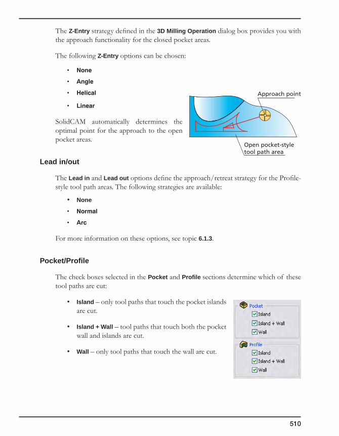
510
The Z-Entry strategy defined in the 3D Milling Operation dialog box provides you with the approach functionality for the closed pocket areas.
The following Z-Entry options can be chosen:
• None
• Angle
• Helical
• Linear
SolidCAM automatically determines the optimal point for the approach to the open pocket areas.
Lead in/out
The Lead in and Lead out options define the approach/retreat strategy for the Profile-style tool path areas. The following strategies are available:
• None
• Normal
• Arc
For more information on these options, see topic 6.1.3.
Pocket/Profile
The check boxes selected in the Pocket and Profile sections determine which of these tool paths are cut:
• Island – only tool paths that touch the pocket islands are cut.
• Island + Wall – tool paths that touch both the pocket wall and islands are cut.
• Wall – only tool paths that touch the wall are cut.
Open pocket-styletool path area
Approach point

7. 3D Milling
511
Compensation
When the Compensation dialog box is selected, tool radius compensation commands are used (G41, G42 for Fanuc) in GCode output.
Open contour strategy
This option enables you to define the direction of the open contours machining.
• Oneway
The tool moves along an open contour at a specific Z-level. At the end of the contour, the tool moves with rapid feed (G0) to the Safety distance and then starts machining the open contour at the next Z-level. The tool will always use climb or conventional milling.
• Zigzag
The tool finishes an open contour at the specific Z-level and then moves directly to the next Z-level and so on. It mills forward and backward without leaving the material, thus constantly switching between climb and conventional milling.
Complete Z-level
This option enables you to define the order of the machining Z-levels.
Consider the CAM-Part with two cavities that must be machined with 3D Milling: either with roughing strategies or with the Constant Z finishing strategy.
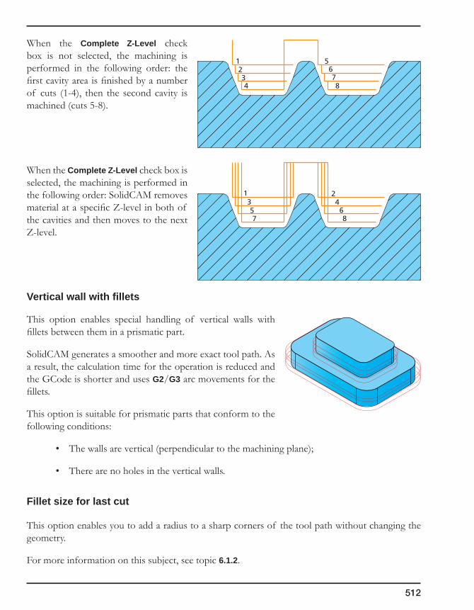
512
When the Complete Z-Level check box is not selected, the machining is performed in the following order: the first cavity area is finished by a number of cuts (1-4), then the second cavity is machined (cuts 5-8).
When the Complete Z-Level check box is selected, the machining is performed in the following order: SolidCAM removes material at a specific Z-level in both of the cavities and then moves to the next Z-level.
Vertical wall with fillets
This option enables special handling of vertical walls with fillets between them in a prismatic part.
SolidCAM generates a smoother and more exact tool path. As a result, the calculation time for the operation is reduced and the GCode is shorter and uses G2/G3 arc movements for the fillets.
This option is suitable for prismatic parts that conform to the following conditions:
• The walls are vertical (perpendicular to the machining plane);
• There are no holes in the vertical walls.
Fillet size for last cut
This option enables you to add a radius to a sharp corners of the tool path without changing the geometry.
For more information on this subject, see topic 6.1.2.
1357
24
68
1234
5678

7. 3D Milling
513
7.1.4 Hatch roughing
The model is roughed in a linear pattern. Hatch roughing creates a linear raster tool path up to the model contour.
Click on the Data button. The Hatch Data dialog box is displayed.
For more information on the Hatch parameters, see topic 6.4.3.
7.1.5 Contour roughing
This strategy enables you to produce Constant Z pockets on different Z-levels. Within the pockets, the tool moves on offsets parallel to the contour of the section of the model on each step down.
Click on the Data button. The Contour parameters dialog box is displayed.
For more information on the Contour parameters, see topic 6.4.3.
7.1.6 Plunging pattern
Plunging is a totally different concept of removing material from a given pocket with a special tool. Instead of milling the material, the tool moves up and down as in a drilling motion, travelling along the path type you choose.
Click on the Data button. The Plunging dialog box is displayed.
For more information on the Plunging parameters, see topic 6.4.3.

514
7.1.7 Semi-Finish/Finish
Finish machining generates the tool path directly on the surfaces and solids of your 3D Model geometry. No offset can be specified and the model is machined to its final topology and dimensions. You can apply a number of different machining strategies to finish your models. Each one of the strategies offers parameters to adjust the strategy to your needs.
Semi-finish machining prepares the model for finishing. After semi-finishing the model, a uniform offset remains on the material. This offset is removed in the last finishing cut. In contrast to rough operations, in conventional semi-finishing operations higher feed rates and narrower tolerances are applied.
The same machining strategies in Finish machining can be applied for Semi-finishing. They only differ in one additional parameter, Surface offset, that controls the X,Y and Z offset that remains on the original surface. Otherwise, all strategies are defined and used in the same way as in finishing.
In the Semi-Finish area, choose a strategy from the list.
Plunging
SolidCAM enables you to use the special plunging strategies for semi-finishing.
1. Click on the Plunging button.
2. Set the plunging parameters in the Plunging dialog box.
For more information on the Plunging parameters, see topic 6.4.3.
Offsets
Surface offset – a minimum offset of material in the X-, Y- and Z-direction remains on the model contour. The value defines the closest distance the tool can get to the model.
In addition to the specified Surface offset, the roughed model shows stairs of rest material with a height equal to the down step value. In order to obtain a uniform offset on the model, a semi-finish operation should be executed.
Model surface
Surface offset

7. 3D Milling
515
In 3D Milling of prismatic parts, you often need to use different offset values for vertical and horizontal areas. With the Wall offset value, you can define the XY offset of any surface that is not absolutely flat. To define the Z offset to the absolute horizontal (flat) surfaces, use the Floor offset parameter.
Use the Wall and Flat offsets available to set different offset values to the floor and walls only in Constant Z machining.
If you use negative offsets, for example, for plunge EDM electrode milling, the corner radius of the tool must be equal to or larger than the specified offset value.
Data
This button enables you to customize parameters for a chosen strategy.
Z-Entry
This option enables you to control how the tool plunges into the material. Click on the Z-Entry button to display the Z-Entry dialog box.
Walloffset
Flooroffset
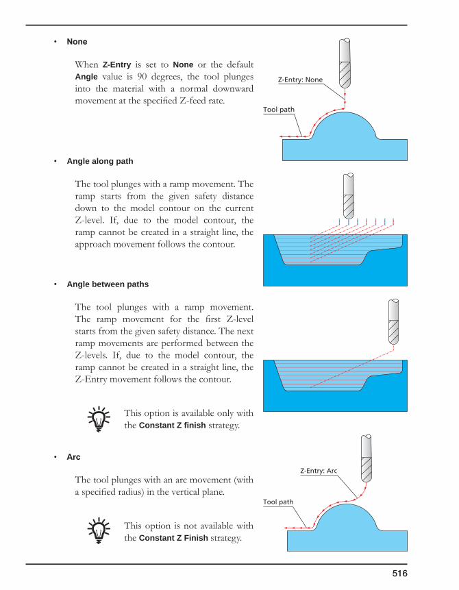
516
• None
When Z-Entry is set to None or the default Angle value is 90 degrees, the tool plunges into the material with a normal downward movement at the specified Z-feed rate.
• Angle along path
The tool plunges with a ramp movement. The ramp starts from the given safety distance down to the model contour on the current Z-level. If, due to the model contour, the ramp cannot be created in a straight line, the approach movement follows the contour.
• Angle between paths
The tool plunges with a ramp movement. The ramp movement for the first Z-level starts from the given safety distance. The next ramp movements are performed between the Z-levels. If, due to the model contour, the ramp cannot be created in a straight line, the Z-Entry movement follows the contour.
This option is available only with the Constant Z finish strategy.
• Arc
The tool plunges with an arc movement (with a specified radius) in the vertical plane.
This option is not available with the Constant Z Finish strategy.
Z-Entry: None
Tool path
Z-Entry: Arc
Tool path

7. 3D Milling
517
Tool path arrangement
SolidCAM provides you with improved arrangement of the tool path generated by the projection strategies (Linear, Circular pocket, etc.) to minimize the number of jumps between the tool path segments.
Consider the tool path generated by the Linear strategy. SolidCAM generates the planar pattern and projects it on the model.
The resulting tool path is trimmed by the working area; as a result some of the tool path lines are divided into a number of segments.
At the next stage, SolidCAM connects the tool path lines into several continuous chains (in this example – three chains), in such a way as to minimize the jumps between them.
1
2
3
1 2 3 4 5 6 7 8 9 10 11 12 13 14
1 2 3 4 5 6 7 8 9 10 11 12 13 14
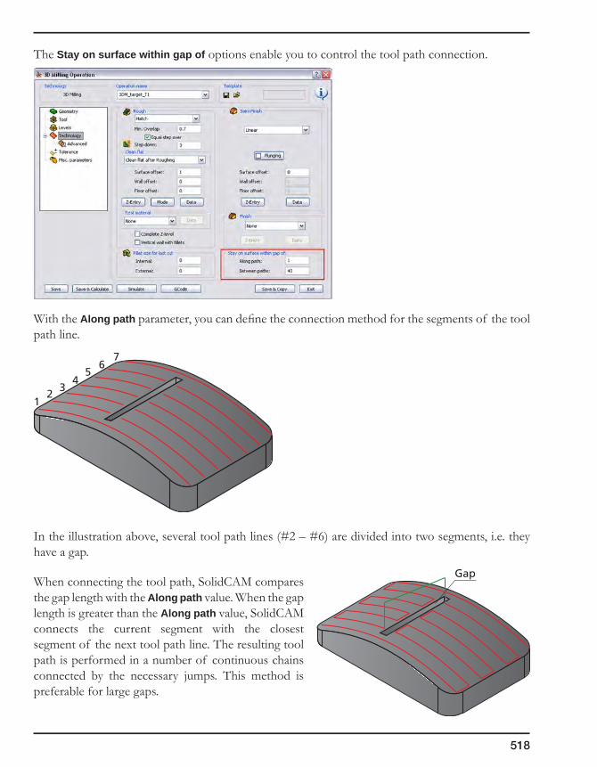
518
The Stay on surface within gap of options enable you to control the tool path connection.
With the Along path parameter, you can define the connection method for the segments of the tool path line.
In the illustration above, several tool path lines (#2 – #6) are divided into two segments, i.e. they have a gap.
When connecting the tool path, SolidCAM compares the gap length with the Along path value. When the gap length is greater than the Along path value, SolidCAM connects the current segment with the closest segment of the next tool path line. The resulting tool path is performed in a number of continuous chains connected by the necessary jumps. This method is preferable for large gaps.
12
34
56
7
Gap

7. 3D Milling
519
When the gap length is smaller than the Along path value, the segments of the tool path line are connected with the cutting movements directly on the surface. The resulting tool path is continuous and free of jumps. This method is preferable for small gaps.
The Between paths value determines the way the tool path lines and separate tool path chains are linked. When the distance between tool path chains is smaller than the specified value, the tool paths are connected with the cutting movements directly on the surface.
When the distance between tool path is greater than the specified Between paths value, the tool paths are connected with rapid movements via the Operation Clearance level.
When the distance between tool path lines is greater than the Between paths value, the tool path lines are also connected with rapid movements.
Link movement
Gap
Link movement
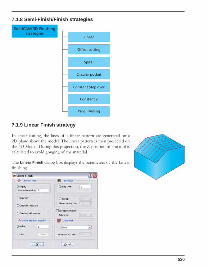
520
7.1.8 Semi-Finish/Finish strategies
7.1.9 Linear Finish strategy
In linear cutting, the lines of a linear pattern are generated on a 2D plane above the model. The linear pattern is then projected on the 3D Model. During this projection, the Z-position of the tool is calculated to avoid gouging of the material.
The Linear Finish dialog box displays the parameters of the Linear finishing.
SolidCAM 3D Finishingstrategies
Linear
Offset cutting
Spiral
Circular pocket
Constant Z
Pencil Milling
Constant Step over
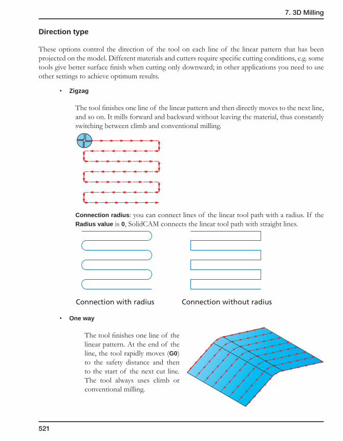
7. 3D Milling
521
Direction type
These options control the direction of the tool on each line of the linear pattern that has been projected on the model. Different materials and cutters require specific cutting conditions, e.g. some tools give better surface finish when cutting only downward; in other applications you need to use other settings to achieve optimum results.
• Zigzag
The tool finishes one line of the linear pattern and then directly moves to the next line, and so on. It mills forward and backward without leaving the material, thus constantly switching between climb and conventional milling.
Connection radius: you can connect lines of the linear tool path with a radius. If the Radius value is 0, SolidCAM connects the linear tool path with straight lines.
• One way
The tool finishes one line of the linear pattern. At the end of the line, the tool rapidly moves (G0) to the safety distance and then to the start of the next cut line. The tool always uses climb or conventional milling.
Connection with radius Connection without radius

522
• Oneway-Upward
The tool always cuts from the lowest point of the tool path line to the highest point. From the highest point of the cut, the tool moves rapidly to the start point of the next cut.
• Oneway-Downward
The tool always cuts from the highest point of the tool path line to the lowest point. From the lowest point of the cut, the tool moves rapidly to the start point of the next cut.
Define direction angle by
• Value
Enter the angle value that defines the orientation of the tool path. The value of 0 generates the tool path lines in the direction of the positive X-axis.
• Line
The Define button is available and you can define a line that determines the orientation of the tool path. The direction vector is defined by picking two points that define the start point and the end point of the direction line. The angle of the selected line is the output to the angle field.
Technology
• Step over
In linear finishing, SolidCAM generates a line pattern on a 2D plane above the model and then projects it on the 3D model. The Step over value determines the constant distance between all lines of the linear pattern created on the 2D plane before it is projected.

7. 3D Milling
523
• Scallop
This option enables you to control the distance between the tool path lines by the cusp height you want to achieve on the finished model. SolidCAM adjusts the distance between the single lines of the 2D pattern (before projection on the model) to the topology of the model to match the specified scallop height.
Maximum step over
On flat areas, bull nose tool can achieve a small scallop with a rather large step over. You can use this value if you want to limit the chip load on the tool or the cutting forces that a large step over could cause.
• Arc approximation
You can create G2/G3 GCode output from Linear finish operations. SolidCAM checks whether successive points of the calculated tool path can be connected using an arc or circle. If an arc or circle connection within the specified arc approximation tolerance can be made, you will receive arc and G2 and G3 circle interpolation commands in the generated GCode. This feature can drastically reduce the number of lines in GCode files. Most CNC-controllers and machines work much faster on arcs and circles than on single tool path points or splines. Arc approximation will increase actual feed rates on older CNC-machines and the machine will work smoother.
The Tolerance value defines the tolerance SolidCAM uses to position tool path points on arcs or circles
Cross finish
• None
Linear machining is performed only in the direction you have specified and no cross finish is executed.
• Normal
After finishing the model in the first specified direction, another linear finish is performed at an angle of 90° to the first cutting direction. The complete area that has been machined in the first cut linear operation is machined again.
Linear finish tool path
Normal cross finishtool path
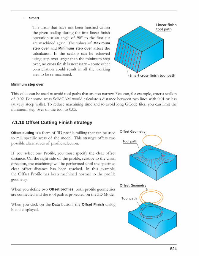
524
• Smart
The areas that have not been finished within the given scallop during the first linear finish operation at an angle of 90° to the first cut are machined again. The values of Maximum step over and Minimum step over affect the calculation. If the scallop can be achieved using step over larger than the minimum step over, no cross finish is necessary – some other constellation could result in all the working area to be re-machined.
Minimum step over
This value can be used to avoid tool paths that are too narrow. You can, for example, enter a scallop of 0.02. For some areas SolidCAM would calculate a distance between two lines with 0.01 or less (at very steep walls). To reduce machining time and to avoid long GCode files, you can limit the minimum step over of the tool to 0.05.
7.1.10 Offset Cutting Finish strategy
Offset cutting is a form of 3D profile milling that can be used to mill specific areas of the model. This strategy offers two possible alternatives of profile selection:
If you select one Profile, you must specify the clear offset distance. On the right side of the profile, relative to the chain direction, the machining will be performed until the specified clear offset distance has been reached. In this example, the Offset Profile has been machined normal to the profile geometry.
When you define two Offset profiles, both profile geometries are connected and the tool path is projected on the 3D Model.
When you click on the Data button, the Offset Finish dialog box is displayed.
Offset Geometry
Tool path
Offset Geometry
Tool path
Linear finishtool path
Smart cross-finish tool path
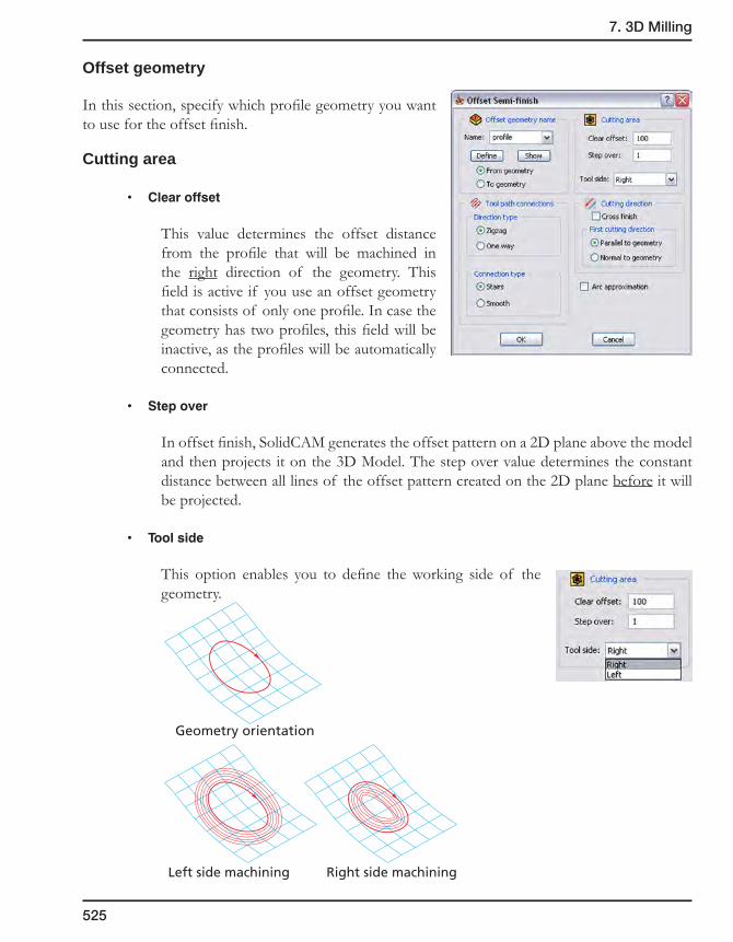
7. 3D Milling
525
Offset geometry
In this section, specify which profile geometry you want to use for the offset finish.
Cutting area
• Clearoffset
This value determines the offset distance from the profile that will be machined in the right direction of the geometry. This field is active if you use an offset geometry that consists of only one profile. In case the geometry has two profiles, this field will be inactive, as the profiles will be automatically connected.
• Stepover
In offset finish, SolidCAM generates the offset pattern on a 2D plane above the model and then projects it on the 3D Model. The step over value determines the constant distance between all lines of the offset pattern created on the 2D plane before it will be projected.
• Toolside
This option enables you to define the working side of the geometry.
Geometry orientation
Left side machining Right side machining
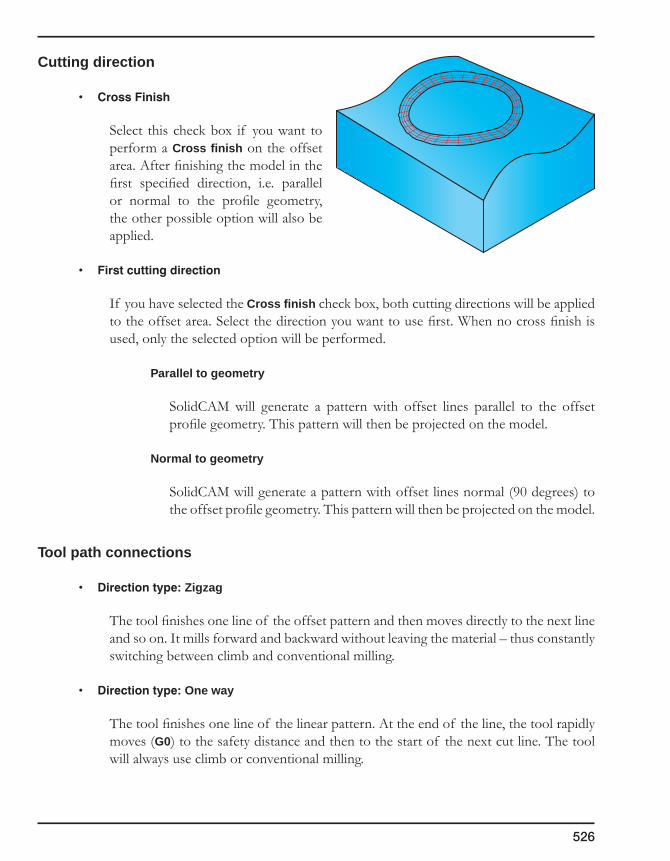
526
Cutting direction
• CrossFinish
Select this check box if you want to perform a Cross finish on the offset area. After finishing the model in the first specified direction, i.e. parallel or normal to the profile geometry, the other possible option will also be applied.
• Firstcuttingdirection
If you have selected the Cross finish check box, both cutting directions will be applied to the offset area. Select the direction you want to use first. When no cross finish is used, only the selected option will be performed.
Parallel to geometry
SolidCAM will generate a pattern with offset lines parallel to the offset profile geometry. This pattern will then be projected on the model.
Normal to geometry
SolidCAM will generate a pattern with offset lines normal (90 degrees) to the offset profile geometry. This pattern will then be projected on the model.
Tool path connections
• Directiontype:Zigzag
The tool finishes one line of the offset pattern and then moves directly to the next line and so on. It mills forward and backward without leaving the material – thus constantly switching between climb and conventional milling.
• Directiontype:One way
The tool finishes one line of the linear pattern. At the end of the line, the tool rapidly moves (G0) to the safety distance and then to the start of the next cut line. The tool will always use climb or conventional milling.
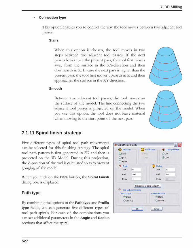
7. 3D Milling
527
• Connection type
This option enables you to control the way the tool moves between two adjacent tool passes.
Stairs
When this option is chosen, the tool moves in two steps between two adjacent tool passes. If the next pass is lower than the present pass, the tool first moves away from the surface in the XY-direction and then downwards in Z. In case the next pass is higher than the present pass, the tool first moves upwards in Z and then approaches the surface in the XY-direction.
Smooth
Between two adjacent tool passes, the tool moves on the surface of the model. The line connecting the two adjacent tool passes is projected on the model. When you use this option, the tool does not leave material when moving to the start point of the next pass.
7.1.11 Spiral finish strategy
Five different types of spiral tool path movements can be selected for this finishing strategy. The spiral tool path pattern is first generated in 2D and then is projected on the 3D Model. During this projection, the Z-position of the tool is calculated so as to prevent gouging of the model.
When you click on the Data button, the Spiral Finish dialog box is displayed.
Path type
By combining the options in the Path type and Profile type fields, you can generate five different types of tool path spirals. For each of the combinations you can set additional parameters in the Angle and Radius sections that affect the spiral.
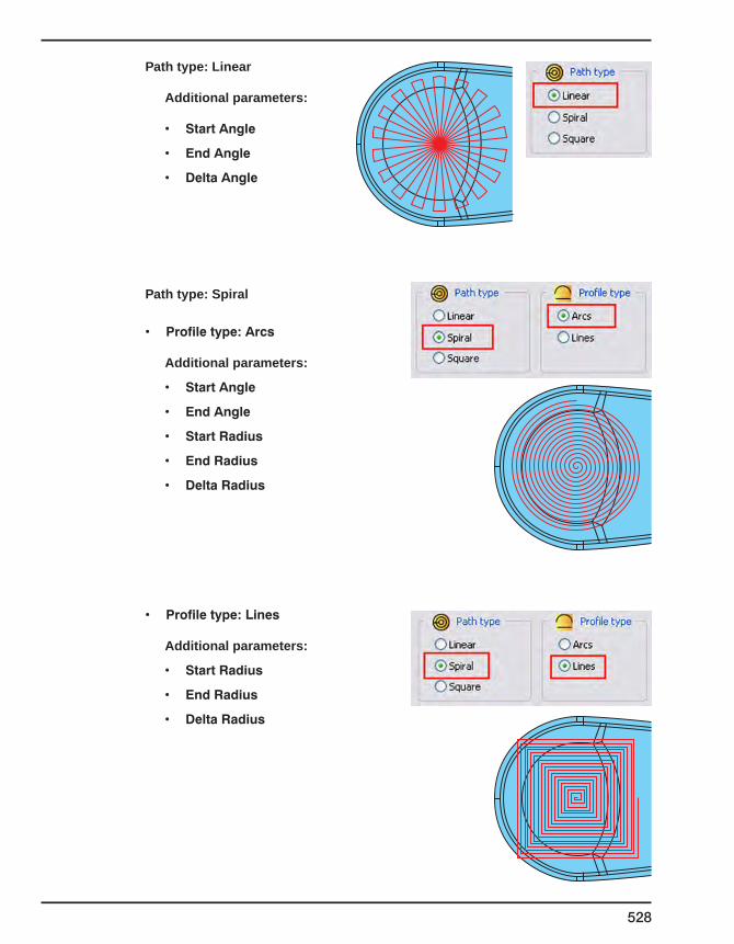
528
Path type: Linear
Additional parameters:
• StartAngle
• EndAngle
• DeltaAngle
Path type: Spiral
• Profiletype:Arcs
Additional parameters:
• StartAngle
• EndAngle
• StartRadius
• EndRadius
• DeltaRadius
• Profiletype:Lines
Additional parameters:
• StartRadius
• EndRadius
• DeltaRadius
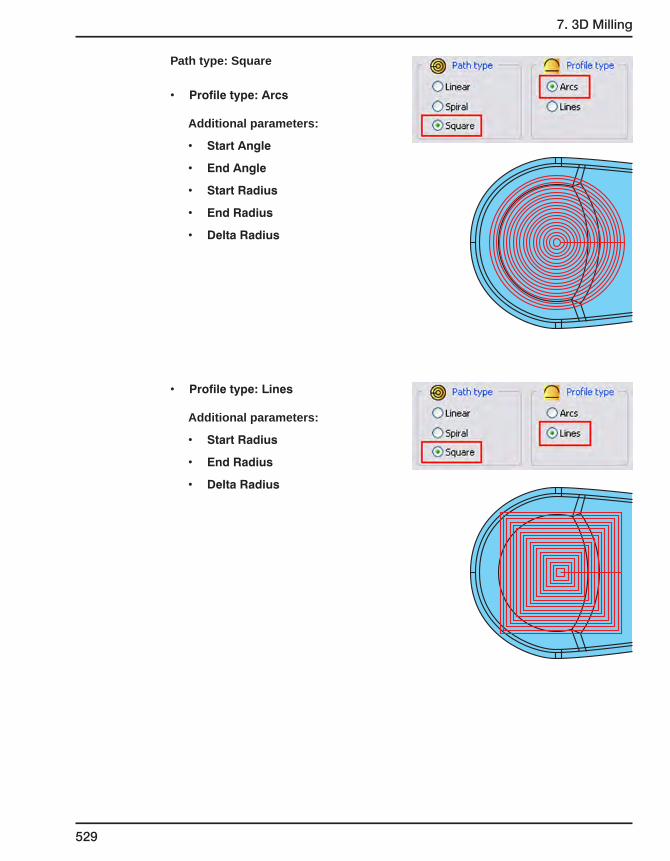
7. 3D Milling
529
Path type: Square
• Profiletype:Arcs
Additional parameters:
• StartAngle
• EndAngle
• StartRadius
• EndRadius
• DeltaRadius
• Profiletype:Lines
Additional parameters:
• StartRadius
• EndRadius
• DeltaRadius

530
Cutting direction
The spiral is machined in the clockwise (CW) or counterclockwise (CCW) direction. The direction also affects the machined angle area. Machining always starts at the angle given in Start angle up to the End angle in the cutting direction.
Angle
You can limit the angle area that will be machined by setting values for the Start and End angle. The direction of the positive X-axis is entered with a value of 0 degrees. Machining will always start from the given start angle and will move in the cutting direction towards the end angle.
The Delta angle is used to specify the angle steps of the tool path spiral in the Path type: Linear option.
Radius
You can set values for the Start and End radius of the tool path spiral.
The Delta radius specifies the offset distance to the next circle or spiral circumference of the tool path spiral.
Pick center of tool path spiral
This button enables you to define the center of the tool path spiral that will be projected on the model. If you do not choose any center, the system uses the current Coordinate system origin as the center of the spiral.
Enter the X,Y,Z coordinates of the center point into the Pick center point of tool path spiral dialog box or define a point by picking and confirm by clicking on the button.
Tool path connections
• Direction type: Zigzag
The tool finishes one line of the spiral pattern and then moves directly to the next tool path line and so on. It mills forward and backward without leaving the material, thus constantly switching between climb milling and conventional milling.
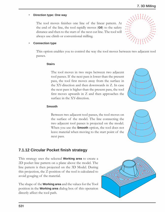
7. 3D Milling
531
• Direction type: One way
The tool moves finishes one line of the linear pattern. At the end of the line, the tool rapidly moves (G0) to the safety distance and then to the start of the next cut line. The tool will always use climb or conventional milling.
• Connection type
This option enables you to control the way the tool moves between two adjacent tool passes.
Stairs
The tool moves in two steps between two adjacent tool passes. If the next pass is lower than the present pass, the tool first moves away from the surface in the XY-direction and then downwards in Z. In case the next pass is higher than the present pass, the tool first moves upwards in Z and then approaches the surface in the XY-direction.
Smooth
Between two adjacent tool passes, the tool moves on the surface of the model. The line connecting the two adjacent tool passes is projected on the model. When you use the Smooth option, the tool does not leave material when moving to the start point of the next pass.
7.1.12 Circular Pocket finish strategy
This strategy uses the selected Working area to create a 2D pocket line pattern on a plane above the model. The line pattern is then projected on the 3D Model. During this projection, the Z-position of the tool is calculated to avoid gouging of the material.
The shape of the Working area and the values for the Tool position in the Working area dialog box of this operation directly affect the tool path.

532
The Circular Pocket Finish dialog box displays the parameters of the Circular Pocket Finish strategy.
Cutting direction
The pocket can be machined in Conventional or Climb direction.
Start from
The machining can be started from Outside or Inside the pocket.
The combination of both fields, Cutting direction and Start from, will result in climb or conventional milling. Select CCW/Outside or CW/Inside to perform climb milling; any other combination will result in conventional milling of the model.
Connection type
This option enables you to control the way the tool moves between two adjacent tool passes.
• Stairs
The tool moves in two steps between two adjacent tool passes. If the next pass is lower than the present pass, the tool first moves away from the surface in the XY-direction and then downwards in Z. In case the next pass is higher than the present pass, the tool first moves upwards in Z and then approaches the surface in the XY-direction.
• Smooth
Between two adjacent tool passes, the tool moves on the surface of the model. The line connecting the two adjacent tool passes is projected on the model. When you use the Smooth option, the tool does not leave material when moving to the start point of the next pass.
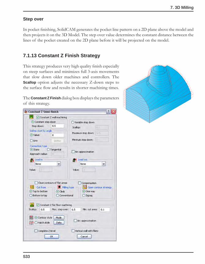
7. 3D Milling
533
Step over
In pocket finishing, SolidCAM generates the pocket line pattern on a 2D plane above the model and then projects it on the 3D Model. The step over value determines the constant distance between the lines of the pocket created on the 2D plane before it will be projected on the model.
7.1.13 Constant Z Finish Strategy
This strategy produces very high quality finish especially on steep surfaces and minimizes full 3-axis movements that slow down older machines and controllers. The Scallop option adjusts the necessary Z-down steps to the surface flow and results in shorter machining times.
The Constant Z Finish dialog box displays the parameters of this strategy.
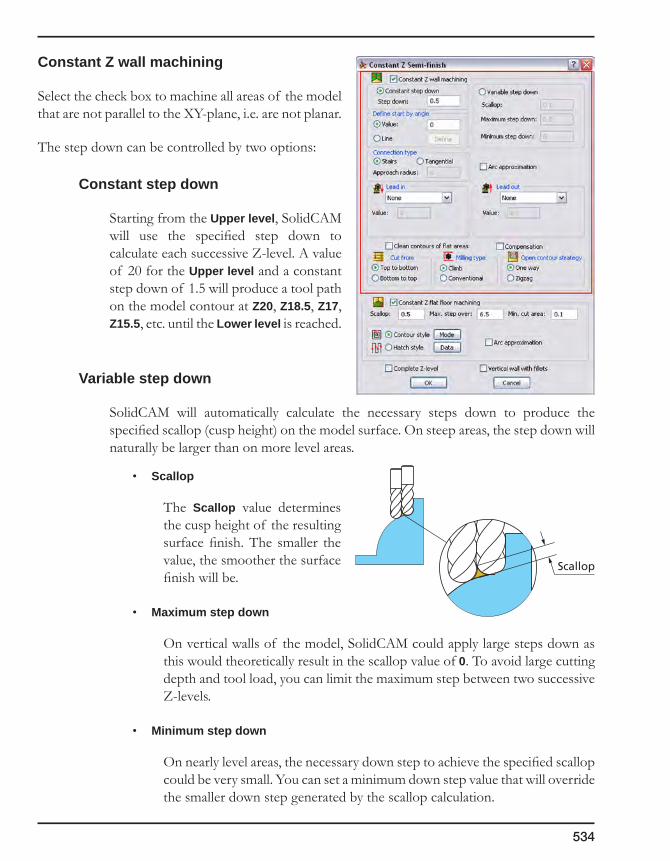
534
Constant Z wall machining
Select the check box to machine all areas of the model that are not parallel to the XY-plane, i.e. are not planar.
The step down can be controlled by two options:
Constant step down
Starting from the Upper level, SolidCAM will use the specified step down to calculate each successive Z-level. A value of 20 for the Upper level and a constant step down of 1.5 will produce a tool path on the model contour at Z20, Z18.5, Z17, Z15.5, etc. until the Lower level is reached.
Variable step down
SolidCAM will automatically calculate the necessary steps down to produce the specified scallop (cusp height) on the model surface. On steep areas, the step down will naturally be larger than on more level areas.
• Scallop
The Scallop value determines the cusp height of the resulting surface finish. The smaller the value, the smoother the surface finish will be.
• Maximum step down
On vertical walls of the model, SolidCAM could apply large steps down as this would theoretically result in the scallop value of 0. To avoid large cutting depth and tool load, you can limit the maximum step between two successive Z-levels.
• Minimum step down
On nearly level areas, the necessary down step to achieve the specified scallop could be very small. You can set a minimum down step value that will override the smaller down step generated by the scallop calculation.
Scallop
7. 3D Milling
535
Start machining (Define start by angle)
• Value
Enter the angle that defines the start position of the tool path. The value of 0 will generate the tool path start point on the intersection of the contour and the positive X-axis.
• Line
When you choose this option, the Define button is activated and you can define a line that determines the orientation of the tool path. The direction vector is defined by picking two points that define the start point and end point of the direction line. The angle of the selected line will be output to the angle field.
Arc approximation
This command enables you to create G2/G3 GCode output from Constant Z operations. SolidCAM checks whether successive points of the calculated tool path can be connected using an arc or circle. If an arc or circle connection within the specified arc approximation tolerance can be made, you will receive arc and G2 and G3 circle interpolation commands in the generated GCode.
This feature can drastically reduce the number of lines in GCode files. Most CNC-controllers and machines work much faster on arcs and circles than on single tool path points or splines. Arc approximation will increase actual feed rates on older CNC-machines and the machine will work smoother.
The Tolerance value defines the tolerance SolidCAM uses to position tool path points on arcs or circles.
The arc approximation value should be smaller than the specified value for the surface offset. A warning message will be displayed if a larger value could cause gouging of the model.
Lead in/Lead out
You can control the way the tool leads in and leads out from the profile. Select an option from the list and enter the distance value for this option.

536
The following Lead in/Lead out strategies are available:
• None
• Normal
• Arc
• Tangent
• Point
For more information on the Lead in/Lead out options, see topic 6.1.3.
Compensation
This option enables SolidCAM to use the tool radius compensation options G4x of the CNC-controller in the GCode output.
Clean contours of flat areas
In prismatic solid parts, if there is a ledge at a depth that falls between down steps or a wall at the edge of a flat bottom of Constant Z machining, SolidCAM can still recognize this ledge or wall and machine it as if in a Profile operation (between the machining of the previous and next Z-steps).
Connection type
This option enables you to control the way the tool moves between two adjacent tool passes.
• Stairs
The tool moves in two steps between two adjacent tool passes. If the next pass is lower than the present pass, the tool first moves away from the surface in the XY-direction and then downwards in Z. In case the next pass is higher than the present pass, the tool first moves upwards in Z and then approaches the surface in the XY-direction.
• Tangential
Between two adjacent tool passes, the tool moves away from the contour in a tangent movement. It continues in a 3D arc/spiral movement to the next Z-level and then approaches the contour in another tangent movement.
7. 3D Milling
537
The Tangential tool path connection smooths lead in/out moves and is especially useful for High Speed Machining. You can avoid “witness marks” on the model that can be caused from a Z approach movement on the model surface.
The Approach radius parameter defines the radius of the 3D arc that is used to create the tangential move between two successive Z-levels. The value is the maximum radius used as SolidCAM will automatically reduce the radius if the model topology will not leave enough space to approach with the specified radius. This could happen in narrow cavities of the model when a large tool is being used.
Cutting direction (Cut from)
• Toptobottom
The machining starts on the Upper level and continue downward in the -Z direction until the Lower level is reached. The tool finishes one line of the linear pattern, moves directly to the next line and so on. It mills forward and backward without leaving the material, thus constantly changing between climb milling and conventional milling.
• Bottomtotop
The machining starts from the Lower level and continue towards the Upper level.
Milling type
• Climb
The tool cuts on the left side of the model contour. Unless the selected Open contour strategy is set to Zigzag, contours are always machined in the climb milling direction.
• Conventional
The tool will cut on the right side of the model contour. On outside contours, this will generate a tool path in clockwise direction.
Open contour strategy
This field controls the milling direction on contours that cannot be closed because the model or a specified working area does not enable SolidCAM to continue the tool path in a closed loop.
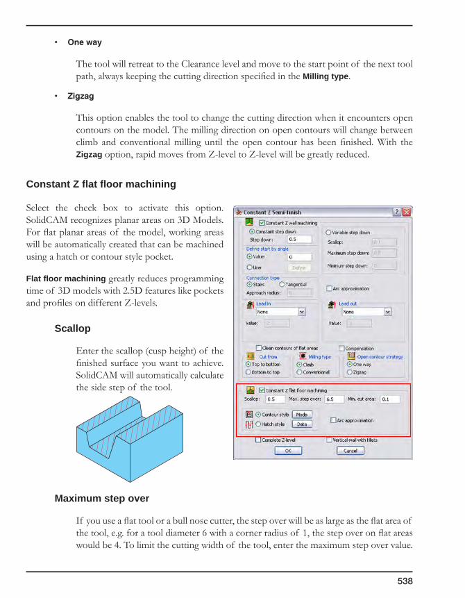
538
• Oneway
The tool will retreat to the Clearance level and move to the start point of the next tool path, always keeping the cutting direction specified in the Milling type.
• Zigzag
This option enables the tool to change the cutting direction when it encounters open contours on the model. The milling direction on open contours will change between climb and conventional milling until the open contour has been finished. With the Zigzag option, rapid moves from Z-level to Z-level will be greatly reduced.
Constant Z flat floor machining
Select the check box to activate this option. SolidCAM recognizes planar areas on 3D Models. For flat planar areas of the model, working areas will be automatically created that can be machined using a hatch or contour style pocket.
Flat floor machining greatly reduces programming time of 3D models with 2.5D features like pockets and profiles on different Z-levels.
Scallop
Enter the scallop (cusp height) of the finished surface you want to achieve. SolidCAM will automatically calculate the side step of the tool.
Maximum step over
If you use a flat tool or a bull nose cutter, the step over will be as large as the flat area of the tool, e.g. for a tool diameter 6 with a corner radius of 1, the step over on flat areas would be 4. To limit the cutting width of the tool, enter the maximum step over value.

7. 3D Milling
539
Minimum cut area
This parameter defines the size of the minimum area that will be machined.
Machining style
SolidCAM enables you to choose two styles of the floor machining during Constant Z finishing:
• Contour style
Select this option if you want to machine the flat floor areas on your model as a contour style pocket. The pocket tool path will travel at parallel offsets to the outside contour of the flat area.
1. Choose the Contour strategy.
2. Click on the Data button to define the Contour parameters.
For more information on the Contour machining, see topic 6.4.3.
• Hatch style
The tool mills the flat area in a linear pattern.
1. Choose the Hatch strategy.
2. Click on the Data button to define the Hatch parameters.
For more information on the Hatch machining, see topic 6.4.3.
With the Mode button, SolidCAM locates open pocket areas and enables you to machine them with a specific strategy. This strategy enables you to combine pocket and profile tool paths in order to provide the best productivity in open pocket machining.
For more information on the Open Pocket machining, see topic 6.4.3.
Arc approximation
This command enables you to create G2/G3 GCode output from Constant Z operations. SolidCAM checks whether successive points of the calculated tool path can be connected using an arc or circle. If an arc or circle connection within the specified arc approximation tolerance can be made, you will receive arc and G2 and G3 circle interpolation commands in the generated GCode.

540
This feature can drastically reduce the number of lines in GCode files. Most CNC-controllers and machines work much faster on arcs and circles than on single tool path points or splines. Arc approximation will increase actual feed rates on older CNC-machines and the machine will work smoother.
Complete Z-Level
This option enables you to define the order of the machining Z-levels.
For more information on this subject, see topic 7.1.3.
Vertical wall with fillets
This option enables special handling of vertical walls with fillets between them in a prismatic part.
For more information on this subject, see topic 7.1.3.
7.1.14 Constant Step over strategy
The 3D Projection Machining strategies generate a 2D tool path mesh, with a constant Step over in the plane parallel to the XY-plane of the current Coordinate System. This 2D tool path mesh is then projected on the 3D Model to get the 3D tool path. This method provides good results for prismatic parts machining but has a significant disadvantage for machining of curved surfaces because it does not take into account the surface curvature.
Tool path with the constant Step over in the XY-plane
Tool path with the constant Step over along the surface generated by the Constant
Step over strategy

7. 3D Milling
541
Constant Step over gives an excellent surface finish because the step over is constant along all surfaces irrespective of whether they are steep walls or shallow areas.
SolidCAM provides four types of the Constant Step over strategy:
• Profile with offset
• Profilewithlimit
• Ruledsurface
• Pocket-autoboundaries
The appropriate geometry has to be defined for all of these options.
Profile with offset
The tool mills from the geometry you have chosen to the Clear offset distance. Specify the Step over distance.
Note that both Step over and Clear offset are measured along the surface.
The Tool side option defines the position of the tool relative to the geometry or, in other words, the side of the geometry where the tool path will be applied.
Geometry
Step over
Clear offset
Tool path

542
The tool mills within the geometry until it has machined the entire pocket. The geometry used with this option must consist of several closed chains, similar to the geometry for a regular Pocket operation.
SolidCAM defines a number of offsets to the geometry with the specified Step over (measured along the surface). If there is an island, the tool will mill evenly from the outside chain toward the island and from the island toward the outside chain. The two paths will join in the middle between the two chains. The shape of the tool path is determined by both the outside geometry and the island geometry.
SolidCAM enables you to define the cutting direction:
• The Start from option enables you to start machining either from Outside or Inside the pocket.
• The Direction option enables you to choose Conventional or Climb milling.
Pocket geometry
Tool path
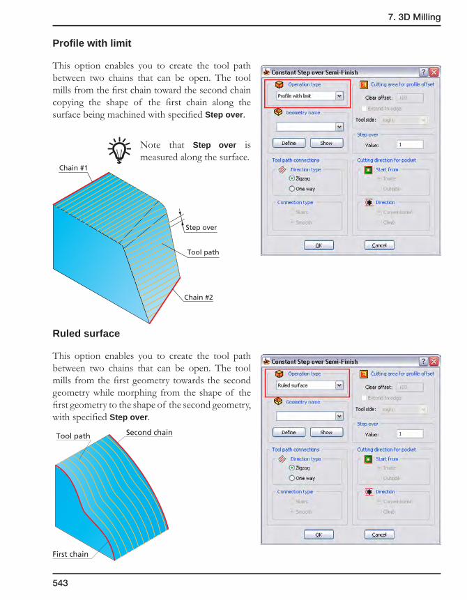
7. 3D Milling
543
Profile with limit
This option enables you to create the tool path between two chains that can be open. The tool mills from the first chain toward the second chain copying the shape of the first chain along the surface being machined with specified Step over.
Note that Step over is measured along the surface.
Ruled surface
This option enables you to create the tool path between two chains that can be open. The tool mills from the first geometry towards the second geometry while morphing from the shape of the first geometry to the shape of the second geometry, with specified Step over.
Tool path
Chain #1
Step over
Chain #2
First chain
Second chainTool path
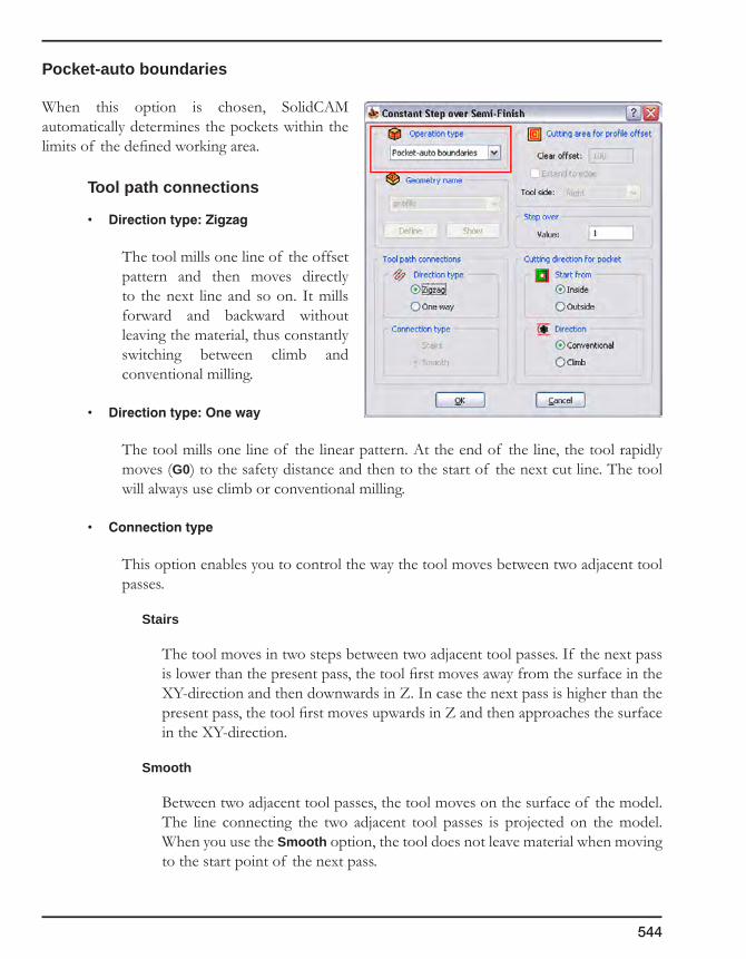
544
Pocket-auto boundaries
When this option is chosen, SolidCAM automatically determines the pockets within the limits of the defined working area.
Tool path connections
• Directiontype:Zigzag
The tool mills one line of the offset pattern and then moves directly to the next line and so on. It mills forward and backward without leaving the material, thus constantly switching between climb and conventional milling.
• Directiontype:Oneway
The tool mills one line of the linear pattern. At the end of the line, the tool rapidly moves (G0) to the safety distance and then to the start of the next cut line. The tool will always use climb or conventional milling.
• Connectiontype
This option enables you to control the way the tool moves between two adjacent tool passes.
Stairs
The tool moves in two steps between two adjacent tool passes. If the next pass is lower than the present pass, the tool first moves away from the surface in the XY-direction and then downwards in Z. In case the next pass is higher than the present pass, the tool first moves upwards in Z and then approaches the surface in the XY-direction.
Smooth
Between two adjacent tool passes, the tool moves on the surface of the model. The line connecting the two adjacent tool passes is projected on the model. When you use the Smooth option, the tool does not leave material when moving to the start point of the next pass.

7. 3D Milling
545
Extend to edge
When this check box is not selected, the tool path is generated from the position where the tool center is aligned with the end point of the face; this could leave an unmachined area. When this check box is selected, the tool path is extended till the tool is tangent to the face, at the start point of the face.
7.1.15 Pencil milling
To clean out corners for semi-finishing operations, the typical method in the past was to pick two surfaces that form a corner and drive a tool along their intersection. This method worked well enough for small or simple parts or for complicated parts if there was plenty of time for programming. But because of the time required to manually pick and cut all of the corners for different sized tools, this step has been foregone in many cases, creating a dangerous condition for high speed machining.
Pencil milling uses an algorithm that finds all of the corners of a part and automatically drives a tool along those corners.
The Extend to Edge optionis turned off
Unmachinedarea
The Extend to Edge optionis turned on
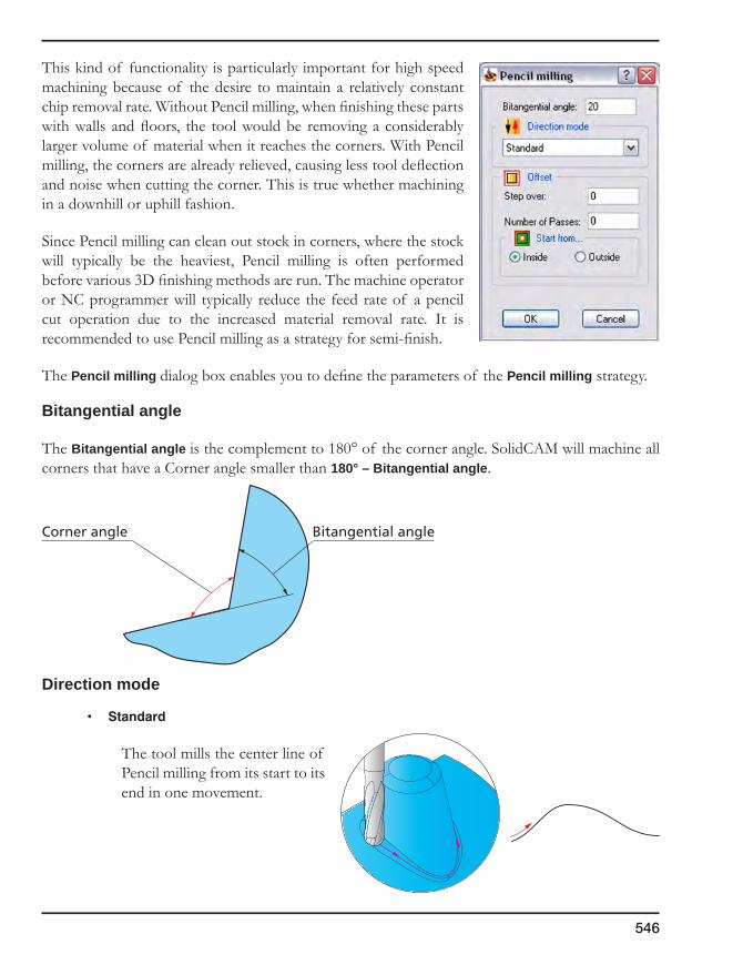
546
This kind of functionality is particularly important for high speed machining because of the desire to maintain a relatively constant chip removal rate. Without Pencil milling, when finishing these parts with walls and floors, the tool would be removing a considerably larger volume of material when it reaches the corners. With Pencil milling, the corners are already relieved, causing less tool deflection and noise when cutting the corner. This is true whether machining in a downhill or uphill fashion.
Since Pencil milling can clean out stock in corners, where the stock will typically be the heaviest, Pencil milling is often performed before various 3D finishing methods are run. The machine operator or NC programmer will typically reduce the feed rate of a pencil cut operation due to the increased material removal rate. It is recommended to use Pencil milling as a strategy for semi-finish.
The Pencil milling dialog box enables you to define the parameters of the Pencil milling strategy.
Bitangential angle
The Bitangential angle is the complement to 180° of the corner angle. SolidCAM will machine all corners that have a Corner angle smaller than 180° – Bitangential angle.
Direction mode
• Standard
The tool mills the center line of Pencil milling from its start to its end in one movement.
Bitangential angleCorner angle
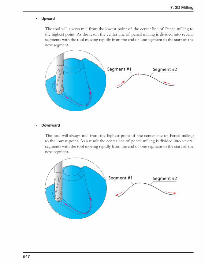
7. 3D Milling
547
• Upward
The tool will always mill from the lowest point of the center line of Pencil milling to the highest point. As the result the center line of pencil milling is divided into several segments with the tool moving rapidly from the end of one segment to the start of the next segment.
• Downward
The tool will always mill from the highest point of the center line of Pencil milling to the lowest point. As a result the center line of pencil milling is divided into several segments with the tool moving rapidly from the end of one segment to the start of the next segment.
Segment #1 Segment #2
Segment #1 Segment #2
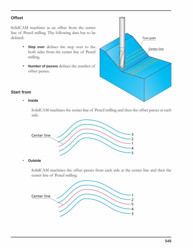
548
Offset
SolidCAM machines at an offset from the center line of Pencil milling. The following data has to be defined:
• Step over defines the step over to the both sides from the center line of Pencil milling.
• Number of passes defines the number of offset passes.
Start from
• Inside
SolidCAM machines the center line of Pencil milling and then the offset passes at each side.
• Outside
SolidCAM machines the offset passes from each side at the center line and then the center line of Pencil milling.
Center line
Tool path
123
45
Center line
521
43
Center line
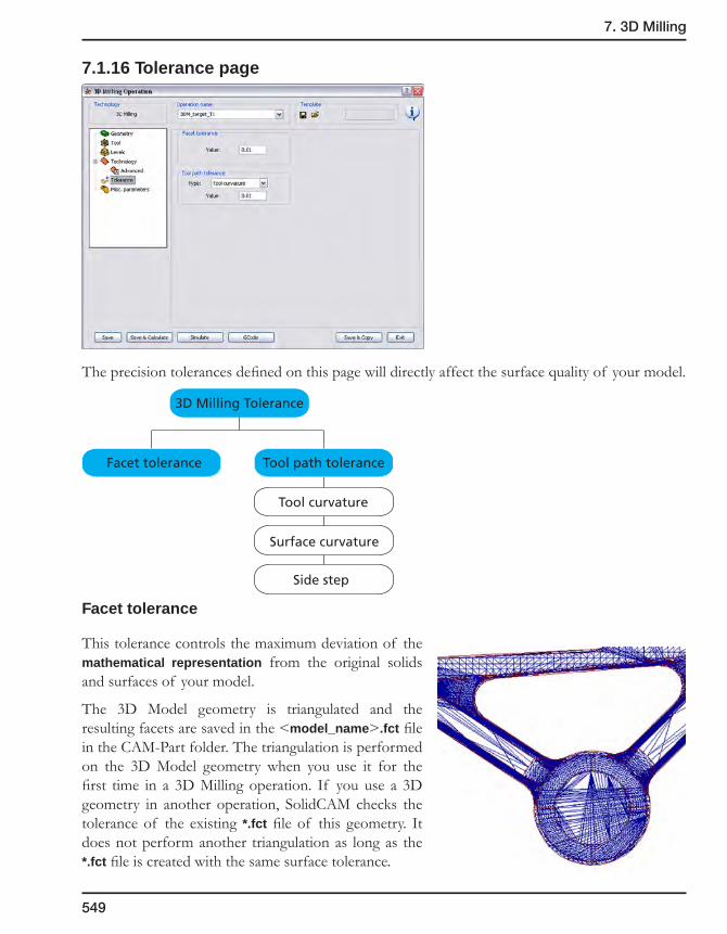
7. 3D Milling
549
7.1.16 Tolerance page
The precision tolerances defined on this page will directly affect the surface quality of your model.
Facet tolerance
This tolerance controls the maximum deviation of the mathematical representation from the original solids and surfaces of your model.
The 3D Model geometry is triangulated and the resulting facets are saved in the <model_name>.fct file in the CAM-Part folder. The triangulation is performed on the 3D Model geometry when you use it for the first time in a 3D Milling operation. If you use a 3D geometry in another operation, SolidCAM checks the tolerance of the existing *.fct file of this geometry. It does not perform another triangulation as long as the *.fct file is created with the same surface tolerance.
3D Milling Tolerance
Facet tolerance Tool path tolerance
Tool curvature
Surface curvature
Side step

550
Tool path tolerance
SolidCAM generates the tool path in two steps:
1. SolidCAM generates a mathematical representation of the surfaces and solids of the 3D Model geometry within the given surface tolerance. The information about this triangulation process is stored in an internal *.fct file that is similar to an *.stl file.
2. SolidCAM calculates the tool path using the parameters specified for the tool and the milling strategy to calculate the single steps of the tool on the mathematical model created in the first step. The result of this calculation, the *.pjPCode file, later serves as input to the generation of the actual GCode file. During this calculation, SolidCAM uses the Tool path tolerance that affects the number of single steps in the tool path (accuracy of the tool path).
The tool path tolerance can be defined by the following criteria:
Tool curvature
The accuracy of the tool path depends on the Tool diameter and the specified tolerance value.
Surface curvature
The accuracy of the tool path depends on the surface curvature and the specified tolerance value.
Side step
This tolerance enables you to control the size of a single step that will be constant during the whole tool path.
Small tolerance values result in more GCode steps in the GCode file, but the resulting surface is closer to the mathematical model.
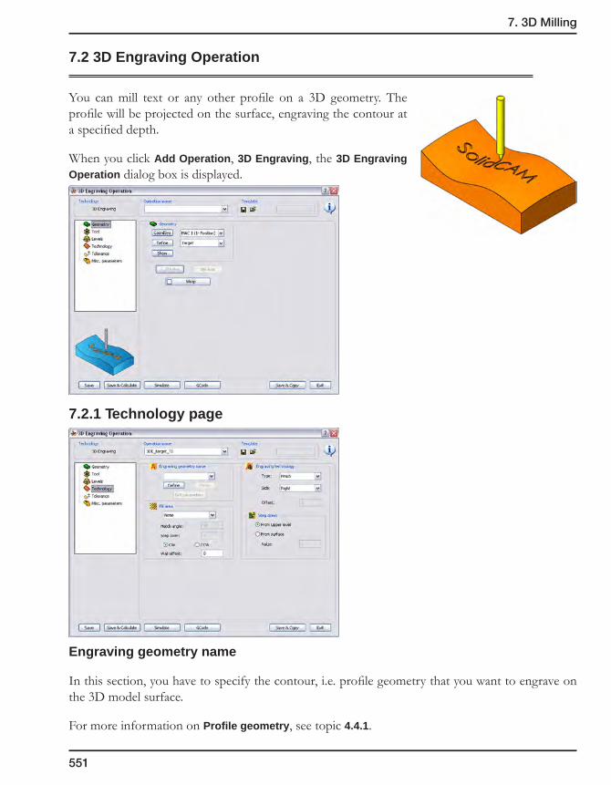
7. 3D Milling
551
7.2 3D Engraving Operation
You can mill text or any other profile on a 3D geometry. The profile will be projected on the surface, engraving the contour at a specified depth.
When you click Add Operation, 3D Engraving, the 3D Engraving Operation dialog box is displayed.
7.2.1 Technology page
Engraving geometry name
In this section, you have to specify the contour, i.e. profile geometry that you want to engrave on the 3D model surface.
For more information on Profile geometry, see topic 4.4.1.

552
Fill area
The area within the closed engraving geometry can be machined using the following strategies:
Hatch
SolidCAM fills the engraving geometry with a linear raster tool path, according to the specified Step over and Hatch angle.
Contour
The tool moves on offsets parallel to the pocket contour with the specified Step over.
The contours are machined in the clockwise (CW) or counterclockwise (CCW) direction.
The Wall offset parameter enables you to specify the offset from the engraving geometry. SolidCAM generates the contour equidistant to the engraving geometry at the specified offset. The engraving is performed inside this contour.
Engraving technology
Type
This option enables you to semi-finish and/or finish the engraved profile on the translated surface.
• The Semi-finish option enables you to prepare the engraving profile to an offset specified in the Offset field with cutting depths defined in the Step down section.
• The Finish option enables you to machine the engraving profile to its final dimensions in one step down.
• The Both option is used to machine the limit first with a semi-finishing cut and then with a finishing cut.
Hatchangle
Step over
Engravinggeometry
Step over
Engravinggeometry
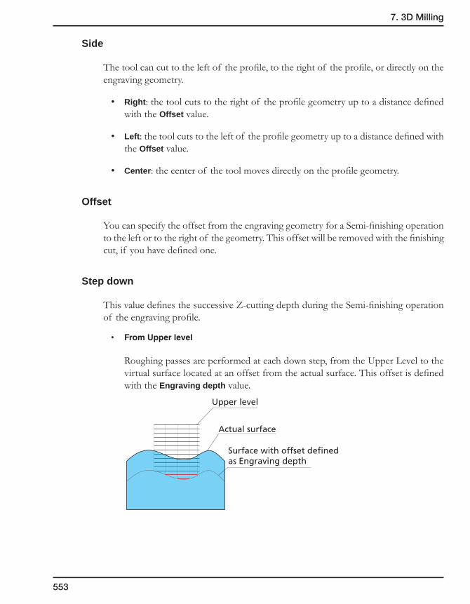
7. 3D Milling
553
Side
The tool can cut to the left of the profile, to the right of the profile, or directly on the engraving geometry.
• Right: the tool cuts to the right of the profile geometry up to a distance defined with the Offset value.
• Left: the tool cuts to the left of the profile geometry up to a distance defined with the Offset value.
• Center: the center of the tool moves directly on the profile geometry.
Offset
You can specify the offset from the engraving geometry for a Semi-finishing operation to the left or to the right of the geometry. This offset will be removed with the finishing cut, if you have defined one.
Step down
This value defines the successive Z-cutting depth during the Semi-finishing operation of the engraving profile.
• FromUpperlevel
Roughing passes are performed at each down step, from the Upper Level to the virtual surface located at an offset from the actual surface. This offset is defined with the Engraving depth value.
Upper level
Actual surface
Surface with offset defined as Engraving depth
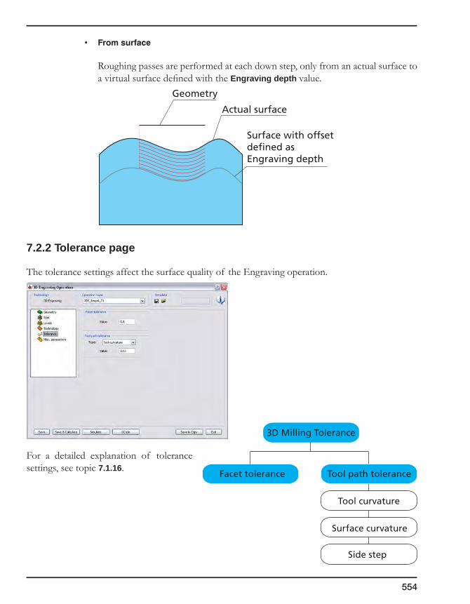
554
• Fromsurface
Roughing passes are performed at each down step, only from an actual surface to a virtual surface defined with the Engraving depth value.
7.2.2 Tolerance page
The tolerance settings affect the surface quality of the Engraving operation.
For a detailed explanation of tolerance settings, see topic 7.1.16.
Geometry
Actual surface
Surface with offsetdefined asEngraving depth
3D Milling Tolerance
Facet tolerance Tool path tolerance
Tool curvature
Surface curvature
Side step
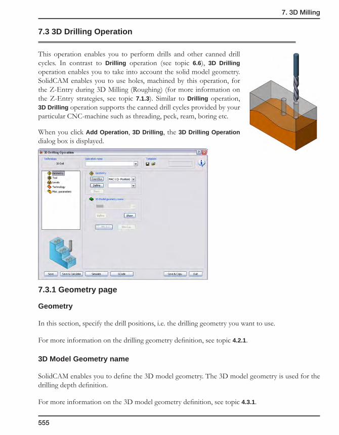
7. 3D Milling
555
7.3 3D Drilling Operation
This operation enables you to perform drills and other canned drill cycles. In contrast to Drilling operation (see topic 6.6), 3D Drilling operation enables you to take into account the solid model geometry. SolidCAM enables you to use holes, machined by this operation, for the Z-Entry during 3D Milling (Roughing) (for more information on the Z-Entry strategies, see topic 7.1.3). Similar to Drilling operation, 3D Drilling operation supports the canned drill cycles provided by your particular CNC-machine such as threading, peck, ream, boring etc.
When you click Add Operation, 3D Drilling, the 3D Drilling Operation dialog box is displayed.
7.3.1 Geometry page
Geometry
In this section, specify the drill positions, i.e. the drilling geometry you want to use.
For more information on the drilling geometry definition, see topic 4.2.1.
3D Model Geometry name
SolidCAM enables you to define the 3D model geometry. The 3D model geometry is used for the drilling depth definition.
For more information on the 3D model geometry definition, see topic 4.3.1.
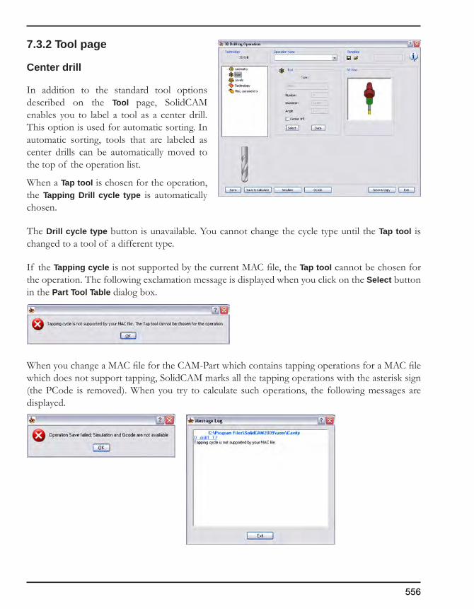
556
7.3.2 Tool page
Center drill
In addition to the standard tool options described on the Tool page, SolidCAM enables you to label a tool as a center drill. This option is used for automatic sorting. In automatic sorting, tools that are labeled as center drills can be automatically moved to the top of the operation list.
When a Tap tool is chosen for the operation, the Tapping Drill cycle type is automatically chosen.
The Drill cycle type button is unavailable. You cannot change the cycle type until the Tap tool is changed to a tool of a different type.
If the Tapping cycle is not supported by the current MAC file, the Tap tool cannot be chosen for the operation. The following exclamation message is displayed when you click on the Select button in the Part Tool Table dialog box.
When you change a MAC file for the CAM-Part which contains tapping operations for a MAC file which does not support tapping, SolidCAM marks all the tapping operations with the asterisk sign (the PCode is removed). When you try to calculate such operations, the following messages are displayed.

7. 3D Milling
557
7.3.3 Levels page
Offset from model
SolidCAM enables you to define the depth of the 3D drilling by the Offset from model value. This value can be either positive or negative. With the negative value SolidCAM enables the tool to go deeper into the solid model.
7.3.4 Technology page
Sequence of drill positions
This section enables you to define the sequence of the drill positions, manage its direction, etc.
For more information, see topic 6.6.3.
Solid model
Rest material
Offset frommodel
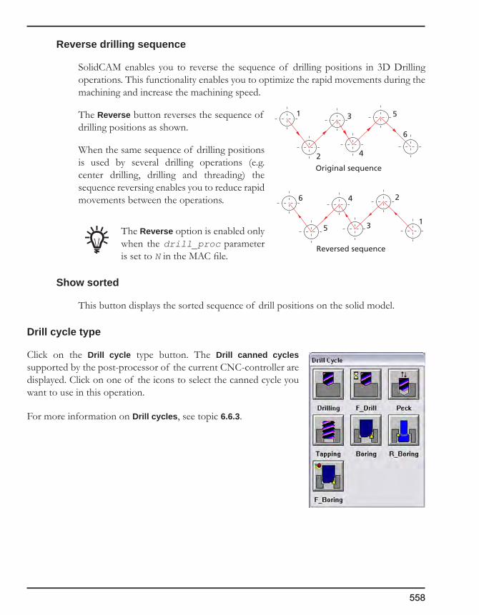
558
Reverse drilling sequence
SolidCAM enables you to reverse the sequence of drilling positions in 3D Drilling operations. This functionality enables you to optimize the rapid movements during the machining and increase the machining speed.
The Reverse button reverses the sequence of drilling positions as shown.
When the same sequence of drilling positions is used by several drilling operations (e.g. center drilling, drilling and threading) the sequence reversing enables you to reduce rapid movements between the operations.
The Reverse option is enabled only when the drill_proc parameter is set to N in the MAC file.
Show sorted
This button displays the sorted sequence of drill positions on the solid model.
Drill cycle type
Click on the Drill cycle type button. The Drill canned cycles supported by the post-processor of the current CNC-controller are displayed. Click on one of the icons to select the canned cycle you want to use in this operation.
For more information on Drill cycles, see topic 6.6.3.
1
2
3
4
5
6
Original sequence
Reversed sequence
1
2
3
4
5
6
MachiningProcesses 8
A Machining Process is comprised of a series of operations that are tied together through user-defined parameters. You can automate repetitive tasks in CNC-Programming with the Machining Process feature.
In subsequent identical or similar situations, Machining Processes can be used directly or adapted to a new situation by giving values to their parameters.
Machining Processes Table
Defining a new Machining Process
Operation Templates
Default Sets
Parameters & Expressions
Using Machining Processes
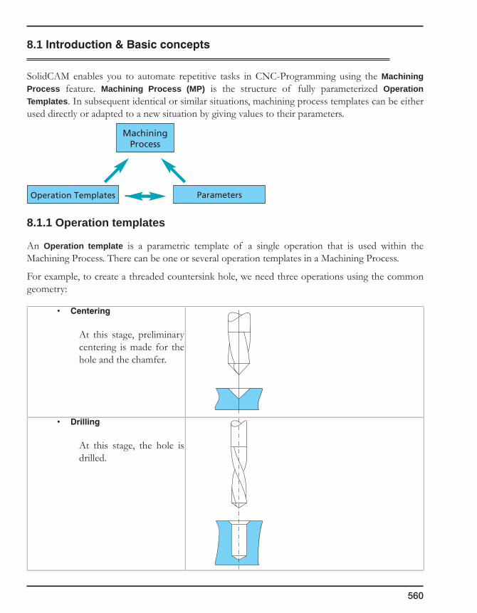
560
8.1Introduction&Basicconcepts
SolidCAM enables you to automate repetitive tasks in CNC-Programming using the Machining Process feature. Machining Process (MP) is the structure of fully parameterized Operation Templates. In subsequent identical or similar situations, machining process templates can be either used directly or adapted to a new situation by giving values to their parameters.
8.1.1 Operation templates
An Operation template is a parametric template of a single operation that is used within the Machining Process. There can be one or several operation templates in a Machining Process.
For example, to create a threaded countersink hole, we need three operations using the common geometry:
• Centering
At this stage, preliminary centering is made for the hole and the chamfer.
• Drilling
At this stage, the hole is drilled.
Operation Templates
MachiningProcess
Parameters

8. Machining Processes
561
• Threading
At this stage, the threading is performed.
8.1.2 Parameters&Expressions
Parameters can be given a constant value or an expression.
In the above example, the following parameters are required:
• The tap size (D_thread);
• The tap depth (H_thread);
• The drill depth (H_drill);
• The chamfer diameter (D_chamfer).
In the above example, you can define the following expression for centering depth:
With a group of such operation templates, parameters and expressions, you can define the universal Machining Process.
H_drill
D_chamfer
D_thread
H_thread
D_chamfer
α
H_center
H_center =D_chamfer/2
tan(α/2)
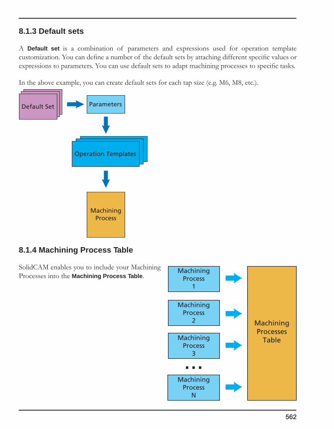
562
8.1.3 Default sets
A Default set is a combination of parameters and expressions used for operation template customization. You can define a number of the default sets by attaching different specific values or expressions to parameters. You can use default sets to adapt machining processes to specific tasks.
In the above example, you can create default sets for each tap size (e.g. M6, M8, etc.).
8.1.4 Machining Process Table
SolidCAM enables you to include your Machining Processes into the Machining Process Table.
Default Set
Operation Templates
Parameters
MachiningProcess
MachiningProcess
1
MachiningProcess
2
MachiningProcess
3
MachiningProcess
N
MachiningProcesses
Table

8. Machining Processes
563
8.2 Creating Machining Processes
Three basic stages are required to create a Machining Process.
SolidCAM enables you to use three major interface tools for these tasks:
• New Machining Process Table – in this dialog box, you can define a new MP Table. SolidCAM also enables you to manage existing MP Tables.
For more information on this subject, see topic 8.3.
• Machining Process Table Manager enables you to create and manage a single Machining Process in the Table.
For more information on this subject, see topic 8.4.
• Machining Process Define Manager enables you to define components of a single Machining Process: Operation Templates, Default sets, Parameters and Expressions.
For more information on this subject, see topic 8.6.
New Machining Process Table
Creating Machining Process Table
Creating Machining Process
Defining Machining Process components
Machining Process Table
Manager
Machining Process Define
Manager

564
8.3 Defining Machining Process Table
The first stage of the Machining Process creation is the definition of the Machining Process Table.
1. In SolidCAM Manager, right-click on the Machining Process header and choose the Milling type of the MP table from the New submenu.
The New Machining Process Table dialog box is displayed.
2. Enter a name for the Machining Process Table in the Table name field.
3. Click on the Add MAC file button to define the MAC file for your Machining Process Table. Since not all machines support all of the options in SolidCAM, you must also give the MAC file that you will be using. This will assure that only the options that are supported by your machine will be used.
4. Confirm the Machining Process Table creation with the OK button.
8.3.1 Adding MAC file(s)
The Add MAC file(s) dialog box enables you to choose a MAC file or a set of similar MAC files for your Machining Process. The MAC file contains options oriented to the specific CNC-machine. This file enables you to adapt your Machining Processes for your CNC-machines.
• AddingMACfile
1. Click on the Add button to choose the suitable MAC file from the list.

8. Machining Processes
565
2. In the dialog box displayed, pick the MAC file you wish to work with and click OK.
The Add MAC file(s) dialog box is displayed again with the chosen MAC file.
• AddingsimilarMACfiles
This option adds to the list any MAC file similar to the one you have originally picked. The criterion of the similarity is the coincidence of the MAC file options required for Machining Processes.
Please contact SolidCAM customer support for further details.
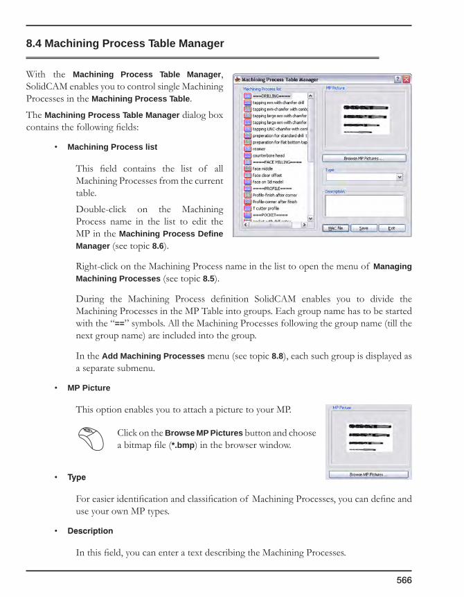
566
8.4 Machining Process Table Manager
With the Machining Process Table Manager, SolidCAM enables you to control single Machining Processes in the Machining Process Table.
The Machining Process Table Manager dialog box contains the following fields:
• Machining Process list
This field contains the list of all Machining Processes from the current table.
Double-click on the Machining Process name in the list to edit the MP in the Machining Process Define Manager (see topic 8.6).
Right-click on the Machining Process name in the list to open the menu of Managing Machining Processes (see topic 8.5).
During the Machining Process definition SolidCAM enables you to divide the Machining Processes in the MP Table into groups. Each group name has to be started with the “==” symbols. All the Machining Processes following the group name (till the next group name) are included into the group.
In the Add Machining Processes menu (see topic 8.8), each such group is displayed as a separate submenu.
• MP Picture
This option enables you to attach a picture to your MP.
Click on the Browse MP Pictures button and choose a bitmap file (*.bmp) in the browser window.
• Type
For easier identification and classification of Machining Processes, you can define and use your own MP types.
• Description
In this field, you can enter a text describing the Machining Processes.

8. Machining Processes
567
8.4.1 Managing Machining Process Tables
The Machining Process Tables menu contains the following options:
• Current
This option enables you to load the current MP Table in the Machining Process Table Manager (see topic 8.4).
• New
With this option, you can create a new MP Table. SolidCAM enables you to create four types of MP Tables: Milling, Turning, Turn-Mill, and Wire Cut.
• Open
This option enables you to load an MP Table via the standard Windows browser.
1. Right-click on the Machining Process header and choose Open from the submenu to load the Machining Process Table. The browser window is displayed.
2. Choose a Machining Process Table file (*.mpt).

568
The Machining Process Table is loaded and the Machining Process Table Manager is displayed.
• Copy
This option enables you to copy the MP Table.
The Copy Machining Process Table dialog box is displayed.
1. In the left field of the dialog box, choose an MP Table.
2. Click on the button to move the MP Table in the copy-container field.
You can use the button to remove MP Tables.
3. Choose the copy location in the right field.
4. Click on the Copy button to confirm the operation.
5. Click on the Exit button to close the dialog box.
• Delete
Choose this option to delete the MP Table via the standard Windows browser.
• RecentMPTables
This option displays a list of the last MP Tables you loaded in SolidCAM. You can open the file by clicking on the file you want to open.
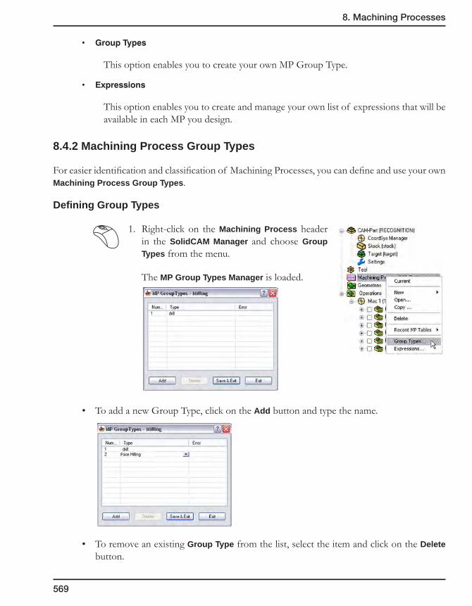
8. Machining Processes
569
• GroupTypes
This option enables you to create your own MP Group Type.
• Expressions
This option enables you to create and manage your own list of expressions that will be available in each MP you design.
8.4.2 Machining Process Group Types
For easier identification and classification of Machining Processes, you can define and use your own Machining Process Group Types.
Defining Group Types
1. Right-click on the Machining Process header in the SolidCAM Manager and choose Group Types from the menu.
The MP Group Types Manager is loaded.
• To add a new Group Type, click on the Add button and type the name.
• To remove an existing Group Type from the list, select the item and click on the Delete button.

570
• To edit the Group Type name, click on the icon in the name field and choose Edit - View.
The Edit dialog box is displayed. Change the MP Group Type name and confirm it with the OK button.
• You can use the F2 hotkey to open the Edit dialog box.
• By double-clicking on the Group Type name in the list, you can edit the name in the list directly without opening the Edit dialog box.
Using Group Types
The Machining Process Table Manager enables you to assign the Group Type to the Machining Process by choosing it from the list.
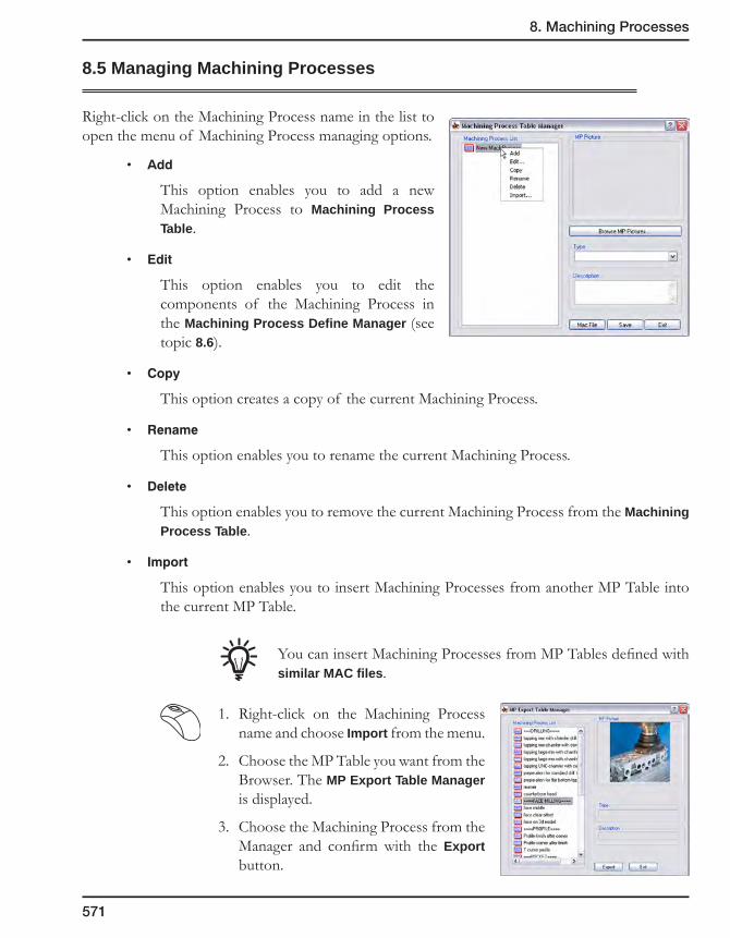
8. Machining Processes
571
8.5 Managing Machining Processes
Right-click on the Machining Process name in the list to open the menu of Machining Process managing options.
• Add
This option enables you to add a new Machining Process to Machining Process Table.
• Edit
This option enables you to edit the components of the Machining Process in the Machining Process Define Manager (see topic 8.6).
• Copy
This option creates a copy of the current Machining Process.
• Rename
This option enables you to rename the current Machining Process.
• Delete
This option enables you to remove the current Machining Process from the Machining Process Table.
• Import
This option enables you to insert Machining Processes from another MP Table into the current MP Table.
You can insert Machining Processes from MP Tables defined with similar MAC files.
1. Right-click on the Machining Process name and choose Import from the menu.
2. Choose the MP Table you want from the Browser. The MP Export Table Manager is displayed.
3. Choose the Machining Process from the Manager and confirm with the Export button.

572
8.6 Machining Process Define Manager
8.6.1 Operation Templates page
On this page, you can work with the set of Operation Templates in the same way as you work with conventional SolidCAM operations via SolidCAM Manager.
8.6.2 Define Operation Template
The Operation template dialog box contains the same fields you can find in the SolidCAM Operation dialog box.
You can now fill the fields of the Operation template in the same way as if you define a conventional
operation. Note that some fields in the Operation templates are marked with the button. These fields are parametric. In these fields, you can enter the following data:
• Variable
• Expression
• Value
If a variable you entered does not exist, SolidCAM adds it to the Used Parameters Table (see topic 8.6.6).
To edit this parametric field, you can use the parametric field menu by clicking on
the button.
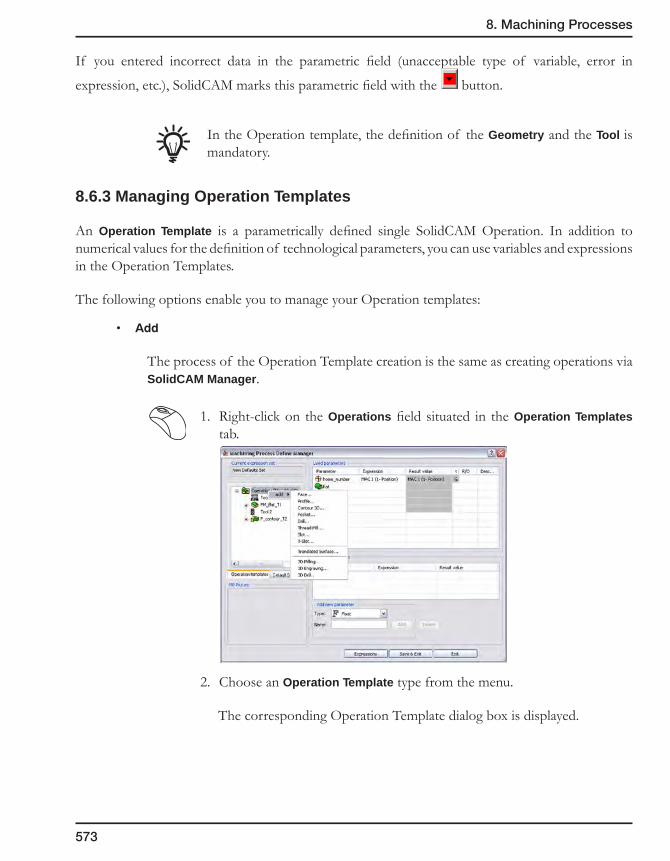
8. Machining Processes
573
If you entered incorrect data in the parametric field (unacceptable type of variable, error in
expression, etc.), SolidCAM marks this parametric field with the button.
In the Operation template, the definition of the Geometry and the Tool is mandatory.
8.6.3 Managing Operation Templates
An Operation Template is a parametrically defined single SolidCAM Operation. In addition to numerical values for the definition of technological parameters, you can use variables and expressions in the Operation Templates.
The following options enable you to manage your Operation templates:
• Add
The process of the Operation Template creation is the same as creating operations via SolidCAM Manager.
1. Right-click on the Operations field situated in the Operation Templates tab.
2. Choose an Operation Template type from the menu.
The corresponding Operation Template dialog box is displayed.

574
• Edit
This option enables you to edit the Operation Template.
The corresponding Operation Template dialog box is displayed.
• Delete
• ChangeTool
This option enables you to change the tool used in the specific Operation Template. The Part Tool Table dialog box (see topic 3.6) is displayed.
• Suppress/Unsuppress
SolidCAM enables you to suppress and unsuppress operation templates in the Machining Process.
The rules for suppressing and unsuppressing of the operation templates are the same as for operations. The suppressed/unsuppressed status of an operation template is the property of the operation template per default set, i.e. the same operation template can have a different status in different default sets. SolidCAM inserts suppressed operation templates from the Machining Process into the CAM-Part as suppressed operations.

8. Machining Processes
575
8.6.4 Parametric field menu
The parametric field menu enables you to choose parameters and expressions easily and effectively.
When you click on the button, the menu is displayed.
• User-definedparameters
This option displays a list of existing user-defined parameters.
Choose the variable name from the list.
You can open this list with the F5 hotkey when you are in the parametric field.
• Partparameters
This option displays a list of existing part parameters.
Choose the variable name from this list.
You can open this list with the F6 hotkey when you are in the parametric field.
• Expressions
This option displays the list of defined expressions.
You can open this list with the F7 hotkey when you are in the parametric field.
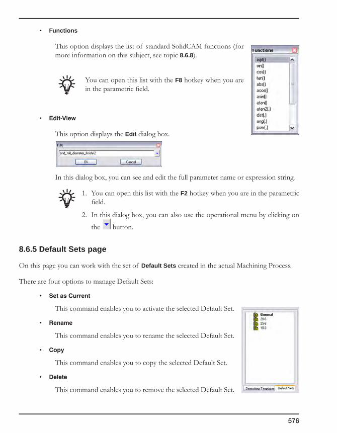
576
• Functions
This option displays the list of standard SolidCAM functions (for more information on this subject, see topic 8.6.8).
You can open this list with the F8 hotkey when you are in the parametric field.
• Edit-View
This option displays the Edit dialog box.
In this dialog box, you can see and edit the full parameter name or expression string.
1. You can open this list with the F2 hotkey when you are in the parametric field.
2. In this dialog box, you can also use the operational menu by clicking on
the button.
8.6.5 Default Sets page
On this page you can work with the set of Default Sets created in the actual Machining Process.
There are four options to manage Default Sets:
• SetasCurrent
This command enables you to activate the selected Default Set.
• Rename
This command enables you to rename the selected Default Set.
• Copy
This command enables you to copy the selected Default Set.
• Delete
This command enables you to remove the selected Default Set.

8. Machining Processes
577
You can create a number of Default Sets and assign the specific combination of values and expressions to the parameters in each of them. The Default Sets enable you to adapt the Machining Process to specific tasks.
1. Create a new Default Set with the Copy option.
2. Activate the created Default Set with the Current option.
3. Change parameters definition via Parameter Tables.
8.6.6 Parameters&Expressions Tables
There are two areas in the Machining Process Define Manager that enable you to manage your parameters and expressions:
Used Parameters Table
This area shows the table of parameters that were used in the Operation Templates with the actual Default Set.
Parameters
Default Set
Default Set
Default Set

578
This table contains the following columns:
• Parameter - this column shows the parameter name. You can change the name of the parameter. In this case the name will be updated in all Operation Templates that use this parameter.
• Expression - this column shows the parameter definition as an expression or a value. To edit this parametric field, use the parametric field menu available by clicking on the button.
• Result value - this column shows the result value returned by the parameter.
• G - this column shows the status of the parameter. If the status is Global - the G letter is shown. In this case the expression of this value will be the same in all Default Sets.
By right-clicking on this field, you can change the status of the parameter.
• R/O - this column shows the access status of the parameter. If the status is Read-only, the R/O letters are shown. In this case the parameter definition cannot be changed during Machining process insertion.
By right-clicking on this field, you can change the read-only status of the parameter.
• Description - this column shows your own text description of the parameter. To edit the field, use the context menu available by clicking on the button.
Unused Parameters Table
This area shows the table of parameters that were not used in the Operation Templates with the actual Default Set.
This table contains the following columns:
• Parameter - this column shows the parameter name. In this field you can change the name of the parameter. In this case the name will be updated in all Operation Templates that use this parameter.
• Expression - this column shows the parameter definition as either expressions or values. To edit this parametric field, you can use the operational menu available by clicking on the button.
• Result value - this column shows the result value returned by the parameter.
8. Machining Processes
579
8.6.7 Add new parameter
This field enables you to add a new parameter.
1. Choose the new parameter type from the list.
2. Type the parameter name.
3. Click the Add button to enter the parameter to the table.
The Delete button enables you to delete the selected parameter item from the Unused Parameters table.
8.6.8 Variables and expressions
SolidCAM enables you to use variables and expressions in your Operation templates.
Part Parameters
SolidCAM enables you to use a set of the standard built-in variables. All these variables get their values from the SolidCAM CAM-Part when you insert the Machining Process.
• clearance_plane – the Z-value of the Clearance Level.
• safety – the Z-value of the Safety Distance.
• tool_start_plane – the Z-value of the Tool Start Level.
• work_upper_plane – the Z-value of the CAM-Part Upper Level.
• work_lower_plane – the Z-value of the CAM-Part Lower Level.
• zero_plane – the Z-value of the Zero Level.
User-defined parameters
You can define your own variables and use it in Operation Templates definition.
SolidCAM supports the following types of variables:
Profile Geometry variables are available for Profile Operation Templates.
Slot Geometry variables are available for Slot Operation Templates.
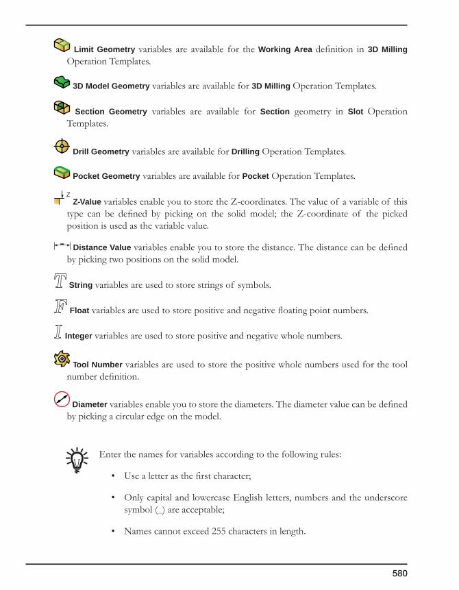
580
Limit Geometry variables are available for the Working Area definition in 3D Milling Operation Templates.
3D Model Geometry variables are available for 3D Milling Operation Templates.
Section Geometry variables are available for Section geometry in Slot Operation Templates.
Drill Geometry variables are available for Drilling Operation Templates.
Pocket Geometry variables are available for Pocket Operation Templates.
Z Z-Value variables enable you to store the Z-coordinates. The value of a variable of this
type can be defined by picking on the solid model; the Z-coordinate of the picked position is used as the variable value.
Distance Value variables enable you to store the distance. The distance can be defined by picking two positions on the solid model.
String variables are used to store strings of symbols.
Float variables are used to store positive and negative floating point numbers.
Integer variables are used to store positive and negative whole numbers.
Tool Number variables are used to store the positive whole numbers used for the tool number definition.
Diameter variables enable you to store the diameters. The diameter value can be defined by picking a circular edge on the model.
Enter the names for variables according to the following rules:
• Use a letter as the first character;
• Only capital and lowercase English letters, numbers and the underscore symbol (_) are acceptable;
• Names cannot exceed 255 characters in length.
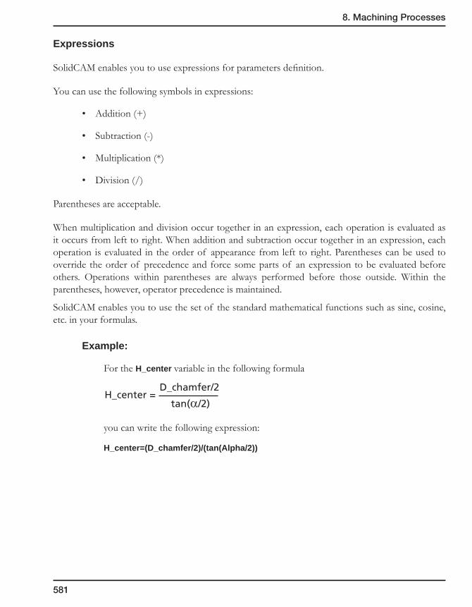
8. Machining Processes
581
Expressions
SolidCAM enables you to use expressions for parameters definition.
You can use the following symbols in expressions:
• Addition (+)
• Subtraction (-)
• Multiplication (*)
• Division (/)
Parentheses are acceptable.
When multiplication and division occur together in an expression, each operation is evaluated as it occurs from left to right. When addition and subtraction occur together in an expression, each operation is evaluated in the order of appearance from left to right. Parentheses can be used to override the order of precedence and force some parts of an expression to be evaluated before others. Operations within parentheses are always performed before those outside. Within the parentheses, however, operator precedence is maintained.
SolidCAM enables you to use the set of the standard mathematical functions such as sine, cosine, etc. in your formulas.
Example:
For the H_center variable in the following formula
you can write the following expression:
H_center=(D_chamfer/2)/(tan(Alpha/2))
H_center =D_chamfer/2
tan(α/2)

582
SolidCAM standard functions
sqrt()
Returns a value specifying the square root of a number.
sin()
Returns a value specifying the sine of an angle.
cos()
Returns a value specifying the cosine of an angle.
tan()
Returns a value specifying the tangent of an angle.
abs()
Returns a value of the same type that is passed to it specifying the absolute value of a number.
The absolute value of a number is its unsigned magnitude. For example, abs(-1) and abs(1) both return 1.
acos()
Returns a value specifying the arccosine of a number.
asin()
Returns a value specifying the arcsine of a number.
atan()
Returns a value specifying the arctangent of a number.
atan2(,)
Returns a value specifying the arctangent of quotient first and second arguments.
dist(,) and ang(,)
Returns polar coordinates: distance and angle (in radians) of the point defined in Cartesian coordinates.
(X,Y)
dist(X,Y)
0
ang(X,Y)

8. Machining Processes
583
pow(,)
Returns a value of the first argument raised to the power of the second argument.
For example: pow(2,3) returns 8.
log10()
Returns a value specifying the base-10 logarithms of a number.
ln()
Returns a value specifying the natural logarithm of a number.
sum3( , , )
Returns the sum value of three arguments.
int()
Returns the integer portion of a number.
rad()
Converts degrees to radians.
deg()
Converts radians to degrees.

584
8.6.9 Parametric tool definition
SolidCAM enables you to define the tool number as a variable, similar to the other tool data that can be defined parametrically in the Operation templates. The expression for the tool number variable can vary in the different Default sets. The tool number variable is assigned its value during the insertion of a MP into the CAM-Part.
By default, this option is disabled when you define the tool for an operation template in a MP. To enable it and define the tool number parametrically, right-click on the tool name in the Tool list area of the Part Tool table and choose Used in Current or Part Table.
The Tool number field becomes available for parametric definition. All other tool parameters are disabled.
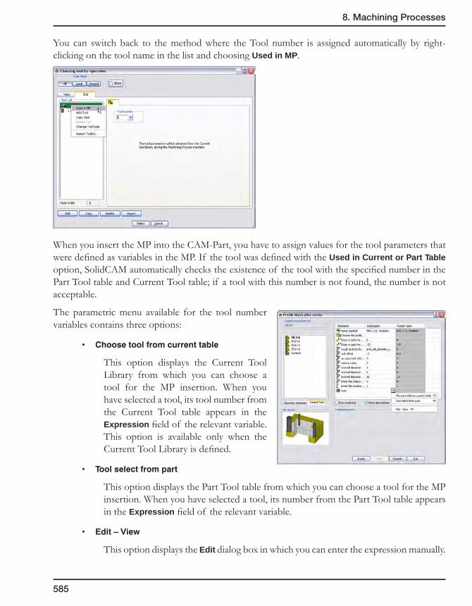
8. Machining Processes
585
You can switch back to the method where the Tool number is assigned automatically by right-clicking on the tool name in the list and choosing Used in MP.
When you insert the MP into the CAM-Part, you have to assign values for the tool parameters that were defined as variables in the MP. If the tool was defined with the Used in Current or Part Table option, SolidCAM automatically checks the existence of the tool with the specified number in the Part Tool table and Current Tool table; if a tool with this number is not found, the number is not acceptable.
The parametric menu available for the tool number variables contains three options:
• Choosetoolfromcurrenttable
This option displays the Current Tool Library from which you can choose a tool for the MP insertion. When you have selected a tool, its tool number from the Current Tool table appears in the Expression field of the relevant variable. This option is available only when the Current Tool Library is defined.
• Toolselectfrompart
This option displays the Part Tool table from which you can choose a tool for the MP insertion. When you have selected a tool, its number from the Part Tool table appears in the Expression field of the relevant variable.
• Edit–View
This option displays the Edit dialog box in which you can enter the expression manually.
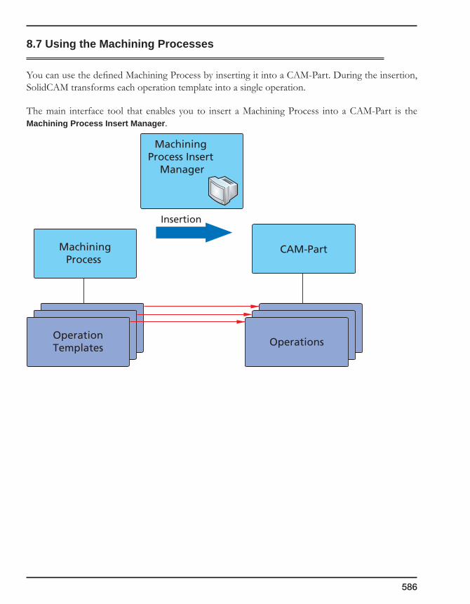
586
8.7 Using the Machining Processes
You can use the defined Machining Process by inserting it into a CAM-Part. During the insertion, SolidCAM transforms each operation template into a single operation.
The main interface tool that enables you to insert a Machining Process into a CAM-Part is the Machining Process Insert Manager.
Machining Process Insert
Manager
MachiningProcess
CAM-Part
OperationTemplates Operations
Insertion
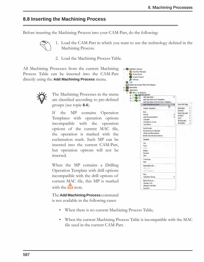
8. Machining Processes
587
8.8 Inserting the Machining Process
Before inserting the Machining Process into your CAM-Part, do the following:
1. Load the CAM-Part in which you want to use the technology defined in the Machining Process.
2. Load the Machining Process Table.
All Machining Processes from the current Machining Process Table can be inserted into the CAM-Part directly using the Add Machining Process menu.
The Machining Processes in the menu are classified according to pre-defined groups (see topic 8.4).
If the MP contains Operation Templates with operation options incompatible with the operation options of the current MAC file, the operation is marked with the exclamation mark. Such MP can be inserted into the current CAM-Part, but operation options will not be inserted.
When the MP contains a Drilling Operation Template with drill options incompatible with the drill options of current MAC file, this MP is marked with the ! icon.
The Add Machining Process command is not available in the following cases:
• When there is no current Machining Process Table;
• When the current Machining Process Table is incompatible with the MAC file used in the current CAM-Part.

588
When the Machining process is chosen, the Machining Process Insert Manager is displayed.
The From MP Table command enables you to choose the Machining Process to insert from the Machining Process Table Manager dialog box.
The Machining Process Table Manager is displayed.
Choose a Machining Process from the list. Click on the Pick button. The Machining Process Insert Manager is displayed.
While the Insert Manager is loading, SolidCAM receives necessary information from the CAM-Part. Then SolidCAM receives expressions for other parameters from the current Default Set and calculates them.
To prepare the Machining Process for insertion, do the following:
1. On the Default Sets page, choose the required Default Set.
2. With the Parameters Table, fill all the blank expression fields. You can also change all expressions that do not have Read-Only status.
3. When the Machining Process is defined, click on the Insert button to insert the Machining Process into the current CAM-Part.
4. SolidCAM chooses tools for the Machining Process.
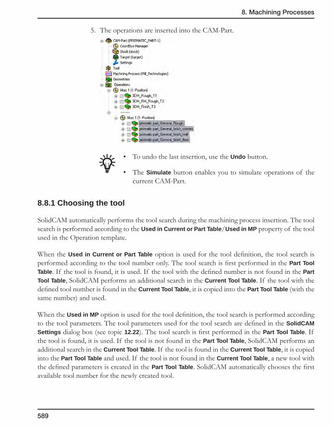
8. Machining Processes
589
5. The operations are inserted into the CAM-Part.
• To undo the last insertion, use the Undo button.
• The Simulate button enables you to simulate operations of the current CAM-Part.
8.8.1 Choosing the tool
SolidCAM automatically performs the tool search during the machining process insertion. The tool search is performed according to the Used in Current or Part Table/Used in MP property of the tool used in the Operation template.
When the Used in Current or Part Table option is used for the tool definition, the tool search is performed according to the tool number only. The tool search is first performed in the Part Tool Table. If the tool is found, it is used. If the tool with the defined number is not found in the Part Tool Table, SolidCAM performs an additional search in the Current Tool Table. If the tool with the defined tool number is found in the Current Tool Table, it is copied into the Part Tool Table (with the same number) and used.
When the Used in MP option is used for the tool definition, the tool search is performed according to the tool parameters. The tool parameters used for the tool search are defined in the SolidCAM Settings dialog box (see topic 12.22). The tool search is first performed in the Part Tool Table. If the tool is found, it is used. If the tool is not found in the Part Tool Table, SolidCAM performs an additional search in the Current Tool Table. If the tool is found in the Current Tool Table, it is copied into the Part Tool Table and used. If the tool is not found in the Current Tool Table, a new tool with the defined parameters is created in the Part Tool Table. SolidCAM automatically chooses the first available tool number for the newly created tool.

590
8.9 Machining Process Insert Manager
8.9.1 Operation Templates Page
This page displays the list of Operation Templates that were inserted into the CAM-Part.
• By clicking on the (+) sign near each Operation Template, you can see the list of parameters used in the selected Operation template.

8. Machining Processes
591
• To see the Operation Template parameters and settings, right-click on the Operation Template name in the list and choose the Show command from the list. The Operation Template dialog box will be displayed.
In this dialog box you cannot edit the Operation Template definition. To edit the Operation Template, go to the Machining Process Define Manager (see topic 8.6).
In the Operation Template screen, all parametric fields are marked with
the button. Click on this button to see the parametric field menu. The Edit-View option is available in this menu. This option opens the parameter edit dialog box.
This dialog box enables you to see and edit the full parameter name or expression string.
8.9.2 Default Sets Page
Double-click on the Default Set name to make it current. The Parameters and values from the selected Default set will be shown in the Parameters Table.

592
8.9.3 Parameters Table
There are three columns in this table:
• Parameter – shows the parameter name.
• Expression – shows the parameter definition. In this field you have to define missed expressions for parameters. You can also edit all expressions that do not have the Read-Only status.
• Result value – shows the result value returned by the parameter.
With the Show read only check box, you can allow or forbid showing parameters marked Read-Only.
The Show descriptions check box enables you to show the parameter description instead of the parameter name in the Parameter column.
8.9.4 Operation Points
This field contains buttons to define specific points of the operation.
8.9.5 Parameters definition
Click on the button to display menus for each parametric field.
Parametric field menu for Geometries
• GeomSelect
This option displays a list of geometries of a suitable type that is defined in the CAM-Part.
Choose the variable name from the list.
You can also open this list with the F5 hotkey when you are in the parametric field.
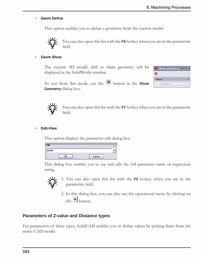
8. Machining Processes
593
• GeomDefine
This option enables you to define a geometry from the current model.
You can also open this list with the F6 hotkey when you are in the parametric field.
• GeomShow
The current 3D model, drill or chain geometry will be displayed in the SolidWorks window.
To exit from this mode, use the button in the Show Geometry dialog box.
You can also open this list with the F7 hotkey when you are in the parametric field.
• Edit-View
This option displays the parameter edit dialog box.
This dialog box enables you to see and edit the full parameter name or expression string.
1. You can also open this list with the F2 hotkey when you are in the parametric field.
2. In this dialog box, you can also use the operational menu by clicking on
the button.
Parameters of Z-value and Distance types
For parameters of these types, SolidCAM enables you to define values by picking them from the active CAD model.

594
• To define the Z-value, choose the Pick Z-value (F5) item from the parametric menu.
The Pick Z-Value dialog box will be displayed. Pick the point on the model and click on the OK button to confirm the selection.
• To define the Distance, choose the Pick Distance (F5) item from the Parametric menu.
1. In the SolidWorks window, pick the first point.
2. Confirm the selection with the OK button in the Distance: Pick first point dialog box.
3. Pick the second point and confirm it in the same way.
The Distance value will be calculated.
Other Parameters
For parameters of other types, the parametric field menu contains only one item: Edit-View (F2).
Choose it to edit the parameter definition in the Edit window.

Automatic Feature Recognitionand Machining (AFRM) 9
The SolidCAM Automatic Holes Feature Recognition and Machining (AFRM) module enables you to automatically recognize holes in the Solid model and generate the tool path for machining.
Hole Feature recognition
Preparing to machining
Feature Sets definition
Technology
Technology Database
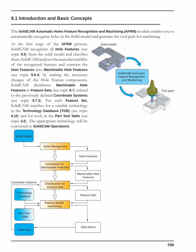
596
9.1 Introduction and Basic Concepts
The SolidCAM Automatic Holes Feature Recognition and Machining (AFRM) module enables you to automatically recognize holes in the Solid model and generate the tool path for machining.
At the first stage of the AFRM process, SolidCAM recognizes all Hole Features (see topic 9.5) from the solid model and classifies them. SolidCAM analyzes the manufacturability of the recognized features and converts the Hole Features into Machinable Hole Features (see topic 9.6.4) by making the necessary changes of the Hole Feature components. SolidCAM distributes Machinable Hole Features to Feature Sets (see topic 9.7) related to the previously defined Coordinate Systems (see topic 9.7.3). For each Feature Set, SolidCAM searches for a suitable technology in the Technology Database (TDB) (see topic 9.10) and for tools in the Part Tool Table (see topic 3.6). The appropriate technology will be converted to SolidCAM Operations.
Solid model
TechnologyDatabase
CAM-Part
Holes Recognition
Hole Features
Machinable HoleFeatures
Feature Sets
Operations
Coordinate Systems
Conversion to Machinable Features
Distribution to Feature Sets
Feature-based machining
Part Tool Table
SolidCAM Automatic Feature Recognition
and Machining
Solid model
Tool path

9. Automatic Feature Recognition and Machining
597
All the holes recognized by SolidCAM can be classified as Simple Hole Features or Compound Hole Features.
A Simple Hole Feature is a cut in the solid body generated by the figure of revolution. The diameter of a Simple Hole can be constant or changing. A Simple Hole can be Blind or Through.
Blind Simple Hole Feature Through Simple Hole Feature
A Compound Hole Feature is also generated by the cut of the figure of revolution. The diameter of the Compound Hole Feature is constant or decreasing at the start of the hole and increasing at the end of the hole. The Compound Hole Feature can be only through.
SolidCAM recognizes Disconnected Hole Features containing a number of ”broken” holes consisting of coaxial and coradial segments divided by the model elements.
SolidCAM recognizes the holes with the undercuts.
Blind Hole Feature with undercut
Compound Hole Feature with undercut Through Hole Feature with undercut
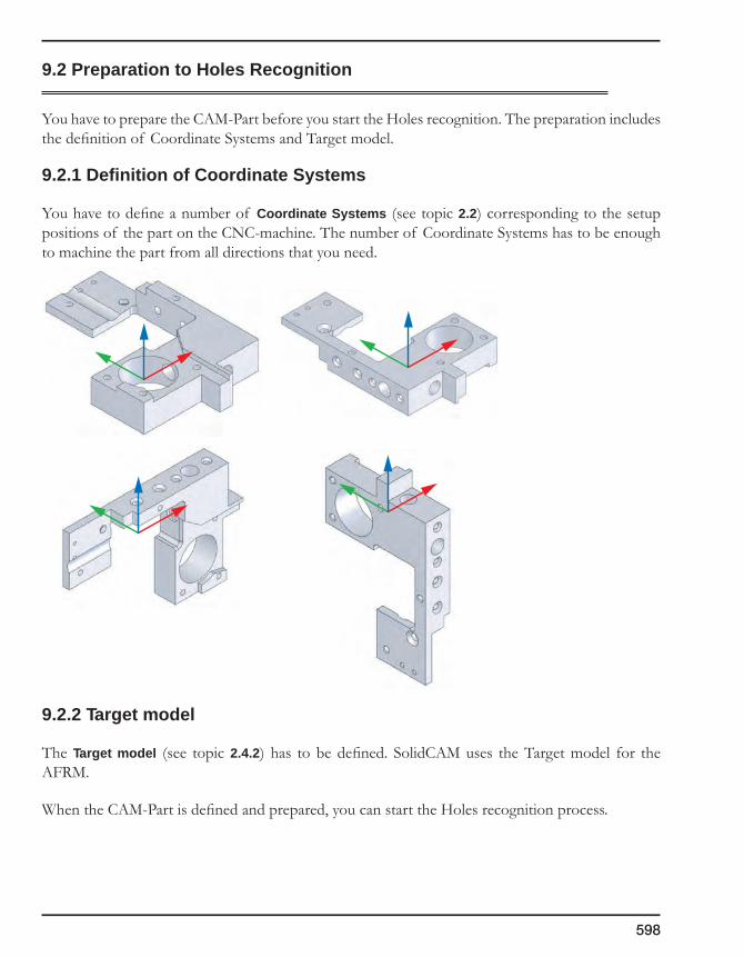
598
9.2 Preparation to Holes Recognition
You have to prepare the CAM-Part before you start the Holes recognition. The preparation includes the definition of Coordinate Systems and Target model.
9.2.1 Definition of Coordinate Systems
You have to define a number of Coordinate Systems (see topic 2.2) corresponding to the setup positions of the part on the CNC-machine. The number of Coordinate Systems has to be enough to machine the part from all directions that you need.
9.2.2 Target model
The Target model (see topic 2.4.2) has to be defined. SolidCAM uses the Target model for the AFRM.
When the CAM-Part is defined and prepared, you can start the Holes recognition process.
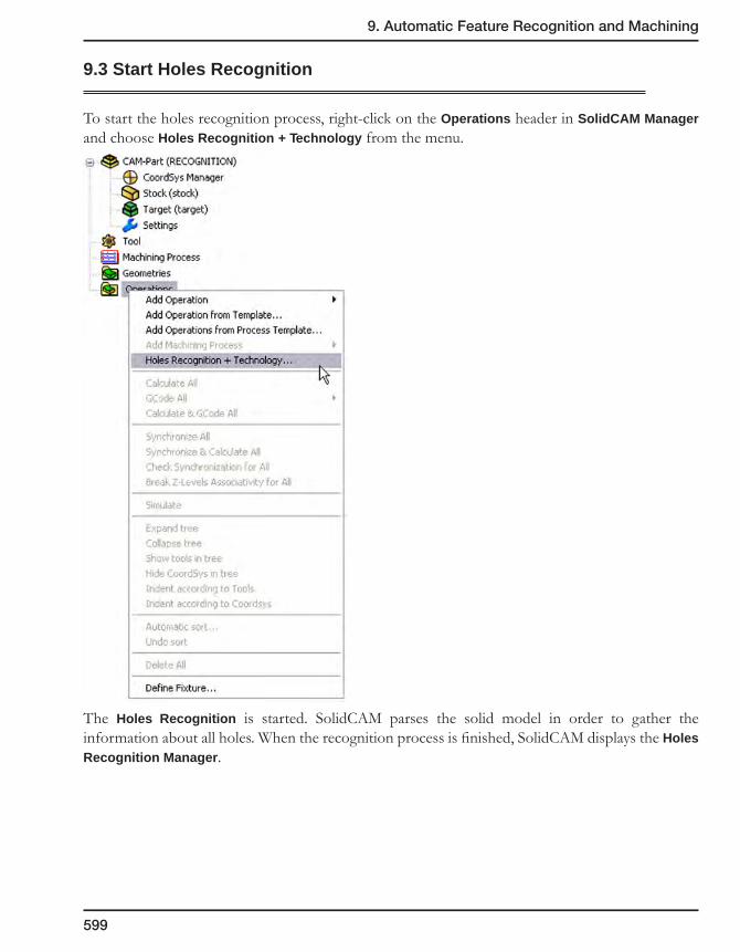
9. Automatic Feature Recognition and Machining
599
9.3 Start Holes Recognition
To start the holes recognition process, right-click on the Operations header in SolidCAM Manager and choose Holes Recognition + Technology from the menu.
The Holes Recognition is started. SolidCAM parses the solid model in order to gather the information about all holes. When the recognition process is finished, SolidCAM displays the Holes Recognition Manager.
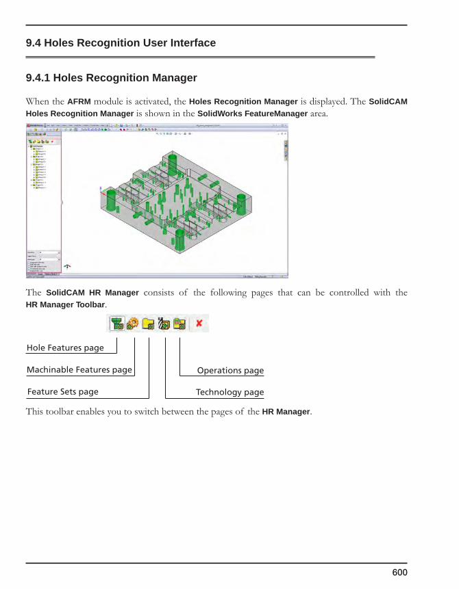
600
9.4 Holes Recognition User Interface
9.4.1 Holes Recognition Manager
When the AFRM module is activated, the Holes Recognition Manager is displayed. The SolidCAM Holes Recognition Manager is shown in the SolidWorks FeatureManager area.
The SolidCAM HR Manager consists of the following pages that can be controlled with theHR Manager Toolbar.
This toolbar enables you to switch between the pages of the HR Manager.
Hole Features page
Machinable Features page
Feature Sets page Technology page
Operations page
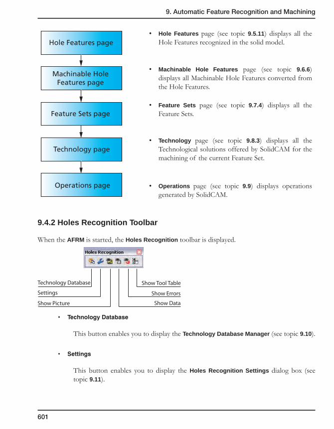
9. Automatic Feature Recognition and Machining
601
Hole Features page
Machinable Hole Features page
Feature Sets page
Technology page
Operations page
• Hole Features page (see topic 9.5.11) displays all the Hole Features recognized in the solid model.
• Machinable Hole Features page (see topic 9.6.6) displays all Machinable Hole Features converted from the Hole Features.
• Feature Sets page (see topic 9.7.4) displays all the Feature Sets.
• Technology page (see topic 9.8.3) displays all the Technological solutions offered by SolidCAM for the machining of the current Feature Set.
• Operations page (see topic 9.9) displays operations generated by SolidCAM.
9.4.2 Holes Recognition Toolbar
When the AFRM is started, the Holes Recognition toolbar is displayed.
• TechnologyDatabase
This button enables you to display the Technology Database Manager (see topic 9.10).
• Settings
This button enables you to display the Holes Recognition Settings dialog box (see topic 9.11).
Technology Database
Settings
Show Data
Show Errors
Show Tool Table
Show Picture

602
• ShowPicture
This button enables you to display the schematic picture of the selected item.
• ShowData
This button enables you to display the Parameters dialog box that displays the parameters of the selected item.
• ShowErrors
This button enables you to display the Errors dialog box that shows the errors that occurred during the AFRM process.
• ShowToolTable
This button enables you to display the Part Tool Table.
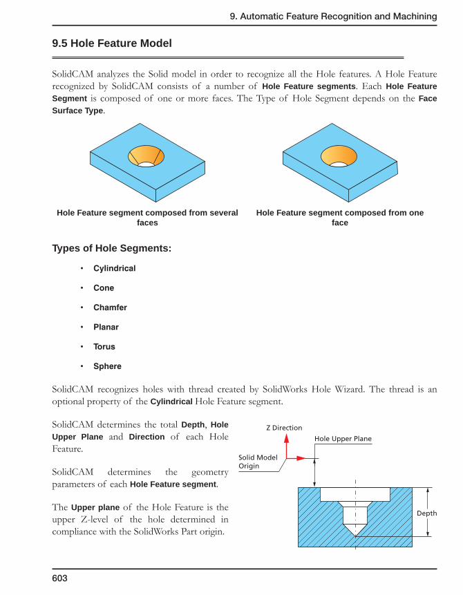
9. Automatic Feature Recognition and Machining
603
9.5 Hole Feature Model
SolidCAM analyzes the Solid model in order to recognize all the Hole features. A Hole Feature recognized by SolidCAM consists of a number of Hole Feature segments. Each Hole Feature Segment is composed of one or more faces. The Type of Hole Segment depends on the Face Surface Type.
Hole Feature segment composed from several faces
Hole Feature segment composed from one face
Types of Hole Segments:
• Cylindrical
• Cone
• Chamfer
• Planar
• Torus
• Sphere
SolidCAM recognizes holes with thread created by SolidWorks Hole Wizard. The thread is an optional property of the Cylindrical Hole Feature segment.
SolidCAM determines the total Depth, Hole Upper Plane and Direction of each Hole Feature.
SolidCAM determines the geometry parameters of each Hole Feature segment.
The Upper plane of the Hole Feature is the upper Z-level of the hole determined in compliance with the SolidWorks Part origin.
Solid ModelOrigin
Z Direction
Hole Upper Plane
Depth
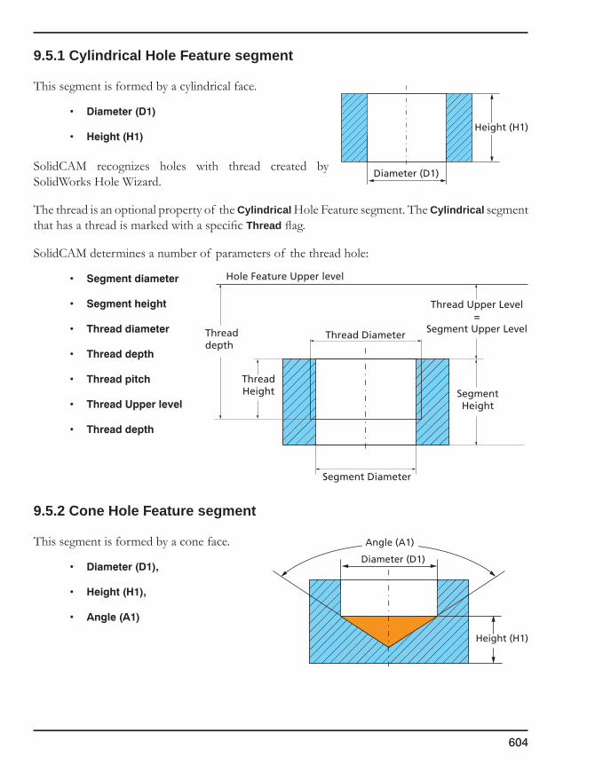
604
9.5.1 Cylindrical Hole Feature segment
This segment is formed by a cylindrical face.
• Diameter(D1)
• Height(H1)
SolidCAM recognizes holes with thread created by SolidWorks Hole Wizard.
The thread is an optional property of the Cylindrical Hole Feature segment. The Cylindrical segment that has a thread is marked with a specific Thread flag.
SolidCAM determines a number of parameters of the thread hole:
• Segmentdiameter
• Segmentheight
• Threaddiameter
• Threaddepth
• Threadpitch
• ThreadUpperlevel
• Threaddepth
9.5.2 Cone Hole Feature segment
This segment is formed by a cone face.
• Diameter(D1),
• Height(H1),
• Angle(A1)
Diameter (D1)
Height (H1)
Segment Diameter
Thread Diameter
Hole Feature Upper level
ThreadHeight Segment
Height
Threaddepth
Thread Upper Level=
Segment Upper Level
Diameter (D1)
Height (H1)
Angle (A1)

9. Automatic Feature Recognition and Machining
605
9.5.3 Chamfer Hole Feature segment
This segment is formed by a truncated conical face.
• Upperdiameter(D1),
• Lowerdiameter(D2),
• Height(H1),
• Angle(A1)
9.5.4 Planar Hole Feature segment
This segment is formed by a planar face. A segment of this type has no parameters.
9.5.5 Torus Hole Feature segment
• UpperDiameter(D1)
• LowerDiameter(D2)
• Height(H1)
• Radius(R1)
There are two parameters describing the location of the center of the generatrix circle:
• HC - Height of the center relative to the bottom of the torus.
• DC - Diameter of the center.
Upper Diameter (D1)
Lower Diameter (D2)
Height(H1)
Angle (A1)
Upper Diameter (D1)
Lower Diameter (D2)
Height(H1)
Radius(R1)
Diameter of the center (DC)
Height of the center (HC)Radius (R1)
Torussegments
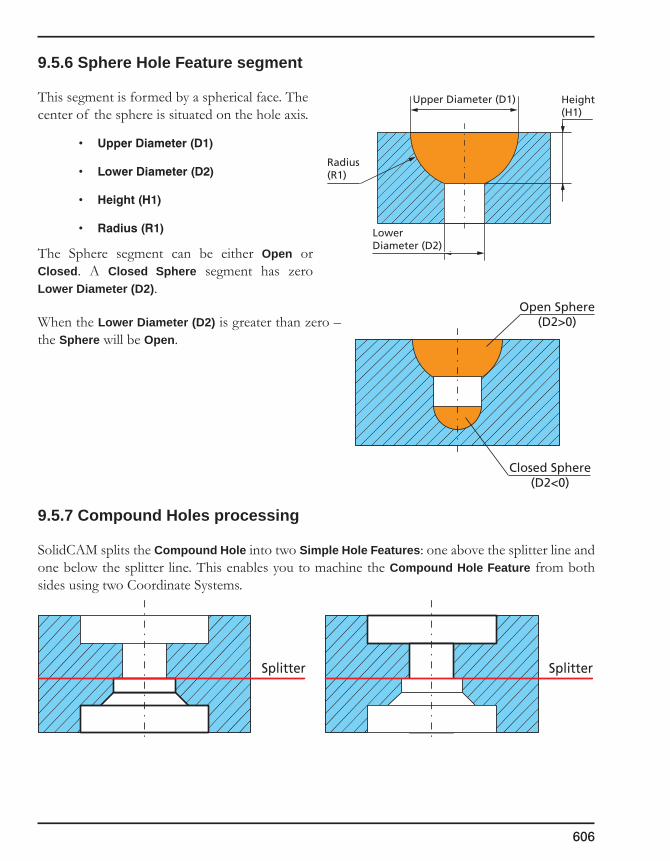
606
9.5.6 Sphere Hole Feature segment
This segment is formed by a spherical face. The center of the sphere is situated on the hole axis.
• UpperDiameter(D1)
• LowerDiameter(D2)
• Height(H1)
• Radius(R1)
The Sphere segment can be either Open or Closed. A Closed Sphere segment has zero Lower Diameter (D2).
When the Lower Diameter (D2) is greater than zero – the Sphere will be Open.
9.5.7 Compound Holes processing
SolidCAM splits the Compound Hole into two Simple Hole Features: one above the splitter line and one below the splitter line. This enables you to machine the Compound Hole Feature from both sides using two Coordinate Systems.
Open Sphere(D2>0)
Closed Sphere(D2<0)
Upper Diameter (D1)
Lower Diameter (D2)
Height(H1)
Radius(R1)
Splitter Splitter

9. Automatic Feature Recognition and Machining
607
9.5.8 Disconnected Holes processing
Sometimes solid models contain a number of ”broken” holes consisting of coaxial and coradial segments divided by the model elements. Previously these segments were recognized and machined as separate Hole Features. The AFRM module enables you to automatically connect these segments into one single Connected Hole Feature (see topic 9.11.1).
9.5.9 Reaming recognition
The AFRM module enables you to automatically recognize holes in solid models and perform their precise machining by reaming technology.
If during the Hole Feature recognition SolidCAM finds a combination of Cylinder-Planar-Cylinder Hole Feature segments, and the difference between the diameters of the Upper Cylinder and Lower Cylinder is smaller than 0.2 mm, SolidCAM recognizes Upper Cylinder and Planar segments as precise hole suitable for applying the reaming technology.
The Reaming Diameter and Reaming Height parameters are determined as shown below.
9.5.10 Hole Feature Shapes and Groups
The SolidCAM AFRM module classifies the Hole Features into Hole Feature Shapes and Hole Feature Groups.
The Hole Features with the same type and sequence of segments will be included into one Hole Feature Shape.
Upper Cylinder
Lower Cylinder
Planar segment
Reaming diameter
Reaming Height
Reaming DepthReaming Upper Level
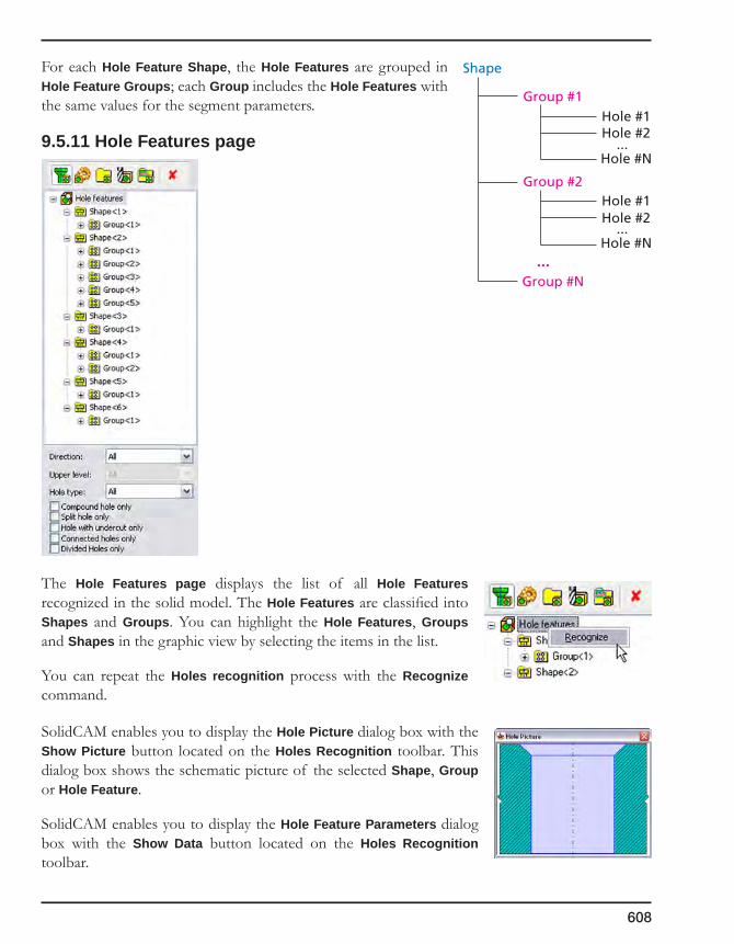
608
For each Hole Feature Shape, the Hole Features are grouped in Hole Feature Groups; each Group includes the Hole Features with the same values for the segment parameters.
9.5.11 Hole Features page
The Hole Features page displays the list of all Hole Features recognized in the solid model. The Hole Features are classified into Shapes and Groups. You can highlight the Hole Features, Groups and Shapes in the graphic view by selecting the items in the list.
You can repeat the Holes recognition process with the Recognize command.
SolidCAM enables you to display the Hole Picture dialog box with the Show Picture button located on the Holes Recognition toolbar. This dialog box shows the schematic picture of the selected Shape, Group or Hole Feature.
SolidCAM enables you to display the Hole Feature Parameters dialog box with the Show Data button located on the Holes Recognition toolbar.
Shape
Group #1
Group #2
Hole #1Hole #2
...Hole #N
Hole #1Hole #2
...
...Hole #N
Group #N
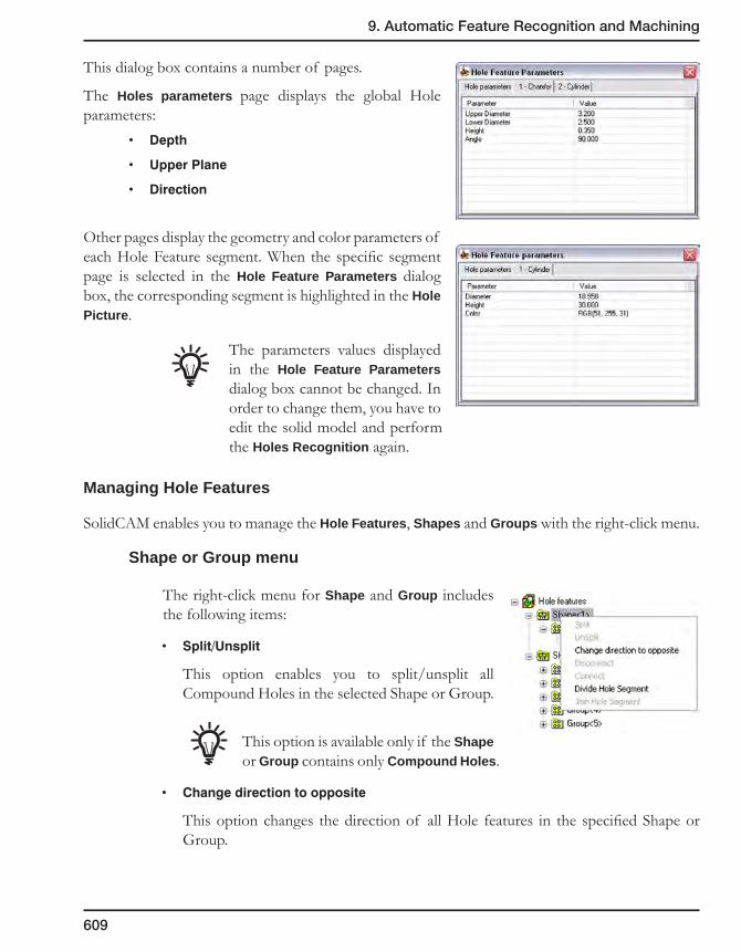
9. Automatic Feature Recognition and Machining
609
This dialog box contains a number of pages.
The Holes parameters page displays the global Hole parameters:
• Depth
• UpperPlane
• Direction
Other pages display the geometry and color parameters of each Hole Feature segment. When the specific segment page is selected in the Hole Feature Parameters dialog box, the corresponding segment is highlighted in the Hole Picture.
The parameters values displayed in the Hole Feature Parameters dialog box cannot be changed. In order to change them, you have to edit the solid model and perform the Holes Recognition again.
Managing Hole Features
SolidCAM enables you to manage the Hole Features, Shapes and Groups with the right-click menu.
Shape or Group menu
The right-click menu for Shape and Group includes the following items:
• Split/Unsplit
This option enables you to split/unsplit all Compound Holes in the selected Shape or Group.
This option is available only if the Shape or Group contains only Compound Holes.
• Changedirectiontoopposite
This option changes the direction of all Hole features in the specified Shape or Group.

610
• Connect
This option enables you to connect appropriate broken segments into one single Connected Hole Feature (see topic 9.11.1).
• Disconnect
This option enables you to divide a Connected Hole Feature into separate segments (see topic 9.11.1).
• Divide/Joinholesegment
This option enables you to machine cylindrical through holes with depth significantly greater than a normal cutting length of a tool. Such holes are divided into two halves so that they can be approached by the tool from both sides and machined with an overlap of 10% from the entire hole depth.
Divided holes can be joined.
Hole Feature menu
The right-click menu for Hole Features includes the following items:
• Split/Unsplit
This option enables you to split/unsplit the selected Compound Hole.
This option is available only for Compound Holes.
Overlap

9. Automatic Feature Recognition and Machining
611
• Changedirectiontoopposite
This option changes the direction of the selected Hole Feature.
• Connect
This option enables you to connect appropriate “broken” segments into one single Connected Hole Feature (see topic 9.11.1).
• Disconnect
This option enables you to disconnect a Connected Hole Feature into separate segments (see topic 9.11.1).
• Divide/Joinholesegment
This option enables you to machine cylindrical through holes with depth significantly greater than a normal cutting length of a tool. Such holes are divided into two halves so that they can be approached by the tool from both sides and machined with an overlap of 10% from the entire hole depth.
Divided holes can be joined.
• GotoOpposite
This option enables you to jump in the list to the opposite part of the Split Compound Hole.
This option is available only for Split Compound Holes.
Hole Features filter
The filter capabilities enable you to display in the list only those Hole Features that correspond to a certain criterion.
• Directionfilter
This filter enables you to display Hole Features with a specified direction only.
• Upperlevelfilter
This filter enables you to display Hole Features with a specified Upper Level only.
The Upper Level filter is active only for the specified direction.
612
• Holetypefilter
This filter enables you to display Hole Features of a specified type: either Blind or Through.
• Compoundholeonly
This option enables you to display only the compound holes.
• Splitholeonly
This option enables you to display only the split holes.
• Holewithundercutonly
This option enables you to display only the Hole Features with undercut.
• Connectedholesonly
This option enables you to show/hide the Connected Hole Features (see topic 9.11.1).
• Dividedholesonly
This option enables you to display only the divided holes.

9. Automatic Feature Recognition and Machining
613
9.6 Preparing Hole Features for machining
There are following stages of preparing Hole Features for machining:• Undercutprocessing
• SegmentsUnion
• CreatingMachinableHoleFeatures
9.6.1 Undercut processing
SolidCAM recognizes undercuts in the Hole Feature model.
The SolidCAM AFRM Module analyzes Hole Feature segments in order to find an undercut. An undercut is detected when the diameter increases during one topology segment. The Undercut consists of a number of segments and finishes when the current diameter is equal to the undercut initial diameter.
SolidCAM determines the Undercut Height (HU) as the sum of the height of all topology segments of the undercut.
SolidCAM classifies undercuts depending on the last Hole Feature segment included in undercut. The classification is as follows:
• Undercut – None
In this case the finish diameter of the last segment of the undercut is equal to the Undercut diameter.
• Undercut – Planar
In this case Undercut finishes with the Planar Hole Feature segment (see topic 9.5.4).
• Undercut – Cone
In this case Undercut finishes with the Cone Hole Feature segment (see topic 9.5.2).
UndercutHeight (HU)
Undercut Diameter (DU)
Undercut

614
• Undercut – Chamfer
In this case Undercut finishes with the Chamfer Hole Feature segment (see topic 9.5.3).
• Undercut – Torus
In this case Undercut finishes with the Torus Hole Feature segment (see topic 9.5.5).
• Undercut – Sphere
In this case Undercut finishes with the Sphere Hole Feature segment (see topic 9.5.6).
9.6.2 Undercut substitution
SolidCAM handles undercuts by substituting the undercut with a cylindrical segment depending on the undercut type. The cylinder diameter is equal to the Undercut diameter (DU). When a part of the lower undercut segment is smaller than the Undercut diameter, SolidCAM substitutes this part with a cone, chamfer, torus or sphere segment.
Undercut substitution schemes:
• Undercut – None segment substitution
• Undercut – Planar segment substitution
HU
H1=HUD1=DU
Height (H1)
DU Diameter (D1)
HU
H1=HUD1=DU
Height (H1)
DU Diameter (D1)
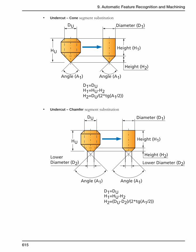
9. Automatic Feature Recognition and Machining
615
• Undercut – Cone segment substitution
• Undercut – Chamfer segment substitution
HU
H1=HU-H2H2=(DU-D2)/(2*tg(A1/2))
D1=DU
Height (H1)
Height (H2)
DU Diameter (D1)
Angle (A1)
LowerDiameter (D2) Lower Diameter (D2)
Angle (A1)
HU
H1=HU-H2H2=DU/(2*tg(A1/2))
D1=DU
Height (H1)
Height (H2)
DU Diameter (D1)
Angle (A1) Angle (A1)
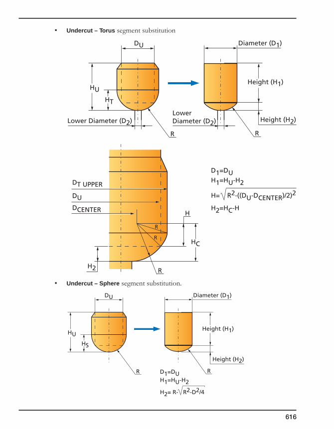
616
• Undercut – Torus segment substitution
• Undercut – Sphere segment substitution.
HU
HT
R
H1=HU-H2
H2=HC-H
H= R2-((DU-DCENTER)/2)2
D1=DU
Height (H1)
Height (H2)
DU Diameter (D1)
Lower Diameter (D2)LowerDiameter (D2)
R
DT UPPER
DU
R
R
R
DCENTER
H2
HC
H
HU
HS
RH1=HU-H2
H2= R- R2-D2/4
D1=DU
Height (H1)
Height (H2)
DU Diameter (D1)
R

9. Automatic Feature Recognition and Machining
617
9.6.3 Segments Union
SolidCAM enables you to unite identical adjacent Hole Feature segments.
There are the following cases for union:
• Planar+Planar
• Cylinder+Cylinder
The diameter of the resulting cylinder will be the same as the diameter of the original cylinders. The Height will be the sum of the original cylinder heights.
• Chamfer+Cone
The Diameter of the resulting cone will be the same as the Diameter of the original upper chamfer. The Angle of the resulting segment is equal to the Angle of the original cones. The Height will be the sum of the original cone heights.
Planar 1
Planar 2
United Planar
Cylinder 1
Cylinder 2
United Cylinder
Chamfer
Cone
United Cone

618
• Chamfer+Chamfer
The Upper Diameter of the resulting chamfer segment will be the same as the Upper Diameter of the original upper chamfer. The Angle of the resulting segment is equal to the Angle of the original chamfers. The Lower Diameter of the resulting chamfer segment will be the same as the Lower Diameter of the original lower chamfer. The Height will be the sum of the original chamfer heights.
• Torus+Torus
The Upper Diameter of the resulting torus segment will be the same as the Upper Diameter of the original upper torus. The Radius of the resulting segment is equal to the Radius of the original torus. The Lower Diameter of the resulting torus segment will be the same as the Lower Diameter of the original lower torus. The Height will be the sum of the original torus heights.
• Sphere+Sphere
The Upper Diameter of the resulting sphere segment will be the same as the Upper Diameter of the original upper sphere. The Radius of the resulting segment is equal to the Radius of the original spheres. The Lower Diameter of the resulting sphere segment will be the same as the Lower Diameter of the original lower sphere. The Height will be the sum of the original sphere heights.
Chamfer 1
Chamfer 2
United Chamfer
Torus 1
Torus 2
United Torus
Sphere 1
Sphere 2
United Sphere

9. Automatic Feature Recognition and Machining
619
9.6.4 Machinable Hole Features
SolidCAM converts Hole Features into the Machinable Hole Features in order to prepare them for machining. The Machinable Hole Feature consists of one or more Machinable Hole Feature segments that can be machined in one operation with the same tool.
Types of Machinable Hole Feature segments
The following types of the Machinable Hole Feature segments exist:
• Drill
• Chamfer
• Flat Cylinder
• Flat Chamfer
• Thread
• Reaming
Parameters of Machinable Hole Feature segments
SolidCAM calculates the values of various parameters for the Machinable Hole Feature segments. These parameters are called HR variables. They will be used later for the technology definition.
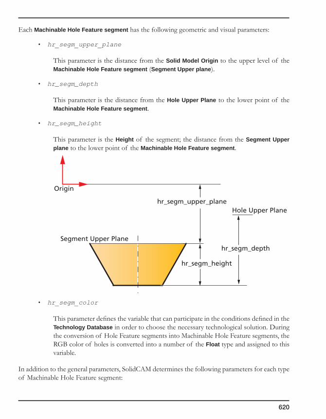
620
Each Machinable Hole Feature segment has the following geometric and visual parameters:
• hr_segm_upper_plane
This parameter is the distance from the Solid Model Origin to the upper level of the Machinable Hole Feature segment (Segment Upper plane).
• hr_segm_depth
This parameter is the distance from the Hole Upper Plane to the lower point of the Machinable Hole Feature segment.
• hr_segm_height
This parameter is the Height of the segment; the distance from the Segment Upper plane to the lower point of the Machinable Hole Feature segment.
• hr_segm_color
This parameter defines the variable that can participate in the conditions defined in the Technology Database in order to choose the necessary technological solution. During the conversion of Hole Feature segments into Machinable Hole Feature segments, the RGB color of holes is converted into a number of the Float type and assigned to this variable.
In addition to the general parameters, SolidCAM determines the following parameters for each type of Machinable Hole Feature segment:
Segment Upper Plane
Hole Upper Plane
Origin
hr_segm_height
hr_segm_upper_plane
hr_segm_depth
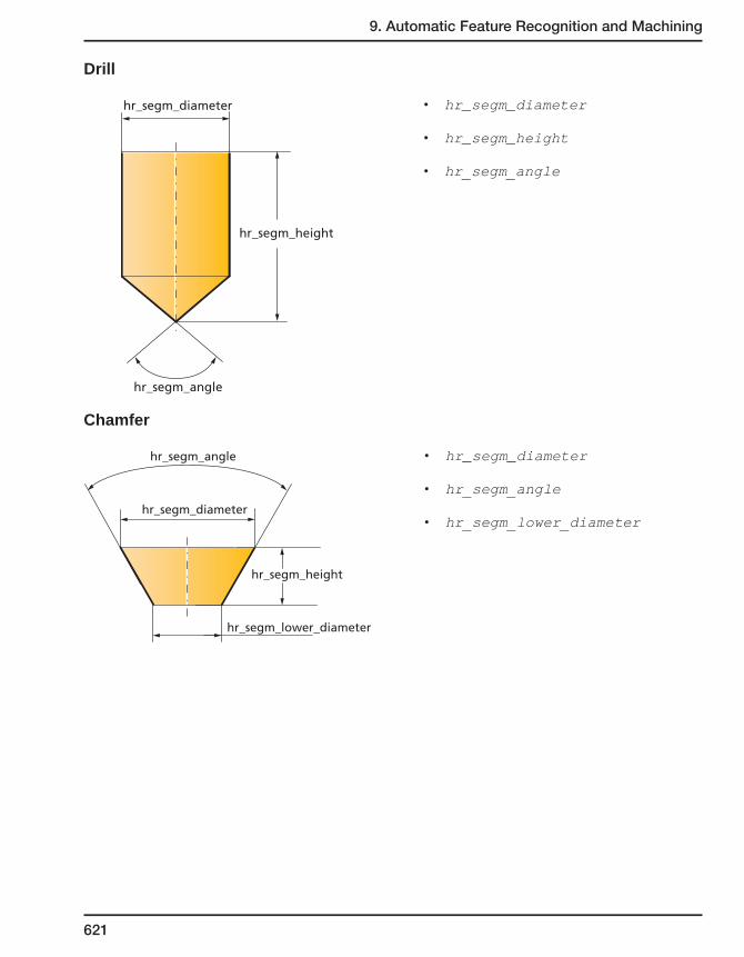
9. Automatic Feature Recognition and Machining
621
Drill
hr_segm_diameter
hr_segm_height
hr_segm_angle
• hr_segm_diameter
• hr_segm_height
• hr_segm_angle
Chamfer
hr_segm_height
hr_segm_diameter
hr_segm_angle
hr_segm_lower_diameter
• hr_segm_diameter
• hr_segm_angle
• hr_segm_lower_diameter

622
Flat Cylinder
hr_segm_height
hr_segm_height
hr_segm_diameter
hr_segm_diameter
hr_prev_segm_diameter
hr_segm_blind = true
hr_segm_blind = false
• hr_segm_diameter
• hr_segm_blind
• hr_prev_segm_diameter
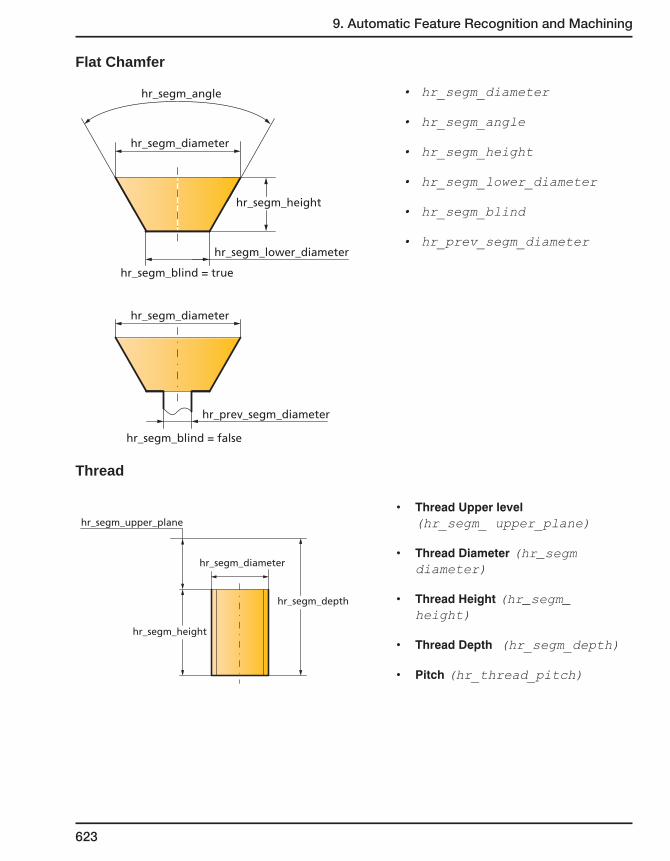
9. Automatic Feature Recognition and Machining
623
Flat Chamfer
hr_segm_height
hr_segm_diameter
hr_segm_diameter
hr_prev_segm_diameter
hr_segm_angle
hr_segm_blind = true
hr_segm_blind = false
hr_segm_lower_diameter
• hr_segm_diameter
• hr_segm_angle
• hr_segm_height
• hr_segm_lower_diameter
• hr_segm_blind
• hr_prev_segm_diameter
Thread
hr_segm_height
hr_segm_diameter
hr_segm_depth
hr_segm_upper_plane• ThreadUpperlevel
(hr_segm_ upper_plane)
• ThreadDiameter(hr_segm diameter)
• ThreadHeight(hr_segm_height)
• ThreadDepth (hr_segm_depth)
• Pitch(hr_thread_pitch)

624
Reaming
hr_segm_height
hr_segm_diameter
hr_segm_depth
hr_segm_upper_plane • ReamingUpperlevel (hr_segm_ upper_plane)
• ReamingDiameter (hr_segm diameter)
• ReamingHeight (hr_segm_height)
• ReamingDepth (hr_segm_depth)
For the Machinable Hole Feature segments containing cylinder (Drill and Flat Cylinder), the Hole Upper Plane is coincident with the Segment Upper Plane. Therefore, the hr_segm_height is equal to the hr_segm_depth.
hr_segm_height = hr_segm_depth
Segment Upper Plane = Hole Upper Plane
hr_segm_upper_plane
Origin
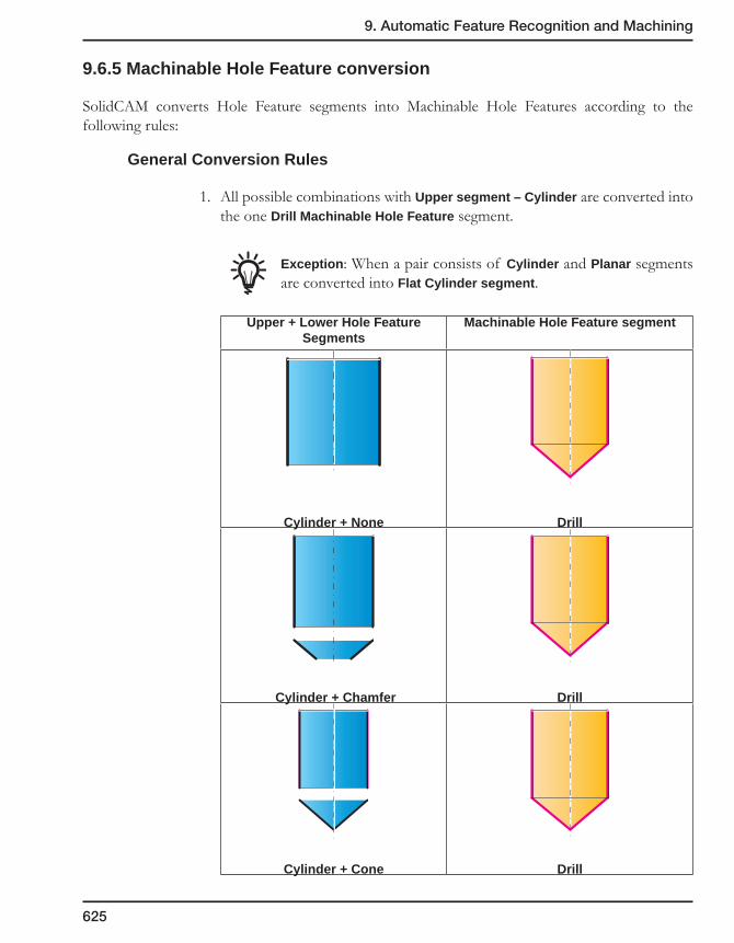
9. Automatic Feature Recognition and Machining
625
9.6.5 Machinable Hole Feature conversion
SolidCAM converts Hole Feature segments into Machinable Hole Features according to the following rules:
General Conversion Rules
1. All possible combinations with Upper segment – Cylinder are converted into the one Drill Machinable Hole Feature segment.
Exception: When a pair consists of Cylinder and Planar segments are converted into Flat Cylinder segment.
Upper + Lower Hole Feature Segments
Machinable Hole Feature segment
Cylinder + None Drill
Cylinder + Chamfer Drill
Cylinder + Cone Drill

626
Cylinder + Torus (open Sphere) Drill
Cylinder + Sphere Drill
2. Cone and Closed Sphere segments are converted into a Drill Machinable Hole Feature segment.
Hole Feature segment Machinable Hole Feature segment
Cone Drill
Closed Sphere Drill

9. Automatic Feature Recognition and Machining
627
3. All possible combinations with Lower segment – Planar are converted into one Machinable Hole Feature segment.
Upper + Lower Hole Feature Segments
Machinable Hole Feature segment
Cylinder + Planar Flat Cylinder
Chamfer + Planar Flat Chamfer
Torus/Open Sphere + Planar Flat Chamfer
4. Single segments like Torus, Chamfer and Open Sphere are converted into Chamfer Machinable Hole Feature segments.
Hole Feature segment Machinable Hole Feature segment
Chamfer Chamfer
Torus Chamfer
Open Sphere Chamfer

628
Conversion to Drill Machinable Hole Feature segment
SolidCAM determines the following dimensions of the upper and lower Hole Feature segments of the pair. In the scheme below, the segments are represented as two cylinders surrounding the segments.
The scheme of the Drill segment generation is the following:
• The vertex of the cone is located on the same depth (hr_segm_height) as the lower point of the lower segment of the initial Hole Feature.
• The diameter of the Cylinder (hr_segm_diameter) is the same as the diameter of the Hole Feature Segment.
• The resulting Machinable Hole Feature segment is extended upward till the Hole Upper Plane.
• The Cone angle (hr_segm_angle) is 118°.
In some cases, according to the General conversion rules described earlier, the upper segment is absent. In this case the upper segment will be None and the segment Height will be 0.
UpperSegment
Hole Upper Plane
D
Upper Plane
DepthHU
HL
H
LowerSegment
Hole Upper Plane
hr_segm_diameterhr_segm_angle
hr_segm_height

9. Automatic Feature Recognition and Machining
629
Exception: In case of translation of a through Cylindrical Hole Feature segment into a Drill Machinable Hole Feature segment, the hr_segm_height parameter of the Drill will be the following:
Conversion to Flat Cylinder Machinable Hole Feature segment
SolidCAM determines the following dimensions of the upper and lower Hole Feature segments of the pair. In the scheme below, the segments are represented as two cylinders surrounding the segments.
If the lower Hole feature segment is Planar, the HL is 0.
The scheme of Flat Cylinder Machinable Hole Feature generation is the following:
• The planar face is located on the same depth (hr_segm_diameter) as the lower point of the lower segment of the initial Hole Feature.
• The diameter of the Cylinder (hr_segm_height) is the same as the diameter of the Hole Feature Segment.
• The resulting segment is extended upward till the Hole Upper Plane.
Hole Upper Plane
hr_segm_diameterD
hr_segm_angle
hr_segm_heightH
UpperSegment
Hole Upper Plane
D
Upper Plane
DepthHU
HL
H
LowerSegment
hr_segm_diameter
hr_segm_height
Hole Upper Plane

630
Conversion to Chamfer Machinable Hole Feature segment
According to the General conversion rules explained earlier, the scheme of input data for the conversion will be the following.
The major parameters of the converted Chamfer Machinable Hole Feature segment will be the same as in the original Hole Feature segment:
• The Upper diameter (hr_segm_diameter) of the Chamfer segment will be equal to the Upper diameter of the initial Hole Feature segment.
• The Lower diameter (hr_segm_lower_diameter) of the Chamfer segment will be equal to the Lower diameter of the initial Hole Feature segment.
• The Height (hr_segm_height) of the Chamfer segment will be equal to the Height of the initial Hole Feature segment.
• The converted Chamfer segment is situated at the same depth as the original Hole Feature segment.
• The Chamfer Angle (hr_segm_angle) will be calculated automatically.
Conversion to Flat Chamfer Machinable Hole Feature segment
According to the General conversion rules explained earlier, the scheme of the input data for the conversion will be the following.
Depth
Upper Plane
Hole Upper Plane
H
DU
DL
LowerSegment
hr_segm_depth
hr_segm_upper_plane
Hole Upper Plane
hr_segm_heightLower
Segment
hr_segm_diameter
hr_segm_lower_diameter
DepthUpper Plane
Hole Upper Plane
H
DU
DL
LowerSegment

9. Automatic Feature Recognition and Machining
631
The major parameters of the converted Flat Chamfer Machinable Hole Feature segment will be the same as in the original Hole Feature segment:
• The Upper diameter (hr_segm_diameter) of the Chamfer segment will be equal to the Upper diameter of the initial Hole Feature segment.
• The Lower diameter (hr_segm_lower_diameter) of the Chamfer segment will be equal to the Lower diameter of the initial Hole Feature segment.
• The Height (hr_segm_height) of the Chamfer segment will be equal to the Height of the initial Hole Feature segment.
• The converted Chamfer segment is situated at the same depth as the original Hole Feature segment.
• The Chamfer Angle (hr_segm_angle) will be calculated automatically.
Conversion to Thread Machinable Hole Feature segment
At the first stage, SolidCAM converts the Cylindrical Hole Feature segment into Drill/Flat Cylinder segment according to SolidCAM conversion rules. After that, the separate Thread MHF segment is created with the following parameters:
• hr_segm_diameter = Thread Diameter
• hr_segm_height = Thread Height
• hr_thread_pitch = Thread Pitch
• hr_segm_upper_plane = Thread Upper level
• hr_segm_depth = Thread Depth
hr_segm_depth
hr_segm_upper_plane
Hole Upper Plane
hr_segm_heightLower
Segment
hr_segm_diameter
hr_segm_lower_diameter

632
Conversion to Reaming Machinable Hole Feature segmentDuring conversion process, SolidCAM creates Reaming segments from suitable combinations of Cylinder and Planar Hole Feature segments (see topic 9.5.9). A Reaming segment is created with the following parameters:
• hr_segm_diameter = Reaming Diameter
• hr_segm_height = Reaming Height
• hr_segm_upper_plane = Reaming Upper level
• hr_segm_depth = Reaming Depth
• hr_prev_segm_diameter = Drill diameter
hr_segm_height
hr_segm_diameter
Thread Diameter
hr_segm_depth
hr_segm_upper_plane
Thread Height
Thread Depth
Thread Upper level
hr_segm_height
hr_segm_diameter
Reaming Diameter
Drill Diameter
hr_segm_depth
hr_segm_upper_plane
Reaming Height
Reaming Depth
Reaming Upper level

9. Automatic Feature Recognition and Machining
633
9.6.6 Machinable Hole Features page
The Machinable Hole Features page is divided to two parts. The upper part displays the list of Machinable Hole Features, classified into Shapes and Groups. When an item is selected in the Machinable Hole Features list, the lower part of the page displays the segments of the selected item.
When the Hole Features were changed, SolidCAM enables you to rebuild the Machinable Features. The Rebuild operation is available either for all Machinable Hole Features or for the selected Machinable Hole Feature (Shape, Group).
SolidCAM enables you to display the Hole Picture dialog box with the Show Picture button located on the Holes Recognition toolbar. This dialog box schematically shows the segments of the selected Machinable Hole feature.
Managing Machinable Hole Feature Segments
The lower part of the Machinable Hole Features page displays the list of the segments for the selected Machinable Hole Feature. The Machinable Hole Feature segments are situated in the list with specific order from the lower segment to upper. The Thread MHF Segment is the last segment. SolidCAM enables you to manage the Machinable Features segments with the right-click menu.
The following operations are available:
• Changetype
The Change type option enables you to change the type of the Machinable Feature Segment. The M-Feature segment type dialog box will be displayed. This dialog box enables you to change the type of the Machinable Hole Feature segment.

634
• Reset
SolidCAM enables you to change the dimensions of the Machinable Hole Feature segment. The Reset option enables you to reset the selected changed Machinable Hole Feature segment to its initial dimensions calculated by SolidCAM.
• InsertBefore/InsertAfter
This option enables you to insert a new Machinable Hole Feature segment before or after the selected segment. The M-Feature segment type dialog box will be displayed in order to choose the type of the segment.
• InsertThread
This command adds a user-defined Thread segment. This command is available only for Drill and Flat Cylinder Machinable Hole Feature segments.
• InsertReaming
This command adds a user-defined Reaming segment. This command is available only for Drill and Flat Cylinder Machinable Hole Feature segments.
• Delete
This option enables you to delete a selected Machinable Hole Feature segment.
Only the segments added by the user can be deleted. The segments automatically built by SolidCAM cannot be deleted, except for the Thread segment.
Modifying Machinable Hole Feature segments
SolidCAM enables you to display the Machinable Hole Feature Parameters dialog box with the Show Data button located on the Holes Recognition toolbar.
This dialog box displays the parameters of the selected Machinable Hole feature or selected Machinable Hole Feature segment.
The Holes parameters page is displayed when the Machinable Hole Feature is selected. This page displays the following parameters of the Machinable Hole feature:

9. Automatic Feature Recognition and Machining
635
• Depth
• UpperPlane
• OriginX/OriginY
• Direction
The Depth, Upper Plane, Origin X/Y and Direction parameters cannot be changed.
When a segment is selected, the Machinable Hole Feature Parameters dialog box displays the specific parameters of the selected segment.
SolidCAM enables you to assign a new value (User value) to parameters of the Machinable Hole Feature segments.
When the new value is assigned to the parameter, SolidCAM modifies the segment according to the specific rules.
Modifying Drill Machinable Hole Feature segment
Upper Plane
CoordSys
CoordSys
Origin Y
Origin X
Depth
hr_segm_height
hr_segm_diameter
hr_segm_angle
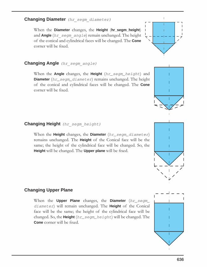
636
Changing Diameter (hr_segm_diameter)
When the Diameter changes, the Height (hr_segm_height) and Angle (hr_segm_angle) remain unchanged. The height of the conical and cylindrical faces will be changed. The Cone corner will be fixed.
Changing Angle (hr_segm_angle)
When the Angle changes, the Height (hr_segm_height) and Diameter (hr_segm_diameter) remains unchanged. The height of the conical and cylindrical faces will be changed. The Cone corner will be fixed.
Changing Height (hr_segm_height)
When the Height changes, the Diameter (hr_segm_diameter) remains unchanged. The Height of the Conical face will be the same; the height of the cylindrical face will be changed. So, the Height will be changed. The Upper plane will be fixed.
Changing Upper Plane
When the Upper Plane changes, the Diameter (hr_segm_diameter) will remain unchanged. The Height of the Conical face will be the same; the height of the cylindrical face will be changed. So, the Height (hr_segm_height) will be changed. The Cone corner will be fixed.
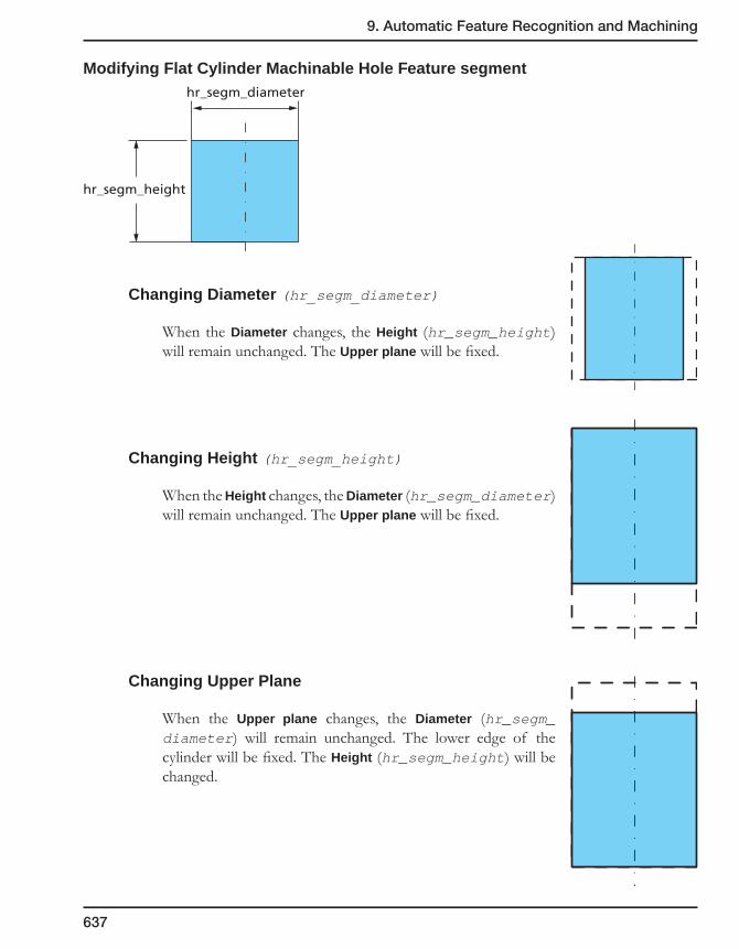
9. Automatic Feature Recognition and Machining
637
Modifying Flat Cylinder Machinable Hole Feature segment
Changing Diameter (hr_segm_diameter)
When the Diameter changes, the Height (hr_segm_height) will remain unchanged. The Upper plane will be fixed.
Changing Height (hr_segm_height)
When the Height changes, the Diameter (hr_segm_diameter) will remain unchanged. The Upper plane will be fixed.
Changing Upper Plane
When the Upper plane changes, the Diameter (hr_segm_diameter) will remain unchanged. The lower edge of the cylinder will be fixed. The Height (hr_segm_height) will be changed.
hr_segm_height
hr_segm_diameter
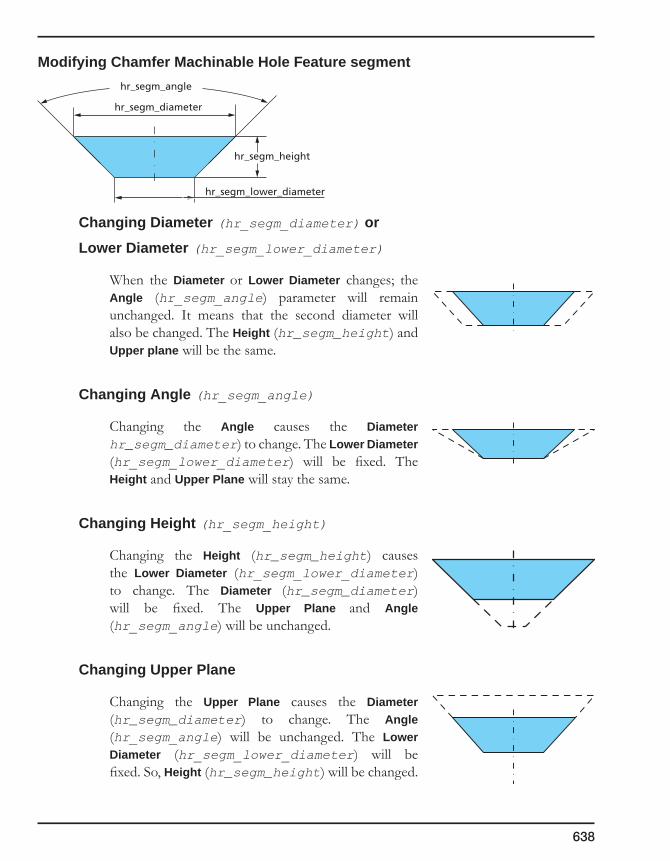
638
Modifying Chamfer Machinable Hole Feature segment
Changing Diameter (hr_segm_diameter) or
Lower Diameter (hr_segm_lower_diameter)
When the Diameter or Lower Diameter changes; the Angle (hr_segm_angle) parameter will remain unchanged. It means that the second diameter will also be changed. The Height (hr_segm_height) and Upper plane will be the same.
Changing Angle (hr_segm_angle)
Changing the Angle causes the Diameter hr_segm_diameter) to change. The Lower Diameter (hr_segm_lower_diameter) will be fixed. The Height and Upper Plane will stay the same.
Changing Height (hr_segm_height)
Changing the Height (hr_segm_height) causes the Lower Diameter (hr_segm_lower_diameter) to change. The Diameter (hr_segm_diameter) will be fixed. The Upper Plane and Angle(hr_segm_angle) will be unchanged.
Changing Upper Plane
Changing the Upper Plane causes the Diameter (hr_segm_diameter) to change. The Angle (hr_segm_angle) will be unchanged. The Lower Diameter (hr_segm_lower_diameter) will be fixed. So, Height (hr_segm_height) will be changed.
hr_segm_height
hr_segm_lower_diameter
hr_segm_diameter
hr_segm_angle

9. Automatic Feature Recognition and Machining
639
Modifying Flat Chamfer Machinable Hole Feature segment
Changing Diameter (hr_segm_diameter) or
Lower Diameter (hr_segm_lower_diameter)
When the Diameter or Lower Diameter changes; the Angle (hr_segm_angle) parameter will remain unchanged. It means that the second diameter will also be changed. The Height (hr_segm_height) and Upper plane will be the same.
Changing Angle (hr_segm_angle)
Changing the Angle causes the Diameter (hr_segm_diameter) to change. The Lower Diameter (hr_segm_lower_diameter) will be fixed. The Height and Upper Plane will stay the same.
Changing Height (hr_segm_height)
Changing the Height (hr_segm_height) causes the Lower Diameter (hr_segm_lower_diameter) to change. The Diameter (hr_segm_diameter) will be fixed. The Upper Plane and Angle (hr_segm_angle) will be unchanged.
Changing Upper Plane
Changing the Upper Plane causes the Diameter (hr_segm_diameter) to change. The Angle (hr_segm_angle) will be unchanged. The Lower Diameter (hr_segm_lower_diameter) will be fixed. So, Height (hr_segm_height) will be changed.
hr_segm_height
hr_segm_lower_diameter
hr_segm_diameter
hr_segm_angle
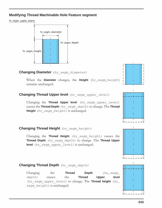
640
Modifying Thread Machinable Hole Feature segment
Changing Diameter (hr_segm_diameter)
When the Diameter changes, the Height (hr_segm_height) remains unchanged.
Changing Thread Upper level (hr_segm_upper_level)
Changing the Thread Upper level (hr_segm_upper_level) causes the Thread Depth (hr_segm_depth) to change. The Thread Height (hr_segm_height) is unchanged.
Changing Thread Height (hr_segm_height)
Changing the Thread Height (hr_segm_height) causes the Thread Depth (hr_segm_depth) to change. The Thread Upper level (hr_segm_upper_level) is unchanged.
Changing Thread Depth (hr_segm_depth)
Changing the Thread Depth (hr_segm_depth) causes the Thread Upper level (hr_segm_upper_level) to change. The Thread height (hr_segm_height) is unchanged.
hr_segm_height
hr_segm_diameter
hr_segm_depth
hr_segm_upper_plane
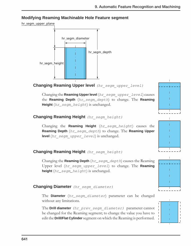
9. Automatic Feature Recognition and Machining
641
Modifying Reaming Machinable Hole Feature segment
Changing Reaming Upper level (hr_segm_upper_level)
Changing the Reaming Upper level (hr_segm_upper_level) causes the Reaming Depth (hr_segm_depth) to change. The Reaming Height (hr_segm_height) is unchanged.
Changing Reaming Height (hr_segm_height)
Changing the Reaming Height (hr_segm_height) causes the Reaming Depth (hr_segm_depth) to change. The Reaming Upper level (hr_segm_upper_level) is unchanged.
Changing Reaming Height (hr_segm_height)
Changing the Reaming Depth (hr_segm_depth) causes the Reaming Upper level (hr_segm_upper_level) to change. The Reaming height (hr_segm_height) is unchanged.
Changing Diameter (hr_segm_diameter)
The Diameter (hr_segm_diameter) parameter can be changed without any limitations.
The Drill diameter (hr_prev_segm_diameter) parameter cannot be changed for the Reaming segment; to change the value you have to edit the Drill/Flat Cylinder segment on which the Reaming is performed.
hr_segm_height
hr_segm_diameter
hr_segm_depth
hr_segm_upper_plane
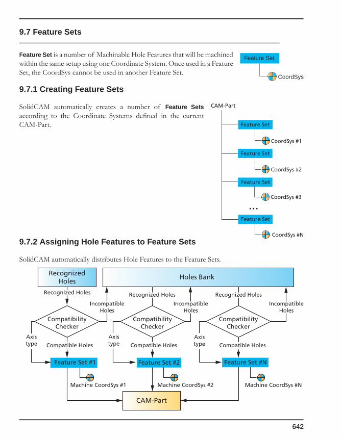
642
9.7 Feature Sets
Feature Set is a number of Machinable Hole Features that will be machined within the same setup using one Coordinate System. Once used in a Feature Set, the CoordSys cannot be used in another Feature Set.
9.7.1 Creating Feature Sets
SolidCAM automatically creates a number of Feature Sets according to the Coordinate Systems defined in the current CAM-Part.
9.7.2 Assigning Hole Features to Feature Sets
SolidCAM automatically distributes Hole Features to the Feature Sets.
Feature Set
CoordSys #1
Feature Set
CoordSys #2
Feature Set
CoordSys #3
Feature Set
CoordSys #N
...
CAM-Part
Feature Set
CoordSys
RecognizedHoles
Holes Bank
CAM-Part
CompatibilityChecker
CompatibilityChecker
CompatibilityChecker
Feature Set #1
Machine CoordSys #1
Feature Set #2
Machine CoordSys #2
Feature Set #N
Machine CoordSys #N
Recognized Holes Recognized Holes Recognized Holes
IncompatibleHoles
Compatible Holes Compatible Holes Compatible Holes
IncompatibleHoles
IncompatibleHoles
Axistype
Axistype
Axistype

9. Automatic Feature Recognition and Machining
643
SolidCAM checks the compatibility of the Machinable Hole Features with the Feature Sets and assigns Holes to the Feature Sets. The compatibility checker examines each Machinable Hole Feature according to the CoordSys (owned by the specific Feature Set) and the Axis type of the Feature Set.
Axis type enables you to limit the number of the axes used for the machining of the Machinable Hole Features in Feature Set; the Axis number can be the same or smaller than Axis number of the CAM-Part. The Machinable Hole Features included in the Feature Set will be machined according to this Axis number, not considering the Axis number of the CAM-Part.
Each Machinable Hole Feature can be assigned to a specific Feature Set if one of the following conditions is kept:
• The direction of the Machinable Hole Feature is parallel to the Z-axis of the Coordinate System;
• It is possible to define a CoordSys position (according to the Axis Type) under the Machine Coordinate System with the Z-axis parallel to the direction of the Machinable Hole Feature.
The order of the assignment depends on the Machine CoordSys Number; the Feature Set with the smaller Machine CoordSys number will be filled with Machinable Hole Features first. Thus, if the Machinable Hole Feature is compatible to a number of Feature Sets, the Machinable Hole Feature will be assigned to the Feature Set using the Machine CoordSys with the lowest number.
The Machinable Hole Features that were not assigned are stored in the bank of the Recognized Hole Features.
9.7.3 Automatic CoordSys Positions definition
SolidCAM automatically defines CoordSys Positions related to the Machine CoordSys suitable to machine Machinable Hole Features of a specific Feature Set. The CoordSys Position is created according to the following data:
• The Machine CoordSys used in the Feature Set;
• The Axis type of the Feature Set;
• The Direction of the Machinable Hole Feature.
Feature Set
Axis type Machine CoordSys Direction
Hole Feature
CoordSys Position
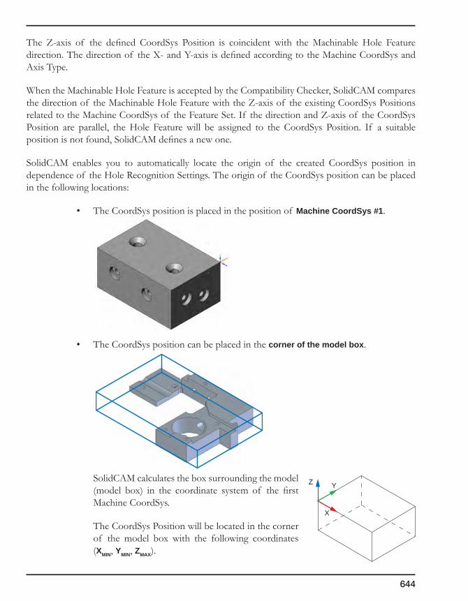
644
The Z-axis of the defined CoordSys Position is coincident with the Machinable Hole Feature direction. The direction of the X- and Y-axis is defined according to the Machine CoordSys and Axis Type.
When the Machinable Hole Feature is accepted by the Compatibility Checker, SolidCAM compares the direction of the Machinable Hole Feature with the Z-axis of the existing CoordSys Positions related to the Machine CoordSys of the Feature Set. If the direction and Z-axis of the CoordSys Position are parallel, the Hole Feature will be assigned to the CoordSys Position. If a suitable position is not found, SolidCAM defines a new one.
SolidCAM enables you to automatically locate the origin of the created CoordSys position in dependence of the Hole Recognition Settings. The origin of the CoordSys position can be placed in the following locations:
• The CoordSys position is placed in the position of Machine CoordSys #1.
• The CoordSys position can be placed in the corner of the model box.
SolidCAM calculates the box surrounding the model (model box) in the coordinate system of the first Machine CoordSys.
The CoordSys Position will be located in the corner of the model box with the following coordinates (XMIN, YMIN, ZMAX).
YZ
X
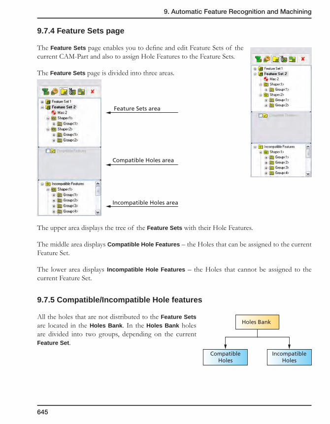
9. Automatic Feature Recognition and Machining
645
9.7.4 Feature Sets page
The Feature Sets page enables you to define and edit Feature Sets of the current CAM-Part and also to assign Hole Features to the Feature Sets.
The Feature Sets page is divided into three areas.
The upper area displays the tree of the Feature Sets with their Hole Features.
The middle area displays Compatible Hole Features – the Holes that can be assigned to the current Feature Set.
The lower area displays Incompatible Hole Features – the Holes that cannot be assigned to the current Feature Set.
9.7.5 Compatible/Incompatible Hole features
All the holes that are not distributed to the Feature Sets are located in the Holes Bank. In the Holes Bank holes are divided into two groups, depending on the current Feature Set.
Feature Sets area
Compatible Holes area
Incompatible Holes area
Holes Bank
CompatibleHoles
IncompatibleHoles
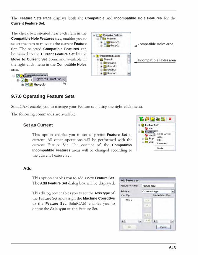
646
The Feature Sets Page displays both the Compatible and Incompatible Hole Features for the Current Feature Set.
The check box situated near each item in the Compatible Hole Features tree, enables you to select the item to move to the current Feature Set. The selected Compatible Features can be moved to the Current Feature Set by the Move to Current Set command available in the right-click menu in the Compatible Holes area.
9.7.6 Operating Feature Sets
SolidCAM enables you to manage your Feature sets using the right-click menu.
The following commands are available:
Set as Current
This option enables you to set a specific Feature Set as current. All other operations will be performed with the current Feature Set. The content of the Compatible/Incompatible Features areas will be changed according to the current Feature Set.
Add
This option enables you to add a new Feature Set. The Add Feature Set dialog box will be displayed.
This dialog box enables you to set the Axis type of the Feature Set and assign the Machine CoordSys to the Feature Set. SolidCAM enables you to define the Axis type of the Feature Set.
Compatible Holes area
Incompatible Holes area

9. Automatic Feature Recognition and Machining
647
Edit
This option displays the Edit Feature Set dialog box.
This dialog box enables you to edit the name and Axis type of the Feature Set and change the Machine CoordSys assigned to the Feature Set.
Remove All
This option enables you to remove all Machinable Hole Features from the Feature Set. All the Machinable Features will be moved to the Holes bank.
Delete
This option enables you to delete the Feature Set. All the Machinable Features will be moved to the Holes bank.
9.7.7 Defining the CoordSys Position origin location for the Feature Set
SolidCAM enables you to define the default location of the CoordSys Position origin with the right-click menu on the Machine CoordSys of the specified Feature Set.
The Place CoordSys origin at dialog box is displayed.
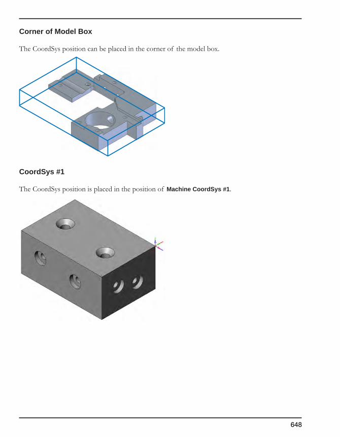
648
Corner of Model Box
The CoordSys position can be placed in the corner of the model box.
CoordSys #1
The CoordSys position is placed in the position of Machine CoordSys #1.

9. Automatic Feature Recognition and Machining
649
9.8 Technology
For the each segment of the Machinable Hole Feature, SolidCAM chooses:
• A suitable technological solution from the Technology Database (TDB) (see topic 9.10).
• A tool from the Part Tool Table (see topic 3.6) or defines a new tool.
9.8.1 Choosing a Technological Solution
SolidCAM stores all Technological Solutions in the Technology Database. All the Technological solutions are classified according to the type of Machinable Hole Feature segments.
Part Tool Table
Technology Database
TechnologicalSolution
MachinableHole Feature
Segment
Operations
Technological Solutions
Technology Database
Drill MachinableFeature Segment
Flat Cylinder MachinableFeature Segment
Flat Chamfer MachinableFeature Segment
Chamfer MachinableFeature Segment
Technological Solutions
Technological Solutions
Technological Solutions
Thread MachinableFeature Segment
Technological Solutions
Reaming MachinableFeature Segment
Technological Solutions

650
For each type of Machinable Hole Feature segment, there is a number of technological solutions (each technological solution can belong to only one type of Machinable Hole Feature segment).
A Technological solution can be either a user-defined Machining Process or a built-in Algorithm.
• The user-defined Machining process contains Operation templates with parametric technology data and parametric data of the tools. It can be defined and edited by the user.
• A built-in Algorithm is hard-coded in SolidCAM; it generates a number of Machining Processes. Parameters of the algorithm can be edited.
Technological solutions use the dimensions of the Machinable Hole Feature Segments.
SolidCAM automatically chooses the suitable Technological solutions for the machining of the specified Machinable Hole Feature segment from the TDB. The choice of the Technological solution is defined by the set of conditions. A Condition is a logical expression; its result can be either true or false. When the condition is true, the current technological solution can be used to machine the Machinable Hole Feature segment. SolidCAM checks the conditions of the technological solutions in sequence; the first solution with a true condition will be chosen.
9.8.2 Choosing the tool
When a Technological Solution is chosen from the TDB, SolidCAM chooses the suitable Tool from the Part Tool Table. The method of choosing the tools depends on the type of the operation where the tool is used. SolidCAM differentiates between the following types of operations:
• DrillingOperation
• MillingOperation
• CenterDrillingOperation
• ChamferDrillingOperation
• Center-ChamferDrillingOperation
• ThreadMillingOperation
• ReamingOperation
Technological Solutions
Technological Solution
Algorithm
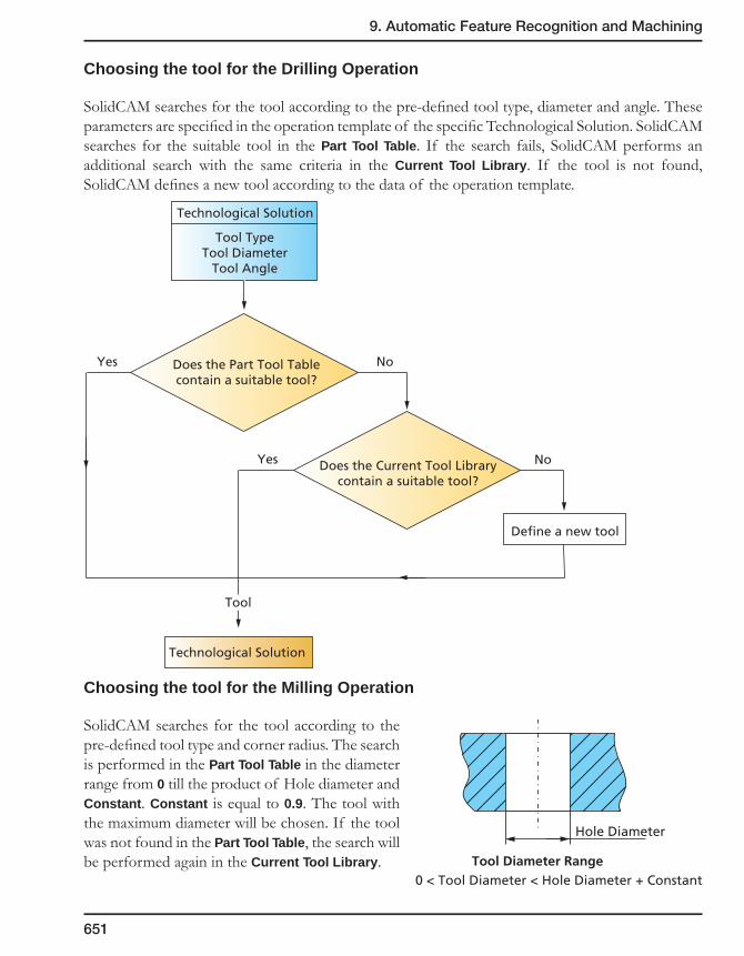
9. Automatic Feature Recognition and Machining
651
Choosing the tool for the Drilling Operation
SolidCAM searches for the tool according to the pre-defined tool type, diameter and angle. These parameters are specified in the operation template of the specific Technological Solution. SolidCAM searches for the suitable tool in the Part Tool Table. If the search fails, SolidCAM performs an additional search with the same criteria in the Current Tool Library. If the tool is not found, SolidCAM defines a new tool according to the data of the operation template.
Choosing the tool for the Milling Operation
SolidCAM searches for the tool according to the pre-defined tool type and corner radius. The search is performed in the Part Tool Table in the diameter range from 0 till the product of Hole diameter and Constant. Constant is equal to 0.9. The tool with the maximum diameter will be chosen. If the tool was not found in the Part Tool Table, the search will be performed again in the Current Tool Library.
Hole Diameter
Tool Diameter Range0 < Tool Diameter < Hole Diameter + Constant
Does the Part Tool Tablecontain a suitable tool?
Does the Current Tool Librarycontain a suitable tool?
Technological Solution
Tool TypeTool Diameter
Tool Angle
Define a new tool
Technological Solution
Tool
Yes
Yes
No
No
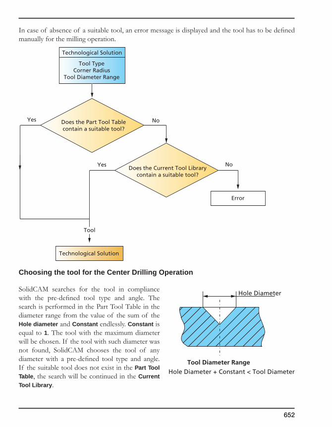
652
In case of absence of a suitable tool, an error message is displayed and the tool has to be defined manually for the milling operation.
Choosing the tool for the Center Drilling Operation
SolidCAM searches for the tool in compliance with the pre-defined tool type and angle. The search is performed in the Part Tool Table in the diameter range from the value of the sum of the Hole diameter and Constant endlessly. Constant is equal to 1. The tool with the maximum diameter will be chosen. If the tool with such diameter was not found, SolidCAM chooses the tool of any diameter with a pre-defined tool type and angle. If the suitable tool does not exist in the Part Tool Table, the search will be continued in the Current Tool Library.
Does the Part Tool Tablecontain a suitable tool?
Does the Current Tool Librarycontain a suitable tool?
Technological Solution
Tool TypeCorner Radius
Tool Diameter Range
Error
Technological Solution
Tool
Yes
Yes
No
No
Hole Diameter
Tool Diameter Range Hole Diameter + Constant < Tool Diameter
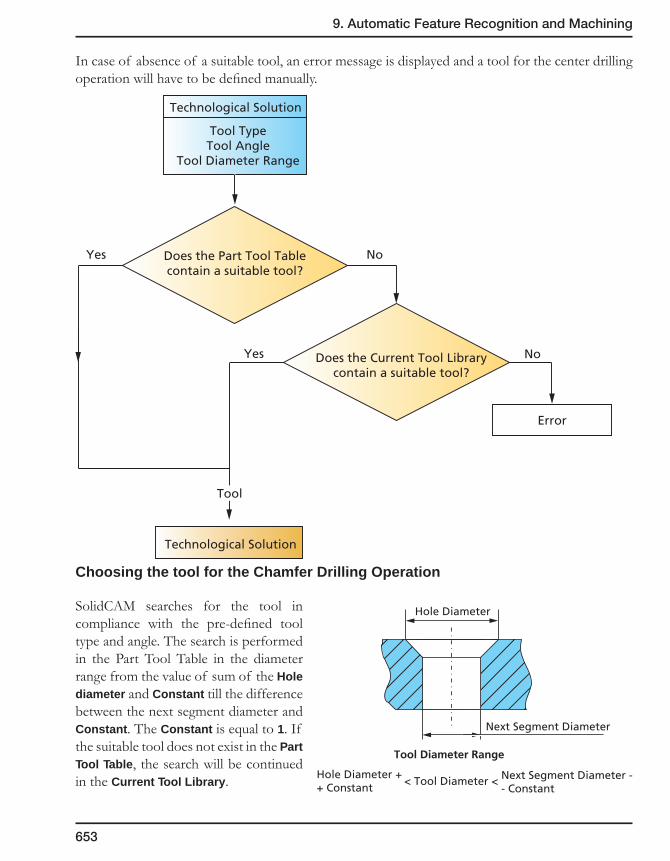
9. Automatic Feature Recognition and Machining
653
In case of absence of a suitable tool, an error message is displayed and a tool for the center drilling operation will have to be defined manually.
Choosing the tool for the Chamfer Drilling Operation
SolidCAM searches for the tool in compliance with the pre-defined tool type and angle. The search is performed in the Part Tool Table in the diameter range from the value of sum of the Hole diameter and Constant till the difference between the next segment diameter and Constant. The Constant is equal to 1. If the suitable tool does not exist in the Part Tool Table, the search will be continued in the Current Tool Library.
Next Segment Diameter
Tool Diameter Range
< Tool Diameter < Next Segment Diameter -- Constant
Hole Diameter ++ Constant
Hole Diameter
Does the Part Tool Tablecontain a suitable tool?
Does the Current Tool Librarycontain a suitable tool?
Technological Solution
Tool TypeTool Angle
Tool Diameter Range
Error
Technological Solution
Tool
Yes
Yes
No
No

654
In case of absence of a suitable tool, SolidCAM defines a new tool with the pre-defined tool type, angle and minimum possible diameter (Hole diameter + Constant).
Choosing the tool for the Center Chamfer Drilling Operation
SolidCAM searches for the tool in compliance with the pre-defined tool type and angle. The search is performed in the Part Tool Table in the diameter range from the value of sum of hole diameter and Constant endlessly. The Constant is equal to 1. The tool with the maximum diameter will be chosen. If the tool with such diameter is not found, SolidCAM chooses the tool of any diameter with a pre-defined tool type and angle. If the suitable tool does not exist in the Part Tool Table, the search will be continued in the Current Tool Library.
Does the Part Tool Tablecontain a suitable tool?
Does the Current Tool Librarycontain a suitable tool?
Technological Solution
Tool TypeTool Angle
Tool Diameter Range
Define a new tool:tool diameter = hole diameter + constant
Technological Solution
Tool
Yes
Yes
No
No
Tool Diameter Range
< Tool DiameterHole Diameter ++ Constant
Hole Diameter
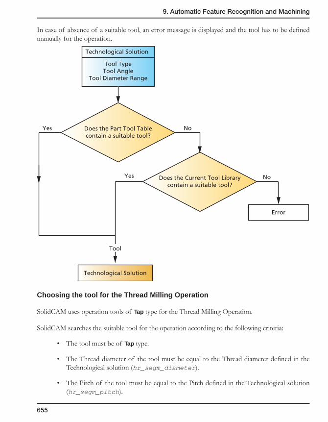
9. Automatic Feature Recognition and Machining
655
In case of absence of a suitable tool, an error message is displayed and the tool has to be defined manually for the operation.
Choosing the tool for the Thread Milling Operation
SolidCAM uses operation tools of Tap type for the Thread Milling Operation.
SolidCAM searches the suitable tool for the operation according to the following criteria:
• The tool must be of Tap type.
• The Thread diameter of the tool must be equal to the Thread diameter defined in the Technological solution (hr_segm_diameter).
• The Pitch of the tool must be equal to the Pitch defined in the Technological solution (hr_segm_pitch).
Does the Part Tool Tablecontain a suitable tool?
Does the Current Tool Librarycontain a suitable tool?
Technological Solution
Tool TypeTool Angle
Tool Diameter Range
Error
Technological Solution
Tool
Yes
Yes
No
No

656
These parameters are specified in the Operation template of the specific Technological Solution. SolidCAM searches for the suitable tool in the Part Tool Table. If the search fails, SolidCAM performs an additional search with the same criteria in the Current Tool Library. If the tool is not found, SolidCAM defines a new tool according to the data of the Operation Template.
Choosing the tool for the Reaming Operation
SolidCAM uses tools of Reamer tool type for the Reaming Operation.
SolidCAM searches the suitable tool for the operation according to the following criteria:
• The tool must be of Reamer tool type.
• The Reamer Diameter of the tool must be equal to the Reaming diameter defined in the Technological solution (hr_segm_diameter).
Does the Part Tool Tablecontain a suitable tool?
Does the Current Tool Librarycontain a suitable tool?
Technological Solution
Tool TypeThread Diameter
Pitch
Define a new tool
Technological Solution
Tool
Yes
Yes
No
No
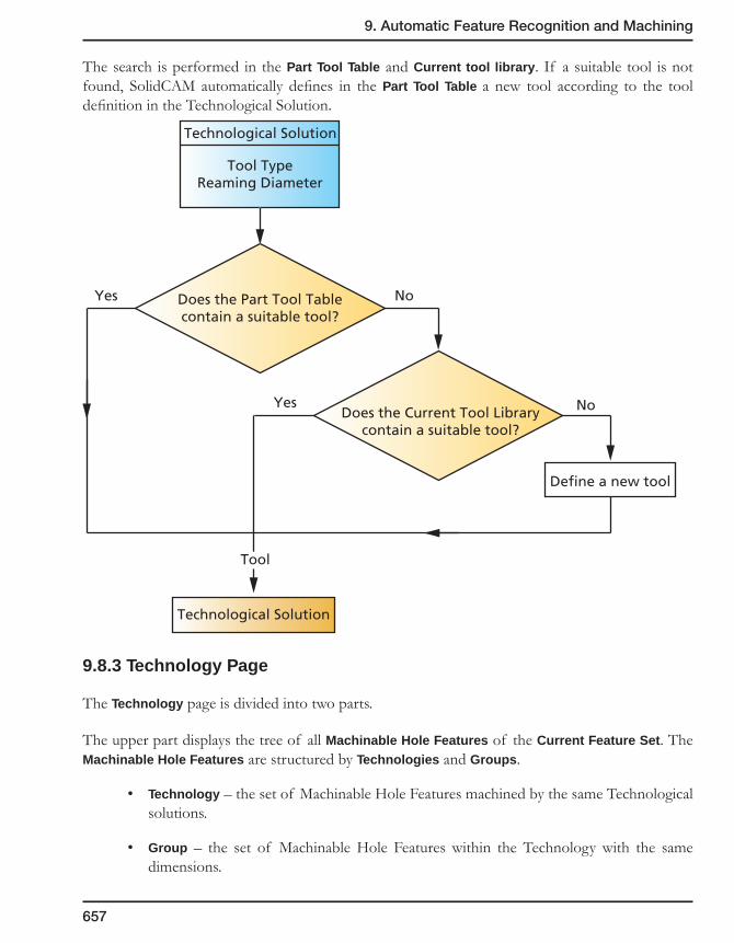
9. Automatic Feature Recognition and Machining
657
The search is performed in the Part Tool Table and Current tool library. If a suitable tool is not found, SolidCAM automatically defines in the Part Tool Table a new tool according to the tool definition in the Technological Solution.
9.8.3 Technology Page
The Technology page is divided into two parts.
The upper part displays the tree of all Machinable Hole Features of the Current Feature Set. The Machinable Hole Features are structured by Technologies and Groups.
• Technology – the set of Machinable Hole Features machined by the same Technological solutions.
• Group – the set of Machinable Hole Features within the Technology with the same dimensions.
Does the Part Tool Tablecontain a suitable tool?
Does the Current Tool Librarycontain a suitable tool?
Technological Solution
Tool TypeReaming Diameter
Define a new tool
Technological Solution
Tool
Yes
Yes
No
No
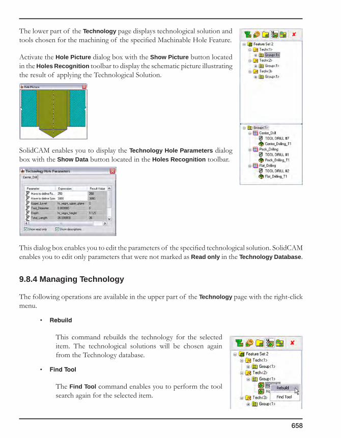
658
The lower part of the Technology page displays technological solution and tools chosen for the machining of the specified Machinable Hole Feature.
Activate the Hole Picture dialog box with the Show Picture button located in the Holes Recognition toolbar to display the schematic picture illustrating the result of applying the Technological Solution.
SolidCAM enables you to display the Technology Hole Parameters dialog box with the Show Data button located in the Holes Recognition toolbar.
This dialog box enables you to edit the parameters of the specified technological solution. SolidCAM enables you to edit only parameters that were not marked as Read only in the Technology Database.
9.8.4 Managing Technology
The following operations are available in the upper part of the Technology page with the right-click menu.
• Rebuild
This command rebuilds the technology for the selected item. The technological solutions will be chosen again from the Technology database.
• FindTool
The Find Tool command enables you to perform the tool search again for the selected item.

9. Automatic Feature Recognition and Machining
659
This command is useful in the following cases:
• When the suitable tool was not found in the Part Tool Table and was not defined by SolidCAM.
• The Part Tool Table was updated.
Managing Technological solutions
The lower part of the Technology Page displays the set of Technological solutions necessary to the machining of the selected Machinable Hole Feature.
• Change
This option enables you to change the Technological Solution. The Machining process list dialog will be displayed; this dialog enables you to choose the necessary solution from the list of available Solutions for this type of Machinable Hole Feature segment.
• Findtool
This command enables you to automatically find the suitable tool from the Part Tool Table for the selected Technological Solution.
This command is useful in the following cases:
• When the suitable tool was not found in the Part Tool Table and was not defined by SolidCAM.
• The Part Tool Table was updated.
SolidCAM enables you to change the tool for the Technological solution with the Change Tool option. The option is available with the right-click menu on the Tool item.
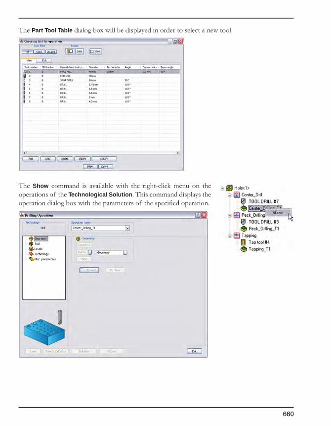
660
The Part Tool Table dialog box will be displayed in order to select a new tool.
The Show command is available with the right-click menu on the operations of the Technological Solution. This command displays the operation dialog box with the parameters of the specified operation.

9. Automatic Feature Recognition and Machining
661
9.9 Generating Operations
When the Technology is defined, SolidCAM displays the generated operations in the Operations page. These operations are also available in SolidCAM Manager.
The Edit command is available for the Operations in the right-click menu.
This command enables you to display the operation dialog box.

662
9.10 Technology Database
The SolidCAM Technology Database (TDB) stores all the Technological solutions available for the machining of the Machinable Hole Feature segments. The Technological solutions in TDB are classified according to types of Machinable Features Hole Feature segments. For each type of Machinable Hole Feature segment, there is a number of connected technological solutions (each technological solution can belong to only one type of Machinable Hole Feature segment).
Technological Solutions
Technology Database
Drill MachinableFeature Segment
Flat Cylinder MachinableFeature Segment
Flat Chamfer MachinableFeature Segment
Chamfer MachinableFeature Segment
Technological Solutions
Technological Solutions
Technological Solutions
Thread MachinableFeature Segment
Technological Solutions
Reaming MachinableFeature Segment
Technological Solutions

9. Automatic Feature Recognition and Machining
663
9.10.1 Global and Local Technology databases
When SolidCAM is installed, the Global Technology Database is also installed in the system folder of SolidCAM. SolidCAM enables you to customize the Global TDB by adding and editing Technological solutions.
When SolidCAM starts the AFRM process, the Global TDB will be copied into the CAM-Part folder. This copy is called the Local TDB. During the AFRM process, SolidCAM receives data only from the Local TDB. The Local TDB can be modified by the user for specific tasks in the context of the specific CAM-Part.
The Global TDB can be replaced with the Local TDB.
SolidCAM enables you to load the Global TDB with the Technology Database command from the SolidCAM menu.
The Technology Database Manager dialog box is displayed containing the Global TDB.
The Global Technology Database is unavailable when the Holes Recognition process is working. In this case only the Local TDB can be edited.
The Local Technology Database can be loaded only when the Holes Recognition process is working. The Local TDB can be loaded by clicking on the related icon from the Holes Recognition toolbar.
The Technology Database Manager dialog box is displayed containing the Local TDB.
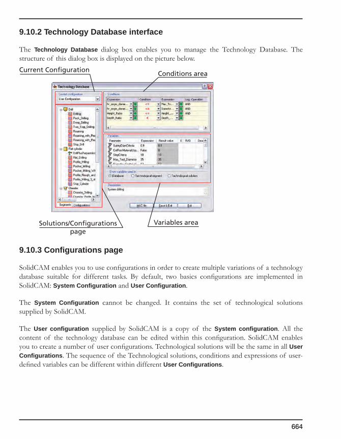
664
9.10.2 Technology Database interface
The Technology Database dialog box enables you to manage the Technology Database. The structure of this dialog box is displayed on the picture below.
9.10.3 Configurations page
SolidCAM enables you to use configurations in order to create multiple variations of a technology database suitable for different tasks. By default, two basics configurations are implemented in SolidCAM: System Configuration and User Configuration.
The System Configuration cannot be changed. It contains the set of technological solutions supplied by SolidCAM.
The User configuration supplied by SolidCAM is a copy of the System configuration. All the content of the technology database can be edited within this configuration. SolidCAM enables you to create a number of user configurations. Technological solutions will be the same in all User Configurations. The sequence of the Technological solutions, conditions and expressions of user-defined variables can be different within different User Configurations.
Current Configuration
Solutions/Configurationspage
Conditions area
Variables area

9. Automatic Feature Recognition and Machining
665
The Configurations page of the TDB Manager enables you to manage configurations of TDB, either Global or Local.
SolidCAM enables you to perform the following operations with the right-click menu.
Set as Current
This option enables you to make the specified configuration current. All the further operation will be performed for the Current Configuration.
Rename
This option enables you to change the name of the specified User Configuration.
The System Configuration cannot be renamed.
Copy
This option enables you to create a copy of the specified User Configuration.
The System Configuration cannot be copied.
Delete
This option enables you to remove the specified User Configuration.
The System Configuration, Current Configuration and last User Configuration cannot be deleted.
9.10.4 Current Configuration
The Current Configuration combo box displays the name of the current configuration and enables you to switch quickly between configurations in TDB.
When the Configurations page is displayed, the Current Configuration combo box is disabled; it only shows the name of the current configuration.
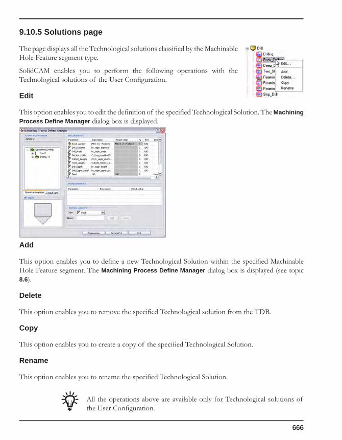
666
9.10.5 Solutions page
The page displays all the Technological solutions classified by the Machinable Hole Feature segment type.
SolidCAM enables you to perform the following operations with the Technological solutions of the User Configuration.
Edit
This option enables you to edit the definition of the specified Technological Solution. The Machining Process Define Manager dialog box is displayed.
Add
This option enables you to define a new Technological Solution within the specified Machinable Hole Feature segment. The Machining Process Define Manager dialog box is displayed (see topic 8.6).
Delete
This option enables you to remove the specified Technological solution from the TDB.
Copy
This option enables you to create a copy of the specified Technological Solution.
Rename
This option enables you to rename the specified Technological Solution.
All the operations above are available only for Technological solutions of the User Configuration.

9. Automatic Feature Recognition and Machining
667
For the Technological solutions of the System Configuration, the following options are available:
View
This option enables you to display the specified Technological Solution in Machining Process View Manager. The displayed Solution cannot be edited.
Copy To User Configurations
This option enables you to copy the specified Technological Solution to the User Configurations. Since all the User Configurations use the same Technological solutions, the copied Technological solution can be used in all User Configurations.
9.10.6 Conditions
SolidCAM enables you to define the following set of conditions. If these conditions are true, the technological solution is chosen.
A Condition is a complex logical expression; its result can be either true or false. When the condition is true, the current Technological solution can be used. SolidCAM checks the conditions of the Technological solutions in a defined sequence; the first solution with a true condition will be chosen.
A Condition consists of condition lines combined by the logical operators AND and OR. A Condition line is a comparison of two expressions. The following comparison operators are acceptable in condition lines:
• >(greaterthan);
• <(smallerthan);
• =(equal);
• <=(smallerthanorequal);
• >=(greaterthanorequal).
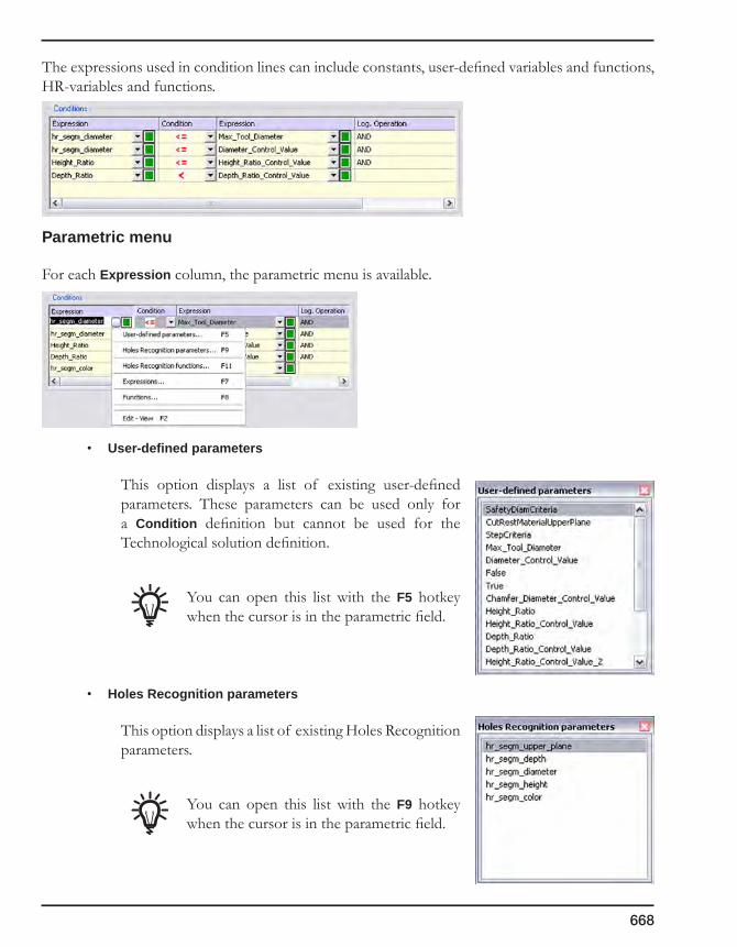
668
The expressions used in condition lines can include constants, user-defined variables and functions, HR-variables and functions.
Parametric menu
For each Expression column, the parametric menu is available.
• User-defined parameters
This option displays a list of existing user-defined parameters. These parameters can be used only for a Condition definition but cannot be used for the Technological solution definition.
You can open this list with the F5 hotkey when the cursor is in the parametric field.
• Holes Recognition parameters
This option displays a list of existing Holes Recognition parameters.
You can open this list with the F9 hotkey when the cursor is in the parametric field.
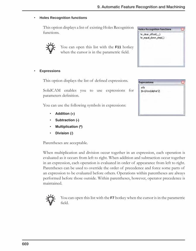
9. Automatic Feature Recognition and Machining
669
• Holes Recognition functions
This option displays a list of existing Holes Recognition functions.
You can open this list with the F11 hotkey when the cursor is in the parametric field.
• Expressions
This option displays the list of defined expressions.
SolidCAM enables you to use expressions for parameters definition.
You can use the following symbols in expressions:
• Addition(+)
• Subtraction(-)
• Multiplication(*)
• Division(/)
Parentheses are acceptable.
When multiplication and division occur together in an expression, each operation is evaluated as it occurs from left to right. When addition and subtraction occur together in an expression, each operation is evaluated in order of appearance from left to right. Parentheses can be used to override the order of precedence and force some parts of an expression to be evaluated before others. Operations within parentheses are always performed before those outside. Within parentheses, however, operator precedence is maintained.
You can open this list with the F7 hotkey when the cursor is in the parametric field.

670
• Functions
This option displays a list of existing Standard Functions.
You can open this list with the F8 hotkey when the cursor is in the parametric field.
• Edit-View
This option displays the parameter edit dialog box.
Here you can see and edit the full parameter name or expression string.
You can open this list with the F2 hotkey when the cursor is in the parametric field.
9.10.7 Variables
The Variables area displays the list of variables and their expressions used in the Conditions area.
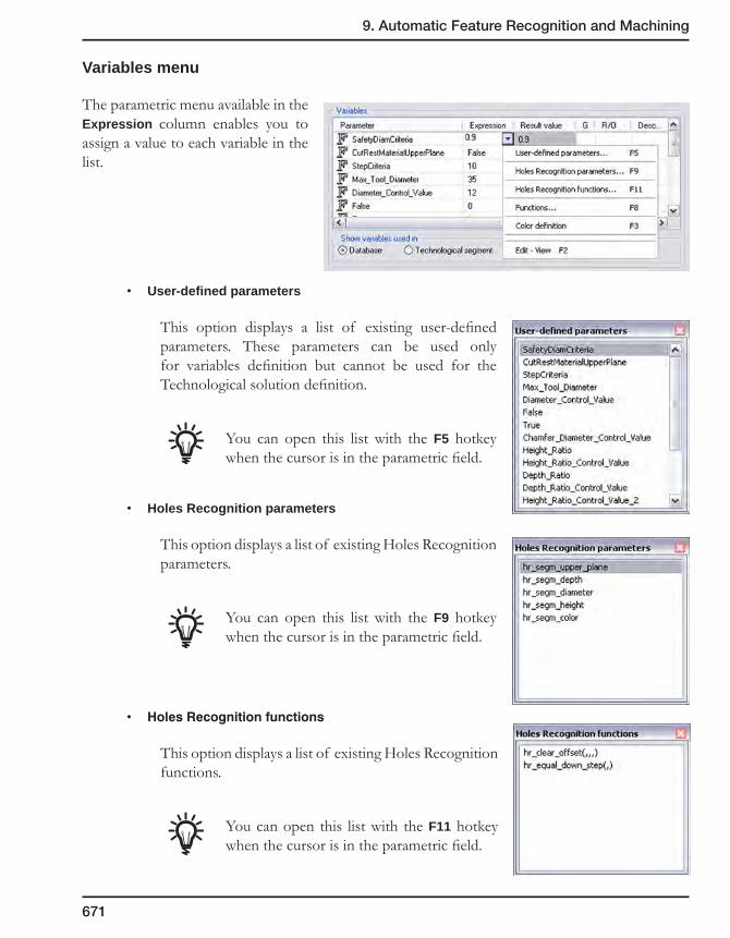
9. Automatic Feature Recognition and Machining
671
Variables menu
The parametric menu available in the Expression column enables you to assign a value to each variable in the list.
• User-defined parameters
This option displays a list of existing user-defined parameters. These parameters can be used only for variables definition but cannot be used for the Technological solution definition.
You can open this list with the F5 hotkey when the cursor is in the parametric field.
• Holes Recognition parameters
This option displays a list of existing Holes Recognition parameters.
You can open this list with the F9 hotkey when the cursor is in the parametric field.
• HolesRecognitionfunctions
This option displays a list of existing Holes Recognition functions.
You can open this list with the F11 hotkey when the cursor is in the parametric field.

672
• Colordefinition
This option enables you to assign the color value to the variable using the Select Color dialog box.
The colored button enables you to choose the color from the Color dialog box.
The Pick face button enables you to define the color by picking the model face. The color of the picked face will be captured and displayed in the dialog box. The Float value of the color and its RGB values are displayed in the corresponding edit boxes. When the dialog box is confirmed with the OK button, the Float color value is assigned to the variable.
You can open this list with the F3 hotkey when the cursor is in the parametric field.
• Functions
This option displays a list of existing Standard Functions.
You can open this list with the F8 hotkey when the cursor is in the parametric field.
• Edit-View
This option displays the parameter edit dialog box in which you can see and edit the full parameter name or expression string.
You can open this list with the F2 hotkey when the cursor is in the parametric field.
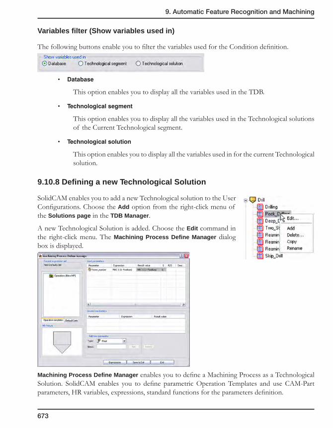
9. Automatic Feature Recognition and Machining
673
Variables filter (Show variables used in)
The following buttons enable you to filter the variables used for the Condition definition.
• Database
This option enables you to display all the variables used in the TDB.
• Technologicalsegment
This option enables you to display all the variables used in the Technological solutions of the Current Technological segment.
• Technologicalsolution
This option enables you to display all the variables used in for the current Technological solution.
9.10.8 Defining a new Technological Solution
SolidCAM enables you to add a new Technological solution to the User Configurations. Choose the Add option from the right-click menu of the Solutions page in the TDB Manager.
A new Technological Solution is added. Choose the Edit command in the right-click menu. The Machining Process Define Manager dialog box is displayed.
Machining Process Define Manager enables you to define a Machining Process as a Technological Solution. SolidCAM enables you to define parametric Operation Templates and use CAM-Part parameters, HR variables, expressions, standard functions for the parameters definition.
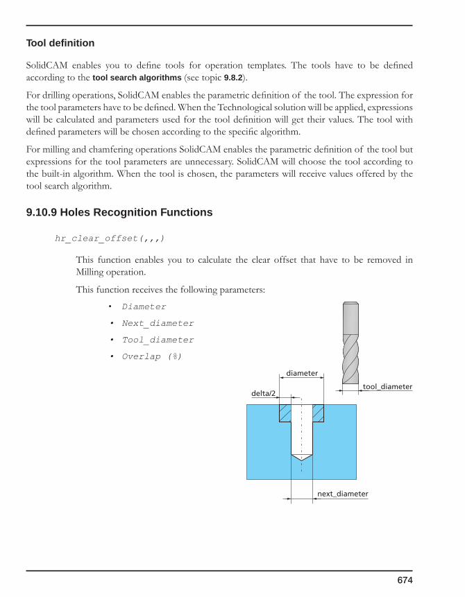
674
Tool definition
SolidCAM enables you to define tools for operation templates. The tools have to be defined according to the tool search algorithms (see topic 9.8.2).
For drilling operations, SolidCAM enables the parametric definition of the tool. The expression for the tool parameters have to be defined. When the Technological solution will be applied, expressions will be calculated and parameters used for the tool definition will get their values. The tool with defined parameters will be chosen according to the specific algorithm.
For milling and chamfering operations SolidCAM enables the parametric definition of the tool but expressions for the tool parameters are unnecessary. SolidCAM will choose the tool according to the built-in algorithm. When the tool is chosen, the parameters will receive values offered by the tool search algorithm.
9.10.9 Holes Recognition Functions
hr_clear_offset(,,,)
This function enables you to calculate the clear offset that have to be removed in Milling operation.
This function receives the following parameters:
• Diameter
• Next_diameter
• Tool_diameter
• Overlap (%)
delta/2
next_diameter
tool_diameter
diameter
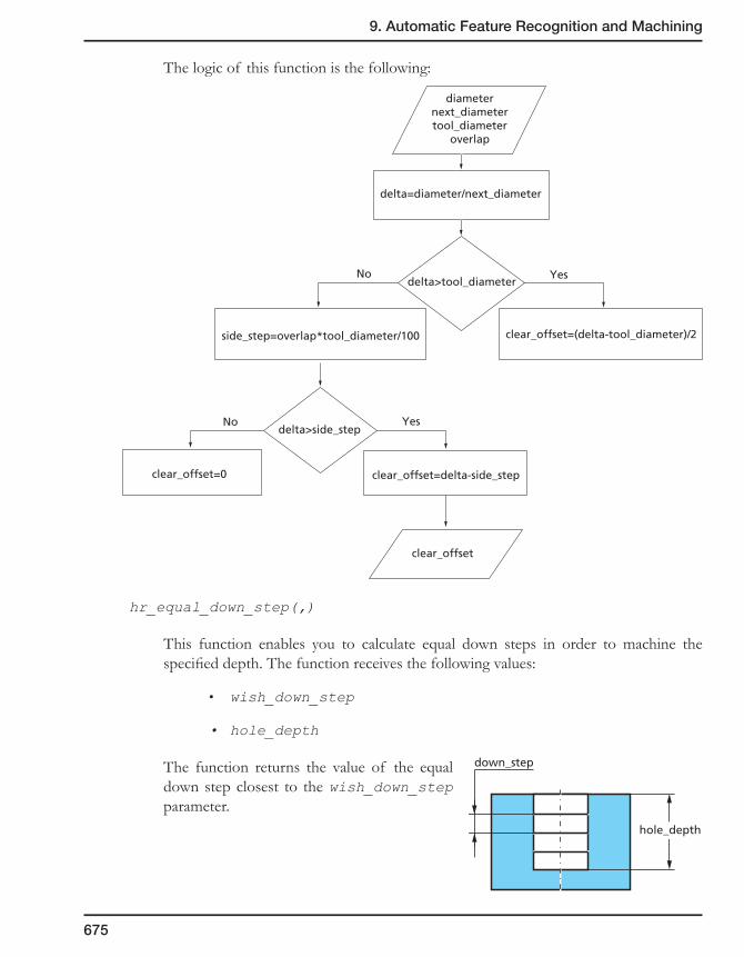
9. Automatic Feature Recognition and Machining
675
The logic of this function is the following:
hr_equal_down_step(,)
This function enables you to calculate equal down steps in order to machine the specified depth. The function receives the following values:
• wish_down_step
• hole_depth
The function returns the value of the equal down step closest to the wish_down_step parameter.
diameternext_diametertool_diameter
overlap
delta=diameter/next_diameter
side_step=overlap*tool_diameter/100 clear_offset=(delta-tool_diameter)/2
clear_offset=0 clear_offset=delta-side_step
clear_offset
delta>tool_diameter
delta>side_step
No Yes
No Yes
down_step
hole_depth

676
9.11 Holes Recognition Settings
SolidCAM enables you to define the System and Part settings of the Holes Recognition with the Holes Recognition settings dialog box.
The Holes Recognition settings dialog box structure has two tabs:
• System settings are stored in the registry and affect all CAM-Parts.
• Part settings apply only to the current CAM-Part.
9.11.1 System settings
The system settings are stored in the registry and affect all the CAM-Parts.
Topology
General
This page enables you to define the location of the Coordinate System.
Place CoordSys at:
This option enables you to set the default location for the CoordSys position created by the AFRM at the stage of the Feature Sets definition.
• CornerofModelBox
The CoordSys position is automatically placed at the corner of the box surrounding the model.
• CoordSys#1
The CoordSys position is automatically placed at the position of Machine CoordSys #1.

9. Automatic Feature Recognition and Machining
677
Connection
This page enables you to define parameters of the Hole Features connection.
Connection Holes
This option enables you to turn on/off the connection of the Hole Features.
• Axis Tolerance
This parameter enables you to define the tolerance of the concentricity for the Hole Features that can be connected.
• UseMax Distance between Holes
When this option is turned on, SolidCAM enables you to specify the maximal distance between hole features that can be connected.
If the distance between the holes exceeds the specified value, holes will not be connected.
Thread
This page enables you to define the way how the threads are recognized.
• ByusingHoleWizardinformation
The information from HoleWizard to determine threads and their parameters. When the By Cosmetic thread check box is selected, SolidCAM recognizes holes where thread is created by HoleWizard as a Cosmetic thread feature. When the By Hole specification and Hole shape check box is selected, SolidCAM recognizes holes using the information from the HoleWizard and analyzing the hole shape.
• ByHoleshape
SolidCAM analyzes the hole shape in order to recognize threads in holes.
Distance

678
Technology
General
• Add Center Drill
This option enables SolidCAM to automatically perform the center drilling. The center drilling will be inserted before the machining of the first Machinable Hole Feature segment that will be machined with the drilling technology.
• Calculate operations inside Holes Recognition
This option enables you to postpone the calculation of the operations during insert them from the AFRM. Not calculated operations can be calculated later together with other CAM-Part operations.
When this check box is selected (default), SolidCAM calculates the operations inserted by AFRM.
Colors
This page enables you to define the colors that will be used in the HR Manager for the items changed or inserted by the user.
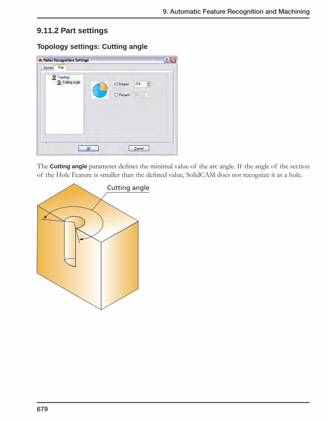
9. Automatic Feature Recognition and Machining
679
9.11.2 Part settings
Topology settings: Cutting angle
The Cutting angle parameter defines the minimal value of the arc angle. If the angle of the section of the Hole Feature is smaller than the defined value, SolidCAM does not recognize it as a hole.
Cutting angle

680
Simulation 10You can use the simulation to check and view the generated tool path after you have defined and calculated your machining operations.
If you have made mistakes defining the operations or used unsuitable milling strategies, the simulation can help you avoid problems you would otherwise experience during the actual production running.
HostCAD Simulation mode
2D Simulation mode
3D Simulation mode
VerifyPlus Simulation mode
SolidVerify Simulation mode
RapidVerify Simulation mode
Rest Material Simulation mode

682
10.1 Introduction
The SolidCAM simulation option enables you to check and view the generated tool path after you have defined and calculated your machining operations. The simulation can help you avoid problems such as mistakes in the definition of the operations or selection of an unsuitable milling strategy you would otherwise experience during the actual production running.
To simulate an operation, right-click on its name in SolidCAM Manager. The operation menu will be displayed. Click on the Simulate option.
You can simulate a group of selected operations. Select the operations with the Ctrl key, right-click on them and choose the Simulation option from the menu.
To simulate all operations, right-click on the Operations header in SolidCAM Manager and choose the Simulation option from the menu.
The Simulation control panel is displayed.
10.1.1 Simulation control panel
Show data
Select this check box to display tool path information such as coordinates of the current point, time, feed in the Simulation Data dialog box.
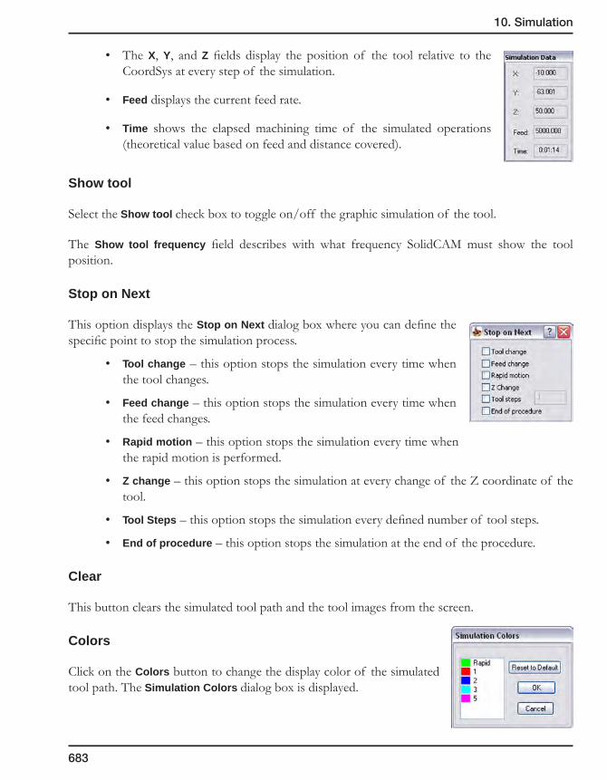
10. Simulation
683
• The X, Y, and Z fields display the position of the tool relative to the CoordSys at every step of the simulation.
• Feed displays the current feed rate.
• Time shows the elapsed machining time of the simulated operations (theoretical value based on feed and distance covered).
Show tool
Select the Show tool check box to toggle on/off the graphic simulation of the tool.
The Show tool frequency field describes with what frequency SolidCAM must show the tool position.
Stop on Next
This option displays the Stop on Next dialog box where you can define the specific point to stop the simulation process.
• Tool change – this option stops the simulation every time when the tool changes.
• Feed change – this option stops the simulation every time when the feed changes.
• Rapid motion – this option stops the simulation every time when the rapid motion is performed.
• Z change – this option stops the simulation at every change of the Z coordinate of the tool.
• Tool Steps – this option stops the simulation every defined number of tool steps.
• End of procedure – this option stops the simulation at the end of the procedure.
Clear
This button clears the simulated tool path and the tool images from the screen.
Colors
Click on the Colors button to change the display color of the simulated tool path. The Simulation Colors dialog box is displayed.
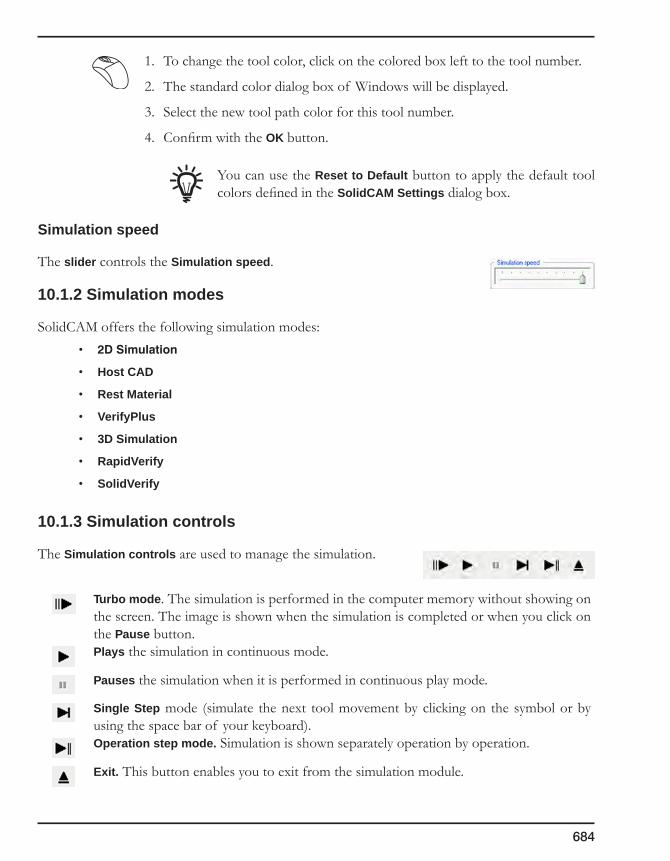
684
1. To change the tool color, click on the colored box left to the tool number.
2. The standard color dialog box of Windows will be displayed.
3. Select the new tool path color for this tool number.
4. Confirm with the OK button.
You can use the Reset to Default button to apply the default tool colors defined in the SolidCAM Settings dialog box.
Simulation speed
The slider controls the Simulation speed.
10.1.2 Simulation modes
SolidCAM offers the following simulation modes:• 2DSimulation
• Host CAD
• Rest Material
• VerifyPlus
• 3D Simulation
• RapidVerify
• SolidVerify
10.1.3 Simulation controls
The Simulation controls are used to manage the simulation.
Turbo mode. The simulation is performed in the computer memory without showing on the screen. The image is shown when the simulation is completed or when you click on the Pause button.Plays the simulation in continuous mode.
Pauses the simulation when it is performed in continuous play mode.
Single Step mode (simulate the next tool movement by clicking on the symbol or by using the space bar of your keyboard).Operation step mode. Simulation is shown separately operation by operation.
Exit. This button enables you to exit from the simulation module.

10. Simulation
685
10.2 2D simulation mode
This simulation mode enables you to display the tool path in the projection view. This feature is useful in prismatic parts machining.
10.2.1 Simulation toolbar
The icons in the toolbar enable you to zoom and pan the simulation picture.
10.2.2 Simulation control panel
Erase on Z change
This option automatically clears the image after every Z change of the tool.
Projection
This option enables you to display the simulation on a Top view projection of the CAD model. When you choose this option, the following dialog box is displayed:

686
Define
This option enables you to define entities of the CAD model that are taken into account in the Top view projection. When you choose this option, the following dialog box is displayed:
• Selectedges
The Select option enables you to select the edges of the CAD model by the Box, Pick or All edges options.
The Unselect option enables you to unselect the previously selected edges.
• SelectionFilter
This option enables you to select edges on a specific Z-level. When you choose this option you can either pick the Z-level with the cursor on the model or you can enter the Z-level in the dialog box. Once you specify the Z-level, only those edges on that level will be picked.
• Selectedgesby
Box – this option enables you to select/unselect edges by enclosing them with a box.
Pick – this option enables you to select/unselect the edges one by one.
All edges – this option automatically selects/unselects all the edges.
• Finish
This option enables you to build the chain after you pick the edges.
• Cancel
This option enables you to exit this dialog box.
Delete
This option enables you to delete what you had previously defined.
Show on model
This option enables you to see the geometry that was selected in the CAD model.
Show
This option enables you to see the model on the simulation screen.

10. Simulation
687
10.3 VerifyPlus simulation mode
This simulation mode provides you with additional verification capabilities:
• 4/5 axes multi-sided solid simulation.
• Simultaneous 4-axis solid simulation.
• 2-D turning solid simulation.
• Turning with mill driven tools solid simulation.
10.3.1 Simulation toolbar
The toolbar enables you to control the simulation in this mode.
Setup and Simulation modes
VerifyPlus has two working modes: for Setup and for Simulation.
• Setupmode
In this mode VerifyPlus enables you to specify the scale and orientation of the model.
• Simulationmode
After setup, switch to the simulation mode. VerifyPlus shades the prepared block and prepares it for simulation.
In this mode, machining can be simulated with standard SolidCAM simulation controls. In this mode all controls for setup of the simulation (scale and orientation) are disabled. You can turn on/off the visualization of tool and also specify the tool visualization as either wireframe or shaded. You can also rotate the display and define the light controls.

688
10.3.2 Buttons available in the Setup mode
Fit to window
Fits the CAM-Part to the entire screen.Fit by box
The area you want to view in the simulation screen is defined by box.Move
Moves the CAM-Part to any point on the screen.Rotate
Rotates the model.Zoom
Zooms in/out the image on the screen.Machine orientation
This button enables you to flip the CAM-Part back and forth by 90 degrees. This option is needed to do realistic simulation on vertical/horizontal machines.
Horizontal machine simulationVertical machine simulation
Isometric views buttons
These buttons enable you to view the CAM-Part in the left, right, back or front isometric views.View buttons
These buttons enable you to view the CAM-Part in the top, left, back, bottom, right or front views.Show/Hide Tool button
Pressing this button enables you to show or hide the tool during simulation. This option is also available in the simulation mode.

10. Simulation
689
Wire Tool/Shaded Tool
These buttons enable you to see the tool as a wire frame tool or as a solid tool.
Shaded tool simulation Wireframe tool simulation
The wireframe tool will always be seen in it entirety, whereas the solid tool is partially hidden by the CAM-Part.
Show/Hide Tool Holder
This button is active in turning only. When pressed, it allows you to see the holder of the turning tool.
Section View
This button is active in Turning only. When pressed, it allows you to see the whole CAM-Part or with a quarter cut away.
Section view mode Normal mode
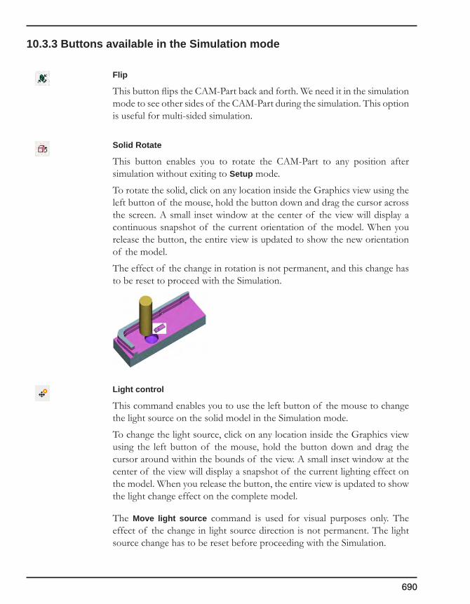
690
10.3.3 Buttons available in the Simulation mode
Flip
This button flips the CAM-Part back and forth. We need it in the simulation mode to see other sides of the CAM-Part during the simulation. This option is useful for multi-sided simulation.
Solid Rotate
This button enables you to rotate the CAM-Part to any position after simulation without exiting to Setup mode.
To rotate the solid, click on any location inside the Graphics view using the left button of the mouse, hold the button down and drag the cursor across the screen. A small inset window at the center of the view will display a continuous snapshot of the current orientation of the model. When you release the button, the entire view is updated to show the new orientation of the model.
The effect of the change in rotation is not permanent, and this change has to be reset to proceed with the Simulation.
Light control
This command enables you to use the left button of the mouse to change the light source on the solid model in the Simulation mode.
To change the light source, click on any location inside the Graphics view using the left button of the mouse, hold the button down and drag the cursor around within the bounds of the view. A small inset window at the center of the view will display a snapshot of the current lighting effect on the model. When you release the button, the entire view is updated to show the light change effect on the complete model.
The Move light source command is used for visual purposes only. The effect of the change in light source direction is not permanent. The light source change has to be reset before proceeding with the Simulation.

10. Simulation
691
10.4 Host CAD simulation mode
This simulation mode enables you to display the tool path directly on the model in the SolidWorks window. Since all the View options of SolidWorks are active during the simulation, you can see the tool path from different perspectives and zoom in on a certain area of the model.

692
10.5 3D simulation mode
This simulation mode enables you to display the tool path on the 3D model using all the graphic acceleration functionality of OpenGL. The target model must be defined to use this simulation mode. For more information on the Target model, see topic 2.4.2.
10.5.1 Simulation toolbar
SolidCAM enables you to use the toolbar to control the simulation in this mode.
The following buttons are available in this toolbar:
• These buttons are used for model scaling, panning and rotating.
• This button enables you to remove the simulated tool path from the screen.
• With this button you can toggle on/off the tool visualization during the simulation.
• This button enables you to switch the graphic screen between three modes:
• Tool path only simulation
• Tool path and model simulation
• Model only simulation
• These buttons enable you to show the model in the projection views (Left, Right, Top, etc.)
• This button returns the original position and orientation of the model.
• These buttons switch the simulation to 4/1 view mode.

10. Simulation
693
• This button enables you to show the Zoom Window with the enlarged image of the model and tool path fragment centered on the mouse position. You can control the zoom factor in the Zoom Window.
• These buttons enable you to show the dynamic section of the model. The section slider will be displayed in the graphic area. By moving this slider you can control the section.
10.5.2 Simulation menu
Options
Clear tool path
This command enables you to remove the simulated tool path from the screen.
Show/Hide Tool Path
With this command you can toggle on/off the tool path visualization during the simulation.
Copy to clipboard
This command enables you to copy the simulation image into the Windows clipboard for future reference.

694
Settings
Visual properties
The Visual Properties dialog box enables you to edit the visual properties of 3D Simulation mode.
• Target Model. SolidCAM enables you to choose the color of the Target model and set its transparency.
• Tool. SolidCAM enables you to choose the color of the tool and set its transparency.
• Background. SolidCAM enables you to choose the background color.
• Tool path. The Smooth (Wide) lines option enables you to perform smoothing of the tool path lines (anti-aliasing).
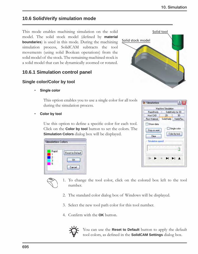
10. Simulation
695
10.6 SolidVerify simulation mode
This mode enables machining simulation on the solid model. The solid stock model (defined by material boundaries) is used in this mode. During the machining simulation process, SolidCAM subtracts the tool movements (using solid Boolean operations) from the solid model of the stock. The remaining machined stock is a solid model that can be dynamically zoomed or rotated.
10.6.1 Simulation control panel
Single color/Color by tool
• Singlecolor
This option enables you to use a single color for all tools during the simulation process.
• Colorbytool
Use this option to define a specific color for each tool. Click on the Color by tool button to set the colors. The Simulation Colors dialog box will be displayed.
1. To change the tool color, click on the colored box left to the tool number.
2. The standard color dialog box of Windows will be displayed.
3. Select the new tool path color for this tool number.
4. Confirm with the OK button.
You can use the Reset to Default button to apply the default tool colors, as defined in the SolidCAM Settings dialog box.
Solid stock model
Solid tool

696
10.6.2 Simulation toolbar
The toolbar below enables you to control the simulation in this mode.
Available buttons:
Fit to window
Fits the CAM-Part to the entire screen.
Fit by box
The area you want to view in the simulation screen is defined by a box.Move
Moves the CAM-Part to any point on the screen.
Rotate
Rotates the model.
Zoom
Zooms in/out the image on the screen.
Selection mode
The Selection mode enables you to select the solid bodies in the graphic area. The selected body will be highlighted. The right-click menu is available for each selected solid body.
For more information on the Selection mode, see topic 10.6.3.
Measurement
The Measurement function enables you to measure distances directly on the solid bodies in the SolidVerify window. This enables checking the linear dimensions of the part during simulation.
For more information on the Measurement, see topic 10.6.4.
Light control
This command enables you to use the left button of the mouse to change the light source on the solid model in the Simulation mode.
To change the light source, click in the graphic area and drag the cursor around within the bounds of the view.

10. Simulation
697
View buttons
These icons enable you to show the model in the projection views (Left, Right, Top etc.).Render mode
Displays a shaded view of the model.
Hybrid mode
Displays a transparent view of the model.
Wire mode
Displays the CAM-Part and tool movements in wireframe mode.
Hidden line mode
Displays the CAM-Part and the tool movements in hidden-line wireframe mode.

698
Redraw
Redraws the view.Show/Hide Machined Stock
Shows/hides the machined stock model.Show/Hide Target
Shows/hides the target model.Show/Hide Rest Material
Shows/hides the rest material on the machined stock model.
Show/Hide Split Solids
This option displays the Show/Hide Split solids dialog box.
This dialog box enables you to switch between split solids during the simulation and enables you to remove the pieces of material that have been cut away during the machining.Show/Hide Gouges
Shows gouges of the target model. Split Gouges
This option displays the Show/Hide Split solids dialog box. This dialog box enables you to switch between split solids of gouge areas during the simulation and enables you to check separately the areas of the gouge.
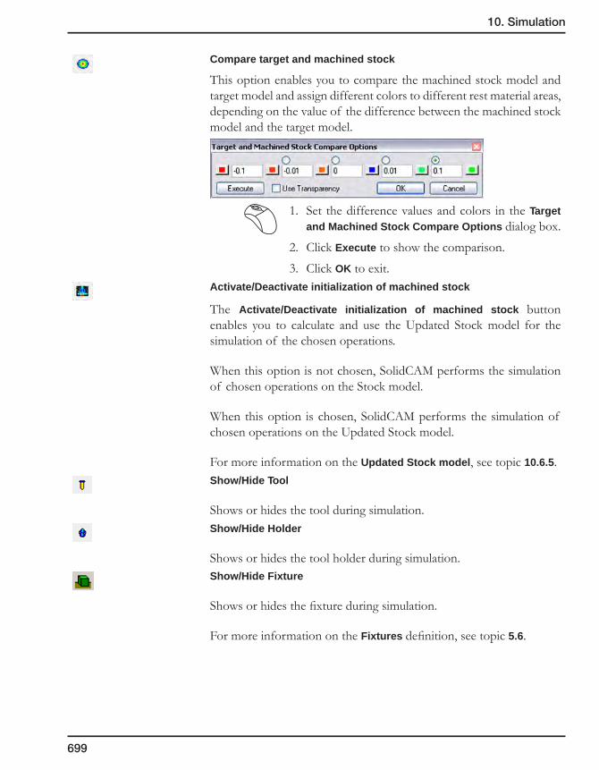
10. Simulation
699
Compare target and machined stock
This option enables you to compare the machined stock model and target model and assign different colors to different rest material areas, depending on the value of the difference between the machined stock model and the target model.
1. Set the difference values and colors in the Target and Machined Stock Compare Options dialog box.
2. Click Execute to show the comparison.
3. Click OK to exit.Activate/Deactivate initialization of machined stock
The Activate/Deactivate initialization of machined stock button enables you to calculate and use the Updated Stock model for the simulation of the chosen operations.
When this option is not chosen, SolidCAM performs the simulation of chosen operations on the Stock model.
When this option is chosen, SolidCAM performs the simulation of chosen operations on the Updated Stock model.
For more information on the Updated Stock model, see topic 10.6.5.Show/Hide Tool
Shows or hides the tool during simulation.Show/Hide Holder
Shows or hides the tool holder during simulation.Show/Hide Fixture
Shows or hides the fixture during simulation.
For more information on the Fixtures definition, see topic 5.6.

700
Save the simulation model
This field enables you to save the current model of the material removal in STL format.
This field is active only when the Manual method of the Rest material update are chosen.
For more information on this subject, see topic 2.4.Load the simulation model
This field enables you to load the previously saved model of the material removal. The simulation will be performed on the loaded model.
This field is active only when the Manual method of the Rest material update are chosen.
For more information on this subject, see topic 2.4.
10.6.3 Selection mode
The Selection mode enables you to select solid bodies in the SolidVerify simulation window. The selected body will be highlighted. The right-clicking on the selected solid body provides the following commands:
View
This submenu enables you to choose the view operation commands (Fit, Move, Rotate etc.). These commands are also available in the SolidVerify toolbar.
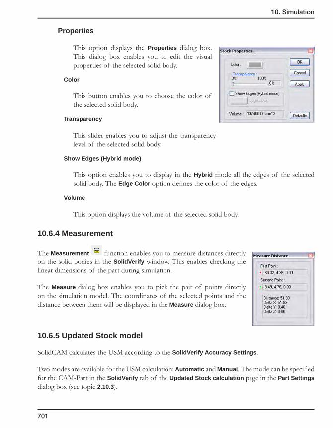
10. Simulation
701
Properties
This option displays the Properties dialog box. This dialog box enables you to edit the visual properties of the selected solid body.
Color
This button enables you to choose the color of the selected solid body.
Transparency
This slider enables you to adjust the transparency level of the selected solid body.
Show Edges (Hybrid mode)
This option enables you to display in the Hybrid mode all the edges of the selected solid body. The Edge Color option defines the color of the edges.
Volume
This option displays the volume of the selected solid body.
10.6.4 Measurement
The Measurement function enables you to measure distances directly on the solid bodies in the SolidVerify window. This enables checking the linear dimensions of the part during simulation.
The Measure dialog box enables you to pick the pair of points directly on the simulation model. The coordinates of the selected points and the distance between them will be displayed in the Measure dialog box.
10.6.5 Updated Stock model
SolidCAM calculates the USM according to the SolidVerify Accuracy Settings.
Two modes are available for the USM calculation: Automatic and Manual. The mode can be specified for the CAM-Part in the SolidVerify tab of the Updated Stock calculation page in the Part Settings dialog box (see topic 2.10.3).
702
• Automaticmode
In the Automatic mode, SolidCAM automatically calculates the USM for the operations chosen for the simulation.
To generate USM for the chosen operation, SolidCAM runs the SolidVerify simulation of all the previous operations in an invisible mode. The resulting USM is saved in *.stf file in the CAM-Part folder.
During the USM calculation process for the current operation, SolidCAM generates intermediate USM files for the previous operations and saves them according to the Updated Stock calculation settings. Saved USM files can be used in further SolidVerify simulations.
If the USM file for some operation already exists, SolidCAM checks the compliance between accuracy settings of the USM and SolidVerify Accuracy Settings of the CAM-Part. If these settings concur, SolidCAM uses the existing USM, otherwise the USM will be recalculated in accordance with the CAM-Part settings.
The Delete Updated Stock files command in the Settings menu of the SolidVerify simulation enables you to erase all the USM files of the current CAM-Part.
This command is unavailable in the Manual mode.
• Manualmode
In the Manual mode, SolidCAM enables you to manually save the USM after the SolidVerify simulation and use it for additional simulations.
When the Manual mode is chosen, the Save Machined stock to file and Load Machined stock from file buttons are available in the SolidVerify simulation toolbar (see topic 10.6.2).
When the simulation for a separate operation or for a number of operations is performed, the Save Machined stock to file button enables you to save the USM in the *.stf file. The name of the file is the same as the name of the last simulated operation.
SolidCAM enables you to load the USM of previous operation (if it was saved) with the Load Machined stock from file button and perform the simulation on it.
SolidCAM automatically deletes USM files for the specific operation when:
• the operation was deleted;
• the operation was changed and caused the deletion of the operation PCode;
• the operation sequence was changed;
• the accuracy parameters were changed;
• the working mode was changed from Manual to Automatic.

10. Simulation
703
Updated Stock Model interchangeability
Updated Stock models generated for the SolidVerify simulation and for 3D Milling of Rest material areas are interchangeable. This means that SolidCAM can use USM files generated for the SolidVerify simulation instead of USM files for 3D Milling and vice versa.
If the USM file for 3D Milling is already generated for some operation it can be used also for SolidVerify simulation if the Accuracy settings of the USM match the SolidVerify Accuracy Settings of the CAM-Part.
10.6.6 Simulation menu
This menu is common for SolidVerify, SolidVerify for 3D and RapidVerify simulation modes.
File
• Open
Open machined stock from FCT
This option enables you to load the machined stock model from the SolidCAM FCT file (*.fct).
Open machined stock from STL
This option enables you to load the machined stock model from the Stereolithography file (*.stl).
• Save
Save machined stock to FCT
This option enables you to save the machined stock model to the SolidCAM FCT file (*.fct).
Save machined stock to STL
This option enables you to save the machined stock model to the Stereolithography file (*.stl).
Options
• Comparetargetandmachinedstock
This option enables you to compare the stock model and target model and assign different colors to different rest material areas, depending on their tolerance (see topic 2.4).

704
• MachinedStockMeasurements
This option displays the Machined Stock Measurements dialog box where you can see the dimensions and the volume of the Machined stock model.
This option is available in the SolidVerify simulation mode only.
Settings
Visual properties
This option enables you to define colors and transparency for the simulation. The Visual Properties dialog box will be displayed.
The Use CAD background color check box enables you to apply the simulation background color provided by the CAD system.
The Use Gradient background check box enables you to apply the gradient background to the graphics area. Specify colors for Top Background Color and Bottom Background Color.
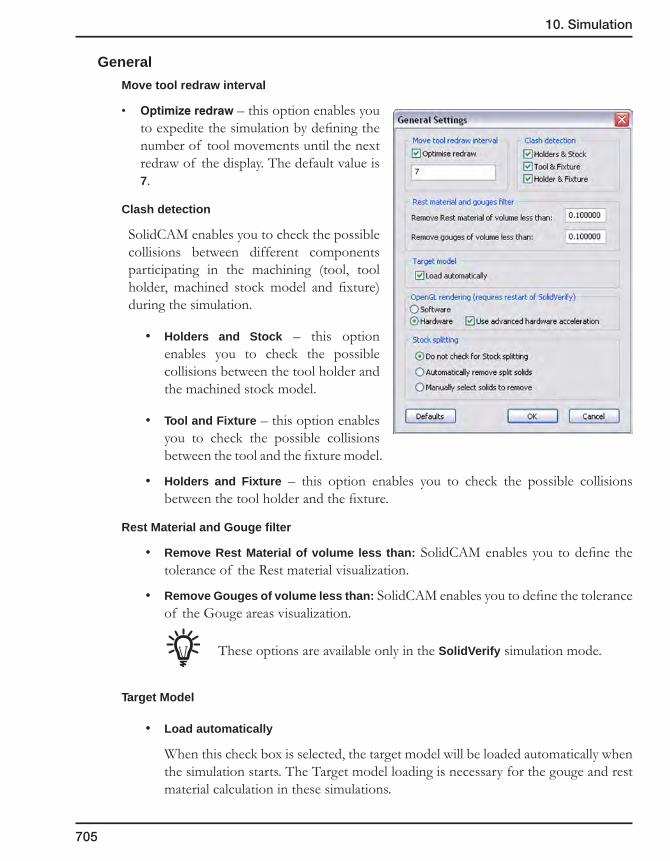
10. Simulation
705
General
Move tool redraw interval
• Optimizeredraw– this option enables you to expedite the simulation by defining the number of tool movements until the next redraw of the display. The default value is 7.
Clash detection
SolidCAM enables you to check the possible collisions between different components participating in the machining (tool, tool holder, machined stock model and fixture) during the simulation.
• Holders and Stock – this option enables you to check the possible collisions between the tool holder and the machined stock model.
• Tool and Fixture – this option enables you to check the possible collisions between the tool and the fixture model.
• Holders and Fixture – this option enables you to check the possible collisions between the tool holder and the fixture.
Rest Material and Gouge filter
• Remove Rest Material of volume less than: SolidCAM enables you to define the tolerance of the Rest material visualization.
• Remove Gouges of volume less than: SolidCAM enables you to define the tolerance of the Gouge areas visualization.
These options are available only in the SolidVerify simulation mode.
Target Model
• Load automatically
When this check box is selected, the target model will be loaded automatically when the simulation starts. The Target model loading is necessary for the gouge and rest material calculation in these simulations.
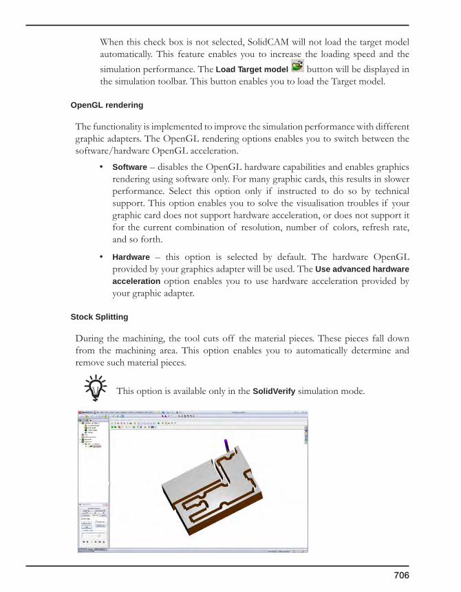
706
When this check box is not selected, SolidCAM will not load the target model automatically. This feature enables you to increase the loading speed and the simulation performance. The Load Target model button will be displayed in the simulation toolbar. This button enables you to load the Target model.
OpenGL rendering
The functionality is implemented to improve the simulation performance with different graphic adapters. The OpenGL rendering options enables you to switch between the software/hardware OpenGL acceleration.
• Software – disables the OpenGL hardware capabilities and enables graphics rendering using software only. For many graphic cards, this results in slower performance. Select this option only if instructed to do so by technical support. This option enables you to solve the visualisation troubles if your graphic card does not support hardware acceleration, or does not support it for the current combination of resolution, number of colors, refresh rate, and so forth.
• Hardware – this option is selected by default. The hardware OpenGL provided by your graphics adapter will be used. The Use advanced hardware acceleration option enables you to use hardware acceleration provided by your graphic adapter.
Stock Splitting
During the machining, the tool cuts off the material pieces. These pieces fall down from the machining area. This option enables you to automatically determine and remove such material pieces.
This option is available only in the SolidVerify simulation mode.
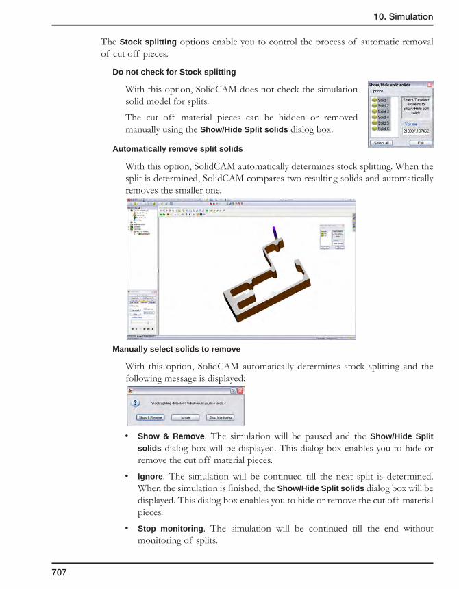
10. Simulation
707
The Stock splitting options enable you to control the process of automatic removal of cut off pieces.
Do not check for Stock splitting
With this option, SolidCAM does not check the simulation solid model for splits.
The cut off material pieces can be hidden or removed manually using the Show/Hide Split solids dialog box.
Automatically remove split solids
With this option, SolidCAM automatically determines stock splitting. When the split is determined, SolidCAM compares two resulting solids and automatically removes the smaller one.
Manually select solids to remove
With this option, SolidCAM automatically determines stock splitting and the following message is displayed:
• Show&Remove. The simulation will be paused and the Show/Hide Split solids dialog box will be displayed. This dialog box enables you to hide or remove the cut off material pieces.
• Ignore. The simulation will be continued till the next split is determined. When the simulation is finished, the Show/Hide Split solids dialog box will be displayed. This dialog box enables you to hide or remove the cut off material pieces.
• Stop monitoring. The simulation will be continued till the end without monitoring of splits.

708
Accuracy
This option is available only in the SolidVerify simulation mode.
Tool facet tolerance
This option controls the precision of the tool for the simulation.
This parameter defines the precision of the facets of a tool in mm (or inches). Since this is an absolute value, the facets tolerance for the small and large tools will be the same. This tolerance will influence the quality of the simulation. The quality of the simulation will be the same for large tools and small tools. The speed of the simulation will be relative to the tool. The simulation of the larger tool will be slower.
Tool facet type
As well as changing the tolerance used for faceting, the application controls the manner in which the faceted tool representation approximates the tool by forcing the representation to be bigger or smaller than the actual tool. For example, if you want to know whether the tool gouged the target part, then it would be preferable for SolidVerify to have a tool representation that was guaranteed to lie outside the bounds of the actual tool.
• Internal – The tool representation lies within the actual tool. The vertices of the tool representation will lie on the surface of the actual tool and the facets will lie within the actual tool.
• External – The actual tool lies within the tool representation. The vertices will lie at distances up to the faceting tolerance from the surface of the actual tool.
• Mixed – This is a combination of Internal and External. The vertices lie outside the actual tool but parts of the facets may lie inside it. This mode is the default and should be used unless there is a specific reason for using one of the other modes as it generates fewer facets and will therefore be faster.
5 Axis
• Linear interpolation. This option enables you to perform the linear interpolation of 5 axis tool movement. The Max. Interpolation Angle value defines the angular tolerance for the interpolation.
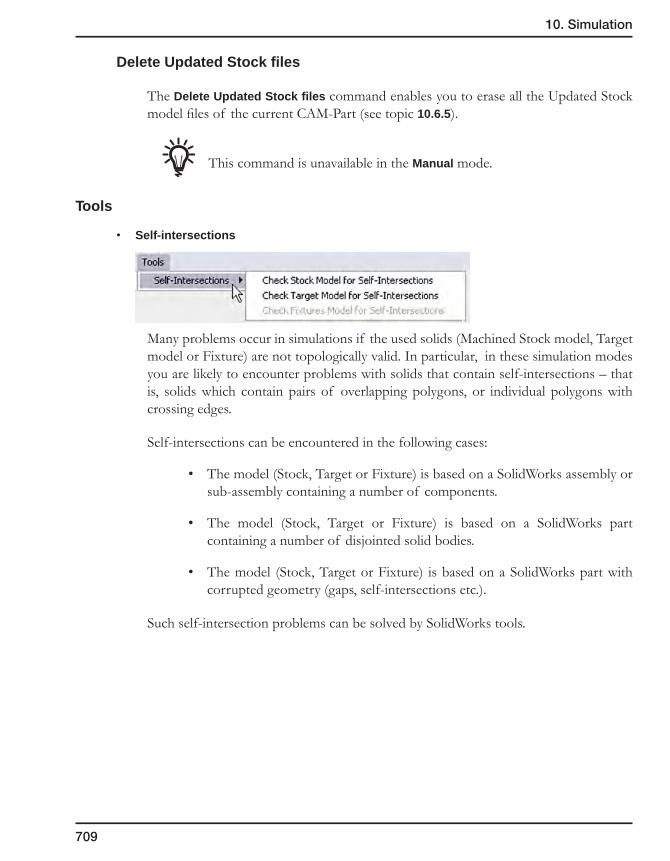
10. Simulation
709
Delete Updated Stock files
The Delete Updated Stock files command enables you to erase all the Updated Stock model files of the current CAM-Part (see topic 10.6.5).
This command is unavailable in the Manual mode.
Tools
• Self-intersections
Many problems occur in simulations if the used solids (Machined Stock model, Target model or Fixture) are not topologically valid. In particular, in these simulation modes you are likely to encounter problems with solids that contain self-intersections – that is, solids which contain pairs of overlapping polygons, or individual polygons with crossing edges.
Self-intersections can be encountered in the following cases:
• The model (Stock, Target or Fixture) is based on a SolidWorks assembly or sub-assembly containing a number of components.
• The model (Stock, Target or Fixture) is based on a SolidWorks part containing a number of disjointed solid bodies.
• The model (Stock, Target or Fixture) is based on a SolidWorks part with corrupted geometry (gaps, self-intersections etc.).
Such self-intersection problems can be solved by SolidWorks tools.
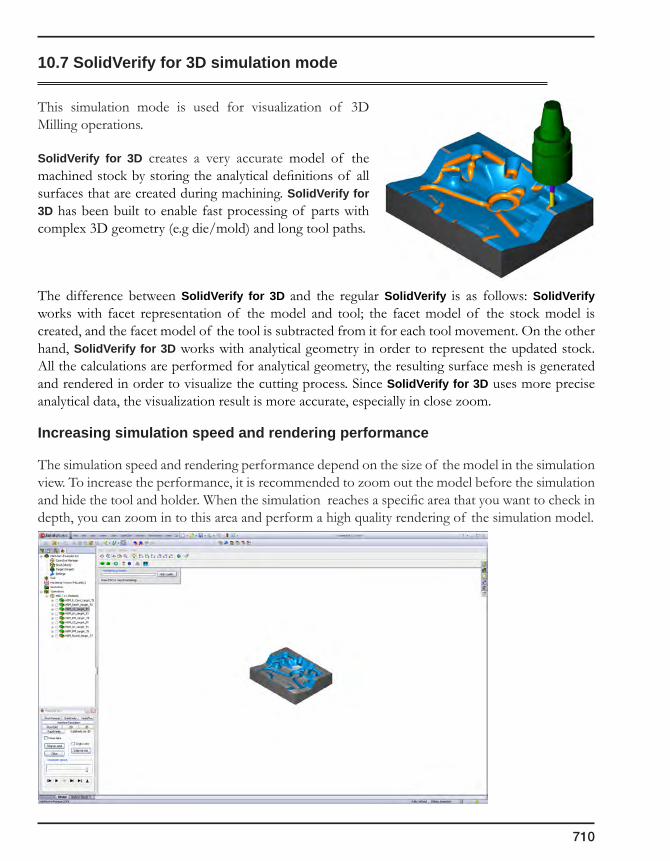
710
10.7 SolidVerify for 3D simulation mode
This simulation mode is used for visualization of 3D Milling operations.
SolidVerify for 3D creates a very accurate model of the machined stock by storing the analytical definitions of all surfaces that are created during machining. SolidVerify for 3D has been built to enable fast processing of parts with complex 3D geometry (e.g die/mold) and long tool paths.
The difference between SolidVerify for 3D and the regular SolidVerify is as follows: SolidVerify works with facet representation of the model and tool; the facet model of the stock model is created, and the facet model of the tool is subtracted from it for each tool movement. On the other hand, SolidVerify for 3D works with analytical geometry in order to represent the updated stock. All the calculations are performed for analytical geometry, the resulting surface mesh is generated and rendered in order to visualize the cutting process. Since SolidVerify for 3D uses more precise analytical data, the visualization result is more accurate, especially in close zoom.
Increasing simulation speed and rendering performance
The simulation speed and rendering performance depend on the size of the model in the simulation view. To increase the performance, it is recommended to zoom out the model before the simulation and hide the tool and holder. When the simulation reaches a specific area that you want to check in depth, you can zoom in to this area and perform a high quality rendering of the simulation model.

10. Simulation
711
10.7.1 Simulation control panel
The Simulation control panel is similar to that of the SolidVerify simulation mode (see topic 10.6.1).
10.7.2 Rendering of the simulation model
Rendering of the simulation model is performed in two modes:
Facet rendering
In this mode, a draft quality rendering of the model is performed. This mode is used in the process of view manipulations (zooming, panning and rotating).
The settings of this mode can be controlled in the Facet rendering section of the View Settings dialog box. This dialog box is available by clicking on the View Settings item in the Settings menu.
The Facet rendering section contains the slider that enables you to control the quality and speed of the rendering, moving from faster draft quality to slower but higher quality.
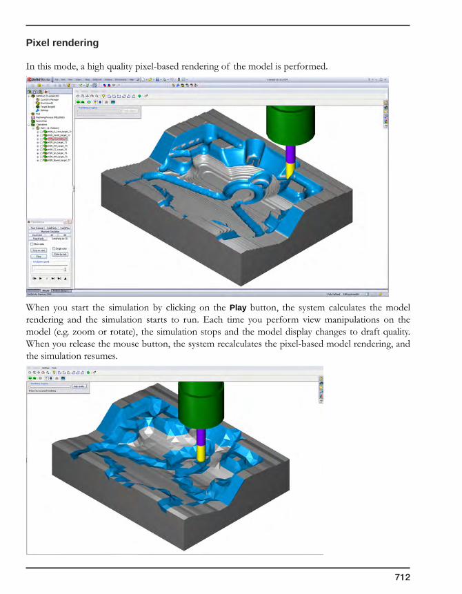
712
Pixel rendering
In this mode, a high quality pixel-based rendering of the model is performed.
When you start the simulation by clicking on the Play button, the system calculates the model rendering and the simulation starts to run. Each time you perform view manipulations on the model (e.g. zoom or rotate), the simulation stops and the model display changes to draft quality. When you release the mouse button, the system recalculates the pixel-based model rendering, and the simulation resumes.
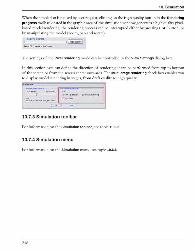
10. Simulation
713
When the simulation is paused by user request, clicking on the High quality button in the Rendering progress toolbar located in the graphic area of the simulation window generates a high quality pixel-based model rendering; the rendering process can be interrupted either by pressing ESC button, or by manipulating the model (zoom, pan and rotate).
The settings of the Pixel rendering mode can be controlled in the View Settings dialog box.
In this section, you can define the direction of rendering: it can be performed from top to bottom of the screen or from the screen center outwards. The Multi-stage rendering check box enables you to display model rendering in stages, from draft quality to high quality.
10.7.3 Simulation toolbar
For information on the Simulation toolbar, see topic 10.6.2.
10.7.4 Simulation menu
For information on the Simulation menu, see topic 10.6.6.
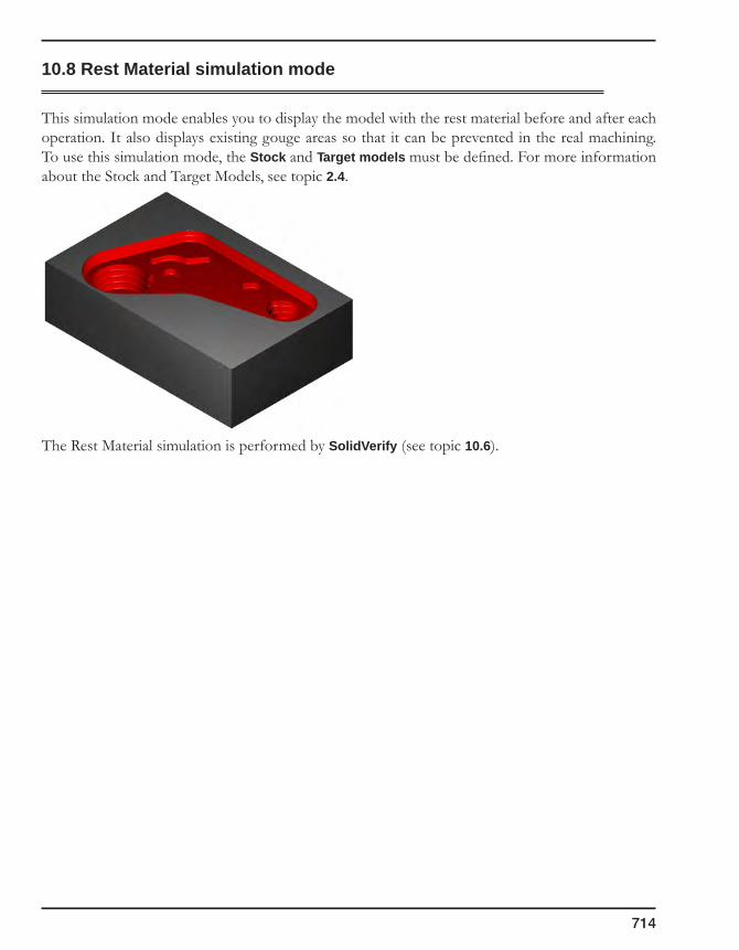
714
10.8 Rest Material simulation mode
This simulation mode enables you to display the model with the rest material before and after each operation. It also displays existing gouge areas so that it can be prevented in the real machining. To use this simulation mode, the Stock and Target models must be defined. For more information about the Stock and Target Models, see topic 2.4.
The Rest Material simulation is performed by SolidVerify (see topic 10.6).

10. Simulation
715
10.9 RapidVerify simulation mode
The RapidVerify simulation mode enables you to quickly simulate 3-axis tool path containing a great amount of tool movements. The major application of this mode is verification of the tool path generated by 3D Milling (see сhapter 7) or SolidCAM HSM operations (see SolidCAM HSM Module User Guide).
RapidVerify provides high performance because it uses a simplified representation, as opposed to the solid representation used by SolidVerify (see topic 10.6). The limitation of this simulation mode is that the machined part cannot have any concavities in the Z-direction – in other words, for any X, Y point on the machined part there is only one Z-value. Therefore, multi-sided 4- and 5-axis machining cannot be simulated using RapidVerify. The shaped tools are also not supported; only end mills, bull-nosed, ball-nosed and taper tools can be used in the operations that are simulated with RapidVerify.
10.9.1 RapidVerify control panel
The RapidVerify data structure is based on a grid of material height values. The resolution of this grid can be modified by the Grid Resolution slider. Greater resolution will improve verification accuracy but at the expense of slower graphical update and increased memory usage.
Using the Speed-up Animation option, SolidCAM enables you to increase the simulation speed by simplifying the intermediate simulation images. When this option is turned on, SolidCAM merges a specified number of facets into a single one; the Facet Merging parameter enables you to define the number of neighbouring facets that are merged together. The simplified model is displayed during the simulation, resulting in accelerated rendering and refreshing. When the simulation is paused or finished, the non-simplified machined stock is displayed. The simplified image is also displayed during pan, zoom or rotate operations.
There are two possible scenarios for using the RapidVerify simulation mode:
1. For the fastest verification, use Turbo mode and click on the right mouse button (or rotate/pan) to get intermediate updated stock; you do not need to use the Speed-Up Animation option in this scenario.
2. For regular verification, set the Speed-up Animation option to a higher number for Facet Merging; you will see a continuous verification on a not so clear model. Whenever you stop the verification you will see an accurate model representation.
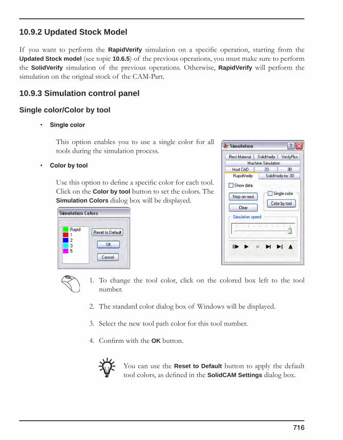
716
10.9.2 Updated Stock Model
If you want to perform the RapidVerify simulation on a specific operation, starting from the Updated Stock model (see topic 10.6.5) of the previous operations, you must make sure to perform the SolidVerify simulation of the previous operations. Otherwise, RapidVerify will perform the simulation on the original stock of the CAM-Part.
10.9.3 Simulation control panel
Single color/Color by tool
• Singlecolor
This option enables you to use a single color for all tools during the simulation process.
• Colorbytool
Use this option to define a specific color for each tool. Click on the Color by tool button to set the colors. The Simulation Colors dialog box will be displayed.
1. To change the tool color, click on the colored box left to the tool number.
2. The standard color dialog box of Windows will be displayed.
3. Select the new tool path color for this tool number.
4. Confirm with the OK button.
You can use the Reset to Default button to apply the default tool colors, as defined in the SolidCAM Settings dialog box.
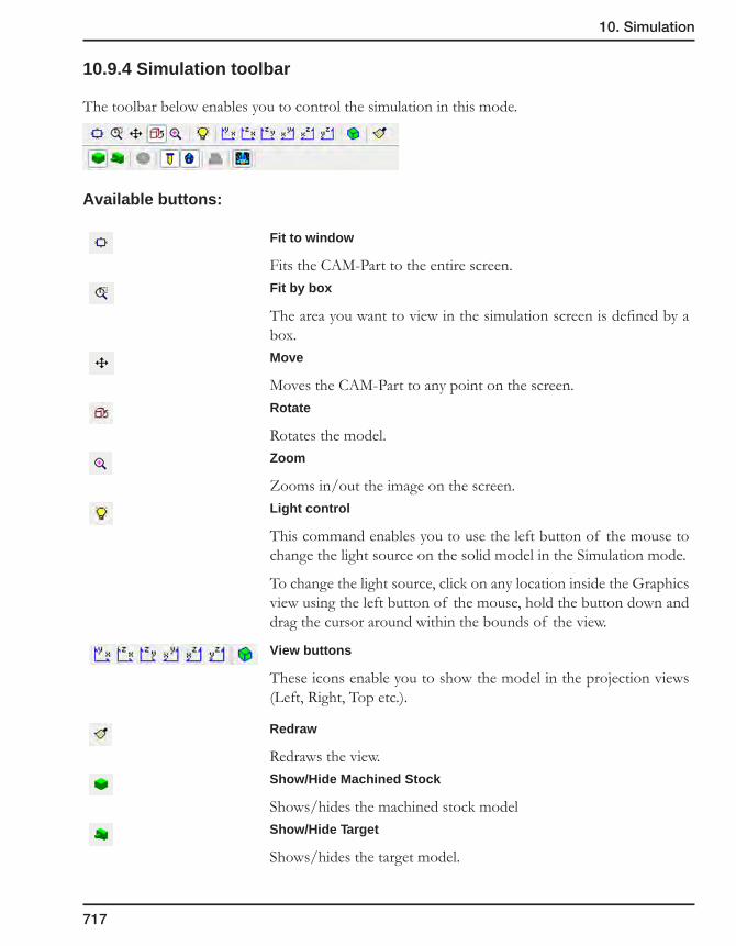
10. Simulation
717
10.9.4 Simulation toolbar
The toolbar below enables you to control the simulation in this mode.
Available buttons:
Fit to window
Fits the CAM-Part to the entire screen.Fit by box
The area you want to view in the simulation screen is defined by a box.Move
Moves the CAM-Part to any point on the screen.Rotate
Rotates the model.Zoom
Zooms in/out the image on the screen.Light control
This command enables you to use the left button of the mouse to change the light source on the solid model in the Simulation mode.
To change the light source, click on any location inside the Graphics view using the left button of the mouse, hold the button down and drag the cursor around within the bounds of the view.
View buttons
These icons enable you to show the model in the projection views (Left, Right, Top etc.).
Redraw
Redraws the view.Show/Hide Machined Stock
Shows/hides the machined stock modelShow/Hide Target
Shows/hides the target model.

718
Compare target and machined stock
This option enables you to compare the machined stock model and target model and assign different colors to different rest material areas, depending on the value of the difference between the machined stock model and the target model.
1. Set the difference values and colors in the Target and Machined Stock Compare Options dialog box.
2. Click Execute to show the comparison.
3. Click OK to exit.
Activate/Deactivate initialization of machined stock
The Activate/Deactivate initialization of machined stock button enables you to calculate and use the Updated Stock model for the simulation of the chosen operations.
When this option is not chosen, SolidCAM performs the simulation of chosen operations on the Stock model.
When this option is chosen, SolidCAM performs the simulation of chosen operations on the Updated Stock model.
For more information on the Updated Stock model, see topic 10.6.5.
Show/Hide Tool
Shows or hides the tool during simulation.
Show/Hide Holder
Shows or hides the tool holder during simulation.
Show/Hide Fixture
Shows or hides the fixture during simulation.
For more information on the Fixtures definition, see topic 5.6.
10.9.5 Simulation menu
For information on the Simulation menu, see topic 10.6.6.
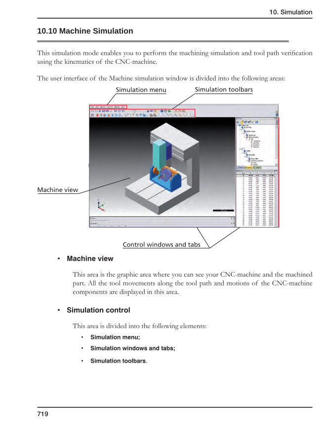
10. Simulation
719
10.10 Machine Simulation
This simulation mode enables you to perform the machining simulation and tool path verification using the kinematics of the CNC-machine.
The user interface of the Machine simulation window is divided into the following areas:
• Machineview
This area is the graphic area where you can see your CNC-machine and the machined part. All the tool movements along the tool path and motions of the CNC-machine components are displayed in this area.
• Simulationcontrol
This area is divided into the following elements:• Simulationmenu;
• Simulationwindowsandtabs;
• Simulationtoolbars.
Simulation menu Simulation toolbars
Machine view
Control windows and tabs

720
10.10.1 Simulation menu
The Windows-style menu located above the graphic area contains the following sets of simulation control options:
File
This menu item contains the file managing commands:
• LoadNCFile
When you perform simulation in the Machine simulation mode, SolidCAM saves all the simulation data in the Output.sim file located in the CAM-Part folder. The Load NC file option enables you to load an existing NC file containing the simulation data.
• CreatePresentation
This option enables you to create a self-extracting executable file containing the current CNC-machine and NC file. When you run the generated executable file, it unpacks in the system temporary folder and displays the standalone MachSimPresentation window.
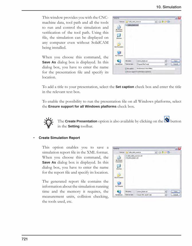
10. Simulation
721
This window provides you with the CNC-machine data, tool path and all the tools to run and control the simulation and verification of the tool path. Using this file, the simulation can be displayed on any computer even without SolidCAM being installed.
When you choose this command, the Save As dialog box is displayed. In this dialog box, you have to enter the name for the presentation file and specify its location.
To add a title to your presentation, select the Set caption check box and enter the title in the relevant text box.
To enable the possibility to run the presentation file on all Windows platforms, select the Ensure support for all Windows platforms check box.
The Create Presentation option is also available by clicking on the button in the Setting toolbar.
• CreateSimulationReport
This option enables you to save a simulation report file in the XML format. When you choose this command, the Save As dialog box is displayed. In this dialog box, you have to enter the name for the report file and specify its location.
The generated report file contains the information about the simulation running time and the memory it requires, the measurement units, collision checking, the tools used, etc.

722
View
This menu item contains the commands responsible for the display of the simulation model in the Machine view area.
Fullscreen
This command enables you to extend the simulation window to the entire screen size.
Fit to screen
This command enables you to adjust the simulation model size to the graphic area.
This option is also available as the button in the View toolbar.
Standard Views
This submenu contains commands that enable you to rotate the simulation model to the appropriate standard view.
• Isometric: this button enables you to rotate the simulation model into the isometric view.
• Top: this button enables you to rotate the simulation model into the top side view.
• Front: this button enables you to rotate the simulation model into the front side view.
• Right: this button enables you to rotate the simulation model into the right side view.
• Bottom: this button enables you to rotate the simulation model into the bottom side view.
• Left: this button enables you to rotate the simulation model into the left side view.
• Back: this button enables you to rotate the simulation model into the back side view.
These commands are also available as buttons in the View toolbar.
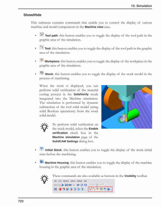
10. Simulation
723
Show/Hide
This submenu contains commands that enable you to control the display of various machine and model components in the Machine view area.
• Tool path: this button enables you to toggle the display of the tool path in the graphic area of the simulation.
• Tool: this button enables you to toggle the display of the tool path in the graphic area of the simulation.
• Workpiece: this button enables you to toggle the display of the workpiece in the graphic area of the simulation.
• Stock: this button enables you to toggle the display of the stock model in the process of machining.
When the stock is displayed, you can perform solid verification of the material cutting process in the SolidVerify mode integrated into the Machine simulation. The simulation is performed by dynamic subtraction of the tool solid model (using solid Boolean operations) from the stock solid model.
To perform solid verification on the stock model, select the Enable verification check box in the Machine simulation page of the SolidCAM Settings dialog box.
• Initial Stock: this button enables you to toggle the display of the stock initial state before the machining.
• Machine Housing: this button enables you to toggle the display of the machine housing in the graphic area of the simulation.
These commands are also available as buttons in the Visibility toolbar.
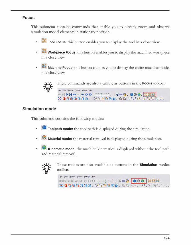
724
Focus
This submenu contains commands that enable you to directly zoom and observe simulation model elements in stationary position.
• Tool Focus: this button enables you to display the tool in a close view.
• Workpiece Focus: this button enables you to display the machined workpiece in a close view.
• Machine Focus: this button enables you to display the entire machine model in a close view.
These commands are also available as buttons in the Focus toolbar.
Simulation mode
This submenu contains the following modes:
• Toolpath mode: the tool path is displayed during the simulation.
• Material mode: the material removal is displayed during the simulation.
• Kinematic mode: the machine kinematics is displayed without the tool path and material removal.
These modes are also available as buttons in the Simulation modes toolbar.
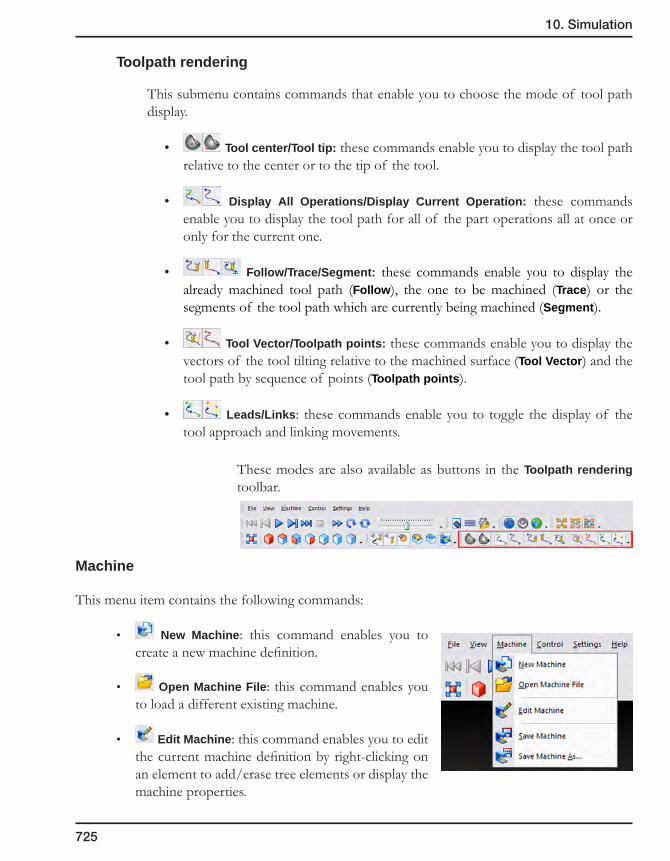
10. Simulation
725
Toolpath rendering
This submenu contains commands that enable you to choose the mode of tool path display.
• Tool center/Tool tip: these commands enable you to display the tool path relative to the center or to the tip of the tool.
• Display All Operations/Display Current Operation: these commands enable you to display the tool path for all of the part operations all at once or only for the current one.
• Follow/Trace/Segment: these commands enable you to display the already machined tool path (Follow), the one to be machined (Trace) or the segments of the tool path which are currently being machined (Segment).
• Tool Vector/Toolpath points: these commands enable you to display the vectors of the tool tilting relative to the machined surface (Tool Vector) and the tool path by sequence of points (Toolpath points).
• Leads/Links: these commands enable you to toggle the display of the tool approach and linking movements.
These modes are also available as buttons in the Toolpath rendering toolbar.
Machine
This menu item contains the following commands:
• New Machine: this command enables you to create a new machine definition.
• Open Machine File: this command enables you to load a different existing machine.
• Edit Machine: this command enables you to edit the current machine definition by right-clicking on an element to add/erase tree elements or display the machine properties.
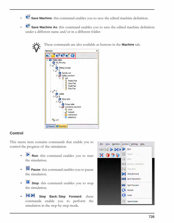
726
• Save Machine: this command enables you to save the edited machine definition.
• Save Machine As: this command enables you to save the edited machine definition under a different name and/or in a different folder.
These commands are also available as buttons in the Machine tab.
Control
This menu item contains commands that enable you to control the progress of the simulation.
• Run: this command enables you to start the simulation.
• Pause: this command enables you to pause the simulation.
• Stop: this command enables you to stop the simulation.
• Step Back/Step Forward: these commands enable you to perform the simulation in the step-by-step mode.
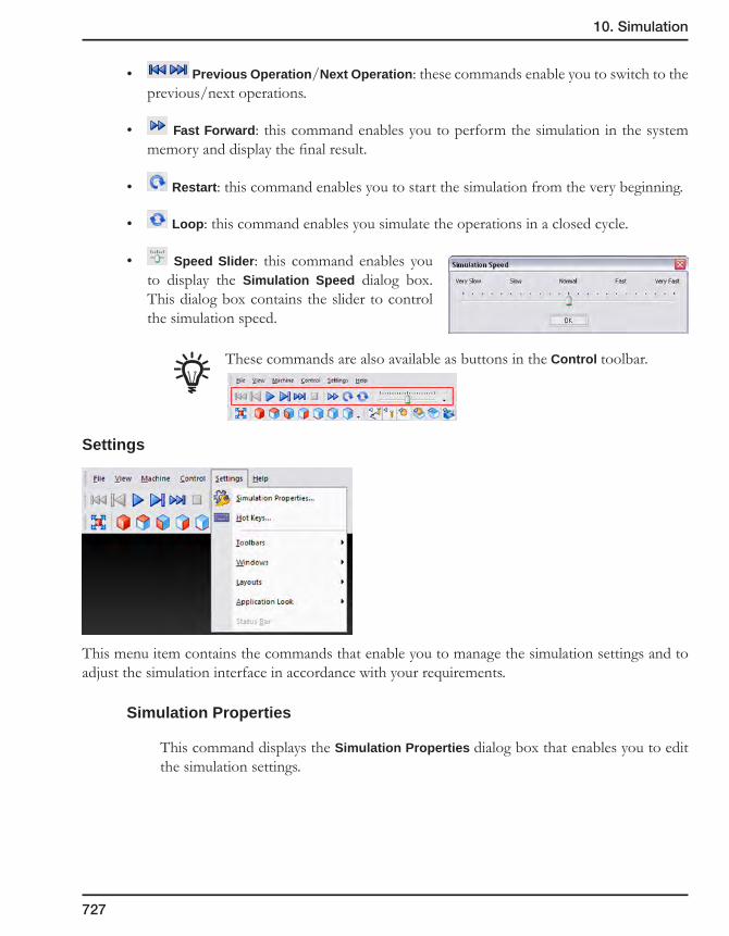
10. Simulation
727
• Previous Operation/Next Operation: these commands enable you to switch to the previous/next operations.
• Fast Forward: this command enables you to perform the simulation in the system memory and display the final result.
• Restart: this command enables you to start the simulation from the very beginning.
• Loop: this command enables you simulate the operations in a closed cycle.
• Speed Slider: this command enables you to display the Simulation Speed dialog box. This dialog box contains the slider to control the simulation speed.
These commands are also available as buttons in the Control toolbar.
Settings
This menu item contains the commands that enable you to manage the simulation settings and to adjust the simulation interface in accordance with your requirements.
Simulation Properties
This command displays the Simulation Properties dialog box that enables you to edit the simulation settings.

728
This dialog box contains the following sets of parameters for managing the Machine simulation settings:
Simulation Process
This tab contains options that affect the simulation when it is running.
The Stop conditions section enables you to stop the machining in the following cases:
• On tool change: whenever the tool changes;
• After ... moves: after a certain number of moves;
• Height relative to workpiece greater than ...: when the tool exceeds a certain threshold above the workpiece;
• At operation ... block ID ...: in a certain operation, in a certain move number. When the required operation name is chosen from the list, the total number of moves of this operation is automatically displayed in the Block ID edit box; this number can be edited. The move numbers are displayed in the Pos column of the Move List window.
The Notification section enables you to turn on the display of notifications in case of the following events reported:
• GeometricalCollision: collision between tool and machine geometry;
• MaterialCollision: collision between tool and workpiece;
• AxisLimitsOverrun:when one of the moving parts of the CNC-machine exceeds a limit defined in the CNC-machine definition;
• AxisValueMismatch:when wrong data is detected, e.g. wrong tool dimensions.

10. Simulation
729
The Miscellaneous section contains the Enable geometry collision checking when CutSim is used check box that activates the collision checking on the geometry in the material removal mode.
The Simulation section contains the summary of the simulation data.
Graphics and Background
This tab contains options for setting the background color of the simulation window, for display of Coordinate System and ruler, and the slider to control the visualization speed.
Tool Path Backplot
This tab contains parameters of tool path visualization.
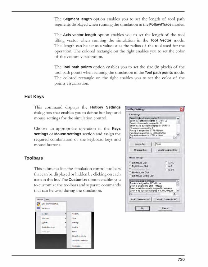
730
The Segment length option enables you to set the length of tool path segments displayed when running the simulation in the Follow/Trace modes.
The Axis vector length option enables you to set the length of the tool tilting vector when running the simulation in the Tool Vector mode. This length can be set as a value or as the radius of the tool used for the operation. The colored rectangle on the right enables you to set the color of the vectors visualization.
The Tool path points option enables you to set the size (in pixels) of the tool path points when running the simulation in the Tool path points mode. The colored rectangle on the right enables you to set the color of the points visualization.
Hot Keys
This command displays the HotKey Settings dialog box that enables you to define hot keys and mouse settings for the simulation control.
Choose an appropriate operation in the Keys settings or Mouse settings section and assign the required combination of the keyboard keys and mouse buttons.
Toolbars
This submenu lists the simulation control toolbars that can be displayed or hidden by clicking on each item in this list. The Customize option enables you to customize the toolbars and separate commands that can be used during the simulation.

10. Simulation
731
Windows
This submenu lists the simulation windows and tabs that enable you to define and control the CNC-machine and other data used for the simulation. These windows are displayed in tab view to the right from the graphic area (the Report, Machine and Analysis tabs and the Move List window) or at the bottom of the main SolidWorks window (the Progress bar and the Axis Control window).
Layouts
This submenu lists the simulation window layout options.
The Reset to default option resets the window layout to default.
The All Windows option displays all windows and tabs listed in the Windows submenu.
The No Windows option hides all windows and tabs listed in the Windows submenu. Only the graphic area is displayed.
The Save to file option enables you to save the current layout scheme as a *.layout file in the machine definition folder.
The Load from file option enables you to load a previously saved layout file.
Application Look
This submenu enables you to adapt the machine simulation interface to the color schemes of commonly used applications such as MS Office, Windows XP, etc.
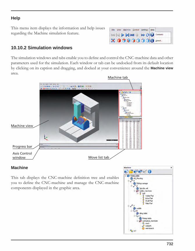
732
Help
This menu item displays the information and help issues regarding the Machine simulation feature.
10.10.2 Simulation windows
The simulation windows and tabs enable you to define and control the CNC-machine data and other parameters used for the simulation. Each window or tab can be undocked from its default location by clicking on its caption and dragging, and docked at your convenience around the Machine view area.
Machine
This tab displays the CNC-machine definition tree and enables you to define the CNC-machine and manage the CNC-machine components displayed in the graphic area.
Machine view
Axis Controlwindow
Progress bar
Move list tab
Machine tab

10. Simulation
733
The buttons in the tab toolbar enable you to manage existing machine definitions and add new ones.
• New Machine: this button enables you to create a new machine definition.
• Open Machine File: this button enables you to load a different existing machine.
• Save Machine: this button enables you to save the edited machine definition.
• Save Machine As: this button enables you to save the edited machine definition under a different name and/or in a different folder.
• Edit Machine: this button enables you to edit the current machine definition by right-clicking on an element to add/erase tree elements or display the machine properties.
• Info: this button toggles the display of the information about the listed machine components.
The CNC-machine definition tree displays all components of the CNC-machine used for the machining of the current CAM-part. The tree displays all the structure of the CNC-machine and the relation between all the CNC-machine components.
In the simulation mode, SolidCAM enables you to control the visual properties of the CNC-machine components using the right-click menu available on each component.
• Properties
The Appearance dialog box is displayed. The Visible check box enables you to control the visibility of the chosen component of the CNC-machine.
• Show/Hide
This option enables you to show/hide the chosen component of the CNC-machine.
• Transparent/Opaque
This option enables you to control the transparency of the chosen component of the CNC-machine.
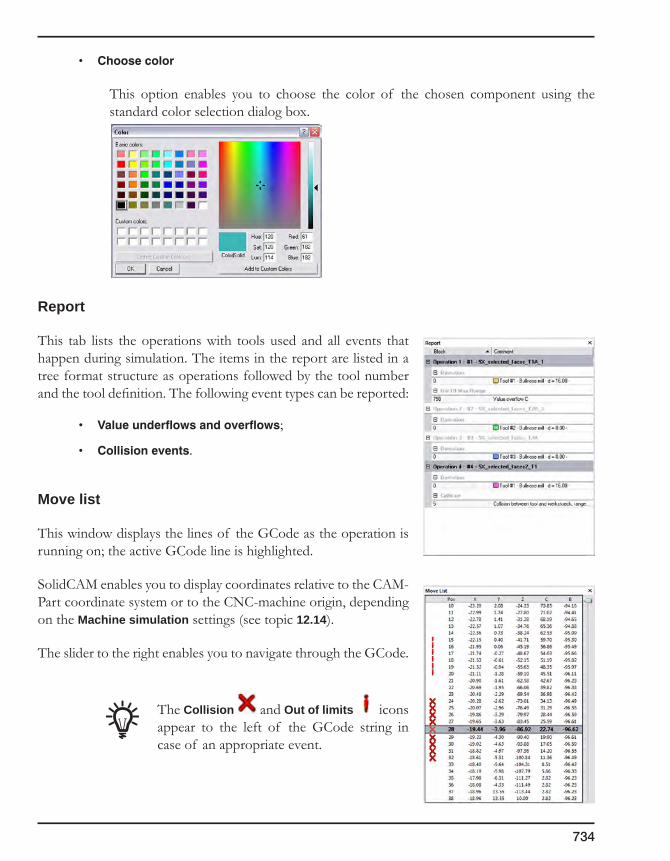
734
• Choosecolor
This option enables you to choose the color of the chosen component using the standard color selection dialog box.
Report
This tab lists the operations with tools used and all events that happen during simulation. The items in the report are listed in a tree format structure as operations followed by the tool number and the tool definition. The following event types can be reported:
• Valueunderflowsandoverflows;
• Collisionevents.
Move list
This window displays the lines of the GCode as the operation is running on; the active GCode line is highlighted.
SolidCAM enables you to display coordinates relative to the CAM-Part coordinate system or to the CNC-machine origin, depending on the Machine simulation settings (see topic 12.14).
The slider to the right enables you to navigate through the GCode.
The Collision and Out of limits icons appear to the left of the GCode string in case of an appropriate event.

10. Simulation
735
Axis Control
This window enables you to control the tool location manually using the axis sliders. It displays the current coordinates of the CNC-machine. Each axis has a control slider that enables you to perform manual movements within the specified limits.
The manual axis control cannot be used when the simulation is in progress. Stop the simulation to enable it.
Right-clicking on the coordinate sliders displays the Change slider position dialog box that enables you to enter the exact value for the current coordinate.
Progress
The Progress bar shows the advance of the simulation process. It consists of a slider that moves as the simulation is running on and a colored stripe that represents different tools by different colors. The colors of the tools are also displayed in the Report tab.
Analysis
This tab contains color representation of various elements of the simulation to facilitate the visualization. Choose an element from the list to display its analysis in colors.
You can change the color for each item by double-clicking on the corresponding rectangle and choose the desired color from the displayed Windows-style Color dialog box. Click on the
Refresh button in order for the change to take effect.

736
• Toolnumber
When you choose this element from the list, the table below displays the tool path color scheme according to the tools used in part operations. The tools are numbered in the corresponding column and represented by rectangles of different colors in the leftmost column.
• Operationnumber
When you choose this element from the list, the table below displays the tool path color scheme according to the part operations. The operations are numbered in the corresponding column and represented by rectangles of different colors in the leftmost column.

10. Simulation
737
• Toolpathsequence
When you choose this element from the list, the tool path is represented in a gradient color scale according to the progress of machining. This scale enables you to easily identify the start point and the end point of the machining, the cutting method (e.g. Zigzag or One way), the cut order (e.g. from outside to inside), and other machining parameters.
• Baxisvaluescale/Caxisvaluescale
When you choose this element from the list, the tool path is represented in a gradient color scale according to tilting angles of the machine rotation axis. This scale enables you to identify the rotation axis angle range used in the operation, the rotation angle used for machining of specific areas, and limit overruns that occur during the simulation. The angle range values are displayed in the corresponding columns of the table.
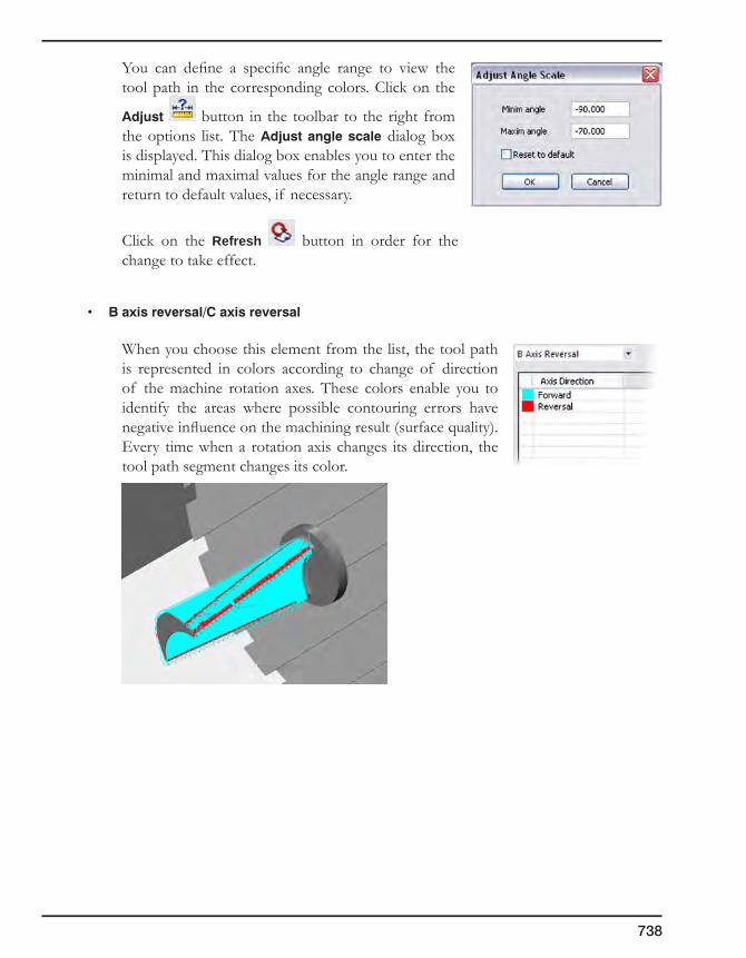
738
You can define a specific angle range to view the tool path in the corresponding colors. Click on the
Adjust button in the toolbar to the right from the options list. The Adjustanglescale dialog box is displayed. This dialog box enables you to enter the minimal and maximal values for the angle range and return to default values, if necessary.
Click on the Refresh button in order for the change to take effect.
• Baxisreversal/Caxisreversal
When you choose this element from the list, the tool path is represented in colors according to change of direction of the machine rotation axes. These colors enable you to identify the areas where possible contouring errors have negative influence on the machining result (surface quality). Every time when a rotation axis changes its direction, the tool path segment changes its color.

10. Simulation
739
• Baxisvaluechange/Caxisvaluechange
When you choose this element from the list, the tool path is represented in a gradient color scale according to change of tilting angles of the machine rotation axis. This scale enables you to identify the rotation speed range used in the operation, the rotation speed used for machining of specific areas and determine the areas where machine speed limits are reached.
You can define a specific angle range to view the tool path in the corresponding colors
by click on the Adjust button and entering the values into the Adjustanglescale
dialog box. Click on the Refresh button in order for the change to take effect.
• Linearaxisreversal
When you choose this element from the list, the tool path is represented in colors according to change of direction of the machine linear axes. Every time when a linear axis changes its direction, the tool path segment changes its color.

740
You can define a threshold angle value for the axis reversal to view the tool path in the corresponding colors by clicking on the Adjust
button and entering the values into the Linear axis threshold angle dialog box.
Click on the Refresh button in order for the change to take effect.
• Orientationchange
When you choose this element from the list, the tool path is represented in a gradient color scale according to change of orientation of the machine rotation axes. This scale enables you to identify the rotation speed range used in the operation, the rotation speed used for machining of specific areas and determine the areas where machine speed limits are reached.
Toolbar buttons
• Refresh: this button enables you to update the simulation when changes have been made in the analysis settings.
• Add: this button enables you to add values into the table.
• Remove: this button enables you to remove selected values from the table.
• Adjust: this button enables you to set limitations for specific parameters to display the tool path in different colors according to the defined settings.
• Autoadjust: when you click on this button, the system automatically sets the parameter ranges for the defined settings.
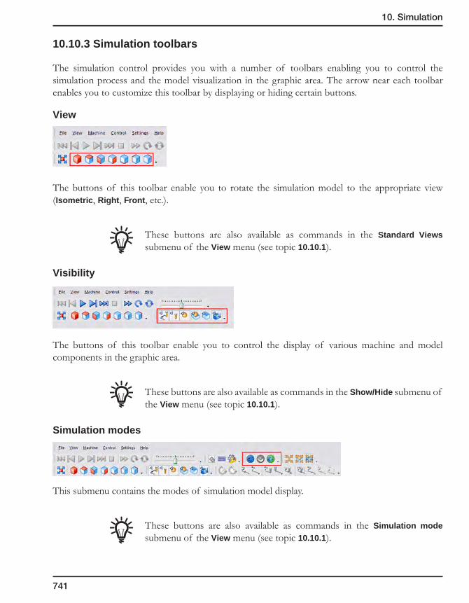
10. Simulation
741
10.10.3 Simulation toolbars
The simulation control provides you with a number of toolbars enabling you to control the simulation process and the model visualization in the graphic area. The arrow near each toolbar enables you to customize this toolbar by displaying or hiding certain buttons.
View
The buttons of this toolbar enable you to rotate the simulation model to the appropriate view (Isometric, Right, Front, etc.).
These buttons are also available as commands in the Standard Views submenu of the View menu (see topic 10.10.1).
Visibility
The buttons of this toolbar enable you to control the display of various machine and model components in the graphic area.
These buttons are also available as commands in the Show/Hide submenu of the View menu (see topic 10.10.1).
Simulation modes
This submenu contains the modes of simulation model display.
These buttons are also available as commands in the Simulation mode submenu of the View menu (see topic 10.10.1).

742
Focus
The buttons of this toolbar enable you to directly zoom and observe elements such as tool, workpiece and machine in stationary position.
These buttons are also available as commands in the Focus submenu of the View menu (see topic 10.10.1).
Tool path rendering
The buttons of this toolbar enable you to choose the mode of tool path display.
These buttons are also available as commands in the Focus submenu of the View menu (see topic 10.10.1).
Control
The buttons of this toolbar enable you to control the progress of the simulation.
These buttons are also available as commands in the Control menu (see topic 10.10.1).
Settings
The buttons of this toolbar enable you to manage the simulation settings and to adjust the simulation interface in accordance with your requirements.

10. Simulation
743
• The Create Presentation button enables you to create a self-extracting executable file containing the current CNC-machine and NC file (see topic 10.10.1).
• The Hot Keys button displays the HotKey Settings dialog box that enables you to define hot keys and mouse settings for the simulation control (see topic 10.10.1).
• The Simulation Properties button displays the Simulation Properties dialog box that enables you to edit the simulation settings (see topic 10.10.1).
10.10.4 CNC-machine definition parameters
SolidCAM enables you to define a number of CNC-machine parameters in the MAC file. These parameters enable you to take into account peculiar properties of the CNC-machine. These parameters are used on the different stages of the tool path calculations.
The following parameters must be defined in the MAC file:
CNC-machine kinematic type
The kinematic_type parameter enables you to define the type of kinematics of the CNC-machine. The following types are supported by SolidCAM according to the rotational axes location on the CNC-machine:
• Head-Head
In this type of CNC-machines, both rotational axes are mounted on the head of the CNC-machine.
Example:
kinematic_type = HEAD_HEAD
Rotation axes
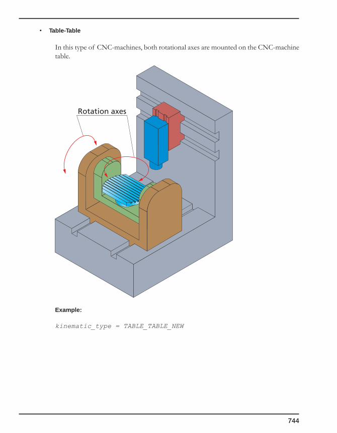
744
• Table-Table
In this type of CNC-machines, both rotational axes are mounted on the CNC-machine table.
Example:
kinematic_type = TABLE_TABLE_NEW
Rotation axes
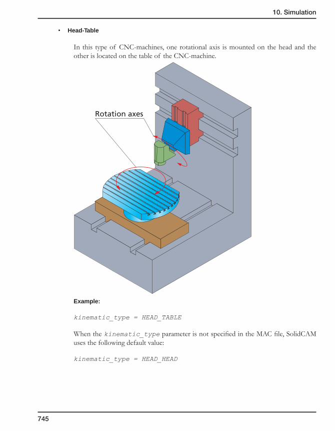
10. Simulation
745
• Head-Table
In this type of CNC-machines, one rotational axis is mounted on the head and the other is located on the table of the CNC-machine.
Example:
kinematic_type = HEAD_TABLE
When the kinematic_type parameter is not specified in the MAC file, SolidCAM uses the following default value:
kinematic_type = HEAD_HEAD
Rotation axes
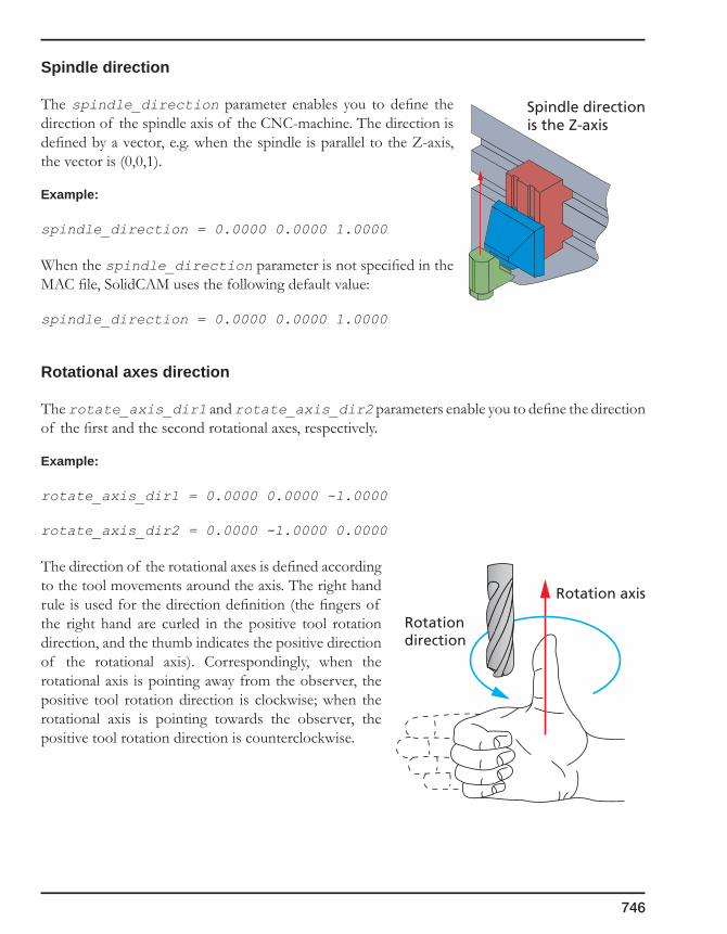
746
Spindle direction
The spindle_direction parameter enables you to define the direction of the spindle axis of the CNC-machine. The direction is defined by a vector, e.g. when the spindle is parallel to the Z-axis, the vector is (0,0,1).
Example:
spindle_direction = 0.0000 0.0000 1.0000
When the spindle_direction parameter is not specified in the MAC file, SolidCAM uses the following default value:
spindle_direction = 0.0000 0.0000 1.0000
Rotational axes direction
The rotate_axis_dir1 and rotate_axis_dir2 parameters enable you to define the direction of the first and the second rotational axes, respectively.
Example:
rotate_axis_dir1 = 0.0000 0.0000 -1.0000
rotate_axis_dir2 = 0.0000 -1.0000 0.0000
The direction of the rotational axes is defined according to the tool movements around the axis. The right hand rule is used for the direction definition (the fingers of the right hand are curled in the positive tool rotation direction, and the thumb indicates the positive direction of the rotational axis). Correspondingly, when the rotational axis is pointing away from the observer, the positive tool rotation direction is clockwise; when the rotational axis is pointing towards the observer, the positive tool rotation direction is counterclockwise.
Spindle directionis the Z-axis
Rotation axis
Rotationdirection
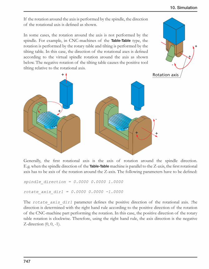
10. Simulation
747
If the rotation around the axis is performed by the spindle, the direction of the rotational axis is defined as shown.
In some cases, the rotation around the axis is not performed by the spindle. For example, in CNC-machines of the Table-Table type, the rotation is performed by the rotary table and tilting is performed by the tilting table. In this case, the direction of the rotational axes is defined according to the virtual spindle rotation around the axis as shown below. The negative rotation of the tilting table causes the positive tool tilting relative to the rotational axis.
Generally, the first rotational axis is the axis of rotation around the spindle direction. E.g. when the spindle direction of the Table-Table machine is parallel to the Z-axis, the first rotational axis has to be axis of the rotation around the Z-axis. The following parameters have to be defined:
spindle_direction = 0.0000 0.0000 1.0000
rotate_axis_dir1 = 0.0000 0.0000 -1.0000
The rotate_axis_dir1 parameter defines the positive direction of the rotational axis. The direction is determined with the right hand rule according to the positive direction of the rotation of the CNC-machine part performing the rotation. In this case, the positive direction of the rotary table rotation is clockwise. Therefore, using the right hand rule, the axis direction is the negative Z-direction (0, 0, -1).
+
+
+ +
-
-
+
+
-
Rotation axis

748
The first and the second rotational axis depend on the CNC-machine kinematic type:
• Table-Table
In this case, the first rotational axis performing the rotation around the spindle axis is mounted on the second rotational axis. The second rotational axis is mounted on the CNC-machine table.
• Head-Table
In this case, the first rotational axis performing the rotation around the spindle axis is mounted on the table. The second rotational axis is mounted on the head of the CNC-machine.
First rotation axisSecond rotation axis
Spindle direction
First rotation axis
Second rotation axis
Spindle direction

10. Simulation
749
• Head-Head
In this case, the first rotational axis performing the rotation around the spindle axis is mounted on the CNC-machine head. The second rotational axis is mounted on the first rotational axis.
When the rotate_axis_dir1 and rotate_axis_dir2 parameters are not specified in the MAC file, SolidCAM uses the following default values:
rotate_axis_dir1 = 0.0000 0.0000 -1.0000
rotate_axis_dir2 = 0.0000 -1.0000 0.0000
Rotational axes names
The first_rot_axis_name and second_rot_axis_name parameters enable you to define the names of the rotational axes that will be used in the Machine simulation.
Example:
first_rot_axis_name = C
second_rot_axis_name = B
When the first_rot_axis_name and second_rot_axis_name parameters are not specified in the MAC file, SolidCAM uses the following default values:
first_rot_axis_name = C
second_rot_axis_name = B
First rotation axis Second rotation axis
Spindle direction
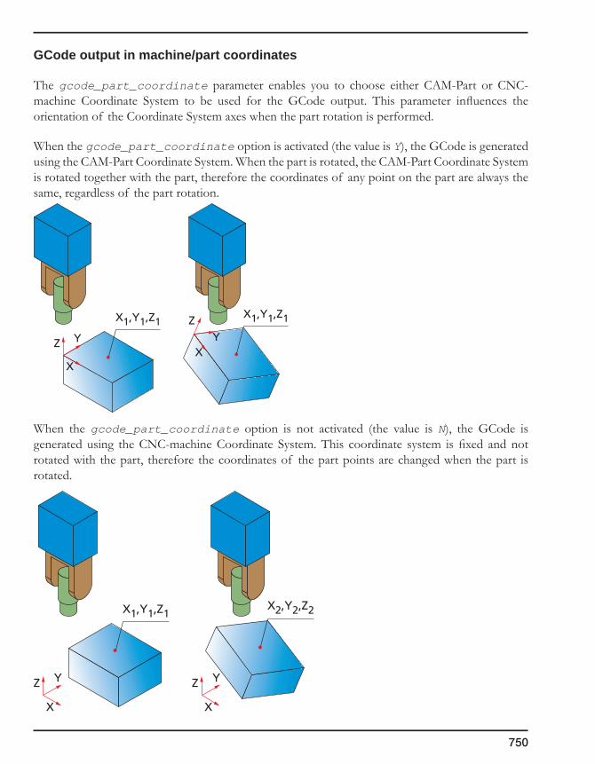
750
GCode output in machine/part coordinates
The gcode_part_coordinate parameter enables you to choose either CAM-Part or CNC-machine Coordinate System to be used for the GCode output. This parameter influences the orientation of the Coordinate System axes when the part rotation is performed.
When the gcode_part_coordinate option is activated (the value is Y), the GCode is generated using the CAM-Part Coordinate System. When the part is rotated, the CAM-Part Coordinate System is rotated together with the part, therefore the coordinates of any point on the part are always the same, regardless of the part rotation.
When the gcode_part_coordinate option is not activated (the value is N), the GCode is generated using the CNC-machine Coordinate System. This coordinate system is fixed and not rotated with the part, therefore the coordinates of the part points are changed when the part is rotated.
X
YZ
X
YZ
X1,Y1,Z1X2,Y2,Z2
XX
Y YZ
ZX1,Y1,Z1X1,Y1,Z1

10. Simulation
751
Example:
gcode_part_coordinate = Y
When the gcode_part_coordinate parameter is not specified in the MAC file, SolidCAM uses the following default value:
gcode_part_coordinate = N
Base points of rotational axes
Using the rot_axis_base_pnt1 and rot_axis_base_pnt2 variables, SolidCAM enables you to define the base points of the first and the second rotational axes. The base points define the location of the rotational axes relative to the CNC-machine origin.
Example:
rot_axis_base_pnt1 = 0.0000 0.0000 0.0000, 0.0000 0.0000 0.0000
rot_axis_base_pnt2 = 0.0000 0.0000 -254.0000, 0.0000 0.0000 -10.0000
The first three numbers define the XYZ location of the base point for Metric settings; the last three numbers define the XYZ location of the base point for Inch settings. The Metric and Inch settings are divided by comma
Generally, for Table-Table and Head-Table CNC-machines, the origin point is located in the intersection of the first rotational axis and the top face of the table. In this case, the location of the base point of the first rotational axis is (0,0,0).
First rotationaxis
Second rotationaxis
Origin
X
YZ
First rotationaxis
Z-value of therot_axis_base_pnt2parameter
Second rotationaxis
Origin
X
YZ
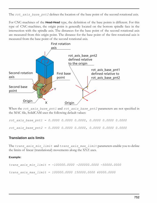
752
The rot_axis_base_pnt2 defines the location of the base point of the second rotational axis.
For CNC-machines of the Head-Head type, the definition of the base points is different. For this type of CNC-machines, the origin point is generally located on the bottom spindle face in the intersection with the spindle axis. The distances for the base point of the second rotational axis are measured from this origin point. The distance for the base point of the first rotational axis is measured from the base point of the second rotational axis.
When the rot_axis_base_pnt1 and rot_axis_base_pnt2 parameters are not specified in the MAC file, SolidCAM uses the following default values:
rot_axis_base_pnt1 = 0.0000 0.0000 0.0000, 0.0000 0.0000 0.0000
rot_axis_base_pnt2 = 0.0000 0.0000 0.0000, 0.0000 0.0000 0.0000
Translation axis limits
The trans_axis_min_limit and trans_axis_max_limit parameters enable you to define the limits of linear (translational) movements along the XYZ axes.
Example:
trans_axis_min_limit = -100000.0000 -200000.0000 -50000.0000
trans_axis_max_limit = 100000.0000 150000.0000 60000.0000
First rotationaxis
Second rotationaxis
Second basepoint
First basepoint
rot_axis_base_pnt1defined relative to rot_axis_base_pnt2
rot_axis_base_pnt2defined relative to the origin
OriginOriginX
Y
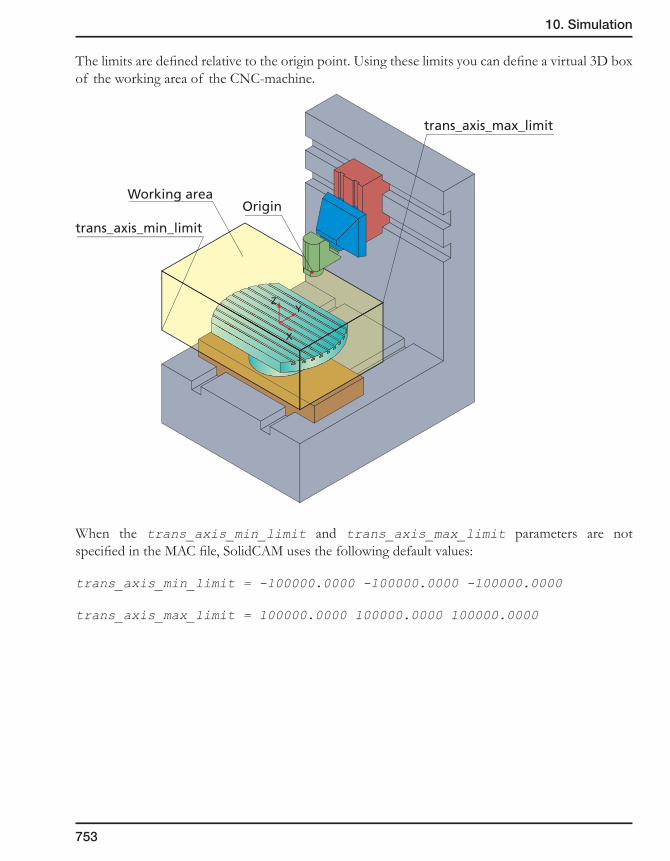
10. Simulation
753
The limits are defined relative to the origin point. Using these limits you can define a virtual 3D box of the working area of the CNC-machine.
When the trans_axis_min_limit and trans_axis_max_limit parameters are not specified in the MAC file, SolidCAM uses the following default values:
trans_axis_min_limit = -100000.0000 -100000.0000 -100000.0000
trans_axis_max_limit = 100000.0000 100000.0000 100000.0000
OriginWorking area
trans_axis_min_limit
trans_axis_max_limit
X
ZY

754
Rotational axis limits
The rot_axis_min_limit0 and rot_axis_max_limit0 parameters enable you to limit the rotation around the first rotational axis. The rot_axis_min_limit1 and rot_axis_max_limit1 parameters enable you to limit the rotation around the second rotational axis. The parameter value defines the limit rotation angle in degrees.
Example:
rot_axis_min_limit0 = -210.0000
rot_axis_min_limit1 = -30.0000
rot_axis_max_limit0 = 210.0000
rot_axis_max_limit1 = 130.0000
When these parameters are not specified in the MAC file, SolidCAM uses the following default values:
rot_axis_min_limit0 = -100000.0000
rot_axis_min_limit1 = -100000.0000
rot_axis_max_limit0 = 100000.0000
rot_axis_max_limit1 = -100000.0000
First rotationaxis
Second rotationaxis
rot_axis_min_limit0
rot_axis_max_limit0
rot_axis_min_limit1
rot_axis_max_limit1
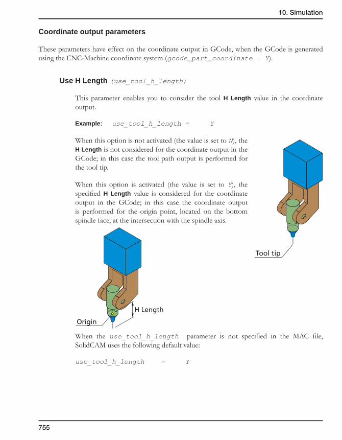
10. Simulation
755
Coordinate output parameters
These parameters have effect on the coordinate output in GCode, when the GCode is generated using the CNC-Machine coordinate system (gcode_part_coordinate = Y).
Use H Length (use_tool_h_length)
This parameter enables you to consider the tool H Length value in the coordinate output.
Example: use_tool_h_length = Y
When this option is not activated (the value is set to N), the H Length is not considered for the coordinate output in the GCode; in this case the tool path output is performed for the tool tip.
When this option is activated (the value is set to Y), the specified H Length value is considered for the coordinate output in the GCode; in this case the coordinate output is performed for the origin point, located on the bottom spindle face, at the intersection with the spindle axis.
When the use_tool_h_length parameter is not specified in the MAC file, SolidCAM uses the following default value:
use_tool_h_length = Y
Tool tip
Origin
H Length
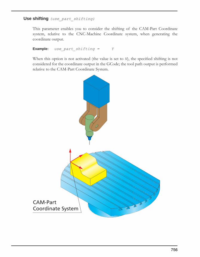
756
Use shifting (use_part_shifting)
This parameter enables you to consider the shifting of the CAM-Part Coordinate system, relative to the CNC-Machine Coordinate system, when generating the coordinate output.
Example: use_part_shifting = Y
When this option is not activated (the value is set to N), the specified shifting is not considered for the coordinate output in the GCode; the tool path output is performed relative to the CAM-Part Coordinate System.
CAM-PartCoordinate System
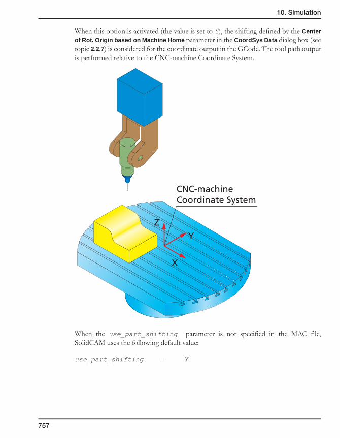
10. Simulation
757
When this option is activated (the value is set to Y), the shifting defined by the Center of Rot. Origin based on Machine Home parameter in the CoordSys Data dialog box (see topic 2.2.7) is considered for the coordinate output in the GCode. The tool path output is performed relative to the CNC-machine Coordinate System.
When the use_part_shifting parameter is not specified in the MAC file, SolidCAM uses the following default value:
use_part_shifting = Y
X
YZ
CNC-machineCoordinate System

758
Use base points of rotational axes
(use_rot_axis_base_point1, use_rot_axis_base_point2)
These parameters enable you to consider the base points of the rotational axes, when generating the coordinate output.
Example: use_rot_axis_base_point1 = Y
use_rot_axis_base_point2 = Y
When this option is not activated (the value is set to N), the base point coordinates are not considered in the calculation. In this case the tool path output is performed either for the tool tip (if the use_tool_h_length option is not activated) or for the origin point located on the bottom spindle face, at the intersection with the spindle axis (if the use_tool_h_length option is activated).
When the option is activated (the value is set to Y), the base point coordinates, defined by the rot_axis_base_pnt1/rot_axis_base_pnt2 parameters, are considered during the tool path calculation. In this case the tool path output is performed for the CNC-machine base points defined by the rot_axis_base_pnt1/rot_axis_base_pnt2 parameters.
When the use_rot_axis_base_pnt1/use_rot_axis_base_pnt2 parameters are not specified in the MAC file, SolidCAM uses the following default value:
use_rot_axis_base_point1 = Y
use_rot_axis_base_point2 = Y
Second basepoint
First basepoint
Origin
Tool tip

10. Simulation
759
Machine simulation
The machine_simulation parameter enables you to define the name of the CNC-machine model used for the Machine simulation.
Example:
machine_simulation = 5AxDMU50ev
The parameter value defines the folder where the appropriate model of the CNC-machine is stored. This folder is located in the Directory for Machine simulation definitions defined in the Machine simulation settings.
Consider that the Directory for Machine simulation definitions is the following:
C:\Program Files\SolidCAM2009\Tables\Metric\MachSim
In this case, the data of the CNC-machine 5AxDMU50ev mentioned in the example above is located in the following folder:
C:\Program Files\SolidCAM2009\Tables\Metric\MachSim\5AxDMU50ev
Example of CNC-machine definition
The following example is the section of a CNC-machine definition file. This section defines the parameters of the Okuma CNC-machine used for the Sim. 5 Axis machining and Machine simulation.
;Sim Five axis
kinematic_type = TABLE_TABLE
spindle_direction = 0.0000 0.0000 1.0000
rotate_axis_dir1 = 0.0000 0.0000 -1.0000
rotate_axis_dir2 = 0.0000 -1.0000 0.0000
rot_axis_base_pnt1 = 0.000 0.000 -15.398, 0.000 0.000 -6.000
rot_axis_base_pnt2 = 0.000 0.000 -100.353, 0.000 0.000 0.000
abs_machine_coord = N
first_rot_axis_name = C
second_rot_axis_name = B
rot_axis_min_limit0 = -100000.0000
rot_axis_min_limit1 = -20.0000
rot_axis_max_limit0 = 1000.0000
rot_axis_max_limit1 = 130.0000
machine_simulation = okuma12
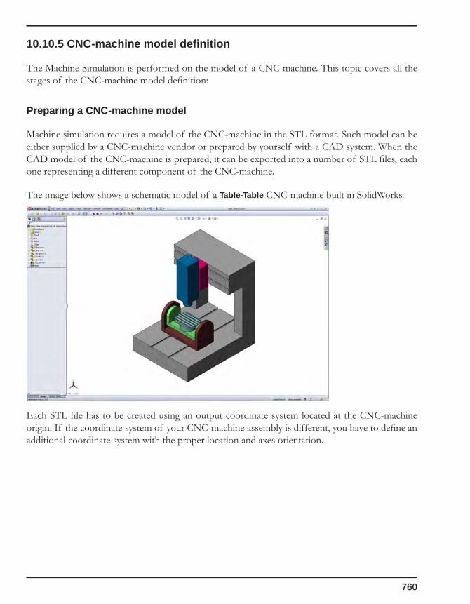
760
10.10.5 CNC-machine model definition
The Machine Simulation is performed on the model of a CNC-machine. This topic covers all the stages of the CNC-machine model definition:
Preparing a CNC-machine model
Machine simulation requires a model of the CNC-machine in the STL format. Such model can be either supplied by a CNC-machine vendor or prepared by yourself with a CAD system. When the CAD model of the CNC-machine is prepared, it can be exported into a number of STL files, each one representing a different component of the CNC-machine.
The image below shows a schematic model of a Table-Table CNC-machine built in SolidWorks.
Each STL file has to be created using an output coordinate system located at the CNC-machine origin. If the coordinate system of your CNC-machine assembly is different, you have to define an additional coordinate system with the proper location and axes orientation.

10. Simulation
761
In the case of the Table-Table machine shown above, you have to define a new coordinate system located in the intersection of the top face of the table and the rotational axis (CNC-machine origin).
When the coordinate system is defined, move all the components into their initial state (the components performing rotational axes movements have to be placed into their initial state at C=0, B=0; the components performing translational axes movements have to be placed at X=0, Y=0, Z=0).

762
After the coordinate system is defined and all the CNC-machine components are placed into their initial state, the CNC-machine model has to be exported into the STL format.
Click File, Save As. The Save As dialog box is displayed.
Choose the STL type for export of the model. Click on the Options button to define the additional parameters of export.
The Export Options dialog box is displayed.
This dialog box enables you to define a number of parameters affecting the STL export. See SolidWorks Help for detailed explanation on these parameters.
Adjust the STL Resolution parameters according to your needs.
In the Output coordinate system list, choose the defined Coordinate system for the STL export.

10. Simulation
763
Select the Do not translate STL output data to positive space check box. This option ensures that exported parts maintain their original position in global space, relative to the origin.
Confirm the Export Options dialog box with the OK button.
In the Save As dialog box, choose the location for the STL files and enter the name of the STL file for the CNC-machine assembly. Confirm the export with the Save button. Several separate STL files for all the CNC-machine assembly components are generated. All of these files will be used at the further stages of the CNC-machine definition.
A CNC-machine model consists of a number of components. It is recommended to try to define the CNC-machine with the minimum number of STL files. To reduce the number of STL files, you can put several components together in one sub-assembly that is exported into a single STL file; the criterion for putting several components into one STL file is the common movement of these components. When assembly components always move together, they can be combined into a sub-assembly. For example, the model of the spindle unit of a Table-Table CNC-machine consists of a number of components that have a common movement; according to the criterion above, all these spindle unit components can be combined into a sub-assembly.
Such sub-assemblies can be exported separately into STL files using the Save all components of an assembly in a single file option in the Export Options dialog box. This option creates a single STL file with all the components of a sub-assembly. Before the export of a sub-assembly, the new coordinate system has to be defined in the sub-assembly in the location of the CNC-machine origin.
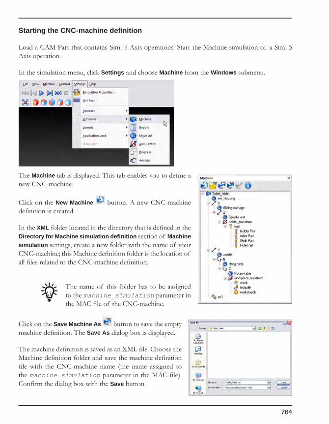
764
Starting the CNC-machine definition
Load a CAM-Part that contains Sim. 5 Axis operations. Start the Machine simulation of a Sim. 5 Axis operation.
In the simulation menu, click Settings and choose Machine from the Windows submenu.
The Machine tab is displayed. This tab enables you to define a new CNC-machine.
Click on the New Machine button. A new CNC-machine definition is created.
In the XML folder located in the directory that is defined in the Directory for Machine simulation definition section of Machine simulation settings, create a new folder with the name of your CNC-machine; this Machine definition folder is the location of all files related to the CNC-machine definition.
The name of this folder has to be assigned to the machine_simulation parameter in the MAC file of the CNC-machine.
Click on the Save Machine As button to save the empty machine definition. The Save As dialog box is displayed.
The machine definition is saved as an XML file. Choose the Machine definition folder and save the machine definition file with the CNC-machine name (the name assigned to the machine_simulation parameter in the MAC file). Confirm the dialog box with the Save button.
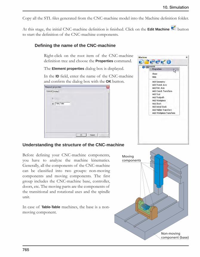
10. Simulation
765
Copy all the STL files generated from the CNC-machine model into the Machine definition folder.
At this stage, the initial CNC-machine definition is finished. Click on the Edit Machine button to start the definition of the CNC-machine components.
Defining the name of the CNC-machine
Right-click on the root item of the CNC-machine definition tree and choose the Properties command.
The Element properties dialog box is displayed.
In the ID field, enter the name of the CNC-machine and confirm the dialog box with the OK button.
Understanding the structure of the CNC-machine
Before defining your CNC-machine components, you have to analyze the machine kinematics. Generally, all the components of the CNC-machine can be classified into two groups: non-moving components and moving components. The first group includes the CNC-machine base, controller, doors, etc. The moving parts are the components of the transitional and rotational axes and the spindle unit.
In case of Table-Table machines, the base is a non-moving component.
Movingcomponents
Non-movingcomponent (base)

766
All the moving components can be classified according to the dependency of the movements. For example, in the Table-Table CNC-machine the rotary table that provides the rotation around the vertical axis (C-axis) is mounted on the tilting table. The tilting table that provides the rotation around the X-axis (B-axis), is mounted on the saddle. The saddle performs the X-axis movements. Movement of the saddle affects the location of the B-axis and C-axis (the tilting and rotary tables are moved). Movement of the tilting table (rotation around B-axis) affects the orientation of the C-axis (the rotary table is moved together with the tilting table), but does not affect the X-axis. The rotary table movement (rotation around C-axis) does not affect the B-axis and X-axis orientation.
Hierarchically, we can describe the structure of the rotary table, tilting table and saddle using “parents-children” relations. The saddle is the “parent” of the tilting table because the tilting table (“child”) is mounted on the saddle. Similarly, the tilting table is the “parent” of the rotary table because the rotary table is mounted on the tilting table.
Another separate set of the CNC-machine components provides the movements in the YZ-plane. The sliding carriage provides movements along the Y-axis, and the spindle unit performs the Z-axis movements. In this hierarchy the sliding carriage is a “parent” and the spindle unit is a “child”.
Rotary table
Tilting tableSaddle
Sliding carriage
Spindle unit

10. Simulation
767
The structure of a Head-Table CNC-machine can be described by two separate sets of components. The components of these sets are combined together according to the “parents-children” criterion.
The first set consists of the tilting head with the spindle unit (B-axis) mounted on the vertical saddle (Z-axis). The vertical saddle is mounted on the horizontal saddle (X-axis).
The second set consists of the rotary table (C-axis) mounted on the sliding carriage (Y-axis).
Tilting head
Vertical saddle
Horizontal saddle
Sliding carriage
Rotary table
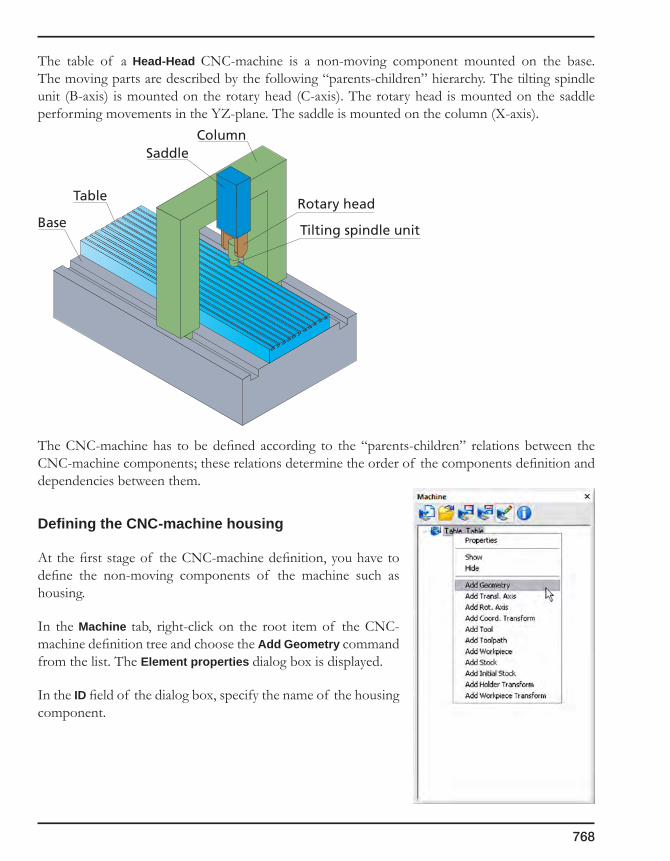
768
The table of a Head-Head CNC-machine is a non-moving component mounted on the base. The moving parts are described by the following “parents-children” hierarchy. The tilting spindle unit (B-axis) is mounted on the rotary head (C-axis). The rotary head is mounted on the saddle performing movements in the YZ-plane. The saddle is mounted on the column (X-axis).
The CNC-machine has to be defined according to the “parents-children” relations between the CNC-machine components; these relations determine the order of the components definition and dependencies between them.
Defining the CNC-machine housing
At the first stage of the CNC-machine definition, you have to define the non-moving components of the machine such as housing.
In the Machine tab, right-click on the root item of the CNC-machine definition tree and choose the Add Geometry command from the list. The Element properties dialog box is displayed.
In the ID field of the dialog box, specify the name of the housing component.
Table
Base
Column
Rotary head
Tilting spindle unit
Saddle

10. Simulation
769
When the mh_ prefix appears in the ID of a CNC-machine component, this component is considered as a housing part. The components defined with this prefix can be hidden during the simulation using the Show/Hide
machine housing button. In this case, the ID value is set to mh_Housing.
Click on the Browse button and choose the STL model of the housing located in the Machine definition folder.
Switch to the Display tab. This tab enables you to control the CNC-machine component name display in the CNC-machine definition tree.
The component ID is always displayed in the tree. SolidCAM enables you to optionally display the STL file name chosen for the specific component by selecting the File name check box.
Switch to the Appearance tab. This tab enables you to control over the visibility and the visual properties (color, transparency, reflectivity) of the component of the CNC-machine.

770
Choose the appropriate settings for the housing component and confirm the Element properties dialog box with the OK button.
The housing part is displayed in the graphic area and the housing component name is displayed in the CNC-machine definition tree.
Click on the button and save the machine definition in the previously created XML file.
All the additional non-moving components are defined in the same manner. When this stage is finished, you have to start the definition of the moving components of the CNC-machine.
Defining the translational axis
When all the non-moving components of the CNC-machine are defined, you have to define the moving components. Moving components have to be defined according to their “parents-children” dependencies. The order of the definition is the following: “parents” have to be defined before the “children”. In case of Table-Table machines, the first component to be defined is the saddle performing the Y-axis translational movements.

10. Simulation
771
Right-click on the CNC-machine name in the definition tree and choose the Add Transl. axis command from the menu.
The Element properties dialog box is displayed. Set the translational axis name in the ID field.
Use the following built-in ID names:
• For the X-axis (linear axis), the ID is X;
• For the Y-axis (linear axis), the ID is Y;
• For the Z-axis (linear axis), the ID is Z;
• For the A-axis (rotational axis), the ID is A;
• For the B-axis (rotational axis), the ID is B;
• For the C-axis (rotational axis), the ID is C.
Set Y for the axis ID.
Switch to the Display tab. This tab enables you to choose the information that will be displayed in the CNC-machine definition tree.
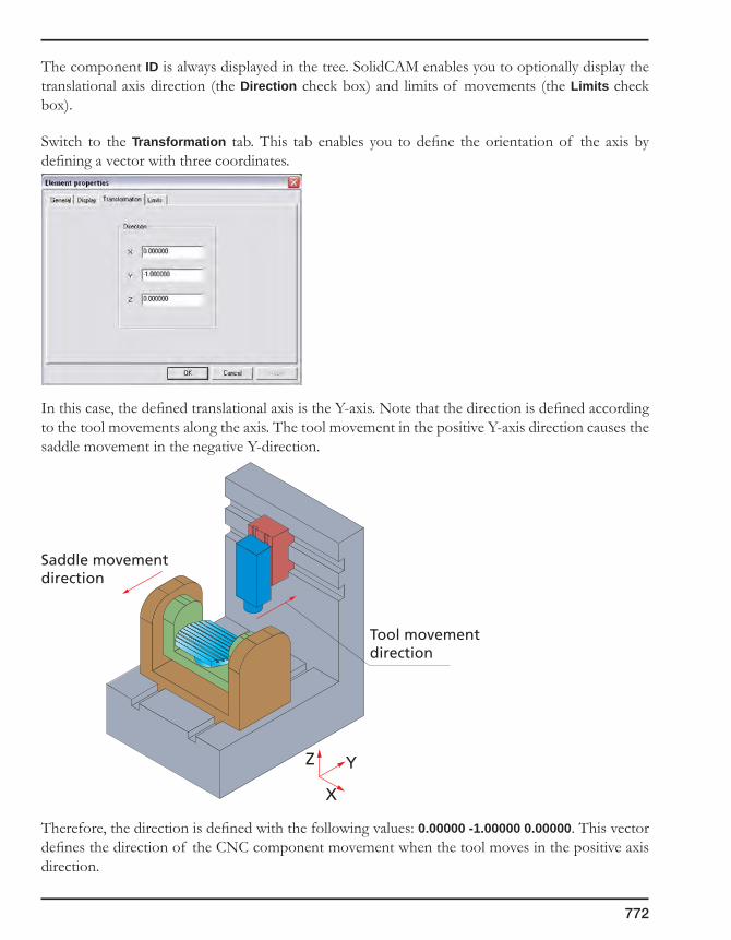
772
The component ID is always displayed in the tree. SolidCAM enables you to optionally display the translational axis direction (the Direction check box) and limits of movements (the Limits check box).
Switch to the Transformation tab. This tab enables you to define the orientation of the axis by defining a vector with three coordinates.
In this case, the defined translational axis is the Y-axis. Note that the direction is defined according to the tool movements along the axis. The tool movement in the positive Y-axis direction causes the saddle movement in the negative Y-direction.
Therefore, the direction is defined with the following values: 0.00000 -1.00000 0.00000. This vector defines the direction of the CNC component movement when the tool moves in the positive axis direction.
Saddle movementdirection
Tool movementdirection
X
YZ

10. Simulation
773
Switch to the Limits tab. This tab enables you to define the limit of the translational movements along the axis.
In this tab, you have to specify the Min Limit and Max Limit values. The movement of the saddle that performs the Y-axis movements is limited between this values. In this case, the Min Limit is -350 and Max Limit is 350.
The defined Min Limit and Max Limit values must be the same as those defined in the Y-coordinate of the trans_axis_min_limit and trans_axis_max_limit parameters specified in the MAC file of the CNC-machine.
When the limits are defined, click on the OK button to confirm the axis definition.
When the translational axis parameters are defined, specify the geometry of the part performing the translational movement along the axis. In this case, this part is the saddle.
In the CNC-machine definition tree, right-click on the just defined axis item and choose Add Geometry from the menu.
The Element properties dialog box is displayed.
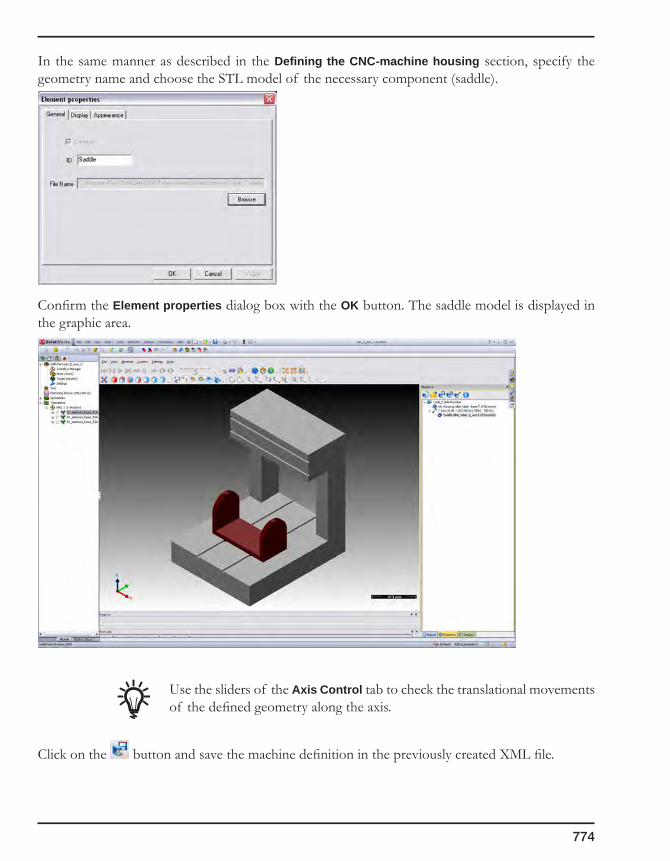
774
In the same manner as described in the Defining the CNC-machine housing section, specify the geometry name and choose the STL model of the necessary component (saddle).
Confirm the Element properties dialog box with the OK button. The saddle model is displayed in the graphic area.
Use the sliders of the Axis Control tab to check the translational movements of the defined geometry along the axis.
Click on the button and save the machine definition in the previously created XML file.

10. Simulation
775
Defining the rotational axis
Defining the tilting table
At this stage, you have to define the tilting table providing the B-axis rotation.
In the CNC-machine definition tree, right-click on the Y-axis item and choose the Add Rot. Axis command from the menu.
The Element properties dialog box is displayed. Define the ID of the rotational axis. Type B in the ID field.
Switch to the Transformation tab. This tab enables you to define the Direction of the rotational axis and the Center point. These parameters determine the location and orientation of the rotational axis.
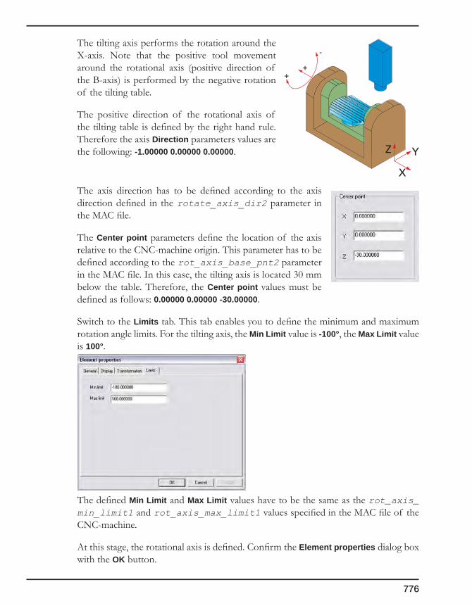
776
The tilting axis performs the rotation around the X-axis. Note that the positive tool movement around the rotational axis (positive direction of the B-axis) is performed by the negative rotation of the tilting table.
The positive direction of the rotational axis of the tilting table is defined by the right hand rule. Therefore the axis Direction parameters values are the following: -1.00000 0.00000 0.00000.
The axis direction has to be defined according to the axis direction defined in the rotate_axis_dir2 parameter in the MAC file.
The Center point parameters define the location of the axis relative to the CNC-machine origin. This parameter has to be defined according to the rot_axis_base_pnt2 parameter in the MAC file. In this case, the tilting axis is located 30 mm below the table. Therefore, the Center point values must be defined as follows: 0.00000 0.00000 -30.00000.
Switch to the Limits tab. This tab enables you to define the minimum and maximum rotation angle limits. For the tilting axis, the Min Limit value is -100°, the Max Limit value is 100°.
The defined Min Limit and Max Limit values have to be the same as the rot_axis_min_limit1 and rot_axis_max_limit1 values specified in the MAC file of the CNC-machine.
At this stage, the rotational axis is defined. Confirm the Element properties dialog box with the OK button.
++
-
X
YZ

10. Simulation
777
Define the geometry of the tilting table. In the CNC-machine definition tree, right-click on the just defined rotational axis item and choose the Add Geometry command from the menu.
The Elements properties dialog box is displayed. In the same manner as described in the Defining the CNC-machine housing section, set the ID for the tilting table geometry and choose the geometry from the STL file.
The tilting table geometry is displayed in the graphic area.
Use the sliders of the Axis Control tab to check the translational movements of the defined geometry along the axis.
Click on the button and save the machine definition in the previously created XML file.

778
Defining the rotary table
At this stage, you have to define the rotary table that provides the C-axis rotation.
In the CNC-machine definition tree, right-click on the B-axis item and choose the Add Rot. Axis command from the menu.
The Element properties dialog box is displayed. Define the ID of the rotational axis.
Type C in the ID field.
Switch to the Transformation tab.
The rotary axis performs the rotation around the Z-axis. Note that the positive tool rotation around the rotational axis (positive direction of the C-axis) is performed by the negative rotation of the rotary table; the positive direction of the rotational axis of the rotary table is defined by the right hand rule. Therefore the axis Direction parameters values are the following: 0.00000 0.00000 -1.00000.
The axis direction has to be defined according to the axis direction defined in the rotate_axis_dir1 parameter in the MAC file.
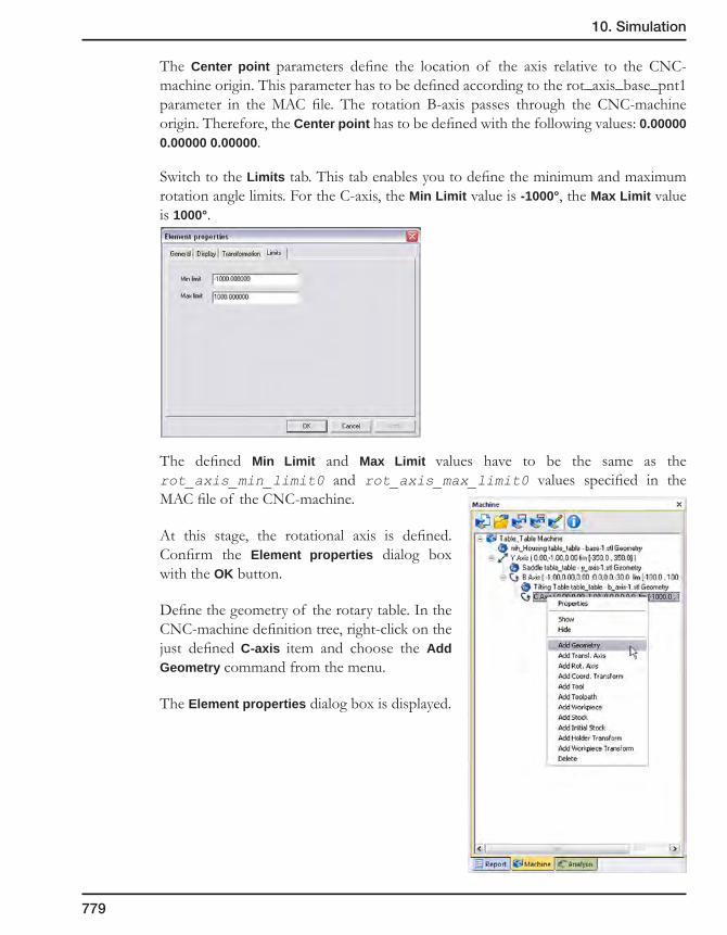
10. Simulation
779
The Center point parameters define the location of the axis relative to the CNC-machine origin. This parameter has to be defined according to the rot_axis_base_pnt1 parameter in the MAC file. The rotation B-axis passes through the CNC-machine origin. Therefore, the Center point has to be defined with the following values: 0.00000 0.00000 0.00000.
Switch to the Limits tab. This tab enables you to define the minimum and maximum rotation angle limits. For the C-axis, the Min Limit value is -1000°, the Max Limit value is 1000°.
The defined Min Limit and Max Limit values have to be the same as the rot_axis_min_limit0 and rot_axis_max_limit0 values specified in the MAC file of the CNC-machine.
At this stage, the rotational axis is defined. Confirm the Element properties dialog box with the OK button.
Define the geometry of the rotary table. In the CNC-machine definition tree, right-click on the just defined C-axis item and choose the Add Geometry command from the menu.
The Element properties dialog box is displayed.

780
In the same manner as explained in the Defining the CNC-machine housing section, set the ID for the rotary table geometry and choose the geometry from the STL file.
The rotary table geometry is displayed in the graphic area.
Use the sliders of the Axis Control tab to check the translational movements of the defined geometry along the axis.
Click on the button and save the machine definition in the previously created XML file.
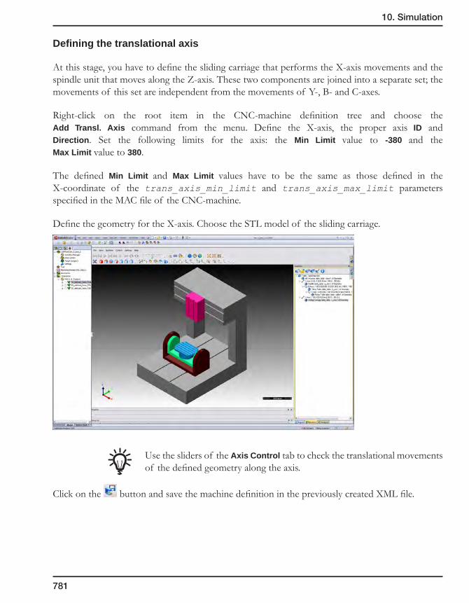
10. Simulation
781
Defining the translational axis
At this stage, you have to define the sliding carriage that performs the X-axis movements and the spindle unit that moves along the Z-axis. These two components are joined into a separate set; the movements of this set are independent from the movements of Y-, B- and C-axes.
Right-click on the root item in the CNC-machine definition tree and choose the Add Transl. Axis command from the menu. Define the X-axis, the proper axis ID and Direction. Set the following limits for the axis: the Min Limit value to -380 and the Max Limit value to 380.
The defined Min Limit and Max Limit values have to be the same as those defined in the X-coordinate of the trans_axis_min_limit and trans_axis_max_limit parameters specified in the MAC file of the CNC-machine.
Define the geometry for the X-axis. Choose the STL model of the sliding carriage.
Use the sliders of the Axis Control tab to check the translational movements of the defined geometry along the axis.
Click on the button and save the machine definition in the previously created XML file.

782
Define the Z-axis. Note that the Z-axis is a “child” of the X-axis. Define the proper axis ID and Direction. Set the following limits for the Z-axis: set the Min Limit value to 0 and the Max Limit value to 300.
The defined Min Limit and Max Limit values have to be the same as those defined in the Z-coordinate of the trans_axis_min_limit and trans_axis_max_limit parameters specified in the MAC file of the CNC-machine.
Define the geometry for the Z-axis. Choose the STL model of the spindle unit.
Use the sliders of the Axis Control tab to check the translational movements of the defined geometry along the axis.
Click on the button and save the machine definition in the previously created XML file.
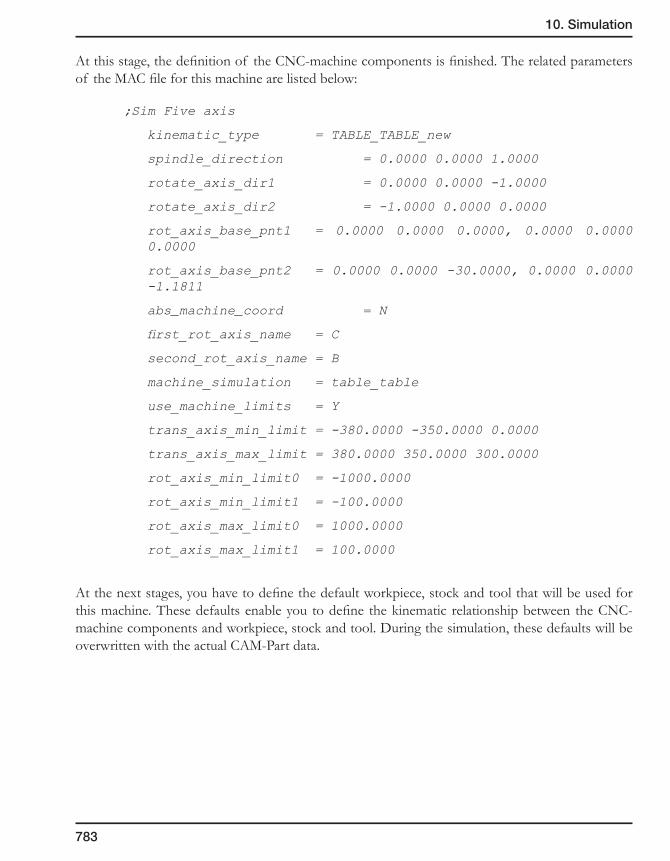
10. Simulation
783
At this stage, the definition of the CNC-machine components is finished. The related parameters of the MAC file for this machine are listed below:
;Sim Five axis
kinematic_type = TABLE_TABLE_new
spindle_direction = 0.0000 0.0000 1.0000
rotate_axis_dir1 = 0.0000 0.0000 -1.0000
rotate_axis_dir2 = -1.0000 0.0000 0.0000
rot_axis_base_pnt1 = 0.0000 0.0000 0.0000, 0.0000 0.0000 0.0000
rot_axis_base_pnt2 = 0.0000 0.0000 -30.0000, 0.0000 0.0000 -1.1811
abs_machine_coord = N
first_rot_axis_name = C
second_rot_axis_name = B
machine_simulation = table_table
use_machine_limits = Y
trans_axis_min_limit = -380.0000 -350.0000 0.0000
trans_axis_max_limit = 380.0000 350.0000 300.0000
rot_axis_min_limit0 = -1000.0000
rot_axis_min_limit1 = -100.0000
rot_axis_max_limit0 = 1000.0000
rot_axis_max_limit1 = 100.0000
At the next stages, you have to define the default workpiece, stock and tool that will be used for this machine. These defaults enable you to define the kinematic relationship between the CNC-machine components and workpiece, stock and tool. During the simulation, these defaults will be overwritten with the actual CAM-Part data.

784
Defining the workpiece
At this stage, you have to define the default workpiece and its kinematic relationship with the CNC-machine components.
The workpiece is located on the CNC-machine rotary table (C-axis). In the CNC-machine definition tree, right-click on the C-axis item and choose the Add Coord. Transform command from the menu. This command enables you to define the kinematic relationship between the workpiece and the CNC-machine components.
The Element properties dialog box is displayed. Define the ID of the workpiece. Use the built-in workpiece_transform name for the ID. This name is hard-coded in SolidCAM and cannot be changed.
Confirm the dialog box with the OK button. The appropriate item is displayed in the CNC-machine definition tree.
Now you have to define the default model of the workpiece. Right-click on the just added Transform item in the CNC-machine definition tree and choose the Add Workpiece command from the menu.
The Element properties dialog box is displayed.

10. Simulation
785
Set the ID of the workpiece geometry. Use the built-in werkstueck name for the ID. This name is hard-coded in SolidCAM and cannot be changed.
Confirm the dialog box with the OK button.
The workpiece geometry with the built-in name werkstueck is related to the werkstueck.stl file. In the process of the CNC-machine definition this file does not exist. It will be automatically created during the simulation. Every time during the simulation this file will be overwritten with the actual target model data.
Click on the button and save the machine definition in the previously created XML file.
Defining the stock
At this stage, you have to define the default stock and its kinematic relationship with the CNC-machine components.
Similar to the workpiece, the stock is located on the CNC-machine rotary table (C-axis). All the coordinate transformations are the same for the workpiece and the stock. Therefore, you do not need to define a separate coordinate transformation for the stock. Use the existing transformation of the workpiece.
In the CNC-machine definition tree, right-click on the workpiece_transform coordinate transformation item and choose the Add Stock command from the menu. This command enables you to define the geometry of the stock.
The Element properties dialog box is displayed.
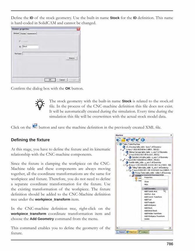
786
Define the ID of the stock geometry. Use the built-in name Stock for the ID definition. This name is hard-coded in SolidCAM and cannot be changed.
Confirm the dialog box with the OK button.
The stock geometry with the built-in name Stock is related to the stock.stl file. In the process of the CNC-machine definition this file does not exist. It will be automatically created during the simulation. Every time during the simulation this file will be overwritten with the actual stock model data.
Click on the button and save the machine definition in the previously created XML file.
Defining the fixture
At this stage, you have to define the fixture and its kinematic relationship with the CNC-machine components.
Since the fixture is clamping the workpiece on the CNC-Machine table and these components are always moving together, all the coordinate transformations are the same for workpiece and fixture. Therefore, you do not need to define a separate coordinate transformation for the fixture. Use the existing transformation of the workpiece. The fixture definition should be added to the CNC-Machine definition tree under the workpiece_transform item.
In the CNC-machine definition tree, right-click on the workpiece_transform coordinate transformation item and choose the Add Geometry command from the menu.
This command enables you to define the geometry of the fixture.
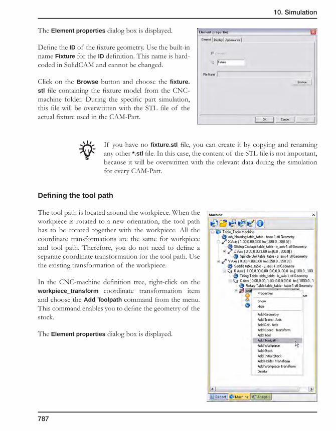
10. Simulation
787
The Element properties dialog box is displayed.
Define the ID of the fixture geometry. Use the built-in name Fixture for the ID definition. This name is hard-coded in SolidCAM and cannot be changed.
Click on the Browse button and choose the fixture.stl file containing the fixture model from the CNC-machine folder. During the specific part simulation, this file will be overwritten with the STL file of the actual fixture used in the CAM-Part.
If you have no fixture.stl file, you can create it by copying and renaming any other *.stl file. In this case, the content of the STL file is not important, because it will be overwritten with the relevant data during the simulation for every CAM-Part.
Defining the tool path
The tool path is located around the workpiece. When the workpiece is rotated to a new orientation, the tool path has to be rotated together with the workpiece. All the coordinate transformations are the same for workpiece and tool path. Therefore, you do not need to define a separate coordinate transformation for the tool path. Use the existing transformation of the workpiece.
In the CNC-machine definition tree, right-click on the workpiece_transform coordinate transformation item and choose the Add Toolpath command from the menu. This command enables you to define the geometry of the stock.
The Element properties dialog box is displayed.

788
Define the ID of the stock geometry. Use the built-in name Toolpath for the ID definition. This name is hard-coded in SolidCAM and cannot be changed.
Confirm the dialog box with the OK button.
The tool path geometry with the built-in name Toolpath is related to the toolpath.asc file. In the process of the CNC-machine definition this file does not exist. It will be automatically created during the simulation. Every time during the simulation this file will be overwritten with the actual tool path.
Click on the button and save the machine definition in the previously created XML file.
Defining the tool
At this stage, you have to define the default tool and its kinematic relationship with the CNC-machine components.
The tool with holder is mounted on the CNC-machine spindle unit (Z-axis). In the CNC-machine definition tree, right-click on the Z-axis item and choose the Add Coord. Transform command from the menu. This command enables you to define the kinematic relationship between the tool and the CNC-machine components.
The Element properties dialog box is displayed.
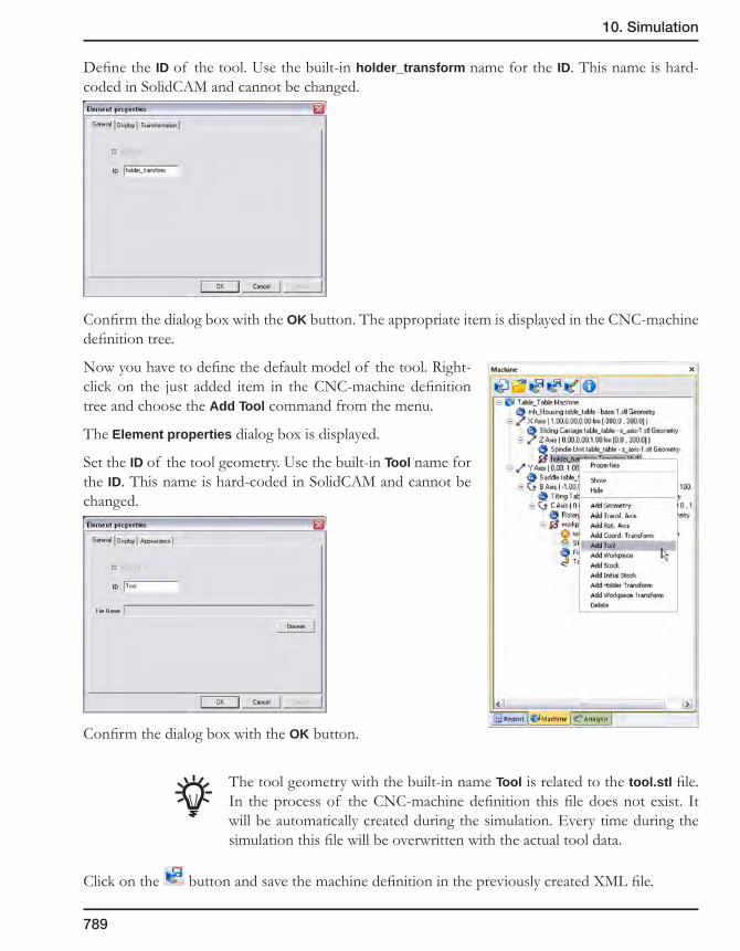
10. Simulation
789
Define the ID of the tool. Use the built-in holder_transform name for the ID. This name is hard-coded in SolidCAM and cannot be changed.
Confirm the dialog box with the OK button. The appropriate item is displayed in the CNC-machine definition tree.
Now you have to define the default model of the tool. Right-click on the just added item in the CNC-machine definition tree and choose the Add Tool command from the menu.
The Element properties dialog box is displayed.
Set the ID of the tool geometry. Use the built-in Tool name for the ID. This name is hard-coded in SolidCAM and cannot be changed.
Confirm the dialog box with the OK button.
The tool geometry with the built-in name Tool is related to the tool.stl file. In the process of the CNC-machine definition this file does not exist. It will be automatically created during the simulation. Every time during the simulation this file will be overwritten with the actual tool data.
Click on the button and save the machine definition in the previously created XML file.
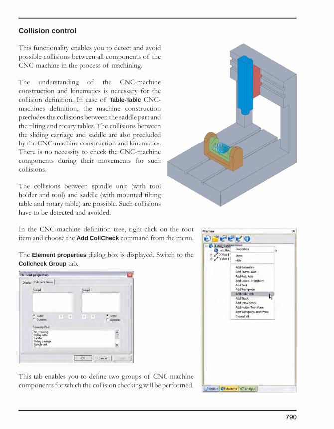
790
Collision control
This functionality enables you to detect and avoid possible collisions between all components of the CNC-machine in the process of machining.
The understanding of the CNC-machine construction and kinematics is necessary for the collision definition. In case of Table-Table CNC-machines definition, the machine construction precludes the collisions between the saddle part and the tilting and rotary tables. The collisions between the sliding carriage and saddle are also precluded by the CNC-machine construction and kinematics. There is no necessity to check the CNC-machine components during their movements for such collisions.
The collisions between spindle unit (with tool holder and tool) and saddle (with mounted tilting table and rotary table) are possible. Such collisions have to be detected and avoided.
In the CNC-machine definition tree, right-click on the root item and choose the Add CollCheck command from the menu.
The Element properties dialog box is displayed. Switch to the Collcheck Group tab.
This tab enables you to define two groups of CNC-machine components for which the collision checking will be performed.
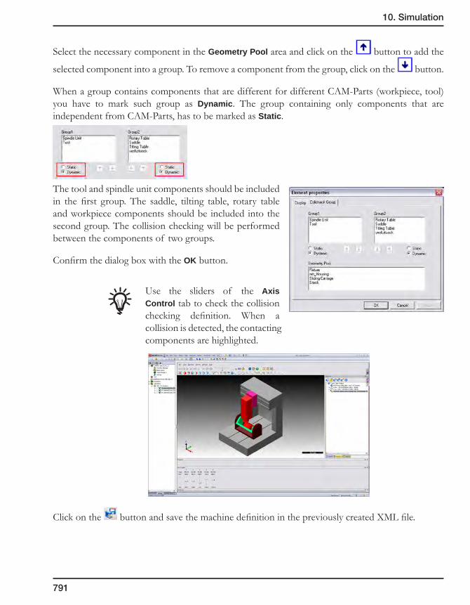
10. Simulation
791
Select the necessary component in the Geometry Pool area and click on the button to add the
selected component into a group. To remove a component from the group, click on the button.
When a group contains components that are different for different CAM-Parts (workpiece, tool) you have to mark such group as Dynamic. The group containing only components that are independent from CAM-Parts, has to be marked as Static.
The tool and spindle unit components should be included in the first group. The saddle, tilting table, rotary table and workpiece components should be included into the second group. The collision checking will be performed between the components of two groups.
Confirm the dialog box with the OK button.
Use the sliders of the Axis Control tab to check the collision checking definition. When a collision is detected, the contacting components are highlighted.
Click on the button and save the machine definition in the previously created XML file.
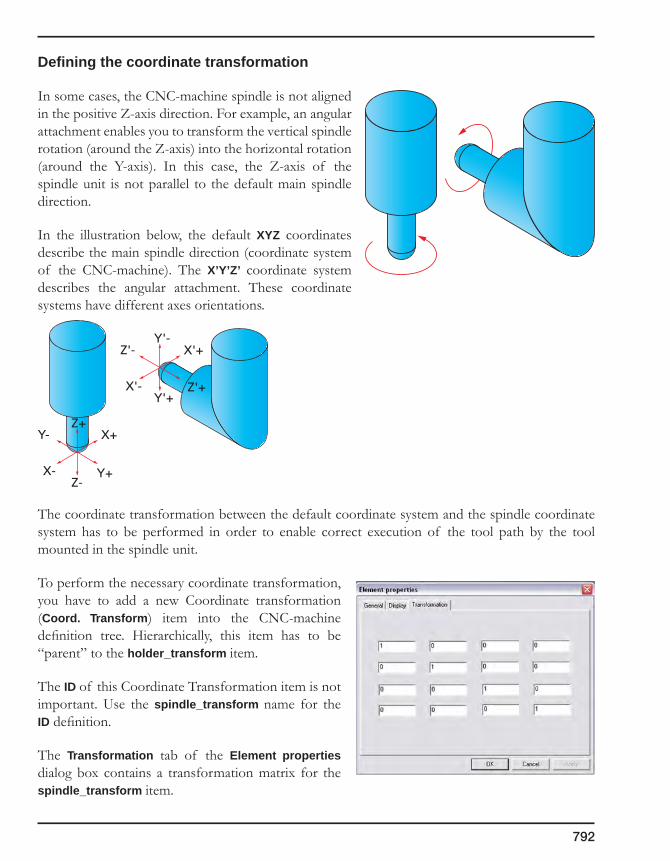
792
Defining the coordinate transformation
In some cases, the CNC-machine spindle is not aligned in the positive Z-axis direction. For example, an angular attachment enables you to transform the vertical spindle rotation (around the Z-axis) into the horizontal rotation (around the Y-axis). In this case, the Z-axis of the spindle unit is not parallel to the default main spindle direction.
In the illustration below, the default XYZ coordinates describe the main spindle direction (coordinate system of the CNC-machine). The X’Y’Z’ coordinate system describes the angular attachment. These coordinate systems have different axes orientations.
The coordinate transformation between the default coordinate system and the spindle coordinate system has to be performed in order to enable correct execution of the tool path by the tool mounted in the spindle unit.
To perform the necessary coordinate transformation, you have to add a new Coordinate transformation (Coord. Transform) item into the CNC-machine definition tree. Hierarchically, this item has to be “parent” to the holder_transform item.
The ID of this Coordinate Transformation item is not important. Use the spindle_transform name for the ID definition.
The Transformation tab of the Element properties dialog box contains a transformation matrix for the spindle_transform item.
X+
X- Y+
Y-Z+
Z-
X'+
X'- Z'+
Z'-Y'-
Y'+
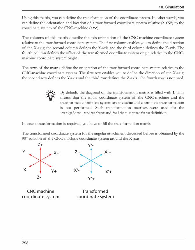
10. Simulation
793
Using this matrix, you can define the transformation of the coordinate system. In other words, you can define the orientation and location of a transformed coordinate system relative (X’Y’Z’) to the coordinate system of the CNC-machine (XYZ).
The columns of this matrix describe the axis orientation of the CNC-machine coordinate system relative to the transformed coordinate system. The first column enables you to define the direction of the X-axis; the second column defines the Y-axis and the third column defines the Z-axis. The fourth column defines the offset of the transformed coordinate system origin relative to the CNC-machine coordinate system origin.
The rows of the matrix define the orientation of the transformed coordinate system relative to the CNC-machine coordinate system. The first row enables you to define the direction of the X-axis; the second row defines the Y-axis and the third row defines the Z-axis. The fourth row is not used.
By default, the diagonal of the transformation matrix is filled with 1. This means that the initial coordinate system of the CNC-machine and the transformed coordinate system are the same and coordinate transformation is not performed. Such transformation matrixes were used for the workpiece_transform and holder_transform definition.
In case a transformation is required, you have to fill the transformation matrix.
The transformed coordinate system for the angular attachment discussed before is obtained by the 90° rotation of the CNC-machine coordinate system around the X-axis.
X+
X- Y+
Y-
Z+
Z-
X'+
X'- Z'+
Z'-
Y'-
Y'+
CNC machinecoordinate system
Transformedcoordinate system

794
The resulting transformation is the following:
Therefore the matrix has to be filled as shown below.
XML file structure
This topic describes the XML file structure using the Table-Table CNC-machine definition example.
The XML-based definition of a CNC-machine consists of several commands (tags), each of them describes the specific item of the CNC-machine definition tree.
Each tag is enclosed between the “<” and “>” signs.
Example:
<machine_definition>
Some XML constructions consist of opening and closing tags; the closing tag starts from the “/” symbol.
X(X'=+1)
Y(Z'=+1)
Z(Y'=-1)
X'(X=+1)
Y'(Z=-1)
Z'(Y=+1)
CNC-machinecoordinate system
Transformedcoordinate system

10. Simulation
795
Example:
<machine_definition>
CNC-machine definition tags
</machine_definition>
For some tags, opening and closing can be performed in the single tag.
Example:
<machine_data name=”Table_table” units=”metric” />
XML tags can contain a number of variables.
Example:
name=”Table_table”;
here name is the variable name and ”Table_table” is the value. The value must be enclosed in quotation marks.
The automatically generated XML file is the following:
The order of the commands (tags) of the XML file is the same as the order of the CNC-machine components in the CNC-machine definition tree.
<?xml version=”1.0” encoding=”iso-8859-1” ?>
This string is similar for each XML file; it describes the used version of XML format and encoding.
<machine_definition>
This tag starts the CNC-machine definition.
<machine_data name=”Table_table” units=”metric” />
This tag defines the name of the CNC-machine and the used units.
<axis id=”X” type=”translation” x=”1.00000000” y=”0.00000000” z=”0.00000000” minvalue=”-380.000000” maxvalue=”380.000000”>
This tag starts the X-axis definition. The <axis> tag enables you to define the type of the axis (translational/rotational), axis orientation and limits.
<geometry name=”Sliding carriage” geo=”table_table-x_axis-1.stl” clrr=”0.00000000” clrg=”0.00000000” clrb=”1.00000000” alpha=”0.0” reflectivity=”0.0” objtype=”geometry” />

796
This tag defines the geometry of the part performing X-axis movements. The name variable defines the geometry ID. The geo variable defines the STL file used for the geometry definition. The clrr, clrg and clrb variables define the RGB components of the geometry color. The values of these parameters have to be in the range from 0 to 1. The alpha variable defines the transparency of the geometry. The reflectivity variable defines the reflectivity of the geometry.
<axis id=”Z” type=”translation” x=”0.00000000” y=”0.00000000” z=”1.00000000” minvalue=”0.000000” maxvalue=”300.000000” >
<geometry name=”Spindle unit” geo=”table_table-z_axis-1.stl” clrr=”0.50196081” clrg=”1.00000000” clrb=”1.00000000” alpha=”0.0” reflectivity=”0.0” objtype=”geometry” />
The Z-axis definition.
<transform id=”holder_transform” initialvalue=”1.00000000, 0.00000000, 0.00000000, 0.00000000, 0.00000000, 1.00000000, 0.00000000, 0.00000000, 0.00000000, 0.00000000, 1.00000000, 0.00000000, 0.00000000, 0.00000000, 0.00000000, 1.00000000”>
This tag starts the tool transformation definition. The initialvalue variable defines the used transformation matrix.
<geometry name=”tool” geo=”tool.stl” clrr=”0.00000000” clrg=”1.00000000” clrb=”0.00000000” alpha=”0.0” reflectivity=”0.0” objtype=”tool” holderr=”0.00000000” holderg=”1.00000000” holderb=”1.00000000” />
This tag defines the geometry of the tool (with the tool holder). The clrr, clrg and clrb variables define the RGB components of the tool color. The holderr, holderg and holderb variables define the RGB components of the tool holder color.
</transform>
Closing tag for the tool transformation definition.
</axis>
Closing tag for the Z-axis definition.
</axis>
Closing tag for the X-axis definition.
<axis id=”Y” type=”translation” x=”0.00000000” y=”-1.00000000” z=”0.00000000” minvalue=”-350.000000” maxvalue=”350.000000”>
Start Y-axis definition.

10. Simulation
797
<geometry name=”saddle” geo=”table_table-y_axis-1.stl” clrr=”0.00000000” clrg=”0.50196081” clrb=”1.00000000” alpha=”0.0” reflectivity=”0.0” objtype=”geometry” />
Definition of the CNC-machine part performing Y-axis movements.
<axis id=”B” type=”rotation” x=”-1.00000000” y=”0.00000000” z=”0.00000000” minvalue=”-100.000000” maxvalue=”100.000000” rzx=”0.00000000” rzy=”0.00000000” rzz=”-30.00000000”>
Start B-axis definition. For rotational axes the rzx, rzy and rzz variables define the location of the rotation base point.
<geometry name=”tilting table” geo=”table_table-b_axis-1.stl” clrr=”1.00000000” clrg=”0.50196081” clrb=”0.00000000” alpha=”0.0” reflectivity=”0.0” objtype=”geometry” />
Definition of the CNC-machine part performing B-axis movements.
<axis id=”C” type=”rotation” x=”0.00000000” y=”0.00000000”
z=”-1.00000000” minvalue=”-1000.000000” maxvalue=”1000.000000” rzx=”0.00000000” rzy=”0.00000000” rzz=”0.00000000”>
Start C-axis definition.
<geometry name=”Rotary table” geo=”table_table - table-1.stl” clrr=”0.50196081” clrg=”0.50196081” clrb=”1.00000000” alpha=”0.0” reflectivity=”0.0” objtype=”geometry” />
Definition of the CNC-machine part performing C-axis movements.
<transform id=”workpiece_transform” initialvalue=”1.00000000, 0.00000000, 0.00000000, 0.00000000, 0.00000000, 1.00000000, 0.00000000, 0.00000000, 0.00000000, 0.00000000, 1.00000000, 0.00000000, 0.00000000, 0.00000000, 0.00000000, 1.00000000”>
This tag starts the workpiece transformation definition. The initialvalue variable defines the used transformation matrix.
<geometry name=”werkstueck” geo=”werkstueck.stl” clrr=”0.00000000” clrg=”1.00000000” clrb=”0.00000000” alpha=”0.0” reflectivity=”0.0” objtype=”workpiece” />
Workpiece geometry definition.
<geometry name=”stock” geo=”stock.stl” clrr=”0.00000000” clrg=”1.00000000” clrb=”0.00000000” alpha=”0.0” reflectivity=”0.0” objtype=”stock” />
Stock geometry definition.
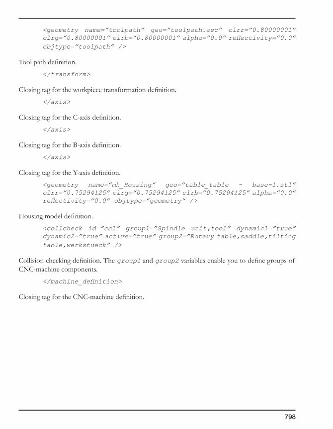
798
<geometry name=”toolpath” geo=”toolpath.asc” clrr=”0.80000001” clrg=”0.80000001” clrb=”0.80000001” alpha=”0.0” reflectivity=”0.0” objtype=”toolpath” />
Tool path definition.
</transform>
Closing tag for the workpiece transformation definition.
</axis>
Closing tag for the C-axis definition.
</axis>
Closing tag for the B-axis definition.
</axis>
Closing tag for the Y-axis definition.
<geometry name=”mh_Housing” geo=”table_table - base-1.stl” clrr=”0.75294125” clrg=”0.75294125” clrb=”0.75294125” alpha=”0.0” reflectivity=”0.0” objtype=”geometry” />
Housing model definition.
<collcheck id=”cc1” group1=”Spindle unit,tool” dynamic1=”true” dynamic2=”true” active=”true” group2=”Rotary table,saddle,tilting table,werkstueck” />
Collision checking definition. The group1 and group2 variables enable you to define groups of CNC-machine components.
</machine_definition>
Closing tag for the CNC-machine definition.

SolidCAMSettings 12
The SolidCAM Settings feature enables you to define a set of SolidCAM defaults such as folders, units, tolerances, CNC-controllers, etc.
In the settings dialog box, you can change the path to related applications, units, tolerances, default machines, editors, and color settings for SolidCAM. The Settings register enables you to easily view and edit the current program preferences and options.
User Directories settings
Units settings
Simulation settings
Synchronization settings
Rest Material & SolidVerify settings
Tool settings

800
12.1 Introduction
The SolidCAM Settings dialog box enables you to change the path to related applications, units, tolerances, default machines, editors, and color settings for SolidCAM. This dialog box enables you to easily view and edit the current program preferences and options.
The following pages are available in the SolidCAM Settings dialog box:
• Userdirectories
• DefaultCNC-Controller
• Units
• Synchronization
• CompressedCAM-Part
• UpdatedStock&SolidVerify
• Toolsettings
• Colorsettings
• DefaultGeometryNames
• Interoperationaltoolmovements
• Auto-save
• AutomaticCAM-Partdefinition
• Toolpathsimulation
• Machinesimulation
• DNCsettings
• Editors
• ExternalProgram
• MachiningProcess
• Userinterface
• CoordSysdefinition
• GCodegeneration
• Toolsearchsettings
• Internalpost-processor
• SolidCAMManager
• Templatedefaults
• Miscellaneoussettings
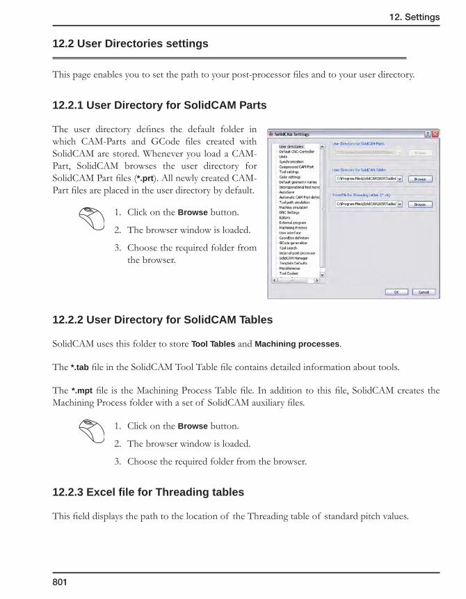
12. Settings
801
12.2 User Directories settings
This page enables you to set the path to your post-processor files and to your user directory.
12.2.1 User Directory for SolidCAM Parts
The user directory defines the default folder in which CAM-Parts and GCode files created with SolidCAM are stored. Whenever you load a CAM-Part, SolidCAM browses the user directory for SolidCAM Part files (*.prt). All newly created CAM-Part files are placed in the user directory by default.
1. Click on the Browse button.
2. The browser window is loaded.
3. Choose the required folder from the browser.
12.2.2 User Directory for SolidCAM Tables
SolidCAM uses this folder to store Tool Tables and Machining processes.
The *.tab file in the SolidCAM Tool Table file contains detailed information about tools.
The *.mpt file is the Machining Process Table file. In addition to this file, SolidCAM creates the Machining Process folder with a set of SolidCAM auxiliary files.
1. Click on the Browse button.
2. The browser window is loaded.
3. Choose the required folder from the browser.
12.2.3 Excel file for Threading tables
This field displays the path to the location of the Threading table of standard pitch values.

802
12.3 Default CNC-controller settings
12.3.1 Post-processor files directory
GPP files with the extensions *.mac and *.gpp are post-processor files used by SolidCAM.
The *.mac file contains information about the CNC-machine, e.g. number of simultaneous axes, available cycles, default tool positioning, etc.
The *.gpp file translates the calculated tool path into GCode. The GCode format, cycle definitions, etc. of your GCode file is controlled in this file.
You have to specify the path to the folder where you keep the *.mac and *.gpp files you have received from SolidCAM. The post-processors that come with the evaluation or demo version are installed in the SolidCAM program directory.
1. Click on the Browse button.
2. The browser window will be loaded.
3. Choose the folder you want from the browser.
12.3.2 CNC-controllers
SolidCAM enables you to define the following default machine controllers:• MillingCNC-Controller
• TurningCNC-Controller
• Milling&TurningCNC-Controller
• WireCutCNC-Controller
• Mill-TurnCNC-Controller
The chosen post-processor will be used as a default machine, which means it will appear in the Milling Part Data dialog box as the controller for a new CAM-Part. Naturally, you can change the controller for the CAM-Part with the list field if you want to use another machine controller.
1. Click on the Browse button. A list of post-processors available in your Post-processor files directory will be displayed in the Machines list.
2. Double-click on the machine you want to use as default.
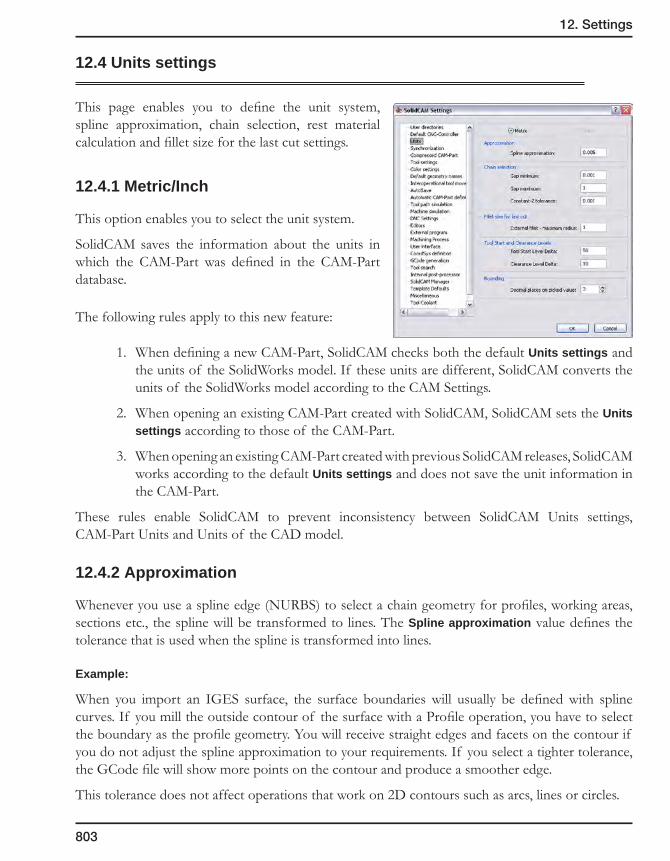
12. Settings
803
12.4 Units settings
This page enables you to define the unit system, spline approximation, chain selection, rest material calculation and fillet size for the last cut settings.
12.4.1 Metric/Inch
This option enables you to select the unit system.
SolidCAM saves the information about the units in which the CAM-Part was defined in the CAM-Part database.
The following rules apply to this new feature:
1. When defining a new CAM-Part, SolidCAM checks both the default Units settings and the units of the SolidWorks model. If these units are different, SolidCAM converts the units of the SolidWorks model according to the CAM Settings.
2. When opening an existing CAM-Part created with SolidCAM, SolidCAM sets the Units settings according to those of the CAM-Part.
3. When opening an existing CAM-Part created with previous SolidCAM releases, SolidCAM works according to the default Units settings and does not save the unit information in the CAM-Part.
These rules enable SolidCAM to prevent inconsistency between SolidCAM Units settings, CAM-Part Units and Units of the CAD model.
12.4.2 Approximation
Whenever you use a spline edge (NURBS) to select a chain geometry for profiles, working areas, sections etc., the spline will be transformed to lines. The Spline approximation value defines the tolerance that is used when the spline is transformed into lines.
Example:
When you import an IGES surface, the surface boundaries will usually be defined with spline curves. If you mill the outside contour of the surface with a Profile operation, you have to select the boundary as the profile geometry. You will receive straight edges and facets on the contour if you do not adjust the spline approximation to your requirements. If you select a tighter tolerance, the GCode file will show more points on the contour and produce a smoother edge.
This tolerance does not affect operations that work on 2D contours such as arcs, lines or circles.

804
12.4.3 Chain selection
The Automatic selection function for chain geometries uses certain tolerances to decide whether two consequent elements are connected or independent. The behavior of this function depends on the Gap between the entities.
Gap minimum and Gap maximum tolerance
The Auto select feature (see topic 4.5.7) can function in three different ways:
• If the gap between the edges is smaller than the minimum chain gap, the system automatically continues the chain and closes the gap.
• If the gap is between the minimum and maximum values, you are asked whether the gap should be closed. If you answer Yes, the gap is automatically closed.
• If the gap is larger than the maximum value for a chain gap, the following message is displayed:
These tolerances can be defined separately for each geometry in the Geometry Edit dialog box (see topic 4.5).
Constant-Z Tolerance
When you work in the Auto Constant Z mode, all connected entities on the same Z-level of the current coordinate system will be selected. This tolerance defines the maximum deviation from the Z plane where an element will still be recognized as being on the same Z-level.
The Gap and Constant Z tolerances you should use depend mainly on the size of your geometries and the accuracy of your models or imported 2D/3D files. The default setting can be used for most of the common models, but when you work with very intricate CAM-Parts, for example, a large max. gap tolerance can cause problems as you might close contours in places that should normally be not connected. To avoid this, answer No to the message “Do you want to close the gap?” and switch to single curve mode to make sure you selected the correct elements.
Gap
12. Settings
805
12.4.4 Fillet size for last cut
This parameter defines the maximum allowed value of the radius for the external fillet.
For more information on the Fillet size for last cut option, see topic 6.1.2.
12.4.5 Tool Start and Clearance Levels
During each Coordinate System definition, SolidCAM automatically sets the Tool Start Level and Clearance Level values.
The Tool start level defines the Z-level at which the tool will start.
The Clearance level is the Z-level to which the tool rapids when moving from one operation to another (in case the tool did not change).
These parameters are defined relative to the Part Upper Level parameter according to the following formulas:
Tool Start Level = Part Upper Level + Tool Start Level Delta;
Clearance Level = Part Upper Level + Clearance Level Delta;
where the Clearance Level Delta and Tool Start Level Delta are constant values defined in the SolidCAM Settings.
The defined values of the Clearance Level Delta and Tool Star Level Delta will be used for the each CoordSys defined by SolidCAM including CoordSys positions automatically defined by SolidCAM AFRM module.
Default values:
Metric:
Tool Start Level Delta = 50; Clearance Level Delta = 10
Inch:
Tool Start Level Delta = 2; Clearance Level Delta = 0.4
SolidCAM have to use round numbers for Tool Start Level and Clearance Level values.
SolidCAM enables you to define the number of decimal units for rounding via the Rounding box of the SolidCAM Settings dialog box.
• The default value of Decimal places for Metric is 0.
• The default value of Decimal places for Inch is 3.

806
12.5 Synchronization settings
12.5.1 Synchronization of CAM geometry with design model
Check synchronization always
The synchronization check is performed automatically each time you click on the SolidCAM Manager tree.
• Askbeforesynchronizationcheck
When this check box is selected, after every change in the part or in the assembly and rebuild, SolidCAM will prompt you before checking the synchronization of the geometries with the model or sketches.
When this check box is not selected, the synchronization checking will be performed without any message or question.
• Synchronizeautomatically
This option enables you to perform the synchronization of geometries automatically.
When this check box is selected, the synchronization check is performed and then all the unsynchronized operations and geometries are automatically synchronized. When the synchronization fails for certain operations or geometries, SolidCAM marks the operations/geometries with an exclamation mark and deletes the operation tool path; such operations are marked with asterisk.
This option is available only when the Check synchronization always check box is selected.
• Calculateoperationsafterthesynchronization
This option enables you to perform the calculation of the synchronized operations automatically. When this check box is selected, SolidCAM automatically calculates all the synchronized operations. The operations marked with the exclamation mark are not calculated.
This option is available only when the Automatically synchronize geometries check box is selected.

12. Settings
807
Check synchronization on user demand
In this case, SolidCAM will not check the synchronization automatically. The Check Synchronization item in the Operation and Geometry menus is enabled and you can choose it to start the synchronization.
12.5.2 Synchronization tolerance
These parameters define the value of the synchronization tolerance. During the synchronization check, SolidCAM compares the SolidCAM geometry and the SolidWorks model. If the difference between them is out of the specified tolerance (the SolidWorks model was updated); you have to synchronize the geometry with the updated model.
• WireframeGeometry
The value of the tolerance for the Wireframe geometry.
• 3DModelGeometry
The value of the tolerance for the 3D Model geometry.
12.5.3 Synchronization of design model with original model
Ask user to find original model if not located
Every time the CAM-Part is opened, SolidCAM automatically checks the correspondence of the dates of the CAM-Part and the original SolidWorks design model. When the date of the original SolidWorks model is later than the date of the CAM-Part creation, this means that the SolidWorks original model has been updated. You can then replace the SolidWorks design model on which the CAM-Part is based with the updated SolidWorks design model.
The Ask user to find original model if not located option defines the sequence of SolidCAM operations in the case of the absence the original model. This option enables you to display the browser window to find the original model if the model was not found in the location specified in the CAM-Part.
12.5.4 Synchronization when design model configuration changes
This section enables you to define the synchronization settings if the configuration is changed. In this case, the default Part Settings (see topic 2.10.4) of each newly defined CAM-Part are used for synchronization.

808
12.6 Compressed CAM-Part settings
This page contains a number of options related to working with the compressed CAM-Parts (see topic 2.11).
New CAM-Part
Create new CAM-Parts in compressed mode. When this option is active, SolidCAM creates new CAM-Parts in the compressed mode.
Open CAM-Part
Compressed is a default Filter Type. This option enables you to define the default file type for the filter in the Open and Delete browser dialog boxes.
Close CAM-Part
Convert non-compressed CAM-Parts to compressed mode. When this option is active, each non-compressed CAM-Part loaded into SolidCAM will be converted to compressed mode.
SolidCAM Temporary folder
This field displays the current path for the SolidCAM Temporary folder and enables the user to choose a new one. Enter a new path name or choose it with the Browse button. The SolidCAM Temporary folder location cannot be changed when a CAM-Part is opened.
Only an existing folder can be defined. Otherwise, the following message will be displayed.
You have to define a new location for the SolidCAM Temporary folder.
When opening, SolidCAM checks the existence of the temporary folder and possibility to save files in it (via attributes). If the folder does not exist SolidCAM displays the following message.
You have to define a new location for the SolidCAM Temporary folder.
If the SolidCAM Temporary folder has attributes that enable file saving (read-only flag), SolidCAM will remove these attributes.

12. Settings
809
If the default folder (C:\Documents and Settings\<user name>\Local Setting\SolidCAM Temporary files) does not exist, but is chosen in SolidCAM Settings, SolidCAM will create it automatically.
Compression factor
This option enables you to control the performance and ratio of the compression for compressed CAM-Parts. A higher setting results in slower compression but more compact compressed CAM-Parts.

810
12.7 Tool Settings
12.7.1 Update Part Tool Table according to Machine Tool Table
By setting this option the user instructs SolidCAM to automatically update the Part Tool Table with tools from the Machine tool table defined in the MAC-file, when the CNC-controller for the CAM-Part is changed.
Only used tools numbers
This option enables you to update only those tools that were used in operations. Tools that were not used will be removed from the Part Tool Table. Used tools that were not found in the Machine Tool Table will be numbered with the next sequential numbers.
Renumber tools from 1 when there is no machine tool table
The option removes all unused tools from the Part Tool Table. The used tools will be renumbered starting from number 1. If the Renumber tools from 1 when there is no Machine tool table option is not active, SolidCAM removes all unused tools from the Part Tool Table. The used tools will not be renumbered.
This option is available only if the Only used tools numbers option is activated and only if the Machine Tool Table is not defined for the MAC of the new CNC-controller.
12.7.2 Print in documentation – Only used tools
This option enables SolidCAM to include in the CAM-Part documentation only the tools from the Part Tool Table used in operations.
12.7.3 Show in SolidCAM Manager
This option enables you to display the tool headers in SolidCAM Manager, whenever a new tool is used. The Tool header is displayed before the operation where the new tool is used.
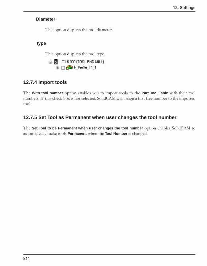
12. Settings
811
Diameter
This option displays the tool diameter.
Type
This option displays the tool type.
12.7.4 Import tools
The With tool number option enables you to import tools to the Part Tool Table with their tool numbers. If this check box is not selected, SolidCAM will assign a first free number to the imported tool.
12.7.5 Set Tool as Permanent when user changes the tool number
The Set Tool to be Permanent when user changes the tool number option enables SolidCAM to automatically make tools Permanent when the Tool Number is changed.

812
12.8 Color settings
This page enables you to customize the colors used in SolidCAM.
To change a color, click on the corresponding color button. The standard Windows Color selection dialog box will be displayed, enabling you to pick the color you want.
Customizable display elements:
• CoordSys: displays the color of the current Coordinate System.
• Direction arrow: displays the color of arrows that indicate the direction of a chain geometry.
• Point: displays the color of points during chain selection, e.g. the start point of an element.
• Numbers: displays the color of numbers used to identify chain geometries.
• Section: displays the color of the section geometries.
• Clamp: displays the color of the clamp in SolidCAM Turning.
• Show tool: displays the color of the tool shown from the operation dialog box.
• Open edges: displays the color of the open edge geometry.

12. Settings
813
• Pick highlight: highlights selected elements, e.g. surfaces, solids, lines, etc.
• Show chain/3D model/Drill: displays the color of geometries when you use the Show Geometry command.
• Chain Accept highlight: displays the color of chains that have been added to the currently active geometry.
• General chain selection: highlights entities suggested as consequent elements of the chain in auto select mode.
• Limit/Working area: displays the color of the Limit geometry and Working area geometry.
• Material boundaries: displays the color of the Material boundaries.
• Vertical Type Def. Depth: displays the color of numbers used to identify the depth of the vertical type variable profile depth.
• Sloped Type Def. Depth: displays the color of numbers used to identify the depth of the sloped type variable profile depth.
Load default color set
This option enables you to load the default colors of SolidCAM.
Host CAD background color
You can load a pre-defined set of colors for the customizable display elements. These colors have been selected by SolidCAM for the standard background colors of the Host CAD systems used by SolidCAM.
Choose the background color of the Host CAD from the list.
The Autoadjustoption enables you to load the optimal colors for the background of your Host CAD.
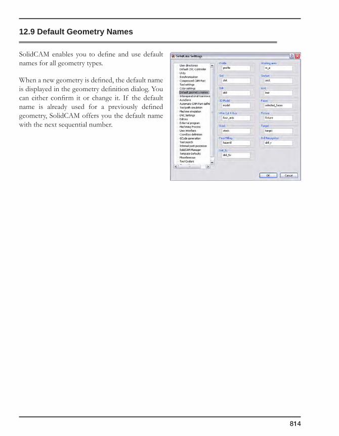
814
12.9 Default Geometry Names
SolidCAM enables you to define and use default names for all geometry types.
When a new geometry is defined, the default name is displayed in the geometry definition dialog. You can either confirm it or change it. If the default name is already used for a previously defined geometry, SolidCAM offers you the default name with the next sequential number.
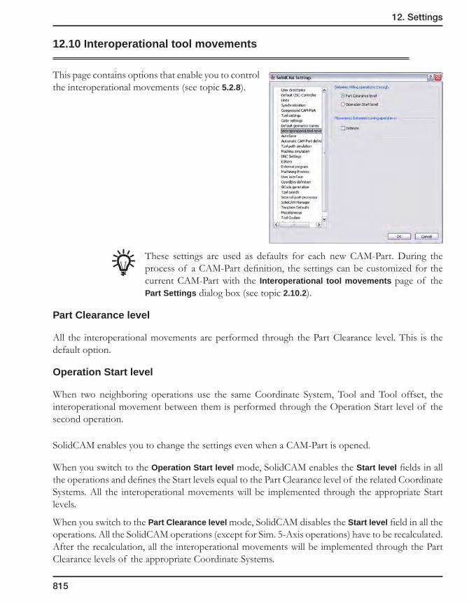
12. Settings
815
12.10 Interoperational tool movements
This page contains options that enable you to control the interoperational movements (see topic 5.2.8).
These settings are used as defaults for each new CAM-Part. During the process of a CAM-Part definition, the settings can be customized for the current CAM-Part with the Interoperational tool movements page of the Part Settings dialog box (see topic 2.10.2).
Part Clearance level
All the interoperational movements are performed through the Part Clearance level. This is the default option.
Operation Start level
When two neighboring operations use the same Coordinate System, Tool and Tool offset, the interoperational movement between them is performed through the Operation Start level of the second operation.
SolidCAM enables you to change the settings even when a CAM-Part is opened.
When you switch to the Operation Start level mode, SolidCAM enables the Start level fields in all the operations and defines the Start levels equal to the Part Clearance level of the related Coordinate Systems. All the interoperational movements will be implemented through the appropriate Start levels.
When you switch to the Part Clearance level mode, SolidCAM disables the Start level field in all the operations. All the SolidCAM operations (except for Sim. 5-Axis operations) have to be recalculated. After the recalculation, all the interoperational movements will be implemented through the Part Clearance levels of the appropriate Coordinate Systems.
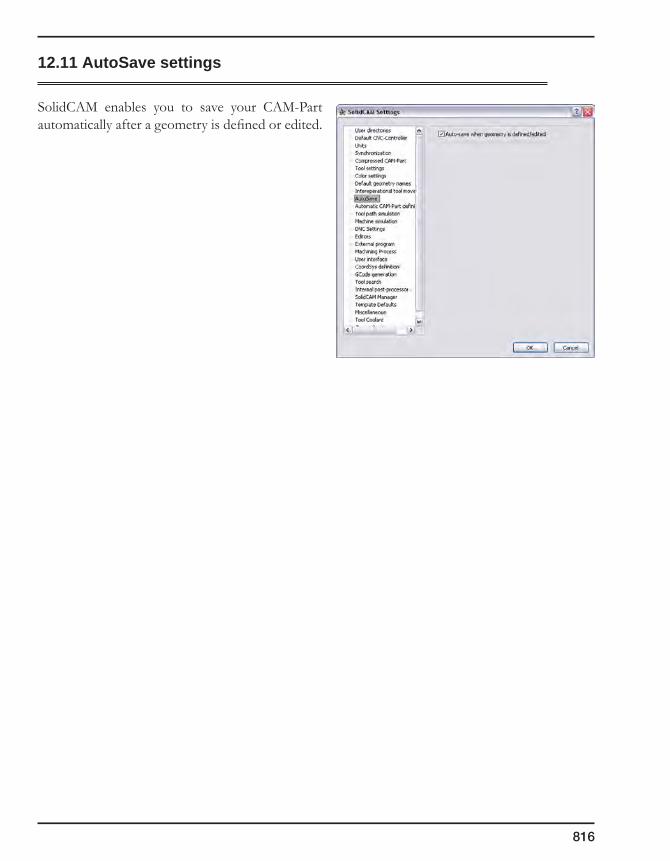
816
12.11 AutoSave settings
SolidCAM enables you to save your CAM-Part automatically after a geometry is defined or edited.
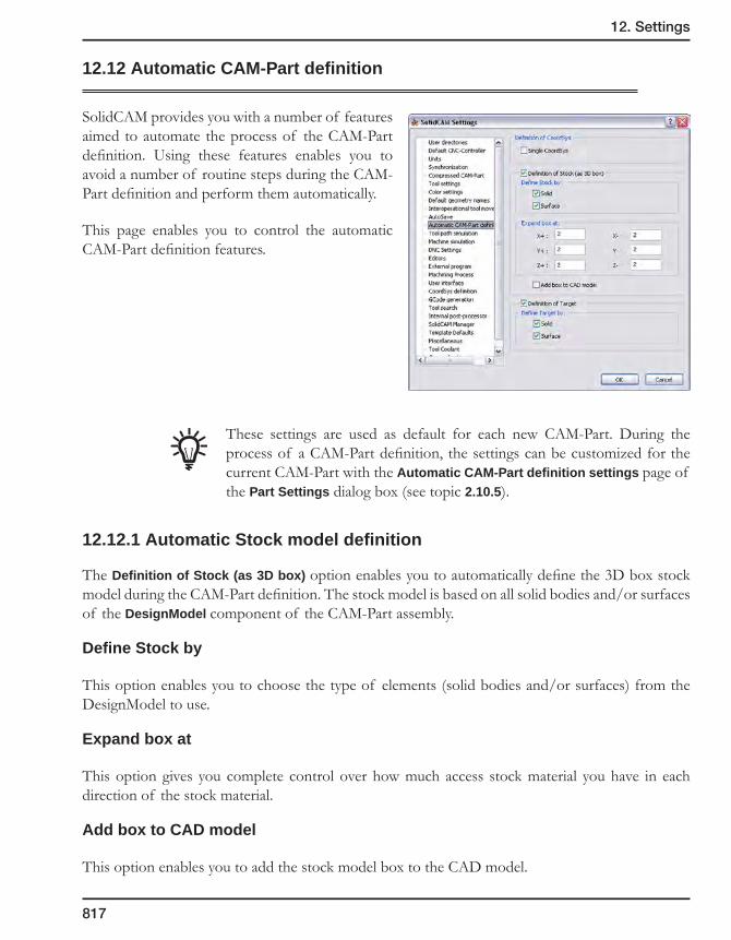
12. Settings
817
12.12 Automatic CAM-Part definition
SolidCAM provides you with a number of features aimed to automate the process of the CAM-Part definition. Using these features enables you to avoid a number of routine steps during the CAM-Part definition and perform them automatically.
This page enables you to control the automatic CAM-Part definition features.
These settings are used as default for each new CAM-Part. During the process of a CAM-Part definition, the settings can be customized for the current CAM-Part with the Automatic CAM-Part definition settings page of the Part Settings dialog box (see topic 2.10.5).
12.12.1 Automatic Stock model definition
The Definition of Stock (as 3D box) option enables you to automatically define the 3D box stock model during the CAM-Part definition. The stock model is based on all solid bodies and/or surfaces of the DesignModel component of the CAM-Part assembly.
Define Stock by
This option enables you to choose the type of elements (solid bodies and/or surfaces) from the DesignModel to use.
Expand box at
This option gives you complete control over how much access stock material you have in each direction of the stock material.
Add box to CAD model
This option enables you to add the stock model box to the CAD model.
818
12.12.2 Automatic Target model definition
The Definition of Target option enables you to automatically define the target model during the CAM-Part definition. The target model is based on all the solid bodies and/or surfaces of the DesignModel component of the CAM-Part assembly.
Define Target by
This option enables you to choose the type of elements (solid bodies and/or surfaces) from the DesignModel.
12.12.3 Definition of Coordinate System
Single CoordSys
When this check box is selected, SolidCAM enables you to shorten the CoordSys definition by avoiding the CoordSys Manager dialog box after the first CoordSys definition. This option is useful when defining CAM-Parts that use only one Coordinate System.
When this check box is not selected, SolidCAM displays the CoordSys Manager dialog box after the first CoordSys definition. The CoordSys Manager enables you to define an additional Coordinate System. This option is useful when defining CAM-Parts that use several Coordinate Systems.

12. Settings
819
12.13 Tool path simulation settings
The Tool path simulation settings enable you to customize the color of the tools used during the Turning simulation mode.
For each tool number you can define a separate color. The colors selected in this dialog box will be used for tools of current and future parts.
To change a color, click on the color symbol next to the tool number in the list. The standard Windows Color selection dialog box will be displayed, enabling you to pick the required color.
Load Default colors
Click on this button to load the default SolidCAM color settings for simulation.
Default simulation option
SolidCAM enables you to define the default simulation mode.
• UseHostCADSimulationasdefault
When this option is chosen, the Host CAD simulation mode is used as default for each new simulation session.
• Remember last simulation option
When this option is chosen, the simulation starts in the last used mode.
Gouge check
The Turn on Gouge check by default check box enables you to perform automatic gouge checking during the tool path simulation.

820
12.14 Machine simulation settings
This page enables you to define the settings of the Machine simulation mode (see topic 10.10).
12.14.1 Directory for Machine simulation definition
This parameter defines the location of the CNC-machines definition files used for the Machine simulation. A number of CNC-machine subfolders are located under this folder. According to the settings of the MAC file, the appropriate machine is chosen for the Machine simulation.
12.14.2 Tool path coordinates
This section enables you to define the type of coordinates that will be displayed in the Move list tab (see topic 10.10.2). The Part based coordinates option enables you to display the coordinates related to the CAM-Part coordinate system (part coordinates). The Absolute machine axis values option enables you to display coordinates related to the CNC-Machine origin (machine coordinates).
12.14.3 Background
Background color
This option enables you to choose the color for the Machine simulation background. The Color dialog box enables you to choose the appropriate color.
Background gradient
This option enables you to choose the colors for the Machine simulation gradient background. The Color dialog box enables you to choose the appropriate colors.
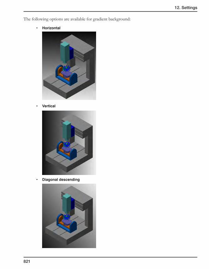
12. Settings
821
The following options are available for gradient background:
• Horizontal
• Vertical
• Diagonaldescending

822
• Diagonalascending
12.14.4 Enable collision control
This option enables you to detect and avoid possible collisions between all components of the CNC-machine in the process of machining. When the Enable collision control check box is selected, SolidCAM performs the collision checking according to the collision control parameters in the CNC-machine definition. When the Enable collision control check box is not selected, SolidCAM ignores the collision control parameters in the CNC-machine definition and does not perform the collision control.
Collision check tolerance
This parameter enables you to specify the tolerance of the collision check. SolidCAM ignores all the collisions with tolerance smaller than the specified value and alerts when the collision tolerance is greater than the tolerance specified value.
Collision control between moves
Generally, SolidCAM performs the collision control in the generated tool path positions listed in the GCode output. The Collision control between moves option enables you to perform the collision control also between these positions.
12.14.5 Solid verification
SolidCAM enables you to perform the solid verification of the material cutting process in the SolidVerify mode integrated into the Machine simulation. Using this functionality, you can display the stock model and perform the simulation by dynamic subtraction of the tool solid model (using solid Boolean operations) from the stock solid model.
When the Enable verification check box is selected, the solid verification is performed in the Machine simulation mode.

12. Settings
823
12.14.6 Environment
This check box enables you to edit the CNC-machine definition in the Machine simulation environment.
12.15 DNC settings
This option enables you to define the path for the data transmitting software – the DNC program.
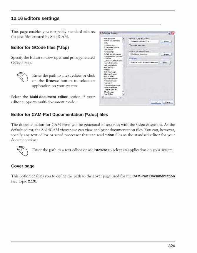
824
12.16 Editors settings
This page enables you to specify standard editors for text files created by SolidCAM.
Editor for GCode files (*.tap)
Specify the Editor to view, open and print generated GCode files.
Enter the path to a text editor or click on the Browse button to select an application on your system.
Select the Multi-document editor option if your editor supports multi-document mode.
Editor for CAM-Part Documentation (*.doc) files
The documentation for CAM Parts will be generated in text files with the *.doc extension. As the default editor, the SolidCAM viewer.exe can view and print documentation files. You can, however, specify any text editor or word processor that can read *.doc files as the standard editor for your documentation.
Enter the path to a text editor or use Browse to select an application on your system.
Cover page
This option enables you to define the path to the cover page used for the CAM-Part Documentation (see topic 2.13).
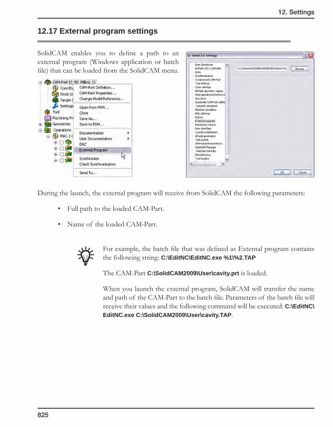
12. Settings
825
12.17 External program settings
SolidCAM enables you to define a path to an external program (Windows application or batch file) that can be loaded from the SolidCAM menu.
During the launch, the external program will receive from SolidCAM the following parameters:
• Full path to the loaded CAM-Part.
• Name of the loaded CAM-Part.
For example, the batch file that was defined as External program contains the following string: C:\EditNC\EditNC.exe %1\%2.TAP
The CAM-Part C:\SolidCAM2009\User\cavity.prt is loaded.
When you launch the external program, SolidCAM will transfer the name and path of the CAM-Part to the batch file. Parameters of the batch file will receive their values and the following command will be executed: C:\EditNC\EditNC.exe C:\SolidCAM2009\User\cavity.TAP.

826
12.18 Machining Process settings
12.18.1 On MP insertion (for milling only)
Perform auto calculation
Select this check box in case you want the operations to be calculated automatically after the Machining Process is inserted into the CAM-Part. If you select the Ask before calculation check box, the message is displayed which enables you to confirm the calculation; if this check box is cleared, the calculation starts without prior notice.
12.18.2 Operation name in SolidCAM Manager
The setting of this field defines how the operation names appear in SolidCAM Manager when a Machining Process Table is loaded and a Machining Process is added to the CAM-Part.
When the Show group name check box is selected, the operation names are preceded with the names of the operation groups and default sets defined in Machining Process Table Manager.
When this check box is not selected, only the operation names appear in the SolidCAM Manager tree.
12.18.3 Update extra parameters on CNC-controller change
This option enables you to update the extra parameters defined for the operation when the CNC-controller is changed. Select the Ask before update check box if you want the warning message to be displayed before the update is started.
Prismatic part_20-6_finish_wall
Operationgroup name
Default set name
Operationname

12. Settings
827
12.19 User interface settings
This page enables you to switch between two schemes of the SolidCAM operation interface.
While the first operation interface scheme is represented by a single-page dialog box, the other one is a dialog box divided into several pages, each of them handling a specific set of parameters (e.g. Geometry, Tool, Levels, Technology, and so forth). The list on the left enables you to switch between the parameters pages.
You may switch between the two interface schemes by using the corresponding options on this page. To choose the single-page interface, click Single-dialog. In this mode, you can also set a keyboard shortcut for switching between pages in the multi-page dialog box; click on the Switch Items Hotkey box and press a required key or a combination of keys you want to use as hotkeys for switching.
Single-page operation interface Multi-page operation interface
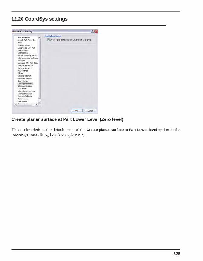
828
12.20 CoordSys settings
Create planar surface at Part Lower Level (Zero level)
This option defines the default state of the Create planar surface at Part Lower level option in the CoordSys Data dialog box (see topic 2.2.7).

12. Settings
829
12.21 GCode Generation
This page enables you to define the defaults of the GCode files location and other parameters. These defaults are applied to every newly created CAM-Part. If you want to modify these settings for each Part separately, SolidCAM offers you a similar page in the Part Settings dialog box (see topic 2.10.8).
The Save GCode files box offers three options to define the parameters related to saving of GCode files:
In the CAM-Part directory
SolidCAM saves the generated GCode files in the CAM-Part directory. This option is used by default.
According to the MAC file
SolidCAM saves the generated GCode files according to the parameters defined in the MAC file.
In the GCode directory
SolidCAM saves the generated GCode files in the specified GCode folder location. When the GCode generation is started, SolidCAM creates a new folder with the CAM-Part name in the specified GCode directory and saves the GCode files there. If this folder already exists, SolidCAM uses it for the GCode output.
This group box enables you to define the path for the GCode directory. You can enter the path or click on the Browse button and choose the destination folder using the Browse For Folder dialog box.
If you have entered the path to a non-existing folder, the following message is displayed after the confirmation of the SolidCAM Settings dialog box:

830
The Create button enables you to create the folder that will be used for GCode directory in the specified location. The Browse button displays the browser dialog box that enables you to choose another location that will be used for the GCode directory.
If the new folder cannot be created, the following message is displayed:
If the chosen folder has the read-only attribute, the following message is displayed after the confirmation of the Browse dialog box or the SolidCAM Settings dialog box:
By default, the GCode directory location is not defined. You have to specify it when you choose the In the GCode directory option for the first time.
Create subfolders for split GCode files
When split marks are detected in SolidCAM Manager during the GCode generation for the entire CAM-Part, SolidCAM creates a number of GCode segment files. Each such GCode segment file is created for one or several operations enclosed by split marks. These files are named with the CAM-Part name followed by the “-” sign and the order number of split segment.
Split marks are ignored in case of GCode generation for several operations.
With the In the GCode directory option, SolidCAM creates separate CAM-Part GCode folders in the specified folder location.
When the Create subfolders for split GCode files check box is selected, SolidCAM creates a separate folder for each GCode segment file and saves the GCode segments files there. The folder is created in the GCode folder of the CAM-Part in the specified GCode folder location. The name of the folder is the same as the GCode segment file name.

12. Settings
831
When the Create subfolders for split GCode files check box is not selected, SolidCAM generates all the GCode segment files directly into the GCode folder of the CAM-Part in the specified GCode folder location.
By default, the Create subfolders for split GCode files option is not selected.
Create separate folders for each CAM-Part
When this check box is selected, SolidCAM creates a folder for each CAM-Part and saves the GCode file there. Otherwise, the GCode files for all CAM-Parts are generated into the GCode directory.
Additional control of GCode
When this check box is selected, you can alter the GCode file name and location. When you click one of the GCode generation commands, the Windows-style Save GCode browser is displayed with the default CAM-Part name and location that might be edited.
All the GCode files previously generated for the current CAM-Part remain in the specified folder.
When this check box is not selected, the GCode is generated and automatically saved in the defined location.
832
GCode generation for the entire CAM-Part
The Erase all previous GCode files check box enables you to choose whether the old GCode files generated for this CAM-Part remain or are removed when a new one is generated.
This check box is not available if the Create a separate folder for Each CAM-Part check box is not selected and when the Customize GCode file name check box is selected.
GCode generation for the entire for separate operations
The Erase all previous GCode files check box enables you to choose whether the old GCode files generated for separate operations remain or are removed when a new one is generated.
This check box is not available if the Create a separate folder for Each CAM-Part check box is not selected and when the Customize GCode file name check box is selected.

12. Settings
833
12.22 Tool search
The Tool search page enables you to define the parameters that will be used as search criteria when the tool search is performed by tool parameters.
This page contains two sets of tool data for Milling and Turning tool search. To define the parameters you want to include in the search, select the relevant check boxes. The Select all and Clear all buttons enable you to select or clear all the check boxes in each section separately.
12.23 Internal Post-processor
This page enables you to define whether the GCode will contain the @tool_path_info output, which is a post-processor command that includes information about the tool path. You may choose for which types of machines this output will appear in the GCode by selecting the corresponding check boxes.
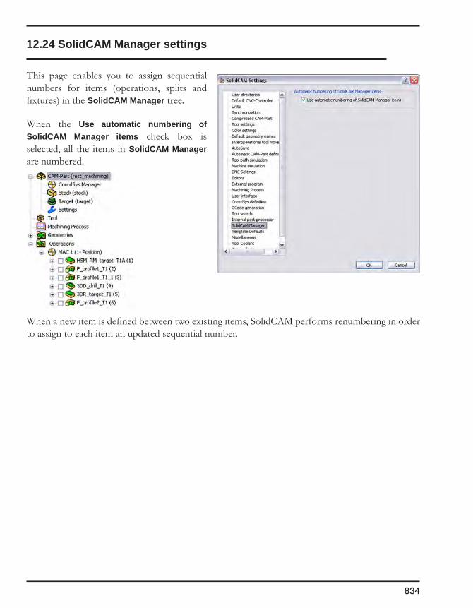
834
12.24 SolidCAM Manager settings
This page enables you to assign sequential numbers for items (operations, splits and fixtures) in the SolidCAM Manager tree.
When the Use automatic numbering of SolidCAM Manager items check box is selected, all the items in SolidCAM Manager are numbered.
When a new item is defined between two existing items, SolidCAM performs renumbering in order to assign to each item an updated sequential number.

12. Settings
835
12.25 Template defaults
This page enables you define the default location of the operation templates and to specify the default templates used for each new operation.
The content of this page is similar to that of the Template Defaults page of the Part Settings dialog box (see topic 2.10.9).
12.26 Miscellaneous settings
This page contains the Enable 3D mouse support check box that provides the possibility to use the SpaceNavigator 3D mouse by 3DConnexion (www.3dconnexion.com).
This device enables you to rotate, pan and zoom the CAD model at every stage of the CAM-Part definition. Working with the SpaceNavigator mouse, you can significantly speed up the geometry definition process and facilitate viewing the model and tool path when performing the simulation of machining in the HostCAD, Rest Material, SolidVerify, RapidVerify and Machine Simulation modes.
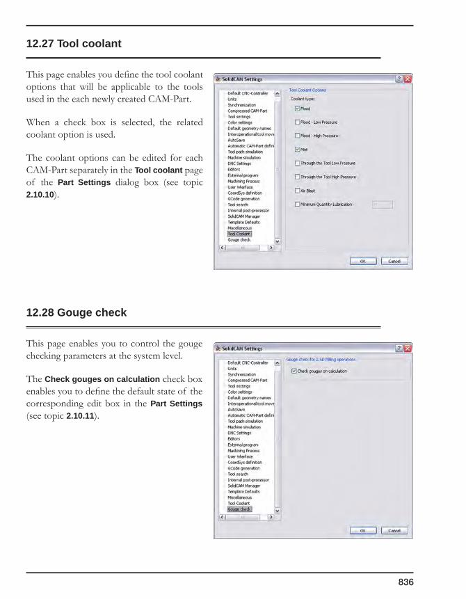
836
12.27 Tool coolant
This page enables you define the tool coolant options that will be applicable to the tools used in the each newly created CAM-Part.
When a check box is selected, the related coolant option is used.
The coolant options can be edited for each CAM-Part separately in the Tool coolant page of the Part Settings dialog box (see topic 2.10.10).
12.28 Gouge check
This page enables you to control the gouge checking parameters at the system level.
The Check gouges on calculation check box enables you to define the default state of the corresponding edit box in the Part Settings (see topic 2.10.11).

GCode 11This command enables you to generate and display the GCode file for the CAM-Part or for machining operations. The GCode file can then be transferred to your CNC-machine using a floppy disk, via the DNC (RS 232) or Ethernet connection.
The format of the NC-program depends on the Controller you selected in the Milling Part Data dialog box. The GCode output format can be customized using the GPP interface or by changing the controller’s *.mac and *.gpp files.
Generating the GCode
838
This command enables you to generate and display the GCode file for the CAM-Part or for machining operations. The GCode file can then be transferred to your CNC-machine using a floppy disk, via the DNC (RS 232) or Ethernet connection.
The format of the GCode depends on the Controller you selected in the Milling Part Data dialog box. The GCode output format can be customized either by using the GPP interface or by changing the controller’s *.mac and *.gpp files. Contact technical support for more information on post-processor customization.
The GCode files location is determined on the GCode Generation page of the Part Settings dialog box (see topic 2.10.8).
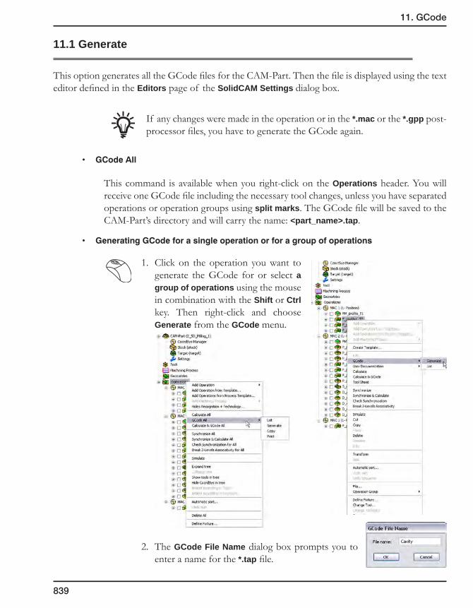
11. GCode
839
11.1 Generate
This option generates all the GCode files for the CAM-Part. Then the file is displayed using the text editor defined in the Editors page of the SolidCAM Settings dialog box.
If any changes were made in the operation or in the *.mac or the *.gpp post-processor files, you have to generate the GCode again.
• GCodeAll
This command is available when you right-click on the Operations header. You will receive one GCode file including the necessary tool changes, unless you have separated operations or operation groups using split marks. The GCode file will be saved to the CAM-Part’s directory and will carry the name: <part_name>.tap.
• GeneratingGCodeforasingleoperationorforagroupofoperations
1. Click on the operation you want to generate the GCode for or select a group of operations using the mouse in combination with the Shift or Ctrl key. Then right-click and choose Generate from the GCode menu.
2. The GCode File Name dialog box prompts you to enter a name for the *.tap file.

840
11.2 List
This option enables you to display a list of the already generated GCode files for the current CAM-Part or operation. The GCode (*.tap) file will be opened with the text editor defined in Editors Settings. Use the editor to change, save or print the GCode file.
11.3 Copy
This option enables you to copy GCode files. When you choose this option, the list of the generated GCode files for the current CAM-Part is displayed in the Copy GCode dialog box.
1. Choose the *.tap file you want to copy to another directory (for multiple selections, use the Ctrl or the Shift key).
2. Transfer the list of files you want to copy to the middle field by clicking the arrow.
3. Choose the drive and the directory you want to copy to.
4. Click on the Copy button in order to execute the command.
11.4 Print
This option enables you to print the GCode file.

Appendix
841
Appendix
SolidCAM Security Hardware Key
To prevent the unauthorized access to the software, SolidCAM is using the hardware protection key, the plug-in device that enables the software authentication. SolidCAM hardware keys are available both for USB and LPT ports to support both standalone and network usage.
To view the information about the hardware key you are using, click SolidCAM and choose Hardware Key Info from the menu.
The Hardware Key Info dialog box is displayed.
Key type
This section displays the type of the key you are using: either standalone or network.
• Standalone hardware key enables you to run SolidCAM only on one computer where the key is installed.
• Network hardware key enables you to run SolidCAM simultaneously on several computers connected to a local area network. There are two types of network hardware keys: non-configurable and configurable. A Non-configurable hardware key enables you to use the same set of available SolidCAM modules for all SolidCAM network users. A Configurable hardware key enables you to choose a specific set of modules for each SolidCAM network user.
Expiration date
This section displays the expiration date of the key.
Additional features
This section lists the additional modules, with which the current key enables you to work, such as the DNC software.
Modules
The list of CAM modules you can work with using this key.
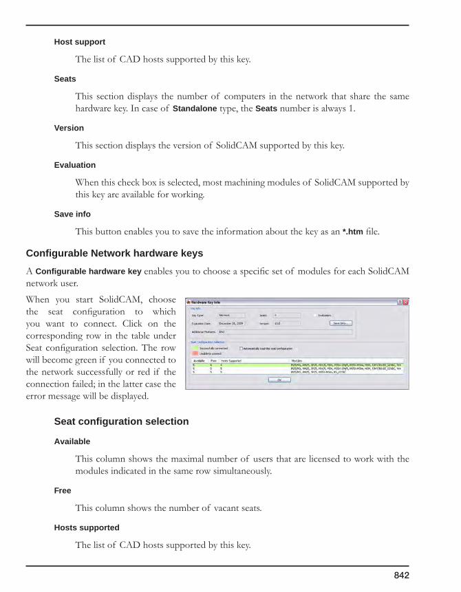
842
Host support
The list of CAD hosts supported by this key.
Seats
This section displays the number of computers in the network that share the same hardware key. In case of Standalone type, the Seats number is always 1.
Version
This section displays the version of SolidCAM supported by this key.
Evaluation
When this check box is selected, most machining modules of SolidCAM supported by this key are available for working.
Save info
This button enables you to save the information about the key as an *.htm file.
Configurable Network hardware keys
A Configurable hardware key enables you to choose a specific set of modules for each SolidCAM network user.
When you start SolidCAM, choose the seat configuration to which you want to connect. Click on the corresponding row in the table under Seat configuration selection. The row will become green if you connected to the network successfully or red if the connection failed; in the latter case the error message will be displayed.
Seat configuration selection
Available
This column shows the maximal number of users that are licensed to work with the modules indicated in the same row simultaneously.
Free
This column shows the number of vacant seats.
Hosts supported
The list of CAD hosts supported by this key.

Appendix
843
Modules
The list of CAM modules you can work with using this key.
Configuration # (optional)
In case you want to know which seat configuration is used on which host, this number enables you to identify the users that are currently using SolidCAM in the network with the help of the Aladdin Monitor utility. You can turn on this option in SolidCAM Settings if needed.
Automatically load this seat configuration
Select this check box if you wish to start SolidCAM always with the chosen configuration without displaying the Hardware Key Info dialog box. In case of connection failure the error message will be displayed.
CAM Modules list
M25 2.5D MillingRM25 Profile/Pocket 2.5D Rest Material and chamferingSP25 Special Additional 2.5D Mill OptionsAFRM Automatic Feature Recognition and Machining moduleDrillPocketRecog Pocket and Drill RecognitionM3 3D MillingHSM High Speed MachiningMI4 4-Axis Indexial MillingMI5 5-Axis Indexial MillingMS4 Simultaneous 4-Axis Milling (C-axis)MS5X-3 HSSMS5X-4 Sim. 5-Axis module - 4-AxisMS5X-5 Sim. 5-Axis module - 5-AxisMSim Machine SimulationT TurningT/MT-YC Turn-Mill - XYZC-axesT/MT-YBC Turn-Mill - XYZCB-axesBS Back SpindleW2 WireEDM 2-axesW4 WireEDM 2/4 axesDNC WinDNC application for NC data transfer

844
SolidCAM Security Hardware Key Update
In some cases SolidCAM requires the update of security hardware keys. To update the security hardware key, do the following:
1. Make sure that the SolidCAM security hardware key is connected to the computer.
2. Extract the ZIP-archive <security hardware key number>.zip supplied by SolidCAM into the ..\SolidCAMXXXX\Util folder
3. Extract the ZIP-archive customer.zip to the same folder.
4. Run the Mak_plag.bat file located in the ..\SolidCAMXXXX\Util folder. It is recommended to run it with the Command Prompt (Start > Programs > Accessories) window. When the Command prompt dialog box is displayed enter the following commands:
Cd <full path for SolidCAM folder>\Util
Mak_plag
By default, the full path for SolidCAM folder is the following: C:\Program Files\SolidCAMXXXX
5. The message: Hasp Memory updated OK will be displayed.

Index
845
Index
Symbols
2.5D Milling 3012D Boundary 582D simulation 6853D Box dialog box 593D Drilling Operation 5553D Engraving Operation 5513D Milling 4833D Milling Operation 4843D Model 583D Model Geometry 1973D simulation 6924th Axis 2965 Axis 73, 74@tool_path_info command 833
A
Add Center Drill 678Adding a new Parameter 579Adding an Operation 230Add Multi-Chain 213Adjacent passes connection 329, 367Adjacent tool paths connection 345Advanced sort 265Advanced sorting 414Advanced Technology 264AFRM 596Algorithm 650Angle 159, 530Angle along path 516Angle between paths 516Angle ramping parameters 384Angular dimensions 151Approach from outside 370, 405Approach open pocket from outside 507Approximation 803Approximation of arcs 274Arbor diameter 159Arc approximation 345, 366, 523, 535Arc by points 208Around 4th Axis Drill Geometry 194Around Profile 377, 508

846
Ask user to find original model if not located 807Assigning Hole Features to Feature Sets 642Associativity of Stock and Target models 61Automatically remove noise from input data 73Automatic CAM-Part definition 76, 817Automatic CoordSys Positions definition 643Automatic optional angle 362Automatic Sort 288Automatic Stock model definition 76, 817Automatic Target model definition 77, 818Auto next 308Auto-Save settings 816Auto Select 209Auto-to 209Axis Tolerance 677Axis type 66, 643
B
Background color 820Background gradient 820Ball nose mill 118Base Geometry 336Base points of rotation axes 751, 760Bitangential angle 546Blind 438Blind Simple Hol Feature 597Boolean Operations 226Bore 137Boring 435Box (Auto) 58Bull nose mill 119
C
CAD selection 193Calculate operations inside Holes Recognition 678Calculator 247CAM-Part Definition 94CAM-Part Documentation 97CAM-Part Lower level 52CAM-Part name 39CAM-Part Properties 94CAM-Part structure 40CAM-Part Upper level 52Capture Image 99Ceiling offset 466
Index
847
Center drill 132, 410Center of circle 331Chain Geometries 203Chains direction 205Chains direction dialog box 217Chains selection 215Chains sorting 218Chamfer 312, 314, 355, 376, 379, 406Chamfer drill 135Chamfer Hole Feature segment 605Chamfer Length 160Chamfer Machinable Hole Feature segment 619Change tool 280, 287Change tool data 280, 287Changing Angle 636, 638, 639Changing Diameter 636, 637, 638, 639Changing Height 636, 637, 638, 639Changing Upper Plane 636, 637, 638, 639Check faces 490Check gouges during calculation 273Check synchronization always 806Check synchronization on user demand 807Choose STL dialog box 59Choosing a Technological Solution 649Choosing the tool 589, 650Choosing the tool for the Center - Chamfer Drill Operation 654Choosing the tool for the Center Drill Operation 652Choosing the tool for the Chamfer Drill Operation 653Choosing the tool for the Drill Operation 651Choosing the tool for the Mill Operation 651Choosing the tool for the Reaming Operation 656Choosing the tool for the Thread Operation 655Circular Pocket 531Circular sorting methods 425Clean condition 368Clean contours of flat areas 536Clean flat 500Clearance level 52, 258Clear offset 317, 468Climb milling 537Closed chains direction 217CNC-controller 66, 802CNC-machine kinematic type 743Collapse tree 286Color settings 812Compare target and machined stock 699, 718Compatible Hole Features 646

848
Compatible/Incompatible Hole features 645Compensation 309, 375, 407, 450, 466, 511, 536Complete Z-level 372, 406, 457, 511Compound Hole Features 597Compound Holes processing 606Compressed CAM-Part 87Compressed CAM-Part file format 87Compressed CAM-Part settings 808Compression factor 809Condition 650, 667Cone Hole Feature segment 604Configurations page 664Conical fillet 268Connection type 527, 531, 532, 536Connect islands 364Constant depth type 310, 454Constant step down 534Constant Step over strategy 540Constant Z Finish Strategy 533Constant-Z flat floor machining 538Constant-Z Tolerance 804Constant-Z wall machining 534Constraint 481Contour 3D Operation 351Contour style 539Contour technology 343Contour type 364Conventional 537Conversion to Chamfer Machinable Hole Feature segment 630Conversion to Drill Machinable Hole Feature segment 628Conversion to Flat Chamfer Machinable Hole Feature segment 630Conversion to Flat Cylinder Machinable Hole Feature segment 629Conversion to Thread Machinable Hole Feature segment 631Converting CAM-Parts 88Coordinate System 41CoordSys data 52CoordSys dialog box 42CoordSys Manager 55CoordSys settings 828Copy 279Copy as Working area 221Corner 342, 363, 365Corner Radius 158Create planar surface at Part Lower level 54, 828Create separate folders for each CAM-Part 831Create subfolders for split GCode files 830Creating Feature Sets 642

Index
849
Current Configuration 665Current Stock model method 74Current Tool Library 142Curve 205Curve + Close corners 206Cut 279Cut from 470Cutter tip 445Cutting angle 679Cutting area 525Cutting depth overlap 469Cutting direction 342, 363, 460, 526, 530, 532, 537Cutting length 160Cylindrical/Conical face 43Cylindrical fillet 269Cylindrical Hole Feature segment 604
D
Default CNC-controller settings 802Default GCode numbers 68Default Geometry Names 814Default sets 562Default Sets page 576, 591Default Tool Data page 161Define Direction 522Define Operation Template 572Define start by angle 535Defining a new Technological Solution 673Defining Process Templates 240Definition of Coordinate Systems 77, 598, 818Delta 47Delta depth 258, 444, 456Depth 375Depth associativity 259Depth cutting type 321, 346, 455, 467Depth Edit dialog box 442Depth type 310, 445Descend to cutting level with Rapid 371, 406Descent Angle 458, 475Description 578Diameter 158, 443Diameter Offset Number 163, 256Diameter value 445Direction mode 546Direction type 530, 531Directory 39

850
Directory for Machine simulation definition 820Disconnected Holes processing 607Distance 594DNC settings 823Documentation Editor 97Dove tail mill 120Drill 131Drill cycle type 368, 434, 446, 558Drill depth 411, 444Drill Geometry 189Drill Geometry Selection dialog box 190Drilling 434Drilling Operation 409Drill Machinable Hole Feature segment 619Drill points 505Drill Recognition Operation 437Drive faces 490
E
Each step down 375Editors Settings 824Edit page 149Enable collision control 822End mill 117Engagement angle 270Engraving data for Translated Surface operation 474Engraving Limit for Translated Surface Operation 479Engraving technology 552Engraving tool 125Environment 823Equal step down 320, 359Equal step over 339, 372, 499Exit material 363, 364Expand tree 286Export all tools 155Export selected tools 155Expression 577, 578, 581, 668, 669Extend to edge 545Extension 306, 342, 345, 369, 405Extension/Overlap 319, 469External corner type 268External program settings 825External wall angle 267
F

Index
851
Face 399Face mill 121Face Milling Operation 335Facet rendering 711Facet tolerance 57F_Boring 436F_Drill 434Feature Sets 596, 642Feature Sets page 601, 645Feed 162, 255Feed and Speed defaults 184Fillet 365Fillet corner 344, 363Fillet size for last cut 315, 373, 406, 407, 456, 467, 501Final cuts 265, 406Find Holes 439Finish 319, 374, 407, 469, 514Finish strategies 520Fixture 298Flat approach/Flat retreat 452Flat Chamfer Machinable Hole Feature segment 619Flat Cylinder Machinable Hole Feature segment 619Flip 47Floor offset 317, 373, 407, 467Force open pockets as closed 506Found holes Undo/Redo 439Full diameter 445Functions 576
G
Gap control 212Gap maximum tolerance 804Gap minimum tolerance 804GCode 277, 837GCode button 247GCode generation 80, 829GCode output in machine/part coordinates 750Generating Operations 661Geometry 187Geometry Modify dialog box 401Geometry page 250, 358, 397Getting Help 36G (Global) 578Global TDB 663Gouge check 273Gouge check settings 86

852
Group Types 569
H
Hatch 339Hatch angle 340, 362Hatch+Finish type 367Hatch Roughing 513Hatch style 539Hatch type 361Head-Head machine type 743Head-Table machine type 745H Length 161Holder page 165Hole diameter 438Hole Feature Groups 607Hole Feature Model 603Hole Feature Parameters dialog box 608Hole Features 596Hole Feature segments 603Hole Feature shapes 607Hole Features page 601, 608Hole height 439Holes Recognition Functions 669, 674Holes Recognition Manager 599, 600Holes Recognition parameters 668, 671Holes Recognition Settings 676Holes Recognition Toolbar 601Holes Tree 439, 440, 442Holes type 438Hole Upper level 439Host CAD simulation 691HR Drill Geometry Selection dialog box 438HR Manager Toolbar 600
I
ID Number 158Import Tool 154Include tool data 235, 240Incompatible Hole Features 646Indent according to Tools/CoordSys 288Info 245, 281Init 293Inserting The Machining Process 587Installing SolidCAM 24Internal Post-processor 833
Index
853
Interoperational tool movements 71Interoperational Tool movements 261Invert Check Status 337Island offset 373, 407Island wall angle 267Item search in SolidCAM Manager 33
K
Keep cutting direction 341, 362Keep tool down 333, 349, 395
L
Lead in 330, 391, 408, 482Lead in/out arc 452Lead out 330, 393, 408, 482Length 160Length Offset number 163, 256Levels page 257, 303, 359, 403, 411License Manager 29Light control 690Limit data for translated surface 476Limit Geometry 202Limits 475Linear finish strategy 520Linear pattern 414Linear sorting methods 415Link page 381, 408, 482Loading Templates 237Local TDB 663Lollipop mill 127Lollipop mill with conical shoulder 128Lollipop mill without conical shoulder 127Loop 344, 365Loops filter 216Lower level (Depth) 258LPT port 29
M
Mac CoordSys number 42Machinable Hole Feature conversion 625Machinable Hole Features 596, 619Machinable Hole Features page 601, 633Machine CoordSys number 52Machine simulation 759

854
Machine simulation settings 820Machining Process 650Machining Process Define Manager 572Machining Process Group Types 569Machining Process Insert Manager 590Machining Process List 566Machining Process settings 826Machining Process Table 562Machining Process Table Manager 566Mac Options 65Major thread diameter 450Managing CAM-Parts 90Managing Geometries 220Managing Hole Features 609Managing Machinable Hole Feature Segments 633Managing Machining Processes 571Managing Machining Process Tables 567Managing Operation Templates 573Managing Technology 658Managing Technology Solutions 659Managing tools 152Mark open edges 204Mark Open Edges dialog box 213Max Distance between Holes 677Maximum angle 489Maximum step down 534Maximum step over 523, 538Measurement 701Milling CAM-Part 38Milling Part Data dialog box 40Milling STL CAM-Part 108Milling type 537Min. corner radius 365Minimal clean condition 368Minimum angle 489Minimum cut area 539Minimum step down 534Minimum step over 524Min. Overlap 339Mirror 296Miscellaneous parameters 272Model name 39Model Reference 93Modify 466Modify Geometry 305Modifying Chamfer Machinable Hole Feature segment 638Modifying Drill Machinable Hole Feature segment 635
Index
855
Modifying Flat Chamfer Machinable Hole Feature segment 639Modifying Flat Cylinder Machinable Hole Feature segment 637Modifying Machinable Hole Feature segments 634Modify offset 306MP Picture 566Multi-Passes 451
N
Nethasp.ini 30NethaspTCPIP.ini 30New Milling Part dialog box 39Normal 523Normal to current view 46Number of finishes 319, 469Number of flutes 161
O
Offset 468Offset cutting 524Offset for check faces 491Offset from model 557Offset on surface 473Offsets 316, 346, 354, 373, 407, 466, 514One pass technology 346One way 521, 526, 531Open chains direction 218Open contour strategy 511, 537OpenGL rendering 706Open pockets machining 369, 405, 505Operating Feature Sets 646Operation buttons 245Operation default templates 84Operation dialog box interface 231Operation name 233Operation Points 592Operations 229Operation Sequence 284Operations page 601Operation Start level 71, 262Operation templates 560Operation Templates page 572Operation Tool Data 254Operation Transformations 290Outside Holder Length 160Overlap 339, 372, 406, 473, 475, 498

856
P
Parameter 578Parameters 561, 577Parameters definition 592Parameters of Machinable Hole Feature segments 619Parameters Table 592Parametric field menu 575Parametric tool definition 584Part Clearance level 71, 261Part Parameters 579Part settings 70, 679Paste 279Peck 435Pencil milling 545Permanent Tool 152Pick center of tool path spiral 530Pick origin 46Pick X-direction 46Pick XY origin 46Pick Y-direction 47Pitch 160Pixel rendering 712Planar face 43Planar Hole Feature segment 605Plunging 514Plunging pattern 271, 368, 513Pocket 542Pocket-auto boundaries 544Pocket Operation 357Pocket Recognition Operation 397Point to point 207Polar Sort 219Position 42, 52Preparation to Holes Recognition 598Process Template 240Process type 472Profile offset 455Profile Operation 302Profile/Pocket Geometry 199Profile with limit 543Profile with offset 541Program Number 68
R
Radius 530

Index
857
Ramping 326, 381, 408Ramping position 385RapidVerify control panel 715RapidVerify simulation mode 715R_Boring 435Reamer 136Reaming 619Reaming Diameter 607Reaming Height 607Reaming recognition 607Rename operations 279Renumber Tools 153Rest material 312, 376, 406, 507Rest Material calculation tab 74Rest Material simulation 714Restore Data from Model 443Restore Data from Model to All 443Result value 578Reverse drilling sequence 558Reverse tool path 348R/O 578Rotate 294Rotation 53Rotational axes direction 746Rotational axes names 749Rotation around axis 47Rotation axis limits 754Rough 318, 458, 468Roughing 498Rough tools 150Ruled Surface 543
S
Safety distance 258Same as Lead in 332Save button 245Save & Calculate button 245Save & Copy button 247Saving Templates 235Saving the updated stock in the STL format 96Scallop 458, 473, 474, 523, 534, 538Second offset number 256, 464Section depth type 458Section Geometry 201Section geometry name 472Segments Union 617
858
Select Faces dialog box 398, 491Selecting single entities 205Selection filter 193Selection Filter 215Selection mode 700Self intersections 709Semi-finish and Finish cycles 458Separate areas 377, 508Sequence of drill positions 413, 446, 557Sequence of thread positions 449Set CCW 204Set CW 204Setting SolidCAM licenses on client computers 30Shaped tool geometry definition 180Shaped Tools 138, 177Shaped Tools dialog box 177Shaped Tool segments 180Shape page 167Sharp Corner 344, 366Shift 53Show Data 682Show/Hide CoordSys in tree 287Show/Hide Tools in tree 286Show sorted 558Show tool 148, 683Side Step 550Simple Hole Features 597Simulate button 246Simulation 681Simulation control panel 682Simulation Controls 684Simulation Data 682Simulation menu 703Simulation toolbar 696Slot extension 455Slot Geometry 200Slot levels 456Slot Mill 122Slot Operation 453Smart 524Smooth 527, 531, 532Solid Body 398SolidCAM Coordinate System 54SolidCAM Interface 32SolidCAM License Server 29SolidCAM Manager settings 834SolidCAM Network hardware key 29
Index
859
SolidCAM Network License 29SolidCAM Security Hardware Key 841SolidCAM Settings 799SolidCAM Single License 25SolidCAM standard functions 248, 582SolidCAM Template Directory 84SolidCAM Temporary folder 808Solid verification 822SolidVerify for 3D simulation mode 710SolidVerify for 3D tab 74SolidVerify simulation 695SolidVerify tab 72Solutions page 666Sort by Distance 218Sort by Value 218Sort cut order 348SpaceNavigator 835Speed/Feed Default 184Sphere Hole Feature segment 606Spin 162, 255Spindle direction 746Spiral finish strategy 527Spline Approximation 202, 212Split 284Split Solids 698Spot drill 134Stairs 527, 531, 532Start Angle 451Start from 365Start Holes Recognition 599Starting SolidCAM 31Start position 308Stay on surface within gap of 518Step down 318, 319, 359, 499Step over 317, 468, 522, 533Stereolithography file (*.stl) 703STL file 59Stock model 57, 58Stock Splitting 706Stop on Next 683Subroutine Number 69Supported CAD systems 24Suppress 281, 574Suppressing linked operations 283Surface Curvature 550Surface data for translated surfaces 473Surface offset 474, 500, 514
860
Synchronization 75, 441Synchronization check 222, 225Synchronization of CAM geometry with design model 806Synchronization of design model with original model 807Synchronization of the Wireframe 221Synchronization settings 806Synchronization tolerance 807Synchronization when design model configuration changed 807Synchronizaton of the 3D Model 224Synchronize 296System Configuration 664System requirements 24System settings 676
T
Table-Table machine type 744Taper mill 123Tapping 435Tap tool 126Target model 57, 60Technological Solutions 649Technology 649Technology Database 596, 649, 662Technology Database Manager dialog box 664Technology page 360, 404, 471, 601, 657Technology Settings 678Template 235Template defaults 84Thread 604, 619Thread data 450Thread diameter 159Threading depth definition 448Thread mill 129Thread Milling operation 447Thread taper 131Through 438Through Pocket Chain 399Through Simple Hole Feature 597Tip Diameter 159Tolerance 549Tolerance page 554Tool Change XY 64Tool Change Z 64Tool Coolant page 166Tool coolant settings 86Tool Curvature 550

Index
861
Tool data 156Tool facet tolerance 72Tool facet type 72Tool Holder 169Tool Holder Geometry definition 173Tool Holders dialog box 169Tool Holding system 169Tool Libraries 140Tool Material 161, 254Tool Message page 164Tool Number 157Tool on working area 493Tool options 63Tool page 252, 409Tool path arrangement 517Tool path connections 526, 530, 544Tool path coordinates 820Tool path simulation 79Tool path simulation settings 819Tool path tolerance 550Tool path trimming 496Tool Range 147Tool reference 352Tools 115Tool search 833Tool search in Operation Templates 238Tool Settings 810Tools Filter 146Tool sheet documentation 99Tool side 304, 305, 351, 455, 465, 475Tool start level 52Tool Table dialog box 146Tool Topology 157Tool Type 116Tool Type options 139Tool units 150Tool Z Level 53Topology settings 676Torus Hole Feature segment 605Total depth 375Total Length 160Translate 295Translated Surface Operation 471Translation axis limits 752Trim rounding 489Trochoidal milling 269T-Slot Operation 463
862
U
Undercut – Chamfer 614Undercut – Cone 613Undercut – None 613Undercut – Planar 613Undercut processing 613Undercut – Sphere 614Undercut substitution 614Undercut – Torus 614Units Settings 803Unsuppress 281, 574Unused Parameters Table 578Updated Stock model 699, 701, 718Updated Stock Model calculation 487Updated Stock Model interchangeability 488Update stock accuracy 72, 74Update Stock calculation 72Update stock model method 73Update to Machine tool table 155Upper level 258, 443USB port 29Use base points of rotation axes 758Use Chamfer 412Used in Current or Part Table 584Used in MP 585Used Parameters Table 577Use H Length 755use_part_shifting 756Use profile strategy 370, 405User Configuration 664User-defined angle 362User-defined parameters 579, 668, 671User Directories Settings 801User interface settings 827use_rot_axis_base_point1 758use_rot_axis_base_point2 758Use shifting 756use_tool_h_length 755Using Shaped tools 182Using the Machining processes 586
V
Variable (Define) 311Variables 670Variables & expressions 579

Index
863
Variable step down 534VerifyPlus simulation 687Vertical Wall with fillets 512View 149
W
Wall draft angle 266, 406Wall finish 374, 407Wall offset 316, 373, 407, 466, 468Wireframe Geometry 199Working area 484Working Area 200Working area definition via angle limits 488Working area definition via Face selection 490Working area definition via Geometry 485Working area definition via Rest material 486Working with Operations 275Work Material 65
Z
Z-Entry 501, 515Z-Entry angle 473Zigzag 521, 526, 530Z-value 594

864
Document Number: SCMUGENG09001