Solicitation # CENCOL FS CC 1115 shall be certified by the Cooling Tower Institute in accordance...
34
Addendum 1 See attached document. Selection for Controls Contractor for the Downsview Park Aerospace Campus Tender Solicitation # CENCOL FS CC 1115
-
Upload
truongdien -
Category
Documents
-
view
214 -
download
0
Transcript of Solicitation # CENCOL FS CC 1115 shall be certified by the Cooling Tower Institute in accordance...
Addendum 1-‐
See attached document.
Selection for Controls Contractor for the Downsview Park Aerospace Campus -‐ Tender
Solicitation # CENCOL FS CC 1115

Consulting Engineers Electrical, Mechanical, Lighting I:\PROJECTS\2014\14151-M\ADDENDUM\ADD M-01\ADD M-01.DOC
2255 Sheppard Ave. East Suite E-331 Toronto, ON M2J 4Y1 Phone: 416 497-3111 Fax: 416 497-7210 Web Site: www.cel.ca e-mail: [email protected]
CROSSEY ENGINEERING LTD. Inc ADDENDUM NO. M-01 Job No.:14151 Crossey Engineering Ltd. 2255 Sheppard Ave E
Suite E 331 North York, ON M2J 4Y1 Canada Date: Oct 30, 2015
This Addendum becomes part of the Bid Documents and will be considered to have been included in the Tender. Additions, deletions, and revisions shall be incorporated in the Bid Documents as hereinafter described.
1.0 MECHANICAL SPECIFICATIONS 1.1 Add Specification Section 23 65 10 – Condensers, Coolers and Cooling Towers (refer to attached). 1.2 Refer to Specification Section 23 33 00 (not reissued)
1. Add item 2.7 – LOCAL FLEXIBLE EXTRACTION ARM SYSTEM to read as follows:
”2.7 LOCAL FLEXIBLE EXTRATION HOOD EXHAUST ARM SYSTEM
.1 100mm (4”) diameter hanging flexible extraction arm. .2 Inner and outer tubes: aluminum .3 Inner tubes shall be coupled by a balancing strap, stepless positioning,
maneuverable through 360°. .4 Provide ceiling column (stanchion) for the extraction arms hung from the ceiling.
The exact length of each ceiling column shall be site measured to suit the application and the various finished ceiling elevations.
.5 The length of the arm shall be 2100mm (7 ft.)
.6 Standard of Acceptance: Nederman Miniman MM100, Alsident, Plymovent.” 2.0 MECHANICAL DRAWINGS
2.1 Refer to Dwg. M-401-E – HVAC Ductwork Ground Floor Plan - East (not reissued, refer to attached
sketches SKM401E-1 & SKM401E-2). 1. Revise exhaust ductwork and grilles from low level in room #160 Hangar A as shown.
2. Add ductwork and exhaust grille in room #170 Hangar WC as shown. Provide motorized damper
on exhaust ductwork to fan above.
3. Add exhaust grilles in rooms #174 Battery Charge- NICAD & in 176 Battery Charge – Lead Acid as shown. Ductwork shall be stainless steel.
Centennial College Downsview Park Aerospace Campus Addendum No. M-01 October 30, 2015 Page 2 of 3
Consulting Engineers Electrical, Mechanical, Lighting I:\PROJECTS\2014\14151-M\ADDENDUM\ADD M-01\ADD M-01.DOC
4. Revise ductwork & add exhaust grilles in rooms #178 Run Up Station & #180 Run up Viewing as shown. Ductwork shall be stainless steel.
5. Revise position of FPB#3.1 & 3.2 and S/A & T/A ductwork in room #156 Tech Shop & Hangar storage as shown.
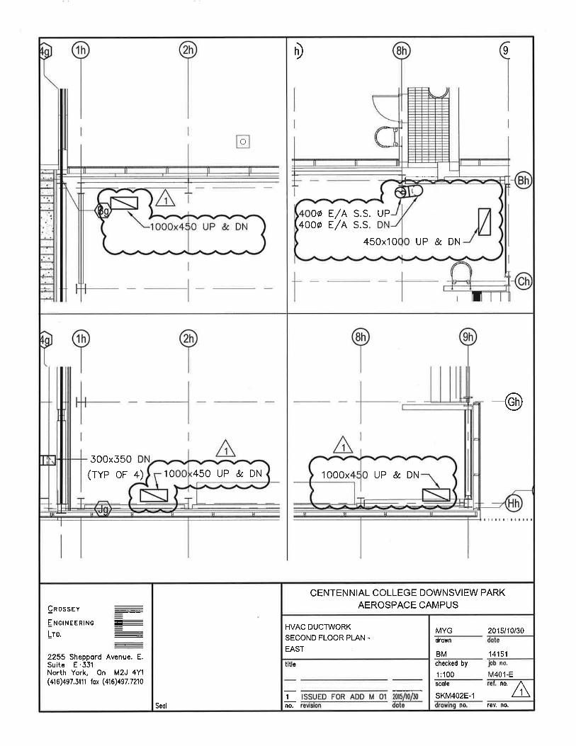
2.2 Refer to Dwg. M-402-E – HVAC Ductwork Second Floor Plan - East (not reissued, refer to attached sketch SKM402E-1).
1. Revise size of exhaust ductwork in room #160 Hangar A as shown.
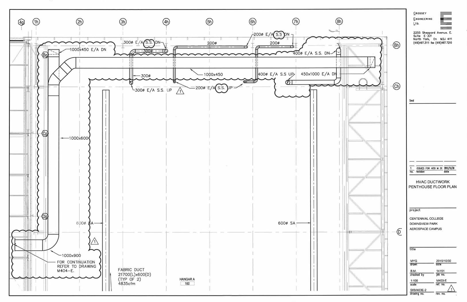
2.3 Refer to Dwg. M-403-E – HVAC Ductwork Penthouse Floor Plan (not reissued, refer to attached
sketches SKM403E-1 & SKM403E-2.) 1. Revise size of exhaust ductwork as shown.
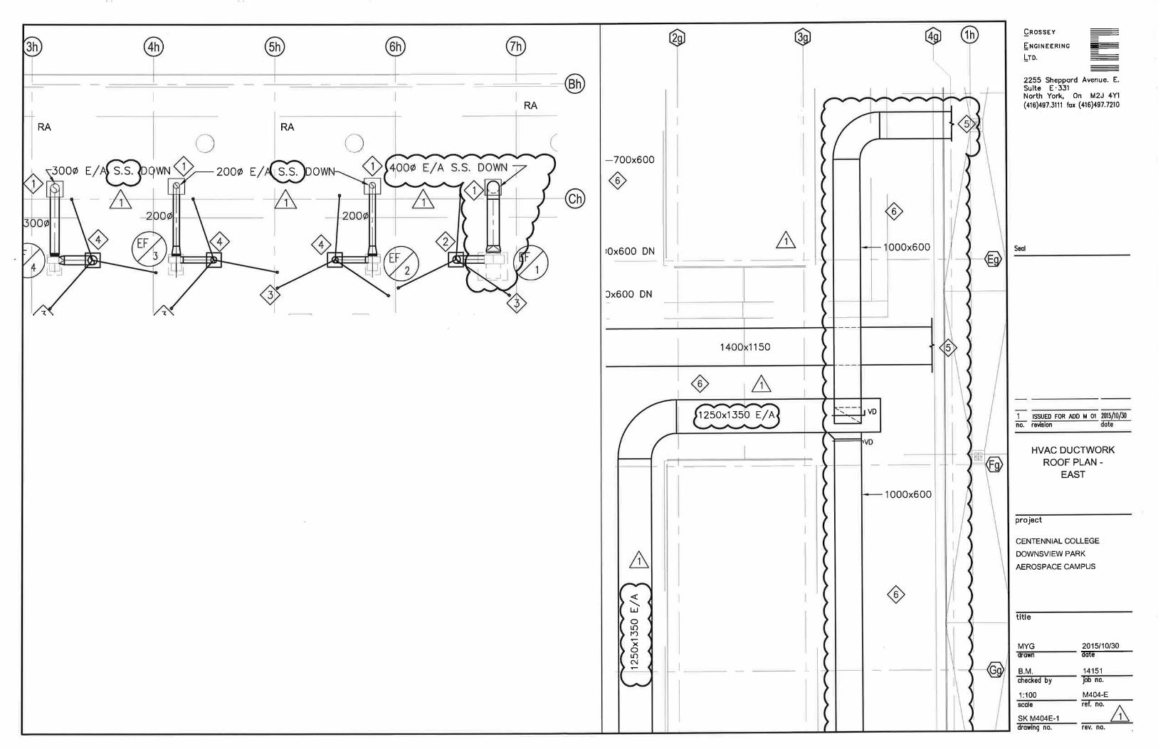
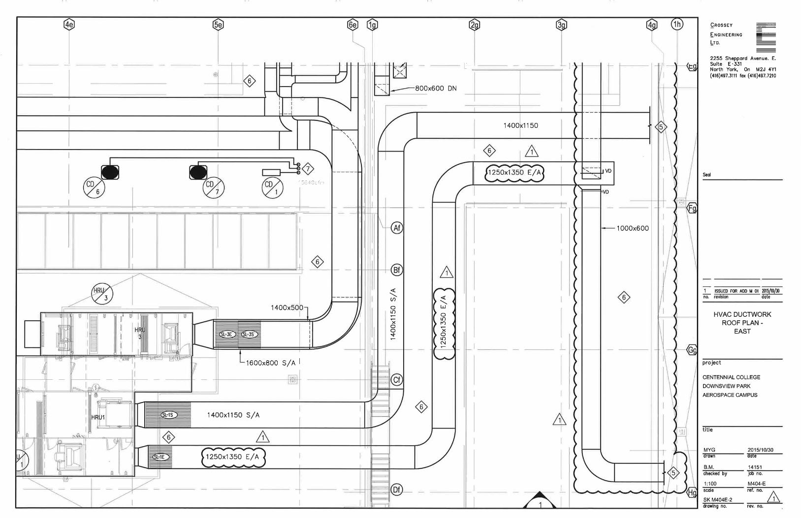
2.4 Refer to Dwg. M-404E– HVAC Ductwork Roof Plan- East (not reissued, refer to attached sketches
SKM404E-1 & SKM404E-2).
1. Revised size of exhaust ductwork as shown.
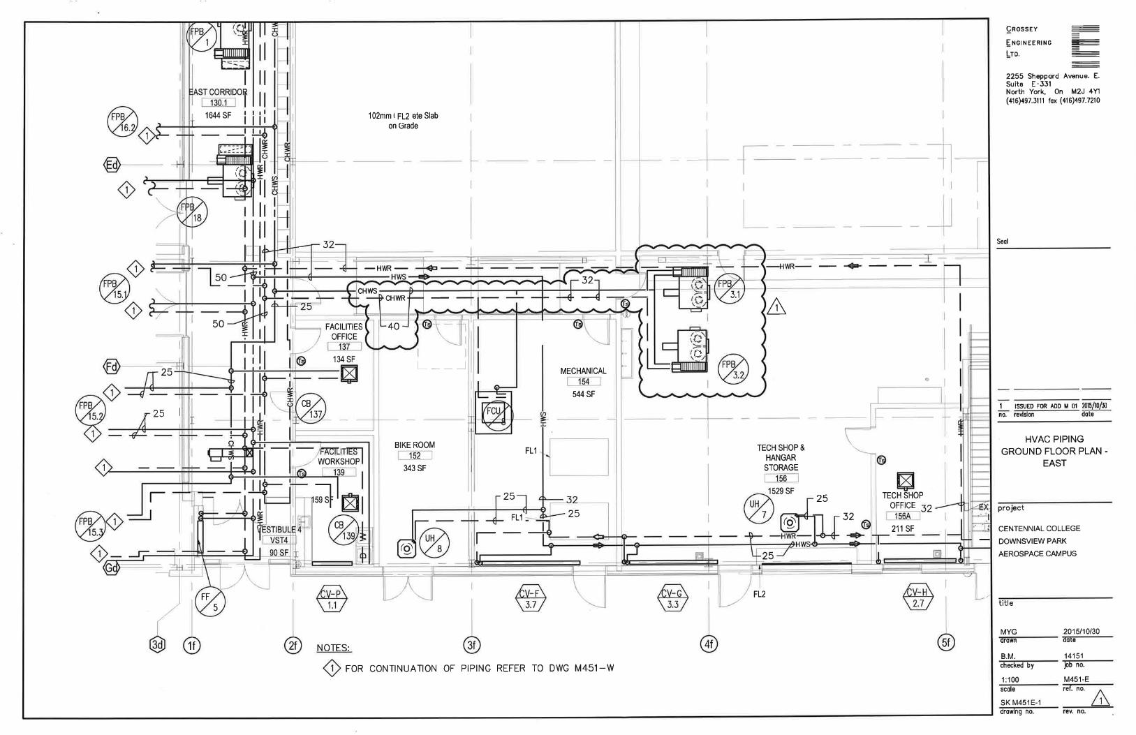
2.5 Refer to Dwg. M-451E –HVAC Piping Ground Floor Plan – East (not reissued, refer to attached sketch SKM451E-1).
1. Revise HVAC piping layout as shown.
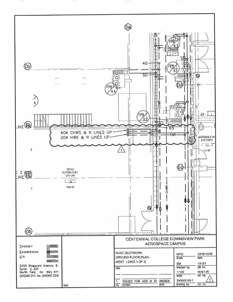
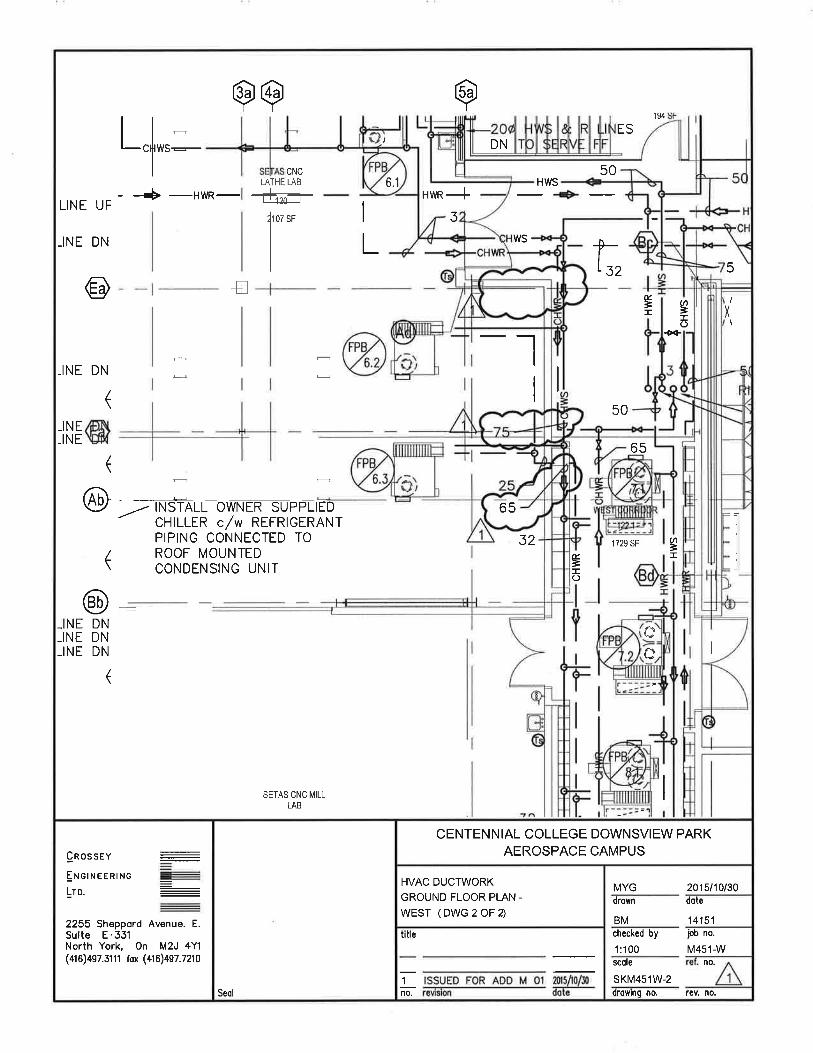
2.6 Refer to Dwg. M-451W –HVAC Piping Ground Floor Plan-West (not reissued, refer to attached
sketches SKM451W-1 & SKM451W-2).
1. Provide HVAC piping connections to FPB 4.1, 4.2, 4.3, 14.1, 14.2. 2. 3. Revise HVAC pipe sizes as shown.
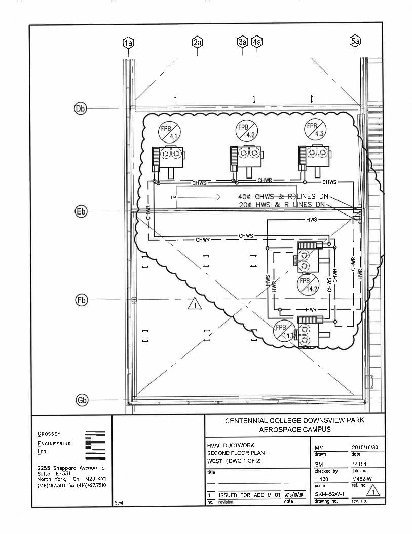
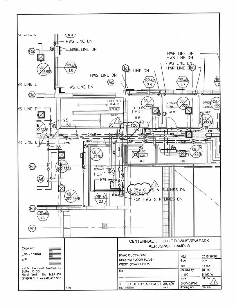
2.7 Refer to Dwg. M-452W – HVAC Piping Second Floor Plan-West (not reissued, refer to attached
sketches SKM452W-1 & SKM452W-2).
1. Add HVAC piping for FPB 4.1, 4.2, 4.3, 14.1, 14.2 .
2. Revise HVAC pipe sizes as shown.
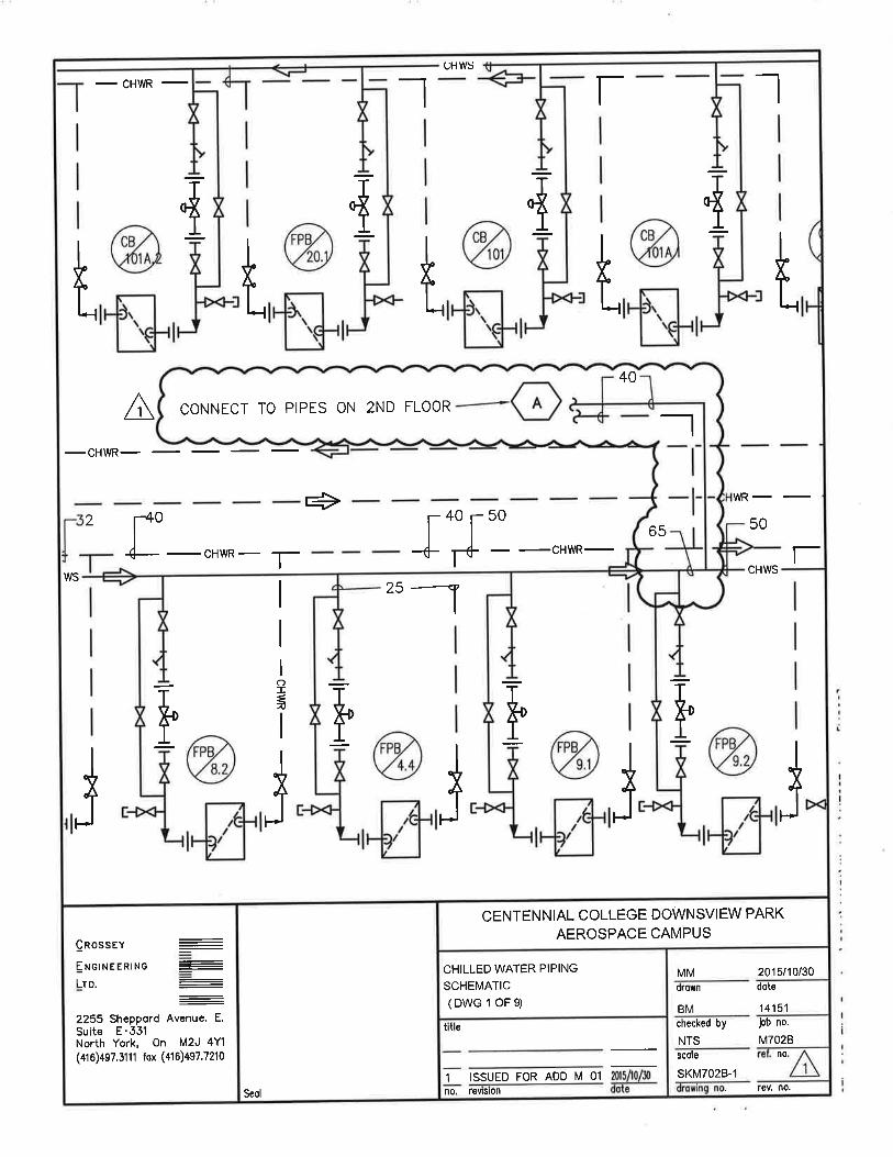
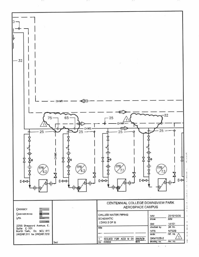
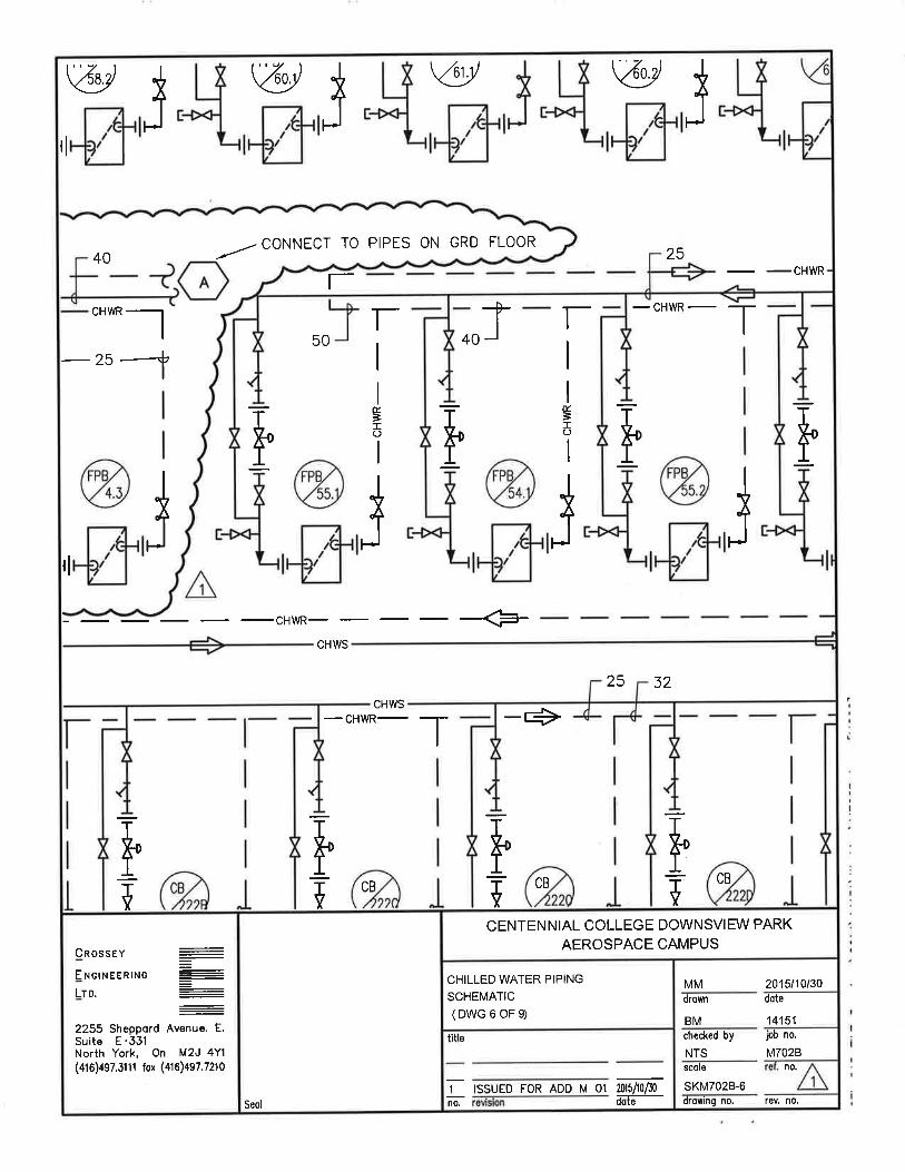
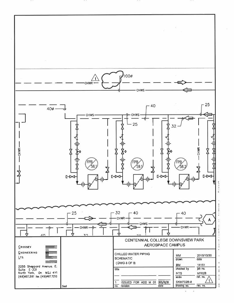
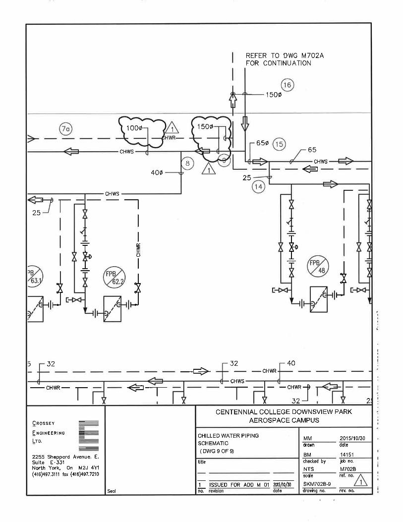
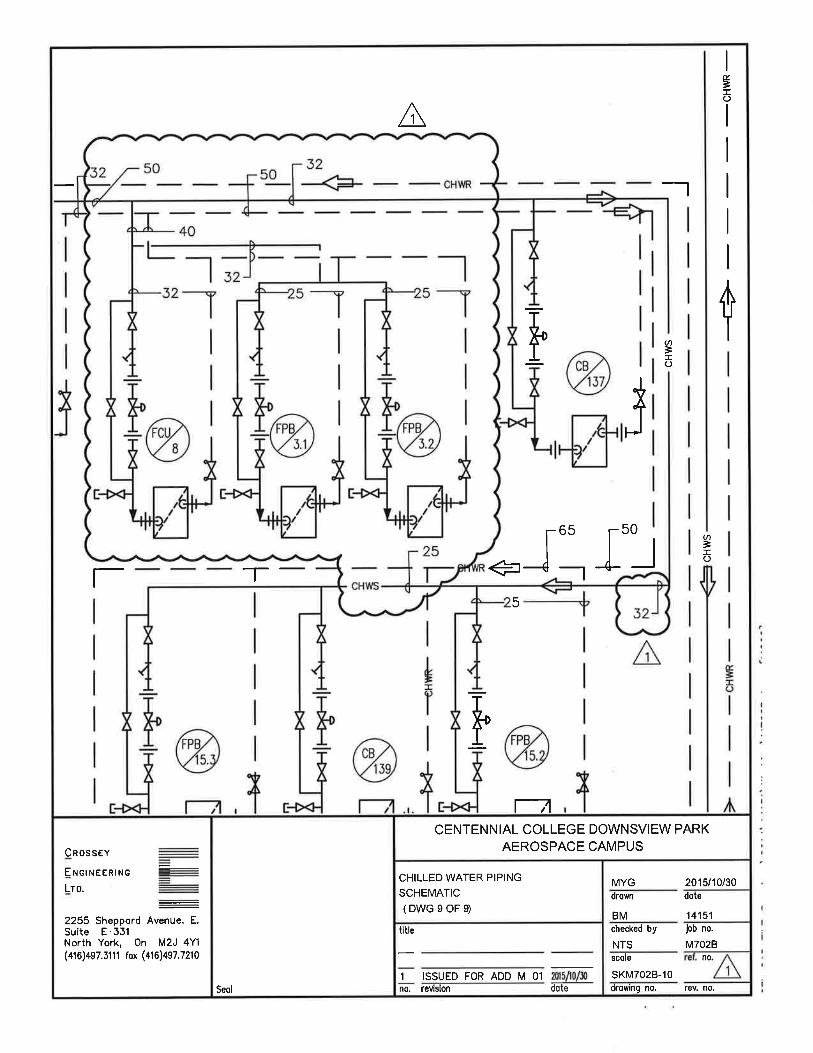
2.8 Refer to Dwg. M-702B– Chilled Water Schematic (not reissued, refer to attached sketches SKM702B-1, SKM702B-2, SKM702B-3, SKM702B-4, SKM702B-5, SKM702B-6, SKM702B-7, SKM702B-8, SKM702B-9, SKM702B-10).
Centennial College Downsview Park Aerospace Campus Addendum No. M-01 October 30, 2015 Page 3 of 3
Consulting Engineers Electrical, Mechanical, Lighting I:\PROJECTS\2014\14151-M\ADDENDUM\ADD M-01\ADD M-01.DOC
1. Revise HVAC chilled water piping and sizes as shown.
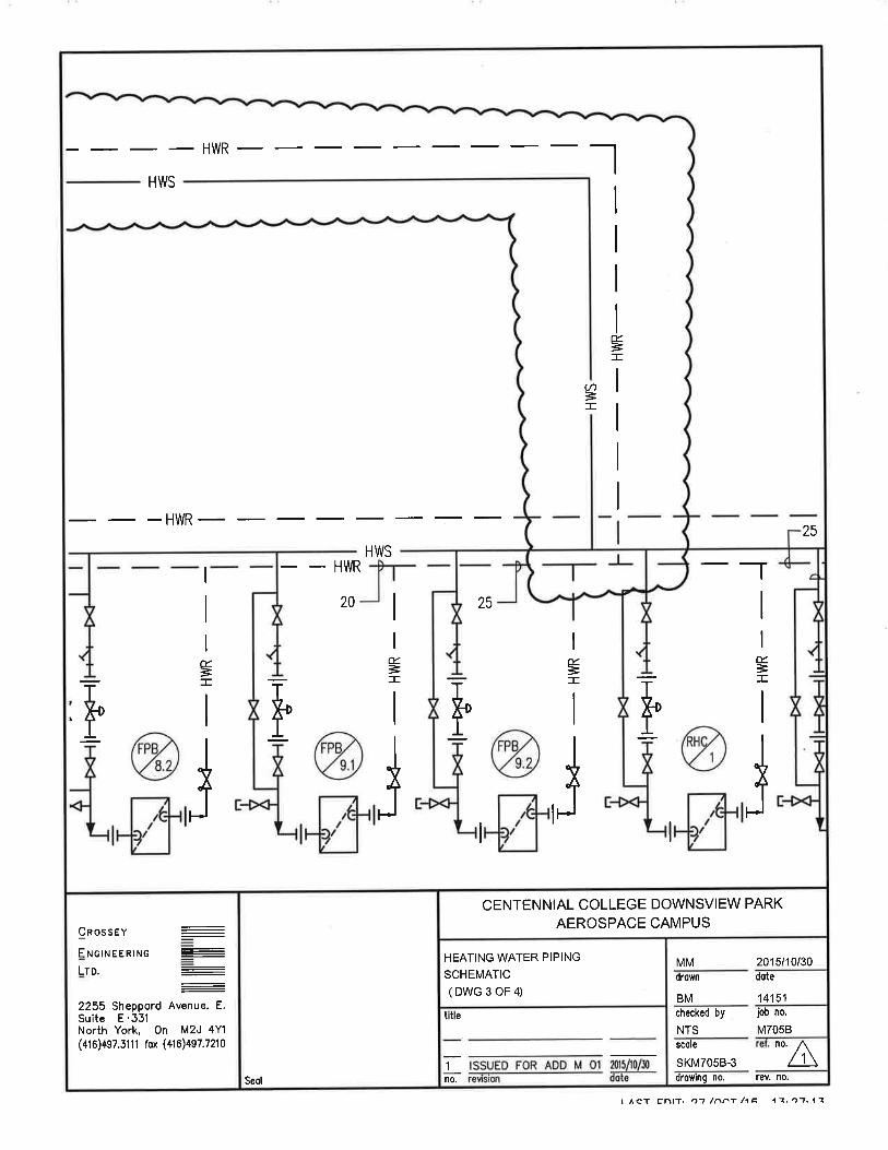
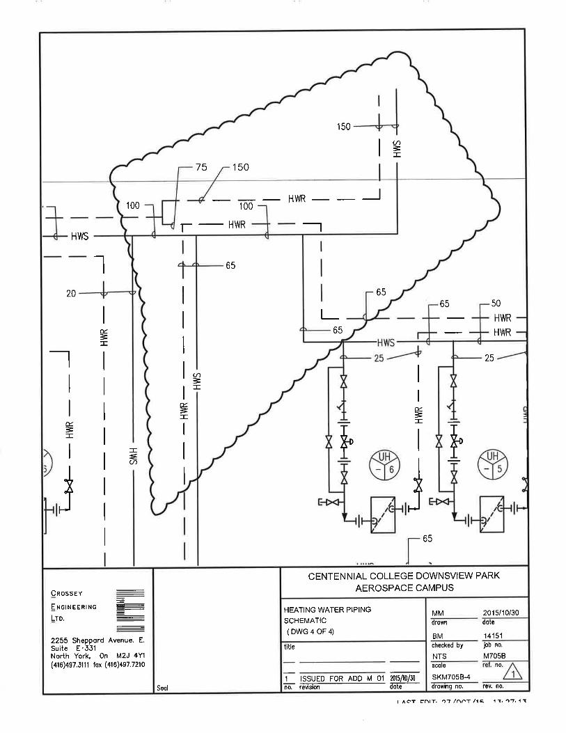
2.9 Refer to Dwg. M-705B – Hot Water Heating Schematic Dwg 1 of 2. (not reissued, refer to attached sketches SKM705B-1, SKM705B-2, SKM705B-3, SKM705B-4). 1. Revise HVAC hot water heating piping & sizes as shown.
TOTAL NUMBER OF PAGES: 33
END OF ADDENDUM NO. M-01
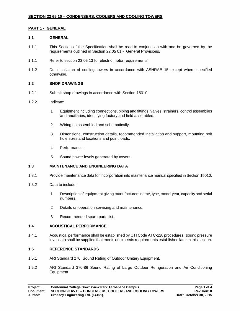
SECTION 23 65 10 – CONDENSERS, COOLERS AND COOLING TOWERS
Project: Centennial College Downsview Park Aerospace Campus Page 1 of 4 Document: SECTION 23 65 10 – CONDENSERS, COOLERS AND COOLING TOWERS Revision: 0 Author: Crossey Engineering Ltd. (14151) Date: October 30, 2015
PART 1 - GENERAL
1.1 GENERAL
1.1.1 This Section of the Specification shall be read in conjunction with and be governed by the requirements outlined in Section 22 05 01 - General Provisions.
1.1.1 Refer to section 23 05 13 for electric motor requirements.
1.1.2 Do installation of cooling towers in accordance with ASHRAE 15 except where specified otherwise.
1.2 SHOP DRAWINGS
1.2.1 Submit shop drawings in accordance with Section 15010.
1.2.2 Indicate:
.1 Equipment including connections, piping and fittings, valves, strainers, control assemblies and ancillaries, identifying factory and field assembled.
.2 Wiring as assembled and schematically.
.3 Dimensions, construction details, recommended installation and support, mounting bolt hole sizes and locations and point loads.
.4 Performance.
.5 Sound power levels generated by towers.
1.3 MAINTENANCE AND ENGINEERING DATA
1.3.1 Provide maintenance data for incorporation into maintenance manual specified in Section 15010.
1.3.2 Data to include:
.1 Description of equipment giving manufacturers name, type, model year, capacity and serial numbers.
.2 Details on operation servicing and maintenance.
.3 Recommended spare parts list.
1.4 ACOUSTICAL PERFORMANCE
1.4.1 Acoustical performance shall be established by CTI Code ATC-128 procedures. sound pressure level data shall be supplied that meets or exceeds requirements established later in this section.
1.5 REFERENCE STANDARDS
1.5.1 ARI Standard 270 Sound Rating of Outdoor Unitary Equipment.
1.5.2 ARI Standard 370-86 Sound Rating of Large Outdoor Refrigeration and Air Conditioning Equipment

SECTION 23 65 10 – CONDENSERS, COOLERS AND COOLING TOWERS
Project: Centennial College Downsview Park Aerospace Campus Page 2 of 4 Document: SECTION 23 65 10 – CONDENSERS, COOLERS AND COOLING TOWERS Revision: 0 Author: Crossey Engineering Ltd. (14151) Date: October 30, 2015
1.5.3 CTI Code ATC-128 Code for Measurement of Sound from Water-Cooling Towers
1.5.4 Refer to Section 220548 for additional requirements.
PART 2 - PRODUCTS
2.1 GENERAL
2.1.1 Provide as indicated two factory assembled forced draft low profile counterflow vertical discharge cooling tower.
2.1.2 Standard of Acceptance Forced Draft Towers: Baltimore, Evapco.
2.2 FORCED DRAFT TOWER
2.2.1 The cooling tower shall be factory-assembled, LOW PROFILE, counterflow, blow- through design Cooling tower with single side air entry. All moving parts factory mounted and aligned. All structural elements and steel panels shall be constructed of Z-700 Hot-Dip Galvanized steel, including the eliminators.
2.2.2 Cooling Tower capacity shall be in accordance with the schedule. Cooling Tower thermal performance shall be certified by the Cooling Tower Institute in accordance with CTI Certification Standard STD-201 or, lacking such certification a field acceptance test shall be conducted within the warranty period in accordance with CTI Acceptance Test Code ATC-105 by the Cooling Tower Institute or other qualified independent agency such as a certified agency of the Associated Air Balance Council (AABC). When a field required, the Cooling Tower submittal shall include performance curves in accordance with Section 11 of ATC-105. A manufacturer's guarantee, performance bond, or test by the manufacturer will not accepted as an alternative to CTI Certification or an independent field test.
2.2.3 Should the field performance prove the Tower's performance deficient, the Cooling Tower manufacture shall bear all costs necessary to correct the deficiency and shall reimburse the purchaser for any power increase required to meet the performance specification. The Towers shall be retested and certified after all deficiencies are corrected.
2.2.4 The pan section shall be constructed by heavy gauge Z-700 Hot-Dip Galvanized Steel panels utilizing double brakes flanges for maximum strength, rigidity and reliable sealing at water-tight joints. Standard pan accessories shall include large circular access doors, large area lift out strainer of anti vortexing design.
2.2.5 The fan shall be located in the dry air stream to provide greater reliability and ease of maintenance. Fan wheels are to be forwardly curved centrifugal squirrel-cage type and shall be statically and dynamically balanced and shall be mounted on a steel fan shaft supported by heavy-duty, self-aligning, relubricatable bearings with cast iron housings. Intermediate sleeve bearings will not be acceptable. Fan housings shall have curved inlet rings for efficient air entry. Fan wheels and housings shall be constructed of heavy gauge galvanized steel.
2.2.6 The fan housings shall be of split design to facilitate fan wheel and shaft removal. Towers not having split housing design must coordinate layout with the architect to allow space for fan shaft removal.
2.2.7 Motors shall be 1800 rpm T.E.F.C. ball bearing type with 1.15 service factor and shall be located at the base of the unit. The motors shall be mounted on a heavy-duty motor base, adjustable by means of a single threaded bolt-and-nut arrangement. The motors shall be suitable for outdoor service on 600 volt, 60 hertz, 3 phase electrical service.
SECTION 23 65 10 – CONDENSERS, COOLERS AND COOLING TOWERS
Project: Centennial College Downsview Park Aerospace Campus Page 3 of 4 Document: SECTION 23 65 10 – CONDENSERS, COOLERS AND COOLING TOWERS Revision: 0 Author: Crossey Engineering Ltd. (14151) Date: October 30, 2015
2.2.8 V-belt fan drive shall be sized for not less than 150% of motor nameplate horsepower. Drive and all moving parts shall be protected by removal Hot-Dip Galvanized screens and panels.
2.2.9 The heat transfer section shall include serpentine, Polyvinyl Chloride (PVC) Wet Deck surface below a spray-type water distribution system, all encased by 2-600 Hot-Dip Galvanized Steel panels. The Polyvinyl Chloride (PVC) sheets be impervious to rot, decay, fungus or biological attack and have a flame spread rating of 5 per ASTM Standard E84-09a. The surface shall be manufactured and performance tested by the Cooling Tower manufacturer to ensure single source responsibility and control of the final product.
2.2.10 Water shall be distributed evenly over the heat transfer section. The system shall consist of Schedule 40 PVC header and spray nozzles shall be held in place by snap-in rubber grommets, providing quick removal of individual spray nozzles or complete branches for cleaning or flushing. Screw-in nozzles will not be acceptable. Provide PVC to steel adapter at the point where external piping connects to the tower.
2.2.11 The eliminators shall be designed of PVC treated to resist ultra violet light and be removable in easily handled sections. They shall have a minimum of three changes in air direction with an air deceleration zone to direct discharge air away from the fans and limit drift loss to less than 0.002% of the total water circulated.
2.2.12 Electric Immersion Pan Heaters: The cooling Towers shall be provided with electric immersion pan heaters to prevent the condenser water from freezing when the units are inoperative. The heaters shall be sized to maintain the pan water temperature at plus 40o F. when the ambient air temperature is minus 20o F (-28.9 C).
2.2.13 Heater capacities shall be in accordance with the schedule. The heaters shall be tubular element construction and the contact terminals enclosed in a moisture proof terminal box. A 120 volt, moisture resistant temperature controller shall be included. A low water level cutout shall be provided to de-energize the heaters in the event the element is not fully submerged.
2.3 WATER LEVEL CONTROL
2.3.1 Supply and install a slow closing brass solenoid make up valve with large diameter polystyrene filled plastic float arranged for easy adjustment. Install in the make up water lines as shown on the drawings.
2.3.2 Water meter on make up water shall be electronic and shall be provided with a pulse output to allow for flow monitoring at the Building Automation System (BAS).
2.4 VARIABLE SPEED DRIVES, DISCONNECTS, WIRING
2.4.1 The capacity control for the tower shall be controlled by adjusting the speed of the motor with a variable frequency drive provided for each tower.
2.4.2 The BAS shall send a signal to the Variable Frequency Drive to speed up or slow down the fan.
2.4.3 Cooling tower manufacturer shall provide a control panel to house the starters for the pan heaters, necessary transformers, overloads, fuses, H-O-A's and pilot lights.
2.4.4 Do all power and control wiring between panels and towers. All contactors shall be NEMA rated. The Electrical Contractor shall provide a single power connection for the tower and pan heaters.
2.4.5 Provide a weatherproof disconnect for the pan heaters on the towers.

SECTION 23 65 10 – CONDENSERS, COOLERS AND COOLING TOWERS
Project: Centennial College Downsview Park Aerospace Campus Page 4 of 4 Document: SECTION 23 65 10 – CONDENSERS, COOLERS AND COOLING TOWERS Revision: 0 Author: Crossey Engineering Ltd. (14151) Date: October 30, 2015
2.4.6 Provide a variable frequency drive for each tower for capacity control. The variable frequency drive shall be located in a remote location within the building. Provide weatherproof disconnect for the power supply to the motor on the tower.
2.4.7 Drives shall be in accordance with Section 230510 of the specification and all variable frequency drives on the project shall be by the same Manufacturer.
2.4.8 The Mechanical Contractor shall provide all wiring required between the cooling tower control panel and the variable frequency drives and the towers.
3 EXECUTION
3.1 GENERAL
3.1.1 Units to be installed as indicated and to manufacturers recommendations, ensuring adequate clearances for servicing and maintenance.
3.1.2 Ensure manufacturers field service representative approves installation and is present to supervise start up and to instruct operators.
3.1.3 Provide control point sensing and wiring to complete control system installation. Wiring methods shall be as specified in Division 26. Pick up power wiring from local panel in room as designated on site.
3.1.4 Provide structural I-beam as shown on drawings to support tower above the main isolators. I beam shall be galvanized coated.
END OF SECTION