
Solgeo S.r.l. Via Pastrengo 9 24068 Seriate (BG) Italy ...sisplgroup.com/doc/Presentation of Sol...
39
Solgeo S.r.l. Via Pastrengo 9 24068 Seriate (BG) Italy Phone +39 035 4520075 Fax +39 035 4523705 www.solgeo.it e_mail [email protected]
Transcript of Solgeo S.r.l. Via Pastrengo 9 24068 Seriate (BG) Italy ...sisplgroup.com/doc/Presentation of Sol...

Solgeo S.r.l.
Via Pastrengo 9
24068 Seriate (BG) Italy
Phone +39 035 4520075
Fax +39 035 4523705
www.solgeo.it e_mail [email protected]

SolGeo‘s main Business ActivitiesSolGeo s main Business Activities
SeismicGeophysical Services
and TomographyTomography
D H l3rd Party
Geo-Radar
Down Hole &
Cross Hole
equipment

SOLGEO’s Main Focus in Geophysical Surveys
is structured along 33 distinctivee offerings:is structured along 3 distinctive offerings:
– engineered & specialized ProductsDigital multi-channels recorders
f– SServices corroborated by the use of SolGeo’s proprietary sensors
manyfold Geophysical Surveys y p y y
– Advice & Consulting Servicesmulti-annual expertise
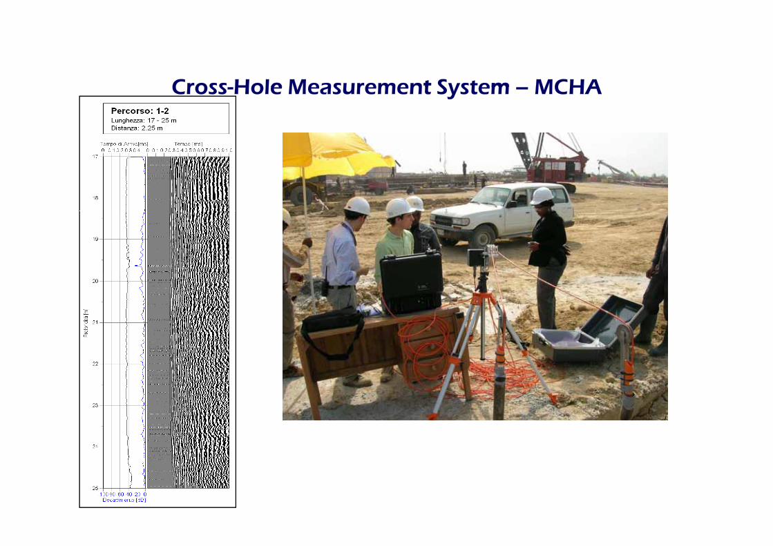
Cross Holee Measurementt Systemm MCHACross-Hole Measurement System – MCHA

Cross-Hole Measurement System –MCHAMCHA
Multichannel Cross-Hole Analyzer performing simultaneously cross-hole measurements along three paths.
The System can also be used for sonic and ultra-sonic investigations in concrete and masonry.
Thh SS lii hh NN The System complies to the Norms: ASTM D6760-02 and UNI 9524

MCHA – key benefits
� Highly powerful Pulse-Transmitter (>1.6kV) allowing measurements in foundations rods > 3m in diameter.
� The 16 bit sampling guarantees high quality of data.
� Performing simultaneously cross-hole measurements l th thalong three paths.
� Shortening ,where applicable, the time of measurement by 2/3./
� Preamplified sensor allows tests at any depth
� Encoder allows easy handling of the measurement’s
� All measurement data and graphics of the signal are stored in a database, allowing thus a „post process“ -analysis and -management of the stored profileanalysis and management of the stored profile information’s.
� The System can be used for sonic and ultra-sonic investigations of concrete and masonry.

MCHA – key benefits
� Pulse echo test and Low strain method ( PIT test ) with optional kit.
� Sonic log test with optional probe.
� Special cable with internal kevlar and high resistance .
� Internal battery for 8 hours of operation and external battery auto cable.
� P t A i t t d t di tl i S l l b i� Prompt Assistant and support directly in Solgeo lab in Bergamo Italy.
� All parts made in Italy by Solgeo� All parts made in Italy by Solgeo.
� Training in site by expert technicians

MCHA – key benefits
Pulse-Transmitter >1.6kV allows for diameters >3 mt.
Simultaneous measurement along three paths.
Di hi t dDiagraphies are presented next to each-other.

MCHA – key benefitsyCustomized Measurements Report

MCHA – components: C t ll U itCentral Unit
•2 x A/D 16-bit channels.
•Gain: software controlled (10x to 10240x).
•Sampling frequency from 1kHz up to 2MHz.
•Buffer of 32000 samples.
•Trigger internal/external ,softwaree selectedsoftware selected.
•PC I/O: Ethernet 10/100.
B ttt b ff d•Battery buffered
•IP67 Heavy duty case

MCHA – components:Encoder
The Encoder

MCHA – components:EncoderEncoder
• Buttons:� UP� DOWN� DOWN� PRESET
• Led:� Up – the sensors are correctly
diascending� Down – the sensors are descending� Trigger – the transmitter is emitting on
average every 2cm (default setting) a high frequency signalsetting) a high frequency signalalong the ascension path.
� Stand-by – standby condition of the system
� High speed – Warning: the sensor‘s ascension speed is to highascension speed is to high. The system stalls and the sensors must be lowered to the level of which the high speed was detected. The System senses automaticallythe various levels of intervention.

MCHA – components:SSensors
•Piezoelctric Transducers.
•Transmitter:1.6kV @80kHz.
•Receiver: 80kHz , pre-amplified.
•Transmitter/Receiver: 1 6kVV @@ 80kH ( lifi d)1.6kV @ 80kHz. (pre-amplified)
•Diameter - 28 mm.
•Length - 175 mm.
•Weight - 0.420 kg

MCHA – components: C bll llCable rolls
•Standard length 60 mt.
•Graduationn withh aa meter stepp •Graduation with a meter-step.
•Kevlar reinforced cables.

MCHA – components: T i dTripod
•Light metal
•Suitable for field operation

MCHA – components:S ftt MCH iSoftware – MCH-sonic
•High-speedd communicationn interfacee betweenn thee •High-speed communication interface between the PC and the Central Unit based on the IP protocol.
•Encoder communication package.p g
•Data Acquisition, Storage and Visualization.
•Diagraphy presentation.
•Analysiss off Firstt Breakk Timee andd Energyy Decay•Analysis of First Break Time and Energy Decay
•Report Generator

MCHSonic – Data Acquisition Panel The Acquisition Panel is driven by the attached Central Unit MCH
Selection buttons for Gain/Filters/Deoffset Sampling Settings
Acquisition:encoder driven
Gain settings for every single path Monitor = no acquisition
Menu driven setting of Gain- and Filter-Values for every single measurement path.
Menu selection of either one or three measurement paths and pertinent sampling settings with respect to frequency, time and sample quantity.
Offsett compensationn provisionn forr everyy measurementt path.Offset compensation provision for every measurement path.

MCHSonic – Data Visualization The size of the Visualization Window is determined by the Amplitude (V/div) and by the Time-Period (my/div) selected.
Shows the complete Signal

MCHSonic – Encoder Control PanelThe Encoder Control Panel allows setting up the Encoder parameters with respect to starting-point and the ending-point of the depth of measurement and the interval-step between two contiguos measurementscontiguos measurements.
One measurement every 2 cm. Considering 10 mt of depth, the total number of possible measurements is 10 x 50 = 500.
Actual depth where the transducer is..
Lowest depth of the measurement path.

MCHSonic – Diagraphy The Diagraphy, a diagram of variable intensity, shows for every measurement at a specific depth, the modulation of the amplitude and phase of the acquisition signal as a function of the traversed material
diiagraphy
Colour-barselection
material.
Actual depth where the depth pointer is positionned
Colour-barbenchmarks
is positionned.In this example the measurements used for diagraphy were from -14.2mt to -0.5mt.The measurements interval-steps annot be seen on this presentation,
“but will be presented in the “Report di Misura” report.

MCHSonicc – Analysiss off timee off MCHSonic Analysis of time of First Break and Energy decay dataThe Analysis of First Break and Energy decay is used to locate y gy ydiscontinuities, e.g. faults or even cavities in the concrete object under exam.
The identification of the time of First Break is based on the signal’s trespassing of a defined amplitude thresholdtrespassing of a defined amplitude threshold.
By varying a set of definable parameters the determination of the time of First Break can be refined. A further refinement can be obtained by selecting the “ Use back-time search algorithm” parameter. In this case the software will automatically “backwards” compute the intersection of the measured curve with the x-axes before the threshold level was triggered.

MCHSonic – Measurements ReportThe Measurements Report can be plotted for one to three Diagraphies, together with the graphic of time of first break and of the correspondent energy absorption.
A customized Header including company‘s logo can be defined.

MCHA – key benefitsyUse of the MCHA for
sonic and ultra-sonic investigations i t din concrete and masonry
RXTX
TX

MCHA – key benefitsUse of the MCHA for sonic and ultra sonicUse of the MCHA for sonic and ultra-sonic
investigations in concrete and masonry
Setup for ultrasonic measurements:
R X
TX
direct
indirectTX RX
di tTX
RX
non-direct

MCHA – key benefitsUse of the MCHA for sonic and ultra-sonicUse of the MCHA for sonic and ultra sonic investigations in concrete and masonry:
Tomography of measurements
RXTX
RXTX
Application Software
Tomography

MCHA – key benefitsUse of the MCHA for sonic and ultra-sonicUse of the MCHA for sonic and ultra sonic
investigations in concrete and masonry
Transducers-Sensors:
A)- piezoelectric Receiver (internally pre-amplified, 20dB, 10x)
55kHz res freq (optional 20 80kHz)55kHz res. freq. (optional 20-80kHz)

(CMS transducer)
Transducers-Sensors:B)- piezoelectric Transmitter with adjustable transmission pulse (up to 1.6kV)
T itt S ’ R t P h b ttTransmitter Sensor’s Remote Push-button: The push-button on the transmitter allows the operator the handling from a
“remote” position of the freeze - and of the store - function.
If the push-button on the transmitter is pressed once, the signal acquisition h PDA i h f i h “ h d ”on the PDA switches from continuous to the “one shot mode”.
If the push-button is press-touched and hold for at least 3 sec, than when released, the data storing function is performed.

(CMS transducer)
Transducers-Sensors:
C)- piezoelectric Hammer-Transducer for low frequency / high energy signalsC) piezoelectric Hammer Transducer for low frequency / high energy signals

CMCHAUse of the MCHA for Pulse echo test and Low Strain
MethodMethod
Pile Processing Software V.1.12

• Introduction
• Metod PEM
• Metod TRM (FD/TD)Metod TRM (FD/TD)
• Pile Processing Software
• Example

Pile Processing Software(start window)(start window)

Pile Processing Software(setup parameters)(setup parameters)

Pile Processing Software

Pile Processing Software(report 1/2)(report 1/2)

Pile Processing Software(report 2/2)(report 2/2)

Example 1

Example 1

Example 2

Example 2


![LS Simple™ Structured Cabling System Supply Record · 2/Page [ ] Ospedale Bolognini •Site : Seriate, Lombardia, Italy •Solution : Cat 6 Solution & OM3 FO •Remarks : - Great](https://static.fdocuments.in/doc/165x107/5fd1009421fe4b50c20377f1/ls-simplea-structured-cabling-system-supply-2page-ospedale-bolognini-asite.jpg)
