Solenoid Valves - SEALL s.r.o. · PDF fileSectional drawings of solenoid valve types Sizing...
107
Cat.: GP/GB May 2002 Solenoid Valves for application in: • AUTOMATION • HIGH TEMPERATURE - STEAM • HEATING Controls Climate & Industrial
-
Upload
nguyentram -
Category
Documents
-
view
222 -
download
2
Transcript of Solenoid Valves - SEALL s.r.o. · PDF fileSectional drawings of solenoid valve types Sizing...
Cat.: GP/GBMay 2002
Solenoid Valves for application in:• AUTOMATION• HIGH TEMPERATURE - STEAM• HEATING
ControlsClimate & Industrial
2/2 N.C. Direct operated
2/2 N.C. Direct operated, 90’ fittings
2/2 N.O. Direct operated, reversed seat
2/2 N.O. Direct operated.
2/2 N.C. Diaphragm pilot operated, lateral pilot
2/2 N.C. Diaphragm pilot operated,central pilot
2/2 N.C. Combined operation, hung diaphragm
2/2 N.O. Diaphr. pilot operated,lateral pilot
3/2 N.C. Direct operated
3/2 N.C. Direct operated, flanged body
3/2 Univers. Direct operated
Parker Hannifin S.p.A.via E. Fermi, 520060 Gessate (Milano) - Italy
1
Climate& Industrial Controls
Technical informationIndex for identification of the type/series of valve required
Once the series required has been identified:1: look up on pg. 3 the catalogue page corresponding to the series of solenoid valves;2: go to the contents page of the section corresponding to the type of application (the second in the section):
the section is indicated by the background colour of the box where the required series is identified.In this section you will find all the specific technical information on the double page of the series required.
Column indicating the operation of the various series of solenoid valves
Fitting G [ ” ] or Rp, R where specified
PortingRest. Control / Operation / Fittingsposit.
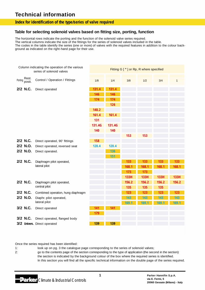
Table for selecting solenoid valves based on fitting size, porting, function
The horizontal rows indicate the porting and the function of the solenoid valve series required.The vertical columns indicate the size of the fittings for the series of solenoid valves included in the table.The codes in the table identify the series (one or more) of valves with the required features in addition to the colour back-ground as indicated on the right-hand page for their use.
1/8 1/4 3/8 1/2 3/4 1
131.4 131.4146 146174 174
126140.2161.4 161.4131
131.4G 131.4G140 140
153 153158
120.4 120.4136151
133 133 133 133168.1 168.1 168.1 168.1173 173
133H 133H 133H 133H156.2 156.2 156.2 156.2135 135 135123 123 123 123143 143 143 143
169.1 169.1 169.1 169.1141 141179
139 139
Parker Hannifin S.p.A.via E. Fermi, 520060 Gessate (Milano) - Italy
2
Climate& Industrial Controls
Technical informationIndex for identification of the type/series of valve required
2/2 N.C. Direct operated
2/2 N.C. Direct operated, 90’ fittings
2/2 N.O. Direct operated, reversed seat
2/2 N.O. Direct operated.
2/2 N.C. Diaphragm pilot operated, lateral pilot
2/2 N.C. Diaphragm pilot operated,central pilot
2/2 N.C. Combined operation, hung diaphragm
2/2 N.O. Diaphr. pilot operated,lateral pilot
3/2 N.C. Direct operated
3/2 N.C. Direct operated, flanged body
3/2 Univers. Direct operated
Column indicating the operation of the various series of solenoid valves
PortingRest. Control / Operation / Fittingsposit.
Fitting G [ ” ] or Rp, R where specified
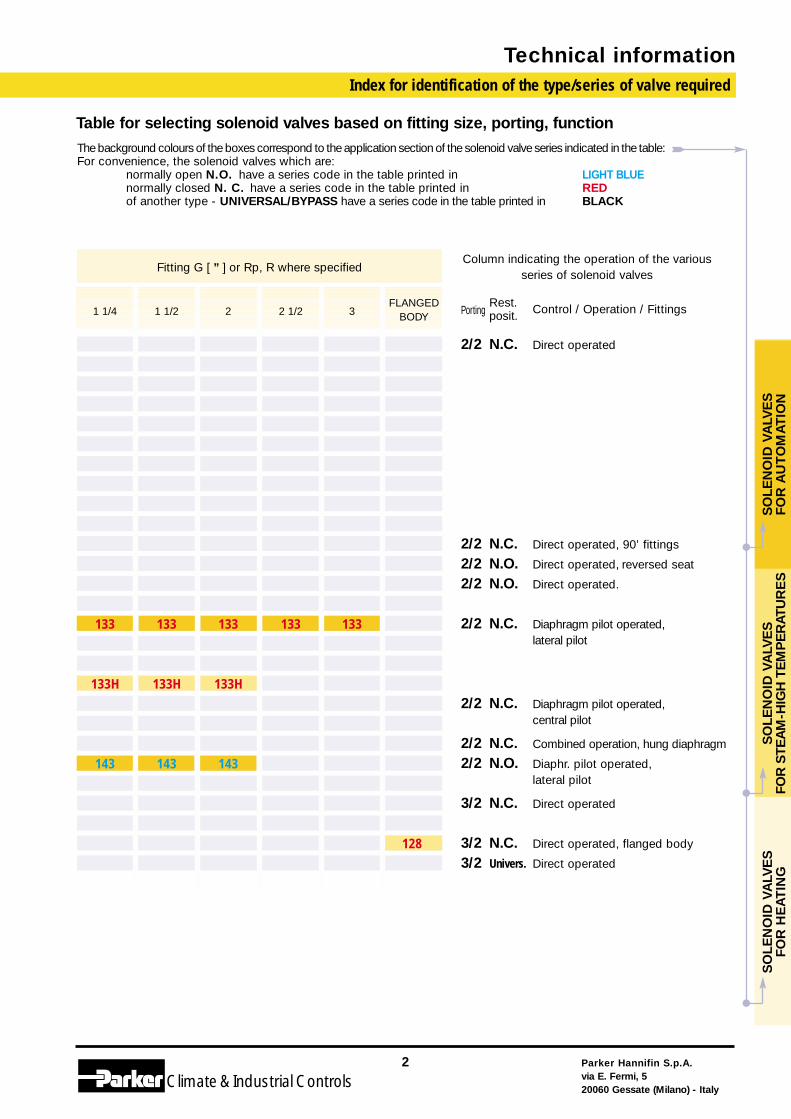
1 1/4 1 1/2 2 2 1/2 3
133 133 133 133 133
133H 133H 133H
143 143 143
128
Table for selecting solenoid valves based on fitting size, porting, function
SO
LEN
OID
VA
LVE
S
FOR
AU
TO
MA
TIO
NS
OLE
NO
ID V
ALV
ES
FO
R S
TEA
M-H
IGH
TE
MP
ER
ATU
RE
SS
OLE
NO
ID V
ALV
ES
FO
R H
EA
TIN
G
FLANGEDBODY
The background colours of the boxes correspond to the application section of the solenoid valve series indicated in the table:For convenience, the solenoid valves which are:
normally open N.O. have a series code in the table printed in LIGHT BLUEnormally closed N. C. have a series code in the table printed in REDof another type - UNIVERSAL/BYPASS have a series code in the table printed in BLACK
Parker Hannifin S.p.A.via E. Fermi, 520060 Gessate (Milano) - Italy
3
Climate& Industrial Controls
Technical information
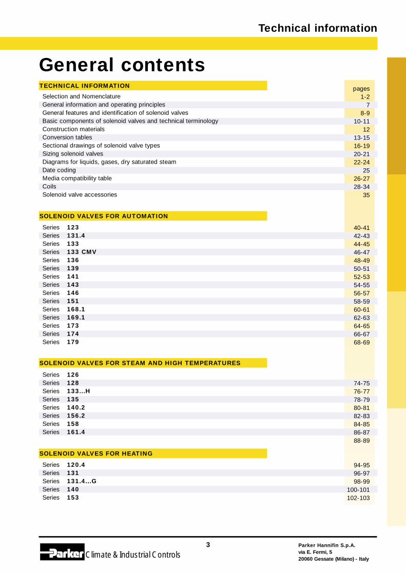
General contentspages
1-27
8-910-11
1213-1516-1920-2122-24
2526-2728-34
35
40-4142-4344-4546-4748-4950-5152-5354-5556-5758-5960-6162-6364-6566-6768-69
74-7576-7778-7980-8182-8384-8586-8788-89
94-9596-9798-99
100-101102-103
Selection and Nomenclature General information and operating principlesGeneral features and identification of solenoid valvesBasic components of solenoid valves and technical terminologyConstruction materialsConversion tablesSectional drawings of solenoid valve typesSizing solenoid valvesDiagrams for liquids, gases, dry saturated steamDate codingMedia compatibility tableCoilsSolenoid valve accessories
Series 123Series 131.4Series 133Series 133 CMVSeries 136Series 139Series 141Series 143Series 146Series 151Series 168.1Series 169.1Series 173Series 174Series 179
Series 126Series 128Series 133...HSeries 135Series 140.2Series 156.2Series 158Series 161.4
Series 120.4Series 131Series 131.4...GSeries 140Series 153
TECHNICAL INFORMATION
SOLENOID VALVES FOR AUTOMATION
SOLENOID VALVES FOR STEAM AND HIGH TEMPERATURES
SOLENOID VALVES FOR HEATING
Technical information
Parker Hannifin S.p.A.via E. Fermi, 520060 Gessate (Milano) - Italy
4
Climate& Industrial Controls
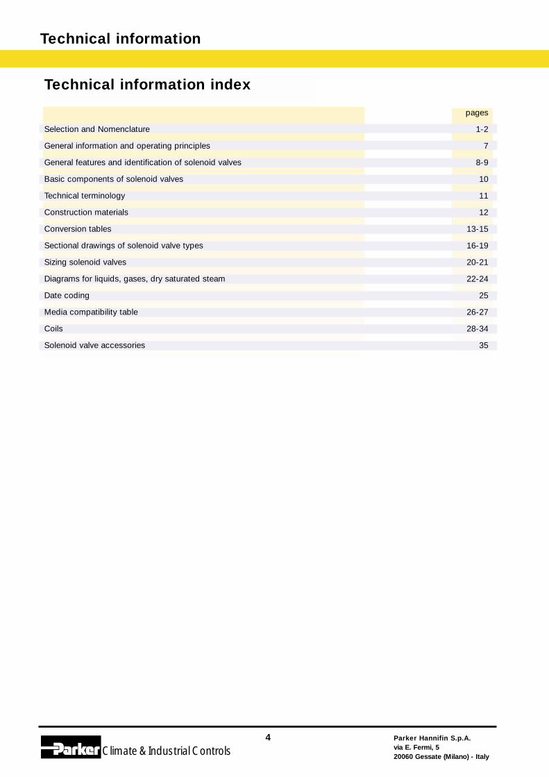
Selection and Nomenclature
General information and operating principles
General features and identification of solenoid valves
Basic components of solenoid valves
Technical terminology
Construction materials
Conversion tables
Sectional drawings of solenoid valve types
Sizing solenoid valves
Diagrams for liquids, gases, dry saturated steam
Date coding
Media compatibility table
Coils
Solenoid valve accessories
Technical information index
pages
1-2
7
8-9
10
11
12
13-15
16-19
20-21
22-24
25
26-27
28-34
35
Parker Hannifin S.p.A.via E. Fermi, 520060 Gessate (Milano) - Italy
5
Climate& Industrial Controls
Technical informationContents
Technical Information

Technical information
Parker Hannifin S.p.A.via E. Fermi, 520060 Gessate (Milano) - Italy
6
Climate& Industrial Controls
General information and operating principles
Parker Hannifin S.p.A.via E. Fermi, 520060 Gessate (Milano) - Italy
7
Climate& Industrial Controls
Technical information
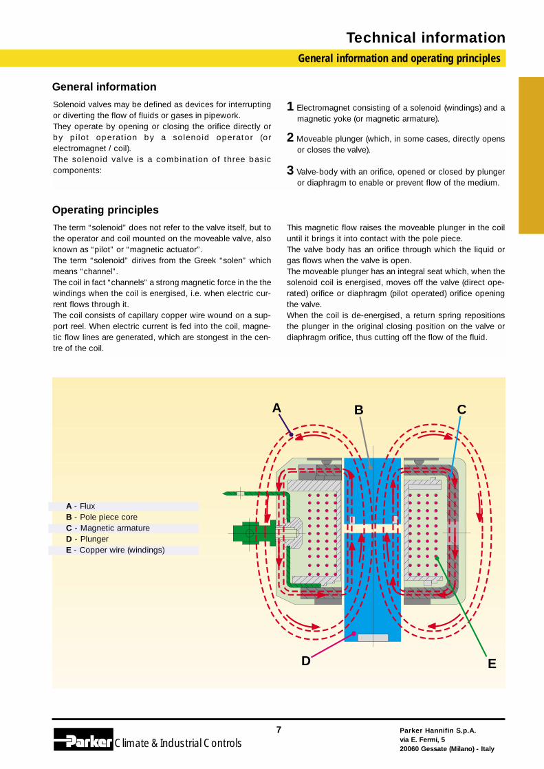
General information
Solenoid valves may be defined as devices for interruptingor diverting the flow of fluids or gases in pipework.They operate by opening or closing the orifice directly orby pi lot operation by a solenoid operator (orelectromagnet / coil).The solenoid valve is a combination of three basiccomponents:
1 Electromagnet consisting of a solenoid (windings) and amagnetic yoke (or magnetic armature).
2 Moveable plunger (which, in some cases, directly opensor closes the valve).
3 Valve-body with an orifice, opened or closed by plungeror diaphragm to enable or prevent flow of the medium.
Operating principles
The term “solenoid” does not refer to the valve itself, but tothe operator and coil mounted on the moveable valve, alsoknown as “pilot” or “magnetic actuator”. The term “solenoid” dirives from the Greek “solen” whichmeans “channel”. The coil in fact “channels” a strong magnetic force in the thewindings when the coil is energised, i.e. when electric cur-rent flows through it.The coil consists of capillary copper wire wound on a sup-port reel. When electric current is fed into the coil, magne-tic flow lines are generated, which are stongest in the cen-tre of the coil.
This magnetic flow raises the moveable plunger in the coiluntil it brings it into contact with the pole piece. The valve body has an orifice through which the liquid orgas flows when the valve is open.The moveable plunger has an integral seat which, when thesolenoid coil is energised, moves off the valve (direct ope-rated) orifice or diaphragm (pilot operated) orifice openingthe valve. When the coil is de-energised, a return spring repositionsthe plunger in the original closing position on the valve ordiaphragm orifice, thus cutting off the flow of the fluid.
A B C
D E
A - FluxB - Pole piece coreC - Magnetic armatureD - PlungerE - Copper wire (windings)
Technical informationGeneral features - Types of solenoid valves
Parker Hannifin S.p.A.via E. Fermi, 520060 Gessate (Milano) - Italy
8
Climate& Industrial Controls
General features
This section describes the operation of the solenoid val-ves, versions and types available, selecton tables andgraphs, basic components, common technical termino-logy, conversion tables for solenoid valves in variousunits of measurement.
Principles of operation
In compact solenoid valves, the solenoid coil is mounteddirectly on the enclosing tube, sealed and integral with thevalve body. The moveable plunger is free to move in theenclosing tube and is normally held in position by a thrust(or return) spring.When the solenoid coil is energised, the plunger isattracted by the effect of the magnetic field and the seat,integral with the plunger, opens (or closes) the valve or thevalve pilot.
Solenoid valves/versions available
a) direct actingThe moveable plunger with integral seat, by the action ofthe solenoid coil, opens or closes the orifice depending onwhether current is supplied to the solenoid (energised orde-energised solenoid) or not.In this direct operated design the coil itself supplies all theenergy required to move the plunger and seat. Operationdoes not therefore depend on the pressure of the fluid orthe flow rate.The solenoid valve can operate from 0 pressure differenceup to the value indicated in the tables.
b) Pilot operated(servocontrolled or diaphragm pilot operated):These solenoid valves are fitted with a pilot seat, controlledby the solenoid coil and a diaphragm which closes themain orifice of the valve, using the fluid pressure foroperation. When the solenoid is energised, the core opensthe pilot seat to allow the pressure on the upper part of thediaphragm to flow to the outlet of the valve body. Thus apressure imbalance is created on the diaphragm, raising itand fully opening the valve orifice.When the solenoid is de-energised, the pilot seat closesand the pressure, passing through an “equaliser” hole, isrestored above the diaphragm, thus closing the valve.Operation depends on a pressure difference betweenupstream and downstream of the solenoid valve whichequals the force required for moving the diaphragm orkeeping it tight on the main orifice. This value, indicated inthe tables, is known as “minimum operating pressure”.
c) Combined operation In this design the moveable plunger is physically connectedto the diaphragm in which the pilot orifice is located.The attraction of the plunger thus opens the pilot orifice andthe pressure lifts the diaphragm which is further moved bythe plunger during its opening stroke (assisted lift). Thus bydirect operation (plunger) and pilot operation (diaphragm) itis possible to achieve full flow even at low pressures andnormal operation (and shut off) even at 0 pressure.
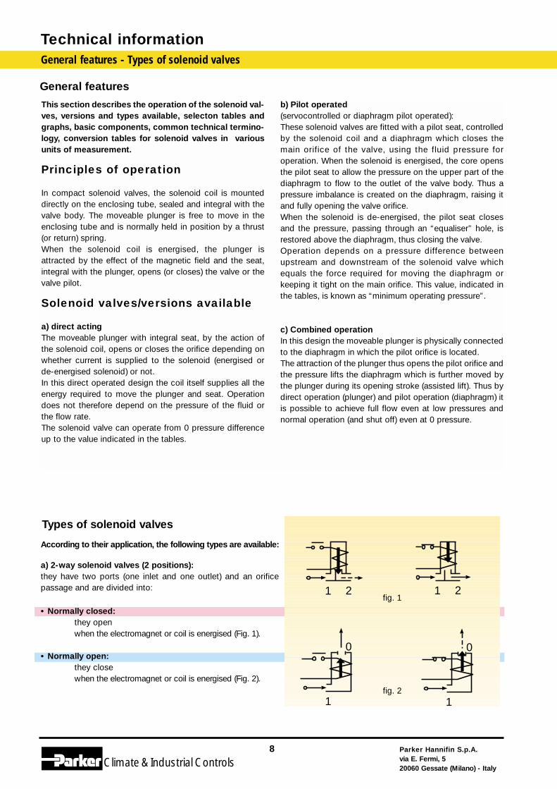
Types of solenoid valves
21 21
1
0
1
0
fig. 1
fig. 2
According to their application, the following types are available:
a) 2-way solenoid valves (2 positions):they have two ports (one inlet and one outlet) and an orificepassage and are divided into:
• Normally closed:they open when the electromagnet or coil is energised (Fig. 1).
• Normally open:they closewhen the electromagnet or coil is energised (Fig. 2).
Classification of the solenoid valves contd.
Parker Hannifin S.p.A.via E. Fermi, 520060 Gessate (Milano) - Italy
9
Climate& Industrial Controls
Technical information
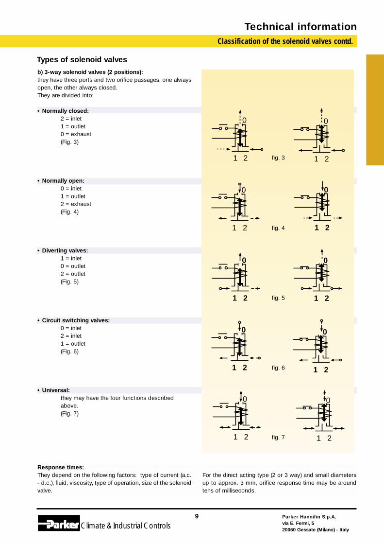
b) 3-way solenoid valves (2 positions):they have three ports and two orifice passages, one alwaysopen, the other always closed.They are divided into:
• Normally closed:2 = inlet1 = outlet0 = exhaust(Fig. 3)
• Normally open:0 = inlet1 = outlet2 = exhaust(Fig. 4)
• Diverting valves:1 = inlet0 = outlet2 = outlet(Fig. 5)
• Circuit switching valves:0 = inlet2 = inlet1 = outlet(Fig. 6)
• Universal:they may have the four functions described above.(Fig. 7)
Types of solenoid valves
Response times:They depend on the following factors: type of current (a.c.- d.c.), fluid, viscosity, type of operation, size of the solenoidvalve.
For the direct acting type (2 or 3 way) and small diametersup to approx. 3 mm, orifice response time may be aroundtens of milliseconds.
21
0
21
0
fig. 3
21
0
21
0
fig. 4
21
0
21
0
fig. 5
21
0
21
0
fig. 6
21
0
21
0
fig. 7
Technical informationBasic components of solenoid valves
Parker Hannifin S.p.A.via E. Fermi, 520060 Gessate (Milano) - Italy
10
Climate& Industrial Controls
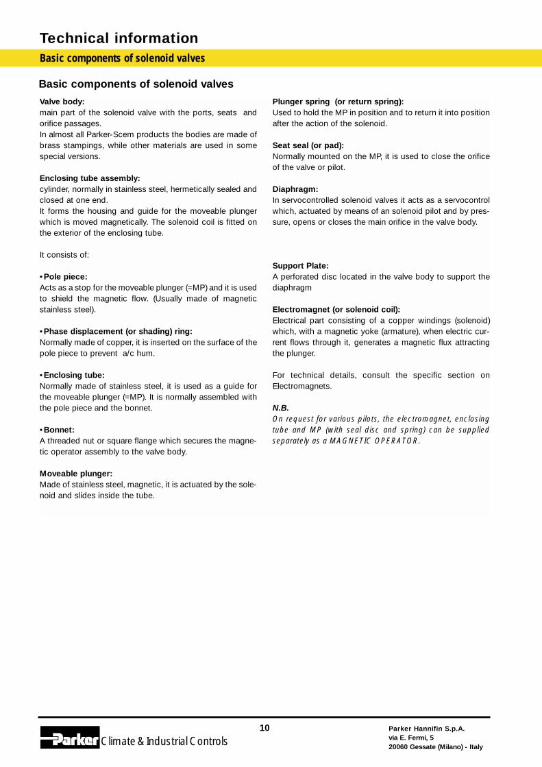
Basic components of solenoid valves
Valve body:main part of the solenoid valve with the ports, seats andorifice passages.In almost all Parker-Scem products the bodies are made ofbrass stampings, while other materials are used in somespecial versions.
Enclosing tube assembly:cylinder, normally in stainless steel, hermetically sealed andclosed at one end.It forms the housing and guide for the moveable plungerwhich is moved magnetically. The solenoid coil is fitted onthe exterior of the enclosing tube.
It consists of:
•Pole piece:Acts as a stop for the moveable plunger (=MP) and it is usedto shield the magnetic flow. (Usually made of magneticstainless steel).
•Phase displacement (or shading) ring:Normally made of copper, it is inserted on the surface of thepole piece to prevent a/c hum.
•Enclosing tube:Normally made of stainless steel, it is used as a guide forthe moveable plunger (=MP). It is normally assembled withthe pole piece and the bonnet.
•Bonnet:A threaded nut or square flange which secures the magne-tic operator assembly to the valve body.
Moveable plunger:Made of stainless steel, magnetic, it is actuated by the sole-noid and slides inside the tube.
Plunger spring (or return spring):Used to hold the MP in position and to return it into positionafter the action of the solenoid.
Seat seal (or pad):Normally mounted on the MP, it is used to close the orificeof the valve or pilot.
Diaphragm:In servocontrolled solenoid valves it acts as a servocontrolwhich, actuated by means of an solenoid pilot and by pres-sure, opens or closes the main orifice in the valve body.
Support Plate:A perforated disc located in the valve body to support thediaphragm
Electromagnet (or solenoid coil):Electrical part consisting of a copper windings (solenoid)which, with a magnetic yoke (armature), when electric cur-rent flows through it, generates a magnetic flux attractingthe plunger.
For technical details, consult the specific section onElectromagnets.
N.B.On request for various pilots, the electromagnet, enclosingtube and MP (with seal disc and spring) can be suppliedseparately as a MAGNETIC OPERATOR.
Technical terminology used in the catalogue
Parker Hannifin S.p.A.via E. Fermi, 520060 Gessate (Milano) - Italy
11
Climate& Industrial Controls
Technical information
Technical terminology for using the tablesThe basic technical features
of each solenoid valve model are indicated in the tables with the following headings:
Fittings (ports):according to the application of the solenoid valves fit-tings may be:- threaded in inches (G);- male SAE threaded with card;- solder;- special where indicated (see solenoid valve drawing).
Passage (ND):main orifice diameter(orifice)(nominal diameter)
Flow coefficient:the quantity of water, from +5°C to +30°C, which flowsthrough the solenoid valve with a pressure drop of 1bar (100 KPa-0.1 MPa) expressed in m3/h (cubicmetres per hour).
Minimum operating pressure:the lowest differential pressure required for operation,expressed in bar.In “direct operated”solenoid valves a minimum pressure drop is notrequired.In “servocontrolled”solenoid valves the minimum differential pressure indi-cated in the table is required.
Maximum operating pressure differential (M.O.P.D.):the highest working differential pressure with 90% ofthe rated voltage (-10% Vn) applied to the solenoidcoil (for a.c.) and with 95% of the rated voltage (-5%Vn) (for d.c.).
NP - Maximum test pressure:the maximum static pressure which can be applied tothe solenoid valve to check the tightness of themechanical seals (threads, welds) and the mechanicalresistance of the materials.We recommend applying this pressure
simultaneously to all fittings to avoid damage to the internal parts, in particular theseals.
Safe working pressure (S.W.P.):the line or system pressure to which the valve can besubjected safely.
Valve type: see example of solenoid valve nomenclature.
Coil type:see coil coding example.
Power:the rated power under normal conditions of the sole-noid expressed in W.
Materials:Body - main material of the valve body:
BR = brassSeals - materials used for seal disc, diaphragms,
gaskets.
The following abbreviations are used:
N = NBR (nitrile butadene rubber)•Synthetic elastomer of standard quality for neutralfluids, such as air, water and oils with working tempe-ratures from -10°C to +90°C.
F = CR (chloroprene)•Synthetic elastomer particularly suitable for water,mineral oils, refrigerants, with working temperaturesfrom -30°C to +90°C.
H = EPDM (ethylene propylene)•Synthetic elastomer suitable for hot water and steamwith working temperatures from -10°C to +140°C.
V = FPM (Viton)•Fluorinated elastomer suitable for oils, fuel gases,petrols and solvents. Working temperatures from-10°C to +140°C.
R = Ruby•Synthetic corundum (hard stone) with high hardnessvalues and total inertia for all types of fluids.Working temperatures from -40°C to +180°C.
T = PTFE (Teflon)•Plastic material without springback and inert to mostfluids, including refrigerants.Working temperatures from -40°C to +180°C.In the case of “Teflon diaphragm ”, this refers to aglass fiber fabric between two layers of PTFE.
L = PTFE with filler (Rulon)•Plastic material with coloured mineral fillers, withoutspringback, inert to most fluids, including refrigerants.Working temperature from -40°C to +180°C.More resistant than virgin PTFE to compression and wear.
Weight:weight of the complete valve without accessories (kg).
For further explanation on how to use the tables see pp 2-3.
Technical informationConstruction materials
Parker Hannifin S.p.A.via E. Fermi, 520060 Gessate (Milano) - Italy
12
Climate& Industrial Controls
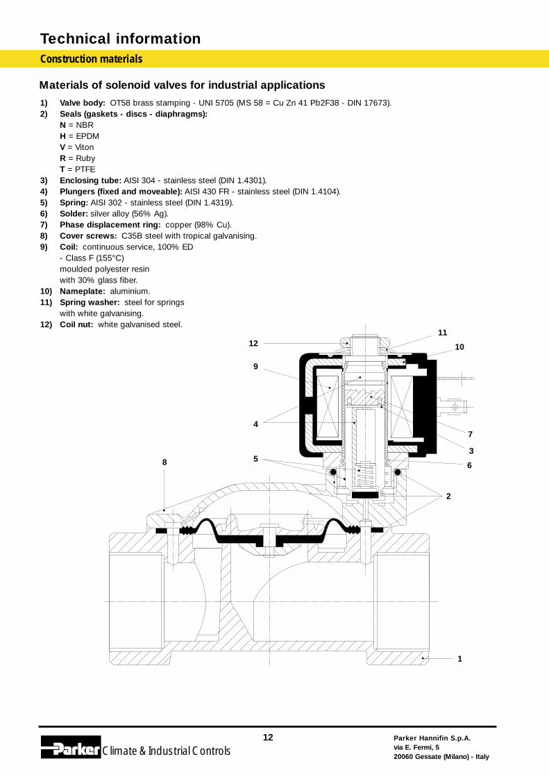
Materials of solenoid valves for industrial applications
1) Valve body: OT58 brass stamping - UNI 5705 (MS 58 = Cu Zn 41 Pb2F38 - DIN 17673).2) Seals (gaskets - discs - diaphragms):
N = NBRH = EPDMV = VitonR = RubyT = PTFE
3) Enclosing tube: AISI 304 - stainless steel (DIN 1.4301).4) Plungers (fixed and moveable): AISI 430 FR - stainless steel (DIN 1.4104).5) Spring: AISI 302 - stainless steel (DIN 1.4319).6) Solder: silver alloy (56% Ag).7) Phase displacement ring: copper (98% Cu).8) Cover screws: C35B steel with tropical galvanising.9) Coil: continuous service, 100% ED
- Class F (155°C)moulded polyester resinwith 30% glass fiber.
10) Nameplate: aluminium.11) Spring washer: steel for springs
with white galvanising.12) Coil nut: white galvanised steel.
1
2
3
10
1112
4
6
7
9
85
11
10
7
3
6
2
1
8
12
9
4
5
Conversion tables
Parker Hannifin S.p.A.via E. Fermi, 520060 Gessate (Milano) - Italy
13
Climate& Industrial Controls
Technical information
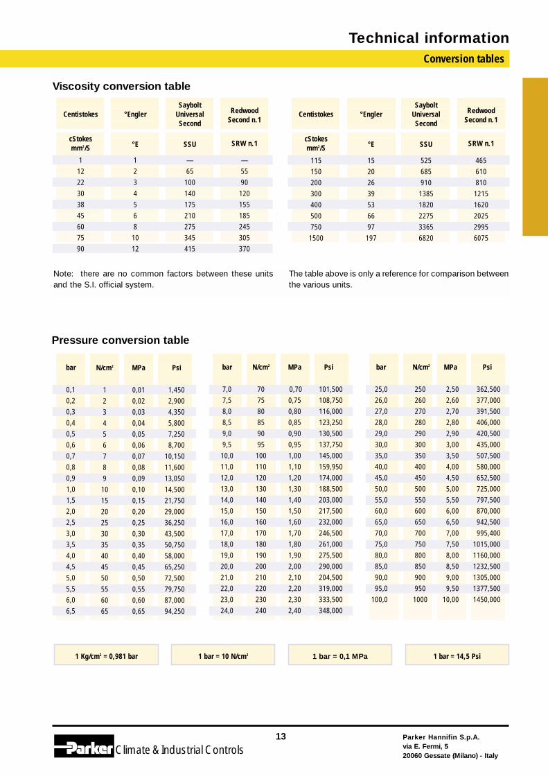
Viscosity conversion table
Pressure conversion table
Note: there are no common factors between these unitsand the S.I. official system.
The table above is only a reference for comparison betweenthe various units.
bar
7,07,58,08,59,09,510,011,012,013,014,015,016,017,018,019,020,021,022,023,024,0
N/cm2
707580859095100110120130140150160170180190200210220230240
MPa
0,700,750,800,850,900,951,001,101,201,301,401,501,601,701,801,902,002,102,202,302,40
Psi
101,500108,750116,000123,250130,500137,750145,000159,950174,000188,500203,000217,500232,000246,500261,000275,500290,000204,500319,000333,500348,000
bar
25,026,027,028,029,030,035,040,045,050,055,060,065,070,075,080,085,090,095,0
100,0
N/cm2
2502602702802903003504004505005506006507007508008509009501000
MPa
2,502,602,702,802,903,003,504,004,505,005,506,006,507,007,508,008,509,009,50
10,00
Psi
362,500377,000391,500406,000420,500435,000507,500580,000652,500725,000797,500870,000942,500995,400
1015,0001160,0001232,5001305,0001377,5001450,000
Centistokes °EnglerSaybolt
UniversalSecond
RedwoodSecond n.1
Centistokes °EnglerSaybolt
UniversalSecond
RedwoodSecond n.1
cStokesmm2/S °E SSU SRW n.1
cStokesmm2/S °E SSU SRW n.1
11222303845607590
12345681012
—65100140175210275345415
—5590120155185245305370
1151502003004005007501500
15202639536697197
52568591013851820227533656820
46561081012151620202529956075
bar
0,10,20,30,40,50,60,70,80,91,01,52,02,53,03,54,04,55,05,56,06,5
N/cm2
123456789101520253035404550556065
MPa
0,010,020,030,040,050,060,070,080,090,100,150,200,250,300,350,400,450,500,550,600,65
Psi
1,4502,9004,3505,8007,2508,700
10,15011,60013,05014,50021,75029,00036,25043,50050,75058,00065,25072,50079,75087,00094,250
1 Kg/cm2 = 0,981 bar 1 bar = 10 N/cm2 1 bar = 0,1 MPa 1 bar = 14,5 Psi
°C
105110115120125130135140145150155160165170175180185190195200205210215220225230235240245250255260265270275280285290295300310320330340350360370380390400
°C
51525354555657585960616263646566676869707172737475767778798081828384858687888990919293949596979899100
°C
1234567891011121314151617181920212223242526272829303132333435363738394041424344454647484950
°F
-58,0-56,2-54,4-52,6-50,8-49,0-47,2-45,4-43,6-41,8-40,0-38,2-36,4-34,6-32,8-31,0-29,2-27,4-25,6-23,8-22,0-20,2-18,4-16,6-14,8-13,0-11,2- 9,4- 7,6- 5,8- 4,0- 2,2- 0,4
1,43,25,06,88,6
10,412,214,015,817,619,421,223,024,826,628,430,232,0
Technical information
Parker Hannifin S.p.A.via E. Fermi, 520060 Gessate (Milano) - Italy
14
Climate& Industrial Controls
°C
-50-49-48-47-46-45-44-43-42-41-40-39-38-37-36-35-34-33-32-31-30-29-28-27-26-25-24-23-22-21-20-19-18-17-16-15-14-13-12-11-10- 9- 8- 7 - 6- 5- 4- 3- 2- 1
0
K
223224225226227228229230231232233234235236237238239240241242243244245246247248249250251252253254255256257258259260261262263264265266267268269270271272273
K
274275276277278279280281282283284285286287288289290291292293294295296297298299300301302303304305306307308309310311312313314315316317318319320321322323
°F
33,835,637,439,241,042,844,646,448,250,051,853,655,457,259,060,862,664,466,268,069,871,673,475,277,078,280,682,484,286,087,889,691,493,295,096,898,6
100,4102,2104,0105,8107,6109,4111,2113,0114,8116,6118,4120,2122,0
K
324325326327328329330331332333334335336337338339340341342343344345346347348349350351352353354355356357358359360361362363364365366367368369370371372373
°F
123,8125,6127,4129,2131,0132,8134,6136,4138,2140,0141,8143,6145,4147,2149,0150,8152,6154,4156,2158,0159,8161,6163,4165,2167,0168,8170,6172,4174,2176,0177,8179,6181,4183,2185,0186,8188,6190,4192,2194,0195,8197,6199,4201,2203,0204,8206,6208,4210,2212,0
K
378383388393398403408413418423428433438443448453458463468473478483488493498503508513518523528533538543548553558563568573583593603613523633643653663673
°F
221,0230,0239,0248,0257,0266,0275,0284,0293,0302,0311,0320,0329,0338,0347,0356,0365,0374,0383,0392,0401,0410,0419,0428,0437,0446,0455,0464,0473,0482,0491,0500,0509,0518,0527,0536,0545,0554,0563,0572,0590,0608,0626,0644,0662,0680,0698,0716,0734,0752,0
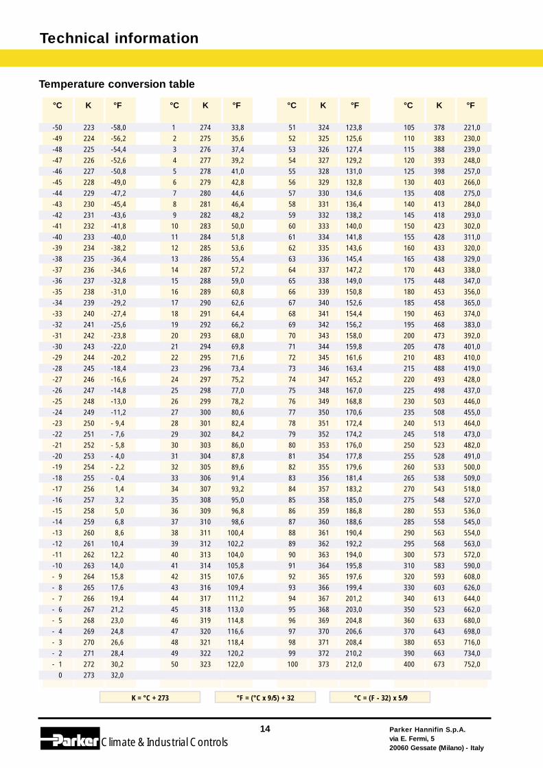
Temperature conversion table
K = °C + 273 °F = (°C x 9/5) + 32 °C = (F - 32) x 5/9
Parker Hannifin S.p.A.via E. Fermi, 520060 Gessate (Milano) - Italy
15
Climate& Industrial Controls
Technical information
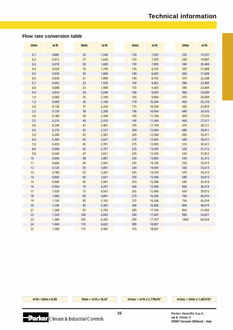
Flow rate conversion table
I/min
0,10,20,30,40,50,60,70,80,91,01,52,02,53,03,54,04,55,06,07,08,09,0
10111213141516171819202122232425
m3/h
0,0060,0120,0180,0240,0300,0360,0420,0480,0540,0600,0900,1200,1500,1800,2100,2400,2700,3000,3600,4200,4800,5400,6000,6600,7200,7800,8400,9000,9601,0201,0801,1401,2001,2601,3201,3801,4401,500
I/min
26272829303132333435363738394041424344454647484950556065707580859095
100105110115
m3/h
1,5601,6201,6801,7401,8001,8601,9201,9802,0402,1002,1602,2202,2802,3402,4102,4612,5212,5812,6412,7012,7612,8212,8812,9413,0013,3013,6013,9014,2014,5014,8015,1025,4025,7026,0026,3026,6026,902
I/min
120125130135140145150155160165170175180185190195200205210215220225230235240245250255260265270275280285290295300310
m3/h
7,2027,5037,8038,1038,4038,7039,0029,3039,6039,904
10,20410,50410,80411,10411,40411,70412,00412,30412,60512,90513,20513,50513,80514,10514,40514,70515,00615,30615,60615,90616,20616,50616,80617,10617,40717,70718,00718,607
I/min
3203303403503603703803904004104204304404504604704804905005105205305405505605705805906006507007508008509001000
m3/h
19,20719,80720,40821,00821,60822,20822,80923,40924,00924,60925,21025,81026,41027,01027,61128,21128,81129,41130,01230,61231,21231,81232,41333,01333,61334,21334,81335,41436,01439,01540,01645,01848,01951,02054,02160,024
m3/h = I/min x 0,06 I/min = m3/h x 16,67 m3/sec = m3/h x 2,778x10-4 m3/sec = I/min x 1,667x10-5
Technical information
Parker Hannifin S.p.A.via E. Fermi, 520060 Gessate (Milano) - Italy
16
Climate& Industrial Controls
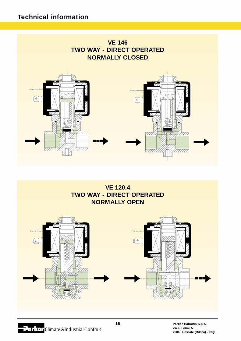
VE 146TWO WAY - DIRECT OPERATED
NORMALLY CLOSED
VE 120.4TWO WAY - DIRECT OPERATED
NORMALLY OPEN
Parker Hannifin S.p.A.via E. Fermi, 520060 Gessate (Milano) - Italy
17
Climate& Industrial Controls
Technical information
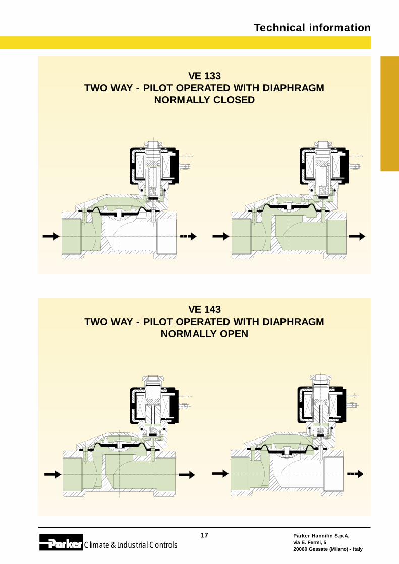
VE 133TWO WAY - PILOT OPERATED WITH DIAPHRAGM
NORMALLY CLOSED
VE 143TWO WAY - PILOT OPERATED WITH DIAPHRAGM
NORMALLY OPEN
Technical information
Parker Hannifin S.p.A.via E. Fermi, 520060 Gessate (Milano) - Italy
18
Climate& Industrial Controls
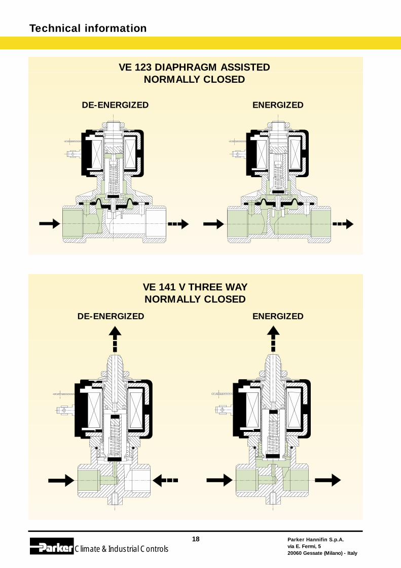
VE 123 DIAPHRAGM ASSISTEDNORMALLY CLOSED
VE 141 V THREE WAYNORMALLY CLOSED
DE-ENERGIZED ENERGIZED
DE-ENERGIZED ENERGIZED
Parker Hannifin S.p.A.via E. Fermi, 520060 Gessate (Milano) - Italy
19
Climate& Industrial Controls
Technical information
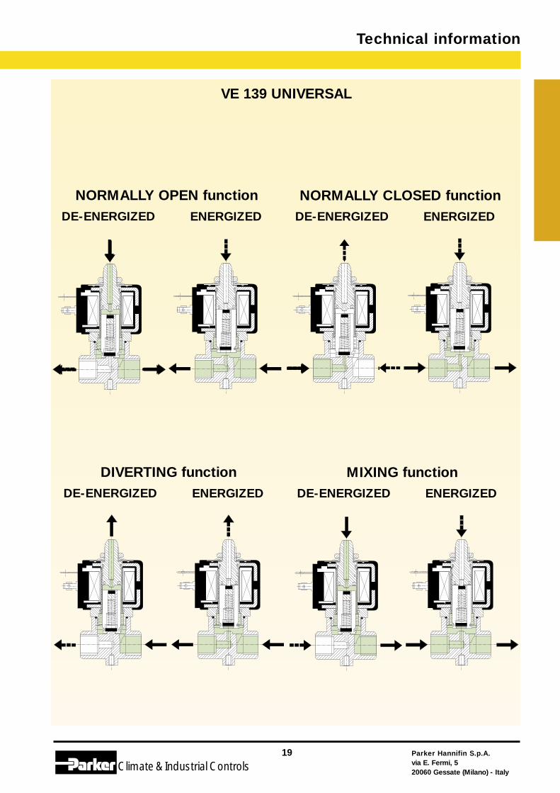
VE 139 UNIVERSAL
ENERGIZEDDE-ENERGIZEDENERGIZEDDE-ENERGIZED
MIXING functionDIVERTING function
ENERGIZEDDE-ENERGIZEDENERGIZEDDE-ENERGIZED
NORMALLY CLOSED functionNORMALLY OPEN function
Ps
Ø D
Rs
Sp
P1 P2
MpFG
Vs
Nr
Cr
20 - D
1 - D 10 - D
15 - D
VE1
Technical information
Parker Hannifin S.p.A.via E. Fermi, 520060 Gessate (Milano) - Italy
20
Climate& Industrial Controls
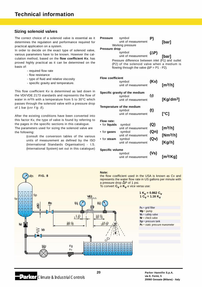
The correct choice of a solenoid valve is essential as itdetermines the regulation and performance required forpractical application on a system.In order to decide on the exact type of solenoid valve,various parameters have to be known. However the cal-culation method, based on the flow coefficient Kv, hasproved highly practical as it can be determined on thebasis of:
- required flow rate- flow resistance- type of fluid and relative viscosity- specific gravity and temperature.
This flow coefficient Kv is determined as laid down inthe VDI/VDE 2173 standards and represents the flow ofwater in m3/h with a temperature from 5 to 30°C whichpasses through the solenoid valve with a pressure dropof 1 bar (see Fig. 8).
After the existing conditions have been converted intothis factor Kv, the type of valve is found by referring tothe pages in the specific sections in this catalogue.The parameters used for sizing the solenoid valve arethe following:
(consult the conversion tables of the variousunits of measurement as defined by the ISO(International Standards Organisation) - I.S.(International System) set out in this catalogue)
P)Meßeinheit [bar]
BetriebsdruckDruckverlust
Symbol (∆P)Meßeinheit [bar]
Differenz zwischen dem Druck am Eingang (P1)und am Ausgang (P2) des Magnetventils ( ∆P = P1- P2 ). bei Durchgang eines Betriebsstoffes.
DurchsatzfaktorSymbol (Kv)Meßeinheit [m3/h]
Spezifisches Gewicht des Betriebsstoffes Symbol (γ)Meßeinheit [Kg/dm3]
Temperatur des BetriebsstoffesSymbol (t)Meßeinheit [°C]
Durchsatz• für Flüssigstoffe Symbol (Q)
Meßeinheit [m3/h]• für Gase Symbol (Qn)
Meßeinheit [Nm3/h] • für Dampf Symbol (Qv)
Meßeinheit [Kg/h]
Spezifisches VolumenSymbol (Vs)Meßeinheit [m3/Kg]
1 Kv = 0.862 Cv1 Cv = 1.16 Kv
Sizing solenoid valves
FIG. 8
FG = grid filterMp = pumpVs = safety valveNr = check valveSp = pressure tankPs = static pressure manometer
Pressure symbolunit of measurement
Working pressurePressure drop
symbolunit of measurement
Flow coefficientsymbolunit of measurement
Specific gravity of the mediumsymbolunit of measurement
Temperature of the mediumsymbolunit of measurement
Specific volumesymbolunit of measurement
Flow rate:• for liquids symbol
unit of measurement • for gases symbol
unit of measurement• for steam symbol
unit of measurement
Pressure difference between inlet (P1) and outlet(P2) of the solenoid valve when a medium isflowing through the valve (∆P = P1 - P2).
Note:the flow coefficient used in the USA is known as Cv andrepresents the water flow rate in US gallons per minute witha pressure drop ∆P of 1 psi. To convert Cv e Kv e vice versa use:
Sp
Ps
Rs
Nr
Vs
Mp Fg
Cr
20 D 15 D
10 D1 D
ØD P1 P2
VE1
Parker Hannifin S.p.A.via E. Fermi, 520060 Gessate (Milano) - Italy
21
Climate& Industrial Controls
Technical information
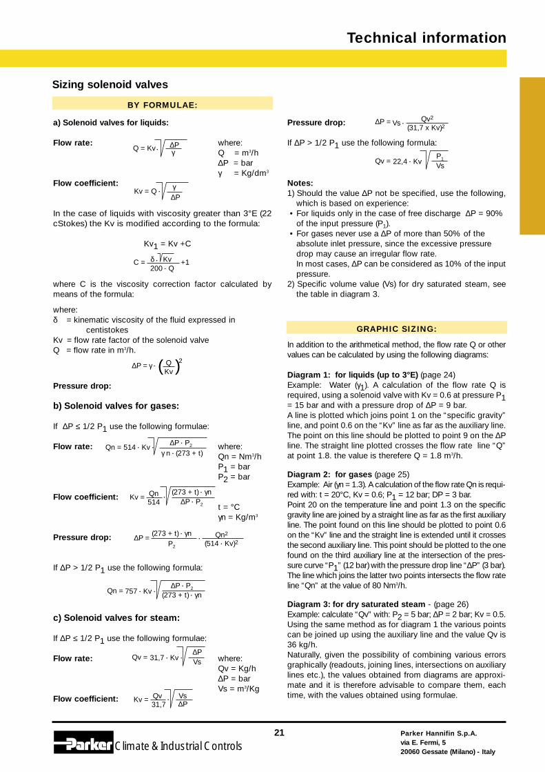
BY FORMULAE:
a) Solenoid valves for liquids:
Flow rate: where:Q = m3/h∆P = barγ = Kg/dm3
Flow coefficient:
In the case of liquids with viscosity greater than 3°E (22cStokes) the Kv is modified according to the formula:
Kv1 = Kv +C
where C is the viscosity correction factor calculated bymeans of the formula:
where:δ = kinematic viscosity of the fluid expressed in
centistokesKv = flow rate factor of the solenoid valveQ = flow rate in m3/h.
Pressure drop:
b) Solenoid valves for gases:
If ∆P ≤ 1/2 P1 use the following formulae:
Flow rate: where: Qn = Nm3/h P1 = bar P2 = bar
Flow coefficient:t = °Cγn = Kg/m3
Pressure drop:
If ∆P > 1/2 P1 use the following formula:
c) Solenoid valves for steam:
If ∆P ≤ 1/2 P1 use the following formulae:
Flow rate: where:Qv = Kg/h∆P = barVs = m3/Kg
Flow coefficient:
Pressure drop:
If ∆P > 1/2 P1 use the following formula:
Notes:1) Should the value ∆P not be specified, use the following,
which is based on experience:• For liquids only in the case of free discharge ∆P = 90%
of the input pressure (P1).• For gases never use a ∆P of more than 50% of the
absolute inlet pressure, since the excessive pressuredrop may cause an irregular flow rate.In most cases, ∆P can be considered as 10% of the inputpressure.
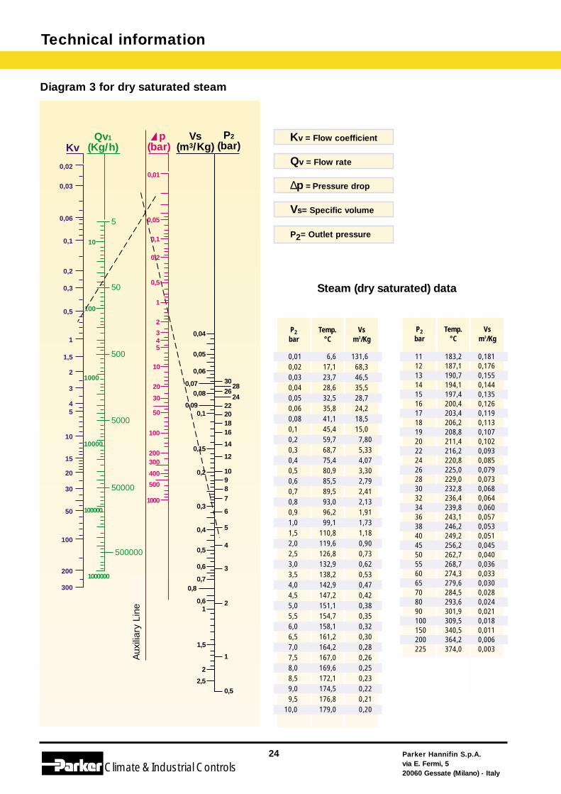
2) Specific volume value (Vs) for dry saturated steam, seethe table in diagram 3.
Kv»
GRAPHIC SIZING:
In addition to the arithmetical method, the flow rate Q or othervalues can be calculated by using the following diagrams:
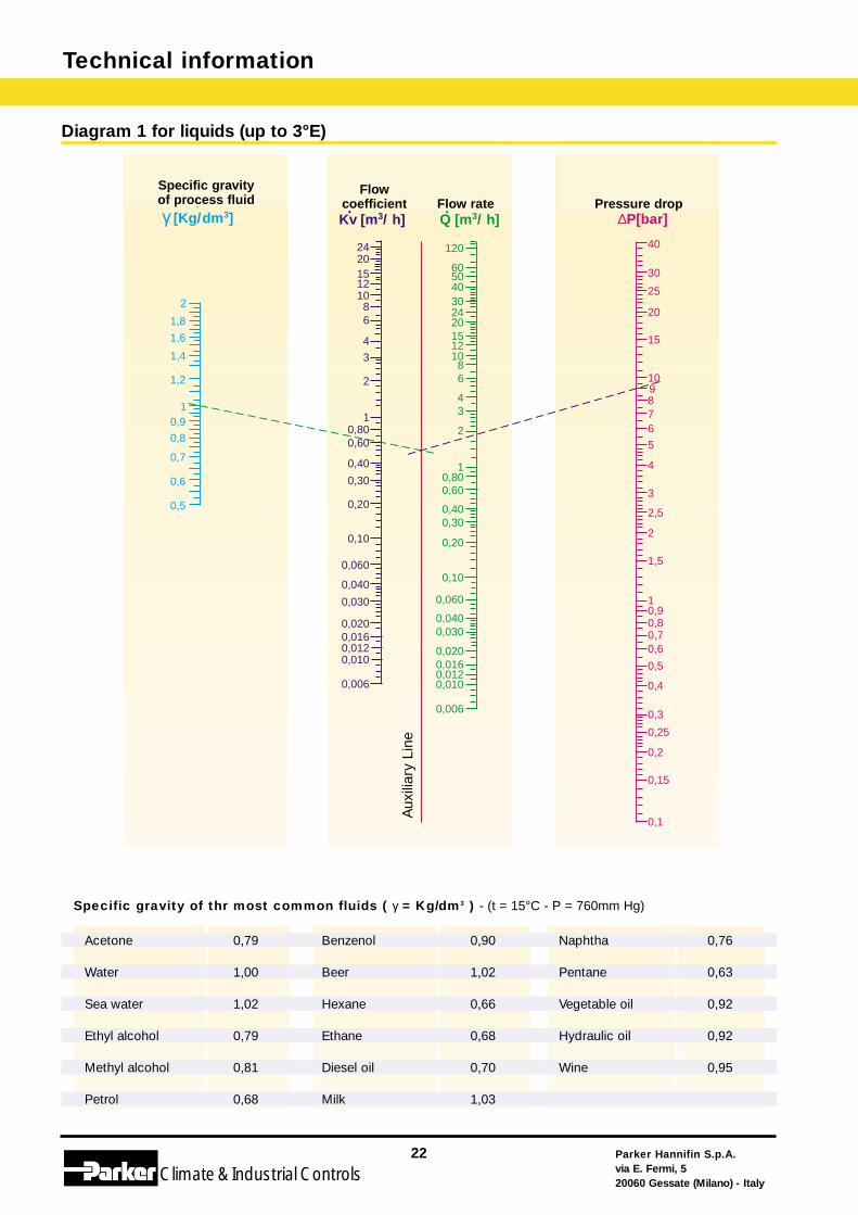
Diagram 1: for liquids (up to 3°E) (page 24)Example: Water (γ1). A calculation of the flow rate Q isrequired, using a solenoid valve with Kv = 0.6 at pressure P1= 15 bar and with a pressure drop of ∆P = 9 bar.A line is plotted which joins point 1 on the “specific gravity”line, and point 0.6 on the “Kv” line as far as the auxiliary line.The point on this line should be plotted to point 9 on the ∆Pline. The straight line plotted crosses the flow rate line “Q”at point 1.8. the value is therefere Q = 1.8 m3/h.
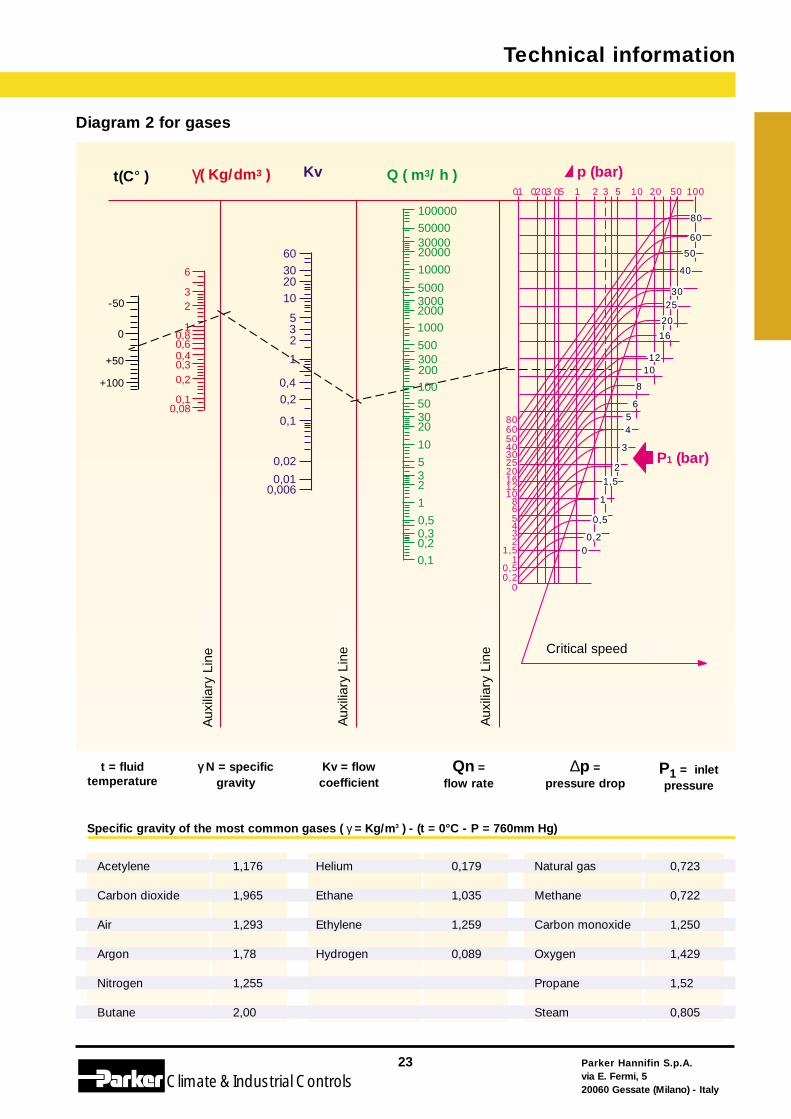
Diagram 2: for gases (page 25)Example: Air (γn = 1.3). A calculation of the flow rate Qn is requi-red with: t = 20°C, Kv = 0.6; P1 = 12 bar; DP = 3 bar.Point 20 on the temperature line and point 1.3 on the specificgravity line are joined by a straight line as far as the first auxiliaryline. The point found on this line should be plotted to point 0.6on the “Kv” line and the straight line is extended until it crossesthe second auxiliary line. This point should be plotted to the onefound on the third auxiliary line at the intersection of the pres-sure curve “P1” (12 bar) with the pressure drop line “∆P” (3 bar).The line which joins the latter two points intersects the flow rateline “Qn” at the value of 80 Nm3/h.
Diagram 3: for dry saturated steam - (page 26)Example: calculate “Qv” with: P2 = 5 bar; ∆P = 2 bar; Kv = 0.5.Using the same method as for diagram 1 the various pointscan be joined up using the auxiliary line and the value Qv is36 kg/h.Naturally, given the possibility of combining various errorsgraphically (readouts, joining lines, intersections on auxiliarylines etc.), the values obtained from diagrams are approxi-mate and it is therefore advisable to compare them, eachtime, with the values obtained using formulae.
Sizing solenoid valves
(273 + t) • γn•
Qn2
(514 • Kv)2P2
∆P =
Qn = 514 • Kv •∆P • P2
(273 + t)γ n •
Kv = •Qv31,7 ∆P
Vs
(31,7 x Kv)2 ∆P = Qv2
Vs •
Kv = (273 + t) • γn
•Qn514 ∆P • P2
Qv = Vs22,4 • KvP1
Qn = (273 + t) • γn757 • Kv •∆P • P2
Q = Kv •∆Pγ
∆PKv = Q •
γ
200 • QC = Kvδ • +1
∆P = γ • ( QKv )
2
Qv = Vs31,7 • Kv •∆P
Technical information
Parker Hannifin S.p.A.via E. Fermi, 520060 Gessate (Milano) - Italy
22
Climate& Industrial Controls
Diagram 1 for liquids (up to 3°E)
Specific gravity of thr most common fluids ( γ = Kg/dm3 ) - (t = 15°C - P = 760mm Hg)
2
1,8
1,6
1,4
1,2
10,9
0,8
0,7
0,6
0,5
242015121086
4
3
2
10,800,60
0,40
0,30
0,20
0,10
0,060
0,040
0,030
0,0200,0160,0120,010
0,006
120
60504030242015121086
43
2
10,800,60
0,400,30
0,20
0,10
0,060
0,0400,030
0,006
0,0200,0160,0120,010
9
40
30
20
25
15
10
876
5
4
3
2,5
2
1,5
10,90,80,70,6
0,5
0,4
0,3
0,25
0,2
0,15
0,1
Line
a au
silia
ria
portataQ [m3/ h]
fattore diportata
Kv [m3/ h]
peso specifico fluido di processo
γ [Kg/dm3]
perdita dicarico∆P[bar]
Acetone 0,79
Water 1,00
Sea water 1,02
Ethyl alcohol 0,79
Methyl alcohol 0,81
Petrol 0,68
Benzenol 0,90
Beer 1,02
Hexane 0,66
Ethane 0,68
Diesel oil 0,70
Milk 1,03
Naphtha 0,76
Pentane 0,63
Vegetable oil 0,92
Hydraulic oil 0,92
Wine 0,95
Aux
iliar
y Li
ne
Specific gravityof process fluid
Flowcoefficient Pressure dropFlow rate
Parker Hannifin S.p.A.via E. Fermi, 520060 Gessate (Milano) - Italy
23
Climate& Industrial Controls
Technical information
Specific gravity of the most common gases ( γ = Kg/m3 ) - (t = 0°C - P = 760mm Hg)
Acetylene 1,176
Carbon dioxide 1,965
Air 1,293
Argon 1,78
Nitrogen 1,255
Butane 2,00
Helium 0,179
Ethane 1,035
Ethylene 1,259
Hydrogen 0,089
Natural gas 0,723
Methane 0,722
Carbon monoxide 1,250
Oxygen 1,429
Propane 1,52
Steam 0,805
t = fluidtemperature
γγ N = specificgravity
Kv = flow coefficient
P1 = inlet pressure
Diagram 2 for gases
γ( Kg/dm3 ) Kv Q ( m3/ h ) p (bar)t(C° )
Line
a au
silia
ria
Line
a au
silia
ria
Line
a au
silia
ria Velocità critica
100000500003000020000
10000
5000300020001000
500300200100503020
10
532
1
0,50,30,20,1
60302010
532
1
0,40,2
0,1
0,02
0,010,006
6
32
10,80,60,40,30,2
0,10,08
-50
0
+50
+100
0,1 0,20,3 0,5 1 2 3 5 10 20 10050
80
60
50
40
3025
20
16
1210
8
654
3
2
80605040302520161210
86
1,5
1
5432
1,5
0,5
0,20
1
0
0,50,2
P1 (bar)
∆p = pressure drop
Qn = flow rate
Critical speed
Aux
iliar
y Li
ne
Aux
iliar
y Li
ne
Aux
iliar
y Li
ne
Technical information
Parker Hannifin S.p.A.via E. Fermi, 520060 Gessate (Milano) - Italy
24
Climate& Industrial Controls
Vs (m3/Kg)
Line
a au
silia
riaP2
(bar)Qv1
(Kg/h)
10
5
100
50
500
1000
10000
5000
50000
100000
500000
1000000
0,01
p (bar)
0,05
0,1
0,2
0,5
1
2
345
10
20
30
50
100
200300
400
500
1000
0,04
0,05
0,06300,07 28260,08 24
0,09 220,1 20
1816
14
120,15
100,2987
6
5
0,3
0,4
4
3
0,5
0,6
0,7
20,61
0,8
1
1,5
2
2,50,5
Kv
0,02
0,03
0,06
0,1
0,2
0,3
0,5
1
1,5
2
3
45
10
15
20
30
50
100
200
300
Diagram 3 for dry saturated steam
Steam (dry saturated) data
P2bar
Temp.°C
Vsm3/Kg
P2bar
Temp.°C
Vsm3/Kg
0,010,020,030,040,050,060,080,10,20,30,40,50,60,70,80,91,01,52,02,53,03,54,04,55,05,56,06,57,07,58,08,59,09,5
10,0
6,617,123,728,632,535,841,145,459,768,775,480,985,589,593,096,299,1
110,8119,6126,8132,9138,2142,9147,2151,1154,7158,1161,2164,2167,0169,6172,1174,5176,8179,0
7,805,334,073,302,792,412,131,911,731,180,900,730,620,530,470,420,380,350,320,300,280,260,250,230,220,210,20
131,6 68,346,535,528,724,218,515,0
11121314151617181920222426283032343638404550556065708090100150200225
183,2187,1190,7194,1197,4200,4203,4206,2208,8211,4216,2220,8225,0229,0232,8236,4239,8243,1246,2249,2256,2262,7268,7274,3279,6284,5293,6301,9309,5340,5364,2374,0
0,1810,1760,1550,1440,1350,1260,1190,1130,1070,1020,0930,0850,0790,0730,0680,0640,0600,0570,0530,0510,0450,0400,0360,0330,0300,0280,0240,0210,0180,0110,0060,003
Kv = Flow coefficient
Qv = Flow rate
∆p = Pressure drop
Vs= Specific volume
P2= Outlet pressure
Aux
iliar
y Li
ne
Parker Hannifin S.p.A.via E. Fermi, 520060 Gessate (Milano) - Italy
25
Climate& Industrial Controls
Technical information
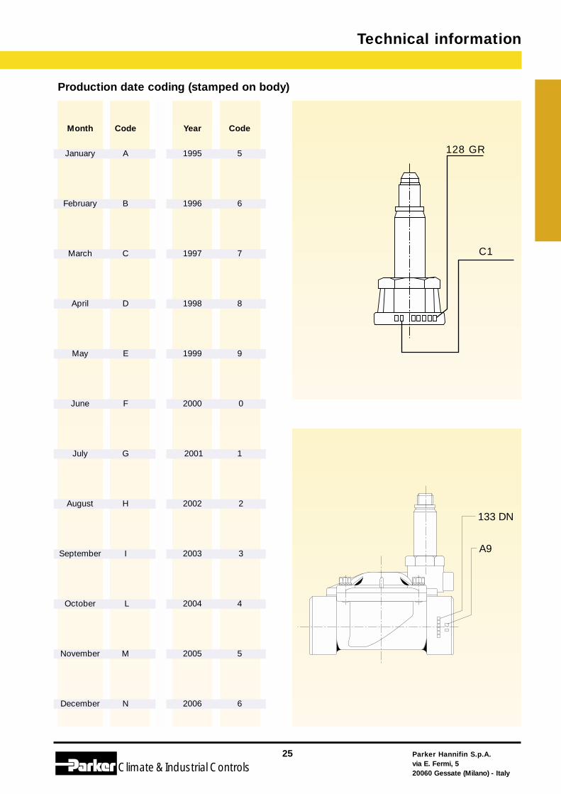
Production date coding (stamped on body)
Month Code Year Code
January A 1995 5
February B 1996 6
March C 1997 7
April D 1998 8
May E 1999 9
June F 2000 0
July G 2001 1
August H 2002 2
September I 2003 3
October L 2004 4
November M 2005 5
December N 2006 6
133 DN
A9
128 GR
C1
Technical information
Parker Hannifin S.p.A.via E. Fermi, 520060 Gessate (Milano) - Italy
26Climate& Industrial Controls
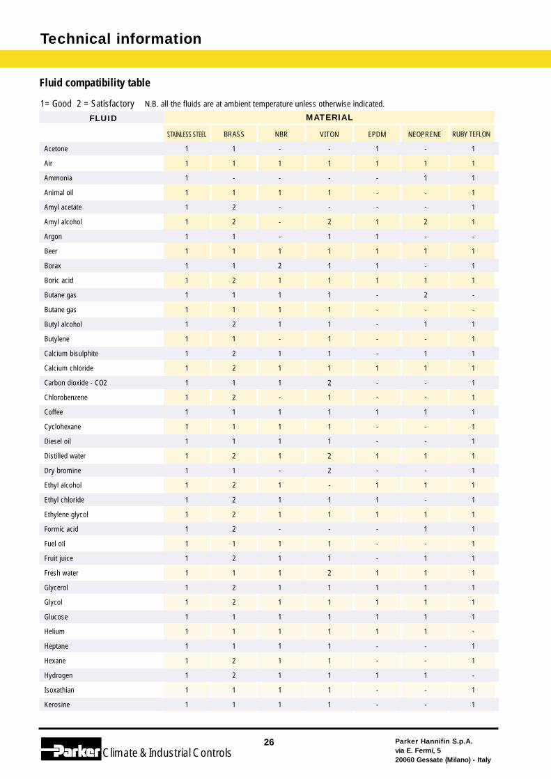
Fluid compatibility table
Acetone 1 1 - - 1 - 1
Air 1 1 1 1 1 1 1
Ammonia 1 - - - - 1 1
Animal oil 1 1 1 1 - - 1
Amyl acetate 1 2 - - - - 1
Amyl alcohol 1 2 - 2 1 2 1
Argon 1 1 - 1 1 - -
Beer 1 1 1 1 1 1 1
Borax 1 1 2 1 1 - 1
Boric acid 1 2 1 1 1 1 1
Butane gas 1 1 1 1 - 2 -
Butane gas 1 1 1 1 - - -
Butyl alcohol 1 2 1 1 - 1 1
Butylene 1 1 - 1 - - 1
Calcium bisulphite 1 2 1 1 - 1 1
Calcium chloride 1 2 1 1 1 1 1
Carbon dioxide - CO2 1 1 1 2 - - 1
Chlorobenzene 1 2 - 1 - - 1
Coffee 1 1 1 1 1 1 1
Cyclohexane 1 1 1 1 - - 1
Diesel oil 1 1 1 1 - - 1
Distilled water 1 2 1 2 1 1 1
Dry bromine 1 1 - 2 - - 1
Ethyl alcohol 1 2 1 - 1 1 1
Ethyl chloride 1 2 1 1 1 - 1
Ethylene glycol 1 2 1 1 1 1 1
Formic acid 1 2 - - - 1 1
Fuel oil 1 1 1 1 - - 1
Fruit juice 1 2 1 1 - 1 1
Fresh water 1 1 1 2 1 1 1
Glycerol 1 2 1 1 1 1 1
Glycol 1 2 1 1 1 1 1
Glucose 1 1 1 1 1 1 1
Helium 1 1 1 1 1 1 -
Heptane 1 1 1 1 - - 1
Hexane 1 2 1 1 - - 1
Hydrogen 1 2 1 1 1 1 -
Isoxathian 1 1 1 1 - - 1
Kerosine 1 1 1 1 - - 1
FLUID MATERIAL
BRASS NBR VITON EPDM NEOPRENE RUBY TEFLONSTAINLESS STEEL
1= Good 2 = Satisfactory N.B. all the fluids are at ambient temperature unless otherwise indicated.
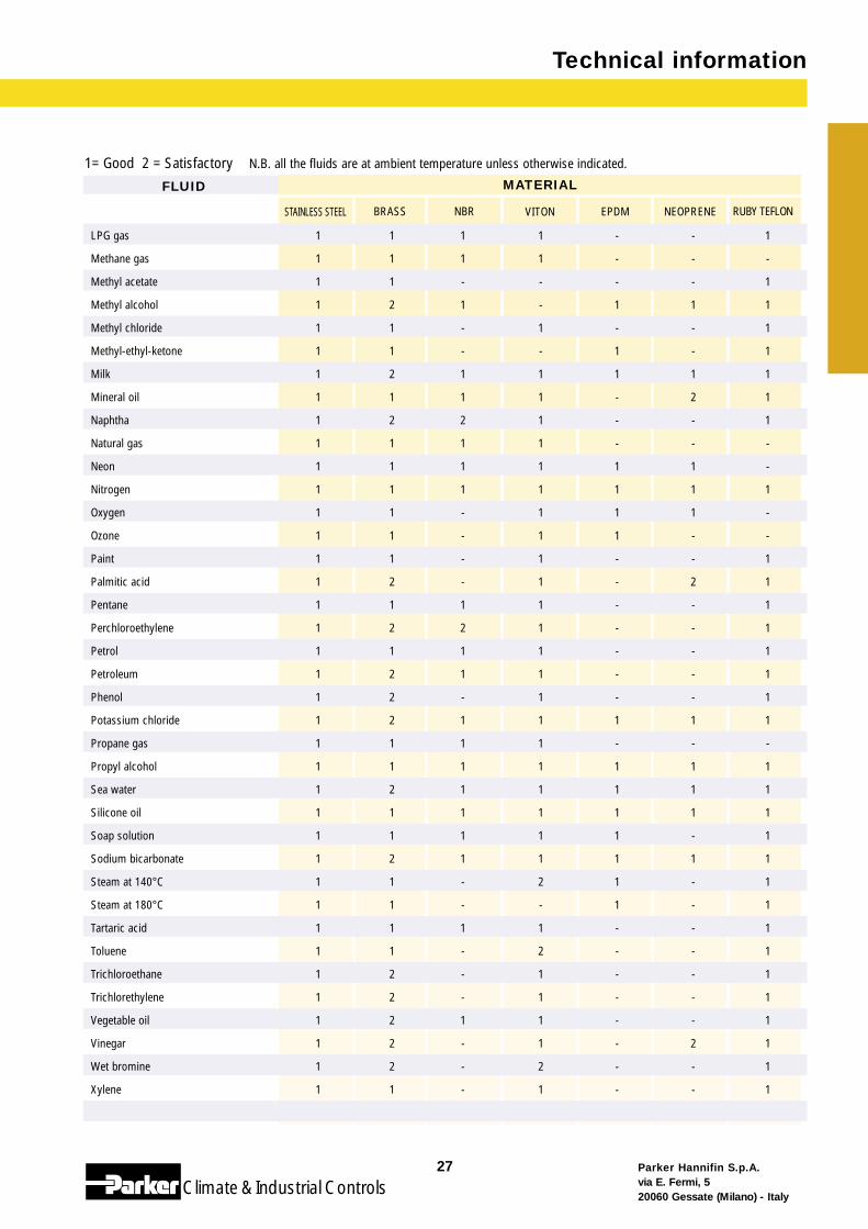
FLUID MATERIAL
BRASS NBR VITON EPDM NEOPRENE RUBY TEFLONSTAINLESS STEEL
1= Good 2 = Satisfactory N.B. all the fluids are at ambient temperature unless otherwise indicated.
Parker Hannifin S.p.A.via E. Fermi, 520060 Gessate (Milano) - Italy
27
Climate& Industrial Controls
Technical information
LPG gas 1 1 1 1 - - 1
Methane gas 1 1 1 1 - - -
Methyl acetate 1 1 - - - - 1
Methyl alcohol 1 2 1 - 1 1 1
Methyl chloride 1 1 - 1 - - 1
Methyl-ethyl-ketone 1 1 - - 1 - 1
Milk 1 2 1 1 1 1 1
Mineral oil 1 1 1 1 - 2 1
Naphtha 1 2 2 1 - - 1
Natural gas 1 1 1 1 - - -
Neon 1 1 1 1 1 1 -
Nitrogen 1 1 1 1 1 1 1
Oxygen 1 1 - 1 1 1 -
Ozone 1 1 - 1 1 - -
Paint 1 1 - 1 - - 1
Palmitic acid 1 2 - 1 - 2 1
Pentane 1 1 1 1 - - 1
Perchloroethylene 1 2 2 1 - - 1
Petrol 1 1 1 1 - - 1
Petroleum 1 2 1 1 - - 1
Phenol 1 2 - 1 - - 1
Potassium chloride 1 2 1 1 1 1 1
Propane gas 1 1 1 1 - - -
Propyl alcohol 1 1 1 1 1 1 1
Sea water 1 2 1 1 1 1 1
Silicone oil 1 1 1 1 1 1 1
Soap solution 1 1 1 1 1 - 1
Sodium bicarbonate 1 2 1 1 1 1 1
Steam at 140°C 1 1 - 2 1 - 1
Steam at 180°C 1 1 - - 1 - 1
Tartaric acid 1 1 1 1 - - 1
Toluene 1 1 - 2 - - 1
Trichloroethane 1 2 - 1 - - 1
Trichlorethylene 1 2 - 1 - - 1
Vegetable oil 1 2 1 1 - - 1
Vinegar 1 2 - 1 - 2 1
Wet bromine 1 2 - 2 - - 1
Xylene 1 1 - 1 - - 1
Technical information
Parker Hannifin S.p.A.via E. Fermi, 520060 Gessate (Milano) - Italy
28
Climate& Industrial Controls
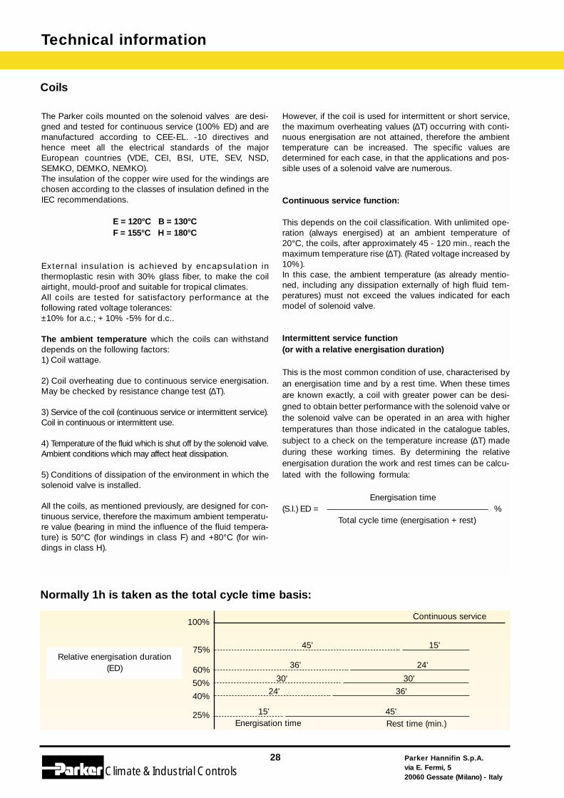
Coils
The Parker coils mounted on the solenoid valves are desi-gned and tested for continuous service (100% ED) and aremanufactured according to CEE-EL. -10 directives andhence meet all the electrical standards of the majorEuropean countries (VDE, CEI, BSI, UTE, SEV, NSD,SEMKO, DEMKO, NEMKO).The insulation of the copper wire used for the windings arechosen according to the classes of insulation defined in theIEC recommendations.
E = 120°C B = 130°CF = 155°C H = 180°C
L’isolamento esterno è ottenuto con l’incapsExternal insulation is achieved by encapsulation inthermoplastic resin with 30% glass fiber, to make the coilairtight, mould-proof and suitable for tropical climates.All coils are tested for satisfactory performance at thefollowing rated voltage tolerances: ±10% for a.c.; + 10% -5% for d.c..
The ambient temperature which the coils can withstanddepends on the following factors:1) Coil wattage.
2) Coil overheating due to continuous service energisation.May be checked by resistance change test (∆T).
3) Service of the coil (continuous service or intermittent service).Coil in continuous or intermittent use.
4) Temperature of the fluid which is shut off by the solenoid valve.Ambient conditions which may affect heat dissipation.
5) Conditions of dissipation of the environment in which thesolenoid valve is installed.
All the coils, as mentioned previously, are designed for con-tinuous service, therefore the maximum ambient temperatu-re value (bearing in mind the influence of the fluid tempera-ture) is 50°C (for windings in class F) and +80°C (for win-dings in class H).
However, if the coil is used for intermittent or short service,the maximum overheating values (∆T) occurring with conti-nuous energisation are not attained, therefore the ambienttemperature can be increased. The specific values aredetermined for each case, in that the applications and pos-sible uses of a solenoid valve are numerous.
Continuous service function:2) Sovratemperatura a saturazione This depends on the coil classification. With unlimited ope-ration (always energised) at an ambient temperature of20°C, the coils, after approximately 45 - 120 min., reach themaximum temperature rise (∆T). (Rated voltage increased by10%).In this case, the ambient temperature (as already mentio-ned, including any dissipation externally of high fluid tem-peratures) must not exceed the values indicated for eachmodel of solenoid valve.
Intermittent service function(or with a relative energisation duration)modello di elettro-valvola.This is the most common condition of use, characterised byan energisation time and by a rest time. When these timesare known exactly, a coil with greater power can be desi-gned to obtain better performance with the solenoid valve orthe solenoid valve can be operated in an area with highertemperatures than those indicated in the catalogue tables,subject to a check on the temperature increase (∆T) madeduring these working times. By determining the relativeenergisation duration the work and rest times can be calcu-lated with the following formula:voro. Con la determinazioiintervalli di lavoro e di riposo con la seguente formula:
Energisation time(S.l.) ED = %
Total cycle time (energisation + rest)
Normally 1h is taken as the total cycle time basis:
Continuous service
Relative energisation duration (ED)
Energisation time Rest time (min.)
100%
75%
60%
50%
40%
25%
45' 15'
36' 24'
30' 30'
24' 36'
15' 45'
Parker Hannifin S.p.A.via E. Fermi, 520060 Gessate (Milano) - Italy
29
Climate& Industrial Controls
Technical information
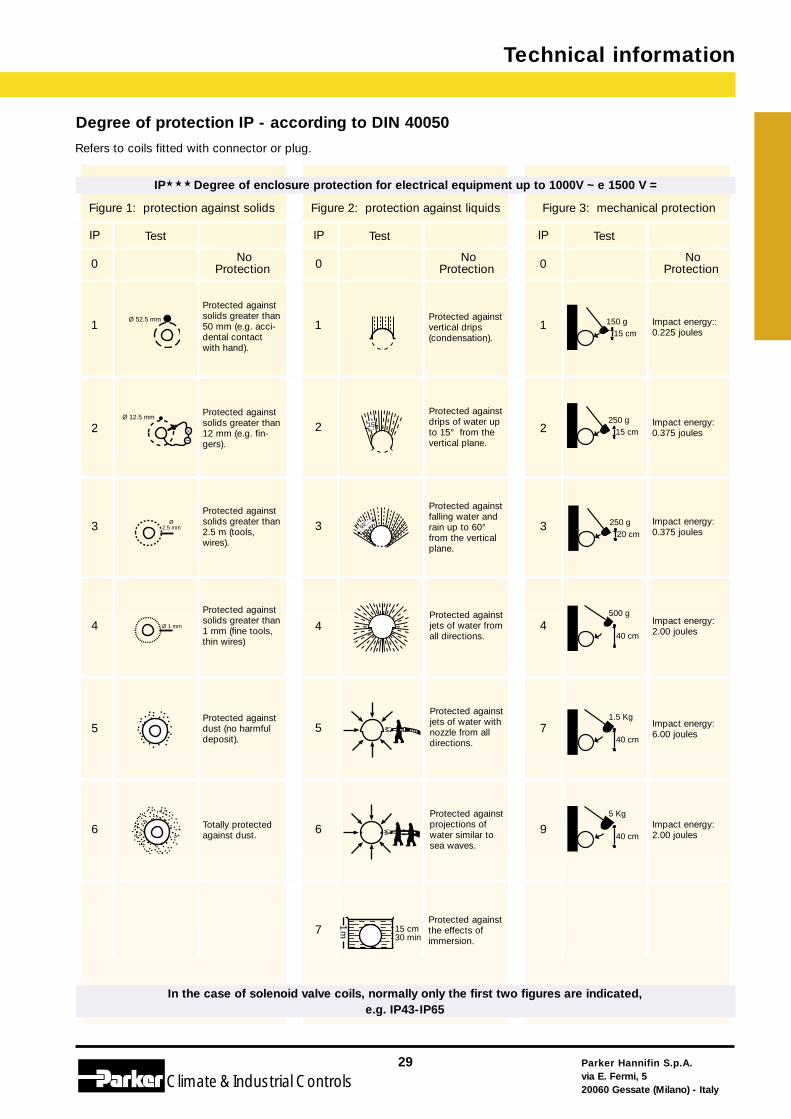
Degree of protection IP - according to DIN 40050
Refers to coils fitted with connector or plug.
Protected againstvertical drips(condensation).
Protected againstdrips of water upto 15° from thevertical plane.
Protected againstfalling water andrain up to 60°from the verticalplane.
Protected againstjets of water fromall directions.
Protected againstjets of water withnozzle from alldirections.
Protected againstprojections ofwater similar tosea waves.
Impact energy::0.225 joules
Impact energy:0.375 joules
Impact energy:0.375 joules
Impact energy:2.00 joules
Impact energy:2.00 joules
Impact energy:6.00 joules
Protected againstthe effects ofimmersion.
1
2
3
4
5
6
1
2
3
4
7
9
1
2
3
4
5
6
7
IP★ ★ ★ Degree of enclosure protection for electrical equipment up to 1000V ~ e 1500 V =
Figure 1: protection against solids Figure 2: protection against liquids Figure 3: mechanical protection
IP Test
0 No Protection
IP Test
0 No Protection
IP Test
0 No Protection
In the case of solenoid valve coils, normally only the first two figures are indicated, e.g. IP43-IP65
Protected againstsolids greater than50 mm (e.g. acci-dental contactwith hand).
Protected againstsolids greater than12 mm (e.g. fin-gers).
Protected againstsolids greater than2.5 m (tools,wires).
Protected againstsolids greater than1 mm (fine tools,thin wires)
Protected againstdust (no harmfuldeposit).
Totally protectedagainst dust.
Ø 52.5 mm 150 g15 cm
Ø 12.5 mm
X
~
15° 250 g15 cm
Ø 2.5 mm 60° 250 g
20 cm
Ø 1 mm
500 g
40 cm
1.5 Kg
40 cm
15 cm30 min
1m
5 Kg
40 cm
Technical information
Parker Hannifin S.p.A.via E. Fermi, 520060 Gessate (Milano) - Italy
30
Climate& Industrial Controls
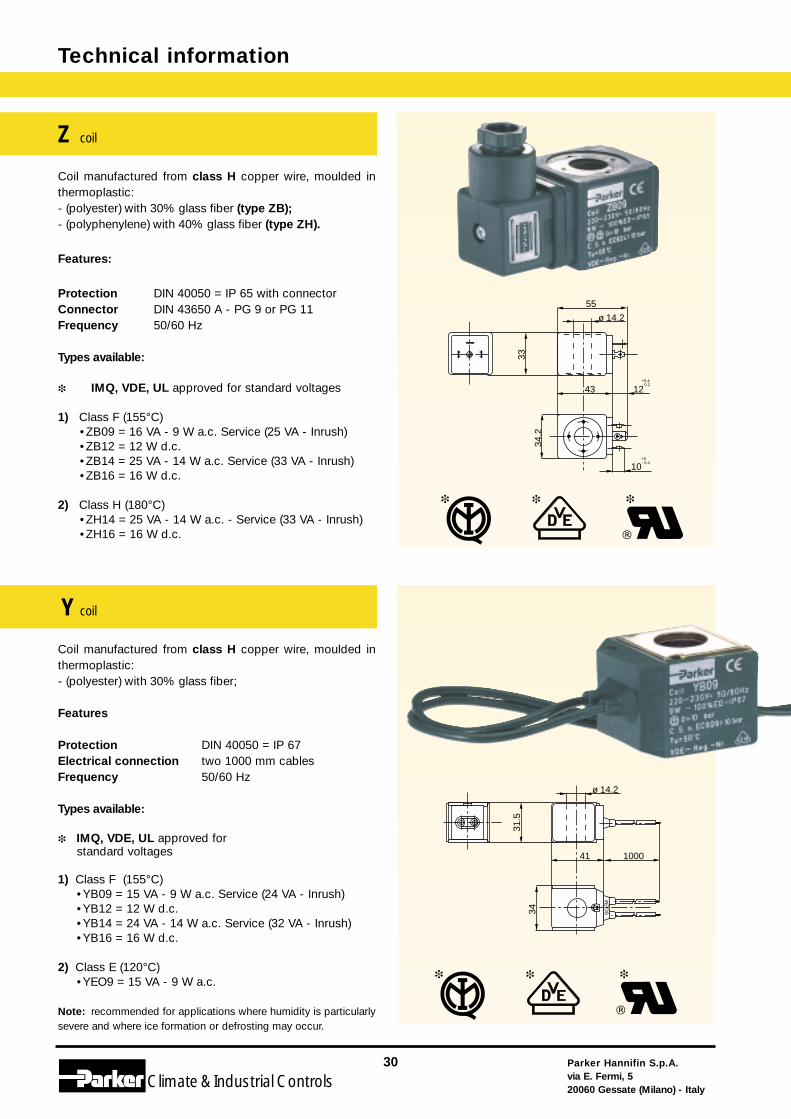
Coil manufactured from class H copper wire, moulded inthermoplastic:- (polyester) with 30% glass fiber (type ZB);- (polyphenylene) with 40% glass fiber (type ZH).
Features:
Protection DIN 40050 = IP 65 with connectorConnector DIN 43650 A - PG 9 or PG 11Frequency 50/60 Hz
Types available:
❉ IMQ, VDE, UL approved for standard voltages
1) Class F (155°C)•ZB09 = 16 VA - 9 W a.c. Service (25 VA - Inrush)•ZB12 = 12 W d.c.•ZB14 = 25 VA - 14 W a.c. Service (33 VA - Inrush)•ZB16 = 16 W d.c.
2) Class H (180°C)•ZH14 = 25 VA - 14 W a.c. - Service (33 VA - Inrush)•ZH16 = 16 W d.c.
Coil manufactured from class H copper wire, moulded inthermoplastic:- (polyester) with 30% glass fiber;
Features
Protection DIN 40050 = IP 67 Electrical connection two 1000 mm cables Frequency 50/60 Hz
Types available:
❉ IMQ, VDE, UL approved for standard voltages
1) Class F (155°C)•YB09 = 15 VA - 9 W a.c. Service (24 VA - Inrush)•YB12 = 12 W d.c.•YB14 = 24 VA - 14 W a.c. Service (32 VA - Inrush)•YB16 = 16 W d.c.
2) Class E (120°C)•YEO9 = 15 VA - 9 W a.c.
Note: recommended for applications where humidity is particularlysevere and where ice formation or defrosting may occur.
Z coil
Y coil
55
ø 14.2
34.2
43+0.4- 0.2
12
+0- 0.4
10
3331
.5
41 1000
ø 14.2
34 SC
EM
Parker Hannifin S.p.A.via E. Fermi, 520060 Gessate (Milano) - Italy
31
Climate& Industrial Controls
Technical information
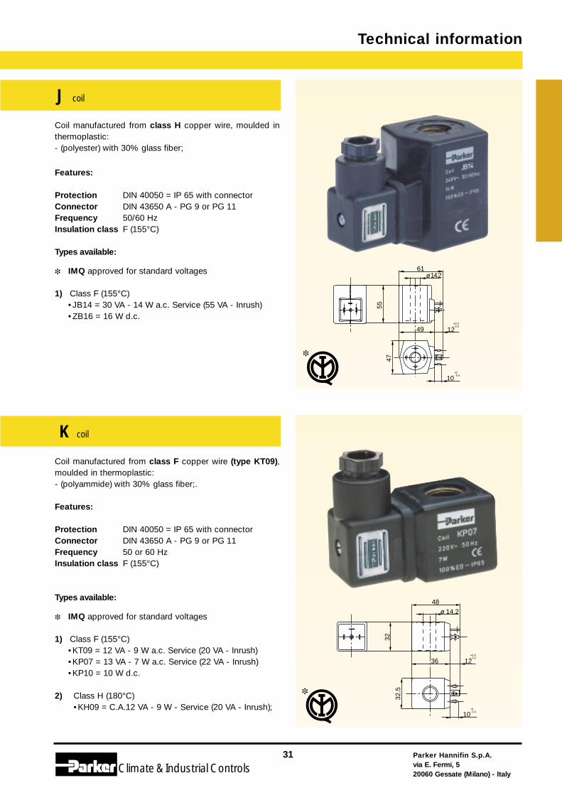
K coil
J coil
Coil manufactured from class H copper wire, moulded inthermoplastic:- (polyester) with 30% glass fiber;
Features:
Protection DIN 40050 = IP 65 with connectorConnector DIN 43650 A - PG 9 or PG 11Frequency 50/60 HzInsulation class F (155°C)
Types available:
❉ IMQ approved for standard voltages
1) Class F (155°C)•JB14 = 30 VA - 14 W a.c. Service (55 VA - Inrush)•ZB16 = 16 W d.c.
Coil manufactured from class F copper wire (type KT09),moulded in thermoplastic:- (polyammide) with 30% glass fiber;.
Features:
Protection DIN 40050 = IP 65 with connectorConnector DIN 43650 A - PG 9 or PG 11Frequency 50 or 60 HzInsulation class F (155°C)
Types available:
❉ IMQ approved for standard voltages
1) Class F (155°C)•KT09 = 12 VA - 9 W a.c. Service (20 VA - Inrush)•KP07 = 13 VA - 7 W a.c. Service (22 VA - Inrush)•KP10 = 10 W d.c.
2) Class H (180°C)•KH09 = C.A.12 VA - 9 W - Service (20 VA - Inrush);
55
ø 14.261
49
47
+0.4- 0.2
12
+0- 0.4
10
48ø 14.2
32.5
36+0.4- 0.2
12
+0- 0.4
10
32
Technical information
Parker Hannifin S.p.A.via E. Fermi, 520060 Gessate (Milano) - Italy
32
Climate& Industrial Controls
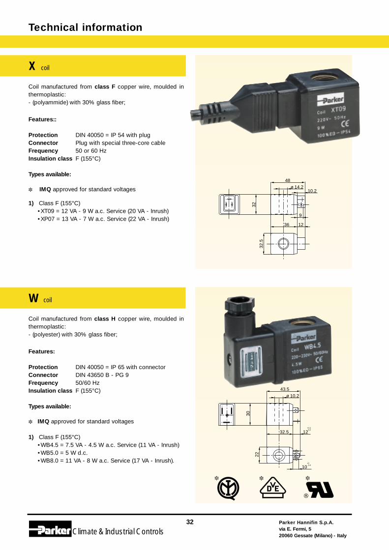
Coil manufactured from class F copper wire, moulded inthermoplastic:- (polyammide) with 30% glass fiber;
Features::
Protection DIN 40050 = IP 54 with plugConnector Plug with special three-core cableFrequency 50 or 60 HzInsulation class F (155°C)
Types available:
❉ IMQ approved for standard voltages
1) Class F (155°C)•XT09 = 12 VA - 9 W a.c. Service (20 VA - Inrush)•XP07 = 13 VA - 7 W a.c. Service (22 VA - Inrush)
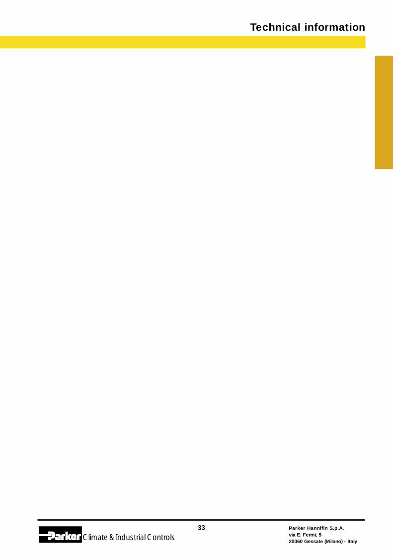
Coil manufactured from class H copper wire, moulded inthermoplastic:- (polyester) with 30% glass fiber;
Features:
Protection DIN 40050 = IP 65 with connectorConnector DIN 43650 B - PG 9 Frequency 50/60 HzInsulation class F (155°C)
Types available:
❉ IMQ approved for standard voltages
1) Class F (155°C)•WB4.5 = 7.5 VA - 4.5 W a.c. Service (11 VA - Inrush)•WB5.0 = 5 W d.c.•WB8.0 = 11 VA - 8 W a.c. Service (17 VA - Inrush).
48ø 14.2
32.5
36 12
32
10.2
9
30
43.5ø 10.2
22
32.5+0.4- 0.2
12
+0- 0.4
10
X coil
W coil
Parker Hannifin S.p.A.via E. Fermi, 520060 Gessate (Milano) - Italy
33
Climate& Industrial Controls
Technical information
Technical information
Parker Hannifin S.p.A.via E. Fermi, 520060 Gessate (Milano) - Italy
34
Climate& Industrial Controls
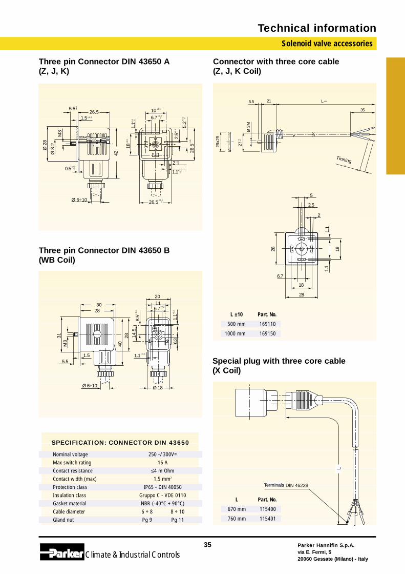
Coil Table
Notes: ● Standard (1) For spare coil order ZB09-ZB12
VALVE SERIES JB14JB16
KP07KT05KT06
KT09KT10
WB4.5WB5.0
XT09 XP07YB09YB12
YB14YB16
YE09ZB09ZB12
ZB14ZB16
ZH14ZH16
KH09
120.4 ● ● ●
123 ● ● ● ● ● ●
126 ● ● ●
128 ● ● ●
131 ● ●
131.4 ●
131.4...G ● ●
133 ● ● ● ●
133...H ● ● ●
133 CMV ● ● ●
135 ●
136 ● ● ●
139 ● ● ●
140 ● ● ● ●
140.2 ● ● ●
141 ● ● ●
143 ● ● ●
146 ● ● ● ● ●
151 ● ● ●
153 ● (1) ● ● ●
156.2 ● ● ●
158 ● ● ●
161.4 ●
168.1 ● ● ●
169.1 ● ● ●
173 ●
174 ●
179 ●
Solenoid valve accessories
Parker Hannifin S.p.A.via E. Fermi, 520060 Gessate (Milano) - Italy
35
Climate& Industrial Controls
Technical information
Three pin Connector DIN 43650 A(Z, J, K)
Ø 6÷10
26.51.5
0.5
Ø 2
8
42± 0.3
+0,7 0
Ø 8
.2
M3
5.5 0-1
26.5
26.5
10
2
1.1
18
2.5
1.1
5.2
6.7
+1.5 0
+0.3 0
+0.2 0
+0,
2
0
+0.2 0
+0.
2
0
+1.
5
±0.1
±0.1
±0.1
35
±10L215.5
Ø 3
M
2729x2
9
+1
-0
stagnato 8
Connector with three core cable(Z, J, K Coil)
Three pin Connector DIN 43650 B(WB Coil)
6.7+0,2
8.5±
0.1
14.5
1.1+ 0.2
6.3
1.1+
0.2
2
31
4028
3028
1.55.5
M3
Ø 6÷10
1120
Ø 18
1
Special plug with three core cable(X Coil)
Terminali DIN 46228
L
SPECIFICATION: CONNECTOR DIN 43650
250 -/ 300V=16 A
≤4 m Ohm1,5 mm2
IP65 - DIN 40050Gruppo C - VDE 0110NBR (-40°C + 90°C)6 ÷ 8 8 ÷ 10Pg 9 Pg 11
Nominal voltageMax switch ratingContact resistanceContact width (max)Protection classInsulation classGasket materialCable diameterGland nut
28
18
18286.7
1.1
1.1
2
2.5
5
L Part. No.
670 mm 115400
760 mm 115401
L ±10 Part. No.
500 mm 169110
1000 mm 169150
Terminals
Tinning
Technical Information
Parker Hannifin S.p.A.via E. Fermi, 520060 Gessate (Milano) - Italy
36
Climate& Industrial ControlsClimate& Industrial Controls
Parker Hannifin S.p.A.via E. Fermi, 520060 Gessate (Milano) - Italy
37
Climate& Industrial Controls
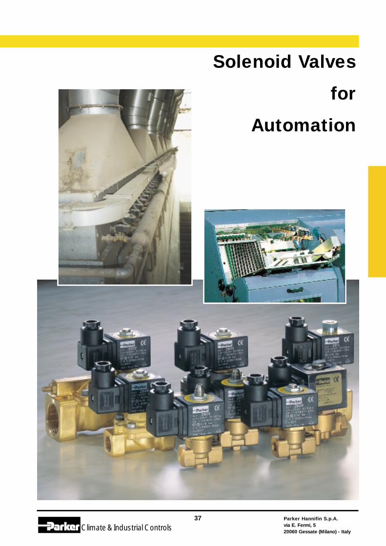
Solenoid Valves
for
Automation
Solenoid Valves for AutomationContents
Parker Hannifin S.p.A.via E. Fermi, 520060 Gessate (Milano) - Italy
38
Climate& Industrial Controls
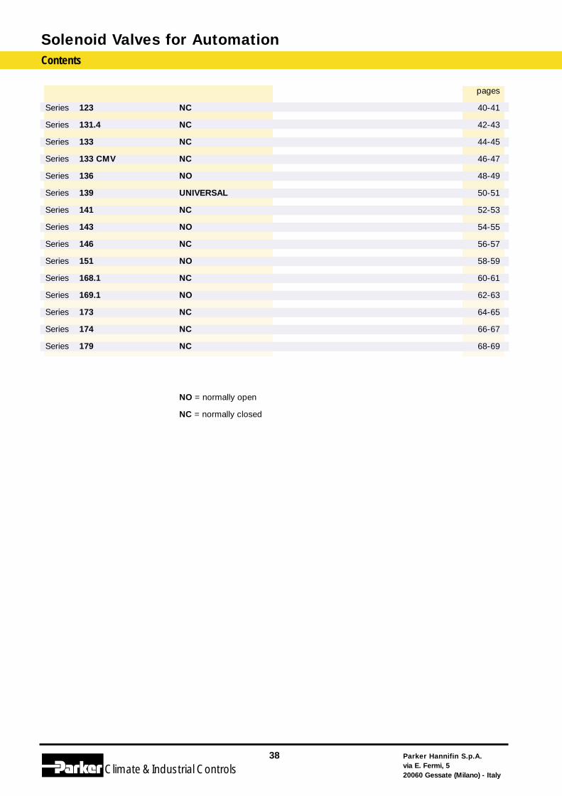
Series 123
Series 131.4
Series 133
Series 133 CMV
Series 136
Series 139
Series 141
Series 143
Series 146
Series 151
Series 168.1
Series 169.1
Series 173
Series 174
Series 179
NC
NC
NC
NC
NO
UNIVERSAL
NC
NO
NC
NO
NC
NO
NC
NC
NC
NO = normally open
NC = normally closed
pages
40-41
42-43
44-45
46-47
48-49
50-51
52-53
54-55
56-57
58-59
60-61
62-63
64-65
66-67
68-69
Index for fittings and M.O.P.D.
Parker Hannifin S.p.A.via E. Fermi, 520060 Gessate (Milano) - Italy
39
Climate& Industrial Controls
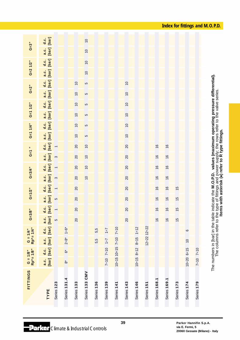
The
num
ber
s in
[bar
] in
the
tab
le in
dic
ate
the
M.O
.P.D
. va
lues
(m
axim
um o
per
atin
g p
ress
ure
diff
eren
tial
).Th
e co
lum
ns r
efer
to
the
typ
e of
fitt
ings
and
pow
er s
upp
ly;
the
row
s re
fer
to t
he v
alve
ser
ies.
Item
s w
ith
aste
risk
(*)
refe
r to
R t
ype
fitti
ngs.
a.c.
[bar
]d.
c.[b
ar]
a.c.
[bar
]d.
c.[b
ar]
a.c.
[bar
]d.
c.[b
ar]
a.c.
[bar
]d.
c.[b
ar]
a.c.
[bar
]d.
c.[b
ar]
a.c.
[bar
]d.
c.[b
ar]
a.c.
[bar
]d.
c.[b
ar]
a.c.
[bar
]d.
c.[b
ar]
a.c.
[bar
]d.
c.[b
ar]
a.c.
[bar
]d.
c.[b
ar]
G=3
/8”
G=1
/2”
G=3
/4”
G=1
”G
=1 1
/4”
G=1
1/2
”G
=2”
G=2
1/2
”F
ITT
ING
S
TY
PE
G =
1/8
”R
p*=
1/8”
G =
1/4
”R
p*=
1/4”
Ser
ies
123
Ser
ies
131.4
Ser
ies
133
Ser
ies
133 C
MV
Ser
ies
136
Ser
ies
139
Ser
ies
141
Ser
ies
143
Ser
ies
146
Ser
ies
151
Ser
ies
168.1
Ser
ies
169.1
Ser
ies
173
Ser
ies
174
Ser
ies
179
5 20 20 16 16 15
1 20 20 16 16 15
5 20 20 16 16 15
1÷6*
5,5
1÷7
7÷10
1÷12
12÷2
2
6
2÷8*
5,5
1÷7
7÷10
8÷15
12÷2
2
10
6*
7÷10
10÷1
5
8÷12
6÷15
7÷10
8*
7÷10
10÷1
5
10÷1
5
10÷2
0
7÷10
1010
a.c.
[bar
]d.
c.[b
ar]
G=3
” 1010
10 5 10
10 5 10
10 5 10
10 5 10
10 5
10
10 5 10
1 20 10 20 16 16
3 20 10 20 16 16
1 20 10 20 16 16
3 20 10 20 16 16
1 20 20 16 16 15
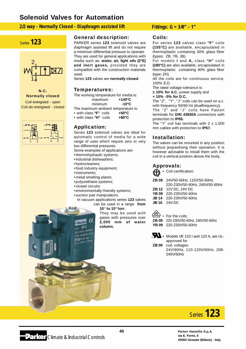
General description:PARKER series 123 solenoid valves arediaphragm assisted lift and do not requirea minimum differential pressure to operate.They are used for general applications withmedia such as: water, air, light oils (2°E)and inert gases, provided they arecompatible with the construction materialsused.Series 123 valves are normally closed.
Temperatures:The working temperature for media is:
maximum +140°Cminimum -10°C
The maximum ambient temperature is:• with class “F” coils +50°C• with class “H” coils +80°C
Application:Series 123 solenoid valves are ideal forautomatic control of media for a widerange of uses which require zero or verylow differential pressures.Some examples of applications are:•thermohydraulic systems;•industrial dishwashers;•hydrocleaners;•food industry equipment;•instruments;•metal smelting plants;•polyurethane systems;•closed circuits;•environmentally-friendly systems;•suction pad manipulators.
In vacuum applications series 123 valvescan be used in a range from
10-3 to 10+3 torr.They may be used withgases with pressures over2,000 mm of watercolumn.
Coils:For series 123 valves class “F” coils(155°C) are available, encapsulated inthermoplastic containing 30% glass fiber(types: ZB, YB, JB).For models I and A, class “H” coils(180°C) are also available, encapsulated inthermoplastic containing 40% glass fiber(type: ZH).All the coils are for continuous service,100% E.D.The rated voltage tolerance is:± 10% for A.C. power supply and+ 10% -5% for D.C.The “Z”, “Y”, “J” coils can be used on a.c.with frequency 50/60 Hz (dualfrequency).The “Z” and “J” coils have Fastonterminals for DIN 43650A connectors withprotection to IP65.The “Y” coil has terminals with 2 x 1,000mm cables with protection to IP67.
Installation:The valves can be mounted in any positionwithout jeopardising their operation. It ishowever advisable to install them with thecoil in a vertical position above the body.
Approvals:• Coil certification:
ZB 09 24V/50-60Hz, 115V/50-60Hz, 220-230V/50-60Hz, 240V/50-60Hz
ZB 12 12V DC, 24V DCYB 09 220-230V/50-60HzJB 14 220-230V/50-60HzJB 16 24V-DC
• For the coils:ZB 09 220-230V/50-60Hz, 240V/50-60HzYB 09 220-230V/50-60Hz
• Models VE 123 I and 123 A, are UL-approved for
ZB 09 coil, voltages:24V/60Hz, 110-120V/60Hz, 208-240V/60Hz
Solenoid Valves for Automation2/2 way - Normally Closed - Diaphragm assisted lift Fittings: G = 3/8” - 1”
Parker Hannifin S.p.A.via E. Fermi, 520060 Gessate (Milano) - Italy
40
Climate& Industrial Controls
Series 123
N.C.Normally closed
Coil energised - openCoil de-energised - closed
Series 123
2
1
1 21 2
Coil 24 V 115V 220-230 V 240 V 12 V 24 Vtype 50/60 Hz 50/60 Hz 50/60 Hz 50/60 Hz d.c. d.c.
ZB 09 • • • •ZB 12 • •YB 09 • • •YB 12 • •ZH 14 • • •ZH 16 •JB 14 • • •JB 16 • •
Coil type 24 V / 60 Hz 110-120 V / 60 Hz 208-240 V / 60 Hz
ZB 09 UL • • •YB 09 UL • • •
Note: Valve supplied with body (PM) and coil separate. Connector to be ordered separately.
FITTINGS
I
A
C
D
3/8"
1/2"
3/4"
1"
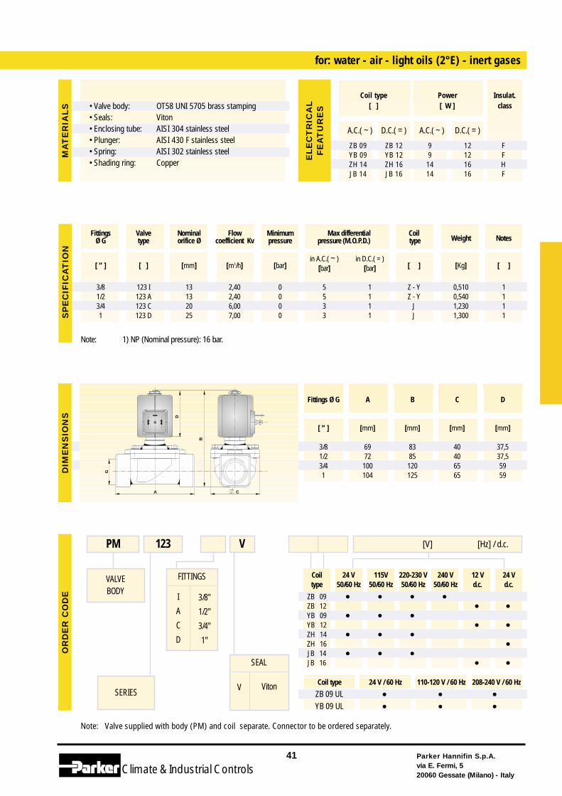
for: water - air - light oils (2°E) - inert gases
VALVEBODY
SERIES
PM 123 [V] [Hz] / d.c.V
SEAL
V Viton
Note: 1) NP (Nominal pressure): 16 bar.
Parker Hannifin S.p.A.via E. Fermi, 520060 Gessate (Milano) - Italy
41
Climate& Industrial Controls
[ ” ] [ ] [mm] [m3/h] [bar]in A.C.( ~ ) in D.C.( = )
[ ] [Kg] [ ][bar] [bar]
3/8 123 I 13 2,40 0 5 1 Z - Y 0,510 1 1/2 123 A 13 2,40 0 5 1 Z - Y 0,540 13/4 123 C 20 6,00 0 3 1 J 1,230 11 123 D 25 7,00 0 3 1 J 1,300 1
Fittings Valve Nominal Flow Minimum Max differential CoilWeight NotesØ G type orifice Ø coefficient Kv pressure pressure (M.O.P.D.) type
G
CA
B
D
SP
EC
IFIC
AT
ION
DIM
EN
SIO
NS
OR
DE
R C
OD
EM
AT
ER
IAL
S
A.C.( ~ ) D.C.( = ) A.C.( ~ ) D.C.( = )
ZB 09 ZB 12 9 12 FYB 09 YB 12 9 12 FZH 14 ZH 16 14 16 HJB 14 JB 16 14 16 F
Coil type Power Insulat.[ ] [ W ] class
EL
EC
TR
ICA
LF
EA
TU
RE
S
Fittings Ø G A B C D
[ ” ] [mm] [mm] [mm] [mm]
3/8 69 83 40 37,51/2 72 85 40 37,53/4 100 120 65 591 104 125 65 59
• Valve body: • Seals:• Enclosing tube:• Plunger:• Spring:• Shading ring:
OT58 UNI 5705 brass stampingVitonAISI 304 stainless steelAISI 430 F stainless steelAISI 302 stainless steelCopper
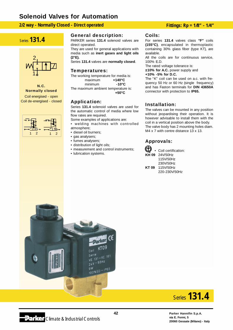
General description:PARKER series 131.4 solenoid valves aredirect operated.They are used for general applications withmedia such as inert gases and light oils(2°E).Series 131.4 valves are normally closed.
Temperatures:The working temperature for media is:
maximum +140°Cminimum -10°C
The maximum ambient temperature is: +50°C
Application:Series 131.4 solenoid valves are used forthe automatic control of media where lowflow rates are required.Some examples of applications are:• welding machines with controlledatmosphere;• diesel oil burners;• gas analysers;• fumes analysers;• distribution of light oils;• measurement and control instruments;• lubrication systems.
Coils:For series 131.4 valves class “F” coils(155°C), encapsulated in thermoplasticcontaining 30% glass fiber (type KT), areavailable.All the coils are for continuous service,100% E.D.The rated voltage tolerance is:±10% for A.C. power supply and+10% -5% for D.C.The “K” coil can be used on a.c. with fre-quency 50 Hz or 60 Hz (single frequency)and has Faston terminals for DIN 43650Aconnector with protection to IP65.
Installation:The valves can be mounted in any positionwithout jeopardising their operation. It ishowever advisable to install them with thecoil in a vertical position above the body.The valve body has 2 mounting holes diam.M4 x 7 with centre distance 13 x 13.
Approvals:
• Coil certification:KH 09 24V/50Hz
115V/50Hz230V/50Hz
KT 09 115V/50Hz220-230V/50Hz
Solenoid Valves for Automation2/2 way - Normally Closed - Direct operated Fittings: Rp = 1/8” - 1/4”
Parker Hannifin S.p.A.via E. Fermi, 520060 Gessate (Milano) - Italy
42
Climate& Industrial Controls
Series 131.4
2121
2
1
N.C.Normally closed
Coil energised - openCoil de-energised - closed
Series 131.4
Coil 24 V 115V 220-230 V 240 V 12 V 24 Vtype 50 Hz* 50 Hz* 50 Hz* 50 Hz* d.c. d.c.
KT 09 • • • •KT 10 • •KH 09 • •
Note: Valve supplied with coil in a multipack. Connector to be ordered separately.
FITTINGS
B
F
G
1/8"
1/4"
1/4"
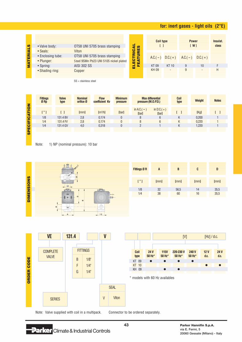
for: inert gases - light oils (2°E)
COMPLETEVALVE
SERIES
VE 131.4 [V] [Hz] / d.c.V
SEAL
V Viton
Note: 1) NP (nominal pressure): 10 bar
Parker Hannifin S.p.A.via E. Fermi, 520060 Gessate (Milano) - Italy
43
Climate& Industrial Controls
[ ” ] [ ] [mm] [m3/h] [bar]in A.C.( ~ ) in D.C.( = )
[ ] [Kg] [ ][bar] [bar]1/8 131.4 BV 2,8 0,174 0 8 6 K 0,200 1 1/4 131.4 FV 2,8 0,174 0 8 6 K 0,220 1 1/4 131.4 GV 4,0 0,318 0 2 1 K 1,220 1
Fittings Valve Nominal Flow Minimum Max differential CoilWeight NotesØ Rp type orifice Ø coefficient Kv pressure pressure (M.O.P.D.) type
R
B
A C
D
M4 x 7
13
13
SP
EC
IFIC
AT
ION
DIM
EN
SIO
NS
OR
DE
R C
OD
EM
AT
ER
IAL
S
A.C.( ~ ) D.C.( = ) A.C.( ~ ) D.C.( = )
KT 09 KT 10 9 10 FKH 09 - 9 - H
Coil type Power Insulat.[ ] [ W ] class
EL
EC
TR
ICA
LF
EA
TU
RE
S
Fittings Ø R A B C D
[ ” ] [mm] [mm] [mm] [mm]
1/8 32 56,5 14 35,51/4 38 60 16 35,5
• Valve body: • Seals:• Enclosing tube:• Plunger:• Spring:• Shading ring:
OT58 UNI 5705 brass stampingVitonOT58 UNI 5705 brass stampingSteel 9SMn Pb23 UNI 5105 nickel platedAISI 302 SSCopper
* models with 60 Hz availables
SS = stainless steel
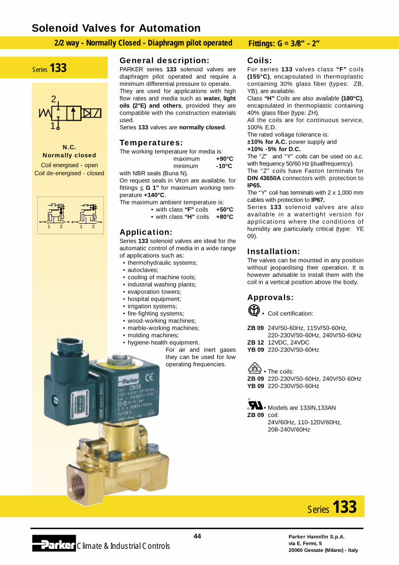
General description:PARKER series 133 solenoid valves arediaphragm pilot operated and require aminimum differential pressure to operate.They are used for applications with highflow rates and media such as water, lightoils (2°E) and others, provided they arecompatible with the construction materialsused.Series 133 valves are normally closed.
Temperatures:The working temperature for media is:
maximum +90°Cminimum -10°C
with NBR seals (Buna N).On request seals in Viton are available, forfittings ≤ G 1” for maximum working tem-perature +140°C.The maximum ambient temperature is:
• with class “F” coils +50°C• with class “H” coils +80°C
Application:Series 133 solenoid valves are ideal for theautomatic control of media in a wide rangeof applications such as:
• thermohydraulic systems;• autoclaves;• cooling of machine tools;• industrial washing plants;• evaporation towers;• hospital equipment;• irrigation systems;• fire-fighting systems;• wood-working machines;• marble-working machines;• molding machines;• hygiene-health equipment.
For air and inert gasesthey can be used for lowoperating frequencies.
Coils:For series 133 valves class “F” coils(155°C), encapsulated in thermoplasticcontaining 30% glass fiber (types: ZB,YB), are available.Class “H” Coils are also available (180°C),encapsulated in thermoplastic containing40% glass fiber (type: ZH).All the coils are for continuous service,100% E.D.The rated voltage tolerance is:±10% for A.C. power supply and+10% -5% for D.C.The “Z” and “Y” coils can be used on a.c.with frequency 50/60 Hz (dualfrequency).The “Z” coils have Faston terminals forDIN 43650A connectors with protection toIP65.The “Y” coil has terminals with 2 x 1,000 mmcables with protection to IP67.Series 133 solenoid valves are alsoavailable in a watertight version forapplications where the conditions ofhumidity are particularly critical (type: YE09).
Installation:The valves can be mounted in any positionwithout jeopardising their operation. It ishowever advisable to install them with thecoil in a vertical position above the body.
Approvals:
• Coil certification:
ZB 09 24V/50-60Hz, 115V/50-60Hz,220-230V/50-60Hz, 240V/50-60Hz
ZB 12 12VDC, 24VDCYB 09 220-230V/50-60Hz
• The coils:ZB 09 220-230V/50-60Hz, 240V/50-60HzYB 09 220-230V/50-60Hz
• Models are 133IN,133AN ZB 09 coil:
24V/60Hz, 110-120V/60Hz,208-240V/60Hz
Solenoid Valves for Automation2/2 way - Normally Closed - Diaphragm pilot operated Fittings: G = 3/8” - 2”
Parker Hannifin S.p.A.via E. Fermi, 520060 Gessate (Milano) - Italy
44
Climate& Industrial Controls
Series 133
2121
2
1
N.C.Normally closed
Coil energised - openCoil de-energised - closed
Series 133
Coil 24 V 115V 220-230 V 240 V 12 V 24 Vtype 50/60 Hz 50/60 Hz 50/60 Hz 50/60 Hz d.c. d.c.
ZB 09 • • • •ZB 12 • •YB 09 • • •YB 12 • •ZH 14 • • •ZH 16 •YE 09 • •
Coil type 24 V / 60 Hz 110-120 V / 60 Hz 208-240 V / 60 Hz
ZB 09 UL • • •YB 09 UL • • •
Note: Valve supplied with body (PM) and coil separate. Connector to be ordered separately. * Optional Viton for fittings up to 1”.
FITTINGS
I
A
C
D
E
F
G
3/8" G
1/2" G
3/4" G
1" G
1 1/4" G
1 1/2" G
2" G
for: water - light oils (2°E)
VALVEBODY
SERIES
PM 133 [V] [Hz] / d.c.
SEAL
N
*VNBR (Buna N)
*Viton
Note: 1) NP (nominal pressure): 25 bar (from 1 1/4 to 3” PN 16 bar). 2) Slow closure version.
Parker Hannifin S.p.A.via E. Fermi, 520060 Gessate (Milano) - Italy
45
Climate& Industrial Controls
[ ” ] [ ] [mm] [m3/h] [bar]in A.C.( ~ ) in D.C.( = )
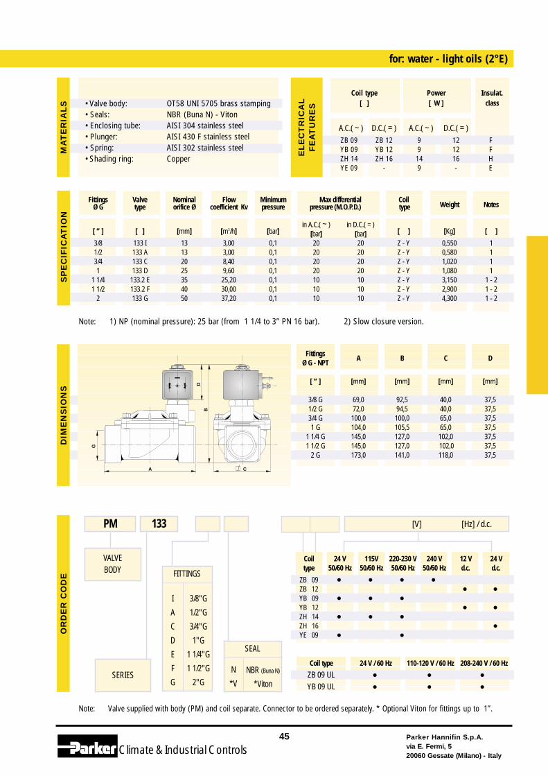
[ ] [Kg] [ ][bar] [bar]3/8 133 I 13 3,00 0,1 20 20 Z - Y 0,550 11/2 133 A 13 3,00 0,1 20 20 Z - Y 0,580 13/4 133 C 20 8,40 0,1 20 20 Z - Y 1,020 11 133 D 25 9,60 0,1 20 20 Z - Y 1,080 1
1 1/4 133.2 E 35 25,20 0,1 10 10 Z - Y 3,150 1 - 21 1/2 133.2 F 40 30,00 0,1 10 10 Z - Y 2,900 1 - 2
2 133 G 50 37,20 0,1 10 10 Z - Y 4,300 1 - 2
Fittings Valve Nominal Flow Minimum Max differential CoilWeight NotesØ G type orifice Ø coefficient Kv pressure pressure (M.O.P.D.) type
G
C
B
A
D
SP
EC
IFIC
AT
ION
DIM
EN
SIO
NS
OR
DE
R C
OD
EM
AT
ER
IAL
S
A.C.( ~ ) D.C.( = ) A.C.( ~ ) D.C.( = )ZB 09 ZB 12 9 12 FYB 09 YB 12 9 12 FZH 14 ZH 16 14 16 HYE 09 - 9 - E
Coil type Power Insulat.[ ] [ W ] class
EL
EC
TR
ICA
LF
EA
TU
RE
S
Fittings A B C D
Ø G - NPT
[ ” ] [mm] [mm] [mm] [mm]
3/8 G 69,0 92,5 40,0 37,51/2 G 72,0 94,5 40,0 37,53/4 G 100,0 100,0 65,0 37,51 G 104,0 105,5 65,0 37,5
1 1/4 G 145,0 127,0 102,0 37,51 1/2 G 145,0 127,0 102,0 37,5
2 G 173,0 141,0 118,0 37,5
• Valve body: • Seals:• Enclosing tube:• Plunger:• Spring:• Shading ring:
OT58 UNI 5705 brass stampingNBR (Buna N) - VitonAISI 304 stainless steelAISI 430 F stainless steelAISI 302 stainless steelCopper
General description:PARKER series 133CMV solenoid valvesare diaphragm pilot operated and require aminimum differential pressure to operate.They are used for applications with highflow rates and media such as water, lightoils (2°E) and others, provided they arecompatible with the construction materialsused.Series 133 valves are normally closed.
Temperatures:The working temperature for media is:
maximum +90°Cminimum -10°C
with NBR seals (Buna N).On request seals in Viton are available, forfittings ≤ G 1” for maximum working tem-perature +140°C.The maximum ambient temperature is:
•with class “F” coils +50°C•with class “H” coils +80°C
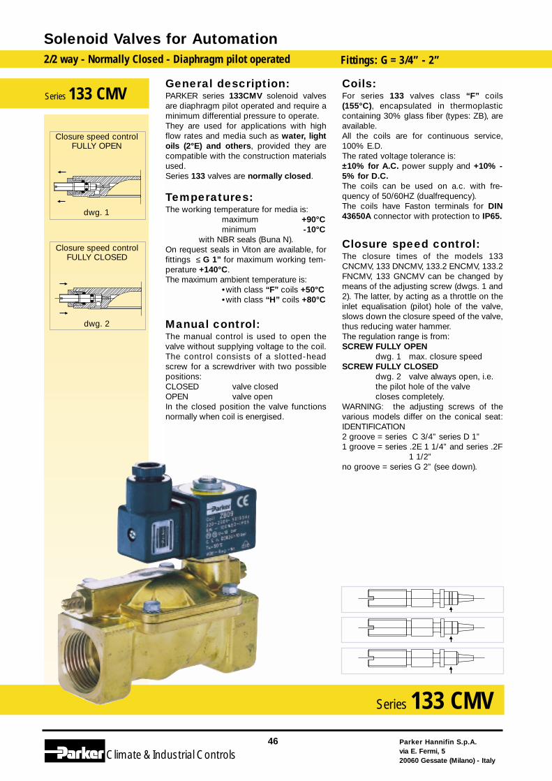
Manual control:The manual control is used to open thevalve without supplying voltage to the coil.The control consists of a slotted-headscrew for a screwdriver with two possiblepositions:CLOSED valve closedOPEN valve openIn the closed position the valve functionsnormally when coil is energised.
Coils:For series 133 valves class “F” coils(155°C), encapsulated in thermoplasticcontaining 30% glass fiber (types: ZB), areavailable.All the coils are for continuous service,100% E.D.The rated voltage tolerance is:±10% for A.C. power supply and +10% -5% for D.C.The coils can be used on a.c. with fre-quency of 50/60HZ (dualfrequency).The coils have Faston terminals for DIN43650A connector with protection to IP65.
Closure speed control:The closure times of the models 133CNCMV, 133 DNCMV, 133.2 ENCMV, 133.2FNCMV, 133 GNCMV can be changed bymeans of the adjusting screw (dwgs. 1 and2). The latter, by acting as a throttle on theinlet equalisation (pilot) hole of the valve,slows down the closure speed of the valve,thus reducing water hammer.The regulation range is from:SCREW FULLY OPEN
dwg. 1 max. closure speedSCREW FULLY CLOSED
dwg. 2 valve always open, i.e. the pilot hole of the valvecloses completely.
WARNING: the adjusting screws of thevarious models differ on the conical seat:IDENTIFICATION2 groove = series C 3/4” series D 1”1 groove = series .2E 1 1/4” and series .2F
1 1/2” no groove = series G 2” (see down).
Solenoid Valves for Automation2/2 way - Normally Closed - Diaphragm pilot operated Fittings: G = 3/4” - 2”
Parker Hannifin S.p.A.via E. Fermi, 520060 Gessate (Milano) - Italy
46
Climate& Industrial Controls
Series 133 CMV
Series 133 CMV
Closure speed controlFULLY CLOSED
dwg. 2
Closure speed controlFULLY OPEN
dwg. 1
Coil 24 V 115V 220-230 V 240 V 12 V 24 Vtype 50/60 Hz 50/60 Hz 50/60 Hz 50/60 Hz d.c. d.c.
ZB 09 • • • •ZB 12 • •YB 09 • • •YB 12 • •ZH 14 • • •ZH 16 •YE 09 • •
Coil type 24 V / 60 Hz 110-120 V / 60 Hz 208-240 V / 60 Hz
ZB 09 UL • • •YB 09 UL • • •
Note: Valve supplied with body (PM) and coil separate. Connector to be ordered separately.
FITTINGS
C
D
E
F
G
L
M
3/4"
1”
1 1/4"
1 1/2"
2"
2 1/2”
3”
for: water - light oils (2°E)
VALVEBODY
SERIES
PM 133 CMV [V] [Hz] / d.c.N
SEAL
MANUALCLOSURE
SPEED CONTROL
N NBR
(Buna N)
Note: 1) NP (nominal pressure): 25 bar. 2) Valve supplied with mechanical part (M.P.) and coil separate.
Parker Hannifin S.p.A.via E. Fermi, 520060 Gessate (Milano) - Italy
47
Climate& Industrial Controls
[ ” ] [ ] [mm] [m3/h] [bar]in A.C.( ~ ) in D.C.( = )
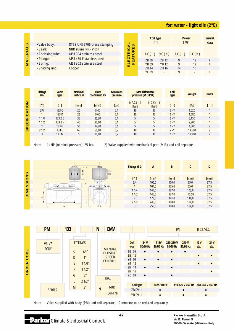
[ ] [Kg] [ ][bar] [bar]3/4 133 C 20 8,40 0,1 10 10 Z - Y 1,020 1 1 133 D 25 9,60 0,1 10 10 Z - Y 1,080 1
1 1/4 133.2 E 35 25,20 0,1 5 5 Z - Y 3,150 1 1 1/2 133.2 F 40 30,00 0,1 5 5 Z - Y 2,900 1
2 133 G 50 37,20 0,1 5 5 Z - Y 4,300 22 1/2 133 L 65 66,00 0,2 10 10 Z -Y 13,600 2
3 133 M 75 80,00 0,2 10 10 Z - Y 11,900 2
Fittings Valve Nominal Flow Minimum Max differential CoilWeight NotesØ G type orifice Ø coefficient Kv pressure pressure (M.O.P.D.) type
G
C
B
A
D=
37
C
A
SP
EC
IFIC
AT
ION
DIM
EN
SIO
NS
OR
DE
R C
OD
EM
AT
ER
IAL
S
A.C.( ~ ) D.C.( = ) A.C.( ~ ) D.C.( = )
ZB 09 ZB 12 9 12 FYB 09 YB 12 9 12 FZH 14 ZH 16 14 16 HYE 09 - 9 - E
Coil type Power Insulat.[ ] [ W ] class
EL
EC
TR
ICA
LF
EA
TU
RE
S
Fittings Ø G A B C D
[ ” ] [mm] [mm] [mm] [mm]3/4 100,0 100,0 65,0 37,51 104,0 105,0 65,0 37,5
1 1/4 145,0 127,0 102,0 37,51 1/2 145,0 127,0 102,0 37,5
2 173,0 141,0 118,0 37,52 1/2 245,0 188,0 184,0 37,5
3 250,0 188,0 184,0 37,5
• Valve body: • Seals:• Enclosing tube:• Plunger:• Spring:• Shading ring:
OT58 UNI 5705 brass stampingNBR (Buna N) - VitonAISI 304 stainless steelAISI 430 F stainless steelAISI 302 stainless steelCopper
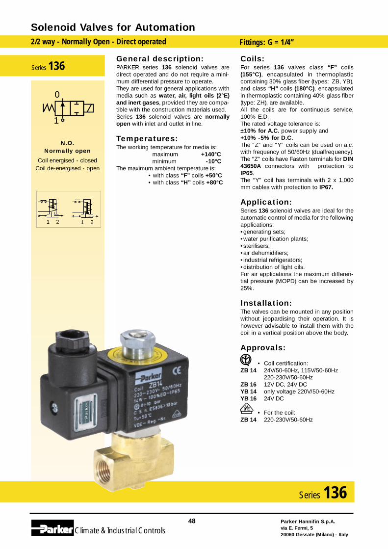
General description:PARKER series 136 solenoid valves aredirect operated and do not require a mini-mum differential pressure to operate.They are used for general applications withmedia such as water, air, light oils (2°E)and inert gases, provided they are compa-tible with the construction materials used.Series 136 solenoid valves are normallyopen with inlet and outlet in line.
Temperatures:The working temperature for media is:
maximum +140°Cminimum -10°C
The maximum ambient temperature is:• with class “F” coils +50°C• with class “H” coils +80°C
Coils:For series 136 valves class “F” coils(155°C), encapsulated in thermoplasticcontaining 30% glass fiber (types: ZB, YB),and class “H” coils (180°C), encapsulatedin thermoplastic containing 40% glass fiber(type: ZH), are available.All the coils are for continuous service,100% E.D.The rated voltage tolerance is:±10% for A.C. power supply and+10% -5% for D.C.The “Z” and “Y” coils can be used on a.c.with frequency of 50/60Hz (dualfrequency).The “Z” coils have Faston terminals for DIN43650A connectors with protection toIP65.The “Y” coil has terminals with 2 x 1,000mm cables with protection to IP67.
Application:Series 136 solenoid valves are ideal for theautomatic control of media for the followingapplications:•generating sets;•water purification plants;•sterilisers;•air dehumidifiers;•industrial refrigerators;•distribution of light oils.For air applications the maximum differen-tial pressure (MOPD) can be increased by25%.
Installation:The valves can be mounted in any positionwithout jeopardising their operation. It ishowever advisable to install them with thecoil in a vertical position above the body.
Approvals:
• Coil certification:ZB 14 24V/50-60Hz, 115V/50-60Hz
220-230V/50-60HzZB 16 12V DC, 24V DC YB 14 only voltage 220V/50-60HzYB 16 24V DC
• For the coil:ZB 14 220-230V/50-60Hz
Solenoid Valves for Automation2/2 way - Normally Open - Direct operated Fittings: G = 1/4”
Parker Hannifin S.p.A.via E. Fermi, 520060 Gessate (Milano) - Italy
48
Climate& Industrial Controls
Series 136
2121
0
1
N.O.Normally open
Coil energised - closedCoil de-energised - open
Series 136
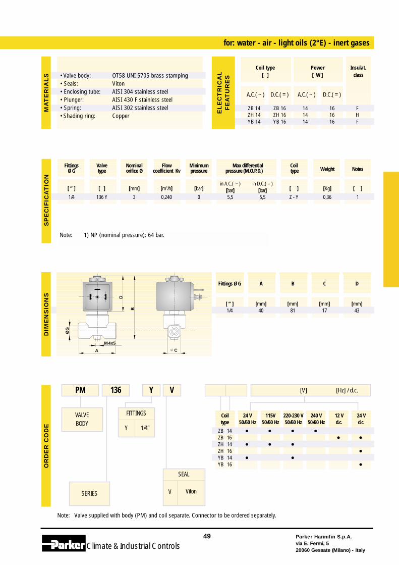
Coil 24 V 115V 220-230 V 240 V 12 V 24 Vtype 50/60 Hz 50/60 Hz 50/60 Hz 50/60 Hz d.c. d.c.
ZB 14 • • • •ZB 16 • •ZH 14 • • •ZH 16 •YB 14 • •YB 16 •
Note: Valve supplied with body (PM) and coil separate. Connector to be ordered separately.
FITTINGS
Y 1/4”
for: water - air - light oils (2°E) - inert gases
VALVEBODY
SERIES
PM 136 Y [V] [Hz] / d.c.V
SEAL
V Viton
Parker Hannifin S.p.A.via E. Fermi, 520060 Gessate (Milano) - Italy
49
Climate& Industrial Controls
[ ” ] [ ] [mm] [m3/h] [bar]in A.C.( ~ ) in D.C.( = )
[ ] [Kg] [ ][bar] [bar]1/4 136 Y 3 0,240 0 5,5 5,5 Z - Y 0,36 1
Fittings Valve Nominal Flow Minimum Max differential CoilWeight NotesØ G type orifice Ø coefficient Kv pressure pressure (M.O.P.D.) type
ØG
B
CA
D
M4x5
SP
EC
IFIC
AT
ION
DIM
EN
SIO
NS
OR
DE
R C
OD
EM
AT
ER
IAL
S
A.C.( ~ ) D.C.( = ) A.C.( ~ ) D.C.( = )
ZB 14 ZB 16 14 16 FZH 14 ZH 16 14 16 HYB 14 YB 16 14 16 F
Coil type Power Insulat.[ ] [ W ] class
EL
EC
TR
ICA
LF
EA
TU
RE
S
Fittings Ø G A B C D
[ ” ] [mm] [mm] [mm] [mm]1/4 40 81 17 43
• Valve body: • Seals:• Enclosing tube:• Plunger:• Spring:• Shading ring:
OT58 UNI 5705 brass stampingVitonAISI 304 stainless steelAISI 430 F stainless steelAISI 302 stainless steelCopper
Note: 1) NP (nominal pressure): 64 bar.
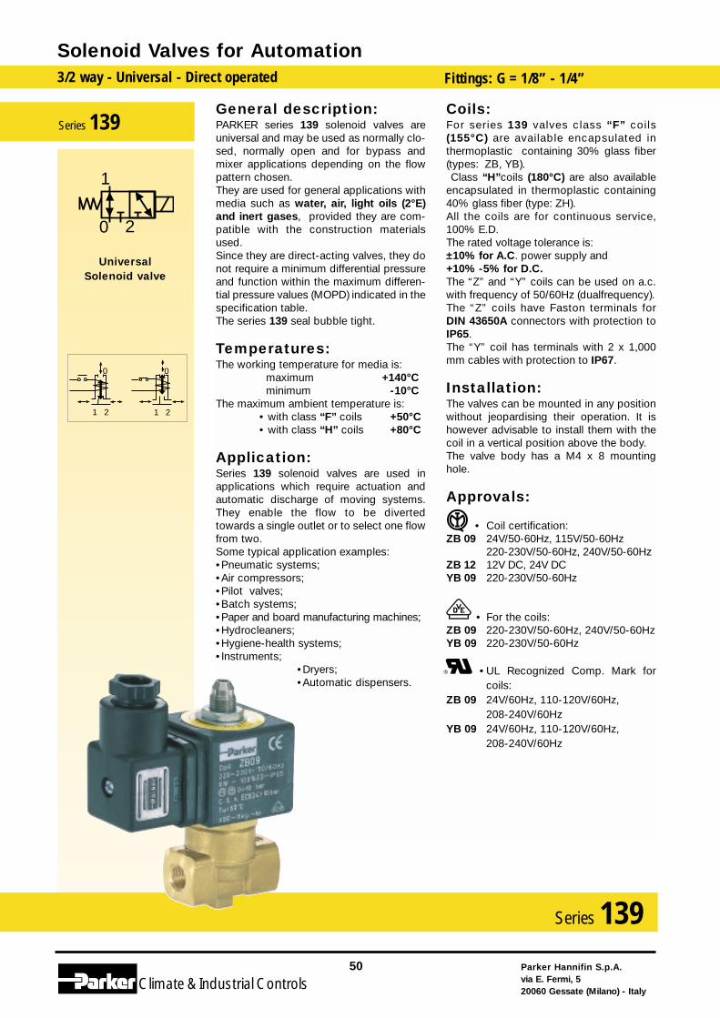
General description:PARKER series 139 solenoid valves areuniversal and may be used as normally clo-sed, normally open and for bypass andmixer applications depending on the flowpattern chosen.They are used for general applications withmedia such as water, air, light oils (2°E)and inert gases, provided they are com-patible with the construction materialsused.Since they are direct-acting valves, they donot require a minimum differential pressureand function within the maximum differen-tial pressure values (MOPD) indicated in thespecification table.The series 139 seal bubble tight.
Temperatures:The working temperature for media is:
maximum +140°Cminimum -10°C
The maximum ambient temperature is:• with class “F” coils +50°C• with class “H” coils +80°C
Application:Series 139 solenoid valves are used inapplications which require actuation andautomatic discharge of moving systems.They enable the flow to be divertedtowards a single outlet or to select one flowfrom two.Some typical application examples:•Pneumatic systems;•Air compressors;•Pilot valves;•Batch systems;•Paper and board manufacturing machines;•Hydrocleaners;•Hygiene-health systems;•Instruments;
•Dryers;•Automatic dispensers.
Coils:For series 139 valves class “F” coils(155°C) are available encapsulated inthermoplastic containing 30% glass fiber(types: ZB, YB).Class “H”coils (180°C) are also available
encapsulated in thermoplastic containing40% glass fiber (type: ZH).All the coils are for continuous service,100% E.D.The rated voltage tolerance is:±10% for A.C. power supply and+10% -5% for D.C.The “Z” and “Y” coils can be used on a.c.with frequency of 50/60Hz (dualfrequency).The “Z” coils have Faston terminals forDIN 43650A connectors with protection toIP65.The “Y” coil has terminals with 2 x 1,000mm cables with protection to IP67.
Installation:The valves can be mounted in any positionwithout jeopardising their operation. It ishowever advisable to install them with thecoil in a vertical position above the body.The valve body has a M4 x 8 mountinghole.
Approvals:
• Coil certification:ZB 09 24V/50-60Hz, 115V/50-60Hz
220-230V/50-60Hz, 240V/50-60HzZB 12 12V DC, 24V DC YB 09 220-230V/50-60Hz
• For the coils:ZB 09 220-230V/50-60Hz, 240V/50-60HzYB 09 220-230V/50-60Hz
•UL Recognized Comp. Mark forcoils:
ZB 09 24V/60Hz, 110-120V/60Hz, 208-240V/60Hz
YB 09 24V/60Hz, 110-120V/60Hz, 208-240V/60Hz
Solenoid Valves for Automation3/2 way - Universal - Direct operated Fittings: G = 1/8” - 1/4”
Parker Hannifin S.p.A.via E. Fermi, 520060 Gessate (Milano) - Italy
50
Climate& Industrial Controls
Series 139
21
0
21
0
2
1
0
UniversalSolenoid valve
Series 139
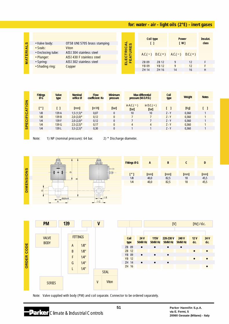
Coil 24 V 115V 220-230 V 240 V 12 V 24 Vtype 50/60 Hz 50/60 Hz 50/60 Hz 50/60 Hz d.c. d.c.
ZB 09 • • • •ZB 12 • •YB 09 • • •YB 12 • •ZH 14 • • •ZH 16 •
Note: Valve supplied with body (PM) and coil separate. Connector to be ordered separately.
FITTINGS
A
B
F
G
L
1/8"
1/8"
1/4"
1/4"
1/4"
for: water - air - light oils (2°E) - inert gases
VALVEBODY
SERIES
PM 139 [V] [Hz] / d.c.V
SEAL
V Viton
Note: 1) NP (nominal pressure): 64 bar. 2) * Discharge diameter.
Parker Hannifin S.p.A.via E. Fermi, 520060 Gessate (Milano) - Italy
51
Climate& Industrial Controls
[ ” ] [ ] [mm] [m3/h] [bar]in A.C.( ~ ) in D.C.( = )
[ ] [Kg] [ ][bar] [bar]1/8 139 A 1,5 (1,5)* 0,07 0 10 10 Z - Y 0,360 11/8 139 B 2,0 (2,0)* 0,12 0 7 7 Z - Y 0,360 1 1/4 139 F 2,0 (2,0)* 0,12 0 7 7 Z - Y 0,360 1 1/4 139 G 2,5 (2,5)* 0,17 0 4 4 Z - Y 0,360 1 1/4 139 L 3,5 (2,5)* 0,30 0 1 1 Z - Y 0,360 1
Fittings Valve Nominal Flow Minimum Max differential CoilWeight NotesØ G type orifice Ø coefficient Kv pressure pressure (M.O.P.D.) type
G
B
D
CA4MAx8 8
SP
EC
IFIC
AT
ION
DIM
EN
SIO
NS
OR
DE
R C
OD
EM
AT
ER
IAL
S
A.C.( ~ ) D.C.( = ) A.C.( ~ ) D.C.( = )
ZB 09 ZB 12 9 12 FYB 09 YB 12 9 12 FZH 14 ZH 16 14 16 H
Coil type Power Insulat.[ ] [ W ] class
EL
EC
TR
ICA
LF
EA
TU
RE
S
Fittings Ø G A B C D
[ ” ] [mm] [mm] [mm] [mm]1/8 40,0 82,5 18 45,51/4 40,0 82,5 18 45,5
• Valve body: • Seals:• Enclosing tube:• Plunger:• Spring:• Shading ring:
OT58 UNI 5705 brass stampingVitonAISI 304 stainless steelAISI 430 F stainless steelAISI 302 stainless steelCopper
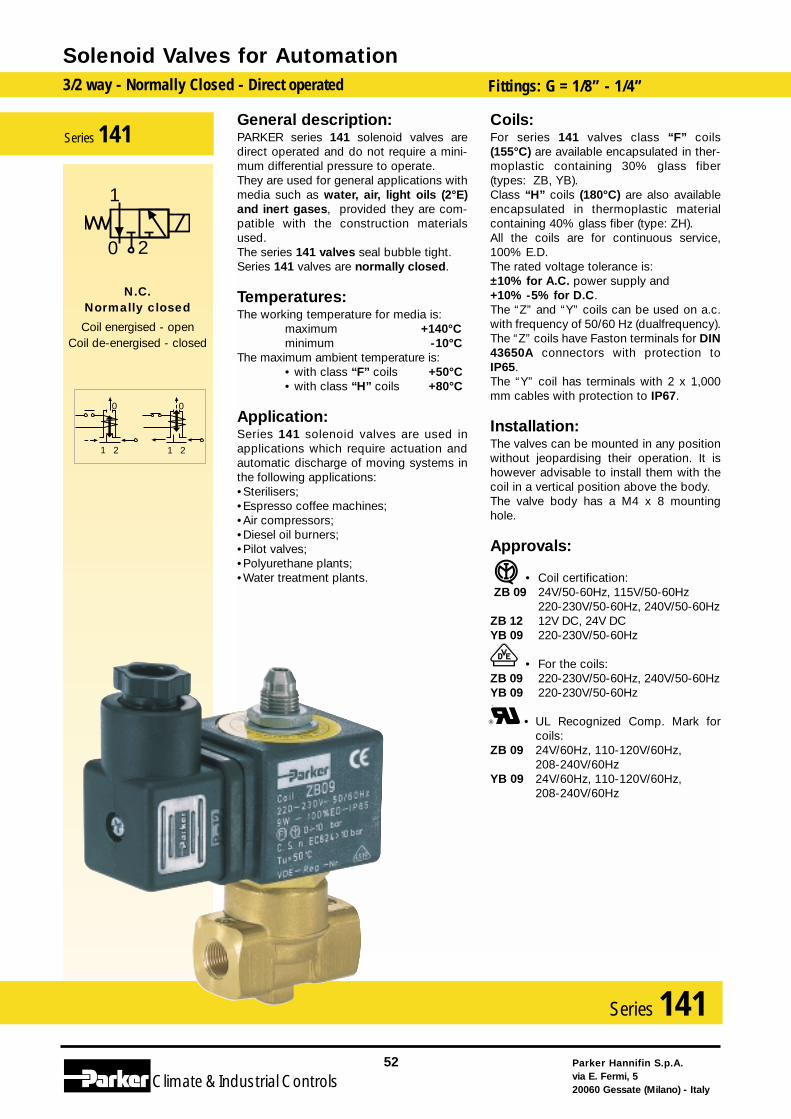
General description:PARKER series 141 solenoid valves aredirect operated and do not require a mini-mum differential pressure to operate.They are used for general applications withmedia such as water, air, light oils (2°E)and inert gases, provided they are com-patible with the construction materialsused.The series 141 valves seal bubble tight.Series 141 valves are normally closed.
Temperatures:The working temperature for media is:
maximum +140°Cminimum -10°C
The maximum ambient temperature is:• with class “F” coils +50°C• with class “H” coils +80°C
Application:Series 141 solenoid valves are used inapplications which require actuation andautomatic discharge of moving systems inthe following applications:•Sterilisers;•Espresso coffee machines;•Air compressors;•Diesel oil burners;•Pilot valves;•Polyurethane plants;•Water treatment plants.
Coils:For series 141 valves class “F” coils(155°C) are available encapsulated in ther-moplastic containing 30% glass fiber(types: ZB, YB).Class “H” coils (180°C) are also availableencapsulated in thermoplastic materialcontaining 40% glass fiber (type: ZH).All the coils are for continuous service,100% E.D.The rated voltage tolerance is:±10% for A.C. power supply and+10% -5% for D.C.The “Z” and “Y” coils can be used on a.c.with frequency of 50/60 Hz (dualfrequency).The “Z” coils have Faston terminals for DIN43650A connectors with protection toIP65.The “Y” coil has terminals with 2 x 1,000mm cables with protection to IP67.
Installation:The valves can be mounted in any positionwithout jeopardising their operation. It ishowever advisable to install them with thecoil in a vertical position above the body.The valve body has a M4 x 8 mountinghole.
Approvals:
• Coil certification:ZB 09 24V/50-60Hz, 115V/50-60Hz
220-230V/50-60Hz, 240V/50-60HzZB 12 12V DC, 24V DC YB 09 220-230V/50-60Hz
• For the coils:ZB 09 220-230V/50-60Hz, 240V/50-60HzYB 09 220-230V/50-60Hz
• UL Recognized Comp. Mark forcoils:
ZB 09 24V/60Hz, 110-120V/60Hz, 208-240V/60Hz
YB 09 24V/60Hz, 110-120V/60Hz, 208-240V/60Hz
Solenoid Valves for Automation3/2 way - Normally Closed - Direct operated Fittings: G = 1/8” - 1/4”
Parker Hannifin S.p.A.via E. Fermi, 520060 Gessate (Milano) - Italy
52
Climate& Industrial Controls
Series 141
21
0
21
0
2
1
0
N.C.Normally closed
Coil energised - openCoil de-energised - closed
Series 141
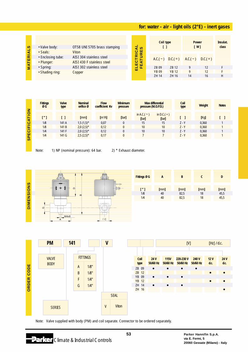
Coil 24 V 115V 220-230 V 240 V 12 V 24 Vtype 50/60 Hz 50/60 Hz 50/60 Hz 50/60 Hz d.c. d.c.
ZB 09 • • • •ZB 12 • •YB 09 • • •YB 12 • •ZH 14 • • •ZH 16 •
Note: Valve supplied with body (PM) and coil separate. Connector to be ordered separately.
FITTINGS
A
B
F
G
1/8"
1/8"
1/4"
1/4"
for: water - air - light oils (2°E) - inert gases
VALVEBODY
SERIES
PM 141 [V] [Hz] / d.c.V
SEAL
V Viton
Note: 1) NP (nominal pressure): 64 bar. 2) * Exhaust diameter.
Parker Hannifin S.p.A.via E. Fermi, 520060 Gessate (Milano) - Italy
53
Climate& Industrial Controls
[ ” ] [ ] [mm] [m3/h] [bar]in A.C.( ~ ) in D.C.( = )
[ ] [Kg] [ ][bar] [bar]1/8 141 A 1,5 (1,5)* 0,07 0 15 15 Z - Y 0,360 11/8 141 B 2,0 (2,5)* 0,12 0 10 10 Z - Y 0,360 1 1/4 141 F 2,0 (2,5)* 0,12 0 10 10 Z - Y 0,360 1 1/4 141 G 2,5 (2,5)* 0,17 0 7 7 Z - Y 0,360 1
Fittings Valve Nominal Flow Minimum Max differential CoilWeight NotesØ G type orifice Ø coefficient Kv pressure pressure (M.O.P.D.) type
G
B
CA
D
M4x8
SP
EC
IFIC
AT
ION
DIM
EN
SIO
NS
OR
DE
R C
OD
EM
AT
ER
IAL
S
A.C.( ~ ) D.C.( = ) A.C.( ~ ) D.C.( = )
ZB 09 ZB 12 9 12 FYB 09 YB 12 9 12 FZH 14 ZH 16 14 16 H
Coil type Power Insulat.[ ] [ W ] class
EL
EC
TR
ICA
LF
EA
TU
RE
S
Fittings Ø G A B C D
[ ” ] [mm] [mm] [mm] [mm]1/8 40 82,5 18 45,51/4 40 82,5 18 45,5
• Valve body: • Seals:• Enclosing tube:• Plunger:• Spring:• Shading ring:
OT58 UNI 5705 brass stampingVitonAISI 304 stainless steelAISI 430 F stainless steelAISI 302 stainless steelCopper
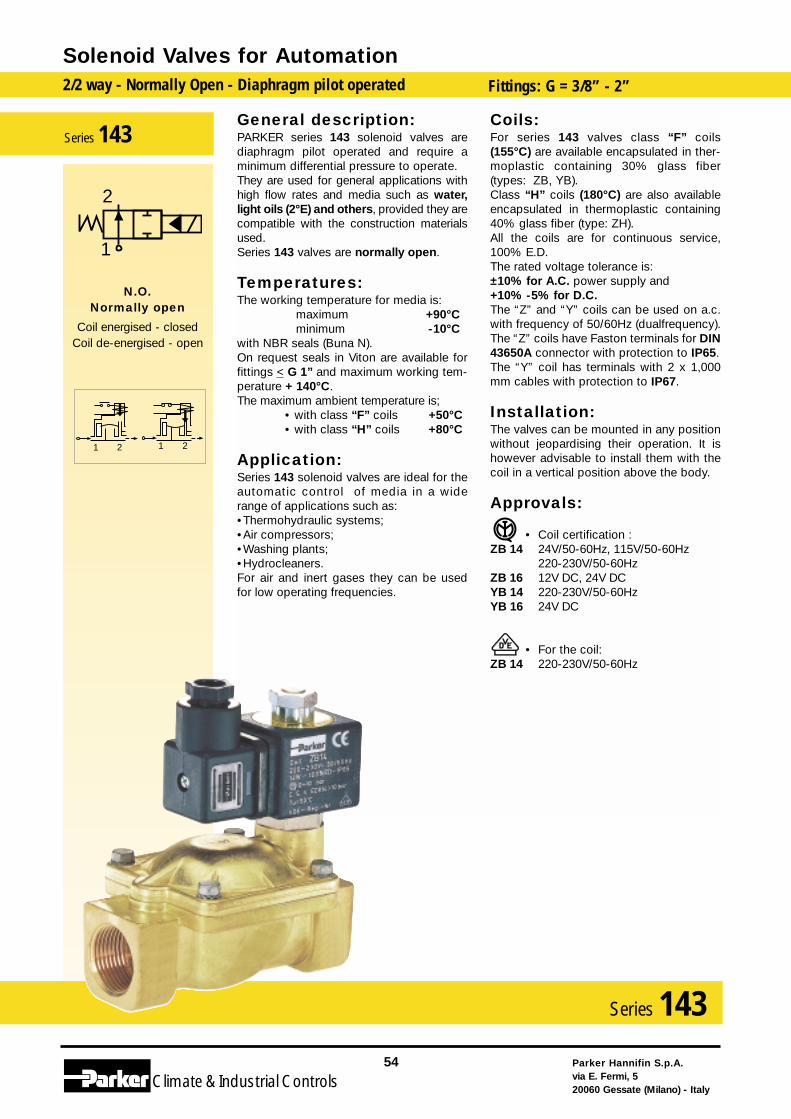
General description:PARKER series 143 solenoid valves arediaphragm pilot operated and require aminimum differential pressure to operate.They are used for general applications withhigh flow rates and media such as water,light oils (2°E) and others, provided they arecompatible with the construction materialsused.Series 143 valves are normally open.
Temperatures:The working temperature for media is:
maximum +90°Cminimum -10°C
with NBR seals (Buna N).On request seals in Viton are available forfittings < G 1” and maximum working tem-perature + 140°C.The maximum ambient temperature is;
• with class “F” coils +50°C• with class “H” coils +80°C
Application:Series 143 solenoid valves are ideal for theautomatic control of media in a widerange of applications such as:•Thermohydraulic systems;•Air compressors;•Washing plants;•Hydrocleaners.For air and inert gases they can be usedfor low operating frequencies.
Coils:For series 143 valves class “F” coils(155°C) are available encapsulated in ther-moplastic containing 30% glass fiber(types: ZB, YB).Class “H” coils (180°C) are also availableencapsulated in thermoplastic containing40% glass fiber (type: ZH).All the coils are for continuous service,100% E.D.The rated voltage tolerance is:±10% for A.C. power supply and+10% -5% for D.C.The “Z” and “Y” coils can be used on a.c.with frequency of 50/60Hz (dualfrequency).The “Z” coils have Faston terminals for DIN43650A connector with protection to IP65.The “Y” coil has terminals with 2 x 1,000mm cables with protection to IP67.
Installation:The valves can be mounted in any positionwithout jeopardising their operation. It ishowever advisable to install them with thecoil in a vertical position above the body.
Approvals:
• Coil certification :ZB 14 24V/50-60Hz, 115V/50-60Hz
220-230V/50-60HzZB 16 12V DC, 24V DC YB 14 220-230V/50-60HzYB 16 24V DC
• For the coil:ZB 14 220-230V/50-60Hz
Solenoid Valves for Automation2/2 way - Normally Open - Diaphragm pilot operated Fittings: G = 3/8” - 2”
Parker Hannifin S.p.A.via E. Fermi, 520060 Gessate (Milano) - Italy
54
Climate& Industrial Controls
Series 143
2121
2
1
N.O.Normally open
Coil energised - closedCoil de-energised - open
Series 143
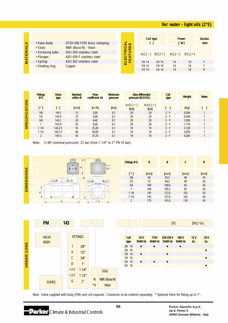
Coil 24 V 115V 220-230 V 240 V 12 V 24 Vtype 50/60 Hz 50/60 Hz 50/60 Hz 50/60 Hz d.c. d.c.
ZB 14 • • • •ZB 16 •YB 14 • •YB 16 •ZH 14 • • •ZH 16 •
Note: Valve supplied with body (PM) and coil separate. Connector to be ordered separately. * Optional Viton for fitting up to 1”.
FITTINGS
I
A
C
D
• 2 E
• 2 F
G
3/8"
1/2"
3/4"
1"
1 1/4"
1 1/2"
2"
for: water - light oils (2°E)
VALVEBODY
SERIES
PM 143 [V] [Hz] / d.c.
SEAL
N
*V
NBR (Buna N)
Viton
Note: 1) NP (nominal pressure): 25 bar (from 1 1/4” to 2” PN 16 bar).
Parker Hannifin S.p.A.via E. Fermi, 520060 Gessate (Milano) - Italy
55
Climate& Industrial Controls
[ ” ] [ ] [mm] [m3/h] [bar]in A.C.( ~ ) in D.C.( = )
[ ] [Kg] [ ][bar] [bar]3/8 143 I 13 3,00 0,1 20 20 Z - Y 0,560 11/2 143 A 13 3,00 0,1 20 20 Z - Y 0,590 13/4 143 C 20 8,40 0,1 20 20 Z - Y 1,050 11 143 D 25 9,60 0,1 20 20 Z - Y 1,110 1
1 1/4 143.2 E 35 25,20 0,1 10 10 Z - Y 3,120 11 1/2 143.2 F 40 30,00 0,1 10 10 Z - Y 2,870 1
2 143 G 50 37,20 0,1 10 10 Z - Y 4,260 1
Fittings Valve Nominal Flow Minimum Max differential CoilWeight NotesØ G type orifice Ø coefficient Kv pressure pressure (M.O.P.D.) type
G
C
B
A
D
SP
EC
IFIC
AT
ION
DIM
EN
SIO
NS
OR
DE
R C
OD
EM
AT
ER
IAL
S
A.C.( ~ ) D.C.( = ) A.C.( ~ ) D.C.( = )
ZB 14 ZB 16 14 16 FYB 14 YB 16 14 16 FZH 14 ZH 16 14 16 H
Coil type Power Insulat.[ ] [ W ] class
EL
EC
TR
ICA
LF
EA
TU
RE
S
Fittings Ø G A B C D
[ ” ] [mm] [mm] [mm] [mm]3/8 69 92,5 40 431/2 72 94,5 40 433/4 100 100,0 65 431 104 105,5 65 43
1 1/4 145 127,0 102 431 1/2 145 127,0 102 43
2 173 141,0 118 43
• Valve body: • Seals:• Enclosing tube:• Plunger:• Spring:• Shading ring:
OT58 UNI 5705 brass stampingNBR (Buna N) - VitonAISI 304 stainless steelAISI 430 F stainless steelAISI 302 stainless steelCopper
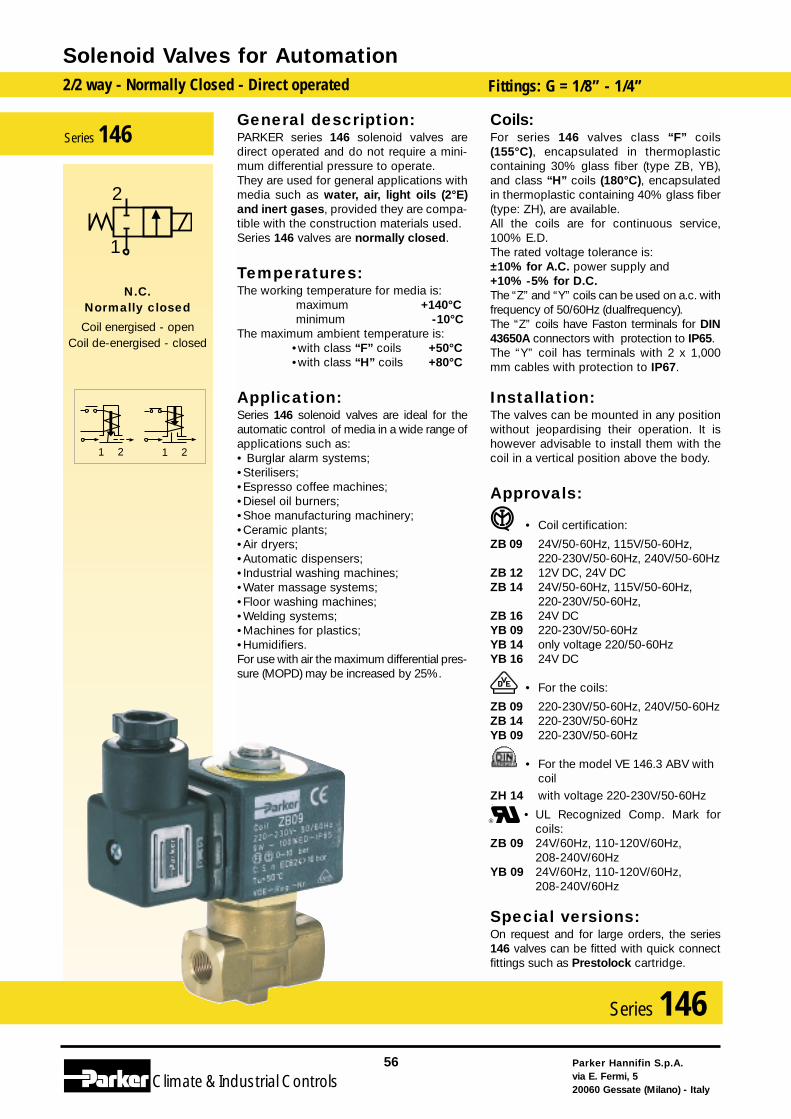
General description:PARKER series 146 solenoid valves aredirect operated and do not require a mini-mum differential pressure to operate.They are used for general applications withmedia such as water, air, light oils (2°E)and inert gases, provided they are compa-tible with the construction materials used.Series 146 valves are normally closed.
Temperatures:The working temperature for media is:
maximum +140°Cminimum -10°C
The maximum ambient temperature is:•with class “F” coils +50°C•with class “H” coils +80°C
Application:Series 146 solenoid valves are ideal for theautomatic control of media in a wide range ofapplications such as:• Burglar alarm systems;•Sterilisers;•Espresso coffee machines;•Diesel oil burners;•Shoe manufacturing machinery;•Ceramic plants;•Air dryers;•Automatic dispensers;•Industrial washing machines;•Water massage systems;•Floor washing machines;•Welding systems;•Machines for plastics;•Humidifiers.For use with air the maximum differential pres-sure (MOPD) may be increased by 25%.
Coils:For series 146 valves class “F” coils(155°C), encapsulated in thermoplasticcontaining 30% glass fiber (type ZB, YB),and class “H” coils (180°C), encapsulatedin thermoplastic containing 40% glass fiber(type: ZH), are available.All the coils are for continuous service,100% E.D.The rated voltage tolerance is:±10% for A.C. power supply and+10% -5% for D.C.The “Z” and “Y” coils can be used on a.c. withfrequency of 50/60Hz (dualfrequency).The “Z” coils have Faston terminals for DIN43650A connectors with protection to IP65.The “Y” coil has terminals with 2 x 1,000mm cables with protection to IP67.
Installation:The valves can be mounted in any positionwithout jeopardising their operation. It ishowever advisable to install them with thecoil in a vertical position above the body.
Approvals:
• Coil certification:
ZB 09 24V/50-60Hz, 115V/50-60Hz,220-230V/50-60Hz, 240V/50-60Hz
ZB 12 12V DC, 24V DCZB 14 24V/50-60Hz, 115V/50-60Hz,
220-230V/50-60Hz, ZB 16 24V DCYB 09 220-230V/50-60HzYB 14 only voltage 220/50-60HzYB 16 24V DC
• For the coils:
ZB 09 220-230V/50-60Hz, 240V/50-60HzZB 14 220-230V/50-60HzYB 09 220-230V/50-60Hz
• For the model VE 146.3 ABV withcoil
ZH 14 with voltage 220-230V/50-60Hz
• UL Recognized Comp. Mark forcoils:
ZB 09 24V/60Hz, 110-120V/60Hz, 208-240V/60Hz
YB 09 24V/60Hz, 110-120V/60Hz, 208-240V/60Hz
Special versions:On request and for large orders, the series146 valves can be fitted with quick connectfittings such as Prestolock cartridge.
Solenoid Valves for Automation2/2 way - Normally Closed - Direct operated Fittings: G = 1/8” - 1/4”
Parker Hannifin S.p.A.via E. Fermi, 520060 Gessate (Milano) - Italy
56
Climate& Industrial Controls
Series 146
2121
2
1
N.C.Normally closed
Coil energised - openCoil de-energised - closed
Series 146
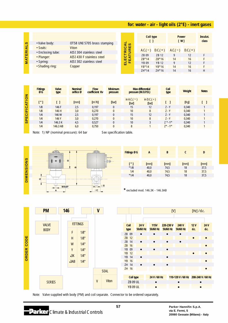
Coil 24 V 115V 220-230 V 240 V 12 V 24 Vtype 50/60 Hz 50/60 Hz 50/60 Hz 50/60 Hz d.c. d.c.
ZB 09 • • • •ZB 12 • •ZB 14 • • • •ZB 16 •YB 09 • • •YB 12 • •YB 14 • •YB 16 •ZH 14 • • •ZH 16 •
Coil type 24 V / 60 Hz 110-120 V / 60 Hz 208-240 V / 60 Hz
ZB 09 UL • • •YB 09 UL • • •
Note: Valve supplied with body (PM) and coil separate. Connector to be ordered separately.
FITTINGS
F
H
W
Y
•3K
•3AB
1/8"
1/8"
1/4"
1/4"
1/4"
1/4"
for: water - air - light oils (2°E) - inert gases
VALVEBODY
SERIES
PM 146 [V] [Hz] / d.c.V
SEAL
V Viton
Note: 1) NP (nominal pressure): 64 bar See specification table.
* excluded mod. 146.3K - 146.3AB
Parker Hannifin S.p.A.via E. Fermi, 520060 Gessate (Milano) - Italy
57
Climate& Industrial Controls
[ ” ] [ ] [mm] [m3/h] [bar]in A.C.( ~ ) in D.C.( = )
[ ] [Kg] [ ][bar] [bar]1/8 146 F 2,5 0,197 0 15 12 Z - Y 0,340 11/8 146 H 3,0 0,270 0 10 8 Z - Y 0,340 11/4 146 W 2,5 0,197 0 15 12 Z - Y 0,340 11/4 146 Y 3,0 0,270 0 10 8 Z - Y 0,340 11/4 146.3 K 4,5 0,527 0 10 3 Z *- Y* 0,340 11/4 146.3 AB 6,0 0,750 0 8 1 Z* - Y* 0,340 1
Fittings Valve Nominal Flow Minimum Max differential CoilWeight NotesØ G type orifice Ø coefficient Kv pressure pressure (M.O.P.D.) type
G
B
A C
D
M4x8* 8
SP
EC
IFIC
AT
ION
DIM
EN
SIO
NS
OR
DE
R C
OD
EM
AT
ER
IAL
S
Fittings Ø G A B C D
[ ” ] [mm] [mm] [mm] [mm]*1/8 40,0 74,5 18 37,51/4 40,0 74,5 18 37,5
*1/4 40,0 74,5 18 37,5
A.C.( ~ ) D.C.( = ) A.C.( ~ ) D.C.( = )ZB 09 ZB 12 9 12 FZB*14 ZB*16 14 16 FYB 09 YB 12 9 12 FYB*14 YB*16 14 16 FZH*14 ZH*16 14 16 H
Coil type Power Insulat.[ ] [ W ] class
EL
EC
TR
ICA
LF
EA
TU
RE
S• Valve body: • Seals:• Enclosing tube:• Plunger:• Spring:• Shading ring:
OT58 UNI 5705 brass stampingVitonAISI 304 stainless steelAISI 430 F stainless steelAISI 302 stainless steelCopper
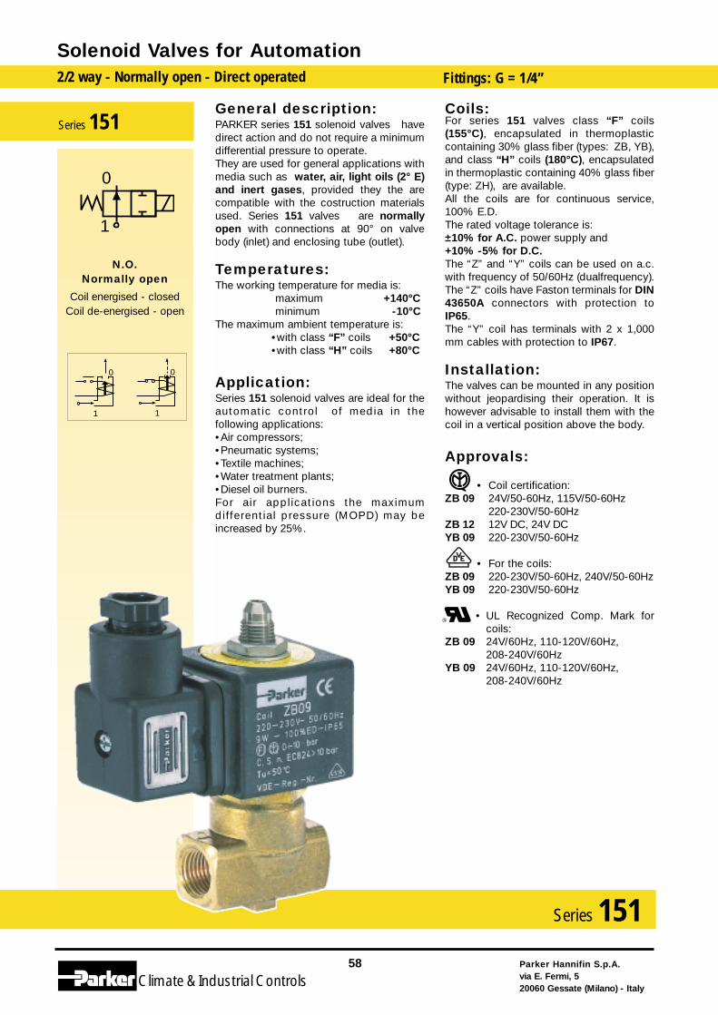
General description:PARKER series 151 solenoid valves havedirect action and do not require a minimumdifferential pressure to operate.They are used for general applications withmedia such as water, air, light oils (2° E)and inert gases, provided they the arecompatible with the costruction materialsused. Series 151 valves are normallyopen with connections at 90° on valvebody (inlet) and enclosing tube (outlet).
Temperatures:The working temperature for media is:
maximum +140°Cminimum -10°C
The maximum ambient temperature is:•with class “F” coils +50°C•with class “H” coils +80°C
Application:Series 151 solenoid valves are ideal for theautomatic control of media in thefollowing applications:•Air compressors;•Pneumatic systems;•Textile machines;•Water treatment plants;•Diesel oil burners.For air applications the maximumdifferential pressure (MOPD) may beincreased by 25%.
Coils:For series 151 valves class “F” coils(155°C), encapsulated in thermoplasticcontaining 30% glass fiber (types: ZB, YB),and class “H” coils (180°C), encapsulatedin thermoplastic containing 40% glass fiber(type: ZH), are available.All the coils are for continuous service,100% E.D.The rated voltage tolerance is:±10% for A.C. power supply and+10% -5% for D.C.The “Z” and “Y” coils can be used on a.c.with frequency of 50/60Hz (dualfrequency).The “Z” coils have Faston terminals for DIN43650A connectors with protection toIP65.The “Y” coil has terminals with 2 x 1,000mm cables with protection to IP67.
Installation:The valves can be mounted in any positionwithout jeopardising their operation. It ishowever advisable to install them with thecoil in a vertical position above the body.
Approvals:
• Coil certification:ZB 09 24V/50-60Hz, 115V/50-60Hz
220-230V/50-60HzZB 12 12V DC, 24V DC YB 09 220-230V/50-60Hz
• For the coils:ZB 09 220-230V/50-60Hz, 240V/50-60HzYB 09 220-230V/50-60Hz
• UL Recognized Comp. Mark forcoils:
ZB 09 24V/60Hz, 110-120V/60Hz, 208-240V/60Hz
YB 09 24V/60Hz, 110-120V/60Hz, 208-240V/60Hz
Solenoid Valves for Automation2/2 way - Normally open - Direct operated Fittings: G = 1/4”
Parker Hannifin S.p.A.via E. Fermi, 520060 Gessate (Milano) - Italy
58
Climate& Industrial Controls
Series 151
1
0
1
0
0
1
N.O.Normally open
Coil energised - closedCoil de-energised - open
Series 151
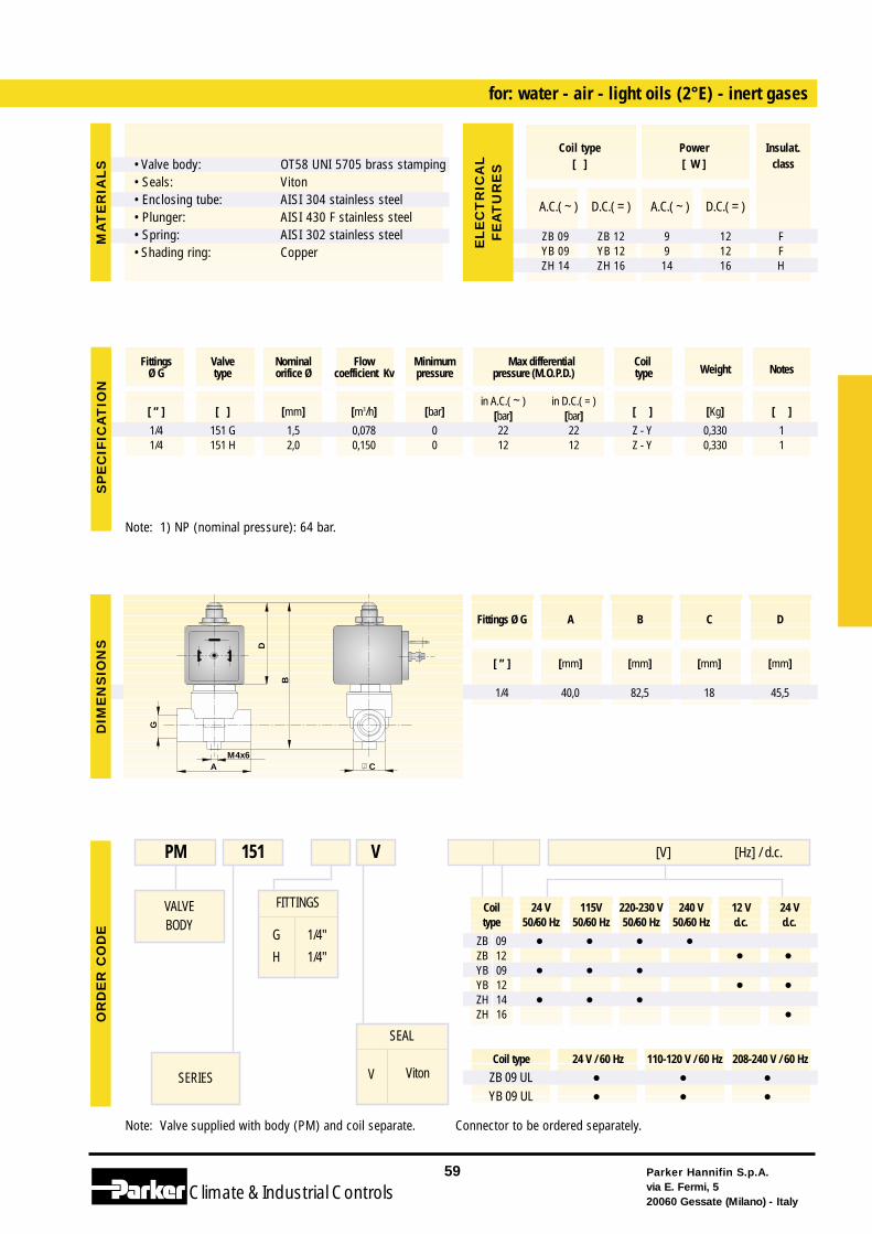
Coil 24 V 115V 220-230 V 240 V 12 V 24 Vtype 50/60 Hz 50/60 Hz 50/60 Hz 50/60 Hz d.c. d.c.
ZB 09 • • • •ZB 12 • •YB 09 • • •YB 12 • •ZH 14 • • •ZH 16 •
Coil type 24 V / 60 Hz 110-120 V / 60 Hz 208-240 V / 60 Hz
ZB 09 UL • • •YB 09 UL • • •
Note: Valve supplied with body (PM) and coil separate. Connector to be ordered separately.
FITTINGS
G
H
1/4"
1/4"
for: water - air - light oils (2°E) - inert gases
VALVEBODY
SERIES
PM 151 [V] [Hz] / d.c.V
SEAL
V Viton
Note: 1) NP (nominal pressure): 64 bar.
Parker Hannifin S.p.A.via E. Fermi, 520060 Gessate (Milano) - Italy
59
Climate& Industrial Controls
[ ” ] [ ] [mm] [m3/h] [bar]in A.C.( ~ ) in D.C.( = )
[ ] [Kg] [ ][bar] [bar]1/4 151 G 1,5 0,078 0 22 22 Z - Y 0,330 11/4 151 H 2,0 0,150 0 12 12 Z - Y 0,330 1
Fittings Valve Nominal Flow Minimum Max differential CoilWeight NotesØ G type orifice Ø coefficient Kv pressure pressure (M.O.P.D.) type
G
B
D
CAM4x6
SP
EC
IFIC
AT
ION
DIM
EN
SIO
NS
OR
DE
R C
OD
EM
AT
ER
IAL
S
A.C.( ~ ) D.C.( = ) A.C.( ~ ) D.C.( = )
ZB 09 ZB 12 9 12 FYB 09 YB 12 9 12 FZH 14 ZH 16 14 16 H
Coil type Power Insulat.[ ] [ W ] class
EL
EC
TR
ICA
LF
EA
TU
RE
S
Fittings Ø G A B C D
[ ” ] [mm] [mm] [mm] [mm]
1/4 40,0 82,5 18 45,5
• Valve body: • Seals:• Enclosing tube:• Plunger:• Spring:• Shading ring:
OT58 UNI 5705 brass stampingVitonAISI 304 stainless steelAISI 430 F stainless steelAISI 302 stainless steelCopper
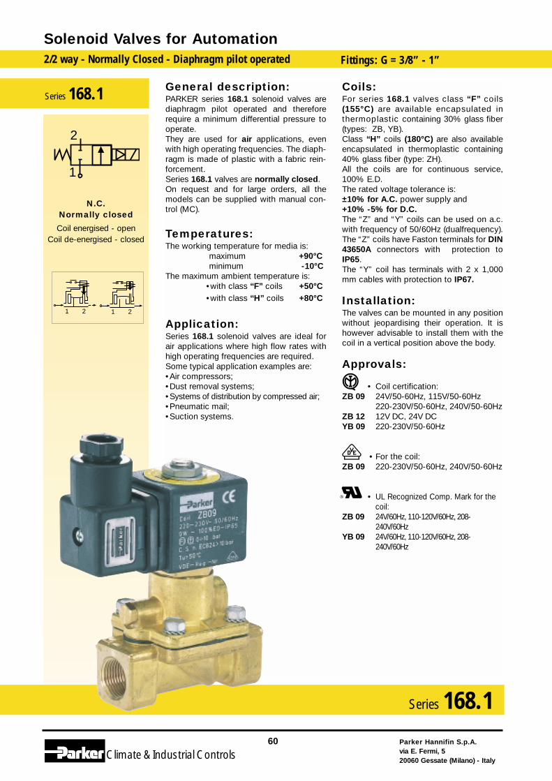
General description:PARKER series 168.1 solenoid valves arediaphragm pilot operated and thereforerequire a minimum differential pressure tooperate.They are used for air applications, evenwith high operating frequencies. The diaph-ragm is made of plastic with a fabric rein-forcement.Series 168.1 valves are normally closed.On request and for large orders, all themodels can be supplied with manual con-trol (MC).
Temperatures:The working temperature for media is:
maximum +90°Cminimum -10°C
The maximum ambient temperature is:•with class “F” coils +50°C•with class “H” coils +80°C
Application:Series 168.1 solenoid valves are ideal forair applications where high flow rates withhigh operating frequencies are required.Some typical application examples are:•Air compressors;•Dust removal systems;•Systems of distribution by compressed air;•Pneumatic mail;•Suction systems.
Coils:For series 168.1 valves class “F” coils(155°C) are available encapsulated inthermoplastic containing 30% glass fiber(types: ZB, YB).Class “H” coils (180°C) are also availableencapsulated in thermoplastic containing40% glass fiber (type: ZH).All the coils are for continuous service,100% E.D.The rated voltage tolerance is:±10% for A.C. power supply and+10% -5% for D.C.The “Z” and “Y” coils can be used on a.c.with frequency of 50/60Hz (dualfrequency).The “Z” coils have Faston terminals for DIN43650A connectors with protection toIP65.The “Y” coil has terminals with 2 x 1,000mm cables with protection to IP67.
Installation:The valves can be mounted in any positionwithout jeopardising their operation. It ishowever advisable to install them with thecoil in a vertical position above the body.
Approvals:
• Coil certification:ZB 09 24V/50-60Hz, 115V/50-60Hz
220-230V/50-60Hz, 240V/50-60HzZB 12 12V DC, 24V DC YB 09 220-230V/50-60Hz
• For the coil:ZB 09 220-230V/50-60Hz, 240V/50-60Hz
• UL Recognized Comp. Mark for thecoil:
ZB 09 24V/60Hz, 110-120V/60Hz, 208-240V/60Hz
YB 09 24V/60Hz, 110-120V/60Hz, 208-240V/60Hz
Solenoid Valves for Automation2/2 way - Normally Closed - Diaphragm pilot operated Fittings: G = 3/8” - 1”
Parker Hannifin S.p.A.via E. Fermi, 520060 Gessate (Milano) - Italy
60
Climate& Industrial Controls
Series 168.1
2121
2
1
N.C.Normally closed
Coil energised - openCoil de-energised - closed
Series 168.1
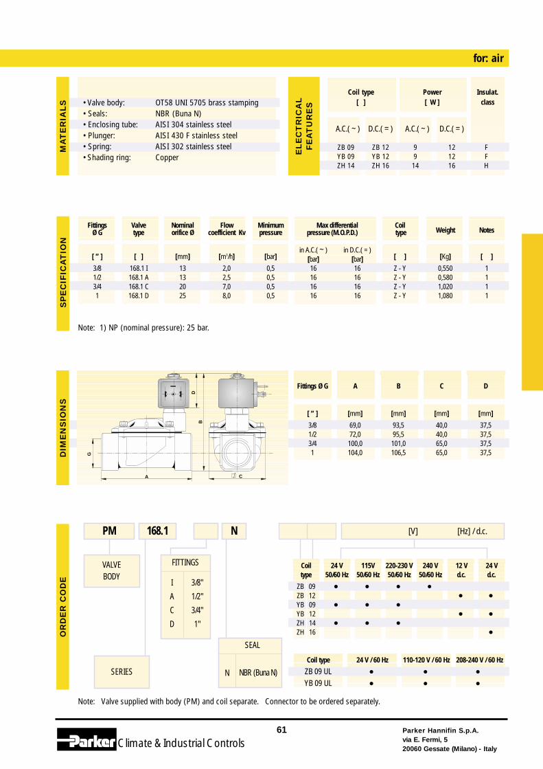
Coil 24 V 115V 220-230 V 240 V 12 V 24 Vtype 50/60 Hz 50/60 Hz 50/60 Hz 50/60 Hz d.c. d.c.
ZB 09 • • • •ZB 12 • •YB 09 • • •YB 12 • •ZH 14 • • •ZH 16 •
Coil type 24 V / 60 Hz 110-120 V / 60 Hz 208-240 V / 60 Hz
ZB 09 UL • • •YB 09 UL • • •
Note: Valve supplied with body (PM) and coil separate. Connector to be ordered separately.
FITTINGS
I
A
C
D
3/8"
1/2"
3/4"
1"
for: air
VALVEBODY
SERIES
PM 168.1 [V] [Hz] / d.c.N
Note: 1) NP (nominal pressure): 25 bar.
Parker Hannifin S.p.A.via E. Fermi, 520060 Gessate (Milano) - Italy
61
Climate& Industrial Controls
[ ” ] [ ] [mm] [m3/h] [bar]in A.C.( ~ ) in D.C.( = )
[ ] [Kg] [ ][bar] [bar]3/8 168.1 I 13 2,0 0,5 16 16 Z - Y 0,550 11/2 168.1 A 13 2,5 0,5 16 16 Z - Y 0,580 13/4 168.1 C 20 7,0 0,5 16 16 Z - Y 1,020 11 168.1 D 25 8,0 0,5 16 16 Z - Y 1,080 1
Fittings Valve Nominal Flow Minimum Max differential CoilWeight NotesØ G type orifice Ø coefficient Kv pressure pressure (M.O.P.D.) type
C
B
A
D
G
SP
EC
IFIC
AT
ION
DIM
EN
SIO
NS
OR
DE
R C
OD
EM
AT
ER
IAL
S
A.C.( ~ ) D.C.( = ) A.C.( ~ ) D.C.( = )
ZB 09 ZB 12 9 12 FYB 09 YB 12 9 12 FZH 14 ZH 16 14 16 H
Coil type Power Insulat.[ ] [ W ] class
EL
EC
TR
ICA
LF
EA
TU
RE
S
Fittings Ø G A B C D
[ ” ] [mm] [mm] [mm] [mm]
3/8 69,0 93,5 40,0 37,51/2 72,0 95,5 40,0 37,53/4 100,0 101,0 65,0 37,51 104,0 106,5 65,0 37,5
SEAL
N NBR (Buna N)
• Valve body: • Seals:• Enclosing tube:• Plunger:• Spring:• Shading ring:
OT58 UNI 5705 brass stampingNBR (Buna N)AISI 304 stainless steelAISI 430 F stainless steelAISI 302 stainless steelCopper
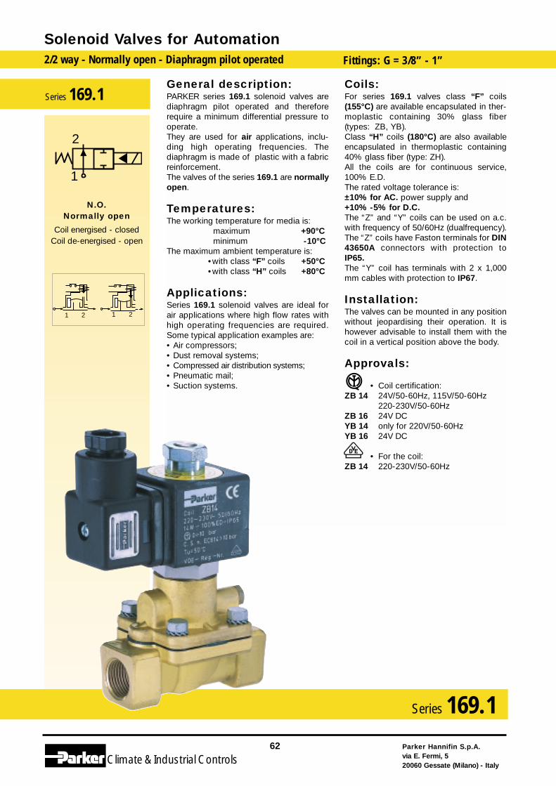
General description:PARKER series 169.1 solenoid valves arediaphragm pilot operated and thereforerequire a minimum differential pressure tooperate.They are used for air applications, inclu-ding high operating frequencies. Thediaphragm is made of plastic with a fabricreinforcement.The valves of the series 169.1 are normallyopen.
Temperatures:The working temperature for media is:
maximum +90°Cminimum -10°C
The maximum ambient temperature is:•with class “F” coils +50°C•with class “H” coils +80°C
Applications:Series 169.1 solenoid valves are ideal forair applications where high flow rates withhigh operating frequencies are required.Some typical application examples are:• Air compressors;• Dust removal systems;• Compressed air distribution systems;• Pneumatic mail;• Suction systems.
Coils:For series 169.1 valves class “F” coils(155°C) are available encapsulated in ther-moplastic containing 30% glass fiber(types: ZB, YB).Class “H” coils (180°C) are also availableencapsulated in thermoplastic containing40% glass fiber (type: ZH).All the coils are for continuous service,100% E.D.The rated voltage tolerance is:±10% for AC. power supply and+10% -5% for D.C.The “Z” and “Y” coils can be used on a.c.with frequency of 50/60Hz (dualfrequency).The “Z” coils have Faston terminals for DIN43650A connectors with protection toIP65.The “Y” coil has terminals with 2 x 1,000mm cables with protection to IP67.
Installation:The valves can be mounted in any positionwithout jeopardising their operation. It ishowever advisable to install them with thecoil in a vertical position above the body.
Approvals:
• Coil certification:ZB 14 24V/50-60Hz, 115V/50-60Hz
220-230V/50-60HzZB 16 24V DC YB 14 only for 220V/50-60HzYB 16 24V DC
• For the coil:ZB 14 220-230V/50-60Hz
Solenoid Valves for Automation2/2 way - Normally open - Diaphragm pilot operated Fittings: G = 3/8” - 1”
Parker Hannifin S.p.A.via E. Fermi, 520060 Gessate (Milano) - Italy
62
Climate& Industrial Controls
Series 169.1
2121
2
1
N.O.Normally open
Coil energised - closedCoil de-energised - open
Series 169.1
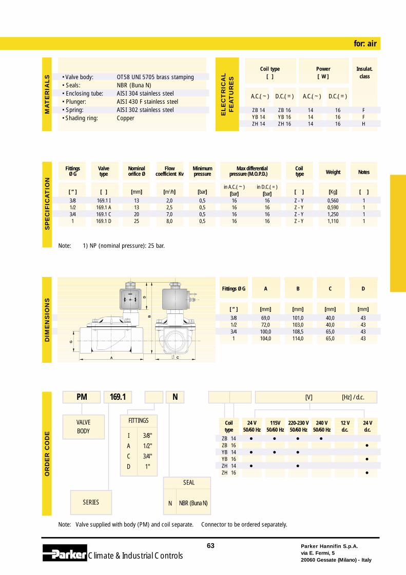
Coil 24 V 115V 220-230 V 240 V 12 V 24 Vtype 50/60 Hz 50/60 Hz 50/60 Hz 50/60 Hz d.c. d.c.
ZB 14 • • • •ZB 16 •YB 14 • • •YB 16 •ZH 14 • •ZH 16 •
Note: Valve supplied with body (PM) and coil separate. Connector to be ordered separately.
FITTINGS
I
A
C
D
3/8"
1/2"
3/4"
1"
for: air
VALVEBODY
SERIES
PM 169.1 [V] [Hz] / d.c.N
Note: 1) NP (nominal pressure): 25 bar.
Parker Hannifin S.p.A.via E. Fermi, 520060 Gessate (Milano) - Italy
63
Climate& Industrial Controls
[ ” ] [ ] [mm] [m3/h] [bar]in A.C.( ~ ) in D.C.( = )
[ ] [Kg] [ ][bar] [bar]3/8 169.1 I 13 2,0 0,5 16 16 Z - Y 0,560 11/2 169.1 A 13 2,5 0,5 16 16 Z - Y 0,590 13/4 169.1 C 20 7,0 0,5 16 16 Z - Y 1,250 11 169.1 D 25 8,0 0,5 16 16 Z - Y 1,110 1
Fittings Valve Nominal Flow Minimum Max differential CoilWeight NotesØ G type orifice Ø coefficient Kv pressure pressure (M.O.P.D.) type
C
B
A
D
G
SP
EC
IFIC
AT
ION
DIM
EN
SIO
NS
OR
DE
R C
OD
EM
AT
ER
IAL
S
A.C.( ~ ) D.C.( = ) A.C.( ~ ) D.C.( = )
ZB 14 ZB 16 14 16 FYB 14 YB 16 14 16 FZH 14 ZH 16 14 16 H
Coil type Power Insulat.[ ] [ W ] class
EL
EC
TR
ICA
LF
EA
TU
RE
S
Fittings Ø G A B C D
[ ” ] [mm] [mm] [mm] [mm]
3/8 69,0 101,0 40,0 431/2 72,0 103,0 40,0 433/4 100,0 108,5 65,0 431 104,0 114,0 65,0 43
SEAL
N NBR (Buna N)
• Valve body: • Seals:• Enclosing tube:• Plunger:• Spring:• Shading ring:
OT58 UNI 5705 brass stampingNBR (Buna N)AISI 304 stainless steelAISI 430 F stainless steelAISI 302 stainless steelCopper
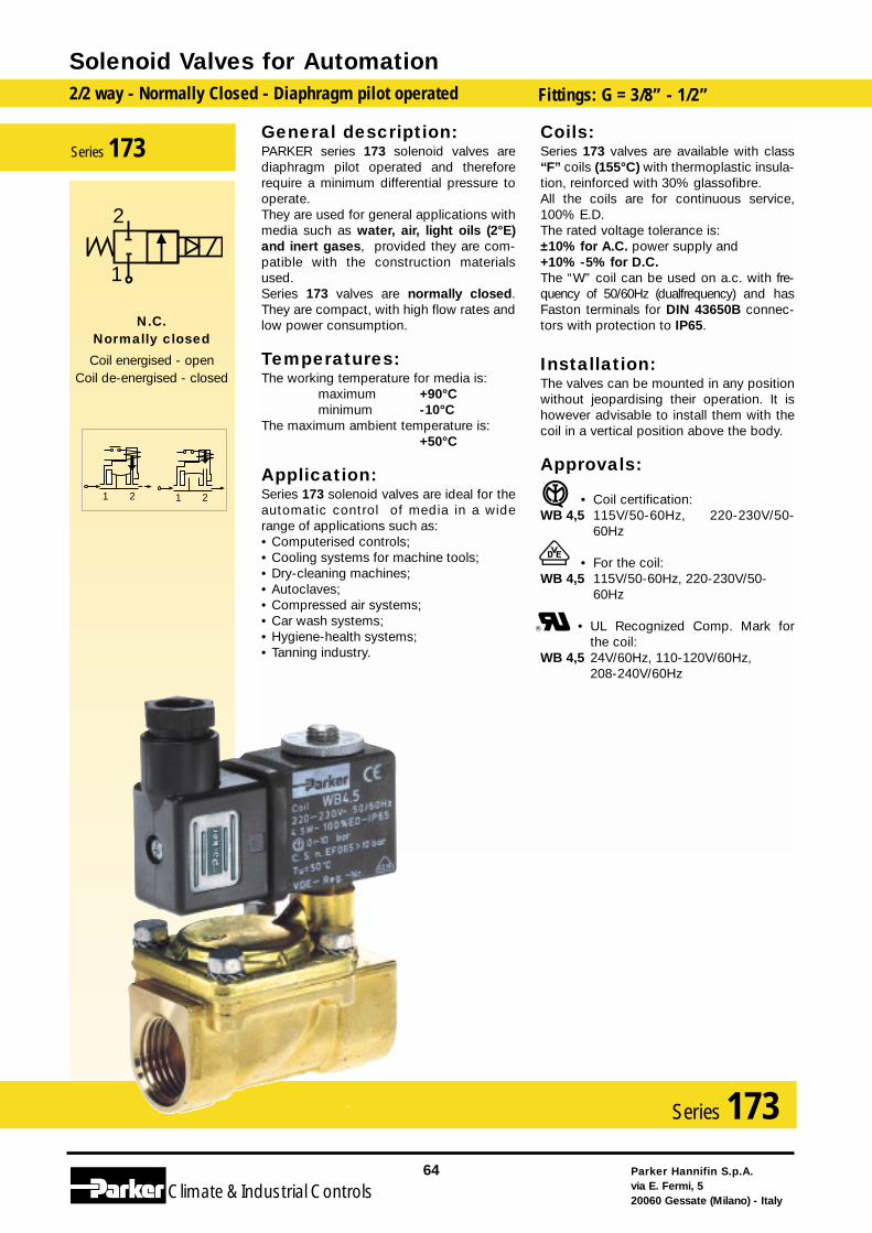
General description:PARKER series 173 solenoid valves arediaphragm pilot operated and thereforerequire a minimum differential pressure tooperate.They are used for general applications withmedia such as water, air, light oils (2°E)and inert gases, provided they are com-patible with the construction materialsused.Series 173 valves are normally closed.They are compact, with high flow rates andlow power consumption.
Temperatures:The working temperature for media is:
maximum +90°Cminimum -10°C
The maximum ambient temperature is: +50°C
Application:Series 173 solenoid valves are ideal for theautomatic control of media in a widerange of applications such as:• Computerised controls;• Cooling systems for machine tools;• Dry-cleaning machines;• Autoclaves;• Compressed air systems;• Car wash systems;• Hygiene-health systems;• Tanning industry.
Coils:Series 173 valves are available with class“F” coils (155°C) with thermoplastic insula-tion, reinforced with 30% glassofibre.All the coils are for continuous service,100% E.D.The rated voltage tolerance is:±10% for A.C. power supply and+10% -5% for D.C.The “W” coil can be used on a.c. with fre-quency of 50/60Hz (dualfrequency) and hasFaston terminals for DIN 43650B connec-tors with protection to IP65.
Installation:The valves can be mounted in any positionwithout jeopardising their operation. It ishowever advisable to install them with thecoil in a vertical position above the body.
Approvals:
• Coil certification:WB 4,5 115V/50-60Hz, 220-230V/50-
60Hz
• For the coil:WB 4,5 115V/50-60Hz, 220-230V/50-
60Hz
• UL Recognized Comp. Mark forthe coil:
WB 4,5 24V/60Hz, 110-120V/60Hz, 208-240V/60Hz
Solenoid Valves for Automation2/2 way - Normally Closed - Diaphragm pilot operated Fittings: G = 3/8” - 1/2”
Parker Hannifin S.p.A.via E. Fermi, 520060 Gessate (Milano) - Italy
64
Climate& Industrial Controls
Series 173
2121
2
1
N.C.Normally closed
Coil energised - openCoil de-energised - closed
Series 173
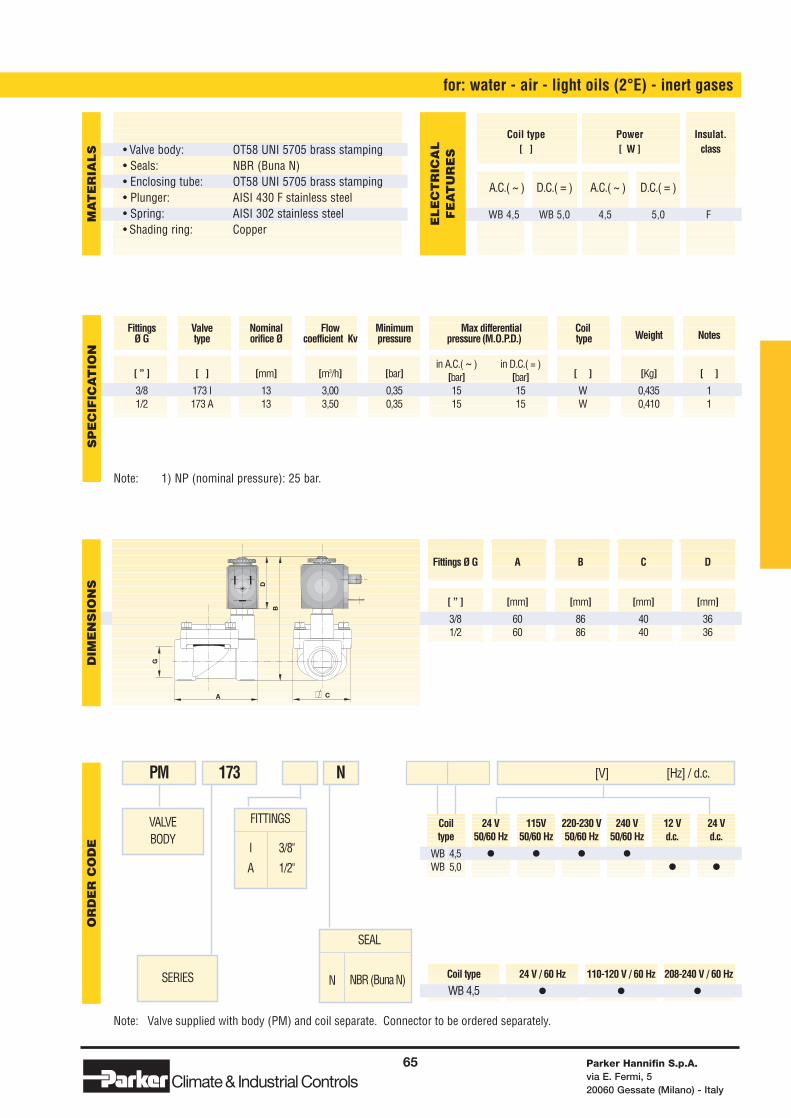
Coil 24 V 115V 220-230 V 240 V 12 V 24 Vtype 50/60 Hz 50/60 Hz 50/60 Hz 50/60 Hz d.c. d.c.
WB 4,5 • • • •WB 5,0 • •
Coil type 24 V / 60 Hz 110-120 V / 60 Hz 208-240 V / 60 Hz
WB 4,5 • • •
Note: Valve supplied with body (PM) and coil separate. Connector to be ordered separately.
FITTINGS
I
A
3/8"
1/2"
for: water - air - light oils (2°E) - inert gases
VALVEBODY
SERIES
PM 173 [V] [Hz] / d.c.N
Note: 1) NP (nominal pressure): 25 bar.
Parker Hannifin S.p.A.via E. Fermi, 520060 Gessate (Milano) - Italy
65
Climate& Industrial Controls
[ ” ] [ ] [mm] [m3/h] [bar]in A.C.( ~ ) in D.C.( = )
[ ] [Kg] [ ][bar] [bar]3/8 173 I 13 3,00 0,35 15 15 W 0,435 11/2 173 A 13 3,50 0,35 15 15 W 0,410 1
Fittings Valve Nominal Flow Minimum Max differential CoilWeight NotesØ G type orifice Ø coefficient Kv pressure pressure (M.O.P.D.) type
B
A
G
C
D
SP
EC
IFIC
AT
ION
DIM
EN
SIO
NS
OR
DE
R C
OD
EM
AT
ER
IAL
S
A.C.( ~ ) D.C.( = ) A.C.( ~ ) D.C.( = )
WB 4,5 WB 5,0 4,5 5,0 F
Coil type Power Insulat.[ ] [ W ] class
EL
EC
TR
ICA
LF
EA
TU
RE
S
Fittings Ø G A B C D
[ ” ] [mm] [mm] [mm] [mm]
3/8 60 86 40 361/2 60 86 40 36
SEAL
N NBR (Buna N)
• Valve body: • Seals:• Enclosing tube:• Plunger:• Spring:• Shading ring:
OT58 UNI 5705 brass stampingNBR (Buna N) OT58 UNI 5705 brass stampingAISI 430 F stainless steelAISI 302 stainless steelCopper
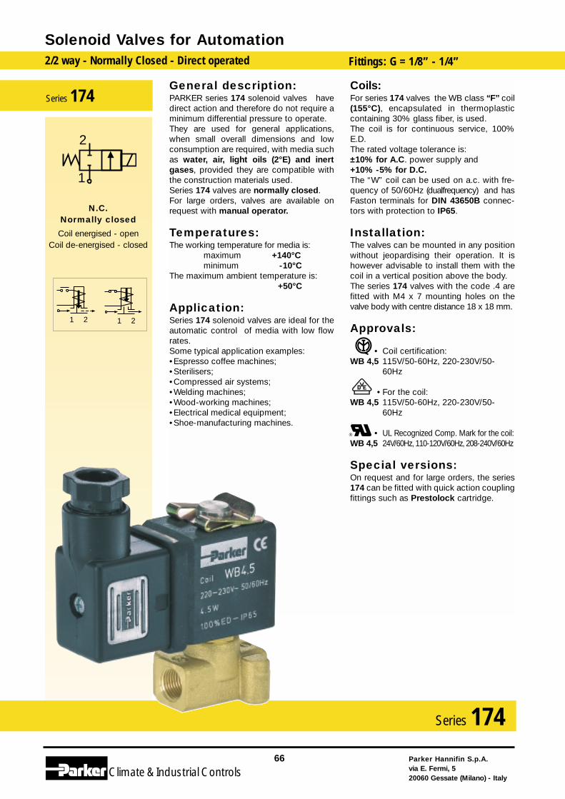
General description:PARKER series 174 solenoid valves havedirect action and therefore do not require aminimum differential pressure to operate.They are used for general applications,when small overall dimensions and lowconsumption are required, with media suchas water, air, light oils (2°E) and inertgases, provided they are compatible withthe construction materials used.Series 174 valves are normally closed.For large orders, valves are available onrequest with manual operator.
Temperatures:The working temperature for media is:
maximum +140°Cminimum -10°C
The maximum ambient temperature is:+50°C
Application:Series 174 solenoid valves are ideal for theautomatic control of media with low flowrates.Some typical application examples:•Espresso coffee machines;•Sterilisers;•Compressed air systems;•Welding machines;•Wood-working machines;•Electrical medical equipment;•Shoe-manufacturing machines.
Coils:For series 174 valves the WB class “F” coil(155°C), encapsulated in thermoplasticcontaining 30% glass fiber, is used.The coil is for continuous service, 100%E.D.The rated voltage tolerance is:±10% for A.C. power supply and+10% -5% for D.C.The “W” coil can be used on a.c. with fre-quency of 50/60Hz (dualfrequency) and hasFaston terminals for DIN 43650B connec-tors with protection to IP65.
Installation:The valves can be mounted in any positionwithout jeopardising their operation. It ishowever advisable to install them with thecoil in a vertical position above the body.The series 174 valves with the code .4 arefitted with M4 x 7 mounting holes on thevalve body with centre distance 18 x 18 mm.
Approvals:
• Coil certification:WB 4,5 115V/50-60Hz, 220-230V/50-
60Hz
• For the coil:WB 4,5 115V/50-60Hz, 220-230V/50-
60Hz
• UL Recognized Comp. Mark for the coil:WB 4,5 24V/60Hz, 110-120V/60Hz, 208-240V/60Hz
Special versions:On request and for large orders, the series174 can be fitted with quick action couplingfittings such as Prestolock cartridge.
Solenoid Valves for Automation2/2 way - Normally Closed - Direct operated Fittings: G = 1/8” - 1/4”
Parker Hannifin S.p.A.via E. Fermi, 520060 Gessate (Milano) - Italy
66
Climate& Industrial Controls
Series 174
2121
2
1
N.C.Normally closed
Coil energised - openCoil de-energised - closed
Series 174
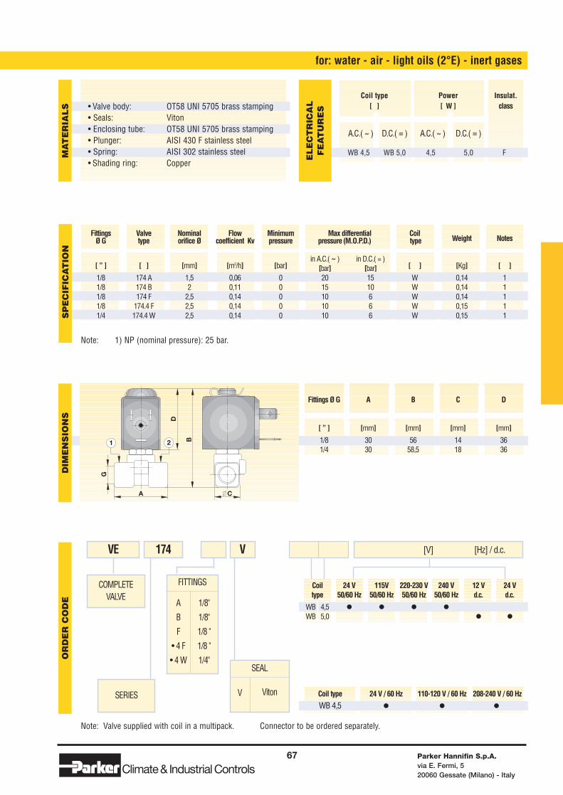
Coil 24 V 115V 220-230 V 240 V 12 V 24 Vtype 50/60 Hz 50/60 Hz 50/60 Hz 50/60 Hz d.c. d.c.
WB 4,5 • • • •WB 5,0 • •
Coil type 24 V / 60 Hz 110-120 V / 60 Hz 208-240 V / 60 Hz
WB 4,5 • • •Note: Valve supplied with coil in a multipack. Connector to be ordered separately.
FITTINGS
A
B
F
• 4 F
• 4 W
1/8"
1/8"
1/8 "
1/8 "
1/4"
for: water - air - light oils (2°E) - inert gases
COMPLETEVALVE
SERIES
VE 174 [V] [Hz] / d.c.V
SEAL
V Viton
Note: 1) NP (nominal pressure): 25 bar.
Parker Hannifin S.p.A.via E. Fermi, 520060 Gessate (Milano) - Italy
67
Climate& Industrial Controls
[ ” ] [ ] [mm] [m3/h] [bar]in A.C.( ~ ) in D.C.( = )
[ ] [Kg] [ ][bar] [bar]1/8 174 A 1,5 0,06 0 20 15 W 0,14 1 1/8 174 B 2 0,11 0 15 10 W 0,14 1 1/8 174 F 2,5 0,14 0 10 6 W 0,14 11/8 174.4 F 2,5 0,14 0 10 6 W 0,15 1 1/4 174.4 W 2,5 0,14 0 10 6 W 0,15 1
Fittings Valve Nominal Flow Minimum Max differential CoilWeight NotesØ G type orifice Ø coefficient Kv pressure pressure (M.O.P.D.) type
D
B
A C
G
1 2
SP
EC
IFIC
AT
ION
DIM
EN
SIO
NS
OR
DE
R C
OD
EM
AT
ER
IAL
S
A.C.( ~ ) D.C.( = ) A.C.( ~ ) D.C.( = )
WB 4,5 WB 5,0 4,5 5,0 F
Coil type Power Insulat.[ ] [ W ] class
EL
EC
TR
ICA
LF
EA
TU
RE
S
Fittings Ø G A B C D
[ ” ] [mm] [mm] [mm] [mm]
1/8 30 56 14 361/4 30 58,5 18 36
• Valve body: • Seals:• Enclosing tube:• Plunger:• Spring:• Shading ring:
OT58 UNI 5705 brass stampingVitonOT58 UNI 5705 brass stampingAISI 430 F stainless steelAISI 302 stainless steelCopper
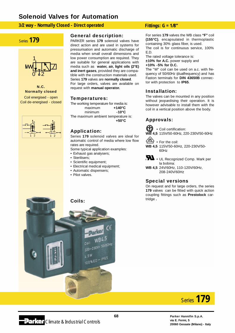
General description:PARKER series 179 solenoid valves havedirect action and are used in systems forpressurisation and automatic discharge ofmedia when small overall dimensions andlow power consumption are required. Theyare suitable for general applications withmedia such as water, air, light oils (2°E)and inert gases, provided they are compa-tible with the construction materials used.Series 179 valves are normally closed.For large orders, valves are available onrequest with manual operator.
Temperatures:The working temperature for media is:
maximum +140°Cminimum -10°C
The maximum ambient temperature is:+50°C
Application:Series 179 solenoid valves are ideal forautomatic control of media where low flowrates are required.Some typical application examples:• Exhaust gas analysers;• Sterilisers;• Scientific equipment;• Electrical medical equipment;• Automatic dispensers;• Pilot valves.
Coils:
For series 179 valves the WB class “F” coil(155°C), encapsulated in thermoplasticcontaining 30% glass fiber, is used.The coil is for continuous service, 100%E.D.The rated voltage tolerance is:±10% for A.C. power supply and+10% -5% for D.C.The “W” coil can be used on a.c. with fre-quency of 50/60Hz (dualfrequency) and hasFaston terminals for DIN 43650B connec-tor with protection to IP65.
Installation:The valves can be mounted in any positionwithout jeopardising their operation. It ishowever advisable to install them with thecoil in a vertical position above the body.
Approvals:
• Coil certification:WB 4,5 115V/50-60Hz, 220-230V/50-60Hz
• For the coil:WB 4,5 115V/50-60Hz, 220-230V/50-
60Hz
• UL Recognized Comp. Mark per la bobina:
WB 4,5 24V/60Hz, 110-120V/60Hz, 208-240V/60Hz
Special versionsOn request and for large orders, the series179 valves can be fitted with quick actioncoupling fittings such as Prestolock car-tridge .
Solenoid Valves for Automation3/2 way - Normally Closed - Direct operated Fittings: G = 1/8”
Parker Hannifin S.p.A.via E. Fermi, 520060 Gessate (Milano) - Italy
68
Climate& Industrial Controls
Series 179
21
0
21
0
2
1
0
N.C.Normally closed
Coil energised - openCoil de-energised - closed
Series 179
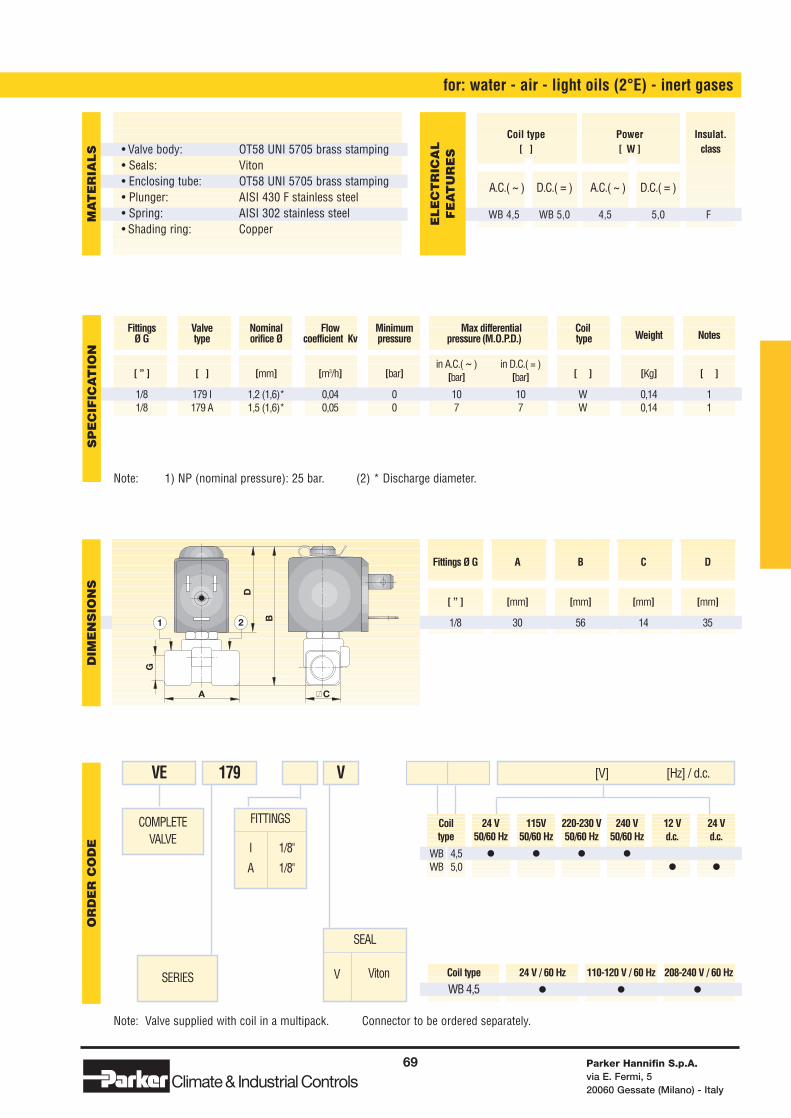
Coil 24 V 115V 220-230 V 240 V 12 V 24 Vtype 50/60 Hz 50/60 Hz 50/60 Hz 50/60 Hz d.c. d.c.
WB 4,5 • • • •WB 5,0 • •
Coil type 24 V / 60 Hz 110-120 V / 60 Hz 208-240 V / 60 Hz
WB 4,5 • • •
Note: Valve supplied with coil in a multipack. Connector to be ordered separately.
FITTINGS
I
A
1/8"
1/8"
for: water - air - light oils (2°E) - inert gases
COMPLETEVALVE
SERIES
VE 179 [V] [Hz] / d.c.V
SEAL
V Viton
Note: 1) NP (nominal pressure): 25 bar. (2) * Discharge diameter.
Parker Hannifin S.p.A.via E. Fermi, 520060 Gessate (Milano) - Italy
69
Climate& Industrial Controls
[ ” ] [ ] [mm] [m3/h] [bar]in A.C.( ~ ) in D.C.( = )
[ ] [Kg] [ ][bar] [bar]
1/8 179 I 1,2 (1,6)* 0,04 0 10 10 W 0,14 11/8 179 A 1,5 (1,6)* 0,05 0 7 7 W 0,14 1
Fittings Valve Nominal Flow Minimum Max differential CoilWeight NotesØ G type orifice Ø coefficient Kv pressure pressure (M.O.P.D.) type
D
B
A C
G
1 2
SP
EC
IFIC
AT
ION
DIM
EN
SIO
NS
OR
DE
R C
OD
EM
AT
ER
IAL
S
A.C.( ~ ) D.C.( = ) A.C.( ~ ) D.C.( = )
WB 4,5 WB 5,0 4,5 5,0 F
Coil type Power Insulat.[ ] [ W ] class
EL
EC
TR
ICA
LF
EA
TU
RE
S
Fittings Ø G A B C D
[ ” ] [mm] [mm] [mm] [mm]
1/8 30 56 14 35
• Valve body: • Seals:• Enclosing tube:• Plunger:• Spring:• Shading ring:
OT58 UNI 5705 brass stampingVitonOT58 UNI 5705 brass stampingAISI 430 F stainless steelAISI 302 stainless steelCopper
Solenoid Valves for Automation
Parker Hannifin S.p.A.via E. Fermi, 520060 Gessate (Milano) - Italy
70
Climate& Industrial ControlsClimate& Industrial Controls
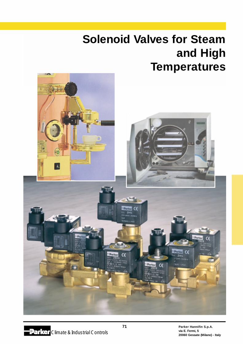
Parker Hannifin S.p.A.via E. Fermi, 520060 Gessate (Milano) - Italy
71
Climate& Industrial Controls
Solenoid Valves for Steam and High
Temperatures
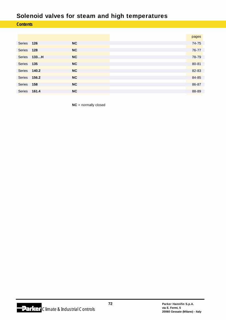
Solenoid valves for steam and high temperaturesContents
Parker Hannifin S.p.A.via E. Fermi, 520060 Gessate (Milano) - Italy
72
Climate& Industrial Controls
Series 126
Series 128
Series 133…H
Series 135
Series 140.2
Series 156.2
Series 158
Series 161.4
NC
NC
NC
NC
NC
NC
NC
NC
NC = normally closed
pages
74-75
76-77
78-79
80-81
82-83
84-85
86-87
88-89
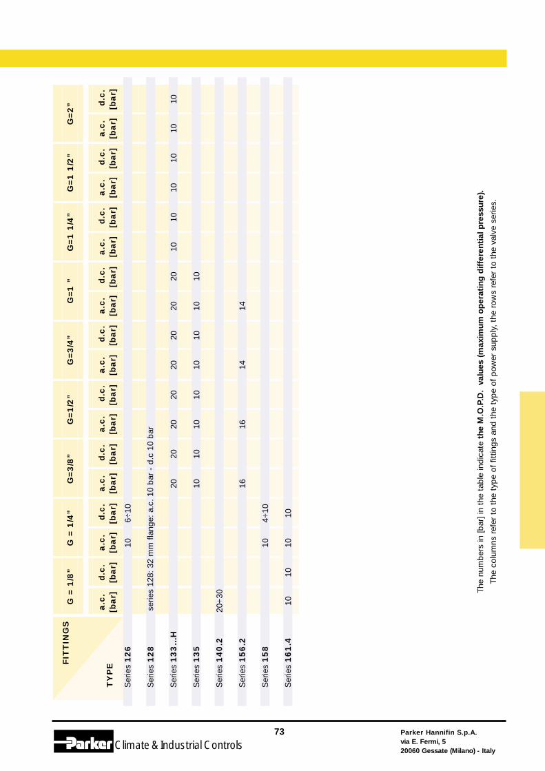
Parker Hannifin S.p.A.via E. Fermi, 520060 Gessate (Milano) - Italy
73
Climate& Industrial Controls
The
num
ber
s in
[bar
] in
the
tab
le in
dic
ate
the
M.O
.P.D
. va
lues
(m
axim
um o
per
atin
g d
iffer
enti
al p
ress
ure)
.
The
colu
mns
ref
er t
o th
e ty
pe
of f
ittin
gs a
nd t
he t
ype
of p
ower
sup
ply
, th
e ro
ws
refe
r to
the
val
ve s
erie
s.
a.c
.[b
ar]
d.c
.[b
ar]
a.c
.[b
ar]
d.c
.[b
ar]
a.c
.[b
ar]
d.c
.[b
ar]
a.c
.[b
ar]
d.c
.[b
ar]
a.c
.[b
ar]
d.c
.[b
ar]
a.c
.[b
ar]
d.c
.[b
ar]
a.c
.[b
ar]
d.c
.[b
ar]
a.c
.[b
ar]
d.c
.[b
ar]
a.c
.[b
ar]
d.c
.[b
ar]
G=3
/8”
G=1
/2”
G=3
/4”
G=1
”G
=1
1/4
”G
=1
1/2
”G
=2
”F
ITT
ING
S
TY
PE
G =
1/8
”G
= 1
/4”
Ser
ies
126
Ser
ies
128
Ser
ies
133…
H
Ser
ies
135
Ser
ies
140.2
Ser
ies
156.2
Ser
ies
158
Ser
ies
161.4
20 10 16
20 10
20 10 16
6÷10
4÷10 10
10 10 1010
20÷
30
10
serie
s 12
8: 3
2 m
m f
lang
e: a
.c.
10 b
ar -
d.c
10
bar
1010
1010
1010
20 10
20 10 14
20 10
20 10 14
20 10
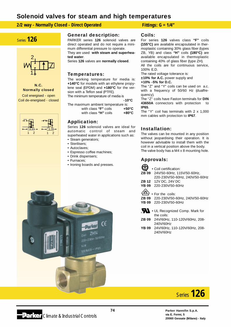
General description:PARKER series 126 solenoid valves aredirect operated and do not require a mini-mum differential pressure to operate. They are used with steam and superhea-ted water.Series 126 valves are normally closed.
Temperatures:The working temperature for media is:+140°C for models with an ethylene propy-lene seal (EPDM) and +180°C for the ver-sion with a Teflon seal (PTFE).The minimum temperature of media is
-10°CThe maximum ambient temperature is:
with class “F” coils +50°Cwith class “H” coils +80°C
Application:Series 126 solenoid valves are ideal forautomatic control of steam andsuperheated water in applications such as:• Steam generators;• Sterilisers;• Autoclaves;• Espresso coffee machines;• Drink dispensers;• Furnaces;• Ironing boards and presses.
Coils:For series 126 valves class “F” coils(155°C) are available encapsulated in ther-moplastic containing 30% glass fiber (typesZB, YB) and class “H” coils (180°C) areavailable encapsulated in thermoplasticcontaining 40% of glass fiber (type ZH).All the coils are for continuous service,100% E.D.The rated voltage tolerance is:±10% for A.C. power supply and+10% -5% for D.C.The “Z” and “Y” coils can be used on a.c.with a frequency of 50/60 Hz (dualfre-quency).The “Z” coils have Faston terminals for DIN43650A connectors with protection toIP65.The “Y” coil has terminals with 2 x 1,000mm cables with protection to IP67.
Installation:The valves can be mounted in any positionwithout jeopardising their operation. It ishowever advisable to install them with thecoil in a vertical position above the body.The valve body has a M4 x 8 mounting hole.
Approvals:
• Coil certification:ZB 09 24V/50-60Hz, 115V/50-60Hz,
220-230V/50-60Hz, 240V/50-60HzZB 12 12V DC, 24V DCYB 09 220-230V/50-60Hz
• For the coils:ZB 09 220-230V/50-60Hz, 240V/50-60HzYB 09 220-230V/50-60Hz
•UL Recognized Comp. Mark forthe coils:
ZB 09 24V/60Hz, 110-120V/60Hz, 208-240V/60Hz
YB 09 24V/60Hz, 110-120V/60Hz, 208-240V/60Hz
Solenoid valves for steam and high temperatures2/2 way - Normally Closed - Direct Operated Fittings: G = 1/4”
Parker Hannifin S.p.A.via E. Fermi, 520060 Gessate (Milano) - Italy
74
Climate& Industrial Controls
Series 126
2121
2
1
N.C.Normally closed
Coil energised - openCoil de-energised - closed
Series 126
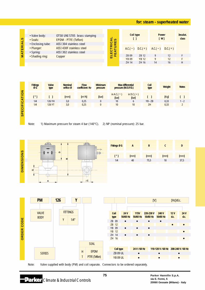
SEAL
H
T
EPDM
PTFE (Teflon)
Coil 24 V 115V 220-230 V 240 V 12 V 24 Vtype 50/60 Hz 50/60 Hz 50/60 Hz 50/60 Hz d.c. d.c.
ZB 09 • • • •ZB 12 • •YB 09 • • •YB 12 •ZH 14 • • •ZH 16 •
Coil type 24 V / 60 Hz 110-120 V / 60 Hz 208-240 V / 60 Hz
ZB 09 UL • • •YB 09 UL • • •
Note: Valve supplied with body (PM) and coil separate. Connectors to be ordered separately.
FITTINGS
Y 1/4"
for: steam - superheated water
VALVEBODY
SERIES
PM 126 Y [V] [Hz]/d.c.
Note: 1) Maximum pressure for steam 4 bar (140°C). 2) NP (nominal pressure): 25 bar.
Parker Hannifin S.p.A.via E. Fermi, 520060 Gessate (Milano) - Italy
75
Climate& Industrial Controls
[ ” ] [ ] [mm] [m3/h] [bar]in A.C.( ~ ) in D.C.( = )
[ ] [Kg] [ ][bar] [bar]1/4 126 YH 3,0 0,25 0 10 6 YB - ZB 0,33 1 - 21/4 126 YT 3,0 0,25 0 10 10 ZH 0,33 2
Fittings Valve Nominal Flow Minimum Max differential CoilWeight NotesØ G type orifice Ø coefficient Kv pressure pressure (M.O.P.D.) type
G
B
A C
D
SP
EC
IFIC
AT
ION
DIM
EN
SIO
NS
OR
DE
RC
OD
EM
AT
ER
IAL
S
A.C.( ~ ) D.C.( = ) A.C.( ~ ) D.C.( = )
ZB 09 ZB 12 9 12 FYB 09 YB 12 9 12 FZH 14 ZH 16 14 16 H
Coil type Power Insulat.[ ] [ W ] class
EL
EC
TR
ICA
LF
EA
TU
RE
S
Fittings Ø G A B C D
[ ” ] [mm] [mm] [mm] [mm]
1/4 40 75,5 18 37,5
• Valve body:• Seals:• Enclosing tube:• Plunger:• Spring:• Shading ring:
OT58 UNI 5705 brass stampingEPDM - PTFE (Teflon)AISI 304 stainless steelAISI 430F stainless steelAISI 302 stainless steelCopper
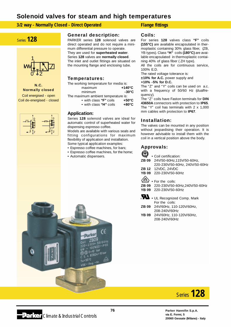
General description:PARKER series 128 solenoid valves aredirect operated and do not require a mini-mum differential pressure to operate. They are used for superheated water.Series 128 valves are normally closed.The inlet and outlet fittings are situated onthe mounting flange and enclosing tube.
Temperatures:The working temperature for media is:
maximum +140°Cminimum -30°C
The maximum ambient temperature is:• with class “F” coils +50°C• with class “H” coils +80°C
Application:Series 128 solenoid valves are ideal forautomatic control of superheated water fordispensing espresso coffee.Models are available with various seals andfitt ing configurations for maximumflexibility of application and installation.Some typical application examples:• Espresso coffee machines, for bars;• Espresso coffee machines, for the home;• Automatic dispensers.
Coils:For series 128 valves class “F” coils(155°C) are available encapsulated in ther-moplastic containing 30% glass fiber, (ZB,YB types). Class “H” coils (180°C) are avai-lable encapsulated in thermoplastic contai-ning 40% of glass fiber ( ZH type).All the coils are for continuous service,100% E.D.The rated voltage tolerance is:±10% for A.C. power supply and+10% -5% for D.C.The “Z” and “Y” coils can be used on a.c.with a frequency of 50/60 Hz (dualfre-quency).The “Z” coils have Faston terminals for DIN43650A connectors with protection to IP65.The “Y” coil has terminals with 2 x 1,000mm cables with protection to IP67.
Installation:The valves can be mounted in any positionwithout jeopardising their operation. It ishowever advisable to install them with thecoil in a vertical position above the body.
Approvals:
• Coil certification:ZB 09 24V/50-60Hz,115V/50-60Hz,
220-230V/50-60Hz, 240V/50-60HzZB 12 12VDC, 24VDC YB 09 220-230V/50-60Hz
• For the coils:ZB 09 220-230V/50-60Hz,240V/50-60HzYB 09 220-230V/50-60Hz
• UL Recognized Comp. MarkFor the coils:
ZB 09 24V/60Hz, 110-120V/60Hz,208-240V/60Hz
YB 09 24V/60Hz, 110-120V/60Hz,208-240V/60Hz
Solenoid valves for steam and high temperatures3/2 way - Normally Closed - Direct Operated Flange fittings
Parker Hannifin S.p.A.via E. Fermi, 520060 Gessate (Milano) - Italy
76
Climate& Industrial Controls
Series 128
1 2
0
1 2
0
2
1
0
N.C.Normally closed
Coil energised - openCoil de-energised - closed
Series 128
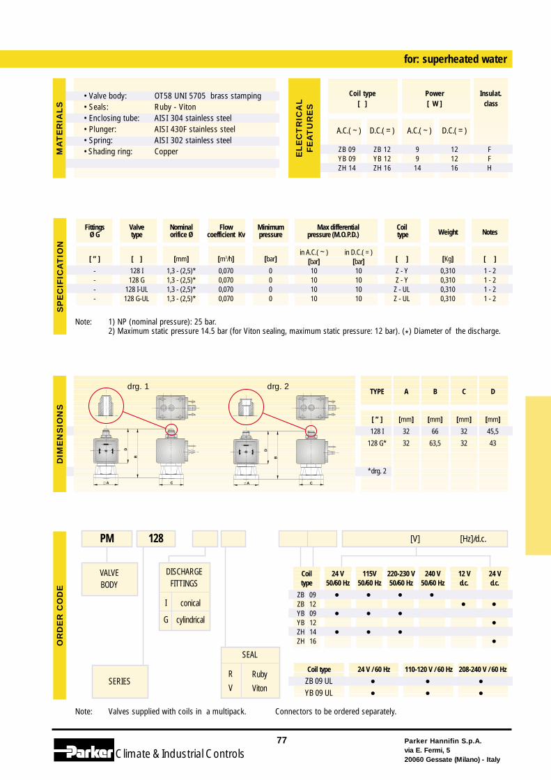
Coil 24 V 115V 220-230 V 240 V 12 V 24 Vtype 50/60 Hz 50/60 Hz 50/60 Hz 50/60 Hz d.c. d.c.
ZB 09 • • • •ZB 12 • •YB 09 • • •YB 12 •ZH 14 • • •ZH 16 •
Coil type 24 V / 60 Hz 110-120 V / 60 Hz 208-240 V / 60 Hz
ZB 09 UL • • •YB 09 UL • • •
Note: Valves supplied with coils in a multipack. Connectors to be ordered separately.
DISCHARGEFITTINGS
I
G
conical
cylindrical
for: superheated water
VALVEBODY
SERIES
PM 128 [V] [Hz]/d.c.
SEAL
R
VRuby
Viton
Note: 1) NP (nominal pressure): 25 bar.2) Maximum static pressure 14.5 bar (for Viton sealing, maximum static pressure: 12 bar). (*) Diameter of the discharge.
Parker Hannifin S.p.A.via E. Fermi, 520060 Gessate (Milano) - Italy
77
Climate& Industrial Controls
[ ” ] [ ] [mm] [m3/h] [bar]in A.C.( ~ ) in D.C.( = )
[ ] [Kg] [ ][bar] [bar]- 128 I 1,3 - (2,5)* 0,070 0 10 10 Z - Y 0,310 1 - 2- 128 G 1,3 - (2,5)* 0,070 0 10 10 Z - Y 0,310 1 - 2- 128 I-UL 1,3 - (2,5)* 0,070 0 10 10 Z - UL 0,310 1 - 2- 128 G-UL 1,3 - (2,5)* 0,070 0 10 10 Z - UL 0,310 1 - 2
Fittings Valve Nominal Flow Minimum Max differential CoilWeight NotesØ G type orifice Ø coefficient Kv pressure pressure (M.O.P.D.) type
B
D
A C
SP
EC
IFIC
AT
ION
DIM
EN
SIO
NS
OR
DE
RC
OD
E
A.C.( ~ ) D.C.( = ) A.C.( ~ ) D.C.( = )
ZB 09 ZB 12 9 12 FYB 09 YB 12 9 12 FZH 14 ZH 16 14 16 H
Coil type Power Insulat.[ ] [ W ] class
EL
EC
TR
ICA
LF
EA
TU
RE
S
TYPE A B C D
[ ” ] [mm] [mm] [mm] [mm]
128 I 32 66 32 45,5
128 G* 32 63,5 32 43
*drg. 2
MA
TE
RIA
LS
C
B
D
A
drg. 1 drg. 2
• Valve body:• Seals:• Enclosing tube:• Plunger:• Spring:• Shading ring:
OT58 UNI 5705 brass stampingRuby - VitonAISI 304 stainless steelAISI 430F stainless steelAISI 302 stainless steelCopper
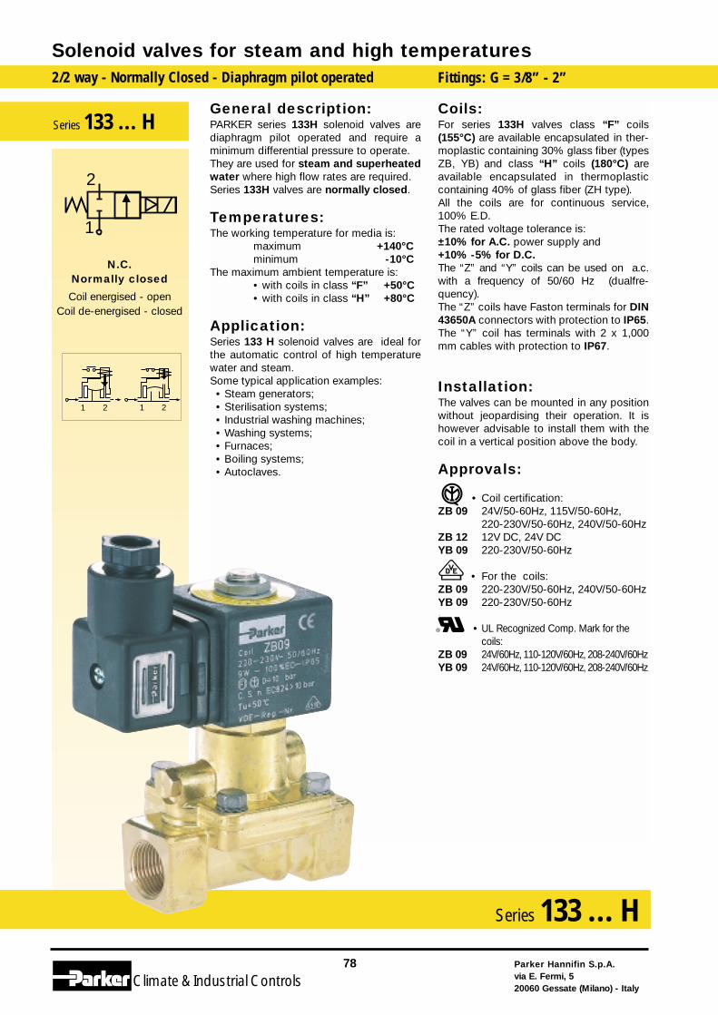
General description:PARKER series 133H solenoid valves arediaphragm pilot operated and require aminimum differential pressure to operate. They are used for steam and superheatedwater where high flow rates are required.Series 133H valves are normally closed.
Temperatures:The working temperature for media is:
maximum +140°Cminimum -10°C
The maximum ambient temperature is:• with coils in class “F” +50°C• with coils in class “H” +80°C
Application:Series 133 H solenoid valves are ideal forthe automatic control of high temperaturewater and steam.Some typical application examples:• Steam generators;• Sterilisation systems;• Industrial washing machines;• Washing systems;• Furnaces;• Boiling systems;• Autoclaves.
Coils:For series 133H valves class “F” coils(155°C) are available encapsulated in ther-moplastic containing 30% glass fiber (typesZB, YB) and class “H” coils (180°C) areavailable encapsulated in thermoplasticcontaining 40% of glass fiber (ZH type).All the coils are for continuous service,100% E.D.The rated voltage tolerance is:±10% for A.C. power supply and+10% -5% for D.C.The “Z” and “Y” coils can be used on a.c.with a frequency of 50/60 Hz (dualfre-quency).The “Z” coils have Faston terminals for DIN43650A connectors with protection to IP65.The “Y” coil has terminals with 2 x 1,000mm cables with protection to IP67.
Installation:The valves can be mounted in any positionwithout jeopardising their operation. It ishowever advisable to install them with thecoil in a vertical position above the body.
Approvals:
• Coil certification:ZB 09 24V/50-60Hz, 115V/50-60Hz,
220-230V/50-60Hz, 240V/50-60HzZB 12 12V DC, 24V DCYB 09 220-230V/50-60Hz
• For the coils:ZB 09 220-230V/50-60Hz, 240V/50-60HzYB 09 220-230V/50-60Hz
• UL Recognized Comp. Mark for thecoils:
ZB 09 24V/60Hz, 110-120V/60Hz, 208-240V/60HzYB 09 24V/60Hz, 110-120V/60Hz, 208-240V/60Hz
Solenoid valves for steam and high temperatures2/2 way - Normally Closed - Diaphragm pilot operated Fittings: G = 3/8” - 2”
Parker Hannifin S.p.A.via E. Fermi, 520060 Gessate (Milano) - Italy
78
Climate& Industrial Controls
Series 133 ... H
2121
2
1
N.C.Normally closed
Coil energised - openCoil de-energised - closed
Series 133 ... H
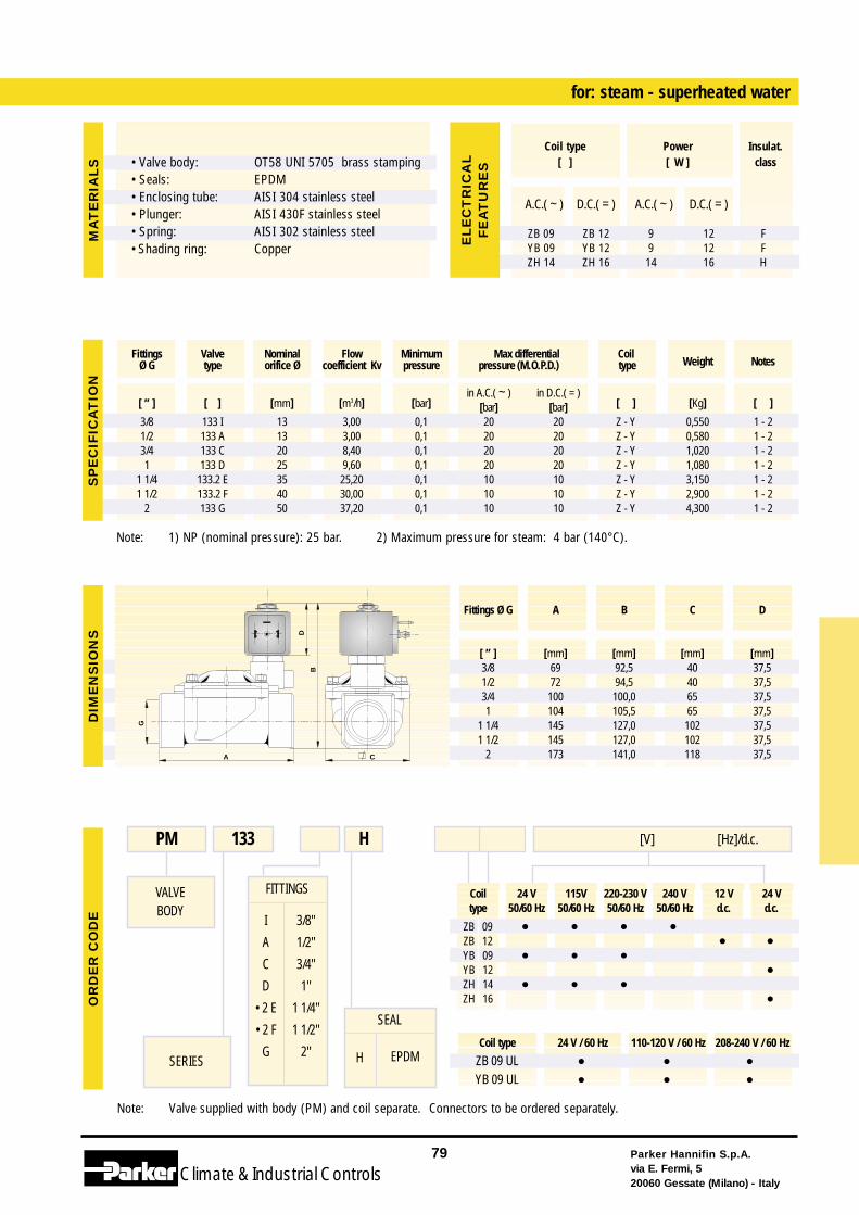
Coil 24 V 115V 220-230 V 240 V 12 V 24 Vtype 50/60 Hz 50/60 Hz 50/60 Hz 50/60 Hz d.c. d.c.
ZB 09 • • • •ZB 12 • •YB 09 • • •YB 12 •ZH 14 • • •ZH 16 •
Coil type 24 V / 60 Hz 110-120 V / 60 Hz 208-240 V / 60 Hz
ZB 09 UL • • •YB 09 UL • • •
Note: Valve supplied with body (PM) and coil separate. Connectors to be ordered separately.
FITTINGS
I
A
C
D
• 2 E
• 2 F
G
3/8"
1/2"
3/4"
1"
1 1/4"
1 1/2"
2"
for: steam - superheated water
VALVEBODY
SERIES
PM 133 [V] [Hz]/d.c.H
SEAL
H EPDM
Parker Hannifin S.p.A.via E. Fermi, 520060 Gessate (Milano) - Italy
79
Climate& Industrial Controls
G
C
B
A
D
DIM
EN
SIO
NS
OR
DE
RC
OD
E
Fittings Ø G A B C D
[ ” ] [mm] [mm] [mm] [mm]3/8 69 92,5 40 37,51/2 72 94,5 40 37,53/4 100 100,0 65 37,51 104 105,5 65 37,5
1 1/4 145 127,0 102 37,51 1/2 145 127,0 102 37,5
2 173 141,0 118 37,5
MA
TE
RIA
LS
A.C.( ~ ) D.C.( = ) A.C.( ~ ) D.C.( = )
ZB 09 ZB 12 9 12 FYB 09 YB 12 9 12 FZH 14 ZH 16 14 16 H
Coil type Power Insulat.[ ] [ W ] class
EL
EC
TR
ICA
LF
EA
TU
RE
S
Note: 1) NP (nominal pressure): 25 bar. 2) Maximum pressure for steam: 4 bar (140°C).
[ ” ] [ ] [mm] [m3/h] [bar]in A.C.( ~ ) in D.C.( = )
[ ] [Kg] [ ][bar] [bar]3/8 133 I 13 3,00 0,1 20 20 Z - Y 0,550 1 - 21/2 133 A 13 3,00 0,1 20 20 Z - Y 0,580 1 - 23/4 133 C 20 8,40 0,1 20 20 Z - Y 1,020 1 - 21 133 D 25 9,60 0,1 20 20 Z - Y 1,080 1 - 2
1 1/4 133.2 E 35 25,20 0,1 10 10 Z - Y 3,150 1 - 21 1/2 133.2 F 40 30,00 0,1 10 10 Z - Y 2,900 1 - 2
2 133 G 50 37,20 0,1 10 10 Z - Y 4,300 1 - 2
Fittings Valve Nominal Flow Minimum Max differential CoilWeight NotesØ G type orifice Ø coefficient Kv pressure pressure (M.O.P.D.) type
SP
EC
IFIC
AT
ION
• Valve body:• Seals:• Enclosing tube:• Plunger:• Spring:• Shading ring:
OT58 UNI 5705 brass stampingEPDMAISI 304 stainless steelAISI 430F stainless steelAISI 302 stainless steelCopper
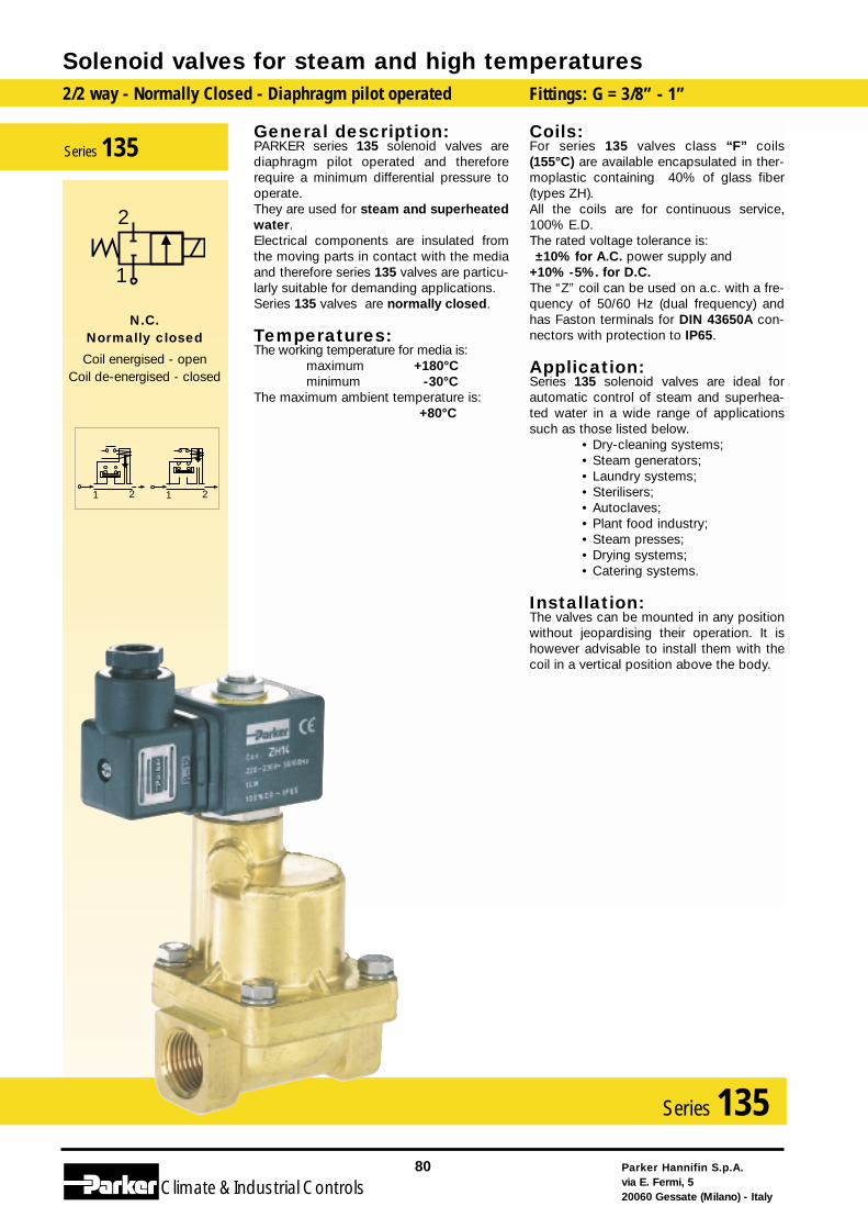
General description:PARKER series 135 solenoid valves arediaphragm pilot operated and thereforerequire a minimum differential pressure tooperate. They are used for steam and superheatedwater.Electrical components are insulated fromthe moving parts in contact with the mediaand therefore series 135 valves are particu-larly suitable for demanding applications.Series 135 valves are normally closed.
Temperatures:The working temperature for media is:
maximum +180°Cminimum -30°C
The maximum ambient temperature is:+80°C
Coils:For series 135 valves class “F” coils(155°C) are available encapsulated in ther-moplastic containing 40% of glass fiber(types ZH).All the coils are for continuous service,100% E.D.The rated voltage tolerance is:±10% for A.C. power supply and
+10% -5%. for D.C.The “Z” coil can be used on a.c. with a fre-quency of 50/60 Hz (dual frequency) andhas Faston terminals for DIN 43650A con-nectors with protection to IP65.
Application:Series 135 solenoid valves are ideal forautomatic control of steam and superhea-ted water in a wide range of applicationssuch as those listed below.
• Dry-cleaning systems;• Steam generators;• Laundry systems;• Sterilisers;• Autoclaves;• Plant food industry;• Steam presses;• Drying systems;• Catering systems.
Installation:The valves can be mounted in any positionwithout jeopardising their operation. It ishowever advisable to install them with thecoil in a vertical position above the body.
Solenoid valves for steam and high temperatures2/2 way - Normally Closed - Diaphragm pilot operated Fittings: G = 3/8” - 1”
Parker Hannifin S.p.A.via E. Fermi, 520060 Gessate (Milano) - Italy
80
Climate& Industrial Controls
Series 135
2121
2
1
N.C.Normally closed
Coil energised - openCoil de-energised - closed
Series 135
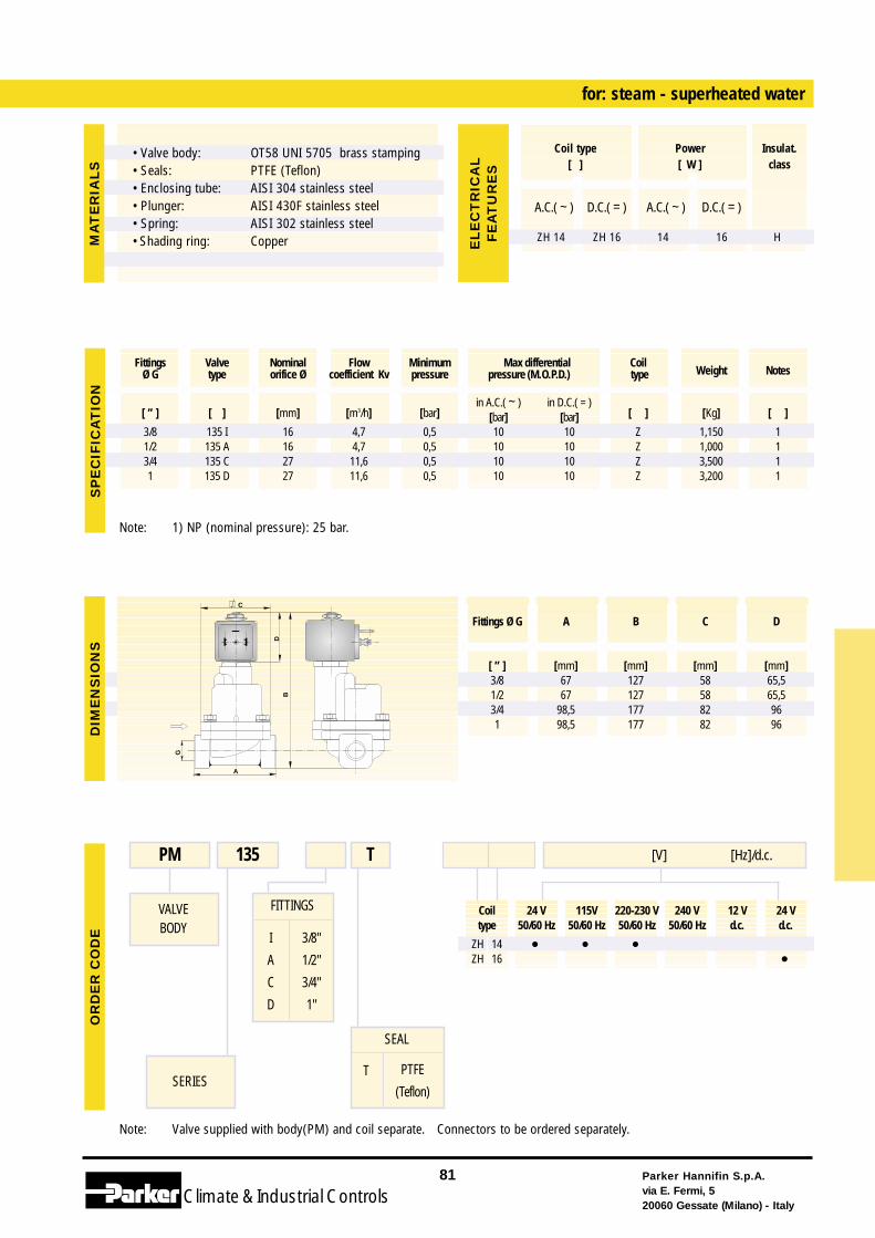
Coil 24 V 115V 220-230 V 240 V 12 V 24 Vtype 50/60 Hz 50/60 Hz 50/60 Hz 50/60 Hz d.c. d.c.
ZH 14 • • •ZH 16 •
Note: Valve supplied with body(PM) and coil separate. Connectors to be ordered separately.
FITTINGS
I
A
C
D
3/8"
1/2"
3/4"
1"
for: steam - superheated water
VALVEBODY
SERIES
PM 135 [V] [Hz]/d.c.T
SEAL
T PTFE
(Teflon)
Note: 1) NP (nominal pressure): 25 bar.
Parker Hannifin S.p.A.via E. Fermi, 520060 Gessate (Milano) - Italy
81
Climate& Industrial Controls
[ ” ] [ ] [mm] [m3/h] [bar]in A.C.( ~ ) in D.C.( = )
[ ] [Kg] [ ][bar] [bar]3/8 135 I 16 4,7 0,5 10 10 Z 1,150 11/2 135 A 16 4,7 0,5 10 10 Z 1,000 13/4 135 C 27 11,6 0,5 10 10 Z 3,500 11 135 D 27 11,6 0,5 10 10 Z 3,200 1
Fittings Valve Nominal Flow Minimum Max differential CoilWeight NotesØ G type orifice Ø coefficient Kv pressure pressure (M.O.P.D.) type
A
G
BD
C
SP
EC
IFIC
AT
ION
DIM
EN
SIO
NS
OR
DE
RC
OD
E
A.C.( ~ ) D.C.( = ) A.C.( ~ ) D.C.( = )
ZH 14 ZH 16 14 16 H
Coil type Power Insulat.[ ] [ W ] class
EL
EC
TR
ICA
LF
EA
TU
RE
S
Fittings Ø G A B C D
[ ” ] [mm] [mm] [mm] [mm]3/8 67 127 58 65,51/2 67 127 58 65,53/4 98,5 177 82 961 98,5 177 82 96
MA
TE
RIA
LS
• Valve body:• Seals:• Enclosing tube:• Plunger:• Spring:• Shading ring:
OT58 UNI 5705 brass stampingPTFE (Teflon)AISI 304 stainless steelAISI 430F stainless steelAISI 302 stainless steelCopper
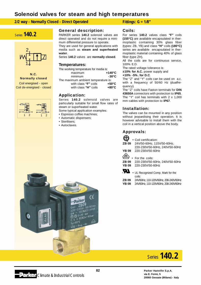
General description:PARKER series 140.2 solenoid valves aredirect operated and do not require a mini-mum differential pressure to operate. They are used for general applications withmedia such as steam and superheatedwater.Series 140.2 valves are normally closed.
Temperatures:The working temperature for media is:
maximum +140°Cminimum -30°C
The maximum ambient temperature is:with class “F” coils +50°Cwith class “H” coils +80°C
Application:Series 140.2 solenoid valves areparticularly suitable for small flow rates ofsteam or superheated water.Some typical application examples:• Espresso coffee machines;• Automatic dispensers;• Sterilisers;• Autoclaves.
Coils:For series 140.2 valves class “F” coils(155°C) are available encapsulated in ther-moplastic containing 30% glass fiber(types: ZB, YB) and class “H” coils (180°C)series are available encapsulated in ther-moplastic material containing 40% of glassfiber (type ZH).All the coils are for continuous service,100% E.D.The rated voltage tolerance is:±10% for A.C. power supply and+10% -5%. for D.C.The “Z” and “Y” coils can be used on a.c.with a frequency of 50/60 Hz (dualfre-quency).The “Z” coils have Faston terminals for DIN43650A connectors with protection to IP65.The “Y” coil has terminals with 2 x 1,000mm cables with protection to IP67.
Installation:The valves can be mounted in any positionwithout jeopardising their operation. It ishowever advisable to install them with thecoil in a vertical position above the body.
Approvals:
• Coil certification:ZB 09 24V/50-60Hz, 115V/50-60Hz,
220-230V/50-60Hz, 240V/50-60HzYB 09 220-230V/50-60Hz
• For the coils:ZB 09 220-230V/50-60Hz, 240V/50-60HzYB 09 220-230V/50-60Hz
• UL Recognized Comp. Mark for thecoils:
ZB 09 24V/60Hz, 110-120V/60Hz, 208-240V/60HzYB 09 24V/60Hz, 110-120V/60Hz, 208-240V/60Hz
Solenoid valves for steam and high temperatures2/2 way - Normally Closed - Direct Operated Fittings: G = 1/8”
Parker Hannifin S.p.A.via E. Fermi, 520060 Gessate (Milano) - Italy
82
Climate& Industrial Controls
Series 140.2
2121
2
1
N.C.Normally closed
Coil energised - openCoil de-energised - closed
Series 140.2
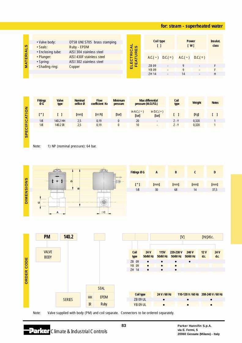
Coil 24 V 115V 220-230 V 240 V 12 V 24 Vtype 50/60 Hz 50/60 Hz 50/60 Hz 50/60 Hz d.c. d.c.
ZB 09 • • • •YB 09 • • •ZH 14 • • •
Coil type 24 V / 60 Hz 110-120 V / 60 Hz 208-240 V / 60 Hz
ZB 09 UL • • •YB 09 UL • • •
Note: Valve supplied with body (PM) and coil separate. Connectors to be ordered separately.
for: steam - superheated water
VALVEBODY
SERIES
PM 140.2 [V] [Hz]/d.c.
Note: 1) NP (nominal pressure): 64 bar.
Parker Hannifin S.p.A.via E. Fermi, 520060 Gessate (Milano) - Italy
83
Climate& Industrial Controls
[ ” ] [ ] [mm] [m3/h] [bar]in A.C.( ~ ) in D.C.( = )
[ ] [Kg] [ ][bar] [bar]
1/8 140.2 HH 2,5 0,19 0 20 - Z - Y 0,320 11/8 140.2 IR 2,5 0,19 0 10 - Z - Y 0,320 1
Fittings Valve Nominal Flow Minimum Max differential CoilWeight NotesØ G type orifice Ø coefficient Kv pressure pressure (M.O.P.D.) type
G
B
CA
D
SP
EC
IFIC
AT
ION
DIM
EN
SIO
NS
OR
DE
RC
OD
E
A.C.( ~ ) D.C.( = ) A.C.( ~ ) D.C.( = )
ZB 09 - 9 - FYB 09 - 9 - FZH 14 - 14 - H
Coil type Power Insulat.[ ] [ W ] class
EL
EC
TR
ICA
LF
EA
TU
RE
S
Fittings Ø G A B C D
[ ” ] [mm] [mm] [mm] [mm]
1/8 30 68 14 37,5
MA
TE
RIA
LS
SEAL
HH
IR
EPDM
Ruby
• Valve body:• Seals:• Enclosing tube:• Plunger:• Spring:• Shading ring:
OT58 UNI 5705 brass stampingRuby - EPDMAISI 304 stainless steelAISI 430F stainless steelAISI 302 stainless steelCopper
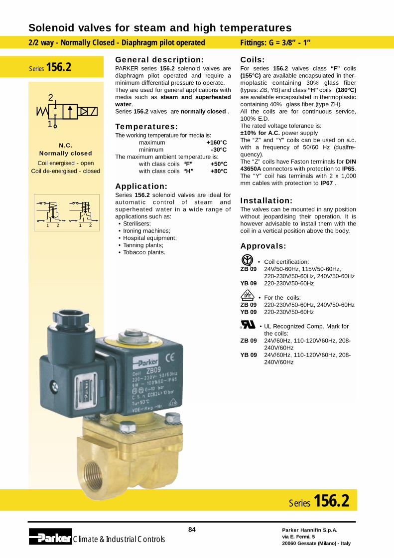
General description:PARKER series 156.2 solenoid valves arediaphragm pilot operated and require aminimum differential pressure to operate. They are used for general applications withmedia such as steam and superheatedwater.Series 156.2 valves are normally closed .
Temperatures:The working temperature for media is:
maximum +160°Cminimum -30°C
The maximum ambient temperature is:with class coils “F” +50°Cwith class coils “H” +80°C
Application:Series 156.2 solenoid valves are ideal forautomatic control of steam andsuperheated water in a wide range ofapplications such as:• Sterilisers;• Ironing machines;• Hospital equipment;• Tanning plants;• Tobacco plants.
Coils:For series 156.2 valves class “F” coils(155°C) are available encapsulated in ther-moplastic containing 30% glass fiber(types: ZB, YB) and class “H” coils (180°C)are available encapsulated in thermoplasticcontaining 40% glass fiber (type ZH).All the coils are for continuous service,100% E.D.The rated voltage tolerance is:±10% for A.C. power supply The “Z” and “Y” coils can be used on a.c.with a frequency of 50/60 Hz (dualfre-quency).The “Z” coils have Faston terminals for DIN43650A connectors with protection to IP65.The “Y” coil has terminals with 2 x 1,000mm cables with protection to IP67 .
Installation:The valves can be mounted in any positionwithout jeopardising their operation. It ishowever advisable to install them with thecoil in a vertical position above the body.
Approvals:
• Coil certification:ZB 09 24V/50-60Hz, 115V/50-60Hz,
220-230V/50-60Hz, 240V/50-60HzYB 09 220-230V/50-60Hz
• For the coils:ZB 09 220-230V/50-60Hz, 240V/50-60HzYB 09 220-230V/50-60Hz
• UL Recognized Comp. Mark forthe coils:
ZB 09 24V/60Hz, 110-120V/60Hz, 208-240V/60Hz
YB 09 24V/60Hz, 110-120V/60Hz, 208-240V/60Hz
Solenoid valves for steam and high temperatures2/2 way - Normally Closed - Diaphragm pilot operated Fittings: G = 3/8” - 1”
Parker Hannifin S.p.A.via E. Fermi, 520060 Gessate (Milano) - Italy
84
Climate& Industrial Controls
Series 156.2
1 21 2
2
1
N.C.Normally closed
Coil energised - openCoil de-energised - closed
Series 156.2
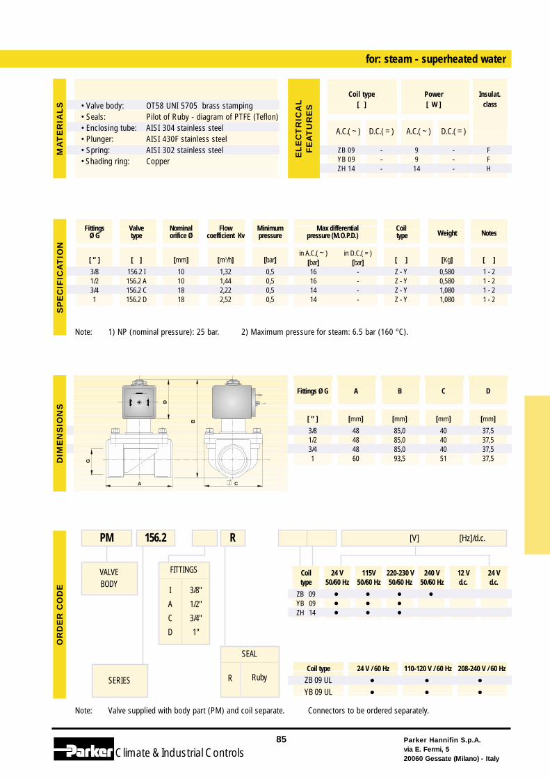
Coil 24 V 115V 220-230 V 240 V 12 V 24 Vtype 50/60 Hz 50/60 Hz 50/60 Hz 50/60 Hz d.c. d.c.
ZB 09 • • • •YB 09 • • •ZH 14 • • •
Coil type 24 V / 60 Hz 110-120 V / 60 Hz 208-240 V / 60 Hz
ZB 09 UL • • •YB 09 UL • • •
Note: Valve supplied with body part (PM) and coil separate. Connectors to be ordered separately.
FITTINGS
I
A
C
D
3/8"
1/2"
3/4"
1"
for: steam - superheated water
VALVEBODY
SERIES
PM 156.2 [V] [Hz]/d.c.R
SEAL
R Ruby
Note: 1) NP (nominal pressure): 25 bar. 2) Maximum pressure for steam: 6.5 bar (160 °C).
Parker Hannifin S.p.A.via E. Fermi, 520060 Gessate (Milano) - Italy
85
Climate& Industrial Controls
[ ” ] [ ] [mm] [m3/h] [bar]in A.C.( ~ ) in D.C.( = )
[ ] [Kg] [ ][bar] [bar]3/8 156.2 I 10 1,32 0,5 16 - Z - Y 0,580 1 - 21/2 156.2 A 10 1,44 0,5 16 - Z - Y 0,580 1 - 23/4 156.2 C 18 2,22 0,5 14 - Z - Y 1,080 1 - 21 156.2 D 18 2,52 0,5 14 - Z - Y 1,080 1 - 2
Fittings Valve Nominal Flow Minimum Max differential CoilWeight NotesØ G type orifice Ø coefficient Kv pressure pressure (M.O.P.D.) type
G
CA
B
D
SP
EC
IFIC
AT
ION
DIM
EN
SIO
NS
OR
DE
RC
OD
E
Fittings Ø G A B C D
[ ” ] [mm] [mm] [mm] [mm]
3/8 48 85,0 40 37,51/2 48 85,0 40 37,53/4 48 85,0 40 37,51 60 93,5 51 37,5
MA
TE
RIA
LS
A.C.( ~ ) D.C.( = ) A.C.( ~ ) D.C.( = )
ZB 09 - 9 - FYB 09 - 9 - FZH 14 - 14 - H
Coil type Power Insulat.[ ] [ W ] class
EL
EC
TR
ICA
LF
EA
TU
RE
S• Valve body:• Seals:• Enclosing tube:• Plunger:• Spring:• Shading ring:
OT58 UNI 5705 brass stampingPilot of Ruby - diagram of PTFE (Teflon)AISI 304 stainless steelAISI 430F stainless steelAISI 302 stainless steelCopper
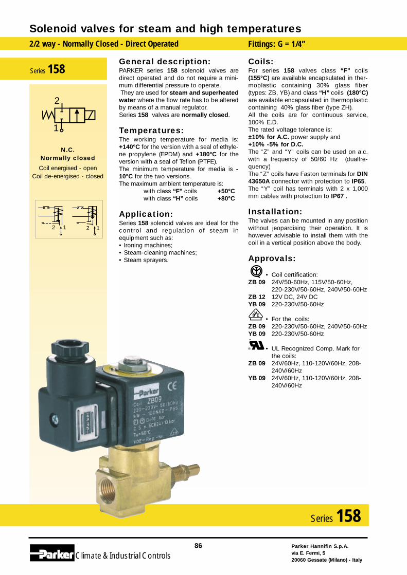
General description:PARKER series 158 solenoid valves aredirect operated and do not require a mini-mum differential pressure to operate. They are used for steam and superheatedwater where the flow rate has to be alteredby means of a manual regulator.Series 158 valves are normally closed.
Temperatures:The working temperature for media is:+140°C for the version with a seal of ethyle-ne propylene (EPDM) and +180°C for theversion with a seal of Teflon (PTFE).The minimum temperature for media is -10°C for the two versions.The maximum ambient temperature is:
with class “F” coils +50°Cwith class “H” coils +80°C
Application:Series 158 solenoid valves are ideal for thecontrol and regulation of steam inequipment such as:• Ironing machines;• Steam-cleaning machines;• Steam sprayers.
Coils:For series 158 valves class “F” coils(155°C) are available encapsulated in ther-moplastic containing 30% glass fiber(types: ZB, YB) and class “H” coils (180°C)are available encapsulated in thermoplasticcontaining 40% glass fiber (type ZH).All the coils are for continuous service,100% E.D.The rated voltage tolerance is:±10% for A.C. power supply and+10% -5% for D.C.The “Z” and “Y” coils can be used on a.c.with a frequency of 50/60 Hz (dualfre-quency)The “Z” coils have Faston terminals for DIN43650A connector with protection to IP65.The “Y” coil has terminals with 2 x 1,000mm cables with protection to IP67 .
Installation:The valves can be mounted in any positionwithout jeopardising their operation. It ishowever advisable to install them with thecoil in a vertical position above the body.
Approvals:
• Coil certification:ZB 09 24V/50-60Hz, 115V/50-60Hz,
220-230V/50-60Hz, 240V/50-60HzZB 12 12V DC, 24V DCYB 09 220-230V/50-60Hz
• For the coils:ZB 09 220-230V/50-60Hz, 240V/50-60HzYB 09 220-230V/50-60Hz
• UL Recognized Comp. Mark forthe coils:
ZB 09 24V/60Hz, 110-120V/60Hz, 208-240V/60Hz
YB 09 24V/60Hz, 110-120V/60Hz, 208-240V/60Hz
Solenoid valves for steam and high temperatures2/2 way - Normally Closed - Direct Operated Fittings: G = 1/4”
Parker Hannifin S.p.A.via E. Fermi, 520060 Gessate (Milano) - Italy
86
Climate& Industrial Controls
Series 158
2 12 1
2
1
N.C.Normally closed
Coil energised - openCoil de-energised - closed
Series 158
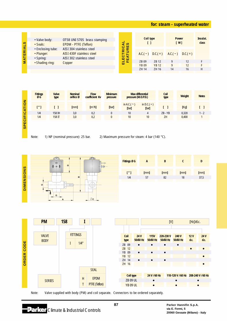
Coil 24 V 115V 220-230 V 240 V 12 V 24 Vtype 50/60 Hz 50/60 Hz 50/60 Hz 50/60 Hz d.c. d.c.
ZB 09 • • • •ZB 12 • •YB 09 • • •YB 12 •ZH 14 • • •ZH 16 •
Coil type 24 V / 60 Hz 110-120 V / 60 Hz 208-240 V / 60 Hz
ZB 09 UL • • •YB 09 UL • • •
Note: Valve supplied with body (PM) and coil separate. Connectors to be ordered separately.
FITTINGS
I 1/4"
for: steam - superheated water
VALVEBODY
SERIES
PM 158 I [V] [Hz]/d.c.
Note: 1) NP (nominal pressure): 25 bar. 2) Maximum pressure for steam: 4 bar (140 °C).
Parker Hannifin S.p.A.via E. Fermi, 520060 Gessate (Milano) - Italy
87
Climate& Industrial Controls
[ ” ] [ ] [mm] [m3/h] [bar]in A.C.( ~ ) in D.C.( = )
[ ] [Kg] [ ][bar] [bar]
1/4 158 IH 3,0 0,2 0 10 4 ZB - YB 0,320 1 - 21/4 158 IT 3,0 0,2 0 10 10 ZH 0,400 1
Fittings Valve Nominal Flow Minimum Max differential CoilWeight NotesØ G type orifice Ø coefficient Kv pressure pressure (M.O.P.D.) type
G
B
A
G
C
D
SP
EC
IFIC
AT
ION
DIM
EN
SIO
NS
OR
DE
RC
OD
E
A.C.( ~ ) D.C.( = ) A.C.( ~ ) D.C.( = )
ZB 09 ZB 12 9 12 FYB 09 YB 12 9 12 FZH 14 ZH 16 14 16 H
Coil type Power Insulat.[ ] [ W ] class
EL
EC
TR
ICA
LF
EA
TU
RE
S
Fittings Ø G A B C D
[ ” ] [mm] [mm] [mm] [mm]
1/4 57 82 18 37,5
MA
TE
RIA
LS
SEAL
H
T
EPDM
PTFE (Teflon)
• Valve body:• Seals:• Enclosing tube:• Plunger:• Spring:• Shading ring:
OT58 UNI 5705 brass stampingEPDM - PTFE (Teflon)AISI 304 stainless steelAISI 430F stainless steelAISI 302 stainless steelCopper
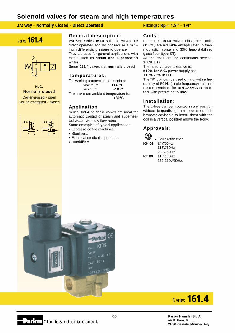
General description:PARKER series 161.4 solenoid valves aredirect operated and do not require a mini-mum differential pressure to operate. They are used for general applications withmedia such as steam and superheatedwater. Series 161.4 valves are normally closed.
Temperatures:The working temperature for media is:
maximum +140°Cminimum -10°C
The maximum ambient temperature is:+80°C
ApplicationSeries 161.4 solenoid valves are ideal forautomatic control of steam and superhea-ted water with low flow rates. Some examples of typical applications:• Espresso coffee machines;• Sterilisers;• Electrical medical equipment;• Humidifiers.
Coils:For series 161.4 valves class “F” coils(155°C) are available encapsulated in ther-moplastic containing 30% heat-stabilisedglass fiber (type KT).All the coils are for continuous service,100% E.D.The rated voltage tolerance is:±10% for A.C. power supply and+10% -5% in D.C.The “K” coil can be used on a.c. with a fre-quency of 50 Hz (single frequency) and hasFaston terminals for DIN 43650A connec-tors with protection to IP65.
Installation:The valves can be mounted in any positionwithout jeopardising their operation. It ishowever advisable to install them with thecoil in a vertical position above the body.
Approvals:
• Coil certification:KH 09 24V/50Hz
115V/50Hz230V/50Hz.
KT 09 115V/50Hz220-230V/50Hz.
Solenoid valves for steam and high temperatures2/2 way - Normally Closed - Direct Operated Fittings: Rp = 1/8” - 1/4”
Parker Hannifin S.p.A.via E. Fermi, 520060 Gessate (Milano) - Italy
88
Climate& Industrial Controls
Series 161.4
2121
2
1
N.C.Normally closed
Coil energised - openCoil de-energised - closed
Series 161.4
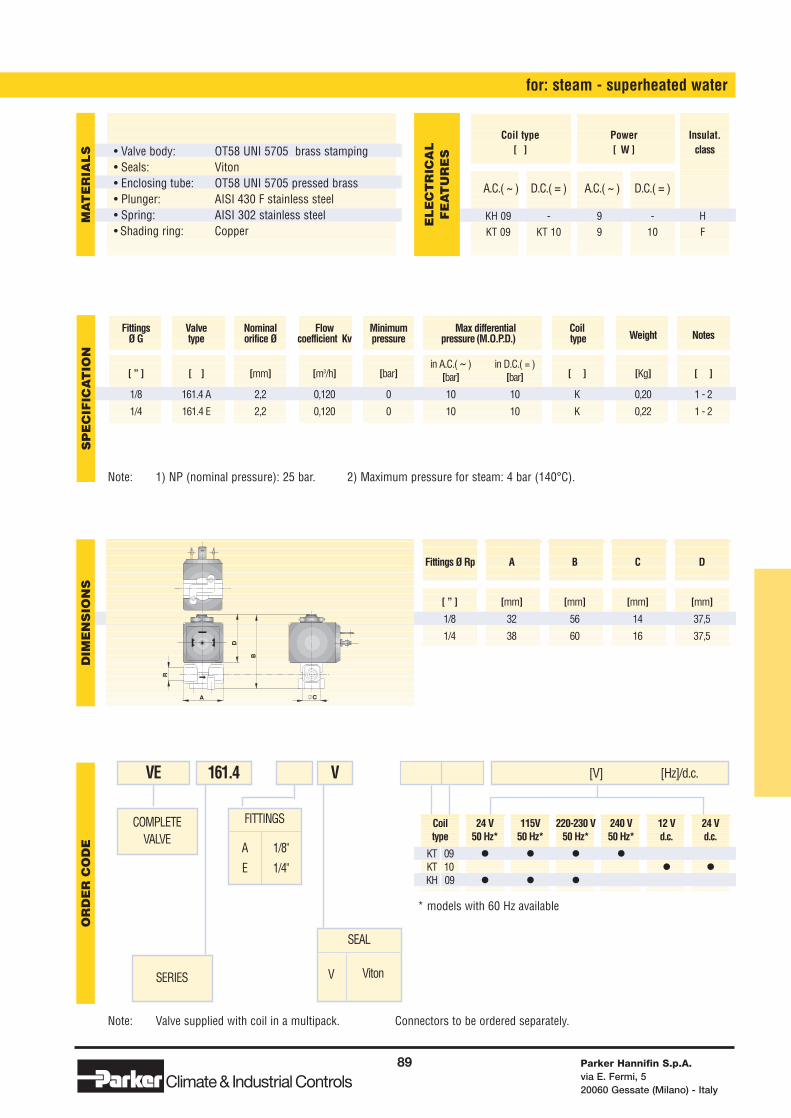
Coil 24 V 115V 220-230 V 240 V 12 V 24 Vtype 50 Hz* 50 Hz* 50 Hz* 50 Hz* d.c. d.c.
KT 09 • • • •KT 10 • •KH 09 • • •
Note: Valve supplied with coil in a multipack. Connectors to be ordered separately.
* models with 60 Hz available
FITTINGS
A
E
1/8"
1/4"
for: steam - superheated water
COMPLETEVALVE
SERIES
VE 161.4 [V] [Hz]/d.c.V
SEAL
V Viton
Note: 1) NP (nominal pressure): 25 bar. 2) Maximum pressure for steam: 4 bar (140°C).
Parker Hannifin S.p.A.via E. Fermi, 520060 Gessate (Milano) - Italy
89
Climate& Industrial Controls
[ ” ] [ ] [mm] [m3/h] [bar]in A.C.( ~ ) in D.C.( = )
[ ] [Kg] [ ][bar] [bar]
1/8 161.4 A 2,2 0,120 0 10 10 K 0,20 1 - 2
1/4 161.4 E 2,2 0,120 0 10 10 K 0,22 1 - 2
Fittings Valve Nominal Flow Minimum Max differential CoilWeight NotesØ G type orifice Ø coefficient Kv pressure pressure (M.O.P.D.) type
CA
R
B
D
SP
EC
IFIC
AT
ION
DIM
EN
SIO
NS
OR
DE
RC
OD
E
Fittings Ø Rp A B C D
[ ” ] [mm] [mm] [mm] [mm]
1/8 32 56 14 37,5
1/4 38 60 16 37,5
MA
TE
RIA
LS
A.C.( ~ ) D.C.( = ) A.C.( ~ ) D.C.( = )
KH 09 - 9 - HKT 09 KT 10 9 10 F
Coil type Power Insulat.[ ] [ W ] class
EL
EC
TR
ICA
LF
EA
TU
RE
S• Valve body:• Seals:• Enclosing tube:• Plunger:• Spring:• Shading ring:
OT58 UNI 5705 brass stampingVitonOT58 UNI 5705 pressed brassAISI 430 F stainless steelAISI 302 stainless steelCopper
Solenoid valves for steam and high temperatures
Parker Hannifin S.p.A.via E. Fermi, 520060 Gessate (Milano) - Italy
90
Climate& Industrial ControlsClimate& Industrial Controls
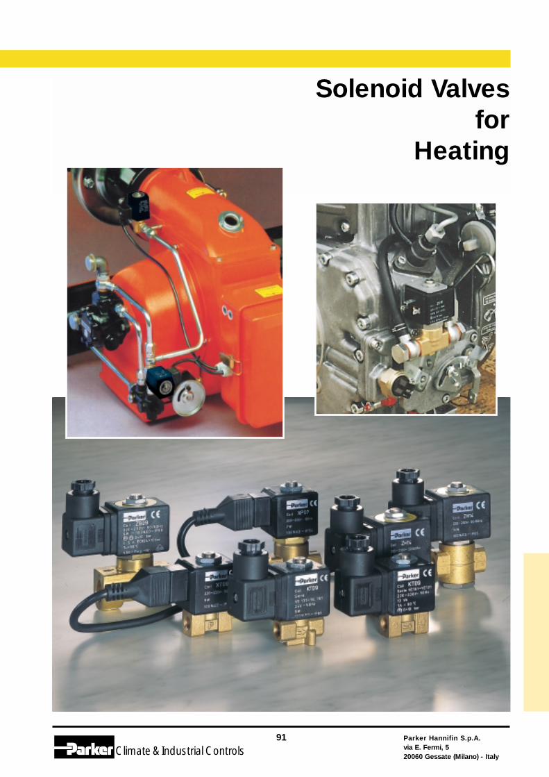
Parker Hannifin S.p.A.via E. Fermi, 520060 Gessate (Milano) - Italy
91
Climate& Industrial Controls
Solenoid Valvesfor
Heating
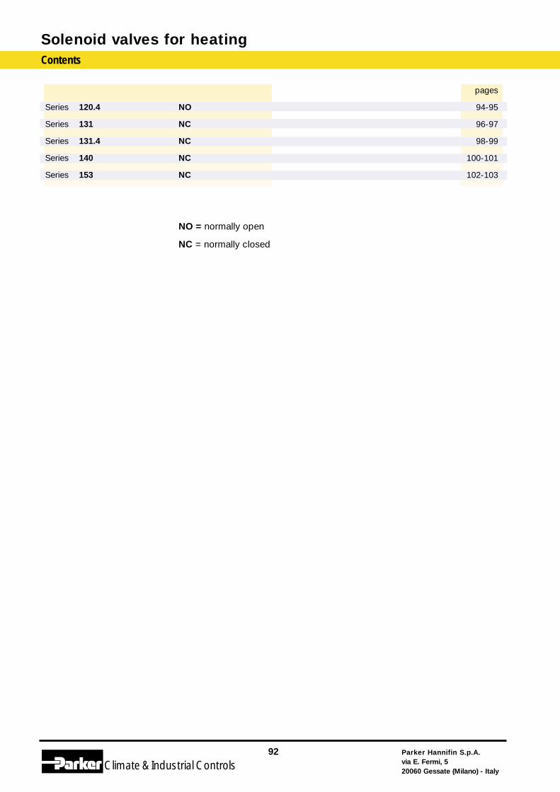
Solenoid valves for heatingContents
Parker Hannifin S.p.A.via E. Fermi, 520060 Gessate (Milano) - Italy
92
Climate& Industrial Controls
Series 120.4
Series 131
Series 131.4
Series 140
Series 153
NO
NC
NC
NC
NC
NO = normally open
NC = normally closed
pages
94-95
96-97
98-99
100-101
102-103
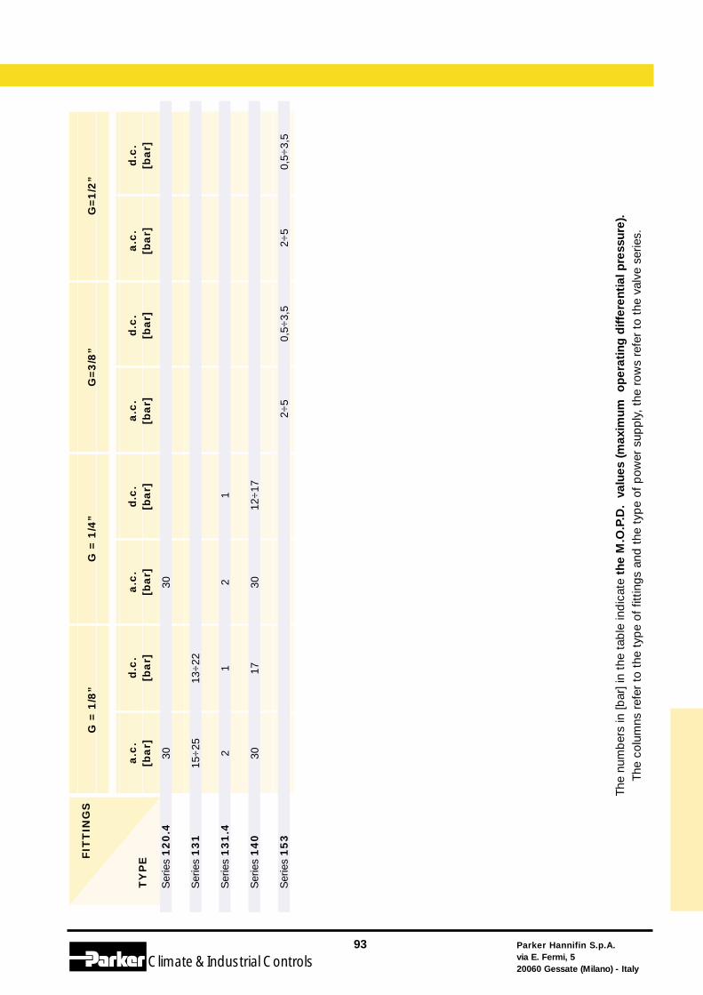
Parker Hannifin S.p.A.via E. Fermi, 520060 Gessate (Milano) - Italy
93
Climate& Industrial Controls
The
num
ber
s in
[bar
] in
the
tab
le in
dic
ate
the
M.O
.P.D
. va
lues
(m
axim
um
op
erat
ing
diff
eren
tial
pre
ssur
e).
The
colu
mns
ref
er t
o th
e ty
pe
of f
ittin
gs a
nd t
he t
ype
of p
ower
sup
ply
, th
e ro
ws
refe
r to
the
val
ve s
erie
s.
a.c
.[b
ar]
d.c
.[b
ar]
a.c
.[b
ar]
d.c
.[b
ar]
a.c
.[b
ar]
d.c
.[b
ar]
a.c
.[b
ar]
d.c
.[b
ar]
G=3
/8”
G=1
/2”
FIT
TIN
GS
TY
PE
G =
1/8
”G
= 1
/4”
Ser
ies
120.4
Ser
ies
131
Ser
ies
131.4
Ser
ies
140
Ser
ies
153
2÷5
0,5÷
3,5
2÷5
1
12÷
17
30 2 30
13÷
22 1 17
30
15÷
25 2 30
0,5÷
3,5
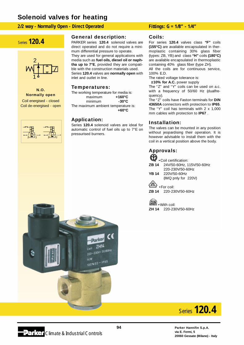
General description:PARKER series 120.4 solenoid valves aredirect operated and do not require a mini-mum differential pressure to operate. They are used for general applications withmedia such as fuel oils, diesel oil or naph-tha up to 7°E, provided they are compati-ble with the construction materials used. Series 120.4 valves are normally open withinlet and outlet in line.
Temperatures:The working temperature for media is:
maximum +160°Cminimum -30°C
The maximum ambient temperature is:+60°C
Application:Series 120.4 solenoid valves are ideal forautomatic control of fuel oils up to 7°E onpressurised burners.
Coils:For series 120.4 valves class “F” coils(155°C) are available encapsulated in ther-moplastic containing 30% glass fiber(types: ZB, YB) and class “H” coils (180°C)are available encapsulated in thermoplasticcontaining 40% glass fiber (type ZH).All the coils are for continuous service,100% E.D.The rated voltage tolerance is:
±10% for A.C. power supply The “Z” and “Y” coils can be used on a.c.with a frequency of 50/60 Hz (dualfre-quency).The “Z” coils have Faston terminals for DIN43650A connectors with protection to IP65.The “Y” coil has terminals with 2 x 1,000mm cables with protection to IP67 .
Installation:The valves can be mounted in any positionwithout jeopardising their operation. It ishowever advisable to install them with thecoil in a vertical position above the body.
Approvals:
•Coil certification:ZB 14 24V/50-60Hz, 115V/50-60Hz
220-230V/50-60HzYB 14 220V/50-60Hz
(IMQ pnly for 220V)
•For coil:ZB 14 220-230V/50-60Hz
•With coil:ZH 14 220-230V/50-60Hz
Solenoid valves for heating2/2 way - Normally Open - Direct Operated Fittings: G = 1/8” - 1/4”
Parker Hannifin S.p.A.via E. Fermi, 520060 Gessate (Milano) - Italy
94
Climate& Industrial Controls
Series 120.4
2121
2
1
N.O.Normally open
Coil energised - closedCoil de-energised - open
Series 120.4
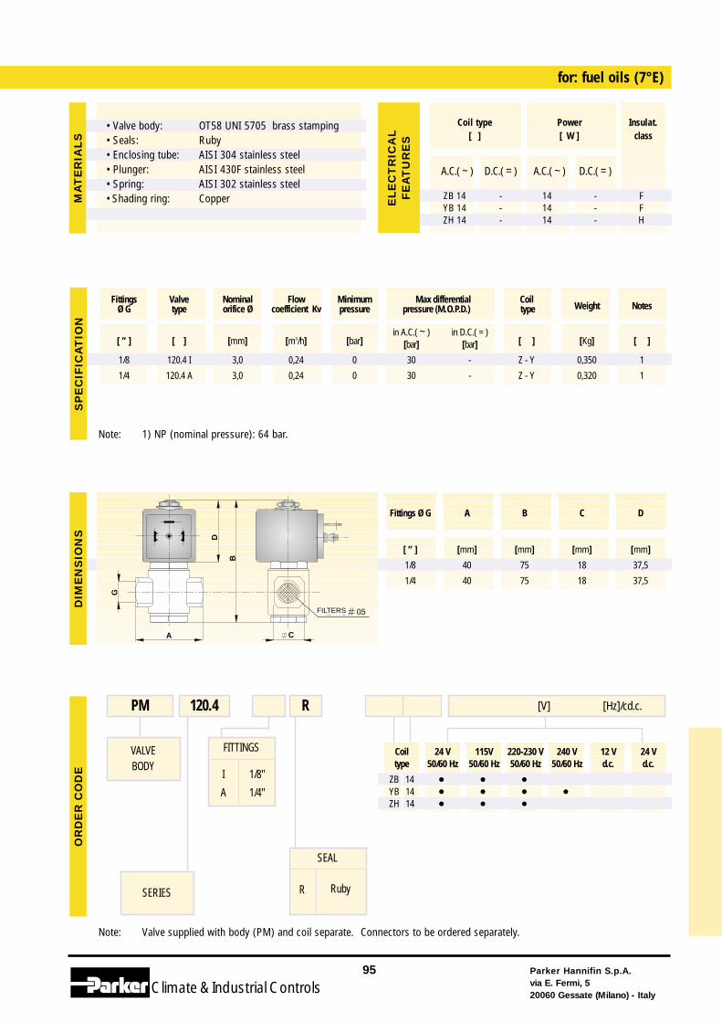
Coil 24 V 115V 220-230 V 240 V 12 V 24 Vtype 50/60 Hz 50/60 Hz 50/60 Hz 50/60 Hz d.c. d.c.
ZB 14 • • •YB 14 • • • •ZH 14 • • •
Note: Valve supplied with body (PM) and coil separate. Connectors to be ordered separately.
FITTINGS
I
A
1/8"
1/4"
for: fuel oils (7°E)
VALVEBODY
SERIES
PM 120.4 [V] [Hz]/cd.c.R
SEAL
R Ruby
Note: 1) NP (nominal pressure): 64 bar.
Parker Hannifin S.p.A.via E. Fermi, 520060 Gessate (Milano) - Italy
95
Climate& Industrial Controls
[ ” ] [ ] [mm] [m3/h] [bar]in A.C.( ~ ) in D.C.( = )
[ ] [Kg] [ ][bar] [bar]
1/8 120.4 I 3,0 0,24 0 30 - Z - Y 0,350 1
1/4 120.4 A 3,0 0,24 0 30 - Z - Y 0,320 1
Fittings Valve Nominal Flow Minimum Max differential CoilWeight NotesØ G type orifice Ø coefficient Kv pressure pressure (M.O.P.D.) type
G
B
CA
D
FILTRO 0.5
SP
EC
IFIC
AT
ION
DIM
EN
SIO
NS
OR
DE
RC
OD
E
A.C.( ~ ) D.C.( = ) A.C.( ~ ) D.C.( = )
ZB 14 - 14 - FYB 14 - 14 - FZH 14 - 14 - H
EL
EC
TR
ICA
LF
EA
TU
RE
S
Fittings Ø G A B C D
[ ” ] [mm] [mm] [mm] [mm]
1/8 40 75 18 37,5
1/4 40 75 18 37,5
MA
TE
RIA
LS
Coil type Power Insulat.[ ] [ W ] class
• Valve body:• Seals:• Enclosing tube:• Plunger:• Spring:• Shading ring:
OT58 UNI 5705 brass stampingRubyAISI 304 stainless steelAISI 430F stainless steelAISI 302 stainless steelCopper
FILTERS
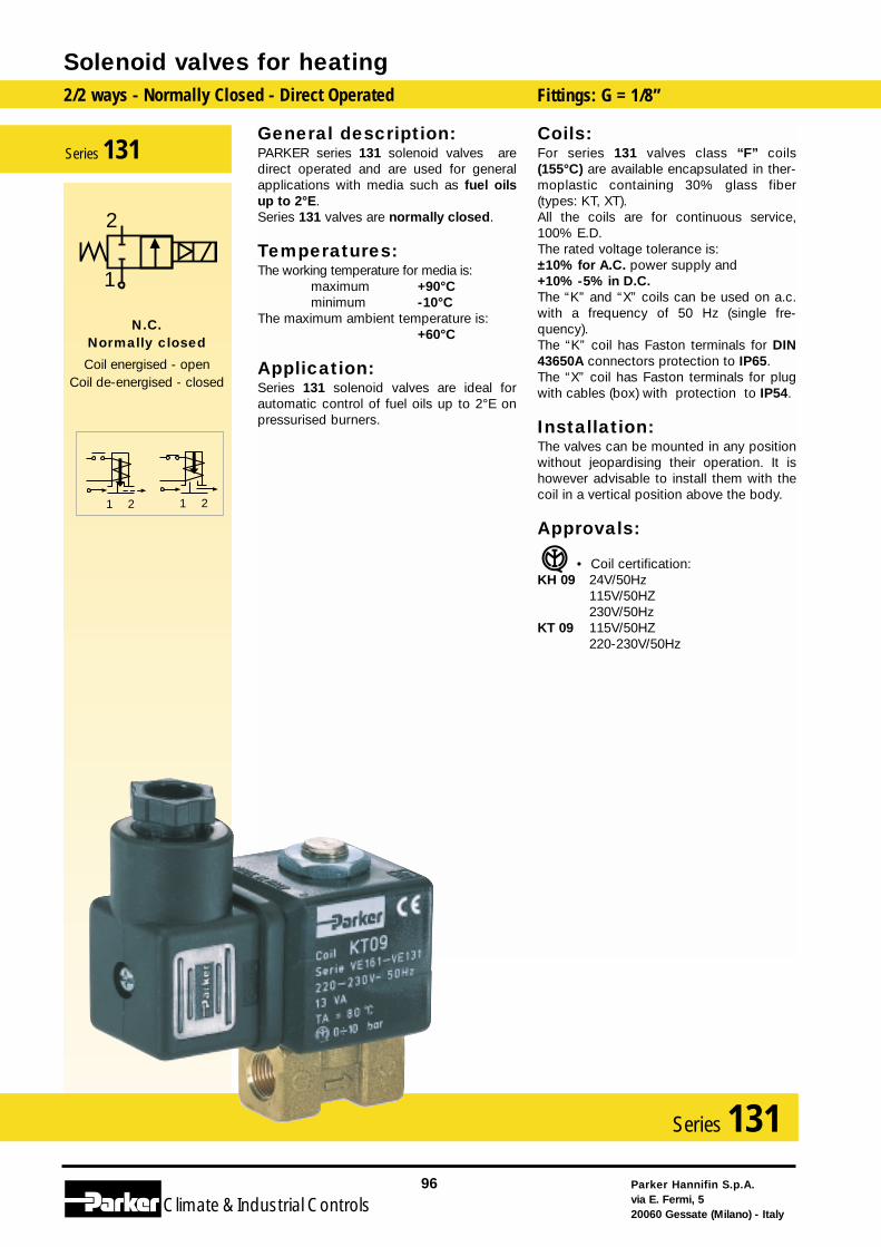
General description:PARKER series 131 solenoid valves aredirect operated and are used for generalapplications with media such as fuel oilsup to 2°E. Series 131 valves are normally closed.
Temperatures:The working temperature for media is:
maximum +90°Cminimum -10°C
The maximum ambient temperature is:+60°C
Application:Series 131 solenoid valves are ideal forautomatic control of fuel oils up to 2°E onpressurised burners.
Coils:For series 131 valves class “F” coils(155°C) are available encapsulated in ther-moplastic containing 30% glass fiber(types: KT, XT). All the coils are for continuous service,100% E.D.The rated voltage tolerance is: ±10% for A.C. power supply and+10% -5% in D.C.The “K” and “X” coils can be used on a.c.with a frequency of 50 Hz (single fre-quency).The “K” coil has Faston terminals for DIN43650A connectors protection to IP65.The “X” coil has Faston terminals for plugwith cables (box) with protection to IP54.
Installation:The valves can be mounted in any positionwithout jeopardising their operation. It ishowever advisable to install them with thecoil in a vertical position above the body.
Approvals:
• Coil certification:KH 09 24V/50Hz
115V/50HZ230V/50Hz
KT 09 115V/50HZ220-230V/50Hz
Solenoid valves for heating2/2 ways - Normally Closed - Direct Operated Fittings: G = 1/8”
Parker Hannifin S.p.A.via E. Fermi, 520060 Gessate (Milano) - Italy
96
Climate& Industrial Controls
Series 131
2
1
N.C.Normally closed
Coil energised - openCoil de-energised - closed
Series 131
2121
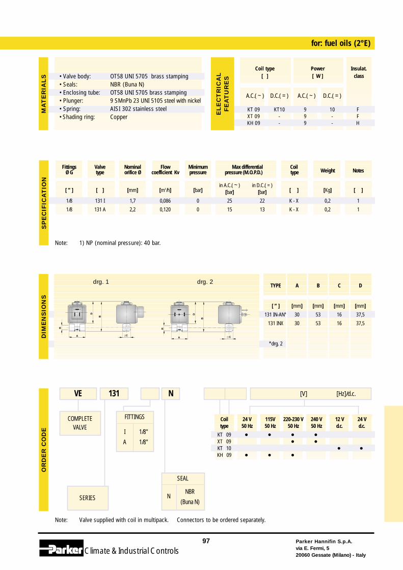
Coil 24 V 115V 220-230 V 240 V 12 V 24 Vtype 50 Hz 50 Hz 50 Hz 50 Hz d.c. d.c.
KT 09 • • • •XT 09 • •KT 10 • •KH 09 • • •
Note: Valve supplied with coil in multipack. Connectors to be ordered separately.
FITTINGS
I
A
1/8"
1/8"
for: fuel oils (2°E)
COMPLETEVALVE
SERIES
VE 131 [V] [Hz]/d.c.N
SEAL
NNBR
(Buna N)
Note: 1) NP (nominal pressure): 40 bar.
Parker Hannifin S.p.A.via E. Fermi, 520060 Gessate (Milano) - Italy
97
Climate& Industrial Controls
[ ” ] [ ] [mm] [m3/h] [bar]in A.C.( ~ ) in D.C.( = )
[ ] [Kg] [ ][bar] [bar]
1/8 131 I 1,7 0,086 0 25 22 K - X 0,2 1
1/8 131 A 2,2 0,120 0 15 13 K - X 0,2 1
Fittings Valve Nominal Flow Minimum Max differential CoilWeight NotesØ G type orifice Ø coefficient Kv pressure pressure (M.O.P.D.) type
SP
EC
IFIC
AT
ION
OR
DE
RC
OD
EM
AT
ER
IAL
S
A.C.( ~ ) D.C.( = ) A.C.( ~ ) D.C.( = )
KT 09 KT10 9 10 FXT 09 - 9 - FKH 09 - 9 - H
Coil type Power Insulat.[ ] [ W ] class
EL
EC
TR
ICA
LF
EA
TU
RE
S
CA
R
B
D
DIM
EN
SIO
NS
TYPE A B C D
[ ” ] [mm] [mm] [mm] [mm]
131 IN-AN* 30 53 16 37,5
131 INX 30 53 16 37,5
*drg. 2CA
R
B
D
drg. 1 drg. 2
• Valve body:• Seals:• Enclosing tube:• Plunger:• Spring:• Shading ring:
OT58 UNI 5705 brass stampingNBR (Buna N)OT58 UNI 5705 brass stamping9 SMnPb 23 UNI 5105 steel with nickelAISI 302 stainless steelCopper
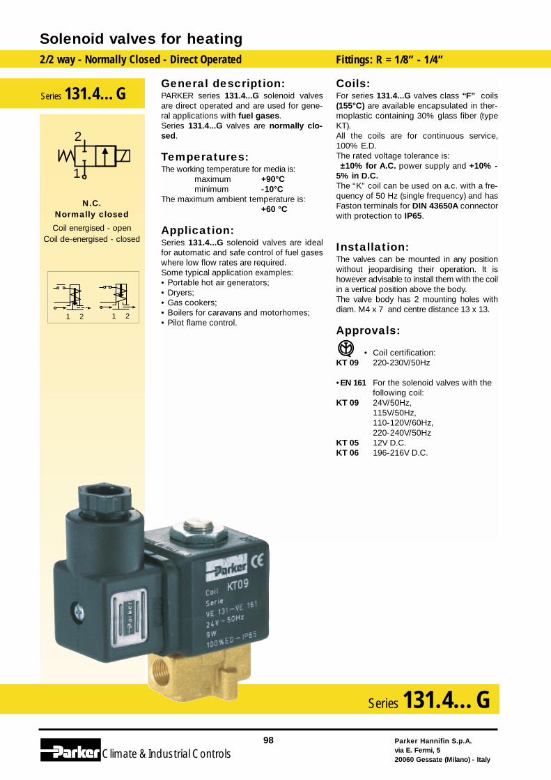
General description:PARKER series 131.4...G solenoid valvesare direct operated and are used for gene-ral applications with fuel gases.Series 131.4...G valves are normally clo-sed.
Temperatures:The working temperature for media is:
maximum +90°Cminimum -10°C
The maximum ambient temperature is:+60 °C
Application:Series 131.4...G solenoid valves are idealfor automatic and safe control of fuel gaseswhere low flow rates are required.Some typical application examples:• Portable hot air generators;• Dryers;• Gas cookers;• Boilers for caravans and motorhomes;• Pilot flame control.
Coils:For series 131.4...G valves class “F” coils(155°C) are available encapsulated in ther-moplastic containing 30% glass fiber (typeKT). All the coils are for continuous service,100% E.D.The rated voltage tolerance is: ±10% for A.C. power supply and +10% -
5% in D.C.The “K” coil can be used on a.c. with a fre-quency of 50 Hz (single frequency) and hasFaston terminals for DIN 43650A connectorwith protection to IP65.
Installation:The valves can be mounted in any positionwithout jeopardising their operation. It ishowever advisable to install them with the coilin a vertical position above the body.The valve body has 2 mounting holes withdiam. M4 x 7 and centre distance 13 x 13.
Approvals:
• Coil certification:KT 09 220-230V/50Hz
•EN 161 For the solenoid valves with thefollowing coil:
KT 09 24V/50Hz,115V/50Hz, 110-120V/60Hz, 220-240V/50Hz
KT 05 12V D.C.KT 06 196-216V D.C.
Solenoid valves for heating2/2 way - Normally Closed - Direct Operated Fittings: R = 1/8” - 1/4”
Parker Hannifin S.p.A.via E. Fermi, 520060 Gessate (Milano) - Italy
98
Climate& Industrial Controls
Series 131.4…G
2121
2
1
N.C.Normally closed
Coil energised - openCoil de-energised - closed
Series 131.4…G
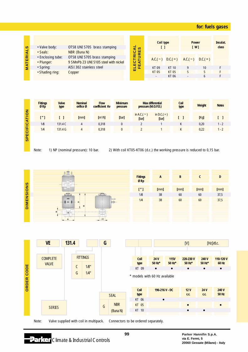
Coil 196-216 V - DC 12 V 24 V 240 Vtype c.c. c.c. 50 Hz
KT 06 •KT 05 • •KT 10 • •
Note: Valve supplied with coil in multipack. Connectors to be ordered separately.
FITTINGS
C
G
1/8"
1/4"
for: fuels gases
COMPLETEVALVE
SERIES
VE 131.4 G
SEAL
G NBR
(Buna N)
Note: 1) NP (nominal pressure): 10 bar. 2) With coil KT05-KT06 (d.c.) the working pressure is reduced to 0,15 bar.
Parker Hannifin S.p.A.via E. Fermi, 520060 Gessate (Milano) - Italy
99
Climate& Industrial Controls
[ ” ] [ ] [mm] [m3/h] [bar]in A.C.( ~ ) in D.C.( = )
[ ] [Kg] [ ][bar] [bar]
1/8 131.4 C 4 0,318 0 2 1 K 0,20 1 - 2
1/4 131.4 G 4 0,318 0 2 1 K 0,22 1 - 2
Fittings Valve Nominal Flow Minimum Max differential CoilWeight NotesØ Rp type orifice Ø coefficient Kv pressure pressure (M.O.P.D.) type
CA
R
B
D
SP
EC
IFIC
AT
ION
DIM
EN
SIO
NS
OR
DE
RC
OD
E
Fittings A B C DØ Rp
[ ” ] [mm] [mm] [mm] [mm]
1/8 38 60 60 37,5
1/4 38 60 60 37,5
MA
TE
RIA
LS
A.C.( ~ ) D.C.( = ) A.C.( ~ ) D.C.( = )
KT 09 KT 10 9 10 FKT 05 KT 05 5 5 F
- KT 06 - 6 F
Coil type Power Insulat.[ ] [ W ] class
EL
EC
TR
ICA
LF
EA
TU
RE
S• Valve body:• Seals:• Enclosing tube:• Plunger:• Spring:• Shading ring:
OT58 UNI 5705 brass stampingNBR (Buna N)OT58 UNI 5705 brass stamping9 SMnPb 23 UNI 5105 steel with nickelAISI 302 stainless steelCopper
Coil 24 V 115V 220-230 V 240 V 110-120 Vtype 50 Hz* 50 Hz* 50 Hz* 50 Hz* 60 Hz
KT 09 • • • • •
[V] [Hz]/d.c.
* models with 60 Hz available
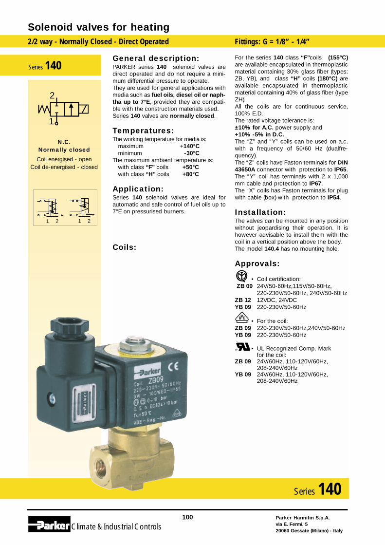
General description:PARKER series 140 solenoid valves aredirect operated and do not require a mini-mum differential pressure to operate. They are used for general applications withmedia such as fuel oils, diesel oil or naph-tha up to 7°E, provided they are compati-ble with the construction materials used. Series 140 valves are normally closed.
Temperatures:The working temperature for media is:
maximum +140°Cminimum -30°C
The maximum ambient temperature is:with class “F” coils +50°Cwith class “H” coils +80°C
Application:Series 140 solenoid valves are ideal forautomatic and safe control of fuel oils up to7°E on pressurised burners.
Coils:
For the series 140 class “F”coils (155°C)are available encapsulated in thermoplasticmaterial containing 30% glass fiber (types:ZB, YB), and class “H” coils (180°C) areavailable encapsulated in thermoplasticmaterial containing 40% of glass fiber (typeZH).All the coils are for continuous service,100% E.D.The rated voltage tolerance is:±10% for A.C. power supply and+10% -5% in D.C.The “Z” and “Y” coils can be used on a.c.with a frequency of 50/60 Hz (dualfre-quency).The “Z” coils have Faston terminals for DIN43650A connector with protection to IP65.The “Y” coil has terminals with 2 x 1,000mm cable and protection to IP67.The “X” coils has Faston terminals for plugwith cable (box) with protection to IP54.
Installation:The valves can be mounted in any positionwithout jeopardising their operation. It ishowever advisable to install them with thecoil in a vertical position above the body.The model 140.4 has no mounting hole.
Approvals:
• Coil certification:ZB 09 24V/50-60Hz,115V/50-60Hz,
220-230V/50-60Hz, 240V/50-60HzZB 12 12VDC, 24VDC YB 09 220-230V/50-60Hz
• For the coil:ZB 09 220-230V/50-60Hz,240V/50-60HzYB 09 220-230V/50-60Hz
• UL Recognized Comp. Markfor the coil:
ZB 09 24V/60Hz, 110-120V/60Hz,208-240V/60Hz
YB 09 24V/60Hz, 110-120V/60Hz,208-240V/60Hz
Solenoid valves for heating2/2 way - Normally Closed - Direct Operated Fittings: G = 1/8” - 1/4”
Parker Hannifin S.p.A.via E. Fermi, 520060 Gessate (Milano) - Italy
100
Climate& Industrial Controls
Series 140
2121
2
1
N.C.Normally closed
Coil energised - openCoil de-energised - closed
Series 140
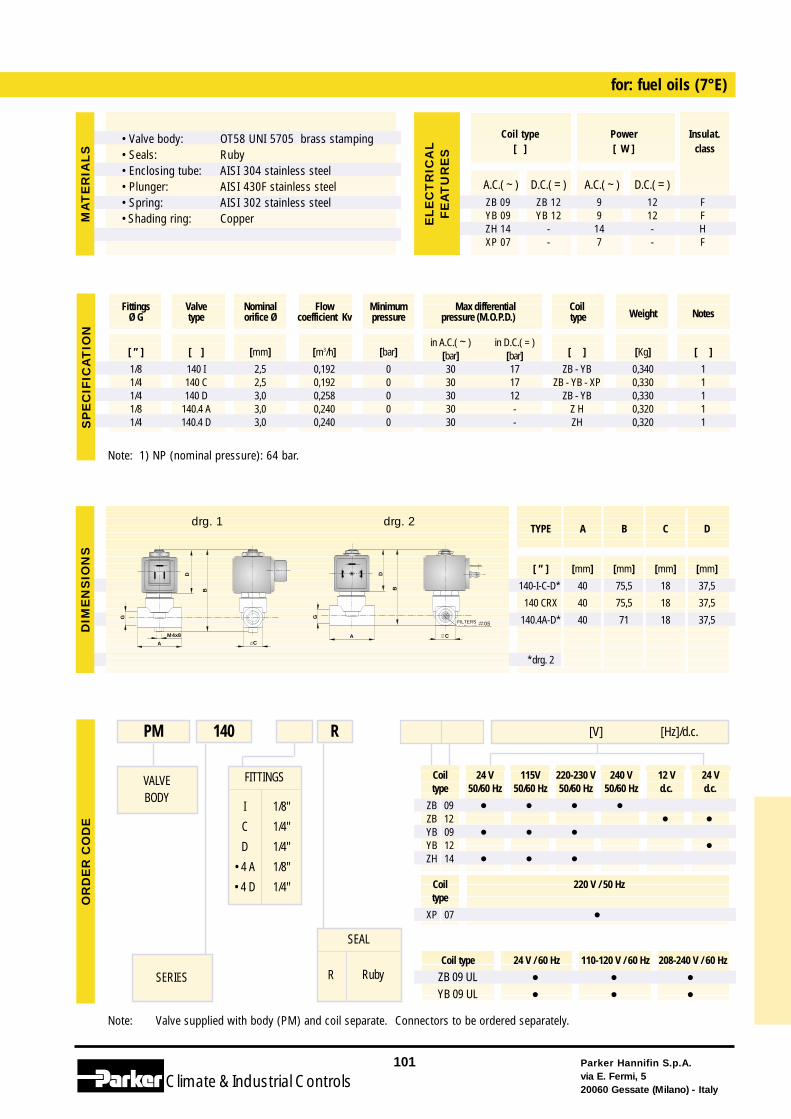
Coil 24 V 115V 220-230 V 240 V 12 V 24 Vtype 50/60 Hz 50/60 Hz 50/60 Hz 50/60 Hz d.c. d.c.
ZB 09 • • • •ZB 12 • •YB 09 • • •YB 12 •ZH 14 • • •
Coil type 24 V / 60 Hz 110-120 V / 60 Hz 208-240 V / 60 Hz
ZB 09 UL • • •YB 09 UL • • •
Note: Valve supplied with body (PM) and coil separate. Connectors to be ordered separately.
FITTINGS
I
C
D
• 4 A
• 4 D
1/8"
1/4"
1/4"
1/8"
1/4"
for: fuel oils (7°E)
VALVEBODY
SERIES
PM 140 [V] [Hz]/d.c.R
SEAL
R Ruby
Note: 1) NP (nominal pressure): 64 bar.
Parker Hannifin S.p.A.via E. Fermi, 520060 Gessate (Milano) - Italy
101
Climate& Industrial Controls
[ ” ] [ ] [mm] [m3/h] [bar]in A.C.( ~ ) in D.C.( = )
[ ] [Kg] [ ][bar] [bar]1/8 140 I 2,5 0,192 0 30 17 ZB - YB 0,340 11/4 140 C 2,5 0,192 0 30 17 ZB - YB - XP 0,330 11/4 140 D 3,0 0,258 0 30 12 ZB - YB 0,330 11/8 140.4 A 3,0 0,240 0 30 - Z H 0,320 11/4 140.4 D 3,0 0,240 0 30 - ZH 0,320 1
Fittings Valve Nominal Flow Minimum Max differential CoilWeight NotesØ G type orifice Ø coefficient Kv pressure pressure (M.O.P.D.) type
SP
EC
IFIC
AT
ION
OR
DE
RC
OD
E
A.C.( ~ ) D.C.( = ) A.C.( ~ ) D.C.( = )ZB 09 ZB 12 9 12 FYB 09 YB 12 9 12 FZH 14 - 14 - HXP 07 - 7 - F
Coil type Power Insulat.[ ] [ W ] class
EL
EC
TR
ICA
LF
EA
TU
RE
S
Coil 220 V / 50 Hztype
XP 07 •
MA
TE
RIA
LS
G
B
A C
D
M4x8
DIM
EN
SIO
NS
TYPE A B C D
[ ” ] [mm] [mm] [mm] [mm]
140-I-C-D* 40 75,5 18 37,5
140 CRX 40 75,5 18 37,5
140.4A-D* 40 71 18 37,5
*drg. 2
G
B
CA
D
FILTRO 0.5
drg. 1 drg. 2
• Valve body:• Seals:• Enclosing tube:• Plunger:• Spring:• Shading ring:
OT58 UNI 5705 brass stampingRubyAISI 304 stainless steelAISI 430F stainless steelAISI 302 stainless steelCopper
FILTERS
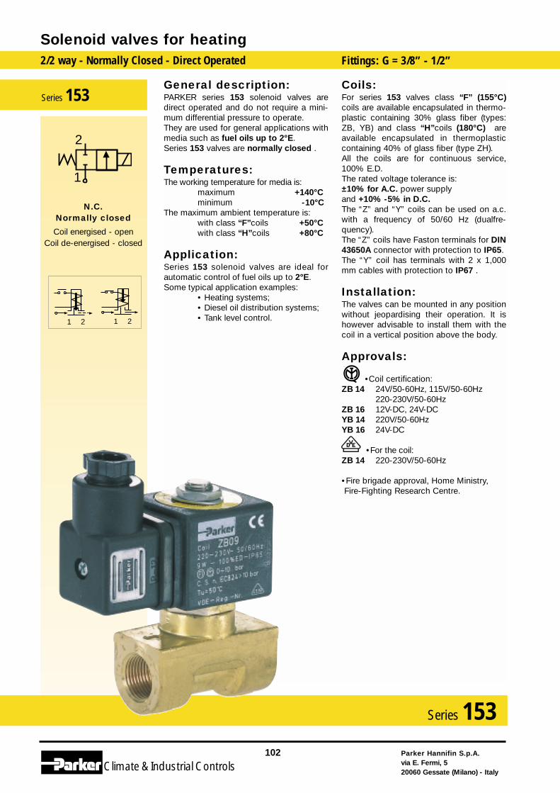
General description:PARKER series 153 solenoid valves aredirect operated and do not require a mini-mum differential pressure to operate. They are used for general applications withmedia such as fuel oils up to 2°E. Series 153 valves are normally closed .
Temperatures:The working temperature for media is:
maximum +140°Cminimum -10°C
The maximum ambient temperature is:with class “F”coils +50°Cwith class “H”coils +80°C
Application:Series 153 solenoid valves are ideal forautomatic control of fuel oils up to 2°E.Some typical application examples:
• Heating systems;• Diesel oil distribution systems;• Tank level control.
Coils:For series 153 valves class “F” (155°C)coils are available encapsulated in thermo-plastic containing 30% glass fiber (types:ZB, YB) and class “H”coils (180°C) areavailable encapsulated in thermoplasticcontaining 40% of glass fiber (type ZH).All the coils are for continuous service,100% E.D.The rated voltage tolerance is:±10% for A.C. power supplyand +10% -5% in D.C.The “Z” and “Y” coils can be used on a.c.with a frequency of 50/60 Hz (dualfre-quency).The “Z” coils have Faston terminals for DIN43650A connector with protection to IP65.The “Y” coil has terminals with 2 x 1,000mm cables with protection to IP67 .
Installation:The valves can be mounted in any positionwithout jeopardising their operation. It ishowever advisable to install them with thecoil in a vertical position above the body.
Approvals:
•Coil certification:ZB 14 24V/50-60Hz, 115V/50-60Hz
220-230V/50-60HzZB 16 12V-DC, 24V-DCYB 14 220V/50-60HzYB 16 24V-DC
•For the coil:ZB 14 220-230V/50-60Hz
•Fire brigade approval, Home Ministry, Fire-Fighting Research Centre.
Solenoid valves for heating2/2 way - Normally Closed - Direct Operated Fittings: G = 3/8” - 1/2”
Parker Hannifin S.p.A.via E. Fermi, 520060 Gessate (Milano) - Italy
102
Climate& Industrial Controls
Series 153
2121
2
1
N.C.Normally closed
Coil energised - openCoil de-energised - closed
Series 153
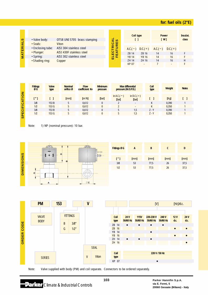
Coil 24 V 115V 220-230 V 240 V 12 V 24 Vtype 50/60 Hz 50/60 Hz 50/60 Hz 50/60 Hz d.c. d.c.
ZB 14 • • • •ZB 16 • •YB 14 •YB 16 • •ZH 14 • • •ZH 16 •
Note: Valve supplied with body (PM) and coil separate. Connectors to be ordered separately.
FITTINGS
B
G
3/8"
1/2"
for: fuel oils (2°E)
VALVEBODY
SERIES
PM 153 [V] [Hz]/d.c.V
SEAL
V Viton
Note: 1) NP (nominal pressure): 10 bar.
Parker Hannifin S.p.A.via E. Fermi, 520060 Gessate (Milano) - Italy
103
Climate& Industrial Controls
[ ” ] [ ] [mm] [m3/h] [bar]in A.C.( ~ ) in D.C.( = )
[ ] [Kg] [ ][bar] [bar]3/8 153 B 5 0,612 0 2 - K 0,390 11/2 153 G 5 0,612 0 2 - K 0,350 13/8 153 B 5 0,612 0 5 1,5 Z - Y 0,390 11/2 153 G 5 0,612 0 5 1,5 Z - Y 0,350 1
Fittings Valve Nominal Flow Minimum Max differential CoilWeight NotesØ G type orifice Ø coefficient Kv pressure pressure (M.O.P.D.) type
G
B
CA
D
SP
EC
IFIC
AT
ION
DIM
EN
SIO
NS
OR
DE
RC
OD
E
Fittings Ø G A B C D
[ ” ] [mm] [mm] [mm] [mm]
3/8 53 77,5 26 37,5
1/2 53 77,5 26 37,5
MA
TE
RIA
LS
A.C.( ~ ) D.C.( = ) A.C.( ~ ) D.C.( = )ZB 14 ZB 16 14 16 FYB 14 YB 16 14 16 FZH 14 ZH 16 14 16 HKP 07 - 7 - F
Coil type Power Insulat.[ ] [ W ] class
EL
EC
TR
ICA
LF
EA
TU
RE
S
Coil 220 V / 50 Hztype
KP 07 •
• Valve body:• Seals:• Enclosing tube:• Plunger:• Spring:• Shading ring:
OT58 UNI 5705 brass stampingVitonAISI 304 stainless steelAISI 430F stainless steelAISI 302 stainless steelCopper
Solenoid valves for heating
Parker Hannifin S.p.A.via E. Fermi, 520060 Gessate (Milano) - Italy
104
Climate& Industrial Controls
Total or partial reproduction of text, dra-wings or photographs is prohibited unlessexpressly authorised in writing by ParkerHannifin S.p.A.
The text, drawings and photographs con-tained in this catalogue are approximateand may be changed at any time, withoutnotice, as new technology appears.

Parker Hannifin S.p.A.Via E. Fermi, 520060 GESSATE (MI) ITALYTel.: + 39 - 02 - 95 125.1Fax: + 39 - 02 - 95 38 20 51
Cat.: GP / GB05/02 - 901002
ControlsClimate & Industrial