SOLENOID VALVE FOR VACUUM VA01series PDF/VA01 series.pdf · 2 4-port 3-position...
27
SOLENOID VALVE FOR VACUUM VA01 series
Transcript of SOLENOID VALVE FOR VACUUM VA01series PDF/VA01 series.pdf · 2 4-port 3-position...

SOLENOID VALVE FOR VACUUM
VA01series

1
Small-sized 3-port 2-position direct-acting solenoid valve for vacuum
VA01PSV23for vacuum
VA01PSP23for vacuum break (positive pressure)
●Compact and lightweightVery compact plastic body in 10 mm width,weighting only 25 g.
●Two types of vacuum control and vacuumbreak control availableTwo types of models for vacuum control and vacuumbreak contol (positive pressure:0.5 MPa max.) are available as VA01 Series.
●Minimized vacuum learkVacuum leak is reduced to less than 2 kPa /min (at-90 kPa, 20 cm3).
●Quick response time5 ms response time and stable action at the time ofturning on
●Mountable on manifoldCommon vacuum supply port or common positivepressure supply port manifolds are available.
●Usable for air blowSmall-sized directing-acting valve VA01PSV23 canbe used for air blow.
●Configurable with composite manifold(option)It is posible to configure a vacuum unit with a doublemanifold equipped with both solenoid valves forvacuum and vacuum break.
Most suitable for vacuum and vacuum break control !
Features 1
For Safety Use 6
Solenoid valves/Common Instructions 7
Solenoid Valves VA01 Series/Individual Instructions 10
Latching Solenoid Valves/Individual Instructions 11
3-port 2-position direct-acting solenoid valve for vacuum
VA01PSV23/VA01PSP23 12
4-port 3-position direct-acting solenoid valve for vacuum
VA01PEP34 15
3-port 3-position direct-acting solenoid valve for vacuum
VA01RDP33 19
3-port 2-position direct-acting solenoid valve for vacuum
VA01PLV23/VA01PLP23 23
CONTENTS
2
1 3
2
1 3
1:Vacuum supply port2:Output port3:Atmospheric release port
1:Pressure port2:Output port3:Exhaust port
VA01PSV23
VA01PSP23

2
VA01PEP344-port 3-position direct-actingsolenoid valve for vacuum
2 Y
3 1Solenoid A side
Solenoid B side
■Example where no atmospheric releasing mechanism is used↑
Atmospheric pressure
Vacuum
Sol
enoi
d va
lve
for
vacu
um b
reak
: O
N
Sol
enoi
d va
lve
for
vacu
um b
reak
: O
FF Time→
Blowing off by overshoot of breaking pressure
Breaking time varies.
Vacuum pressur varies.
■Example where no atmospheric releasing mechanism is used↑
Atmospheric pressure
Vacuum
Sol
enoi
d A
sid
e
O
FF
Sol
enoi
d B
sid
eO
N
Sol
enoi
d B
sid
eO
FF Time→
(Int
erm
edia
te p
ositi
on)
Vacuum pressur varies.
Reduces overshoot.
Reduces variation of breaking time by atmospheric release.
Atmospheric release
Pre
ssur
e
Pre
ssur
e
●Lightweight and compactBody width 10 mm, weight 56 g
●One unit works for both vacuum controland vacuum break controls.Vacuum control valve and vacuum break controlvalve (pressur:0.5MPa max.) are united.
●Quick response time5 ms response time and stable action at the timeof turning on/off.
●Throttle valve for vacuum break flowcontrolAir flow for vacuum break can be controlled accord-ing to work being attracted by setting a needle valve in the flow path for vacuum break.
●Atmospheric release mechanismIt serves to release the suction side pressure tothe atmospheric air once and then supply air forvacuum break, when doing vacuum break fromthe vacuum state. This feature will be highlyeffective for loading and unloading very smallwork quickly in a stable state.
●ManifoldingVacuum port for common or individual manifoldsare available, making it possible to manifold up to12 stations.
1:Positive pressure supply port2:Output port3:Vacuum supply portY:Atmospheric release port
To customers having thefollowing problemes inattracting very small work;●Parts around vacuum-breaking air are blown off, when work
is detached.●Timing of detaching work tends to vary.●Re-attraction occurs after work is detached.●Two solenoid valves are required to set up an atmospheric
release circuit.
Using VA01 PEP34 will cut down theseproblems.
Most suitable for attraction and conveyance of very small work !

3
VA01RDP333-port 3-position direct-actingsolenoid valve for vacuum
2
3 1
●Lightweight and compactBody width 10 mm, weight 45 g
●One unit works for both vacuum controland vacuum break controls.Vacuum control valve and vacuum break controlvalve (presure:0.2 MPa max.) are united.
●Holds vacuum at intermediate positionSolenoid valve returns to intermediate position at thetime of power failure and emergency stop, and holdsattraction with vacuum pad.
●Quick response time5 ms response time and stable action at the time ofturning on/off
●Throttle valve for vacuum break flowcontrolAir flow for vacuum break can be controlled accordingto work being attracted by setting a needle valve in theflow path for vacuum break.
●ManifoldingVacuum port for common or individual manifolds areavailable, making it possible to manifold up to 20stations.
●Manifold with throttle valve for vacuumflow controlVacuum flow can be controlled according to work bysetting a needle valve in the flow path to eachsolenoid valve in the manifold.
1:Positive pressure supply port2:Output port3:Vacuum supply port
Most suitable for attraction and conveyance in vacuum pump lines !
2 2 2 2
31
Throttle valve for vacuum break flow control
Throttle valve for vacuum flow control

4
Compact
Energy saving
Safety
Double solenoid has been downsized to single solenoid.
Energy-saving circuit is incorporated;power consumption during holding is 0.5W.No necessity for turning on power continuously to hold switching position.
Detent mechanism to hold switching position with permanent magnet assuressafety operations such as keeping attraction by vacuum.
Small-sized 3-port 2-position direct-acting latching solenoid valve for vacuum
VA01PLV23 for vacuum
VA01PLP23 for vacuum break (positive pressure)
2
1 3
1:Vacuum supply port2:Output port3:Atmospheric release port
VA01PLV232
1 3
1:Pressure port2:Output port3:Exhaust port
VA01PLP23
Newly developed one coil latch type solenoid is incorporated !
Powerful lineup of VA01 seriesIn addition to 2-position/3-position types and air releasing type, 3-port latch
type solenoid valve has joined in this series.
Full lineup of solenoid valves with 10mm body width for vacuum is available.
Minimized vacuum leakVacuum leak is reduced to 2kPa/min (at -90kPa, 20cm3)

5
FOR SAFETY USEBe sure to read the following instructions before use.
For common and individual instructions, refer to the text of this catalog.
The following safety precautions are provided to prevent damage and danger to personnel and to provideinstructions on the correct usage of this product. These precautions are classified into 3 categories;“CAUTION”,“WARNING”and“DANGER”according to the degree of possible injury or damage and thedegree of impendence of such injury or damage.Be sure to comply with all precautions along with JIS B8370(※1) and ISO 4414(※2), as they include importantcontent regarding safety.
(※1) JIS B8370 : General Rules for Pneumatic Systems(※2) ISO 4414 : Pneumatic fluid power-General rules relating to systems
CAUTION :Indicates a potentially hazardous situation which may arise due to improper handling oroperation and could result in personal injury or property-damage-only accidents.
WARNING:Indicates a potentially hazardous situation which may arise due to improper handling oroperation and could result in serious personal injury or death.
DANGER :Indicates an impending hazardous situation which may arise due to improper handling oroperation and could result in serious personal injury or death.
WARNING
●The applicability of vacuum equipment to the intended system should be judged by thepneumatic system designer or the personnel who determined specifications for such system.As operating conditions for products contained in this catalog are diversified, the applicability of vacuum equipment to the
intended system should be determined by the pneumatic system designer or the personnel who determined
specifications for such system after conducting an analysis or testing as necessary.
The system designer shall be responsible for assuring the intended system performance and safety.
Before making a system, the system designer should thoroughly examine all specifications for such a system and also take
into consideration the possibility of any trouble with the equipment.
●The vacuum equipment should be handled by persons who have sufficient knowledge and richexperience.Inproper handling of compressed air and vacuum will result in danger.Assembling, operation and maintenance of machinery using vacuum equipment should be performed by persons who have
sufficient knowledge and rich experience.
●Never operate machinery nor remove the equipment until safety is assured.
・Befor cheking or servicing machinery and equipment, be sure to check that steps for prevention of dropping or
runaway of the driven component have been completely taken.
・When removing the equipment, make sure that the above-mentioned safety measures have been done beforehand.
Then turn off air supply and power to the system and purge compressed air in the system.
・When restarting machinery and equipment, check that proper prevention of malfunction has been provided for and then
restart carefully.
●When using the vacuum equipment in the following conditions or environments, take theproper safety measures and consult KURODA beforehand.・Conditions and environments other than specified and outdoor use.
・Applications to nuclear power equipment, railroads, aircraft, vehicles, medical equipment, equipment connected with
food and drink, amusement facilities and safety devices such as emergency interruption devices, clutch/brake circuits
for a press and the likes.
・Applications which require extreme safety and will also greatly affect men and property.

6
SOLENOID VALVES FOR VACUUM/COMMON INSTRUCTIONS ①Be sure to read them before use.Also refer to Par. "For Safety Use" and instructions mentioned for each series of solenoid valves.
DESIGN DESIGN
SELECTION
WARNING CAUTION
WARNING
Power failure and trouble of air supply will lead tovacuum down ; this sometimes results in an accident.
Take a safety measure against such and accident.
If vacuum pad loses its sucking force due to vacuum down, the
workpiece being carried will drop, endangering the human body and
machine, Provide prevention against the drop of a workpiece or take
a proper safety measure.
Do not use for emergency shutoff valves.
Solenoid valves listed in this catalogue are not designed for use in
emergency shutoff valves and other safety applications.
When using the solenoid valve for such applications, provide an
independent means to assure safety.
Exhausting residual air
Provide a residual air exhausting function in due consideration of
maintenance and inspection.
Use in vacuum
In order to prevent sucking foreign matters from the suction pad and
exhaust port, provide an inline filter, air muffler between the
suction pad and solenoid valve and at the exhaust port.
Applying current continuously for long time
When using a solenoid valve while applying current to it
continuously for a long period of time, contack KURODA
beforehand.
Remodeling the solenoid valve
Do not remodel the solenoid valve.
¡
¡
¡
¡
¡
¡ Use at low temperature
When using a solenoid valve at 5℃ or below, provide an air
dryer or other proper means to prevent moisture from solidifying or
freezing.
Shock and vibration
Reduce shocks and vibrations applied to the solenoid valve to
less than the prescribed value. (refer to specifications.)
Applying shocks and vibrations exceeding the prescribed value may
rsult in a malfunction of the solenoid valve.
¡
¡
Check the specifications.
Solenoid valves listed in this catalog are designed for vacuum or
compressed air. Avoid using other fluid than vacuum or
compressed air. Do not use a solenoid valve at any pressure
and temperature outside the range of specifications, otherwise
resulting in a breakdown or malfunction.
¡
CAUTIONLeak current
When a C-R element is used in the contack protective circuit
(surge voltage protection), leak current will flow through the C-R
element.
If this leak current becomes large, a malfunction will occur.
Therefore, reduce leak current to less than 1 mA.
¡
C-R circuit
Leak current
Power supply
Solenoid
Contact

7
SOLENOID VALVES FOR VACUUM/COMMON INSTRUCTIONS ②Be sure to read them before use.Also refer to Par. "For Safety Use" and instructions mentioned for each series of solenoid valves.
MOUNTING
WARNINGWhen mounting the solenoid valve, firmly fix it whileusing care to prevent the stationary part and joint fromloosening.
If the solenoid valve is mounted with insufficient strength, it may
sometimes come off.
Do not start the system until it is ensured that equipmentworks properly.
After mounting the solenoid valve, connect power supply and
then perform a functional test and a leak test. Check that it has
been correctly mounted and works properly, before starting the
system.
Coating with paint
When coating the resin portion with paint, it may be adversely
affected by paint and solvent. For the propriety of painting,
contack KURODA beforehand.
Do not peel off the nameplate affxed on the solenoid valve and do
not erase or smear out the letter on it.
Provide space for maintenance and inspection.¡
¡
¡
¡
Do not wipe off the model name inscribed on a name-plate etc, with organic solvent.
The inscribed indication may be erased.
Tightening torque for mounting screw
Recommended tightening torque range is shown as below.
Fit an air muffler to the exhaust port of the solenoidvalve.
Dust or foreign matter that enters it may cause a malfunction of the
solenoid valve.
¡
¡
¡
How to apply liquid sealant
When applying liquid sealant to the threaded portion, apply a
proper mount to about 1/3 of the periphery of the threaded
portion and then screw it.
¡
Avoid wrong piping.
When connecting a pipe to each equipment, be careful not to
mistake the supply port etc. by referring to the nameplate afixed to
the product or the product catalog.
¡
CAUTION
PIPING
CAUTIONAvoid spiral pipe laying.
When spiral pipe laying is used in a vacuum line, it may
sometimes delay attaining vacuum due to the resistance of
piping or cause vacuum down at the suction end ; resulting in the
malfunction of the vacuum sensor.
For manifold type solenoid valve, pay attention topiping diameter.
When increasing the number of manifolded units, flow may be
insufficient according to circumstances. In this case, supply and
exhaust from both sides of the manifold.
Before piping
Thoroughly flush the inside of each pipe to remove chips,
coolant, dust, etc. before piping.
How to wind a seal tape
When winding a seal tape around the threaded portion, leave
space of 1.5 to 2 thread turns.
¡
¡
¡
¡
1/3
Apply sealant tothis portion.
Joint Sealant
(Good) (No good)
Leave space of 1.5 to 2 tums.
When screwing seal ortape enters equipment,causing air leak.
Valve No.
VA01PSV23
VA01PSP23
VA01PEP34
VA01RDP33
VA01PLV23
VA01PLP23
Screw size
M1.7
M1.7
M1.7
M1.7
Tightening torque(N・m)
0.10~0.14
0.12~0.20
0.12~0.20
0.10~0.14

8
SOLENOID VALVES FOR VACUUM/COMMON INSTRUCTIONS ③Be sure to read them before use.Also refer to Par. "For Safety Use" and instructions mentioned for each series of solenoid valves.
WIRINGPIPING
CAUTION WARNINGScrew of pipe and joint
When screwing the pipe and joint, use care to prevent chips and
sealant from entering the pipe and joint.
Tighten them within a proper range of tightening torque.
¡
APPLICABLE TUBES
CAUTIONUsed nylon tubes or polyurethane tubes made byKURODA for Instant Joints. When using tubes made byother companies, check the diametral accuracy.
There are some commercially available tubes that do not satisfy the
specified diametral accuracy.
Do not extremely bend the tube near the joint ; otherwiseresulting in the break or bucking of the tube.
When using the tube with it bent, use at more than minimum
bend radius.
When using with other fluid than air, consult KURODA.¡
¡
¡
CONNECTION AND DISCONNECTION OF TUBE
CAUTIONHow to connect a tube
When using a tube, cut it at right angles axially with the special
tool (Tube Cutter/TC-16). Cutting it with scissors or nippers to
cause a deformation may result in air leak or coming off.Fully insert the tube up to the tube end.
Pull the tube lightly and check that it does not come off from the
joint.
How to disconnect a tubePull out the tube while pushing the release ring in paralle. Before
pulling out the tube, be sure to discharge residual pressure.When reusing the disconnected tube, cut off the bitten portion of
the tube.
¡
¡
¡
¡
¡
When doing wiring work, be sure to turn off compressedair, vacuum and power supplies beforehand.
Wiring work without turning off air, vacuum and power supplies may
cause an electric shock or malfunction, this sometimes results in an
injury to the human body or a domage to property.
Avoid mis-wiring.
Some solenoid valves have polarity : Those operating on DC
with built-in indicator light and those equipped with surge
protective circuit.
When wiring to a solenoid valve, check whether or not it has
polarity.
For a solenoid valve having polarity, check the lead wire color
and symbol of the polarity by the catalog or actual article
beforehand and then make correct wiring.
Avoid applying stress and tensile force to lead wirerepeatedly.
Wiring made in such a manner that stress and tensile force are
repeatedly applied to the lead wire will result in the breaking of wire.
Provide some degree of margin for wiring.
Check that there is no insulation failure.
If an insulation failure occurs in the lead wire connection,
extension cable and terminal base, an excess flows to the
switching element of the solenoid valve or control unit,
sometimes resulting in a damage.
Do not mistake applied voltage.
Mistake in applied voltage in case of wiring to a solenoid valve will
cause an operation failure or burn out the coil.
After completion of wiring, check for wrong connectionbefore turning on power.
Do not supply power at the same time.
Do not supply power to both double solenoid type valve and
latch type solenoid valve at the same time.
¡
¡
¡
¡
¡
¡
¡
Port size
M3
M5
R、Rc 1/8
R、Rc 1/4
Tightening torque(N・m)
0.3~0.5
1.5~2.0
7.0~9.0
12~14

9
SOLENOID VALVES FOR VACUUM/COMMON INSTRUCTIONS ④Be sure to read them before use.Also refer to Par. "For Safety Use" and instructions mentioned for each series of solenoid valves.
MAINTENANCE AND INSPECTIONOPERATING ENVIRONMENTS
DANGER WARNINGDo not use solenoid valve in a explosive environment.¡
WARNINGDo not use a solenoid valve in atmospheres containingcorrosive gases, chemicals, seawater, water and vaporand in places where a solenoid valve contacts thesematters.Do not use a solenoid valve in a place where vibrationsor shocks are directly applied to it.When a solenoid valve is exposed to the direct sunlight,fit a protective cover to the solenoid valve.When a solenoid valve is located around a heat source,shut off the radiant heat.When installing a solenoid valve in the control panel,take proper heat-radiating measures so that the insidetemperature may be kept within the specified temper-ature range.When using a solenoid valve in a place where it isexposed to welding spatters, provide a protectivecover or other proper prevention.
Welding spaters may burn out the plastic parts of the solenoid valve,
sometimes resulting in a fire.
¡
¡
¡
¡
¡
¡
Inspection before maintenance
First check that load drop prevention has been provided.
Then shut off air and power supplies to the system and exhaust
residual air in the system beforehand.
Inspection after maintenance
When restarting the system, check that preventive measures
against flying-out of the actuator have been taken. Then connect
compressed air supply to the pneumatic system, and perform a
proper functional test and a leak test to check that it works
safely without fail, before starting the system.
Operation at low frequency
To prevent an operation failure, perform the switching action of the
solenoid valve once per 30 days. (Be careful of air supply.)
Manual operation
When the solenoid valve is manually operated, the system
connected to it is also operated. Make sure safety before
operation.
Disassembly of solenoid valve
When disassembling the solenoid valve, contact KURODA
beforehand.
¡
¡
¡
¡
¡
CAUTIONDraining
To keep the quality of air to a certain level, drain the air filter at
periodical intervals.
Chek and clean the vacuum filter and silencer every-day, and also change the element periodically.
Silting will deteriorate the performance.
¡
¡
QUALITY OF AIR
WARNINGUse pure air.
Compressed air containing corrosive gases, chemicals, salt, etc.
causes a breakdown or operation failure. So do not use such air.
¡
CAUTIONFit an air filter with filtration of 5μm or fine.
Install an air dryer.
Compressed air containing much drainage causes the operation
failure of pneumatic equipment. lnstall and air dryer, lower the
temperature and reduce drainage.
Take proper countermeasures against sludge.
If sludge produced in compressor oil enters pneumatic equipment, it
will cause the operation failuse of pneumatic equipment. it is
recommendable to use compressor oil (NISSEKI FAIRCALL A68,
IDEMITSU DAPHUNY SUPER CS68) featuring minimized sludge
production or use a coalescing filter to prevent sludge from
entering the pneumatic equipment.
¡
¡
¡
Filter Coalescing filter Regulator

10
SOLENOID VALVES VA01 SERIES/INDIVIDUAL INSTRUCTIONSBe sure to read them before use.Also refer to Par. "For Safety Use" and common instructions.
WIRING SPECIFICATIONS
INTERNAL CIRCUIT OF P & U TYPEVA01PSP23/VA01PSV23/VA01RDP33
VA01PEP34
HOW TO USE CONNECTORS
CAUTIONHow to attach and detach a connector
When attaching a connector, pinch the clip with your finger and
insert the connector into the pin straight to the end.
When detaching a connector, pinch the clip with your finger and pull
out the connector straight.
¡
Sol
enoi
d
Red
Black
Black
Red
L typeLead wire (AWG26 length 300 mm)
¡
P type
Connector with lead wire (AWG26 length 500 mm), side outlet
(with indicator light & surge suppressor)
¡
U type
Connector with lead wire (AWG26 length 500 mm), upside outlet
(with indicator light & surge suppressor)
¡
Solenoid vallve
Polarity mark
Pin
Connector
Lever
CONTINUOUS SUPPLY OF POWER
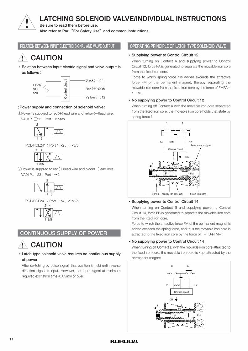
CAUTIONLatch type solenoid valve requires no continuous supply
of power.
After switching by pulse signal, that position is held until reverse
direction signal is input. However, set input signal at minimum
required excitation time (0.05ms) or over.
¡
〈Power supply and connection of solenoid valve〉
①Power is supplied to red(+)lead wire and yellow(-)lead wire.
VA01PL□23:Port 1 closes
②Power is supplied to red(+)lead wire and black(-)lead wire.
VA01PL□23:Port 1→2
PCL/RCL241:Port 1→2、4→3/5
PCL/RCL241:Port 1→4、2→3/5
Supplying power to Control Circuit 12
When turning on Contact A and supplying power to Control
Circuit 12, force FA is generated to separate the movable iron core
from the fixed iron core.
Force to which spring force f is added exceeds the attractive
force FM of the permanent magnet, thereby separating the
movable iron core from the fixed iron core by the force of F=FA+
f-FM.
No supplying power to Control Circuit 12
When turning off Contact A with the movable iron core separated
from the fixed iron core, the movable iron core holds that state by
spring force f.
¡
¡
Supplying power to Control Circuit 14
When turning on Contact B and supplying power to Control
Circuit 14, force FB is generated to separate the movable iron core
from the fixed iron core.
Force to which the attractive force FM of the permanent magnet is
added exceeds the spring force, and thus the movable iron core is
attracted to the fixed iron core by the force of F=FB+FM-f.
No supplying power to Control Circuit 14
When turning off Contact B with the movable iron core attracted to
the fixed iron core, the movable iron core is kept attracted by the
permanent magnet.
¡
¡
Latch SOL coil
Control circuit Black(-)14
Red(+)COM
Yellow(-)12
2
1 3
2
1 3
2 4
1 3/5
2 4
1 3/5
Permanent magnetControl circuit
B A
12COM
CA
14
FA
Coil Fixed iron coreMovable iron coreSpring
FMF
f
Control circuit
AB
14 COM
CB
12
FB
F FM
f
11
LATCHING SOLENOID VALVE/INDIVIDUAL INSTRUCTIONSBe sure to read them before use.
Also refer to Par.“For Safety Use”and common instructions.
OPERATING PRINCIPLE OF LATCH TYPE SOLENOID VALVERELATION BETWEEN INPUT ELECTRIC SIGNAL AND VALVE OUTPUT
CAUTIONRelation between input electric signal and valve output isas follows:
¡

12
Small-sized 3-port 2-position direct-acting solenoid valve for vacuum
VA01PSV23 for vacuum
VA01PSP23 for vacuum break (positive pressure)
SpecificationsModel No.
Fluid
Port size
Unit
r/min(ANR)
r/min(ANR)
℃
ms
ms
V
%
W
m/s2
g
VA01PSV23
Air
22(at -100kPa)
-
-100~0kPa
-
40(at 0.5MPa)
0~0.5MPa
M5
-10~50
5 or less
5 (10) or less
DC24
±10
Grade B
2
Lead wire, connector with lead wire
150/50
25
VA01PSP23
Air
Pressure range
Ambient temperature
Rated voltage
Permissible voltage fluctuation
Heat resistance grade
Power consumption
Wiring
Vibration resistance/Shock resistance
Mass
Flow
Responsetime
Vacuum
Vacuum break
(Note)・When using the valve for vacuum break at less than 5 ℃ by supplyingcompressed air, use dry air passing through an air dryer to prevent dewcondensation and freezing.
・Response time in bracket ( ) shows with surge suppressor.
Ordering instruction
PS V23
①
1 L- - M5 -
② ③ ④ ⑤ ⑥
①Type of piping
Solenoid valve
VA01 V3 CC- V01 - M5
② ③ ④①
Manifold
Connector with lead wire
MFS
PSSub-base pipingSingle solenoid
①Number of stations2:
20
2 stations:
20 stations
⑤Port sizeNo mark No sub-base
M5 M5×0.5
③Voltage1 DC24V
②Function
V23
P23
2-position 3-portVacuum
2-position 3-portVacuum break (Positive pressure)
④Wiring specficationsL
P
U
Lead wireConnector with lead wire, Side outlet(With indicator light & surge suppressor)
Connector with lead wire, Upside outlet(With indicator light & surge suppressor)
⑥Wiring accessoriesNo mark No connector
EConnector with lead wire(Length : 500 mm)
②Type of valveV3 PSV23 for vacuum
PSP23 for positive prssureP3
CAUTION ・Supply prssure of -100 to 0 kPa to vacuum supply port of VA01PSV23. Do not supply positive pressure.・Supply pressur of 0 to 0.5 MPa to positive pressure supply port of VA01PSP23. Do not supply vacuum pressure.
③Manifold specificationsCC Common 1, Common 3
④Port sizeM5 M5×0.5
ON
OFF
(Note) Model without sub-base is provided withmounting screw and base gasket.
Lead wire length0500mm1000mm
Model No.PC2-D24-CL5(Standard)PC2-D24-CL10

13
Small-sized 3-port 2-position direct-acting solenoid valve for vacuum
49.9
4.6
Port 2M5×0.8Output port
5.4
5.5
12.5
14.5
Manual override
2.5 1520
2-φ2.5(Mounting hole)
41.9
12.6
Lead wire length 300AWG26
30.5
10
5.4
Port 1 M5×0.8Vacuum port/Pressure port
Port 3M5×0.8Atmospheric release port/Exhaust port
4.7
5.4
2
1 3
2
1 3
1:Vacuum supply port2:Output port3:Atmospheric release port
1:Pressure port2:Output port3:Exhaust port
VA01PSV23
VA01PSP23
49.4 6Lead wire length 500
AWG26
36.3
Lead wire length 500AWG26
L type
P type U type
638
.3
DimensionsSolenoid valve (Unit:mm)
VA01PS□23

14
Small-sized 3-port 2-position direct-acting solenoid valve for vacuum
Port 1M5×0.8Vacuum port/Pressure port
7
5.5
15
35.5
Lead wire length 300AWG26
Blank plateV23-BP
44.6 32
.99
11.8
2-φ3.5 (Mounting hole)
4 B
A
(4)
19.5
23.5
Port 3M5×0.8Atmospheric release port/Exhaust port
5.5
17.5
10
12.5 10.5
Lead wire length 500AWG26
640
.4
52.1
9
41.3
43.3 6
32.9
44.6
9
31
No.1 2 n
2 2 2 2
Circuit diagram
L type
P type U type
Lead wire length 500AWG26
Port 2n-M5×0.8
Output port
DimensionsManifold (Unit:mm)
MFS□-V01□3CC-M5
n
2345678910
A
35.54656.56777.58898.5
109119.5
B
27.53848.55969.58090.5
101111.5
n11121314151617181920
A130140.5151161.5172182.5193203.5214224.5
B122132.5143153.5164174.5185195.5206216.5
n : Number of stations

15
4-port 3-position direct-acting solenoid valve for vacuum
VA01PEP34Poppet seal/Sub-base piping type
SpecificationsModel No.FluidPort size
Unit
R /min(ANR)
R /min(ANR)
℃
ms
V
%
W
m/s2
g
VA01PEP34
Air
M5
20 at -100kPa(Port 3→2)
14 at 0.5MPa(Port 1→2)
-100~-30kPa 0.05~0.5MPa-10~50
ON : 5 or less OFF : 5 or less
DC24
±10
Grade B
0.9 (Holding), 4 (Inrush)
Lead wire, connector with lead wire
150/50
56
Pressure rangeAmbient temperatureResponse timeRated voltagePermissible voltage fluctuationHeat resistance gradePower consumptionWiringVibration resistance/Shock resistanceMass
FlowVacuumVacuum break
(Note)・When using the valve for vacuum break at less than 5 ? by supply ingcompressed air, use dry air passing through an air dryer to prevent dewcondensation and freezing.
Ordering instruction
P EP3
①
1 U-4 - M5 -
② ③ ④ ⑤ ⑥
-
⑦
①Type of piping
Solenoid valve
VA01 CC- V01P4 - M5
② ③①
Manifold
MFS
P Sub-base piping①Number of stations
2:
12
2 stations:
12 stations
⑤Port size
No mark No sub-baseM5 M5×0.8
③Voltage1 DC24V
②Function
EP3 3-position with atmospheric releasemechanism Double solenoid
④Wiring specfications
U Connector with lead wire, Upside outlet(With indicator light & surge suppressor)
⑥Wiring accessoriesNo mark No connector
E Connector with lead wire(Length:500 mm)
②Manifold specificationsCC Common 1 (Positive prssure), Common 3 (Vacuum)CI Common 1 (Positive prssure), Individual 3 (Vacuum)
(Note) Model without sub-base is provided with mounting screw and base gasket.
CAUTION ・Use positive pressure supply port within pressure range of 0 to 0.5 MPa. Do not supply vacuum pressure.・Use vacuum supply port within pressure range of -100 to 0 kPa. Do not supply positive pressure.
③Port sizeM5 M5×0.8
⑦OptionNo mark No option
F Atmosheric release port with filter
Connector with lead wireLead wire length
0500mm1000mm
Model No.PC2-D24-CL5(Standard)PC2-D24-CL10

16
4-port 3-position direct-acting solenoid valve for vacuum
Port 1M5×0.8Positive pressure supply port
Lead wire length 500
AWG26
Port 3M5×0.8Vacuum supply port
74
37
4 16
24
2.5
6.5
15 18
10
2.8
Atmospheric release port
2-φ3.5(Mounting hole)
Manual override (Vacuum side)
Port 2M5×0.8Output port
12
36.2
7 11
38.5
6
Throttle valve for vacuum break flow control
Manual override (Positive pressure side)
3.5
37
6
7
12
2
3 1
Y
1:Positive pressure supply port2:Output port3:Vacuum supply portY:Atmospheric release port
Atmospheric release portwith fiter
Atmospheric release port with filter
DimensionsSolenoid valve (Unit:mm)

17
4-port 3-position direct-acting solenoid valve for vacuum
Port 32-M5×0.8Vacuum supply port
(Opposit side plugged)
Throttle valve for vacuum break flow control
8
3.5
37
2.8
3.5
25
10.7
9.5
37
(3.5)
(3)
Atmospheric release port
2-φ3.5(Mounting hole)
Port 2n-M5×0.8Output port
A
B
16
5.5
15
42.5 6
5.5 1.5
14.5 10.5
Lead wire length 500AWG26
MAX41MIN38.5
3
2 2 2 2
131
Circuit diagram
Blank plateV34-BP
165.
5
8
17
Port 12-M5×0.8 Positive pressure supply port
(Opposit side plugged)
DimensionsManifold
MFS□-V01P4CC-M5
(Unit:mm)
n23456789
101112
A39.55060.57181.592
102.5113123.5134144.5
B32.54353.56474.58595.5
106116.5127137.5
n : Number of stations

18
4-port 3-position direct-acting solenoid valve for vacuum
Port 3n-M5×0.8Vacuum supply port
MAX41MIN38.5
Throttle valve for vacuum break flow control
Lead wire length 500
AWG26
8
15
42.5 6
16
14.5
A
B3.5
3710
.79.
5
2.8
3.5
25
37
(3.5)
(3)
Atmospheric release port
Port 2n-M5×0.8Output port
10.5
1.5
14.5
5.5
2-φ3.5(Mounting hole)
7.5
10.5
3
2 2 2 2
1 1
3 3 3
Circuit diagram
Blank plateV34-BP
16
8
17
Port 12-M5×0.8Positive pressure supply port(Opposit side plugged)
DimensionsManifold
MFS□-V01P4CI-M5
(Unit:mm)
n23456789101112
A39.55060.57181.592
102.5113123.5134144.5
B32.54353.56474.58595.5
106116.5127137.5
n : Number of stations

19
3-port 3-position direct-acting solenoid valve for vacuum
VA01RDP33Poppet seal/In-line piping type
SpecificationsModel No.
Fluid
Port size
Unit
R/min(ANR)
R/min(ANR)
℃
ms
V
%
W
W
m/s2
g
VA01RDP33
Air
M5
10 at-90kPa (Port 3→2)
8 at 0.2MPa (Port 1→2)
-100kPa~0.2MPa
-10~50
ON : 5 or less OFF : 5 (20) or less
DC24
±10
Grade B
0.5
0.55
Lead wire, connector with lead wire
150/50
45
Pressure range
Ambient temperature
Response time
Rated voltage
Permissible voltage fluctuation
Heat resistance grade
FlowVacuum
Vacuum break
L type
P, U typePowerconsumption
Wiring
Vibration resistance/Shock resistance
Mass
(Note)・When using the valve for vacuum break at less than 5 ℃ by supplyingcompressed air, use dry air passing through an air dryer to prevent dewcondensation and freezing.
・Response time in bracket ( ) shows with surge suppressor.Ordering instruction
R DP3
①
1 L-3 - M5 - -
② ③ ④ ⑤ ⑥ ⑦
①Type of piping
Solenoid valve
VA01 CC V- V01R35 - M5
② ③ ④①
Manifold
MFU
R In-line piping①Number of stations
2:
20
2 stations:
20 stations
⑤Port size
M5 M5×0.8④Port size
M5 M5×0.8
③Voltage
1 DC24V
④Wiring specfications
PConnector with lead wire, Side outlet(With indicator light & surge suppressor)
U Connector with lead wire, Upside outlet(With indicator light & surge suppressor)
L Lead wire
②Function
DP33-position closed centerDouble solenoid
⑦For mounting manifold
MFFor mounting manifold(With mounting screw, gasket)
⑥Wiring accessoriesNo mark No connector
EConnector with lead wire(Length : 500 mm)
③Throttle valve for vacuum flow controlNo mark No throttle valve
VThrottle valve for vacuum flow control(Only for CC specfication)
②Manifold specificationsCC Common 1 (Positive prssure), Common 3 (Vacuum)CI Common 1 (Positive prssure), Individual 3 (Vacuum)
(Note) No mark:Othersolenoid valvesthan those formounting manifold
(Note) Solenoid valve with thrott le valve forvacuum flow control is to be made to order.
CAUTION ・Use positive pressure supply port within pressure range of 0 to 0.2 MPa. Do not supply vacuum pressure.・Use vacuum supply port within pressure range of -100 to 0 kPa. Do not supply positive pressure.
Connector with lead eire
Lead wire length0500mm1000mm
Model No.PC2-D24-CL5(Standard)PC2-D24-CL10

20
3-port 3-position direct-acting solenoid valve for vacuum
Port 2 M5×0.8 Output port
7.4
19.4
3 5.5
3
2‐φ1.8(Mounting hole)
Manual override (Vacuum side)
2
3 1
1:Positive pressure supply port2:Output port3:Vacuum supply port
25.2
2.5
9.5
74
37 1.5
Throttle valve for vacuum break flow control
2-φ2.2(Mounting hole)
Lead wire length 300AWG26
20.3
L type
P type
U type
10
Port 3M5×0.8Vacuum supply port
Port 1M5×0.8 Positive pressure supply port
6.5 6.5
6 6
27.8
6
27.8
6
89
25.8
74
Lead wire length 500AWG26
Manual override (Positive pressure side)
Lead wire length 500AWG26
DimensionsSolenoid valve (Unit:mm)

21
3-port 3-position direct-acting solenoid valve for vacuum
MFU□-V01R3CC-M5
MFU□-V01R3CCV-M5(Order made)
MAX 41MIN 38.5
10.5
Port 3Rc!/8Vacuum supply port
7.5
15
35.3
Throttle valve for vacuum break flow control
Lead wire length 300AWG26
8.5
4034
15
A
B
17.5 10.5
(5.5)
3.5
2562.
5
Blank plateV33-BP
Port 2n-M5×0.8Output port
3
2 2 2 2
1
Circuit diagram
3
2 2 2 2
1
Circuit diagram
18.5
7.5
Throttle valve for vacuum flow control
MA
X8.
4M
IN 5
.510
.5
Port 3Rc!/8Vacuum supply port
MAX 41MIN 38.5
7.5
15
35.3
Throttle valve for vacuum break flow control
Lead wire length 500AWG26
7.5
17.5 10.5
8.5A B
4034
15
17.5 10.5
(5.5)
2-φ3.5(Mounting hole)
3.5
6 25
2.5
Port 2n-M5×0.8Output port
Port 1Rc!/8Positive pressure supply port
18.5
7.5
74
17
2-φ3.5(Mounting hole) Port 1
Rc!/8Positive pressure supply port
L type
L type
DimensionsManifold (Unit:mm)

22
3-port 3-position direct-acting solenoid valve for vacuum
MAX41MIN38.5
15
35.3
40.8
(Overall height)
42.8 6
(Overall height)
(Ove
rall
leng
th)
Lead wire length 500
AWG26
Lead wire length 500
AWG26
Port 3n-M5×0.8Vacuum supply port
17.5
A
B (5.5)
(Mounting hole)
Port 2n-M5×0.8Output port
17.5 10.5
Port 1Rc!/8Positive pressure supply port
2-φ3.5
7.5
8.5
7.5
74
15
3.5 6
2.5
18.5
25
4034
89
(ove
rall
leng
th)
74
6
10.5
3 2 3 2 3 2 2
1
3
Throttle valve for vacuum break flow control
Lead wire length 300AWG26
L type
P type
U type
17
Blank plateV33-BP
DimensionsManifold
MFU□-V01R3CI-M5
(Unit:mm)
Circuit diagram
n
2345678910
A
42.55363.57484.595
105.5116126.5
B
28.53949.56070.58191.5
102112.5
n11121314151617181920
A137147.5158168.5179189.5200210.5221231.5
B123133.5144154.5165175.5186196.5207217.5
n : Number of stations

23
Small-sized 3-port 2-position direct-acting latching solenoid valve for vacuum
VA01PLV23 for vacuum
VA01PLP23 for vacuum break (positive pressure)
SpecificationsModel No.
Fluid
Port size
Unit
R/min(ANR)
R/min(ANR)
℃
ms
V
%
W
g
VA01PLV23
Air
M5
22(at -100kPa)
-
-100~0kPa
-
40(at 0.5MPa)
0~0.5MPa
-5~50
3
DC24
±10
Grade B
Holding:0.5(Inrush:2)
Connector with lead wire
30
VA01PLP23
Air
M5
Pressure range
Ambient temperature
Response time
Rated voltage
Permissible voltage fluctuation
Heat resistance grade
Power consumption
Wiring
Mass
FlowVacuum
Vacuum break
(Note)When using the valve for vacuum break at less than 5˚C by supplyingcompressed air, use dry air passing through an air dryer to prevent dewcondensation and freezing.
Ordering instruction
V23 1 P- - M5 -
① ② ③ ④ ⑤
Solenoid valve
VA01PL V3 CC- V01 - M5
② ③ ④①
Manifold
Connector with lead wire
MFS
①Number of stations2:10
2 stations:
10 stations
②Type of valveV3 PLV23 for vacuum
PLP23 for positive prssureP3
CAUTION ・Supply prssure of -100 to 0 kPa to vacuum supply port of VA01PLV23. Do not supply positive pressure.・Supply pressur of 0 to 0.5 MPa to positive pressure supply port of VA01PLP23. Do not supply vacuum pressure.
③Manifold specificationsCC Common 1, Common 3
④Port sizeM5 M5×0.8
Lead wire length0500mm1000mm
Model No.PC2-D24-CL5(standard)PC2-D24-CL10
V232-position 3-portVacuum
①Function
P232-position 3-portVacuum break (Positive pressure)
④Port size
1 DC24V
②Voltage
PConnector with lead wire, Side outlet(With indicator light & surge suppressor)
③Wiring specifications
UConnector with lead wire, Upside outlet(With indicator light & surge suppressor)
No mark
M5
Without sub-base
M5×0.8
⑤Wiring accessoriesNo mark Without connector
EConnector with lead wire(Length:500 mm)
(Note) Model without sub-base is provided withmounting screw and base gasket.

P type
U type
Port 2M5×0.8
Manual override 12
2-φ2.52.5 1520
54.4
Port 1M5×0.8
12.6
16.9
14.9
5.4
27.9
1010
5.4
22.2
5
10 12.5
14.5
(Mounting hole)
Lead wire length 500
Lead wire length 500
49.4AWG26
Port 3M5×0.8
AWG26
4.7
Manual override 14
4.6
5.4
2
1 3
1:Vacuum supply port2:Output port3:Atmospheric release port
VA01PLV23
2
1 3
1:Pressure port2:Output port3:Exhaust port
VA01PLP23
24
Small-sized 3-port 2-position direct-acting latching solenoid valve for vacuum
DimensionsSolenoid valve
VA01PL□23
(Unit:mm)

25
Small-sized 3-port 2-position direct-acting latching solenoid valve for vacuum
DimensionsManifold (Unit:mm)
Port 1M5×0.8
Port 3M5×0.8Atmospheric release port/Exhaust port
Port 2n-M5×0.8Output port
2-φ3.5(Mounting hole)
Vacuum port/Pressure port
Lead wire length 300AWG26
Blank plateV23-BP
4 (4)B
12.5 10.5
17.5
5.5
10
A5.5
15
37.2
42.9 6
45.4
57.1
40.4
52.1
9
11.8
19.5
23.5 13
69
P type
U type
Lead wire length 300AWG26
1
2 2 2 2
3
Circuit diagram
MFS□-V01□-3CC-M5
n2345678910
n:Number of stations
A 35.54656.56777.58898.5
109119.5
B27.53848.55969.58090.5
101111.5

CAT. NO.KA192-○b
CAT. NO.
Distributors:
Printed in Japan 2004.12.SK
PRECISION INDUSTRIES LTD.