Solder Fatigue Evalua - Ansys Clara... · 1 2. 3. Solder Fatigue with PWB Assembly Model – Shang...
17
Solder Fatigue Evaluation with High Fidelity PWB Assembly Model Simon Shang, PhD Aerojet Propulsion, Sacramento, CA [email protected] ANSYS Regional Conference, Santa Clara, California. August 23, 2011
Transcript of Solder Fatigue Evalua - Ansys Clara... · 1 2. 3. Solder Fatigue with PWB Assembly Model – Shang...
Solder Fatigue Evaluationwith High Fidelity PWB Assembly Model
Simon Shang, PhD
Aerojet Propulsion, Sacramento, [email protected]
ANSYS Regional Conference, Santa Clara, California. August 23, 2011
Regional ANSYS Conference 2011
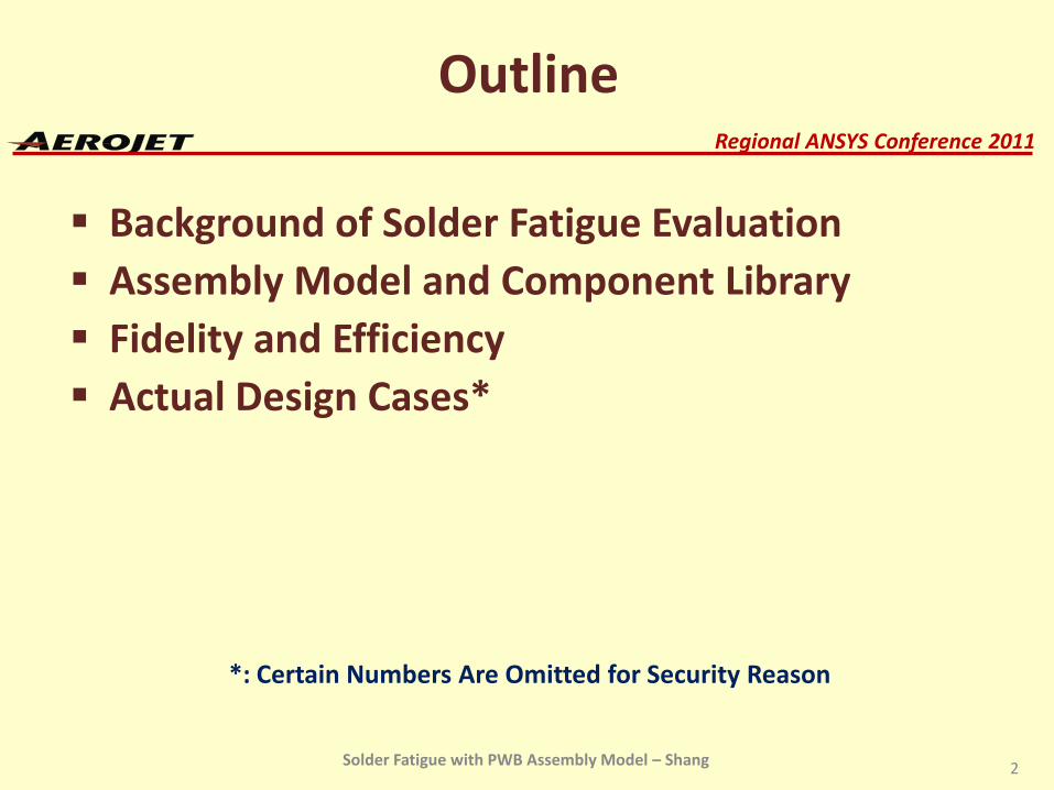
Outline
Background of Solder Fatigue Evaluation Assembly Model and Component Library Fidelity and Efficiency Actual Design Cases*
*: Certain Numbers Are Omitted for Security Reason
2Solder Fatigue with PWB Assembly Model – Shang

Regional ANSYS Conference 2011
Some PWB May Contain Hundreds of Electronic Components, and Thousands of Solder Joints Solder Fatigue in Dynamic Environments Has
Been a Major Failure Mode Fatigue Evaluation Is Based on Solder Stress in Dynamic Environment Solder Material’s Fatigue Strength (S-N Curve)
The Challenge Is to Determine Solder Stress –Reliably, and For Thousands of Them!
Background of Solder Fatigue Evaluation
3Solder Fatigue with PWB Assembly Model – Shang
Regional ANSYS Conference 2011
Assembly Model and Component Library
It Is Well Understood that An Assembly Model Has the Following Advantages Captures Component Interaction
Captures System Load Path
And Thus Provides Fidelity Prediction on Solder Joint Response
But An Assembly Model Would Be Very Costly Can the Problems Be Solved?
4Solder Fatigue with PWB Assembly Model – Shang
Regional ANSYS Conference 2011
Assembly Model and Component Library (Cont’d)
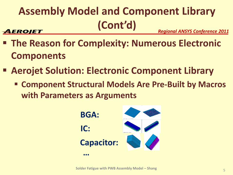
The Reason for Complexity: Numerous Electronic Components
Aerojet Solution: Electronic Component Library Component Structural Models Are Pre-Built by Macros
with Parameters as Arguments
5
BGA:
IC:
Capacitor:…
Solder Fatigue with PWB Assembly Model – Shang
Regional ANSYS Conference 2011
Assembly Model and Component Library (Cont’d)
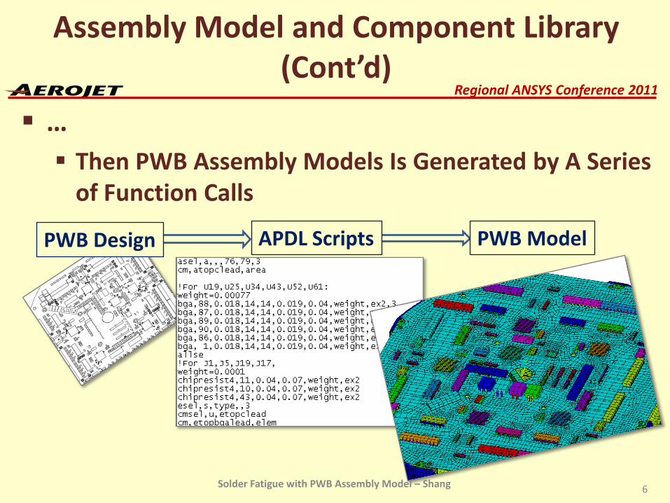
… Then PWB Assembly Models Is Generated by A Series
of Function Calls
6
PWB Design APDL Scripts PWB Model
Solder Fatigue with PWB Assembly Model – Shang
Regional ANSYS Conference 2011
Fidelity and Efficiency
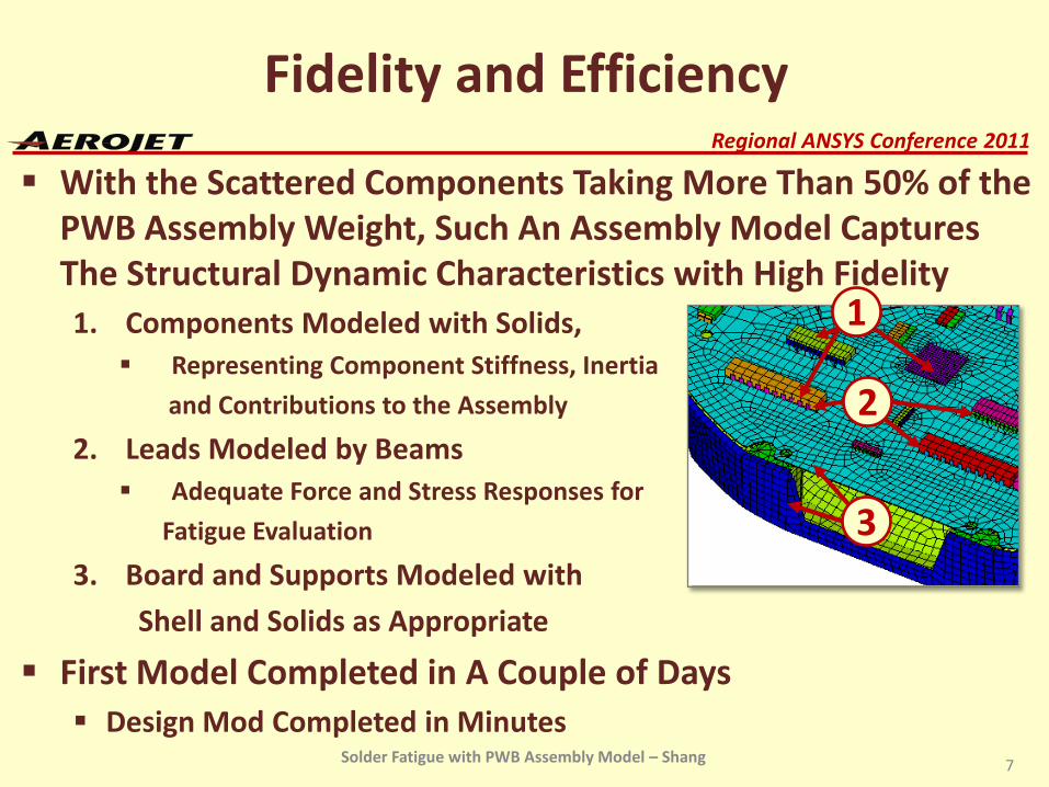
With the Scattered Components Taking More Than 50% of the PWB Assembly Weight, Such An Assembly Model Captures The Structural Dynamic Characteristics with High Fidelity1. Components Modeled with Solids, Representing Component Stiffness, Inertia
and Contributions to the Assembly
2. Leads Modeled by Beams Adequate Force and Stress Responses for
Fatigue Evaluation
3. Board and Supports Modeled with
Shell and Solids as Appropriate
First Model Completed in A Couple of Days Design Mod Completed in Minutes
7
1
2
3
Solder Fatigue with PWB Assembly Model – Shang
Regional ANSYS Conference 2011
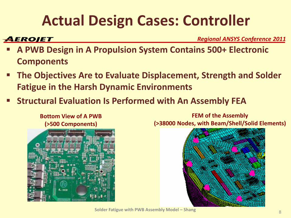
Actual Design Cases: Controller
A PWB Design in A Propulsion System Contains 500+ Electronic Components
The Objectives Are to Evaluate Displacement, Strength and Solder Fatigue in the Harsh Dynamic Environments
Structural Evaluation Is Performed with An Assembly FEA
8
Bottom View of A PWB (>500 Components)
FEM of the Assembly(>38000 Nodes, with Beam/Shell/Solid Elements)
Solder Fatigue with PWB Assembly Model – Shang
Regional ANSYS Conference 2011
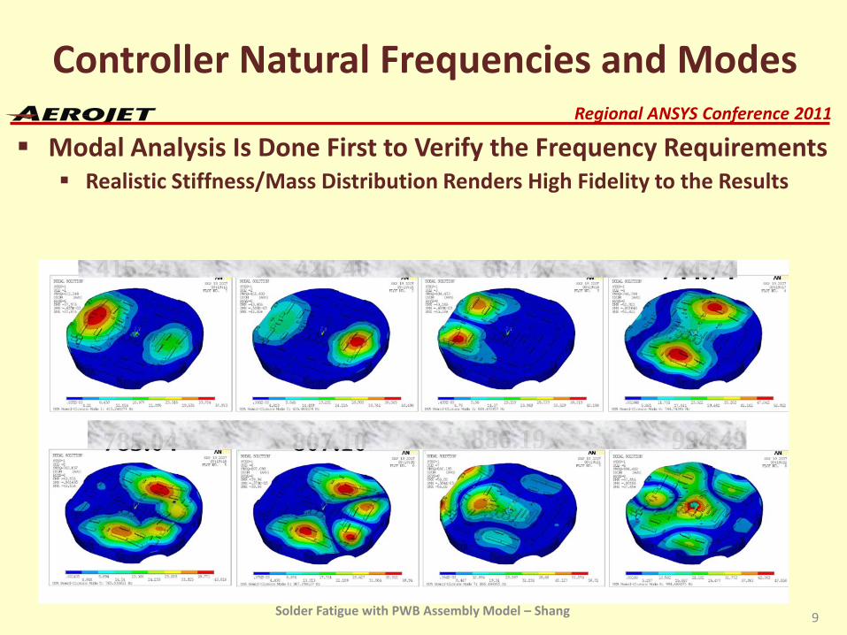
Controller Natural Frequencies and Modes
Modal Analysis Is Done First to Verify the Frequency Requirements Realistic Stiffness/Mass Distribution Renders High Fidelity to the Results
9
415.24 426.40 604.47 744.74
785.04 807.10 886.19 994.49
Solder Fatigue with PWB Assembly Model – Shang
Regional ANSYS Conference 2011
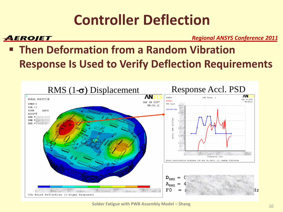
Then Deformation from a Random Vibration Response Is Used to Verify Deflection Requirements
10
Controller Deflection
RMS (1-σ) Displacement Response Accl. PSD
DRMS = 0.000786 inARMS = 4889 in/s2
F0 = sqrt(A/D)/(2*π) = 397 Hz
Solder Fatigue with PWB Assembly Model – Shang
Regional ANSYS Conference 2011
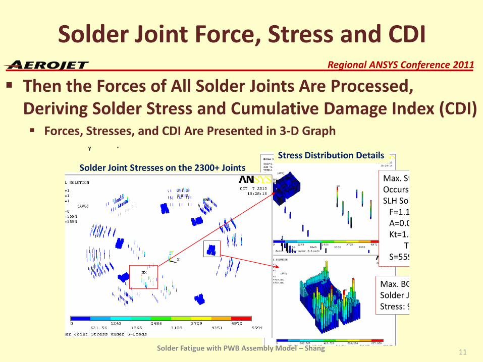
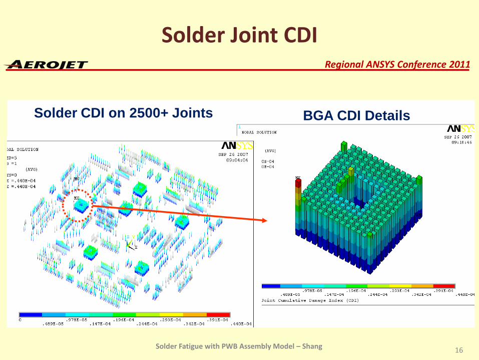
Solder Joint Force, Stress and CDI
Then the Forces of All Solder Joints Are Processed, Deriving Solder Stress and Cumulative Damage Index (CDI) Forces, Stresses, and CDI Are Presented in 3-D Graph
11
y /
Solder Joint Stresses on the 2300+ JointsMax. St Occurs SLH Sol
F=1.1 A=0.0Kt=1.2
ThS=559
Max. BG Solder Jo Stress: 9
Stress Distribution Details
Solder Fatigue with PWB Assembly Model – Shang
Regional ANSYS Conference 2011
Conclusions
PWB Assembly Analysis Provides High Fidelity Structural Dynamic Responses Component Library Makes Assembly Analysis
Efficient Solder Joint Results Presented in 3-D Graph Are
Very Informative
Much Yet to Be Done to Improve, and Correlate with Tests
12Solder Fatigue with PWB Assembly Model – Shang
Regional ANSYS Conference 2011
Additional Info
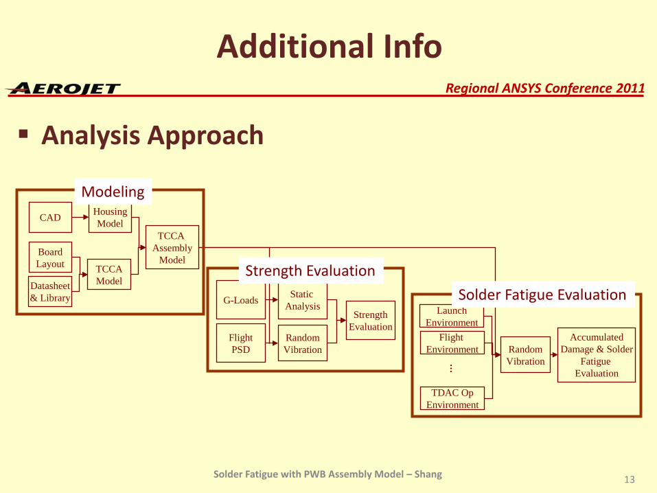
Analysis Approach
CAD HousingModel
BoardLayout
Datasheet& Library
TCCAModel
TCCA Assembly
Model
G-Loads Static Analysis
FlightPSD
RandomVibration
StrengthEvaluation
LaunchEnvironment
Flight Environment
TDAC OpEnvironment
…
RandomVibration
AccumulatedDamage & Solder
Fatigue Evaluation
Modeling
Strength Evaluation
Solder Fatigue Evaluation
13Solder Fatigue with PWB Assembly Model – Shang
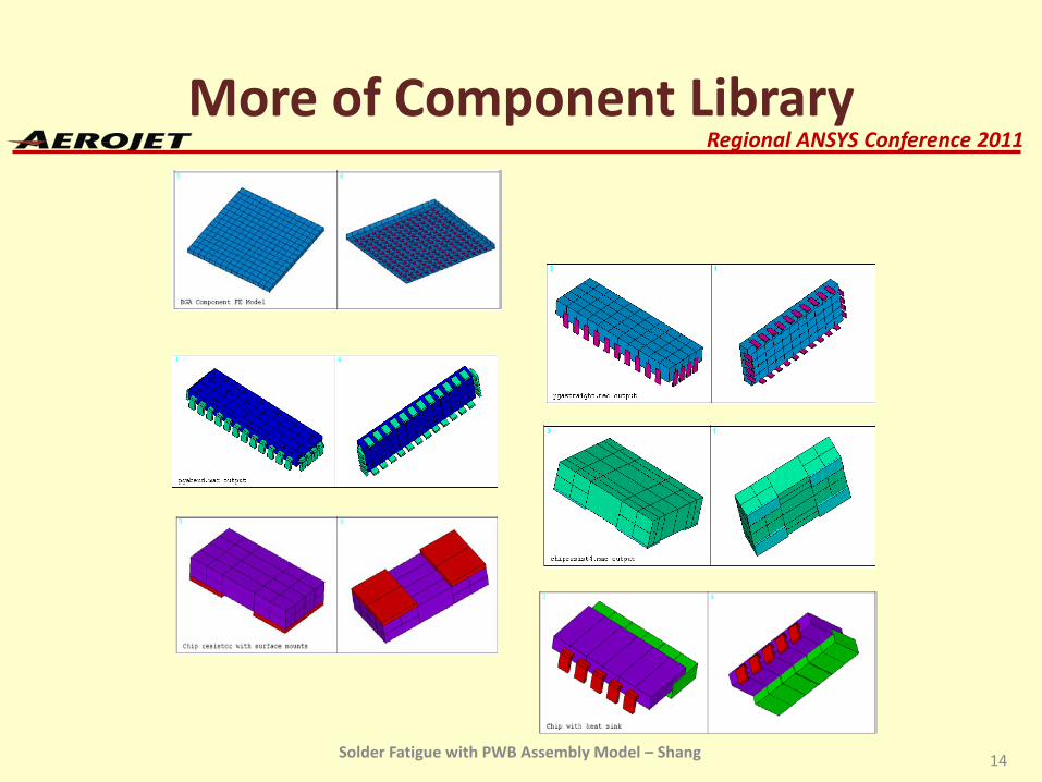
Regional ANSYS Conference 2011More of Component Library
14Solder Fatigue with PWB Assembly Model – Shang
Regional ANSYS Conference 2011
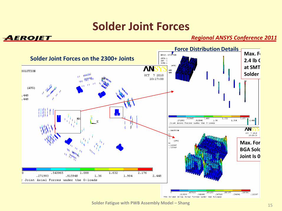
Solder Joint Forces
Solder Joint Forces on the 2300+ Joints
Force Distribution DetailsMax. Fo 2.4 lb O at SMT Solder
Max. For BGA Sold Joint Is 0
15Solder Fatigue with PWB Assembly Model – Shang
Regional ANSYS Conference 2011
Solder Joint CDI
Solder CDI on 2500+ Joints BGA CDI Details
16Solder Fatigue with PWB Assembly Model – Shang
Regional ANSYS Conference 2011
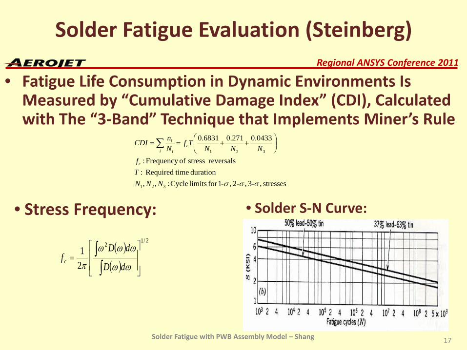
Solder Fatigue Evaluation (Steinberg)
• Fatigue Life Consumption in Dynamic Environments Is Measured by “Cumulative Damage Index” (CDI), Calculated with The “3-Band” Technique that Implements Miner’s Rule
stresses ,3 ,2 ,1for limits Cycle :,,duration timeRequired :
reversals stress ofFrequency :
0433.0271.06831.0
321
321
σσσ ---NNNTf
NNNTf
NnCDI
c
ci i
i
++==∑
( )( )
2/12
21
=
∫∫
ωω
ωωω
π dD
dDfc
• Stress Frequency: • Solder S-N Curve:
17Solder Fatigue with PWB Assembly Model – Shang