
Solco Technical Final
28
Transcript of Solco Technical Final

7/29/2019 Solco Technical Final
http://slidepdf.com/reader/full/solco-technical-final 1/28

7/29/2019 Solco Technical Final
http://slidepdf.com/reader/full/solco-technical-final 2/28
!")!&%
&34=2?4/0A,=;?-74=30/A4>349>301<,80A:<6:1>30%"";<:50.>A34.34=.:149,9.0/-C>30 9>0774209>90<2C?<:;0
;<:2<,880
)0,<02<,>01?7>:,77>3:=0A3:3,@0.:9><4-?>0/A4>3>304<A:<649;<0;,<492A<4>492,9/<0@40A492>34=;?-74.,>4:9?<>30<8:<0
A0A:?7/7460>:0B;<0==:?<>3,96=>:>30B0.?>[email protected]:<:8;0>4>4@090==,9/99:@,>4:91:<>304<2?4/,9.0,9/
=?;;:<>
'&"$% <#,9:=:<:C,99,64=%!&==#<:1&30:.3,<4=&=:?>=:=,9/+,.3,<4,=6:?=6:=&!'!($%&*
"$&%>01,9:$?224909>4,9/%,7@,>:<0,=>,7/:#2<4209>:
#$"&%&$!"&&%>01,9:$?224909>4%,7@,>:<0,=>,7/:#2<4209>:#<:50.>::</49,>:<,<4:=,9:74=
#,9:=:<:C,99,64=%!/,<!,@,<<:$4@0<:&&30:.3,<4=&=:?>=:=&'
#! """ "
#!#
!"
#$"'$,9/&"$%!&
$#%!#4B07;7?=$&( !#$"'&"!%'#$(%"! %>,@<:?7,&:?<9,64
)&&%'##"$&I
!"&
&30=:70<0=;:9=4-474>C1:<>30.:9>09>:1>34=;?-74.,>4:9740=A4>3 >30,?>3:<=>/:0=9:>90.0==,<47C<0170.>>30:;494:9:1
>30?<:;0,9 :88?94>40= &30?<:;0,9:884==4:94=9:><0=;:9=4-701:<,9C?=0>3,>8,C -08,/0:1>30491:<8,>4:9.:9>,490/>30<049

7/29/2019 Solco Technical Final
http://slidepdf.com/reader/full/solco-technical-final 3/28
1. Introduction - The SOLCO Project . . . . . 3
2. Layout of Solar Cooling Installations . . . 6
3. Solar Heating and Cooling:
Basic Principles . . . . . . . . . . . . . . . . . . . 12
4. Solar Cooling Installations -
Case Studies . . . . . . . . . . . . . . . . . . . . . 14
5. Barriers and Recommendations . . . . . . 19
6. Economic & Financial Considerations . . 21
7. Conclusions . . . . . . . . . . . . . . . . . . . . . . 24
Contents
SOLAR COOLING: Overview and Recommendations

7/29/2019 Solco Technical Final
http://slidepdf.com/reader/full/solco-technical-final 4/28
2
SOLAR COOLING: Overview and Recommendations

7/29/2019 Solco Technical Final
http://slidepdf.com/reader/full/solco-technical-final 5/28
3
SOLAR COOLING: Overview and Recommendations
Cooling from renewable energies, particularly
solar cooling (SC) technologies, represents a key
issue within the European Union energy policy.
The higher temperatures experienced in SouthernEurope widely attributed to climate change conti-
nue to increase the summer energy demand for
air-conditioning. Employing the power of the sun
(figure 1.1) can substantially reduce electricity
peaks during the summer months and at the same
time reduce CO2
emissions.
Solar heating, a widely accepted concept for hot
water production enjoys a high level of market
penetration and is widely accepted by the general
public. SC, however, although a mature technolo-
gy, has rather low levels of market penetration and
public acceptance. This is due to a number of non-
technological barriers such as its relatively higher
initial investment costs compared to traditional air
conditioning installations.
SOLCO’s global aim is the removal of the non-
technological barriers in an effort to improve the
penetration and acceptance of SC technologies
and chilling systems.
In order to meet this objective the project endea-
voured to achieve the following:
• the identification of the non-technological bar-
riers that hinder the implementation and use of
solar technologies and chilling systems
• the training of the market actors and potential
users and
• the raising of awareness regarding these tech-
nologies and a large and targeted campaign of
dissemination of information and results.
The long term objective of the project is to encou-rage and facilitate the implementation of SC tech-
nologies and to support their use in Southern Euro-
pean insular territories and areas, particularly those
associated with high levels of solar radiation.
The dissemination of data and information, as well
as the advice given during professional targetedtraining sessions and courses are expected to fur-
ther support the wider and faster diffusion of this
renewable energy source (solar energy).
Project results
The results of the project are:
• Increased awareness of the benefits and oppor-
tunities offered by the wider penetration and uti-
lisation of SC technologies
• Evaluation of solar technologies (including chil-
lers)
• Market characteristics in each participating island
• A detailed analysis of the non-technical market
barriers of both heating and cooling technolo-
gies and recommendations to overcome them
• Training of key market actors in insular areas
and the development of a methodology and
multilingual training material to train various
categories of professionals involved in SC and
chilling systems.
A database of solar collectors and chillers com-mercially available in the four islands participating
in the project has been developed and is available
online on the project web site.
Local Action Committees
The development of SOLCO is based on effective
and permanent communication between partners
and all various categories of market actors and sta-
keholders. These key players were represented
within four Local Action Committees (LAC) created
at the beginning of the project in each insular part-
ner area.
Introduction
The SOLCO Project1

7/29/2019 Solco Technical Final
http://slidepdf.com/reader/full/solco-technical-final 6/28
4
SOLAR COOLING: Overview and Recommendations
The members of the LAC are typically local desi-
gners, installers and equipment suppliers if they
are locally present, SMEs, public bodies, such as
the local government, the regional government,the chamber of commerce, and potential users,
particularly hotels, resorts, hospitals and universi-
ties. Each key actor has provided useful contribu-
tions and input that have been critical for the suc-
cess of the project.
There have been several meetings in the four
islands participating in the project: Sicily, Crete,
Canary Islands and Cyprus.
The main findings derived from the LAC meetings
are:
• The subject matter is quite innovative and peo-
ple feel that they need both technical and finan-
cial guidance to approach it and adopt it
• Financial aid is one of the main preoccupations
of potential users
• SC technologies should be included in financial
incentive schemes (national and European)
• One important barrier with respect to the suc-
cess of financial schemes is the bureaucratic
approval procedure
• Demonstration of the technology plays a crucialrole, even if it is just in one building of the com-
munity
• Successful introduction of solar technologies
should have strong links with the government’s
overall climate change policies and environ-
mental priorities
• It is necessary to further develop solar techno-
logy design tools (advanced modelling and
simulation tools) in order to improve the systems
used and reduce costs of implementation
• Alternatives to the cooling tower should be
developed in order to avoid the risk of legion-
naires’ disease and the related treatment which
is quite costly
• There is a significant number of prime candida-
tes for the implementation of SC technologies,
such as hotels, resorts and hospitals in the
Mediterranean area
Figure 1.1: Solar Insolation in Europe. Source: GRID - Arendal
Solar insolation, annual
average (kWh/m2/day

7/29/2019 Solco Technical Final
http://slidepdf.com/reader/full/solco-technical-final 7/28
5
SOLAR COOLING: Overview and Recommendations
Training Activities
Another important task of the SOLCO project was
the development of training material and the orga-
nisation of training courses in each of the four part-ner areas. Each course has a maximum duration
of 5 days and has been designed according to the
needs and characteristics of the local actors it
addresses:
•Designers
•Installers / Producers
•Private Potential users
•Public Potential Users
The general content of the training courses is as
follows:
Outline of Designers & TechnicalExpertsTraining
• Climatology (Solar Radiation, Air temperature) -
Solar Collectors (Typologies, characteristics)
• Chiller Systems
• The Building - Normative Matters - Plant Design
• Financial Matters (cost evaluation, access to
financing, supply contracts) – Case Studies
• Workshop - Final Test of Knowledge
Outline of Potential Users Training
• The Building - Chiller Systems
• Climatology - Solar Collectors (Typologies,
Characteristics)
• Normative Matters - Financial Matters
• Choice of Plant Layout - Case Studies
• Workshop
Information dissemination
The dissemination effort has as its main objective
to reach as many key stakeholders as possible
and to inform the general public on the advanta-ges of SC technologies. The main dissemination
tools used were:
• A fully dynamic website that contains all relevant
project information as well as extensive infor-
mation on SC technologies and equipment
available in the four island-partners. The websi-
te has registered more than 100.000 hits during
2008
• Seven electronic newsletters
• A promotional leaflet in four languages (English,Greek, Italian and Spanish) and
• This technical brochure
In addition to the above tools the partners were
involved in the following activities:
• participation in technical conferences and pre-
sentation of the SOLCO activities
• several visits to local SC plants, such as in
Palermo, Italy and the SC installation of the ITC
- Canary Islands Institute of Technology
• meetings with partners of similar projects, suchas SOLAIR and SOLARCOMBI+, in order to
exchange information and share know-how, and
• publication of articles in local newspapers and
technical journals for the dissemination of the
SOLCO work and the SC technology
More details on the SOLCO project and its delive-
rables can be found at: www.solcoproject.net
7/29/2019 Solco Technical Final
http://slidepdf.com/reader/full/solco-technical-final 8/28
6
SOLAR COOLING: Overview and Recommendations
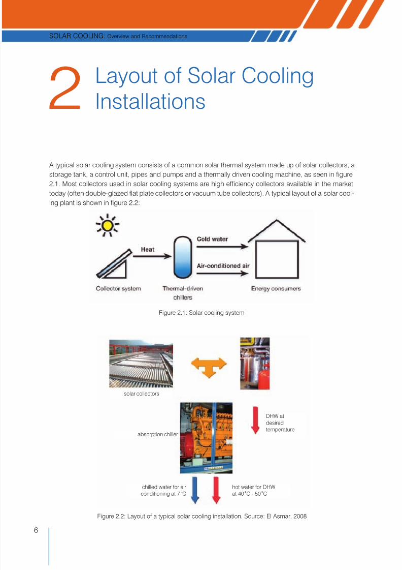
A typical solar cooling system consists of a common solar thermal system made up of solar collectors, a
storage tank, a control unit, pipes and pumps and a thermally driven cooling machine, as seen in figure
2.1. Most collectors used in solar cooling systems are high efficiency collectors available in the market
today (often double-glazed flat plate collectors or vacuum tube collectors). A typical layout of a solar cool-
ing plant is shown in figure 2.2:
Figure 2.1: Solar cooling system
solar collectors
absorption chiller
DHW atdesiredtemperature
chilled water for airconditioning at 7 oC
hot water for DHWat 40 oC - 50 oC
Figure 2.2: Layout of a typical solar cooling installation. Source: El Asmar, 2008
Layout of Solar Cooling
Installations2

7/29/2019 Solco Technical Final
http://slidepdf.com/reader/full/solco-technical-final 9/28
7
SOLAR COOLING: Overview and Recommendations
The available solar energy, in the form of solar radiation flux, is utilised by a solar panel, in order to pro-
duce a high temperature fluid (generally water) that is accumulated in a storage tank.
The chiller, the real heart of the process, uses the hot fluid of the storage tank to produce a cold fluid; the
cold fluid can then be used in a normal cooling plant similar to an electric refrigerator.
On a typical day, the thermal storage tank acts as a buffer and enables the optimisation of the asynchro-
nous heat absorption during the hours of solar radiation and the cooling that may be needed during a dif-
ferent time period making this component indispensable.
Another commonly used layout, that is very common for installations on which the plant has to be utilised
during both winter (for heating) and summer (for cooling), is the one shown in figure 2.3. In this layout two
tanks are necessary: one for the storage of hot water produced by the solar thermal panels and a second
for the storage of cold liquid produced by the absorption machine (chiller). One conventional backup heat
source (e.g. a natural gas boiler) is also present. The backup heat source makes the operating hours of
the solar cooling plant independent from the availability of solar radiation.
Figure 2.3: Basic layout of a solar cooling plant utilised during summer and winter
heat distributionsystem
backupheat source
absorption chiller
cooling tower
solar collectors
summer
winter
hot water storage tank
cold water storage tank
Solar assisted air conditioning systems may be classified into closed or open systems:
1. Closed systems: these are thermally driven chillers, which provide chilled water; that is either used in
air handling units to supply conditioned air or that is distributed via a chilled water network to the des-
ignated rooms to operate decentralised room installations. Equipment available in the market for this
purpose is of two types: absorption chillers and adsorption chillers (figure 2.4).
Figure 2.4: Closed systems

7/29/2019 Solco Technical Final
http://slidepdf.com/reader/full/solco-technical-final 10/28
8
SOLAR COOLING: Overview and Recommendations
2. Open systems: Desiccant cooling systems are basically open cycle systems, using water as a refrig-
erant in direct contact with air. The thermally driven cooling cycle is a combination of evaporative cool-
ing with air dehumidification by a desiccant. For this purpose, liquid or solid materials can be employed.
The term ”open” is used to indicate that the refrigerant is discarded from the system after providing the
cooling effect, and new refrigerant is supplied in its place in an open-ended loop. The common tech-
nology applied today uses rotating desiccant wheels, equipped either with silica gel or lithium-chloride
as sorption material.
For the choice of the type of chillers, the following parameters have to be evaluated in advance:
• The operating temperatures of the absorption machine, as they affect the choice of solar collectors.
• The values of the coefficient of performance (COP) of the chiller, as they change according to the above
mentioned temperatures and also according to the heat distribution system installed (e.g. fan-coils or
radiant floor).
The choice of the type of solar collectors is not a difficult task. The functioning temperature of the ab-
sorption chiller determines the most suitable typology of collectors for different layouts. Dimensioning of
the panels surface follows the same rules of domestic solar plants for hot water production, even though
the fact that a solar cooling plant operates at higher temperatures has to be taken into account.
2.1 Solar collectors for solar cooling systemsSolar collectors transform solar radiation into heat and transfer that heat to a medium (water, solar fluid,
or air). The solar heat can then be used for hot water, heating or cooling systems, or for heating swim-
ming pools. Solar cooling technologies demand high temperatures (90-150oC); collectors that can
achieve such temperatures are evacuated tube and selective coated flat-plate solar collectors. A solar
collector array supplies hot water as a source of energy to the absorption chiller through a hot water stor-
age tank.
Flat-plate solar collectors
Flat-plate collectors are the most widely used kind of collectors for domestic water-heating systems and
solar space heating/cooling. A typical flat plate collector consists of an absorber, transparent cover
sheets, and an insulated box. The absorber is usually a sheet of high thermal conductivity metal such as
Figure 2.5: Οpen systems

7/29/2019 Solco Technical Final
http://slidepdf.com/reader/full/solco-technical-final 11/28
9
SOLAR COOLING: Overview and Recommendations
copper or aluminium, with tubes either integral or attached. Its surface is coated to maximise radiant ener-
gy absorption and to minimise radiant emission. The insulated box reduces heat loss from the back or
the sides of the collector. The cover sheets, called glazing, allow sunlight to pass through the absorber
but also insulate the space above the absorber to prevent cool air to flow into this space.
Evacuated (or Vacuum) Tubes
Glass evacuated tubes are the key component of the Evacuated Tube Heat Pipe solar collectors. Each
evacuated tube consists of two glass tubes. The outer tube is made of extremely strong transparent
borosilicate glass (i.e. Pyrex) that is able to resist impact from hail up to 25mm in diameter. The inner tube
is also made of borosilicate glass, but coated with a special selective coating, which possesses excel-
lent solar heat absorption and minimal heat reflection properties. The air is evacuated from the space
between the two glass tubes to form a vacuum, which eliminates conductive and convective heat loss.
The vacuum tube solar panel has been around for several years and has proved to be both reliable and
dependable. The double wall glass Pyrex tubes have a space in the centre which contains the heat pipe.
The solar radiation is absorbed
by the selective coating on the
inner glass surface, but is pre-
vented from re-radiating out by
the silver coated innermost lining
which has been optimised for
infrared radiation. This acts simi-
larly as an one-way mirror.
This is very efficient: 93% of the
sun light's energy hitting the
tube's surface, is absorbed,whereas only 7% is lost through
reflection and re-emission. The presence of the vacuum wall prevents any losses by conduction or con-
vection - just like a thermos flask. Because of this, the system will work even in very low temperatures,
unlike traditional flat plate collectors.
The heat transferred to the tip of the heat pipe is in turn transferred to a copper manifold in which water
circulates to heat the domestic hot water tank. If a tube is placed in direct sunlight on a summer day, the
tip temperature can reach 250°C, so the system easily heats domestic hot water cylinders to 60°C even
in cooler weather.
The manifold is heavily insulated with a 2" thickness of pre-formed rock wool. Unlike flat plates, these
headers are so well insulated that they should not require antifreeze in normal operation - the tempera-
ture of the header is unlikely to fall below 10°C even in very cold weather.
Figure 2.6: A flat plate collector
Outer glass tube Absorbing coatingInner glass tubeFluid tubesCopper sheetEvacuated space
Evacuated tube
Crosssection
Inflow
Outflow
Reflector
Glazing
GlazingGlazing frame
EnclosureFlow tubes
Absorber plate
Insulation
Outletconnection
Inletconnection
Figure 2.7: A vacuum tube collector

7/29/2019 Solco Technical Final
http://slidepdf.com/reader/full/solco-technical-final 12/28
10
SOLAR COOLING: Overview and Recommendations
2.2 ChillersChillers are the core of solar cooling plants. If solar panels provide the necessary energy input to the
plant, chillers are those machines that are able to produce cooling by utilising the hot water coming from
the solar panels. More precisely, a chiller is a machine that removes heat from a liquid via a vapour com-
pression or absorption refrigeration cycle. Most often water is chilled, but this water may also contain
20% glycol and corrosion inhibitors; other fluids such as thin oils can be chilled as well.
There are different types of chillers: absorption or adsorption chillers have been used for decades but
have been powered mainly by electric motors, steam, or gas turbines. They produce their cooling effect
via the "reverse-Rankine" cycle, also known as "vapour compression".
Absorption chillers’ thermodynamic cycle is driven by a heat source. This heat is usually delivered to the
chiller via steam, hot water, or combustion but, in the sunny climates of South Europe, solar energy canbe used to operate absorption chillers.
Compared to electrically powered chillers, they have very low electrical power requirements, very rarely
above 15kW combined consumption for both the solution pump and the refrigerant. However, their heat
input requirements are large, and their coefficients of performance (COP) are often 0.5 (single effect) to
1.0 (double effect). For the same tonnage capacity they require larger cooling towers than vapour com-
pression chillers.
However, absorption chillers, from an energy efficiency point of view, excel where cheap heat is readily
available such as heat provided by solar thermal panels in sunny regions.
Absorption chillers are the most widely used chillers throughout the world. A thermal compression of the
refrigerant is achieved by using a liquid refrigerant/absorbent solution and a heat source, thereby replac-ing the electric power consumption of a mechanical compressor. For chilled water above 0°C, as is used
in air conditioning, a liquid H2O/LiBr solution is typically applied with water as a refrigerant.
The main components of an absorption chiller are shown in the figure 2.8. The cooling effect is based on
the evaporation of the refrigerant (water) in the evaporator at very low pressure. The vaporised refrigerant
is absorbed in the absorber, thereby diluting the H2O/LiBr solution.
A few absorption chillers with capacities below 50kW are available. Typical chilling capacities of absorp-
tion chillers are several hundred kW.
Adsorption chillers apply solid sorption materials instead of a liquid solution. Systems available in the
market today use water as a refrigerant and silica gel as a sorption material. The machines consist of twosorption compartments (denoted as 1 and 2 in figure 2.9), one evaporator and one condenser. Under
typical operating conditions, at about 80°C, the systems achieve a COP of about 0,6, but operation is
Figure 2.8 Principle of an absorption chiller. Source: ESTIF

7/29/2019 Solco Technical Final
http://slidepdf.com/reader/full/solco-technical-final 13/28
11
SOLAR COOLING: Overview and Recommendations
possible even at heat source temperatures of approx. 60°C. The capacity of the chillers ranges from 50
to 500kW chilling power.
Figure 2.9: Principle of an adsorption chiller. Source: ESTIF
Table 2.1. Comparison of the main sorption and desiccant technologies
Systems Advantages Disadvantages
Absorption
• Only one moving part (pump) with possibly
no moving part for a small system
• Low-temperature heat supply is possible
• Low COP
• It cannot achieve a very low evaporating
temperature
• The system is quite complicated
Adsorption
• No moving parts (except valve)
• Low operating temperature can be achieved
• Thermal Coefficient of Performance (COP) is
quite high compared to other heat operating
systems
• High weight and poor thermal conductivity
of the absorbent
• Low operating pressure requirement makes
it difficult to achieve air-tightness
• Very sensitive to low temperatures especially
the decreasing temperature during night-time
• It is an intermittent system
Desiccant
• Environmentally friendly, water is used as theworking fluid
• Can be integrated with a ventilation and
heating system
• It cannot function properly in a humid area
• It is not appropriate for an area where water
is scarcity
• Requires maintenance due to moving part
in a rotor wheel
Table 2.1 compares the main sorption and desiccant technologies and summarises their advantages and
disadvantages.
The very scarce number of producers of solar assisted chillers within the global market is one of the rea-
sons why solar cooling plants are still too few in spite of their environmental advantages in terms of low
electricity consumption.
A survey of chiller machines available in Southern European islands participating in the SOLCO project is available on www.solcoproject.net , in the section dedicated to project deliverables. Data sheets can be
downloaded in order to get all the necessary technical information required for a SC plant dimensioning.
Source: CLIMASOL project

7/29/2019 Solco Technical Final
http://slidepdf.com/reader/full/solco-technical-final 14/28
12
SOLAR COOLING: Overview and Recommendations
This chapter briefly defines certain basic terms used in the design of solar cooling installations and
describes the basic principles of the heat balance calculations that are necessary in order to ensure that
the cooling capacity of the equipment is adequate.
Solar HeatingThe calculation of summer thermal gains in solar installations needs to consider the time variability of heat
gains, due to quick variations of solar radiation across the whole day. Instantaneous thermal flux (defined
as the heat that penetrates into a structure at any given point in time) entering a building does not turn
itself immediately into a heating gain because of the thermal inertia of structures. It is therefore important
to take notice of that in order to avoid errors when estimating cooling plant capacity.
The proper way to proceed in designing solar cooling installations is to calculate the cooling load as well
as the exact heat extraction rate.
Figure 3.1: Solar Cooling installation
Solar Heating and Cooling:
Basic Principles3

7/29/2019 Solco Technical Final
http://slidepdf.com/reader/full/solco-technical-final 15/28
13
SOLAR COOLING: Overview and Recommendations
Space heating gains
The thermal flux entering a space can be distinguished in two types:
(i) Flux of direct heat
• Solar radiation through window frames (heat transmission by radiation)
• Transmission through window frames (heat transmission by conduction - heat transmission by con-
vection)
• Transmission through the outside walls and roof (heat transmission by conduction or by convection)
• Transmission through the inside walls, ceilings and floors (heat transmission by conduction or by con-
vection)
• Indoor heat generation (due to people, lights, electric instruments)
• External air infiltration
• Possible other contingent causes
(ii) Flux of latent heat
• External air infiltration (with more specific humidity than indoor air)
• Steam due to indoor people
• Transmission through external walls and covering
• Steam due to particular processes or instruments located into the ambient
Space cooling load
Space cooling load is the heat that has to be removed (or extracted) from a space in order to keep the
desired temperature constant. As a matter of fact, heat transmission by radiation is not directly convert-
ed into space cooling load: radiant energy is first absorbed by all surfaces that delimit the space (walls,
ceilings and floors) and then transferred to the air. Thus there is a lag between the thermal capacity of all
surfaces fixes the rate of temperature increase, defining amplitude and delay time of each heat flux trans-ferred to the space as opposed to the heat of instantaneous radiation.
Space heat extraction rate As the ambient temperature does not remain constant and stable across the day, the amount of heat to
be removed will be different from the cooling load. These proportions change in relation to internal and
external condition changes (fig. 3.2). The space heat extraction rate is equal to the space cooling load
only in the case when the room temperature is kept constant. This, however doesn’t happen frequently.
Instantaneous
heat gain
Furnishings,
structure
variable heat
storage
Convection
(with time delay)
Radiative
component
Convective component Instantaneous
cooling load
Heat extraction
by equipment
Figure 3.2: Schematic representation of the relation among thermal flux, cooling load and heat extraction rate

7/29/2019 Solco Technical Final
http://slidepdf.com/reader/full/solco-technical-final 16/28
14
SOLAR COOLING: Overview and Recommendations
This chapter presents a number of successful solar cooling installations that have been designed in three
Mediterranean islands participating in the project and in Bolzano, Italy.
4.1 Solar Cooling at the Technological Instituteof Canary IslandsSince 2006, this installation is used to produce chilled water which acts as a refrigerant for the air condi-
tioning units used to chill an office building of 400m2
The solar collector field consist of nine flat plate collectors model Wagner LB 7,6. These solar collectors
have a selective surface. As they are of high performance, they can reach 80 oC. The collector surface is
68,4m2. The installation has two tanks, a 3.000l hot water storage tank and a 1.000l chilled water storage
tank. The absorption process takes place in the Yazaki absorption chiller (model WFC-SC10), whose no-
minal power is 35,2 kW. In the following photographs (figure 4.2 - 4.3) the absorption chiller and the coo-
ling tower are presented.
Figure 4.1: Solar collector field
Figure 4.2: Absorption Chiller Figure 4.3: Cooling Tower
Solar Cooling Installations -
Case Studies4
7/29/2019 Solco Technical Final
http://slidepdf.com/reader/full/solco-technical-final 17/28
15
SOLAR COOLING: Overview and Recommendations
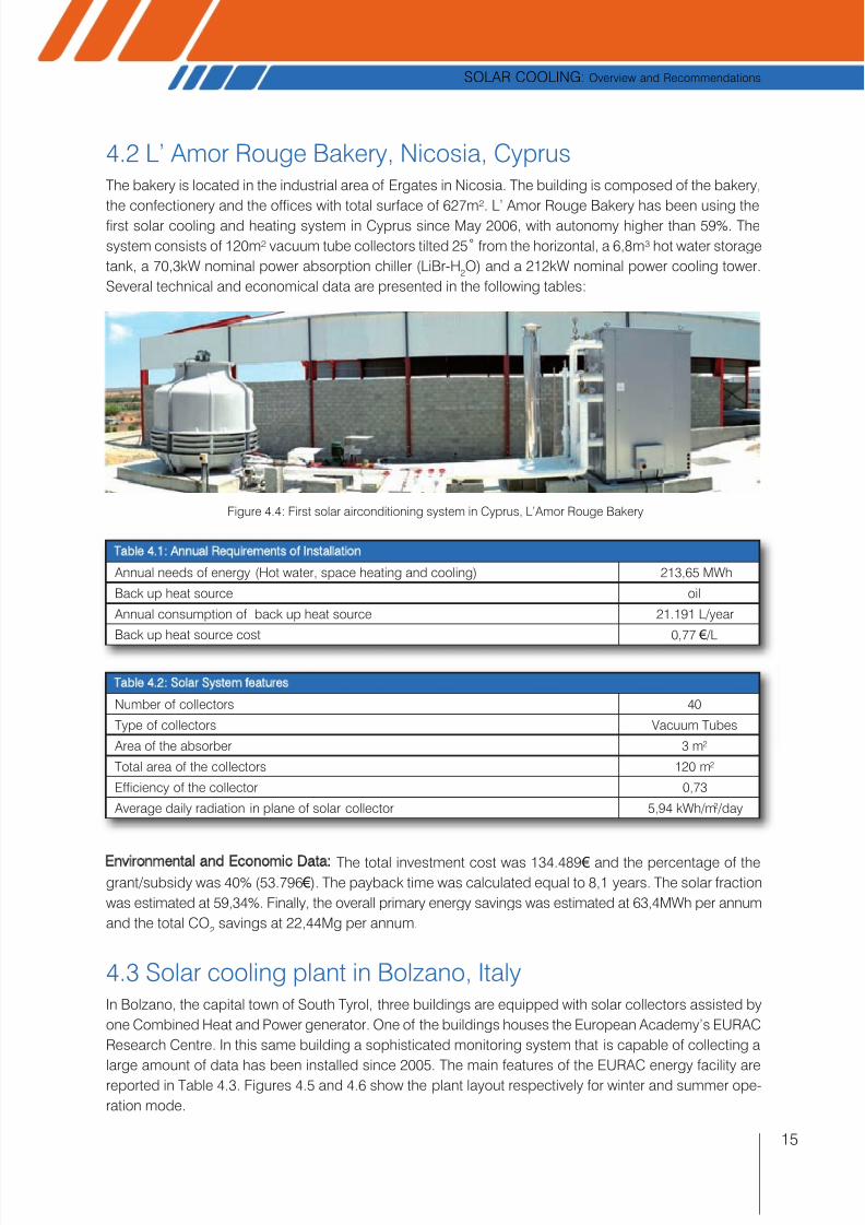
Figure 4.4: First solar airconditioning system in Cyprus, L’Amor Rouge Bakery
4.2 L’ Amor Rouge Bakery, Nicosia, CyprusThe bakery is located in the industrial area of Ergates in Nicosia. The building is composed of the bakery,
the confectionery and the offices with total surface of 627m². L’ Amor Rouge Bakery has been using the
first solar cooling and heating system in Cyprus since May 2006, with autonomy higher than 59%. The
system consists of 120m² vacuum tube collectors tilted 25° from the horizontal, a 6,8m³ hot water storage
tank, a 70,3kW nominal power absorption chiller (LiBr-H2O) and a 212kW nominal power cooling tower.
Several technical and economical data are presented in the following tables:
Table 4.1: Annual Requirements of Installation
Annual needs of energy (Hot water, space heating and cooling) 213,65 MWh
Back up heat source oil
Annual consumption of back up heat source 21.191 L/year
Back up heat source cost 0,77 € /L
Table 4.2: Solar System features
Number of collectors 40
Type of collectors Vacuum Tubes
Area of the absorber 3 m2
Total area of the collectors 120 m2
Efficiency of the collector 0,73
Average daily radiation in plane of solar collector 5,94 kWh/m2 /day
Environmental and Economic Data: The total investment cost was 134.489 € and the percentage of thegrant/subsidy was 40% (53.796 €). The payback time was calculated equal to 8,1 years. The solar fraction
was estimated at 59,34%. Finally, the overall primary energy savings was estimated at 63,4MWh per annum
and the total CO2
savings at 22,44Mg per annum.
4.3 Solar cooling plant in Bolzano, ItalyIn Bolzano, the capital town of South Tyrol, three buildings are equipped with solar collectors assisted by
one Combined Heat and Power generator. One of the buildings houses the European Academy’s EURAC
Research Centre. In this same building a sophisticated monitoring system that is capable of collecting a
large amount of data has been installed since 2005. The main features of the EURAC energy facility arereported in Table 4.3. Figures 4.5 and 4.6 show the plant layout respectively for winter and summer ope-
ration mode.
7/29/2019 Solco Technical Final
http://slidepdf.com/reader/full/solco-technical-final 18/28
16
SOLAR COOLING: Overview and Recommendations
Table 4.3: Main features of the SHC-CHP installation in EURAC, Bolzano
Heat production facility
Solar collectors- Gross area 615 m2
1 Cogeneration Unit 180 kWe/ 330 kWth
2 Condensing boilers 350 kWth each
Cold production facility1 Absorption chiller 300 kWc
2 Compression chillers 315 kWc each
Storage tanks2 Solar tanks 5.000l each
1 Cold tank 5.000l
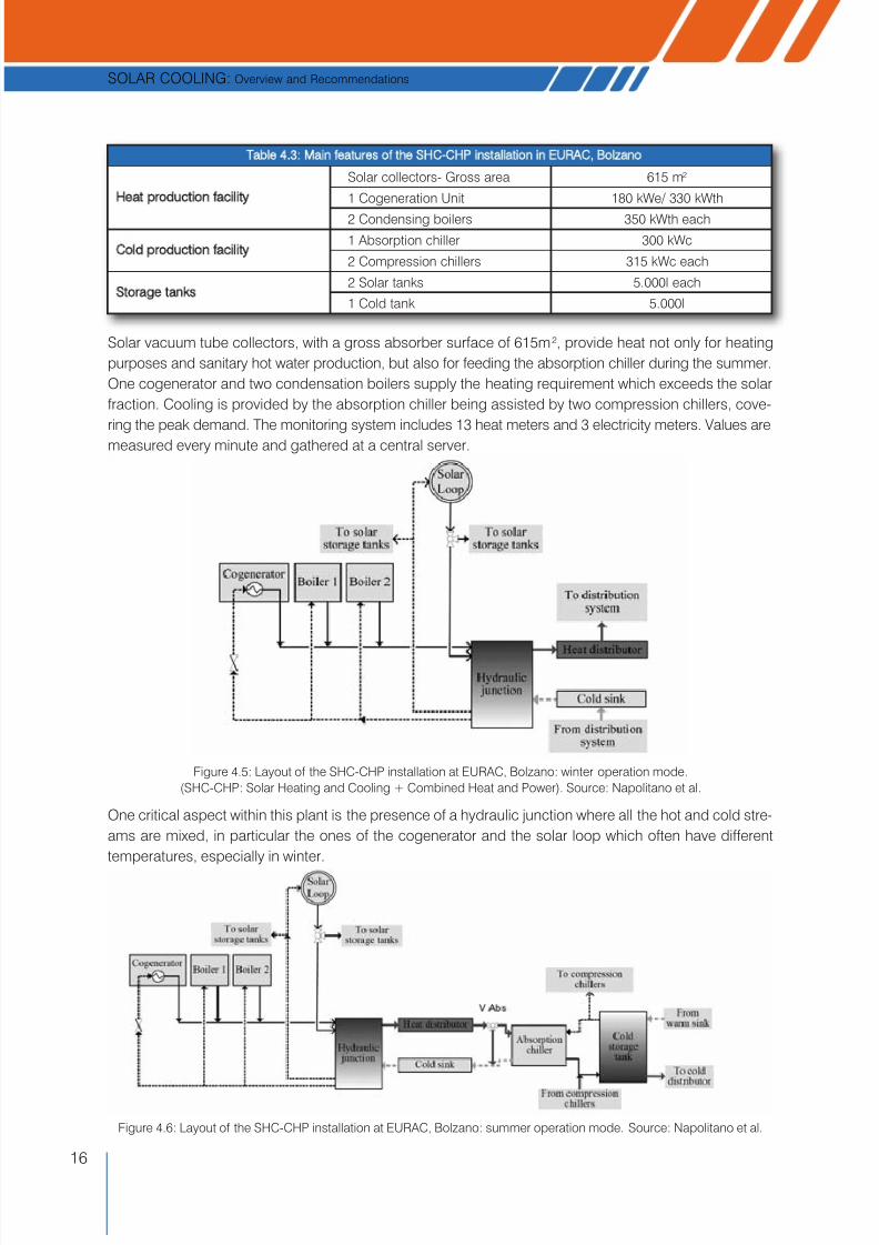
Figure 4.6: Layout of the SHC-CHP installation at EURAC, Bolzano: summer operation mode. Source: Napolitano et al.
Solar vacuum tube collectors, with a gross absorber surface of 615m 2, provide heat not only for heating
purposes and sanitary hot water production, but also for feeding the absorption chiller during the summer.
One cogenerator and two condensation boilers supply the heating requirement which exceeds the solar
fraction. Cooling is provided by the absorption chiller being assisted by two compression chillers, cove-
ring the peak demand. The monitoring system includes 13 heat meters and 3 electricity meters. Values are
measured every minute and gathered at a central server.
One critical aspect within this plant is the presence of a hydraulic junction where all the hot and cold stre-
ams are mixed, in particular the ones of the cogenerator and the solar loop which often have different
temperatures, especially in winter.
Figure 4.5: Layout of the SHC-CHP installation at EURAC, Bolzano: winter operation mode.(SHC-CHP: Solar Heating and Cooling + Combined Heat and Power). Source: Napolitano et al.

7/29/2019 Solco Technical Final
http://slidepdf.com/reader/full/solco-technical-final 19/28
17
SOLAR COOLING: Overview and Recommendations
Figure 4.7: Solar vacuum tube collectors installed on EURAC roof
The monitoring system has demonstrated that the control strategy influences the performance of the sin-
gle devices, in particular of the solar collectors, the cogeneration unit and the absorption chiller.
4.4 N. Kazantzakis town hall, Heraklion, CreteThis is a town hall building consisting of a basement, a ground floor and one storey with total surface of 2.500m².
The building’s profile was developed through the SimCad software (fig. 4.8). Initially the heating and cooling
loads were estimated and presented on a monthly basis through a 12-month period (fig.4.9).
The suggested solar cooling system consists of 300m² of flat plate selective collectors titled 15° from the
horizontal, a 20m³ hot water storage tank, a 125kW nominal power absorption chiller (LiBr-H2O), a 35kW
nominal power compression chiller, a 130kW oil back up heat source and a 250kW nominal power coo-
ling tower.
Figure 4.8: Building profile and thermal zones definition Figure 4.9: Heating & cooling loads on monthly base
The basic assumptions made during the economic evaluation were:
• Maintenance costs: conventional: 2% of investment costs, solar: 1% of investment costs
• Operating costs associated with the solar process include the cost of electricity for the pumps opera-
tion, interest charges on funds borrowed to purchase the equipment and other
• Installation costs: 12% of the equipment cost
• The energy inflation is taken equal to 2%
• Energy prices: electricity: 0,18 € /kWh, oil: 600 € /t (2007)
Several technical features and the equipment cost are presented in table 4.4.
Energy demands on heating
Energy demands on cooling
Jan Feb Mar Apr May Jun Jul Aug Sep Oct Nov DecMonth
E
g
kW/h
25.000
20.000
15.000
10.000
5.000
0

7/29/2019 Solco Technical Final
http://slidepdf.com/reader/full/solco-technical-final 20/28
18
SOLAR COOLING: Overview and Recommendations
Table 4.4: Technical features and the cost of equipment
Equipment Cost
FPC selective 466 € (2,6m²)
Absorption Chiller LiBr-H2O (COP=0,7) 400 € /kWConventional chiller (COP=2,5) 310 € /kW
Back up heat source (n=85%) 50 € /kW
Environmental and Economic Data: The total investment cost was estimated to be 163.352 € and the total
annual operating cost: 4.109 €. The payback time was also calculated equal to 18,5 years. The solar frac-
tion was estimated at 87,8%. Finally, the overall primary energy savings was estimated at 87.944kWh and
the total CO2
savings at 32.337kg.
4.5 General Hospital of Sitia, CreteThe building is part of the facilities of the General Hospital of Sitia. Building Β has an overall surface of
1.250m2 and consists of 3 areas. It accommodates the maternity clinic on the ground floor, the cardiology
and the pathology clinic on the first floor and the paediatrics clinic on the second floor. This building was
selected mainly for three reasons: the high importance that the General Hospital attributes to management,
the problems in the existing conventional AC system, and its operation as a clinic.
Figure 4.10: General Hospital of Sitia Figure 4.11: Profile of the building created in SimCad
The annual required energy of heating is 34.205kWh and the annual required energy of cooling is 123.911kWh.
The suggested system consists of 500m² flat plate selective collectors tilted 15° from the horizontal, a
15m³ hot water storage tank, 70kW nominal power of absorption chiller (LiBr-H2O), 50kW nominal power
of compression chiller, 87kW oil back up heat source and 170 kW nominal power cooling tower.
Environmental and Economic Data: The assumptions made during the economic evaluation were almost
the same with the previous case. Only two parameters concerning energy prices were changed: electri-
city: 0,25 € /kWh and oil: 1.200 € /t (2008). The total investment cost without funding subsidies is 173.992 €
and the total annual operating cost: 6.473 €. The payback time was also calculated equal to 11,5 years.
The solar fraction was estimated at 74,73%. Finally, the overall primary energy savings was estimated
113.581kWh and the total CO2
savings at 45.535kg.
Note: Case studies 5.4 and 5.5 have been designed by the Renewable and Sustainable Energy Systems
Laboratory, Environmental Engineering Department, Technical University of Crete.

7/29/2019 Solco Technical Final
http://slidepdf.com/reader/full/solco-technical-final 21/28
19
SOLAR COOLING: Overview and Recommendations
Nowadays solar cooling technologies are neither as well known, nor as widespread as they should be.
They have not yet enjoyed a significant level of penetration into the air conditioning market in Southern
Europe. One of the main objectives of the SOLCO project is to identify the non-technical barriers pre-
venting further penetration of solar cooling technologies. This section identifies these barriers and pro-
poses ways to overcome them.
5.1 Barriers for the wide adoption of solar cooling technologiesDuring the implementation of the SOLCO project a number of market barriers was identified and verified,
such as:
(i) Awareness and know-how
• Lack of awareness in potential users (hotels, hospitals, and others) about the possibilities and bene-
fits of using solar driven cooling plants;
• Most of the technical actors are not familiar with SC technologies, and they do not suggest them as a
solution to potential users;• Most engineers are not completly educated in this technology;
• The suppliers of the plants are mainly engineering consultants and installers; they need additional sup-
port through training, design tools (software) and control systems in order to do their job better;
• Lack of packaged solutions is a serious problem not only during setting-up but also during the life of
the installation (maintenance); the installation and M&O need specific knowhow;
(ii) Demonstration
• A rather limited number of demonstration plants; by the end of 2007 there were approximately 300
Solar Cooling systems in operation worldwide; only a few of them are monitored and as a result there
is limited information about their performance;
(iii) Cost
• Relevant market actors claim that the high investment cost limits widespread application;
• Today’s sorption technologies are, still, more expensive in comparison to conventional chillers; this is
more evident in the case of small scale sorption chillers (residential, small trade centers etc). Signifi-
cant effort is required to develop the existing technology in order to reduce the cost of system:
• The use of sorption chillers requires in most cases the existence of wet cooling towers, which are cov-
ered by specific legislation to avoid the legionnaire’s disease. The maintenance of such installations is
more expensive and most of the potential users prefer to avoid them;
(iv) Market availability
• Although there is an important increase in the size of this market, today there is limited or no market
availability of small capacity systems;
Barriers and
Recommendations5

7/29/2019 Solco Technical Final
http://slidepdf.com/reader/full/solco-technical-final 22/28
20
SOLAR COOLING: Overview and Recommendations
(v) Policy and incentives
• Tax exemptions and other financial incentives for solar thermal systems are limited and clearly not suf-
ficient to promote the technology;
• A roadmap for solar-assisted cooling systems at national and/or European levels is missing; theseinstallations are often forgotten in today’s financial incentive schemes for solar thermal plants.
5.2 Recommendations to overcome the barriersDespite the fact that the adoption of solar technologies is recognized as a realistic response to the ener-
gy and environmental problems that are attracting the attention of the public, economic evaluations are
often unfavourable. Critical factors that will ensure the spreading of solar cooling systems are techno-
logical maturity and improved economic viability.
Economic analyses of solar cooling systems indicate that these systems will not be competitive com-
pared with standard cooling systems at present energy prices. There is a strong need both for investment
incentives and a fair environmental tax to reflect the full environmental costs of conventional fuels.
In order to overcome the multitude of obstacles and barriers faced by the solar cooling technologies the
project partners identified the following remedial actions:
(i) Information-dissemination
• Develop a strong Europe-wide campaign of the SC technology to create broad awareness and new
and better market implementation activities to decision makers and potential users;
(ii) Demonstration
• A large number of demonstration projects is necessary and overall, real data about the performance
of monitored plants is absolutely necessary. The existing solar cooling installations show a high cost
reduction potential for the next generation of cooling plants;
(iii) Training
• As indicated by the extensive training activities carried out during the life of the SOLCO project, spe-
cific training courses for professionals (installers) and inclusion of solar cooling technologies into stan-
dard education for engineers is a must; development of advanced modelling and simulation tools for
designers and installers is also absolutely necessary;
(iv) Quality, O&M
• Improvement of components with respect to their performance (increasing the COP in the case of
chillers and the efficiency of solar collectors) is also required; at the same time this improvement must
reduce the cost of the components in order to make solar driven cooling plants more attractive;
• Standardisation in the field of solar driven cooling plants, design guidelines, proven operation and
maintenance concepts is necessary;
(v) Policy
• Introduction of legislation that requires Member States to keep statistics on energy demand for cool-
ing purposes;
• Inclusion of solar cooling into financial incentive schemes and subsidies for solar thermal at national
and European level;
• There is still a need for subsidies to support the implementation of solar cooling technologies in order
to ensure their effective penetration into the cooling market;
• Establishment of an accreditation process based on specific training together with a good track record
of successful installations and client references.

7/29/2019 Solco Technical Final
http://slidepdf.com/reader/full/solco-technical-final 23/28
21
SOLAR COOLING: Overview and Recommendations
Further to the barriers identified in the previous section, the higher investment costs -required for solar
cooling installations- need a very careful analysis of the economic and the financial aspects of the project.
This analysis has to start with a feasibility study that will seek to establish the technological, financial and
environmental viability of the project. Once there is enough evidence that the project is feasible, a more
detailed financial analysis has to be carried out, in order to establish the financial structure of the projectand identify all available sources of financing.
6.1 Feasibility studyThere is a need for a new perspective in valuing solar energy technologies. The need for new economic
cost perspectives derives from the fact that these technologies have vastly divergent financial risk char-
acteristics; additionally the unpredictability of conventional fuel prices over long periods should be taken
into account.
The first crucial steps in developing a solar cooling project are to ensure
that it can be realised from a technological, financial and environmentalpoint of view. Before the actual commitment to implementation, most proj-
ects have to undergo a detailed feasibility assessment.
A feasibility study should include a technical evaluation of all potential alter-
natives. It should also contain a concrete summary of the financial aspects;
a reliable feasibility study is a valuable tool in order to identify and attract the
financing resources needed for a successful project implementation. After
a pre-screening of preferred and alternative options, there is a need for a
comparison of the alternative solutions against quality and quantity issues,
land costs, local social, environmental and economic impacts, necessary
permits, profitability etc.Conducting the feasibility study, the following steps - as presented in fig-
ure 6.1 - should be followed.
Background information: This step summarises the motivation for carrying
out the project, as well as the rationale on how this project fits within the sus-
tainable energy strategy of the community. A general description is an addi-
tional required task. This step also identifies project objectives and incorpo-
rates fundamental information about facility size and design considerations.
Technology choice: This step focuses on the recommended technology;
how it would fit with the existing facility, what benefits the system would pro-
vide and how these benefits would be exploited. It would also outline and
compare with alternative options that could be used instead. It is important
1.Background information
2.Technology choice
3.Financial analysis
4.Weaknesses
5 Conclusions andrecommendations
Figure 6.1: Steps in the
Feasibility Study
Economic & Financial
Considerations6

7/29/2019 Solco Technical Final
http://slidepdf.com/reader/full/solco-technical-final 24/28
22
SOLAR COOLING: Overview and Recommendations
to develop the most suitable project that best fits the vision, needs, and current conditions. An initial
screening of the financial, environmental and social costs, as well as the benefits coming from alternative
energy technologies is recommended in this stage.
Financial analysis evaluates the system’s costs and illustrates how the owner would pay for it. This stepshould also include a cost effectiveness evaluation that would detail social, environmental, and avoided
cost benefits in addition to the simple payback period calculation.
Weaknesses: This step concentrates on the identification of major problems, obstacles and prospective
barriers concerning the project. It should also suggest solutions and provide recommendations on how
to address these issues.
Conclusions and Recommendations:This final step of the feasibility study offers the main conclusions
and judgments regarding whether or not the project should proceed.
6.2 Funding Opportunities and Financing InstrumentsFinancing for solar cooling projects can come from multiple sources, including up-front equity, debt
financing, incentives schemes (including subsidies, low-interest loans, grants and tax incentives). A brief
overview of the most common available types of funding follows:
• Equity Financing: For private companies or Public-Private-Partnerships developing solar projects, it is
important that they have a sound financial structure. No granting agency or financial institution will pro-
ceed with the approval of grants or debt financing if the owners are not willing to risk their own capital in
the project. It is therefore essential that in preparing the financial structure, and before any application for
external financing, the owners establish their own equity by creating an appropriate equity capital struc-
ture that will provide the basis for further financing from outside sources, such as banks, government
agencies and other lending institutions.
• Debt Financing: Even if a project receives public funding, some of the funds should probably comefrom financial institutions through debt financing. Before visiting the banks, project developers should
prepare the project’s plan and feasibility study, and gather all available site and financial data presented
in a comprehensive “proposal to finance”. In cases where the project objectives include selling power to
the local utility, it is necessary to conclude a power purchase agreement with the utility; this will help the
bank assess the financial viability of the project and evaluate the potential payback period.
• Governmental Incentive Payments: These may appear in the form of direct or indirect subsidies, tax
incentives, low VAT rates, energy tax exemptions, public subsidies for environmental investments, or as
production payments. Eligibility and availability of incentive schemes are frequently subject to change, so
any project that relies on incentive payments should verify that the incentives under consideration are still
available at the project’s inception.• Public (European and National) Loans and Grants: Beyond production incentives, there may exist loan
or grant programmes available to help finance renewable energy projects. Schools, social houses, munic-
ipalities and other government units may be eligible for Community Support Framework (CSF) funding.
• EU grants: They provide funding opportunities and are awarded to co-finance specific projects or objec-
tives, usually through calls for proposals. EU grants cover a whole range of EU policy areas for sustainable,
competitive and secure energy and environmental protection, such as: electricity production from RES, RES
share in energy mix, energy efficiency etc. The form of application depends on the type of funding:
• structural funds are managed at national or regional level and, as a result, applications are sub-
mitted to and evaluated by national or regional authorities;
• for EU grants, application procedures are set out in the calls for proposals for specific pro-grammes, and applications are sent directly to the European Commission or an executive agency
which runs the programme in question.

7/29/2019 Solco Technical Final
http://slidepdf.com/reader/full/solco-technical-final 25/28
23
SOLAR COOLING: Overview and Recommendations
Table 6.1 illustrates the main EU financing instruments, which could benefit a solar cooling project:
6.3 EU legislation and policyThe following table provides an indicative list of the European Union legislative and supporting initiatives
that foster the increase of RES share in electricity and the efficiency of energy use, encouraging the
reduction of total energy consumption, at national, regional and local level.
Table 6.2: Indicative list of the current EU policy, legislative and supporting initiatives• New Directive on the promotion of the use of energy from renewable sources (COM(2008)19 final)
• Energy for a Changing World - An Energy Policy for Europe, (COM(2007)1 final)
• Integrated energy and climate change package (COM(2007)1 final) and the Presidency Conclusions
of the Brussels European Council (8/9 March 2007)
• Green Paper follow-up action - Report on progress in renewable electricity (COM(2006)849 final)
• Renewable Energy Road Map - Renewable energies in the 21st century: building a more sustainable
future (COM(2006)848 final)
• Towards a European Strategic Energy Technology Plan (COM(2006)847 final)
• Green Paper - A European Strategy for Sustainable, Competitive and Secure Energy (COM(2006)105 final
• Directive on the energy performance of buildings (2002/91/EC)
• Renewable Electricity Directive (2001/77/EC)
• Green paper on security of energy supply (COM(2000)769)
• White Paper on Renewable Energy Sources (COM(97)599 final)
More information for European legislation currently in force or in preparation can be found or downloaded
from EUR-Lex, the portal to European Union law. EUR-Lex provides direct free access to European Union
law, in all official languages; http://eur-lex.europa.eu.
Copies of the above documents can be also downloaded from the following websites:
• http://ec.europa.eu/energy/energy_policy/index_en.htm (energy and climate change package)
• http://ec.europa.eu/energy/res/legislation/index_en.htm (renewable related legislation)• http://ec.europa.eu/energy/demand/legislation/index_en.htm (energy efficiency related legislation)
• http://europa.eu.int/eur-lex/en/lif/ind/en_analytical_index_07.html
Table 6.1: Main EU financing instruments
1. Framework Programme - CIP (2007-2013) Competitiveness and Innovation
http://ec.europa.eu/cip1.1. Intelligent Energy - Europe Programme 2007-2013
http://ec.europa.eu/energy/intelligent/call_for_proposals/index_en.htm
1.2. LIFE + (2007-2013)
http://ec.europa.eu/environment/life/funding/lifeplus.htm
1.3. Marco Polo Programme (2003-2010)
http://ec.europa.eu/transport/marcopolo/index_en.htm
2. Seventh Framework Programme - FP7 (2007 to 2013)
http://ec.europa.eu/research/fp7, http://www.cordis.lu/fp7
3. EU Structural Funds
http://www.eugrants.org/frametemplate.html3.1. European Regional Development Fund - ERDF
http://ec.europa.eu/regional_policy/funds/feder/index_en.htm
3.2. European Agricultural Fund for Rural Development - EAFRD 2007-2013
http://ec.europa.eu/agriculture/rurdev/index_en.htm

7/29/2019 Solco Technical Final
http://slidepdf.com/reader/full/solco-technical-final 26/28
24
SOLAR COOLING: Overview and Recommendations
Nowadays, Solar Cooling is both possible and reli-
able. Exploitation of solar thermal energy for cool-
ing is an efficient, intelligent and environmentally
friendly way to use renewable energy sources to
meet our air conditioning needs.
However, applications of solar cooling are actual-
ly too few. This is both the cause and the result of
the low levels of penetration of this technology,
even in markets where solar radiation is relatively
high, namely those of Southern Europe.
SOLCO is reporting the following major findings in
the diffusion of solar cooling technologies:
• At local level there is a real need for the imple-
mentation of solar cooling and the public is will-
ing to use the technology for air conditioning
applications in the residential, commercial and
public sector, including private enterprises,
hotels and hospitals.
• The investment cost of solar cooling installa-
tions is higher than conventional air condition-
ing systems. As a result, relatively few installa-
tions are in place and this in turn keeps the cost
of components (such as chillers) relatively highdue to the absence of economies of scale.
• There is a lack of widespread specialised
knowledge of solar cooling technologies
amongst designers, installers and maintainers
who in their majority continue to design and pro-
mote conventional non-solar installations.
In order to overcome existing non-technical bar-
riers and improve the penetration of SC tech-
nologies in the European market, SOLCO’s main
recommendations are:
• Training of technical market actors (designers,
installers, maintainers) is crucial in order to
overcome the knowledge barrier.
• Financial support schemes at national and
European level are essential in order to over-come the financial barrier and make SC tech-
nologies competitive, improve market penetra-
tion and exploit economies of scale. These
schemes can be in the form of grants, sub-
sidised interest rate loans, and/or tax incentives.
• Dissemination of information on the advantages
of solar cooling is vital. A Europe-wide cam-
paign, with emphasis in Southern Europe, is
central in order to improve the understanding
and acceptance of solar cooling technologiesby the general public.
Conclusions7

7/29/2019 Solco Technical Final
http://slidepdf.com/reader/full/solco-technical-final 27/28
$$!%
E 38,/?78009$01<420<,>4:9,9/4<:9/4>4:9492#?-74=30/-C#0,<9492#@>>/%!
E <24<4:?G%:7,<.::7492.:?<=0H'94@0<=4>C:1#,><,=0;>:1#3C=4.=%0.>4:9:1,;;740/;3C=4.=
E ,7,<,=<:==8,909949291,9>00<<04<,#:/0==0<),92)408609G%:7,<,4<.:9/4>4:949249?<:;0,9
:@0<@40AH$090A,-70,9/%?=>,49,-7090<2C$0@40A=(:7?80==?00-<?,<C;;
E 7=8,<&G$>=071=?114.409><090A,-70090<2C,4<.:9/4>4:9492=C=>081:<0/4>0<<,90,9.:?9><40=H 0=,749,>4:9
;;F
E !,;:74>,9:<,9.3494!?<D4,%;,<-0<)G:?;7492%:7,<.:770.>:<=,9/.:2090<,>4:9?94>=49=:7,<,==4=>0/30,>492
,9/.::7492=C=>08=H'$"%'!=>
9>0<9,>4:9,7:910<09.0:9%:7,<0,>492::7492,9/?47/492=4=-:9".>:-0<
E #,;,/:;:?7:="B4D4/4=%C<4,64=!G#0<=;0.>4@0=:1=:7,<.::749249@40A:1>30/0@07:;809>=49>30,4<.:9/4>4:9492=0.>:<H
$090A,-70,9/%?=>,49,-7090<2C$0@40A=(:7?80==?0".>:-0<;;
E #<4/,=,A,=)&0.708,<4,8!08,<4,8G%:7,<.::7492.:?<=0H&90<24>06946
E &=431>0=G%:7,<.::7492,9/90A,;;74.,>4:9=H%:7,<.::7492=0849,< ,9/!0A;;74.,>4:9=&0.394.,73,8-0<:1C;<?=
E &=:?>=:=&9,29:=>:?#<4>.3,</,<,24:<2,=2:<4=G%:7,<::7492&0.39:7:240=49<00.0H;;740/&30<8,7
924900<492
E &=:?>=:=&6:?=6:=+7:?8-4G;;74.,>4:9:1=:7,<.::749249<0>0H?47/492<0090.08-0<
E @,<4:?=748,=:7;<:50.>7>0<90<;<:2<,880<,00:<2.748,>4=,>4:9=:7,4<02-/:.?809>=3>8
E +4/4,9,64=&=:?>=:=&+:2<,1,64=!G%48?7,>4:9:1 ,=:7,<,-=:<;>4:9.::7492=C=>08H9/ #!:910<09.0<0>0
<00.0

7/29/2019 Solco Technical Final
http://slidepdf.com/reader/full/solco-technical-final 28/28
"(1!)+(+"1((/$+)('(-+)/$()!"+$"(-)$$&1000*$-
(+1,&(,(,-$-.-)!#()&)"1000$-(+$,)+"
1*+.,(,-$-.-)!(+"1000$)+"1
.+)*(,&(,-0)+%)((+"1
((/$+)('(-000$,&(-(-
#($&($/+,$-1)!+-2(/$+)('(-&("$(+$("*+-'(-(0&(.,-$(&(+"11,-',000(/("-."+
.**)+-1
+).1)'#$+&(($&($+#.-++$,)!)-&((0$%)-)+()01,&)!0$,
#--*000$,&(-(-$,&(-,%1(-