Solar SpO Module with Masimo SETinterest Module with Masimo SET® Service Manual ... Monarch 8000,...
58
Solar ® SpO 2 Module with Masimo SET ® Service Manual 2004407-001 Revision A
Transcript of Solar SpO Module with Masimo SETinterest Module with Masimo SET® Service Manual ... Monarch 8000,...
Solar® SpO2 Module with Masimo SET®
Service Manual
2004407-001 Revision A
127(��Due to continuing product innovation, specifications in this manual are subject to change without notice.
Listed below are GE Medical Systems Information Technologies trademarks. All other trademarks contained herein are the property of their respective owners.
900 SC, ACCUSKETCH, AccuVision, APEX, AQUA-KNOT, ARCHIVIST, Autoseq, BABY MAC, C Qwik Connect, CardioServ, CardioSmart, CardioSys, CardioWindow, CASE, CD TELEMETRY, CENTRA, CHART GUARD, CINE 35, CORO, COROLAN, COROMETRICS, Corometrics Sensor Tip, CRG PLUS, DASH, Digistore, Digital DATAQ, E for M, EAGLE, Event-Link, FMS 101B, FMS 111, HELLIGE, IMAGE STORE, INTELLIMOTION, IQA, LASER SXP, MAC, MAC-LAB, MACTRODE, MANAGED USE, MARQUETTE, MARQUETTE MAC, MARQUETTE MEDICAL SYSTEMS, MARQUETTE UNITY NETWORK, MARS, MAX, MEDITEL, MEI, MEI in the circle logo, MEMOPORT, MEMOPORT C, MINISTORE, MINNOWS, Monarch 8000, MULTI-LINK, MULTISCRIPTOR, MUSE, MUSE CV, Neo-Trak, NEUROSCRIPT, OnlineABG, OXYMONITOR, Pres-R-Cuff, PRESSURE-SCRIBE, QMI, QS, Quantitative Medicine, Quantitative Sentinel, RAC RAMS, RSVP, SAM, SEER, SILVERTRACE, SOLAR, SOLARVIEW, Spectra 400, Spectra-Overview, Spectra-Tel, ST GUARD, TRAM, TRAM-NET, TRAM-RAC, TRAMSCOPE, TRIM KNOB, Trimline, UNION STATION, UNITY logo, UNITY NETWORK, Vari-X, Vari-X Cardiomatic, VariCath, VARIDEX, VAS, and Vision Care Filter are trademarks of GE Medical Systems Information Technologies registered in the United States Patent and Trademark Office.
12SL, 15SL, Access, AccuSpeak, ADVANTAGE, BAM, BODYTRODE, Cardiomatic, CardioSpeak, CD TELEMETRY®-LAN, CENTRALSCOPE, Corolation, EDIC, EK-Pro, Event-Link Cirrus, Event-Link Cumulus, Event-Link Nimbus, HI-RES, ICMMS, IMAGE VAULT, IMPACT.wf, INTER-LEAD, IQA, LIFEWATCH, Managed Use, MARQUETTE PRISM, MARQUETTE® RESPONDER, MENTOR, MicroSmart, MMS, MRT, MUSE CardioWindow, NST PRO, NAUTILUS, O2SENSOR, Octanet, OMRS, PHi-Res, Premium, Prism, QUIK CONNECT V, QUICK CONNECT, QT Guard, SMART-PAC, SMARTLOOK, Spiral Lok, Sweetheart, UNITY, Universal, Waterfall, and Walkmom are trademarks of GE Medical Systems Information Technologies.
© GE Medical Systems Information Technologies, 2000. All rights reserved.
T-2 Masimo SET SpO2 Module Revision A2004407-001 15 December 2000
Contents
1 Introduction . . . . . . . . . . . . . . . . . . . . . . . . . . . . . . . . . . . . 1-1Manual Information . . . . . . . . . . . . . . . . . . . . . . . . . . . . . . . . . . . . . . . . . . . . . . . . . . 1-3
Revision History . . . . . . . . . . . . . . . . . . . . . . . . . . . . . . . . . . . . . . . . . . . . . . . . . . . 1-3Purpose . . . . . . . . . . . . . . . . . . . . . . . . . . . . . . . . . . . . . . . . . . . . . . . . . . . . . . . . . 1-3Intended Audience . . . . . . . . . . . . . . . . . . . . . . . . . . . . . . . . . . . . . . . . . . . . . . . . . 1-3
Safety Information . . . . . . . . . . . . . . . . . . . . . . . . . . . . . . . . . . . . . . . . . . . . . . . . . . . 1-4Responsibility of the Manufacturer . . . . . . . . . . . . . . . . . . . . . . . . . . . . . . . . . . . . . 1-4Intended Use . . . . . . . . . . . . . . . . . . . . . . . . . . . . . . . . . . . . . . . . . . . . . . . . . . . . . 1-4Definitions of Warnings, Cautions, and Notes . . . . . . . . . . . . . . . . . . . . . . . . . . . . 1-5Equipment Symbols . . . . . . . . . . . . . . . . . . . . . . . . . . . . . . . . . . . . . . . . . . . . . . . . 1-5
Service Information . . . . . . . . . . . . . . . . . . . . . . . . . . . . . . . . . . . . . . . . . . . . . . . . . . 1-6Service Requirements . . . . . . . . . . . . . . . . . . . . . . . . . . . . . . . . . . . . . . . . . . . . . . 1-6Equipment Identification . . . . . . . . . . . . . . . . . . . . . . . . . . . . . . . . . . . . . . . . . . . . . 1-6
2 Equipment Overview . . . . . . . . . . . . . . . . . . . . . . . . . . . . . 2-1System Components . . . . . . . . . . . . . . . . . . . . . . . . . . . . . . . . . . . . . . . . . . . . . . . . . 2-3
Solar SpO2 Module with Masimo SET . . . . . . . . . . . . . . . . . . . . . . . . . . . . . . . . . . 2-3Solar 7000 Patient Monitor . . . . . . . . . . . . . . . . . . . . . . . . . . . . . . . . . . . . . . . . . . 2-4Solar 8000 Patient Monitor . . . . . . . . . . . . . . . . . . . . . . . . . . . . . . . . . . . . . . . . . . 2-4Solar 8000M Patient Monitor . . . . . . . . . . . . . . . . . . . . . . . . . . . . . . . . . . . . . . . . . 2-5Tram-rac Housing . . . . . . . . . . . . . . . . . . . . . . . . . . . . . . . . . . . . . . . . . . . . . . . . . 2-5
Technical Specifications . . . . . . . . . . . . . . . . . . . . . . . . . . . . . . . . . . . . . . . . . . . . . . 2-6
Insert Module . . . . . . . . . . . . . . . . . . . . . . . . . . . . . . . . . . . . . . . . . . . . . . . . . . . . . . . 2-8
Revision A Solar SpO2 with Masimo SET i2004407-001
3 Maintenance . . . . . . . . . . . . . . . . . . . . . . . . . . . . . . . . . . . 3-1Maintenance Schedule . . . . . . . . . . . . . . . . . . . . . . . . . . . . . . . . . . . . . . . . . . . . . . . 3-3
Recommended Maintenance . . . . . . . . . . . . . . . . . . . . . . . . . . . . . . . . . . . . . . . . . 3-3Recommended Frequency . . . . . . . . . . . . . . . . . . . . . . . . . . . . . . . . . . . . . . . . . . . 3-3Safety Tests . . . . . . . . . . . . . . . . . . . . . . . . . . . . . . . . . . . . . . . . . . . . . . . . . . . . . . 3-3
Inspection and Cleaning . . . . . . . . . . . . . . . . . . . . . . . . . . . . . . . . . . . . . . . . . . . . . . 3-4Visual Inspection . . . . . . . . . . . . . . . . . . . . . . . . . . . . . . . . . . . . . . . . . . . . . . . . . . 3-4Cleaning Precautions . . . . . . . . . . . . . . . . . . . . . . . . . . . . . . . . . . . . . . . . . . . . . . . 3-4Exterior Cleaning . . . . . . . . . . . . . . . . . . . . . . . . . . . . . . . . . . . . . . . . . . . . . . . . . . 3-4
Checkout Procedure . . . . . . . . . . . . . . . . . . . . . . . . . . . . . . . . . . . . . . . . . . . . . . . . . 3-5General . . . . . . . . . . . . . . . . . . . . . . . . . . . . . . . . . . . . . . . . . . . . . . . . . . . . . . . . . 3-5Required Tools/ Equipment . . . . . . . . . . . . . . . . . . . . . . . . . . . . . . . . . . . . . . . . . . 3-5Preparation . . . . . . . . . . . . . . . . . . . . . . . . . . . . . . . . . . . . . . . . . . . . . . . . . . . . . . 3-6SpO2 Test . . . . . . . . . . . . . . . . . . . . . . . . . . . . . . . . . . . . . . . . . . . . . . . . . . . . . . . 3-6
Electrical Safety Tests . . . . . . . . . . . . . . . . . . . . . . . . . . . . . . . . . . . . . . . . . . . . . . . . 3-8Recommendations . . . . . . . . . . . . . . . . . . . . . . . . . . . . . . . . . . . . . . . . . . . . . . . . . 3-8
Required Tests . . . . . . . . . . . . . . . . . . . . . . . . . . . . . . . . . . . . . . . . . . . . . . . . 3-8Test Conditions . . . . . . . . . . . . . . . . . . . . . . . . . . . . . . . . . . . . . . . . . . . . . . . 3-8
AC Hi-Pot Test . . . . . . . . . . . . . . . . . . . . . . . . . . . . . . . . . . . . . . . . . . . . . . . . . . . . 3-9Test Frequency . . . . . . . . . . . . . . . . . . . . . . . . . . . . . . . . . . . . . . . . . . . . . . . 3-9Required Tools/Equipment . . . . . . . . . . . . . . . . . . . . . . . . . . . . . . . . . . . . . . 3-9Procedures . . . . . . . . . . . . . . . . . . . . . . . . . . . . . . . . . . . . . . . . . . . . . . . . . . . 3-9
Current Leakage Tests . . . . . . . . . . . . . . . . . . . . . . . . . . . . . . . . . . . . . . . . . . . . 3-10Preparation . . . . . . . . . . . . . . . . . . . . . . . . . . . . . . . . . . . . . . . . . . . . . . . . . 3-10Patient (Source) Leakage Current Test . . . . . . . . . . . . . . . . . . . . . . . . . . . . 3-11Patient (Sink) Leakage Current Test . . . . . . . . . . . . . . . . . . . . . . . . . . . . . . 3-12Completion . . . . . . . . . . . . . . . . . . . . . . . . . . . . . . . . . . . . . . . . . . . . . . . . . . 3-13
PM Form . . . . . . . . . . . . . . . . . . . . . . . . . . . . . . . . . . . . . . . . . . . . . . . . . . . . . . . . . . 3-13
Repair Log . . . . . . . . . . . . . . . . . . . . . . . . . . . . . . . . . . . . . . . . . . . . . . . . . . . . . . . . 3-14
ii Solar SpO2 with Masimo SET Revision A2004407-001
4 Troubleshooting . . . . . . . . . . . . . . . . . . . . . . . . . . . . . . . . 4-1General Fault Isolation . . . . . . . . . . . . . . . . . . . . . . . . . . . . . . . . . . . . . . . . . . . . . . . 4-3
First Things to Ask . . . . . . . . . . . . . . . . . . . . . . . . . . . . . . . . . . . . . . . . . . . . . . . . . 4-3Visual Inspection . . . . . . . . . . . . . . . . . . . . . . . . . . . . . . . . . . . . . . . . . . . . . . . . . . 4-3
Troubleshooting Procedure . . . . . . . . . . . . . . . . . . . . . . . . . . . . . . . . . . . . . . . . . . . 4-5System OK LED . . . . . . . . . . . . . . . . . . . . . . . . . . . . . . . . . . . . . . . . . . . . . . . . . . . 4-6MS-3 Communications OK LED . . . . . . . . . . . . . . . . . . . . . . . . . . . . . . . . . . . . . . 4-6Isolated Power Supply OK LED . . . . . . . . . . . . . . . . . . . . . . . . . . . . . . . . . . . . . . . 4-6
Theory of Operation . . . . . . . . . . . . . . . . . . . . . . . . . . . . . . . . . . . . . . . . . . . . . . . . . . 4-7Hardware Functions . . . . . . . . . . . . . . . . . . . . . . . . . . . . . . . . . . . . . . . . . . . . . . . . 4-7Software Functions . . . . . . . . . . . . . . . . . . . . . . . . . . . . . . . . . . . . . . . . . . . . . . . . 4-7System Processor . . . . . . . . . . . . . . . . . . . . . . . . . . . . . . . . . . . . . . . . . . . . . . . . . 4-7Masimo MS-3 . . . . . . . . . . . . . . . . . . . . . . . . . . . . . . . . . . . . . . . . . . . . . . . . . . . . . 4-8Host Patient Monitor Communications . . . . . . . . . . . . . . . . . . . . . . . . . . . . . . . . . . 4-9Power Condition and Soft Start . . . . . . . . . . . . . . . . . . . . . . . . . . . . . . . . . . . . . . . 4-9Isolated Power Supply . . . . . . . . . . . . . . . . . . . . . . . . . . . . . . . . . . . . . . . . . . . . . . 4-9Patient Connector Flex Circuit . . . . . . . . . . . . . . . . . . . . . . . . . . . . . . . . . . . . . . . . 4-9
External Connectors . . . . . . . . . . . . . . . . . . . . . . . . . . . . . . . . . . . . . . . . . . . . . . . . 4-10SpO2 Signals . . . . . . . . . . . . . . . . . . . . . . . . . . . . . . . . . . . . . . . . . . . . . . . . . . . . 4-10Probe Schematic Diagram . . . . . . . . . . . . . . . . . . . . . . . . . . . . . . . . . . . . . . . . . . 4-11Host Patient Monitor Connector . . . . . . . . . . . . . . . . . . . . . . . . . . . . . . . . . . . . . . 4-11Software Updates . . . . . . . . . . . . . . . . . . . . . . . . . . . . . . . . . . . . . . . . . . . . . . . . 4-13
5 Parts Lists and Drawings . . . . . . . . . . . . . . . . . . . . . . . . . 5-1Ordering Parts . . . . . . . . . . . . . . . . . . . . . . . . . . . . . . . . . . . . . . . . . . . . . . . . . . . . . . 5-3
General . . . . . . . . . . . . . . . . . . . . . . . . . . . . . . . . . . . . . . . . . . . . . . . . . . . . . . . . . 5-3Field Replaceable Units . . . . . . . . . . . . . . . . . . . . . . . . . . . . . . . . . . . . . . . . . . . . . 5-3
Disassembly Procedures . . . . . . . . . . . . . . . . . . . . . . . . . . . . . . . . . . . . . . . . . . . . . 5-4Assembly Housing . . . . . . . . . . . . . . . . . . . . . . . . . . . . . . . . . . . . . . . . . . . . . . . . . 5-4Masimo SET SpO2 MS-3 PCB . . . . . . . . . . . . . . . . . . . . . . . . . . . . . . . . . . . . . . . . 5-4Masimo SET SpO2 Module Flex PCB . . . . . . . . . . . . . . . . . . . . . . . . . . . . . . . . . . 5-4Masimo SET SpO2 Module PCB . . . . . . . . . . . . . . . . . . . . . . . . . . . . . . . . . . . . . . 5-4Reassembly . . . . . . . . . . . . . . . . . . . . . . . . . . . . . . . . . . . . . . . . . . . . . . . . . . . . . . 5-4Testing . . . . . . . . . . . . . . . . . . . . . . . . . . . . . . . . . . . . . . . . . . . . . . . . . . . . . . . . . . 5-4
Solar SpO2 Module with Masimo SET 2001891-001A . . . . . . . . . . . . . . . . . . . . . . 5-5
Revision A Solar SpO2 with Masimo SET iii2004407-001

iv Solar SpO2 with Masimo SET Revision A2004407-001

1 Introduction
Revision A Solar SpO2 Module with Masimo SET 1-12004407-001

For your notes
1-2 Solar SpO2 Module with Masimo SET Revision A2004407-001

Introduction: Manual Information
Manual Information
Revision History
Each page of the document has the document part number and revision letter at the bottom of the page. The revision letter changes whenever the document is updated.
Purpose
This manual provides technical information for maintaining the equipment. Use it as a guide for maintenance and electrical repair of parts considered field repairable.
Intended Audience
Users of this manual are expected to have a background in electronics, including analog and digital circuitry with RF and microprocessor architectures. It is intended for service representatives and technical personnel who maintain, troubleshoot, or repair this equipment.
Revision Date Comment
A 15 December 2000 Initial release.
Revision A Solar SpO2 Module with Masimo SET 1-32004407-001
Introduction: Safety Information
Safety Information
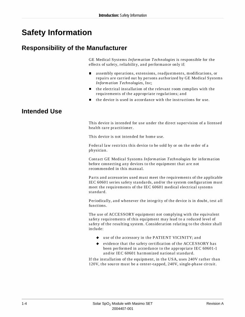
Responsibility of the Manufacturer
GE Medical Systems Information Technologies is responsible for the effects of safety, reliability, and performance only if:
n assembly operations, extensions, readjustments, modifications, or repairs are carried out by persons authorized by GE Medical Systems Information Technologies, Inc;
n the electrical installation of the relevant room complies with the requirements of the appropriate regulations; and
n the device is used in accordance with the instructions for use.
Intended Use
This device is intended for use under the direct supervision of a licensed health care practitioner.
This device is not intended for home use.
Federal law restricts this device to be sold by or on the order of a physician.
Contact GE Medical Systems Information Technologies for information before connecting any devices to the equipment that are not recommended in this manual.
Parts and accessories used must meet the requirements of the applicable IEC 60601 series safety standards, and/or the system configuration must meet the requirements of the IEC 60601 medical electrical systems standard.
Periodically, and whenever the integrity of the device is in doubt, test all functions.
The use of ACCESSORY equipment not complying with the equivalent safety requirements of this equipment may lead to a reduced level of safety of the resulting system. Consideration relating to the choice shall include:
u use of the accessory in the PATIENT VICINITY; andu evidence that the safety certification of the ACCESSORY has
been performed in accordance to the appropriate IEC 60601-1 and/or IEC 60601 harmonized national standard.
If the installation of the equipment, in the USA, uses 240V rather than 120V, the source must be a center-tapped, 240V, single-phase circuit.
1-4 Solar SpO2 Module with Masimo SET Revision A2004407-001
Introduction: Safety Information
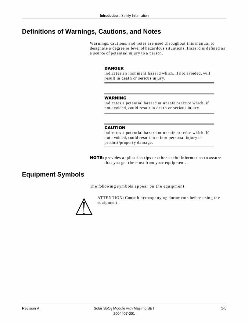
Definitions of Warnings, Cautions, and Notes
Warnings, cautions, and notes are used throughout this manual to designate a degree or level of hazardous situations. Hazard is defined as a source of potential injury to a person.
'$1*(5indicates an imminent hazard which, if not avoided, will result in death or serious injury.
:$51,1*indicates a potential hazard or unsafe practice which, if not avoided, could result in death or serious injury.
&$87,21indicates a potential hazard or unsafe practice which, if not avoided, could result in minor personal injury or product/property damage.
127(��provides application tips or other useful information to assure that you get the most from your equipment.
Equipment Symbols
The following symbols appear on the equipment.
ATTENTION: Consult accompanying documents before using the equipment.
Revision A Solar SpO2 Module with Masimo SET 1-52004407-001
Introduction: Service Information
Service Information
Service Requirements
n Refer equipment servicing to GE Medical Systems Information Technologies authorized service personnel only.
n Any unauthorized attempt to repair equipment under warranty voids that warranty.
n It is the user’s responsibility to report the need for service to GE Medical Systems Information Technologies or to one of their authorized agents.
n Failure on the part of the responsible individual, hospital, or institution using this equipment to implement a satisfactory maintenance schedule may cause undue equipment failure and possible health hazards.
n Regular maintenance, irrespective of usage, is essential to ensure that the equipment will always be functional when required.
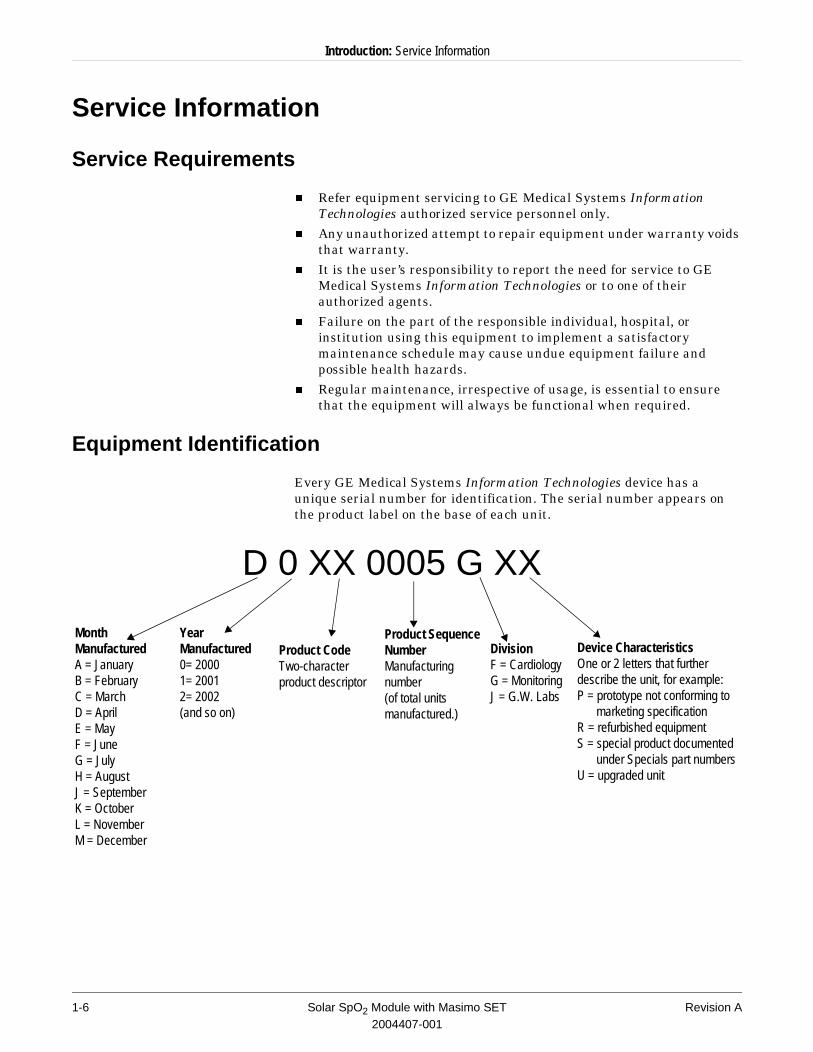
Equipment Identification
Every GE Medical Systems Information Technologies device has a unique serial number for identification. The serial number appears on the product label on the base of each unit.
Month ManufacturedA = JanuaryB = FebruaryC = MarchD = AprilE = MayF = JuneG = JulyH = AugustJ = SeptemberK = OctoberL = NovemberM = December
Year Manufactured0= 20001= 20012= 2002(and so on)
Product CodeTwo-character product descriptor
Product Sequence NumberManufacturing number (of total units manufactured.)
Device CharacteristicsOne or 2 letters that further describe the unit, for example:P = prototype not conforming to
marketing specificationR = refurbished equipmentS = special product documented
under Specials part numbersU = upgraded unit
DivisionF = CardiologyG = MonitoringJ = G.W. Labs
D 0 XX 0005 G XX
1-6 Solar SpO2 Module with Masimo SET Revision A2004407-001
2 Equipment Overview
Revision A Solar SpO2 Module with Masimo SET 2-12004407-001

For your notes
2-2 Solar SpO2 Module with Masimo SET Revision A2004407-001
Equipment Overview: System Components
System Components
Solar SpO2 Module with Masimo SET
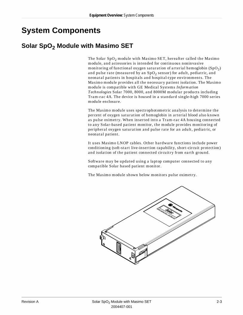
The Solar SpO2 module with Masimo SET, hereafter called the Masimo module, and accessories is intended for continuous noninvasive monitoring of functional oxygen saturation of arterial hemoglobin (SpO2) and pulse rate (measured by an SpO2 sensor) for adult, pediatric, and neonatal patients in hospitals and hospital-type environments. The Masimo module provides all the necessary patient isolation. The Masimo module is compatible with GE Medical Systems Information Technologies Solar 7000, 8000, and 8000M modular products including Tram-rac 4A. The device is housed in a standard single-high 7000 series module enclosure.
The Masimo module uses spectrophotometric analysis to determine the percent of oxygen saturation of hemoglobin in arterial blood also known as pulse oximetry. When inserted into a Tram-rac 4A housing connected to any Solar-based patient monitor, the module provides monitoring of peripheral oxygen saturation and pulse rate for an adult, pediatric, or neonatal patient.
It uses Masimo LNOP cables. Other hardware functions include power conditioning (soft-start live-insertion capability, short-circuit protection) and isolation of the patient connected circuitry from earth ground.
Software may be updated using a laptop computer connected to any compatible Solar based patient monitor.
The Masimo module shown below monitors pulse oximetry.
Revision A Solar SpO2 Module with Masimo SET 2-32004407-001
Equipment Overview: System Components
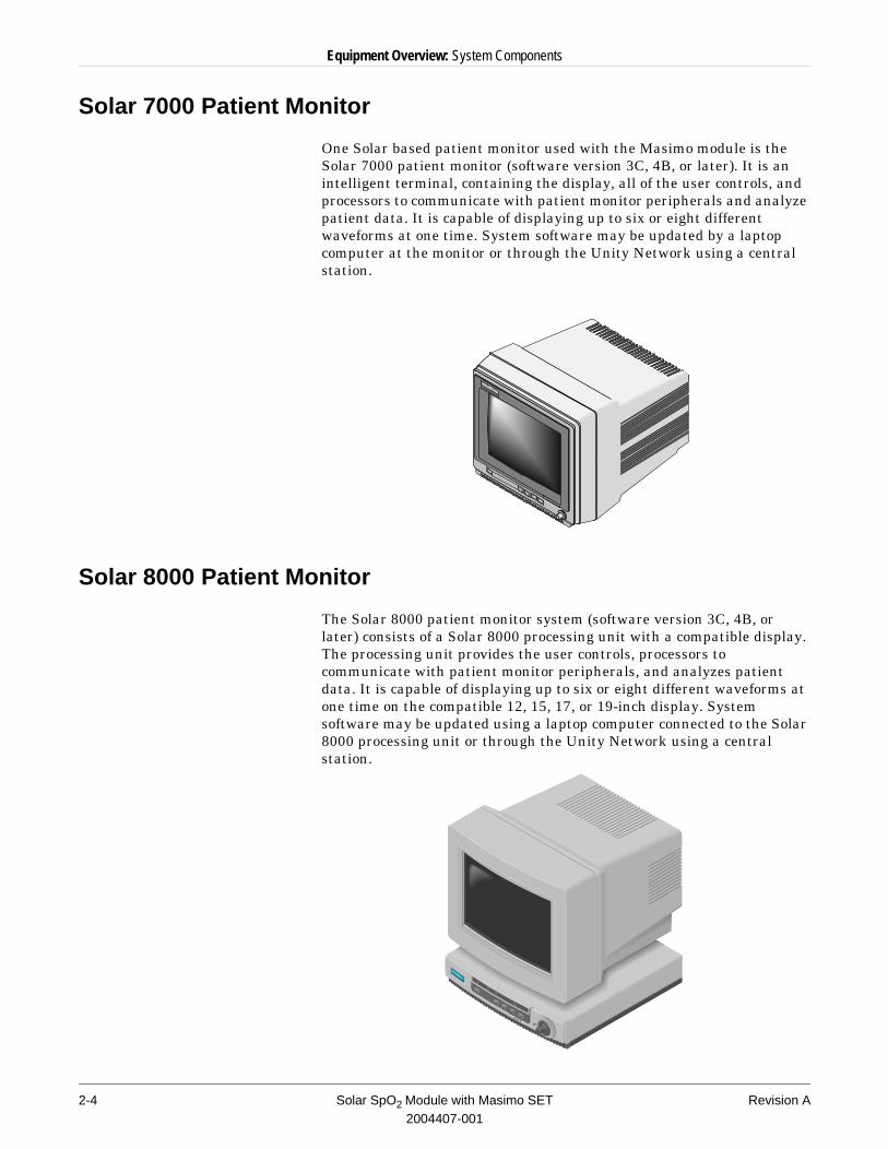
Solar 7000 Patient Monitor
One Solar based patient monitor used with the Masimo module is the Solar 7000 patient monitor (software version 3C, 4B, or later). It is an intelligent terminal, containing the display, all of the user controls, and processors to communicate with patient monitor peripherals and analyze patient data. It is capable of displaying up to six or eight different waveforms at one time. System software may be updated by a laptop computer at the monitor or through the Unity Network using a central station.
Solar 8000 Patient Monitor
The Solar 8000 patient monitor system (software version 3C, 4B, or later) consists of a Solar 8000 processing unit with a compatible display. The processing unit provides the user controls, processors to communicate with patient monitor peripherals, and analyzes patient data. It is capable of displaying up to six or eight different waveforms at one time on the compatible 12, 15, 17, or 19-inch display. System software may be updated using a laptop computer connected to the Solar 8000 processing unit or through the Unity Network using a central station.
Solar 7000
Pat ient Moni tor
2-4 Solar SpO2 Module with Masimo SET Revision A2004407-001
Equipment Overview: System Components
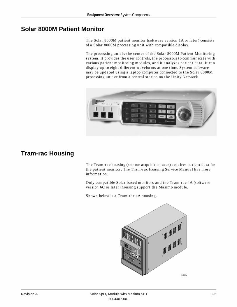
Solar 8000M Patient Monitor
The Solar 8000M patient monitor (software version 1A or later) consists of a Solar 8000M processing unit with compatible display.
The processing unit is the center of the Solar 8000M Patient Monitoring system. It provides the user controls, the processors to communicate with various patient monitoring modules, and it analyzes patient data. It can display up to eight different waveforms at one time. System software may be updated using a laptop computer connected to the Solar 8000M processing unit or from a central station on the Unity Network.
Tram-rac Housing
The Tram-rac housing (remote acquisition case) acquires patient data for the patient monitor. The Tram-rac Housing Service Manual has more information.
Only compatible Solar based monitors and the Tram-rac 4A (software version 6C or later) housing support the Masimo module.
Shown below is a Tram-rac 4A housing.
Revision A Solar SpO2 Module with Masimo SET 2-52004407-001
Equipment Overview: Technical Specifications
Technical Specifications
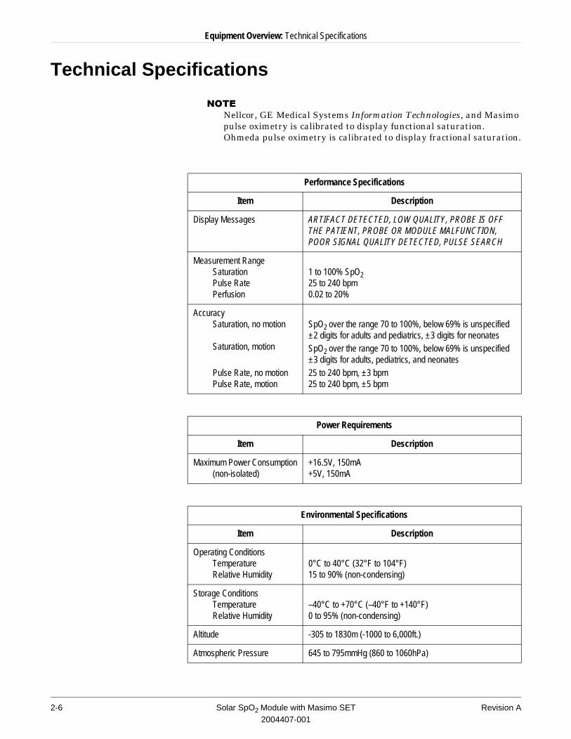
127(�Nellcor, GE Medical Systems Information Technologies, and Masimo pulse oximetry is calibrated to display functional saturation. Ohmeda pulse oximetry is calibrated to display fractional saturation.
Performance Specifications
Item Description
Display Messages ARTIFACT DETECTED, LOW QUALITY, PROBE IS OFF THE PATIENT, PROBE OR MODULE MALFUNCTION, POOR SIGNAL QUALITY DETECTED, PULSE SEARCH
Measurement RangeSaturationPulse RatePerfusion
1 to 100% SpO2 25 to 240 bpm0.02 to 20%
AccuracySaturation, no motion
Saturation, motion
Pulse Rate, no motionPulse Rate, motion
SpO2 over the range 70 to 100%, below 69% is unspecified±2 digits for adults and pediatrics, ±3 digits for neonatesSpO2 over the range 70 to 100%, below 69% is unspecified±3 digits for adults, pediatrics, and neonates25 to 240 bpm, ±3 bpm25 to 240 bpm, ±5 bpm
Power Requirements
Item Description
Maximum Power Consumption(non-isolated)
+16.5V, 150mA+5V, 150mA
Environmental Specifications
Item Description
Operating ConditionsTemperatureRelative Humidity
0°C to 40°C (32°F to 104°F)15 to 90% (non-condensing)
Storage ConditionsTemperatureRelative Humidity
–40°C to +70°C (–40°F to +140°F)0 to 95% (non-condensing)
Altitude -305 to 1830m (-1000 to 6,000ft.)
Atmospheric Pressure 645 to 795mmHg (860 to 1060hPa)
2-6 Solar SpO2 Module with Masimo SET Revision A2004407-001
Equipment Overview: Technical Specifications
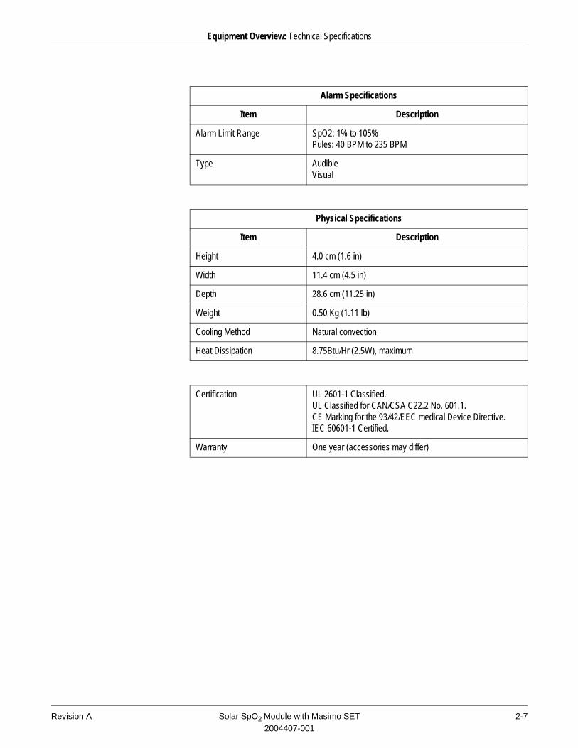
Alarm Specifications
Item Description
Alarm Limit Range SpO2: 1% to 105%Pules: 40 BPM to 235 BPM
Type AudibleVisual
Physical Specifications
Item Description
Height 4.0 cm (1.6 in)
Width 11.4 cm (4.5 in)
Depth 28.6 cm (11.25 in)
Weight 0.50 Kg (1.11 lb)
Cooling Method Natural convection
Heat Dissipation 8.75Btu/Hr (2.5W), maximum
Certification UL 2601-1 Classified. UL Classified for CAN/CSA C22.2 No. 601.1.CE Marking for the 93/42/EEC medical Device Directive.IEC 60601-1 Certified.
Warranty One year (accessories may differ)
Revision A Solar SpO2 Module with Masimo SET 2-72004407-001
Equipment Overview: Insert Module
Insert Module
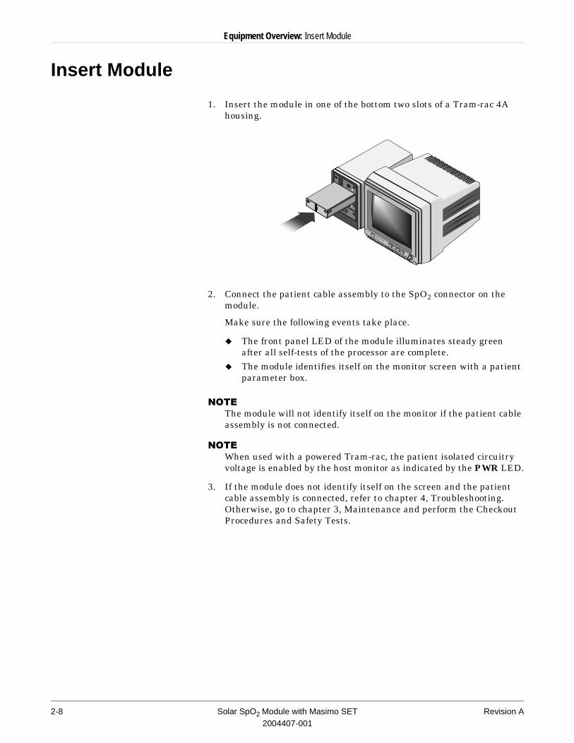
1. Insert the module in one of the bottom two slots of a Tram-rac 4A housing.
2. Connect the patient cable assembly to the SpO2 connector on the module.
Make sure the following events take place.
u The front panel LED of the module illuminates steady green after all self-tests of the processor are complete.
u The module identifies itself on the monitor screen with a patient parameter box.
127(�The module will not identify itself on the monitor if the patient cable assembly is not connected.
127(When used with a powered Tram-rac, the patient isolated circuitry voltage is enabled by the host monitor as indicated by the PWR LED.
3. If the module does not identify itself on the screen and the patient cable assembly is connected, refer to chapter 4, Troubleshooting. Otherwise, go to chapter 3, Maintenance and perform the Checkout Procedures and Safety Tests.
TRAMSCOPE 12
MARQUETTE
2-8 Solar SpO2 Module with Masimo SET Revision A2004407-001

3 Maintenance
Revision A Solar SpO2 Module with Masimo SET 3-12004407-001

For your notes
3-2 Solar SpO2 Module with Masimo SET Revision A2004407-001
Maintenance: Maintenance Schedule
Maintenance Schedule
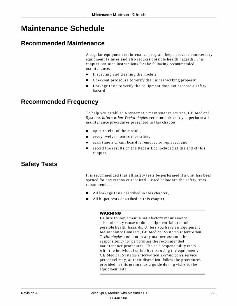
Recommended Maintenance
A regular equipment maintenance program helps prevent unnecessary equipment failures and also reduces possible health hazards. This chapter contains instructions for the following recommended maintenance:n Inspecting and cleaning the modulen Checkout procedure to verify the unit is working properlyn Leakage tests to verify the equipment does not propose a safety
hazard
Recommended Frequency
To help you establish a systematic maintenance routine, GE Medical Systems Information Technologies recommends that you perform all maintenance procedures presented in this chapter
n upon receipt of the module, n every twelve months thereafter, n each time a circuit board is removed or replaced, and n record the results on the Repair Log included at the end of this
chapter.
Safety Tests
It is recommended that all safety tests be performed if a unit has been opened for any reason or repaired. Listed below are the safety tests recommended.
n All leakage tests described in this chapter,n All hi-pot tests described in this chapter,
:$51,1*Failure to implement a satisfactory maintenance schedule may cause undue equipment failure and possible health hazards. Unless you have an Equipment Maintenance Contract, GE Medical Systems Information Technologies does not in any manner assume the responsibility for performing the recommended maintenance procedures. The sole responsibility rests with the individual or institution using the equipment. GE Medical Systems Information Technologies service personnel may, at their discretion, follow the procedures provided in this manual as a guide during visits to the equipment site.
Revision A Solar SpO2 Module with Masimo SET 3-32004407-001
Maintenance: Inspection and Cleaning
Inspection and Cleaning
Visual Inspection
Remove module before making an inspection or cleaning the module.n Check the case for cracks or other damage.n Regularly inspect cables for fraying or other damage.n Inspect all plugs, cables, and connectors for bent prongs or pins.n Verify that all cables and connectors are securely seated. Note that
replacement of components should be performed only by qualified service personnel.
Cleaning Precautions
Recommended cleaning supplies:n ammonia (diluted), orn Cidex solution, orn sodium hypochlorite bleach (diluted), orn mild soap (diluted), andn lint-free cloth, andn dust remover (compressed air)
To avoid damage to the equipment surfaces, do not use the following cleaning agents:n organic solvents, n ammonia based solutions, n acetone solution, n alcohol based cleaning agents, n Bentadine solution, n a wax containing a cleaning substance, or
n abrasive cleaning agents.
Exterior Cleaning
Clean the exterior surfaces with a clean, lint-free cloth and one of the cleaning solutions listed above.n Wring the excess water from the cloth. Do not drip any liquid into
open vents, plugs, or connectors.n Dry the surfaces with a clean cloth or paper towel.
3-4 Solar SpO2 Module with Masimo SET Revision A2004407-001
Maintenance: Checkout Procedure
Checkout Procedure
General
This procedure tests the functions of the module. The checkout procedures consist of the SpO2 tests.
These procedures are based on the assumption that the module under test is used with known good cables and known good test equipment. It also assumes that you are at least somewhat familiar with the operation of all devices required for the procedures. For more information concerning the operation of these components, consult the appropriate operator’s manuals.
Required Tools/Equipment
The following lists the test equipment, adapters, and cables necessary to complete the checkout procedures.
n Compatible Solar monitor and a Tram-rac 4A housing to power the module.
n Simulators and cables listed below provide waveforms and patient vital signs.
n Any patient cable or leadwire set that you would usually use on patients.
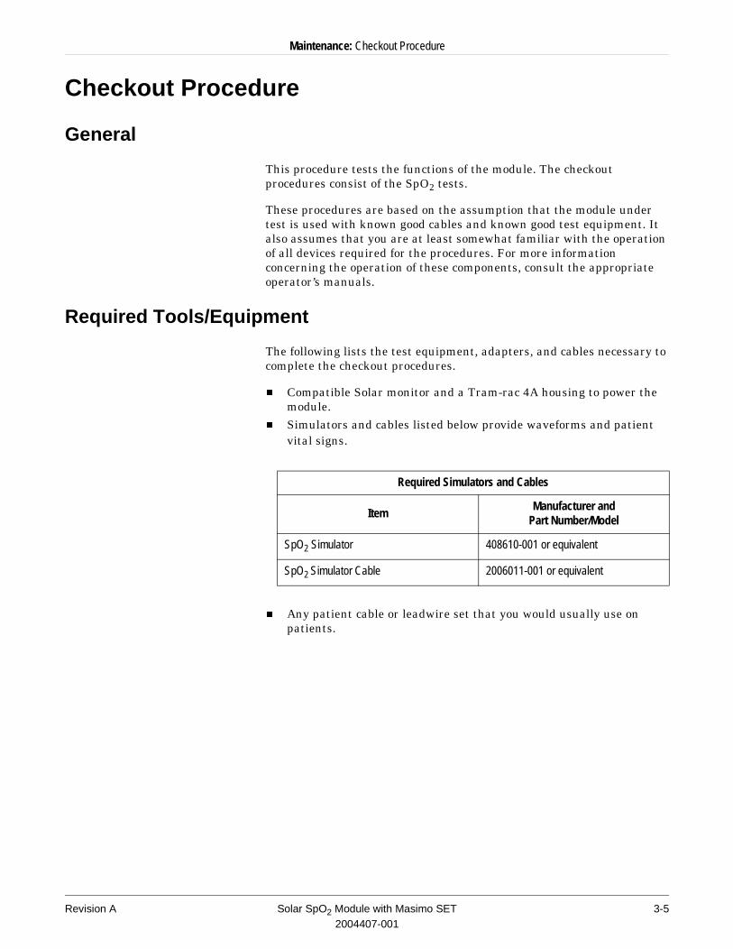
Required Simulators and Cables
ItemManufacturer and
Part Number/Model
SpO2 Simulator 408610-001 or equivalent
SpO2 Simulator Cable 2006011-001 or equivalent
Revision A Solar SpO2 Module with Masimo SET 3-52004407-001
Maintenance: Checkout Procedure
Preparation
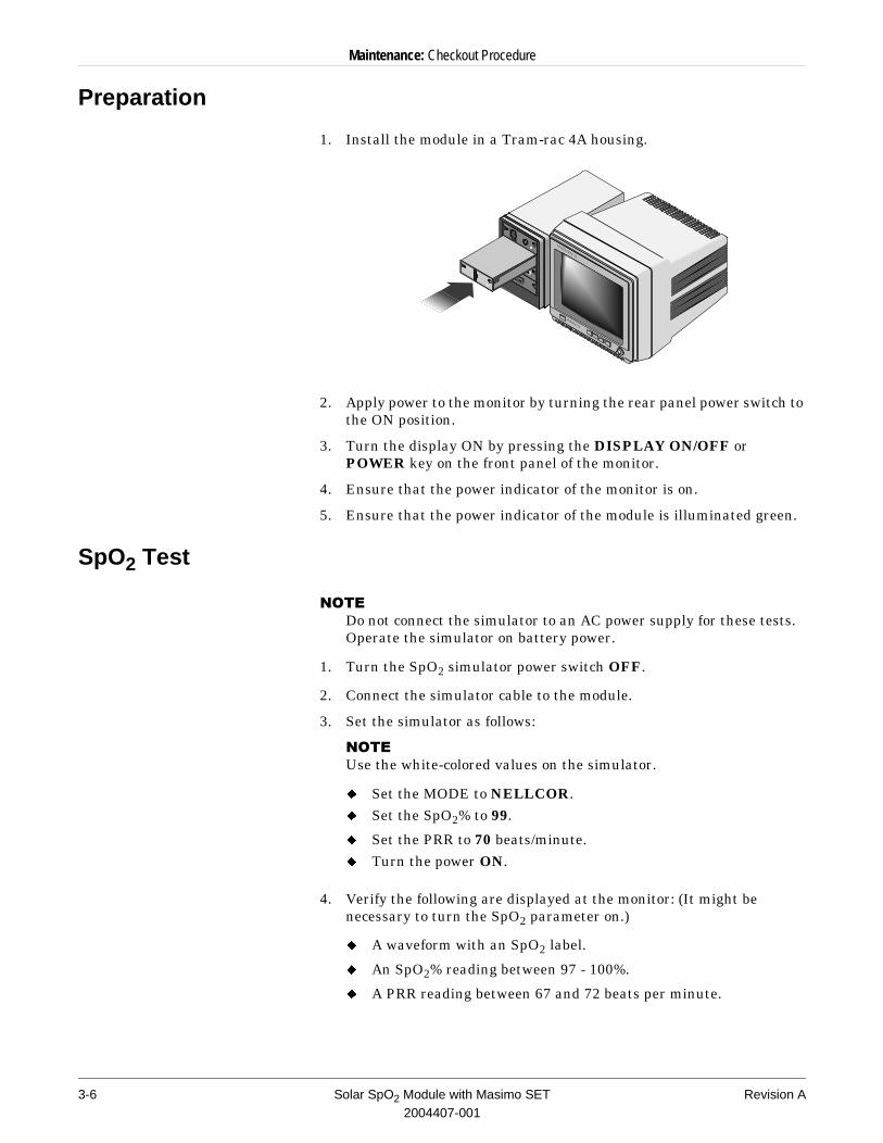
1. Install the module in a Tram-rac 4A housing.
2. Apply power to the monitor by turning the rear panel power switch to the ON position.
3. Turn the display ON by pressing the DISPLAY ON/OFF or POWER key on the front panel of the monitor.
4. Ensure that the power indicator of the monitor is on.
5. Ensure that the power indicator of the module is illuminated green.
SpO2 Test
127(�Do not connect the simulator to an AC power supply for these tests. Operate the simulator on battery power.
1. Turn the SpO2 simulator power switch OFF.
2. Connect the simulator cable to the module.
3. Set the simulator as follows:
127(�Use the white-colored values on the simulator.
u Set the MODE to NELLCOR.u Set the SpO2% to 99.
u Set the PRR to 70 beats/minute.u Turn the power ON.
4. Verify the following are displayed at the monitor: (It might be necessary to turn the SpO2 parameter on.)
u A waveform with an SpO2 label.
u An SpO2% reading between 97 - 100%.
u A PRR reading between 67 and 72 beats per minute.
TRAMSCOPE 12
MARQUETTE
3-6 Solar SpO2 Module with Masimo SET Revision A2004407-001
Maintenance: Checkout Procedure
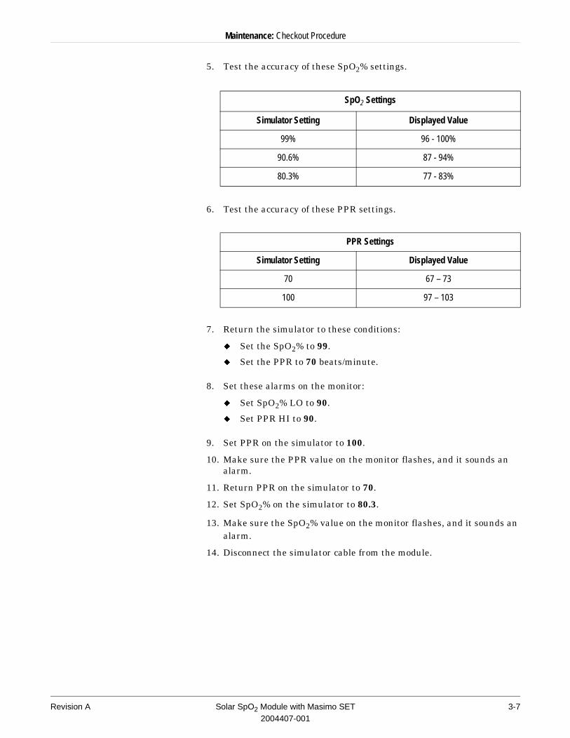
5. Test the accuracy of these SpO2% settings.
6. Test the accuracy of these PPR settings.
7. Return the simulator to these conditions:
u Set the SpO2% to 99.
u Set the PPR to 70 beats/minute.
8. Set these alarms on the monitor:
u Set SpO2% LO to 90.
u Set PPR HI to 90.
9. Set PPR on the simulator to 100.
10. Make sure the PPR value on the monitor flashes, and it sounds an alarm.
11. Return PPR on the simulator to 70.
12. Set SpO2% on the simulator to 80.3.
13. Make sure the SpO2% value on the monitor flashes, and it sounds an alarm.
14. Disconnect the simulator cable from the module.
SpO2 Settings
Simulator Setting Displayed Value
99% 96 - 100%
90.6% 87 - 94%
80.3% 77 - 83%
PPR Settings
Simulator Setting Displayed Value
70 67 – 73
100 97 – 103
Revision A Solar SpO2 Module with Masimo SET 3-72004407-001
Maintenance: Electrical Safety Tests
Electrical Safety Tests
Electrical safety tests provide a method of determining if potential electrical safety hazards to the patient or operator of the device exist.
Recommendations
GE Medical Systems Information Technologies recommends electrical safety tests be performed:
n upon receipt of the module, n every twelve months thereafter, andn each time the module is opened or repaired.
Record the date and results on the Repair Log included at the end of this chapter.
Required Tests
To help you establish a systematic maintenance routine, GE Medical Systems Information Technologies recommends that you perform all safety tests presented in this chapter.
These instructions are intended for every module in the system. The Tram-rac housing should remain connected to the host during the safety tests. Listed below are the safety tests.
n Hi-Pot TestsThese tests are mandatory when a module is opened or repaired.
n Leakage Current TestsThese tests are performed after the hi-pot tests.
If a module under test fails the leakage tests, call Tech Support for assistance. (Refer to “How to Reach Us” in front of this manual.)
Test Conditions
All electrical safety tests may be performed under normal ambient temperature, humidity, and pressure conditions with the module inserted in a Tram-rac 4A.
3-8 Solar SpO2 Module with Masimo SET Revision A2004407-001
Maintenance: Electrical Safety Tests
AC Hi-Pot Test
Hi-pot (high-potential) tests protect the patient from possible electrical safety hazards. They are recommended for any repaired patient-connected devices to ensure patient isolation after the repair.
Test Frequency
This test is required each time the module is opened or repaired.
:$51,1*Failure to perform hi-pot tests may cause undue equipment failure and possible health hazards. GE Medical Systems Information Technologies does not in any manner, unless an Equipment Maintenance Contract exists, assume the responsibility for performing this recommended health test. The sole responsibility rests with the individual or institution using the equipment.
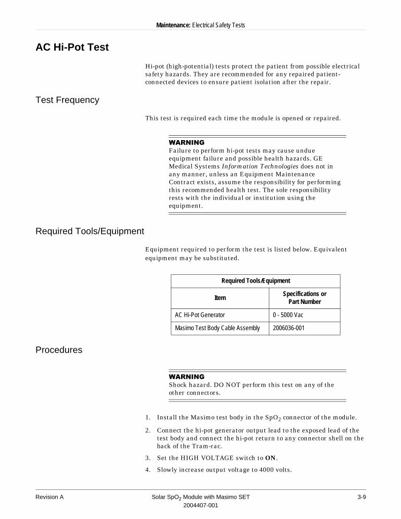
Required Tools/Equipment
Equipment required to perform the test is listed below. Equivalent equipment may be substituted.
Procedures
:$51,1*Shock hazard. DO NOT perform this test on any of the other connectors.
1. Install the Masimo test body in the SpO2 connector of the module.
2. Connect the hi-pot generator output lead to the exposed lead of the test body and connect the hi-pot return to any connector shell on the back of the Tram-rac.
3. Set the HIGH VOLTAGE switch to ON.
4. Slowly increase output voltage to 4000 volts.
Required Tools/Equipment
ItemSpecifications or
Part Number
AC Hi-Pot Generator 0 - 5000 Vac
Masimo Test Body Cable Assembly 2006036-001
Revision A Solar SpO2 Module with Masimo SET 3-92004407-001
Maintenance: Electrical Safety Tests
5. Wait for 60 seconds. There should be no indication of breakdown (warning lamp or buzzer).
6. Turn off the hi-pot tester and disconnect the leads.
7. If your module fails this test, contact GE Medical Systems Information Technologies Tech Support.
Current Leakage Tests
Preparation
The leakage current tests are safety tests to ensure that the equipment poses no electrical safety hazards. It is recommended after performing the hi-pot tests.
127(�These procedures test the integrity of this module only, not the entire system.
:$51,1*Failure to perform leakage tests may cause undue equipment failure and possible health hazards. GE Medical Systems Information Technologies does not in any manner, unless an Equipment Maintenance Contract exists, assume the responsibility for performing this recommended health test. The sole responsibility rests with the individual or institution using the equipment.
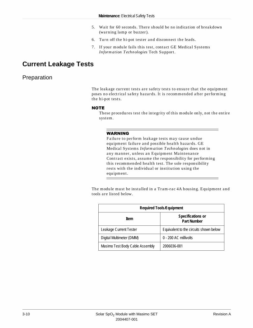
The module must be installed in a Tram-rac 4A housing. Equipment and tools are listed below.
Required Tools/Equipment
ItemSpecifications or
Part Number
Leakage Current Tester Equivalent to the circuits shown below
Digital Multimeter (DMM) 0 - 200 AC millivolts
Masimo Test Body Cable Assembly 2006036-001
3-10 Solar SpO2 Module with Masimo SET Revision A2004407-001
Maintenance: Electrical Safety Tests
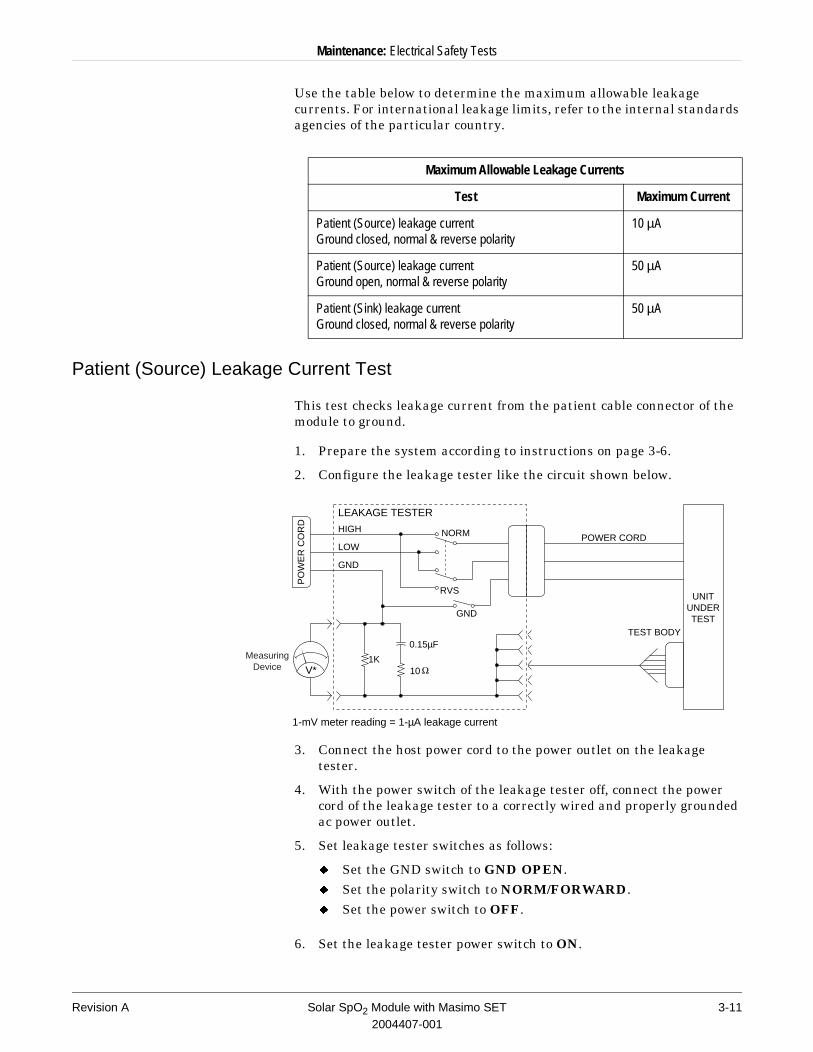
Use the table below to determine the maximum allowable leakage currents. For international leakage limits, refer to the internal standards agencies of the particular country.
Patient (Source) Leakage Current Test
This test checks leakage current from the patient cable connector of the module to ground.
1. Prepare the system according to instructions on page 3-6.
2. Configure the leakage tester like the circuit shown below.
3. Connect the host power cord to the power outlet on the leakage tester.
4. With the power switch of the leakage tester off, connect the power cord of the leakage tester to a correctly wired and properly grounded ac power outlet.
5. Set leakage tester switches as follows:
u Set the GND switch to GND OPEN.u Set the polarity switch to NORM/FORWARD.u Set the power switch to OFF.
6. Set the leakage tester power switch to ON.
Maximum Allowable Leakage Currents
Test Maximum Current
Patient (Source) leakage currentGround closed, normal & reverse polarity
10 µA
Patient (Source) leakage currentGround open, normal & reverse polarity
50 µA
Patient (Sink) leakage currentGround closed, normal & reverse polarity
50 µA
V*
POWER CORD
LEAKAGE TESTER
NORM
RVS
TEST BODY
HIGH
LOW
GND
1K
0.15µF
10
PO
WE
R C
OR
D
UNITUNDERTEST
1-mV meter reading = 1-µA leakage current
GND
MeasuringDevice
Revision A Solar SpO2 Module with Masimo SET 3-112004407-001
Maintenance: Electrical Safety Tests
7. Set the host rear panel power switch to ON.
8. Read the leakage current indicated on the measuring device.
9. Change the leakage tester polarity switch to the REVERSE position.
10. Read the leakage current indicated on the measuring device.
127(�If either reading is greater than 50 µA, the module fails this test. Contact GE Medical Systems Information Technologies Tech Support.
11. Change the GND switch to the CLOSED position.
12. Read the leakage current indicated on the measuring device.
13. Change the leakage tester polarity switch to the REVERSE position.
14. Read the leakage current indicated on the measuring device.
15. Set the power switch of the leakage tester to OFF.
If either reading is greater than 10 µA, the module fails this test. Contact GE Medical Systems Information Technologies Tech Support.
127(�The AAMI and IEC single fault condition (ground open) limit is 50 µA, whereas the normal condition (ground closed) limit is 10 µA.
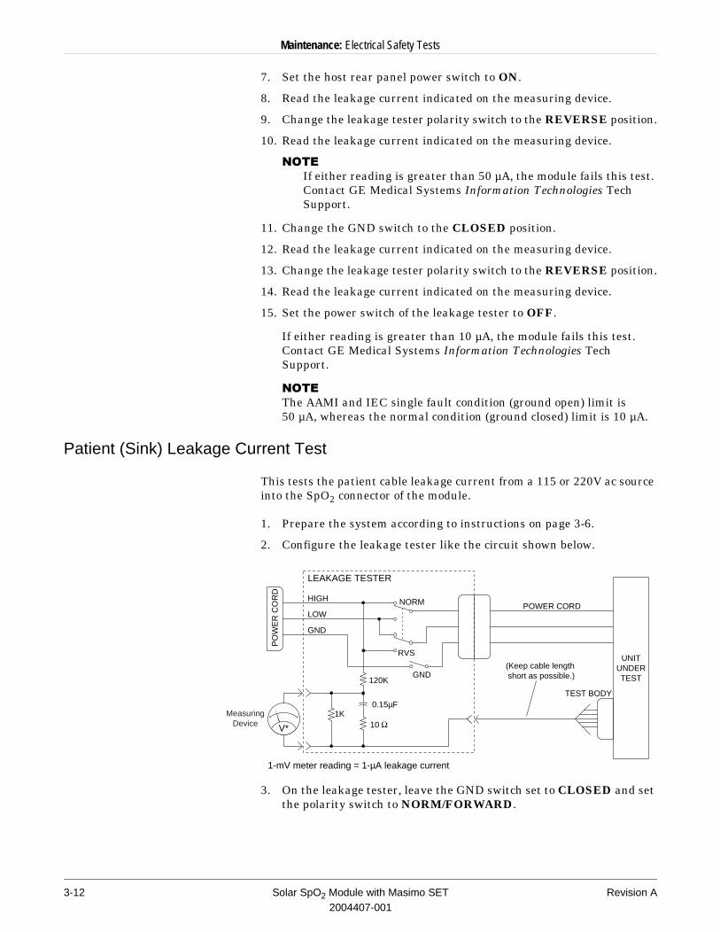
Patient (Sink) Leakage Current Test
This tests the patient cable leakage current from a 115 or 220V ac source into the SpO2 connector of the module.
1. Prepare the system according to instructions on page 3-6.
2. Configure the leakage tester like the circuit shown below.
3. On the leakage tester, leave the GND switch set to CLOSED and set the polarity switch to NORM/FORWARD.
V*
1K
POWER CORDNORM
RVS
TEST BODY
HIGH
LOW
GND
0.15µF
10
UNITUNDERTEST
PO
WE
R C
OR
D
1-mV meter reading = 1-µA leakage current
120K
(Keep cable length short as possible.)
LEAKAGE TESTER
GND
MeasuringDevice
3-12 Solar SpO2 Module with Masimo SET Revision A2004407-001
Maintenance: PM Form
:$51,1*Shock hazard. The following step causes high voltage at the test body. Do not touch the test body.
4. Set power switch on the leakage tester to ON.
5. Read leakage current indicated on measuring device.
6. Change the leakage tester polarity switch to the REVERSE position.
7. Read the leakage current indicated on the measuring device.
8. Set the power switch on the leakage tester to OFF.
If either reading is greater than 50 µA, the module fails this test. Contact GE Medical Systems Information Technologies Tech Support.
Completion
1. Disconnect all test equipment from the module.
2. Disconnect the host power cord from leakage tester.
3. Disconnect the tester from the power outlet.
PM Form
Due to continuing product innovation and because specifications in this manual are subject to change without notice, a PM form is not included with this manual. For the latest PM form regarding this product, contact a GE Medical Systems Information Technologies service representative.
On the following pages is a repair log to record the repair history of this product.
Revision A Solar SpO2 Module with Masimo SET 3-132004407-001
Maintenance: Repair Log
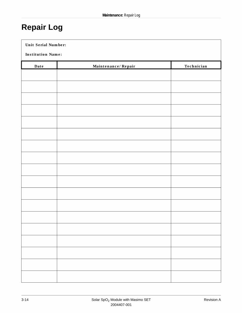
Repair Log
Unit Serial Number:
Institution Name:
Date Maintenance/Repair Technician
3-14 Solar SpO2 Module with Masimo SET Revision A2004407-001

Maintenance: Repair Log
Revision A Solar SpO2 Module with Masimo SET 3-152004407-001

Maintenance: Repair Log
3-16 Solar SpO2 Module with Masimo SET Revision A2004407-001
4 Troubleshooting
Revision A Solar SpO2 Module with Masimo SET 4-12004407-001

For your notes
4-2 Solar SpO2 Module with Masimo SET Revision A2004407-001
Troubleshooting: General Fault Isolation
General Fault Isolation
First Things to Ask
If the unit is not working properly ask these basic questions.
u Is the module seated correctly?u Is the monitor and Tram-rac housing power cord connected? u Is the monitor turned ON at the rear of the monitor?u Is the display LED illuminated? Are all the communication
cables firmly connected? u Were there any changes in the use, location, or environment of
the equipment that could cause the failure?u Has the unit been modified in any way, either in software or
hardware?
Is operator error the cause of the problem? Try to repeat the user’s scenario exactly and compare that to the proper operation of the equipment. Check the operator’s manual as necessary.
Visual Inspection
A thorough visual inspection of the equipment can save time. Small things—disconnected cables, foreign debris on circuit boards, missing hardware, loose components—can frequently cause symptoms and equipment failures that may appear to be unrelated and difficult to track.
Take the time to make all the recommended visual checks (refer to the visual inspection chart on the next page) before starting any detailed troubleshooting procedures.
Revision A Solar SpO2 Module with Masimo SET 4-32004407-001
Troubleshooting: General Fault Isolation
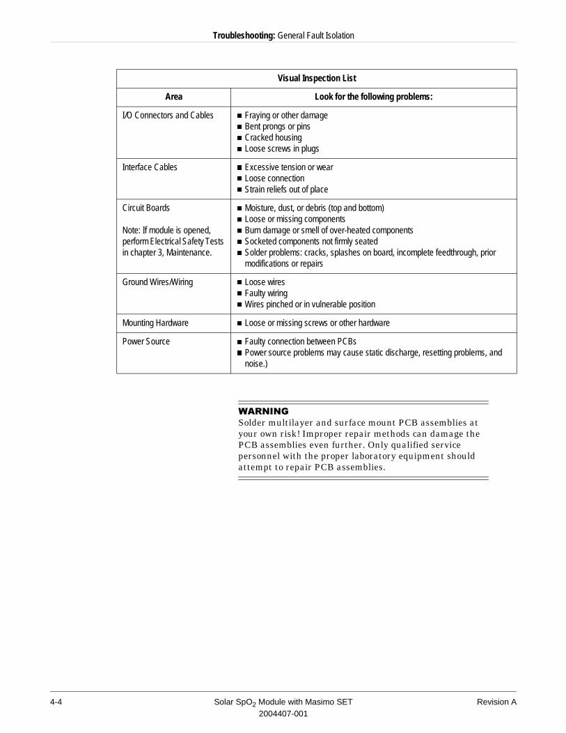
:$51,1*Solder multilayer and surface mount PCB assemblies at your own risk! Improper repair methods can damage the PCB assemblies even further. Only qualified service personnel with the proper laboratory equipment should attempt to repair PCB assemblies.
Visual Inspection List
Area Look for the following problems:
I/O Connectors and Cables n Fraying or other damagen Bent prongs or pinsn Cracked housingn Loose screws in plugs
Interface Cables n Excessive tension or wearn Loose connectionn Strain reliefs out of place
Circuit Boards
Note: If module is opened, perform Electrical Safety Tests in chapter 3, Maintenance.
n Moisture, dust, or debris (top and bottom)n Loose or missing componentsn Burn damage or smell of over-heated componentsn Socketed components not firmly seatedn Solder problems: cracks, splashes on board, incomplete feedthrough, prior
modifications or repairs
Ground Wires/Wiring n Loose wiresn Faulty wiringn Wires pinched or in vulnerable position
Mounting Hardware n Loose or missing screws or other hardware
Power Source n Faulty connection between PCBsn Power source problems may cause static discharge, resetting problems, and
noise.)
4-4 Solar SpO2 Module with Masimo SET Revision A2004407-001
Troubleshooting: Troubleshooting Procedure
Troubleshooting Procedure
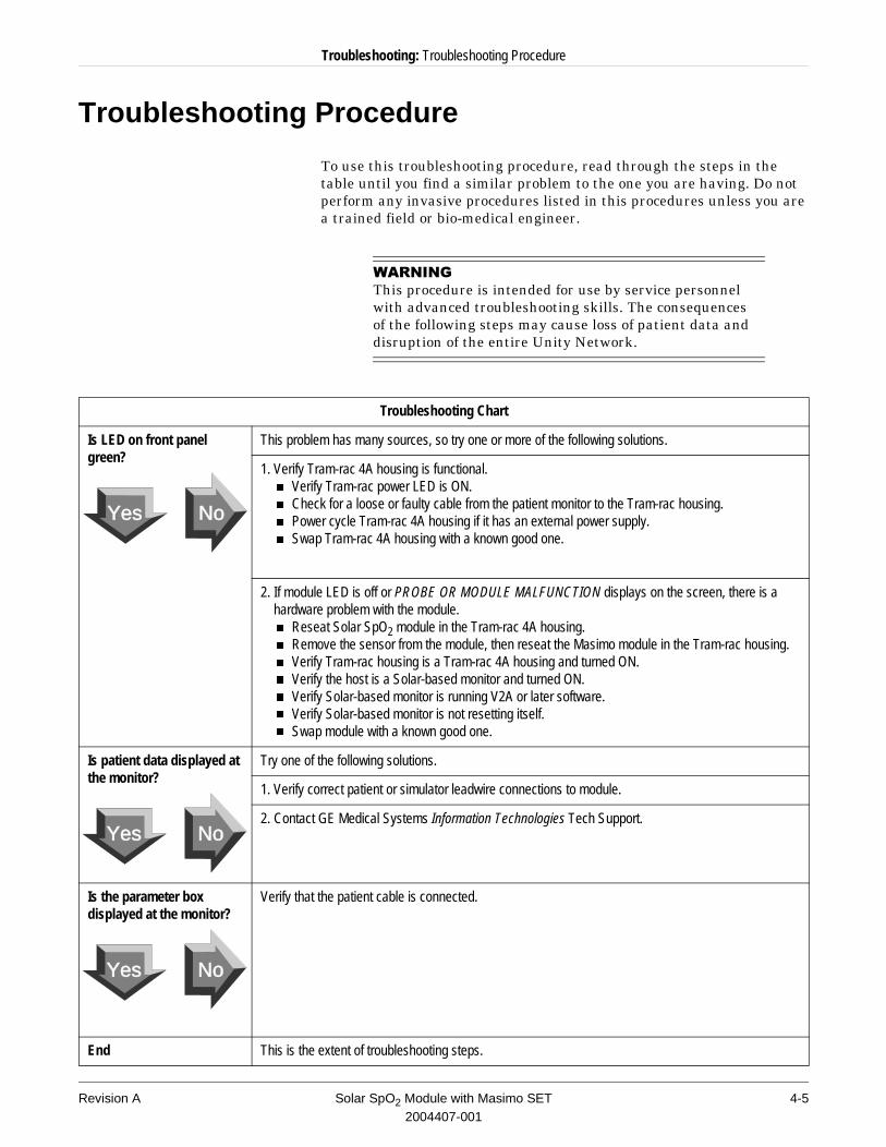
To use this troubleshooting procedure, read through the steps in the table until you find a similar problem to the one you are having. Do not perform any invasive procedures listed in this procedures unless you are a trained field or bio-medical engineer.
:$51,1*This procedure is intended for use by service personnel with advanced troubleshooting skills. The consequences of the following steps may cause loss of patient data and disruption of the entire Unity Network.
Troubleshooting Chart
Is LED on front panel green?
This problem has many sources, so try one or more of the following solutions.
1. Verify Tram-rac 4A housing is functional.n Verify Tram-rac power LED is ON.n Check for a loose or faulty cable from the patient monitor to the Tram-rac housing.n Power cycle Tram-rac 4A housing if it has an external power supply.n Swap Tram-rac 4A housing with a known good one.
2. If module LED is off or PROBE OR MODULE MALFUNCTION displays on the screen, there is a hardware problem with the module.n Reseat Solar SpO2 module in the Tram-rac 4A housing.n Remove the sensor from the module, then reseat the Masimo module in the Tram-rac housing.n Verify Tram-rac housing is a Tram-rac 4A housing and turned ON.n Verify the host is a Solar-based monitor and turned ON.n Verify Solar-based monitor is running V2A or later software.n Verify Solar-based monitor is not resetting itself.n Swap module with a known good one.
Is patient data displayed at the monitor?
Try one of the following solutions.
1. Verify correct patient or simulator leadwire connections to module.
2. Contact GE Medical Systems Information Technologies Tech Support.
Is the parameter box displayed at the monitor?
Verify that the patient cable is connected.
End This is the extent of troubleshooting steps.
Yes No
Yes No
Yes No
Revision A Solar SpO2 Module with Masimo SET 4-52004407-001
Troubleshooting: Troubleshooting Procedure
System OK LED
The system LED, DS1, is red and is located inside the module. This LED indicates whether the software is operating normally. The status of the LED toggles each time the module completes transmitting a packet to the host patient monitor.
MS-3 Communications OK LED
The MS-3 communications LED, DS2, is yellow and is located inside the module. This LED indicates whether communications between the Masimo MS-3 analyzer and the system processor are operating normally. The LED toggles if a complete data packet is received from the Masimo MS-3 analyzer pcb.
Isolated Power Supply OK LED
The isolated power supply LED, DS3, is green and is located on the front panel of the module. This LED indicates whether the isolated power supply is operating normally. The LED is illuminated if power is applied to the Masimo MS-3 analyzer pcb.
4-6 Solar SpO2 Module with Masimo SET Revision A2004407-001
Troubleshooting: Theory of Operation
Theory of Operation
Hardware Functions
The Masimo SET SpO2 Module, hereafter referred to as the Masimo module, provides all the hardware necessary to communicate with a host patient monitor and continuously monitor the functional oxygen saturation of arterial hemoglobin (SpO2) and pulse rate. The hardware features include the following items:
n Bedside communications using the Synchronous Serial Shift Register Interface protocol.
n Masimo MS-3 analyzer communications and controln Input power conditioning and soft-start current limitingn Code download - from host or BDMn 4000 Volt patient isolation
Software Functions
The Masimo module PCB performs the communications with the Masimo MS-3 Analyzer PCB and host bedside communications. The device performs the following functions under software control:
n Bedside communications and error detectionn Masimo MS-3 Analyzer communications and controln SpO2 value calculation
n Respiration rate calculationn Error detection and alarm indicationn Initialization and self test
System Processor
The system processor uses external memory for operation. There is a 512K x 8 static RAM for temporary data storage.
127(�The static RAM is not battery backed-up, therefore this device is not a transportable patient monitor such as the TRAM module.
The static RAM is also used as temporary storage of Masimo MS-3 program code during program download of the MS-3 software. The program code is stored in a 128K x 8 sectored FLASH EPROM. This device can be erased on an individual sector basis. The first sector of FLASH is used for storing the BOOT code. This insures that even if a download of code fails the module still attempts another download of code. The other seven sectors of FLASH store the MAIN code. The MAIN code operates during normal operation of the module. This code can be updated using the host patient monitor.
Revision A Solar SpO2 Module with Masimo SET 4-72004407-001
Troubleshooting: Theory of Operation
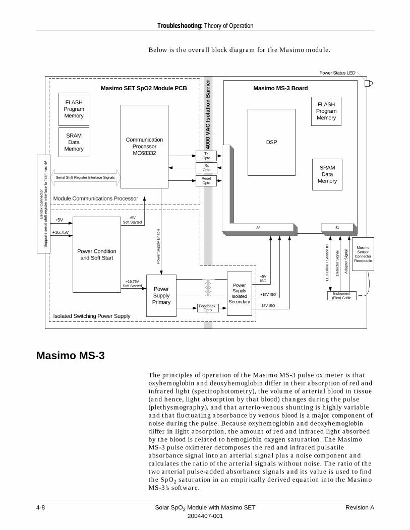
Below is the overall block diagram for the Masimo module.
Masimo MS-3
The principles of operation of the Masimo MS-3 pulse oximeter is that oxyhemoglobin and deoxyhemoglobin differ in their absorption of red and infrared light (spectrophotometry), the volume of arterial blood in tissue (and hence, light absorption by that blood) changes during the pulse (plethysmography), and that arterio-venous shunting is highly variable and that fluctuating absorbance by venous blood is a major component of noise during the pulse. Because oxyhemoglobin and deoxyhemoglobin differ in light absorption, the amount of red and infrared light absorbed by the blood is related to hemoglobin oxygen saturation. The Masimo MS-3 pulse oximeter decomposes the red and infrared pulsatile absorbance signal into an arterial signal plus a noise component and calculates the ratio of the arterial signals without noise. The ratio of the two arterial pulse-added absorbance signals and its value is used to find the SpO2 saturation in an empirically derived equation into the Masimo MS-3’s software.
MasimoSensor
ConnectorReceptacle
Instrument(Flex) Cable
Masimo SET SpO2 Module PCB
Isolated Switching Power Supply
Masimo MS-3 Board
Power Status LED
PowerSupplyIsolated
Secondary
PowerSupplyPrimary
Power Conditionand Soft Start
CommunicationProcessorMC68332
Feedback Opto
+5V
+16.75VSoft Started
+16.75V
+5VSoft Started
+5VISO
+15V ISO
-15V ISO
LED
Driv
e / S
enso
r ID
Det
ecto
r S
igna
l
Ada
pter
Sig
nal
DSP
FLASHProgramMemory
FLASHProgramMemory
SRAMData
Memory
SRAMData
MemorySerial Shift Register Interface Signals
J3 J1
RxOpto
TxOpto
Ben
dix
Con
nect
orS
uppo
rts
seria
l shi
ft re
gist
er in
terf
ace
to T
ram
-rac
4A
4000
VA
C Is
olat
ion
Bar
rier
ResetOpto
Pow
er S
uppl
y E
nabl
e
Module Communications Processor
4-8 Solar SpO2 Module with Masimo SET Revision A2004407-001
Troubleshooting: Theory of Operation
Host Patient Monitor Communications
The Masimo module communicates with the host patient monitor using the synchronous Serial Shift Register Interface Signals. The communication processor performs this function, operating in slave mode it receives clock and enable signals from the host patient monitor.
All integrated circuits with signals connected to the backplane are powered directly from the backplane +5 volts not the soft-started power supplies. This is so the signals won’t load down the synchronous Serial Shift Register Interface Signals upon insertion of the module.
Power Condition and Soft Start
The Masimo module receives power from the host Tram-rac. The module is designed for insertion into a live Tram-rac. All the power supply pins incorporate soft-start circuitry to limit inrush currents. This module uses the +5V and +16.5V power supplies from the host patient monitor.
Isolated Power Supply
The Masimo module uses an isolated power supply to power the Masimo MS-3 board. The power supply is designed to provide 4000 volts of patient isolation from the host patient monitor. The isolated power supply generates +5V, +15V, and -15V and is controlled by the system processor.
The system processor monitors signal PS_FAULT which indicates a fault condition with the power supply. If this signal is active (logic high) for more than 200ms, the system processor shuts down the isolated power supply. The system processor does not monitor this line for the first 100ms after the power supply is enabled allowing the isolated power supply time to stabilize.
Patient Connector Flex Circuit
The flex circuit assembly provides the connection from the Masimo MS-3 analyzer to the patient receptacle on the front panel of the module. The Masimo Flex PCB includes a ferrite core to reduce electromagnetic emissions/susceptibility and a shield around the front panel connector to reduce susceptibility to external interference.
Revision A Solar SpO2 Module with Masimo SET 4-92004407-001
Troubleshooting: External Connectors
External Connectors
Pin-by-pin descriptions and the signal names for each connector on the front panel of the module are described in this section.
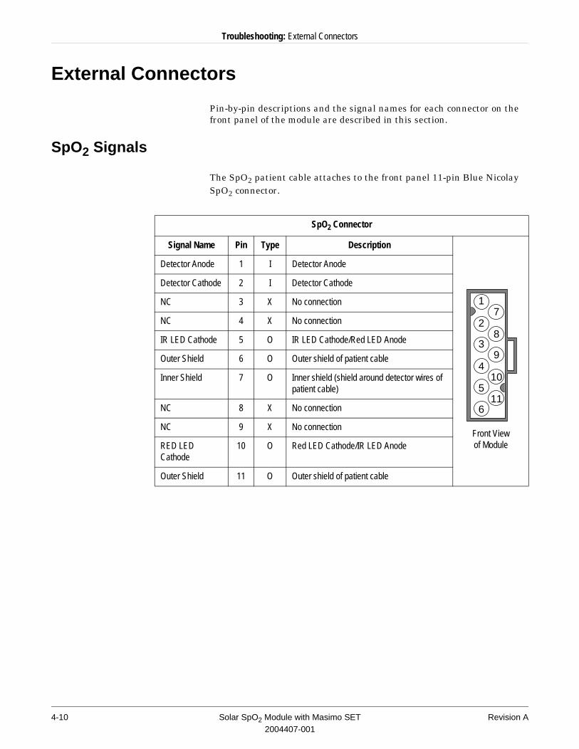
SpO2 Signals
The SpO2 patient cable attaches to the front panel 11-pin Blue Nicolay SpO2 connector.
SpO2 Connector
Signal Name Pin Type Description
Front View of Module
Detector Anode 1 I Detector Anode
Detector Cathode 2 I Detector Cathode
NC 3 X No connection
NC 4 X No connection
IR LED Cathode 5 O IR LED Cathode/Red LED Anode
Outer Shield 6 O Outer shield of patient cable
Inner Shield 7 O Inner shield (shield around detector wires of patient cable)
NC 8 X No connection
NC 9 X No connection
RED LED Cathode
10 O Red LED Cathode/IR LED Anode
Outer Shield 11 O Outer shield of patient cable
1
2
3
4
5
6
7
8
9
10
11
4-10 Solar SpO2 Module with Masimo SET Revision A2004407-001
Troubleshooting: External Connectors
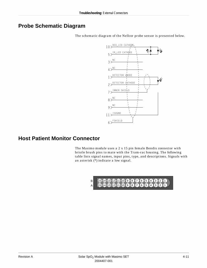
Probe Schematic Diagram
The schematic diagram of the Nellcor probe sensor is presented below.
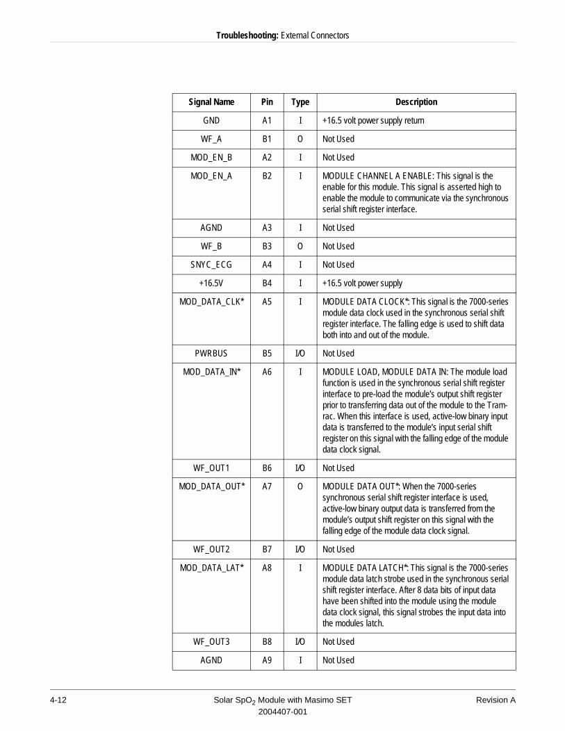
Host Patient Monitor Connector
The Masimo module uses a 2 x 15 pin female Bendix connector with bristle brush pins to mate with the Tram-rac housing. The following table lists signal names, input pins, type, and descriptions. Signals with an asterisk (*) indicate a low signal.
3
10
5
8
1
6
4
7
2
9
11
RED_LED CATHODE
IR_LED CATHODE
NC
NC
DETECTOR ANODE
DETECTOR CATHODE
INNER SHIELD
NC
NC
ISOGND
FSHIELD
15 14 13 12 11 10 9 8 7 6 5 4 3 2 1
15 14 13 12 11 10 9 8 7 6 5 4 3 2 1
B
A
Revision A Solar SpO2 Module with Masimo SET 4-112004407-001
Troubleshooting: External Connectors
Signal Name Pin Type Description
GND A1 I +16.5 volt power supply return
WF_A B1 O Not Used
MOD_EN_B A2 I Not Used
MOD_EN_A B2 I MODULE CHANNEL A ENABLE: This signal is the enable for this module. This signal is asserted high to enable the module to communicate via the synchronous serial shift register interface.
AGND A3 I Not Used
WF_B B3 O Not Used
SNYC_ECG A4 I Not Used
+16.5V B4 I +16.5 volt power supply
MOD_DATA_CLK* A5 I MODULE DATA CLOCK*: This signal is the 7000-series module data clock used in the synchronous serial shift register interface. The falling edge is used to shift data both into and out of the module.
PWRBUS B5 I/O Not Used
MOD_DATA_IN* A6 I MODULE LOAD, MODULE DATA IN: The module load function is used in the synchronous serial shift register interface to pre-load the module’s output shift register prior to transferring data out of the module to the Tram-rac. When this interface is used, active-low binary input data is transferred to the module’s input serial shift register on this signal with the falling edge of the module data clock signal.
WF_OUT1 B6 I/O Not Used
MOD_DATA_OUT* A7 O MODULE DATA OUT*: When the 7000-series synchronous serial shift register interface is used, active-low binary output data is transferred from the module’s output shift register on this signal with the falling edge of the module data clock signal.
WF_OUT2 B7 I/O Not Used
MOD_DATA_LAT* A8 I MODULE DATA LATCH*: This signal is the 7000-series module data latch strobe used in the synchronous serial shift register interface. After 8 data bits of input data have been shifted into the module using the module data clock signal, this signal strobes the input data into the modules latch.
WF_OUT3 B8 I/O Not Used
AGND A9 I Not Used
4-12 Solar SpO2 Module with Masimo SET Revision A2004407-001
Troubleshooting: External Connectors
Software Updates
Two types of downloading procedures are available for the Masimo module. Software may be downloaded from a programmed software diskette using a patient monitor by either of the following two ways:
n from a laptop personal computer or terminal, orn across the Unity Network from a central station.
These procedures are explained in detail in the software upgrade kit. Contact your GE Medical Systems Information Technologies service representative for information.
123KHZ B9 I Not Used
CALIBRATE* A10 I Not Used
WF_OUT5 B10 O Not Used
GND A11, B11
I GROUND: These pins are the logic reference and the +5V power supply return lines.
TN_ENA* A12 O TRAMNET ENABLE*: When high this signal identifies the device’s communication protocol as the synchronous serial shift register interface. When low this signal identifies the device’s communication protocol as Tramnet.
+5 B12 I +5V DIGITAL POWER: +5V power supply to the module for the device digital circuitry.
+15V A13, B13
I Not Used
-15V A14, B14
I Not Used
AGND A15, B15
I Not Used
Signal Name Pin Type Description
Revision A Solar SpO2 Module with Masimo SET 4-132004407-001

Troubleshooting: External Connectors
For your notes
4-14 Solar SpO2 Module with Masimo SET Revision A2004407-001

5 Parts Lists and Drawings
Revision A Solar SpO2 Module with Masimo SET 5-12004407-001

For your notes
5-2 Solar SpO2 Module with Masimo SET Revision A2004407-001
Parts Lists and Drawings: Ordering Parts
Ordering Parts
General
The parts lists and assembly drawings in this chapter supply enough detail for you to order parts for the assemblies considered field serviceable. If you require additional information or troubleshooting assistance, contact Tech Support.
To order parts, contact Service Parts at the address or telephone number listed on the “How to Reach Us...,” page found at the front of this manual.
Field Replaceable Units
The tables below list the most commonly replaced assemblies ordered in the service spare circuit board kits.
The following is a list of all accessories available for the Masimo SET SpO2 Module.
Field Replaceable Units
Item Part Number
Masimo SET SpO2 Module PCB 2001857-001
Masimo SET SpO2 Module Flex PCB 2001861-001
Masimo SET SpO2 MS-3 PCB 2002271-001
Accessories
Description Part Number
Cable Assy Patient Adapter Masimo SpO2 12 FT 2002592-001
Cable Assy Patient Adapter Masimo SpO2 8 FT 2002592-002
Kit Samples Masimo Adult/Pediatric Sensors 2002797-001
Masimo LNOP Adt Adult Sensor N/A
Masimo LNOP Pdt Pediatric Sensor N/A
Kit Samples Masimo Neonatal Sensors 2002798-001
Masimo LNOP Neo Neonatal Sensor N/A
Masimo LNOP NeoPt Neonatal Sensor N/A
Masimo LNOP DC1P Reusable Finger Sensor Pediatric 2002799-001
Masimo LNOP DC1 Reusable Finger Sensor Adult 2002800-001
Revision A Solar SpO2 Module with Masimo SET 5-32004407-001
Parts Lists and Drawings: Disassembly Procedures
Disassembly Procedures
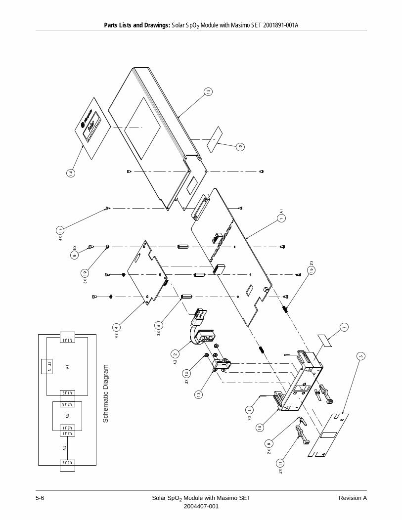
Refer to the exploded view that follows these procedures for part location.
Assembly Housing
1. Remove 2 screws from the module top and 2 screws from the module bottom.
2. Slide the housing away from the bezel.
Masimo SET SpO2 MS-3 PCB
1. Remove the assembly housing according to the steps above.
2. Remove 3 screws from the MS-3 PCB and pull the PCB up and away from the spacers.
3. Disconnect the Masimo module flex PCB from the MS-3 PCB and remove the MS-3 PCB.
Masimo SET SpO2 Module Flex PCB
1. Remove the assembly housing and the Masimo module MS-3 PCB according to the steps above.
2. Disconnect ends of the flex assembly and remove.
Masimo SET SpO2 Module PCB
When the assembly housing, the MS-3 PCB, and the flex PCB are removed according to the steps above, the Masimo module PCB is loose and can be removed.
Reassembly
Reverse the above steps to reassemble the Masimo module.
Testing
Perform the Electrical Safety Tests described in chapter 3, Maintenance.
5-4 Solar SpO2 Module with Masimo SET Revision A2004407-001
Parts Lists and Drawings: Solar SpO2 Module with Masimo SET 2001891-001A
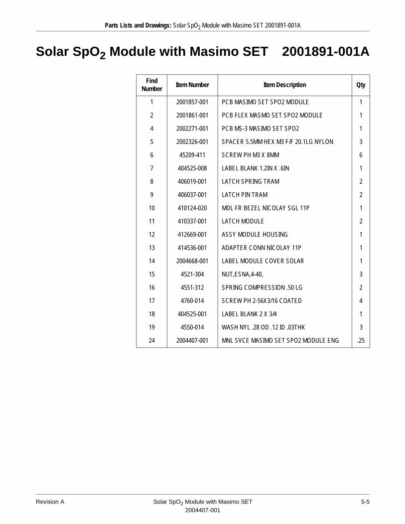
Solar SpO2 Module with Masimo SET 2001891-001A
Find Number
Item Number Item Description Qty
1 2001857-001 PCB MASIMO SET SPO2 MODULE 1
2 2001861-001 PCB FLEX MASMO SET SPO2 MODULE 1
4 2002271-001 PCB MS-3 MASIMO SET SPO2 1
5 2002326-001 SPACER 5.5MM HEX M3 F/F 20.1LG NYLON 3
6 45209-411 SCREW PH M3 X 8MM 6
7 404525-008 LABEL BLANK 1.2IN X .6IN 1
8 406019-001 LATCH SPRING TRAM 2
9 406037-001 LATCH PIN TRAM 2
10 410124-020 MDL FR BEZEL NICOLAY SGL 11P 1
11 410337-001 LATCH MODULE 2
12 412669-001 ASSY MODULE HOUSING 1
13 414536-001 ADAPTER CONN NICOLAY 11P 1
14 2004668-001 LABEL MODULE COVER SOLAR 1
15 4521-304 NUT,ESNA,4-40, 3
16 4551-312 SPRING COMPRESSION .50 LG 2
17 4760-014 SCREW PH 2-56X3/16 COATED 4
18 404525-001 LABEL BLANK 2 X 3/4 1
19 4550-014 WASH NYL .28 OD .12 ID .03THK 3
24 2004407-001 MNL SVCE MASIMO SET SPO2 MODULE ENG .25
Revision A Solar SpO2 Module with Masimo SET 5-52004407-001
Parts Lists and Drawings: Solar SpO2 Module with Masimo SET 2001891-001A
Sch
emat
ic D
iagr
am
5-6 Solar SpO2 Module with Masimo SET Revision A2004407-001