Solar pumping inverter user manual
15
Transcript of Solar pumping inverter user manual

Solar pumping inverter user manual
1、Electrical cable Connection
Please follow the diagram below for wiring. And pay attention to the following issues:
The power output of the PV panel is connected to the “+” and “-” terminals. Please note that the
polarity is not reversed.
Make sure that the inverter input AC voltage level is consistent with AC grid voltage before connecting
with Input “R”, “S” and “T” terminals
If Grid is single-phase power supply, you can connect to R T or any two terminals of “R”, “S” and “T”。
DI1 defaults to the running terminal input.
AI2 defaults to the water tank level detection signal input, which is used to control the inverter
sleep and auto start.
Relay 1 output defaults to the fault signal output.
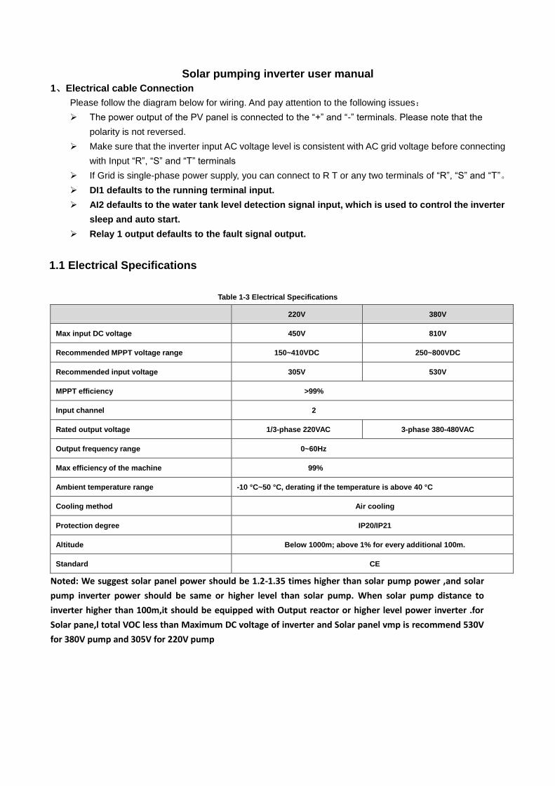
1.1 Electrical Specifications
Table 1-3 Electrical Specifications
220V 380V
Max input DC voltage 450V 810V
Recommended MPPT voltage range 150~410VDC 250~800VDC
Recommended input voltage 305V 530V
MPPT efficiency >99%
Input channel 2
Rated output voltage 1/3-phase 220VAC 3-phase 380-480VAC
Output frequency range 0~60Hz
Max efficiency of the machine 99%
Ambient temperature range -10 °C~50 °C, derating if the temperature is above 40 °C
Cooling method Air cooling
Protection degree IP20/IP21
Altitude Below 1000m; above 1% for every additional 100m.
Standard CE
Noted: We suggest solar panel power should be 1.2-1.35 times higher than solar pump power ,and solar
pump inverter power should be same or higher level than solar pump. When solar pump distance to
inverter higher than 100m,it should be equipped with Output reactor or higher level power inverter .for
Solar pane,l total VOC less than Maximum DC voltage of inverter and Solar panel vmp is recommend 530V
for 380V pump and 305V for 220V pump

M
U
V
W
R
S
T
3 phase power
input
DI1
DI2
DI3
DI4
COM
AI1
AI2
GND
485+
485-RS485 port
AO2
GND
AO1、AO2 output:
0~10V/0~20mA
DO1
COMT1A
T1C
T1B
+10V
PLC
+24V+24V
-+ PB
HDI
HDO
COM
AO1
Water tank level
feedback Relay 1 output,
Default is fault signal
output
485ON
OFF
AI1V
AI2V
I I I I
AO1V
AO2V
ON ON
OFF OFF
Grounding
Connector slip
GND
Main circuit
Control circuit
Q2Solar panels
Q1
Start/stop
terminal
Wire Diagram of solar pump inverter
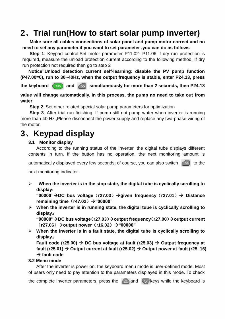
2、Trial run(How to start solar pump inverter) Make sure all cables connections of solar panel and pump motor correct and no
need to set any parameter,if you want to set parameter ,you can do as follows
Step 1: Keypad control:Set motor parameter P11.02- P11.06 If dry run protection is
required, measure the unload protection current according to the following method. If dry
run protection not required then go to step 2
Notice”Unload detection current self-learning: disable the PV pump function
(P47.00=0), run to 30~40Hz, when the output frequency is stable, enter P24.13, press
the keyboard and simultaneously for more than 2 seconds, then P24.13
value will change automatically. In this process, the pump no need to take out from
water
Step 2: Set other related special solar pump parameters for optimization
Step 3: After trial run finishing, If pump still not pump water when inverter is running
more than 40 Hz.,Please disconnect the power supply and replace any two-phase wiring of
the motor.
3、Keypad display 3.1 Monitor display
According to the running status of the inverter, the digital tube displays different
contents in turn. If the button has no operation, the next monitoring amount is
automatically displayed every few seconds; of course, you can also switch to the
next monitoring indicator
When the inverter is in the stop state, the digital tube is cyclically scrolling to
display:
“00000”DC bus voltage(r27.03)given frequency(r27.01) Distance
remaining time(r47.02)“00000”
When the inverter is in running state, the digital tube is cyclically scrolling to
display.:
“00000”DC bus voltage(r27.03)output frequency(r27.00)output current
(r27.06)output power(r16.02)“00000”
When the inverter is in a fault state, the digital tube is cyclically scrolling to
display.:
Fault code (r25.00) DC bus voltage at fault (r25.03) Output frequency at
fault (r25.01) Output current at fault (r25.02) Output power at fault (r25. 16)
fault code
3.2 Menu mode
After the inverter is power on, the keyboard menu mode is user-defined mode. Most
of users only need to pay attention to the parameters displayed in this mode. To check
the complete inverter parameters, press the and keys while the keyboard is

displayed . When the keyboard is displayed , press the key
to enter the basic menu mode.
3.3 Error code:For other alarm codes, please refer to Chapter 5 of the manual.
alarm code meaning
Er.CCC Light weak fault, please refer to
function code P47.05~P47.07
4、Parameter list Symbol Description:
“☆” means that the set value of this parameter can be changed no matter the inverter is in
the stop state or in running state.
“★” indicates that the set value of this parameter cannot be changed while the inverter is
running.
“●” indicates that the value of this parameter is the actual detected record value and cannot
be changed.
47 Group solar pumping special group
Function
code
Name Description Default Propert
y
47 Group solar pumping special group
P47.00 Solar pump function
enable
0: invalid
The parameters behind the 47 group cannot
be changed!
1: Enable, to enable the special function of
the PV pump inverter
1 ★
P47.01
Solar pump control
mode
Units digit’s: Startup mode
0: Manual start, the start mode is
determined by P00.06;
1: automatic start,
Ten digit’s: MPPT function
0: MPPT is disabled; CVT control is used
(voltage is given as P47.04).
1: Enable MPPT.
11 ★
r47.02
Remaining time for
starting
The remaining time of the starting is
displayed In auto start mode,
Unit: second
-- ●
P47.03 Automatic start timing
In auto start mode, set the time from power
on to start.
600 ★
P47.04 MPPT starting voltage Set the starting voltage of the MPPT 305V(530V ★
Function
code
Name Description Default Propert
y
algorithm.
When the MPPT function is disabled, this
value is the reference voltage.
When the MPPT function is enabled, the
inverter searches up and down from this
value. for the maximum power point up or
down
220V level DC 305V/ 380V Default DC 530V
P47.05 Light detection
threshold
If the output frequency is lower than this value
and exceeds P47.06, it will be reported to
Er.CCC.
0Hz ☆
P47.06 Light detection time See P47.05 for explanation. 60s ☆
P47.07 Light weak wake up
time
After the Er.CCC fault is reported, if the time
when Vdc is higher than the undervoltage
point is greater than the set value, the fault
state is exited and the operation continues.
120s ☆
P47.08 MPPT tracking step
length
The amount of change in the bus voltage
during an MPPT cycle. The larger the value,
the faster the maximum power point is found,
but the lower the accuracy of the maximum
power point.
02 ☆
P47.09 Regulator proportional
gain 0.01~1.00 0.05 ☆
P47.10 Regulator integral gain 0.001~0.100 0.05 ☆
r47.11 Pumping flow
0.1 m3
It shows the amount of water pumping today,
it will be cleared after power down.
0.0 m³ ●
r47.12 Cumulative pumping
flow volume
1 m3, 32 digits
It shows the pumping flow volume
accumulated by the pump. The power can be
saved automatically after power-on, and
continue to accumulate on the original basis
after re-powering. It Can be cleared to zero by
P47.14.
0 m³ ●
P47.14 Cumulative pumping
reset
Set 1 to clear zero for r47.12. This function
code automatically changes to 0 after the
reset is completed.
0 ☆
r47.15 Current traffic 0.1 m3/h 0.0 m³/h ●
P47.16 Pump rated flow 0.1 m3/h 0.0 m³/h ☆
P47.17 Pump water frequency Set the output frequency of the inverter when
the pump can pump water. 20.00Hz ☆

Function
code
Name Description Default Propert
y
24 group Pump dry run protection/unload detection parameter
P24.12 Dry run/Unload
protection option
0: No offload detection is performed;
1: Enable offload detection
1 ☆
P24.13 Dry run/Unload
detection level
0.0 to 100.0%
The percentage of motor rated current. 0.0% ☆
P24.14 Dry run Unload
detection time 0.000s~60.000s 30.000s ☆
41 Group Pump sleep and wake-up parameters:
P41.00 Sleep/wake source
selection
Unit digit’s: Sleep source selection
0: no sleep function
2: AI1 sleep
3: AI2 sleep
Tens digit’s: wake up source selection
1: AI1 wakes up
2: AI2 wakes up
Note: If the AI2 is connected to the level
detection signal, set this value to "23". If there
is no sleep source (one digit is 0), the
wake-up function is automatically invalid, and
P41.03~P41.06 is invalid.
00 ☆
P41.03 Dormant level
0~100.0%
Note: The liquid level is higher than this value
and the duration exceeds P41.05, and the
pump sleeps.
0.0% ☆
P41.04 Wake up level
0~100.0%
Note: The liquid level is lower than this value
and the duration exceeds P41.06, the pump
wakes up。
0.0% ☆
P41.05 Enter sleep delay 0.0s~6000.0s 0.0s ☆
P41.06 Wake-up delay 0.0s~6000.0s 0.0s ☆
Basic function parameter
P00.00 User password
0 ~ 65535
No user password status (P00.01 = 1 after
power-on):
Entering the same non-zero value twice in
succession sets a user password and enters
lockout.
password lock state:
Enter the password to enter the unlock state.
unlocked state:
0 ☆

Function
code
Name Description Default Propert
y
Enter the original password to enter the lock state;
enter the same value twice in a row to change the
password (clear the password if you enter 0 twice
in a row).
P00.03 RESET
0:NO ACTION
11:Restore default parameter except for motor
parameter and auto-tune related parameter and
factory parameter
12:Restore default to factory parameter
13:Clear tripping record
0 ★
P00.04 Motor Control mode
0:VF
1:SVC(sensorless vector control)
Open loop vector and torque control without
encoder feedback
2:VC Vector control with sensor
Close loop vec tor and torque control
supporting encoder feedback in high
precision or torque control application
0 ★
P00.07 Numeric frequency
setting 00.00Hz~maximum frequency 50.00Hz ☆
P00.09 Reverse control 0:enable
1:disbale 0 ★
P01.00 Main frequency source
selection (A)
0:Digital setting
1:AI1
2:AI2
3:AI3(reserved)
4:AI4(reserved)
5:HDI
6:multi-step speed
7:communication
8:PID
9:Internal PLC
Notice:DI terminal function code 26-32 superior
than this function code
10 ★
P01.06 Maximum frequency 10.00~600.00Hz 50.00Hz ★
P02.08 Stop method 0:ramp to stop
1:free coast to stop 0 ☆
P03.01 Acceleration time 1
Setting value depend on P03.16
P03.16 = 2, 0.00~600.00s;
P03.16 = 1, 0.0s~6000.0s;
P03.16 = 0, 0s~60000s
Depend on
model ☆
Function
code
Name Description Default Propert
y
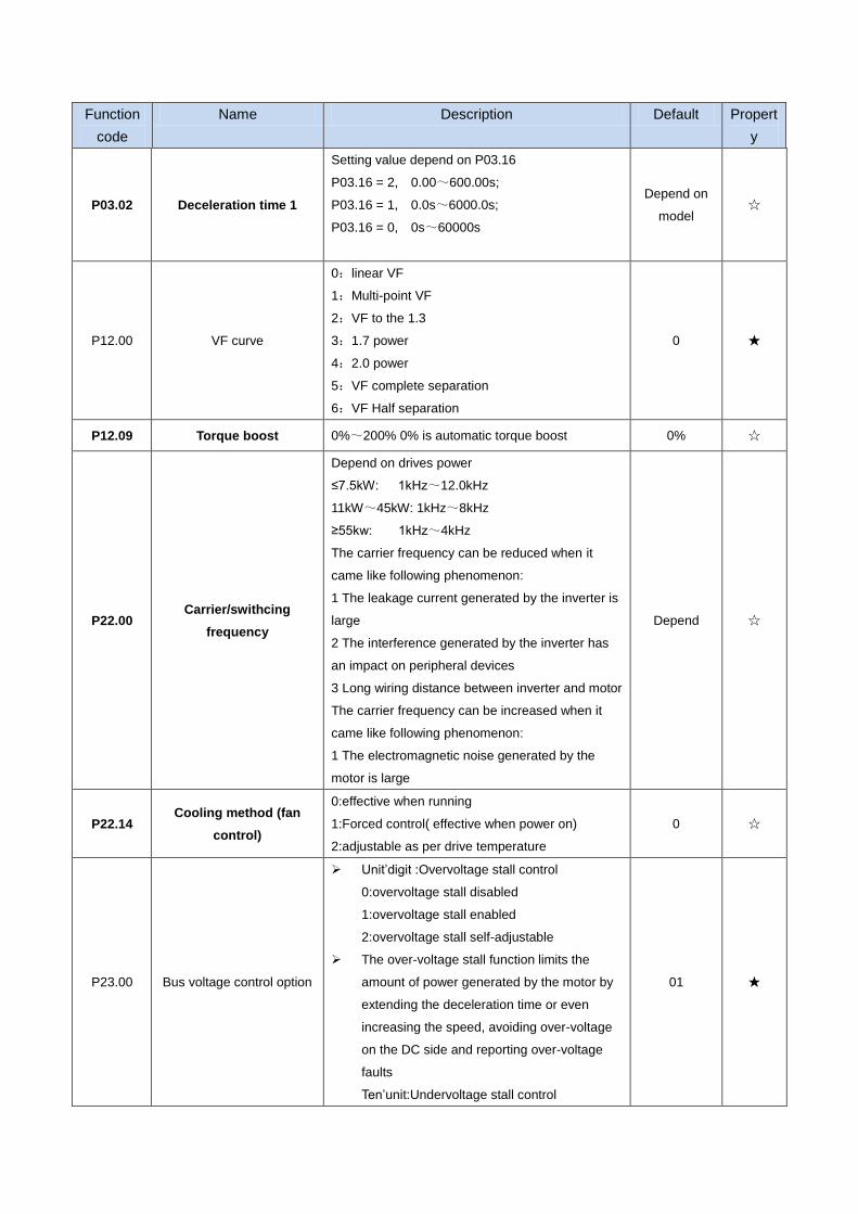
P03.02 Deceleration time 1
Setting value depend on P03.16
P03.16 = 2, 0.00~600.00s;
P03.16 = 1, 0.0s~6000.0s;
P03.16 = 0, 0s~60000s
Depend on
model ☆
P12.00 VF curve
0:linear VF
1:Multi-point VF
2:VF to the 1.3
3:1.7 power
4:2.0 power
5:VF complete separation
6:VF Half separation
0 ★
P12.09 Torque boost 0%~200% 0% is automatic torque boost 0% ☆
P22.00 Carrier/swithcing
frequency
Depend on drives power
≤7.5kW: 1kHz~12.0kHz
11kW~45kW: 1kHz~8kHz
≥55kw: 1kHz~4kHz
The carrier frequency can be reduced when it
came like following phenomenon:
1 The leakage current generated by the inverter is
large
2 The interference generated by the inverter has
an impact on peripheral devices
3 Long wiring distance between inverter and motor
The carrier frequency can be increased when it
came like following phenomenon:
1 The electromagnetic noise generated by the
motor is large
Depend ☆
P22.14 Cooling method (fan
control)
0:effective when running
1:Forced control( effective when power on)
2:adjustable as per drive temperature
0 ☆
P23.00 Bus voltage control option
Unit’digit :Overvoltage stall control
0:overvoltage stall disabled
1:overvoltage stall enabled
2:overvoltage stall self-adjustable
The over-voltage stall function limits the
amount of power generated by the motor by
extending the deceleration time or even
increasing the speed, avoiding over-voltage
on the DC side and reporting over-voltage
faults
Ten’unit:Undervoltage stall control
01 ★

Function
code
Name Description Default Propert
y
0:undervoltage stall disabled
1:undervoltage stall deceleration(decelerate
to zero speed and run at zero speed)
2: undervoltage stall deceleration(decelerate
to zero and stop)
The undervoltage stall function reduces the
motor power consumption or reduces the
power consumption of the motor or turns it
into a power generation operation to avoid
the undervoltage fault on the DC side.
The undervoltage stall function is used when
the input power supply quality is poor (the
power supply voltage fluctuates downward or
the sporadic short power is suspended), and
it is necessary to keep the inverter running as
much as possible.
11 Group Motor 1 Parameter
P11.00 Motor type
0:AC asynchronous motor
1:Synchronous motor(Special software)
See appendix parameter
0 ●
P11.02 Motor rated power
0.1kW~800.0kW
when power is less than 1kw ,0.75kw set to
0.8 as per round up principle ,0.55kw motor
set 0.6
when change motor rated power,AC drive will
automatically set other parameter of motor
name plate and motor model parameter be
careful to use
Depend ★
P11.03 Motor rated voltage 10V~2000V Depend ★
P11.04 Motor rated current P11.02<30kW:0.01A
P11.02>=30kW:0.1A Depend ★
P11.05 Motor rated frequency 1.00Hz~600.00Hz 50.00Hz ★
P11.06 Motor rated RPM 1~60000rpm Depend ★
P11.07 Motor rated power factor 0.500~1.000 Depend ★
r11.08 Motor rated torque Read only,0.1Nm(P11.02<30KW);
1Nm(P11.02>30KW) - ●
r11.09 Number of motor 1 pairs of
pole
Read only,It will auto calculate as per motor rated
frequency and rated rotating speed - ●
P11.10 Auto-tune/self-learning
0:no auto tuning
1:Stationary auto tuning of Asynchronous motor
2:Rotational auto tuning of Asynchronous motor
0 ★

Chapter 5 Fault Diagnosis and Solution
VFD500-PV inverter has 24 types of warning information and protection function. In case of abnormal
fault,the protection function will be invoked, the inverter will stop output, and the faulty relay contact of the
inverter will start, and the fault code will be displayed on the display panel of the inverter. Before consulting
the service department, the user can perform self-check according to the prompts of this chapter, analyze
the fault cause and find out solution. If the fault is caused by the reasons as
described in the dotted frame, please consult the agents of inverter or factory directly.
Fault Name Display Possible Causes Solutions
Inverter unit
protection Er. SC
1: The output circuit is grounded or
short circuited.
2: The connecting cable of the motor is
too long.
3: The IGBT overheat.
4: The internal connections become
loose.
5: The main control board is faulty.
6: The drive board is faulty.
7: The inverter IGBT is faulty.
1: Eliminate external faults.
2: Install a reactor or anoutput
filter.
3: Check the air filter and the
cooling fan.
4: Connect all cables properly.
5: Ask for technical support
6: Ask for technical support
7: Ask for technical support
Ground short circuit Er.SC1
1. Short circuit of motor to ground
2, the motor and inverter wiring is too long
3, module overheating
4. The internal wiring of the inverter is
loose
5. Control board is fault
6, Drive board is fault
7, inverter module is fault
1. Replace cable or motor
2. Install reactor or output filter
3. Check whether the air duct is
blocked, the fan is working properly
and eliminate the existing problems
4. Plug in all the connections
5. Ask for technical support
6. Ask for technical support
7. Ask for technical support
Over current
during
acceleration
Er.OC1
1: The output circuit is grounded or
short circuited.
2: Motor auto-tuning is not performed.
3: The acceleration time is too short.
4: Manual torque boost or V/F curve is
not appropriate.
5: The voltage is too low.
6: The startup operation is performed
on the rotating motor.
7: A sudden load is added during
acceleration.
8: The frequency inverter model is of
too small power class.
1: Eliminate external faults.
2: Perform the motor auto-
Tuning in cold state
3: Increase the acceleration
time.
4: Adjust the manual torque
boost or V/F curve.
5: Adjust the voltage to normal
range.
6: Select rotational speed
tracking restart or start the
motor after it stops.
7: Remove the added load.
8: Select a frequency inverter
Ofhigher power class.
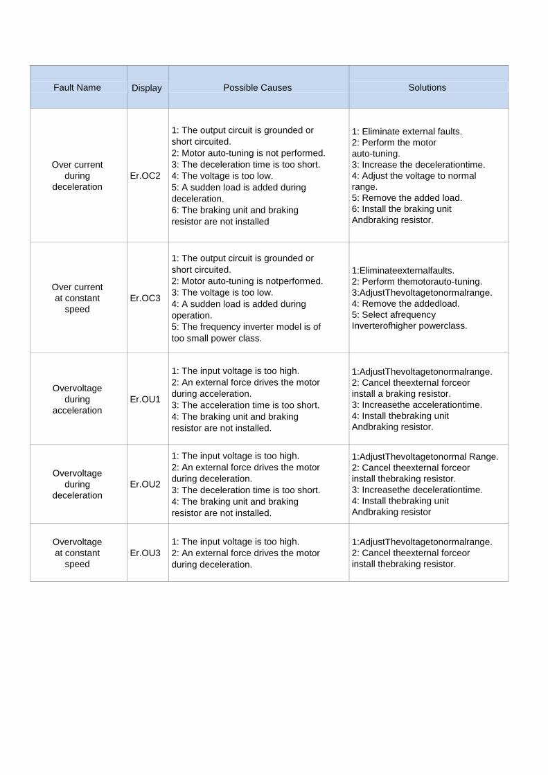
Fault Name Display Possible Causes Solutions
Over current
during
deceleration
Er.OC2
1: The output circuit is grounded or
short circuited.
2: Motor auto-tuning is not performed.
3: The deceleration time is too short.
4: The voltage is too low.
5: A sudden load is added during
deceleration.
6: The braking unit and braking
resistor are not installed
1: Eliminate external faults.
2: Perform the motor
auto-tuning.
3: Increase the decelerationtime.
4: Adjust the voltage to normal
range.
5: Remove the added load.
6: Install the braking unit
Andbraking resistor.
Over current
at constant
speed
Er.OC3
1: The output circuit is grounded or
short circuited.
2: Motor auto-tuning is notperformed.
3: The voltage is too low.
4: A sudden load is added during
operation.
5: The frequency inverter model is of
too small power class.
1:Eliminateexternalfaults.
2: Perform themotorauto-tuning.
3:AdjustThevoltagetonormalrange.
4: Remove the addedload.
5: Select afrequency
Inverterofhigher powerclass.
Overvoltage
during
acceleration
Er.OU1
1: The input voltage is too high.
2: An external force drives the motor
during acceleration.
3: The acceleration time is too short.
4: The braking unit and braking
resistor are not installed.
1:AdjustThevoltagetonormalrange.
2: Cancel theexternal forceor
install a braking resistor.
3: Increasethe accelerationtime.
4: Install thebraking unit
Andbraking resistor.
Overvoltage
during
deceleration
Er.OU2
1: The input voltage is too high.
2: An external force drives the motor
during deceleration.
3: The deceleration time is too short.
4: The braking unit and braking
resistor are not installed.
1:AdjustThevoltagetonormal Range.
2: Cancel theexternal forceor
install thebraking resistor.
3: Increasethe decelerationtime.
4: Install thebraking unit
Andbraking resistor
Overvoltage
at constant
speed
Er.OU3
1: The input voltage is too high.
2: An external force drives the motor
during deceleration.
1:AdjustThevoltagetonormalrange.
2: Cancel theexternal forceor
install thebraking resistor.
Fault Name Display Possible Causes Solutions
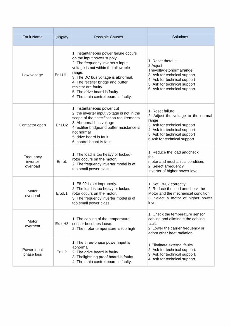
Low voltage Er.LU1
1: Instantaneous power failure occurs
on the input power supply.
2: The frequency inverter's input
voltage is not within the allowable
range.
3: The DC bus voltage is abnormal.
4: The rectifier bridge and buffer
resistor are faulty.
5: The drive board is faulty.
6: The main control board is faulty.
1: Reset thefault.
2:Adjust
Thevoltagetonormalrange.
3: Ask for technical support
4: Ask for technical support
5: Ask for technical support
6: Ask for technical support
Contactor open Er.LU2
1. Instantaneous power cut
2, the inverter input voltage is not in the
scope of the specification requirements
3. Abnormal bus voltage
4,rectifier bridgeand buffer resistance is
not normal
5, drive board is fault
6. control board is fault
1. Reset failure
2. Adjust the voltage to the normal
range
3. Ask for technical support
4. Ask for technical support
5. Ask for technical support
6.Ask for technical support
Frequency
inverter
overload
Er. oL
1: The load is too heavy or locked-
rotor occurs on the motor.
2: The frequency inverter model is of
too small power class.
1: Reduce the load andcheck
the
motor and mechanical condition.
2: Select afrequency
Inverter of higher power level.
Motor
overload Er.oL1
1: F8-02 is set improperly.
2: The load is too heavy or locked-
rotor occurs on the motor.
3: The frequency inverter model is of
too small power class.
1: Set F8-02 correctly.
2: Reduce the load andcheck the
Motor and the mechanical condition.
3: Select a motor of higher power
level
Motor
overheat Er. oH3
1: The cabling of the temperature
sensor becomes loose.
2: The motor temperature is too high
1: Check the temperature sensor
cabling and eliminate the cabling
fault.
2: Lower the carrier frequency or
adopt other heat radiation
Power input
phase loss Er.iLP
1: The three-phase power input is
abnormal.
2: The drive board is faulty.
3: Thelightning proof board is faulty.
4: The main control board is faulty.
1:Eliminate external faults.
2: Ask for technical support.
3: Ask for technical support.
4: Ask for technical support.
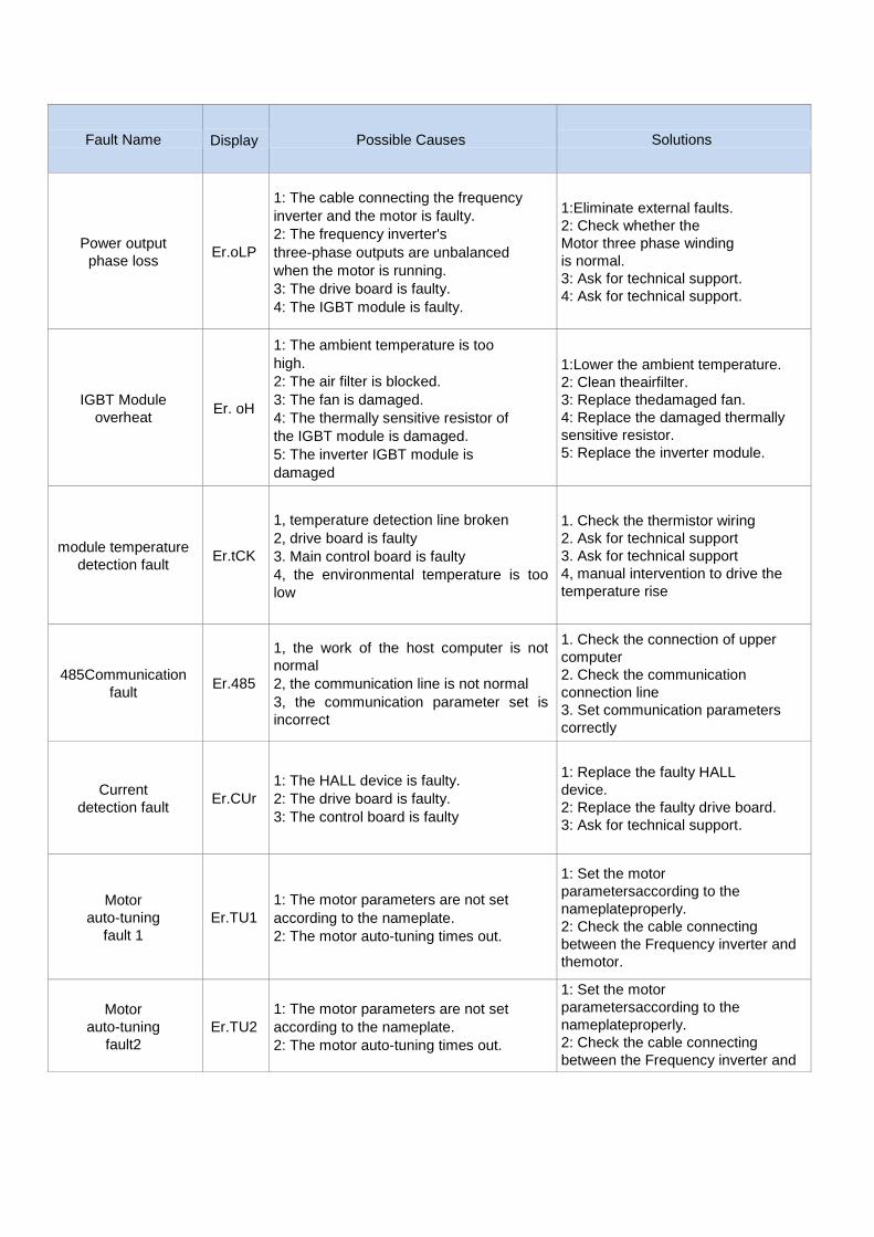
Fault Name Display Possible Causes Solutions
Power output
phase loss Er.oLP
1: The cable connecting the frequency
inverter and the motor is faulty.
2: The frequency inverter's
three-phase outputs are unbalanced
when the motor is running.
3: The drive board is faulty.
4: The IGBT module is faulty.
1:Eliminate external faults.
2: Check whether the
Motor three phase winding
is normal.
3: Ask for technical support.
4: Ask for technical support.
IGBT Module
overheat Er. oH
1: The ambient temperature is too
high.
2: The air filter is blocked.
3: The fan is damaged.
4: The thermally sensitive resistor of
the IGBT module is damaged.
5: The inverter IGBT module is
damaged
1:Lower the ambient temperature.
2: Clean theairfilter.
3: Replace thedamaged fan.
4: Replace the damaged thermally
sensitive resistor.
5: Replace the inverter module.
module temperature
detection fault Er.tCK
1, temperature detection line broken
2, drive board is faulty
3. Main control board is faulty
4, the environmental temperature is too
low
1. Check the thermistor wiring
2. Ask for technical support
3. Ask for technical support
4, manual intervention to drive the
temperature rise
485Communication
fault Er.485
1, the work of the host computer is not
normal
2, the communication line is not normal
3, the communication parameter set is
incorrect
1. Check the connection of upper
computer
2. Check the communication
connection line
3. Set communication parameters
correctly
Current
detection fault Er.CUr
1: The HALL device is faulty.
2: The drive board is faulty.
3: The control board is faulty
1: Replace the faulty HALL
device.
2: Replace the faulty drive board.
3: Ask for technical support.
Motor
auto-tuning
fault 1
Er.TU1
1: The motor parameters are not set
according to the nameplate.
2: The motor auto-tuning times out.
1: Set the motor
parametersaccording to the
nameplateproperly.
2: Check the cable connecting
between the Frequency inverter and
themotor.
Motor
auto-tuning
fault2
Er.TU2
1: The motor parameters are not set
according to the nameplate.
2: The motor auto-tuning times out.
1: Set the motor
parametersaccording to the
nameplateproperly.
2: Check the cable connecting
between the Frequency inverter and
themotor.

Fault Name Display Possible Causes Solutions
EEPROM
read- write
fault
Er.EEP 1、 Eeprom Operate too frequent
2、 The EEPROM chip is damaged.
1、 Operate Eeprom suitable
2、 Replace the main control board
Off load Er. LL 1、The frequency inverter running currentis
lower than the setting value.
1、Confirm whether the load is off
2、Check that the load is
disconnected or the parameter
setting is correct
PID feedback
lost during
running
Er.FbL
1、 PID feedback<P40.35 setting value
and P40.36 not zero,PID
feedback>P40.37 setting value and
P40.38 not zero
1、 check PID feedback signal
2、 P40.35 and P40.37 set correct
parameter
User-defined
fault 1 Er.Ud1
1: The signal of user-defined fault 1 is
input via DI.
2:The signal of user-defined fault 1 is
input via virtual I/O.
1: Reset the operation.
2: Reset the operation
User-defined
fault 2 Er.Ud2
1: The signal of user-defined fault 2 is
input via DI.
2:The signal of user-defined fault 2 is
input via virtual I/O.
1: Reset the operation.
2: Reset the operation
By wave
current
limitingfault
Er.CbC
1: The load is too heavy or locked-
rotor occurs on the motor.
2: The frequency inverter model is of
too small power class
1: Reduce the load and check
the motor and mechanical
condition.
2: Select a frequency inverter of
higher power class.
Too large
speed
deviation
Er.DEV
1: The encoder parameters are
setincorrectly.
2: The motor auto-tuning is notperformed.
3: The detection parameters of toolarge
speed deviation are setincorrectly.
1: Set the encoder parameters
properly.
2: Perform the motor auto-tuning.
3: Set the detection parameters
correctly based on the
actualsituation.
Motor
over-speed Er. oS
1: The encoder parameters are
setincorrectly.
2: The motor auto-tuning is notperformed.
3: The over-speed detectionparameters
are set incorrectly
1: Set the encoder
parametersproperly.
2: Perform the motor auto-tuning.
3: Set the over-speed detection
parameter correctly based on the
actual situation.
Encoder offline Er.PGL
1. motor locked
2. encoder pulse setting wrong
3. encoder offline
1 check motor and mechanical
condition
2 set correct parameter for encoder
3 check encoder connecting line