Solar powered water supply system
23
DESIGN DOCUMENT FOR SOLAR POWER DRIVEN WATER SUPPLY SCHEME IN LORENKACHEW CLUSTER INNYANGATOM DISTRICT By:- Fasil Ayele Design
-
Upload
fasil-ayele -
Category
Engineering
-
view
422 -
download
5
description
Design for solar powered water supply system for Nyangatom District, South Omo zone Ethiopia. The design scope included solar resource determination, load calculation product selection and impelementation methodology.
Transcript of Solar powered water supply system

DESIGNDOCUMENT
FORSOLARPOWER
DRIVENWATER
SUPPLYSCHEMEIN
LORENKACHEW
CLUSTER
INNYANGATOM
DISTRICT
By:- Fasil Ayele
Design

Contents Executive summary ....................................................................................................................................... 2
Design Document for Solar power driven water supply scheme in Lorenkachew cluster in Nyangatom
District ........................................................................................................................................................... 3
Solar Resource .......................................................................................................................................... 3
Pump selection.......................................................................................................................................... 4
Selected Pump specification ................................................................................................................. 6
Controller Selection .................................................................................................................................. 6
CC2000 Controller ................................................................................................................................. 6
Controller Specifications ....................................................................................................................... 7
PV sizing .................................................................................................................................................... 8
Selected PV Module .............................................................................................................................. 9
Sizing Array( Array configuration) ........................................................................................................... 12
Array Mounting Method ......................................................................................................................... 13
Mounting Orientation ......................................................................................................................... 13
Mounting structure ............................................................................................................................. 14
Foundation .............................................................................................................................................. 15
Sizing Cabling .......................................................................................................................................... 15
Pipe sizing ................................................................................................................................................ 16
Water level sensors and pump controls ................................................................................................. 16
Float switch () (open on rise) .............................................................................................................. 17
Float switch (ss100 water sensor) (close on rise) ............................................................................... 17
ss100 water sensor ............................................................................................................................. 17
System Connection Diagram ................................................................................................................... 17
Grounding ............................................................................................................................................... 18
Lightening Protection .............................................................................................................................. 18
Design Revision and designed system capacity ...................................................................................... 19
Power supply circuit ............................................................................................................................ 19
Pump delivery ..................................................................................................................................... 19
Reservoir size recommendation ............................................................................................................. 20

Executive summary
The Nyanngatom territory is located in the south Omo zone, consisting a community of about
20, 000 people. The Nyangatom area is a dry and hot in the very south of the country
bordering Kenya. The area is situated at 360 m.a.s.l. The annual precipitation in the area is
estimated to be about 400mm. The communities’ livihood depends on livestock as well as
agriculture.
The district is located at 4.681N, 35.946E on the globe.

Design Document for Solar power driven
water supply scheme in Lorenkachew cluster
in Nyangatom District
Solar Resource The Nyangatom District is popular for low rain regions in Ethiopia and dry most of the time throughout the year.
Theoretically from its location on the glob, i.e 4.6810
Latitude and 35.9460E which is a region believed to be the
solar belt, it is not wrong to estimate a productive solar system.
According to the data we have collected from Homer Energy website, the solar data for the specified location
shows same
Clearness Daily Radiation
Month Index (kWh/m2/d)
January 0.645 6.136
February 0.619 6.199
March 0.6 6.244
April 0.529 5.54
May 0.549 5.526
June 0.583 5.722
July 0.56 5.503
August 0.609 6.212
September 0.619 6.405

October 0.603 6.074
November 0.63 6.038
December 0.661 6.145
Let us select Design month to be July, because that is the worst solar resource month in the location.
Water Demand for the Lorenkachew Kebele is 15,000 litres per day
Therefore with the design month insolation Peak sun hours (PSH) is 5.503 perday
With the available solar resource we can pump
���� ��� ����� � ������� =����� �� ����� � ���
PSH per day x
hr
60min
���� ��� ����� � ������� =%&'''
&.&') x
*+
,'= 45 litres per minute
Pump selection
The contracting Authority recommends SC series pumps. We also recommend using SC series pumps for the
following reasons.
1. SD series pumps need diaphragm replacement yearly
2. SC series pumps are able to pump higher volume of water
3. SC series pumps are capable of pumping from greater depth.
4. SC series pumps are best suitable for village water supply and this is a village water supply project
The pump we supply is from Kyocera
For selecting the surface pumps we need to determine Flow rate per minute and the total dynamic height
Determining total dynamic head
The total dynamic head of a water system must be considered when determining the size of pumping equipment
to be installed. It determines the various head losses that the pump must overcome.
Total dynamic head= elevation head + friction head loss + pressure head
Using the following data from the given specification to TDH calculator
Specifications
1. Pump flow rate =45 lt/min
2. Pipe diameter =1.25 inch
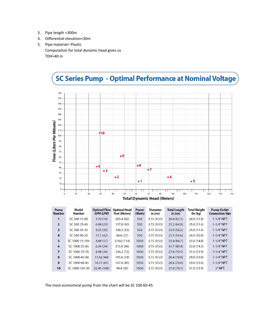
3. Pipe length =300m
4. Differential elevation=30m
5. Pipe material= Plastic
Computation for total dynamic head gives us
TDH=40 m
The most economical pump from the chart will be SC 100 60-45.

Selected Pump specification
Model Optimal
flow
LPM
OPTIMAL
HEAD m
POWER
watt
Pump
outlet
connection
size
Nominal
voltage for
optimal
operation
SC 100 60-45 61 45 1050 1-1/4” NPT 120
About the selected pump
The Kyocera SC Series solar pumps are high quality, Maintenance free, DC powered pumps specially
designed for water delivery in remote locations
SC 100 60-45 operate on 1000 watts of direct current and 120Vdc. The power may be supplied from a
variety of independent sources including solar modules and/ batteries.
The motors are state of Art, brushless DC, permanent magnet type constructed from marine grade bronze
and 304 stainless steel
Controller Selection
Like the contracting Authority we recommend utilization of CC2000 controller
CC2000 Controller
• The CC 2000 pump controller is designed to connect solar modules to Kyocera Solar’s SC series
submersible motors and centrifugal pumps.
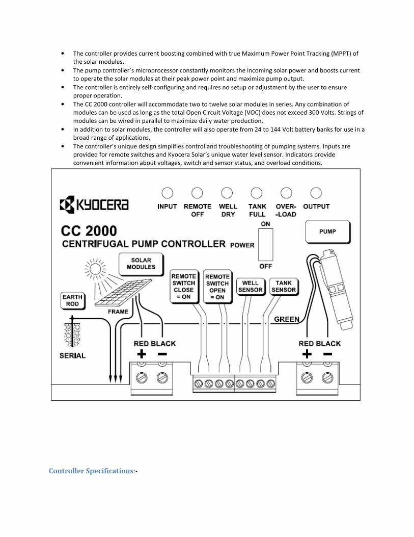
• The controller provides current boosting combined with true Maximum Power Point Tracking (MPPT) of
the solar modules.
• The pump controller’s microprocessor constantly monitors the incoming solar power and boosts current
to operate the solar modules at their peak power point and maximize pump output.
• The controller is entirely self-configuring and requires no setup or adjustment by the user to ensure
proper operation.
• The CC 2000 controller will accommodate two to twelve solar modules in series. Any combination of
modules can be used as long as the total Open Circuit Voltage (VOC) does not exceed 300 Volts. Strings of
modules can be wired in parallel to maximize daily water production.
• In addition to solar modules, the controller will also operate from 24 to 144 Volt battery banks for use in a
broad range of applications.
• The controller’s unique design simplifies control and troubleshooting of pumping systems. Inputs are
provided for remote switches and Kyocera Solar’s unique water level sensor. Indicators provide
convenient information about voltages, switch and sensor status, and overload conditions.
Controller Specifications:-

PV sizing The PV sizing is based on the power requirement of the pump system and nominal voltage of the pump.
Nominal Voltage of the Pump= 120V
Power rating of the pump is =1050W
Pump manufacturer recommendation in sizing the PV
1. Depending on the size and number of solar modules, the array configuration, the array
mounting, location and time of year, the pump will produce the optimal flow for 2 to 8
hours per day. Kyocera suggests multiplying pump power watts by 1.16 to derive PV
watts required at STC.
2. Optimal performance above is based on nominal PV voltage of 120V for SC 1000 Series.
Therefore the size of our PV will be= 1.16*1050=1218W
The other important factor in sizing PV is the ambient temperature of the area. Because at PV cell output greatly
decreases with increase in module temperature. Usually cell temperatures are greater than environmental
temperature. And the NOCT (Nominal operating cell temperature) at a nominal temperature of 200c is 45
0c for the
selected product.

Selected PV Module

The selected location is in the solar belt and irradiance can be taken as 800w/m2
for ensuring maximum result.

The temperature at the peak sun hours in the location according to
M e a n d a i l y m a x i m u m t e m p e r a t u r e f o r c o n t r o l
p e r i o d ( 1 9 6 1 - 1 9 9 0 ) , i n t e r m e d i a t e p e r i o d ( 2 0 2 1 -
2 0 5 0 ) a n d f a r f u t u r e ( 2 0 7 0 - 2 0 9 9 ) d o w n s c a l e d u s i n g
H a d G M C 3 f o r c i n g a n d B 2 e m i s s i o n s c e n a r i o f o r J i n k a
s t a t i o n .
From the above graph we can understand that the average peak sun hour temperature in the area is about 27
0C.
We shall determine the cell temperature to calculate PV sizing.
Cell temperature can be determined using
We have the following parameters from the above explanations
TAir=270
C
NOCT=450
C
s=80mw/cm2
Therefore, Tcell=520C
Now using the temperature coefficient for the selected Pannel
From the datasheet of the product we can see that under Nominal cell operating conditions the output of the
module was 230W
Now for a module temperature of 520C and temperature cooefficient of -0.45%/
0c, the module output will be

Pdc,PTC = 230W[1 − 0.0045(52 − 45)] = 223 W
Sizing Array( Array configuration) The system voltage for the pump is given to be 120V for optimal operation
Therefore the number of module in one string will be,
M=120/35=3.42=3
We have selected 3 modules in a string because the normal operating voltage of the pump is between 30-120V
The power output from a string is p=V x I=105 x 6.4=672W
It is calculated Above that the PV should supply the load a total power of 1218w
Therefore we are expected to have n strings
N=1218/672=1.8125=2
For system voltage similarly using the temperature coefficient
Vdc,PTC = 36.1V[1 − 0.0051(52 − 45)] = 35V
The total system therefor will have two strings each having three modules. Therefore we need 6 modules of the
specified type for the project.

Array Mounting Method We can adopt two kinds of array mounting configuration Fixed mounting and tracking mount. The tracking mount
is a mounting arrangement that provides us the best solar resource utilization. However, we will adopt Fixed
mounted arrangement for this project for the following reasons
1. The place is a very remote place and installation that does not require frequent maintenance is a wise
choice
2. The location is under the sun belt so fixed arrangement of mounting still gives a good performance
Mounting Orientation
The mounting structure will be oriented to the south at 4.68 degree tilted.

Mounting structure
Frame structure
The frame structure for locating the PV modules is constructed from L-profile and T-profile 20x20x2mm steel
profile.
All joints are made of High carbon welding
Stand structure
The stand structure is made of 30x30x2.5mm RHS steel.

Foundation
On the location where the stand is to be installed we should avoid growth of any vegetation as it may result in
shading effects later when grown.
Therefore, the Area which is 6.5m x 9.5 m will be cleared excavated to a depth of 60cm. selects compacting will be
made to the bottom 20cm height and the remaining will be filled with C-25 concrete.
Anchors to mounting the stand structure will be buried under the concrete.
Sizing Cabling
The proper sizing of an electrical (load bearing) cable is important to ensure that the cable can:
• Operate continuously under full load without being damaged
• Withstand the worst short circuits currents flowing through the cable
• Provide the load with a suitable voltage (and avoid excessive voltage drops)
• (optional) Ensure operation of protective devices during an earth fault
The following data must be known for selecting cable size for DC systems
1 - Percentage cable loss acceptable: - Up to 2% loss can be tolerable to make the cabling cost reasonable for the
specified project
2 - System voltage: - our maximum system voltage is 120Vdc
3 – Maximum current (amps) to be carried by the cable =12A
4 - Length of cable run required 100m.
Using these data we can select a cable size using appropriate standards.
Accordingly, the cable size will be 25mm2
Yet the controller input for solar and pump shows that the maximum cable diameter is 16mm2 so we will select
16mm2. This in turn results the drop in the cable to about 3%.
The cable type we have selected is 2*16mm2 PVC insulated PVC sheath power cable Pure Copper
Conductor

Pipe sizing The piping between the pump and reservoir is selected to be 1-1/4”NPT plastic pipe.
Because the selected pump outlet connection size is same.
Material 1. PVC
2. Cotton Polyester Yarns
3. Calcarea
4. Oil
Grade (Quality ) Excellent Techniques & Super Quality & Standard Quality
Working Pressure
2 bar, 3 bar, 4 bar, 5 bar, 6 bar, 7 bar and 8 bar. (1bar = 14.5 psi )
Size
1.25 inch
Features
1. Light weight, good flexibility, bright color, smooth layer. Hongfei hose.
2. Roll flat and easy for take back, convenient for moving and none limit of length..
Hongfei hose.
3. It is capable of keeping the flexibility and elasticity in the low-temperature water.
Hongfei hose.
4. It is Anti-high pressure, corrosion resistance and ageing resistance. Hongfei hose.
Water level sensors and pump controls The water level sensor control of pump operation depending water levels. Adopting these sensors in to the system helps:
1. To avoid dry running of the pump in cases of low water level of the river 2. To avoid over flowing of water when the reservoir is full.
For both operations we select to use SS100 water level sensor. However the mode of operation for the above two functions is different.

Float switch () (open on rise)
This sensor is used in the reservoir or water tank. The principle of operation is that the water level gets
higher and the reservoir is almost full, the float switch gets higher and it open circuit. Therefore the
pump stops pumping.
Float switch (ss100 water sensor) (close on rise)
This sensor is used in the river or water well. The principle of operation is that the water level low and
the well or river is almost empty or too low for pumping, the float switch gets lower and it opens circuit.
Therefore the pump stops pumping. And when the water level rises the switch closes and the pump
starts to pump.
ss100 water sensor
Installed near the pump to protect the pump from dry running
System Connection Diagram
Off position
On position
Pipe
Float switch to controller
Float switch to controller
CC2000
PV Array
Float switches
Open Rise
Op
SS100
SC 100 60-45

Grounding
It is wise to ground /earth Electrical system for giving fault current an alternative path to flow through.
Pure copper grounding bar will be installed and every metallic body of the system will be grounded.
Lightening Protection
As an expensive set of Equipment in the project we should design it a lightening protection system.

Design Revision and designed system capacity
Power supply circuit
Pump delivery
The pump optimal flow rate is 61 litres / minute
With the practical irradiance of 800w/m2 the design month peak sun hours will be 4hrs. Therefore the
pump can supply
Supply of water (Litre per day) = 61Lpm x 4hrs/day x 60m/hr=14640 Litre per day.

In the worst scenario our pump can supply 14,640 Litres per day.
However, the location average practical peak sun hours is 5 (5.93 at 1000w/m2 irradiance)
Supply of water (Litre per day) = 61Lpm x 5hrs/day x 60m/hr=18300 Litre per day.
The average amount of water the pump can deliver a day therefor is 18300litres per day.
The pump selection has also provided a very positive result so the system can be implemented.
Reservoir size recommendation
It is very practical that solar systems face cloudy days where they cannot perform well. So to insure
maximum security of supply the reservoir capacity should be 45,000 liters. This ensures three days of
storage.