Solar Power Satellites, Space Elevator, and Reusable … · Solar Power Satellites, Space Elevator,...
7
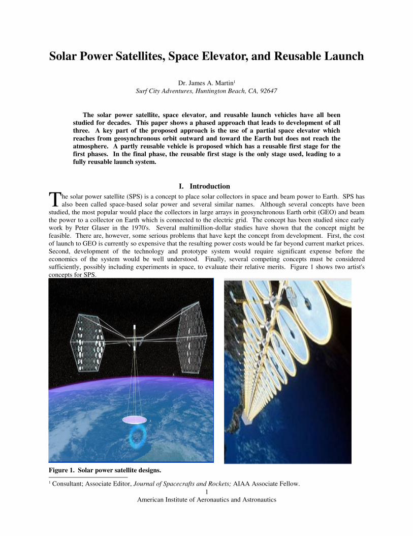
Solar Power Satellites, Space Elevator, and Reusable Launch Dr. James A. Martin 1 Surf City Adventures, Huntington Beach, CA, 92647 The solar power satellite, space elevator, and reusable launch vehicles have all been studied for decades. This paper shows a phased approach that leads to development of all three. A key part of the proposed approach is the use of a partial space elevator which reaches from geosynchronous orbit outward and toward the Earth but does not reach the atmosphere. A partly reusable vehicle is proposed which has a reusable first stage for the first phases. In the final phase, the reusable first stage is the only stage used, leading to a fully reusable launch system. I. Introduction he solar power satellite (SPS) is a concept to place solar collectors in space and beam power to Earth. SPS has also been called space-based solar power and several similar names. Although several concepts have been studied, the most popular would place the collectors in large arrays in geosynchronous Earth orbit (GEO) and beam the power to a collector on Earth which is connected to the electric grid. The concept has been studied since early work by Peter Glaser in the 1970's. Several multimillion-dollar studies have shown that the concept might be feasible. There are, however, some serious problems that have kept the concept from development. First, the cost of launch to GEO is currently so expensive that the resulting power costs would be far beyond current market prices. Second, development of the technology and prototype system would require significant expense before the economics of the system would be well understood. Finally, several competing concepts must be considered sufficiently, possibly including experiments in space, to evaluate their relative merits. Figure 1 shows two artist's concepts for SPS. T Figure 1. Solar power satellite designs. 1 Consultant; Associate Editor, Journal of Spacecrafts and Rockets; AIAA Associate Fellow. American Institute of Aeronautics and Astronautics 1
Transcript of Solar Power Satellites, Space Elevator, and Reusable … · Solar Power Satellites, Space Elevator,...
Solar Power Satellites, Space Elevator, and Reusable Launch
Dr. James A. Martin1
Surf City Adventures, Huntington Beach, CA, 92647
The solar power satellite, space elevator, and reusable launch vehicles have all been
studied for decades. This paper shows a phased approach that leads to development of all
three. A key part of the proposed approach is the use of a partial space elevator which
reaches from geosynchronous orbit outward and toward the Earth but does not reach the
atmosphere. A partly reusable vehicle is proposed which has a reusable first stage for the
first phases. In the final phase, the reusable first stage is the only stage used, leading to a
fully reusable launch system.
I. Introduction
he solar power satellite (SPS) is a concept to place solar collectors in space and beam power to Earth. SPS has
also been called space-based solar power and several similar names. Although several concepts have been
studied, the most popular would place the collectors in large arrays in geosynchronous Earth orbit (GEO) and beam
the power to a collector on Earth which is connected to the electric grid. The concept has been studied since early
work by Peter Glaser in the 1970's. Several multimillion-dollar studies have shown that the concept might be
feasible. There are, however, some serious problems that have kept the concept from development. First, the cost
of launch to GEO is currently so expensive that the resulting power costs would be far beyond current market prices.
Second, development of the technology and prototype system would require significant expense before the
economics of the system would be well understood. Finally, several competing concepts must be considered
sufficiently, possibly including experiments in space, to evaluate their relative merits. Figure 1 shows two artist's
concepts for SPS.
T
Figure 1. Solar power satellite designs.
1 Consultant; Associate Editor, Journal of Spacecrafts and Rockets; AIAA Associate Fellow.
American Institute of Aeronautics and Astronautics
1

The space elevator is also a concept that has been studied for decades. It has also been called gravity ladder and
beanstalk. The most common concept would have a part of the system in GEO, with arms extending into space and
toward Earth. The arm away from Earth usually ends in a counterweight. The arm extending toward Earth usually
ends at a point on the equator. Figure 2 shows some design concepts. As with the SPS, there are some problems
with the space elevator concept. The most serious is that there is no existing material that has a sufficient strength-
to-density ratio. Where the space elevator passes through the atmosphere, there could be serious interactions. Debris
and satellites, especially in low Earth orbit (LEO), could sever the space elevator.
Figure 2. Space elevator designs.
Reusable launch vehicles (RLVs) have long been studied; many believe they are the future path to lower-cost
access to space. They could also provide increased safety, reliability, and rapid response as needs arise. Some
concepts are shown in Figure 3. As with the SPS and space elevator, the RLV has some difficulties that have led to
delays in its development. The primary problem is that the economics are reasonable only for high traffic rates. At
the same time, those markets that would provide high traffic rates, such as SPS and tourism, will only develop after
launch costs are reduced--the classic chicken-and-egg problem. One way to alleviate this problem is to develop
partly reusable vehicles. The Space Shuttle is the one vehicle that has been developed that has partial re-usability.
While its degree of success has been argued, it has provided launch of people and cargo that is unmatched by
expendable systems.
American Institute of Aeronautics and Astronautics
2
Looking at North Pole
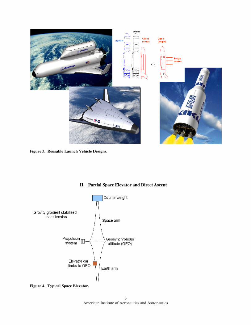
Figure 3. Reusable Launch Vehicle Designs.
II. Partial Space Elevator and Direct Ascent
Figure 4. Typical Space Elevator.
American Institute of Aeronautics and Astronautics
3

The typical space elevator design, as shown in Figure 4, has a central section in orbit at GEO. The Earth arm is
at lower altitude and would need to be moving faster to be in orbit; therefore, it wants to fall and needs to be held in
place by the upper parts. The space arm is at higher altitude and would need to be moving slower to be in orbit;
therefore, it wants to fly off into space and needs to be held by the lower parts. As a result, the space elevator is in
tension and is gravity-gradient stabilized. The space arm could be quite long, but an additional mass is used to
provide the lift to allow it to end at a reasonable distance. As the elevator car climbs up the space elevator, it gains
potential energy and would tend to pull the space elevator downward. It also gains rotation kinetic energy as its
speed around the Earth must increase to keep the rotation at one revolution per day at higher altitudes. The energy
must be supplied to the space elevator by a propulsion system. A solar electric or solar sail system could be used.
Some energy is returned to the elevator when the car goes down for the next payload or carries a payload down, and
a balancing of several cars could be used to minimize the propulsion needs. The propulsion system could be at the
counterweight or several locations; the sketches show it at GEO, but a trade study would be needed.
The bottom of the space elevator must have
enough area for strength to hold the elevator car
and payload. Each section above the bottom
must have enough area to hold the elevator car,
the payload, and the section below it. When the
equations are integrated, the shape is an
exponential, as shown in Ref. 1. Similarly,
beyond GEO, the shape is a decreasing
exponential.
A space elevator between Earth and GEO
requires a material with a very high strength-to-
density ratio. No current material has a high
enough ratio. There is some hope that carbon
nanotubes will have an acceptable ratio and
make the space elevator feasible from Earth to
GEO.
Figure 5. The Earth arm of a space elevator.
The space elevator does not need to extend all the way from GEO to Earth. In Reference 1, a space elevator that
extends only part of the way to the surface of Earth was considered. Using equations derived in Ref. 1 and strength-
to-density ratios of possible near-term materials, the ratio of the area at GEO divided by the area at the bottom has
been plotted in Figure 6 as a function of the radius at
the bottom divided by the radius at GEO, where the
radius is measured from the center of Earth. With a
strength ratio typical of fiberglass, the growth is
dramatic. With the higher strength of graphite
whiskers, the growth is noticeably reduced. To help
with the understanding of the area growth, an
example design is shown in Figure 7 for fiberglass
and a radius ratio of 0.6; that is, the Earth arm
reaches 40% of the distance from GEO to the center
of the Earth. At the bottom, the elevator has a square
shape, 1 cm by 1 cm. At GEO, it has a rectangular
shape, 1 cm by 18 cm. The length over which this
growth takes place is 17,000 km. While such a
design would be large and heavy, it would be
feasible. The primary advantage of the partial space
elevator is that it allows designs appropriate for
existing materials.
Figure 6. The exponential growth of space elevator area ratio.
American Institute of Aeronautics and Astronautics
4
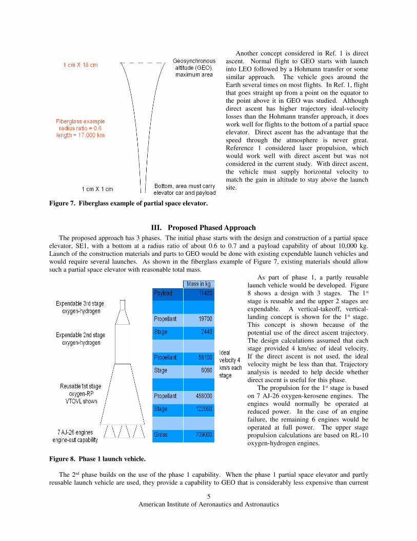
Another concept considered in Ref. 1 is direct
ascent. Normal flight to GEO starts with launch
into LEO followed by a Hohmann transfer or some
similar approach. The vehicle goes around the
Earth several times on most flights. In Ref. 1, flight
that goes straight up from a point on the equator to
the point above it in GEO was studied. Although
direct ascent has higher trajectory ideal-velocity
losses than the Hohmann transfer approach, it does
work well for flights to the bottom of a partial space
elevator. Direct ascent has the advantage that the
speed through the atmosphere is never great.
Reference 1 considered laser propulsion, which
would work well with direct ascent but was not
considered in the current study. With direct ascent,
the vehicle must supply horizontal velocity to
match the gain in altitude to stay above the launch
site.
Figure 7. Fiberglass example of partial space elevator.
III. Proposed Phased Approach
The proposed approach has 3 phases. The initial phase starts with the design and construction of a partial space
elevator, SE1, with a bottom at a radius ratio of about 0.6 to 0.7 and a payload capability of about 10,000 kg.
Launch of the construction materials and parts to GEO would be done with existing expendable launch vehicles and
would require several launches. As shown in the fiberglass example of Figure 7, existing materials should allow
such a partial space elevator with reasonable total mass.
As part of phase 1, a partly reusable
launch vehicle would be developed. Figure
8 shows a design with 3 stages. The 1st
stage is reusable and the upper 2 stages are
expendable. A vertical-takeoff, vertical-
landing concept is shown for the 1st stage.
This concept is shown because of the
potential use of the direct ascent trajectory.
The design calculations assumed that each
stage provided 4 km/sec of ideal velocity.
If the direct ascent is not used, the ideal
velocity might be less than that. Trajectory
analysis is needed to help decide whether
direct ascent is useful for this phase.
The propulsion for the 1st stage is based
on 7 AJ-26 oxygen-kerosene engines. The
engines would normally be operated at
reduced power. In the case of an engine
failure, the remaining 6 engines would be
operated at full power. The upper stage
propulsion calculations are based on RL-10
oxygen-hydrogen engines.
Figure 8. Phase 1 launch vehicle.
The 2nd phase builds on the use of the phase 1 capability. When the phase 1 partial space elevator and partly
reusable launch vehicle are used, they provide a capability to GEO that is considerably less expensive than current
American Institute of Aeronautics and Astronautics
5

expendable launch vehicles. The combination will be used to provide launches to GEO that help to amortize the
cost of developing the system. In particular, at this point some experimental demonstrations of SPS technologies
can be completed.
The major component of phase 2 is a larger and longer partial space elevator, SE2. The length would depend on
the material technology available at the time. With reasonable developments, the bottom could reach down to a
radius ratio of 0.3 to 0.5. The payload capability could be over 30,000 kg.
The launch vehicle for phase 2 is shown in
Figure 9. It is the lower stages of the phase 1
vehicle. The lower 2 stages provide enough
ideal velocity to reach the partial space elevator
at the lower radius. The payload is of course
increased without the upper stage to push. The
33,000 kg payload shown corresponds to the 4
km/sec ideal velocity of each stage and could
change depending on the length of the partial
space elevator. The engine-out capability of the
phase 1 stage 1 is retained.
Figure 9. Phase 2 launch vehicle.
The 3rd phase continues to build on the previous capability. The transportation cost to GEO is considerably
reduced by the elimination of the upper stage costs and the increase in the payload per launch. Any payload going
to GEO or beyond can be carried by the system to amortize costs. The costs are now down enough to allow
construction of the full-sized prototype SPS.
The phase 2 capability is now used for construction of the final partial space elevator, SE3, reaching nearly down
to LEO. The payload of this larger elevator is nearly 100,000 kg, allowing SPS construction from large segments
assembled on Earth. The exponential growth of the elevator with length, shown in Fig. 6, would not allow this
design without significant improvements in materials. Carbon nanotubes are currently the best contenders for such
an improvement. Work has been done on space elevators recently based on the assumption that carbon nanotubes
will make it feasible in the near future.
The launch vehicle for phase 3, shown in
Figure 10, is just the reusable stage from phase
2. Using direct ascent, the single stage can
easily get out of the atmosphere and reach the
bottom of the elevator. With a single stage,
engine-out mission completion, low speeds
through the atmosphere, and a low total vehicle
ideal velocity, the costs and reliability of this
vehicle will be very attractive. With high
traffic rates, the cost per kg to GEO could
approach the cost of long-distance aircraft
transportation.
Figure 10. Phase 3 launch vehicle.
The primary use of the phase 3 capability is the construction of the SPS fleet. As each satellite is completed, it
enters service and begins to amortize the cost of the system development and construction. Additional satellites are
added to match the need for power, which will likely continue to increase.
In addition to the construction of the SPS fleet, the phase 3 capability provides an excellent capability for
exploration and colonization. When vehicles move beyond GEO on the elevator, they are given additional velocity
toward escape of the Earth gravity well. The space elevator is also useful for moving payloads from space to Earth.
They can be placed on the reusable stage at the bottom of the elevator and returned with the vehicle.
American Institute of Aeronautics and Astronautics
6
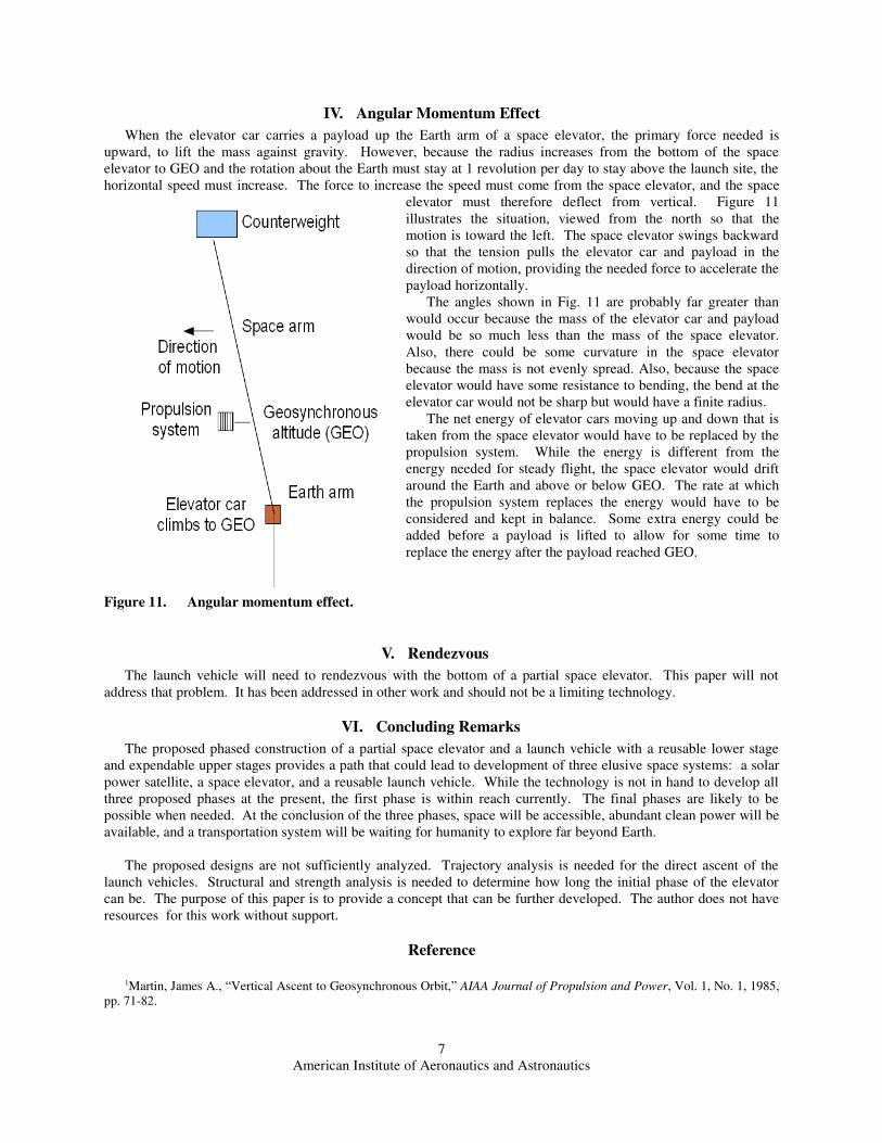
IV. Angular Momentum Effect
When the elevator car carries a payload up the Earth arm of a space elevator, the primary force needed is
upward, to lift the mass against gravity. However, because the radius increases from the bottom of the space
elevator to GEO and the rotation about the Earth must stay at 1 revolution per day to stay above the launch site, the
horizontal speed must increase. The force to increase the speed must come from the space elevator, and the space
elevator must therefore deflect from vertical. Figure 11
illustrates the situation, viewed from the north so that the
motion is toward the left. The space elevator swings backward
so that the tension pulls the elevator car and payload in the
direction of motion, providing the needed force to accelerate the
payload horizontally.
The angles shown in Fig. 11 are probably far greater than
would occur because the mass of the elevator car and payload
would be so much less than the mass of the space elevator.
Also, there could be some curvature in the space elevator
because the mass is not evenly spread. Also, because the space
elevator would have some resistance to bending, the bend at the
elevator car would not be sharp but would have a finite radius.
The net energy of elevator cars moving up and down that is
taken from the space elevator would have to be replaced by the
propulsion system. While the energy is different from the
energy needed for steady flight, the space elevator would drift
around the Earth and above or below GEO. The rate at which
the propulsion system replaces the energy would have to be
considered and kept in balance. Some extra energy could be
added before a payload is lifted to allow for some time to
replace the energy after the payload reached GEO.
Figure 11. Angular momentum effect.
V. Rendezvous
The launch vehicle will need to rendezvous with the bottom of a partial space elevator. This paper will not
address that problem. It has been addressed in other work and should not be a limiting technology.
VI. Concluding Remarks
The proposed phased construction of a partial space elevator and a launch vehicle with a reusable lower stage
and expendable upper stages provides a path that could lead to development of three elusive space systems: a solar
power satellite, a space elevator, and a reusable launch vehicle. While the technology is not in hand to develop all
three proposed phases at the present, the first phase is within reach currently. The final phases are likely to be
possible when needed. At the conclusion of the three phases, space will be accessible, abundant clean power will be
available, and a transportation system will be waiting for humanity to explore far beyond Earth.
The proposed designs are not sufficiently analyzed. Trajectory analysis is needed for the direct ascent of the
launch vehicles. Structural and strength analysis is needed to determine how long the initial phase of the elevator
can be. The purpose of this paper is to provide a concept that can be further developed. The author does not have
resources for this work without support.
Reference
1Martin, James A., “Vertical Ascent to Geosynchronous Orbit,” AIAA Journal of Propulsion and Power, Vol. 1, No. 1, 1985,
pp. 71-82.
American Institute of Aeronautics and Astronautics
7