Solar Photovoltaic (PV) Systems 690 - Mike Holt … technical change that occurred to this section...
12
One technical change that occurred to this section can be found in 690.4(B), which addressed the listing of PV system equipment. Keeping up with new prod- ucts and technologies is a very difficult task when updating the NEC, so you can expect Code changes every time new products come out. The example here is dc combiners and dc-to-dc converters. By adding them to the list of equipment in 690.4(B) they must be listed. There are several changes in Article 690 that are simple relocations. These certainly make the NEC a better document. Examples of this include 690.13 and 690.14 which were condensed into just 690.13 (covering the rules for disconnecting means). Previous editions of the Code had 690.13 covering disconnects, then 690.14 covering “additional provisions” for dis- connecting means! 690.5 Ground-Fault Protection Grounded dc PV arrays must be provided with dc ground-fault protection meeting the requirements of 690.5(A) through (C) to reduce fire hazards. Figure 690–24 (D) Multiple Inverters. Where multiple utility-interactive invert- ers are located remote from each other, a directory is required at each dc PV system disconnecting means, ac disconnecting means for mini- and micro-inverters, and service disconnecting means showing the location of all dc and ac PV system discon- necting means in the building/structure [705.10]. Ex: A directory isn’t required where all PV system disconnecting means are grouped at the service disconnecting means. 2014 CHANGE ANALYSIS: Article 690 might be the most difficult article in the entire Code book through which to navigate. For several years, the requirements in this article didn’t really change that much, then a huge influx of changes occurred due to the sudden popularity of these systems. When a massive volume of changes occur to one article the end result will almost certainly be confusing, with requirements in sections that don’t seem to make much sense. This section is a perfect example of this. Circuit routing and connection requirements were found here in 2011, but are those really “general requirements?” These changes may seem insignificant, but they make this article much easier to use, and therefore were cer- tainly worth making. Figure 690–23 Figure 690–24 339 Mike Holt Enterprises, Inc. • www.MikeHolt.com • 888.NEC.CODE (632.2633) Solar Photovoltaic (PV) Systems | 690.5
Transcript of Solar Photovoltaic (PV) Systems 690 - Mike Holt … technical change that occurred to this section...
One technical change that occurred to this section can be found in 690.4(B), which addressed the listing of PV system equipment. Keeping up with new prod-ucts and technologies is a very difficult task when updating the NEC, so you can expect Code changes every time new products come out. The example here is dc combiners and dc-to-dc converters. By adding them to the list of equipment in 690.4(B) they must be listed.
There are several changes in Article 690 that are simple relocations. These certainly make the NEC a better document. Examples of this include 690.13 and 690.14 which were condensed into just 690.13 (covering the rules for disconnecting means). Previous editions of the Code had 690.13 covering disconnects, then 690.14 covering “additional provisions” for dis-connecting means!
690.5 Ground-Fault Protection
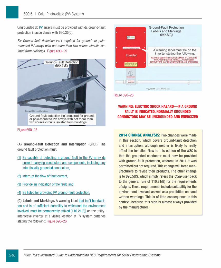
Grounded dc pV arrays must be provided with dc ground-fault protection meeting the requirements of 690.5(A) through (C) to reduce fire hazards. Figure 690–24
(D) Multiple Inverters. Where multiple utility-interactive invert-ers are located remote from each other, a directory is required at each dc pV system disconnecting means, ac disconnecting means for mini- and micro-inverters, and service disconnecting means showing the location of all dc and ac pV system discon-necting means in the building/structure [705.10].
Ex: A directory isn’t required where all PV system disconnecting means are grouped at the service disconnecting means.
2014 CHANGE ANALYSIS: Article 690 might be the most difficult article in the entire Code book through which to navigate. For several years, the requirements in this article didn’t really change that much, then a huge influx of changes occurred due to the sudden popularity of these systems. When a massive volume of changes occur to one article the end result will almost certainly be confusing, with requirements in sections that don’t seem to make much sense. This section is a perfect example of this. Circuit routing and connection requirements were found here in 2011, but are those really “general requirements?” These changes may seem insignificant, but they make this article much easier to use, and therefore were cer-tainly worth making.
Figure 690–23
Figure 690–24
339Mike Holt Enterprises, Inc. • www.MikeHolt.com • 888.NEC.CODE (632.2633)
Solar Photovoltaic (PV) Systems | 690.5
WARNING: ELECTRIC SHOCK HAZARD—IF A GROUND FAULT IS INDICATED, NORMALLY GROUNDED
CONDUCTORS MAY BE UNGROUNDED AND ENERGIZED
2014 CHANGE ANALYSIS: Two changes were made in this section, which covers ground-fault detection and interruption, although neither is likely to really affect the installer. New to this edition of the NEC is that the grounded conductor must now be provided with ground-fault protection, whereas in 2011 it was permitted but not required. This change will force man-ufacturers to revise their products. The other change is to 690.5(C), which simply refers the Code user back to the general rule of 110.21(B) for the requirements of signs. These requirements include suitability for the environment involved, as well as a prohibition on hand written warnings. This is of little consequence in this context, because this sign is almost always provided by the manufacturer.
ungrounded dc pV arrays must be provided with dc ground-fault protection in accordance with 690.35(C).
Ex: Ground-fault detection isn’t required for ground- or pole-mounted PV arrays with not more than two source circuits iso-lated from buildings. Figure 690–25
(A) Ground-Fault Detection and Interruption (GFDI). The ground fault protection must:
(1) Be capable of detecting a ground fault in the pV array dc current-carrying conductors and components, including any intentionally grounded conductors,
(2) Interrupt the flow of fault current,
(3) provide an indication of the fault, and,
(4) Be listed for providing pV ground-fault protection.
(C) Labels and Markings. A warning label that isn’t handwrit-ten and is of sufficient durability to withstand the environment involved, must be permanently affixed [110.21(B)] on the utility- interactive inverter at a visible location at pV system batteries stating the following: Figure 690–26
Figure 690–25
Figure 690–26
Mike Holt’s Illustrated Guide to Understanding NEC Requirements for Solar Photovoltaic Systems340
690.5 | Solar Photovoltaic (PV) Systems
Part II. Circuit Requirements
690.7 Maximum Voltage
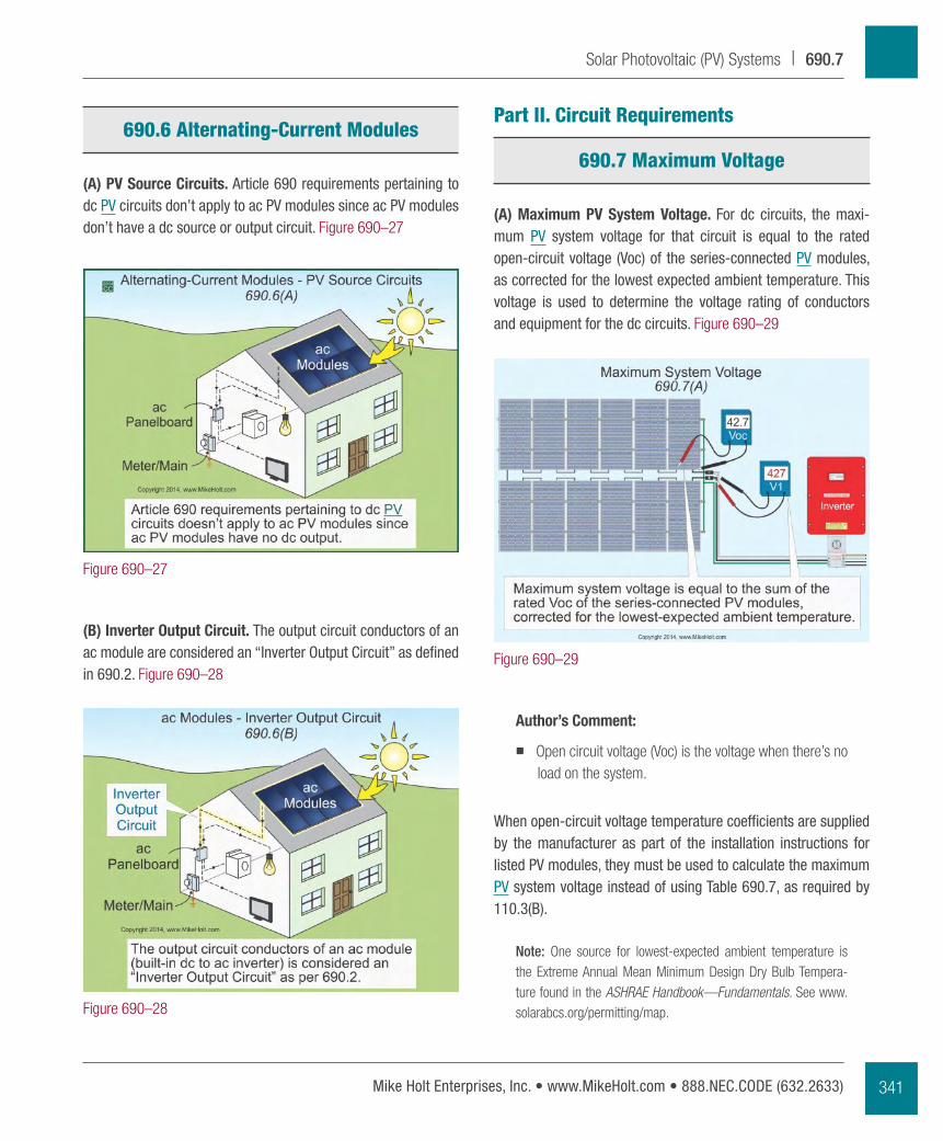
(A) Maximum PV System Voltage. For dc circuits, the maxi-mum pV system voltage for that circuit is equal to the rated open-circuit voltage (Voc) of the series-connected pV modules, as corrected for the lowest expected ambient temperature. This voltage is used to determine the voltage rating of conductors and equipment for the dc circuits. Figure 690–29
Author’s Comment:
� Open circuit voltage (Voc) is the voltage when there’s no load on the system.
When open-circuit voltage temperature coefficients are supplied by the manufacturer as part of the installation instructions for listed pV modules, they must be used to calculate the maximum pV system voltage instead of using Table 690.7, as required by 110.3(B).
Note: One source for lowest-expected ambient temperature is the Extreme Annual Mean Minimum Design Dry Bulb Tempera-ture found in the ASHRAE Handbook—Fundamentals. See www.solarabcs.org/permitting/map.
690.6 Alternating-Current Modules
(A) PV Source Circuits. Article 690 requirements pertaining to dc pV circuits don’t apply to ac pV modules since ac pV modules don’t have a dc source or output circuit. Figure 690–27
(B) Inverter Output Circuit. The output circuit conductors of an ac module are considered an “Inverter Output Circuit” as defined in 690.2. Figure 690–28
Figure 690–27
Figure 690–28
Figure 690–29
341Mike Holt Enterprises, Inc. • www.MikeHolt.com • 888.NEC.CODE (632.2633)
Solar Photovoltaic (PV) Systems | 690.7
PV System Voltage Based on Manufacturer Temperature Coefficient V/ºC
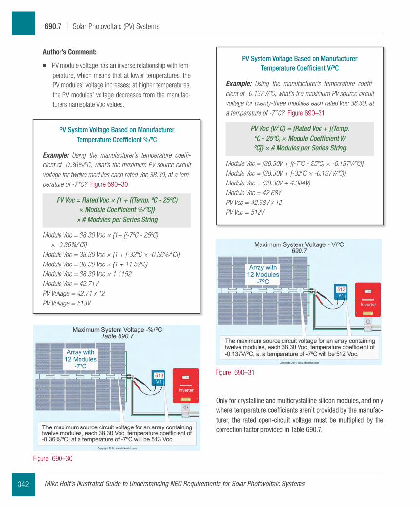
Example: Using the manufacturer’s temperature coeffi-cient of -0.137V/ºC, what’s the maximum PV source circuit voltage for twenty-three modules each rated Voc 38.30, at a temperature of -7°C? Figure 690–31
PV Voc (V/ºC) = {Rated Voc + [(Temp. ºC - 25ºC) × Module Coefficient V/ºC]} × # Modules per Series String
Module Voc = {38.30V + [(-7ºC - 25ºC) × -0.137V/ºC]}Module Voc = {38.30V + [-32ºC × -0.137V/ºC))Module Voc = (38.30V + 4.384V)Module Voc = 42.68VPV Voc = 42.68V x 12PV Voc = 512V
Only for crystalline and multicrystalline silicon modules, and only where temperature coefficients aren’t provided by the manufac-turer, the rated open-circuit voltage must be multiplied by the correction factor provided in Table 690.7.
Author’s Comment:
� PV module voltage has an inverse relationship with tem-perature, which means that at lower temperatures, the PV modules’ voltage increases; at higher temperatures, the PV modules’ voltage decreases from the manufac-turers nameplate Voc values.
PV System Voltage Based on Manufacturer Temperature Coefficient %/ºC
Example: Using the manufacturer’s temperature coeffi-cient of -0.36%/ºC, what’s the maximum PV source circuit voltage for twelve modules each rated Voc 38.30, at a tem-perature of -7°C? Figure 690–30
PV Voc = Rated Voc × {1 + [(Temp. ºC - 25ºC) × Module Coefficient %/ºC]}
× # Modules per Series String
Module Voc = 38.30 Voc × {1+ [(-7ºC - 25ºC) × -0.36%/ºC]}
Module Voc = 38.30 Voc × {1 + [-32ºC × -0.36%/ºC]}Module Voc = 38.30 Voc × {1 + 11.52%}Module Voc = 38.30 Voc × 1.1152Module Voc = 42.71VPV Voltage = 42.71 x 12PV Voltage = 513V
Figure 690–30
Figure 690–31
Mike Holt’s Illustrated Guide to Understanding NEC Requirements for Solar Photovoltaic Systems342
690.7 | Solar Photovoltaic (PV) Systems
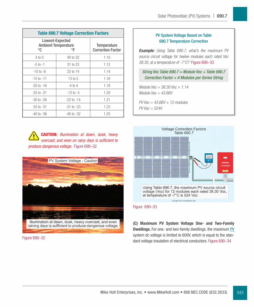
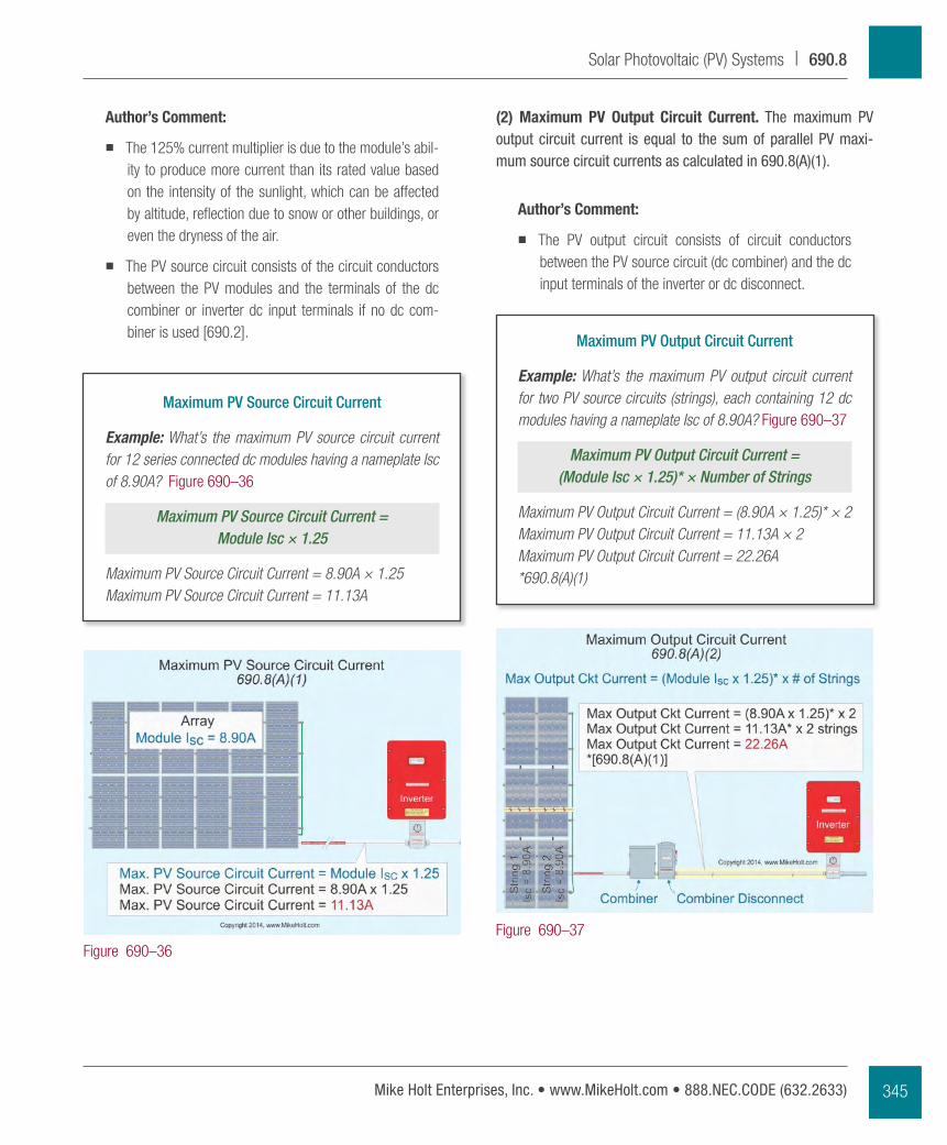
PV System Voltage Based on Table 690.7 Temperature Correction
Example: Using Table 690.7, what’s the maximum PV source circuit voltage for twelve modules each rated Voc 38.30, at a temperature of -7°C? Figure 690–33
String Voc Table 690.7 = Module Voc × Table 690.7 Correction Factor × # Modules per Series String
Module Voc = 38.30 Voc × 1.14Module Voc = 43.66V
PV Voc = 43.66V × 12 modulesPV Voc = 524V
(C) Maximum PV System Voltage One- and Two-Family Dwellings. For one- and two-family dwellings, the maximum pV system dc voltage is limited to 600V, which is equal to the stan-dard voltage insulation of electrical conductors. Figure 690–34
Table 690.7 Voltage Correction Factors
Lowest-Expected Ambient Temperature °C °F
Temperature Correction Factor
4 to 0 40 to 32 1.10
-5 to -1 31 to 23 1.12
-10 to -6 22 to 14 1.14
-15 to -11 13 to 5 1.16
-20 to -16 -4 to 4 1.18
-25 to -21 -13 to -5 1.20
-30 to -26 -22 to -14 1.21
-35 to -31 -31 to -23 1.23
-40 to -36 -40 to -32 1.25
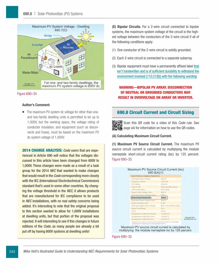
CAUTION: Illumination at dawn, dusk, heavy overcast, and even on rainy days is sufficient to
produce dangerous voltage. Figure 690–32
Figure 690–32
Figure 690–33
343Mike Holt Enterprises, Inc. • www.MikeHolt.com • 888.NEC.CODE (632.2633)
Solar Photovoltaic (PV) Systems | 690.7
(E) Bipolar Circuits. For a 2-wire circuit connected to bipolar systems, the maximum system voltage of the circuit is the high-est voltage between the conductors of the 2-wire circuit if all of the following conditions apply:
(1) One conductor of the 2-wire circuit is solidly grounded.
(2) Each 2-wire circuit is connected to a separate subarray.
(3) Bipolar equipment must have a permanently affixed label that isn’t handwritten and is of sufficient durability to withstand the environment involved [110.21(B)] with the following wording:
WARNING—BIPOLAR PV ARRAY. DISCONNECTION OF NEUTRAL OR GROUNDED CONDUCTORS MAY
RESULT IN OVERVOLTAGE ON ARRAY OR INVERTER.
690.8 Circuit Current and Circuit Sizing
Scan this qR code for a video of this Code rule. See page xiii for information on how to use the qR codes.
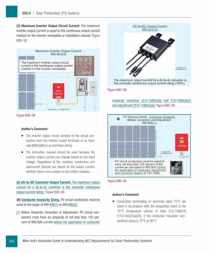
(A) Calculating Maximum Circuit Current.
(1) Maximum PV Source Circuit Current. The maximum pV source circuit current is calculated by multiplying the module nameplate short-circuit current rating (Isc) by 125 percent. Figure 690–35
Author’s Comment:
� The maximum PV system dc voltage for other than one- and two-family dwelling units is permitted to be up to 1,000V, but the working space, the voltage rating of conductor insulation, and equipment (such as discon-nects and fuses), must be based on the maximum PV dc system voltage of 1,000V.
2014 CHANGE ANALYSIS: Code users that are expe-rienced in Article 690 will notice that the voltages dis-cussed in this article have been changed from 600V to 1,000V. These changes were made as a result of a task group for the 2014 NEC that wanted to make changes that would result in the Code corresponding more closely with the IEC (International Electrotechnical Commission) standard that’s used in some other countries. By chang-ing the voltage threshold in the NEC, it allows products that are manufactured for IEC compliance to be used in NEC installations, with no real safety concerns being added. It’s interesting to note that the original proposal to this section wanted to allow for 1,000V installations at dwelling units, but that portion of the proposal was rejected. It will interesting to see if this changes in future editions of the Code, as many people are already a bit put off by having 600V systems at dwelling units!
Figure 690–34
Figure 690–35
Mike Holt’s Illustrated Guide to Understanding NEC Requirements for Solar Photovoltaic Systems344
690.8 | Solar Photovoltaic (PV) Systems
(2) Maximum PV Output Circuit Current. The maximum pV output circuit current is equal to the sum of parallel pV maxi-mum source circuit currents as calculated in 690.8(A)(1).
Author’s Comment:
� The PV output circuit consists of circuit conductors between the PV source circuit (dc combiner) and the dc input terminals of the inverter or dc disconnect.
Maximum PV Output Circuit Current
Example: What’s the maximum PV output circuit current for two PV source circuits (strings), each containing 12 dc modules having a nameplate Isc of 8.90A? Figure 690–37
Maximum PV Output Circuit Current = (Module Isc × 1.25)* × Number of Strings
Maximum PV Output Circuit Current = (8.90A × 1.25)* × 2Maximum PV Output Circuit Current = 11.13A × 2Maximum PV Output Circuit Current = 22.26A*690.8(A)(1)
Author’s Comment:
� The 125% current multiplier is due to the module’s abil-ity to produce more current than its rated value based on the intensity of the sunlight, which can be affected by altitude, reflection due to snow or other buildings, or even the dryness of the air.
� The PV source circuit consists of the circuit conductors between the PV modules and the terminals of the dc combiner or inverter dc input terminals if no dc com-biner is used [690.2].
Maximum PV Source Circuit Current
Example: What’s the maximum PV source circuit current for 12 series connected dc modules having a nameplate Isc of 8.90A? Figure 690–36
Maximum PV Source Circuit Current = Module Isc × 1.25
Maximum PV Source Circuit Current = 8.90A × 1.25Maximum PV Source Circuit Current = 11.13A
Figure 690–36Figure 690–37
345Mike Holt Enterprises, Inc. • www.MikeHolt.com • 888.NEC.CODE (632.2633)
Solar Photovoltaic (PV) Systems | 690.8
ampacity correction [310.15(B)(2)(a) and 310.15(B)(3)(c)] and adjustment [310.15(B)(3)(a)]. Figure 690–40
Author’s Comment:
� Conductors terminating on terminals rated 75°C are sized in accordance with the ampacities listed in the 75°C temperature column of Table 310.15(B)(16) [110.14(C)(1)(a)(3)], if the conductor insulation tem-perature rating is 75°C or 90°C.
(3) Maximum Inverter Output Circuit Current. The maximum inverter output current is equal to the continuous output current marked on the inverter nameplate or installation manual. Figure 690–38
Author’s Comment:
� The inverter output circuit consists of the circuit con-ductors from the inverter output terminals or ac mod-ules [690.6(B)] to ac premises wiring.
� The instruction manual should be used because the inverter output current can change based on the input voltage. Regardless of the modules, conductors and overcurrent devices are based on the output current, whether there’s one module or one million modules.
(5) DC-to-DC Converter Output Current. The maximum output current for a dc-to-dc converter is the converter continuous output current rating. Figure 690–39
(B) Conductor Ampacity Sizing. pV circuit conductors must be sized to the larger of 690.8(B)(1) or 690.8(B)(2).
(1) Before Ampacity Correction or Adjustment. pV circuit con-ductors must have an ampacity of not less than 125 per-cent of 690.8(A) current before the application of conductor
Figure 690–38
Figure 690–39
Figure 690–40
Mike Holt’s Illustrated Guide to Understanding NEC Requirements for Solar Photovoltaic Systems346
690.8 | Solar Photovoltaic (PV) Systems
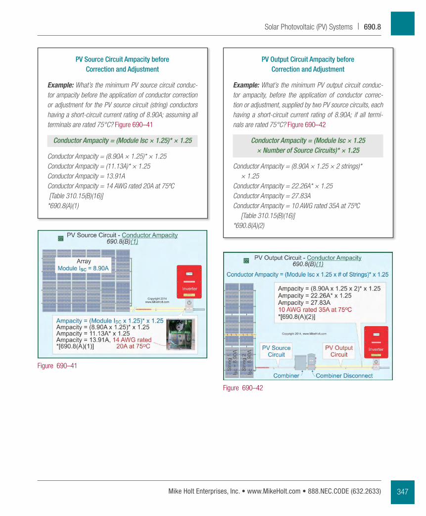
PV Output Circuit Ampacity before Correction and Adjustment
Example: What’s the minimum PV output circuit conduc-tor ampacity, before the application of conductor correc-tion or adjustment, supplied by two PV source circuits, each having a short-circuit current rating of 8.90A; if all termi-nals are rated 75°C? Figure 690–42
Conductor Ampacity = (Module Isc × 1.25 × Number of Source Circuits)* × 1.25
Conductor Ampacity = (8.90A × 1.25 × 2 strings)* × 1.25
Conductor Ampacity = 22.26A* × 1.25Conductor Ampacity = 27.83AConductor Ampacity = 10 AWG rated 35A at 75ºC
[Table 310.15(B)(16)]*690.8(A)(2)
PV Source Circuit Ampacity before Correction and Adjustment
Example: What’s the minimum PV source circuit conduc-tor ampacity before the application of conductor correction or adjustment for the PV source circuit (string) conductors having a short-circuit current rating of 8.90A; assuming all terminals are rated 75°C? Figure 690–41
Conductor Ampacity = (Module Isc × 1.25)* × 1.25
Conductor Ampacity = (8.90A × 1.25)* × 1.25Conductor Ampacity = (11.13A)* × 1.25Conductor Ampacity = 13.91AConductor Ampacity = 14 AWG rated 20A at 75ºC [Table 310.15(B)(16)]*690.8(A)(1)
Figure 690–41
Figure 690–42
347Mike Holt Enterprises, Inc. • www.MikeHolt.com • 888.NEC.CODE (632.2633)
Solar Photovoltaic (PV) Systems | 690.8
Author’s Comment:
� When performing conductor ampacity correction and adjustment calculations, use the conductor ampac-ity listed in the 90°C column of Table 310.15(B)(16) for RHH/RHW-2/USE-2 [310.15(B)] and PV wire at 90°C [110.14(C)(1)(b)(2)]. Figure 690–45
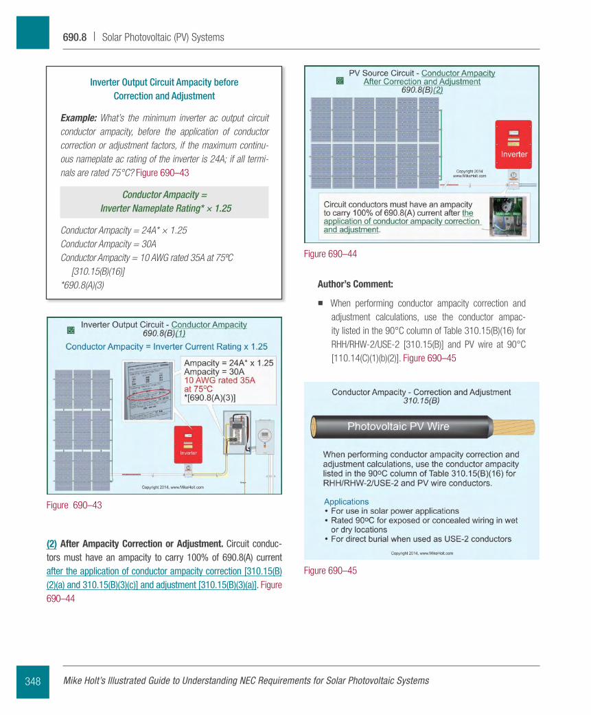
Inverter Output Circuit Ampacity before Correction and Adjustment
Example: What’s the minimum inverter ac output circuit conductor ampacity, before the application of conductor correction or adjustment factors, if the maximum continu-ous nameplate ac rating of the inverter is 24A; if all termi-nals are rated 75°C? Figure 690–43
Conductor Ampacity = Inverter Nameplate Rating* × 1.25
Conductor Ampacity = 24A* × 1.25Conductor Ampacity = 30AConductor Ampacity = 10 AWG rated 35A at 75ºC
[310.15(B)(16)]*690.8(A)(3)
(2) After Ampacity Correction or Adjustment. Circuit conduc-tors must have an ampacity to carry 100% of 690.8(A) current after the application of conductor ampacity correction [310.15(B)(2)(a) and 310.15(B)(3)(c)] and adjustment [310.15(B)(3)(a)]. Figure 690–44
Figure 690–44
Figure 690–45
Figure 690–43
Mike Holt’s Illustrated Guide to Understanding NEC Requirements for Solar Photovoltaic Systems348
690.8 | Solar Photovoltaic (PV) Systems
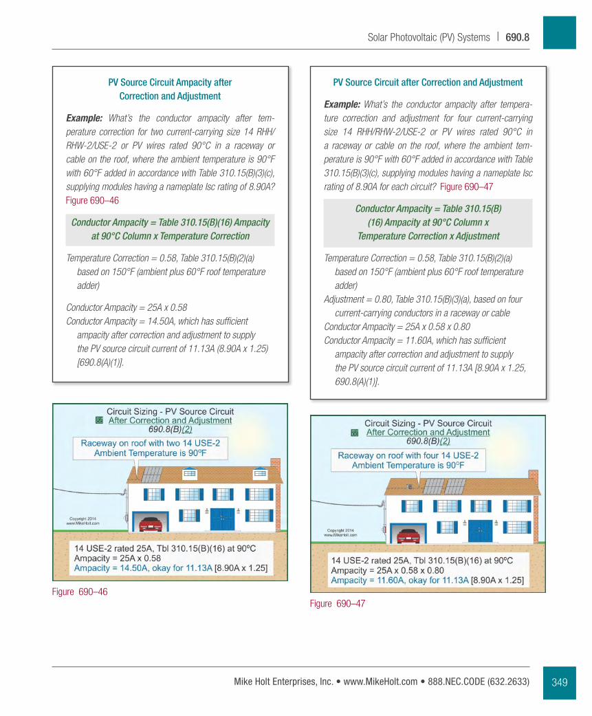
PV Source Circuit after Correction and Adjustment
Example: What’s the conductor ampacity after tempera-ture correction and adjustment for four current-carrying size 14 RHH/RHW-2/USE-2 or PV wires rated 90°C in a raceway or cable on the roof, where the ambient tem-perature is 90°F with 60°F added in accordance with Table 310.15(B)(3)(c), supplying modules having a nameplate Isc rating of 8.90A for each circuit? Figure 690–47
Conductor Ampacity = Table 310.15(B)(16) Ampacity at 90°C Column x
Temperature Correction x Adjustment
Temperature Correction = 0.58, Table 310.15(B)(2)(a) based on 150°F (ambient plus 60°F roof temperature adder)
Adjustment = 0.80, Table 310.15(B)(3)(a), based on four current-carrying conductors in a raceway or cable
Conductor Ampacity = 25A x 0.58 x 0.80Conductor Ampacity = 11.60A, which has sufficient
ampacity after correction and adjustment to supply the PV source circuit current of 11.13A [8.90A x 1.25, 690.8(A)(1)].
PV Source Circuit Ampacity after Correction and Adjustment
Example: What’s the conductor ampacity after tem-perature correction for two current-carrying size 14 RHH/RHW-2/USE-2 or PV wires rated 90°C in a raceway or cable on the roof, where the ambient temperature is 90°F with 60°F added in accordance with Table 310.15(B)(3)(c), supplying modules having a nameplate Isc rating of 8.90A? Figure 690–46
Conductor Ampacity = Table 310.15(B)(16) Ampacity at 90°C Column x Temperature Correction
Temperature Correction = 0.58, Table 310.15(B)(2)(a) based on 150°F (ambient plus 60°F roof temperature adder)
Conductor Ampacity = 25A x 0.58Conductor Ampacity = 14.50A, which has sufficient
ampacity after correction and adjustment to supply the PV source circuit current of 11.13A (8.90A x 1.25) [690.8(A)(1)].
Figure 690–46Figure 690–47
349Mike Holt Enterprises, Inc. • www.MikeHolt.com • 888.NEC.CODE (632.2633)
Solar Photovoltaic (PV) Systems | 690.8
Overcurrent devices for pV source circuits (strings) and pV output circuits must comply with (A) through (E). Circuits that are con-nected to both a power limited supply (such as a pV module) and another supply that has high available fault current (such as an utility) must be protected against overcurrent from both systems.
Author’s Comment:
� For an ungrounded system [690.35], both the positive and negative conductor must have overcurrent protec-tion; for grounded systems, only the ungrounded con-ductor requires overcurrent protection [240.15].
Ex: Overcurrent protection isn’t required for PV dc circuits where:
(a) There are no external sources such as parallel-connected source circuits, batteries, or backfeed from inverters.
(b) The short-circuit currents (Isc) from all sources don’t exceed the ampacity of the PV circuit conductors or the maximum overcurrent device size specified on the PV module name-plate. Figure 690–50
Author’s Comment:
� This occurs when the PV source or PV output circuits consist of no more than two circuits and the inverter isn’t capable of being backfed to the PV array. When
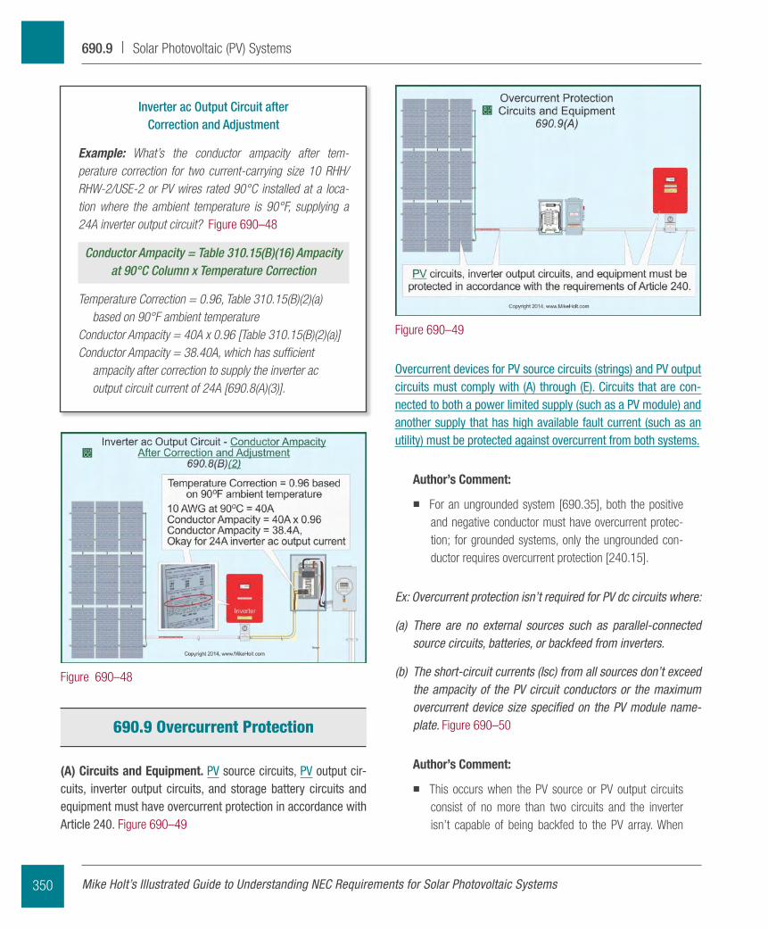
Inverter ac Output Circuit after Correction and Adjustment
Example: What’s the conductor ampacity after tem-perature correction for two current-carrying size 10 RHH/RHW-2/USE-2 or PV wires rated 90°C installed at a loca-tion where the ambient temperature is 90°F, supplying a 24A inverter output circuit? Figure 690–48
Conductor Ampacity = Table 310.15(B)(16) Ampacity at 90°C Column x Temperature Correction
Temperature Correction = 0.96, Table 310.15(B)(2)(a) based on 90°F ambient temperature
Conductor Ampacity = 40A x 0.96 [Table 310.15(B)(2)(a)]Conductor Ampacity = 38.40A, which has sufficient
ampacity after correction to supply the inverter ac output circuit current of 24A [690.8(A)(3)].
690.9 Overcurrent Protection
(A) Circuits and Equipment. pV source circuits, pV output cir-cuits, inverter output circuits, and storage battery circuits and equipment must have overcurrent protection in accordance with Article 240. Figure 690–49
Figure 690–49
Figure 690–48
Mike Holt’s Illustrated Guide to Understanding NEC Requirements for Solar Photovoltaic Systems350
690.9 | Solar Photovoltaic (PV) Systems