Solar or AC Charged - Gate Depot Inc
76
USAutomatic PATRIOT High Quality Low Voltage Vehicular Swing Gate Operator Solar or AC Charged PATRIOT I Single Swing Gate Operator PATRIOT II Dual Swing Gate Operator Installation/Owners Manual PROUDLY MADE IN THE USA www.usautomatic.com
Transcript of Solar or AC Charged - Gate Depot Inc
USAutomatic
PATRIOT High Quality Low Voltage
Vehicular Swing Gate Operator Solar or AC Charged
PATRIOT I Single Swing Gate Operator
PATRIOT II Dual Swing Gate Operator
Installation/Owners Manual
PROUDLY MADE IN THE USA www.usautomatic.com

36
1
INTRODUCTION
This operator is intended to be installed on vehicular Class I or Class II gates as defined by UL-325. Maximum gate load should not exceed 650 pounds.
PLEASE READ THIS ENTIRE MANUAL CAREFULLY PRIOR TO INSTALLATION.
Perform the installation in step-by-step order you will achieve optimal results. We strongly recommend that all installation and service personnel pay particularly close attention to the safety systems section of this manual and UL-325. In addition to the current sense feature that is provided, other safety devices are necessary to make each particular installation as safe as possible to reduce the risk of personal injury and/or property damage. A trained and authorized service technician or the factory should be consulted for assistance.
Cautions - Very Important
Do not attempt to enter the gate area while the gate is moving. Wait until the gate comes to a complete stop.
Operate the gate only when it is fully visible, free of persons or obstructions, and properly adjusted.
Do not allow children to play in the area of the gate. Do not allow anyone to ride on the gate.
Do not allow children to play with the remote/transmitter or any other activation device.
Do not attempt to "beat the gate" while the gate is opening or closing. This is extremely dangerous.
Test the current sense feature and all safety devices regularly to insure correct operation.
Study the entire Safety Section (page 22-25), paying particularly close attention to the Entrapment zones on page 23-25 and be aware of these areas not only during use but also during any adjustments to the unit.
The USAutomatic battery charger is designed to operate with +12 vdc battery rated at 33-amp hour minimum. Maintenance free lead acid, Gel type or AGM batteries are recommended.
Modifying the charger AC supply cord will void the charger warranty.
Other Safety Standards
All control stations should be located at least 6 feet from any moving part of the gate or operator.
Never install any control device where a user will be tempted to reach through the gate or fence to activate a gate.
© USAutomatic, LTD - 2007 rev ZL
All rights reserved. No part of this may be reproduced by any means without the expressed written consent of the publisher.

2
Table Of Contents Page
Introduction ............................................................................................. 1 Table of Contents .................................................................................... 2 General Requirements/Gate Qualifications & Applications ................... 3 Importance of a Properly Designed Gate ................................................ 4 Mounting Site Review ............................................................................. 4 Parts Included List ................................................................................... 5 Hinge Mount Tube Installation/Pull to Open .......................................... 6 Hinge Mount Tube Installation/Push to Open/Vertical Height .............. 7 Gate Bracket Installation/Pull to Open ................................................... 8 Gate Bracket Installation/Push to Open/Diagrams ................................. 9 Mounting the Control Box/Splicing Actuator Cable ............................. 10 Installation of Charging Device ............................................................. 11 Connecting Actuator Cable and Charging Device to battery ................. 11 Connecting Actuator Cable to Control Board. ....................................... 12 Current Sense Adjustment ...................................................................... 12 Control Board Dipswitch Setting Verification ....................................... 13 Operating the Gate ................................................................................. 13 Making Final Adjustments ..................................................................... 14 Installing Safety Placards/Installing Secondary Entrapment Siren ........ 14 Limit Switch Adjustment ....................................................................... 15 Control Board Terminal Description For Accessories ........................... 16 Function of Programming Switch Settings DS1 .................................... 17 Function of Programming Switch Settings DS2 .................................... 18 Emergency Manual Release ................................................................... 18 Programming Remote/Transmitter and Receiver............................. 19-21 Safety Section ................................................................................... 22-25 Periodic Service ...................................................................................... 26 Troubleshooting Guide ..................................................................... 26-33 Accessory Wiring Information ......................................................... 34-36 Solar Friendly Photo Eye Wiring Diagram ............................................ 36 Warranty Statement .................................................................. Back Cover
3
GENERAL REQUIREMENTS
General hand/tools such as combination wrenches, tape measure, level, clamps, etc. are required. Your particular installation may require a drill or other hardware not provided. Welding by a qualified welder is the recommended method of securing the linear actuator mounts to the gate and hinge post. Bolt on brackets is an option, but they must be very securely attached (i.e. carriage bolts with lock nuts and washers). Lag type bolts are not recommended. Loose or unstable operator mounts will result in improper operation.
BATTERY REQUIRED FOR OPERATION (NOT INCLUDED).
We recommend a +12 vdc maintenance free lead acid, Gel or AGM battery rated at a minimum of 33-amp hours. The actuator harness is equipped with 3/8” ring terminals designed to connect to bolt type battery posts. The USAutomatic charger is designed for this type of battery. Using a smaller amp hour battery may cause damage to the charging system.
IMPORTANT CAUTIONS:
1. Do not test or operate this unit without the actuator securely attached to the gate. Serious damage to the actuator limit switch assembly may occur if attempted.
2. Do not perform any welding while the actuator cable is plugged into the control board or with the battery connected. Serious damage to the control board and/or battery will occur if attempted.
3. Always disconnect the battery power from the unit prior to connecting any devices.
GATE QUALIFICATIONS/APPLICATIONS
GATE LENGTH/WEIGHT This gate operator is rated for vehicular class I or class II swing gates up to 16 feet in length and up to 650 pounds in weight, as defined by UL-325. If your gate exceeds either one of these limits, please consult a qualified technician or the factory for alternative solutions. (Example: Convert one 20' gate into two 10' gates and use a dual gate operator.)
Note: The total gate opening normally cannot exceed 120 degrees. Consult a service technician or the factory if greater opening is required.
GATE CYCLES PER DAY
Solar charged systems have a limit on the number of cycles they can provide on a daily basis. System design must consider stand-by current consumption of all accessories and number of cycles expected per day. A solar operator will not need additional solar panels in most installations if solar friendly accessories are used. Contact the factory for help designing a solar friendly system. This actuator type opener, whether AC or Solar charged, should never be used in applications that require 150 or more complete open/close cycles per day. Holding the gate open can decrease cycles during high cycle time periods. A high traffic gate operator should be used if more cycles are required.

4
IMPORTANCE OF A PROPERLY DESIGNED GATE
As a general rule, an automatically operated gate must be stronger and smoother than a manually operated gate. Since the gate is a major component of the system, great care and concern must be given to the gate design.
A GATE OPERATOR CANNOT OVERCOME A POORLY DESIGNED GATE.
A. Does the gate swing smoothly without binds or excessive resistance? Swing gates should swing level and plumb to prevent the operator from having to lift the gate open or closed. Swing gates should not require a wheel to support them. Wheels usually create drag, which will cause operator problems. A wheel is generally a sign of a weak hinge system or a weak gate frame.
B. Is the gate frame of substantial strength without excessive weight? Will the frame withstand normal wind load conditions without sway or vibration? Will the gate close correctly without being hand-guided or lifted to close?
C. Are the hinges suited for the number of cycles expected per day? We recommend bearing type hinges to reduce friction drag. D. Will a reinforcement brace be required to attach the operator to the gate or does a suitable cross member exist in the gate design?
If any of these problems exist, they must be corrected to achieve a reliable automatic gate system.
MOUNTING SITE REVIEW
Installers should ask themselves these questions prior to installation and predetermine the solution to any problems which may occur. A. Does sufficient space exist for mounting and future servicing of the operator and
control box? B. Will the unit push the gate open to the outside or pull the gate open to the inside? C. How will the actuator mounts be secured at the hinge and to the gate? D. How will the control box be mounted so it is secure enough to support the weight of
the battery and be located within 8 feet of the actuator arm to prevent splicing of the actuator cable?
E. How will power be brought to the control box if AC charged? E. How and where will the solar panel be mounted, if solar charged, so that optimum
sunlight is received? G. How will exterior control wiring, if any, be brought to the control box? H. Have all safety concerns been addressed? (See Safety Section Pgs. 22-25)
5
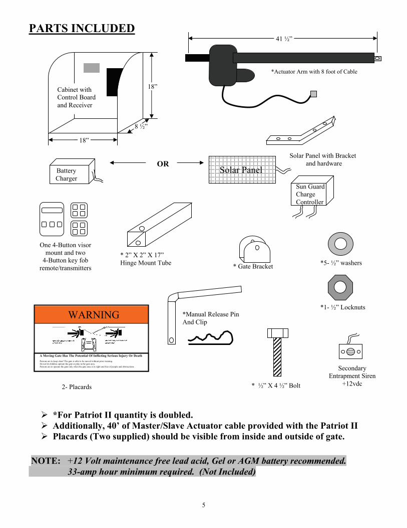
PARTS INCLUDED
OR
*For Patriot II quantity is doubled. Additionally, 40’ of Master/Slave Actuator cable provided with the Patriot II Placards (Two supplied) should be visible from inside and outside of gate.
NOTE: +12 Volt maintenance free lead acid, Gel or AGM battery recommended. 33-amp hour minimum required. (Not Included)
* 2” X 2” X 17” Hinge Mount Tube
Solar Panel with Bracketand hardware
*5- ½” washers
*1- ½” Locknuts
2- Placards * ½” X 4 ½” Bolt
*Manual Release PinAnd Clip
* Gate Bracket
WARNING
A Moving Gate Has The Potential Of Inflicting Serious Injury Or Death Persons are to keep clear! The gate is able to be moved without prior warning. Do not let children operate the gate or play in the gate area. Persons are to operate the gate only when the gate area is in sight and free of people and obstructions.
Battery Charger
Solar Panel
One 4-Button visor mount and two
4-Button key fob remote/transmitters
41 ½”
Cabinet with Control Board and Receiver
18”
8 ½”
18”
*Actuator Arm with 8 foot of Cable
Secondary Entrapment Siren
+12vdc
Sun Guard Charge Controller
6
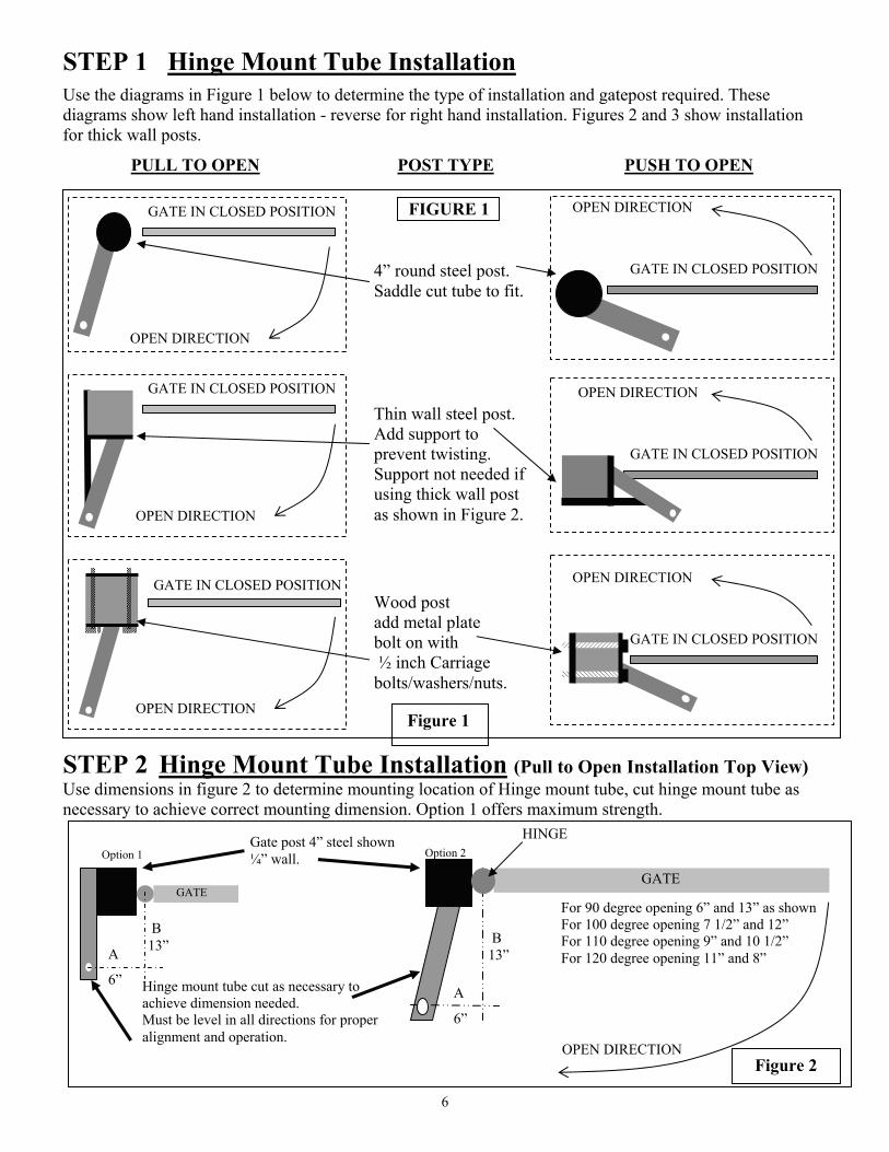
STEP 1 Hinge Mount Tube Installation
Use the diagrams in Figure 1 below to determine the type of installation and gatepost required. These diagrams show left hand installation - reverse for right hand installation. Figures 2 and 3 show installation for thick wall posts.
PULL TO OPEN POST TYPE PUSH TO OPEN
STEP 2 Hinge Mount Tube Installation (Pull to Open Installation Top View) Use dimensions in figure 2 to determine mounting location of Hinge mount tube, cut hinge mount tube as necessary to achieve correct mounting dimension. Option 1 offers maximum strength.
GATE IN CLOSED POSITION
Thin wall steel post. Add support to prevent twisting. Support not needed if using thick wall post as shown in Figure 2.
GATE IN CLOSED POSITION
4” round steel post. Saddle cut tube to fit.
Wood post add metal plate bolt on with ½ inch Carriage bolts/washers/nuts.
GATE IN CLOSED POSITION
OPEN DIRECTION
OPEN DIRECTION
OPEN DIRECTION
OPEN DIRECTION
GATE IN CLOSED POSITION
GATE IN CLOSED POSITION
GATE IN CLOSED POSITION
OPEN DIRECTION
OPEN DIRECTION
FIGURE 1
Hinge mount tube cut as necessary to achieve dimension needed. Must be level in all directions for proper alignment and operation.
Figure 2
B 13” A
6”
Option 1
GATE
Option 2 Gate post 4” steel shown ¼” wall.
B 13”
A
6”
For 90 degree opening 6” and 13” as shown For 100 degree opening 7 1/2” and 12” For 110 degree opening 9” and 10 1/2” For 120 degree opening 11” and 8”
GATE
OPEN DIRECTION
HINGE
Figure 1
7
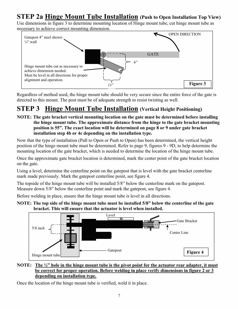
STEP 2a Hinge Mount Tube Installation (Push to Open Installation Top View) Use dimensions in figure 3 to determine mounting location of Hinge mount tube, cut hinge mount tube as necessary to achieve correct mounting dimension.
Regardless of method used, the hinge mount tube should be very secure since the entire force of the gate is directed to this mount. The post must be of adequate strength to resist twisting as well.
STEP 3 Hinge Mount Tube Installation (Vertical Height Positioning)
NOTE: The gate bracket vertical mounting location on the gate must be determined before installing the hinge mount tube. The approximate distance from the hinge to the gate bracket mounting position is 55”. The exact location will be determined on page 8 or 9 under gate bracket installation step 4b or 4c depending on the installation type.
Now that the type of installation (Pull to Open or Push to Open) has been determined, the vertical height position of the hinge mount tube must be determined. Refer to page 9, figures 9 - 9D, to help determine the mounting location of the gate bracket, which is needed to determine the location of the hinge mount tube.
Once the approximate gate bracket location is determined, mark the center point of the gate bracket location on the gate.
Using a level, determine the centerline point on the gatepost that is level with the gate bracket centerline mark made previously. Mark the gatepost centerline point, see figure 4.
The topside of the hinge mount tube will be installed 5/8” below the centerline mark on the gatepost. Measure down 5/8” below the centerline point and mark the gatepost, see figure 4.
Before welding in place, ensure that the hinge mount tube is level in all directions.
NOTE: The top side of the hinge mount tube must be installed 5/8” below the centerline of the gate bracket. This will ensure that the actuator is level when installed.
NOTE: The ½” hole in the hinge mount tube is the pivot point for the actuator rear adapter, it must be correct for proper operation. Before welding in place verify dimensions in figure 2 or 3 depending on installation type.
Once the location of the hinge mount tube is verified, weld it in place.
Level
Figure 3
Gatepost
Gate Bracket
5/8 inch Center Line Hinge mount tube
Figure 4
OPEN DIRECTION
GATE
6”
11”
Gatepost 4” steel shown ¼” wall
Hinge mount tube cut as necessary to achieve dimension needed. Must be level in all directions for proper alignment and operation.
8
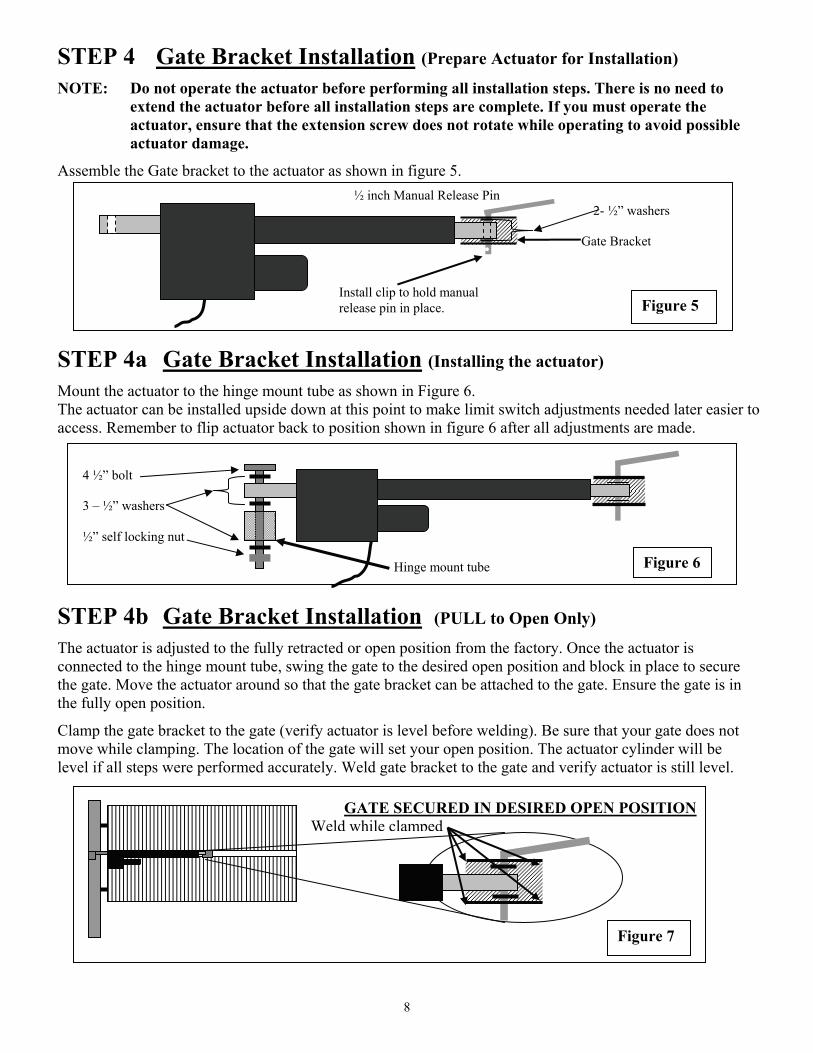
STEP 4 Gate Bracket Installation (Prepare Actuator for Installation)
NOTE: Do not operate the actuator before performing all installation steps. There is no need to extend the actuator before all installation steps are complete. If you must operate the actuator, ensure that the extension screw does not rotate while operating to avoid possible actuator damage.
Assemble the Gate bracket to the actuator as shown in figure 5. STEP 4a Gate Bracket Installation (Installing the actuator)
Mount the actuator to the hinge mount tube as shown in Figure 6. The actuator can be installed upside down at this point to make limit switch adjustments needed later easier to access. Remember to flip actuator back to position shown in figure 6 after all adjustments are made.
STEP 4b Gate Bracket Installation (PULL to Open Only)
The actuator is adjusted to the fully retracted or open position from the factory. Once the actuator is connected to the hinge mount tube, swing the gate to the desired open position and block in place to secure the gate. Move the actuator around so that the gate bracket can be attached to the gate. Ensure the gate is in the fully open position.
Clamp the gate bracket to the gate (verify actuator is level before welding). Be sure that your gate does not move while clamping. The location of the gate will set your open position. The actuator cylinder will be level if all steps were performed accurately. Weld gate bracket to the gate and verify actuator is still level.
4 ½” bolt 3 – ½” washers ½” self locking nut
Figure 6 Hinge mount tube
½ inch Manual Release Pin 2- ½” washers Gate Bracket
Figure 5 Install clip to hold manual release pin in place.
GATE SECURED IN DESIRED OPEN POSITION Weld while clamped
Figure 7
9
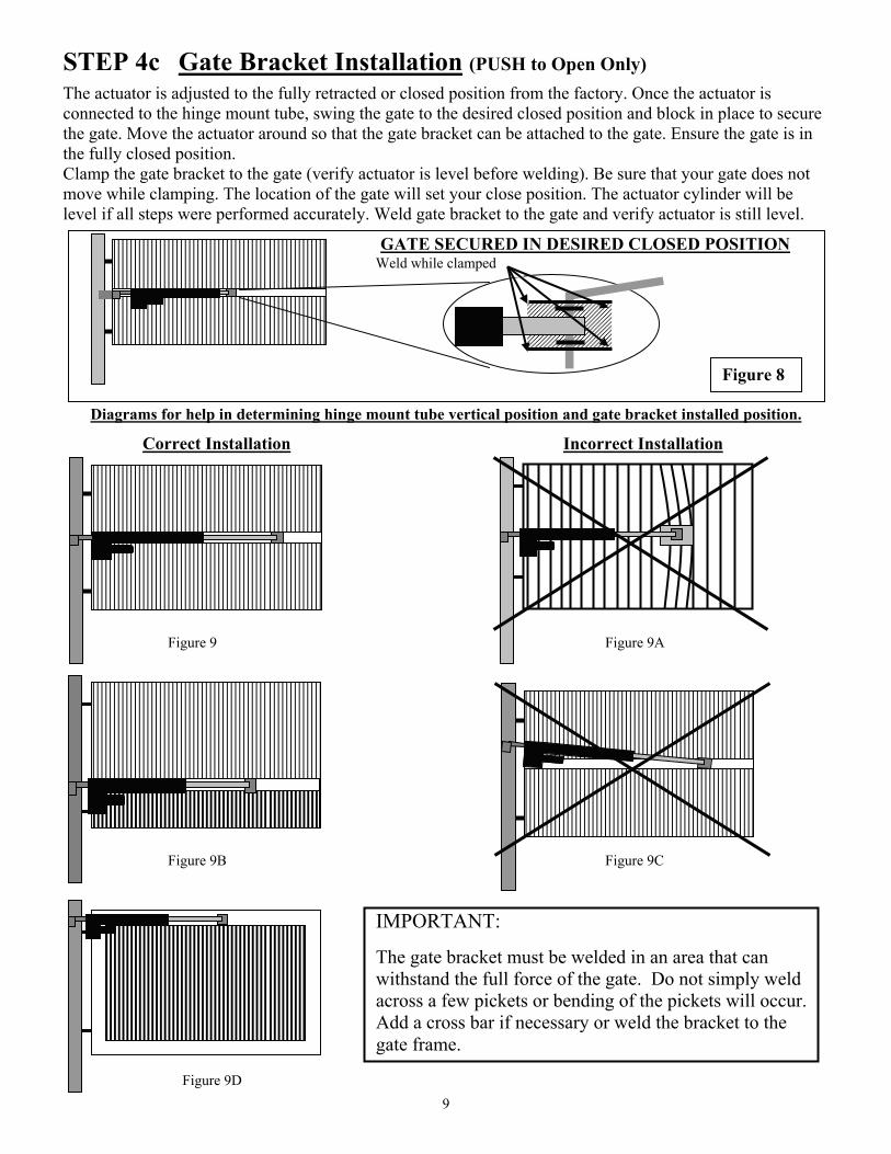
STEP 4c Gate Bracket Installation (PUSH to Open Only)
The actuator is adjusted to the fully retracted or closed position from the factory. Once the actuator is connected to the hinge mount tube, swing the gate to the desired closed position and block in place to secure the gate. Move the actuator around so that the gate bracket can be attached to the gate. Ensure the gate is in the fully closed position. Clamp the gate bracket to the gate (verify actuator is level before welding). Be sure that your gate does not move while clamping. The location of the gate will set your close position. The actuator cylinder will be level if all steps were performed accurately. Weld gate bracket to the gate and verify actuator is still level.
Diagrams for help in determining hinge mount tube vertical position and gate bracket installed position.
Correct Installation Incorrect Installation Figure 9 Figure 9A Figure 9B Figure 9C
IMPORTANT:
The gate bracket must be welded in an area that can withstand the full force of the gate. Do not simply weld across a few pickets or bending of the pickets will occur. Add a cross bar if necessary or weld the bracket to the gate frame.
GATE SECURED IN DESIRED CLOSED POSITION
Figure 8
Weld while clamped
Figure 9D
10
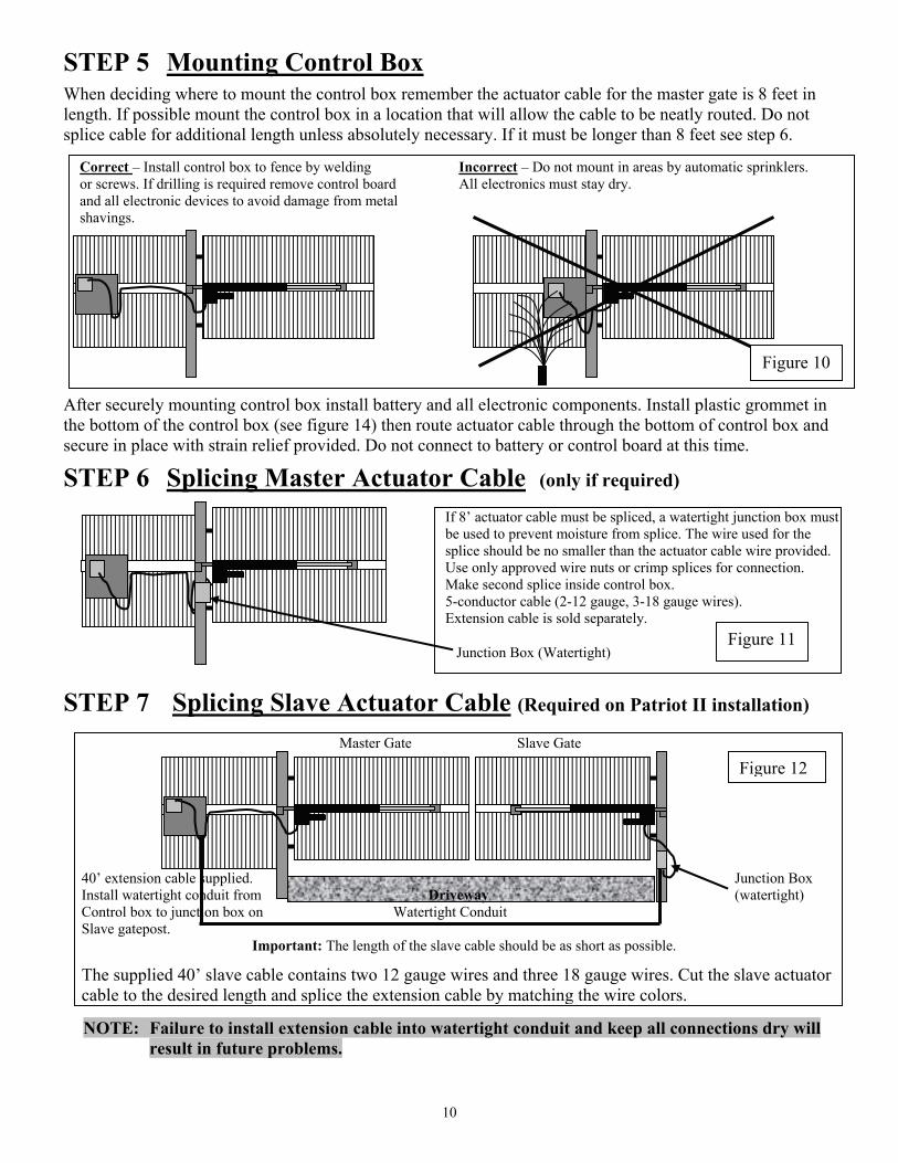
STEP 5 Mounting Control Box
When deciding where to mount the control box remember the actuator cable for the master gate is 8 feet in length. If possible mount the control box in a location that will allow the cable to be neatly routed. Do not splice cable for additional length unless absolutely necessary. If it must be longer than 8 feet see step 6.
After securely mounting control box install battery and all electronic components. Install plastic grommet in the bottom of the control box (see figure 14) then route actuator cable through the bottom of control box and secure in place with strain relief provided. Do not connect to battery or control board at this time.
STEP 6 Splicing Master Actuator Cable (only if required)
STEP 7 Splicing Slave Actuator Cable (Required on Patriot II installation)
NOTE: Failure to install extension cable into watertight conduit and keep all connections dry will result in future problems.
If 8’ actuator cable must be spliced, a watertight junction box must be used to prevent moisture from splice. The wire used for the splice should be no smaller than the actuator cable wire provided. Use only approved wire nuts or crimp splices for connection. Make second splice inside control box. 5-conductor cable (2-12 gauge, 3-18 gauge wires). Extension cable is sold separately. Junction Box (Watertight)
Master Gate Slave Gate 40’ extension cable supplied. Junction Box Install watertight conduit from Driveway (watertight) Control box to junction box on Watertight Conduit Slave gatepost.
Important: The length of the slave cable should be as short as possible.
The supplied 40’ slave cable contains two 12 gauge wires and three 18 gauge wires. Cut the slave actuator cable to the desired length and splice the extension cable by matching the wire colors.
Figure 12
Figure 11
Correct – Install control box to fence by welding Incorrect – Do not mount in areas by automatic sprinklers. or screws. If drilling is required remove control board All electronics must stay dry. and all electronic devices to avoid damage from metal shavings. Figure 10
11
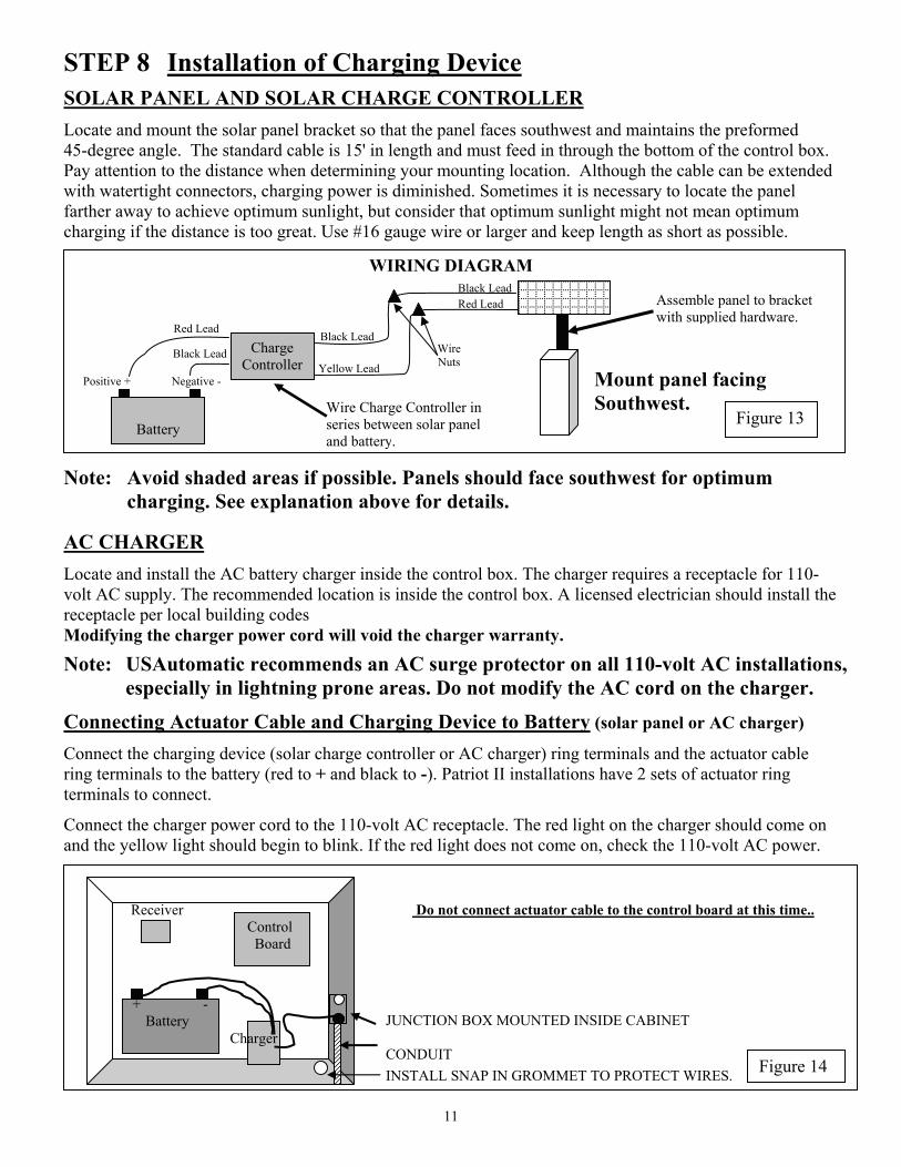
STEP 8 Installation of Charging Device
SOLAR PANEL AND SOLAR CHARGE CONTROLLER
Locate and mount the solar panel bracket so that the panel faces southwest and maintains the preformed 45-degree angle. The standard cable is 15' in length and must feed in through the bottom of the control box. Pay attention to the distance when determining your mounting location. Although the cable can be extended with watertight connectors, charging power is diminished. Sometimes it is necessary to locate the panel farther away to achieve optimum sunlight, but consider that optimum sunlight might not mean optimum charging if the distance is too great. Use #16 gauge wire or larger and keep length as short as possible.
WIRING DIAGRAM Mount panel facing
Southwest.
Note: Avoid shaded areas if possible. Panels should face southwest for optimum charging. See explanation above for details.
AC CHARGER
Locate and install the AC battery charger inside the control box. The charger requires a receptacle for 110-volt AC supply. The recommended location is inside the control box. A licensed electrician should install the receptacle per local building codes Modifying the charger power cord will void the charger warranty.
Note: USAutomatic recommends an AC surge protector on all 110-volt AC installations, especially in lightning prone areas. Do not modify the AC cord on the charger.
Connecting Actuator Cable and Charging Device to Battery (solar panel or AC charger)
Connect the charging device (solar charge controller or AC charger) ring terminals and the actuator cable ring terminals to the battery (red to + and black to -). Patriot II installations have 2 sets of actuator ring terminals to connect.
Connect the charger power cord to the 110-volt AC receptacle. The red light on the charger should come on and the yellow light should begin to blink. If the red light does not come on, check the 110-volt AC power.
Receiver Do not connect actuator cable to the control board at this time.. Control Board
JUNCTION BOX MOUNTED INSIDE CABINET CONDUIT INSTALL SNAP IN GROMMET TO PROTECT WIRES.
Assemble panel to bracket with supplied hardware.
Figure 13
Yellow Lead Positive + Negative -
Battery
Red Lead
Black Lead
Wire Charge Controller in series between solar panel and battery.
Black Lead
Red Lead Black Lead
Charge Controller
Wire Nuts
Figure 14
+ - Battery
Charger
12
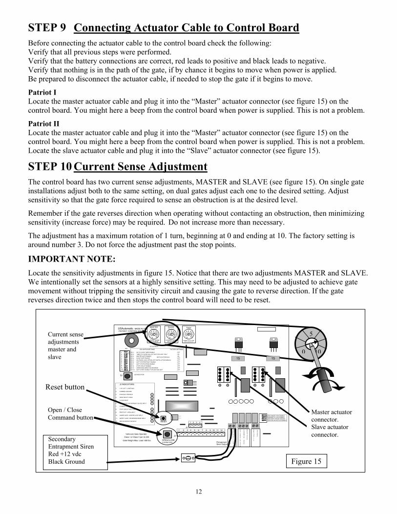
STEP 9 Connecting Actuator Cable to Control Board
Before connecting the actuator cable to the control board check the following: Verify that all previous steps were performed. Verify that the battery connections are correct, red leads to positive and black leads to negative. Verify that nothing is in the path of the gate, if by chance it begins to move when power is applied. Be prepared to disconnect the actuator cable, if needed to stop the gate if it begins to move.
Patriot I Locate the master actuator cable and plug it into the “Master” actuator connector (see figure 15) on the control board. You might here a beep from the control board when power is supplied. This is not a problem.
Patriot II Locate the master actuator cable and plug it into the “Master” actuator connector (see figure 15) on the control board. You might here a beep from the control board when power is supplied. This is not a problem. Locate the slave actuator cable and plug it into the “Slave” actuator connector (see figure 15).
STEP 10 Current Sense Adjustment
The control board has two current sense adjustments, MASTER and SLAVE (see figure 15). On single gate installations adjust both to the same setting, on dual gates adjust each one to the desired setting. Adjust sensitivity so that the gate force required to sense an obstruction is at the desired level.
Remember if the gate reverses direction when operating without contacting an obstruction, then minimizing sensitivity (increase force) may be required. Do not increase more than necessary.
The adjustment has a maximum rotation of 1 turn, beginning at 0 and ending at 10. The factory setting is around number 3. Do not force the adjustment past the stop points.
IMPORTANT NOTE:
Locate the sensitivity adjustments in figure 15. Notice that there are two adjustments MASTER and SLAVE. We intentionally set the sensors at a highly sensitive setting. This may need to be adjusted to achieve gate movement without tripping the sensitivity circuit and causing the gate to reverse direction. If the gate reverses direction twice and then stops the control board will need to be reset.
Open / Close Command button
Secondary Entrapment Siren Red +12 vdc Black Ground
100
5
Siren Output
OPEN/CLOSECOMMAND
Vehicular Gate Operator Gate Weight Max. Load: 650 lbs.
LED INDICATOR S2
RESET
Entrapment
S E C U R I T Y
S H U N T
C O M M O N G N D
M A G L O C K
S O L O N O I D L O C K
C O M M O N G N D
O U T P U T + 1 2 V
O N2
34
1 SOLONOID LOCK ENABLE MAGNETIC LOCK ENABLE SECURITY SHUNT ENABLE MOTION DETECTOR ENABLE
15
5
0 10
TIMER TO CLOSE ADJUSTMENT
Timer
ADJUSTMENT
Class I or Class II per UL325
J2 INDICATORS 1- +12V OUT 1.5 AMP MAX 2- COMMON GROUND 3- PUSH BUTTON INPUT 4- OPEN SAFETY EDGE 5- CLOSE INPUT 6- SECONDARY ENTRAPMENT DEVICE INPUT 7- COMMON GROUND 8- STOP CIRCUIT INPUT N/C 9- FREE EXIT / OPEN INPUT 10- UNDER GATE / CENTER LOOP INPUT 11- SAFETY LOOP / REVERSING EDGE INPUT 12- MOTION DETECTOR INPUT
1 2 3 4 5 6 7 8 9 10 11 12
J2
BOTH ON FOR DUAL
DS1 SWITCH SETTINGS FACTORY SETTINGS
SW-1 AUTO CLOSE TIMER ENABLE OFF SW-2 TIMER TO CLOSE WILL ACTIVATE ON LIMIT ONLY ON SW-3 MASTER GATE ENABLE ON SW-4 SLAVE GATE ENABLE OFF SW-5 SOLENOID LOCK OPTION, SEE INSTALLATION MANUAL OFF SW-6 SOFT STOP RETRACT ENABLE OFF SW-7 SOFT STOP EXTEND ENABLE OFF SW-8 STOP CIRCUIT ENABLE OFF SW-9 OPERATING DIRECTION REVERSE OFF SW-10 SOFT START ENABLE FOR SW6 AND SW7 OFF
1 2 3 4 5 6 7 8 9 10
ON
DS1
PATRIOT CONTROL BOARD USAutomatic MADE IN USA
CURRENT SENSE ADJUSTMENT 0 10
5 MASTER Sensitivity
CURRENT SENSE ADJUSTMENT
0 10
5
SLAVE Sensitivity
15
Master actuator connector. Slave actuator connector.
Figure 15
Reset button
Current sense adjustments master and slave
J5
1 2 3 4
13
STEP 11 Control Board Dipswitch Setting Verification
NOTE: This check must be performed before operating the gate for the first time. Failure to do so may damage the gate operator.
Before operating the gate lets make sure the Patriot control board dipswitches are set correctly for your installation. Locate the dipswitches on the Patriot Control board (see page 17). Factory default dipswitch settings are 2 and 3 on.
Identify you installation below and verify dipswitch settings: Patriot I (Pull to Open) Dipswitches 2, 3 should be in the on position.
Patriot II (Pull to Open) Dipswitches 2, 3, 4 should be in the on position.
Patriot I (Push to Open) Dipswitches 2, 3, 9 should be in the on position. Patriot II (Push to Open) Dipswitches 2, 3, 4, 9 should be in the on position.
NOTE: Push to Open Installations Only:
Push to Open installations do not require rewiring of the actuator harnesses. The Patriot control board dipswitch 9 eliminates the need to do this. Failure to turn dipswitch 9 on will cause improper gate operation. Verify your installation type and verify dipswitch settings.
NOTE: The only thing to remember is that when dipswitch 9 is on, the Limit lights below the actuator plug on the
control board will show open when closed and closed when open.
STEP 12 Operating the Gate NOTE: If soft stop is going to be used disconnect extension tube from gate at this point and turn the
extension screw 6 turns counter clockwise. This will screw the extension screw outward and once reconnected to gate it will not be fully open. Once the gate has cycled, then make necessary limit switch adjustment.
You should be able to stop the motor with the “Open/Close Command” button or the “Reset” button on the control board (see figure 15 on page 12) without having to disconnect the actuator plug from the control board, but in cases of incorrect wiring, the plug can be used as an emergency power shut-off.
If you have an understanding of the sensitivity feature, how to disconnect the actuator plug in an emergency, and have verified the dipswitch settings in step 11 it is time to operate the gate.
NOTE: In most installations the current sense beeper on the control board will beep when the gate begins to operate. This is not a problem. If the beep is constant the gate will stop and reverse direction.
Locate the “Open / Close Command” pushbutton on the Patriot control board, this will be used to operate the gate.
Press the “Open / Close Command” pushbutton to operate the gate. If the gate operates and then reverses direction then a current sense adjustment must be made (see page 12, step 10).
Once current sense adjustment is made press the “Open / Close Command” button again.
The gate should operate without current sensing if adjustment was made correctly. If operator still current senses then readjust the sensitivity. Most installations will operate correctly with a setting of 5. Remember to set slave sensitivity also.
The gate should stop about 24” before the desired stop position. Final adjustment will be made later.
Press the “Open / Close Command” pushbutton again.
The gate should return to the original retracted position (the install position).
14
STEP 13 Making Final Adjustments
If the gate stopped short of the desired stop position on page 13, step 12, then the limit switch needs to be adjusted. Refer to the Limit Switch Adjustment on page 15 to determine which adjustment to make.
STEP 14 Installing Safety Placards (UL-325 requirement)
Mount safety placards on gate. Two signs are provided. Place one sign on each side of the gate where they will be highly visible to anyone on either side of the gate.
STEP 15 Installing Secondary Entrapment Siren (UL-325 requirement) The secondary entrapment siren connects to the control board (figure 15). This siren is very loud and will be activated when the current sense circuit stops the gate twice prior to reaching a fully open or close limit. The siren will operate for 5 minutes before shutting off. The “Reset” button on the control board (see figure 15) can be pushed to turn off the siren, and reset the control board. The control board must be reset using the “Reset” button in either case before the gate will operate.
CAUTION: To reduce the risk of injury, USAutomatic strongly recommends the installation of safety devices such as Photo Eye Sensors, Safety Loops, Safety Edges. Consult an authorized installing dealer or the factory for a complete explanation of options and see the Safety Section of this manual on pages 22 to 25.
15
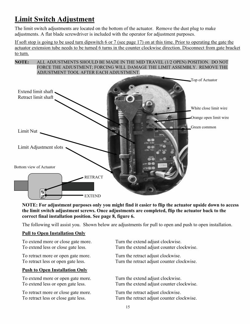
Limit Switch Adjustment
The limit switch adjustments are located on the bottom of the actuator. Remove the dust plug to make adjustments. A flat blade screwdriver is included with the operator for adjustment purposes.
If soft stop is going to be used turn dipswitch 6 or 7 (see page 17) on at this time. Prior to operating the gate the actuator extension tube needs to be turned 6 turns in the counter clockwise direction. Disconnect from gate bracket to turn.
NOTE: ALL ADJUSTMENTS SHOULD BE MADE IN THE MID TRAVEL (1/2 OPEN) POSITION. DO NOT FORCE THE ADJUSTMENT; FORCING WILL DAMAGE THE LIMIT ASSEMBLY. REMOVE THE ADJUSTMENT TOOL AFTER EACH ADJUSTMENT.
NOTE: For adjustment purposes only you might find it easier to flip the actuator upside down to access the limit switch adjustment screws. Once adjustments are completed, flip the actuator back to the correct final installation position. See page 8, figure 6.
The following will assist you. Shown below are adjustments for pull to open and push to open installation.
Pull to Open Installation Only
To extend more or close gate more. Turn the extend adjust clockwise. To extend less or close gate less. Turn the extend adjust counter clockwise.
To retract more or open gate more. Turn the retract adjust clockwise. To retract less or open gate less. Turn the retract adjust counter clockwise.
Push to Open Installation Only
To extend more or open gate more. Turn the extend adjust clockwise. To extend less or open gate less. Turn the extend adjust counter clockwise.
To retract more or close gate more. Turn the retract adjust clockwise. To retract less or close gate less. Turn the retract adjust counter clockwise.
Bottom view of Actuator
RETRACT EXTEND
Extend limit shaft Retract limit shaft Limit Nut Limit Adjustment slots
Top of Actuator White close limit wire Orange open limit wire Green common
16
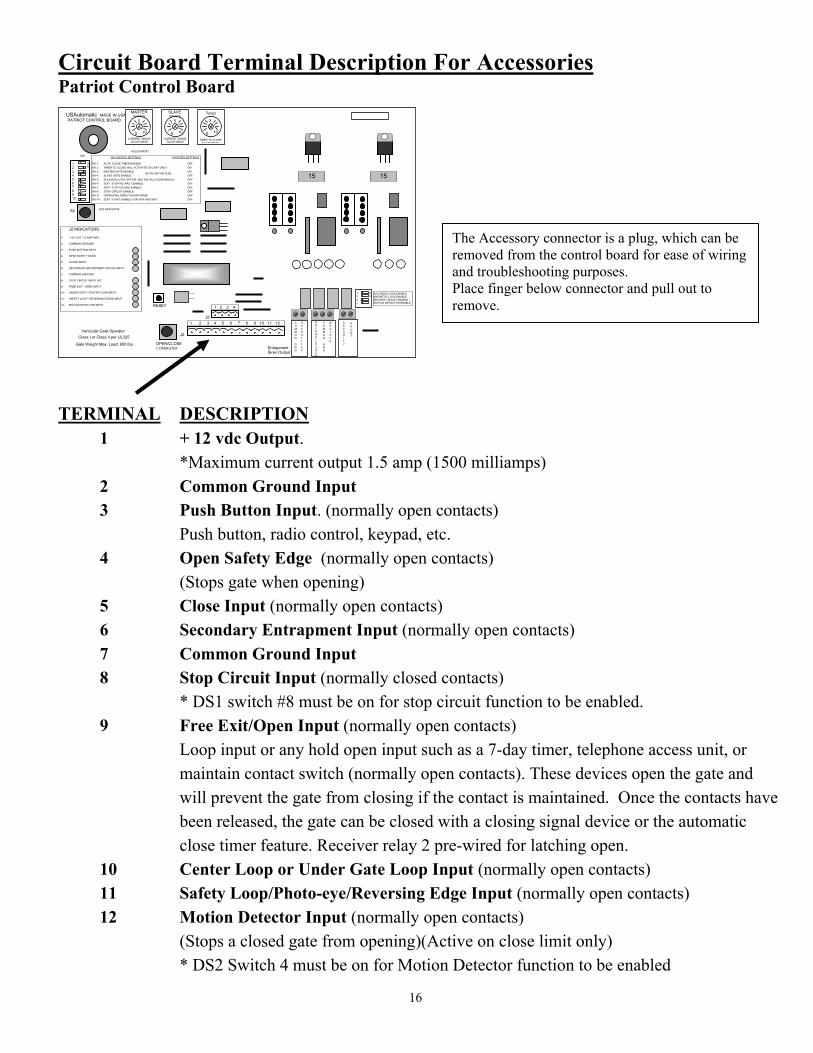
Circuit Board Terminal Description For Accessories Patriot Control Board
TERMINAL DESCRIPTION 1 + 12 vdc Output. *Maximum current output 1.5 amp (1500 milliamps) 2 Common Ground Input 3 Push Button Input. (normally open contacts) Push button, radio control, keypad, etc. 4 Open Safety Edge (normally open contacts) (Stops gate when opening) 5 Close Input (normally open contacts) 6 Secondary Entrapment Input (normally open contacts) 7 Common Ground Input 8 Stop Circuit Input (normally closed contacts) * DS1 switch #8 must be on for stop circuit function to be enabled. 9 Free Exit/Open Input (normally open contacts)
Loop input or any hold open input such as a 7-day timer, telephone access unit, or maintain contact switch (normally open contacts). These devices open the gate and will prevent the gate from closing if the contact is maintained. Once the contacts have been released, the gate can be closed with a closing signal device or the automatic close timer feature. Receiver relay 2 pre-wired for latching open.
10 Center Loop or Under Gate Loop Input (normally open contacts) 11 Safety Loop/Photo-eye/Reversing Edge Input (normally open contacts) 12 Motion Detector Input (normally open contacts)
(Stops a closed gate from opening)(Active on close limit only) * DS2 Switch 4 must be on for Motion Detector function to be enabled
The Accessory connector is a plug, which can be removed from the control board for ease of wiring and troubleshooting purposes. Place finger below connector and pull out to remove.
Siren Output OPEN/CLOSE COMMAND
Vehicular Gate Operator Gate Weight Max. Load: 650 lbs.
LED INDICATOR S2
RESET
Entrapment
S E C U R I T Y
S H U N T
C O M M O N G N D
M A G L O C K
S O L O N O I D L O C K
C O M M O N G N D
O U T P U T + 1 2 V
O N2
34
1 SOLONOID LOCK ENABLE MAGNETIC LOCK ENABLE SECURITY SHUNT ENABLE MOTION DETECTOR ENABLE
15
5 0 10
TIMER TO CLOSE ADJUSTMENT
Timer
ADJUSTMENT
Class I or Class II per UL325
J2 INDICATORS 1- +12V OUT 1.5 AMP MAX 2- COMMON GROUND 3- PUSH BUTTON INPUT 4- OPEN SAFETY EDGE 5- CLOSE INPUT 6- SECONDARY ENTRAPMENT DEVICE INPUT 7- COMMON GROUND 8- STOP CIRCUIT INPUT N/C 9- FREE EXIT / OPEN INPUT 10- UNDER GATE / CENTER LOOP INPUT 11- SAFETY LOOP / REVERSING EDGE INPUT 12- MOTION DETECTOR INPUT
1 2 3 4 5 6 7 8 9 10 11 12
J2
BOTH ON FOR DUAL DS1 SWITCH SETTINGS FACTORY SETTINGS
SW-1 AUTO CLOSE TIMER ENABLE OFF SW-2 TIMER TO CLOSE WILL ACTIVATE ON LIMIT ONLY ON SW-3 MASTER GATE ENABLE ON SW-4 SLAVE GATE ENABLE OFF SW-5 SOLENOID LOCK OPTION, SEE INSTALLATION MANUAL OFF SW-6 SOFT STOP RETRACT ENABLE OFF SW-7 SOFT STOP EXTEND ENABLE OFF SW-8 STOP CIRCUIT ENABLE OFF SW-9 OPERATING DIRECTION REVERSE OFF SW-10 SOFT START ENABLE FOR SW6 AND SW7 OFF
1 2 3 4 5 6 7 8 9 10
ON
DS1
PATRIOT CONTROL BOARD USAutomatic MADE IN USA
CURRENT SENSE ADJUSTMENT 0 10
5 MASTER Sensitivity
CURRENT SENSE ADJUSTMENT 0 10
5 SLAVE Sensitivity
15
J5 1 2 3 4
17
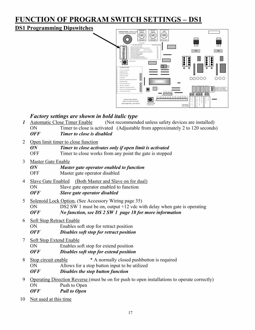
FUNCTION OF PROGRAM SWITCH SETTINGS – DS1 DS1 Programming Dipswitches
Factory settings are shown in bold italic type 1 Automatic Close Timer Enable (Not recommended unless safety devices are installed)
ON Timer to close is activated (Adjustable from approximately 2 to 120 seconds) OFF Timer to close is disabled
2 Open limit timer to close function ON Timer to close activates only if open limit is activated
OFF Timer to close works from any point the gate is stopped
3 Master Gate Enable ON Master gate operator enabled to function OFF Master gate operator disabled
4 Slave Gate Enabled (Both Master and Slave on for dual) ON Slave gate operator enabled to function OFF Slave gate operator disabled
5 Solenoid Lock Option, (See Accessory Wiring page 35) ON DS2 SW 1 must be on, output +12 vdc with delay when gate is operating OFF No function, see DS 2 SW 1 page 18 for more information
6 Soft Stop Retract Enable ON Enables soft stop for retract position OFF Disables soft stop for retract position
7 Soft Stop Extend Enable ON Enables soft stop for extend position OFF Disables soft stop for extend position
8 Stop circuit enable * A normally closed pushbutton is required ON Allows for a stop button input to be utilized
OFF Disables the stop button function
9 Operating Direction Reverse (must be on for push to open installations to operate correctly) ON Push to Open
OFF Pull to Open
10 Not used at this time
Siren Output OPEN/CLOSECOMMAND
Vehicular Gate Operator
Gate Weight Max. Load: 650 lbs.
LED INDICATORS2
RESET
Entrapment
S E C U R I T Y
S H U N T
C O M M O N G N D
M A G L O C K
S O L O N O I D L O C K
C O M M O N G N D
O U T P U T + 1 2 V
O N2
34
1 SOLONOID LOCK ENABLE MAGNETIC LOCK ENABLE SECURITY SHUNT ENABLE MOTION DETECTOR ENABLE
15
5
0 10
TIMER TO CLOSE ADJUSTMENT
Timer
ADJUSTMENT
Class I or Class II per UL325
J2 INDICATORS 1- +12V OUT 1.5 AMP MAX 2- COMMON GROUND 3- PUSH BUTTON INPUT 4- OPEN SAFETY EDGE 5- CLOSE INPUT 6- SECONDARY ENTRAPMENT DEVICE INPUT 7- COMMON GROUND 8- STOP CIRCUIT INPUT N/C 9- FREE EXIT / OPEN INPUT 10- UNDER GATE / CENTER LOOP INPUT 11- SAFETY LOOP / REVERSING EDGE INPUT 12- MOTION DETECTOR INPUT
1 2 3 4 5 6 7 8 9 10 11 12
J2
BOTH ON FOR DUAL
DS1 SWITCH SETTINGS FACTORY SETTINGS
SW-1 AUTO CLOSE TIMER ENABLE OFF SW-2 TIMER TO CLOSE WILL ACTIVATE ON LIMIT ONLY ON SW-3 MASTER GATE ENABLE ON SW-4 SLAVE GATE ENABLE OFF SW-5 SOLENOID LOCK OPTION, SEE INSTALLATION MANUAL OFF SW-6 SOFT STOP RETRACT ENABLE OFF SW-7 SOFT STOP EXTEND ENABLE OFF SW-8 STOP CIRCUIT ENABLE OFF SW-9 OPERATING DIRECTION REVERSE OFF SW-10 SOFT START ENABLE FOR SW6 AND SW7 OFF
1 2 3 4 5 6 7 8 9 10
ON
DS1
PATRIOT CONTROL BOARD USAutomatic MADE IN USA
CURRENT SENSE ADJUSTMENT
0 10
5
MASTER Sensitivity
CURRENT SENSE ADJUSTMENT
0 10
5
SLAVE Sensitivity
15
J5
1 2 3 4
18
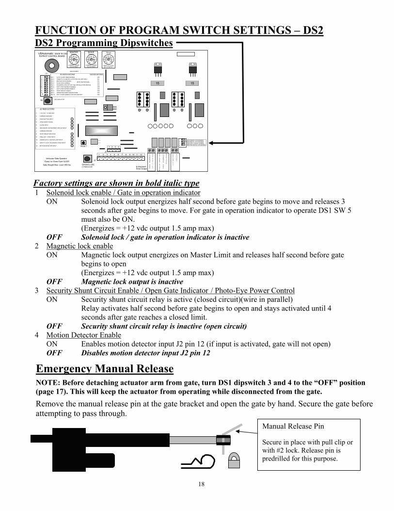
FUNCTION OF PROGRAM SWITCH SETTINGS – DS2 DS2 Programming Dipswitches
Factory settings are shown in bold italic type 1 Solenoid lock enable / Gate in operation indicator
ON Solenoid lock output energizes half second before gate begins to move and releases 3 seconds after gate begins to move. For gate in operation indicator to operate DS1 SW 5 must also be ON.
(Energizes = +12 vdc output 1.5 amp max) OFF Solenoid lock / gate in operation indicator is inactive
2 Magnetic lock enable ON Magnetic lock output energizes on Master Limit and releases half second before gate
begins to open (Energizes = +12 vdc output 1.5 amp max) OFF Magnetic lock output is inactive
3 Security Shunt Circuit Enable / Open Gate Indicator / Photo-Eye Power Control ON Security shunt circuit relay is active (closed circuit)(wire in parallel)
Relay activates half second before gate begins to open and stays activated until 4 seconds after gate reaches a closed limit.
OFF Security shunt circuit relay is inactive (open circuit) 4 Motion Detector Enable
ON Enables motion detector input J2 pin 12 (if input is activated, gate will not open) OFF Disables motion detector input J2 pin 12
Emergency Manual Release
NOTE: Before detaching actuator arm from gate, turn DS1 dipswitch 3 and 4 to the “OFF” position (page 17). This will keep the actuator from operating while disconnected from the gate.
Remove the manual release pin at the gate bracket and open the gate by hand. Secure the gate before attempting to pass through.
Manual Release Pin Secure in place with pull clip or with #2 lock. Release pin is predrilled for this purpose.
Siren Output OPEN/CLOSE COMMAND
Vehicular Gate Operator Gate Weight Max. Load: 650 lbs.
LED INDICATOR S2
RESET
Entrapment
S E C U R I T Y
S H U N T
C O M M O N G N D
M A G L O C K
S O L O N O I D L O C K
C O M M O N G N D
O U T P U T + 1 2 V
O N2
34
1 SOLONOID LOCK ENABLE MAGNETIC LOCK ENABLE SECURITY SHUNT ENABLE MOTION DETECTOR ENABLE
15
5 0 10
TIMER TO CLOSE ADJUSTMENT
Timer
ADJUSTMENT
Class I or Class II per UL325
J2 INDICATORS 1- +12V OUT 1.5 AMP MAX 2- COMMON GROUND 3- PUSH BUTTON INPUT 4- OPEN SAFETY EDGE 5- CLOSE INPUT 6- SECONDARY ENTRAPMENT DEVICE INPUT 7- COMMON GROUND 8- STOP CIRCUIT INPUT N/C 9- FREE EXIT / OPEN INPUT 10- UNDER GATE / CENTER LOOP INPUT 11- SAFETY LOOP / REVERSING EDGE INPUT 12- MOTION DETECTOR INPUT
1 2 3 4 5 6 7 8 9 10 11 12
J2
BOTH ON FOR DUAL DS1 SWITCH SETTINGS FACTORY SETTINGS
SW-1 AUTO CLOSE TIMER ENABLE OFF SW-2 TIMER TO CLOSE WILL ACTIVATE ON LIMIT ONLY ON SW-3 MASTER GATE ENABLE ON SW-4 SLAVE GATE ENABLE OFF SW-5 SOLENOID LOCK OPTION, SEE INSTALLATION MANUAL OFF SW-6 SOFT STOP RETRACT ENABLE OFF SW-7 SOFT STOP EXTEND ENABLE OFF SW-8 STOP CIRCUIT ENABLE OFF SW-9 OPERATING DIRECTION REVERSE OFF SW-10 SOFT START ENABLE FOR SW6 AND SW7 OFF
1 2 3 4 5 6 7 8 9 10
ON
DS1
PATRIOT CONTROL BOARD USAutomatic MADE IN USA
CURRENT SENSE ADJUSTMENT 0 10
5 MASTER Sensitivity
CURRENT SENSE ADJUSTMENT 0 10
5 SLAVE Sensitivity
15
J5 1 2 3 4

19
STEP 16 RADIO EQUIPMENT INSTALLATION AND PROGRAMMING
STEP 16a Oracle Enabled Operators Location of parts in Oracle Dual Frequency Gate Control Unit (“DFGCU”) DFGCU Programming Dipswitches All dipswitches should remain in the off position. If the gate needs to be set for latch open, set feature as follows. Switch 6 – Enable Latch Mode for output 2 Off No action Factory Default On Latch Mode Enabled
STEP 16b Oracle DFGCU and Remote/Transmitter Programming The key fob and the Futura remote/transmitter supplied with the operator transmit on 315 MHz. If installing a Futura Pro remote/transmitter or other Oracle equipment working on 900MHz, please refer to Oracle documentation. For HomeLink or other automobile transmitter programming, see your vehicle manual or dealer. Learning Remote/Transmitter (Key fob or Futura) – 315 MHz
• On the DFGCU, press and hold the learn button down until the red LED light is on solid • Release the learn button and press the learn button again
o When the red LED light starts flashing rapidly, release the learn button • Press the remote/transmitter button you wish to learn to the gate operator
o Multiple remote/transmitters can be programmed one after the other in quick succession • Once all devices are programmed, wait 10 seconds for the red LED light to double blink four times to
signify exiting learn mode
ON
D
IP
Programming Dipswitch Learn Button LED Light
Black Antenna Wire 4-Wire Harness (Connects to J5 on Patriot Control Board)

20
Total Remote/Transmitter Memory Deletion for Key Fob or Futura – 315 MHz
• On the DFGCU, press and hold the learn button down until the LED is on solid • Release the learn button and press the learn button again • Hold the learn button down for 8 seconds or until the red LED light goes steady • Release the learn button • The red LED light will double blink four times to signify exiting learn mode
Latch Mode for DFGCU Turn the DFGCU dispswitch #6 on to enable latch mode for output 2. To latch the gate open, the gate must be in either the fully open or fully closed position. If the gate is closed, press and hold the remote/transmitter button used to operate the gate down until the gate is fully open. Once the gate stops moving, release the remote/transmitter button. If the gate is open, press and hold the remote/transmitter button used to operate the gate down. The gate should start to close. Keep holding the button down and the gate will stop and reverse to the fully open position. Once the gate stops moving, release the remote/transmitter button. Release Gate from Latch Open Condition Press and hold the remote/transmitter button used to operate the gate down for 8 seconds. Then wait for close timer to close gate or press the remote/transmitter a second time to manually close the gate. A command from any Oracle Pro 900 MHz devices installed on the system will release latch mode as well.. 900 MHz devices include: Futura Pro remote/transmitters, push to exit buttons, GAPs, Mini Gaps or wireless keypads. Programming Other Oracle Devices To DFGCU Refer to the programming instructions supplied with your Oracle product for programming instructions.
21
STEP 16c LCR Remote/Transmitter & Receiver (model 433DSR2LC) Programming
The Transmitter and Receiver provided operate at 433 MHz. Receiver can store up to 22 unique transmitter codes.
Transmitter Setup: (It is recommended that the dipswitches be changed from the default setting)
1. Open the battery compartment door and locate the dipswitches. 2. Change the dipswitches to the settings you prefer. Record for future reference.
Transmitter Left Button to Receiver Programming: (standard Open/Stop/Close function)
1. Press and hold the left transmitter button down. Red light on transmitter should be on. 2. On the receiver, push the P1 push-button until the green LD light comes on. 3. Release both buttons. Transmitter left button to receiver programming is complete.
Transmitter Right Button to Receiver Programming: (Hold-Gate-Open) (Only if auto close timer is enabled)
The 2-channel receiver allows for programming the P2 relay from momentary mode (default) to latching mode. Transmitter right button can then be programmed to hold the gate open, over-riding the auto-close feature if activated.
1. Press and hold the right transmitter button down. Red light on transmitter should be on. 2. On the receiver, push the P2 push-button until the green LD light comes on. 3. Release both buttons. Transmitter right button to receiver programming is complete.
Receiver Programming: Relay P2 programming from momentary to latching mode (to hold gate open)
1. On the receiver, push the P2 push-button until the green LD light comes on, then release. Green LD light should be steady.
2. While the green LD light is on, push the P1 push-button down and release. Green LD light should be flashing. Latching mode is set.
Verifying Receiver P2 relay is programmed to latching mode:
1. On the receiver, push the P2 push-button until the green LD light comes on, then release. 2. Green LD light should be flashing. If the green LD light is steady, redo the Receiver Programming section
above.
Resetting receiver P2 relay to momentary mode:
1. On the receiver, push the P2 push-button until the green LD light comes on, then release. Green LD light should be flashing.
2. While the LD light is flashing, push the P1 push-button down and release. Green LD light should be steady. Momentary mode is set.
Erasing Single Transmitter from Receiver Memory:
The dipswitch settings of the transmitter to delete must be known. If known follow the steps below. 1. Set the dipswitches in a transmitter to match the switch settings of the transmitter code to delete. 2. Press and hold the left transmitter button. 3. On the receiver, push the P1 push-button until the green LD light comes on. Then release both. 4. Press and hold the right transmitter button. 5. On the receiver, push the P2 push-button until the green LD light comes on. Then release both. 6. Transmitter is now erased from receiver memory.
Erasing all Transmitters from Receiver Memory:
1. Press the P2 button on the receiver until the green LD light comes on. Then release P2 button. 2. While LD light is on press the P1 and P2 buttons simultaneously and hold until the green LD light begins to
blink slowly. It should blink 4 times then all transmitter codes are erased.
Contact the factory for advanced programming options.
22
SAFETY SECTION
USAutomatic gate operators are certified to UL-325 Vehicular Class I and Class II swing gate standards.
UL-325 identifies four different classes of gate operators these classes are listed below:
Class I: Residential vehicular gate operator- a vehicular gate operator (or system) intended for use in a home of one to four single family dwellings or a garage or parking area associated therewith.
Class II: Commercial/General access vehicular gate operator- a vehicular gate operator (or system) intended for use in a commercial location or building such as multi-family housing unit (five or more single family units), hotel garages, retail store, or other buildings servicing the general public.
Class III: Industrial/Limited access vehicular gate operator- a vehicular gate operator (or system) intended for use in an industrial location or building such as a factory or loading dock area or other locations not intended to serve the general public.
Class IV: Restricted Access vehicular gate operator- a vehicular gate operator (or system) intended for use in a guarded industrial location or building such as an airport security area or other restricted access locations not servicing the general public, in which unauthorized access is prevented via supervision by security personnel.
Patriot I and Patriot II gate operators are intended to be installed as Class I or Class II vehicular gate operators, and the maximum load of each gate leaf should not exceed 650 pounds with a length not to exceed sixteen feet.
SAFETY SECTION
INSTALLATION Install the gate operator when:
The operator is appropriate for the construction of the gate and the usage class is correct for the installation.
All exposed pinch points are eliminated or guarded.
Only install on vehicle gates, pedestrians must be supplied with a separate access opening.
The gate is installed in a location where enough space is supplied between adjacent structures and the gate that when opening or closing the chance of entrapment is reduced.
Swing gates shall not open into public access areas.
The gate is properly installed and swings freely in both directions. Do not over adjust the sensitivity adjustment to compensate for an improper gate installation.
Locate all controls at least six feet away from the gate to eliminate the chance of the person operating the gate from coming in contact with the moving gate. Do not install external buttons, which can be used to operate the gate within the reach of children.
All placards must be installed one on each side of the gate visible in the gate area.
Contact sensors used for secondary entrapment safety devices and their wiring must be installed in a manner protects them from mechanical damage.
Non-Contact sensors used for secondary entrapment safety devices must be located so that the signal from the transmitter to the receiver is not interfered with by adjacent structures. All exposed wiring must also be protected from mechanical damage.
SECONDARY ENTRAPMENT DEVICES
USAutomatic has designed all control boards with secondary entrapment device inputs and secondary safety devices must be installed with all installations. USAutomatic recommends the use of UL-325 listed safety devices.
NOTE: USAutomatic recommends that these devices be CONNECTED after proper gate installation and operation has been verified. Then connect one device and verify proper operation before installing the next device. Ensure that power is disconnected from the control board prior to connecting any wires to the control board.
23
WARNING: TO REDUCE THE RISK OF INJURY OR DEATH
1. READ AND FOLLOW ALL INSTRUCTIONS 2. Never let children operate or play with gate controls. Keep remote/transmitter control away from children. 3. Always keep people and objects away from the gate. 4. NO ONE SHOULD CROSS THE PATH OF A MOVING GATE. 5. Test gate operator monthly. The gate must stop and reverse directions upon contacting a rigid object or
when the secondary entrapment device is activated. 6. After all adjustments have been made to the limit switches, sensitivity (current sense) circuit, secondary
entrapment devices and all other external devices installed the safety devices must be checked again. Failure to adjust and retest the gate operator can increase the risk of injury or death.
7. Verify that the emergency release (manual release) pin can be easily removed. This should only be checked when power is disconnected from the operator.
8. KEEP GATES PROPERLY MAINTAINED. Read the user manual and have a qualified service technician make repairs to the gate hardware.
9. THE ENTRANCE IS TO BE USED BY VEHICLES ONLY. Pedestrians must use a separate entrance. 10. SAVE THESE INSTRUCTIONS
SAFETY SECTION
All safety features required by UL-325 are incorporated in the capabilities of all USAutomatic Control boards and should be utilized, including but not limited to, safety edges, photo electric eyes, reverse sensing, and motion sensing. Cautions - Very Important
Do not attempt to enter the gate area while the gate is moving. Wait until the gate comes to a complete stop. Operate the gate only when it is fully visible, free of persons or obstructions, and properly adjusted. Do not allow children to play in the area of the gate. Do not allow anyone to ride on the gate. Do not allow children to play with the remote/transmitter or any other activation device. Do not attempt to "beat the
gate" while the gate is opening or closing. This is extremely dangerous. Test the current sense feature and all safety devices regularly to insure correct operation. Study this entire Safety Section paying particularly close attention to the entrapment zones shown below and be
aware of these areas not only during use but also during any adjustments to the unit.
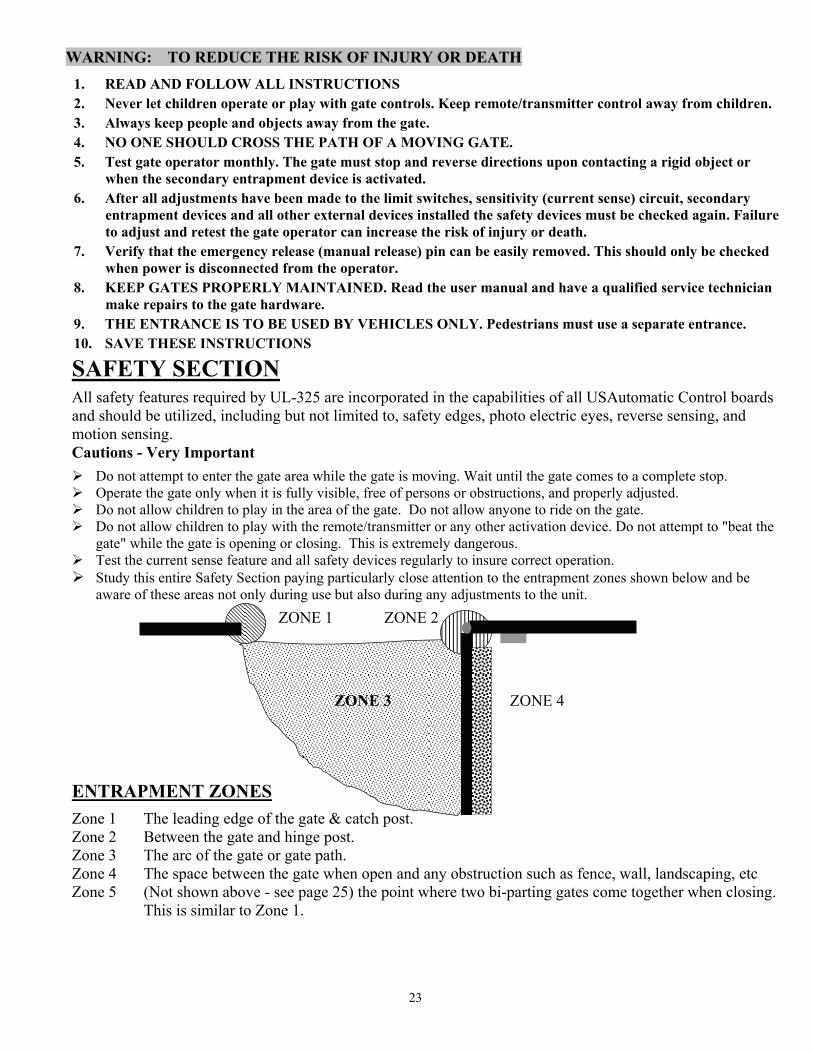
ENTRAPMENT ZONES
Zone 1 The leading edge of the gate & catch post. Zone 2 Between the gate and hinge post. Zone 3 The arc of the gate or gate path. Zone 4 The space between the gate when open and any obstruction such as fence, wall, landscaping, etc Zone 5 (Not shown above - see page 25) the point where two bi-parting gates come together when closing.
This is similar to Zone 1.
ZONE 1 ZONE 2 ZONE 3 ZONE 4
24
SAFETY SECTION Remedies for Safety Concerns
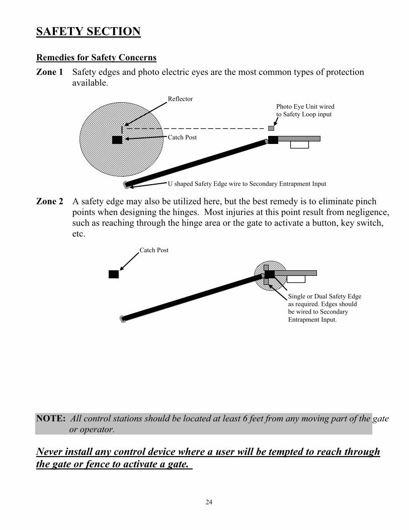
Zone 1 Safety edges and photo electric eyes are the most common types of protection available.
Zone 2 A safety edge may also be utilized here, but the best remedy is to eliminate pinch
points when designing the hinges. Most injuries at this point result from negligence, such as reaching through the hinge area or the gate to activate a button, key switch, etc.
NOTE: All control stations should be located at least 6 feet from any moving part of the gate
or operator. Never install any control device where a user will be tempted to reach through the gate or fence to activate a gate.
Reflector Photo Eye Unit wired to Safety Loop input
Catch Post U shaped Safety Edge wire to Secondary Entrapment Input
Catch Post
Single or Dual Safety Edge as required. Edges should be wired to Secondary Entrapment Input.
25
SAFETY SECTION
Remedies for Safety Concerns
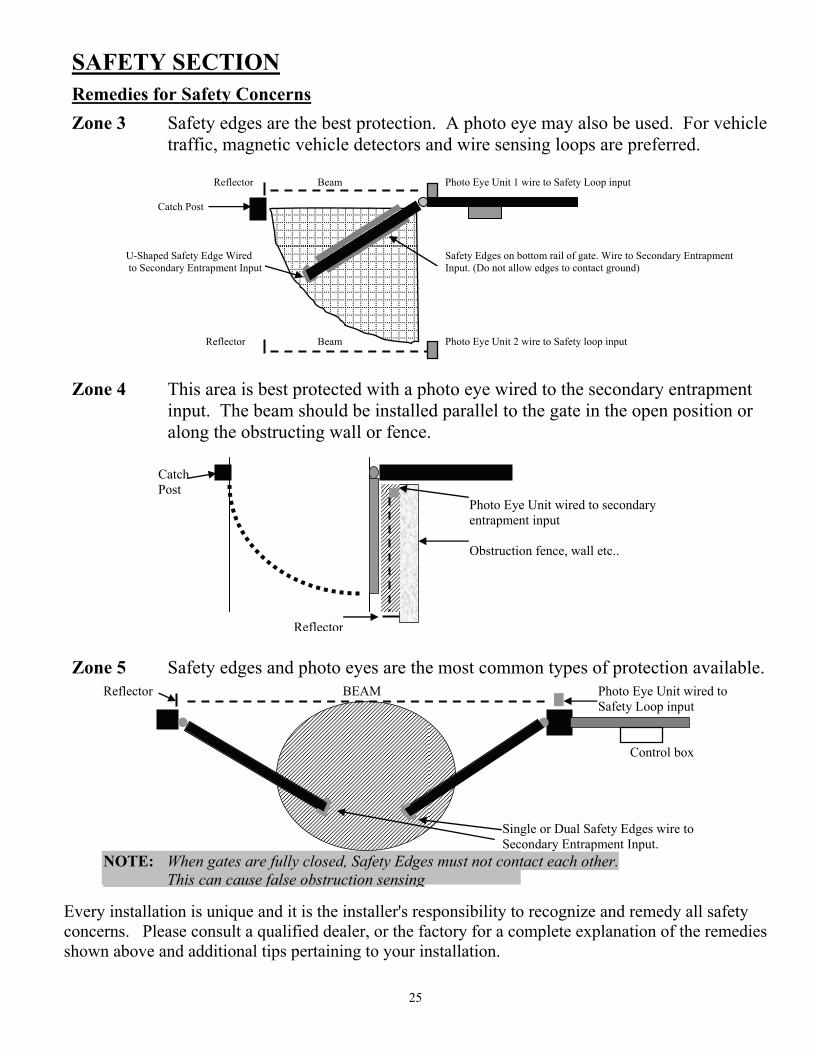
Zone 3 Safety edges are the best protection. A photo eye may also be used. For vehicle traffic, magnetic vehicle detectors and wire sensing loops are preferred.
Zone 4 This area is best protected with a photo eye wired to the secondary entrapment input. The beam should be installed parallel to the gate in the open position or along the obstructing wall or fence.
Zone 5 Safety edges and photo eyes are the most common types of protection available.
Every installation is unique and it is the installer's responsibility to recognize and remedy all safety concerns. Please consult a qualified dealer, or the factory for a complete explanation of the remedies shown above and additional tips pertaining to your installation.
Reflector Beam Photo Eye Unit 1 wire to Safety Loop input Catch Post U-Shaped Safety Edge Wired Safety Edges on bottom rail of gate. Wire to Secondary Entrapment to Secondary Entrapment Input Input. (Do not allow edges to contact ground) Reflector Beam Photo Eye Unit 2 wire to Safety loop input
Catch Post Photo Eye Unit wired to secondary entrapment input B W E A Obstruction fence, wall etc.. A L M L
Reflector
Reflector BEAM Photo Eye Unit wired to Safety Loop input Control box Single or Dual Safety Edges wire to Secondary Entrapment Input. NOTE: When gates are fully closed, Safety Edges must not contact each other. This can cause false obstruction sensing
26
Periodic Service
All gate operators require periodic checking and adjustments, by a qualified technician of the control mechanism for force (load), speed and sensitivity. All external accessories and secondary safety devices must be checked. Secondary safety devices need to be checked at least once a month for proper operation.
Periodic checking is also advised for the following:
1. Check battery connections and verify terminals are clean. Maintenance free batteries recommended. 2. Hinges and pivot points need to be greased. Apply grease to actuator stainless tube as needed. 3. Bolts for correct tightness. 4. Inspect weld points for cracks or other defects. 5. Inspect wiring for cuts, nicks or other defects. 6. Inspect hinge post to ensure it is not moving or twisting. 7. If AC charger is used verify proper charger operation. Refer to charger instructions. 8. Verify that the inside of the control cabinet remains clean and free of insects. Do not spray control
board with bug spray.
Troubleshooting Guide
Introduction
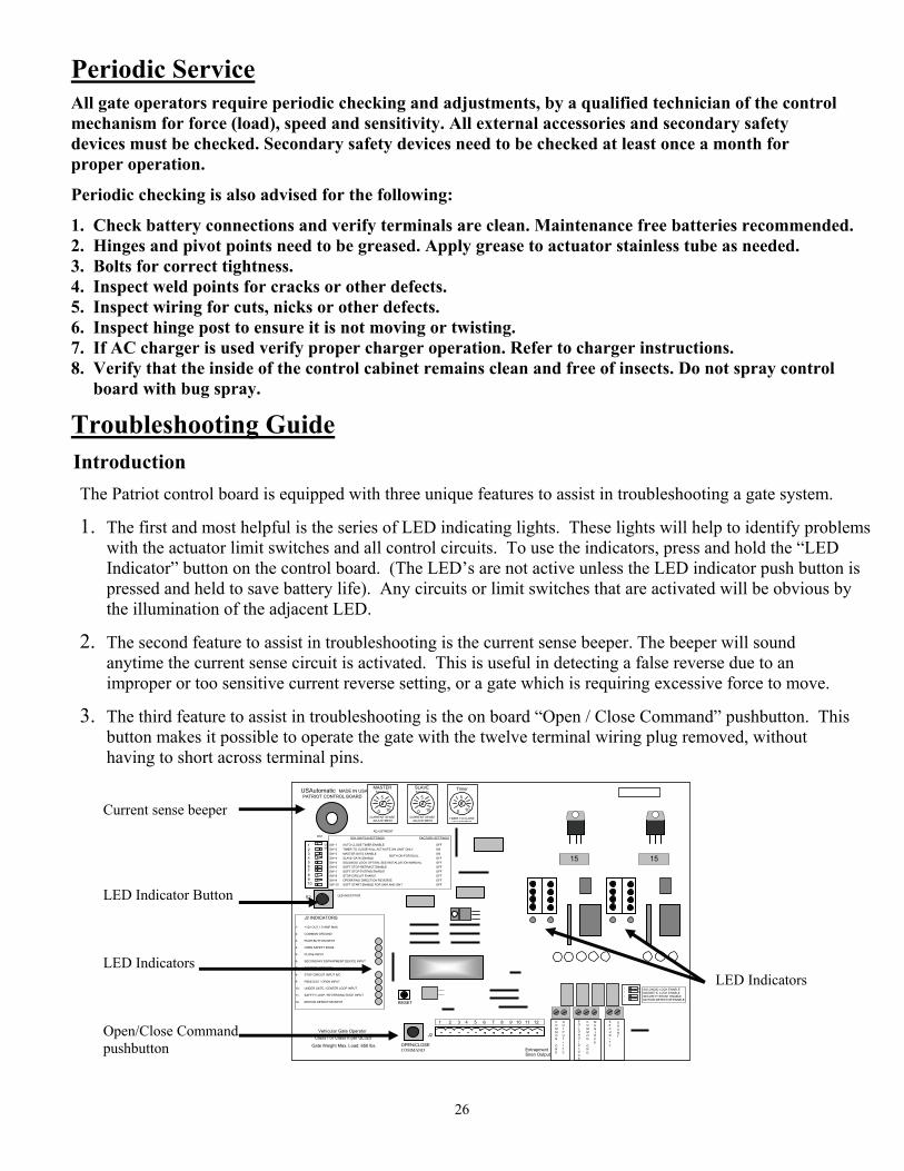
The Patriot control board is equipped with three unique features to assist in troubleshooting a gate system.
1. The first and most helpful is the series of LED indicating lights. These lights will help to identify problems with the actuator limit switches and all control circuits. To use the indicators, press and hold the “LED Indicator” button on the control board. (The LED’s are not active unless the LED indicator push button is pressed and held to save battery life). Any circuits or limit switches that are activated will be obvious by the illumination of the adjacent LED.
2. The second feature to assist in troubleshooting is the current sense beeper. The beeper will sound anytime the current sense circuit is activated. This is useful in detecting a false reverse due to an improper or too sensitive current reverse setting, or a gate which is requiring excessive force to move.
3. The third feature to assist in troubleshooting is the on board “Open / Close Command” pushbutton. This button makes it possible to operate the gate with the twelve terminal wiring plug removed, without having to short across terminal pins.
Siren Output
OPEN/CLOSECOMMAND
Vehicular Gate Operator
Gate Weight Max. Load: 650 lbs.
LED INDICATOR S2
RESET
Entrapment
S E C U R I T Y
S H U N T
C O M M O N G N D
M A G L O C K
S O L O N O I D L O C K
C O M M O N G N D
O U T P U T + 1 2 V
O N 2
34
1 SOLONOID LOCK ENABLE MAGNETIC LOCK ENABLE SECURITY SHUNT ENABLE MOTION DETECTOR ENABLE
15
5
0 10
TIMER TO CLOSE ADJUSTMENT
Timer
ADJUSTMENT
Class I or Class II per UL325
J2 INDICATORS 1- +12V OUT 1.5 AMP MAX 2- COMMON GROUND 3- PUSH BUTTON INPUT 4- OPEN SAFETY EDGE 5- CLOSE INPUT 6- SECONDARY ENTRAPMENT DEVICE INPUT 7- COMMON GROUND 8- STOP CIRCUIT INPUT N/C 9- FREE EXIT / OPEN INPUT 10- UNDER GATE / CENTER LOOP INPUT 11- SAFETY LOOP / REVERSING EDGE INPUT 12- MOTION DETECTOR INPUT
1 2 3 4 5 6 7 8 9 10 11 12
J2
BOTH ON FOR DUAL
DS1 SWITCH SETTINGS FACTORY SETTINGS
SW-1 AUTO CLOSE TIMER ENABLE OFF SW-2 TIMER TO CLOSE WILL ACTIVATE ON LIMIT ONLY ON SW-3 MASTER GATE ENABLE ON SW-4 SLAVE GATE ENABLE OFF SW-5 SOLENOID LOCK OPTION, SEE INSTALLATION MANUAL OFF SW-6 SOFT STOP RETRACT ENABLE OFF SW-7 SOFT STOP EXTEND ENABLE OFF SW-8 STOP CIRCUIT ENABLE OFF SW-9 OPERATING DIRECTION REVERSE OFF SW-10 SOFT START ENABLE FOR SW6 AND SW7 OFF
1 2 3 4 5 6 7 8 9 10
ON
DS1
PATRIOT CONTROL BOARD USAutomatic MADE IN USA
CURRENT SENSE ADJUSTMENT
0 10
5
MASTER Sensitivity
CURRENT SENSE ADJUSTMENT
0 10
5
SLAVE Sensitivity
15
Current sense beeper LED Indicator Button LED Indicators LED Indicators Open/Close Command pushbutton
27
TROUBLESHOOTING SECTION
OUTLINE
1 Single gate will not operate. 2 Dual gate will not operate. 3 Single or Dual gate opens or closes slowly. 4 Gate will not automatically close. 5 Gate begins to open or close, but stops and reverses after a couple of seconds. 6 Single Gate opens correctly then closes immediately or single Gate closes correctly and then opens
immediately. 7 Dual Gate opens correctly then closes immediately or dual Gate closes correctly then opens immediately. 8 Control board 15 amp fuse blows when “Open / Close Command” is given. 9 Remote/Transmitter will not operate the gate. (Multi-Code/Digi-Code and Low Current Receiver models) 10 Photo eye, safety loop or other safety accessory will not reverse the gate when closing. 11 Pressing the “RESET” button only, causes the gate to operate. 12 Gate opens with the transmitter but will not close with the transmitter 13 Gate only operates when the “LED INDICATOR” is pressed. 14 Oracle Remote/Transmitter will not operate the gate.
Terms and Definitions
LED - Light Emitting Diode - small red lights on control board. Control board- Located inside the metal box in the upper right corner. Receiver - Located inside the metal box in the upper left corner - coax cable connected to it. Remote/ Transmitter - Hand held push button, which is used to operate the gate - sends signal to receiver. Actuator - Connected to gate and hinge post - contains the motor, gearbox and extension tube. Connector - Control board has three types of connectors. Two white 8-pin connectors (X1 and X2) are
used to connect actuator to control board, one green 12-pin connector (J2) (located bottom center of control board) to connect third party receivers and accessories to control board and one white 4-pin connector (J5) to connect Oracle Enabled DFGCU to control board. All three are plug type and can be disconnected (unplugged from control board) without disconnecting wires.
Dip Switches - Small switches, which are located on the control board in two places. The primary set DS1, is located in the upper left corner and the secondary set, DS2, is located in the lower right corner of the control board with functions listed beside each. See manual (page 17-18) for more information.
Push Buttons - Three are located on the control board. “Open / Close Command” used to operate the gate, “LED Indicator” used to activate the LED’s and “Reset” used to reset the control board after current sensing twice before a limit is reached.
Note: Never run the actuator while it is disconnected from the gate. Damage may occur. Always have the actuator connected during troubleshooting in case the operator starts working to prevent damaging internal components.
28
1. My single gate will not operate Patriot I:
STEP 1 Remove control box cover. Locate the “Open/Close Command” push button and press it to operate the gate.
STEP 2 Press the “Reset” push button located above the “Open/Close Command” button, then push the “Open/Close command” push button to operate the gate.
STEP 3 When pressing the “Open/Close Command” push button, listen for a clicking sound. If a click is heard, then verify:
The 15-amp fuse located on the control board is good. If not, replace it using the spare located on the control board. Also check the dipswitches (3 and 4) for correct switch settings based on where the actuator is connected to the control board (Master or Slave). If switches are correct and the fuse is good and clicking sound is heard, then the battery needs to be load tested to determine its condition. Charge or replace the battery depending on results. Try connecting jumper cables from your 12vdc vehicle’s battery to the gate operator’s battery as a quick battery test.
STEP 4 Press and hold the “LED Indicator” push button and observe all of the red LED’s (see page 26 for location):
a. If the two limit LED’s located below the actuator plug are both on, the operator will not operate. You must adjust the limit switch (see page 15.) Example: If both limit LED’s are on when the gate is in the closed position, and actuator is connected to the gate, the problem is with the open limit switch. Adjust the open limit until the LED goes off and continue to adjust until the gate is at the desired stopping position. Both LED’s should never be on simultaneously.
b. If any of the LED’s in the lower left corner of the control board are on, then this must be corrected. Locate the accessory which is activated and repair or replace. Disconnecting the accessory will allow the operator to work without the disconnected accessory function.
STEP 5 Disconnect the green J2 connector. Once disconnected, press the “Open/Close Command” button. If gate operates, reconnect the green J2 connector and go to step 4b above.
STEP 6 Verify that DS1 switch 8 is off. STEP 7 Disconnect the actuator connector plugged into the control board (X1 or X2). Reconnect the actuator
connector to the control board in the other connector (X2 or X1.) Locate the DS1 dipswitches on the control board. Reverse the position of switches 3 and 4. Press the “Open/Close Command” button and verify if the gate operates.
Note: Make sure there is a known good fuse in the side of the board the actuator cable is plugged into. STEP 8 Call the factory for more information if the above steps have not worked.
2. My dual gate will not operate Patriot II:
STEP 1 Follow steps 1 through 6 above.
STEP 2 Disconnect both of the actuator connectors plugged into the control board (X1 and X2). Then locate the DS1 dipswitches on the control board. Turn off switch 4 (slide to the left) and turn on switch 3 (slide to right).
Reconnect the connector from the actuator that goes to the gate closest to you. Connect it to the Master (X1) connector on the control board. Press the “Open/Close Command” button and verify that the gate operates.
STEP 3 If the gate operates correctly, disconnect the actuator plug and connect the other actuator plug into the X1 connector. Press the “Open/Close Command” button and verify that the gate operates correctly. At this point you have tested each actuator individually. If both worked correctly then go back to DS1
29
and turn switch 3 off and switch 4 on. Then repeat step 2 and 3 again using X2 connector on control board in place of X1.
STEP 4 If a problem is observed in steps 2 or 3 above most likely it was when the slave actuator (located the greatest distance from control box) was being tested. If this is correct check wiring splices for moisture, correct wiring etc. If the wiring is not in watertight conduit, this is most likely the problem. Tape is not watertight.
3. My gate opens/closes slowly:
NOTE: When the gate is running slow the reason is low battery voltage. Two things need to be considered. Battery condition (replace or charge) and what caused the battery to become discharged.
STEP 1 Determine which situation your operator falls into below:
Solar charged: ensure that you have a 33 amp hour minimum maintenance free battery lead acid, GEL or AGM installed and if accessories are connected (keypads, loop detectors, any device powered by the battery) verify that the current draw needed to power them does not exceed the charging power of the solar panel. Verify that charge controller leads are connected to the battery correctly; panel is facing a Southwestern direction and is not located in a completely shaded area. Inspect panel surface and wires for damage.
Test solar panel for correct voltage and current output. Disconnect charge controller wires from battery. Using a DC voltmeter, measure the dc voltage (should measure about 22 volts) and the dc current (should read about 225 ma or more) in the peak sun period. If either of these readings is incorrect the panel may be defective please call the factory. Reconnect panel to charge controller.
If none of the above check bad, replace all ring terminals connected to the battery that are possibly corroded. If problem persists then remove battery and have it load tested at a battery shop. Replace if bad.
AC charged; ensure that you have a 33 amp hour maintenance free lead acid, GEL or AGM battery. If accessories are connected (keypads, loop detectors, any device powered by the battery) verify that the current draw needed to power them does not exceed the charging power of the charger. Verify that charger leads are connected to the battery correctly; charger is connected to a working approved 110 VAC receptacle. Inspect charger and wires for damage.
NOTE: The USAutomatic multi stage charger does not output any voltage or current when disconnected from the battery. You cannot check charger by disconnecting from battery and measuring voltage output. To check charger output disconnect from battery, measure battery voltage and note voltage reading. Reconnect charger and monitor battery voltage. It should rise above the battery voltage noted above.
STEP 2 The charger has LED indicators (lights) on the faceplate, observe the charger LED’s that are on or not
and refer to the troubleshooting directions furnished with the charger for definitions of different charger LED indicators.
STEP 3 If none of the above check bad then remove battery and have it load tested at a battery shop. Replace if bad.
4. My gate will not automatically close:
NOTE: If DS1 switch 1 is on and switch 2 is off then the gate should automatically close from any position. If switch 2 is also on the gate will only automatically close if the “Open Limit” LED (both “open limit” LED’s for dual gate) is on.
STEP 1 Locate the “Open/Close Command” push button. Press the button to verify that the gate will close. If gate closes correctly, then proceed to the steps below.

30
STEP 2 Verify that DS1 switch 1 is on. If not, turn it on and recheck gate operation. If gate remains open, continue with step 3.
STEP 3 If your installation is a single gate, then only DS1 switch 3 or 4 can be on. If both are on the gate will not automatically close. Turn off the one that is not being used and recheck gate operation.
STEP 4 Locate the “LED Indicator” push button and depress and hold. While pushing the button observe the LED indicators located just below the X1, X2 (master, slave) actuator plugs. Note which LED’s are on. Read note below.
NOTE: The two LED’s located below the X1, X2 actuator plug, when on, represent the closure of the limit
switch. If the left LED is on, then the gate should be in the open position. If the LED on the right is on, then the gate should be in the closed position. If DS1 switch 9 (operating direction reverse) is on then this is reversed. If the LED for the open position is not on when the gate is fully opened, then the auto close will not work. The limit switches need to be adjusted.
STEP 5 Locate the “LED Indicator” push button and depress and hold. While pushing the button inspect the LED indicators located on the control board (lower left corner) and note which LED’s are on. If any LED’s are on disconnect the green J2 connector from the control board. Press the “Open/Close Command” push button to close the gate. Press the button again to open the gate fully and verify the automatic close is working.
STEP 6 If gate automatically closes correctly, then the accessory connected to the J2 connector that is activated (LED is on) needs to be repaired or replaced.
5. Gate begins to open or close but stops and reverses after a couple of seconds.
STEP 1 Remove control box cover and locate the Patriot control board. Locate the sensitivity adjustment potentiometer (see page 12) located on the control board. The white center is adjustable and needs to be turned in a clockwise direction.
STEP 2 Normally a setting of 5 will operate most gates. If your gate requires a setting above 8, there is a good chance that your gate has a mechanical problem which needs to be corrected. Possible causes are incorrect hinges, gate touching the ground, gate not level or the actuator arm connected to the gate is bent. Identify and correct problem.
6. Single Gate opens or closes correctly, then immediately reverses direction:
STEP 1 This is most likely caused by an incorrect limit switch adjustment. The limit switch adjustments are located on the bottom of the actuator motor housing, behind the removable rubber plug. Locate the limit switch adjustment screws and determine which one needs to be adjusted (see page 15). Operate the gate. Once it reaches the desired open or close position, stop the gate in that position using the transmitter or “Open/Close Command” push button located on the Patriot control board.
STEP 2 Locate the “LED Indicator” push button located on the left side of the Patriot control board. Also locate the open and close LED indicators below the actuator plug on the Patriot control board. The left LED represents the open position and the right LED represents the close position. (See note below)
STEP 3 With the gate in the desired open or close position, press and hold the “LED Indicator.” Observe which of the LED lights come on. If your gate is in the desired open position, then the LED on the left should be on. If not, adjust the retract limit switch (see page 15) until the LED comes on. If gate was in the close position adjust the extend limit switch until the close LED comes on.
NOTE: If DS1 switch 9 is turned on, then the open and close LED’s are reversed. Open LED represents the closed position and the close LED represents the open position.

31
STEP 4 Once adjusted correctly, the open LED should be on when the gate is opened and the close LED should be on when the gate is closed.
STEP 5 If the LED’s will not come on contact the factory.
7. Dual Gate opens or closes correctly then immediately reverses direction:
STEP 1 This is most likely caused by an incorrect limit switch adjustment. First determine which gate is in need of adjustment.
STEP 2 Locate the DS1 switches on the Patriot control board. Switch 3 and 4 should be turned on for a dual gate, turn off switch 4. This will disable one gate.
STEP 3 Operate the gate and verify that it stops in the correct position. If so then turn switch 4 back on and turn switch 3 off. Operate the other gate now and verify that it stops in the correct position. One or both should not stop in the correct position.
STEP 4 Once the gate that needs adjustment is identified (possibly both) refer to problem 6, steps 1 through 5 for instructions.
8. Control board 15 amp fuse blows when Open/Close command is given.
STEP 1 Fuses blow primarily for one reason, the gate cannot move. Causes might be something keeping the gate from moving, the gate is trying to move in the wrong direction due to incorrect limit switch setting or there might be a wiring problem. A wiring problem is most likely in a splice that might have been made during installation or it could be in the actuator housing.
STEP 2 Open the control box and locate the Patriot control board, locate the 2 LED’s under the actuator connector on the control board. Press the “LED Indicator” push button and hold it in, observe the LED’s and determine if the open limit or close limit LED is on. Then determine if the correct LED is on for the gate position. For example if the left LED is on that is the open limit and the gate should be in the open position. The right LED represents the closed position. See note under section 4, page 30.
STEP 3 If the open limit LED is on and the gate is closed, a command to operate the gate will try to close the gate more, which can blow a fuse. If the close limit LED is on and the gate is open a command to operate the gate will try to open more, which can blow a fuse. In either case, the limit switches need to be adjusted and then the cause for them becoming misadjusted needs to be determined. The cause generally has to do with wiring; bad actuator plug connection at the Patriot control board or too much adjustment has been made during installation.
STEP 4 If a wiring problem is suspected, the orange, white and green wires are the ones to concentrate on. Check all splices and verify actuator connector is connected at the control board.
STEP 5 If the actuator is suspected of being bad either due to an internal wiring problem or a motor problem, call the factory for further troubleshooting and return information.
9. Remote/Transmitter will not operate the gate (Identify radio equipment being used)
STEP 1 Open the control box and locate the Patriot control board. Locate the “LED Indicator” push button and the “Push Button Input” LED. Push and hold the “LED Indicator” push button, then press the transmitter button and observe the “Push Button Input” LED. The LED should come on while the transmitter button is depressed.
Note: Step 2 for Multi-Code / Digi-Code radio equipment
STEP 2 If the “Push Button LED” did not come on, make sure that the green J2 connector on the control board is securely connected. Replace the battery in the transmitter and verify that the dipswitches located in the transmitter (above battery) are set identical to the ones located in you receiver. Remove the receiver cover by squeezing the sides and locate the dipswitches inside.
Note: STEP 2a for Low Current Receiver radio equipment
32
STEP 2a If the “Push Button Input” LED did not come on in step 1 then make sure that the green J2 connector on the control board is securely connected, replace the battery in the transmitter and verify that the transmitter is programmed to operate the receiver (refer to page 21 “LCR Remote/Transmitter Programming .”)
STEP 3 If the “Push Button Input” LED in step 1 did come on and the gate did not operate then locate the “Open/Close Command” button located at the bottom center of the Patriot control board. Press the “Open/Close Command” button and note gate operation.
STEP 4 If the gate did not operate in step 3, verify the 15-amp fuse on the Patriot control board adjacent to the actuator plug being used is not blown, (a fuse can be blown and look good) replacing is the best way to verify fuse is good.
STEP 5 If the gate did not operate in step 3 and the fuse was good in step 4, most likely a safety accessory connected to the green J2 connector is active. Verify this by depressing the “LED Indicator” push button and observe the LED’s located in the lower left corner of the Patriot control board. If an LED is on, identify the accessory connected to the corresponding J2 connector pin and correct the problem.
STEP 6 Other possibilities are: the open and close limit LED’s are both on at the same time, adjust limit switches; control board is defective or battery could be too weak to operate the gate. Please call the factory for help identifying the cause.
10. Photo-eye, safety loop or other safety accessory will not reverse the gate when closing or hold the gate open
STEP 1 The first thing to check is the accessory wiring. The accessory needs power (+12 vdc) wired to battery positive terminal or to J2 pin 1 on the Patriot control board. It also needs ground, which can be wired to the battery negative terminal or to J2 pin 2 or 7 on the Patriot control board. The other two connections are the “N/O (Normally Open) and Common ground”. The common ground can be connected to the battery or to J2 pin 2 or 7 on the Patriot control board. The N/O connection must be connected to J2 pin 11 “Safety Loop / Reversing Edge Input”. If the accessory is connected as described above it should reverse a closing gate or hold a gate open if the accessory is activated.
STEP 2 To determine if the accessory is working correctly and that the Patriot control board is receiving the signal, locate the “LED Indicator” push button and the “Safety Loop / Reversing Edge Input” LED (located in the lower left corner of the Patriot control board).
STEP 3 Press and hold the “LED indicator” push button and observe the “Safety Loop / Reversing Edge Input” LED. Activate the accessory in question (if photo-eye, break the beam.) If the accessory is working properly, the LED light should come on when the device is activated. If the device does not turn on the LED light, check the wiring on the J2 connector and check J2 connector connection to the Patriot control board. If wiring is good, then the accessory is not operating correctly. Repair.
STEP 4 If the “Safety Loop / Reversing Edge Input” LED comes on and the gate does not reverse direction when closing, call the factory for other possible causes and return information.
11. Pressing the “RESET” button only, causes the gate to operate
STEP 1 This problem is probably due to a bad receiver. First locate the “LED Indicator” push button on the Patriot control board. Then locate the “Push Button Input” LED located in the lower left corner of the Patriot control board.
STEP 2 Press the “LED Indicator” button and observe the “Push Button Input” LED. If the LED comes on then the receiver relay is stuck closed and needs to be repaired or replaced.
STEP 3 If the “Push Button Input” LED does not come on, call the factory for further troubleshooting and return information.
33
12. Gate opens using transmitter, but will not close using transmitter (Low Current Receiver only) STEP 1 The problem is most likely the programming of the Low Current Receiver (P2 relay is programmed
to latch mode) STEP 2 On the Patriot control board locate press and hold the “LED Indicator” pushbutton. STEP 3 Look in the lower left corner of the Patriot control board and note any LED’s that are on. STEP 4 If the “OPEN INPUT” is on then the receiver (P2) is programmed to latch mode. STEP 5 Go to page 21 “Resetting receiver P2 relay to momentary mode” STEP 6 If this does not correct the problem return to troubleshooting section 4 and perform steps 1-6. STEP 7 If problem is not corrected; call the factory for further troubleshooting. 13. Gate only operates when the “LED INDICATOR” is pressed. STEP 1 An accessory wiring problem or a bad control board can cause this. This problem can be intermittent
and will take a little patience in locating the problem. STEP 2 Verify that the problem exists when using the “Open /Close Command” on the control board. Press
the “Open/Close Command” push button and verify gate will not operate. STEP 3 Press the “Led Indicator” on the control board and hold then press the “Open/Close Command” push
button on the control board. If the gate operates, proceed to step 4. STEP 4 Remove the J2 accessory-wiring plug from the control board. This connector can be disconnected
from the control board by placing a finger under the plug and pulling to remove. STEP 5 Press the “Open/Close Command” push button and verify gate operation. If gate operates then
reconnect the J2 connector and verify gate operation using the “Open/Close Command” push button. If gate fails to operate when the J2 connector is reconnected then the problem is most likely in the accessory wiring. Most likely there is a bad ground connection on the accessory. Verify all wiring on the accessories connected to the J2 connector.
STEP 6 If gate fails to operate when the J2 connector is disconnected, then the control board is most likely the problem. Please contact the factory for further troubleshooting options.
NOTE: Keep in mind that this is an intermittent problem and it might be necessary to try this a few times to verify the problem.
NOTE: If you have a DC volt meter, check the following. Set the gate to the fully open or close position and verify that an open or close limit LED is on when the led indicator is pressed. Take voltage reading on the following J2 connector terminals. Pin 3,4,5,6,8,9,10,11,12. The reading should be 5 vdc. A reading of approximately 2 or 3 vdc indicates a problem. Call the factory for corrective action. This could indicate a bad LED on the corresponding J2 connector pin which can be resolved by removing the LED light from the control board.
14. Oracle Remote/Transmitter will not operate the gate STEP 1 Press and hold the LED indicator on the control board STEP 2 Press the Remote/Transmitter button to operate the gate, the push button input LED on the control
board should light. If it does not verify wiring from DFGCU receiver to J5 is not damaged. STEP 3 If wiring checked good, verify batteries in remote/transmitter are good. Replace battery if necessary. STEP 4 If problem persist refer to page 19 and try “Learning remote/transmitter” again. STEP 5 If relearning the remote/transmitter to DFGCU receiver does not correct problem, call factory for
help.
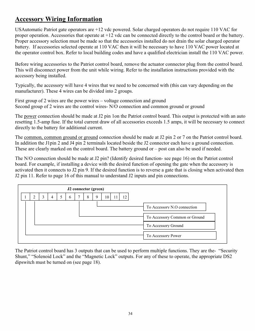
34
Accessory Wiring Information USAutomatic Patriot gate operators are +12 vdc powered. Solar charged operators do not require 110 VAC for proper operation. Accessories that operate at +12 vdc can be connected directly to the control board or the battery. Proper accessory selection must be made so that the accessories installed do not drain the solar charged operator battery. If accessories selected operate at 110 VAC then it will be necessary to have 110 VAC power located at the operator control box. Refer to local building codes and have a qualified electrician install the 110 VAC power. Before wiring accessories to the Patriot control board, remove the actuator connector plug from the control board. This will disconnect power from the unit while wiring. Refer to the installation instructions provided with the accessory being installed. Typically, the accessory will have 4 wires that we need to be concerned with (this can vary depending on the manufacturer). These 4 wires can be divided into 2 groups. First group of 2 wires are the power wires – voltage connection and ground Second group of 2 wires are the control wires- N/O connection and common ground or ground The power connection should be made at J2 pin 1on the Patriot control board. This output is protected with an auto resetting 1.5-amp fuse. If the total current draw of all accessories exceeds 1.5 amps, it will be necessary to connect directly to the battery for additional current. The common, common ground or ground connection should be made at J2 pin 2 or 7 on the Patriot control board. In addition the J1pin 2 and J4 pin 2 terminals located beside the J2 connector each have a ground connection. These are clearly marked on the control board. The battery ground or – post can also be used if needed. The N/O connection should be made at J2 pin? (Identify desired function- see page 16) on the Patriot control board. For example, if installing a device with the desired function of opening the gate when the accessory is activated then it connects to J2 pin 9. If the desired function is to reverse a gate that is closing when activated then J2 pin 11. Refer to page 16 of this manual to understand J2 inputs and pin connections. The Patriot control board has 3 outputs that can be used to perform multiple functions. They are the- “Security Shunt,” “Solenoid Lock” and the “Magnetic Lock” outputs. For any of these to operate, the appropriate DS2 dipswitch must be turned on (see page 18).
J2 connector (green)
1 2 113 4 5 9 6 7 8 10 12
To Accessory N.O connection
To Accessory Common or Ground
To Accessory Ground
To Accessory Power
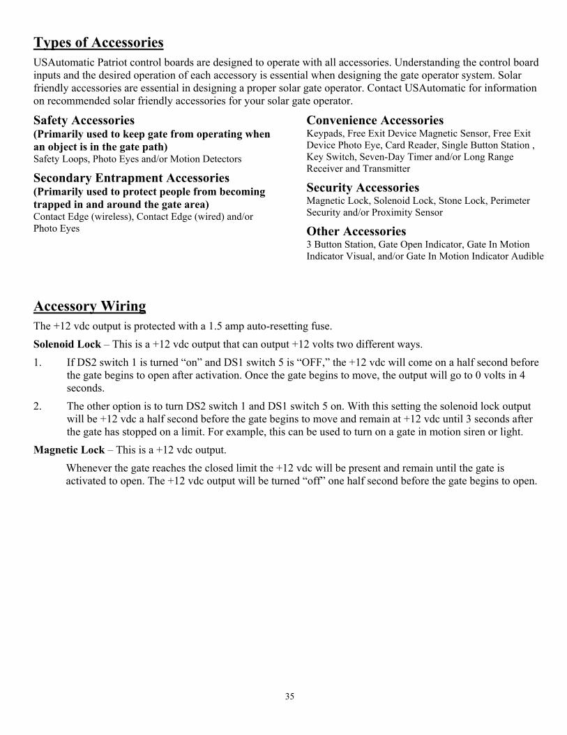
35
Types of Accessories
USAutomatic Patriot control boards are designed to operate with all accessories. Understanding the control board inputs and the desired operation of each accessory is essential when designing the gate operator system. Solar friendly accessories are essential in designing a proper solar gate operator. Contact USAutomatic for information on recommended solar friendly accessories for your solar gate operator.
Safety Accessories (Primarily used to keep gate from operating when an object is in the gate path) Safety Loops, Photo Eyes and/or Motion Detectors
Secondary Entrapment Accessories (Primarily used to protect people from becoming trapped in and around the gate area) Contact Edge (wireless), Contact Edge (wired) and/or Photo Eyes
Convenience Accessories Keypads, Free Exit Device Magnetic Sensor, Free Exit Device Photo Eye, Card Reader, Single Button Station , Key Switch, Seven-Day Timer and/or Long Range Receiver and Transmitter
Security Accessories Magnetic Lock, Solenoid Lock, Stone Lock, Perimeter Security and/or Proximity Sensor
Other Accessories 3 Button Station, Gate Open Indicator, Gate In Motion Indicator Visual, and/or Gate In Motion Indicator Audible
Accessory Wiring
The +12 vdc output is protected with a 1.5 amp auto-resetting fuse.
Solenoid Lock – This is a +12 vdc output that can output +12 volts two different ways.
1. If DS2 switch 1 is turned “on” and DS1 switch 5 is “OFF,” the +12 vdc will come on a half second before the gate begins to open after activation. Once the gate begins to move, the output will go to 0 volts in 4 seconds.
2. The other option is to turn DS2 switch 1 and DS1 switch 5 on. With this setting the solenoid lock output will be +12 vdc a half second before the gate begins to move and remain at +12 vdc until 3 seconds after the gate has stopped on a limit. For example, this can be used to turn on a gate in motion siren or light.
Magnetic Lock – This is a +12 vdc output.
Whenever the gate reaches the closed limit the +12 vdc will be present and remain until the gate is activated to open. The +12 vdc output will be turned “off” one half second before the gate begins to open.
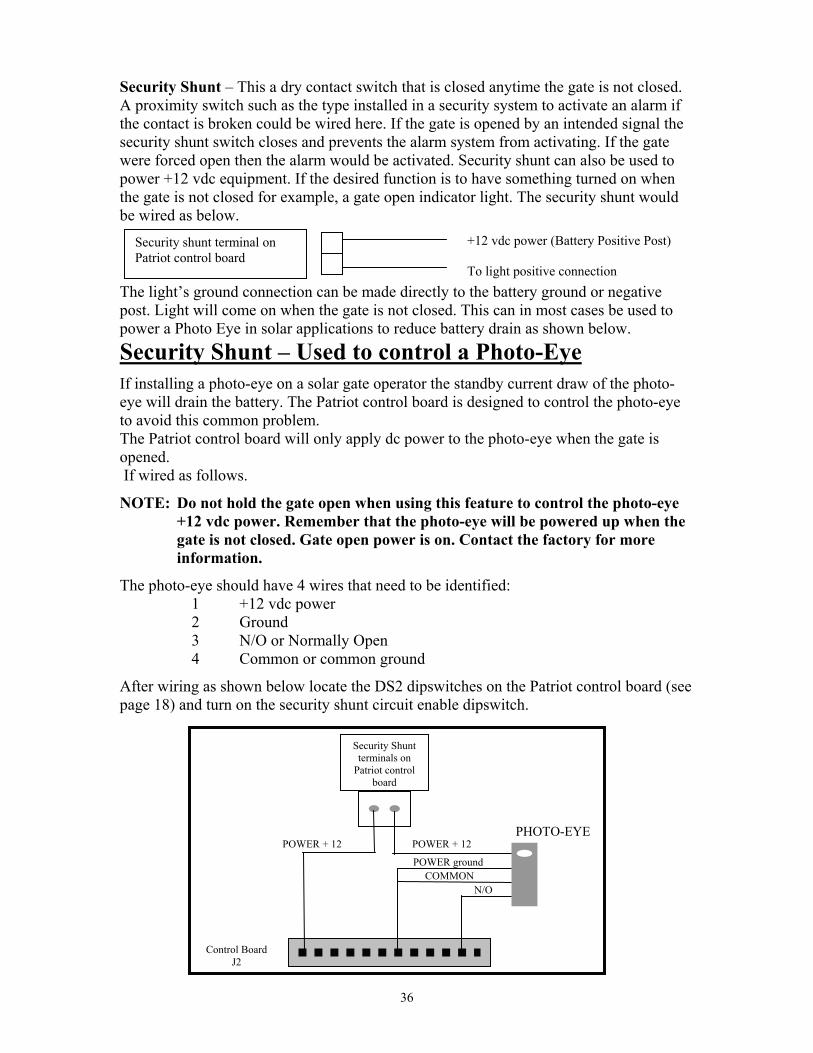
36
Security Shunt – This a dry contact switch that is closed anytime the gate is not closed. A proximity switch such as the type installed in a security system to activate an alarm if the contact is broken could be wired here. If the gate is opened by an intended signal the security shunt switch closes and prevents the alarm system from activating. If the gate were forced open then the alarm would be activated. Security shunt can also be used to power +12 vdc equipment. If the desired function is to have something turned on when the gate is not closed for example, a gate open indicator light. The security shunt would be wired as below. The light’s ground connection can be made directly to the battery ground or negative post. Light will come on when the gate is not closed. This can in most cases be used to power a Photo Eye in solar applications to reduce battery drain as shown below. Security Shunt – Used to control a Photo-Eye
If installing a photo-eye on a solar gate operator the standby current draw of the photo-eye will drain the battery. The Patriot control board is designed to control the photo-eye to avoid this common problem. The Patriot control board will only apply dc power to the photo-eye when the gate is opened. If wired as follows.
NOTE: Do not hold the gate open when using this feature to control the photo-eye +12 vdc power. Remember that the photo-eye will be powered up when the gate is not closed. Gate open power is on. Contact the factory for more information.
The photo-eye should have 4 wires that need to be identified: 1 +12 vdc power 2 Ground 3 N/O or Normally Open 4 Common or common ground
After wiring as shown below locate the DS2 dipswitches on the Patriot control board (see page 18) and turn on the security shunt circuit enable dipswitch.
+12 vdc power (Battery Positive Post)
To light positive connection
Security shunt terminal on Patriot control board
PHOTO-EYE POWER + 12
Security Shunt terminals on
Patriot control board
POWER + 12
POWER ground COMMON
N/O
Control Board J2

37

38
USAutomatic
PATRIOT I PATRIOT II
Limited 5 Year Warranty
The PATRIOT Gate Operator is warranted to be free of defects in materials or workmanship for a period of
5 years from date of purchase on the electronic control board and 36 months on all other components. Any
part, parts, or complete unit found to be defective within this period would, at the manufacturer's option be
repaired or replaced at no charge if returned freight prepaid. New or factory rebuilt replacement parts are
warranted for the remaining portion of the original warranty period. The manufacturer will pay for
standard ground freight on the return of the repaired or replaced items under this warranty. The
manufacturer will not be responsible for field service or labor charges incurred in the removal or
replacement of defective parts. Furthermore, the manufacturer will not be responsible for incidental or
consequential damages.
This warranty is in lieu of all other warranties expressed or implied and shall be considered void if damage
was due to improper use or installation, connection to an improper power source, or if caused by fire, flood,
lightning and other acts of nature, or by vehicles or vandalism.
This warranty gives you specific legal rights, and you may have other rights, which vary from state to state.
Some states do not allow limitations or exclusions of implied warranties so these may not apply to you.
CUT HERE
RETAIN FOR YOUR RECORDS
USAutomatic, LTD 118 Hillside Drive
Lewisville, Texas 75057 Toll Free 1-888-204-0174
Model: Date of Purchase: Serial #: Purchased from: Name: Address: City: State: Zip:
• Serial number can be found by removing cover and looking on control board.
34
USAutomatic
PATRIOT I PATRIOT II
Garantía Limitada de 5 Anos El operador de portón PATRIOT tiene garantía de no tener defectos en los materiales o fabricación por el periodo de 5 años desde la fecha de compra en el tablero de control y 36 meses en todos los demás componentes. Cualquier otra parte, partes, o unidad completa que estén defectuosas durante este tiempo será, a la opción del fabricante reparada o cambiada sin cargos si es pagado por adelantado Les partes de fábrica nuevas o reconstruidas que sean cambiadas son garantizados por el resto del tiempo de la garantía original. El fabricante pagará el transporte estándar por tierra en los artículos reparados o substituidos bajo esta garantía. El fabricante no se hará responsable por los cargos de trabajo por quitar o cambiar cualquier parte que sea defectuosa. Además, el fabricante no será responsable de daños fortuitos o consecuentes.
Esta garantía es en lugar de el resto de las garantías expresadas o implicadas y será considerada anulada si los daños eran debidos al uso o a la instalación incorrecta, conexión a una fuente de energía incorrecta, o si estuvo causada por un fuego, inundación, relámpagos y otros actos de la naturaleza, o por los actos de vandalismo.
Esta garantía le da los derechos legales específicos, y usted puede tener otros derechos, que varían de estado a estado. Algunos estados no permiten limitaciones o exclusiones de garantías implicadas así que éstos pueden no aplicarse a usted.
*Numero de Serial esta en el cubierto del tablero de control.
GUARDE ESTE FRAGMENTO PARA SUS EXPEDIENTES USAutomatics, LTD 118 Hillside Drive
Lewisville, Texas 75057 Toll Free 1-800-204-0174
Modelo: ____________________ Fecha de Venta: ______________________ Numero de Serial: ___________ Comprado de: ________________________ Nombre”_________________________________________________________ Domicilio: _______________________________________________________ Ciudad: _____________________Estado:___________Código Postal: _______

33

32
Programando el transmisor y el receptor (modelo 433 DSR2LC)
El transmisor y el receptor operan en 433 MHz. El receptor puedo guardar hasta 22 códigos únicos para el transmisor.
Disposición del transmisor: (Es recomendado cambiar el ajuste del valor por omisión del conmutador DIP.)
1. Abra el compartimiento de la batería y encuentre los conmutadores DIP. 2. Cambie los ajustes de los conmutadores DIP a sus preferencias. Apunte para futura consulta.
El botón izquierdo del transmisor para programar el receptor: (el función standard Abrir/Parar/Cerrar) 1. Oprima el botón izquierdo del transmisor. La luz roja del transmisor debe verse. 2. En el receptor, oprima el botón P1 hasta que la luz verde con LD se vea. 3. Suelte los dos botones. El programar del botón izquierdo del transmisor al receptor está completo.
El botón derecho del transmisor para programar el receptor: (Deje-Abierto-Portón) (Nada más si el reloj para cerrar automáticamente está puesto)
El dos canal receptor permite programar el relé P2 del modo momentáneo (la posición del valor por omisión) al modo de retención. El botón derecho del transmisor se puede programar para dejar el portón abierto, para que no se cierre automáticamente el portón.
1. Oprima el botón derecho hasta que la luz roja se vea en el transmisor. 2. En el receptor, oprima el botón P2 hasta que la luz verde con LD se vea. 3. Suelte los dos botones. El botón derecho del transmisor al receptor está programado.
Programando el receptor: Programando el relé P2 de modo momentáneo a modo retención (para dejar el portón abierto).
1. En el receptor, oprima el botón P2 hasta que la luz verde con LD se vea, luego suéltelo. La luz verde debe estar fija. 2. Mientras que la luz verde esté, oprima el botón P1 y luego suéltelo. La luz verde debe destellar. El modo de
retención está puesto.
Verificando el receptor P2 está programado al modo de retención: 1. En el receptor, oprima el botón P2 hasta que la luz verde con LD se vea, entonces deje de apretarlo. 2. La luz verde con LD debe destallar. Si la luz está fija, rehaga la sección Programando el receptor.
Reajustando el receptor relé P2 al modo momentáneo: 1. En el receptor, oprima el botón P2 hasta que la luz verde con LD se vea, entonces deje de apretarlo. La luz verde con
LD debe destellar. 2. Mientras la luz está destellando, oprima el botón P1 y luego deje de apretarlo. La luz verde con LD debe estar fija.
El modo momentáneo está puesto.
Borrando sólo un transmisor de la memoria del receptor:
Debe saber los ajustes del conmutador DIP del transmisor que se va borrar. Si sabe los ajustes, siga con los pasos siguientes. 1. Oprima los conmutadores DIP en el transmisor para que hagan juego con los códigos del transmisor que se van a
borrar. 2. Apriete y no levante el dedo del botón izquierdo del transmisor. 3. En el receptor, oprima el botón P1 hasta que la luz verde con LD se vea. Luego deje de oprimir los dos botones. 4. Oprima y no deje de apretar el botón izquierdo del transmisor. 5. En el receptor, oprima el botón P2 hasta que la luz verde con LD se vea. Luego deje de oprimir los dos botones. 6. El transmisor está borrando la memoria del receptor.
Borrando todo los transmisores de la memoria del receptor: 1. Oprima el botón P2 en el receptor hasta que la luz verde con LD se vea. Luego deje de apretar el botón P2. 2. Mientras que la luz verde con LD se vea, oprima los botones P1 y P2 simultáneamente hasta que la luz verde con LD
empieza parpadear despacio. La luz debe parpadear cuatro veces y luego todos los códigos del transmisor están borrados.
Contacte la fábrica para opciones avanzadas para programar.
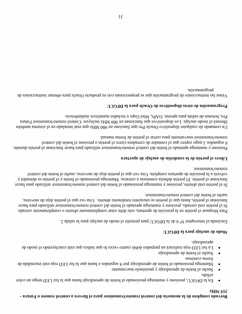
31
Borrado completo de la memoria del control remoto/transmisor para el llavero a control remoto o Futura - 315 MHz
• En la DFGCU, presione y mantenga presionado el botón de aprendizaje hasta que la luz LED tenga un color sólido.
• Suelte el botón de aprendizaje y presiónelo nuevamente • Mantenga presionado el botón de aprendizaje por 8 segundos o hasta que la luz LED roja esté encendida de
forma continua • Suelte el botón de aprendizaje • La luz LED roja realizará un parpadeo doble cuatro veces lo que indica que está concluyendo el modo de
aprendizaje. Modo de anclaje para la DFGCU Encienda el interruptor Nº 6 de la DFGCU para permitir el modo de anclaje para la salida 2. Para bloquear el portón en la posición de apertura, este debe estar completamente abierto o completamente cerrado. Si el portón está cerrado, presione y mantenga apretado el botón del control remoto/transmisor utilizado para hacer funcionar el portón, hasta que el portón se encuentre totalmente abierto. Una vez que el portón deje de moverse, suelte el botón del control remoto/transmisor. Si el portón está abierto, presione y mantenga presionado el botón del control remoto/transmisor utilizado para hacer funcionar el portón. El portón debería comenzar a cerrarse. Mantenga presionado el botón y el portón se detendrá y volverá a la posición de apertura completa. Una vez que el portón deje de moverse, suelte el botón del control remoto/transmisor. Libere el portón de la condición de anclaje de apertura Presione y mantenga apretado el botón del control remoto/transmisor utilizado para hacer funcionar el portón durante 8 segundos. Luego espere que el contador de cerradura cierre el portón o presione el botón del control remoto/transmisor nuevamente para cerrar el portón de forma manual. Un comando de cualquier dispositivo Oracle Pro que funcione en 900 MHz que esté instalado en el sistema también liberará el modo anclaje. Los dispositivos que funcionan en 900 MHz incluyen: Control remoto/transmisor Futura Pro, botones de salida para apretar, GAPs, Mini Gaps o teclados numéricos inalámbricos. Programación de otros dispositivos de Oracle para la DFGCU Véase las instrucciones de programación que se proporcionan con su producto Oracle para obtener instrucciones de
programación.
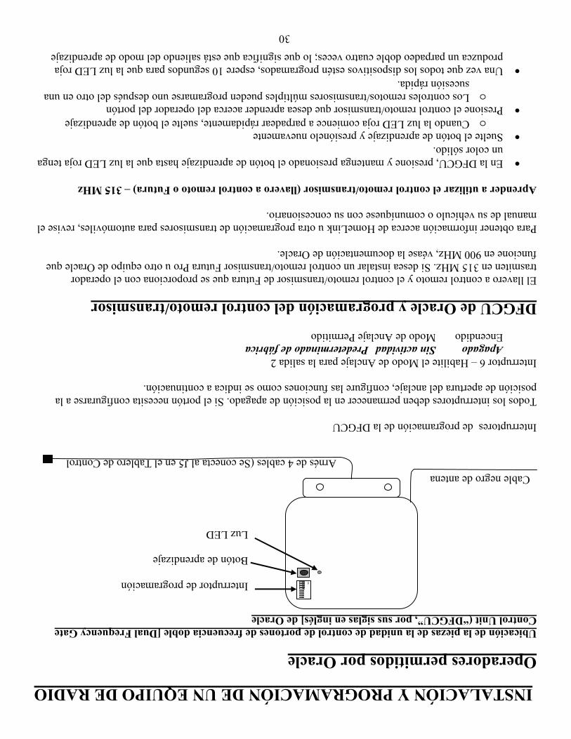
30
INSTALACIÓN Y PROGRAMACIÓN DE UN EQUIPO DE RADIO Operadores permitidos por Oracle Ubicación de la piezas de la unidad de control de portones de frecuencia doble [Dual Frequency Gate Control Unit (“DFGCU”, por sus siglas en inglés] de Oracle Interruptores de programación de la DFGCU Todos los interruptores deben permanecer en la posición de apagado. Si el portón necesita configurarse a la posición de apertura del anclaje, configure las funciones como se indica a continuación. Interruptor 6 – Habilite el Modo de Anclaje para la salida 2 Apagado Sin actividad Predeterminado de fábrica Encendido Modo de Anclaje Permitido DFGCU de Oracle y programación del control remoto/transmisor El llavero a control remoto y el control remoto/transmisor de Futura que se proporciona con el operador trasmiten en 315 MHz. Si desea instalar un control remoto/transmisor Futura Pro u otro equipo de Oracle que funcione en 900 MHz, véase la documentación de Oracle. Para obtener información acerca de HomeLink u otra programación de transmisores para automóviles, revise el manual de su vehículo o comuníquese con su concesionario. Aprender a utilizar el control remoto/transmisor (llavero a control remoto o Futura) – 315 MHz
• En la DFGCU, presione y mantenga presionado el botón de aprendizaje hasta que la luz LED roja tenga un color sólido.
• Suelte el botón de aprendizaje y presiónelo nuevamente o Cuando la luz LED roja comience a parpadear rápidamente, suelte el botón de aprendizaje
• Presione el control remoto/transmisor que desea aprender acerca del operador del portón o Los controles remotos/transmisores múltiples pueden programarse uno después del otro en una
sucesión rápida. • Una vez que todos los dispositivos estén programados, espere 10 segundos para que la luz LED roja
produzca un parpadeo doble cuatro veces; lo que significa que está saliendo del modo de aprendizaje
ON
Interruptor de programación Botón de aprendizaje Luz LED
Cable negro de antena Arnésde 4 cables (Se conecta al J5 en el Tablero de Control

29
Alambres Adicionales La potencia +12vdc está protegido con un fusible de 1.5 amp de reajuste automático. Candado Solenoide - Este es de potencia de +12 voltios que puede producir +12 voltios de dos formas diferentes.
1. El interruptor 1 del DS2 esta “ENCENDIDO” y el interruptor 5 del DS1 esta “APAGADO” los +12 voltios se encenderán medio segundo antes que el portón se empiece a abrir después de ser activado. En cuanto el portón se empiece a mover la potencia estará en 0 voltios en 4 segundos.
2. La otro opción es que de vuelta al interruptor 1 del DS2 y el interruptor 5 del DS1. Con este ajuste la potencia del candado solenoide será +12 voltios dc medio segundo antes de que comience a abrirse el portón después de ser activado y se mantiene con +12 voltios dc hasta 3 segundos después de que esta el portón completamente abierto. Cuando es activado el portón para cerrase la potencia del solenoide será 12 voltios dc medio segundo antes de que el portón empiece a moverse y se mantiene así hasta 3 segundos después de que el portón este completamente cerrado. Por ejemplo esto puede ser usado para prender la sirena o luz de movimiento del portón.
Candado Magnético- Es de potencia de+12 voltios dc.
Cuando el portón este en el limite cerrado los +12 voltios dc estará presente y permanecerá hasta que el portón sea activado para abrir. La potencia de +12 voltios dc estará “APAGADO” medio segundo antes de que el portón comience a abrirse.
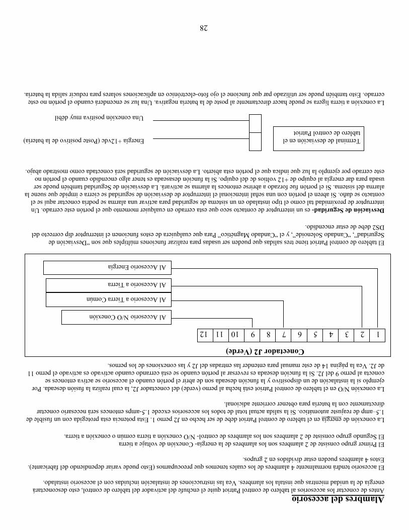
28
Alambres del accesorio Antes de conectar los accesorios al tablero de control Patriot quite el enchufe del activador del tablero de control, esto desconectará energía de la unidad mientras que instala los alambres. Vea las instrucciones de instalación incluidas con el accesorio instalado. El accesorio tendrá normalmente 4 alambres de los cuales tenemos que preocuparnos (Esto puede variar dependiendo del fabricante). Estos 4 alambres pueden estar divididos en 2 grupos. El Primer grupo consiste de 2 alambres son los alambres de la energía- Conexión de voltaje a tierra El Segundo grupo consiste de 2 alambres son los alambres de control- N/O conexión a tierra común o conexión a tierra. La conexión de energía en el tablero de control Patriot debe de ser hecho en J2 perno 1. Esta potencia esta protegida con un fusible de 1.5–amp de reajuste automático. Si la salida actual total de todos los accesorios excede 1.5-amps entonces será necesario conectar directamente con la batería para obtener corriente adicional. La conexión N/O en el tablero de control Patriot está hecha al perno (verde) del conectador J2, la cual realiza la fusión deseada. Por ejemplo si la instalación de un dispositivo y la función deseada son de abrir el portón cuando el accesorio se activa entonces se conecta al perno 9 del J2. Si la función deseada es reversar al portón cuando se está cerrando cuando activado es activado el perno 11 de J2. Vea la página 14 de este manual para entender las entradas del J2 y las conexiones de los pernos. El tablero de control Patriot tiene tres salidas que pueden ser usadas para realizar funciones múltiples que son “Desviación de Seguridad”, “Candado Solenoide”, y el “Candado Magnético” Para que cualquiera de estos funcionen el interruptor dip correcto del DS2 debe de estar encendido. Desviación de Seguridad- es un interruptor de contacto seco que esta cerrado en cualquier momento que el portón este cerrado. Un interruptor de proximidad tal como el tipo instalado en un sistema de seguridad para activar una alarma se podría conectar aquí se el contacto se daño. Si abren el portón con una señal intencional el interruptor de desviación de seguridad se cierra e impide que suene la alarma del sistema. Si el portón fue forzado a abrirse entonces la alarma se activará. La desviación de Seguridad también puede ser usada para dar energía al equipo de +12 voltios dc del equipo. Si la función desaseada es tener algo encendido cuando el portón no este cerrado por ejemplo la luz que indica que el portón esta abierto. La desviación de seguridad será conectada como mostrado abajo. Terminal de desviación en el Energía +12vdc (Poste positivo de la batería)
tablero de control Patriot Una conexión positiva muy débil
La conexión a tierra ligera se puede hacer directamente al poste de la batería negativa. Una luz se encenderá cuando el portón no este cerrado. Esto también puede ser utilizado par que funcione el ojo foto-electrónico en aplicaciones solares para reducir salida la batería.
Conectador J2 (Verde)
1 2 11 3 4 5 9 6 7 8 1012
Al AccesorioN/O Conexión
Al Accesorio a Tierra Común
Al Accesorio a Tierra
Al Accesorio Energía

27
11. Solamente con presionar el botón de “Reajuste”, hace que funcione el portón
PASO 1 Este problema es probablemente debido a un recibidor malo. Primero ubique el botón “Indicador LED” en el tablero de control Patriot. Después ubique el LED “Botón de Energía” que se encuentra en la esquina de debajo de mano izquierda del tablero de control Patriot.
PASO 2 Presione el botón “Indicador LED” y observe el LED “Botón de Energía”. Si el LED se prende entonces la transmisión del recibidor esta pegado y necesita ser reparado o substituido.
PASO 3 Si el LED “Botón de Energía” no se prende, llame a la fábrica para que le den información adicional de causas de problemas.
12. El control remoto/transmisor no hará funcionar el portón PASO 1 Presione y mantenga presionado el indicador LEDen el tablero de control PASO 2 Presione el botón del control remoto/transmisor para hacer funcionar el portón, la entrada LED del
botón en el tablero de control debe estar encendida. Si no está encendida, verifique que el cableado que va desde el receptor de la DFGCU hasta el conector J5 no esté dañado.
PASO 3 Si el cableado se encuentra en buenas condiciones, verifique que las baterías del control remoto/transmisor estén en buenas condiciones. Si es necesario, cambie las baterías.
PASO 4 Si continúa el problema, véase la página 19 y revise "Aprender a utilizar el control remoto/transmisor” nuevamente.
PASO 5 Si al volver a revisar las secciones del control remoto/transmisor hasta receptor DFGCU no solucionan el problema, llame al fabricante para obtener ayuda.
Información de Adicional de los Alambres Operadores de portón USAutomatics Patriot funcionan con 12 vdc, operadores de carga solar no requieren 110 vac para funcionar. Accesorios que funcionar con 12 vdc pueden ser conectados directamente al tablero de control o a la batería. Debe hacer una selección apropiada de accesorio para que el accesorio que sea instalado no le acabe la carga a una batería cargada solarmente.
Si los accesorios seleccionados funcionan con 110 vac entonces será necesario tener energía de 110 vac en la caja de control del operador. Refiérase a los códigos locales de edificios y haga que un electricista calificado le instale los 110 vac.
Tipos de Accesorios Los tableros de control Patriot de USAutomatic son diseñados para funcionar con todos tipos de accesorios. Entender las entradas del tablero de control y el funcionamiento deseado de cada accesorio es esencial al diseñar el sistema del operador del portón.
Accesorios de Seguridad (Sobre todo usado para que no funcione el portón cuando este un objeto en camino del portón) Lazos de Seguridad Ojos Foto-Electrónicos Detector de Movimiento
Accesorios Secundarios de Atrapamiento (Sobre todo usado para proteger que no se vaya a atrapar las personas en y alrededor del área del portón) Bordes de contacto (sin hilos) Bordes de contacto (con hilos) Ojos Foto-Electrónicos
Accesorios de Conveniencia Teclados Numéricos Sensor magnético del dispositivo libre de salida Ojo Foto-Electrónico del dispositivo libre de salida Lector de tarjetas Estación de botón sencillo Interruptor de Llave Contador de Siete-Días Recibidor y Transmisor de largo alcance
Accesorios de Seguridad Candado Magnético Candado Solenoide Candado de piedra Sensor de Seguridad en Perímetro Cercano
Otros Accesorios Estación de tres botones Indicador de portón abierto Indicador visual de movimiento del portón Indicador Audible de movimiento del portón

26
generalmente tiene que ver con los alambres, conexión de enchufe del activador malo en el tablero de control Patriot o demasiados ajustes fueron hechos durante la instalación.
PASO 4 Si hay un problema en los alambres debe de concentrarse en los alambres anaranjado, blanco, y el verde. Revise todos los empalmes y verifique que este conectado el enchufe del activador al tablero de control.
PASO 5 Si sospecha que el activador esta mal debido a problemas internos de alambres o un problema del motor, llame a la fábrica para que le divulgue más información acerca de problemas.
9. Transmisor no opera el portón
PASO 1 Abra la caja de control y ubique el tablero de control Patriot. Ubique el botón “Indicador LED” y el LED de “Energía del Botón.” Presione y sostenga el botón “Indicador LED”, y luego presione el botón de transmisor y observe el “Botón LED”. El LED debe de encenderse mientras que el botón del transmisor esta presionado.
PASO 2 Si el “Botón de LED” no se encendió entonces asegúrese que el conectador verde J2 en el tablero de control esta bien conectado, cambie la batería de 9 voltios en el transmisor y verifique que los interruptores dip ubicado en el transmisor (arriba de la batería) se instalan igual a los que están situados en su recibidor. Quite la cubierta del recibidor con apretar los lados y ubique los interruptores adentro.
PASO 3 Si el “Botón de Energía” del LED en PASO 1 no se encendió y el portón no funcionó entonces ubique el botón “Para Abrir/ Cerrar” ubicado en el centro de abajo del tablero de control Patriot. Presione el botón “Para Abrir/ Cerrar” y note como funciona del portón.
PASO 4 Si el portón no funcionó en el PASO 3 verifique que el fusible de 15-amp en el tablero de control adyacente del enchufe del activador el que esta siendo usado no se haya fundido, (un fusible puede estar fundido y se ve bien) la mejor forma de verificar que un fusible esta bueno es cambiándolo.
PASO 5 Si el portón no funcionó en PASO 3 y el fusible estaba bueno en PASO 4 entonces es muy probable que un accesorio de seguridad conectado al conector verde J2 esta activo. Verifique esto con presionar el botón “Indicador LED” y observe los LED’s localizados in la esquina de debajo de mano izquierda del tablero de control Patriot. Si un LED esta encendido identifique el accesorio conectado al perno de conectador correspondiente al J2 y corrija el problema.
PASO 6 Otras causas son posibles, los dos limites de los LED’s para abrir y cerrar están encendidos al mismo tiempo, si es así ajuste los interruptores de limite. El tablero de control puede ser defectuoso; la batería puede ser muy débil para operar el portón. Por favor llame a la fábrica identificando la causa para pedir asistencia.
10. El ojo foto-electrónico, lazo de seguridad, u otros accesorios de seguridad no hacen que se reverse el portón cundo se esta cerrando o cuando el portón abierto se detiene
PASO 1 La primera cosa para revisar son los alambres del accesorio. El accesorio necesita potencia (+12vdc) conectado a la batería al terminal positivo o al J2 perno 1 en el tablero de control Patriot. También necesita conexión a tierra, que puede ser conectado a la batería o al J2 perno 2 o 7 en el tablero de control Patriot. Las otras dos conexiones son los “N/O y conexión a tierra común”. La conexión a tierra común puede ser conectada a la batería o a J2 perno 2 o 7 en el tablero de control Patriot. La conexión N/O debe de ser conectado a J2 perno 11 “Lazos de seguridad/ Entrada del borde contrario”. Si el accesorio esta conectado como es descrito arriba debe de reversar un portón que se este cerrando o detener un portón abierto si está activado el accesorio.
PASO 2 Ahora para determinar si el accesorio funciona correctamente y el tablero de control Patriot esta recibiendo la señal, ubique el botón “Indicador LED” y el LED “Lazos de seguridad/ Entrada del borde contrario” (Ubique en la esquina baja de mano izquierda del tablero de control Patriot).
PASO 3 Presione y detenga el botón “Indicador LED” y observe el LED “Lazos de seguridad/ Entrada del borde contrario”. Active el accesorio en cuestión (si ojo foto-electrónico interrumpa el rayo) si el accesorio esta funcionando correctamente la luz del LED debe de prenderse cuando se activa el dispositivo. Si el dispositivo no prende la luz del LED entonces revise los alambres, conector J2 conectado al tablero de control Patriot. Si los alambres están bien entonces el accesorio no esta operando correctamente. Repare el accesorio y revise de nuevo.
PASO 4 Si el LED “Lazos de seguridad/ Entrada del borde contrario” se encendió y el portón no se mueve en la dirección contraría cuando se esta cerrando, llame a la fábrica para que le den información adicional de causas de problemas.

25
incorrectas, el portón tocando la tierra; el portón no esta a nivelo el brazo del activador conectado al portón hasido doblado. Identifique y corrija el problema.
6. Portón Sencillo se abre o cierra correctamente e inmediatamente se va a la dirección contraria:
PASO 1 Esto es causado muy probablemente por un ajuste incorrecto del interruptor de limite. Los ajustes del interruptor de límite se encuentran en el fondo de la cubierta del motor del activador, detrás del enchufe de goma desprendible. Ubique los tornillo de los ajustes del interruptor de limite y determine cual necesita ser ajustado (Vea página 13). Opere el portón y en cuanto este en la posición abierta o cerrado deseada pare el portón en esa posición, usando el transmisor o el botón “Para Abrir/ Cerrar” localizado en el tablero de control Patriot.
PASO 2 Ubique el botón “Indicador LED” que se encuentra en el lado izquierdo del tablero de control Patriot. También ubique los indicadores LED de abrir y cerrar debajo del enchufe del activador en el tablero de control Patriot. El LED de mano izquierda representa la posición abierta y el LED de mano derecha representa la posición cerrada. (Vea nota de continuación)
PASO 3 Con el portón en la posición abierta o cerrada deseada presione y sostenga el “Indicador LED” y observe cual de las luces del LED se encienden. Si su portón esta en la posición abierta deseada entonces el LED de lado izquierdo debe de estar encendido, si no ajuste el interruptor de limite de retractar (Vea página 13) hasta que el LED se encienda. Si el portón estaba en la posición cerrada ajuste el interruptor de límite para extender hasta que el LED se encienda.
NOTA: Si el interruptor 9 del DS1 esta encendido, entonces los LED’s de abrir y cerrar están al revés. LED abierto representa la posición cerrada y el LED cerrado representa la posición abierta.
PASO 4 En cuanto este ajustado correctamente el LED para abrir debe de estar encendido cuando el portón este abierto y el LED de Cerrar debe de estar encendido cuando el portón este cerrado.
PASO 5 Si los LED’s no se encienden contacte la fabrica.
7. Portón doble se abre o cierra correctamente e inmediatamente se va a la dirección contraria:
PASO 1 Esto es causado muy probablemente por un ajuste incorrecto del interruptor de limite. Primero debe determinar cual portón necesita ser ajustado.
PASO 2 Ubique los interruptores del DS1 en el tablero de control Patriot. Los interruptores 3 y 4 deben de estar encendidos para un portón doble, apague el interruptor 4, esto desactivará uno de los portones.
PASO 3 Opere el portón y verifique que se para en la posición correcta, si es así encienda de nuevo el interruptor 4 y apague el interruptor 3. Ahora opere el otro portón y verifique que se pare en la posición correcta. Uno o los dos no deben de pararse en la posición correcta.
PASO 4 En cuanto identifique el portón que necesita ser ajustado (posiblemente los dos) refiérase a las instrucciones de problema 6 arriba, pasos del 1 al 5.
8. Fusible de 15 amp del tablero de control se funde cunado dan la orden de abrir/cerrar.
PASO 1 Los fusibles se funden sobre todo por una razón, el portón no se puede mover. Las causas pueden ser que algo no permite que se mueva el portón, el portón esta intentando moverse en sentido contrario debido a un ajuste incorrecto del interruptor de limite o pudo haber un problema con los alambres. Un problema de los alambres posiblemente se pudo haben hecho durante la instalación en un empalme o podría estar en la cubierta del activador.
PASO 2 Abra la caja de control y ubique el tablero de control Patriot, ubique los 2 LED’s debajo del enchufe del activador en el tablero de control. Presione el botón “Indicador LED” y sosténgalo, observe los LED’s y determine si el LED de limite de abrir o limite de cerrar esta encendido. Y luego determine si el LED correcto esta encendido para la posición del portón. Por ejemplo si el LED de mano izquierdo esta encendido este es el límite de abrir y el portón debe de estar abierto. El LED la de mano derecha representa la posición cerrada. Vea nota a continuación de problema 4 arriba.
PASO 3 Si el limite del LED de abrir esta encendido y el portón esta cerrado si una orden de operación es dada el portón tratara de cerrarse mas, esto puede fundir un fusible. Si esta encendido el LED de limite y el portón esta abierto una orden de operación tratara de abrir el portón mas, esto puede causar que se funda un fusible. En cualquier caso los interruptores deben de ser ajustados y se debe determinan la causa por la que se desajustaran. La causa

24
defectuoso. Si ninguno de los de arriba estaban malos quite la batería y lleve la a una tienda de baterías para que le prueben la carga. Reemplázala si es necesario.
Cargador AC, asegúrese que tenga instalada una batería de ciclo profundo clasificado con un mínimo de 33 amp por hora. Si los accesorios son conectados (teclados numéricos, detectores de lazo, cualquier dispositivo que funciona por la batería) verifique que no necesiten mas poder del que tiene el cargador. Verifique que las guías del cargador están conectadas a la batería correctamente; cargador esta conectado con un receptáculo aprobado de 110 VAC. Examine la el cargador y los alambres para ver si hay daños.
NOTA: El cargador de USAutomatics múltiple no produce ningún voltaje o corriente cuando esta desconectado de la batería, usted no puede revisar el cargador con desconectarlo de la batería y medir el voltaje producido. Para revisar la potencia del cargador desconecte de la batería, mida voltaje de la batería, anótelo. Vuelva a conectar el cargador y supervise el voltaje de la batería, debe de ser mas que el voltaje de la batería de arriba.
PASO 2 El cargador tiene indicadores LED (luces) en la placa del frente, observe los LED’s que están encendidos o no y vea las indicadores de problemas suministrado con el cargador para las definiciones de diferentes indicadores del LED.
PASO 3 Si ninguno de los de arriba estaban malos quite la batería y llévela a una tienda de baterías para que le prueben la carga. Reemplázala si es necesario.
4. Mi portón no se cierra automáticamente:
NOTA: Si el interruptor 1 del DS1 esta encendido y el interruptor 2 esta apagado entonces el portón debe de cerrarse automáticamente de cualquier posición, pero si el interruptor 2 también este encendido el portón solamente se cerrara automáticamente si el LED “ Limite Abierto” (Los dos “Limite Abierto” para portón doble) esta encendido.
PASO 1 Ubique el botón “Para Abrir/Cerrar”; presiónelo y verifique que el portón se cerrara. Si se cierra el portón correctamente entonces proceda a los pasos que siguen
PASO 2 Verifique que el interruptor 1 del DS1 esta encendido. Si no enciéndalo lo y vuelve a inspeccionar como funciona el portón. Si el portón se mantiene abierto continué con paso 3.
PASO 3 Si su instalación es de un portón sencillo, entonces solamente el interruptor del DS1 3 o 4 puede estar encendido. Si los dos están encendidos el portón no se cerrara automáticamente. Apague el que no este usando y vuelva a revisar como funciona del portón.
PASO 4 Ubique el botón “Indicador LED” presione y sostenga. Mientras que lo esta resignado examine los indicadores LED ubicados abajito de los enchufes del activador X1,X2 (principal, auxiliar), anote cuales LED’s esta encendido. Lea la nota a continuación.
NOTA: Cuando los dos LED’s ubicados abajo del enchufe del activador X1, X2 estén encendidos representan que se va a cerrar del interruptor de limite. Si el LED de mano izquierda esta encendido entonces el portón debe de estar en la posición abierta, si el LED de mano derecha esta encendido entonces el portón debe de estar en la posición cerrada. Si el interruptor 9 del DS1 (opera la dirección contraria) esta encendido entonces esto es al revés. Si el LED para la posición abierta no esta encendida cuando el portón este completamente abierto entonces no funcionara la característica de auto cierre. Los interruptores de límite necesitan de ser ajustados.
PASO 5 Ubique el botón “Indicador LED,” presione y sostenga. . Mientras que lo esta sostamiento examine los indicadores LED ubicados en el tablero de control (Esquina de debajo de mano izquierda) y anote cuales LED’s están encendidos. Si están encendidos cualquiera de los LED’s desconecte el conectador verde J2 del tablero de control. Presione el botón “Para Abrir/ Cerrar” para cerrar el portón, y luego presiónelo de nuevo para abrir el portón completamente y verifique que funciona la característica de cerrar automáticamente.
PASO 6 Si el portón se cierra automáticamente correctamente entonces el accesorio conectado al conectador J2 que es activado (LED esta encendido) necesita ser reparado.
5. El portón comienza a abrirse o a cerrarse, pero después de unos cuantos segundos se para y se regresa.
PASO 1 Quite la cobertura de la caja de control y ubique el tablero de control Patriot. Ubique el ajuste potenciómetro de sensibilidad (Vea página 12) ubicado en el tablero de control. El centro blanco es ajustable y debe de ser volteado a mano derecha.
PASO 2 Normalmente un ajuste 5 hace que funcione la mayoría de portones; si su portón requiere un ajuste mas de 8 es muy probable que su portón tiene un problema, que debe de ser corregido. Causas posibles son bisagras

23
1. Mi portón sencillo no opera el Patriot I:
PASO 1 Quite la cubierto de la caja de control y ubique el botón “Para Abrir o Cerrar” y presiónelo para operar el portón.
PASO 2 Presione el botón de “Reajuste” localizado arriba del botón para abrir, y luego presione el botón “Para Abrir / Cerrar” para operar el portón.
PASO 3 Cuando presione el botón “Para Abrir / Cerrar”, espere a escuchar un chasquido, si lo oye verifique: El fusible de 15-amp localizado en el tablero de control se está bueno si no cámbielo usando el que sobra localizado en el tablero de control. También revise los interruptores dip (3 y 4) para los ajustes de interruptor correctos basado en donde el activador está conectado al tablero de control (Principal/Auxiliar). Si los interruptores y los fusibles están buenos y se oye el chasquido la batería debe de ser probada para determinar su condición. Carge o cambie dependiendo en los resultados.
PASO 4 Presione y detenga el botón “Indicador LED” y observe todos los LED’s rojos (para localización vea página 21): Si los dos LED’s de limite abajo del enchufe del activador están los dos en el activador no funcionará, deben de ajustar el interruptor de limite (Vea página 13) Por ejemplo- si los dos LED’s de limite están encendidos cuando el portón este en la posición cerrada (y el activador esta conectado al portón) el problema es con el interruptor de limite de abrir, ajuste el limite de abrir hasta que se apague el LED y ajuste el portón a la posición parada deseada. Los dos nunca deben de estar encendidos simultáneamente. Si cualquiera de los LED’s en la esquina baja de mano izquierda del tablero de control están encendidos esto debe de ser corregido. Ubique el accesorio, que esta activado, y repare o cambie. Con desconectar este dispositivo permitirá que funcione el operador, sin desconectar la función del accesorio.
PASO 5 Desconecte el enchufe verde J2. Cuando este desconectado, presione el botón “Para Abrir/ Cerrar”. Si funciona el portón vaya a paso 4 b.
PASO 6 Verifique que el interruptor 8 del DS1 este apagado.
PASO 7 Llame a la fabrica para mas información si estos pasos no han funcionado.
2. Mi portón doble no opera el Patriot II:
PASO 1 Siga los pasos del 1 al 6 de arriba.
PASO 2 Desconecte los enchufes del activador que están enchufados al tablero de control (X1 y X2). Y luego ubique los interruptores dip del DS1 en el tablero de control. Apague el interruptor 4 (Pase a al izquierda) y encienda el interruptor 3 (Pase a la derecha). Vuelva a conectar el enchufe del activador que va al portón mas cercano a usted; conéctalo al enchufe Principal (X1) en el tablero de control. Presione el botón “Para Abrir/ Cerrar” y verifique que funciona el portón.
PASO 3 Si opera correctamente el portón, desconecte el enchufe del activador y conecte el otro enchufe del activador al conectador X1, y presione el botón “Para Abrir/ Cerrar” y verifique que funciona el portón correctamente. A este punto usted ya ha probado cada activador individualmente. Si los dos funcionan correctamente entonces regrésese al DS1 y apague el interruptor 3 y encienda el interruptor 4. Después repita paso 2 y 3 otra vez usando el enchufe en el tablero de control en lugar de X1.
PASO 4 Si el problema es observado en paso 2 o 3 es muy probable que cuando el activador auxiliar (localizado una gran distancia del tablero de control) estaba siendo probado, si esto es correcto revise los empalmes de alambres para ver si hay humedad, si están los alambres correctos y etc. Si los alambres no están en un conducto contra el agua este puede ser el problema. La cinta no es segura contra el agua.
3. Mi portón se abre y se cierra muy despacio:
NOTA: Cuando el portón este muy despacio la razón es voltaje bajo de la batería dos cosas deben de ser consideradas. La condición de la batería (cambie o cargue) y que causó que se descargara la batería.
PASO 1 Determine cual es la situación de su operador: Cargador solar, asegúrese que tiene instalada una batería de ciclo profundo y si los accesorios están conectados (teclados numéricos, detectores de los lazos, cualquier dispositivo que funciona por la batería) verifique que no necesitan mas poder del que tenga la batería del panel solar. Verifique que las guías del panel solar están conectadas a la batería correctamente; el panel esta viendo hacia la dirección suroeste y no esta localizado en un área completamente sombreada. Examine la superficie y los alambres del panel para ver si hay daños.
Pruebe panel solar para voltaje correcto y potencia actual, desconecte los alambres del panel de la batería y usando un voltímetro de DC mida el voltaje DC (debe de medir como 22 voltios) y el DC actual (debe de medir como 250 ma) en el periodo máximo del sol. Si cualquiera de estas medidas es incorrecta el panel puede ser
22
Sección de Problemas Resumen
1 El portón sencillo no funciona. 2 El portón doble no funciona. 3 El portón sencillo o doble se abre o se cierra muy despacio. 4 El portón no se cierra automáticamente. 5 El portón comienza a abrirse o a cerrarse, pero después de unos cuantos segundos se para y se regresa. 6 El portón sencillo se abre correctamente y se cierra inmediatamente o el portón sencillo se cierra
correctamente y se abre inmediatamente. 7 El portón doble se abre correctamente y se cierra inmediatamente o el portón doble se cierra
correctamente y se abre inmediatamente. 8 Fusible de 15 amp del tablero de control se funde cunado dan la orden de abrir/cerrar. 9 Transmisor (control Remoto) no opera el portón. 10 El ojo foto-electrónico, lazo de seguridad, u otros accesorios de seguridad no hacen que se reverse el
portón cundo se cierra. 11 Solamente con presionar el botón de “Reajuste”, hace que funcione el portón. 12 El control Oracle remoto/transmisor no hará funcionar el portón
Términos y Definiciones LED- Diodo electro luminoso, luces rojas chicas en el tablero de control. Tablero de Control- Ubicado adentro de la caja de metal arriba de la batería. Recibidor- Ubicado adentro de la caja de metal arriba en la esquina de mano derecha, el cable
coaxial conectado a el. Transmisor- Botón de mano, que es utilizado para operar el portón, manda la señal al recibidor. Activador- Conectado al portón y al poste de la bisagra, contiene el motor, caja de cambios, y el tubo
de extensión. Conector- El tablero de control tiene dos tipos. Dos conectores blancos de 8 pernos (X1 y X2) son
usados para conectar al activador al tablero de control y un conector verde de 12- pernos (J2) (ubicado en el centro de abajo del tablero de control) para conectar el recibidor y accesorios al tablero de control. Los dos son tipo de enchufe y pueden ser desconectados (desenchufados del tablero de control) sin desconectar alambres.
Interruptores Dip- Interruptores chicos, que son ubicados en dos lugares en el tablero de control. El DS1 del
sistema primario es ubicado arriba en la esquina de mano izquierda y el DS2 del sistema secundario esta ubicado en la esquina baja de mano derecha del tablero de control con las funciones vistas al lado de cada uno. Vea el manual (página 15,16) para más información.
Botones- Tres pueden ser ubicados en el tablero de control. “Para Abrir/ Cerrar” usado para operar
el portón, “Indicador LED” usado para activar los LEDS y el “Reajuste” usado para reajustar el tablero de control después de doble sensor actual antes de que un limite sea alcanzado.
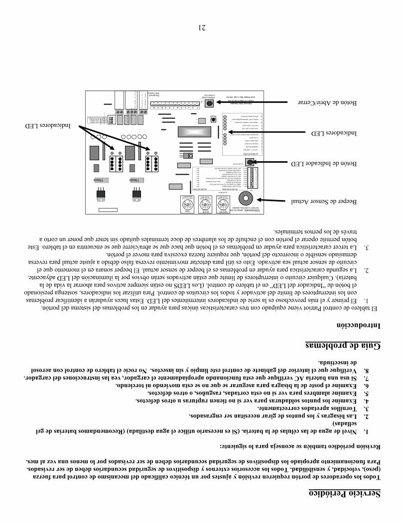
21
Servicio Periódico Todos los operadores de portón requieren revisión y ajustes por un técnico calificado del mecanismo de control para fuerza (peso), velocidad, y sensibilidad. Todos los accesorios externos y dispositivos de seguridad secundarios deben de ser revisados. Para funcionamiento apropiado los dispositivos de seguridad secundarios deben de ser revisados por lo menos una vez al mes. Revisión periódico también se aconseja para lo siguiente:
1. Nivel de agua de las células de la batería. (Si es necesario utilice el agua destilada) (Recomendamos baterías de gel selladas)
2. Las bisagras y los puntos de girar necesitan ser engrasados. 3. Tornillos apretados correctamente. 4. Examine los puntos soldaduras para ver si no tienen rupturas u otros defectos. 5. Examine alambres para ver si no esta cortadas, rasguños, o otros defectos. 6. Examine el poste de la bisagra para asegurar se que no se esta moviendo ni torciendo. 7. Si usa una batería AC verifique que esta funcionando apropiadamente el cargador, vea las instrucciones del cargador. 8. Verifique que el interior del gabinete de control este limpio y sin insectos. No rocíe el tablero de control con aerosol
de insectiuda. Guía de problemas Introducción El tablero de control Patriot viene equipado con tres características únicas para ayudar en los problemas del sistema del portón.
1. El primer y el más provechoso es la serie de indicadores intermitentes del LED. Estas luces ayudarán a identificar problemas con los interruptores de límite del activador y todos los circuitos de control. Para utilizar los indicadores, sostenga presionado el botón de “Indicador del LED” en el tablero de control. (Los LEDS no están siempre activos para ahorrar la vida de la batería). Cualquier circuito o interruptores de límite que están activados serán obvios por la iluminación del LED adyacente.
2. La segunda característica para ayudar en problemas es el beeper de sensor actual. El beeper sonara en el momento que el circuito de sensor actual sea activado. Esto es útil para detectar movimiento reversa falso debido a ajuste actual para reversa demasiado sensible o incorrecto del portón, que requiere fuerza excesiva para mover el portón.
3. La tercer característica para ayudar en problemas es el botón que hace que se abra/cierre que se encuentra en el tablero. Este botón permite operar el portón con el enchufe de los alambres de doce terminales quitado sin tener que poner un corto a través de los pernos terminales.
Beeper de Sensor Actual Botón de Indicador LED Indicadores LED
Indicadores LED Botón de Abrir/Cerrar
Siren Output
OPEN/CLOSECOMMAND
Vehicular Gate Operator
Gate Weight Max. Load: 650 lbs.
LED INDICATORS2
RESET
Entrapment
S E CURI T Y
S HUNT
COMMON GND
MAG LOCK
SOLONOI D LOCK
COMMON GND
OUTPUT+12V
O N 2
34
1SOLONOID LOCK ENABLE MAGNETIC LOCK ENABLE SECURITY SHUNT ENABLE MOTION DETECTOR ENABLE
15
5
010
TIMER TO CLOSE ADJUSTMENT
Timer
ADJUSTMENT
Class I or Class II per UL325
J2 INDICATORS 1- +12V OUT 1.5 AMP MAX 2- COMMON GROUND 3- PUSH BUTTON INPUT 4- OPEN SAFETY EDGE 5- CLOSE INPUT 6- SECONDARY ENTRAPMENT DEVICE INPUT 7- COMMON GROUND 8- STOP CIRCUIT INPUT N/C 9- FREE EXIT / OPEN INPUT 10- UNDER GATE / CENTER LOOP INPUT 11- SAFETY LOOP / REVERSING EDGE INPUT 12- MOTION DETECTOR INPUT
1 2 3 4 5 6 7 8 9101112
J2
BOTH ON FOR DOBLE
DS1 SWITCH SETTINGS FACTORY SETTINGS
SW-1 AUTO CLOSE TIMER ENABLE OFF SW-2 TIMER TO CLOSE WILL ACTIVATE ON LIMIT ONLY ON SW-3 MASTER GATE ENABLE ON SW-4 SLAVE GATE ENABLE OFF SW-5 SOLENOID LOCK OPTION, SEE INSTALLATION MANUAL OFF SW-6 SOFT STOP RETRACT ENABLE OFF SW-7 SOFT STOP EXTEND ENABLE OFF SW-8 STOP CIRCUIT ENABLE OFF SW-9 OPERATING DIRECTION REVERSE OFF SW-10 SOFT START ENABLE FOR SW6 AND SW7 OFF
1 2 3 4 5 6 7 8 9 10
ON
DS1
PATRIOT CONTROL BOARDUSAutomatic MADE IN USA
CURRENT SENSE ADJUSTMENT
010
5
MASTER Sensitivity
CURRENT SENSE ADJUSTMENT
010
5
SLAVE Sensitivity
15
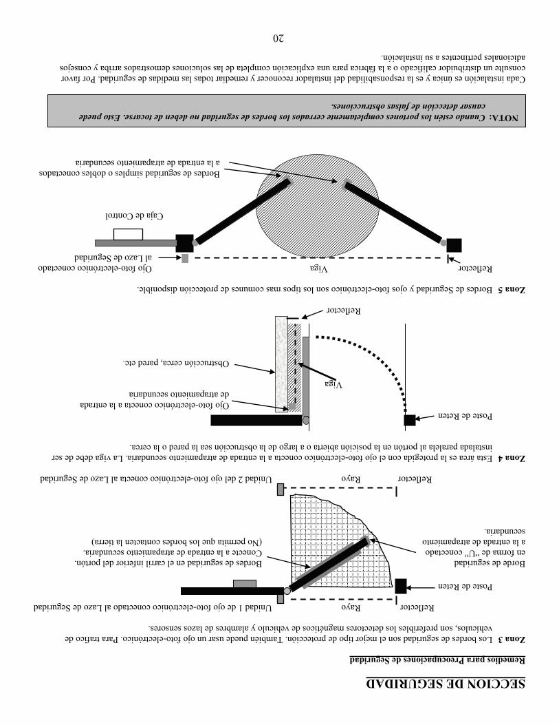
20
SECCION DE SEGURIDAD Remedios para Preocupaciones de Seguridad Zona 3 Los bordes de seguridad son el mejor tipo de protección. También puede usar un ojo foto-electrónico. Para trafico de
vehículos, son preferibles los detectores magnéticos de vehiculo y alambres de lazos sensores. Reflector Rayo Unidad 1 de ojo foto-electrónico conectado al Lazo de Seguridad
Poste de Reten Borde de seguridad Bordes de seguridad en el carril inferior del portón. en forma de “U” conectado Conecte a la entrada de atrapamiento secundaria. a la entrada de atrapamiento (No permita que los bordes contacten la tierra) secundaria. Reflector Rayo Unidad 2 del ojo foto-electrónico conecta al Lazo de Seguridad Zona 4 Esta área es la protegida con el ojo foto-electrónico conecta a la entrada de atrapamiento secundaria. La viga debe de ser
instalada paralela al portón en la posición abierta o a largo de la obstrucción sea la pared o la cerca. Poste de Reten Ojo foto-electrónico conecta a la entrada de atrapamiento secundaria Viga Obstrucción cerca, pared etc. Reflector Zona 5 Bordes de Seguridad y ojos foto-electrónico son los tipos mas comunes de protección disponible. Reflector Viga Ojo foto-electrónico conectado
al Lazo de Seguridad Caja de Control
Bordes de seguridad simples o dobles conectados a la entrada de atrapamiento secundaria
Cada instalación es única y es la responsabilidad del instalador reconocer y remediar todas las medidas de seguridad. Por favor consulte un distribuidor calificado o a la fábrica para una explicación completa de las soluciones demostrados arriba y consejos adicionales pertinentes a su instalación.
NOTA: Cuando estén los portones completamente cerrados los bordes de seguridad no deben de tocarse. Esto puede causar detección de falsas obstrucciones.
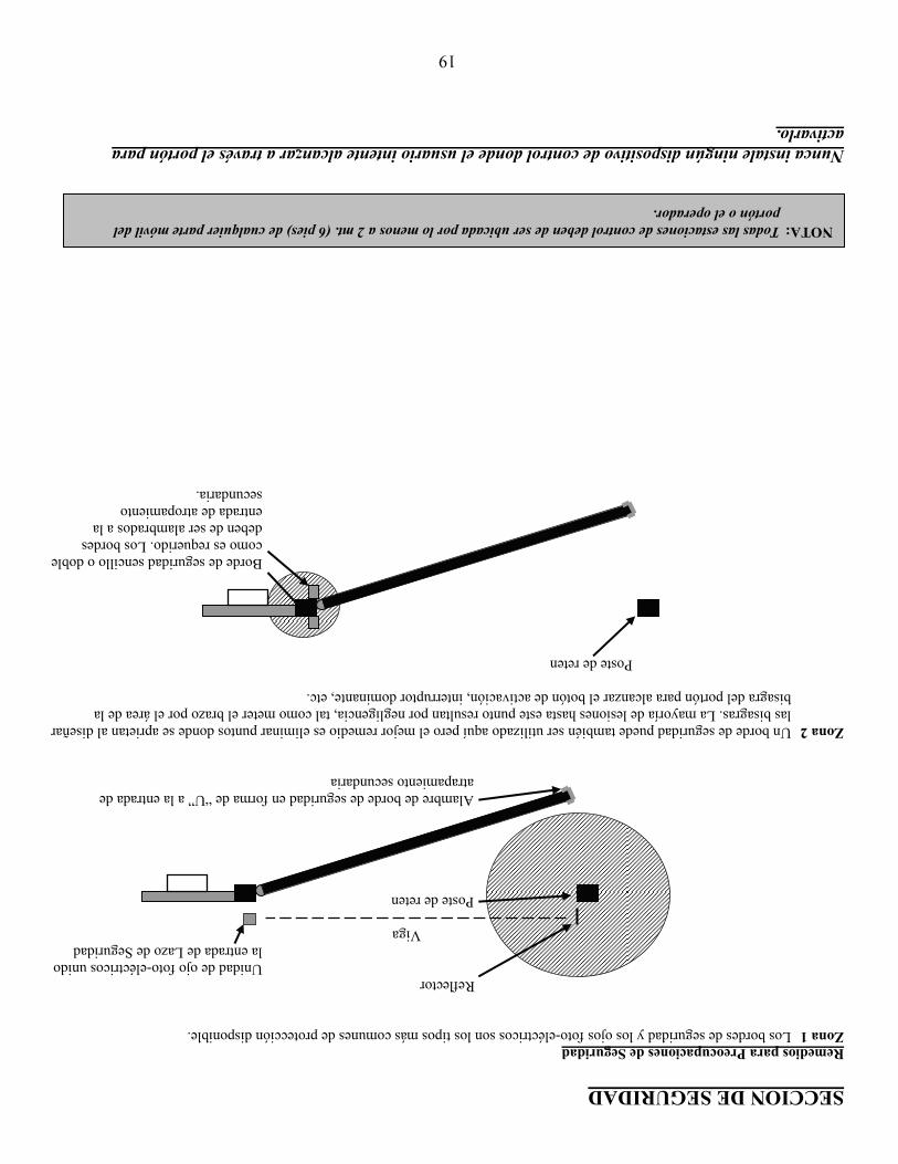
19
SECCION DE SEGURIDAD Remedios para Preocupaciones de Seguridad Zona 1 Los bordes de seguridad y los ojos foto-eléctricos son los tipos más comunes de protección disponible.
Reflector Unidad de ojo foto-eléctricos unido
la entrada de Lazo de Seguridad Viga Poste de reten
Alambre de borde de seguridad en forma de “U” a la entrada de atrapamiento secundaria
Zona 2 Un borde de seguridad puede también ser utilizado aquí pero el mejor remedio es eliminar puntos donde se aprietan al diseñar
las bisagras. La mayoría de lesiones hasta este punto resultan por negligencia, tal como meter el brazo por el área de la bisagra del portón para alcanzar el botón de activación, interruptor dominante, etc.
Poste de reten
Borde de seguridad sencillo o doble como es requerido. Los bordes deben de ser alambrados a la entrada de atropamiento secundaria.
Nunca instale ningún dispositivo de control donde el usuario intente alcanzar a través el portón para activarlo.
NOTA: Todas las estaciones de control deben de ser ubicada por lo menos a 2 mt. (6 pies) de cualquier parte móvil del portón o el operador.
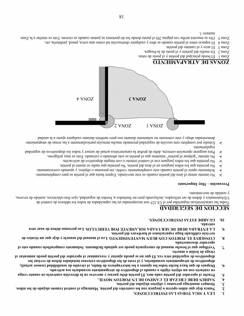
18
1. LEA Y SIGA TODAS LAS INSTRUCCIONES. 2. Nunca deje que niños operen o jueguen con los controles del portón. Mantenga el control remoto alejado de los niños. 3. Siempre mantenga personas y objetos alejados del portón. 4. NADIEN DEBE CRUZAR EL CAMINO DE UN PORTON MOVIL. 5. Pruebe el operador del portón cada mes. El portón debe parase y moverse en la dirección contraria en cuanto venga
en contacto con un objeto rígido o cuando el dispositivo de atrapamiento secundario sea activado. 6. Después de que haya hecho todos los ajustes a los interruptores de límite, el circuito de sensibilidad (sensor actual),
dispositivos de atrapamiento secundarios, y el resto de los dispositivos externos instalados deben de revisar los dispositivos de seguridad otra vez. El que no se pueda ajustar y reexaminar el operador del portón puede aumentar el riesgo de lesión o muerte.
7. Verifique que el broche manual de emergencia puede ser quitado fácilmente. Solamente compruébelo cuando este el operador desconectado.
8. CONSERVE EL PORTON CON BUEN MANTENIMIENTO. Lea el manual del usuario y deje que un técnico de servicio calificado haga reparaciones al hardware del portón.
9. LA ENTRADA DEBE DE SER USADA SOLAMENTE POR VEHICULOS. Las personas deben de usar otra entrada.
10. GUARDE ESTAS INSTRUCCIONES. SECCION DE SEGURIDAD Todas las características requeridas por el UL325 son incorporadas en las capacidades de todos los tableros de control de USAutomatics y deben de ser utilizados, incluyendo pero no limitados a, bordes de seguridad, ojos foto-eléctricos, sentido de reversa, y sentido de movimiento. Precaución – Muy Importante
No intente entrar el área del portón cuando se este moviendo. Espere hasta que el portón se pare completamente. Solamente opere el portón cuando este completamente visible, sin personas o objetos, y ajustado correctamente. No permita que los niños jueguen en el área del portón. No permita que nadie se monte al portón. No permita que los niños jueguen con el control remoto o con ningún dispositivo de activación. No intente “golpear el portón” mientras que el portón se este abriendo o cerrando. Esto es muy peligroso. Para asegurar operación correcta, debe de probar la característica actual de sensor y todos los dispositivos de seguridad
regularmente. Estudie por completo esta sección de seguridad prestando mucha atención particularmente a las zonas de atrapamiento
demostradas abajo y este consiente no solamente durante uso pero también durante cualquier ajuste a la unidad. ZONAS DE ATRAPAMIENTO Zona 1 El borde principal del portón y el poste de reten. Zona 2 En medio del portón y el poste de la bisagra. Zona 3 El arco y el camino del portón. Zona 4 El espacio entre el portón cuando se abre y cualquier obstrucción tal como una cerca, pared, jardinería, etc. Zona 5 (No se muestra arriba vea página 20) el punto donde los do portones se juntan cuando se cierran. Este es similar a la Zona
numero 1.
ZONA 1 ZONA 2 ZONA 3 ZONA 4
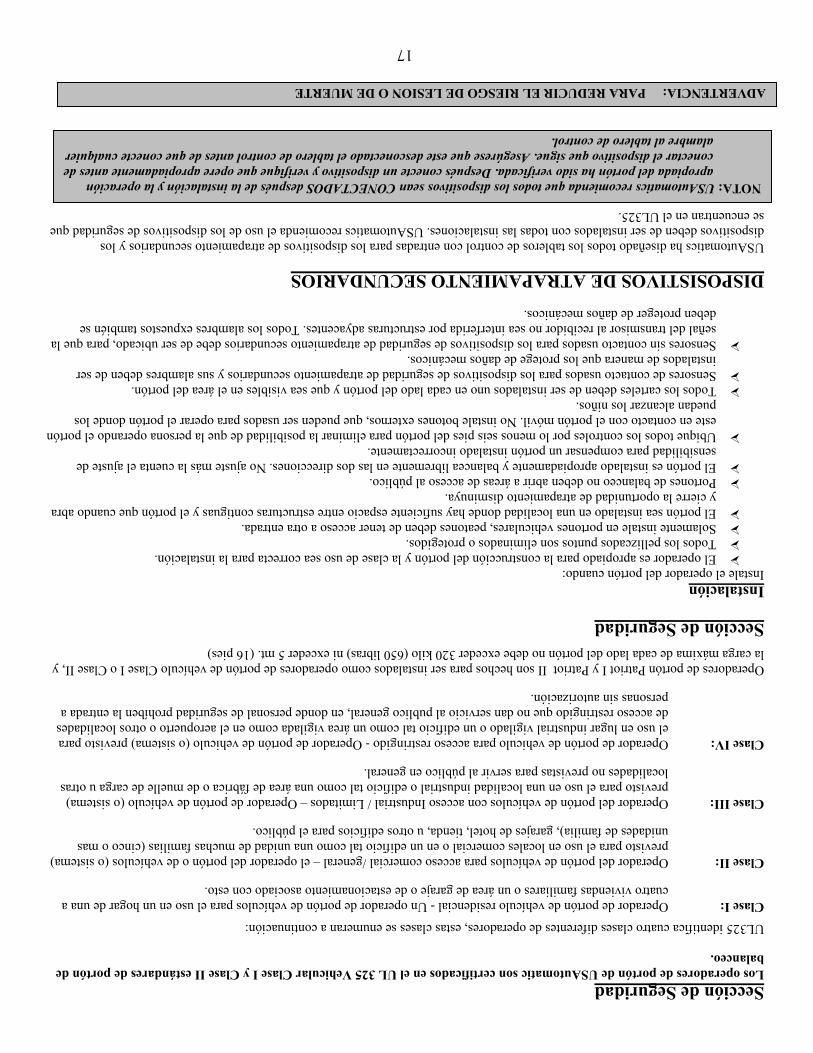
17
Sección de Seguridad Los operadores de portón de USAutomatic son certificados en el UL 325 Vehicular Clase I y Clase II estándares de portón de balanceo. UL325 identifica cuatro clases diferentes de operadores, estas clases se enumeran a continuación:
Clase I: Operador de portón de vehículo residencial - Un operador de portón de vehículos para el uso en un hogar de una a cuatro viviendas familiares o un área de garaje o de estacionamiento asociado con esto.
Clase II: Operador del portón de vehículos para acceso comercial /general – el operador del portón o de vehículos (o sistema) previsto para el uso en locales comercial o en un edificio tal como una unidad de muchas familias (cinco o mas unidades de familia), garajes de hotel, tienda, u otros edificios para el público.
Clase III: Operador del portón de vehículos con acceso Industrial / Limitados – Operador de portón de vehículo (o sistema) previsto para el uso en una localidad industrial o edificio tal como una área de fábrica o de muelle de carga u otras localidades no previstas para servir al público en general.
Clase IV: Operador de portón de vehiculo para acceso restringido - Operador de portón de vehiculo (o sistema) previsto para el uso en lugar industrial vigilado o un edificio tal como un área vigilada como en el aeropuerto o otros localidades de acceso restringido que no dan servicio al publico general, en donde personal de seguridad prohíben la entrada a personas sin autorización.
Operadores de portón Patriot I y Patriot II son hechos para ser instalados como operadores de portón de vehículo Clase I o Clase II, y la carga máxima de cada lado del portón no debe exceder 320 kilo (650 libras) ni exceder 5 mt. (16 pies)
Sección de Seguridad Instalación Instale el operador del portón cuando:
El operador es apropiado para la construcción del portón y la clase de uso sea correcta para la instalación. Todos los pellizcados puntos son eliminados o protegidos. Solamente instale en portones vehiculares, peatones deben de tener acceso a otra entrada. El portón sea instalado en una localidad donde hay suficiente espacio entre estructuras contiguas y el portón que cuando abra
y cierre la oportunidad de atrapamiento disminuya. Portones de balanceo no deben abrir a áreas de acceso al público. El portón es instalado apropiadamente y balancea libremente en las dos direcciones. No ajuste más la cuenta el ajuste de
sensibilidad para compensar un portón instalado incorrectamente. Ubique todos los controles por lo menos seis pies del portón para eliminar la posibilidad de que la persona operando el portón
este en contacto con el portón móvil. No instale botones externos, que pueden ser usados para operar el portón donde los puedan alcanzar los niños.
Todos los carteles deben de ser instalados uno en cada lado del portón y que sea visibles en el área del portón. Sensores de contacto usados para los dispositivos de seguridad de atrapamiento secundarios y sus alambres deben de ser
instalados de manera que los protege de daños mecánicos. Sensores sin contacto usados para los dispositivos de seguridad de atrapamiento secundarios debe de ser ubicado, para que la
señal del transmisor al recibidor no sea interferida por estructuras adyacentes. Todos los alambres expuestos también se deben proteger de daños mecánicos.
DISPOSISTIVOS DE ATRAPAMIENTO SECUNDARIOS USAutomatics ha diseñado todos los tableros de control con entradas para los dispositivos de atrapamiento secundarios y los dispositivos deben de ser instalados con todas las instalaciones. USAutomatics recomienda el uso de los dispositivos de seguridad que se encuentran en el UL325.
NOTA: USAutomatics recomienda que todos los dispositivos sean CONECTADOS después de la instalación y la operación apropiada del portón ha sido verificada. Después conecte un dispositivo y verifique que opere apropiadamente antes de conectar el dispositivo que sigue. Asegúrese que este desconectado el tablero de control antes de que conecte cualquier alambre al tablero de control.
ADVERTENCIA: PARA REDUCIR EL RIESGO DE LESION O DE MUERTE
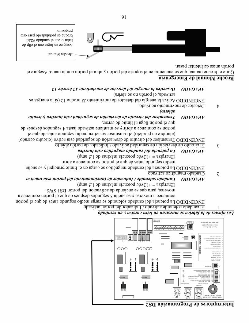
16
Interruptores de Programación DS2 Los ajustes de la fábrica se muestran en letra cursiva y en resaltado 1 El candado solenoide activado / Indicador del portón activado
ENCENDIDO La potencia del candado solenoide se carga medio segundo antes de que el portón comience a moverse y se suelta 3 segundos después de que el portón comience a moverse, para que se encienda de activación del portón DS1 SW5.
(Energiza = +12vdc potencia máxima de 1.5 amp) APAGADO Candado solenoide / Indicador de funcionamiento del portón esta inactivo 2 Candado magnético activado
ENCENDIDO La potencia del candado magnético se carga en el limite principal y se suelta medio segundo antes de que el portón se comience a abrir
(Energiza = +12vdc potencia máxima de 1.5 amp) APAGADO La potencia del candado magnético esta inactiva 3 El circuito de desviación de seguridad activado / Indicador de portón abierto
ENCENDIDO Transmisor del circuito de desviación de seguridad esta activo (circuito cerrado) (alambre en paralelo) el transmisor se activa medio segundo antes de que el portón se comience a abrir y se mantiene activado hasta 4 segundos después de que el portón llega al límite de cerrar.
APAGADO Transmisor del circuito de desviación de seguridad esta inactivo (circuito abierto)
4 Detector de movimiento activado ENCENDIDO Activa la energía del detector de movimiento J2 broche 12 (si la energía es
activada, el portón no se abrirá) APAGADO Desactiva la energía del detector de movimiento J2 broche 12 Broche Manual de Emergencia Quite el broche manual que se encuentra en el soporte del portón y abra el portón con la mano. Asegure el portón antes de intentar pasar. Broche Manual Asegure en lugar con el clip de halar o con el candado #2.El broche es pretaladrado para este propósito.
Siren Output
OPEN/CLOSECOMMAND
Vehicular Gate Operator
Gate Weight Max. Load: 650 lbs.
LED INDICATORS2
RESET
Entrapment
SECURITY
SHUNT
COMMON GND
MAG LOCK
SOLONOI D LOCK
C O MMO N G N D
OU T P U T + 1 2 V
ON 2
34
1SOLONOID LOCK ENABLE MAGNETIC LOCK ENABLE SECURITY SHUNT ENABLE MOTION DETECTOR ENABLE
15
5
010
TIMER TO CLOSE ADJUSTMENT
Timer
ADJUSTMENT
Class I or Class II per UL325
J2 INDICATORS 1- +12V OUT 1.5 AMP MAX 2- COMMON GROUND 3- PUSH BUTTON INPUT 4- OPEN SAFETY EDGE 5- CLOSE INPUT 6- SECONDARY ENTRAPMENT DEVICE INPUT 7- COMMON GROUND 8- STOP CIRCUIT INPUT N/C 9- FREE EXIT / OPEN INPUT 10- UNDER GATE / CENTER LOOP INPUT 11- SAFETY LOOP / REVERSING EDGE INPUT 12- MOTION DETECTOR INPUT
1 2 3 4 5 6 7 8 9 10 11 12
J2
BOTH ON FOR DOBLE
DS1 SWITCH SETTINGS FACTORY SETTINGS
SW-1 AUTO CLOSE TIMER ENABLE OFF SW-2 TIMER TO CLOSE WILL ACTIVATE ON LIMIT ONLY ON SW-3 MASTER GATE ENABLE ON SW-4 SLAVE GATE ENABLE OFF SW-5 SOLENOID LOCK OPTION, SEE INSTALLATION MANUAL OFF SW-6 SOFT STOP RETRACT ENABLE OFF SW-7 SOFT STOP EXTEND ENABLE OFF SW-8 STOP CIRCUIT ENABLE OFF SW-9 OPERATING DIRECTION REVERSE OFF SW-10 SOFT START ENABLE FOR SW6 AND SW7 OFF
1 2 3 4 5 6 7 8 9 10
ON
DS1
PATRIOT CONTROL BOARDUSAutomatic MADE IN USA
CURRENT SENSE ADJUSTMENT
010
5
MASTER Sensitivity
CURRENT SENSE ADJUSTMENT
010
5
SLAVE Sensitivity
15
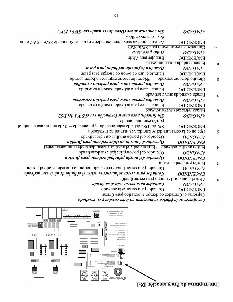
15
Interruptores de Programación DS1 1 Los ajustes de la fábrica se muestran en letra cursiva y en resaltado Capacitar el Contador de tiempo automático para Cerrar ENCENDIDO Contador para cerrar esta activado APAGADO Contador para cerrar está desactivado 2 Abra el contador de tiempo para cerrar función ENCENDIDO Contador para cerrar solamente se activa si el limite de abrir esta activado APAGADO Contador para cerrar funciona de cualquier punto que este parado el portón 3 Portón principal activado ENCENDIDO Operador del portón principal activado para función APAGADO Operador del portón principal esta desactivado 4 Portón auxiliar activado (El principal y el auxiliar encendidos doble simultáneamente) ENCENDIDO Operador del portón auxiliar activado para función APAGADO Operador del portón auxiliar esta desactivado 5 Opción de la cerradura del solenoide, vea manual de Instalación
ENCENDIDO SW del DS2 debe de estar encendido, potencia de +12vdc con retraso cuando el portón este funcionando
APAGADO Sin función, para mas información vea el SW 1 del DS2 6 Parada retractada suave activado ENCENDIDO Parada suave para activada posición retractada APAGADO Desactiva parada suave para posición retractada 7 Parada extendida suave activado ENCENDIDO Parada suave para activada posición extendida APAGADO Desactiva parada suave para posición extendida 8 Circuito de parar activado *Normalmente se requiere un botón cerrado ENCENDIDO Permite el uso de botón de energía para parar APAGADO Desactiva la función del botón para parar 9 Funcionando la dirección reversa ENCENDIDO Empujar para Abrir APAGADO Halar para Abrir 10 Comienzo suave activado para SW6, SW7
ENCENDIDO Active comienzo suave para extender y retractar, Solamente SW6 o SW7 o los dos estén encendidos
APAGADO Sin comienzo suave (Debe de ser usado con SW6 y SW7)
Siren Output
OPEN/CLOSECOMMAND
Vehicular Gate Operator
Gate Weight Max. Load: 650 lbs.
LED INDICATORS2
RESET
Entrapment
SECURITY
SHUNT
C O MMO N G N D
MA G LO C K
S O L O N O I D LO C K
C O MMO N G N D
OU T P U T + 1 2 V
ON 2
34
1SOLONOID LOCK ENABLE MAGNETIC LOCK ENABLE SECURITY SHUNT ENABLE MOTION DETECTOR ENABLE
15
5
010
TIMER TO CLOSE ADJUSTMENT
Timer
ADJUSTMENT
Class I or Class II per UL325
J2 INDICATORS 1- +12V OUT 1.5 AMP MAX 2- COMMON GROUND 3- PUSH BUTTON INPUT 4- OPEN SAFETY EDGE 5- CLOSE INPUT 6- SECONDARY ENTRAPMENT DEVICE INPUT 7- COMMON GROUND 8- STOP CIRCUIT INPUT N/C 9- FREE EXIT / OPEN INPUT 10- UNDER GATE / CENTER LOOP INPUT 11- SAFETY LOOP / REVERSING EDGE INPUT 12- MOTION DETECTOR INPUT
1 2 3 4 5 6 7 8 91011 12
J2
BOTH ON FOR DOBLE
DS1 SWITCH SETTINGS FACTORY SETTINGS
SW-1 AUTO CLOSE TIMER ENABLE OFF SW-2 TIMER TO CLOSE WILL ACTIVATE ON LIMIT ONLY ON SW-3 MASTER GATE ENABLE ON SW-4 SLAVE GATE ENABLE OFF SW-5 SOLENOID LOCK OPTION, SEE INSTALLATION MANUAL OFF SW-6 SOFT STOP RETRACT ENABLE OFF SW-7 SOFT STOP EXTEND ENABLE OFF SW-8 STOP CIRCUIT ENABLE OFF SW-9 OPERATING DIRECTION REVERSE OFF SW-10 SOFT START ENABLE FOR SW6 AND SW7 OFF
1 2 3 4 5 6 7 8 9 10
ON
DS1
PATRIOT CONTROL BOARDUSAutomatic MADE IN USA
CURRENT SENSE ADJUSTMENT
010
5
MASTER Sensitivity
CURRENT SENSE ADJUSTMENT
010
5
SLAVE Sensitivity
15
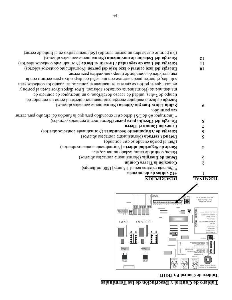
14
Tablero de Control y Descripción de las Terminales Tablero de Control PATRIOT TERMINAL DESCRIPCION
1 +12 voltios dc de potencia * Potencia máxima actual 1.5 amp (1500 milliamps) 2 Conexión la Tierra Común 3 Botón de Energía. (Normalmente contactos abiertos) Botón, control de radio, teclado numérico, etc. 4 Borde de Seguridad abierta (Normalmente contactos abiertos) (Para el portón cuando se esta abriendo) 5 Potencia cerrada (Normalmente contactos abiertos) 6 Energía de Atrapamiento Secundaria (Normalmente contactos abiertos) 7 Conexión Común el Tierra 8 Energía del Circuito para parar (Normalmente contactos cerrados)
* Interruptor #8 de DS1 debe estar encendido para que la función del circuito para cerrar sea permitido.
9 Salida Libre/ Energía Abierta (Normalmente contactos abiertos) Energía de lazo o cualquier energía para mantener abierto tal como un contador de tiempo de 7-días, unidad de acceso de teléfono, o un interruptor de contacto de mantenimiento (Normalmente contactos abiertos). Estos dispositivos abren el portón y evitarán que el portón se cierre si se mantiene el contacto. En cuanto los contactos sean soltados, el portón puede cerrarse con una señal del dispositivo para cerrar o con la característica de contador de tiempo automática para cerrar.
10 Energía del lazo central o lazo bajo del portón (Normalmente contactos abiertos) 11 Energía del Lazo de seguridad / Invertir el Borde (Normalmente contactos abiertos) 12 Energía del Detector de movimiento (Normalmente contactos abiertos) (No permite que se abra un portón cerrado) (Solamente activo en el limite de cerrar)
Siren Output
OPEN/CLOSE COMMAND
Vehicular Gate Operator
Gate Weight Max. Load: 650 lbs.
LED INDICATORS2
RESET
Entrapment
SECURITY
SHUNT
C O MMO N G N D
MA G LO C K
S O L O N O I D LO C K C
O MMO N G N D
OU T P U T + 1 2 V
O N 2
34
1SOLONOID LOCK ENABLE MAGNETIC LOCK ENABLE SECURITY SHUNT ENABLE MOTION DETECTOR ENABLE
15
5
010
TIMER TO CLOSE ADJUSTMENT
Timer
ADJUSTMENT
Class I or Class II per UL325
J2 INDICATORS 1- +12V OUT 1.5 AMP MAX 2- COMMON GROUND 3- PUSH BUTTON INPUT 4- OPEN SAFETY EDGE 5- CLOSE INPUT 6- SECONDARY ENTRAPMENT DEVICE INPUT 7- COMMON GROUND 8- STOP CIRCUIT INPUT N/C 9- FREE EXIT / OPEN INPUT 10- UNDER GATE / CENTER LOOP INPUT 11- SAFETY LOOP / REVERSING EDGE INPUT 12- MOTION DETECTOR INPUT
1 2 3 4 5 6 7 8 9 10 11 12
J2
BOTH ON FOR DOBLE
DS1 SWITCH SETTINGS FACTORY SETTINGS
SW-1 AUTO CLOSE TIMER ENABLE OFF SW-2 TIMER TO CLOSE WILL ACTIVATE ON LIMIT ONLY ON SW-3 MASTER GATE ENABLE ON SW-4 SLAVE GATE ENABLE OFF SW-5 SOLENOID LOCK OPTION, SEE INSTALLATION MANUAL OFF SW-6 SOFT STOP RETRACT ENABLE OFF SW-7 SOFT STOP EXTEND ENABLE OFF SW-8 STOP CIRCUIT ENABLE OFF SW-9 OPERATING DIRECTION REVERSE OFF SW-10 SOFT START ENABLE FOR SW6 AND SW7 OFF
1 2 3 4 5 6 7 8 9 10
ON
DS1
PATRIOT CONTROL BOARDUSAutomatic MADE IN USA
CURRENT SENSE ADJUSTMENT
010
5
MASTER Sensitivity
CURRENT SENSE ADJUSTMENT
010
5
SLAVE Sensitivity
15
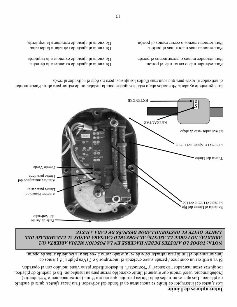
13
Interruptores de Límite Los ajustes del interruptor de límite se encuentran en el fondo del activador. Para hacer ajustes, quite el enchufe de plástico. Los ajustes normales de la fábrica permiten que recorra ½ mt. (aproximadamente 70% abierto.) Probablemente, usted tendrá que ajustar el límite extendido cerrar para su instalación. En el enchufe de plástico, los ajustes están marcados “Extender” y “Retractar”. El destornillador plano viene incluido con el operador.
Si va a utilizar un comienzo / parada suave encienda el interruptor 6 o 7 (Vea página 15.) Antes de funcionamiento el limité para retractar debe de ser ajustado como 5 vueltas a la izquierda antes de operar.
Parte de Arriba del Activador
Extienda el Limite del Eje Retracte el Limite del Eje Alambre blanco del Límite para cerrar Alambre anaranjado del Límite para abrir Común Verde Tuerca del Límite Ranuras De Ajuste Del Límite El Activador visto de abajo RETRACTAR EXTENDER Lo siguiente le ayudará. Mostrados abajo estar los ajustes para la instalación de estirar para abrir. Puede montar el activador al revés para que sean más fáciles los ajustes, pero no deje el activador al revés. Para extender más o cerrar más el portón. De vuelta al ajuste de extender a la derecha. Para extender menos o cerrar menos el portón. De vuelta al ajuste de extender a la izquierda. Para retractar más o abrir más el portón. De vuelta al ajuste de retractar a la derecha. Para retractar menos o cerrar menos el portón. De vuelta al ajuste de retractar a la izquierda.
NOTA: TODOS LO AJUSTES DEBEN HACERSE EN LA POSCION MEDIA ABIERTA (1/2 ABIERTA). NO FORCE EL AJUSTE; AL FORZARLO CAUSARA DAÑOS AL ENSAMBLAJE DEL LIMITE. QUITE EL DESTORNILLADOR DESPUÉS DE CADA AJUSTE.
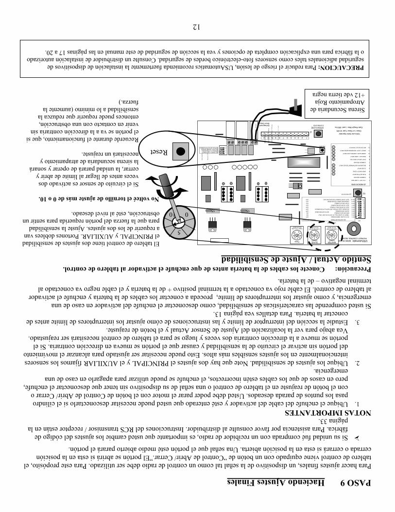
12
PASO 9 Haciendo Ajustes Finales Para hacer ajustes finales, un dispositivo de la señal tal como un control de radio debe ser utilizado. Para este propósito, el tablero de control viene equipado con un botón de “Control de Abrir/ Cerrar.”El portón se abrirá si esta en la posición cerrada o cerrará si esta en la posición abierta. Una señal que el portón esté medio abierto parará el portón.
Si su unidad fué comprada con un recibidor de radio, es importante que usted cambie los ajustes del código de fábrica. Para asistencia por favor consulte al distribuidor. Instrucciones del RCS transmisor / receptor están en la página 33.
NOTAS IMPORTANTES 1. Ubique el enchufe del cable del activador y esté enterado que usted puede necesitar desconectarlo si el cilindro
pasa los puntos de parada deseados. Usted debe poder parar el motor con el botón de Control de Abrir/ Cerrar o con el botón de reajuste en el tablero de control o una señal de su dispositivo sin tener que desconectar el enchufe, pero en casos de que los cables estén incorrectos, el enchufe se puede utilizar para apagarlo en caso de una emergencia.
2. Ubique los ajustes de sensibilidad. Note que hay dos ajustes el PRINCIPAL y el AUXILIAR fijamos los sensores intencionalmente en los ajustes sensibles más altos. Esto puede necesitar ser ajustado para alcanzar el movimiento del portón sin activar el circuito de la sensibilidad y causar que el portón se mueva en dirección contraria. Si el portón se mueve a la dirección contraria dos veces y luego se para el tablero de control necesitará ser reajustado. Vea abajo para ver la localización del Ajuste de Sensor Actual y el botón de reajuste.
3. Estudie la sección del interruptor de límite y las instrucciones de cómo ajustar los interruptores de límite antes de conectar la batería. Para detalles vea página 13.
Si usted comprende las características de sensibilidad, como desconectar el enchufe del activador en caso de una emergencia, y como ajustar los interruptores de límite, proceda a conectar los cables de la batería y enchufe el activador al tablero de control. El cable rojo va conectado a la terminal positivo + de la batería y el cable negro va conectado al terminal negativo – de la batería.
Precaución: Conecte los cables de la batería antes de que enchufe el activador al tablero de control. Sentido Actual / Ajuste de Sensibilidad
El tablero de control tiene dos ajustes de sensibilidad el PRINCIPAL y AUXILIAR. Portones doblees van a requerir de los dos ajustes. Ajuste la sensibilidad para que la fuerza del portón requerida para sentir un obstrucción, esté al nivel deseado.
No volteé el tornillo de ajuste más de 0 o 10.
Si el circuito de sensor es activado dos veces antes de llegar al límite de abrir y cerrar, la unidad parará de operar y sonará la sirena secundaria de atrapamiento y necesitará un reajuste. Recuerde durante el funcionamiento, que si
el portón se va a la dirección contraria sin venir en contacto con una obstrucción, entonces puede requerir que reduzca la
Sirena Secundaria de sensibilidad a lo mínimo (aumente la Atropamiento Roja fuerza.) +12 vde tierra negra
PRECAUCION: Para reducir el riesgo de lesión, USAutomatics recomienda fuertemente la instalación de dispositivos de seguridad adicionales tales como sensores foto-electrónico bordes de seguridad. Consulte un distribuidor de instalación autorizado o la fábrica para una explicación completa de opciones y vea la sección de seguridad de este manual en las páginas 17 a 20.
Siren Output
OPEN/CLOSE COMMAND
Vehicular Gate Operator
Gate Weight Max. Load: 650 lbs.
LED INDICATORS2
RESET
Entrapment
SECURITY
SHUNT
C O MMO N G N D
MA G LO C K
S O L O N O I D LO C K
C O MMO N G N D
OU T P U T + 1 2 V
O N 2
34
1SOLONOID LOCK ENABLE MAGNETIC LOCK ENABLE SECURITY SHUNT ENABLE MOTION DETECTOR ENABLE
15
5
010
TIMER TO CLOSE ADJUSTMENT
Timer
ADJUSTMENT
Class I or Class II per UL325
J2 INDICATORS 1- +12V OUT 1.5 AMP MAX 2- COMMON GROUND 3- PUSH BUTTON INPUT 4- OPEN SAFETY EDGE 5- CLOSE INPUT 6- SECONDARY ENTRAPMENT DEVICE INPUT 7- COMMON GROUND 8- STOP CIRCUIT INPUT N/C 9- FREE EXIT / OPEN INPUT 10- UNDER GATE / CENTER LOOP INPUT 11- SAFETY LOOP / REVERSING EDGE INPUT 12- MOTION DETECTOR INPUT
1 2 3 4 5 6 7 8 9 10 11 12
J2
BOTH ON FOR DOBLE
DS1 SWITCH SETTINGS FACTORY SETTINGS
SW-1 AUTO CLOSE TIMER ENABLE OFF SW-2 TIMER TO CLOSE WILL ACTIVATE ON LIMIT ONLY ON SW-3 MASTER GATE ENABLE ON SW-4 SLAVE GATE ENABLE OFF SW-5 SOLENOID LOCK OPTION, SEE INSTALLATION MANUAL OFF SW-6 SOFT STOP RETRACT ENABLE OFF SW-7 SOFT STOP EXTEND ENABLE OFF SW-8 STOP CIRCUIT ENABLE OFF SW-9 OPERATING DIRECTION REVERSE OFF SW-10 SOFT START ENABLE FOR SW6 AND SW7 OFF
1 2 3 4 5 6 7 8 9 10
ON
DS1
PATRIOT CONTROL BOARDUSAutomatic MADE IN USA
CURRENT SENSE ADJUSTMENT
010
5
MASTER Sensitivity
CURRENT SENSE ADJUSTMENT
010
5
SLAVE Sensitivity
1510 0
5
Reset
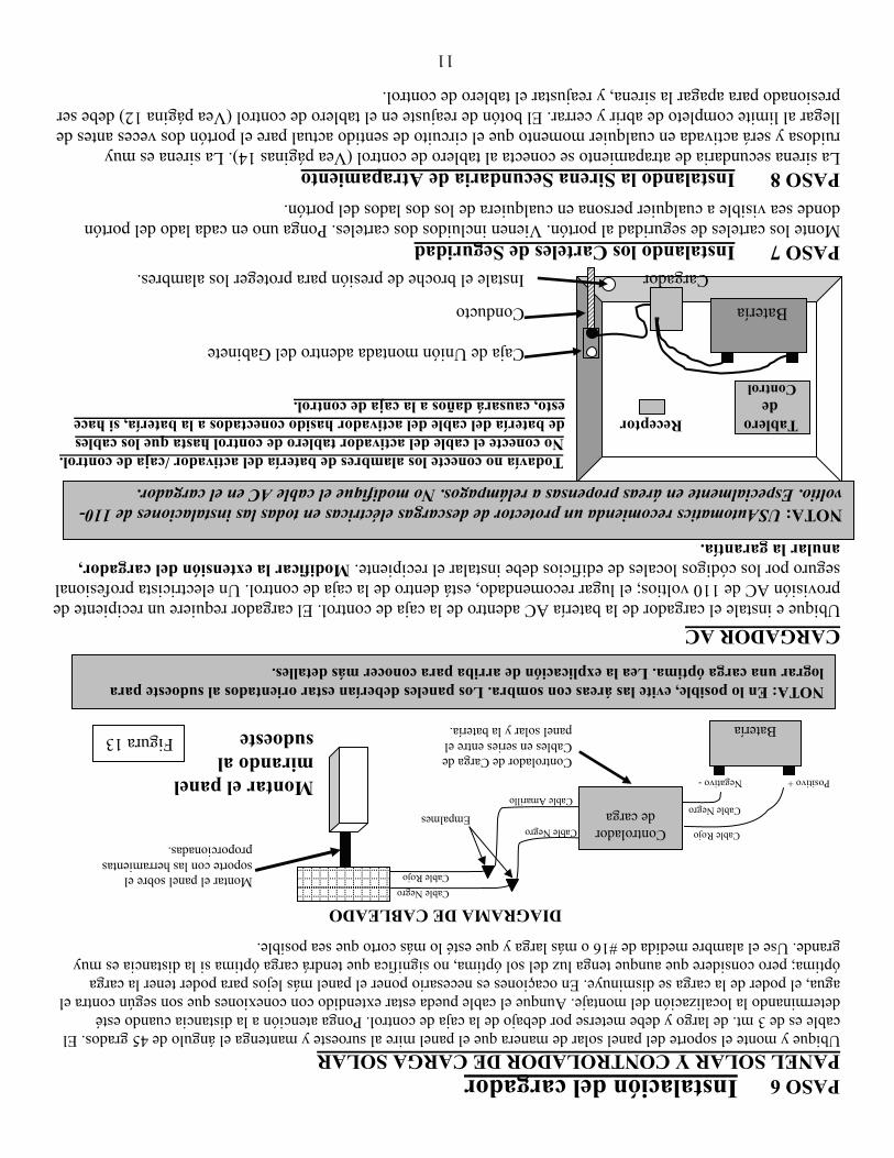
11
PASO 6 Instalación del cargador
PANEL SOLAR Y CONTROLADOR DE CARGA SOLAR Ubique y monte el soporte del panel solar de manera que el panel mire al suroeste y mantenga el ángulo de 45 grados. El cable es de 3 mt. de largo y debe meterse por debajo de la caja de control. Ponga atención a la distancia cuando esté determinando la localización del montaje. Aunque el cable pueda estar extendido con conexiones que son según contra el agua, el poder de la carga se disminuye. En ocaçiones es necesario poner el panel más lejos para poder tener la carga óptima; pero considere que aunque tenga luz del sol óptima, no significa que tendrá carga óptima si la distancia es muy grande. Use el alambre medida de #16 o más larga y que esté lo más corto que sea posible.
DIAGRAMA DE CABLEADO
Montar el panel mirando al
sudoeste CARGADOR AC Ubique e instale el cargador de la batería AC adentro de la caja de control. El cargador requiere un recipiente de provisión AC de 110 voltios; el lugar recomendado, está dentro de la caja de control. Un electricista profesional seguro por los códigos locales de edificios debe instalar el recipiente. Modificar la extensión del cargador, anular la garantía.
Todavía no conecte los alambres de batería del activador /caja de control. No conecte el cable del activador tablero de control hasta que los cables
Tablero Receptor de batería del cable del activador hasido conectados a la batería, si hace de esto, causará daños a la caja de control.
Control Caja de Unión montada adentro del Gabinete
Batería Conducto
Cargador Instale el broche de presión para proteger los alambres.
PASO 7 Instalando los Carteles de Seguridad Monte los carteles de seguridad al portón. Vienen incluidos dos carteles. Ponga uno en cada lado del portón donde sea visible a cualquier persona en cualquiera de los dos lados del portón.
PASO 8 Instalando la Sirena Secundaria de Atrapamiento La sirena secundaria de atrapamiento se conecta al tablero de control (Vea páginas 14). La sirena es muy ruidosa y será activada en cualquier momento que el circuito de sentido actual pare el portón dos veces antes de llegar al limite completo de abrir y cerrar. El botón de reajuste en el tablero de control (Vea página 12) debe ser presionado para apagar la sirena, y reajustar el tablero de control.
NOTA: En lo posible, evite las áreas con sombra. Los paneles deberían estar orientados al sudoeste para lograr una carga óptima. Lea la explicación de arriba para conocer más detalles.
NOTA: USAutomatics recomienda un protector de descargas eléctricas en todas las instalaciones de 110-voltio. Especialmente en áreas propensas a relámpagos. No modifique el cable AC en el cargador.
Montar el panel sobre el soporte con las herramientas proporcionadas.
Figura 13
Cable Amarillo
Positivo + Negativo -
Batería
Cable Rojo
Cable Negro
Controlador de Carga de Cables en series entre el panel solar y la batería.
Cable Negro
Cable Rojo Cable Negro
Controlador de carga Empalmes
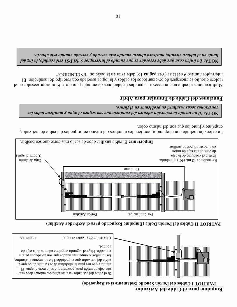
10
Empalme para el Cable del Activador PARTIOT I Cables del Portón Sencillo (Solamente si es Requerido)
Si el cable del activador va a ser añadido, entones debe usar una caja de unión para, prevenir que se le meta el agua. El alambre que use para la añadidura debe ser más chico que el cable del activador que va incluido. Use solamente el alambre, los tornillos, o empalmes rizados que son aprobados para la conexión. Haga el segundo empalme adentro de la caja de control.
Caja de Unión (Contra el agua) Figura 7A
PATRIOT II Cables del Portón Doble (Empalme Requerido para el Activador Auxiliar)
Portón Principal Portón Auxiliar Conducto Extensión de 12 mt. (40’) si incluida. Caja de Unión Instale el conducto de la caja (Contra el agua) de control a la caja de unión en el poste del portón auxiliar. Importante: El cable auxiliar debe de ser lo mas corto que sea posible. La extensión incluida con el operador, contiene los alambres del mismo color que los del cable del activador, empalme y junte los que son del mismo color. Funciones del Cable de Empujar para Abrir
Modificaciones al cable no son necesarias para las instalaciones de empujar para abrir. El microprocesador en el tablero circuito se encargará de reversar todos los cables y la lógica asociada con este tipo de instalación. El interruptor numero 9 del DS1 (Vea página 15) debe estar en la posición “ENCENDIDO.”
NOTA: Si no instala la extensión adentro del conducto que sea seguro el agua y mantiene todas las conexiones secas resultará en problemas en el futuro.
NOTA: La única cosa que debe recordar es que cuando el interruptor 9 del DS1 esté rendido, la luz del límite en el tablero circuito, mostrará abierto cuando esté cerrado y cerrado cuando esté abierto.
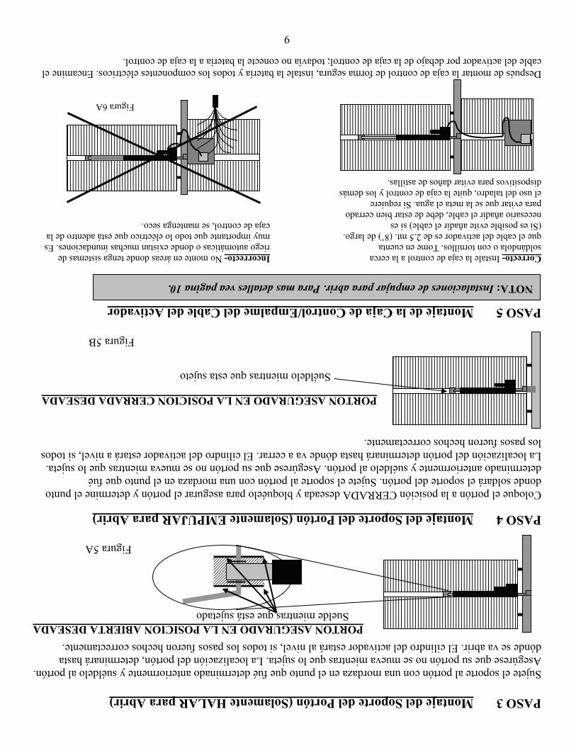
9
PASO 3 Montaje del Soporte del Portón (Solamente HALAR para Abrir) Sujete el soporte al portón con una mordaza en el punto que fué determinado anteriormente y suéldelo al portón. Asegúrese que su portón no se mueva mientras que lo sujeta. La localización del portón, determinará hasta dónde se va abrir. El cilindro del activador estará al nivel, si todos los pasos fueron hechos correctamente.
PORTON ASEGURADO EN LA POSICION ABIERTA DESEADA Suelde mientras que está sujetado
Figura 5A
PASO 4 Montaje del Soporte del Portón (Solamente EMPUJAR para Abrir) Coloque el portón a la posición CERRADA deseada y bloquéelo para asegurar el portón y determine el punto donde soldará el soporte del portón. Sujete el soporte al portón con una mordaza en el punto que fué determinado anteriormente y suéldelo al portón. Asegúrese que su portón no se mueva mientras que lo sujeta. La localización del portón determinará hasta dónde va a cerrar. El cilindro del activador estará a nivel, si todos los pasos fueron hechos correctamente.
PORTON ASEGURADO EN LA POSICION CERRADA DESEADA
Suéldelo mientras que esta sujeto
Figura 5B PASO 5 Montaje de la Caja de Control/Empalme del Cable del Activador Correcto- Instale la caja de control a la cerca Incorrecto- No monte en áreas donde tenga sistemas de soldándola o con tornillos. Tome en cuenta riego automáticas o donde existan muchas inundaciones. Es que el cable del activador es de 2.5 mt. (8’) de largo. muy importante que todo lo eléctrico que está adentro de la (Si es posible evite añadir el cable) si es caja de control, se mantenga seco. necesario añadir el cable, debe de estar bien cerrado para evitar que se la meta el agua. Si requiere el uso del taladro, quite la caja de control y los demás dispositivos para evitar daños de astillas. Figura 6A Después de montar la caja de control de forma segura, instale la batería y todos los componentes eléctricos. Encamine el cable del activador por debajo de la caja de control; todavía no conecte la batería a la caja de control.
NOTA: Instalaciones de empujar para abrir. Para mas detalles vea pagina 10.
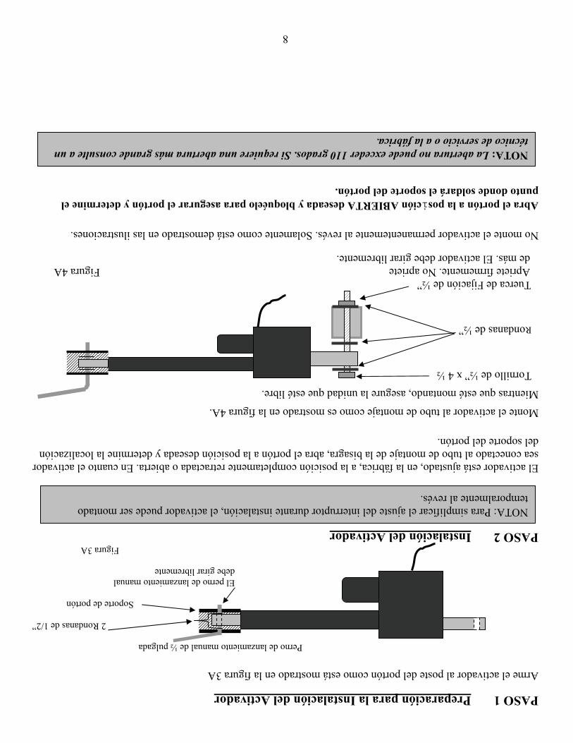
8
PASO 1 Preparación para la Instalación del Activador Arme el activador al poste del portón como está mostrado en la figura 3A Perno de lanzamiento manual de ½ pulgada
2 Rondanas de 1/2”
Soporte de portón
El perno de lanzamiento manual debe girar libremente
Figura 3A
PASO 2 Instalación del Activador
El activador está ajustado, en la fábrica, a la posición completamente retractada o abierta. En cuanto el activador sea conectado al tubo de montaje de la bisagra, abra el portón a la posición deseada y determine la localización del soporte del portón. Monte el activador al tubo de montaje como es mostrado en la figura 4A.
Mientras que esté montando, asegure la unidad que esté libre.
Tornillo de ½” x 4 ½ Rondanas de ½” Tuerca de Fijación de ½” Apriete firmemente. No apriete Figura 4A de más. El activador debe girar libremente. No monte el activador permanentemente al revés. Solamente como está demostrado en las ilustraciones. Abra el portón a la posición ABIERTA deseada y bloquéelo para asegurar el portón y determine el punto donde soldará el soporte del portón.
NOTA: Para simplificar el ajuste del interruptor durante instalación, el activador puede ser montado temporalmente al revés.
NOTA: La abertura no puede exceder 110 grados. Si requiere una abertura más grande consulte a un técnico de servicio o a la fábrica.
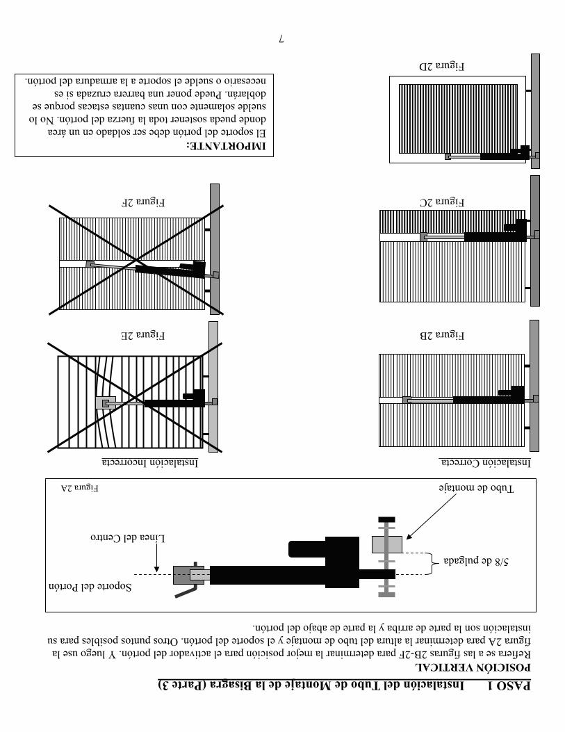
7
PASO 1 Instalación del Tubo de Montaje de la Bisagra (Parte 3) POSICIÓN VERTICAL Refiera se a las figuras 2B-2F para determinar la mejor posición para el activador del portón. Y luego use la figura 2A para determinar la altura del tubo de montaje y el soporte del portón. Otros puntos posibles para su instalación son la parte de arriba y la parte de abajo del portón.
Soporte del Portón 5/8 de pulgada Línea del Centro Tubo de montaje Figura 2A Instalación Correcta Instalación Incorrecta
Figura 2B Figura 2E
Figura 2C Figura 2F
Figura 2D
IMPORTANTE: El soporte del portón debe ser soldado en un área donde pueda sostener toda la fuerza del portón. No lo suelde solamente con unas cuantas estacas porque se doblarán. Puede poner una barrera cruzada si es necesario o suelde el soporte a la armadura del portón.
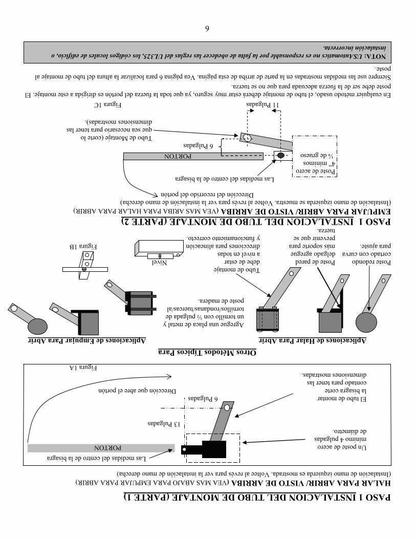
6
PASO 1 INSTALACION DEL TUBO DE MONTAJE (PARTE 1) HALAR PARA ABRIR/ VISTO DE ARRIBA (VEA MAS ABAJO PARA EMPUJAR PARA ABRIR) (Instalación de mano izquierda es mostrada. Voltee al revés para ver la instalación de mano derecha) Las medidas del centro de la bisagra
Un poste de acero PORTON mínimo 4 pulgadas de diámetro. 13 Pulgadas
El tubo de montar 6 Pulgadas la bisagra corte Dirección que abre el portón
contado para tener las dimensiones mostradas. Figura 1A
Otros Métodos Típicos Para
Aplicaciones de Halar Para Abrir Aplicaciones de Empujar Para Abrir Agregue una placa de metal y
un tornillo con ½ pulgada de tornillos/rondanas/tuercas/al poste de madera.
Tubo de montaje Poste redondo Poste de pared debe de estar Nivel cortado con curva delgado agregue a nivel en todas para ajuste. más soporte para direcciones para alineación Figura 1B prevenir que se y funcionamiento correcto. tuerza. PASO 1 INSTALACION DEL TUBO DE MONTAJE (PARTE 2) EMPUJAR PARA ABRIR/ VISTO DE ARRIBA (VEA MAS ARIBA PARA HALAR PARA ABRIR) (Instalación de mano izquierda se muestra. Voltee al revés para ver la instalación de mano derecha)
Dirección del recorrido del portón
Las medidas del centro de la bisagra Poste de acero 4” mínimos ¼ de grueso PORTON
6 Pulgadas Tubo de Montaje (corte lo que sea necesario para tener las dimensiones mostradas).
11 Pulgadas Figura 1C En cualquier método usado, el tubo de montaje deberá estar muy seguro, ya que toda la fuerza del portón es dirigida a este montaje. El poste debe ser de la fuerza adecuada para que no se tuerza. Siempre use las medidas mostradas en la parte de arriba de esta página. Vea página 6 para localizar la altura del tubo de montaje al poste. NOTA: USAutomatics no es responsable por la falta de obedecer las reglas del UL325, los códigos locales de edificio, o
instalación incorrecta.
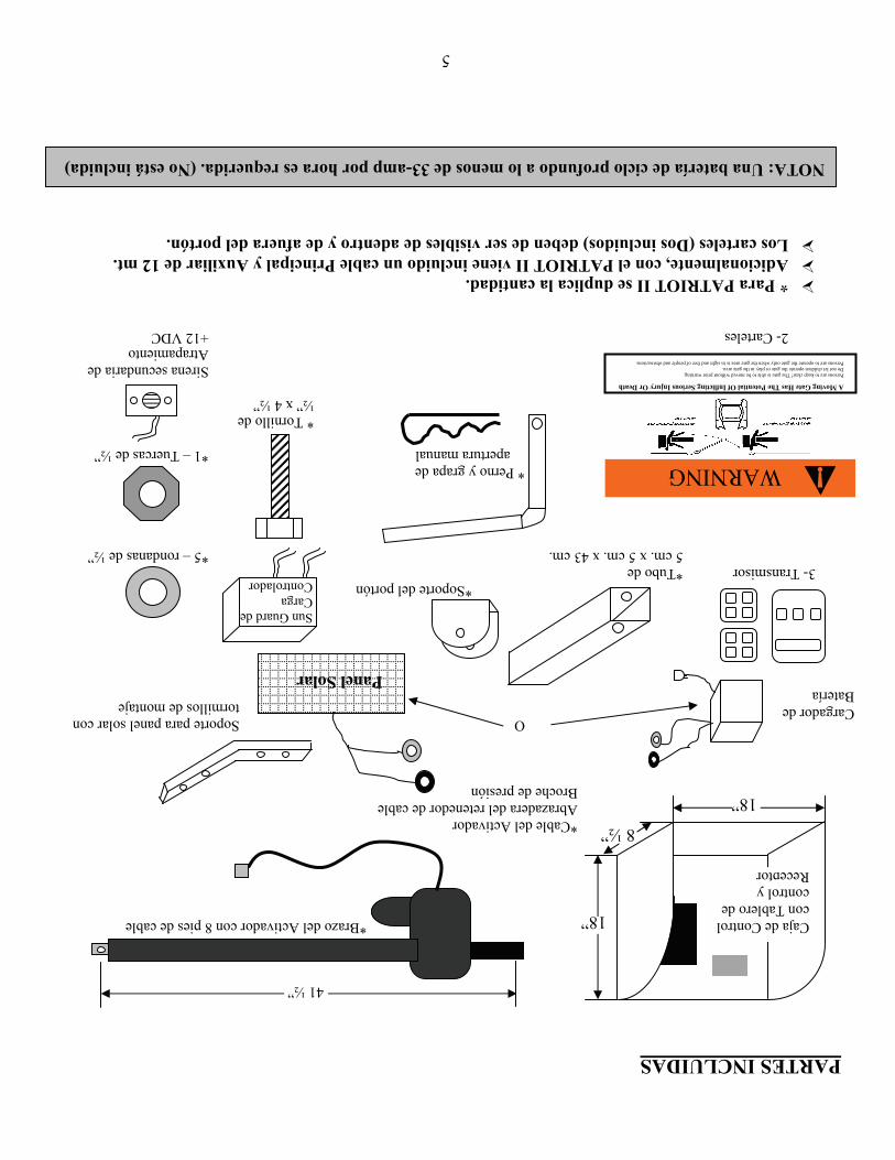
5
PARTES INCLUIDAS
*Brazo del Activador con 8 pies de cable *Cable del Activador Abrazadera del retenedor de cable Broche de presión O Soporte para panel solar con tormillos de montaje *Soporte del portón 3- Transmisor *Tubo de 5 cm. x 5 cm. x 43 cm. *5 – rondanas de ½” * Perno y grapa de apertura manual *1 – Tuercas de ½” * Tornillo de ½” x 4 ½” Sirena secundaria de Atrapamiento 2- Carteles +12 VDC
* Para PATRIOT II se duplica la cantidad. Adicionalmente, con el PATRIOT II viene incluido un cable Principal y Auxiliar de 12 mt. Los carteles (Dos incluidos) deben de ser visibles de adentro y de afuera del portón.
NOTA: Una batería de ciclo profundo a lo menos de 33-amp por hora es requerida. (No está incluida)
WARNING
A Moving Gate Has The Potential Of Inflicting Serious Injury Or Death Persons are to keep clear! The gate is able to be moved without prior warning. Do not let children operate the gate or play in the gate area. Persons are to operate the gate only when the gate area is in sight and free of people and obstructions.
Cargador de Batería
Panel Solar
41 ½”
8 ½”
18”
18”
Caja de Control con Tablero de control y Receptor
Sun Guard de Carga Controlador
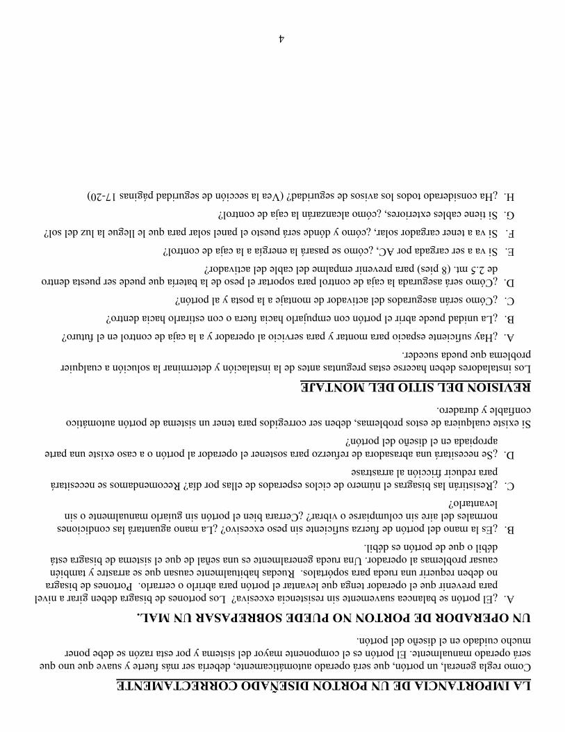
4
LA IMPORTANCIA DE UN PORTON DISEÑADO CORRECTAMENTE Como regla general, un portón, que será operado automáticamente, debería ser más fuerte y suave que uno que será operado manualmente. El portón es el componente mayor del sistema y por esta razón se debe poner mucho cuidado en el diseño del portón.
UN OPERADOR DE PORTON NO PUEDE SOBREPASAR UN MAL. A. ¿El portón se balancea suavemente sin resistencia excesiva? Los portones de bisagra deben girar a nivel
para prevenir que el operador tenga que levantar el portón para abrirlo o cerrarlo. Portones de bisagra no deben requerir una rueda para sopórtalos. Ruedas habitualmente causan que se arrastre y también causar problemas al operador. Una rueda generalmente es una señal de que el sistema de bisagra está débil o que de portón es débil.
B. ¿Es la mano del portón de fuerza suficiente sin peso excesivo? ¿La mano aguantará las condiciones normales del aire sin columpiarse o vibrar? ¿Cerrara bien el portón sin guiarlo manualmente o sin levantarlo?
C. ¿Resistirán las bisagras el número de ciclos esperados de ellas por día? Recomendamos se necesitará para reducir fricción al arrastrase
D. ¿Se necesitará una abrasadora de refuerzo para sostener el operador al portón o a caso existe una parte apropiada en el diseño del portón?
Si existe cualquiera de estos problemas, deben ser corregidos para tener un sistema de portón automático confiable y duradero.
REVISION DEL SITIO DEL MONTAJE Los instaladores deben hacerse estas preguntas antes de la instalación y determinar la solución a cualquier problema que pueda suceder.
A. ¿Hay suficiente espacio para montar y para servicio al operador y a la caja de control en el futuro?
B. ¿La unidad puede abrir el portón con empujarlo hacia fuera o con estirarlo hacia dentro?
C. ¿Cómo serán asegurados del activador de montaje a la posta y al portón?
D. ¿Cómo será asegurada la caja de control para soportar el peso de la batería que puede ser puesta dentro de 2.5 mt. (8 pies) para prevenir empalme del cable del activador?
E. Si va a ser cargada por AC, ¿cómo se pasará la energía a la caja de control?
F. Si va a tener cargador solar, ¿cómo y dónde será puesto el panel solar para que le llegue la luz del sol?
G. Si tiene cables exteriores, ¿cómo alcanzarán la caja de control?
H. ¿Ha considerado todos los avisos de seguridad? (Vea la sección de seguridad páginas 17-20)
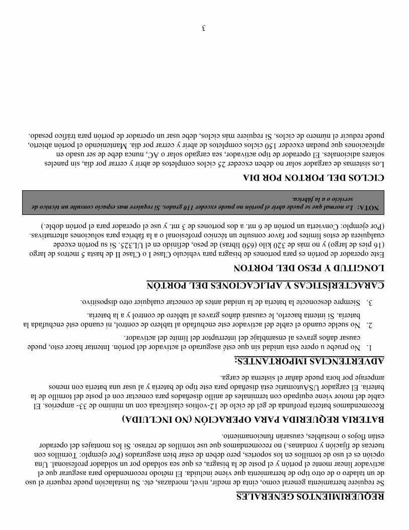
3
REQUERIMIENTOS GENERALES Se requiere herramienta general como, cinta de medir, nivel, mordazas, etc. Su instalación puede requerir el uso de un taladro o de otro tipo de herramienta que viene incluida. El método recomendado para asegurar que el activador linear monte el portón y el poste de la bisagra, es que sea soldado por un soldador profesional. Una opción es el uso de tornillos en los soportes, pero deben de estar bien asegurados (Por ejemplo: Tornillos con tuercas de fijación y rondanas.) no recomendamos que use tornillos de retraso. Si los montajes del operador están flojos o inestables, causarán funcionamiento.
BATERIA REQUERIDA PARA OPERACIÓN (NO INCLUIDA) Recomendamos batería profunda de gel de ciclo de 12-voltios clasificada con un mínimo de 33- amperios. El cable del motor viene equipado con terminales de anillo diseñados para conectar con el poste del tornillo de la batería. El cargador USAutomatic está diseñado para este tipo de batería y al usar una batería con menos amperaje por hora puede dañar el sistema de carga.
ADVERTENCIAS IMPORTANTES: 1. No pruebe u opere esta unidad sin que esté asegurado el activador del portón. Intentar hacer esto, puede
causar daños graves al ensamblaje del interruptor del límite del activador.
2. No suelde cuando el cable del activador este enchufado al tablero de control, ni cuando esté enchufada la batería. Si intenta hacerlo, le causará daños graves al tablero de control y a la batería.
3. Siempre desconecte la batería de la unidad antes de conectar cualquier otro dispositivo.
CARACTERÍSTICAS Y APLICACIONES DEL PORTÓN
LONGITUD Y PESO DEL PORTON Este operador de portón es para portones de bisagra para vehículo Clase I o Clase II de hasta 5 metros de largo (16 pies de largo) y no más de 320 kilo (650 libras) de peso, definido en el UL325. Si su portón excede cualquiera de estos límites por favor consulte un técnico profesional o a la fabrica para soluciones alternativas. (Por ejemplo: Convierta un portón de 6 mt. a dos portones de 3 mt. y use el operador para el portón doble.)
CICLOS DEL PORTON POR DIA Los sistemas de cargador solar no deben exceder 25 ciclos completos de abrir y cerrar por día, sin paneles solares adicionales. El operador de tipo activador, sea cargado solar o AC, nunca debe de ser usado en aplicaciones que puedan exceder 150 ciclos completos de abrir y cerrar por día. Manteniendo el portón abierto, puede reducir el número de ciclos. Si requiere más ciclos, debe usar un operador de portón para tráfico pesado.
NOTA: Lo normal que se puede abrir el portón no puede exceder 110 grados. Si requiere mas espacio consulte un técnico de servicio o a la fábrica.
2
TABLA DE CONTENIDO Página
Introducción ........................................................................................................................ 1
Tabla de Contenido. ........................................................................................................... 2
Requerimientos Generales/ Características y Aplicaciones del Portón. ............................. 3
La Importancia de un Portón diseñado Correctamente ....................................................... 4
Revisión del Sitio de Montaje ............................................................................................. 4
Lista de Partes Incluidas ..................................................................................................... 5
Instalación del Tubo de Montaje/Halar para Abrir/Empujar para Abrir ............................. 6
Instalación del Tubo de Montaje/ Posición Vertical ........................................................... 7
Preparación para la Instalación del Activador .................................................................... 8
Instalación del Activador .................................................................................................... 8
Montaje del Soporte del Portón/ Caja de Control/ Empalme del Cable del Activador ...... 9
Cables del Portón Doble Principal / Auxiliar/ Funciones del Cable de Empujar para Abrir . 10
Instalación Cargado – Solar o AC ....................................................................................11
Instalación de los Carteles de Seguridad/ Sirena Secundaria de Atrapamiento ................ 11
Haciendo Ajustes Finales .................................................................................................. 12
Interruptores de Limite/ Operación de Ensamble del Limite ............................................ 13
Tablero de Control y Descripción de las Terminales........................................................ 14
Interruptores de Programación DS1 .................................................................................. 15
Interruptores de Programación DS2 .................................................................................. 16
Broche Manual de Emergencia ......................................................................................... 16
Sección de Seguridad .................................................................................................. 17-20
Servicio Periódico ............................................................................................................. 21
Guía de Problemas ............................................................................................................ 21
Sección de Problemas ................................................................................................. 21-27
Información de Adicional de los Alambres ................................................................ 27-29
Instalación Y Programación De Un Equipo De Radio ............................................... 30-32
Declaración de la Garantía ............................................................................. Última Página
1
INTRODUCCIÓN Este operador está diseñado para la instalación de puertas de vehículo Clase I o Clase II definido por el UL 325. La carga máxima de la puerta, no debe exceder 320 kilo (650 libras.)
POR FAVOR LEA COMPLETA Y CUIDADOSAMENTE EL MANUAL, ANTES DE LA INSTALACIÓN. Al hacer esto, junto con realizar la instalación en orden gradualmente, usted alcanzará resultados óptimos. Recomendamos fuertemente que el personal de instalación y servicio pongan mucha atención a la sección de sistemas de seguridad de este manual y del UL325. Además del dispositivo de sensor de corriente que está incluida, otros dispositivos de seguridad son necesarios para hacer cada instalación, lo más segura posible, para reducir el riesgo de los daños físicos o daños a la propiedad. Para ayuda, consulte a un técnico especializado o a la fábrica.
©USAutomatic, LTD – 2007 rev ZJ-R2
Bien reservado. Ninguna parte de esto puede ser reproducida por cualquiera significa sin el permiso escrito expresado del editor.
PRECAUCION – MUY IMPORTANTE No intente entrar al área del portón cuando se este moviendo. Espere hasta que el portón se pare
completamente.
Solamente opere el portón cuando esté completamente visible; sin personas u objetos, y ajustado correctamente.
No permita que los niños jueguen en el área del portón. No permita que nadie se monte al portón.
No permitan que los niños jueguen con el control remoto o con ningún dispositivo de activación.
No intente “golpear el portón” mientras que el portón se este abriendo o cerrando. Esto es muy peligroso.
Para asegurar se del funcionamiento correcto, debe probar el abriendo y todos los dispositivos de seguridad regularmente.
Estudie por completo la sección de seguridad (paginas17-20), ponga mucha atención particularmente a las zonas de atrapamiento en páginas 17-20 y esté consciente de estas áreas no solamente durante uso, sino también durante cualquier ajuste a la unidad.
El cargador de batería USAutomatic es designado para operar con batería de 12 vdc que son calculadas de tener un mínimo de 33-amp por hora. Tipo gel son recomendadas.
CON MODIFICAR LA EXTENSION DEL CARGADOR AC ANULARA LA GARANTIA DEL CARGADOR.
Otros Estándares De Seguridad Todas las estaciones de control tienen que estar a lo menos 2 mts. (6 pies) de cualquier parte movible
del portón o el operador.
Nunca instale ningún tipo de dispositivo de control donde el usuario vaya a intentar meter el brazo entre el portón para activarlo.

0
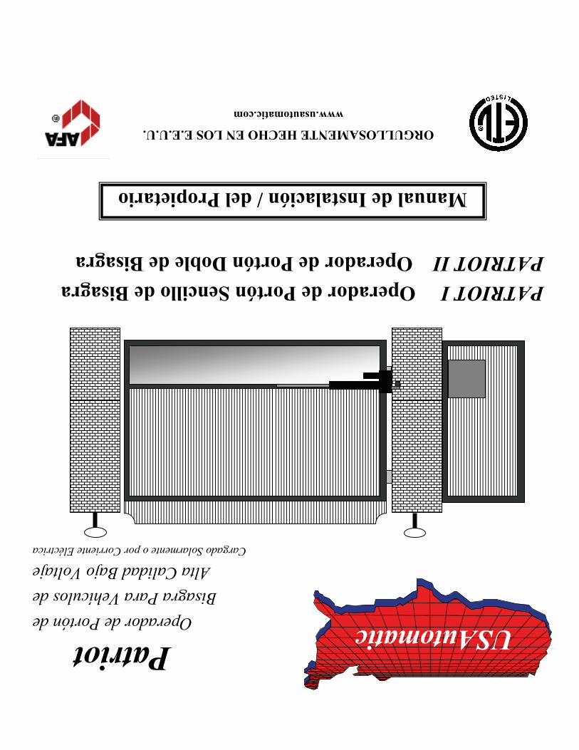
USAutomatic
Patriot
Operador de Portón de Bisagra Para Vehículos de
Alta Calidad Bajo Voltaje Cargado Solarmente o por Corriente Eléctrica
PATRIOT I Operador de Portón Sencillo de Bisagra PATRIOT II Operador de Portón Doble de Bisagra
ORGULLOSAMENTE HECHO EN LOS E.E.U.U. www.usautomatic.com
Manual de Instalación/ del Propietario