Solar Indirect Water Heater with Power Direct Vent Gas Backup Manuals... · following a three...
40
WARNING Improper installation, adjustment, alteration, service or maintenance can cause serious injury or property damage. Refer to this manual. For assistance or additional information, consult a qualified installer or service agency. WARNING If the information in these instructions is not followed exactly, a fire or explosion may result causing property damage, personal injury or death. WARNING Install in accordance with all local codes. In the absence of local codes, refer to ANSI 223.1/NFPA 54 and/or CSA B149.1. CAUTION The recommended temperature for normal residential use is 120°F. The dial on the aquastat does not always reflect the out-coming water temperature and it could occasionally exceed 120°F. Variation in out-coming temperature could be based on factors including but not limited to usage patterns and type of installa- tion. Test water at the tap nearest to the water heater. See page 32 for measuring the out- coming water temperature. WARNING Hotter water increases the risk of scald injury. Before adjusting the water temperature setting, read this instruction manual. Temperatures at which injury occurs vary with the person’s age and the length of exposure. The slower reaction time of children, elderly or physically or mentally challenged persons increases the scalding hazard to them. It is recommended that lower water temperatures be used where these exposure hazards exist. Households with small children or invalids may require a temperature setting less than 120°F to prevent accidental contact with hot water. To produce less than 120°F, use point-of-use temperature limiting devices. If higher water temperature is needed in part of the water system, automatic temperature limiting devices must be used on all lines to water taps. WARNING Flammable vapors may be drawn to this water heater from other areas of the structure by air currents. Do not store or use any flammable liquids in the vicinity of this heater. WARNING Water heater blankets may restrict air flow to the water heater and cause fire, asphyxiation, personal injury or death. THIS MANUAL HAS BEEN PREPARED TO ACQUAINT YOU WITH THE INSTALLATION, OPERATION, AND MAINTENANCE OF YOUR WATER HEATER AND TO PROVIDE IMPORTANT SAFETY INFORMATION. Read all instructions thoroughly before attempting installation or operation of your water heater. Keep these instructions for future reference. Local plumbing and electrical codes must be followed in the installation of this water heater. In the absence of a local code use the UNIFORM PLUMBING CODE and the NFPA Code. Local codes may supersede instructions in this installation manual. These instructions are a guide for the correct installation of the water heater. The manufac- turer will not be liable for damages caused by failure to comply with the installation and operating instructions outlined on the following pages. Installation, testing, and replacement of gas piping, appliances, or accessories, and repair and servicing of equipment, shall be performed only by a qualified agency. FAILURE TO FOLLOW THESE INSTRUCTIONS OR ALL APPLICABLE BUILDING CODES AND REGULATIONS VOIDS THE WARRANTY ON THIS WATER HEATER. Warranty, Registration Card and Parts List are included. Homeowner: Please remember to return the Registration Card! To the Consumer: Please read these and all component instructions and keep for future reference. To the Installer: Please attach these instructions next to the water heater. Rev 3 6/16 Installation and Operation Instructions Manual 23419 Models: 75-76SKG, 100-76SKG Solar Indirect Water Heater with Power Direct Vent Gas Backup
Transcript of Solar Indirect Water Heater with Power Direct Vent Gas Backup Manuals... · following a three...
WARNINGImproper installation, adjustment, alteration,service or maintenance can cause seriousinjury or property damage. Refer to thismanual. For assistance or additionalinformation, consult a qualified installer orservice agency.
WARNINGIf the information in these instructions is notfollowed exactly, a fire or explosion may resultcausing property damage, personal injury ordeath.
WARNINGInstall in accordance with all local codes. In the absence of local codes, refer to ANSI223.1/NFPA 54 and/or CSA B149.1.
CAUTIONThe recommended temperature for normalresidential use is 120°F. The dial on the aquastatdoes not always reflect the out-coming watertemperature and it could occasionally exceed120°F. Variation in out-coming temperaturecould be based on factors including but notlimited to usage patterns and type of installa-tion. Test water at the tap nearest to the waterheater. See page 32 for measuring the out- coming water temperature.
WARNINGHotter water increases the risk of scald injury.Before adjusting the water temperature setting,read this instruction manual. Temperatures atwhich injury occurs vary with the person’s ageand the length of exposure. The slowerreaction time of children, elderly or physicallyor mentally challenged persons increases thescalding hazard to them. It is recommendedthat lower water temperatures be used wherethese exposure hazards exist. Households withsmall children or invalids may require atemperature setting less than 120°F to preventaccidental contact with hot water. To produceless than 120°F, use point-of-usetemperature limiting devices.
If higher water temperature is needed in partof the water system, automatic temperaturelimiting devices must be used on all lines towater taps.
WARNINGFlammable vapors may be drawn to this waterheater from other areas of the structure by aircurrents. Do not store or use any flammableliquids in the vicinity of this heater.
WARNINGWater heater blankets may restrict air flow tothe water heater and cause fire, asphyxiation,personal injury or death.
THIS MANUAL HAS BEEN PREPARED TO ACQUAINT YOU WITH THE INSTALLATION,
OPERATION, AND MAINTENANCE OF YOURWATER HEATER AND TO PROVIDE IMPORTANT
SAFETY INFORMATION.
Read all instructions thoroughly beforeattempting installation or operation of yourwater heater. Keep these instructions for futurereference.
Local plumbing and electrical codes must befollowed in the installation of this waterheater. In the absence of a local code use theUNIFORM PLUMBING CODE and the NFPACode. Local codes may supersede instructionsin this installation manual.
These instructions are a guide for the correctinstallation of the water heater. The manufac-turer will not be liable for damages caused byfailure to comply with the installation and operating instructions outlined on the following pages.
Installation, testing, and replacement of gaspiping, appliances, or accessories, and repairand servicing of equipment, shall beperformed only by a qualified agency.
FAILURE TO FOLLOW THESE INSTRUCTIONSOR ALL APPLICABLE BUILDING CODES
AND REGULATIONS VOIDS THE WARRANTYON THIS WATER HEATER.
Warranty, Registration Card and Parts List are included.Homeowner: Please remember to return the Registration Card!
To the Consumer:Please read these and all component instructions and keep for future reference.
To the Installer:Please attach these instructions next to the water heater.
Rev 3 6/16
Installation and Operation Instructions Manual
23419
Models: 75-76SKG, 100-76SKG
Solar Indirect Water Heater with Power Direct Vent Gas Backup
Page 2
IMPORTANT SAFETY INSTRUCTIONS
FOR YOUR SAFETY!- Do not store or use gasoline or other flammable vapors and liquids in thevicinity of this or any other appliance.
- WHAT TO DO IF YOU SMELL GAS
• Do not try to light any appliance.
• Do not touch any electrical switch; do not use any phone in your building.
• Immediately call your gas supplier from a neighbor’s phone. Follow the gas supplier’s instructions.
• If you cannot reach your gas supplier, call the fire department.
- Installation and service must be performed by a qualified installer, service agency or the gas supplier.
SAVE THESE INSTRUCTIONS
WARNINGIf the information in these instructions is not followed exactly, a fire or explosion may result causing property damage, personal injury or death.
DANGERWater heaters utilizing Liquefied Petroleum gas (LP) are different from natural gas models. A natural gas heater will not function safely on LP gasand vice versa. To avoid possible equipment damage, personal injury orfire: DO NOT connect this water heater to a fuel type not in accordancewith the rating label. These units are only certified for a single fuel type.
DANGERFailure to properly install the vent and combustion air intake system asoutlined in this manual can result in unsafe operation of the water heater.To avoid the risk of fire, explosion, or asphyxiation from carbon monoxide,never operate this water heater unless it is properly vented and hasadequate air supply for combustion and dilution of flue gas. Be sure toinspect the system for proper installation at initial start-up; and at least annually thereafter. See the Maintenance section for more information.

Page 3
TABLE OF CONTENTS
Section I: Specifications . . . . . . . . . . . . . . . . . . . . . . . . . . . . . . . . . . . . . . . . . . . . . 4
Section II: General Information. . . . . . . . . . . . . . . . . . . . . . . . . . . . . . . . . . . . . . . . 5
Section III: Pre-Installation . . . . . . . . . . . . . . . . . . . . . . . . . . . . . . . . . . . . . . . . . . . 7
Section IV: Installation . . . . . . . . . . . . . . . . . . . . . . . . . . . . . . . . . . . . . . . . . . . . . 10
Section V: Operation . . . . . . . . . . . . . . . . . . . . . . . . . . . . . . . . . . . . . . . . . . . . . . . 30
Section VI: Maintenance . . . . . . . . . . . . . . . . . . . . . . . . . . . . . . . . . . . . . . . . . . . . 33
Section VII: Troubleshooting . . . . . . . . . . . . . . . . . . . . . . . . . . . . . . . . . . . . . . . . . 35
Section VIII: Parts List. . . . . . . . . . . . . . . . . . . . . . . . . . . . . . . . . . . . . . . . . . . . . . . 37
Section IX: Warranty . . . . . . . . . . . . . . . . . . . . . . . . . . . . . . . . . . . . . . . . . . . . . . . 39

Model
Storage GAL (L)
Rated Input
BTU/HR (kW)
Table 1: Dimensions
Page 4
SECTION I: SPECIFICATIONS
NO
BEND ±
F
D
E
AB
C
H
I
Gas/Temp.Control
T&P Relief Valve
HOT (Space heating supply)
COLD(Space heating return)
FROM SOLAR
TO SOLAR
Gas backuptemp. sensor & ECO
Solar sensor immersion well
G
COLDHOT
Anode
Figure 1: All Models
Recovery @ 77
o F rise
GAL/HR (L/HR)
A B C D E F G H I Outlet Conn. Dia.
(NPT)
Aux. Conn. Dia.
(NPT)
Gas Conn. Dia.
(NPT)
Shipping Weight
LBS (kg)
DIMENSIONS INCHES (cm)
For LP models change suffix "N" to "LP"Working Pressure: 150 PSI (1034 kPa)Test Pressure: 300 PSI (2068 kPa)For natural gas: Manifold pressure = 4" W.C. (1.00 kPa); Inlet pressure range 5-14" W.C. (1.25 - 3.49 kPa)For propane gas: Manifold pressure = 10" W.C. (1.00 kPa); Inlet pressure range 11-14" W.C. (2.74 - 3.49 kPa)T&P valve installedAll Bock products meet or exceed current ASHRAE standards.These products are design certified by UL (Underwriters Laboratories) and meet ANSI Z21.10.3 / CSA 4.3 requirements for operation up to 180°F (82°C).Approved for use as a direct vent automatic storage water heater.WARNING: Installation shall be in accordance with all national and/or local codes. In the absense of local codes, refer to NFPA 54 and/or CSA B149.1.CAUTION: The recommended maximum hot water temperature setting for normal residential use is 120°F (49°C). Bock recommends a tempering valve or anti-scald valve be installed and used according to the manufacturer's directions to prevent scalding.
1st Hr. Delivery @
77o F rise GAL (L)
Inlet Conn. Dia.
(NPT)
73 76000 96 136 76.88 67.25 26.00 60.00 28.19 16.00 11.00 43.50 18.50 1.00 1.00 1.00 0.50 469 (276) (22.3) (363) (515) (195) (171) (68) (152) (72) (41) (28) (110) (47) (213)
98 76000 96 154 76.88 67.25 28.00 60.00 28.19 16.00 11.00 43.50 18.50 1.00 1.00 1.00 0.50 572 (371) (22.3) (363) (583) (195) (171) (71) (152) (72) (41) (28) (110) (47) (259)
75-76SKGN
100-76SKGN
GAS-FIRED ONLY
SOLAR ONLY
2.76 (10.45) 14.14 (1.31) 0.6 32 (121) 98 (371)
2.76 (10.45) 14.14 (1.31) 0.6 32 (121) 121 (458)
Model
75-76SKGN
100-76SKGN
Coil Volume Coil Surface Area Coil Friction Loss Recovery*** 1st Hr. Delivery*** GAL (L) FT2 (m2) @ 5 GPM @ 77°F rise @ 77°F rise (feet w.c.) GAL/HR (L/HR) GAL (L)
***Input to coil: 140°F, 2 GPM

Page 5
SECTION II: GENERAL INFORMATION
WHEN YOU RECEIVE YOUR NEW WATER HEATERCheck the new equipment to see if all components are in good condition. If damage isobserved or parts appear to be missing, contact your wholesaler.
WATER TREATMENT/FILTRATIONIn areas where poor water conditions are suspected (i.e. lime, iron, and other minerals), it isessential that the water be tested and appropriate action taken to prevent damage to the water heater and ensure the quality of the water.
SOLAR WATER HEATER FUNCTION The solar water heater is designed with an internal coil and gas burner for backup heating. A heating medium is passed through the solar panels and internal coil as long as there is anadequate temperature difference between the heating medium and stored water in the tank.The internal coil is located as close to the bottom as possible to facilitate the transfer of heateven at lower solar panel temperatures.
During periods of water flow through the water heater, hot water is drawn from the top of theheater and cold water is delivered to the bottom of the tank (by a diptube). If the hot waterdemand should exceed the solar heat output or there is an insufficient temperature differencebetween the heating medium and stored water, the gas-fired backup thermostat will activatethe burner for backup heat.
Solar heat output from the internal coil will vary depending on outside conditions and thetemperature of the stored water. The temperature sensor for the gas backup is higher in thetank to delay burner operation. To further limit the operation of backup heating, connect thewater heater to a programmable timer. Limiting the gas backup operation to off-peak solartime can increase solar gain in the stored water.
TEMPERATURE CONTROLThe water heater is equipped with a combination gas valve, ignition control, and thermostatto operate the gas backup system. For domestic hot water, the proper temperature setting is120°F (i.e. “WARM” setting on control). For commercial applications, the maximum approvedtemperature setting is 180°F (i.e. “F” setting on control).
A built-in, automatic reset Energy Cut-Off (ECO) is standard on all models. In the event thatthe water temperature becomes excessive (195°F), the ECO will shut off all gas to the waterheater. If the ECO switch opens, it will automatically reset (or close) when the watertemperature drops to 120°F or below. The water heater thermostat will automatically resetfollowing a three minute standby period once the ECO switch closes.
The thermostat is factory set at 120°F. See Figure 21 for temperature and display settings. If hotter water is required a tempering device or anti-scald device must be installed at thedomestic hot water outlet of the heater or at the point of use. Table 3 details the approximaterelationship of water temperature and time with regard to scald injury. It is important for theuser to understand the necessity of tempering or anti-scald devices when using hotter water indomestic water heating systems.
CAUTION: Hot water in excess of 120°F can cause scalding!
Bock recommends a tempering valve or anti-scald valve be installed and used according tothe manufacturer’s directions to prevent scalding. Many state and local codes now requireinstallation of these devices. Point of use temperature may be hotter than the setting on thewater heater thermostat. The tempering valve or anti-scald valve will ensure potablewater temperatures at the desired set point with a higher degree of accuracy.
Page 6
SECTION II: GENERAL INFORMATION (cont.)
TEMPERATURE CONTROL (cont.)
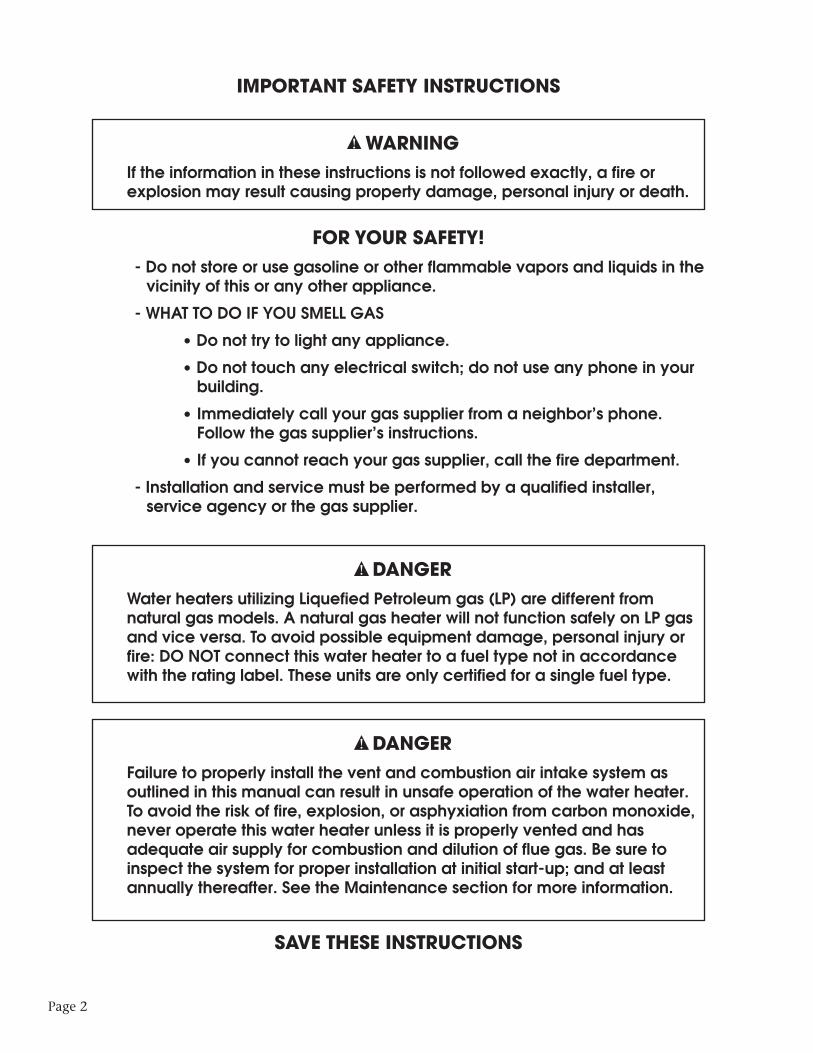
ANODE RODSThe anode rod is used as a sacrificial element within the volume of the storage tank. The purpose ofthe magnesium anode rod is to protect the inside of the tank against corrosion. Anode rods shouldbe inspected twice in the first year and at least yearly once a time interval for inspection has beendeveloped. Water conditions can influence the consumption rate of the anode rods. Please see theMaintenance section of this manual for instructions on how to change the anode rods.
CAUTION
Hydrogen gas is produced in a hot water system served by the heater that has not beenused for a long period of time (2 weeks or more). Hydrogen gas is extremely flammable.To reduce the risk of injury under these conditions, it is recommended that the hot waterfaucet be opened for several minutes at the kitchen sink before using any electricalappliance connected to the hot water system. When hydrogen is present, there willprobably be an unusual sound such as air escaping through the pipe as the water beginsto flow. There should be no smoking or open flame near the faucet at the time it is open.
TEMPERATURE AND PRESSURE RELIEF VALVE (T&P)
CAUTION
To reduce the risk of excessive pressures and temperatures in this water heater, installtemperature and pressure protective equipment required by local codes and no lessthan a combination temperature and pressure relief valve certified by a nationallyrecognized testing laboratory that maintains periodic inspection of production of listedequipment or materials, as meeting the requirements for Relief Valves and AutomaticGas Shutoff Devices for Hot Water Supply Systems, ANSI Z21.22. This valve must bemarked with a maximum set pressure not to exceed the marked maximum workingpressure of the water heater. Install the valve in an opening provided and marked forthis purpose in the water heater, and orient it or provide tubing so that any dischargefrom the valve exits only within 6 inches above, or at any distance below, the structuralfloor, and does not contact any live electrical part. The discharge opening must not beblocked or reduced in size under any circumstances.
APPROXIMATETEMPERATURE/TIMERELATIONSHIPS TO
SCALDING
120°F (49°C) More than 5 minutes
125°F (52°C) 1 1⁄2 to 2 minutes
130°F (54°C) About 30 seconds
135°F (57°C) About 10 seconds
140°F (60°C) Less than 5 seconds
145°F (63°C) Less than 3 seconds
150°F (66°C) About 1 1⁄2 seconds
155°F (68°C) About 1 second
Table 2: Scald Temperature/Time Relationships
Page 7
SECTION II: GENERAL INFORMATION (cont.)
TEMPERATURE AND PRESSURE RELIEF VALVE (T&P) (cont.)
CAUTION
Scalding injury and/or water damage can occur from either the manual lifting of the lever or the normal operation of the T&P valve. If it is not piped to a proper drain. If the valve fails to flow water or reseat, call your plumber.
The T&P valve is factory installed. A discharge drain tube must be installed (responsibility of the installer) and shall terminate plain, not threaded, 6 inches above the floor drain. The drain tube material must be approved for temperatures of 120o F or greater and a pressure of 150 PSI or greater.
BACKFLOW PREVENTER (CLOSED SYSTEM)Some local municipal codes and ordinances require the use of these devices on potable(domestic) water lines. Where backflow preventers, check valves, or pressure regulating valvesare required, it will be necessary to install a thermal expansion tank (designed for use withpotable water) in order to prevent pressure build up in the water heater and associated piping,which could cause the T&P valve to discharge. Follow the expansion tank manufacturer’srecommendations when selecting a tank for your hot water system. The expansion tankpressure shall equal the water heater system pressure prior to initial warm up.
Note: Working pressure of the water heater is 150 PSI. Do not exceed 150 PSI.
CONDENSATIONIn some installations condensation will occur in the venting (exhaust) system. It is importantto not allow condensate to collect around mechanical components and bare metal parts onthe water heater. Therefore, if condensation occurs in the venting system it must be routed toa proper area for drainage. Horizontal sections of the vent system shall slope downward awayfrom the water heater a minimum of 1/8" per foot. When downward sloping of the ventsystem is not possible or a vertical vent arrangement is used, the condensate drain kit must beinstalled. See Section IV: Installation / Vent and Combustion Air Intake / Condensate DrainKit for installation details.
HIGH ALTITUDEContact Bock Water Heaters for installations at altitudes greater than 2,000 feet above sea level.
SECTION III: PRE-INSTALLATION
LOCATIONCAUTION
This water heater must be located in an area where leakage of the tank, water lineconnections, or the temperature and pressure relief valve will not result in damage to thearea adjacent to the water heater or to lower floors of the structure. When such locationcannot be avoided, a suitable drain pan must be installed under the water heater. Thedrain pan depth must be suitable for draining and collecting water. The drain pan can bepurchased from your plumbing professional. The drain pan must be piped to an adequatedrain and all drain piping must be at least 0.75” in diameter and pitched for proper drainage.

Page 8
SECTION III: PRE-INSTALLATION (cont.)
CAUTION
DO NOT store or use gasoline or other flammable, combustible, or corrosive vaporsand/or liquids in the vicinity of the water heater or any other appliance.
IF YOU SMELL GAS: • DO NOT try to light any appliance. • DO NOT touch any electric switch; do not use any telephone in your building. • Immediately call your gas supplier from a telephone in another building. Follow your
gas supplier’s instructions. • If you cannot reach your gas supplier, call the fire department. DO NOT OPERATE THE APPLIANCE UNTIL THE LEAKAGE IS CORRECTED!
CAUTION Do not drop water heater or lay heater down on its side. Move the water heater into
position by sliding or using an appropriately sized hand truck.
CAUTION If the water heater is installed directly on carpeting, the water heater shall be installed
on a metal or wood panel extending beyond the full width and depth of the waterheater by at least 3 inches (76.2 mm) in any direction or, if the water heater is installedin an alcove or closet, the entire floor shall be covered by the panel. The panel must bestrong enough to carry the weight of the heater when full of water.
NOTE: Locate the heater so it is not subject to physical damage from moving vehicles orflooding. Do not locate the water heater in a room where swimming pool chemicals or largequantities of water softener salt are kept. Installing a water heater in this environment willresult in premature failure of tank and burner components due to corrosion caused by theseelements diffusing into the air.
The water heater can be installed on combustible or non-combustible flooring. Maintainclearances specified in this manual and in accordance with the National Fuel Gas Code (NFPA54, ANSI Z223.1) unless otherwise directed by state and local code requirements. Locate thewater heater such that plastic vent pipe lengths and the number of connection fittings areminimized.
Minimum clearances from combustible construction are:Table 3: Clearances
1) Measured from water heater jacket to wall. This clearance accommodates the air intakeboot.2) Measured from jacket to closet door.3) Measured from water heater top to ceiling.
This water heater is approved for installation in a closet or alcove with the clearances above.
SIDES BACK1 FRONT2 TOP3
0 in. (0 cm) 6 in. (15 cm) 24 in. (61 cm) 26 in. (66 cm)

Page 9
SECTION III: PRE-INSTALLATION (cont.)
COMBUSTION AND VENTILATION AIRThe water heater can be installed to utilize combustion air from either inside or outside thebuilding. Refer to "Section IV: Installation" for detailed venting specifications. If indoor air isused for combustion air it is imperative that the room has an adequate air supply. Inadequateair supplies may lead to unsafe levels of carbon monoxide (CO), condensation of flue gases,and excessive levels of soot. See NFPA 54 or the discussions of "Unconfined Space" and"Confined Space" below. In addition, poor ventilation will also result in hot spots around theheater. Temperatures over 90°F near the water heater generally indicate a lack of ventilation.
UNCONFINED SPACEUnconfined space is defined by NFPA 54 as a space with a volume greater than 50 cubic feet(during typical use) per 1000 BTUH of the total combined input of all fuel burning appliancesin the space. Rooms leading directly to the installation space through doors that cannot beclosed can be considered part of the space. Exception: Buildings with full vapor barriers, tightdoors and windows or air infiltration rates of less than 0.35 air changes per hour will beconsidered a confined space and require additional air supplies.
CONFINED SPACEConfined space is defined by NFPA 54 as a space with a volume less than 50 cubic feet (duringtypical use) per 1000 BTUH of the total combined input of all fuel burning appliances in thespace. Buildings or rooms of unusually tight construction are also considered a confinedspace. See “Unconfined Space: Exception”.When installing fuel burning appliances in a confined space, air must be supplied to thatspace from either inside or outside of the building as conditions allow.A. Inside Air Supply: A confined space shall be provided with two permanent openings; onewithin 12 inches of the top and one within 12 inches of the bottom of the enclosure. Theseopenings shall lead directly to room(s) of sufficient volume so that the combined volume ofall the space meets the criteria for unconfined space. Each opening shall have a minimum freearea of 1 square inch per 1000 Btu/hr of the combined total input of all fuel burningappliances in the space. Each opening shall have an area of not less than 100 square inches ora minimum dimension of not less than 3 inches.B. Outside Air Supply: Confined spaces shall be provided with two permanent openings; onewithin 12 inches of the top and one within 12 inches of the bottom of the enclosure. Theseopenings shall communicate directly, or by ducts, with the outdoors or spaces that communicate with the outdoors.1.) Leading directly to the outside or through vertical ducts: Each opening shall have aminimum free area of one square inch per 4000 Btu/hr of total input rating of all equipmentin the enclosure.2.) Leading to outside through horizontal ducts: Each opening shall have a minimum freearea of one square inch per 2000 Btu/hr of total input rating of all equipment in the enclosure.Note: All ducts shall have the same cross sectional area as the free area of each opening towhich they connect. The minimum dimensions of all ducts shall not be less than three inches.Powered combustion air supplies are also commercially available and may be used.
LOUVERS & GRILLESIn calculating the free area of an opening, consideration must be given to the blocking effectsof louvers or grilles protecting the opening. Any screens used must be no finer than 1⁄4 inchmesh. If the free area of a louver or grille is known, this should be used in calculating the sizeof opening required. If free area is unknown, it may be assumed that wood louvers will have20 to 25% free area and metal louvers and grilles will have 60 to 75% free area. Louvers andgrilles should be fixed in the open position or interlocked with the equipment so that theyopen automatically during equipment operation.

SECTION IV: INSTALLATION
VENT & COMBUSTION AIR INTAKE
DANGER Failure to properly install the vent and combustion air intake system as outlined in this
manual can result in unsafe operation of the water heater. To avoid the risk of fire,explosion, or asphyxiation from carbon monoxide, never operate this water heaterunless it is properly vented and has adequate air supply for combustion and dilution offlue gas. Be sure to inspect the system for proper installation at initial start-up; and atleast annually thereafter. See the Maintenance section for more information.
The water heater venting and combustion air intake can be installed as a power directvent system (combustion air from outside the building) or power vent system(combustion air from inside the building). Vertical or horizontal (side-wall) configura-tions may be used with a two-pipe or concentric vent termination.
Note: If air from inside the building will be used for combustion air, the require-ments in Section III, "Unconfined Space" must be met.
The water heater is supplied with a rubber coupling (with clamps) that connects to theblower assembly outlet. The air intake piping is preassembled to route dilution air to theblower assembly and combustion air to the burner chamber. All vent length measure-ments specified in this manual are in addition to the preassembled piping supplied withthe water heater. Equivalent pipe run lengths shall not be greater than the maximumlengths (or less than minimums) given in Tables 4 and 5.
Note: DO NOT connect the water heater to an existing vent or chimney. It mustbe vented separately from all other appliances.
The following materials are approved for use as the vent and combustion air intakepiping:
• PVC (DWV, ASTM-D2665 or CSA B181.2)• PVC (Schedule 40, ASTM-D1785 or CSA B137.3)• PVC (SDR Series, ASTM-D2241 or CSA B137.3)• CPVC (Schedule 40, ASTM-F441 or CSA B137.3)• CPVC (SDR Series, ASTM-F442)• ABS (Schedule 40, DWV, ASTM-D2661 or CSA B181.1)
In Canada, check local codes to ensure that SDR series is approved for use. SDR isnot approved for all installations in Canada.
The following materials are approved for use for the fittings in the vent and combustionair intake systems:
• PVC (Schedule 40 DWV, ASTM D2665)• CPVC (Schedule 40, ASTM F438)• ABS (Schedule 40 DWV, ASTM D2661)
Please contact Bock Water Heaters for questions regarding materials that are not listedabove.
Page 10
SECTION IV: INSTALLATION (cont.)
VENT & COMBUSTION AIR INTAKE (cont.)
NOTICE Installations in Canada must conform to the requirements of CSA B149 code. Plastic
vent systems must be assembled with pipe, fittings, cements, and primers listed to ULCS636. Components of this listed system shall not be interchanged with other ventsystems or unlisted pipe/fittings. In Canada, the primer and cement must be of thesame manufacturer as the vent system; do not mix primers and cements from onemanufacturer with a vent system from a different manufacturer. The supplied plasticpipe/fittings are certified as part of the water heater.
Minimum and Maximum System Lengths
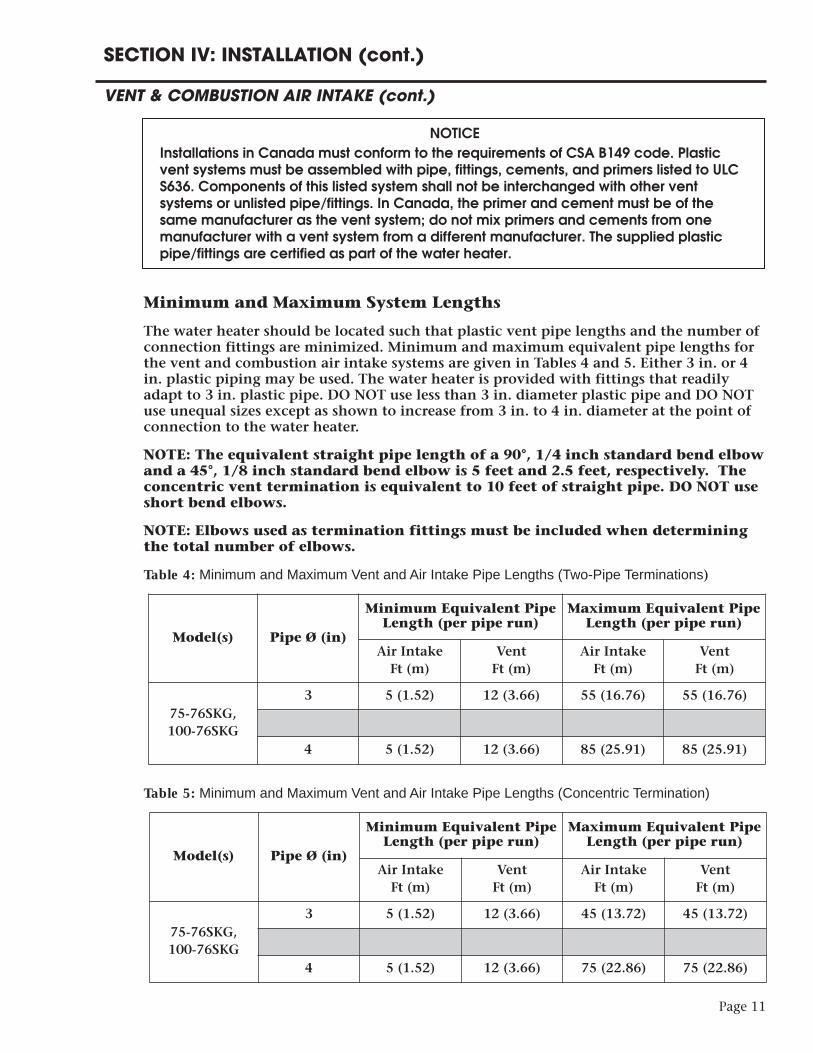
The water heater should be located such that plastic vent pipe lengths and the number ofconnection fittings are minimized. Minimum and maximum equivalent pipe lengths forthe vent and combustion air intake systems are given in Tables 4 and 5. Either 3 in. or 4in. plastic piping may be used. The water heater is provided with fittings that readilyadapt to 3 in. plastic pipe. DO NOT use less than 3 in. diameter plastic pipe and DO NOTuse unequal sizes except as shown to increase from 3 in. to 4 in. diameter at the point ofconnection to the water heater.
NOTE: The equivalent straight pipe length of a 90°, 1/4 inch standard bend elbowand a 45°, 1/8 inch standard bend elbow is 5 feet and 2.5 feet, respectively. Theconcentric vent termination is equivalent to 10 feet of straight pipe. DO NOT useshort bend elbows.
NOTE: Elbows used as termination fittings must be included when determiningthe total number of elbows.
Table 4: Minimum and Maximum Vent and Air Intake Pipe Lengths (Two-Pipe Terminations)
Table 5: Minimum and Maximum Vent and Air Intake Pipe Lengths (Concentric Termination)
Page 11
Model(s) Pipe Ø (in)
Minimum Equivalent PipeLength (per pipe run)
Maximum Equivalent PipeLength (per pipe run)
Air IntakeFt (m)
VentFt (m)
Air IntakeFt (m)
VentFt (m)
75-76SKG,100-76SKG
3 5 (1.52) 12 (3.66) 55 (16.76) 55 (16.76)
4 5 (1.52) 12 (3.66) 85 (25.91) 85 (25.91)
Model(s) Pipe Ø (in)
Minimum Equivalent PipeLength (per pipe run)
Maximum Equivalent PipeLength (per pipe run)
Air IntakeFt (m)
VentFt (m)
Air IntakeFt (m)
VentFt (m)
75-76SKG,100-76SKG
3 5 (1.52) 12 (3.66) 45 (13.72) 45 (13.72)
4 5 (1.52) 12 (3.66) 75 (22.86) 75 (22.86)

For quick reference, Tables 6 and 7 give the maximum allowable length of straight pipebased on the total number of elbows per pipe run.
Table 6: Maximum Pipe Lengths Quick Reference (Two-Pipe Terminations)
Table 7: Maximum Pipe Lengths Quick Reference (Concentric Termination)
Page 12
Model(s) Pipe Ø (in)# of 90° Elbows per
pipe run(including termination fittings)
Maximum Equivalent PipeLength (per pipe run)Air IntakeFt (m)
VentFt (m)
75-76SKG,100-76SKG
3 0 55 (16.76) 55 (16.76)
3 1 50 (15.24) 50 (15.24)
3 2 45 (13.72) 45 (13.72)
3 3 40 (12.19) 40 (12.19)
3 4 35 (10.67) 35 (10.67)
3 5 30 (9.14) 30 (9.14)
3 6 25 (7.62) 25 (7.62)
4 0 85 (25.91) 85 (25.91)
4 1 80 (24.38) 80 (24.38)
4 2 75 (22.86) 75 (22.86)
4 3 70 (21.34) 70 (21.34)
4 4 65 (19.81) 65 (19.81)
4 5 60 (18.29) 60 (18.29)
4 6 55 (16.76) 55 (16.76)
Model(s) Pipe Ø (in)# of 90° Elbows per
pipe run(including termination fittings)
Maximum Equivalent PipeLength (per pipe run)Air IntakeFt (m)
VentFt (m)
75-76SKG,100-76SKG
3 0 45 (13.72) 45 (13.72)
3 1 40 (12.19) 40 (12.19)
3 2 35 (10.67) 35 (10.67)
3 3 30 (9.14) 30 (9.14)
3 4 25 (7.62) 25 (7.62)
3 5 20 (6.10) 20 (6.10)
3 6 15 (4.57) 15 (4.57)
4 0 75 (22.86) 75 (22.86)
4 1 70 (21.34) 70 (21.34)
4 2 65 (19.81) 65 (19.81)
4 3 60 (18.29) 60 (18.29)
4 4 55 (16.76) 55 (16.76)
4 5 50 (15.24) 50 (15.24)
4 6 45 (13.72) 45 (13.72)
SECTION IV: INSTALLATION (cont.)
VENT & COMBUSTION AIR INTAKE (cont.)
The vent and combustion air intake systems must be sufficiently supported alongvertical and horizontal sections. At minimum, it is recommended that a support is placedalong the vent or air intake piping every 4 feet. For horizontal systems, the first support shallbe located immediately adjacent to the first 90-deg. elbow following the vertical sectionconnected to the water heater. The support method should act to isolate the vent andcombustion air intake piping from floor joists or other structural members to reduce transmis-sion of noise and vibration.
NOTE: Do not support, pin, or secure the vent and combustion air intake pipe in away that restricts the normal thermal expansion and contraction of the ventingmaterial.
For replacement installations, thoroughly inspect the existing vent and combustion air intakesystems prior to installing the new water heater. The following steps shall be taken to properlyinspect the existing vent system:
• Verify that the materials as specified in this manual have been used.
• Verify the maximum and minimum vent and combustion air intake equivalent lengths andterminal clearances meet the specifications in this manual.
• Inspect the vent and combustion air intake systems for cracking. Pay close attention to jointsbetween elbows and straight pipe.
• Inspect the system for misalignment of components. This may lead to sagging and unwantedstresses in the joints.
If any corrections are required they must be computed before installing the replacement waterheater.
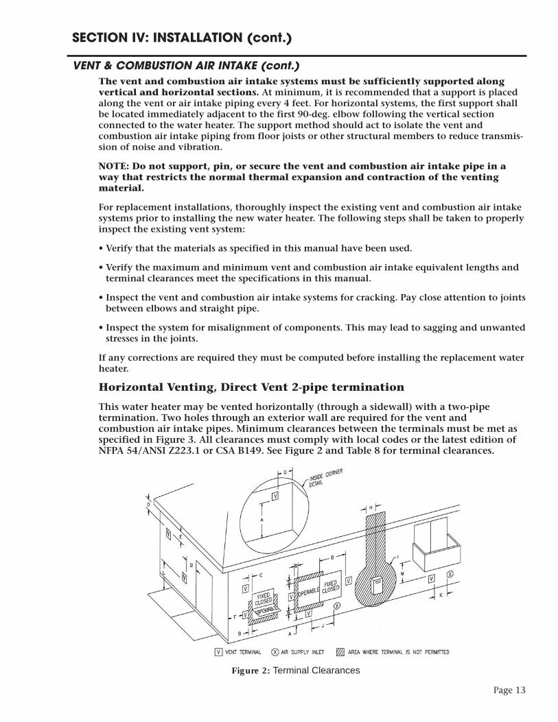
Horizontal Venting, Direct Vent 2-pipe termination
This water heater may be vented horizontally (through a sidewall) with a two-pipetermination. Two holes through an exterior wall are required for the vent andcombustion air intake pipes. Minimum clearances between the terminals must be met asspecified in Figure 3. All clearances must comply with local codes or the latest edition ofNFPA 54/ANSI Z223.1 or CSA B149. See Figure 2 and Table 8 for terminal clearances.
Page 13
SECTION IV: INSTALLATION (cont.)
VENT & COMBUSTION AIR INTAKE (cont.)
Figure 2: Terminal Clearances

1 In accordance with the current CSA B149.1 Natural Gas and Propane Installation Code.2 In accordance with the current ANSI Z223.1 / NFPA 54 National Fuel Gas Code.† A vent shall not terminate directly above a sidewalk or paved driveway that is located between two single familydwellings and serves both dwellings.Permitted only if veranda, porch, deck, or balcony is fully open on a minimum of two sides beneath the floor.
* Clearance in accordance with local installation codes and the requirements of the gas supplier.
In addition to the clearances specified, the following items shall be accounted for duringinstallation:• Do not terminate near soffit vents or crawl space or other area where condensate orvapor could create a nuisance hazard or cause property damage.
• Do not locate the exhaust vent terminal where condensate or vapor could cause damageor could be detrimental to the operation of regulators, relief valves, or other equipment.
• Do not locate the exhaust vent terminal over public area or walkways where condensateor vapor can cause nuisance or hazard.
• Do not locate the vent terminal in proximity to plants/shrubs.• The vent and air intake shall terminate a minimum of 12" (25.4 cm) above expectedsnowfall level to prevent blockage.
CAUTION
Never install air intake terminal above vent (exhaust) terminal.
Page 14
SECTION IV: INSTALLATION (cont.)
VENT & COMBUSTION AIR INTAKE (cont.)
Table 8: Direct Vent Terminal ClearancesCanadian Installations1 US Installations2
A = Clearance above grade, veranda,porch, deck, or balcony 12 inches (30 cm) 12 inches (30 cm)
B = Clearance to window or door thatmay be opened 12 inches (30 cm) 12 inches (30 cm)
C = Clearance to permanently closedwindow * *D = Vertical clearance to ventilatedsoffit located above the terminal withina horizontal distance of 2 feet (61 cm)from the centerline of the terminal
* *
E = Clearance to unventilated soffit * *
F = Clearance to outside corner * *
G = Clearance to inside corner * *H = Clearance to each side of centerlineextended above meter/regulatorassembly
3 feet (91 cm) within a height 15 feetabove the meter/regulator assembly *
I = Clearance to service regulator ventoutlet 3 feet (91 cm) *J = Clearance to non-mechanical airsupply inlet to building or thecombustion air inlet to any otherappliance
12 inches (30 cm) 12 inches (30 cm)
K = Clearance to a mechanical airsupply inlet 6 feet (1.83 m) 3 feet (91 cm) above if within
10 feet (3 m) horizontallyL = Clearance above paved sidewalk orpaved driveway located on publicproperty
7 feet (2.13 m)† *
M = Clearance under veranda, porch,deck, or balcony 12 inches (30 cm) *††
††
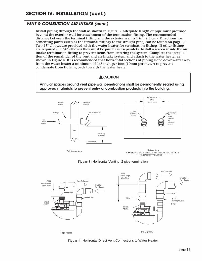
Install piping through the wall as shown in Figure 3. Adequate length of pipe must protrudebeyond the exterior wall for attachment of the termination fitting. The recommendeddistance between the terminal fitting and the exterior wall is 1 in. (2.5 cm). Directions forcementing joints (such as the terminal fittings to the straight pipe) can be found on page 24.Two 45° elbows are provided with the water heater for termination fittings. If other fittingsare required (i.e. 90° elbows) they must be purchased separately. Install a screen inside the airintake termination fitting to prevent items from entering the system. Complete the installa-tion of the remainder of the vent and air intake system and attach to the water heater asshown in Figure 4. It is recommended that horizontal sections of piping slope downward awayfrom the water heater a minimum of 1/8 inch per foot (10mm per meter) to preventcondensate from flowing back towards the water heater.
CAUTION
Annular spaces around vent pipe wall penetrations shall be permanently sealed usingapproved materials to prevent entry of combustion products into the building.
Page 15
SECTION IV: INSTALLATION (cont.)
VENT & COMBUSTION AIR INTAKE (cont.)
Vent Terminal
From Water
Heater
Wall
Outside of Building
Inside of Building
Vent Pipe
12" (30 cm) or greater
Ground Level
Wall Section View Outside ViewCAUTION - NEVER INSTALL AIR INTAKE ABOVE VENT
(EXHAUST) TERMINAL
12" (30 cm)MIN.
(center-to-center)
Vent (Exhaust) Terminal
Combustion Air Intake Terminal(w/ protectivescreen)
Figure 3: Horizontal Venting, 2-pipe termination
NO
BEND ±
Before Elbow
4" MINVertical Length
Vent (To Outside)
Air Intake (From Outside)
3" Pipe
3" Pipe
Air Intake(From Outside)
Vent (To Outside)
3" pipe systems 4" pipe systems
ExhaustAdapter
Before Elbow
4" MINVertical Length
3" Pipe
3" Pipe 4" x 3" Reducing Coupling
4" Pipe
ExhaustAdapter
Figure 4: Horizontal Direct Vent Connections to Water Heater

Page 16
Horizontal Venting, Power Vent 1-pipe termination
This water heater may be vented horizontally (through a sidewall) with a one-pipetermination. In this case, the water heater will be utilizing air from inside the building forcombustion air. A single hole through the exterior of the building is required for the ventpipe.
Note: If air from inside the building will be used for combustion air, the require-ments in Section III, “Unconfined Space” must be met.
All clearances must comply with local codes or the latest edition of NFPA 54/ANSI Z223.1or CSA B149. See Figure 5 and Table 9 for vent terminal clearances.
SECTION IV: INSTALLATION (cont.)
VENT & COMBUSTION AIR INTAKE (cont.)
Figure 5: Terminal Clearances
Page 17
SECTION IV: INSTALLATION (cont.)
VENT & COMBUSTION AIR INTAKE (cont.)
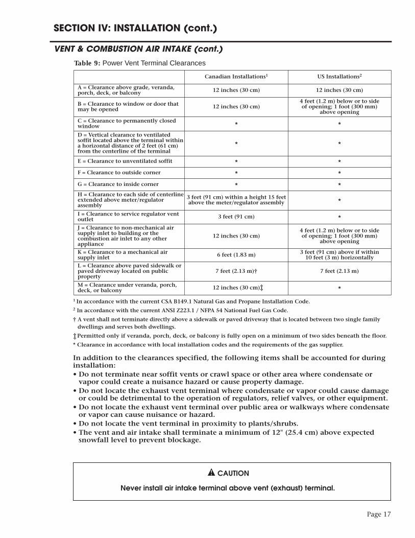
Table 9: Power Vent Terminal ClearancesCanadian Installations1 US Installations2
A = Clearance above grade, veranda,porch, deck, or balcony 12 inches (30 cm) 12 inches (30 cm)
B = Clearance to window or door thatmay be opened 12 inches (30 cm)
4 feet (1.2 m) below or to side of opening; 1 foot (300 mm)
above opening
C = Clearance to permanently closedwindow * *D = Vertical clearance to ventilatedsoffit located above the terminal withina horizontal distance of 2 feet (61 cm)from the centerline of the terminal
* *
E = Clearance to unventilated soffit * *F = Clearance to outside corner * *G = Clearance to inside corner * *H = Clearance to each side of centerlineextended above meter/regulatorassembly
3 feet (91 cm) within a height 15 feetabove the meter/regulator assembly *
I = Clearance to service regulator ventoutlet 3 feet (91 cm) *J = Clearance to non-mechanical airsupply inlet to building or thecombustion air inlet to any otherappliance
12 inches (30 cm)4 feet (1.2 m) below or to side of opening; 1 foot (300 mm)
above opening
K = Clearance to a mechanical airsupply inlet 6 feet (1.83 m) 3 feet (91 cm) above if within
10 feet (3 m) horizontallyL = Clearance above paved sidewalk orpaved driveway located on publicproperty
7 feet (2.13 m)† 7 feet (2.13 m)
M = Clearance under veranda, porch,deck, or balcony 12 inches (30 cm) *
1 In accordance with the current CSA B149.1 Natural Gas and Propane Installation Code.2 In accordance with the current ANSI Z223.1 / NFPA 54 National Fuel Gas Code.
† A vent shall not terminate directly above a sidewalk or paved driveway that is located between two single familydwellings and serves both dwellings.
Permitted only if veranda, porch, deck, or balcony is fully open on a minimum of two sides beneath the floor.
* Clearance in accordance with local installation codes and the requirements of the gas supplier.
In addition to the clearances specified, the following items shall be accounted for duringinstallation:• Do not terminate near soffit vents or crawl space or other area where condensate orvapor could create a nuisance hazard or cause property damage.
• Do not locate the exhaust vent terminal where condensate or vapor could cause damageor could be detrimental to the operation of regulators, relief valves, or other equipment.
• Do not locate the exhaust vent terminal over public area or walkways where condensateor vapor can cause nuisance or hazard.
• Do not locate the vent terminal in proximity to plants/shrubs.• The vent and air intake shall terminate a minimum of 12" (25.4 cm) above expectedsnowfall level to prevent blockage.
CAUTION
Never install air intake terminal above vent (exhaust) terminal.
††
††

Page 18
Install piping through the wall as shown in Figure 6. Adequate length of pipe must protrudebeyond the exterior wall for attachment of the termination fitting. The recommendeddistance between the terminal fitting and the exterior wall is 1 in. (2.5 cm). Directions forcementing joints (such as the terminal fittings to the straight pipe) can be found on page 24.Two 45° elbows are provided with the water heater for termination fittings. If other fittingsare required (i.e. 90° elbows) they must be purchased separately. Install a screen inside the airintake termination fitting to prevent items from entering the system. Complete the installa-tion of the remainder of the vent and air intake system and attach to the water heater asshown in Figure 7. It is recommended that horizontal sections of piping slope downward awayfrom the water heater a minimum of 1/8 inch per foot (10 mm per meter) to preventcondensate from flowing back towards the water heater.
CAUTION
Annular spaces around vent pipe wall penetrations shall be permanently sealed usingapproved materials to prevent entry of combustion products into the building.
SECTION IV: INSTALLATION (cont.)
VENT & COMBUSTION AIR INTAKE (cont.)
Vent Terminal
From Water
Heater
Wall
Outside of Building
Inside of Building
Vent Pipe
12" (30 cm) or greater
Ground Level
Wall Section View
Figure 6: Horizontal Venting, 1-pipe termination
NO
BEND ±
Before Elbow
4" MINVertical Length
Vent (To Outside)
Air Intake (From Inside)
3" Pipe
3" Pipe
Air Intake(From Inside)
Vent (To Outside)
3" pipe systems 4" pipe systems
ExhaustAdapter
Fitting w/ protective screen
Fitting w/ protective screen
Before Elbow
4" MINVertical Length
3" Pipe
3" Pipe
4" x 3" Reducing Coupling
4" Pipe
ExhaustAdapter
Figure 7: Horizontal Power Vent Connections to Water Heater
Page 19
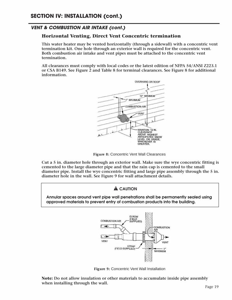
Horizontal Venting, Direct Vent Concentric termination
This water heater may be vented horizontally (through a sidewall) with a concentric venttermination kit. One hole through an exterior wall is required for the concentric vent.Both combustion air intake and vent pipes must be attached to the concentric venttermination.
All clearances must comply with local codes or the latest edition of NFPA 54/ANSI Z223.1or CSA B149. See Figure 2 and Table 8 for terminal clearances. See Figure 8 for additionalinformation.
Cut a 5 in. diameter hole through an exterior wall. Make sure the wye concentric fitting iscemented to the large diameter pipe and that the rain cap is cemented to the smalldiameter pipe. Install the wye concentric fitting and large pipe assembly through the 5 in.diameter hole in the wall. See Figure 9 for wall attachment details.
CAUTION
Annular spaces around vent pipe wall penetrations shall be permanently sealed usingapproved materials to prevent entry of combustion products into the building.
Note: Do not allow insulation or other materials to accumulate inside pipe assemblywhen installing through the wall.
SECTION IV: INSTALLATION (cont.)
VENT & COMBUSTION AIR INTAKE (cont.)
Figure 8: Concentric Vent Wall Clearances
Figure 9: Concentric Vent Wall Installation
Page 20
Install the rain cap and small pipe assembly into the wye concentric fitting and large pipeassembly. Ensure small diameter pipe is bottomed and cemented in wye concentric fitting.Complete indoor piping runs and connect piping to the water heater. See Figure 4, 3" pipesystems, for connection details. It is recommended that horizontal sections of piping slopedownward away from the water heater a minimum of 1/8 inch per foot (10 mm per meter) toprevent condensate from flowing back towards the water heater. Piping must be sufficientlysupported. At minimum, it is recommended that a support is placed along the vent or airintake piping every 4 feet. For additional information, see installation instructions suppliedwith concentric vent kit.
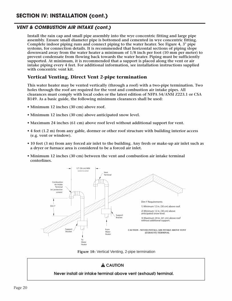
Vertical Venting, Direct Vent 2-pipe termination
This water heater may be vented vertically (through a roof) with a two-pipe termination. Twoholes through the roof are required for the vent and combustion air intake pipes. Allclearances must comply with local codes or the latest edition of NFPA 54/ANSI Z223.1 or CSAB149. As a basic guide, the following minimum clearances shall be used:
• Minimum 12 inches (30 cm) above roof.
• Minimum 12 inches (30 cm) above anticipated snow level.
• Maximum 24 inches (61 cm) above roof level without additional support for vent.
• 4 feet (1.2 m) from any gable, dormer or other roof structure with building interior access(e.g. vent or window).
• 10 feet (3 m) from any forced air inlet to the building. Any fresh or make-up air inlet such asa dryer or furnace area is considered to be a forced air inlet.
• Minimum 12 inches (30 cm) between the vent and combustion air intake terminalcenterlines.
CAUTION
Never install air intake terminal above vent (exhaust) terminal.
SECTION IV: INSTALLATION (cont.)
VENT & COMBUSTION AIR INTAKE (cont.)
Figure 10: Vertical Venting, 2-pipe termination
VentTerminal
Combustion Air Intake Terminal
(w/ protective screen)
FromWaterHeater
ToWaterHeater
Dim Y
Dim Y Requirements
1) Minimum 12 in. (30 cm) above roof.
2) Minimum 12 in. (30 cm) above anticipated snow level.
3) Maximum 24 in. (61 cm) above roof without additional support.
SupportBracket
SupportBracket
CAUTION - NEVER INSTALL AIR INTAKE ABOVE VENT (EXHAUST) TERMINAL
12" (30 cm) MIN (center-to-center)

Page 21
Install piping through the roof as shown in Figure 10. Adequate length of pipe must protrudebeyond the exterior of the roof (see dimension Y). Directions for cementing joints (such as theterminal fittings to the straight pipe) can be found on page 24. Two 90° elbows arerecommended for the intake and exhaust terminations to reduce the risk of rain, snow, orforeign objects entering the system. Install a screen inside the air intake termination fitting aswell. Complete the installation of the remainder of the vent and air intake system and attach tothe water heater. Piping must be sufficiently supported. At minimum, it is recommended that asupport is placed along the vent or air intake piping every 4 feet. For vertical venting, thecondensate drain kit must be installed to the exhaust adapter.
CAUTION
Annular spaces around vent pipe wall penetrations shall be permanently sealed usingapproved materials to prevent entry of combustion products into the building.
Vertical Venting, Power Vent 1-pipe termination
This water heater may be vented vertically (through a roof) with a one-pipe termination.In this case, the water heater will be utilizing air from inside the building for combustionair. A single hole through the roof of the building is required for the vent pipe.
Note: If air from inside the building will be used for combustion air, the require-ments in Section III, “Unconfined Space” must be met.
All clearances must comply with local codes or the latest edition of NFPA 54/ANSI Z223.1or CSA B149. As a basic guide, the following minimum clearances shall be used:
• Minimum 12 inches (30 cm) above roof.
• Minimum 12 inches (30 cm) above anticipated snow level.
• Maximum 24 inches (61 cm) above roof level without additional support for vent.
• 4 feet (1.2 m) from any gable, dormer or other roof structure with building interioraccess (e.g. vent or window).
• 10 feet (3 m) from any forced air inlet to the building. Any fresh or make-up air inletsuch as a dryer or furnace area is considered to be a forced air inlet.
SECTION IV: INSTALLATION (cont.)
VENT & COMBUSTION AIR INTAKE (cont.)
NO
Vent (To Outside)
Air Intake (From Outside)
3" Pipe
3" Pipe
Air Intake(From Outside)
Vent (To Outside)
3" pipe systems 4" pipe systems
ExhaustAdapter
CondensateKitConnection
3" Pipe
3" Pipe 4" x 3" Reducing Coupling
4" Pipe
ExhaustAdapter
CondensateKitConnection
Figure 11: Vertical Direct Vent Connections to Water Heater

Page 22
Install piping through the roof as shown in Figure 12. Adequate length of pipe must protrudebeyond the exterior of the roof (see dimension Y). Directions for cementing joints (such as theterminal fittings to the straight pipe) can be found on page 24. Two 90° elbows arerecommended for the exhaust termination to reduce the risk of rain, snow, or foreign objectsentering the system. Install a screen inside the air intake termination fitting as well. Completethe installation of the remainder of the vent system and attach to the water heater. Pipingmust be sufficiently supported. At minimum, it is recommended that a support is placed alongthe vent piping every 4 feet. For vertical venting, the condensate drain kit must be installed tothe exhaust adapter.
SECTION IV: INSTALLATION (cont.)
VENT & COMBUSTION AIR INTAKE (cont.)
VentTerminal
FromWaterHeater
Dim Y
Dim Y Requirements
1) Minimum 12 in. (30 cm) above roof (US). Minimum 18 in. (46 cm) above roof (Canada).
2) Minimum 12 in. (30 cm) above anticipated snow level (US). Minimum 18 in. (46 cm) above anticipated snow level (Canada).
3) Maximum 24 in. (61 cm) above roof without additional support.
SupportBracket
Figure 12: Vertical Venting, 1-pipe termination
NO
BEND ±
Vent (To Outside)
Air Intake (From Inside)
3" Pipe
3" Pipe
Air Intake(From Inside)
Vent (To Outside)
3" pipe systems 4" pipe systems
ExhaustAdapter
Fitting w/ protective mesh screen
Fitting w/ protective screen
CondensateKit Connection
3" Pipe
3" Pipe
4" x 3" Reducing Coupling
4" Pipe
ExhaustAdapter
CondensateKitConnection
Figure 13: Vertical Power Vent Connections to Water Heater
Page 23
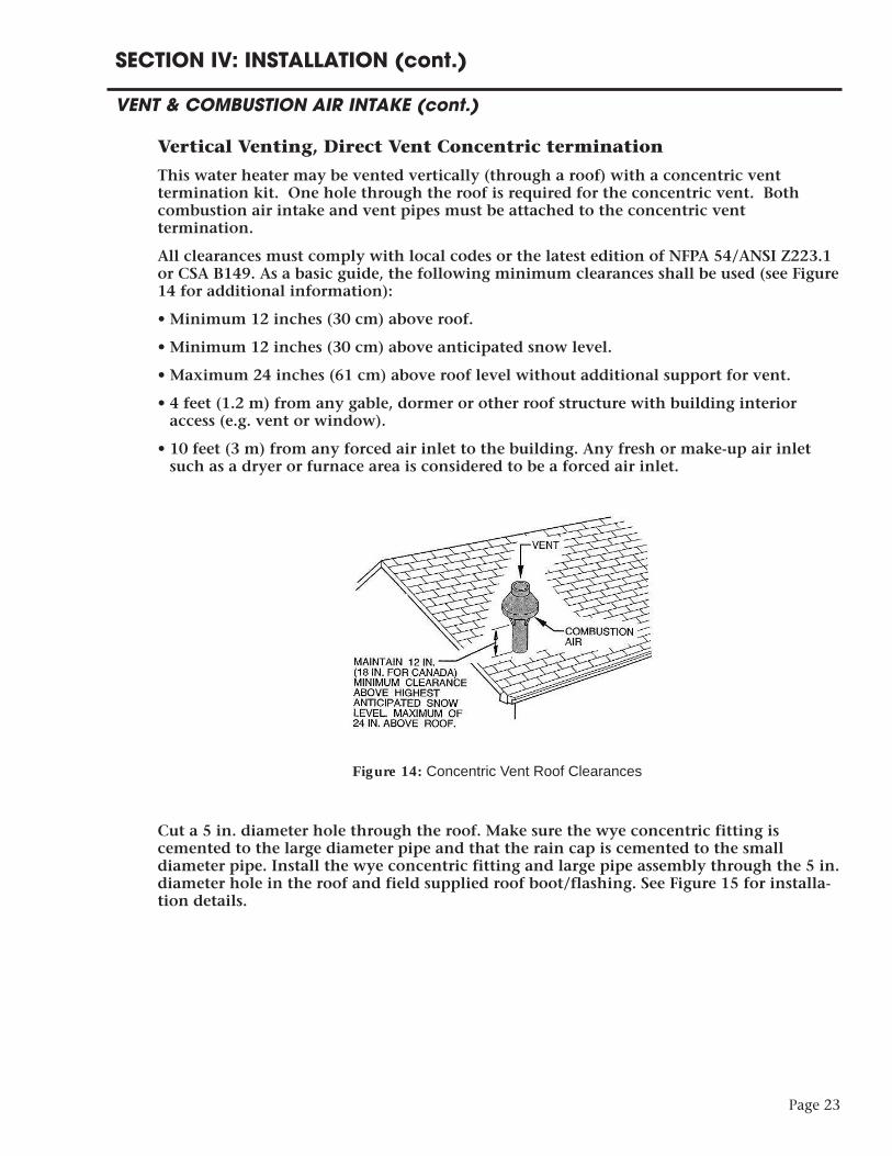
Vertical Venting, Direct Vent Concentric termination
This water heater may be vented vertically (through a roof) with a concentric venttermination kit. One hole through the roof is required for the concentric vent. Bothcombustion air intake and vent pipes must be attached to the concentric venttermination.
All clearances must comply with local codes or the latest edition of NFPA 54/ANSI Z223.1or CSA B149. As a basic guide, the following minimum clearances shall be used (see Figure14 for additional information):
• Minimum 12 inches (30 cm) above roof.
• Minimum 12 inches (30 cm) above anticipated snow level.
• Maximum 24 inches (61 cm) above roof level without additional support for vent.
• 4 feet (1.2 m) from any gable, dormer or other roof structure with building interioraccess (e.g. vent or window).
• 10 feet (3 m) from any forced air inlet to the building. Any fresh or make-up air inletsuch as a dryer or furnace area is considered to be a forced air inlet.
Cut a 5 in. diameter hole through the roof. Make sure the wye concentric fitting iscemented to the large diameter pipe and that the rain cap is cemented to the smalldiameter pipe. Install the wye concentric fitting and large pipe assembly through the 5 in.diameter hole in the roof and field supplied roof boot/flashing. See Figure 15 for installa-tion details.
SECTION IV: INSTALLATION (cont.)
VENT & COMBUSTION AIR INTAKE (cont.)
Figure 14: Concentric Vent Roof Clearances

Page 24
SECTION IV: INSTALLATION (cont.)
VENT & COMBUSTION AIR INTAKE (cont.)
Note: Do not allow insulation or other materials toaccumulate inside pipe assembly when installingthrough the roof.
Install the rain cap and small pipe assembly intothe wye concentric fitting and large pipe assembly.Ensure small diameter pipe is bottomed andcemented in wye concentric fitting. Completeindoor piping runs and connect piping to thewater heater. See Figure 11, 3" pipe systems, forconnection details. Piping must be sufficientlysupported. At minimum, it is recommended that a support is placed along the vent or air intakepiping every 4 feet. For additional information, see installation instructions supplied withconcentric vent kit. For vertical venting, thecondensate drain kit must be installed to theexhaust adapter.
Assembling Vent and Air Intake Joints
WARNING
Cements and primers are highly flammable. Assemble joints in an adequatelyventilated area away from heat sources or open flames. Do not smoke. Read cautions and warnings on material containers.
CAUTION
DO NOT use cement that is lumpy or thick. DO NOT thin cement.
Connections (i.e. joints) between plastic pipe and fittings must be properly sealed. Thisrequires that an appropriate primer (cleaner) and cement (solvent) are used for the type ofmaterial (PVC, CPVC, ABS) that is used in the venting system. For PVC use ASTM D2564grade cement, for CPVC use ASTM F493 grade cement, and for ABS use ASTM D2235 gradecement. The following steps should be taken when connecting plastic pipe and fittings:
• Cut pipe square with hand saw and remove burrs from inside and outside edges.
• Clean fitting socket and pipe joint area of all dirt, grease, or moisture.
• Check dry fit. Pipe should easily go 1/3 of the way into the fitting socket.
• Liberally apply primer to inside of fitting socket and pipe joint area.
Figure 15: Concentric Vent Roof Installation

• Over the wet primer, apply a medium coat of cement to the fitting socket and pipe jointarea.
• Insert pipe into fitting with a slight twisting motion. Ensure that the pipe is bottomedinto the fitting.
• Hold pipe and fitting for 30 seconds to prevent push off.
• Wipe off excess cement. Cure time may be up to 2 hours for Ø3" pipe at 60°F. Longercure time is required for larger diameter pipe and/or lower temperatures.
Note: The vent and combustion air intake pipe/fittings must overlap a minimumof 1/2 inch (1.3 cm) at each joint. DO NOT drill or punch holes in the plastic pipeor fittings.
Condensate Drain Kit
When downward sloping of the vent system is not possible or a vertical vent arrangementis used, the condensate drain kit must be installed. Follow these steps to properly installthe kit:
• Turn off all electrical power to the water heater.
• Remove the yellow cap from the exhaust adapter.
• Insert one end of the 3/8" OD plastic tube into the fitting on the exhaust adapter. Thereshould be a tight fit between the tube and the fitting. If the connection is not tight,apply adhesive aluminum tape around the connection to secure.
• Form a trap by looping a portion of the plastic tube into approximately a 6" diametercircle. With respect to the water heater, form the loop such that it can be mounted onthe upper 1/3 of the heater.
• Use the supplied loop clamps and screws to secure the tubing to the side of the waterheater and hold the loop trap in place.
• The condensate drain tube must terminate over a proper floor drain or collectionbucket. If necessary, add additional tubing to reach a floor drain.
• Prime the loop trap with water prior to resuming operation of the water heater.Disconnect the end of the tube that was connected to the exhaust adapter. With the freeend above the loop trap, pour water into the tube until the loop is filled halfway.
• Reconnect the free end to the exhaust adapter fitting and turn on electrical power to thewater heater.
DANGER
Failure to prime the condensate drain loop with water will result in combustion gas(which may contain carbon monoxide) entering the room. To avoid the risk of asphyxiation from carbon monoxide, never operate the water heater unless thecondensate drain loop is sealed with water.
An example of this installation is shown in Figure 17.
Page 25
SECTION IV: INSTALLATION (cont.)
VENT & COMBUSTION AIR INTAKE (cont.)

Page 26
SECTION IV: INSTALLATION (cont.)
WATER CONNECTIONS
CAUTION
This water heater incorporates fittings that contain a nonmetallic lining. DO NOT applyheat to these fittings when making sweat connections to the heater. Sweat tubing to an adapter before securing adapter to any fittings on water heaters.
ALL PIPING SHOULD CONFORM TO LOCAL CODES AND ORDINANCES. It is highlyrecommended that unions and shut-off valves are installed at the potable water connectionsto allow for isolation and/or movement during service. All piping should be adequatelyinsulated with an approved material to minimize heat loss.
POTABLE WATER CONNECTIONS
THE WATER HEATER MUST BE FILLED WITH WATER BEFORE LIGHTING THEBURNER.
1) Close the main water supply valve before continuing with the installation. After the mainwater supply is shut-off, relieve the water line pressure by opening a faucet. Once the pressurehas been relieved, close the faucet. The “Cold” and “Hot” potable water connections arelabeled on the water heater. Install a union and shut-off valve at both potable waterconnections. All piping should be 3/4" diameter new copper or larger. A tempering valve oranti-scald valve should be installed at the potable water outlet and used according to themanufacturer’s specifications to prevent scalding.
2) If a backflow preventer, check valve, or pressure regulating valve is required in the coldwater supply, a properly sized expansion tank must be installed to control thermal expansion.Do not operate the water heater in a closed system without installing a thermal expansiontank. Follow the expansion tank manufacturer’s recommendations when selecting a tank foryour system.
3) Following installation of the water lines, open the main water supply valve and fill thewater heater. Open several hot water faucets to relieve air from the system. After water isflowing through the faucets and the system is void of air, close the faucets and check for waterleaks in the system.
Note: Do not try to heat hard water as this will drastically reduce heater life. Install a watersoftener or other scale reducing water treatment system if the water heater is being installed ina hard water area (water hardness higher than seven grains).
SOLAR CONNECTIONS
CAUTION
Temperature of the primary heat source medium (from solar collector) shall not exceed200°F.
The outlet of the solar collector should be connected to the water heater at the “FROMSOLAR” fitting. The fitting labeled “TO SOLAR” should be connected to the solar returnpiping. It is recommended to install a union and shut-off valve at each solar connection. Allpipe and fittings between the solar system and water heater should be 3/4” diameter or larger.Reference the solar collector installation instructions or contact the manufacturer for propercomponents and solar loop system design.

Page 27
SECTION IV: INSTALLATION (cont.)
GAS CONNECTIONS
CAUTION Do not use this water heater with any gas other than the type listed on the rating label.
Check the rating label on the front of the water heater and make sure the gas to beused matches the gas stated on the rating label. Consult your local gas company orBock Water Heaters with any questions.
A manual valve, union, and a sediment trap shall be provided in front of the gas valve. All gaspiping must conform to local codes and/or the National Fuel Gas Code ANSI 223.1/NFPA 54 orCSA B149.1.
Note: When sizing the gas piping to the heater, make sure that the pressure at the valve is sufficient when all other appliances are operating. Undersized gas piping will reduce waterheater performance and life as well as result in nuisance lockouts. Also verify that the gasservice and meter are sized properly for the load.
Gas piping should be carried oversize, i.e.: 3⁄4 inch or 1 inch or larger for 1⁄2 inch valve to within 2 feet of the valve itself. This sustains pressure at the valve during start-up to preventflashbacks caused by momentary pressure loss. For natural gas, 5" W.C. pressure must bemaintained upstream of the gas valve during operation. For LP gas, a minimum of 11" W.C.must be maintained upstream of the gas valve. A 1⁄8 inch NPT pipe connection should beinstalled upstream of the manual shut-off valve to check incoming gas pressure.
During pressure testing of the gas supply piping, close the manual gas shut-off valve to thewater heater. Test pressure shall not exceed 1⁄2 PSIG (14" W.C). The gas valve is only rated for 1⁄2 PSIG. To test at pressure greater than 1⁄2 PSIG, close the manual shut-off valve anddisconnect the gas operating valve.
Turn on gas and inspect piping for leaks by "painting" each joint with a soapy water solutionand check for bubbles. Make sure that excess solution does not enter the control's plastichousing and all wiring remains dry.
WARNING
DO NOT use an open flame to check for leaks. Serious injury or death could result fromfire or explosion.
The pipe thread compound that is used on gas piping must be of the type resistant topropane gas. Do not use teflon tape on gas piping.
The recommended gas piping to the water heater control is shown in Figure 16. Figure 17 gives an overview of all field piping connections.
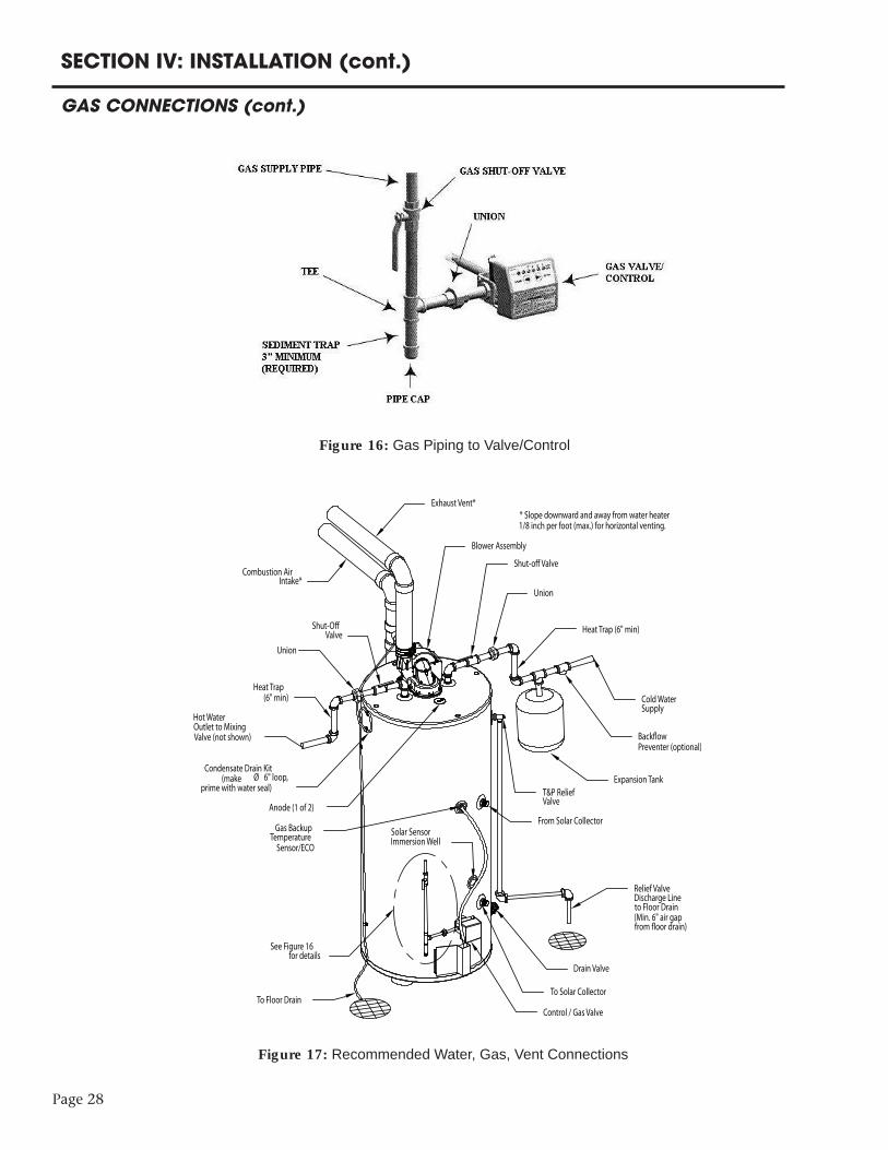
Page 28
SECTION IV: INSTALLATION (cont.)
GAS CONNECTIONS (cont.)
Figure 16: Gas Piping to Valve/Control
Cold Water Supply
Back!ow Preventer (optional)
Expansion TankT&P ReliefValve
Relief ValveDischarge Lineto Floor Drain(Min. 6" air gap from !oor drain)
Drain Valve
Control / Gas Valve
Heat Trap (6" min)
Union
Shut-o# Valve
Blower Assembly
Exhaust Vent** Slope downward and away from water heater 1/8 inch per foot (max.) for horizontal venting.
Combustion AirIntake*
Shut-O# Valve
Union
Heat Trap(6" min)
Hot Water Outlet to MixingValve (not shown)
Condensate Drain Kit(make Ø 6" loop,
prime with water seal)
Anode (1 of 2)
See Figure 16 for details
To Floor Drain
Gas BackupTemperature
Sensor/ECO
Solar SensorImmersion Well
From Solar Collector
To Solar Collector
Figure 17: Recommended Water, Gas, Vent Connections

Page 29
All electrical wiring and connections must be in accordance with local codes. In the absenceof local codes, wiring must conform to the National Electric Code ANSI/NFPA No. 70 or theCanadian Electrical Code C22.1. This water heater must be electrically grounded. Electricalpower should be supplied through a fused disconnect switch located near the water heater.Where local codes permit, use the supplied power cord for field connection. A groundingreceptacle is required. If local codes do not permit the used of the supplied cord, remove thepower cord from the blower assembly and replace with suitable power supply (120V, 60 Hz)wiring and connections. The water heater draws less than 5 amps (maximum). Check forproper polarity at the main power connection prior to operating the water heater.
The factory installed immersion well is designed to accommodate insertion of a thermistor.The solar system controller and thermistor is not supplied with this water heater.
CAUTION
Turn off or disconnect the electrical power supply to the water heater before servicing.Label all wires prior to disconnection when servicing controls. Wiring errors can causeimproper and dangerous operation. Verify proper operation after servicing.
A component and schematic wiring diagram is shown in Figure 18.
SECTION IV: INSTALLATION (cont.)
WIRING
Figure 18: Component and Schematic Wiring Diagrams
Page 30
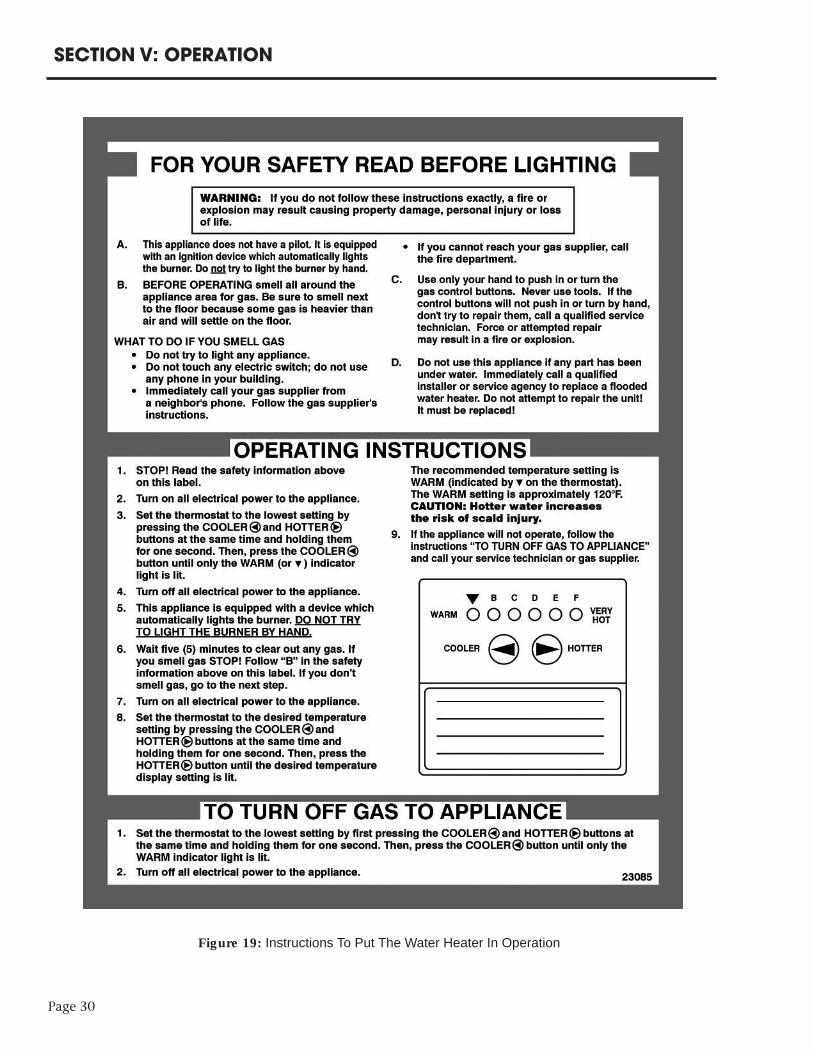
SECTION V: OPERATION
Figure 19: Instructions To Put The Water Heater In Operation

SECTION V: OPERATION (cont.)
SEQUENCE OF OPERATIONAPPLY POWER TO
APPLIANCE
IS FIELD WIRINGCORRECT?
DISPLAY ERROR CODE1 OR 2
NO
YES
REQUESTFOR HEATPRESENT?
NO
ISPRESSURE SWITCH
PROVEN OPEN WITHIN5 SECONDS?
YES
NO
COMBUSTIONBLOWER ON
YES
ISPRESSURE SWITCHPROVEN CLOSED
WITHIN 5SECONDS?
NO
WAIT FOR PRESSURESWITCH TO OPENDISPLAY ERROR
NUMBER3
WAIT FOR PRESSURESWITCH TO CLOSE
DISPLAY ERRORNUMBER 4
PREPURGE
ISIGNITOROKAY?
TURN OFF INDUCERDISPLAY ERROR CODE
NUMBER 5
NO
IGNITOR ON FORWARM-UP TIME
YES
YESMAIN VALVE OPENS
MAINBURNER LIGHTSAND IS SENSEDDURING TRIAL
FORIGNITION
IGNITOR TURNS OFF
YES
NO
ISFLAME SENSE
LOST?
ISREQUEST FOR HEAT
SATISFIED?
MAIN VALVE OFF
COMBUSTIONBLOWER OFF AFTERPOST-PURGE DELAY
MAIN VALVE CLOSESLESS
THAN 3 TRIES FOR IGNITION?
MAIN VALVE CLOSESLOST
LESS THAN 3TIMES?
YES
YES
TURN OFF INDUCERAFTER POST-PURGEDISPLAY ERROR 6
ONE HOUR AUTOLOCKOUT RESET
DELAY
NO
NONO
YES
YES
NO
ISPRESSURE SWITCH
PROVEN OPEN WITHIN5 SECONDS?
WAIT FOR PRESSURESWITCH TO OPENDISPLAY ERROR
NUMBER3
COMBUSTIONBLOWER ON
ISPRESSURE SWITCHPROVEN CLOSED
WITHIN 5SECONDS?
WAIT FOR PRESSURESWITCH TO CLOSE
DISPLAY ERRORNUMBER 4
INTERPURGE
COMBUSTIONBLOWER OFF
YES
NO
NO
YES
YES
Figure 20: Sequence of Operation
Figure 20 gives a step-by-step description ofthe sequence of operations for the gas-firedwater heater. See Troubleshooting section ofthis manual for solutions to error codes.
Page 31
Page 32
SECTION V: OPERATION (cont.)
HEATING OPERATIONSCondition 1: The minimum temperature difference (for heat transfer) between the potablewater at the bottom of the tank and the solar collector is sensed by the solar controller. Inaddition, the tank temperature is below the maximum tank temperature setpoint (on solarcontrol). Action 1: The solar controller energizes a pump to flow fluid through the solar collector andheat exchanger. Heat is transferred to the potable water until the temperature difference isreduced to a desired value or the maximum tank temperature has been reached.
Condition 2: The gas backup thermostat senses that the potable water temperature in theupper area of the tank drops below the thermostat set-point. Action 2: The gas burner is on and heats the potable water to the set-point temperature, atwhich point the gas valve closes.
INSPECT THE INSTALLATION AND ADJUST THE CONTROLSFor natural gas, the manifold pressure is preset at 4.0” w.c. and the acceptable inlet pressure isin the range of 5-14” w.c. For propane gas, the manifold pressure is preset at 10.0” w.c. and theacceptable inlet pressure is in the range of 11-14” w.c. See the “Pre-Installation” section of thismanual for information on clearances, air supply, and venting.
The thermostat has been adjusted to 120°F at the factory. Wait until thermostat has shut offgas to the main burner. Wait 30 seconds following shut-off of gas, then set thermostat to thehighest temperature. The main burner should relight. Set thermostat to the lowesttemperature; the main burner should go out. The thermostat should be adjusted to theminimum setting that will meet the hot water needs of the homeowner or commercialapplication.
CAUTION There is a scald potential if the thermostat is set too high. The recommended
temperature setting for normal residential use is 120°F. If higher temperature settings areneeded for combined appliance applications or commercial use, an automatictempering valve must be installed on all domestic hot water lines.
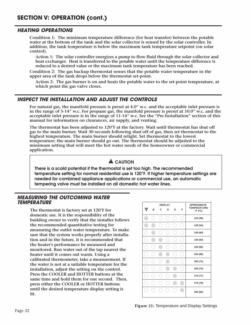
MEASURING THE OUTCOMING WATERTEMPERATURE
The thermostat is factory set at 120°F fordomestic use. It is the responsibility of thebuilding owner to verify that the installer followsthe recommended quantitative testing formeasuring the outlet water temperature. To makesure that the system works properly after installa-tion and in the future, it is recommended thatthe heater’s performance be measured andmonitored. Run water out of the tap nearest theheater until it comes out warm. Using acalibrated thermometer, take a measurement. Ifthe water is not at a suitable temperature for theinstallation, adjust the setting on the control.Press the COOLER and HOTTER buttons at thesame time and hold them for one second. Then,press either the COOLER or HOTTER buttonsuntil the desired temperature display setting islit.
APPROXIMATETEMPERATURE
( C)o
DISPLAY
120 (49)
130 (54)
140 (60)
145 (63)
150 (66)
155 (68)
160 (71)
165 (74)
170 (77)
175 (79)
180 (82)
B C D E F Fo
Figure 21: Temperature and Display Settings

Page 33
SECTION V: OPERATION (cont.)
MEASURING THE OUTCOMING WATER TEMPERATURE (cont.)This log (or a similar one) should be filled out as follows:
SECTION VI: MAINTENANCE
NOTICE TO THE OWNER: If you are having a mechanical problem with your water heater,contact your service company or installer.
WATER PIPINGOn an annual basis, all piping should be checked for leakage at joints, shut-off valves, and unions.
T&P RELIEF VALVEOn an annual basis, the temperature and pressure relief valve should be checked for properoperation. First, attach a drain line to the valve to direct the water discharge to an open drain.This is very important because the temperature of the discharge could be very hot. Second,lift the lever at the end of the valve several times. The valve should operate freely and returnto its original position properly. If water does not flow out of the valve, remove and inspectfor corrosion or obstructions. Replace with a new valve if necessary. Do not repair the faultyvalve as this may cause improper operation.
ANODE RODSAnode rods should be inspected twice in the first year and at least yearly once a time intervalfor inspection has been developed. It is recommended to check the rod(s) six months after theheater is installed. If the anode rod had reduced in size by two-thirds of its original diameterof 3/4” or shows signs of pitting, it is time for replacement. Take the following steps whenchanging the anode rod(s):
1. Shut off water supply.2. Open any faucet to relieve tank pressure.3. Remove caps on water heater top; push insulation aside.4. Use a 1 1/16” six-sided socket wrench and a breaker bar. Snap hard to break the anode rod seal.5. Remove rod(s) and replace with new rod(s). 6. Turn water supply back on and leave faucet open until air is out of line.7. Turn faucet off and check that new rod(s) doesn’t leak.8. Snap caps back into place.
FLUSH THE TANKElements in the water such as lime and iron may accumulate in the heater. Accumulation ofthese elements can keep your water heater from operating at peak efficiency and may lead topremature tank failure. It is recommended that the tank is drained and flushed thoroughlyonce a year to prevent buildup.
Date Time Person running test Set temp °F Outlet temp °F
Page 34
SECTION VI: MAINTENANCE (cont.)
SOLAR CONTROLLER AND COLLECTOR PANELSThe solar controller and collector panel manufacturer may have a recommended maintenanceprocedure. Refer to the instruction manual that was received with the solar equipment.
INSPECT THE VENTING SYSTEM, FLUE, AND BURNERThe vent and combustion air intake system should be checked at least once a year for damageand blockage. Make sure all joints are secure and that the system is properly supported.Inspect the outdoor terminals to make sure they are free of obstructions.
CAUTION
For your safety, removal of the blower assembly, cleaning of the flue, and removal of theburner must be performed by a qualified service technician. If the burner is removed it mustbe leak tested following reinstallation before normal water heater operation is resumed. Allparts must be replaced to their original position prior to operating the water heater.
The water heater flue should be inspected periodically to be sure it is clean. In order to inspectthe flue, the blower assembly and flue baffle must be removed. Before removing the blowerassembly make sure the water heater is disconnected from the main power supplyand the gas supply to the water heater is shut off.Wait at least 5 minutes to allow theflue to cool. Remove the flue baffle and clean the flue with a flexible wire brush. Slide thebrush down the flue at the free end of each row of fins. This should knock any rust flakes intothe combustion chamber for removal.
WARNING
If the flue is blocked with soot this indicates serious combustion problems related to thebuilding and/or installation. These must be addressed before placing the water heaterback in operation.
Vacuum any rust flakes or sediment collected in the combustion chamber before restarting theheater. Remove the outer and inner access doors. The inner access door is mounted to the tankskirt with screws. Disconnect the burner tube and wire harness from the gas valve and removethe burner with the inner access door attached. Remove all debris from the combustionchamber. Inspect the ignitor and flame sensor. Carefully reinstall the burner. The end of theburner tube should be positioned under the burner bracket on the inner shield. Tighten theburner tube into the gas valve and reconnect the wire harness. Remount the inner door to thetank skirt, using every screw that was originally removed. The inner door must be securelymounted. Place the flue baffle back into the flue and screw the blower assembly back intoplace on the top pan (use every screw!).
Leak test the burner connection to the gas valve prior to resuming operation.
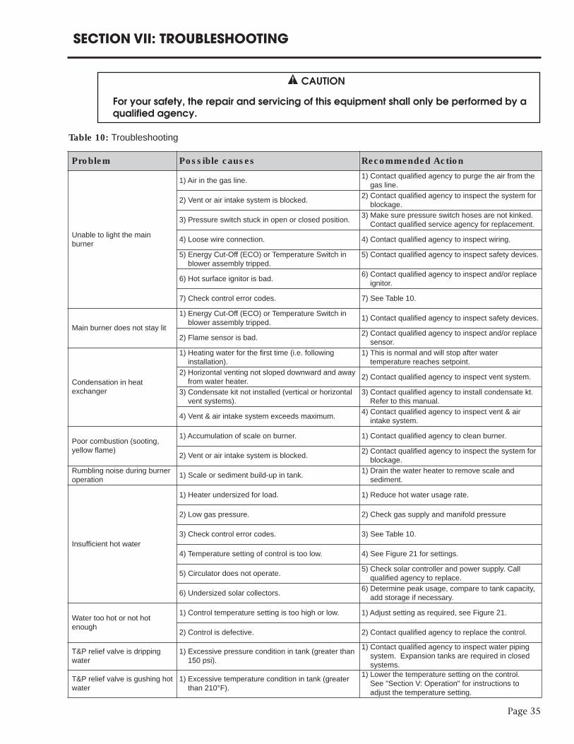
SECTION VII: TROUBLESHOOTING
CAUTION
For your safety, the repair and servicing of this equipment shall only be performed by aqualified agency.
Page 35
Table 10: Troubleshooting
Problem Possible causes Recommended Action
Unable to light the main burner
1) Air in the gas line. 1) Contact qualified agency to purge the air from thegas line.
2) Vent or air intake system is blocked. 2) Contact qualified agency to inspect the system forblockage.
3) Pressure switch stuck in open or closed position. 3) Make sure pressure switch hoses are not kinked.Contact qualified service agency for replacement.
4) Loose wire connection. 4) Contact qualified agency to inspect wiring.
5) Energy Cut-Off (ECO) or Temperature Switch inblower assembly tripped.
5) Contact qualified agency to inspect safety devices.
6) Hot surface ignitor is bad. 6) Contact qualified agency to inspect and/or replaceignitor.
7) Check control error codes. 7) See Table 10.
Main burner does not stay lit1) Energy Cut-Off (ECO) or Temperature Switch inblower assembly tripped. 1) Contact qualified agency to inspect safety devices.
2) Flame sensor is bad. 2) Contact qualified agency to inspect and/or replacesensor.
Condensation in heatexchanger
1) Heating water for the first time (i.e. following installation).
1) This is normal and will stop after watertemperature reaches setpoint.
2) Horizontal venting not sloped downward and awayfrom water heater. 2) Contact qualified agency to inspect vent system.
3) Condensate kit not installed (vertical or horizontalvent systems).
3) Contact qualified agency to install condensate kt.Refer to this manual.
4) Vent & air intake system exceeds maximum. 4) Contact qualified agency to inspect vent & airintake system.
Poor combustion (sooting,yellow flame)
1) Accumulation of scale on burner. 1) Contact qualified agency to clean burner.
2) Vent or air intake system is blocked. 2) Contact qualified agency to inspect the system forblockage.
Rumbling noise during burneroperation 1) Scale or sediment build-up in tank. 1) Drain the water heater to remove scale and
sediment.
Insufficient hot water
1) Heater undersized for load. 1) Reduce hot water usage rate.
2) Low gas pressure. 2) Check gas supply and manifold pressure
3) Check control error codes. 3) See Table 10.
4) Temperature setting of control is too low. 4) See Figure 21 for settings.
5) Circulator does not operate. 5) Check solar controller and power supply. Callqualified agency to replace.
6) Undersized solar collectors. 6) Determine peak usage, compare to tank capacity,add storage if necessary.
Water too hot or not hotenough
1) Control temperature setting is too high or low. 1) Adjust setting as required, see Figure 21.
2) Control is defective. 2) Contact qualified agency to replace the control.
T&P relief valve is drippingwater
1) Excessive pressure condition in tank (greater than150 psi).
1) Contact qualified agency to inspect water pipingsystem. Expansion tanks are required in closedsystems.
T&P relief valve is gushing hotwater
1) Excessive temperature condition in tank (greaterthan 210°F).
1) Lower the temperature setting on the control. See "Section V: Operation" for instructions toadjust the temperature setting.
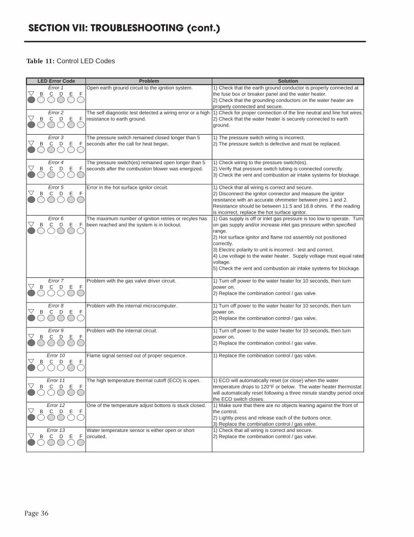
Page 36
SECTION VII: TROUBLESHOOTING (cont.)
Table 11: Control LED Codes
B C D E F
B C D E F
B C D E F
B C D E F
B C D E F
B C D E F
B C D E F
B C D E F
B C D E F
B C D E F
B C D E F
B C D E F
B C D E FError 13 Water temperature sensor is either open or short
circuited.1) Check that all wiring is correct and secure. 2) Replace the combination control / gas valve.
Error 11 The high temperature thermal cutoff (ECO) is open. 1) ECO will automatically reset (or close) when the water temperature drops to 120°F or below. The water heater thermostat will automatically reset following a three minute standby period once the ECO switch closes.
Error 12 One of the temperature adjust bottons is stuck closed. 1) Make sure that there are no objects leaning against the front of the control. 2) Lightly press and release each of the buttons once. 3) Replace the combination control / gas valve.
Error 9 Problem with the internal circuit. 1) Turn off power to the water heater for 10 seconds, then turn power on. 2) Replace the combination control / gas valve.
Error 10 Flame signal sensed out of proper sequence. 1) Replace the combination control / gas valve.
Error 7 Problem with the gas valve driver circuit. 1) Turn off power to the water heater for 10 seconds, then turn power on. 2) Replace the combination control / gas valve.
Error 8 Problem with the internal microcomputer. 1) Turn off power to the water heater for 10 seconds, then turn power on. 2) Replace the combination control / gas valve.
Error 6 1) Gas supply is off or inlet gas pressure is too low to operate. Turn on gas supply and/or increase inlet gas pressure within specified range. 2) Hot surface ignitor and flame rod assembly not positioned correctly. 3) Electric polarity to unit is incorrect - test and correct. 4) Low voltage to the water heater. Supply voltage must equal ratedvoltage. 5) Check the vent and combustion air intake systems for blockage.
The maximum number of ignition retries or recyles has been reached and the system is in lockout.
Error 4 The pressure switch(es) remained open longer than 5 seconds after the combustion blower was energized.
1) Check wiring to the pressure switch(es). 2) Verify that pressure switch tubing is connected correctly. 3) Check the vent and combustion air intake systems for blockage.
Error 5 Error in the hot surface ignitor circuit. 1) Check that all wiring is correct and secure. 2) Disconnect the ignitor connector and measure the ignitor resistance with an accurate ohmmeter between pins 1 and 2. Resistance should be between 11.5 and 18.8 ohms. If the reading is incorrect, replace the hot surface ignitor.
Error 2
Error 3
Open earth ground circuit to the ignition system. 1) Check that the earth ground conductor is properly connected at the fuse box or breaker panel and the water heater. 2) Check that the grounding conductors on the water heater are properly connected and secure.
The self diagnostic test detected a wiring error or a high resistance to earth ground.
1) Check for proper connection of the line neutral and line hot wires. 2) Check that the water heater is securely connected to earth ground.
The pressure switch remained closed longer than 5 seconds after the call for heat began.
1) The pressure switch wiring is incorrect. 2) The pressure switch is defective and must be replaced.
LED Error Code Problem SolutionError 1
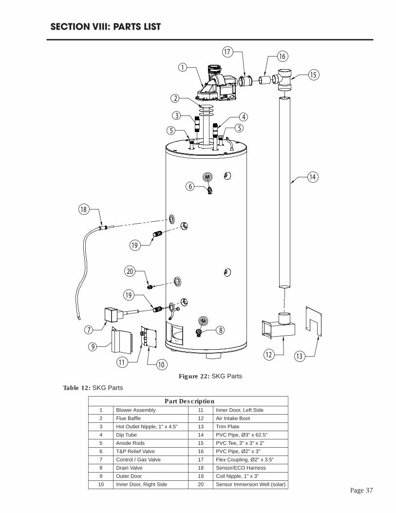
Page 37
SECTION VIII: PARTS LIST
1
2
3 4
5 5
6
7 8
9
11 1012 13
14
15
1617
18
19
19
20
Figure 22: SKG PartsTable 12: SKG Parts
Part Description1 Blower Assembly 11 Inner Door, Left Side2 Flue Baffle 12 Air Intake Boot3 Hot Outlet Nipple, 1" x 4.5" 13 Trim Plate4 Dip Tube 14 PVC Pipe, Ø3" x 62.5"5 Anode Rods 15 PVC Tee, 3" x 3" x 2"6 T&P Relief Valve 16 PVC Pipe, Ø2" x 3"7 Control / Gas Valve 17 Flex Coupling, Ø2" x 3.5"8 Drain Valve 18 Sensor/ECO Harness9 Outer Door 19 Coil Nipple, 1" x 3"10 Inner Door, Right Side 20 Sensor Immersion Well (solar)
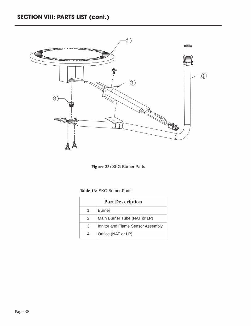
Page 38
SECTION VIII: PARTS LIST (cont.)
NO
1
23
4
Figure 23: SKG Burner Parts
Table 13: SKG Burner Parts
Part Description1 Burner2 Main Burner Tube (NAT or LP)3 Ignitor and Flame Sensor Assembly4 Orifice (NAT or LP)
SECTION IX: WARRANTY
LIMITED WARRANTY FOR SOLAR WATER HEATERBock Water Heaters, Inc.
110 S. Dickinson StreetMadison, WI 53703Phone: 608-257-2225
WHAT DOES THIS LIMITED WARRANTY COVER?This limited warranty applies only to the original consumer purchaser.
General Defects and Malfunctions: This warranty covers defections and malfunctions in your newwater heater for a period of one year from the original installation date. We will repair or replace,at our option, any defective or malfunctioning component of the water heater. This limitedwarranty will terminate if you sell or otherwise transfer the water heater, or the water heater isinstalled at a location different from its original installation location.
For water heaters installed in single family dwellings for residential use:
Tank and Heat Exchanger: We also warrant that the tank and heat exchanger will not leak due todefective materials or workmanship for six years from the date of original installation or from dateof manufacture in the event the Limited Warranty Registration Card was not completed andreturned to manufacturer. If the tank and heat exchanger is leaking and we have verified that theleak is due to a defect in materials and workmanship, we will replace the tank with a tank that isthe nearest Bock model available at the time of replacement. If a replacement tank is provided, itwill remain warranted under this section as if it were the original tank. For example, if we sendyou a replacement tank under this limited warranty two years after the original installation date,then the replacement tank will remain warranted for the remaining four years after the originalinstallation date.
For all water heaters NOT installed in single family dwellings and used exclusively forcommercial uses:
Tank and Heat Exchanger: We also warrant that the tank and heat exchanger will not leak due todefective materials or workmanship for five years from the date of original installation or fromdate of manufacture in the event the Limited Warranty Registration Card was not completed andreturned to manufacturer. If the tank and heat exchanger is leaking and we have verified that theleak is due to a defect in materials and workmanship, we will replace the tank with a tank that isthe nearest Bock model available at the time of replacement. If a replacement tank is provided, itwill remain warranted under this section as if it were the original tank. For example, if we sendyou a replacement tank under this limited warranty two years after the original installation date,then the replacement tank will remain warranted for the remaining three years after the originalinstallation date.
HOW DO YOU GET SERVICE UNDER THE LIMITED WARRANTY?In order for the warranty period to begin on the date of installation, you must return the warranty registrationcard attached below within 30 days of purchasing the water heater. You may also register your water heateronline at www.bockwaterheaters.com. You must have a copy of the original sales receipt at the time yourequest service. Failure to return the warranty registration card and provide a copy of the sales receipt
To get service under this limited warranty you should contact either the dealer or installer. If dealer or installer isunknown you can contact us via e-mail at [email protected] or call us Monday through Fridaybetween the hours of 8 o’clock a.m. to 5 o’clock p.m. Central Time at the following number: 1-608-257-2225.
You can also write us at the following address:
Bock Water Heaters, Inc.Warranty Support Group110 S. Dickinson StreetMadison, WI 53703
We will respond not later than ten days after we have received your request for service.
Page 39

Page 40
SECTION IX: WARRANTY (cont.)
WHAT DOES THIS LIMITED WARRANTY NOT COVER?This limited warranty does not cover water heaters that are or were:
• Incorrectly installed, especially where the installation violates state or local plumbing,housing or building codes.
• Operated at inappropriate settings, excessive pressures or temperatures. • Exposed to adverse local conditions and specifically sediment or lime precipitation in thetank or corrosive elements in the atmosphere or unacceptable water quality
• Installed outside the United States or Canada.• Accidentally damaged.
Also, we will not cover the following charges, costs and losses:
• Any freight or delivery charges.• Any removal or installation charges.• Charges to return the water heater or part to the manufacturer.• Water damage, loss or damage to property, inconvenience or loss of use.
WHAT WILL VOID THE LIMITED WARRANTY?If you do any of the following, you will void this limited warranty:
• Fail to retain an original copy of your sales receipt. • Fail to retain the actual rating plate from the water heater.• Alter or remove the serial number.• Transfer or sell the water heater.• Remove the water heater from its original location and install it somewhere else.• Fail to follow the care and maintenance instructions provided with the water heater. • Remove the anode rods.• Fail to inspect and replace the anode rods (you must retain and present your paid receiptsas proof of anode rod replacement).
HOW DOES STATE LAW RELATE TO THIS LIMITED WARRANTY?This is a limited warranty. WE MAKE NO OTHER EXPRESS WARRANTIES WITH RESPECT TOTHIS WATER HEATER. We will not assume, nor authorize any person to assume for us anyother liability in connection with the sale or operation of this water heater. ANY IMPLIEDWARRANTIES, INCLUDING MECHANTABILITY OR FITNESS FOR A PARTICULARAPPLICATION, IMPOSED ON THIS SALE UNDER THE LAWS OF THE STATE OF SALE ARELIMITED TO ONE YEAR. This warranty gives you specific legal rights, and you may also haveother rights which vary from state to state. Some states do not allow limitations on how longan implied warranty lasts, so the above limitation may not apply to you.
WE WILL NOT BE RESPONSIBLE FOR WATER DAMAGE, LOSS OF USE OF THE UNIT,INCONVENIENCE, LOSS OR DAMAGE TO PERSONAL PROPERTY, WHETHER DIRECT ORINDIRECT, AND WHETHER ARISING IN CONTACT OR TORT. Some states do not allow theexclusion of incidental or consequential damages, so the above exclusion may not apply toyou.
Bock Water Heaters, Inc. • 110 South Dickinson Street • Madison, WI 53703Telephone 608-257-2225 • Fax 608-257-5304
www.bockwaterheaters.com