
Solar Hydrogen Chronicles · 2016. 4. 8. · Solar Hydrogen Chroniclesincludes all of the articles...
273
Transcript of Solar Hydrogen Chronicles · 2016. 4. 8. · Solar Hydrogen Chroniclesincludes all of the articles...
Solar Hydrogen ChroniclesA Hands-On Guide toSolar Hydrogen Fuel:
ProductionPurification
StorageUtilization
A Collection of Articles about Hydrogen from Home Power Magazine
edited by Walt Pyle
Wheelock Mountain PublicationsWheelock VT USA
Content Copyright ©2003 H-Ion Solar Inc.E-book Design Copyright ©2003 Good Idea Creative Servicesi
Version 1-03. Copyright ©2003 H-lon Solar lnc. All rights reserved. E-bookdesign copyright ©2003 Good Idea Creative Services. Publisher, WheelockMountain Publications, 324 Minister Hill Road, Wheelock VT 05851, USA.
This booklet is sold for information use only. The buyer assumes completepersonal responsibility for the use or misuse of the information contained inthis booklet.
The articles in this e-book were originally published in Home Powermagazine in the period 1991-1998.
Although care is taken to present accurate information, the authors andpublisher will not retro-actively inform or re-imburse buyers if [or when]there are corrections or updates and revisions to this e-book.
Solar Hydrogen Chronicles
ii

Text links
Click on maroon colored text to go to a link within the e-book.
Click on blue colored text to go to an external link on the internet.The link will automatically open your browser. You must be connectedto the internet to view the externally linked pages.
Buttons
The TOC button will take you to the table of contents.
The left facing triangle will take you to the previous page.The right facing triangle will take you to the next page.
How to use this e-book
iii
iii How to Use This E-bookv Acknowledgmentsvi Forward
Introduction1 Hydrogen as a
Potential Fuel8 Hydrogen Basics
Production of Solar Hydrogen20 The Schatz PV Hydrogen
Project32 Hydrogen Fuel38 Water Electrolyzers44 Solar Hydrogen Production
by Electrolysis
Purification of Hydrogen69 Hydrogen Purification
Storage of Hydrogen95 Hydrogen Storage
Utilization of Hydrogen:Cooking118 Cookin’ on Hydrogen129 Barbecuing with
Hydrogen Gas
Utlization of Hydrogen:Space Heating143 Heatin’ with Hydrogen
Making Electricity with a Fuel Cell155 Understanding Fuel Cells169 Making Electricity with
Hydrogen
Transportation(Fuel Cells and Engines)187 Alternatives to Fossil Fueled
Engines/Generators223 Hydrogen Fuel Cells - the
Power Source of the '90s
Future Developments230 Direct Solar-Thermal
Hydrogen Production fromWater Using Nozzle/Skimmerand Glow Discharge
261 Linksii Disclaimer
Table of Contents
ivClick the chapter title or number
to go to that chapter.
Acknowledgments
v
The editor gratefully acknowledges the following authors,who shared their experience and knowledge about smallhome-sized applications of hydrogen technology, throughHome Power magazine articles.
David Booth
Reynaldo Cortez
John Dabritz
Mark Hayes
Jim Healy
Dr. Conrad Heins
Clifford W. Mossberg
Mark Newell
Richard Perez
Amanda Potter
L.E. Spicer
Alan Spivak
Dr. Robert Wills
Solar Hydrogen Chronicles includes all of the articles about hydrogenthat were published in Home Power magazine issues #1 to # 59 during the1990s. We wanted to get all of the "hands-on" Home Power articles onhydrogen together in one booklet to improve the access for those with aninterest in this topic.
Hydrogen is a non-carbon fuel, as defined below. And, hydrogen is anenergy carrier as well. It is referred to as an energy carrier because theenergy required to obtain hydrogen from water, or from a hydrocarbon, mustbe an input to the process. When combined with air or oxygen, hydrogencan be used as a fuel for many human needs, such as cooking, water heat-ing, space heating, electricity generation, and transportation. Hydrogencan also be used with air or oxygen in a torch for the welding, cutting, andheat-treating of various materials.
Fuel: A material that is bumed to release heat energy,for example, hydrogen, coal, oil, or uranium.
Solar hydrogen is a non-carbon fuel made from sustainable, renewableresources: sunlight and water. Our nearest star, the sun, produces radiantenergy that constantly reaches our planet. We experience this radiant ener-gy as heat and light. The arriving solar radiant energy can be converteddirectly into electricity by photo-voltaic [solar electric] cells, and indirectly by
Forward
vi
windmills, and hydroelectric turbines. The electricity produced by theserenewable resources can then be used to make hydrogen and oxygen fromwater by electrolysis. It is also possible to concentrate solar energy and useit in thermal processes that produce hydrogen and oxygen from water.
The emissions from a hydrogen flame contain no carbon oxides [nocarbon dioxide, CO2 , and no carbon monoxide, CO]. The emissions froma hydrogen air or hydrogen-oxygen flame do not contain hydrocarbons.
Hydrogen is a gas at ambient temperature and pressure. Hydrogen is thelightest gas known. It is much lighter than air, and is very buoyant in ouratmosphere. It has a Specific Gravity at 75° C and 1 atmosphere pressure of0.06952 [air = 1.00000].
At a very low temperature, 20.1° Kelvin [-252.9° C, or -423.2° F] andatmospheric pressure, hydrogen may be liquefied. Below O.l° K, hydrogenmay become slush or even solid.
The hydrogen atom [H] is the simplest atom, consisting of one proton andone electron with atomic weight 2.0l6. The electrons on hydrogen atomspossess spin and the hydrogen molecule [H2] is formed from two hydrogenatoms only when two hydrogen atoms with opposite spin are combined. Twoisomeric forms of hydrogen exist at equilibrium: ortho-hydrogen [parallelspin] and para-hydrogen [antiparallel spin]. At or above ambient tempera-ture, the equilibrium ratio is 75:25 ortho-para.
Forward
vii
Advantages of hydrogen as a fuel include:
• clean-burning nature• sustainability • versatility as a chemical feed-stock
Burning hydrogen with oxygen produces only water and heat as the com-bustion products. The water can be re-cycled by a solar hydrogen productionprocess to make more hydrogen and oxygen. This cycle can be repeatedessentially forever in human terms.
Disadvantages of hydrogen as a fuel include:
• lack of existing distribution infra-structure• difficulty of storage due to low energy density • wide flammable and explosive limits
The existing fuel distribution infra-structure consists of pipelines, tankers[ships, trains, trucks, airplanes] and service-stations that provide gaseousand liquid hydrocarbon fuels to homes, motor vehicles and industry. At thistime there is only a very limited bulk hydrogen distribution infra-structure. Afew short industrial hydrogen pipelines can be found in petro-chemical corri-dors. Most of the largest hydrogen production plants use the gas at the siteof manufacture [for example, petroleum refining, fertilizer production]. Small
Forward
viii
merchant supplies are often handled as compressed gaseous hydrogenusing heavy high-pressure steel cylinders, with a high associated unit cost.Hydrogen supplies for intermediate sized sites, such as rocket propulsion ormetallurgical processing plants, are usually handled as liquid hydrogen, anddelivered in tankers.
The hydrocarbon fuels provide excellent energy-storage-density. Hydrogendoes not enjoy a high energy storage density, and other ways must be foundto overcome this limitation. Section 4 on Hydrogen Storage gives the details
Flammability limits and detonation limits are wider with hydrogen thanwith hydrocarbon fuels. Whereas hydrocarbons can be stored safely over awide range of "rich" air-fuel ratios that are not flammable, the strategy forhydrogen storage is to store only pure gas [>99+% hydrogen].
At this juncture, most of the hydrogen used worldwide is produced by aprocess called "steam-reforming of hydrocarbons." Production of hydrogenat the present time, using the steam-reforming method, is not consideredsustainable. This is because the hydrocarbons now used [natural gas, oil,coal, etc.] come from finite fossil resources that are being rapidly depleted.In the future, steam-reforming of bio-mass hydrocarbons may be used toproduce hydrogen and hydrocarbons.
Forward
ix
In the near future, fuel cells, based on electro-chemical combustion ofhydrogen with air, can be expected to replace existing stationary and mobilepower plants. Those power plants now based on internal combustionengines and gas turbines will have poorer emissions and fuel economy per-formance than fuel cells. Fuel cells are now targeted for the transportationand distributed power generation sectors.
As we go to press on this First Edition of Solar Hydrogen Chronicles wehave recently witnessed tremendous political and environmental concernover Global Warming, that has been brought to focus by the KyotoConference. We believe hydrogen will play an important role in reducing ourman-made atmospheric contaminants and reaching the emissions reductiongoals that have been set.
Walt Pyle
Editor
March 2, 1998
Forward from the first edition
Forward
x
by Conrad HeinsOriginally published in Home Power #21 • February / March 1991©1991 Conrad Heins
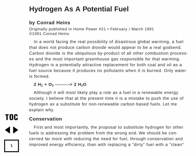
In a world facing the real possibility of disastrous global warming, a fuelthat does not produce carbon dioxide would appear to be a real godsend.Carbon dioxide is the ubiquitous by-product of all other combustion process-es and the most important greenhouse gas responsible for that warming.Hydrogen is a potentially attractive replacement for both coal and oil as afuel source because it produces no pollutants when it is burned. Only wateris formed.
2 H2 + O2 ---------> 2 H2O
Although it will most likely play a role as a fuel in a renewable energysociety, I believe that at the present time it is a mistake to push the use ofhydrogen as a substitute for non-renewable carbon based fuels. Let meexplain why.
Conservation
First and most importantly, the proposal to substitute hydrogen for otherfuels is addressing the problem from the wrong end. We should be con-cerned far more with reducing the need for fuel, through conservation andimproved energy efficiency, than with replacing a "dir ty" fuel with a "clean"
Hydrogen As A Potential Fuel
1
one. In the United States we use about twice as much energy as theGermans or Scandinavians to accomplish the same tasks, whether they beheating homes or driving to work. We need to focus not on the supply-sidebut on the demand side of the energy equation.
Application
A second, related point is that by addressing the problem in terms ofsupply we tend to ignore how the energy is being used, We fail to ask thecritical question, "Is this particular kind of energy the best answer for thisparticular application?" Only when this question is posed are we able to tomake judicious choices, especially if we want to take into account the sec-ond law of thermodynamics efficiency considerations, which deal with ener-gy quality as well as energy quantity, or environmental impacts.
Reaction
Third, hydrogen is a far more reactive chemical than any of the materialsthat are currently used as fuels. I am not talking about flammability orexplosiveness, but rather hydrogen's ability to undergo chemical reactionswith other compounds. It is a good reducing agent; it adds to double bonds,causing embrittlement of plastics and elastomers; and, because it is such atiny molecule, hydrogen can even work its way between the atoms of metalssuch as steel, causing hardening and embrittlement.
Hydrogen As A Potential Fuel
2
Unrenewable
Fourth, hydrogen is not made from a renewable energy source. Vir tuallyall of it is produced from natural gas, methane, by an endergonic reformingprocess that uses steam.
CH4 + 2 H2O-------------> CO2 + 4 H2
It might be argued that because part of it comes from water we areobtaining the hydrogen, at least partly, from a renewable resource. However,the energy captured in the hydrogen will always be less than the energy inthe methane plus the energy required to drive the reaction. And carbon diox-ide is still produced; as much, in fact, as would be formed if the methanewere burned as a fuel in the first place! Why waste energy to produce anenergy storage material that is far more difficult to store and handle thanthe fuel it is made from, especially when the starting fuel is the cleanestburning of any of today's primary energy sources.
It must be emphasized that hydrogen is made from natural gas becausethis is the least expensive way to make it - considerably less expensive, forexample, than of using electrolysis of water using electricity at off-peakrates. It is unrealistic to assume that, at least for the near term, hydrogenwould be made in any quantity from anything but methane. We are left withthe likelihood that the "hydrogen economy", like today's "hydrocarbon econo-my", would be based on a non-renewable resource.
Hydrogen As A Potential Fuel
3
Solar Hydrogen
Of course, it is possible to break apart water and obtain hydrogen inother ways. The formation of hydrogen and oxygen from water using elec-tricity is the one that is most often touted. If the electricity is provided byPV panels, we are talking about using a renewable energy resource, sun-light, to provide hydrogen in a non-polluting way. Such a proposal, whenfirst heard, sounds attractive. However, a little further examination indi-cates that is not a good answer.
The biggest problem is the prodigious amount of electrical energy thatwould be required to replace even a portion of the hydrocarbon fuels wenow use. Wilson Clark, in his classic book, Energy For Survival, makes hispoint very clear.
"The amounts of hydrogen that would be required in a hydrogen econo-my are enormous. For instance, according to Dr. Gregory, to produceenough hydrogen to fully substitute for the natural gas produced in theUnited States at the present time [1974] - i.e., 70 trillion cubic feet ofhydrogen - would require more than 1 million megawatts of electric powerto produce. Total electric generating capacity in the United States is only360,000 megawatts. To meet the projected hydrogen requirements for natu-ral gas alone would call for a fourfold increase in generating capacity,
Hydrogen As A Potential Fuel
4
which would mean building 1,000 additional 1,000-megawatt power stations!This does not provide for increased electric power demand for other purpos-es, nor does it take into account the generation of hydrogen for transportfuel or as an additive in chemical and industrial processes."
By way of comparison, world production of photovoltaic generating capaci-ty was about 50 megawatts (peak sun) last year. Even if this capacity wereto be increased a 100-fold and all of it used to produce hydrogen, we wouldstill be making a fraction of 1% of what would be needed to replace the nat-ural gas consumed in the U.S. In addition...
Storage
Why use electricity, the most versatile form of energy available, to pro-duce a material that is not easily stored (the boiling point of hydrogen is -435°F, about 22°K above absolute zero) or handled and that will probably beburned to produce mechanical energy in a process that will be less than30% efficient... when the electricity might be used directly?
If energy storage is needed, why do it through such a difficult-to-storematerial for which large scale storage technologies do not even exist, whenelectricity can be stored in batteries, flywheels or pumped storage systemsfar more effectively?
Hydrogen As A Potential Fuel
5
Efficiency
If it is to be used for transportation, why select a process that will operateat no more than 30% efficiency (an internal combustion engine) when anelectric motor can be used that is at least 75% efficient? And why select afuel that is so difficult to deal with in a mobile situation? (Wilson Clark, oneof the early proponents of hydrogen fuel, includes a good discussion of thehydrogen powered automobile in Energy For Survival. He points out that aDewar flask type container for liquid hydrogen that would that would hold theenergy equivalent of 15 gallons of gasoline would have to be about 37 gal-lons in size and would cost (1974 prices) about $1,800. The use of metals,such as magnesium, to store hydrogen as a metal hydride would require aneven larger volume).
Why Photovoltaics
Finally, why photovoltaics? As pointed out earlier, photovoltaics is not agood choice for generating vast amounts of electricity. It is much more suit-able for smaller scale applications where grid power is not available.Although it will probably be used to generate utility power as well, utilitieshave never considered using it in any other capacity than for peaking power.In addition, these systems presently produce electricity at a cost of from$.25 to $.75 per kilowatt hour (20 year life cycle cost). Even were the cost to
Hydrogen As A Potential Fuel
6
be cut in half, which is what we expect to happen during the next decade,we are talking about a much more expensive kind of electricity than couldbe produced by other renewable sources, such as the LUZ concentratingsolar thermal facility that is presently supplying peaking power to the LosAngeles basin at about $.08 per kilowatt hour.
If these questions are answered primarily by, "because photovoltaics isrenewable and non-polluting, and the burning of hydrogen produces no pol-lutants", I suggest that a much more thorough analysis of the situationneeds to be carried out.
Access
Dr. Conrad Heins teaches a course in renewable energy, including photovoltaics, at Jordan College, 155 Seven Mile Rd, Comstock Park, MI 49321
Hydrogen As A Potential Fuel
7
by Amanda Potter and Mark NewellOriginally published in Home Power #32 • December 1992 / January 1993©1992 Mark Newell and Amanda Potter
Home Power is gearing up to use hydrogen fuel for cooking. We’ve beenhoping to eliminate or at least reduce our propane use for a long time nowand have been encouraged by the interest and enthusiasm in hydrogen thatwe’ve seen in our readers.
Hydrogen is not a source of energy; rather, it is a non-toxic means of stor-ing and transporting energy. Any energy source can be stored in the form ofhydrogen. Solar, wind and hydro power can be used to break down themolecular bonds which bind hydrogen in hydrocarbons and water. Hydrogen,unlike electricity, is efficiently transported over long distances (throughpipelines, for example). It enables energy produced in areas where renew-able energy resources are abundant to be safely transported to areas withhigh energy use. Part of hydrogen’s vir tue as an energy storage medium isthe fact that energy stored in the form of hydrogen can be converted intodifferent forms of usable energy without producing pollutants. Heat or elec-tricity can be produced, with water as the primary by-product.
Catalytic Combustion
Hydrogen can be recombined with oxygen to produce heat in the normalcombustion process or it can be recombined in a fuel cell to produce elec-
Hydrogen Basics
8
tricity. In both cases the primary by-product is water. Burning hydrogen pro-duces some nitrous oxides because of the high burning temperature.However, using a catalyst (such platinum or nickel) lowers the temperatureand decreases the surface area of the reaction, which increases efficiencyand reduces the nitrous oxides to a negligible amount. Pure catalytic com-bustion uses a catalyst to cause the hydrogen-oxygen recombination tooccur without the input energy of a flame. There is a 100% efficient conver-sion of hydrogen to heat when temperatures are kept below 100° Celsius or212° Fahrenheit.
Converting a propane stove to run on hydrogen is a fairly simple process.Low tech, inexpensive catalysts such as stainless steel wool (3%-22% nick-el) work well and are easy to use. However, stainless steel wool is not aseffective in eliminating nitrous oxides as more expensive catalysts. For moreinformation on these operations see Fuel From Water by Michael Peavey.Also look in your local library under hydrogen.
The Electrolyzer
An electrolyzer is a device that uses electric current to electrolyse or splitwater (H2O) into hydrogen and oxygen. (See Electrolyzer Physics, p.17)Electrolysis is currently the cheapest, simplest, and most efficient method ofhome scale hydrogen generation. Well-made and relatively inexpensive elec-
Hydrogen Basics
9
trolyzer cells are available from Hydrogen Wind in Iowa. Each electrolyzercell requires 2 Volts; the current determines how much hydrogen they pro-duce. (See Hydrogen Fuel, p.32 and Water Electrolyzers, p.38.)
How Much Hydrogen Would We Use?
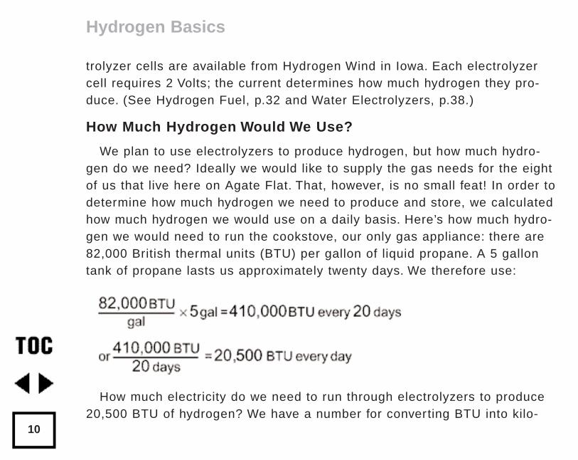
We plan to use electrolyzers to produce hydrogen, but how much hydro-gen do we need? Ideally we would like to supply the gas needs for the eightof us that live here on Agate Flat. That, however, is no small feat! In order todetermine how much hydrogen we need to produce and store, we calculatedhow much hydrogen we would use on a daily basis. Here’s how much hydro-gen we would need to run the cookstove, our only gas appliance: there are82,000 British thermal units (BTU) per gallon of liquid propane. A 5 gallontank of propane lasts us approximately twenty days. We therefore use:
How much electricity do we need to run through electrolyzers to produce20,500 BTU of hydrogen? We have a number for converting BTU into kilo-
Hydrogen Basics
10
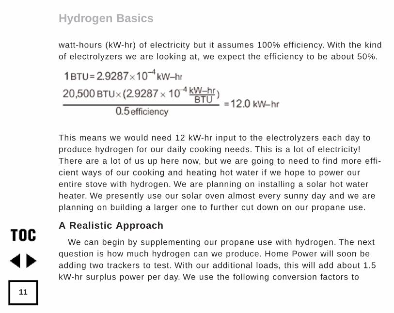
watt-hours (kW-hr) of electricity but it assumes 100% efficiency. With the kindof electrolyzers we are looking at, we expect the efficiency to be about 50%.
This means we would need 12 kW-hr input to the electrolyzers each day toproduce hydrogen for our daily cooking needs. This is a lot of electricity!There are a lot of us up here now, but we are going to need to find more effi-cient ways of our cooking and heating hot water if we hope to power ourentire stove with hydrogen. We are planning on installing a solar hot waterheater. We presently use our solar oven almost every sunny day and we areplanning on building a larger one to further cut down on our propane use.
A Realistic Approach
We can begin by supplementing our propane use with hydrogen. The nextquestion is how much hydrogen can we produce. Home Power will soon beadding two trackers to test. With our additional loads, this will add about 1.5kW-hr surplus power per day. We use the following conversion factors to
Hydrogen Basics
11
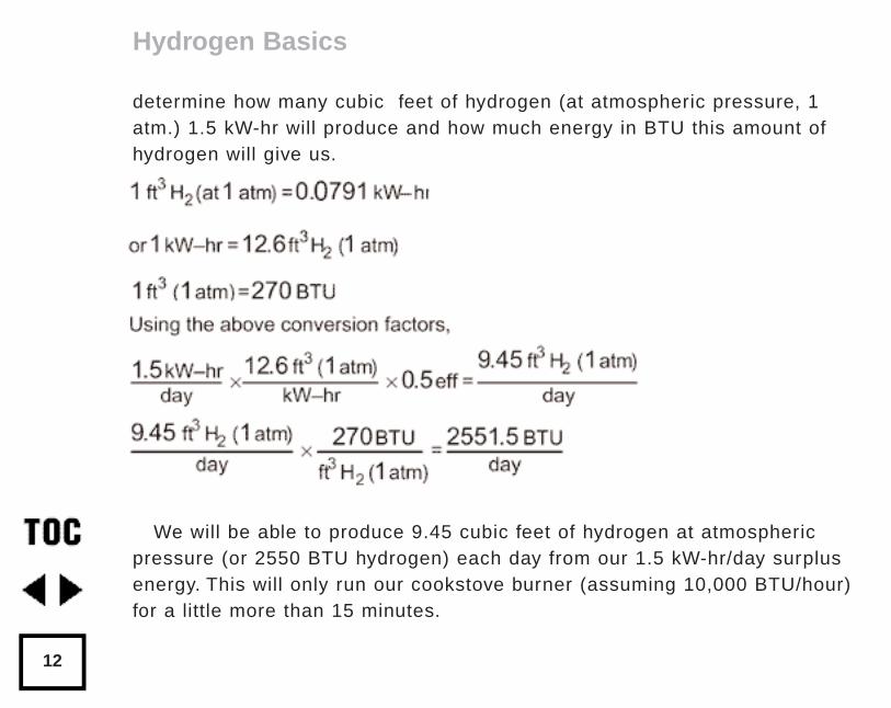
determine how many cubic feet of hydrogen (at atmospheric pressure, 1atm.) 1.5 kW-hr will produce and how much energy in BTU this amount ofhydrogen will give us.
We will be able to produce 9.45 cubic feet of hydrogen at atmosphericpressure (or 2550 BTU hydrogen) each day from our 1.5 kW-hr/day surplusenergy. This will only run our cookstove burner (assuming 10,000 BTU/hour)for a little more than 15 minutes.
Hydrogen Basics
12
Storage
Now that we have the hydrogen, how do we save it until we need it?Hydrogen storage can be complicated and costly. Hydrogen can be storedas a liquid, in a metal hydride, or as a pressurized gas. Liquid hydrogen at -253°C requires costly and complex storage containers and the energyrequired to liquify hydrogen is 20-40% of the energy being stored. Certainmetals like magnesium, titanium, and iron absorb hydrogen when cooledand release it when heated. In these metals, hydrogen remains a gas but isconfined in the spaces between molecules in the metal. When the metal is“charged” with hydrogen, it is called a metal hydride. Metal hydrides are thesafest way to store hydrogen, especially in transportation applications, butare also more costly and complex than pressurized gas. Hydrogen can bestored as a gas at high or low pressures. High pressure systems allowsmaller tanks but require expensive compressors. We are considering rela-tively low pressure storage options because we would like to keep our stor-age system as simple as possible.
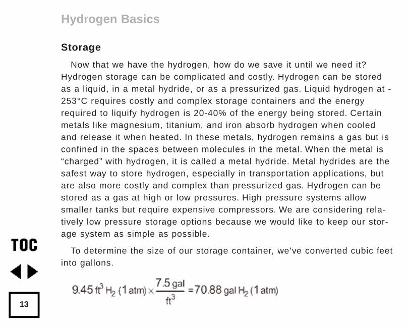
To determine the size of our storage container, we’ve converted cubic feetinto gallons.
Hydrogen Basics
13
The Ideal Gas Law
When we talk about storage, we also need to talk about the pressure. Theabove equation assumes we are storing the hydrogen at just above atmos-pheric pressure.
Hydrogen, stored as a gas, follows the ideal gas law, PiVi =PfVf. The lawstates that the initial pressure times the initial volume of a gas is equal tothe final pressure times the final volume of the gas.
Pressure in the ideal gas law must include atmospheric pressure. Whenwe inflate a tire to 35 pounds per square inch (psi), we are actually inflatingit to 35 psi above atmospheric pressure. Atmospheric pressure is the pres-sure per square inch exerted on us by the atmosphere above us. It variesaccording to elevation and temperature but is about 14.5 psi. Anything lessthan that is a vacuum; anything more is pressurized. So, the tire we inflatedwould actually be at 35 + 14.5 psi or 49.5 psi. The tires walls only “feel” 35psi because atmospheric pressure presses on it.
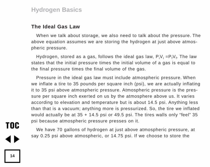
We have 70 gallons of hydrogen at just above atmospheric pressure, atsay 0.25 psi above atmospheric, or 14.75 psi. If we choose to store the
Hydrogen Basics
14
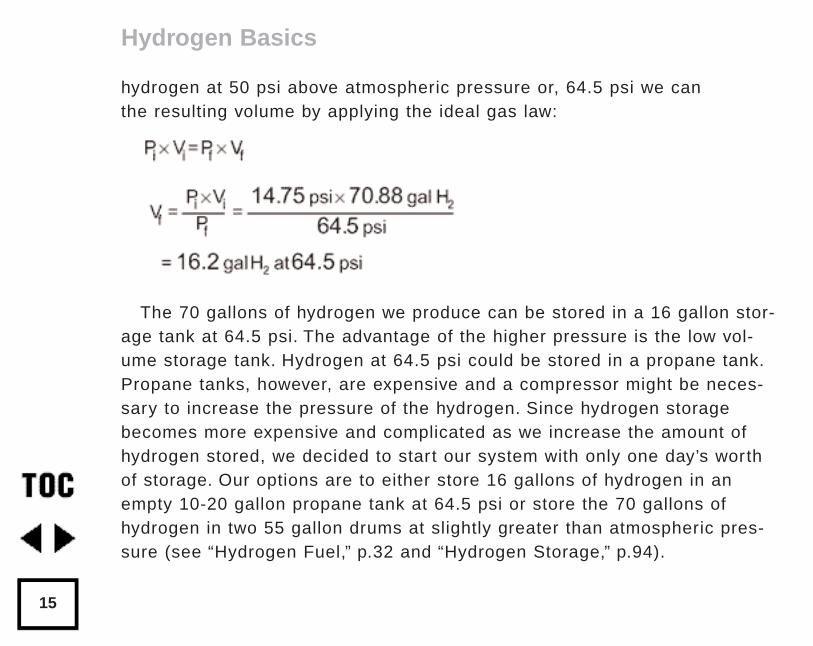
hydrogen at 50 psi above atmospheric pressure or, 64.5 psi we can the resulting volume by applying the ideal gas law:
The 70 gallons of hydrogen we produce can be stored in a 16 gallon stor-age tank at 64.5 psi. The advantage of the higher pressure is the low vol-ume storage tank. Hydrogen at 64.5 psi could be stored in a propane tank.Propane tanks, however, are expensive and a compressor might be neces-sary to increase the pressure of the hydrogen. Since hydrogen storagebecomes more expensive and complicated as we increase the amount ofhydrogen stored, we decided to start our system with only one day’s worthof storage. Our options are to either store 16 gallons of hydrogen in anempty 10-20 gallon propane tank at 64.5 psi or store the 70 gallons ofhydrogen in two 55 gallon drums at slightly greater than atmospheric pres-sure (see “Hydrogen Fuel,” p.32 and “Hydrogen Storage,” p.94).
Hydrogen Basics
15
Hydrogen For Home Power Users
Hydrogen offers many possibilities for home power users. Indefinite, longterm storage becomes possible with hydrogen. Many home power systemsproduce more power than can be used during only one season. PV’s pro-duce surplus power in the summer; micro-hydro systems produce surpluspower in the winter. Hydrogen allows for the storage of the surplus energyproduced during one season to be used in another. Hydrogen can be com-busted to produce heat for cooking or space heating with no pollutants. Itgives home power producers the option of eliminating the last of their fossilfuels. Hydrogen can also be added directly into an existing propane supply.Hydrogen mixes with propane and can be used in a propane appliancesyear-round, without any modifications, to conserve propane (see “HydrogenFuel,” p.32).
In the foreseeable future, we may see fuel cells become a cost-effectivemethod of producing electricity with stored hydrogen. Hydrogen could thenbe used as an alternative to batteries, which require proper maintenanceand employ toxic heavy metals which eventually need to be disposed ofor recycled.
This exercise has given us a good idea of what it will take to replace allof our propane use with hydrogen. It’s brought home the importance of con-
Hydrogen Basics
16
servation; our solar oven and solar hot water heater will determine if ourtransition will be possible. There is little information on “home scale, homebudget” hydrogen systems. We welcome any advice or experience.
Electrolyzer Physics
An electrolyzer is a device that uses direct current electricity to break thebonds holding together water, H2O, into its components hydrogen, H, andoxygen, O.
An electrolyzer has three main components: an electrolyte, two electrodesand a separator. The electrolyte solution consists of distilled water and asalt, acid, or base, and is held in a chamber. The electrodes are pieces ofmetal which sit in the electrolyte and pass current through the electrolyte.The separator is a barrier that physically separates the electrodes from eachother yet allows current to flow between them.
The Process
The following reactions occur when the electrolyte is a 30% solution ofpotassium hydroxide, KOH. If another electrolyte is used the results will bethe same although the reactions will be different.
When DC electricity is connected to the two electrodes, current passesthrough the solution (H2O and KOH), decomposing the chemical bonds of
Hydrogen Basics
17
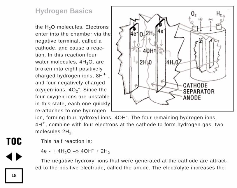
the H2O molecules. Electronsenter into the chamber via thenegative terminal, called acathode, and cause a reac-tion. In this reaction fourwater molecules, 4H2O, arebroken into eight positivelycharged hydrogen ions, 8H+ ,and four negatively chargedoxygen ions, 4O2
-. Since thefour oxygen ions are unstablein this state, each one quicklyre-attaches to one hydrogenion, forming four hydroxyl ions, 4OH-. The four remaining hydrogen ions,4H+, combine with four electrons at the cathode to form hydrogen gas, twomolecules 2H2.
This half reaction is:
4e - + 4H2O –» 4OH- + 2H2
The negative hydroxyl ions that were generated at the cathode are attract-ed to the positive electrode, called the anode. The electrolyte increases the
Hydrogen Basics
18
conductivity of the water, allowing the hydroxyl ions to be pulled to theanode. At the anode another reaction takes place in which the four hydroxylions give up four electrons and form oxygen gas, O2 , and two water mole-cules, 2H2O. These electrons leave the chamber via the anode to completethe circuit. The oxygen and hydrogen gas, kept separate by a barrier, bubbleup through the electrolyte into separate pipes and off to their points of useor storage. This reaction looks like:
4OH –» O2 + 2H2O + 4e-
The overall result of the two reactions looks like this:
2H2O –» O2 + 2H2
Access:
Mark Newell and Amanda Potter, c/o Home Power, POB 520, Ashland, OR 97520 • 916-475-3179
Fuel From Wate by Michael A. Peavey, (ISBN 0-945516) Merit Products,Inc., Box 694, Louisville, KT 40201. Also available from AlternativeEnergy Engineering.
Hydrogen Basics
19
by Richard PerezOriginally published in Home Power #22 • April / May 1991
The Schatz PV Hydrogen Project
20
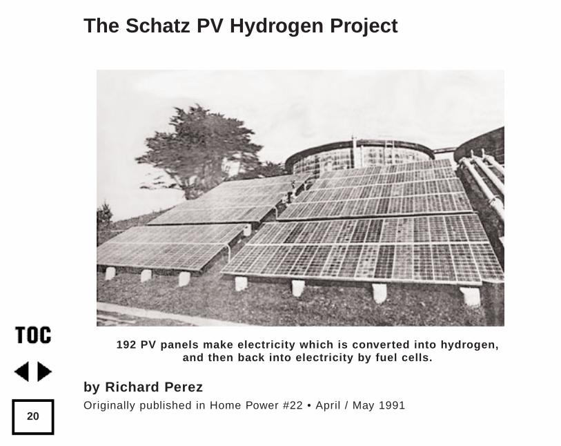
192 PV panels make electricity which is converted into hydrogen,and then back into electricity by fuel cells.
Many of us dream of more efficient ways to store the power we make from renewableenergy sources. Here's a system that uses sunlight to make hydrogen and oxygengas. These stored gases are converted directly into electricity by a fuel cell. Soundfuturistic and impossible? Well, it's happening at Humboldt State University in Arcata,California.
An opportunity we couldn't refuse
I recently attended a conference on energy conservation at Humboldt StateUniversity. One of the conference's organizers, Michael Welch of the RedwoodAlliance, suggested we visit an experimental PV/Hydrogen project at theschool. It was an opportunity that we couldn't pass up. So, Bob-O Schultze andI saddled up and headed for the Humboldt Hydrogen.
The People
Renewable power systems are born because someone decides to build them.It is the interest and intelligence of the system's inventors/designers/users thatmakes it a reality. The hardware is secondary to the human desire to do it. Wehave technology coming out of our ears and we still fight wars over the oil thatis slowly killing us. Renewable energy is worthless if we don't use it.ThePV/Hydrogen project is the work of Dr. Peter Lehman and the crew of theEnvironmental Resources Engineering Dept. at Humboldt State. Bob-O and Iwere prepared for an ivory-tower tour focusing on the age encrusted ideas
The Schatz PV Hydrogen Project
21
chiseled indelibly in stone. What we found was entirely alive, open, andgrowing. These folks' project is as real as a physics book, but their feet aredangling over the edge of energy reality, just like those of every home powerproducer. We instantly found ourselves at home with folks that shared thesame dreams, concepts, and fears that we have. It was enough to make mewant to go back to college.
The Concept
Sunlight makes hydrogen that makes electricity.
The concept of the Schatz Solar Hydrogen Project is not very differentfrom home power systems, with one exception. The power here is stored ashydrogen and oxygen gases rather than in a battery.
An 8,000 Watt photovoltaic array directly converts sunlight into electricity.The power of the array feeds an electrolyzer cell. The electrolyzer convertsthe array's power into hydrogen gas and oxygen gas by electrolysis of water.These gases are stored in tanks for use at night or on overcast days. Thehydrogen and oxygen gases are fed into a fuel cell for direct conversion intoDC electric power. The DC electricity, either from the array direct or from thefuel cell, is converted into 120 vac by an inverter. The load supplied by thissystem is the aeration compressor bubbling air into the Marine Lab's fish
The Schatz PV Hydrogen Project
22
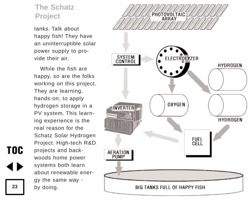
tanks. Talk abouthappy fish! They havean uninterruptible solarpower supply to pro-vide their air.
While the fish arehappy, so are the folksworking on this project.They are learning,hands-on, to applyhydrogen storage in aPV system. This learn-ing experience is thereal reason for theSchatz Solar HydrogenProject. High-tech R&Dprojects and back-woods home powersystems both learnabout renewable ener-gy the same way - by doing.
The SchatzProject
23
The PV Array
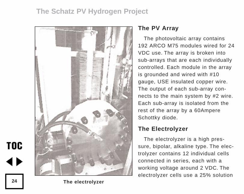
The photovoltaic array contains192 ARCO M75 modules wired for 24VDC use. The array is broken intosub-arrays that are each individuallycontrolled. Each module in the arrayis grounded and wired with #10gauge, USE insulated copper wire.The output of each sub-array con-nects to the main system by #2 wire.Each sub-array is isolated from therest of the array by a 60AmpereSchottky diode.
The Electrolyzer
The electrolyzer is a high pres-sure, bipolar, alkaline type. The elec-trolyzer contains 12 individual cellsconnected in series, each with aworking voltage around 2 VDC. Theelectrolyzer cells use a 25% solution
The Schatz PV Hydrogen Project
24 The electrolyzer
of potassium hydroxide (KOH) in water. The plates of the cells are madefrom stainless steel. This electrolyzer is made by Teledyne Energy for manu-facturing processes that require pure hydrogen. It produces about 20 litersof hydrogen gas per minute and is between 75% and 80% efficient.
The gas output of the electrolyzer is metered by a mass flow calorimeter,a visual flow meter, and mechanical pressure gauges.
The oxygen gas is far from pure as it leaves the electrolyzer's cells. Theoxygen output of the electrolyzer still contains small amounts of hydrogengas and vast amounts of water vapor. The oxygen gas is first run into atube-in-tube condenser that turns the water vapor into a liquid that isremoved. The dryer oxygen gas then passes into a catalytic scrubber thatcombines the minute amounts of remaining hydrogen gas with the oxygengas and produces water. The water is drained off and then the wholeprocess of condenser/catalytic scrubber is repeated. The net result is verypure, very dry oxygen gas that is stored in the tank.
The electrolyzer requires only minimal maintenance - the replenishment ofits electrolyte about every six months of continuous operation.
The Storage System
Both the hydrogen and oxygen gases produced in the electrolyzer arestored for later use in the fuel cell. These gases are stored in three 500 25
The Schatz PV Hydrogen Project
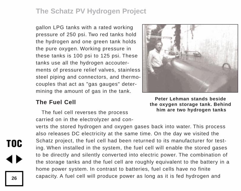
gallon LPG tanks with a rated workingpressure of 250 psi. Two red tanks holdthe hydrogen and one green tank holdsthe pure oxygen. Working pressure inthese tanks is 100 psi to 125 psi. Thesetanks use all the hydrogen accouter-ments of pressure relief valves, stainlesssteel piping and connectors, and thermo-couples that act as "gas gauges" deter-mining the amount of gas in the tank.
The Fuel Cell
The fuel cell reverses the process carried on in the electrolyzer and con-verts the stored hydrogen and oxygen gases back into water. This processalso releases DC electricity at the same time. On the day we visited theSchatz project, the fuel cell had been returned to its manufacturer for test-ing. When installed in the system, the fuel cell will enable the stored gasesto be directly and silently converted into electric power. The combination ofthe storage tanks and the fuel cell are roughly equivalent to the battery in ahome power system. In contrast to batteries, fuel cells have no finitecapacity. A fuel cell will produce power as long as it is fed hydrogen and
The Schatz PV Hydrogen Project
26
Peter Lehman stands besidethe oxygen storage tank. Behind
him are two hydrogen tanks
oxygen. The storage capacity of the system is limited by the size of thehydrogen and oxygen tanks, not by the size of the fuel cell.
The outputs of the fuel cell are DC electricity and water. That's it. Theentire system produces no polluting byproducts - no carbon dioxide, no sul-fur dioxide, and no radioactive waste. The entire process is totally symmetri-cal. Water molecules are transformed into their elemental components ofhydrogen and oxygen. The hydrogen and oxygen atoms are recombined intowater molecules. The system's creators bank the solar energy in tanks andretrieve it when needed.
This particular fuel cell is made by Energenics of Ringwood, New Jersey.This fuel cell is a proton exchange membrane type that is capable of makingeffective use of the pure oxygen made by the electrolyzer. This fuel cell isan "instant-on" version that runs at lower temperatures (70°C.) than otherversions (like the phosphoric acid version at 150°C. & the molten carbonateversion at 800°C.). This Energenics version puts out 750 Watts continuously.The Energenics Company is working hand-in-hand with the Schatz project inresearch and development of retrieving energy stored in hydrogen.
The Inverter
We expected to find a high-dollar, super inverter in such an advanced sys-tem. Instead, we found the same garden variety Trace Inverter used in thou-
The Schatz PV Hydrogen Project
27
sands of home power households. A Trace 2032 Inverter hummed happily onthe wall. It doesn't care if its DC power comes directly from the PV arrayduring the day, or from the fuel cell at night. The Trace is very democratic,and very reliable; it keeps the fish alive & happy.
System Control and Instrumentation
The instrumentation and control on the Schatz project are extensive. Afterall, the major product here is information. The system is monitored by com-puters at every stage of the process. Seven optoisolated, analog to digitalconverter boards talk to the system's twoMacintosh computers. System control isaccomplished by shorting out individualsub-arrays. This is accomplished by com-puters controlling 30 Ampere relays. Abank of NIFE Sunica nickel-cadmium cellsis floated on the array to act as a "fly-wheel" to prevent constant relay switchingduring power surges.
The System's Safety
A clear Lucite cage contains all hydro-gen handling components. This cage
The Schatz PV Hydrogen Project
28
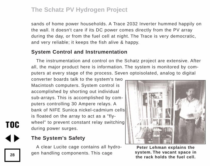
Peter Lehman explains the system. The vacant space in the rack holds the fuel cell.
vents outside and operates at less air pressure than the room in which itlives. Any hydrogen leaks are instantly detected by ultra sensitive hydrogensniffers and the system is automatically shutdown. All piping within the sys-tem is stainless steel. The electrical components are protected with everyknown fuse, breaker, and disconnect. The entire system will not only meet theNEC, but it will make the most paranoid electrical inspector feel safe. ThisPV/hydrogen installation is safer than your kitchen stove or hot water heater.
The Reasons Why
The first reason is to learn how to store PV produced power as hydrogen.The second reason is to learn how to retrieve this stored energy through afuel cell. The Schatz project is research and development in the use of solarhydrogen. The project is funded by Mr. L.W. Schatz, president of GeneralPlastics Manufacturing Company of Tacoma, WA. My compliments to Mr.Schatz for looking far beyond the next quarter's profits and into an energyfuture we can all share.
Hydrogen Home Power?
Well, not yet. But, Peter Lehman and his compatriots are working on it.This system is far too costly and complex for basic home power right now.That's what Peter and the crew are working on. In the future, when we'reusing hydrogen for power storage, then it will be because folks like theHumboldt crew did their work right now.
The Schatz PV Hydrogen Project
29
Hopelessly Hi-Tech?
Not on your life. After a morning of sunshine hydrogen flowing throughpolished stainless steel, we visited another project at Humboldt State - theCampus Center for Appropriate Technology (CCAT). CCAT makes renewableenergy real right now. The CCAT building uses PVs and wind for power (bat-tery storage here), solar hot water, efficient appliances, a solar greenhouseproviding space heat as well as fresh veggies, and even composting toilets.The CCAT building houses students in the Environmental ResourcesEngineering program and gives them the same hands-on experiences livedby home power producers. These students get to live on renewable poweron a daily basis, learn about the systems involved, and create their ownvariations. They are an intense crew. I could see their commitment from thewell-thumbed copies of Home Power on their bookshelves. The students atCCAT were not only learning new things, but are willing to share what theyhave learned. They have promised to write about their experiences in thenext issue of Home Power.
Conclusion
Hydrogen storage is coming. The students and faculty at Humboldt Stateare joyously pushing the edge of the energy envelope. When I was in schoolthe only things under discussion were building better bombs and nukes too
The Schatz PV Hydrogen Project
30

cheap to meter. To find an established center of learning with a heart and aneye to our future gives me great hope. As I said, "It makes me want to goback to school."
Access
Dr. Peter Lehman, Director of the Schatz Solar Hydrogen Project,Environmental Resources Engineering Dept.,Humboldt StateUniversity, Arcata, CA 95521 • 707-677-0306 or 707-826-4231.
Richard Perez, c/o Home Power, POB 130, Hornbrook, CA 96044916-475-3179.
The Schatz PV Hydrogen Project
31
by L.E. SpicerOriginally published in Home Power #22 • April / May 1991©1991 L.E. Spicer
Hydrogen is an abundant fuel and it is simple to make. Above the initialcost of the generating equipment, the hydrogen produced can be free. Theonly substances used up in making hydrogen are water and electricity. Myelectricity comes from a wind generator and the water I use is rainwater. Byusing solar cells, the entire process can be done without one moving part.
Hydrogen's Traits
I consider hydrogen to be a much safer fuel than gasoline or propane.Hydrogen has a built-in safety factor because it is the lightest element. Uponrelease it disperses very rapidly, rising straight up, and is lost as soon as itis released. Hydrogen disperses so quickly that a gas welding torch will notlight unless the spark is next to the gas outlet. An ordinary acetylene weldingtorch can be used with hydrogen. The hydrogen flame is clear and to adjustthe flame you will need to look at the glow coming from the metal. In brightdaylight the hydrogen oxygen flame cannot be seen.
Hydrogen Fuel
32
Adjustments
A few simple adjustments can be made to your propane cooking stove tomake it operate on hydrogen. Fill any large venturi cavity with steel wool toprevent a popping noise. Nex, adjust the jet size, regulate the pressure, andclose off all air at the jet.
Gasoline engines can also be adjusted to run on hydrogen. I have adapt-ed a propane/air mixer to a gasoline carburetor with success using hydrogenas a fuel. A standby gas generator set adapted to hydrogen would be a goodarrangement.
A better use of hydrogen that I would like to see, rather than wasting it ona low efficiency gas motor, would be the use of a hydrogen-oxygen fuel cell.A fuel cell can be used for electricity or to run a vehicle with good efficiency.
Storage
I store my hydrogen in a 500 gallon propane tank. Propane and hydrogenare compatible in the same tank. In fact, propane can be conserved by bub-bling hydrogen into it. Another advantage to putting hydrogen in propanetanks is to add smell to it, and to avoid mixing your hydrogen with oxygenfrom the air. Propane tanks also have a pressure release valve set at 250PSI. I have had no problems with storing hydrogen below this pressure.Hydrogen and oxygen must be stored in separate tanks. The only time to
Hydrogen Fuel
33
combine oxygen or air to hydrogen is at the burn site. Hydrogen and oxygenmixed and ignited is explosive, same as any hydrocarbon fuel.
Electrolysis
In my electrolyzer cell, the hydrogen evolves off the negative potential;the positive potential releases the oxygen. It is important to maintain thesame polarity on an electrolyzer cell. If the polarity is switched, your gaseswill be mixed. I use nickel on the positive side along with potassium hydrox-ide as an electrolyte. Nickel electrodes in potassium hydroxide do not elec-troplate away. Pure water is a non-conductor of electricity. Therefore, apotassium hydroxide electrolyte is necessary. The potassium hydroxide isnot used up is the process of electrolysis. I purchase my potassium hydrox-ide from a chemical warehouse.
I use the hydrogen gas for combustion. I use the oxygen gas produced forwelding, especially for cutting which uses lots of oxygen. I haven't boughtoxygen for my cutting torch since I installed the hydrogen setup.
Homemade Electrolytes
If you want to make your own electrolyte, it can be made from woodashes. First, soak your wood ashes for a period of time, depending on howconcentrated you want your solution. Remove the clear solution off the topof the wood ashes, then evaporate down to the specific gravity you want
Hydrogen Fuel
34
your electrolyte to be at. A weak solution works fine, and is not as causticas a stronger solution.
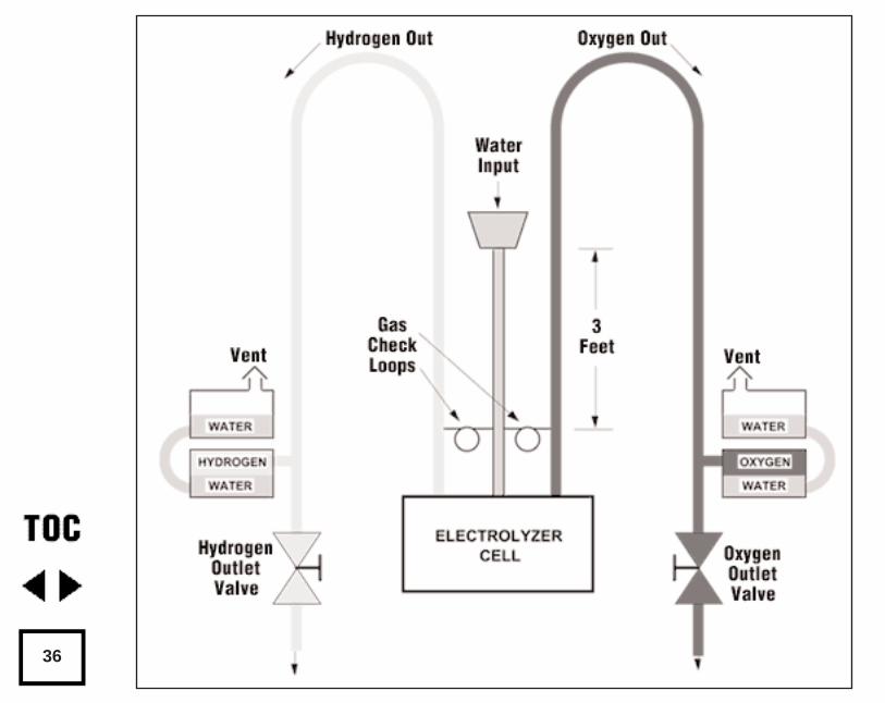
Gas Pressure
Hydrogen and oxygen gas will evolve from the electrolyzer under pres-sure. This can be taken advantage of by using a hydrostatic column toobtain pressure. See the illustration, next page. This one cell electrolyzeralong with this simple three foot hydrostatic control will give pressurizedstorage of both hydrogen and oxygen with no moving parts. The pressure isobtained from the weight of the three foot water column. This is sufficientpressure to displace the water from the bottom 55 gallon barrel to the topbarrel. The water in the top barrel in turn puts pressure on the gas. A seriesof 55 gal. drums can be lined up in this fashion to store larger quantities ofgas. There is no need for gauges as the liquid level can readily be seenthrough the clear tubing. There are no pop-off valves to be concerned with.After adding the electrolyte to the system, only water and electricity areneeded for continued operation. A fail-safe feature of this control is that thehydrogen and oxygen go into storage or are vented into the air.
Controls & Power Sources
I also build a 50 PSI control that operates three electrolysis cells in serieswhich operate at 12 Volts DC and 40 Amperes.
Hydrogen Fuel
35
36
My larger control is a 100 PSI control which can handle six or more elec-trolyzer cells in series. I presently have a six cell unit with a 100 PSI controlin my shop. It is powered by a Jacobs wind generator. Each cell requires 4Volts DC. These are wired in series and operate at 24 Volts DC and will loadto 40 amps with each cell delivering 1/ 2 cubic foot of hydrogen per hour on awindy day.
A good power source to drive a one cell electrolyzer is a high amperagesix Volt wind generator. Another good source would be a permanent magnetmotor driven by water.
Access
L.E. Spicer, Hydrogen Wind, Inc. RR#2 Box 262, Lineville, Iowa 50147 •641-876-5665.
Hydrogen Fuel
37
by L. E. SpicerOriginally published in Home Power #26 • December 1991 / January 1992©1991 L. E. Spicer
The wind blows freely over the hill behind our house, turning an oldJacobs wind charger. This is the power source that we use to split the rainwater that flows off our roof. Above the set-up cost and maintenance, mak-ing hydrogen is a free ride. For wind and water are free and nothing else isused up in the process.
Inside the Electrolyzer
Electrolyzers make hydrogen and oxygen from water by electrolysis. In theprevious chapter, Hydrogen Fuel, our hydrostatic column was explained.Here I would like to give drawings that more clearly show the water elec-trolyzer and the arrangement of multiple electrolyzer cells in a common liq-uid electrolyte as brought forth by patent #4,382,849 and used by HydrogenWind, Inc.
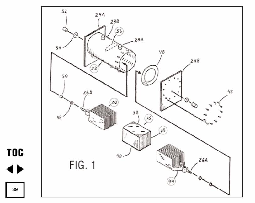
Figure 1 (next page) is an exploded view of the basic one cell electrolyz-er. You can see in the drawing that it is simple in construction. It consists ofa positive and negative electrodes #44 and #20, a separator box #16, withina pressure retaining housing #22.
Water Electrolyzers
38
39
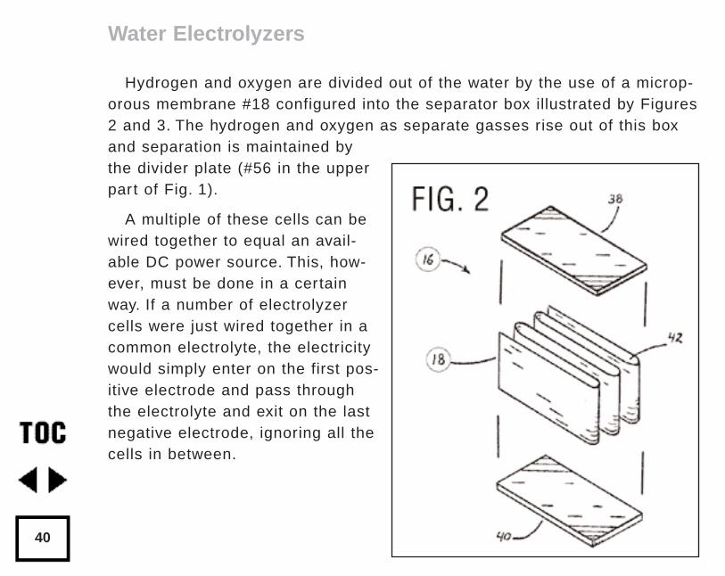
Hydrogen and oxygen are divided out of the water by the use of a microp-orous membrane #18 configured into the separator box illustrated by Figures2 and 3. The hydrogen and oxygen as separate gasses rise out of this boxand separation is maintained bythe divider plate (#56 in the upperpart of Fig. 1).
A multiple of these cells can bewired together to equal an avail-able DC power source. This, how-ever, must be done in a certainway. If a number of electrolyzercells were just wired together in acommon electrolyte, the electricitywould simply enter on the first pos-itive electrode and pass throughthe electrolyte and exit on the lastnegative electrode, ignoring all thecells in between.
Water Electrolyzers
40
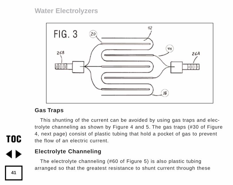
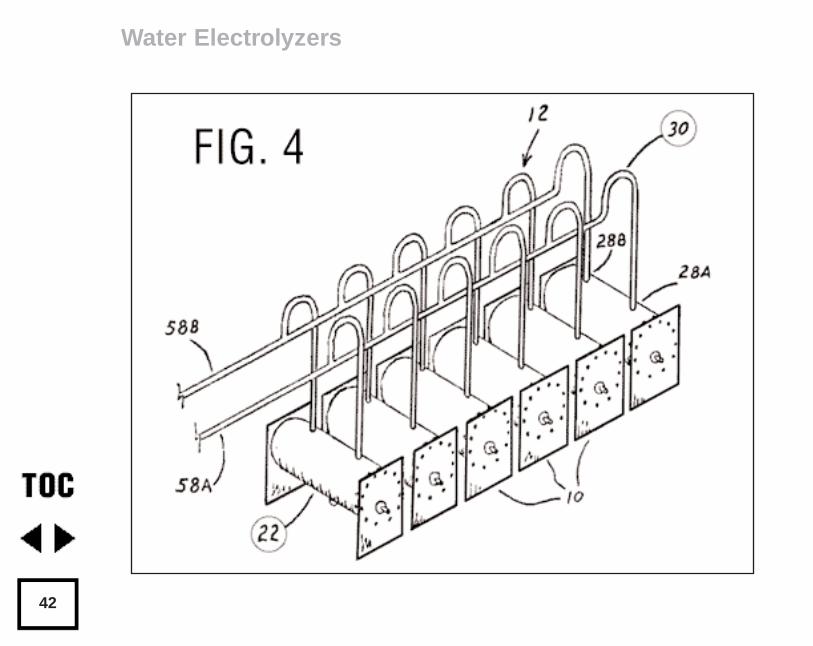
Gas Traps
This shunting of the current can be avoided by using gas traps and elec-trolyte channeling as shown by Figure 4 and 5. The gas traps (#30 of Figure4, next page) consist of plastic tubing that hold a pocket of gas to preventthe flow of an electric current.
Electrolyte Channeling
The electrolyte channeling (#60 of Figure 5) is also plastic tubingarranged so that the greatest resistance to shunt current through these
Water Electrolyzers
41
Water Electrolyzers
42
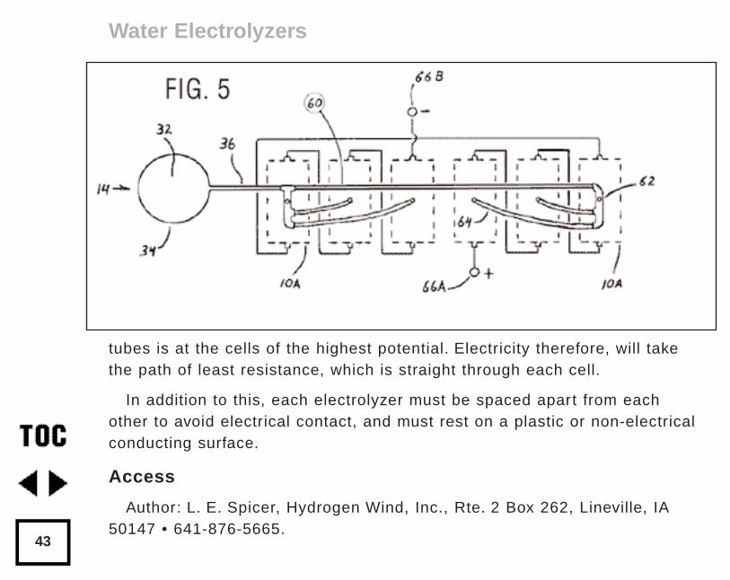
tubes is at the cells of the highest potential. Electricity therefore, will takethe path of least resistance, which is straight through each cell.
In addition to this, each electrolyzer must be spaced apart from eachother to avoid electrical contact, and must rest on a plastic or non-electricalconducting surface.
Access
Author: L. E. Spicer, Hydrogen Wind, Inc., Rte. 2 Box 262, Lineville, IA50147 • 641-876-5665.
Water Electrolyzers
43
by Walt Pyle, Jim Healy, Reynaldo CortezOriginally published in Home Power #39 • February / March 1994 ©1994 Walt Pyle, Jim Healy, Reynaldo Cortez
Why would anyone want to produce hydrogen at home? Hydrogen can beused as a non-toxic energy storage and transport medium. Hydrogen that ismade from water using solar energy is a sustainable and renewable homeenergy supply. Make hay (or hydrogen) while the sun shines. Then use thestored hydrogen to produce heat and electricity on demand, day or night!We got excited about solar hydrogen production during the seventies andthe first oil shocks.
What happened between the seventies and nineties? For the most part weworked with thermolysis (splitting water with concentrated solar heat) andphotoelectrolysis (splitting water in a liquid solar cell). We also followed thework of other hydrogen pioneers, such as Roger Billings and his associates,who produced and used hydrogen in home appliances and vehicles. Thearticle by Richard Perez about the Schatz PV Hydrogen Project (p. 20) anda subsequent visit to Humboldt State University’s Trinidad Marine Laboratorylaunched us into designing and making a “home-sized” system based onelectrolysis of water. Electrolysis is the competition for thermolysis and pho-
Solar Hydrogen Production by Electrolysis
44
toelectrolysis at this juncture. Hydrogen and oxygen can be produced fromwater using electricity with an electrolyzer.
This article describes the installation and operation of a 12 cell HydrogenWind Inc. 1000 Watt electrolyzer. This electrolyzer can produce 170liters/hour (6 cubic feet/hour) of hydrogen and 85 liters/hour (3 cubicfeet/hour) of oxygen (at standard temperature and pressure). In addition, wedescribe a homebrew purification and storage system for the hydrogen andoxygen produced by the electrolyzer. With proper after-treatment, the gasesproduced can be stored safely. The purified hydrogen and oxygen can beused in fuel cells (to produce direct current electricity) and catalytic burners(for heating and cooking) without poisoning or damaging the noble metalcatalyst materials. The gases can also be used for welding and cutting, aswell as for motor vehicle fuel.
!!!!Safety First!!!!
Making and storing hydrogen and oxygen is not kid’s stuff - this is “rocketfuel”! Use flashback flame arrestors on the hydrogen and oxygen outletsfrom the electrolyzer. Secure dangerous caustic from small prying hands.Make sure your gases are pure before storing them. More on safety follows.
Solar Hydrogen Production by Electrolysis
45
How Much Hydrogen Do I Need?
This varies tremendously from household to household, depending on howwell the Demand Side Management job has been done. We can run ourPlatinum Cat space heater for about three hours on a cubic meter of hydro-gen. The amount of gas needed can be estimated from the energy consump-tion of any appliance. Amanda Potter and Mark Newell’s article (HydrogenBasics, p.8) describes the operation of an electrolyzer and shows how to cal-culate the amount of gas needed to run appliances. See the chapters onhydrogen space heating (p.143), hydrogen cooking (p.118 and 129), andmaking electricity from hydrogen with a fuel cell (p.169).
How Much Power Does It Take?
A cubic meter (35.3 cubic feet) of hydrogen gas takes about 5.9 hours toproduce in this electrolyzer, when operated at its rated input power of 1000Watts. This means the energy required to produce a cubic meter of hydrogenand 0.5 cubic meter of oxygen is about 5.9 kW-hr. This translates to an effi-ciency of 51%, where 3 kW-hr/m 3 equals 100% efficiency at 20°C. Typicalindustrial scale plants operate at about 4.5 kW-hr/m 3 or 67% efficiency athigh current density. The efficiency is better at lower current density.
Solar Hydrogen Production by Electrolysis
46
What Is Needed to Produce Hydrogen at Home?
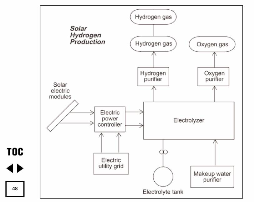
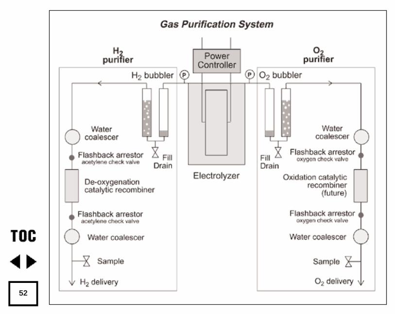
Our system includes the following components and sub-systems (see theblock diagram next page):
• Solar electric power and/or utility grid power
• Power Controller
• Electrolyzer
• Hydrogen Purifier
• Oxygen Purifier
• Hydrogen and Oxygen Storage Tanks
• Electrolyte Storage Tank and Transfer Pump
• Makeup-water Purifier
Where Can I Get An Electrolyzer?
The Hydrogen Wind electrolyzer is introduced by its designer Lawrence Spicerin the previous chapters “Hydrogen Fuel” (p.32). Hydrogen Wind Inc. electrolyz-ers are available in single cell units for small demand or educational use, and inmultiple cell configurations which provide higher gas production rates.
We purchased a 12 cell 1000 Watt system with the gas pressure controls andelectrical metering. Larger systems with up to 24 cells or smaller three cell andsix cell systems are available. Another article by Spicer, “Water Electrolyzers,”(p.38), describes the individual cells in more detail along with an introduction tocell arrays.
Solar Hydrogen Production by Electrolysis
47
48
The cell electrodes are fabricated from rectangular metal plates with tabson one end. Both the anode and the cathode metal plates are made fromporous, sintered nickel. Two clusters of nickel electrode plates, 14 for theanode and 14 for the cathode, are separated by porous plastic sheets foldedaccordion style within a separator container.
The plastic separator container is open at the horizontal ends, and closedat the top and bottom. This lets the larger hydrogen gas bubbles (whichescape from the negative electrode or cathode) rise in the electrolyte, due totheir buoyancy, and exit the separator container on one side. The hydrogenremains separate from the smaller oxygen bubbles which evolve from thepositive electrode (anode) and exit on the opposite side.
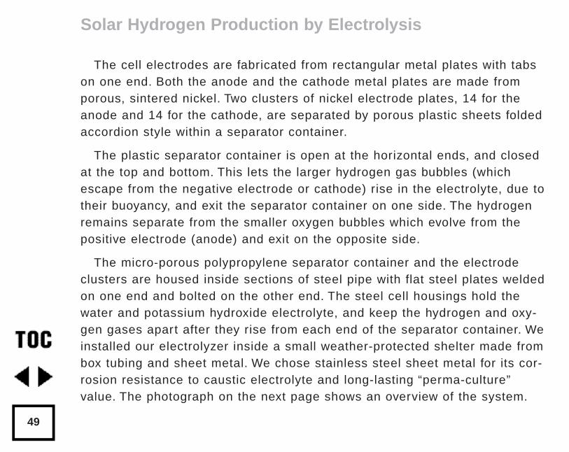
The micro-porous polypropylene separator container and the electrodeclusters are housed inside sections of steel pipe with flat steel plates weldedon one end and bolted on the other end. The steel cell housings hold thewater and potassium hydroxide electrolyte, and keep the hydrogen and oxy-gen gases apart after they rise from each end of the separator container. Weinstalled our electrolyzer inside a small weather-protected shelter made frombox tubing and sheet metal. We chose stainless steel sheet metal for its cor-rosion resistance to caustic electrolyte and long-lasting “perma-culture”value. The photograph on the next page shows an overview of the system.
Solar Hydrogen Production by Electrolysis
49
Solar Power andUtility Grid BackupPower
Our solar electric poweris produced by two 16-panel Carrizo Solar “Mud”photovoltaic arrays and agaggle of other smallerpanels. On a good sum-mer day we get up to 75Amperes at 14 Volts forcharging the house batter-ies. When the two housebattery banks are fullycharged, our two 50 AmpSCI charge controllers dis-connect the PV power, andthe PV voltage rises. AnEnermaxer controllersenses the voltage riseand transfers the PV
Solar Hydrogen Production by Electrolysis
50
An overview of the electrolyzer system. Thepower supplies and electrical controls are on
the far left. Purification equipment is to the rightof the power controls. The electrolyte reservoir
and hydrogen and oxygen float valves with pres-sure gauges are to the right of the purificationequipment. Twelve electrolyzer cells are shown
on the far right. A feedwater purification systemis just below the twelve electrolyzer cells. The
caustic electrolyte storage tank is on the groundbelow the float valves.
Photo by Reynaldo Cortez
power to the electrolyzers to make hydrogen and oxygen during the remain-der of the day. A utility grid electrolyzer power supply is used to makehydrogen and oxygen when there is insufficient solar power available.
How Do We Purify the Gases?
The gas purification system is shown in more detail in the diagram onnext page. The hydrogen gas and the oxygen gas are purified by two differ-ent systems.
Bubblers
First, each gas is scrubbed by passing it through a water bubbler column.Each of the gas scrubbing bubblers is made from two vertical plastic tubeswith end caps. A pair of fish-aquarium type bubbler frits was glued intoholes drilled in the inside bottom caps of each acrylic plastic tube, usingmethylene chloride solvent. Flow of gas into or out of a bubbler can then beseen by the operator. The bubblers are filled about one-third full with dis-tilled water using the drain and fill valves on the bottoms. We call these “Bi-directional Bubblers”. The bubblers are tolerant of flow in any direction, with-out letting the scrub-water into the product storage system or the electrolyz-er. We got the idea for making these bubblers from Dr. Peter Lehman andhis associates at Humboldt State University (Schatz Solar Hydrogen andFuel Cell Laboratory.)
Solar Hydrogen Production by Electrolysis
51
52
The gases entering the purifier are saturated with water vapor and maycontain minute amounts of caustic electrolyte aerosol and particulates likerust. After passing through the bubblers the gases are still saturated withwater vapor, but vir tually caustic- and particulate-free. Installing anothercoalescer before the bubbler would prevent particulates and some aerosolfrom entering the bubblers.
Coalescers
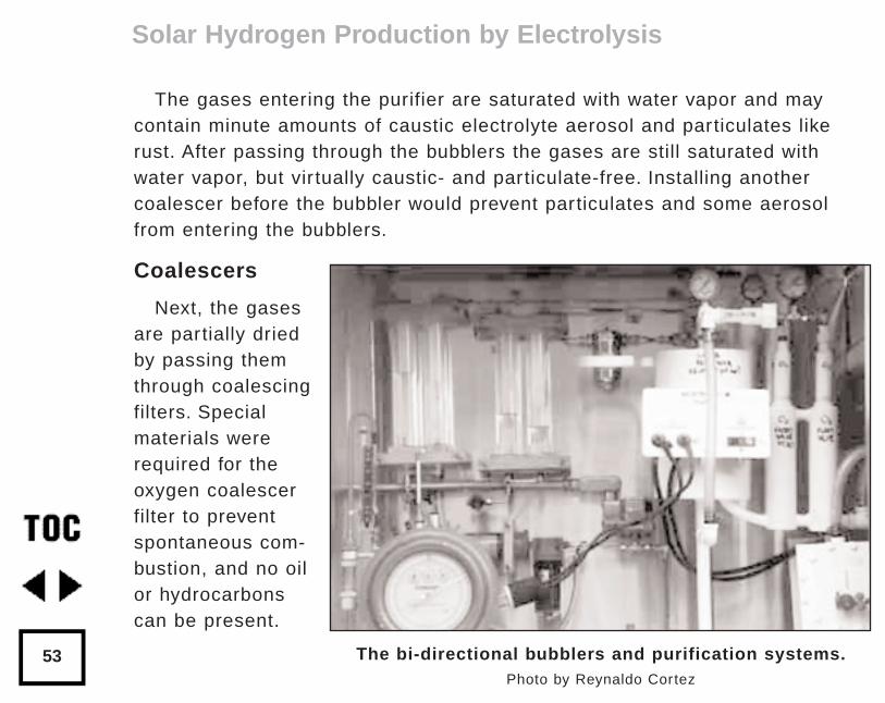
Next, the gasesare partially driedby passing themthrough coalescingfilters. Specialmaterials wererequired for theoxygen coalescerfilter to preventspontaneous com-bustion, and no oilor hydrocarbonscan be present.
Solar Hydrogen Production by Electrolysis
53 The bi-directional bubblers and purification systems.Photo by Reynaldo Cortez
Recombiners
The hydrogen gas purifier treats the hydrogen gas in a catalytic recom-biner. The purpose of the recombiner is to recombine any oxygen impurityin the hydrogen product, and make water. The noble metal catalytic recom-biner removes the oxygen impurity to make the hydrogen gas safe to storeand handle. As a safety measure, we installed flashback arrestors betweenthe first and second coalescers and the recombiners. The flashbackarrestors prevent flashback of poor purity gases (oxygen impurity in thehydrogen produced) when they reach the recombiner and ignition source.The recombiners must be installed with their major axis vertical and theentry at the top.
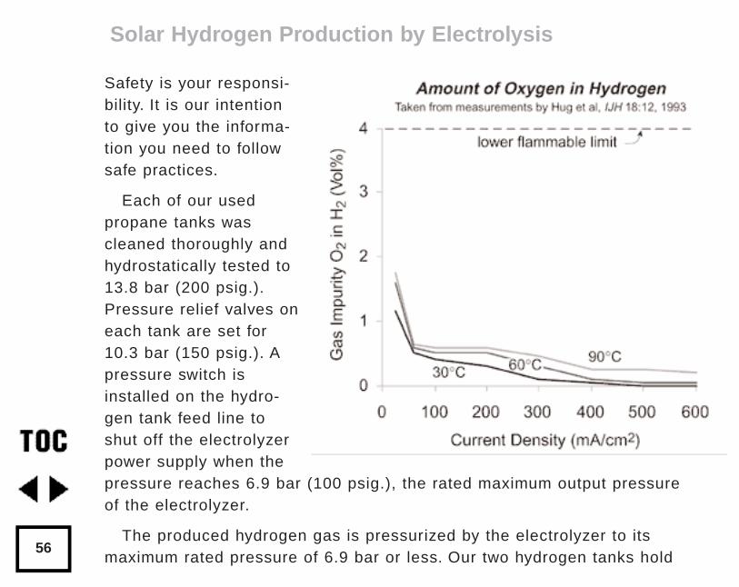
Some data recently published by W. Hug et al from the GermanAerospace Research Establishment (International Journal of HydrogenEnergy, Vol. 18 No. 12, pp. 973-977) shows that purity of the gases pro-duced by an alkaline electrolyzer is affected by the current density andtemperature of the cells. From the graphs (next pages) we see that thepurities of the hydrogen and oxygen gases are poorer at low current densi-ties (such as when a cloud covers the sun for example). This is becausediffusion of the gases through the liquid electrolyte is a more significantfraction of the total production at low current densities.
Solar Hydrogen Production by Electrolysis
54
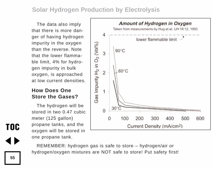
The data also implythat there is more dan-ger of having hydrogenimpurity in the oxygenthan the reverse. Notethat the lower flamma-ble limit, 4% for hydro-gen impurity in bulkoxygen, is approachedat low current densities.
How Does OneStore the Gases?
The hydrogen will bestored in two 0.47 cubicmeter (125 gallon)propane tanks, and theoxygen will be stored inone propane tank.
REMEMBER: hydrogen gas is safe to store – hydrogen/air orhydrogen/oxygen mixtures are NOT safe to store! Put safety first!
Solar Hydrogen Production by Electrolysis
55
Safety is your responsi-bility. It is our intentionto give you the informa-tion you need to followsafe practices.
Each of our usedpropane tanks wascleaned thoroughly andhydrostatically tested to13.8 bar (200 psig.).Pressure relief valves oneach tank are set for10.3 bar (150 psig.). Apressure switch isinstalled on the hydro-gen tank feed line toshut off the electrolyzerpower supply when thepressure reaches 6.9 bar (100 psig.), the rated maximum output pressureof the electrolyzer.
The produced hydrogen gas is pressurized by the electrolyzer to itsmaximum rated pressure of 6.9 bar or less. Our two hydrogen tanks hold
Solar Hydrogen Production by Electrolysis
56
the equivalent of: 6.9 bar x 2 tanks x 0.47 cubic meter = 6.5 cubic meters (atstandard temperature and 6.9 bar pressure).
Makeup-water Treatment System
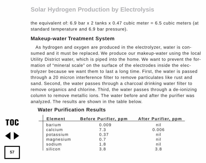
As hydrogen and oxygen are produced in the electrolyzer, water is con-sumed and it must be replaced. We produce our makeup-water using the localUtility District water, which is piped into the home. We want to prevent the for-mation of “mineral scale” on the surface of the electrodes inside the elec-trolyzer because we want them to last a long time. First, the water is passedthrough a 20 micron interference filter to remove particulates like rust andsand. Second, the water passes through a charcoal drinking water filter toremove organics and chlorine. Third, the water passes through a de-ionizingcolumn to remove metallic ions. The water before and after the purifier wasanalyzed. The results are shown in the table below.
Solar Hydrogen Production by Electrolysis
57
Water Purification Results
Element Before Puri f ier, ppm After Puri f ier, ppm
bar ium 0.009 n i l ca lc ium 7.3 0.006 potass ium 0.37 n i l magnesium 0.7 n i l sod ium 1.8 n i l s i l icon 3.8 3.8
As you can see, we removed some scale-forming material. Other elementswere below the lower detectable level of the instrument (approximately oneppb). Our water before the deionizer and charcoal filter is not very “hard” atthis location; it does not contain very many dissolved minerals. After the de-ionizer there is a marked reduction in elemental concentrations of every-thing except silicon.
Why Conduct a Hydrostatic Test on the Electrolyzer?
Prior to filling the electrolyzer with caustic electrolyte, we conducted ahydrostatic leak test by filling the cells with purified water and pressurizingthe cells and electrolyte reservoir to 6.9 bar (100 psig) using utility linepressure. Several tubing fittings leaked until tightened. Fixing water leaksduring the initial hydrostatic test is much better than fixing leaks when theyinvolve caustic electrolyte! Getting caustic on your tools, gloves, safetyglasses, and clothes is a real drag. Plan ahead! When installing the tubingclamps, position them so you can tighten them later when the cells are tiedtogether. An improvement would be to mount the cells higher to allow foraccess to the clamps from below.
Solar Hydrogen Production by Electrolysis
58
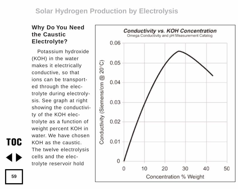
Why Do You Needthe CausticElectrolyte?
Potassium hydroxide(KOH) in the watermakes it electricallyconductive, so thations can be transport-ed through the elec-trolyte during electroly-sis. See graph at rightshowing the conductivi-ty of the KOH elec-trolyte as a function ofweight percent KOH inwater. We have chosenKOH as the caustic.The twelve electrolysiscells and the elec-trolyte reservoir hold
Solar Hydrogen Production by Electrolysis
59
about 61 liters (16 gallons) of water plus 15 kilograms (33 pounds) of KOH.This solution is about 23% KOH
Safety is a Must When Handling Caustic Electrolyte!
DANGER!! Potassium hydroxide is very corrosive and hazardous to handle.KOH deserves great respect. Goggles or safety glasses with side protectors,and plastic or rubber gloves are absolutely necessary when handling KOH.When caustic comes into contact with the skin, the natural oils of the skinare chemically converted to a soap, which initially gives a slippery feeling.Prolonged contact will dissolve the skin and give a chemical burn similar butmore severe than that given by handling lime or fresh wet concrete with barehands. The best treatment for any accidental spill is flushing with copiousamounts of water, or neutralization with a weak acid such as vinegar. Alwayshave a water hose hooked up and operational before handling KOH caustic.Keep the electrolyzer outdoors and locked so only qualified people can serv-ice it. A cyclone fence with top and sides might be the solution.
DANGER!! The mucous membranes of the eye are especially susceptibleto caustic damage. It has been estimated that 15 seconds of contact to theeye with concentrated KOH caustic is enough to produce permanent blind-ness. If any KOH comes into contact with the eyes, the best treatment is toflush the eyes immediately with pure water for at least 15 minutes and seekmedical attention.
Solar Hydrogen Production by Electrolysis
60
What Provisions Need to be Considered When Handling Caustic?
To service any of the cells, we need a way to drain the electrolyte andstore it for re-use. We have a drain valve and line on the bottom of the elec-trolyte reservoir that allows the KOH solution to gravity drop into a stainlesssteel tank at a lower level on the ground. A tubing roller pump is used torefill the electrolyzer cells with KOH after the maintenance is completed. OurKOH tank was previously used as a swimming pool filter case.
We mixed the water and KOH in the ground level caustic storage tank.Water and KOH mixing produces chemical heat, the “heat of solution”, whichis surprisingly high. After we mixed in all of the KOH flakes, the water tem-perature rose from 20°C (68°F) to about 82°C (180°F).
At this point we made our first big mistake. After the KOH and water elec-trolyte solution was mixed (and hot), we immediately started pumping it intothe electrolyzer reservoir and cells, using the tubing pump. Within minutes,the tubing pump began leaking. We stopped the pump and drained the KOHback to the ground level tank. After cleaning up the mess, we found that thesilicone tubing had split open. We let the KOH solution cool overnight. Thenext day we replaced the tubing in the pump, and tried again. This time thetransfer proceeded without pump tubing problems.
Solar Hydrogen Production by Electrolysis
61
By the time the caustic was about half pumped into the cells, we foundthat six of the tubing fittings on the first two cells were dripping KOH ontothe floor of the shelter. The hot KOH the night before had damaged some ofthe pipe thread seals which were made with five minute epoxy. The threadsin cells further away from the caustic KOH entry point were not damaged,presumably because the caustic KOH solution had cooled by the time itreached those points. We drained the caustic KOH back to the ground stor-age tank, removed the affected fittings and replaced the epoxy threadsealant. The next day we filled the cells back up with KOH solution for thethird try.
More caustic KOH leaks! This time we had leaks on the tubing fittings onthe gas-trap tubing loops where the hydrogen and oxygen come out of thecells at the top. Additional tightening of the tubing clamps with a 12 pointbox wrench stopped some leaks. Other fittings had to be removed andthread epoxy had to be reapplied. When will solid polymer electrolyte elec-trolyzer cells be available at a reasonable price so we won’t have to hasslewith KOH???
What Were the Cell Operating Conditions?
The cells require about 1.7 volts each to begin operating; at higher cur-rents there is a greater voltage requirement. The direct current requirement
Solar Hydrogen Production by Electrolysis
62
is about 40 Amperes for each cell at rated gas output. In a twelve-cell sys-tem the cells are wired in series, so that all of the cells get the same currentand the voltages add up to 12 x 1.7 V or 20.4 Volts total at 20 Amperes ofcurrent. The cells can also be wired in series-parallel for 10.2 Volts total.
Our solar photovoltaic system and grid back-up power supplies can onlyproduce about 25 Amperes at the moment, so we cannot yet achieve fullgas output. The 20.4 Volt operating voltage was not a problem with ourCarrizo solar electric arrays, however, since they have an open circuit volt-age of about 25 Volts.
Strange and Unusual Behavior?
When operating the electrolyzer the first day on direct current power, thepower controller behaved predictably. We measured about 22 Volts and 25Amperes flowing into the electrolyzer cells. We had gas flow only throughthe oxygen bubbler however!! And occasionally, the oxygen float valve“burped” some KOH solution upward with a release of gas. The fix for thisproblem was to raise the electrolyte level from about 5 cm (2 inch) on thereservoir level gauge to 20 cm (8 inch).
At first startup, the gas comes out after a delay of about an hour while thecells are “charging” and the gas bubbles on the electrodes get large enough
Solar Hydrogen Production by Electrolysis
63
to break away. Voltage across the cell array gradually rises during “charging”from 18 to 19 to 20 Volts before gas comes out.
On restart, hydrogen comes out later than oxygen since it must first fillthe top of the electrolyte reservoir tank to pressure-pump the system. Whenboth gases were coming out of the electrolyzer pressure control float valves,the pressure on the reservoir was 2.5 bar (36 psig) when discharging toatmospheric pressure.
The next day we may have had our first personal demonstration of WilliamGrove’s astonishing observation that an electrolyzer can run backwards andbecome a power source. Grove discovered in the early 19th century that thereverse reaction - supplying oxygen and hydrogen to electrodes - causes anelectrolyzer to produce direct current electricity and act as a fuel cell.
Before we turned on our power supply the next day, the voltmeter showedabout 16 Volts DC on the electrolyzer terminals indicating it was acting as a“source”. After that we put a resistive load on the electrolyzer leads andgenerated about 16 Volts and 10 Amps for several hours (160 Watts) beforeit “ran out of gas”. Was the cell acting as a fuel cell, as an alkaline nickel-iron battery, or a combination of both?
Solar Hydrogen Production by Electrolysis
64
Grunting and Wheezing Sounds are Normal!
Inside the Hydrogen Wind gas pressure control system there are threefloat control valves. Two float valves are used for the oxygen and one isused for the hydrogen. When the float valves are filled with gas (verticalacrylic tubes with top caps), they float on the electrolyte in the chambers.As each chamber fills with gas the electrolyte is gradually displaced and thethe buoyancy of the float decreases. When the buoyancy is low enough, thefloat falls, which releases the elastomer plug from the exit passage andallows the gas to leave the system. The float valves cycle over and overagain to release “bursts” of gas to the purifiers. You can hear grunting andwheezing sounds when standing alongside the unit. A little back pressure onthe discharge lines makes the release less violent and quieter. With 1 bar(14.5 psig) back pressure we had good results.
Budget & Economics for Gas Production & Storage
The approximate cost for the solar hydrogen system equipment is listedon the next page, broken down by sub-system. The labor used for this instal-lation was our own and was not tallied. Normally, for a “first time” systemsuch as this, a rule of thumb is that the labor costs will about equal the cap-ital equipment costs. Labor on any future clone would be significantly less.
Solar Hydrogen Production by Electrolysis
65
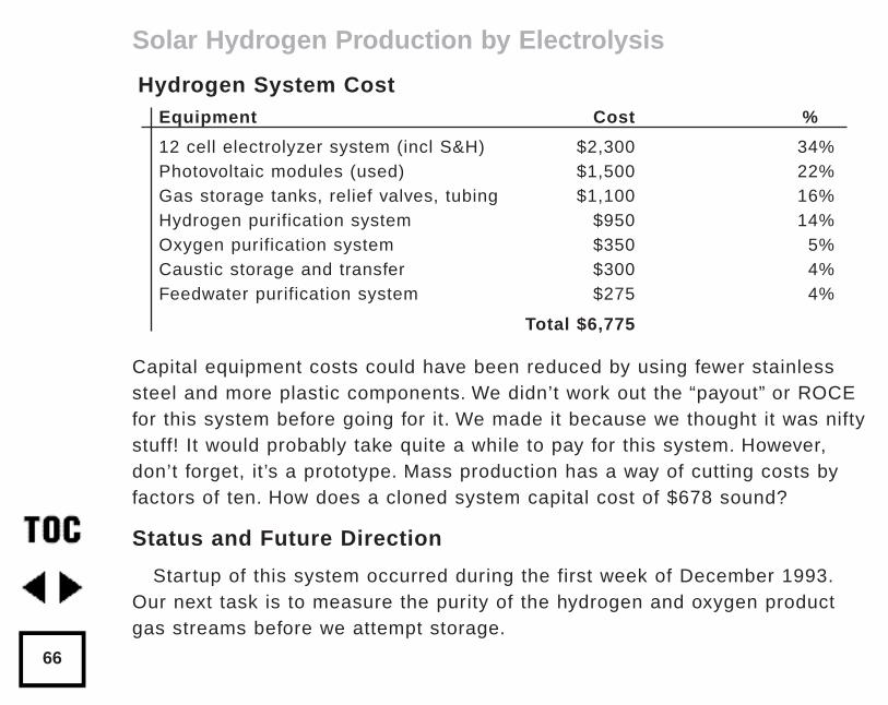
Capital equipment costs could have been reduced by using fewer stainlesssteel and more plastic components. We didn’t work out the “payout” or ROCEfor this system before going for it. We made it because we thought it was niftystuff! It would probably take quite a while to pay for this system. However,don’t forget, it’s a prototype. Mass production has a way of cutting costs byfactors of ten. How does a cloned system capital cost of $678 sound?
Status and Future Direction
Startup of this system occurred during the first week of December 1993.Our next task is to measure the purity of the hydrogen and oxygen productgas streams before we attempt storage.
Solar Hydrogen Production by Electrolysis
66
Hydrogen System CostEquipment Cost %
12 cell electrolyzer system (incl S&H) $2,300 34%Photovoltaic modules (used) $1,500 22% Gas storage tanks, relief valves, tubing $1,100 16%Hydrogen purification system $950 14% Oxygen purification system $350 5%Caustic storage and transfer $300 4%Feedwater purification system $275 4%
Total $6,775
Eventually, when we have a use for the oxygen gas product in a large fuelcell, we plan to add an oxidation recombiner to the oxygen side. This willremove any hydrogen impurity from the oxygen side and make it safe tostore and handle. For now, we are not storing the oxygen. Instead, we willsupply the oxygen to the root system of vegetables in some experimentswith a horticultural friend of ours, but that’s another story...
A future article will focus on safe storage of hydrogen and oxygen (see“Hydrogen Storage,” p.95 and “Hydrogen Purification,” p.69). We plan tocover compressed hydrogen and oxygen gas storage and hydrogen storagein metal hydride.
Acknowledgements
Alternative Energy Engineering, David Booth and David Katz, for theupgrade to our Enermaxer power controller.
Jim Robbers and Mike Robbers for the used stainless steel swimming poolfilter cases which we use for electrolyte storage.
Access
Walt Pyle, WA6DUR, Richmond, CA • 510-237-7877
Jim Healy, WH6LZ, Richmond, CA • 510-236-6745
Reynaldo Cortez, Richmond, CA • 510-237-9748
Solar Hydrogen Production by Electrolysis
67
ElectrolyzerHydrogen Wind Inc. RR 2 Box 262, Lineville, IA 50147 • 515-876-5665
Purifier and Storage Components Hydrogen Coalescer (Coilhose 27C3-S): Weill Industrial Supply Inc.
FAX 510-235-2405
Bi-directional Bubbler: H-Ion Solar Co. • FAX 510-232- 5251
Flame Arrestors: Check valve flashback arrestor, flash arrestor body withfemale inlet check valve. Part # FA-3CV. Western Enterprises • FAX216-835-8283
Purifier and Storage Components (continued) Oxygen Coalescer Finite Housing S2M-2C10-025: A F Equipment Co.
408-734-2525
Hydrogen Recombiner Deoxo Purifier D50-1000: GPT Inc.FAX 908-446-2402
Pressure Relief Valves (Nupro 177-R3A-K1-A): Oakland Valve & FittingCo. • FAX 510-798-9833
Power SourcesSolar arrays: Carrizo Solar Corp. • 800-776-6718
Enermaxer controller: Alternative Energy Engineering • 800-777-660
Solar Hydrogen Production by Electrolysis
68
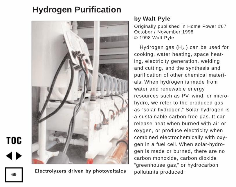
by Walt PyleOriginally published in Home Power #67October / November 1998© 1998 Walt Pyle
Hydrogen gas (H2 ) can be used forcooking, water heating, space heat-ing, electricity generation, weldingand cutting, and the synthesis andpurification of other chemical materi-als. When hydrogen is made fromwater and renewable energyresources such as PV, wind, or micro-hydro, we refer to the produced gasas “solar-hydrogen.” Solar-hydrogen isa sustainable carbon-free gas. It canrelease heat when burned with air oroxygen, or produce electricity whencombined electrochemically with oxy-gen in a fuel cell. When solar-hydro-gen is made or burned, there are nocarbon monoxide, carbon dioxide“greenhouse gas,” or hydrocarbonpollutants produced.
Hydrogen Purification
69Electrolyzers driven by photovoltaics
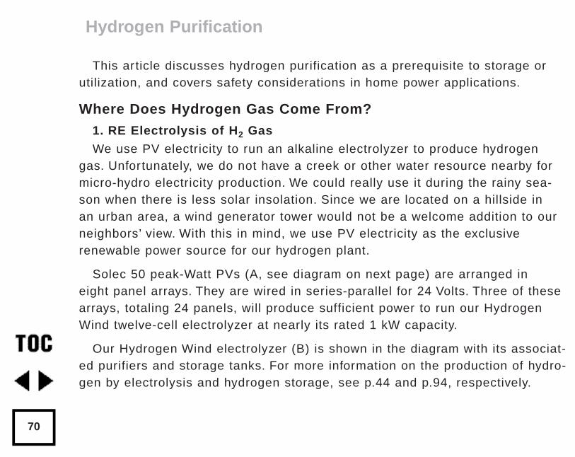
This article discusses hydrogen purification as a prerequisite to storage orutilization, and covers safety considerations in home power applications.
Where Does Hydrogen Gas Come From?1. RE Electrolysis of H2 Gas
We use PV electricity to run an alkaline electrolyzer to produce hydrogengas. Unfortunately, we do not have a creek or other water resource nearby formicro-hydro electricity production. We could really use it during the rainy sea-son when there is less solar insolation. Since we are located on a hillside in an urban area, a wind generator tower would not be a welcome addition to ourneighbors’ view. With this in mind, we use PV electricity as the exclusive renewable power source for our hydrogen plant.
Solec 50 peak-Watt PVs (A, see diagram on next page) are arranged in eight panel arrays. They are wired in series-parallel for 24 Volts. Three of thesearrays, totaling 24 panels, will produce sufficient power to run our HydrogenWind twelve-cell electrolyzer at nearly its rated 1 kW capacity.
Our Hydrogen Wind electrolyzer (B) is shown in the diagram with its associat-ed purifiers and storage tanks. For more information on the production of hydro-gen by electrolysis and hydrogen storage, see p.44 and p.94, respectively.
Hydrogen Purification
70
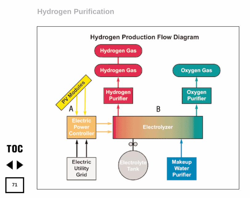
Hydrogen Purification
71
2. Industrial Cylinder H2 Gas
We can buy hydrogen gas in high pressure cylinders from a welding sup-ply house. The industrial grade is about 99.5+% pure hydrogen. It may havea few parts per million of hydrocarbons, water vapor, helium, oxygen, andnitrogen contaminants present. These cylinders come in four volumetricsizes, and have 120 to 240 bar (1800 to 3500 psig) pressure ratings. Themost common cylinder size is six cubic meters (215 cubic feet). Most indus-trial hydrogen is made by steam-reforming natural gas.
In the past, we bought hydrogen cylinders and used them in our shop.Now that we make our own gas, we rarely have to purchase it.
3. High Purity Industrial H2
There are several higher purity grades of hydrogen available for researchand metallurgical processing purposes, when contaminants must be mini-mized. One is the “pre-purified grade” with minimum purity of 99.95%. Thisgrade contains less than 20 ppm oxygen with a dew point of less than -59°C(-75°F). This quality of hydrogen is often referred to as “3-nines.”
Another high-purity hydrogen, the “ultra-high purity (Gold Label) grade,”provides 99.999% molecular hydrogen. Sometimes this is called “5-nines”purity. For those who demand the best, there is “Research Grade”. Thisgrade has even fewer impurities, and is available in small lecture bottles.
Hydrogen Purification
72
4. Cryogenic Liquid H2
Liquid hydrogen is primarily used as rocket fuel or for large industrialsites. The only significant impurity is helium. We have never used liquidhydrogen for home applications, because special tanks are required. Thecryogenic tanks have dual walls. The space between the walls is evacuatedand filled with radiation reflective multi-layer insulation. Some experimentalcars have been run on liquid hydrogen.
6. Common-duct Hydrogen-Oxygen
Common-duct hydrogen-oxygen welding gas is commonly referred to aseither Rhodes’ gas or Brown’s gas. This gas consists of hydrogen thatcomes from a “common-duct” electrolyzer, mixed with oxygen. It is VERYdangerous. H2 + O2 mixtures should NEVER be stored. Common-duct elec-trolyzer hydrogen is not suitable for use in hydrogen fuel cells, catalyticheaters, or diffusion burners.
The only sensible application for common-duct hydrogen is to run weldingand cutting torches. When it is used in this manner, there is no storage andthe gas is consumed as it is made.
Hydrogen Purification
73
What Contaminants May Be Present in H2?1. Solid Particulate Contaminants in H2 Gas
It is possible to find entrained particles of dir t and rust in a hydrogenelectrolyzer’s product stream. Some electrolyzers have steel or iron alloycontainers, valves, and piping. This metal may produce low levels of rustparticles over time. Electrolyzers frequently use high surface area electrodematerials such as nickel that may lose small particles into the electrolyte.Sometimes, particles of either plastic or sealant will enter the electrolytesystem. This happens due to poor housekeeping during manufacturing orrepair. These particulates can be removed from your hydrogen gas streamwith an appropriate scrubber or filter.
2. Liquid Contaminants in H2 Gas
Electrolyte is the normal liquid contaminant in an alkaline electrolysis sys-tem. In this case, it is water plus potassium hydroxide (KOH). A smallamount of KOH and water escapes from the electrolyzer with the flow ofhydrogen. An aerosol of fine electrolyte droplets is produced as bubbles ofhydrogen gas rise to the surface of the liquid electrolyte and then pop. Thesame thing happens on the oxygen side of the electrolyzer.
Hydrogen Purification
74
In our Hydrogen Wind electrolyzer, there is another source of KOH/wateraerosol hydrogen contamination: electrolyte-wetted float valves that controlthe discharge of gas from the unit. Any other liquid contaminant in thehydrogen gas would be unexpected. A coalescing filter can remove solidsand liquid KOH/water aerosol droplets.
3. Gaseous Contaminants in H2 Gas
Under certain conditions, we find gaseous contaminants such as oxygen,nitrogen, argon, and water vapor in our hydrogen gas.
Oxygen, nitrogen, and argon are present in normal air. When all three ofthese gases are present in the normal proportions, an air leak into the elec-trolyzer or its piping has occurred. However, this is rare. Usually, this is seenonly at startup of the electrolyzer when purging or evacuation is imperfect. Italso can happen when there are significant leaks in either the cells or in theinterconnecting piping. Once the electrolyzer is operating above atmosphericpressure, no outside air will leak inside. However, some hazardous elec-trolyte may leak out if there are any poor seals. See the chapter “SolarHydrogen Production by Electrolysis” p. 44 for safety information about han-dling alkaline electrolyte, as KOH is very corrosive to skin and eyes.Nitrogen and argon are not a safety concern, as they are inert gases.Oxygen is the contaminant of primary concern.
Hydrogen Purification
75
Water vapor is always present in a KOH/water electrolyzer. The gasvapor space of each cell is saturated with water above the electrolyte.The concentration of water saturation is governed by the temperature andpressure in that environment. The objective in a purifier system is toremove excess water vapor. This prevents condensation from occuringdownstream, with subsequent flooding of other components. The pres-ence of some water vapor in hydrogen that has been purified for storagein pressure tanks is not harmful - as long as a compressor is not used.The presence of water vapor in stored hydrogen gas slightly reduces itsflammable limits in oxygen or air. Our electrolyzer produces gas underpressure, between 0.1 and 4 bar (1 to 58 psig), depending on storagetank pressure.
What are the Methods for Purifying H 2 ?1. Scrubbers for Particulate and KOH Removal
Hydrogen gas that is contaminated by KOH/water electrolyte can bescrubbed by passing it through a water column in a Double-Bubbler TM(photo next page, and C in the diagram on page 85) to remove the KOH.
2. Catalytic Recombination Purifier to Remove O2 Impurity
The catalytic recombination of hydrogen and contaminant oxygenis usually accomplished at room temperature or higher, and results in
Hydrogen Purification
76
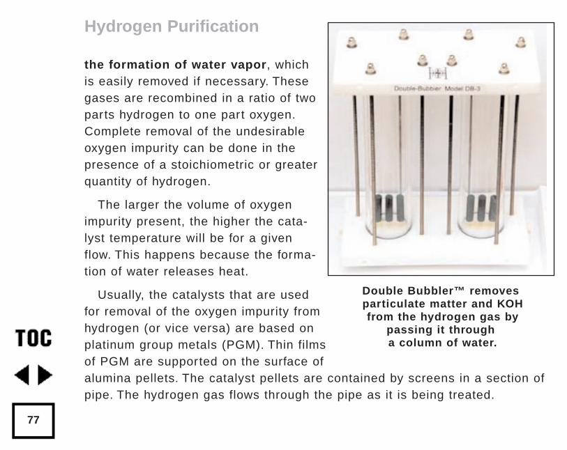
the formation of water vapor, whichis easily removed if necessary. Thesegases are recombined in a ratio of twoparts hydrogen to one part oxygen.Complete removal of the undesirableoxygen impurity can be done in thepresence of a stoichiometric or greaterquantity of hydrogen.
The larger the volume of oxygenimpurity present, the higher the cata-lyst temperature will be for a givenflow. This happens because the forma-tion of water releases heat.
Usually, the catalysts that are usedfor removal of the oxygen impurity fromhydrogen (or vice versa) are based onplatinum group metals (PGM). Thin filmsof PGM are supported on the surface ofalumina pellets. The catalyst pellets are contained by screens in a section ofpipe. The hydrogen gas flows through the pipe as it is being treated.
Hydrogen Purification
77
Double Bubbler™ removesparticulate matter and KOHfrom the hydrogen gas by
passing it througha column of water.
The catalyst will not work while wet. Care should be taken to avoidwater condensation on the catalyst. If it becomes wet, simply dry it outbefore using. Removal of oxygen from hydrogen is called deoxygenation.Our catalytic recombiner (D, p.85) was designed to be capable of removingup to 3% oxygen from a hydrogen production stream, reducing the oxygencontent to less than 1 ppm.
3. Polymeric Hollow-fiber Membrane Purifiers
Polymeric membranes employ the principle of selective permeation toseparate gases. Each gas has a characteristic permeation rate. This rate isa function of the ability of a gas to dissolve and diffuse through a mem-brane. This allows “fast” gases like hydrogen to be separated from“slow” gases like oxygen. Some membrane separators use bundles of tinyhollow fibers inside a containment vessel or pipe.
During the process, a differential pressure develops across the fibers.This pressure drives the flow of the faster gas through the wall of the fiber.In this example, the faster gas is hydrogen. This results in the production ofa purified hydrogen stream called the “permeate.” To accomplish an efficientseparation, the differential pressure must be 8 bar (100 psig) or greater.Monsanto makes this type of purifier for industrial hydrogen recovery underthe Prism and Permea trademarks. At this time, they do not offer a purifiersmall enough to be used in a home-sized hydrogen plant.
Hydrogen Purification
78
4. Palladium-Silver Membrane Purifiers
Ultra-pure hydrogen can be obtained by diffusion through palladium alloys.Palladium is unique: it is extremely permeable to hydrogen, and it can storeup to 1000 times its own volume of hydrogen! The mechanism of hydrogendiffusion through palladium alloy has six steps: adsorption, dissociation, ion-ization, diffusion, reassociation, and desorption. Johnson-Matthey, Inc. andTeledyne Wah-Chang manufacture membranes of this type.
Almost no hydrogen will flow through the membrane at room temperature.Operating conditions required for palladium alloy membranes include tem-perature of approximately 200 to 800°C (392 to 1472°F) and differential pres-sure across the membrane of 3 to 12 bar (44 to 180 psig).
In our renewable energy system, we did not have energy to spare for heat-ing the purifier. In addition, our electrolyzer did not produce sufficient pres-sure to operate a palladium membrane separator. A solar thermal sourcecould be used to heat a palladium membrane purifier and reopen this option.
This a very attractive method for simultaneously removing water andoxygen from hydrogen. It is also the most expensive hydrogen purificationoption reviewed. We priced one for our 1 kW hydrogen generation plant andfound a small lab-sized palladium-alloy membrane purifier for about $2000.This is the purest hydrogen gas available, 99.999999% purity. Yes, that’s
Hydrogen Purification
79
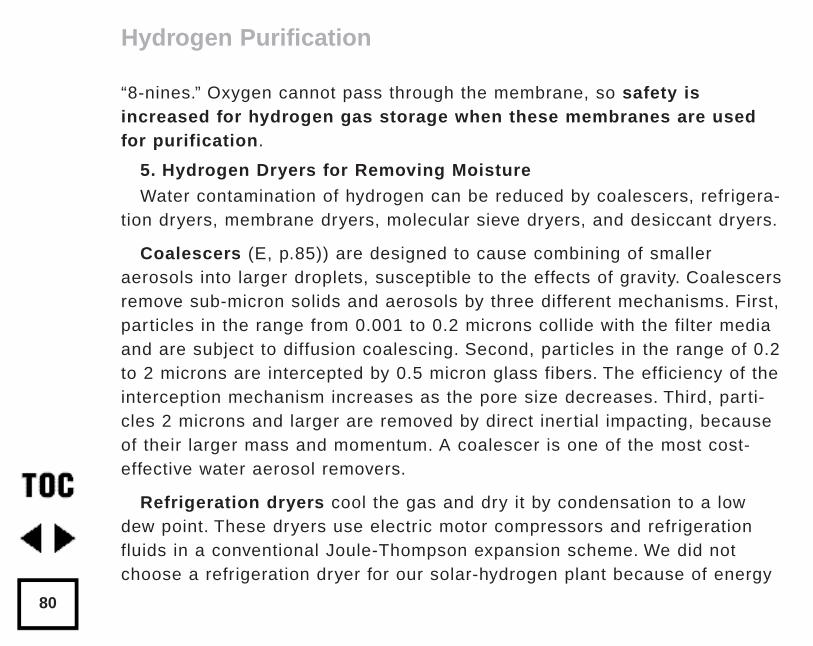
“8-nines.” Oxygen cannot pass through the membrane, so safety isincreased for hydrogen gas storage when these membranes are usedfor purification.
5. Hydrogen Dryers for Removing Moisture
Water contamination of hydrogen can be reduced by coalescers, refrigera-tion dryers, membrane dryers, molecular sieve dryers, and desiccant dryers.
Coalescers (E, p.85)) are designed to cause combining of smalleraerosols into larger droplets, susceptible to the effects of gravity. Coalescersremove sub-micron solids and aerosols by three different mechanisms. First,particles in the range from 0.001 to 0.2 microns collide with the filter mediaand are subject to diffusion coalescing. Second, particles in the range of 0.2to 2 microns are intercepted by 0.5 micron glass fibers. The efficiency of theinterception mechanism increases as the pore size decreases. Third, parti-cles 2 microns and larger are removed by direct inertial impacting, becauseof their larger mass and momentum. A coalescer is one of the most cost-effective water aerosol removers.
Refrigeration dryers cool the gas and dry it by condensation to a lowdew point. These dryers use electric motor compressors and refrigerationfluids in a conventional Joule-Thompson expansion scheme. We did notchoose a refrigeration dryer for our solar-hydrogen plant because of energy
Hydrogen Purification
80
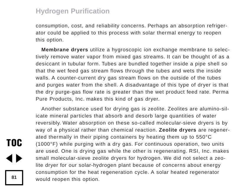
consumption, cost, and reliability concerns. Perhaps an absorption refriger-ator could be applied to this process with solar thermal energy to reopenthis option.
Membrane dryers utilize a hygroscopic ion exchange membrane to selec-tively remove water vapor from mixed gas streams. It can be thought of as adesiccant in tubular form. Tubes are bundled together inside a pipe shell sothat the wet feed gas stream flows through the tubes and wets the insidewalls. A counter-current dry gas stream flows on the outside of the tubesand purges water from the shell. A disadvantage of this type of dryer is thatthe dry purge-gas flow rate is greater than the wet product feed rate. PermaPure Products, Inc. makes this kind of gas dryer.
Another substance used for drying gas is zeolite. Zeolites are alumino-sil-icate mineral particles that absorb and desorb large quantities of waterreversibly. Water absorption on these so-called molecular-sieve dryers is byway of a physical rather than chemical reaction. Zeolite dryers are regener-ated thermally in their piping containers by heating them up to 550°C(1000°F) while purging with a dry gas. For continuous operation, two unitsare used. One is drying gas while the other is regenerating. RSI, Inc. makessmall molecular-sieve zeolite dryers for hydrogen. We did not select a zeo-lite dryer for our solar-hydrogen plant because of concerns about energyconsumption for the heat regeneration cycle. A solar heated regeneratorwould reopen this option.
Hydrogen Purification
81
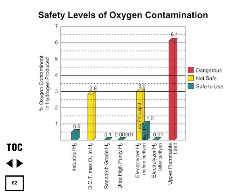
82
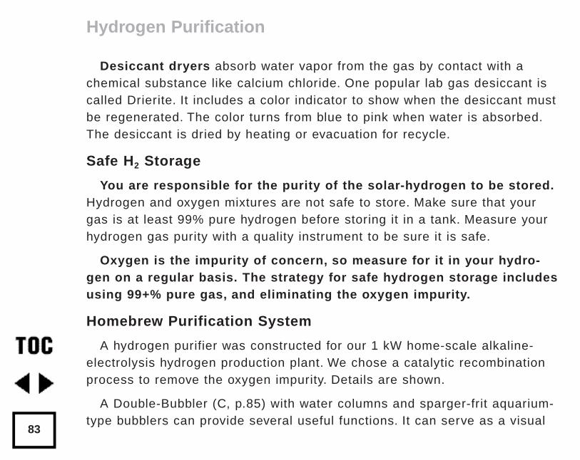
Desiccant dryers absorb water vapor from the gas by contact with achemical substance like calcium chloride. One popular lab gas desiccant iscalled Drierite. It includes a color indicator to show when the desiccant mustbe regenerated. The color turns from blue to pink when water is absorbed.The desiccant is dried by heating or evacuation for recycle.
Safe H2 Storage
You are responsible for the purity of the solar-hydrogen to be stored.Hydrogen and oxygen mixtures are not safe to store. Make sure that yourgas is at least 99% pure hydrogen before storing it in a tank. Measure yourhydrogen gas purity with a quality instrument to be sure it is safe.
Oxygen is the impurity of concern, so measure for it in your hydro-gen on a regular basis. The strategy for safe hydrogen storage includesusing 99+% pure gas, and eliminating the oxygen impurity.
Homebrew Purification System
A hydrogen purifier was constructed for our 1 kW home-scale alkaline-electrolysis hydrogen production plant. We chose a catalytic recombinationprocess to remove the oxygen impurity. Details are shown.
A Double-Bubbler (C, p.85) with water columns and sparger-frit aquarium-type bubblers can provide several useful functions. It can serve as a visual
Hydrogen Purification
83
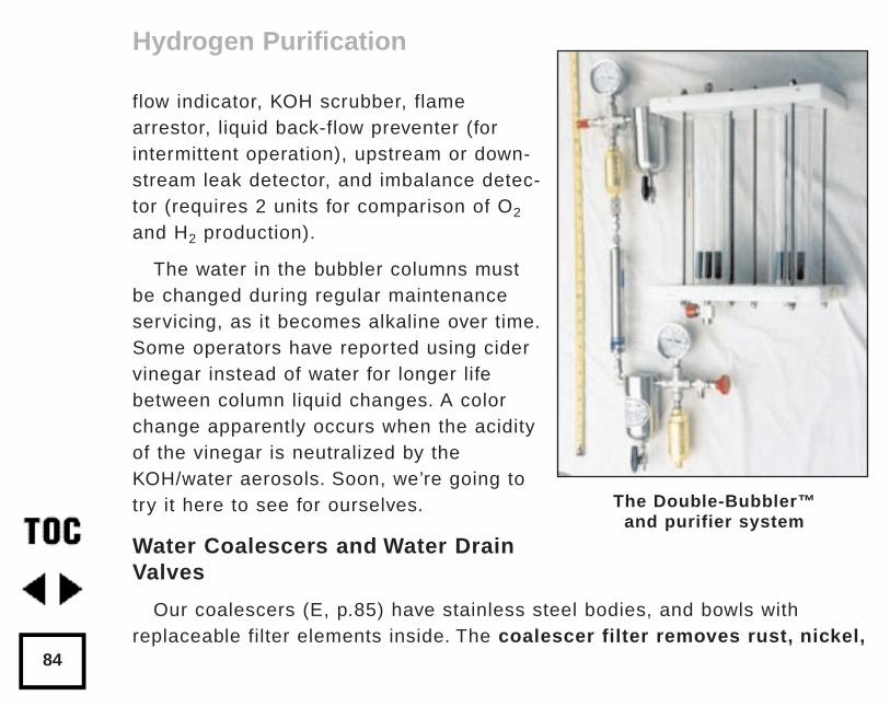
flow indicator, KOH scrubber, flamearrestor, liquid back-flow preventer (forintermittent operation), upstream or down-stream leak detector, and imbalance detec-tor (requires 2 units for comparison of O2
and H2 production).
The water in the bubbler columns mustbe changed during regular maintenanceservicing, as it becomes alkaline over time.Some operators have reported using cidervinegar instead of water for longer lifebetween column liquid changes. A colorchange apparently occurs when the acidityof the vinegar is neutralized by theKOH/water aerosols. Soon, we’re going totry it here to see for ourselves.
Water Coalescers and Water DrainValves
Our coalescers (E, p.85) have stainless steel bodies, and bowls withreplaceable filter elements inside. The coalescer filter removes rust, nickel,
Hydrogen Purification
84
The Double-Bubbler™and purifier system
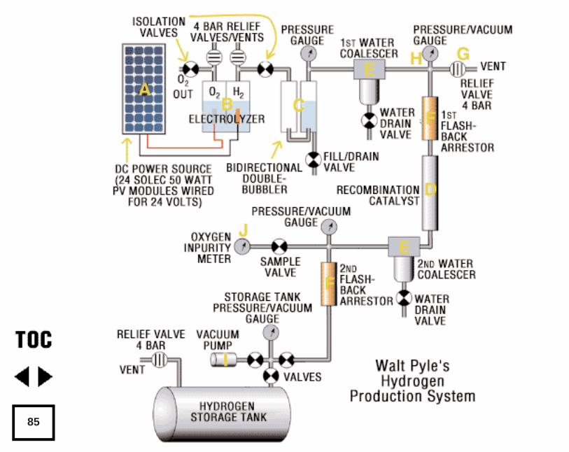
85
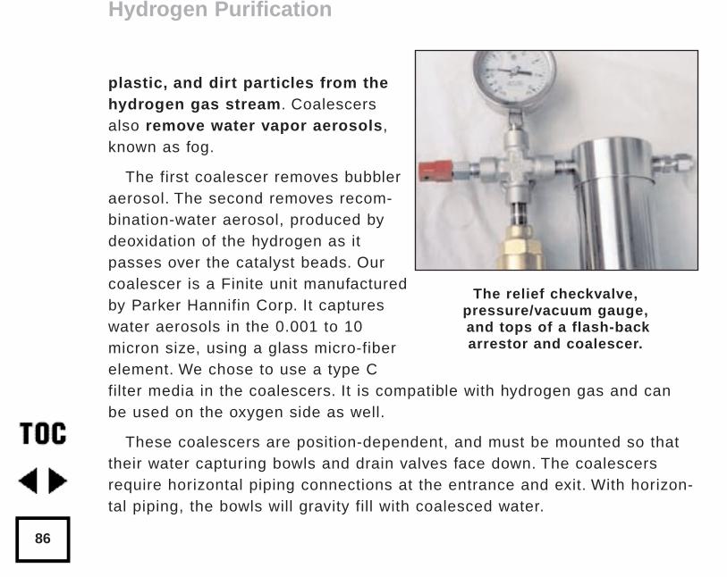
plastic, and dirt particles from thehydrogen gas stream. Coalescersalso remove water vapor aerosols,known as fog.
The first coalescer removes bubbleraerosol. The second removes recom-bination-water aerosol, produced bydeoxidation of the hydrogen as itpasses over the catalyst beads. Ourcoalescer is a Finite unit manufacturedby Parker Hannifin Corp. It captureswater aerosols in the 0.001 to 10micron size, using a glass micro-fiberelement. We chose to use a type Cfilter media in the coalescers. It is compatible with hydrogen gas and canbe used on the oxygen side as well.
These coalescers are position-dependent, and must be mounted so thattheir water capturing bowls and drain valves face down. The coalescersrequire horizontal piping connections at the entrance and exit. With horizon-tal piping, the bowls will gravity fill with coalesced water.
Hydrogen Purification
86
The relief checkvalve,pressure/vacuum gauge,and tops of a flash-backarrestor and coalescer.
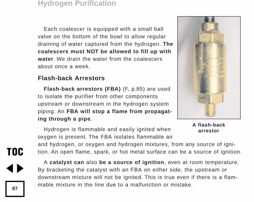
Each coalescer is equipped with a small ballvalve on the bottom of the bowl to allow regulardraining of water captured from the hydrogen. Thecoalescers must NOT be allowed to fill up withwater. We drain the water from the coalescersabout once a week.
Flash-back Arrestors
Flash-back arrestors (FBA) (F, p.85) are usedto isolate the purifier from other componentsupstream or downstream in the hydrogen systempiping. An FBA will stop a flame from propagat-ing through a pipe.
Hydrogen is flammable and easily ignited whenoxygen is present. The FBA isolates flammable airand hydrogen, or oxygen and hydrogen mixtures, from any source of igni-tion. An open flame, spark, or hot metal surface can be a source of ignition.
A catalyst can also be a source of ignition, even at room temperature.By bracketing the catalyst with an FBA on either side, the upstream ordownstream mixture will not be ignited. This is true even if there is a flam-mable mixture in the line due to a malfunction or mistake.
Hydrogen Purification
87
A flash-backarrestor
FBAs are made with a plug of fine silica sand restrained by screens in awide section of piping. The sand quenches any flame-front and stops com-bustion. We prefer the FBAs that have an integral check valve to preventbackflow. Western Enterprises, Inc. makes an FBA appropriate for hydrogenand acetylene gas service.
Check Valve Pressure Relief
A check valve (G, p.85) for pressure relief is set to 4 bar (58 psig) to pre-vent over-pressuring the system by error. If this pressure is exceeded, therelief check valve “cracks” and hydrogen gas is released out of the vent line.When the pressure is reduced to normal operating value (0.5 to 3.5 bargauge), the valve closes once again. Relief valves are subject to drift overtime, so check to be sure that the set pressure and the actual pressureare the same. This should be done at regular maintenance shutdowns.
Compound Pressure Gauges
We use pressure gauges (H, p.85) with all stainless parts to prevent corro-sion failure. They are compound gauges measuring both vacuum and pres-sure. We use the vacuum gauge function to evacuate the system after main-tenance, or before startup of the hydrogen plant. The pressure gauge moni-tors operation of the plant when making hydrogen gas.
Hydrogen Purification
88
De-oxo Catalytic Recombiner
Our catalyst (D) is packed in a stainless steel tube by the supplier and per-forms the key purification function: removing oxygen from the hydrogen gasstream. The catalyst tube must be placed so that the flow enters through thetop and exits at the bottom. This will prevent lofting the particles in the catalystbed and fluidizing them. Keeping the catalyst pipe vertically oriented helps tokeep the flow uniform. Thus, the water formed during de-oxo purificationflows towards the bottom in the same direction as the hydrogen gas. It can beremoved from the purified hydrogen by the second coalescer before it reachesthe second FBA.
Connecting the Purifier to the Electrolyzer
The hydrogen duct coming from the electrolyzer is first connected to the gasinlet port of the Double-Bubbler for KOH/water scrubbing. The scrubbed hydro-gen gas is then fed to the purifier for oxygen removal. We used 1/ 4” stainlesstubing with Swagelok fittings to connect the electrolyzer, bubbler, and purifier.
Purging the Purifier
Before starting the hydrogen plant, flush any possible flammable gas mixture out of the piping with an inert purge gas such as nitrogen or carbon dioxide.
Hydrogen Purification
89
An alternate method to remove flammable gas mixtures from the pipingand other components is to use a mechanical vacuum pump (see p.85). Itmust be capable of producing a vacuum of at least 20 mbar (approximately20 Torr). A vacuum cleaner will not work for this. A two-stage laboratoryvane-type vacuum pump with a thermocouple pressure gauge will work well.
Compound pressure gauges are very useful, because you can see whenthe vacuum has reached less than 20 millibar (>29 inches Hg vacuum). It isalso easy to check if the piping holds vacuum after the pump is removed.Vacuum measurement units have become more standardized in recentyears. Unfortunately, many gauges are still on the market that register vacu-um in inches or millimeters of Hg (mercury) below atmospheric pressure.This can be confusing to the uninitiated.
Start-up of Electrolyzer and Purifier
Once the purifier is ready, we start the electrolyzer by closing the mainelectrical breaker to the DC power supply. Then, we wait twenty minutes orso for the float valves on the Hydrogen Wind electrolyzer to fill. Next, weclose the vent valve on the electrolyzer. Pressure in the electrolyzer willbegin to rise. Slowly, we open the isolation valve between the electrolyzerand the Double-Bubbler. Gas will enter the purged purifier. After the hydro-gen flow through the Double-Bubbler has stabilized, we open the isolationvalve all the way, and leave the valve open.
Hydrogen Purification
90
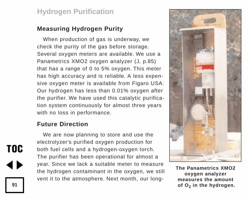
Measuring Hydrogen Purity
When production of gas is underway, wecheck the purity of the gas before storage.Several oxygen meters are available. We use aPanametrics XMO2 oxygen analyzer (J, p.85)that has a range of 0 to 5% oxygen. This meterhas high accuracy and is reliable. A less expen-sive oxygen meter is available from Figaro USA.Our hydrogen has less than 0.01% oxygen afterthe purifier. We have used this catalytic purifica-tion system continuously for almost three yearswith no loss in performance.
Future Direction
We are now planning to store and use theelectrolyzer’s purified oxygen production forboth fuel cells and a hydrogen-oxygen torch.The purifier has been operational for almost ayear. Since we lack a suitable meter to measurethe hydrogen contaminant in the oxygen, we stillvent it to the atmosphere. Next month, our long-
Hydrogen Purification
91
The Panametrics XMO2oxygen analyzer
measures the amountof O2 in the hydrogen.
awaited hydrogen meter from DCH, Inc. is due to be delivered. The DCH meteris designed to measure from the ppm level to 100% hydrogen. In a future arti-cle, we will share our experience with oxygen purification and storage.
Acknowledgements
The author gratefully acknowledges the assistance of the following individu-als in fabricating, testing, and documenting this system: Mark Hayes, H-IonSolar, Inc.; Reynaldo Cortez, Shadowbox Construction Co.; Don Mackinder, H-Ion Solar, Inc.; Larry T. Pyle, Pyle Manufacturing Consulting; and Pat andAngello Scipi, A & K Machine.
Access:
Author: Walt Pyle, H-Ion Solar, 6095 Monterey Ave., Richmond, CA94805 • 510-237-7877 Fax: 510-232-5251 • [email protected] Web:www.hionsolar.com
Safety Information: Air Products and Chemicals, Inc., “Safetygram 4” onGaseous Hydrogen • 610-481-4911
Alkaline Electrolyzer: Hydrogen Wind Inc., RR2 Box 262, Lineville, IA641-876-5665
Catalyst Suppliers: Resource Systems Inc., Six Merry Lane, EastHanover, NJ 07936 • 973-884-0650 • Fax: 973-515-3166 GPT, Inc. • 732-446-2400 • Fax: 732-446-2402
Hydrogen Purification
92
Access (continued)
Coalescer:A.F. Equipment Co., Inc., 1273 Forgewood Ave., Sunnyvale, CA 94089-2216 • 408-734-2525Parker Hannifin Corp., 17325 Euclid Ave., Cleveland, OH 44112 • 800-506-4261 • 216-531-3000
Complete Purifier System (Model PT-4) and Double-Bubbler (ModelDB-3): H-Ion Solar, Inc., see Walt Pyle above.
Flash-back Arrestor (Western Enterprises Model FCV-3A): AtlasWelding Co., 1224 6th Street, Berkeley, CA 94710 510-524-5117 • Fax:510-524-9098
Hydrogen Membrane Dryer: Perma Pure Products, Inc. • 732-244-8140
Palladium-alloy Membrane:Johnson Matthey, Inc. • 44-1763-253306 (Great Britain) 610-971-3100(USA)Teledyne-Wah Chang, Inc. • 541-967-6904
Polymeric Membrane: Permea, Inc. • 800-635-8842
Pressure Gauge: Fluid Gauge Co., P.O. Box 881833 San Francisco, CA94188 • 415-285-0648
Stainless Pipe Fittings: Oakland Valve and Fitting Co., 2441 Sprig Ct. -Unit A, Concord, CA 94520• 510-676-4100 Fax: 510-798-9833
Hydrogen Purification
93
by Walt PyleOriginally published in Home Power #59 • June / July 1997 ©1997 Walt Pyle
Hydrogen storage is needed for homes, businesses, and vehicles, to real-ize the dream of the Solar Hydrogen Age. Since hydrogen gas is useful as afuel for cooking, heating, electricity production, and vehicle propulsion, weneed a way to store the solar hydrogen made during the day for use atnight, and seasonally as well.
For more insight on how this wonderful fuel can be used and producedsee the chapters about cooking with hydrogen (p.118 and 129), space heat-ing with hydrogen (p.143), making electricity with hydrogen (p.169), andhydrogen production from PV and wind electricity (p.20, 32, 38, 44).
Most home energy use occurs in the evening when there is no solarhydrogen production occurring from a home hydrogen plant. Over-nighthydrogen storage can solve this problem. Summer-time solar hydrogen pro-duction can meet or exceed home consumption requirements. Winter-timehydrogen demand (for heating) is maximum at the time when solar hydrogenproduction is at a minimum. Seasonal home storage can correct this out-of-phase relationship.
Hydrogen Storage
94
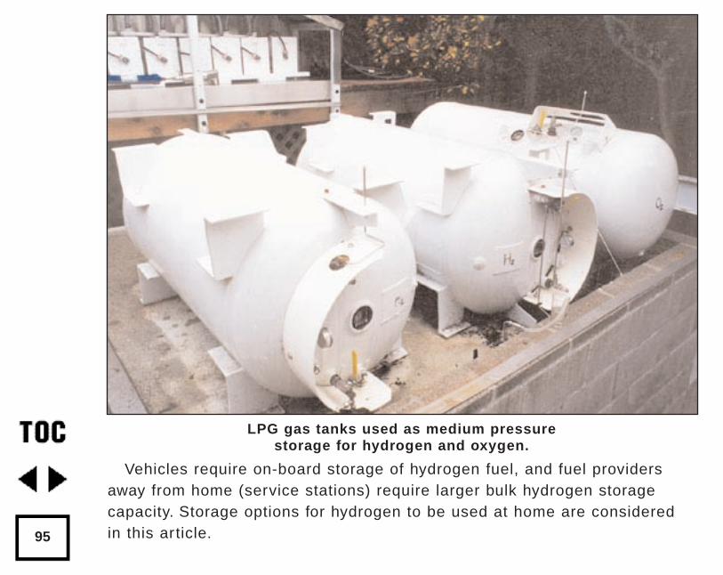
Vehicles require on-board storage of hydrogen fuel, and fuel providersaway from home (service stations) require larger bulk hydrogen storagecapacity. Storage options for hydrogen to be used at home are consideredin this article.95
LPG gas tanks used as medium pressure storage for hydrogen and oxygen.
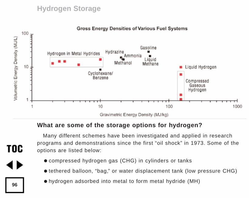
What are some of the storage options for hydrogen?
Many different schemes have been investigated and applied in researchprograms and demonstrations since the first “oil shock” in 1973. Some of theoptions are listed below:
compressed hydrogen gas (CHG) in cylinders or tanks
tethered balloon, “bag,” or water displacement tank (low pressure CHG)
hydrogen adsorbed into metal to form metal hydride (MH)
Hydrogen Storage
96
liquid hydrogen (LH2 ) in cryogenic tank
adsorption on high-surface-area carbon powder in tank
encapsulation in glass micro-spheres (experimental)
adsorption on carbon “nano-tubes” (experimental)
in water (H2O) (not a “fuel”)
in ammonia (NH3)
in liquid hydro-carbons: gasoline, diesel fuel, alcohol,
liquid natural gas (LNG), propane or butane (LPG), etc.
in gaseous hydrocarbons: compressed natural gas (CNG), bio-gas, etc.
The first three hydrogen storage options above, CHG, MH, and LH2, arethe “stateof-the-art” methods most frequently applied in vehicular and station-ary applications. The energy density of different hydrogen storage options areshown below, and compared to that of gasoline.
The last two hydrogen storage options, using liquid and gaseous hydro-car-bons, are the fossil-fuels that dominate our global fuel production and con-sumption systems today. For example, a large amount of hydrogen is addedto petroleum feedstock to make gasoline. These liquid hydrocarbon fuels arewidely used in transportation because of their extremely high energy density.
Hydrogen Storage
97
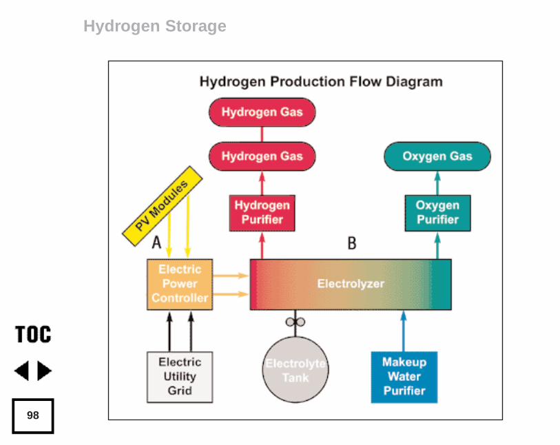
Hydrogen Storage
98
In this article we are focusing on the CHG and MH storage options, sincethey are the easiest to implement for home power applications at this time.LH2 production requires a large energy expenditure for refrigeration to lique-fy gaseous hydrogen. LH2 is primarily used for transportation applications,so we choose not to elaborate on this method now. We also “gloss over” theexperimental hydrogen storage options in this article, since their values arestill being proven.
Safety First!
If hydrogen is to be stored, it must first be made safe to store. Hydrogenand air, or hydrogen and oxygen mixtures are not safe to store if the O2 con-tamination is significant. Hydrogen has much wider flammable and explosivelimits compared to other fuels, especially in hydrogen-rich mixtures with airor oxygen. Hydrogen flammable limits are shown on page 16 and comparedto some common fossil fuels.
Hydrogen should never be stored unless it is well below the lower flamma-ble limit (LFL). Normally, industry standards for storage safety call for wellbelow 0.25 LFL, (or less than 1% oxygen in the hydrogen.) To meet thisstandard, some way of accurately measuring the oxygen contaminant in theproduced solar hydrogen must be available. Some hydrogen sensors are list-ed in the access section at the end of this article
Hydrogen Storage
99
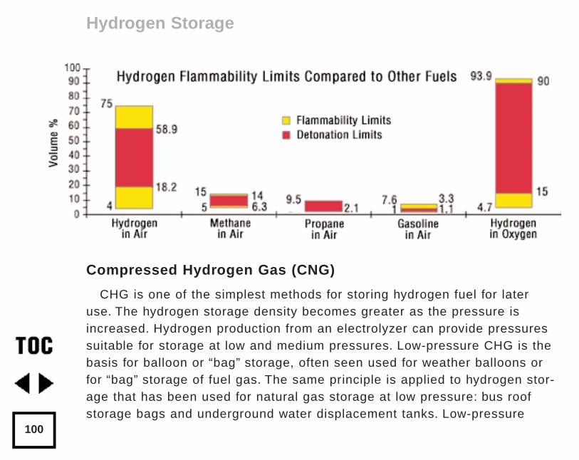
Compressed Hydrogen Gas (CNG)
CHG is one of the simplest methods for storing hydrogen fuel for lateruse. The hydrogen storage density becomes greater as the pressure isincreased. Hydrogen production from an electrolyzer can provide pressuressuitable for storage at low and medium pressures. Low-pressure CHG is thebasis for balloon or “bag” storage, often seen used for weather balloons orfor “bag” storage of fuel gas. The same principle is applied to hydrogen stor-age that has been used for natural gas storage at low pressure: bus roofstorage bags and underground water displacement tanks. Low-pressure
Hydrogen Storage
100
tanks are widely used in China and India for storage of bio-gas fuels.Pressures in these low-pressure CHG containers are only slightly aboveatmospheric pressure, and they are characterized by very large volume andlow container weight.
Medium Pressure CHG Storage
This type of storage has been done using tanks originally designed for airor propane (LPG) service. Typically these tanks are rated for about 17 bar(250 psig) maximum pressure in the intended service, and de-rated to 4.1 to8.6 bar (60 to 125 psig) maximum when used for storing hydrogen.
The tank alloy should be low-carbon steel or another material resistant to,or unaffected by, hydrogen embrittlement (weakening) of the tank alloy.High-carbon steel tanks are not appropriate for storing hydrogen under pres-sure. To avoid hydrogen tank embrittlement, avoid steels that are: a) cold-rolled or cold-forged, or b) have weld hard spots in excess of about VickersHardness Number 260.
Non-metal tanks such as composite-fiber tanks avoid hydrogen embrittle-ment concerns and de-rating.
Medium-pressure CHG storage tanks are characterized as having smallersize and greater weight, for a given storage capacity, relative to low-pres-sure CHG tanks.
Hydrogen Storage
101
Safety First!
Tanks intended for use with significant hydrogen pressure should behydrostatically tested to at least twice the intended operating pressure,and equipped with a suitable pressure release device. All storage tanks forhydrogen should be installed outdoors, never inside buildings or enclosedspaces. A flash-back arrestor should be used on each of the tank’s inputand output lines to prevent flame propagation, in the event a flammablemixture forms due to any mistake or system break-down.
High Pressure CHG Storage
This is the densest compressed hydrogen gas storage option. A com-pressor is normally used to increase the hydrogen pressure. Typical stor-age pressures of 140 to 400 bar (2000 to 5800 psig) maximum are used inwelding cylinders, tube trailers, and composite-fiber cylinders. It is possi-ble to eliminate the hydrogen compressor by operating the hydrogen pro-duction process at the desired high pressure, for example, by using ahigh-pressure electrolyzer.
Most merchant CHG that is used for welding or other industrial purpos-es is handled in steel cylinders that contain 5.7 to 8.5 m 3 (200 to 300scf). These small cylinders are about 1.4 m high and 0.2 m diameter (56inches high and 8 inches diameter). When we have visited hydrogen
Hydrogen Storage
102
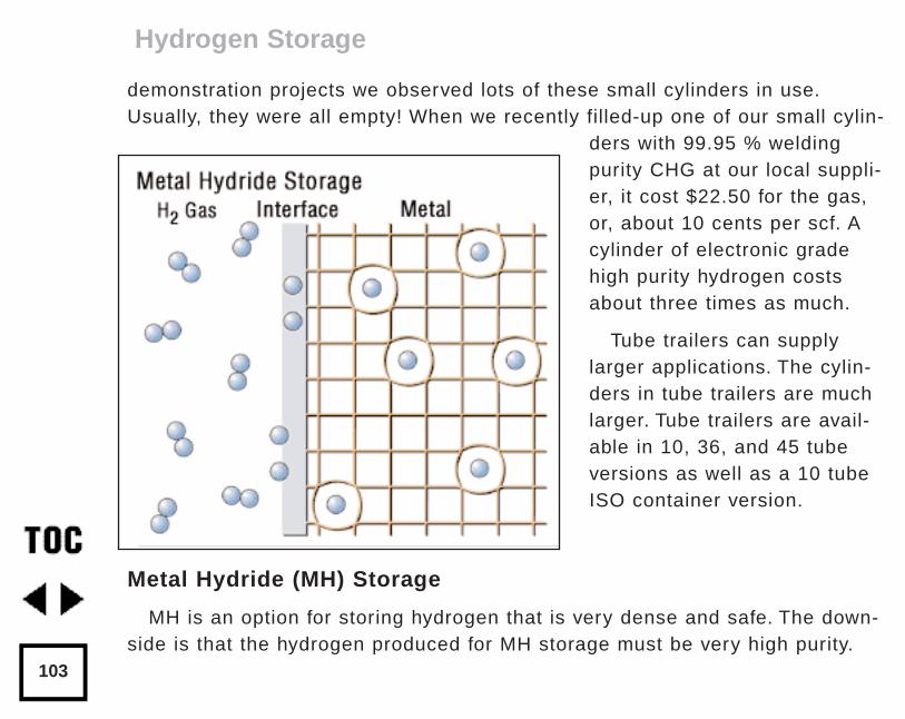
demonstration projects we observed lots of these small cylinders in use.Usually, they were all empty! When we recently filled-up one of our small cylin-
ders with 99.95 % weldingpurity CHG at our local suppli-er, it cost $22.50 for the gas,or, about 10 cents per scf. Acylinder of electronic gradehigh purity hydrogen costsabout three times as much.
Tube trailers can supplylarger applications. The cylin-ders in tube trailers are muchlarger. Tube trailers are avail-able in 10, 36, and 45 tubeversions as well as a 10 tubeISO container version.
Metal Hydride (MH) Storage
MH is an option for storing hydrogen that is very dense and safe. The down-side is that the hydrogen produced for MH storage must be very high purity.
Hydrogen Storage
103
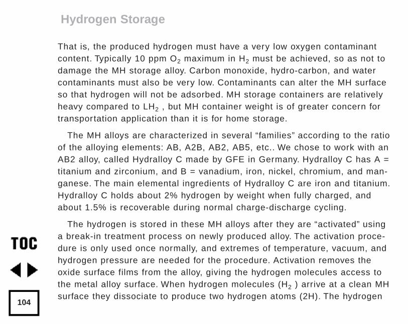
That is, the produced hydrogen must have a very low oxygen contaminantcontent. Typically 10 ppm O2 maximum in H2 must be achieved, so as not todamage the MH storage alloy. Carbon monoxide, hydro-carbon, and watercontaminants must also be very low. Contaminants can alter the MH surfaceso that hydrogen will not be adsorbed. MH storage containers are relativelyheavy compared to LH2 , but MH container weight is of greater concern fortransportation application than it is for home storage.
The MH alloys are characterized in several “families” according to the ratioof the alloying elements: AB, A2B, AB2, AB5, etc.. We chose to work with anAB2 alloy, called Hydralloy C made by GFE in Germany. Hydralloy C has A =titanium and zirconium, and B = vanadium, iron, nickel, chromium, and man-ganese. The main elemental ingredients of Hydralloy C are iron and titanium.Hydralloy C holds about 2% hydrogen by weight when fully charged, andabout 1.5% is recoverable during normal charge-discharge cycling.
The hydrogen is stored in these MH alloys after they are “activated” usinga break-in treatment process on newly produced alloy. The activation proce-dure is only used once normally, and extremes of temperature, vacuum, andhydrogen pressure are needed for the procedure. Activation removes theoxide surface films from the alloy, giving the hydrogen molecules access tothe metal alloy surface. When hydrogen molecules (H2 ) arrive at a clean MHsurface they dissociate to produce two hydrogen atoms (2H). The hydrogen
Hydrogen Storage
104
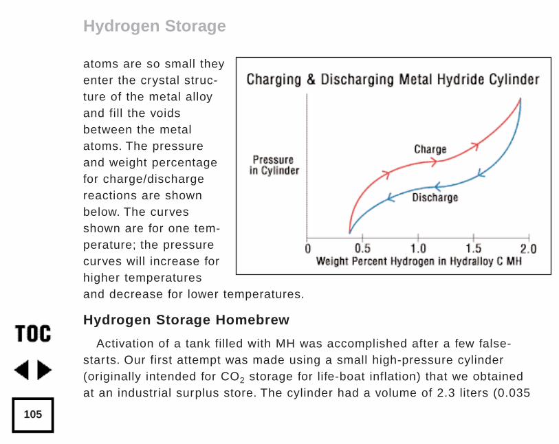
atoms are so small theyenter the crystal struc-ture of the metal alloyand fill the voidsbetween the metalatoms. The pressureand weight percentagefor charge/dischargereactions are shownbelow. The curvesshown are for one tem-perature; the pressurecurves will increase forhigher temperaturesand decrease for lower temperatures.
Hydrogen Storage Homebrew
Activation of a tank filled with MH was accomplished after a few false-starts. Our first attempt was made using a small high-pressure cylinder(originally intended for CO2 storage for life-boat inflation) that we obtainedat an industrial surplus store. The cylinder had a volume of 2.3 liters (0.035
Hydrogen Storage
105
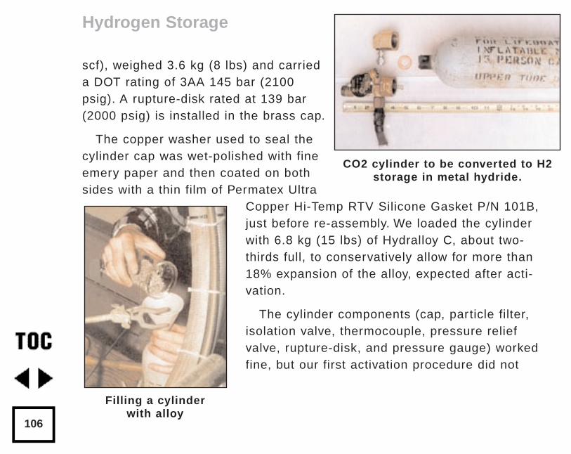
scf), weighed 3.6 kg (8 lbs) and carrieda DOT rating of 3AA 145 bar (2100psig). A rupture-disk rated at 139 bar(2000 psig) is installed in the brass cap.
The copper washer used to seal thecylinder cap was wet-polished with fineemery paper and then coated on bothsides with a thin film of Permatex Ultra
Copper Hi-Temp RTV Silicone Gasket P/N 101B,just before re-assembly. We loaded the cylinderwith 6.8 kg (15 lbs) of Hydralloy C, about two-thirds full, to conservatively allow for more than18% expansion of the alloy, expected after acti-vation.
The cylinder components (cap, particle filter,isolation valve, thermocouple, pressure reliefvalve, rupture-disk, and pressure gauge) workedfine, but our first activation procedure did not
Hydrogen Storage
106
CO2 cylinder to be converted to H2storage in metal hydride.
Filling a cylinderwith alloy
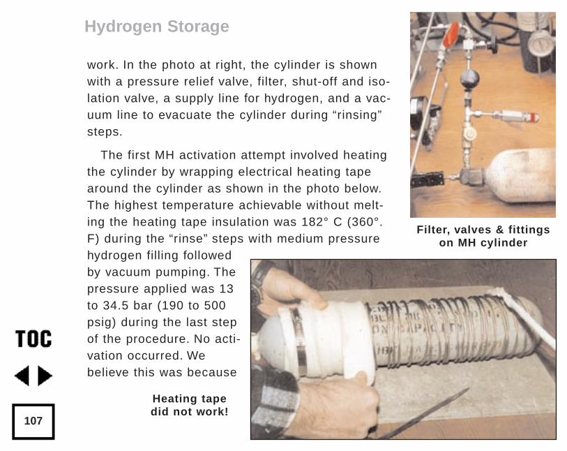
work. In the photo at right, the cylinder is shownwith a pressure relief valve, filter, shut-off and iso-lation valve, a supply line for hydrogen, and a vac-uum line to evacuate the cylinder during “rinsing”steps.
The first MH activation attempt involved heatingthe cylinder by wrapping electrical heating tapearound the cylinder as shown in the photo below.The highest temperature achievable without melt-ing the heating tape insulation was 182° C (360°.F) during the “rinse” steps with medium pressurehydrogen filling followedby vacuum pumping. Thepressure applied was 13to 34.5 bar (190 to 500psig) during the last stepof the procedure. No acti-vation occurred. Webelieve this was because
Hydrogen Storage
107
Filter, valves & fittingson MH cylinder
Heating tape did not work!
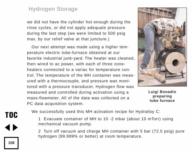
we did not have the cylinder hot enough during therinse cycles, or did not apply adequate pressureduring the last step (we were limited to 500 psigmax. by our relief valve at that juncture.)
Our next attempt was made using a higher tem-perature electric tube-furnace obtained at ourfavorite industrial junk-yard. The heater was cleaned,then wired to ac power, with each of three zone-heaters connected to a variac for temperature con-trol. The temperature of the MH container was meas-ured with a thermocouple, and pressure was moni-tored with a pressure transducer. Hydrogen flow wasmeasured and controlled during activation using amass-flowmeter. All of the data was collected on aPC data acquisition system.
We successfully used this MH activation recipe for Hydralloy C:
1 Evacuate container of MH to 10 -2 mbar (about 10 mTorr) usingmechanical vacuum pump.
2 Turn off vacuum and charge MH container with 5 bar (72.5 psig) purehydrogen (99.999% or better) at room temperature.
Hydrogen Storage
108
Luigi Bonadio preparing
tube furnace
3 Make a leak test with gas leak detector, if system is tight and thereare no leaks, proceed.
4 Turn off hydrogen supply and vacuum out MH container to completefirst “rinse” cycle.
5 Repeat hydrogen charge to 5 bar.
6 Remove H2 by vacuum pump to 10 -2 mbar to complete the second“rinse.”
7 Heat container in tube-furnace to 375°C (707°F) while continuing toevacuate to remove hydrogen and contaminants like water vapor(about 4 hours).
8 Turn off vacuum and charge MH container with 5 bar pure hydrogenat 375°C (hold for 8 hours).\
9 Evacuate to complete third “rinse.”
10 Repeat 5 bar hydrogen charge at 375°C (hold about 4 hours).
11 Evacuate to complete fourth “rinse.”
12 Under 5 bar hydrogen pressure cool down the MH container toroom temperature.
13 Leak test the cylinder to verify that the sealant is still good after thehigh temperature rinse steps. If no leaks are present, continue.
Hydrogen Storage
109
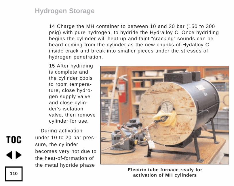
14 Charge the MH container to between 10 and 20 bar (150 to 300psig) with pure hydrogen, to hydride the Hydralloy C. Once hydridingbegins the cylinder will heat up and faint “cracking” sounds can beheard coming from the cylinder as the new chunks of Hydalloy Cinside crack and break into smaller pieces under the stresses ofhydrogen penetration.
15 After hydridingis complete andthe cylinder coolsto room tempera-ture, close hydro-gen supply valveand close cylin-der’s isolationvalve, then removecylinder for use.
During activationunder 10 to 20 bar pres-sure, the cylinderbecomes very hot due tothe heat-of-formation ofthe metal hydride phase
Hydrogen Storage
110Electric tube furnace ready for
activation of MH cylinders
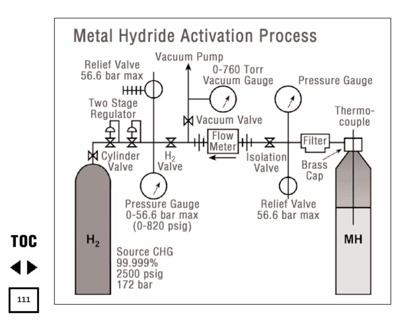
111
(2M + H2 = 2MH + heat). Our cylinder container reached a temperature ofover 70°.C, so we turned on an air fan to cool it. After about two hours thehydriding reaction was complete and the container gradually cooled down toroom temperature. Each time the cylinder is filled with hydrogen, the cylinderreleases heat. After activation, the cylinder can be re-charged at much lowerpressure. For Hydralloy C we were able to recharge the container, after acti-vation, with hydrogen at only 8 bar (100 psig) pressure, without any externalheating, cooling, or vacuuming. Using a higher hydrogen pressure duringcharging resulted in a faster fill and greater heat-release rate. Note; onebatch of MH that we made required 50 bar (725 psig) pressure to hydride thefirst time, probably because of thicker surface oxide films.
Removal of Hydrogen from Hydralloy C
This was done by opening the MH container’s valve and feeding gas to ahydrogen cooking burner. As the gas was removed from the MH container, thecontainer became cold enough to form ice on the outer surface (from themoisture in the room air freezing). At lower hydrogen removal rates, ice didnot form because the container gained heat from the ambient air fast enoughto keep up with the reverse reaction (2MH + heat = 2M + H2 ). MH has beenused in refrigeration systems because of this unique property and because of
Hydrogen Storage
112
hydrogen’s “ozone friendly” nature compared to other refrigerants like CFCs.A discussion of MH refrigeration is beyond the scope of this article.
Our cylinder container held about 6.8 kg of Hydralloy C so we expected toobtain about 1.5% weight of hydrogen, or about 100 grams of hydrogen ondischarge. This might not seem like very much hydrogen, but since hydrogenis very light, the volume of 100 grams hydrogen at atmospheric pressure islarge, about 1.1 m 3 (39 scf). Not bad for a cylinder with a volume of 0.0023m3 (0.035 scf). By comparison, we would need to boost the pressure in thesame cylinder with CHG to 1.1/.0023 = 478 bar to get as much hydrogeninto it as with 14 bar in a MH cylinder! Since the cylinder is rated at only145 bar, this is impossible.
On the first hydrogen fill, the storage volume may not be as large as thatobtained after several charge/discharge cycles. The MH breaks down intosmaller and smaller particles during the first few cycles and the storage vol-ume increases. We obtained about 0.64 m 3 (640 liters or 23 scf) of hydro-gen from the cylinder after the first filling following activation.
The pressure inside a filled Hydralloy C MH cylinder varies from about 5.5to 8.3 bar (80 to 120 psig) depending on ambient temperature 5 to 27 deg.C (40 to 80 deg. F). When the isolation valve is opened to feed gas to acooking burner, the pressure drops. If the valve is then closed, after a timethe pressure will recover, as the hydrogen leaves the alloy and fills thespace in the cylinder. When the cylinder is emptied (weight % H 2 less than
Hydrogen Storage
113
about 0.5) the pressure will not recover after valve shutoff, and it is time torecharge the cylinder with hydrogen.
Future Direction
As we go to press, a second MH container is being activated withHydralloy C, a third cylinder of Hydralloy F 50/9 (AB 4.8 alloy) is being acti-vated, and a cluster of small MH cylinders is being installed inside a largestainless steel container (formerly used as a swimming pool filter case).Water and anti-freeze solution will be circulated around the MH cylinders, toremove heat during hydrogen charging, and to supply heat during hydrogendischarging. A base support has been added so the pool-filter-case with it’sMH cylinders can be installed at home or in a small pick-up truck. We’ll tellyou about it later on.
Acknowledgments:
Mike Williams, Shieldalloy Metallurgical Corporation for many enlight-ening discussions on MH and Hydralloy
C Luigi Bonadio, University of Melbourne (Australia) for assistance inactivation of Hydralloy C and preparation of experimental hardwareand computer data acquisition system at H-Ion Solar Company
Michael Gottschall, GFE Mbh for MH engineering applications information
Dr. Meinhard Aits GFE Mbh for MH technical information
Hydrogen Storage
114
Acknowledgments (continued)
Dale McIntyre, Metallurgical Engineer, Aramco, Saudi Arabia for infor-mation about metallurgy of hydrogen handling systems in refineries,sour gas fields, and gas sweetening units
Jim Healy WH6LZ for assembly of laboratory apparatus, experimentaldata collection, and safety checks
David Booth for assistance with the CO2 cylinder conversions
Reynaldo Cortez for some of the photographs
Access:
Author: Walt Pyle WA6DUR, H-Ion Solar Company, 6095 MontereyAvenue Richmond, CA 94805 Tel: (510) 237-7877 FAX: (510) 232-5251e-mail: [email protected]
Metal Hydride Review article:“Hydrogen Metal Systems”, by Gary Sandrock, Y. Yurum, Editor, NATOASI Series E: Applied Sciences - Vol.295, Kluwer AcademicPublishers, Dordrecht, 1995, pp.135-166
Hydralloy C MH-alloy and tank sourcesGFE Mbh, Hofener Strasse 45 D-90431 Nurnberg, Germany Tel: 49(country code) 93(city code) 15 332 FAX: 49-31-49-80 or 49-9315-491
Shieldalloy Metallurgical Corp., 12 West Boulevard Newfield, NewJersey 08344 Tel: (609) 692-4200 FAX: (609) 692-4017
Hydrogen Storage
115
Hydrogen PurifiersResource Systems Inc., East Hanover, New Jersey Tel: (201) 884-0650FAX: (201) 515-3166 RCP-10- 2000-4ss catalytic hydrogen purifier
Johnson-Matthey Corp., Orchard Rd, Hertfordshire, SG8 5HE, EnglandTel: (01763) 25-3000 FAX: (01763) 25-3313 Thin Pd-Ag membrane H2 purifiers
Bend Research Inc. 64550 Research Road, Bend, Oregon, 97701-8599Tel: (503) 382 4100 FAX: (503) 382 2713 Pd membrane purifiers
REB Research, Ferndale, Michigan Tel: (810) 545-0155 FAX: (810) 545-5430 Hydrogen purifiers and Membrane Reactors
GPT Inc., Manalapan, New Jersey Tel: (908) 446-2400 FAX: (908) 446-2402 Hydrogen De-oxo purifier D-50- 1000
Hydrogen and Oxygen Purity SensorsDCH Technology Inc., Sherman Oaks, California Tel:1-{818) 385-0849FAX: (818) 385-0849 e-mail: [email protected] (ppm to 100% hydrogen)Robust Hydrogen Sensor (ppm to 100% hydrogen)
Figaro USA Inc., Wilmette, Illinois Tel: 1-(708) 256-3546 FAX: (708)256-3884 KE50 oxygen sensor (to detect oxygen contamination inhydrogen)
Panametrics inc., Waltham, Massachusetts Tel: (800) 8333-9438 FAX:(617)-894-8582 Thermoparamagnetic Oxygen Transmitter 0–5% O2
Hydrogen Storage
116
Hydrogen flash-back arrestorsWestern Enterprises, West Lake, Ohio. Model FA3-CV flash-back arrestorwith integral check valve (used for acetylene) Tel: (216) 871-2160Hydrogen pressure relief valves, shut-off valves, tubing, gas filters.
Oakland Valve and Fitting Co., Concord, California Tel: (510) 676-4100Includes Swagelock, Whitey, Cajon, Nupro product lines
Hydrostatic Testing of CylindersCompressed Gas Association, 1725 Jefferson Davis Highway, Suite1004, Arlington, Virginia 22202-4102
Articles on storage of hydrogen in carbon “nanotubes”and on carbon powder“Advanced Materials for Hydrogen Storage: Carbon Nanotubules”, T.A.Bekkedahl and M.J. Heben, National Renewable Energy Laboratory,Golden, Colorado
“Hydrogen Storage Systems using Activated Carbon”, J.S. Noh, R.K.Agarwal, J.A. Schwarz, Int.J.Hydrogen Energy, Vol.12, No.10, pp.693-700, 1987.
Hydrogen Storage
117
by David Booth and Walt PyleOriginally published in Home Power #33 February / March 1993©1993 David Booth and Walt Pyle
Converting conventional stove top burners to run on hydrogen is a simpleprocess. Knowing the proper handling procedures of hydrogen will makeyour installation safe and efficient.
Theory Before Practice
Hydrogen burns differently than either propane or natural gas. In particu-lar, hydrogen’s rate of diffusion and flame velocity are roughly ten times orgreater than that of propane or natural gas. Diffusion rate measures howlong it takes a gas introduced in one side of a room to be detected on theother side. Flame speed is how fast a flame travels to burn available fuel-air mixture.
Flashback of the flame into the primary mixture of fuel gas and air mustbe prevented in all burners. This is typically achieved with natural gas andpropane by adjusting the fuel velocity so that it is higher than the normalflame velocity. The flame velocity of hydrogen is too high for this techniqueto be practical. Another flashback control strategy employs burner portswith a minimum quenching diameter which theoretically will not allow the
Cookin’ On Hydrogen:Stove Burner Conversion
118
flame to pass back through the port. In practice, however, it is very difficultto make the holes small enough to quench a hydrogen flame. Fortunately,flashback can be minimized by preventing hydrogen from mixing with airbefore the burner port. Some flashback may still occur creating a loud pop-ping sound but this noise is usually harmless.
Figure 1 (next page) shows the principal parts of a typical range top burn-er used with conventional gaseous fuels. Usually the fuel streams in througha gas orifice with a delivery pressure between 3-15 inches of water column.Primary air is then drawn in with the gas stream through an air-gas mixer.Secondary air openings to mix in more air may or may not be present.Finally, as the mixture exits through the burner ports, combustion occurs, ifa spark ignition source or pilot light is present.
Horse of a Different Color
This burner design will not suffice for hydrogen in an unaltered state.Burners optimized for hydrogen combustion require that undiluted hydrogenbe delivered directly to the burner ports without primary or secondary airmixing. So, if we are trying to work with an existing burner in a typical gasappliance, we will have to find a suitable method to seal off any openingsthat were installed for this purpose. There’s no method that will work in allinstances. The actual openings we are referring to may be an integral part of
Cookin’ On Hydrogen
119
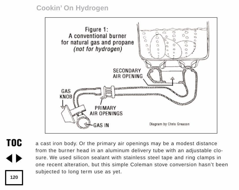
a cast iron body. Or the primary air openings may be a modest distancefrom the burner head in an aluminum delivery tube with an adjustable clo-sure. We used silicon sealant with stainless steel tape and ring clamps inone recent alteration, but this simple Coleman stove conversion hasn’t beensubjected to long term use as yet.
Cookin’ On Hydrogen
120
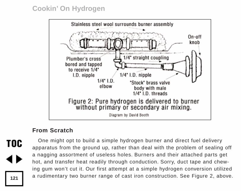
From Scratch
One might opt to build a simple hydrogen burner and direct fuel deliveryapparatus from the ground up, rather than deal with the problem of sealing offa nagging assortment of useless holes. Burners and their attached parts gethot, and transfer heat readily through conduction. Sorry, duct tape and chew-ing gum won’t cut it. Our first attempt at a simple hydrogen conversion utilizeda rudimentary two burner range of cast iron construction. See Figure 2, above.
Cookin’ On Hydrogen
121
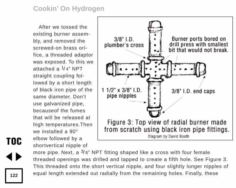
After we tossed theexisting burner assem-bly, and removed thescrewed-on brass ori-fice, a threaded adaptorwas exposed. To this weattached a 1/ 4” NPTstraight coupling fol-lowed by a short lengthof black iron pipe of thesame diameter. Don’tuse galvanized pipe,becauseof the fumesthat will be released athigh temperatures.Thenwe installed a 90°elbow followed by ashortvertical nipple ofmore pipe. Next, a 3/ 8” NPT fitting shaped like a cross with four femalethreaded openings was drilled and tapped to create a fifth hole. See Figure 3.This threaded onto the short vertical nipple, and four slightly longer nipples ofequal length extended out radially from the remaining holes. Finally, these
Cookin’ On Hydrogen
122
terminated in threaded end caps. A drill press is almost essential for drillinga series of very fine holes which lineup along the top of the radial burnerarms, and through the top of the cross. Ideally, these burner ports would-have a 0.057 cm (0.0225”) diameter or less, which is the approximate mini-mum quenching diameter.
The Catalytic Advantage
It has been observed in early experiments that the flame combustion ofhydrogen/air mixtures can lead to unacceptable levels of nitrogen oxide(NOx) pollutant emissions. The primary end product of hydrogen combustionis simply water vapor. However, if the temperature of combustion exceeds athreshold level of about 1315°C (2400°F), a significant amount of oxygenand nitrogen from the air may react and form this unwanted byproduct. Thisalso occurs with natural gas (primarily methane), propane, and other hydro-carbon fuel combustion.
Fortunately, you can use a catalyst to lower the combustion temperature,thus preventing the formation of nitrogen oxides. The catalytic material isnot used up or altered in any fashion in the process.
There are two catalytic conversion techniques which succeed in produc-ing negligible levels of NOx emissions.The first approach is based onBillings and his associates’ work with flame assisted catalytic burners. Their
Cookin’ On Hydrogen
123
conversions utilized the catalytic properties of stainless steel at elevatedtemperatures. Later, in another article, we’ll describe the conversion of acatalytic space heater which optimizes “flameless” combustion with a small-amount of platinum.
Flame Assisted Catalysis
The technique developed by the Billing’s research team to reduce NOx for-mation relies on controlling two interacting phenomena. First, as has alreadybeen described, hydrogen/air mixing is inhibited by blocking off any primaryair openings. Second, a stainless steel wire mesh is arranged tightly aroundthe circular burner head orradial burner arms, as shown in Figure 2.
Where does one find stainless steel wool or wire mesh? Look for stainlesssteel pot scrubbers in a large, thoroughly stocked supermarket in the house-wares section.
Getting our NOx Off
This stainless steel wool blanket around the burneractually serves twocomplementary functions. It inhibits the mixing of air and hydrogen thus pro-ducing a zone immediately surrounding the burner head where the concen-tration of hydrogen is very high and the concentration of air is very low. Thewire mesh should be thick enough so that the flame does not radiate aboveit or out too far laterally.
Cookin’ On Hydrogen
124
Stainless steel also works as an excellent catalyst for hydrogen combus-tion. If there isn’t a sufficient amount of stainless steel mesh, the catalyticcapability and ability to prevent NOx production could be lost. Hydrogen andoxygen are thus combined on the surface of the catalyst at a lower tempera-ture than would occur without the catalyst. The result of the lowered com-bustion temperature is that nitrogen oxides are vir tually eliminated. Thesteel wool proceeds to glow bright red even at these temperatures, indicat-ing that the otherwise invisible hydrogen flame is present.
According to Roger Billings in The Hydrogen World View, the flame-assist-ed catalytic technique can lower NOx emission from hydrogen combustion inrange burners, ovens, and space heaters to negligible levels. The resultingdata showed NOx emission levels between 1 and 5 parts per million (ppm)for a catalytic assisted burner. This can be compared with 40 ppm for con-ventional range burners operated on natural gas and up to 250 ppm for ahydrogen burner without a catalyst. These burner emission levels are allquite low, however, compared to internal combustion engine exhaust gasNOx production.
More to Come
We need to build a sound understanding, before we can confidently pro-ceed to implement hydrogen for scores of potential uses. If you’d like moreinformation, dig into the references at the end of the article.
Cookin’ On Hydrogen
125
In the next issue, we will delve into a technique for transforming thechemical energy stored in hydrogen to available heat energy without thepresence of a flame. This form of combustion is possible when hydrogen isoxidized in the presence of certain specific catalysts such as platinum. Thisis considered “pure” catalytic combustion. Water vapor is the only byproductalong with heat, so no venting of the appliance may be necessary (if meansto prevent oxygen depletion for the room air are assured). At this time, mostcity and county building codes require an exhaust flu for stoves running allgaseous fuels, and we recommend that the room where the stove is beingused be vented to the outdoors.
We’re in the process of putting together a system that will convert renew-able solar electricity into the storable chemical energy of hydrogen throughthe process of electrolysis. The process is still underway but we will offerdetailed accounts of our endeavors in forthcoming issues.
Spreading the Invisible Flame
There may well be a wealth of undiscovered and untapped hands-on infor-mation available from other hydrogen enthusiasts out there scatteredthrough the countryside. If you are among the other backyard tinkerers andhydrogen pioneers who are putting theory into practice, let us hear fromyou. The time has come to spread the word about hydrogen’s unique advan-
Cookin’ On Hydrogen
126
tages. It is clearly the hands-down winner among the possible candidates ofalternative fuels for the future in our environmentally beleaguered world.
A Note on Safety
Remember that storing pure hydrogen can be regarded as a relativelysafe procedure, but storing hydrogen/air or hydrogen/oxygen mixtures isfoolhardy and strictly inadvisable.
Much of the research that we referred to in this article was performed byRoger Billings, N. R. Baker, and their associates of the now defunct BillingsEnergy Corporation. This pioneering work was done mostly in the 1970s. Anearly research endeavor involved conversion of all the gas appliances on aWinnebago recreational vehicle from propane to hydrogen operation. Todemonstrate hydrogen’s practicality even further, five natural gas applianceswere converted to hydrogen. This multi-phased project in Provo, Utah wascalled the Hydrogen Homestead. Included among the appliances convertedfor this home were an oven, a range, a barbeque, a fireplace log burner, andthe booster heater for the home’s heat pump system.
AccessAuthors:
David Booth, Alternative Energy Engineering, POB 391, Miranda, CA95553 • 707-923-4336
Cookin’ On Hydrogen
127
Authors (continued):Walt Pyle, WA6DUR, Richmond, CA • 510-237-7877
Further Reading1. Oxides of Nitrogen Control Techniques for Appliance Conversion toHydrogen Fuel, technical paper #74003, by N.R. Baker is availablefrom the International Academy of Science, 26900 Pink Hill Road,Independence, MO 64057 • 816 229-3800.
2. Hydrogen Homestead, technical paper #78005, by Roger Billings isavailable from the International Academy of Science.
3. Fuel from Water by Michael Peavey is available from AlternativeEnergy Engineering for $16 and Real Goods.
4. The Hydrogen World View by Roger Billings is available from theInternational Academy of Science.
Cookin’ On Hydrogen
128
by Walt Pyle, John Dabritz, Reynaldo Cortez, and Jim HealyOriginally published in Home Power #43 • October / November 1994©1994 Walt Pyle, John Dabritz, Reynaldo Cortez, and Jim Healy
Barbecuing with hydrogen is cleaner than using charcoal or propanebecause there’s no carbon in hydrogen. When hydrogen burns, it emits onlywater vapor and traces of nitrogen oxide. No toxic pollutants, smoke, orparticulates are released by a hydrogen flame. When hydrogen is producedby renewable energy, the water-to-fuel-to-water cycle can be sustained vir tually forever!
For generations, barbecue fires have been made from charcoal. Thoughwe also have natural gas and electricity for cooking, these resources arelargely based on fossil fuels and are not sustainable. PV produced hydro-gen is sustainable. (See “Solar Hydrogen Production by Electrolysis,” p.44to see how PV electrolysis is accomplished. Cooking with hydrogen alsoappears the previous chapter, p.118.) Air pollution from barbecues isbecoming objectionable in densely populated areas. Outdoor cooking isvery popular on hot summer days. Unfortunately, that’s also when air quali-ty is usually at its worst. Legislation regulating barbecuing has even beenenacted in some areas.
Barbecuing with Hydrogen Gas
129
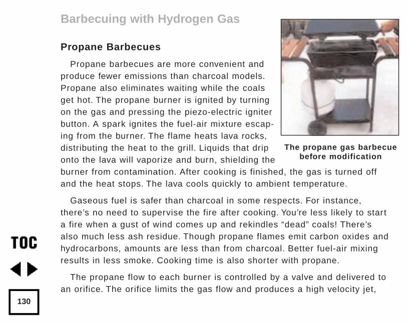
Propane Barbecues
Propane barbecues are more convenient andproduce fewer emissions than charcoal models.Propane also eliminates waiting while the coalsget hot. The propane burner is ignited by turningon the gas and pressing the piezo-electric igniterbutton. A spark ignites the fuel-air mixture escap-ing from the burner. The flame heats lava rocks,distributing the heat to the grill. Liquids that driponto the lava will vaporize and burn, shielding theburner from contamination. After cooking is finished, the gas is turned offand the heat stops. The lava cools quickly to ambient temperature.
Gaseous fuel is safer than charcoal in some respects. For instance,there’s no need to supervise the fire after cooking. You’re less likely to starta fire when a gust of wind comes up and rekindles “dead” coals! There’salso much less ash residue. Though propane flames emit carbon oxides andhydrocarbons, amounts are less than from charcoal. Better fuel-air mixingresults in less smoke. Cooking time is also shorter with propane.
The propane flow to each burner is controlled by a valve and delivered toan orifice. The orifice limits the gas flow and produces a high velocity jet,
Barbecuing with Hydrogen Gas
130
The propane gas barbecuebefore modification
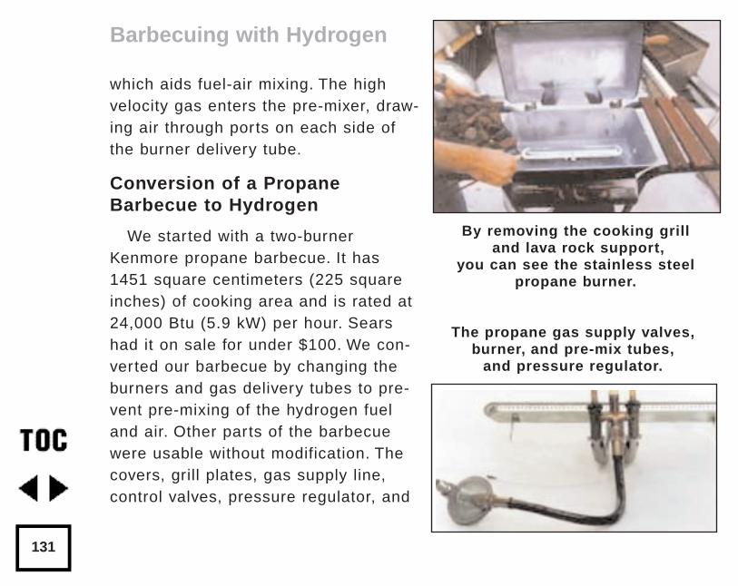
which aids fuel-air mixing. The highvelocity gas enters the pre-mixer, draw-ing air through ports on each side ofthe burner delivery tube.
Conversion of a PropaneBarbecue to Hydrogen
We started with a two-burnerKenmore propane barbecue. It has1451 square centimeters (225 squareinches) of cooking area and is rated at24,000 Btu (5.9 kW) per hour. Searshad it on sale for under $100. We con-verted our barbecue by changing theburners and gas delivery tubes to pre-vent pre-mixing of the hydrogen fueland air. Other parts of the barbecuewere usable without modification. Thecovers, grill plates, gas supply line,control valves, pressure regulator, and
Barbecuing with Hydrogen
131
By removing the cooking grilland lava rock support,
you can see the stainless steelpropane burner.
The propane gas supply valves,burner, and pre-mix tubes,
and pressure regulator.
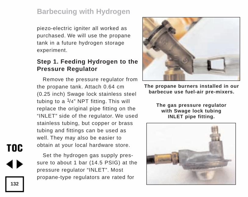
piezo-electric igniter all worked aspurchased. We will use the propanetank in a future hydrogen storageexperiment.
Step 1. Feeding Hydrogen to thePressure Regulator
Remove the pressure regulator fromthe propane tank. Attach 0.64 cm(0.25 inch) Swage lock stainless steeltubing to a 1/4” NPT fitting. This willreplace the original pipe fitting on the“INLET” side of the regulator. We usedstainless tubing, but copper or brasstubing and fittings can be used aswell. They may also be easier toobtain at your local hardware store.
Set the hydrogen gas supply pres-sure to about 1 bar (14.5 PSIG) at thepressure regulator “INLET”. Mostpropane-type regulators are rated for
Barbecuing with Hydrogen
132
The propane burners installed in ourbarbecue use fuel-air pre-mixers.
The gas pressure regulator with Swage lock tubing
INLET pipe fitting.
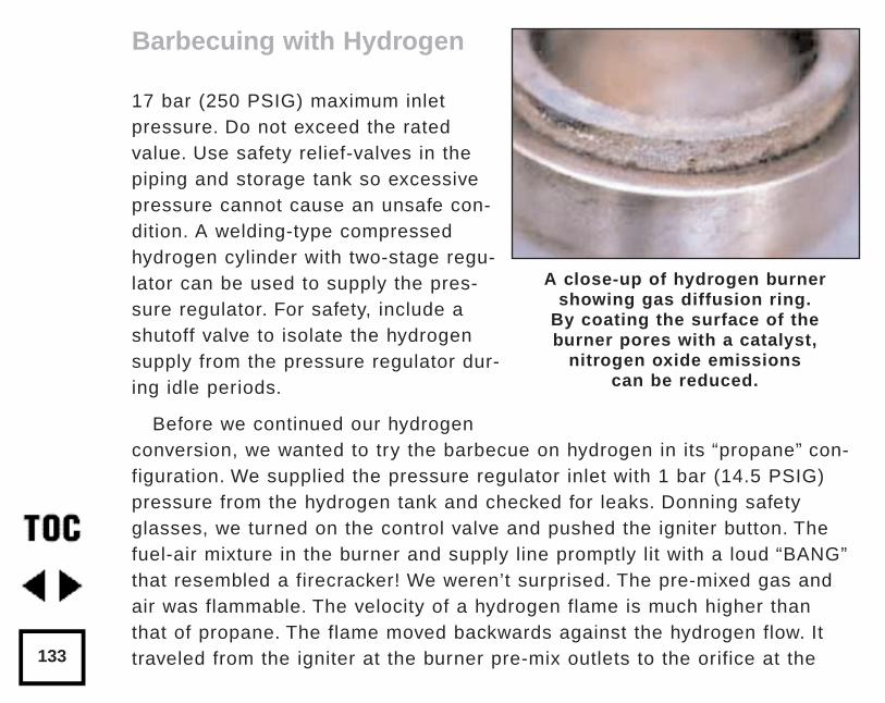
17 bar (250 PSIG) maximum inletpressure. Do not exceed the ratedvalue. Use safety relief-valves in thepiping and storage tank so excessivepressure cannot cause an unsafe con-dition. A welding-type compressedhydrogen cylinder with two-stage regu-lator can be used to supply the pres-sure regulator. For safety, include ashutoff valve to isolate the hydrogensupply from the pressure regulator dur-ing idle periods.
Before we continued our hydrogenconversion, we wanted to try the barbecue on hydrogen in its “propane” con-figuration. We supplied the pressure regulator inlet with 1 bar (14.5 PSIG)pressure from the hydrogen tank and checked for leaks. Donning safetyglasses, we turned on the control valve and pushed the igniter button. Thefuel-air mixture in the burner and supply line promptly lit with a loud “BANG”that resembled a firecracker! We weren’t surprised. The pre-mixed gas andair was flammable. The velocity of a hydrogen flame is much higher thanthat of propane. The flame moved backwards against the hydrogen flow. Ittraveled from the igniter at the burner pre-mix outlets to the orifice at the
Barbecuing with Hydrogen
133
A close-up of hydrogen burnershowing gas diffusion ring.
By coating the surface of the burner pores with a catalyst,
nitrogen oxide emissions can be reduced.
mixer. The flame burned freely on the open jet of hydrogen coming out ofthe orifice, heating the pre-mix tube instead of the burner. The hydrogen dif-fusion burner and gas distribution plate are designed to prevent the pre-mix-ing of hydrogen with air. In a gas diffusion burner, fuel is burned withoutpremixing the fuel (hydrogen) with air.
Pure hydrogen fuel passes out through the porous surface of the burner.The hydrogen and oxygen from the air then mix within the outer pores of theburner. This prevents flash-backs and keeps the flame from propagatingfrom the outer burner surface back into the fuel supply.
Step 2. Making The Burner
Machining the hydrogen gas distribution base from low carbon steelrequires the following steps:
1) For the gas diffusion ring, cut a circular groove with a shoulder step onthe outside. The step prevents the ring from being pressed all the way to thebottom of the circular groove.
2) Drill two long holes completely through the steel base at 90° to eachother. The holes will connect the gas feed fitting at the center of the burnerto four different locations around the circular gas distribution groove.
3) Tap the outermost ends of the four holes for 1/ 8” NPT pipe plugs.
Barbecuing with Hydrogen Gas
134
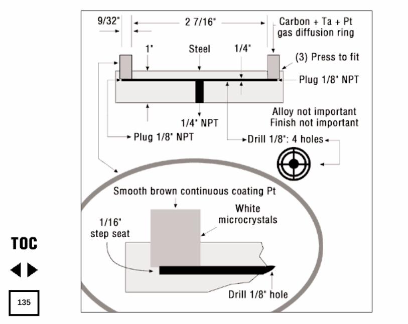
135
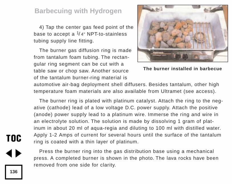
4) Tap the center gas feed point of thebase to accept a 1/ 4” NPT-to-stainlesstubing supply line fitting.
The burner gas diffusion ring is madefrom tantalum foam tubing. The rectan-gular ring segment can be cut with atable saw or chop saw. Another sourceof the tantalum burner-ring material isautomotive air-bag deployment shell diffusers. Besides tantalum, other hightemperature foam materials are also available from Ultramet (see access).
The burner ring is plated with platinum catalyst. Attach the ring to the neg-ative (cathode) lead of a low voltage D.C. power supply. Attach the positive(anode) power supply lead to a platinum wire. Immerse the ring and wire inan electrolyte solution. The solution is made by dissolving 1 gram of plat-inum in about 20 ml of aqua-regia and diluting to 100 ml with distilled water.Apply 1-2 Amps of current for several hours until the surface of the tantalumring is coated with a thin layer of platinum.
Press the burner ring into the gas distribution base using a mechanicalpress. A completed burner is shown in the photo. The lava rocks have beenremoved from one side for clarity.
Barbecuing with Hydrogen
136
The burner installed in barbecue
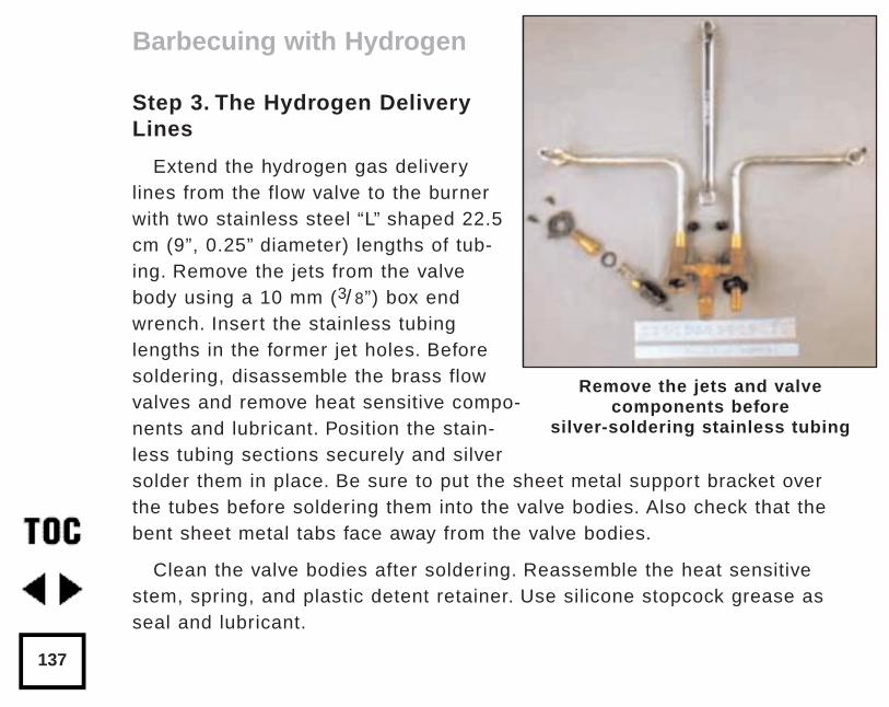
Step 3. The Hydrogen DeliveryLines
Extend the hydrogen gas deliverylines from the flow valve to the burnerwith two stainless steel “L” shaped 22.5cm (9”, 0.25” diameter) lengths of tub-ing. Remove the jets from the valvebody using a 10 mm (3/ 8”) box endwrench. Insert the stainless tubinglengths in the former jet holes. Beforesoldering, disassemble the brass flowvalves and remove heat sensitive compo-nents and lubricant. Position the stain-less tubing sections securely and silversolder them in place. Be sure to put the sheet metal support bracket overthe tubes before soldering them into the valve bodies. Also check that thebent sheet metal tabs face away from the valve bodies.
Clean the valve bodies after soldering. Reassemble the heat sensitivestem, spring, and plastic detent retainer. Use silicone stopcock grease asseal and lubricant.
Barbecuing with Hydrogen
137
Remove the jets and valve components before
silver-soldering stainless tubing
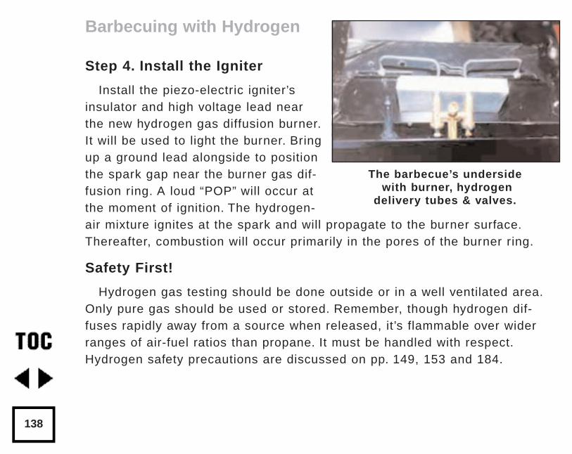
Step 4. Install the Igniter
Install the piezo-electric igniter’sinsulator and high voltage lead nearthe new hydrogen gas diffusion burner.It will be used to light the burner. Bringup a ground lead alongside to positionthe spark gap near the burner gas dif-fusion ring. A loud “POP” will occur atthe moment of ignition. The hydrogen-air mixture ignites at the spark and will propagate to the burner surface.Thereafter, combustion will occur primarily in the pores of the burner ring.
Safety First!
Hydrogen gas testing should be done outside or in a well ventilated area.Only pure gas should be used or stored. Remember, though hydrogen dif-fuses rapidly away from a source when released, it’s flammable over widerranges of air-fuel ratios than propane. It must be handled with respect.Hydrogen safety precautions are discussed on pp. 149, 153 and 184.
Barbecuing with Hydrogen
138
The barbecue’s undersidewith burner, hydrogen
delivery tubes & valves.
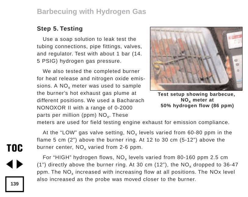
Step 5. Testing
Use a soap solution to leak test thetubing connections, pipe fittings, valves,and regulator. Test with about 1 bar (14.5 PSIG) hydrogen gas pressure.
We also tested the completed burnerfor heat release and nitrogen oxide emis-sions. A NOx meter was used to samplethe burner’s hot exhaust gas plume atdifferent positions. We used a BacharachNONOXOR II with a range of 0-2000parts per million (ppm) NOx. Thesemeters are used for field testing engine exhaust for emission compliance.
At the “LOW” gas valve setting, NOx levels varied from 60-80 ppm in theflame 5 cm (2”) above the burner ring. At 12 to 30 cm (5-12”) above theburner center, NOx varied from 2-6 ppm.
For “HIGH” hydrogen flows, NOx levels varied from 80-160 ppm 2.5 cm(1”) directly above the burner ring. At 30 cm (12”), the NOx dropped to 36-47ppm. The NOx increased with increasing flow at all positions. The NOx levelalso increased as the probe was moved closer to the burner.
Barbecuing with Hydrogen Gas
139
Test setup showing barbecue,NOx meter at
50% hydrogen flow (86 ppm)
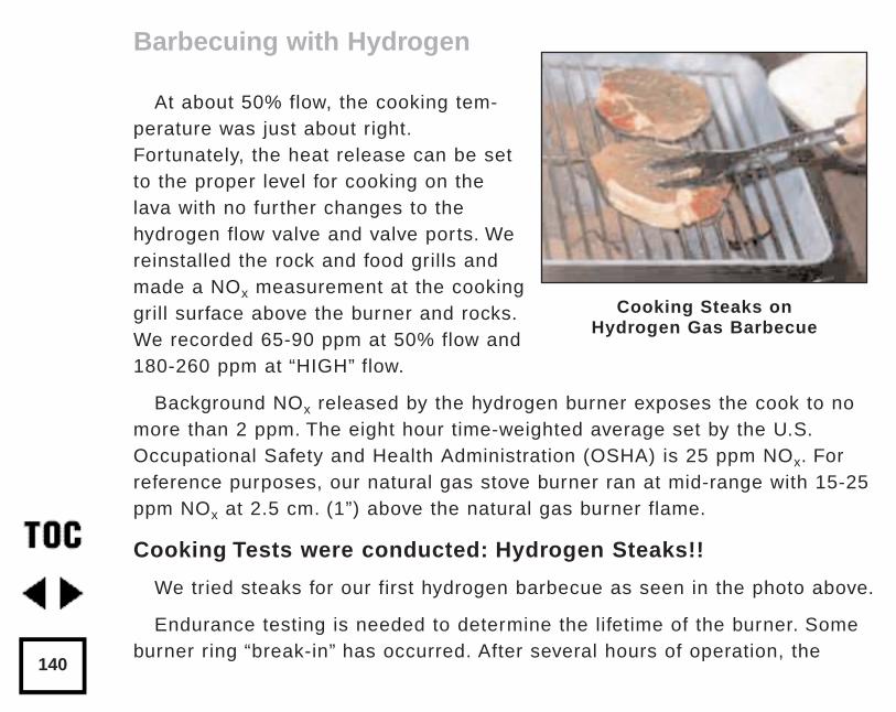
At about 50% flow, the cooking tem-perature was just about right.Fortunately, the heat release can be setto the proper level for cooking on thelava with no further changes to thehydrogen flow valve and valve ports. Wereinstalled the rock and food grills andmade a NOx measurement at the cookinggrill surface above the burner and rocks.We recorded 65-90 ppm at 50% flow and180-260 ppm at “HIGH” flow.
Background NOx released by the hydrogen burner exposes the cook to nomore than 2 ppm. The eight hour time-weighted average set by the U.S.Occupational Safety and Health Administration (OSHA) is 25 ppm NOx. Forreference purposes, our natural gas stove burner ran at mid-range with 15-25ppm NOx at 2.5 cm. (1”) above the natural gas burner flame.
Cooking Tests were conducted: Hydrogen Steaks!!
We tried steaks for our first hydrogen barbecue as seen in the photo above.
Endurance testing is needed to determine the lifetime of the burner. Someburner ring “break-in” has occurred. After several hours of operation, the
Barbecuing with Hydrogen
140
Cooking Steaks on Hydrogen Gas Barbecue
sharp edges of the gas diffusion ring have become rounded by excessiveheating. Whether this will stabilize remains to be seen. Lifting the rock grillhigher above the burner ring will probably reduce the reflected heat reach-ing the burner ring from the glowing lava.
Possible Future Improvements and Measurements
1) Coating the steel base to prevent rust caused by combustion watercondensation at startup and “LOW” hydrogen flows.
2) Venting the lid to prevent the buildup of an explosive mixture. Thiscould occur when the gas is “on”, the cover is closed, and ignition hasnot yet occurred. An interlock could be used to prevent hydrogen fromflowing to the burner when the barbecue cover is closed and the flamehas not yet been lit.
3) Measuring the flow rate of the hydrogen gas delivered to the burnerat different valve settings.
4) Measuring the temperature of the burner surface at different hydro-gen flow valve settings.
Acknowledgements
Ultramet, for the foam tantalum and silicon carbide tubing samples.
A&K Machine Shop, Richmond, California for machining the burner gasdistribution plate.
Barbecuing with Hydrogen Gas
141
AccessAuthors:
Walt Pyle WA6DUR 510-237-7877,
John Dabritz 510-242-5366,
Reynaldo Cortz 510-237-9748,
and Jim Healy WH6LZ 510-236-6745
Diffusion Burners for Hydrogen:Fraunhofer-Gesellschaft Institute for Solar Energy Systems, Tel:(Freiberg, Germany) 49-761-4014-0 Ext. 164 or 210.FAX: 49-761-4014-100
Diffusion Ring Tubing:Ultramet, 12173 Montague Street, Pacoima, CA • 818-899-0236 FAX 818-890-1946
Chemical supplies (platinum powder and wire, aqua-regia):Aldrich Chemical Co., 1001 W St Paul Ave, Milwaukee, WI 53233 •800-558- 9160
Barbecuing with Hydrogen Gas
142
by Walt Pyle, Jim Healy, Reynaldo Cortez, & David BoothOriginally published in Home Power #34 • April / May 1993© 1993 Walt Pyle, Jim Healy, Reynaldo Cortez, & David Booth
We want to share our experiments running a catalytic space-heater onhydrogen fuel. Three space-heaters are now installed in various rooms ofone of the author’s Richmond, California home. They are currently fueledwith natural gas. These heaters present an almost ideal opportunity for con-version to hydrogen combustion. We plan to operate these space heatersroutinely in the near future on hydrogen produced at home.
Gas Appliance Conversion
In the chapter “Cookin’ On Hydrogen” (p.118), we examined an approachfor modifying conventional kitchen stove burners (intended for natural gas orpropane use) to allow cooking on hydrogen fuel. This method involved usingstainless steel wool as a catalyst, and delivering hydrogen to the burnerhead without pre-mixing the fuel with air. The originators of this techniquerefer to this approach as “flame assisted catalytic combustion of hydrogen.”
In this article we’d like to focus on pure catalytic combustion of hydrogenand air. Catalytic combustion of hydrogen and air can occur in the presenceof certain noble metal catalysts (such as platinum or palladium), without anyflame whatsoever. Water vapor and heat are byproducts of the reaction.
Heatin’ with Hydrogen
143
The Platinum CAT™
Catalytic space-heaters are availableas mass-produced, low-cost consumerappliances. Some are intended forpropane and some are for natural gasfuel. We chose to work with a PlatinumCAT™ catalytic space-heater since itwas the only model with forced externalventing and an American GasAssociation approval. Our intended application was for a home, not a recreational vehicle.
The manufacturer of the Platinum CAT™ flameless, catalytic, radiantspace-heater is Thermal Systems, Inc. of Tumwater, Washington. Thepropane versions were conceived with the recreational vehicle market inmind, so they rely on 12 VDC power. The natural gas models are very simi-lar in overall design, but they require 120 vac for operation of the solenoidgas valve and blower fan. Both types require a vent to the outdoors for theexhaust gases.
Our Platinum CAT™ was a Model 1500 120 vac 60 Hz version with a gasorifice sized for pipeline natural gas. (Model 1500 can also run on propane
Heatin’ with Hydrogen
144
with the correct orifice installed.) The first CAT was installed in the livingroom during 1991 and operated for one year on natural gas to gain serviceexperience. We were so pleased with its performance that we ordered andinstalled two more CATs during 1992.
Multiple Benefits
The radiant heat available from the Platinum CAT™ is long wavelengthinfra-red radiation similar to the sun’s own rays. Radiant heat, unlike convec-tion or conduction heat, is transmitted through space, and only releases itsenergy when the rays strike objects and/or people. Warmth from this space-heater is felt immediately, unlike forced air convection systems which firstmust heat the surrounding air.
The efficiency of catalytic hydrogen-air combustion with platinum catalysisis extremely high. The range of efficiencies commonly reported in technicalliterature is 85 - 100%. Efficiency is high because the combustion takesplace at a substantially lower temperature than under ordinary conditions.This means in the presence of the platinum catalyst, no pilot light, spark, orglow plug is needed to initiate flameless combustion. This important safetyfeature helps prevent the accidental buildup of unburned gas and air mix-tures. Also, catalytic combustion occurs far below the threshold temperatureat which oxygen and nitrogen can react to form polluting nitrogen oxides
Heatin’ with Hydrogen
145
(NOx). As a result, these emissions are 0.1 parts per million (ppm) or lesscompared to conventional burners at 200 to 300 ppm.
In the future, we will take full advantage of the higher heating value ofhydrogen. This can be accomplished if the byproduct - water in the vaporstate - changes back to a liquid and gives up its heat before it leaves theheated space. This is called the latent heat of condensation.
Conversion of The Platinum CAT™ to Hydrogen
These space heaters can be modified for the direct use of pure hydrogenby controlling the feed flow rate of hydrogen gas (and thus the heat releaserate). The hydrogen flow rate to the Platinum CAT™ can be adjusted by rais-ing or lowering the delivery pressure, or by resizing the gas inlet orifice. Itmay not be necessary to adjust anything if you are content with less outputfrom the space heater.
Piping and Wiring the CAT
An excellent instruction and installation manual comes with the PlatinumCAT™. The installation must conform to local codes. In the absence of localcodes, the installation must conform with American National Standard(National Fuel Gas Code) known as NFPA 54 and ANSI Z223.1 1984. Weused threaded 3/ 4” black iron pipe for the fuel delivery line with a high
Heatin’ with Hydrogen
146
quality thread sealer (Permatex Industrial Hydraulic Sealer). A fuel gasshut-off valve was installed at the appliance entrance flex hose.
A 2” plastic flue pipe was used since the flue gases are low temperaturewith the fan running. The heater will not open the fuel gas solenoid valveunless the fan is running. No provision was made for condensed waterremoval, since we are operating the unit in a mild climate where this isnot a problem.
A soap solution was used for leak testing the piping after installation. Aproduct useful for this purpose is called Rectorseek Leak Detector(Rectorseal Corporation). A thermostat is supplied with the unit to controlthe temperature in the room. It works by turning the space heater “on” or“off ” as required. We mounted our thermostat at the upper right of each unitso the wires could be hidden behind the heater frame. With this configura-tion we found that one must set the thermostat to a higher temperature thanthat desired for the room. The thermostat is heated by local conductionsomewhat and tends to shut off prematurely. Placing the thermostat furtheraway from the space-heater would benefit some installations.
The control unit for our natural gas approved Platinum CAT™ had a 120vac power card, so we just plugged it in and we were “on the air”!
Heatin’ with Hydrogen
147
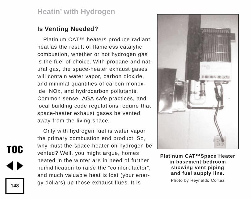
Is Venting Needed?
Platinum CAT™ heaters produce radiantheat as the result of flameless catalyticcombustion, whether or not hydrogen gasis the fuel of choice. With propane and nat-ural gas, the space-heater exhaust gaseswill contain water vapor, carbon dioxide,and minimal quantities of carbon monox-ide, NOx, and hydrocarbon pollutants.Common sense, AGA safe practices, andlocal building code regulations require thatspace-heater exhaust gases be ventedaway from the living space.
Only with hydrogen fuel is water vaporthe primary combustion end product. So,why must the space-heater on hydrogen bevented? Well, you might argue, homesheated in the winter are in need of furtherhumidification to raise the “comfort factor”,and much valuable heat is lost (your ener-gy dollars) up those exhaust flues. It is
Heatin’ with Hydrogen
148
Platinum CAT™Space Heaterin basement bedroom showing vent piping and fuel supply line.Photo by Reynaldo Cortez
tempting then, to think about venting the space-heater into the room. Weadvise against this practice.
Dangerous and harmful situations could arise if a space-heater on hydro-gen (or conventional fuels) is not vented to the outdoors:
• Excessive moisture could condense in the home causing damage tobuilding materials and the growth of unwanted bioorganisms.
• Loss of oxygen in the breathing atmosphere of a tightly sealed or“superinsulated” home could lead to asphyxiation or loss of conscious-ness for occupants.
• Confinement of a potentially explosive mixture of hydrogen and air ispossible.
A simple well designed vent can prevent these problems from occurringwith any hydrogen appliance. The vent system (shown in photo on the previ-ous page) was made for our second Platinum CAT™ space-heater, which weinstalled in 1992 in a basement bedroom.
Our Experience to Date
During the summer of 1991 we made the first test of the Platinum CAT™using hydrogen fuel. The hydrogen came from a high pressure compressedgas cylinder followed by a two stage pressure regulator. This allowed us to
Heatin’ with Hydrogen
149
drop the pressure from as high as 2300 psig (pounds per square inch gauge)down to a pressure of about 4” of water column (w.c.), suitable for a gasappliance. We found that the hot wire starter for natural gas operation wasunnecessary for initiation of hydrogen-air catalytic combustion. The hydrogengas reacted with air on contact with the platinum coated silica quatz pad,giving off about as much heat as when running on natural gas.
A few weeks later, we contacted Thermal Systems, the manufacturer of thePlatinum CAT™, and discussed operation on hydrogen with Arnie Lind, theirresident R&D Lab Engineer. Arnie was interested in our approach. A fewweeks later when we talked again, Arnie told us about some experiments hehad run in the lab using hydrogen in a Platinum CAT™. Arnie became evenmore interested in the hydrogen fuel space heater after talking to SandyStuart from Electrolyser Corporation in Canada (to whom we had provided acopy of the Platinum CAT™ literature). Arnie confirmed that he had reliablyobtained catalytic combustion of hydrogen and air without the ignitor, within45 seconds or less after he turned the Platinum CAT™ on. Using a 5” w.c.hydrogen supply pressure to the Platinum CAT™, Arnie measured fuel con-sumption of about 16 cubic feet per hour. On natural gas, the fuel consump-tion was about 5 cubic feet per hour using 4” w.c. pressure at rated output of5200 BTU/hour. An even combustion pattern was seen on the silica quartzpad face, glowing a dull orange when viewed in a dark room. Arnie found
Heatin’ with Hydrogen
150
that he could get the same heat release as natural gas if he enlarged thenatural gas orifice (normally 0.043”) to 0.052” (drill size #55).
One of Arnie Lind’s primary concerns was in testing to assure that thesurface of the catalyst silica quartz pad was not damaged by overheating(temperatures greater than 1100°F were known to cause problems). Byusing a non-contact infrared thermometer he found that the surface temper-ature of the rock wool was only 600° to 800°F when operating on hydrogenat the rated heat input, and not a problem. Another of Arnie’s concerns wasabout the flue gas composition. He planned to obtain samples of the gas foranalysis. Maybe there will be an AGA approved hydrogen Platinum CAT™ inour future! We hope so.
Demonstrating Flameless Combustion
We shared the news of this novel appliance with David Katz of AlternativeEnergy Engineering. He proceeded to order one for his home, but initially itbecame our handy demonstrator unit for a recent alternative energy fair anda one day hydrogen workshop. Even without plumbing or wiring this device,we amazed more than a few curious souls and skeptics with a simpledemonstration of flameless combustion. After removing the protective grillon the heater, a silica quartz pad with minute amounts of platinum is leftexposed. All that was needed to instantaneously produce heat and a
Heatin’ with Hydrogen
151
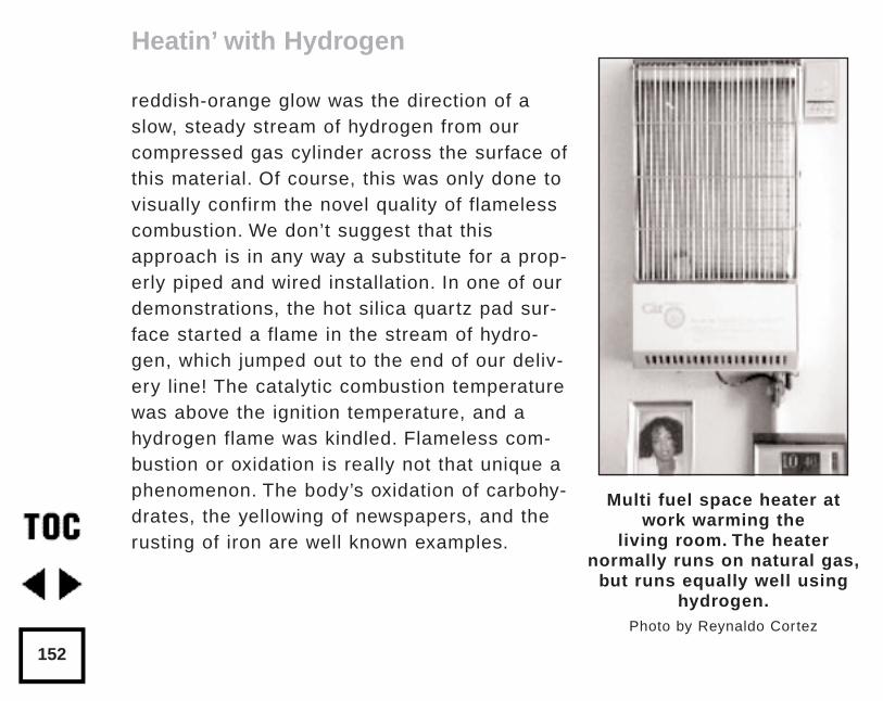
reddish-orange glow was the direction of aslow, steady stream of hydrogen from ourcompressed gas cylinder across the surface ofthis material. Of course, this was only done tovisually confirm the novel quality of flamelesscombustion. We don’t suggest that thisapproach is in any way a substitute for a prop-erly piped and wired installation. In one of ourdemonstrations, the hot silica quartz pad sur-face started a flame in the stream of hydro-gen, which jumped out to the end of our deliv-ery line! The catalytic combustion temperaturewas above the ignition temperature, and ahydrogen flame was kindled. Flameless com-bustion or oxidation is really not that unique aphenomenon. The body’s oxidation of carbohy-drates, the yellowing of newspapers, and therusting of iron are well known examples.
Heatin’ with Hydrogen
152
Multi fuel space heater atwork warming the
living room. The heaternormally runs on natural gas,
but runs equally well usinghydrogen.
Photo by Reynaldo Cortez
Safety Warning
Please be forewarned that although our experience may indicate that sucha conversion is relatively simple, the use of this appliance with hydrogen fuelis not yet approved by the manufacturer. Approval from the American GasAssociation must be obtained before the Platinum CAT™ on hydrogen will be ready for commerce. The use of any gaseous fuel in a space heater,other than the one recommended specifically by the manufacturer will void the warranty, and may not comply with American Gas Association (AGA)safe practices.
If you want to try any hydrogen space-heater experiments on your own, beaware:
• Installation should only be done by a qualified service person.
• Any changes to the heater or its controls, or attempts to clean the catalytic pad can result in damage, defective operation, andmay be dangerous.
• Any experiments with hydrogen fuel should be done outside.
• Hydrogen gas is odorless; you cannot smell a leak.
• Remember that hydrogen gas and air mixtures are potentially combustibleand explosive over wide mixture ratios (4 to 75% hydrogen in air). Onlypure gases should be stored, never mixtures of hydrogen and air.
Heatin’ with Hydrogen
153
AccessAuthors:
David Booth, Alternative Energy Engineering, PO Box 391, Miranda,CA 95553 • 707-923-4336
Walt Pyle, WA6DUR, Richmond, CA • 510-237-7877
Jim Healy, KD6LYV, Richmond, CA • 510-236-6745
Reynaldo Cortez, Richmond, CA • 510-237-9748
Platinum CAT™ Heater:Thermal Systems Inc., Mottman Industrial Park, 2757 29th St. SW,Tumwater, WA 98502 • 206-352-0539
Safety Regulations:NFPA 54 and ANSI Z223.1 1984 from:American National StandardsInstitute Inc., 1430 Broadway, New York, NY 10018 or National FireProtection Assoc., Batterymarch Park, Quincy, MA 02269
Heatin’ with Hydrogen
154
by David BoothOriginally published in Home Power #35 • June / July 1993© 1993 David Booth
Fuel cells are likely to replace internal combustion engines in the nextcentury. Internal combustion (IC) engines and fuel cells are both energyconverters which transform chemical energy into a more usable form ofenergy. Fuel cells are electrochemical devices which efficiently convertchemical energy into DC electricity and some heat (thermal energy). ICengines transform chemical energy into mechanical energy and a substan-tial amount of heat.
Energy Converters
Coupling a fuel cell to an electric motor produces mechanical energy.Similarly, an IC engine produces electrical energy if we couple it to an alter-nator or dynamo. Fuel cells offer an incredible efficiency advantage over ICengines, especially gasoline engines in stop-and-go service. Atmosphericpollution could be greatly reduced with the use of fuel cells. These clearadvantages may ultimately cause the bell to toll for the internal, infernalcombustion engine.
Understanding Fuel Cells
155
All Fuel Cells are not the Same
Typically, fuel cells are categorized according to the kind of electrolytewhich is utilized within these devices. The electrolyte may consist of a liquidsolution or a solid membrane material. In any case, the electrolyte servesthe vital function of ionic transfer of electrical charge. Some of the technolo-gies are relatively advanced while others are still in their infancy. There arebasically five fuel cell versions:
Phosphoric acid fuel cells (PAFC)
Alkaline fuel cells (AFC)
Molten carbonate fuel cells (MCFC)
Solid oxide fuel cells (SOFC)
Proton exchange membrane fuel cells (PEMFC)
The proton exchange membrane fuel cell is a promising candidate forstand-alone home power generation.
PAFCs: The Most Mature Approach
Phosphoric acid fuel cells (PAFCs) probably represent the most maturefuel cell technology. Westinghouse, International Fuel Cells, and at least atrio of Japanese manufacturers have been refining the design of mid-sized
Understanding Fuel Cells
156
PAFC cogeneration plants. They are intended to fill the niche for stand-alonepower generation for utility substations, factories, restaurants, hotels, andhospitals.
The fuel choice for PAFCs is not restricted to pure hydrogen. Typically,these near-term plants will use natural gas, methanol, or light distillatesderived from fossil fuel sources. These cells operate at moderate tempera-tures (less than 200°C) with auxiliary reformers. Reformers convert thehydrocarbons to a mixture of hydrogen and carbon dioxide gases for thecells. The requirement for the initial reformation step sacrifices some effi-ciency, but the advantage of PAFCs is that they are tolerant of CO2 andother reformate impurities. The overall efficiency improves above the 40-50% range if the installations are used as cogeneration plants, and thewaste heat is used to make hot water and/or steam.
AFCs: Extraterrestrial & Terrestrial Applications
Another fuel cell technology which has been with us since the 1960s isthe alkaline fuel cell (AFC) system. AFCs were first developed for space-flight applications as part of the Gemini program to produce reliable on-board power and fresh water for the astronauts. International Fuel Cells andSiemens are currently major players in this field.
Understanding Fuel Cells
157
AFCs operate at relatively low temperatures, and don’t require noblemetal catalysts, strong advantages in their favor. Highly purified hydrogen,such as electrolytic hydrogen, is required as the fuel source. Unfortunately,AFCs also require pure oxygen as the oxidant, not air. AFCs are intolerantof even meager amounts of CO2 which effectively poisons them. If air is tobe used as the oxidant, expensive CO2 scrubbers would have to be used toprevent a degradation of AFC performance.
The use of AFCs in transportation applications is doubtful; it is generallyassumed that oxygen will not be stored on-board light vehicles. In home sys-tems with solar hydrogen production, oxygen will also be produced in mostcases, so this may not be a problem.
MCFCs: The New Hot Shots on the Block
Little will be said here about molten-carbonate fuel cells (MCFCs) andsolid-oxide fuel cells (SOFCs). These second generation fuel cell strategiesrequire very high temperatures for operation, (600°-1200°C). This allows forthe internal reformation of fuels such as natural gas, methanol, petroleum,and coal. These devices tolerate CO2 without requiring any further treatmentand are possible substitutes for large to mid-sized thermal power plants,substations, or as cogenerators for factories. MCFCs and SOFCs are lesslikely to be utilized for remote home power generation by you or me, even inthe distant future.
Understanding Fuel Cells
158
PEMFCs: Promise for Home Power Generation
One remaining fuel cell design approach has been saved for last. It is thesolid polymer fuel cell, perhaps more commonly referred to as the protonexchange membrane fuel cell (PEMFC). This technology deserves the mostcareful scrutiny by advocates of decentralized renewable energy and alter-native transportation.
Proton exchange membrane fuel cells (PEMFCs) appear to be the “newkids on the block”. In reality they represent a technology that was vir tually“forgotten” for about a decade. This was an area of fuel cell research thatlanguished in relative obscurity, and which received minimal R&D fundinguntil only recently. General Electric pioneered the early work. The interestreally revived in the last few years when Ballard Power Systems ofVancouver B.C., Canada went public with their results. Other private organi-zations which have gotten into the act in recent years include: H-Power,Ergenics, Energy Partners, Lynntech, Siemens, and Billings (InternationalAcademy of Science). United States educational and public institutionswhich have on-going laboratory research in this field include the SchatzFuel Cell Project at California State University at Humboldt, the Center forElectrochemical and Hydrogen Research at Texas A&M, and Los AlamosNational Laboratory. New players are entering and exiting this field so frequently that this lineup may already be out of date.
Understanding Fuel Cells
159
Elegant Simplicity
One can hardly examine PEMFCs without being impressed with their ele-gantly simple design concept. Yet, closer study reveals their complexities andpotential pitfalls in operation. Although PEMFCs are currently available com-mercially from a few vendors on special order, don’t rush for your checkbooksunless you have deep pockets and a strong heart. PEMFCs are currently inthe prototype development stage, although laboratory research continues as well.
So, most of us must exercise a little patience for the vast promise of thesedevices to be fulfilled. Unless, that is, you’re an impatient do-it-yourselfer, and choose to follow in the footsteps of others like Walt Pyle, ReynaldoCortez, Alan Spivak, and Jim Healy who have built an operational single cellPEMFC. A detailed description of their procedures can be found in the nextchapter “Making Electricity with Hydrogen” (p.169).
A Look Inside PEMFCs
The similarity between fuel cells and electrolyzers may be apparent fromthe illustration below. As Rob Wills points out in “Hydrogen Fuel Cells - thePower Source of the 90s” (p.223), fuel cells are essentially electrolyzers oper-ating in reverse. Both of these electrochemical cells share certain internalelements along with batteries. They all have negatively charged electrodes,
Understanding Fuel Cells
160
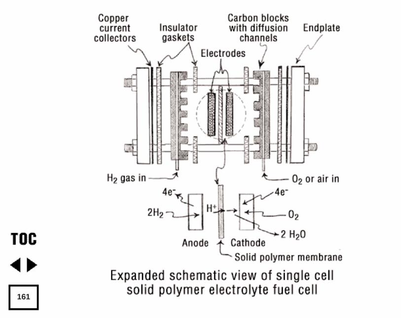
161
positively charged electrodes, and an electrolyte that conducts charged ionsbetween the electrodes.
Hydrogen is introduced into a PEMFC through a porous conductive elec-trode, which is frequently composed of graphite (carbon). The porous con-ductors may consist of special carbon paper. They may be graphite blocksmilled with many gas delivery channels. The porous conductors may even beformed by pressing a carbon powder with a binder into a die with sufficientheat and pressure. The particular type of porous conductor construction isdetermined by the size and complexity of the cell or cell stack.
Gas Separator and Ion Conductor
The solid polymer electrolyte membrane makes the PEMFC unique. Mostcurrent prototypes of PEMFCs use either a Nafion membrane from DuPontor one that is simply referred to as the “Dow membrane”. Each is a perfluo-ronated sulfonic acid polymer, but the Dow membrane is said to have moresulfonate side chains. There are even other versions by Asahi Chemical andChloride Engineers, Inc. The simple beauty of this design is that the mem-brane acts both as a conductor of hydrogen protons, and as a separator tokeep the reacting gases from mixing and combusting. This feature allows forcompact, lightweight cells, because the membranes themselves are verythin (0.007—0.015”).
Understanding Fuel Cells
162
A sheet of Nafion 117 doesn’t look much different than a thick sheet ofpolyethylene or Saran Wrap. Onto this Nafion substrate is deposited a dis-persed coating of platinum, a noble metal catalyst. This facilitates the chemi-cal reactions, so they proceed at lower temperatures. Approaches which havebeen used with success for depositing the platinum include: thin film vacuumprocesses, brushing or precipitating a dilute solution of chloroplatinic acid,and hot pressing powders (carbon, platinum, and teflon). Significant reduc-tions in the amount of expensive platinum have apparently been achieved,from 20 mg/cm2 to 0.4 mg/cm2 , without sacrificing performance.
Seen from a Molecule’s Point-of-View
Okay, now we’re ready to travel the inner journey traversed by individualhydrogen and oxygen molecules on the path to their new union (see figure).If we introduce pure hydrogen through the porous conductive hydrogen elec-trode, it arrives as a diatomic gas, H2 . Each molecule is dissociated into twohydrogen atoms and stripped of two electrons as it interacts with the catalyt-ic surface of the membrane. Devoid of their electrons, they exist as two H+,hydrogen protons. The membrane itself will not conduct electrons. However,the electrons will flow readily via the conductive hydrogen electrode throughthe external circuit to the opposite oxygen electrode. Along this path, the cur-rent may flow through an external load accomplishing work. Meanwhile, the
Understanding Fuel Cells
163
protons are moving their way through the solid polymer electrolyte on theirway to meet oxygen ions. Simultaneously, diatomic oxygen molecules, O2,are diffusing through the oxygen electrode where they contact the platinizedsurface on the opposite side of the membrane. Here we would find that oxy-gen molecules separate into oxygen atoms which are held momentarily in a“receptive” state on the active platinum. Once electrons coming from theload meet the two protons arriving at this site, they combine with the oxygenatom in a spontaneous union. Voila! This results in the formation of one mol-ecule of water, H2O.
Only one half as much oxygen is needed in this process as is needed ofhydrogen. A chemist might write a synopsis of the entire process as shownbelow. The reaction at the hydrogen electrode of a PEMFC:
2H2 ––> 4H ––> 4 electrons + 4H+
The reaction at the oxygen electrode of a PEMFC:
O2 ––> 2O
then,
4 electrons + 4H + + 2O ––> 2H2O
The overall reaction within a PEMFC is simply
2H2 + O2 ––> 2H2O.
Understanding Fuel Cells
164
What’s the Rub?
Well, this works very well in theory, but there is a little more to the story.In actual practice there are some additional complications involved inPEMFC operation. First, the hydrogen which is introduced into the cell mustbe saturated with H2O vapor or else the membrane will dry out on the hydro-gen side hindering performance markedly. Second, on the opposite side ofthe membrane a delicate balance must be struck with humidification also.Water is continually forming on the oxygen side which aids hydration of themembrane. But if droplets of water condense on the active surfaces, thereaction rate can slow to a halt as the cell literally drowns in its end product.Some waste heat is also building up simultaneously, even though theprocess is usually between 55-80% efficient. It is primarily the need formoisture and thermal management of both sides which has plagued a num-ber of the PEMFC designs. Leakage of gases around gaskets or o-rings isanother difficulty. As series cell stacks are built up of adjacent cells in abipolar configuration to produce useful output voltages, these problems maymagnify several fold.
So What is the Prognosis?
There is every reason to believe that the operational difficulties encoun-tered in PEMFCs will be solved in the near future. The progress needed to
Understanding Fuel Cells
165
make these fuel cells viable should not require any major “technologicalbreakthroughs”. PEMFCs hold great promise for automotive and other trans-portation applications, because they should prove to be both light and com-pact as well as extremely efficient compared to internal combustion engines.
When transportation energy analysts compare various drive train systemsfor future automobile designs, they frequently speak of criteria such as ener-gy density and power density. Energy density is commonly expressed inunits such as kWhr/kg, whereas power density pertains to the ability of asystem to deliver performance quickly, and is expressed as kW/kg. Sincefuel cells themselves do not produce torque, they would need to be coupledwith highly efficient electrical motors. The coupling of hydrogen stored on-board an automobile as a liquid, hydride, or compressed gas with PEMFCswould seem to have superior energy density as an integral system than anybattery electric vehicle configuration on the horizon. However, in order forthese fuel cell vehicles to come close to matching the power of today’s inter-nal combustion engine vehicles, perhaps the best configuration would be ahybrid one. These hybrids would likely use a “base load” fuel cell for cruisingwith a quick discharging battery for the higher instantaneous demands ofacceleration. This is exactly the conclusion arrived at by three independentresearch analysts, and published in two scientific papers which have recent-ly been published (see references).
Understanding Fuel Cells
166
The Pregnant Promise of Fuel Cells
We can only hope that fuel cell research coupled with engineering refine-ments continues at an accelerated pace. The inefficiency of the internalcombustion engine cannot be tolerated much longer. Atmospheric pollution,global warming resulting from greenhouse gas emissions, and the steadilydeclining reserves of petroleum are all part of the legacy left us by depend-ence on fossil fueled IC engines. Many scientists and energy analystsbelieve that a solar based hydrogen energy system is the answer to theseproblems. The timely maturity of hydrogen fuel cell technologies will be ofcritical significance, if the world is going to successfully wean itself fromfossil fuels. An appropriate analogy might be made between the develop-ment of integrated circuits and fuel cells. The first integrated circuits were alandmark advance that ushered in the electronic and information age. Asfuel cells replace IC engines, I believe a Solar Hydrogen Age will blossomfrom the dust of the passing fossil fuel era.
AccessAuthor:
David Booth, Alternative Energy Engineering • 707-923-4336
Further readingHydrogen Fuel-Cell Vehicles, Mark DeLuchi, Institute of TransportationStudies, University of California, Davis, CA 95616
Understanding Fuel Cells
167
Further reading (continued)The International Journal of Hydrogen Energy, Permagon Press.Contact P.O. Box 248266, Coral Gables, FL 33124
Hydrogen-Fueled Vehicles Technology Assessment Report forCalifornia Energy Commission, Dr. David Swan and Debbi L. Smith,Technology Transition Corporation and Center for ElectrochemicalSystems and Hydrogen Research, Texas A&M University, 238Wisenbaker ERC, College Station, TX 77843
Chapter
168
by Walt Pyle, Alan Spivak, Reynaldo Cortez, and Jim HealyOriginally published in Home Power #35 • June / July 1993© 1993 Walt Pyle
A gas fed battery that never needs recharging! This article describes aprocess for building a fuel cell using tools and techniques any skilled hobby-ist with a well-equipped shop can duplicate. The fuel cell that we built canproduce direct current electricity from stored hydrogen and oxygen. Weobtained the hydrogen for this fuel cell commercially but plan to producehydrogen and oxygen from a renewable energy system based on solar pho-tovoltaics and water electrolyzers.
Cookbook Approach to Building a Fuel Cell
In this article we reveal the process we used to make a proton exchangemembrane (PEM) fuel cell. First, we describe what the PEM material is, andwhere to get it. Then we cover the steps necessary for preparing the mem-brane to use it in a fuel cell. Next, we describe the catalyst and bindersused on both sides of the PEM and the method of “hot-pressing” them alltogether to form the single fuel cell catalyst-PEM-catalyst “sandwich”.Finally, the holder for the catalyzed PEM fuel cell with its gas supply piping,insulators, and wiring studs is shown.
Making Electricity with Hydrogen
169
Some PEM fuel cell performance data were obtained using an electricalresistor to provide a variable load. Two digital multimeters and a shunt resis-tor were used to measure the voltage and current, so we could calculate thepower produced. Although the fuel cell described produces a relatively lowvoltage, several fuel cells of this kind can be wired in series to producehigher voltages and do useful work.
The PEM Material
The PEM (proton exchange membrane) material is a perfluorosulfonic acidpolymer film. Several manufacturers make PEMs in one form or another. Weused one made by du Pont called Nafion 117. Nafion 117 is a transparentpolymer film about 175 microns (0.007”) thick. Dow Chemical Co., AsahiChemical Co., and Chloride Engineers Ltd. make something similar. A patentdescribing how one PEM manufacturer’s film is processed is listed in thereferences section at the end of this article. The basic structural unit formulafor Nafion 117 is shown below:
CF2 = CFOCF2CFOCF2CF2SO3H\
CF3
Nafion 117 contains fluorine, carbon, oxygen, sulfur, and hydrogenarranged in repeating polymer molecules. The hydrogen atom on the SO3
part of the molecule can detach from one SO3 site. The free H+ proton can
Making Electricity with Hydrogen
170
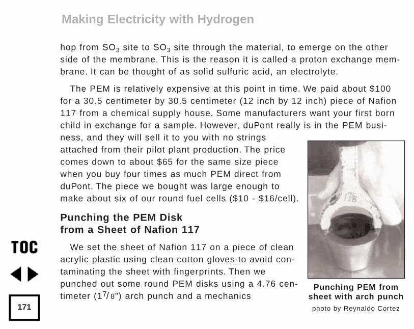
hop from SO3 site to SO3 site through the material, to emerge on the otherside of the membrane. This is the reason it is called a proton exchange mem-brane. It can be thought of as solid sulfuric acid, an electrolyte.
The PEM is relatively expensive at this point in time. We paid about $100for a 30.5 centimeter by 30.5 centimeter (12 inch by 12 inch) piece of Nafion117 from a chemical supply house. Some manufacturers want your first bornchild in exchange for a sample. However, duPont really is in the PEM busi-ness, and they will sell it to you with no stringsattached from their pilot plant production. The pricecomes down to about $65 for the same size piecewhen you buy four times as much PEM direct fromduPont. The piece we bought was large enough tomake about six of our round fuel cells ($10 - $16/cell).
Punching the PEM Disk from a Sheet of Nafion 117
We set the sheet of Nafion 117 on a piece of cleanacrylic plastic using clean cotton gloves to avoid con-taminating the sheet with fingerprints. Then wepunched out some round PEM disks using a 4.76 cen-timeter (17/ 8”) arch punch and a mechanics
Making Electricity with Hydrogen
171
Punching PEM fromsheet with arch punch
photo by Reynaldo Cortez
hammer filled with lead powder. After one or two tries, we found that severalstrikes with the hammer at different angles was best for cutting the disk freefrom the sheet. Striking the punch too hard shattered the acrylic sheet.
Handle the PEM with tweezers or forceps to prevent contamination. Weused a pair of stainless steel tweezers which were ground flat and polishedon the grasping faces to eliminate burrs and prevent puncturing or dentingthe soft PEM. Grasp the PEM disks only on the outer peripheral edge, neveron the inner active area.
Preparing the PEM for Catalyst Application
We prepared the film for catalyst application by dipping it in six differentheated solutions in glass beakers. The solutions were all held at 80°C(176°F) by immersing the beakers in a heated pan of water on top of two gasstove burners as shown above right. Each beaker held the PEM film for onehour in sequence. Use safety glasses and gloves while working with the solu-tions. The sequence of beakers used to dip the PEM was set up as follows:
Beaker 1 = 100 milliliters of distilled water [hydrate the membrane anddissolve surface contaminants].
Beaker 2 = 100 milliliters of 3% hydrogen peroxide solution (USP)[remove organic contaminants from PEM surface].
Making Electricity with Hydrogen
172
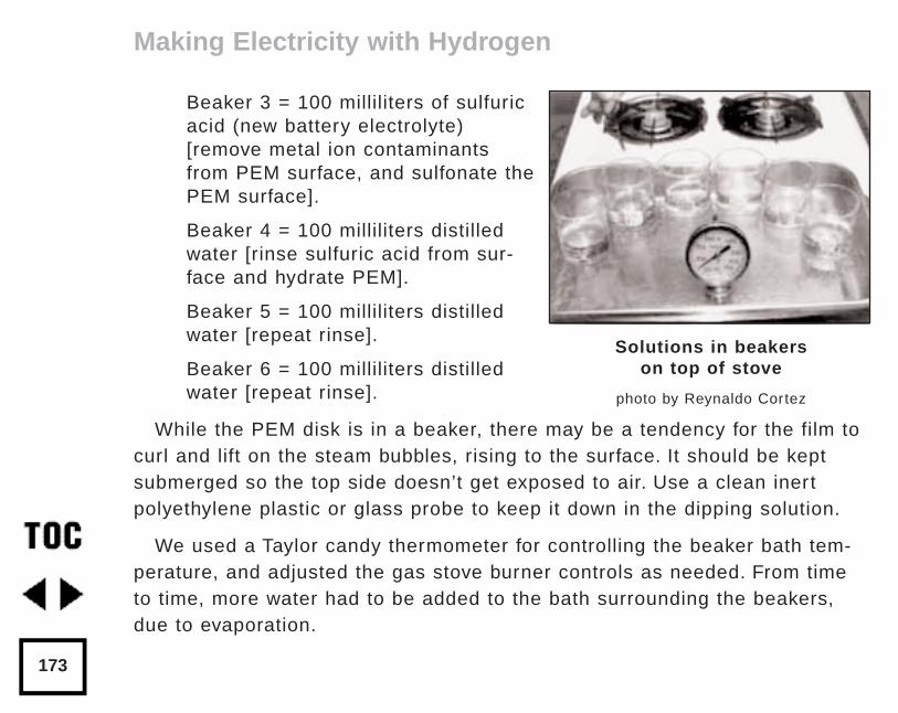
Beaker 3 = 100 milliliters of sulfuricacid (new battery electrolyte)[remove metal ion contaminantsfrom PEM surface, and sulfonate thePEM surface].
Beaker 4 = 100 milliliters distilledwater [rinse sulfuric acid from sur-face and hydrate PEM].
Beaker 5 = 100 milliliters distilledwater [repeat rinse].
Beaker 6 = 100 milliliters distilledwater [repeat rinse].
While the PEM disk is in a beaker, there may be a tendency for the film tocurl and lift on the steam bubbles, rising to the surface. It should be keptsubmerged so the top side doesn’t get exposed to air. Use a clean inertpolyethylene plastic or glass probe to keep it down in the dipping solution.
We used a Taylor candy thermometer for controlling the beaker bath tem-perature, and adjusted the gas stove burner controls as needed. From timeto time, more water had to be added to the bath surrounding the beakers,due to evaporation.
Making Electricity with Hydrogen
173
Solutions in beakers on top of stove
photo by Reynaldo Cortez
After the PEM disk was dipped in each of the six hot solution beakers foran hour, it was then wiped with a piece of lint-free lens cleaning tissue, andair-dried in a clean place.
The Catalyst Layer Material
The catalyst layer is the most expensive part of this fuel cell. It is madefrom a mixture of platinum, carbon powder, and PEM powder, bonded to aconductive carbon fiber cloth. We obtained ours from E-Tek Inc. The cost foran order of their ELAT catalyst cloth sheet includes a setup charge. So gettogether with others for a larger order if you want to keep costs down. Wepaid $360 for a piece of ELAT 15.2 centimeters by 15.2 centimeters [6” by6”] including the $150 setup charge. This piece provides enough for abouttwelve disks. Each fuel cell requires two disks of ELAT and one larger diskof PEM to make the sandwich, so you can make six cells from this sizepiece of ELAT ($60/cell). The cost may have come down by now due toincreased production at E-Tek. In the future it may be possible to reduce thecost by putting the catalyst coating directly on the PEM with a platinum-car-bon ink, as practiced by Los Alamos National Laboratory.
Making Electricity with Hydrogen
174
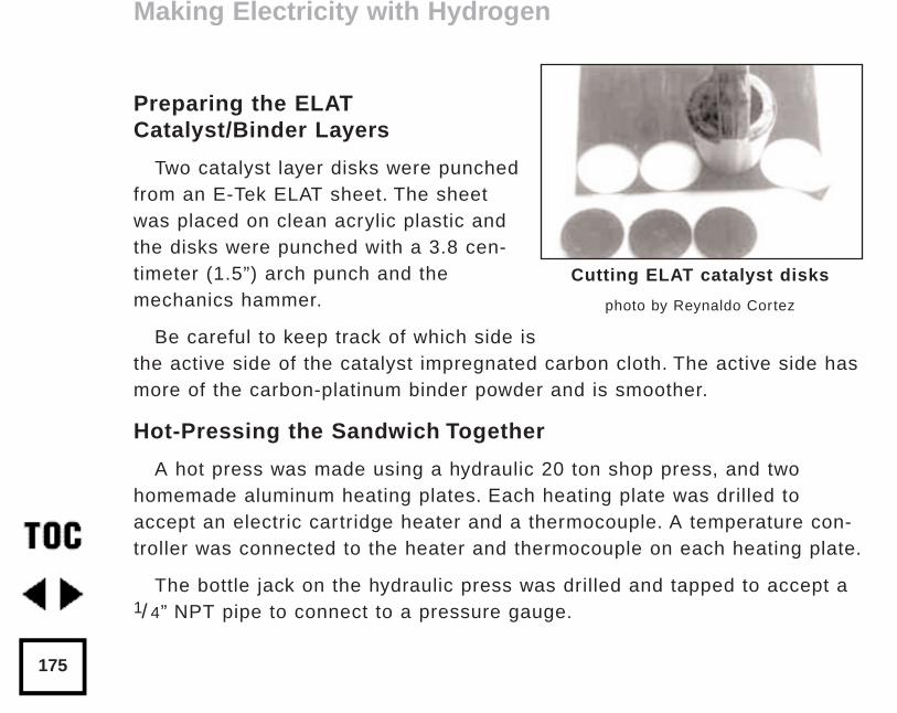
Preparing the ELATCatalyst/Binder Layers
Two catalyst layer disks were punchedfrom an E-Tek ELAT sheet. The sheetwas placed on clean acrylic plastic andthe disks were punched with a 3.8 cen-timeter (1.5”) arch punch and the mechanics hammer.
Be careful to keep track of which side isthe active side of the catalyst impregnated carbon cloth. The active side hasmore of the carbon-platinum binder powder and is smoother.
Hot-Pressing the Sandwich Together
A hot press was made using a hydraulic 20 ton shop press, and twohomemade aluminum heating plates. Each heating plate was drilled toaccept an electric cartridge heater and a thermocouple. A temperature con-troller was connected to the heater and thermocouple on each heating plate.
The bottle jack on the hydraulic press was drilled and tapped to accept a1/ 4” NPT pipe to connect to a pressure gauge.
Making Electricity with Hydrogen
175
Cutting ELAT catalyst disks
photo by Reynaldo Cortez
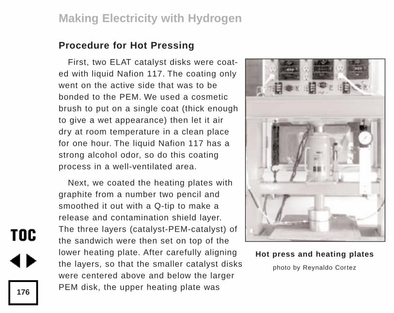
Procedure for Hot Pressing
First, two ELAT catalyst disks were coat-ed with liquid Nafion 117. The coating onlywent on the active side that was to bebonded to the PEM. We used a cosmeticbrush to put on a single coat (thick enoughto give a wet appearance) then let it airdry at room temperature in a clean placefor one hour. The liquid Nafion 117 has astrong alcohol odor, so do this coatingprocess in a well-ventilated area.
Next, we coated the heating plates withgraphite from a number two pencil andsmoothed it out with a Q-tip to make arelease and contamination shield layer.The three layers (catalyst-PEM-catalyst) ofthe sandwich were then set on top of thelower heating plate. After carefully aligningthe layers, so that the smaller catalyst diskswere centered above and below the largerPEM disk, the upper heating plate was
Making Electricity with Hydrogen
176
Hot press and heating plates
photo by Reynaldo Cortez
placed on top of the sandwich. At this time the heaters were off and the plateswere at room temperature.
Next, the two temperature controllers were activated and the sandwich wastaken up to 90°C (194°F) for one hour to evaporate the solvents from the liquidNafion 117 catalyst coating. The temperature was then raised to 130°C (266°F)over the next 30 minutes. This is the PEM glass transition temperature.
Once the heating plates and the sandwich reached 130°C, pressure wasapplied using the hydraulic jack, up to 2.16 MPa (300 psig). Shortly thereafter,the pressure fell off as the PEM was squeezed by the heated plates and thesandwich became thinner.
After two minutes at temperature and pressure, the temperature controllerswere turned off and the plates and sandwich cooled to room temperature.
The heater plates were opened, and the finished fuel cell sandwich wasremoved using the special tweezers. We noted that the PEM disk was no longer round, but instead somewhat elliptical. This may be due to alignment ofthe film molecules in one preferential direction. The fuel cell sandwich did notstick to the aluminum heater plates, so the graphite release coating appearedto be effective.
Making Electricity with Hydrogen
177
Fuel Cell Test Fixture
Our fuel cell test fixture was made from a commercially available mem-brane filter holder. We spot-welded electrode studs to the two halves of thefixture case, one for the hydrogen side and one for the oxygen (air) side. Agroove for an o-ring was machined into each half of the case, to provide aseal to prevent the gases from leaking around the edges of the gas distribution plates.
Kapton tape was applied to the inside diameter of one case to insulate itfrom the other. Kapton tape was also applied to the outer diameter of themating case to insulate the retaining ring and prevent the two cases fromshorting together. An ohm-meter was used to assure that the two caseswere well-insulated from one another.
The PEM sandwich was trimmed with a pair of scissors until it was roundagain, and placed between the filter holder’s two stainless steel gas distri-bution plates to make a five layered sandwich. The five-layered sandwichwas then dropped into the Kapton lined case and the other case (with theKapton on the outside) was applied on top and attached by the threadedretainer ring.
Making Electricity with Hydrogen
178
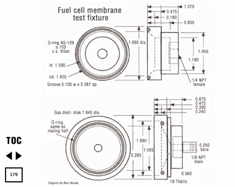
179
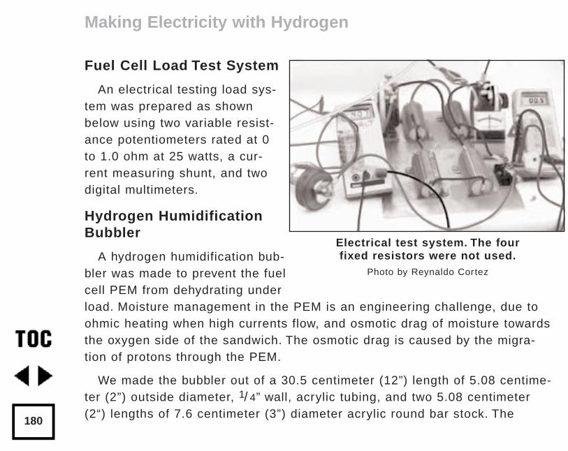
Fuel Cell Load Test System
An electrical testing load sys-tem was prepared as shownbelow using two variable resist-ance potentiometers rated at 0to 1.0 ohm at 25 watts, a cur-rent measuring shunt, and twodigital multimeters.
Hydrogen HumidificationBubbler
A hydrogen humidification bub-bler was made to prevent the fuelcell PEM from dehydrating underload. Moisture management in the PEM is an engineering challenge, due toohmic heating when high currents flow, and osmotic drag of moisture towardsthe oxygen side of the sandwich. The osmotic drag is caused by the migra-tion of protons through the PEM.
We made the bubbler out of a 30.5 centimeter (12”) length of 5.08 centime-ter (2”) outside diameter, 1/ 4” wall, acrylic tubing, and two 5.08 centimeter(2“) lengths of 7.6 centimeter (3”) diameter acrylic round bar stock. The
Making Electricity with Hydrogen
180
Electrical test system. The fourfixed resistors were not used.
Photo by Reynaldo Cortez
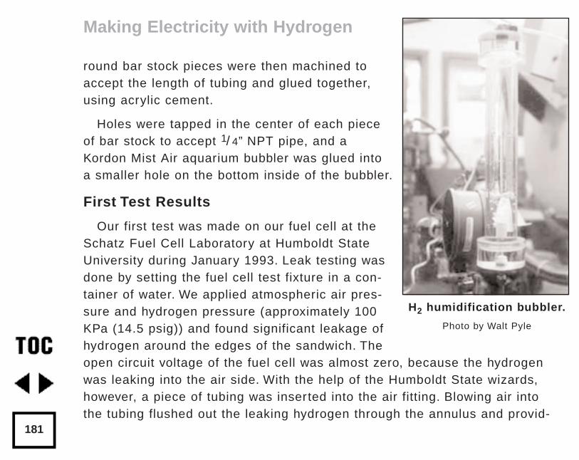
round bar stock pieces were then machined toaccept the length of tubing and glued together,using acrylic cement.
Holes were tapped in the center of each pieceof bar stock to accept 1/ 4” NPT pipe, and aKordon Mist Air aquarium bubbler was glued intoa smaller hole on the bottom inside of the bubbler.
First Test Results
Our first test was made on our fuel cell at theSchatz Fuel Cell Laboratory at Humboldt StateUniversity during January 1993. Leak testing wasdone by setting the fuel cell test fixture in a con-tainer of water. We applied atmospheric air pres-sure and hydrogen pressure (approximately 100KPa (14.5 psig)) and found significant leakage ofhydrogen around the edges of the sandwich. Theopen circuit voltage of the fuel cell was almost zero, because the hydrogenwas leaking into the air side. With the help of the Humboldt State wizards,however, a piece of tubing was inserted into the air fitting. Blowing air intothe tubing flushed out the leaking hydrogen through the annulus and provid-
Making Electricity with Hydrogen
181
H2 humidification bubbler.
Photo by Walt Pyle
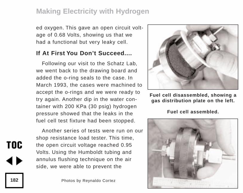
ed oxygen. This gave an open circuit volt-age of 0.68 Volts, showing us that wehad a functional but very leaky cell.
If At First You Don’t Succeed....
Following our visit to the Schatz Lab,we went back to the drawing board andadded the o-ring seals to the case. InMarch 1993, the cases were machined toaccept the o-rings and we were ready totry again. Another dip in the water con-tainer with 200 KPa (30 psig) hydrogenpressure showed that the leaks in thefuel cell test fixture had been stopped.
Another series of tests were run on ourshop resistance load tester. This time,the open circuit voltage reached 0.95Volts. Using the Humboldt tubing andannulus flushing technique on the airside, we were able to prevent the
Making Electricity with Hydrogen
182
Fuel cell disassembled, showing agas distribution plate on the left.
Fuel cell assembled.
Photos by Reynaldo Cortez
nitrogen gas from concentrating inside the cell (as the oxygen was con-sumed from the air). We obtained a short circuit current of over 1.5 Amperesfor short periods of time (minutes). And then, by varying the load resistancewe obtained data at different operating voltages and currents for the cell.Sustained power output was limited, we think, by poor moisture control onthe cathode (too dry) or anode (too wet). A graph of the current-voltageresponse of the cell is shown above.
Future Direction
This saga has only just begun, and we are learning some valuable les-sons as we go. Water management on both sides of the cell is a major chal-lenge. On the hydrogen side, the PEM must be kept damp so it won’t crack,and short or leak. On the oxygen side, water is produced which must beremoved so the ELAT catalyst won’t “drown” and get starved for oxygen.
We plan to try some experiments with oxygen instead of air on the anodeside. Wick-like materials will be tried for passively absorbing and transport-ing water to the PEM and transporting water from the ELAT anode catalyst.
Ultimately, we’d like to have a 12 Volt or 24 Volt fuel cell that could beused in the home to power a 2 kW inverter for supplying 120 Volts, 50/60 Hzalternating current. Batteries would be eliminated, and solar energy wouldbe stored as hydrogen and oxygen in tanks until it was needed. Others are
Making Electricity with Hydrogen
183
dreaming of PEMFC cars, and locomotives. As we go to press, BallardBattery Co. in Vancouver B.C. is driving a fuel cell powered bus around theparking lot!
Please let us hear from you if you have any suggestions for improve-ments or new experience to share. We don’t want to squirrel this technolo-gy away; we’d rather set it free!
Hydrogen Safety Considerations
For a more thorough discussion of the safety consciousness one shoulddevelop when working with hydrogen, see the chapter “Heatin’ withHydrogen” (p.142). The bottom line is:
• Work with hydrogen out of doors or in a well-ventilated area.
• Store only pure hydrogen or oxygen, never mixtures of gases.
• Remember the explosive mixture limits are wide and different fromother fuels: even very rich hydrogen-air or hydrogen-oxygen mixturescan burn violently.
AccessAuthors:
Walt Pyle, WA6DUR, Richmond, CA • 510- 237-7877
Alan Spivak, KC6JZN, Berkeley, CA • 510-525-4082
Making Electricity with Hydrogen
184
Reynaldo Cortez, Richmond, CA • 510-237-9748
Jim Healy, WH6LZ, Richmond, CA • 510-236-6745
ReferenceU.S. Patent No. 4,661,411, Method For Depositing AFluorocarbonsulfonic Acid Polymer From A Solution, April 28, 1987;Inventors: C.W. Martin, B.R. Ezzell, J.D. Weaver; Assigned to DowChemical Co., Midland, MI
Acknowledgements for Articles and DiscussionsSupramaniam Srinivasan, A.C. Ferreira, Imran J. Kakwan, David Swan;Texas A&M University, College Station, TX
Roger Billings, Maria Sanchez; International Academy of Science,Independence, MO
Peter Fowler, E-Tek Inc., Framingham, MA
Peter Lehman, Tom Herron, Ron Reid; CA State University atHumboldt,
Schatz Fuel Cell Laboratory, Arcata, CA
David Booth, Alternative Energy Engineering, Redway, CA
PEM MaterialsNafion 117 PEM (du Pont) 0.007 inch thickness:
Aldrich Chemical Co., Catalog No 29,256-7
Making Electricity with Hydrogen
185

PEM Materials (continued)Nafion 117 solution (Nafion perfluorinated ion-exchange powder 5%mixture of lower aliphatic alcohols and 10% water d 0.874):
Aldrich Chemical Co., Catalog No. 27,470-4 • 800-558-9160
Nafion 117 PEM (orders greater than 0.61 m by 0.61 m [24 inches by24 inches] or larger):
I.E. du Pont de Nemours & Co., Customer Service Dept. • 302-695-5249
Catalyst/Binder MaterialsELAT Solid Polymer Electrolyte Electrode 20% Pt/C with 0.4 mg/cm 2Pt loading: E-Tek, Inc., 1 Mountain Rd, Framingham Industrial Park,Framingham, MA 01701 • 508-879-0733
Test FixtureStainless Steel In-line Filter Holder: Catalog No. L-02929-20 (47 mm),Cole-Parmer Instrument Co., 7425 N. Oak Park Ave., Chicago, IL60648 • 800-323-4340
Hot Press Components20 Ton Hydraulic Press: Post Tool Co. 800 E. 8th Street Oakland, CA •510-272-0331
Temperature Controllers, Thermocouples, Cartridge Heaters: OmegaEngineering Inc., 1 Omega Dr., Stamford CT 0690 • 203-359-1660
Making Electricity with Hydrogen
186
by Clifford W. MossbergOriginally published in Home Power #21 • February / March 1991©1991 Clifford W. Mossberg
For most of us who live in secluded areas and who employ alternativeenergy technologies to provide us with a contemporary standard of living,looking for more efficient alternatives is second nature. Most of us havewondered about an alternative to the use of fossil-fueled engine/generatorsto back up our more desirable energy sources.
Photovoltaics and wind energy are intermittent or diffuse technologieswhich require storage to be effective and are limited in output. Hydro poweris site specific and will not be available in many places. Alternative energygeneration also costs a lot of money initially and the temptation to go withthe cheapest and sometimes only affordable power source is strong. Usuallythat is a fuel driven engine/generator. There are lots of reasons to use a"light plant,” but sooner or later the moment of truth comes: These things arenoxious, noisy, take more maintenance than a new born baby, and eat morethan a teenager. "Isn't there something else!?"
Yes there is. The advantage to a "light plant" is that by paying the pricewe are able to create energy in large quantities and at our discretion usingeasily obtainable and conveniently transported fuel. We are not at the whimof wind, sun and water. So any replacement technology must have, at a min-imum, this element of discretionary use.
Alternatives to Fossil Fueled Engine/Generators
187
Steam Power
Historically one of the earliest alternatives to fossil fuels is a wood firedboiler producing steam which powers an engine driving a generator. I'venoticed interest in this recently among letters from Home Power readers. Iwould like to share some perspectives on steam power and its alternatives.
First the good news: Steam can be produced from wood; allowing us touse Ma Nature to produce and store our energy for us in our own back forty.This, unfortunately is about the only advantage. The bad news is that steampower has all the disadvantages of an engine/generator and several more allits own. Ma Nature may provide the fuel but we, the user, must "condition" it.The wood must be chopped and carried, cured, split, and fed, just as for anywood stove. Ashes must be handled and hauled. The entire installationrequires constant babysitting while it is running - no walking away from thisthing to do the wash! But the real kicker is the inherent danger in steam.
Steam occupies about 1200 times the volume of water at atmosphericpressure (known as "gage" pressure) - that's one thousand two hundredtimes! Producing steam requires heating water to above boiling temperatureunder pressure. Water boils at 212° F. at sea level. By pressurizing the boil-er it is possible to raise the boiling temperature of water much higher. At apressure of 52 psi gage the boiling temperature is 300°, at 120 psi gage it is350°. Elevating steam temperature like this HAS to be done to use the the
Alternatives to Fossil Fueled Engine/Generators
188
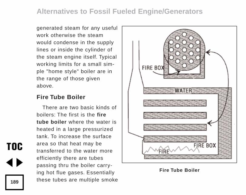
generated steam for any usefulwork otherwise the steamwould condense in the supplylines or inside the cylinder ofthe steam engine itself. Typicalworking limits for a small sim-ple "home style" boiler are inthe range of those givenabove.
Fire Tube Boiler
There are two basic kinds ofboilers: The first is the firetube boiler where the water isheated in a large pressurizedtank. To increase the surfacearea so that heat may betransferred to the water moreefficiently there are tubespassing thru the boiler carry-ing hot flue gases. Essentiallythese tubes are multiple smoke
Alternatives to Fossil Fueled Engine/Generators
189
Fire Tube Boiler
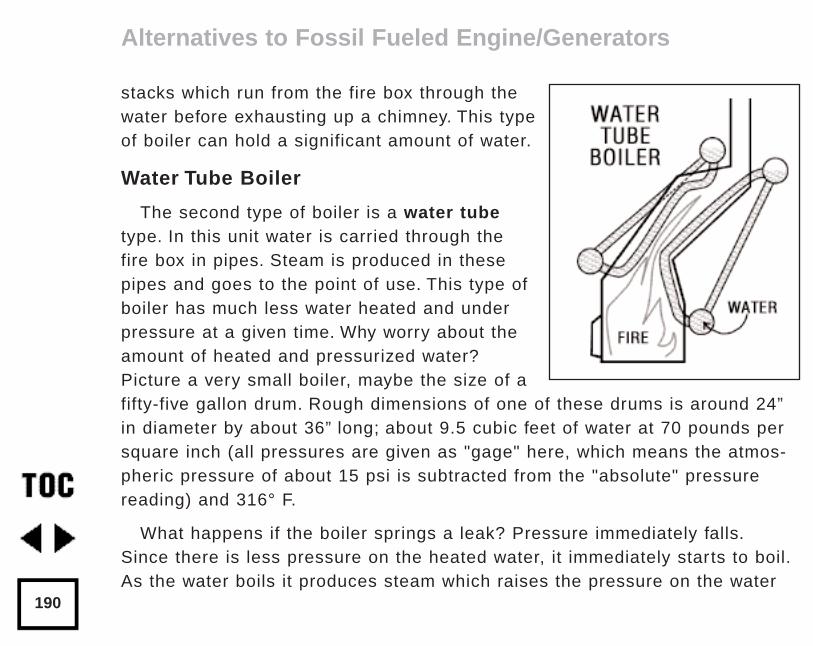
stacks which run from the fire box through thewater before exhausting up a chimney. This typeof boiler can hold a significant amount of water.
Water Tube Boiler
The second type of boiler is a water tubetype. In this unit water is carried through thefire box in pipes. Steam is produced in thesepipes and goes to the point of use. This type ofboiler has much less water heated and underpressure at a given time. Why worry about theamount of heated and pressurized water?Picture a very small boiler, maybe the size of afifty-five gallon drum. Rough dimensions of one of these drums is around 24”in diameter by about 36” long; about 9.5 cubic feet of water at 70 pounds persquare inch (all pressures are given as "gage" here, which means the atmos-pheric pressure of about 15 psi is subtracted from the "absolute" pressurereading) and 316° F.
What happens if the boiler springs a leak? Pressure immediately falls.Since there is less pressure on the heated water, it immediately starts to boil.As the water boils it produces steam which raises the pressure on the water
Alternatives to Fossil Fueled Engine/Generators
190
and inhibits boiling. This condition normally exists in a boiler and produces acontrolled reaction. The "leak" is the boiler steam outlet pipe.
But what happens if there is an uncontrolled leak in the boiler such asequipment failure might produce? As pressure drops and water starts to boilthere is no restriction to stabilize the pressure and all the water can imme-diately flash into steam. In our example if you start out with 91/ 2 cubic feetof superheated water and reduce the pressure to zero you almost instanta-neously have 1200 times 91/ 2 cubic feet, equal in volume to a single storyhouse measuring about 35 by 40 feet. You suddenly have 11,400 cubic feetof steam in a 91/ 2 cubic foot pot and a real - but short lived - problem; amassive boiler explosion.
At the core of this explosion is superheated steam at 316°. If the shrapneland concussion is daunting enough, this 316° steam will instantly cook anyflesh it comes in contact with and can literally strip flesh off the bone. Doesthe average small homesteader want to play dice with this process? (Thehypothetical boiler in our example has a total internal working force of about125 tons applied to it!)
A water tube boiler is more benign. It may only result in an explosivesteam volume of one or two "rooms" in the "house" in the example.Therefore a water tube boiler is the preferred design for anyone getting
Alternatives to Fossil Fueled Engine/Generators
191
serious about steam. Failure of a water tube boiler probably won't take outCity Hall, but it would not be comforting to those in the vicinity.
So why not just opt for a water tube boiler and get on with it? Economics.A fire tube boiler can be fabricated from a cylindrical tank with straighttubes running through it from end to end. A water tube boiler is fabricatedas a fire box with many small tubes with complicated bends in them weldedinside. There is a lot more precise design, welding, and fabrication involvedwith a water tube boiler.
Then there is the fact that all boilers manufactured or used in the UnitedStates must be built to rigid specifications and tested in accordance withregulation and prescribed procedure; not just initially but throughout theirinstalled life. Any boiler is potentially dangerous and expensive.
If you are willing to spend money to acquire a working boiler and operateit what do you have? Let's look at efficiency:
The traditional gasoline engine can be used as a baseline that we arefamiliar with. It is considered to be about 28% efficient. A diesel engine isconsidered to be about 32% efficient. This efficiency is a measure of theengine's ability to turn heat energy in fuel into useful work and the figuresI've given represent an average of a range of values. A better way of think-ing of efficiency is that 72% of the heat developed by gasoline burned in a
Alternatives to Fossil Fueled Engine/Generators
192
gasoline engine is wasted; or about seven out of every ten gallons of gasyou burn goes to heat the air, either through the radiator, radiation from theengine, or out the tailpipe. How does steam compare?
A typical single acting single cylinder steam engine (the kind most of usmight easily acquire) runs from about 7% to 12% efficiency. A high perform-ance double acting multi-cylinder unit might run about 15% to 17% efficien-cy. A well insulated unit with a vacuum condenser might push that up as highas 22% if you were very lucky. Even were you to go to a very sophisticatedsteam turbine installation - totally out of sight financially for most of us - theefficiency would only be pushed up to about 26%; the lower end of gasolineengine technology. Bear in mind that you will bear the direct burden of thisinefficiency right on your back. Only 7% of the energy in the firewood youpainstakingly lugged out of the woodlot will turn into energy you can use togenerate electricity. This doesn't factor in any environmental damage.
I haven't said anything yet about your time. The typical small steam instal-lation will require constant attention to operate. Automatic controls do notadapt well to burning a non-uniform fuel like logwood and are too expensiveand complex to find their way into small installations. You will have to hoverover this unit to feed fuel, monitor boiler pressure, check feed water, oilequipment, etc. The operator is apt to become the exclusive servant of themachine when it is powered up.
Alternatives to Fossil Fueled Engine/Generators
193
Now that I have painted this bleak picture let's ask if there's any alterna-tive to steam as a replacement for the family "light plant"? Yes! The surpris-ing answer is that a conventional gasoline or diesel driven engine/generatorset can be combined with wood gas technology to do the job. While it hasdrawbacks of its own, this marriage is much cheaper and safer than steam.
Wood Gasification Basics
Wood gasification is also called producer gas generation and destructivedistillation. The essence of the process is the production of flammable gasproducts from the heating of wood. Carbon monoxide, methyl gas, methane,hydrogen, hydrocarbon gases, and other assorted components, in differentproportions, can be obtained by heating or burning wood products in an iso-lated or oxygen poor environment. This is done by burning wood in a burnerwhich restricts combustion air intake so that the complete burning of the fuelcannot occur. A related process is the heating of wood in a closed vesselusing an outside heat source. Each process produces different products.
If wood were given all the oxygen it needs to burn cleanly the by-productsof the combustion would be carbon dioxide, water, some small amount ofash, (to account for the inorganic components of wood) and heat. This is thetype of burning we strive for in wood stoves.
Alternatives to Fossil Fueled Engine/Generators
194
Once burning begins, though, it is possible to restrict the air to the fueland still have the combustion process continue. Lack of sufficient oxygencaused by restricted combustion air will cause partial combustion. In fullcombustion of a hydrocarbon (wood is basically a hydrocarbon) oxygen willcombine with the carbon in the ratio of two atoms to each carbon atom. Itcombines with the hydrogen in the ratio of two atoms of hydrogen to one ofoxygen. This produces CO2 (carbon dioxide) and H2O (water). Restrict theair to combustion and the heat will still allow combustion to continue, butimperfectly. In this restricted combustion, one atom of oxygen will combinewith one atom of carbon, while the hydrogen will sometimes combine withoxygen and sometimes not combine with anything. This produces carbonmonoxide, (CO) (the same gas as car exhaust and for the same reason)water (H2O), and hydrogen gas (H). It will also produce a lot of other com-pounds and elements such as carbon, (C) which is smoke.
Combustion of wood is a bootstrap process. The heat from combustionbreaks down the chemical bonds between the complex hydrocarbons foundin wood (or any other hydrocarbon fuel) while the combination of the result-ant carbon and hydrogen with oxygen - combustion - produces the heat.Thus the process drives itself. If the air is restricted to combustion, theprocess will still produce enough heat to break down the the wood, but theproducts of this inhibited combustion will be carbon monoxide and hydrogen,
Alternatives to Fossil Fueled Engine/Generators
195
fuel gases which have the potential to continue the combustion reaction andrelease heat since they are not completely burned yet. (The other productsof incomplete combustion, predominately carbon dioxide and water, areproducts of complete combustion and can be carried no further.) Thus it is asimple technological step to produce a gaseous fuel from solid wood. Wherewood is bulky to handle, a fuel like wood gas (producer gas) is convenientand can be burned in various existing devices, not the least of which is theinternal combustion engine. A properly designed burner combining wood andair is one relatively safe way of doing this.
Crude Wood Gas Generator
Another path to a similar result is to heat wood in a closed container untilit is hot enough for the chemical bonds holding the hydrogen and carbontogether to break. This is destructive distillation, a quite different processfrom that of combustion since no outside oxygen is introduced. You mightthink that such a device would produce only hydrogen gas and carbon. Butthat is only because I have kept this explanation oversimplified for clarity.The products of this process will depend on the make up of the wood andthe temperature it is heated to. All wood contains some water and this canbe anywhere from about 7% to 50% or higher, so this water is available toplay a part in the destructive distillation process. Wood also contains many
Alternatives to Fossil Fueled Engine/Generators
196
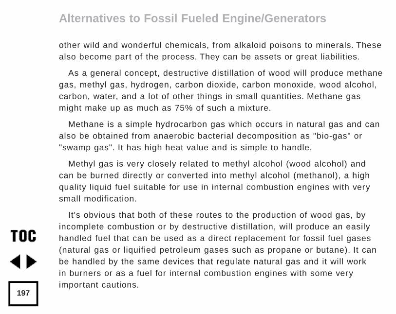
other wild and wonderful chemicals, from alkaloid poisons to minerals. Thesealso become part of the process. They can be assets or great liabilities.
As a general concept, destructive distillation of wood will produce methanegas, methyl gas, hydrogen, carbon dioxide, carbon monoxide, wood alcohol,carbon, water, and a lot of other things in small quantities. Methane gasmight make up as much as 75% of such a mixture.
Methane is a simple hydrocarbon gas which occurs in natural gas and canalso be obtained from anaerobic bacterial decomposition as "bio-gas" or"swamp gas". It has high heat value and is simple to handle.
Methyl gas is very closely related to methyl alcohol (wood alcohol) andcan be burned directly or converted into methyl alcohol (methanol), a highquality liquid fuel suitable for use in internal combustion engines with verysmall modification.
It's obvious that both of these routes to the production of wood gas, byincomplete combustion or by destructive distillation, will produce an easilyhandled fuel that can be used as a direct replacement for fossil fuel gases(natural gas or liquified petroleum gases such as propane or butane). It canbe handled by the same devices that regulate natural gas and it will workin burners or as a fuel for internal combustion engines with some veryimportant cautions.
Alternatives to Fossil Fueled Engine/Generators
197
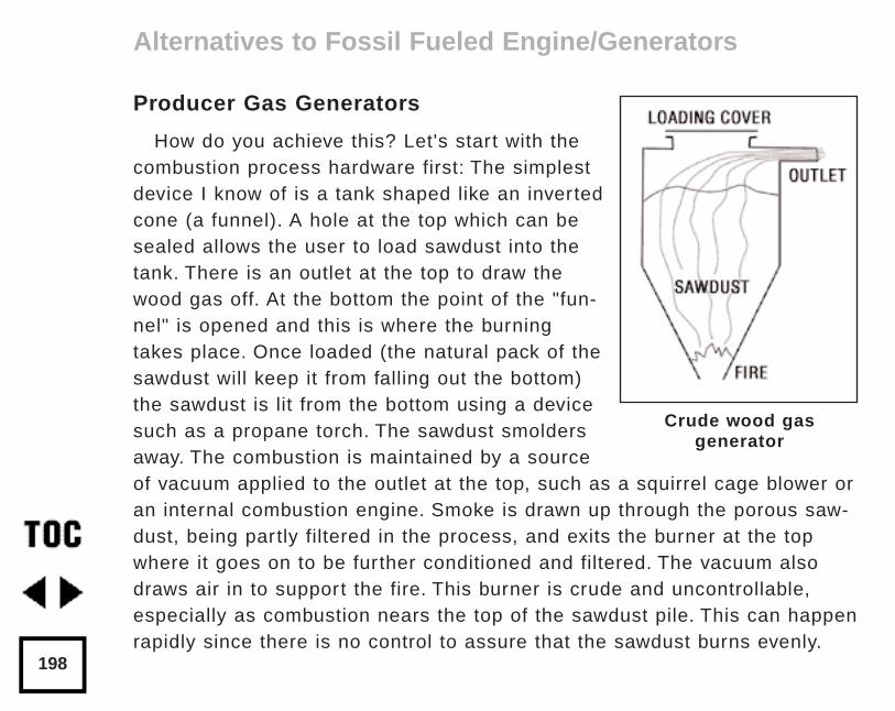
Producer Gas Generators
How do you achieve this? Let's start with thecombustion process hardware first: The simplestdevice I know of is a tank shaped like an invertedcone (a funnel). A hole at the top which can besealed allows the user to load sawdust into thetank. There is an outlet at the top to draw thewood gas off. At the bottom the point of the "fun-nel" is opened and this is where the burningtakes place. Once loaded (the natural pack of thesawdust will keep it from falling out the bottom)the sawdust is lit from the bottom using a devicesuch as a propane torch. The sawdust smoldersaway. The combustion is maintained by a sourceof vacuum applied to the outlet at the top, such as a squirrel cage blower oran internal combustion engine. Smoke is drawn up through the porous saw-dust, being partly filtered in the process, and exits the burner at the topwhere it goes on to be further conditioned and filtered. The vacuum alsodraws air in to support the fire. This burner is crude and uncontrollable,especially as combustion nears the top of the sawdust pile. This can happenrapidly since there is no control to assure that the sawdust burns evenly.
Alternatives to Fossil Fueled Engine/Generators
198
Crude wood gasgenerator
"Leads" of fire can form in the sawdust reaching toward the top surface.Once the fire breaks through the top of the sawdust, the vacuum applied tothe burner will pull large amounts of air in supporting full combustion andleaning out the value of the producer gas as a fuel. This process dependson the poor porosity of the sawdust to control the combustion air, so chunkwood cannot be used since its much greater porosity would allow too muchair in, and you would achieve full combustion at very high temperaturesrather than the smouldering and the the partial combustion you want. Such aburner is unsatisfactory for prolonged gas generation but it is cheap to buildand it will work with a lot of fiddling.
For prolonged trouble-free operation of a wood gas generator, the burnerunit must have more complete control of the combustion air and the fuelfeed. There are various ways to do this. For example, if the point of our orig-inal funnel shaped burner is completely enclosed, then control over the airentering the burner can be achieved. This configuration will successfullyburn much larger pieces of wood. One of the most widely known burnerswas developed by Mother Earth News magazine. They produced a completeset of plans for their burner and featured its construction and evaluation inseveral issues of their magazine. At the end of this article I have listedsources of information and/or hardware for several of the concepts I havewritten about.
Alternatives to Fossil Fueled Engine/Generators
199
Destructive Distillation Units
If the type of wood gas you would like to produce is to be obtained bydestructive distillation then all you need is a canister about the size of a 55gallon drum that can be loaded with wood and sealed air tight. It must alsohave an outlet pipe and a source of heat which can be applied to it from theoutside. A simple way to do this would be to just build a wood bonfire underthe canister. While this has the advantage of being "quick and dir ty," it is theequivalent of the simple sawdust burner I described above. It allows littlecontrol and requires a lot of time and fussing to make anything work.
The use of a fossil fuel to heat the wood gives good control over the tem-perature of distillation but defeats the purpose of producing a fuel fromwood. An ideal solution to this control problem is to use a combustion typewood gas generator to produce fuel gas, which is then burned to achievedestructive distillation, which produces a higher heat content fuel; a fuel thatcan then be liquified into methanol.
It is also desirable to mount the canister in such a way that it can be rotat-ed while it is being heated so that the contents inside are evenly "cooked".
Conditioning And Filtration
However you produce the wood gas, you are certainly not home free whenyour fuel exits your burner. Far from being the nice clean chemical reactions
Alternatives to Fossil Fueled Engine/Generators
200
I've used for simplicity, the fuel gas you will actually produce will containash, gum, heat, water, creosote, acids, and a lot of other weird things whichwill render any device you try to burn the fuel in dead on arrival. The fuelmust be conditioned and filtered before it can be used.
Probably the best first step to achieve gas conditioning is a cyclone sepa-rator to get rid of water and particulate matter. This device is, again, aninverted cone, but the bottom is sealed. After the contaminated fuel gasleaves the burner unit, it enters the top on a tangent to the circumference ofthe side. The exit for the fuel is a pipe which runs up the center of this conefrom just above the point at the bottom. Gas coming into the cyclone sepa-rator enters with some velocity. Because it has weight, and therefore inertia,it tries to continue in a straight line, even though the sides of the cone arecurved. To exit the cone, the gas would have to turn 90° toward the bottomand then 180° up the exit pipe, if it could take the shortest path. However,under the influence of its own inertia, the dir ty fuel gas is held against thecurved outside wall of the cone, where it takes a circular path toward thebottom and the exit pipe. It circles around and around this wall, all the timemoving in tighter and tighter circles toward the point on the bottom, thusspeeding up its velocity as the circles get smaller nearer the point. The fuelgas is spinning quite fast near the exit pipe. This rotary gas flow is wherethe separator gets its name.
Alternatives to Fossil Fueled Engine/Generators
201
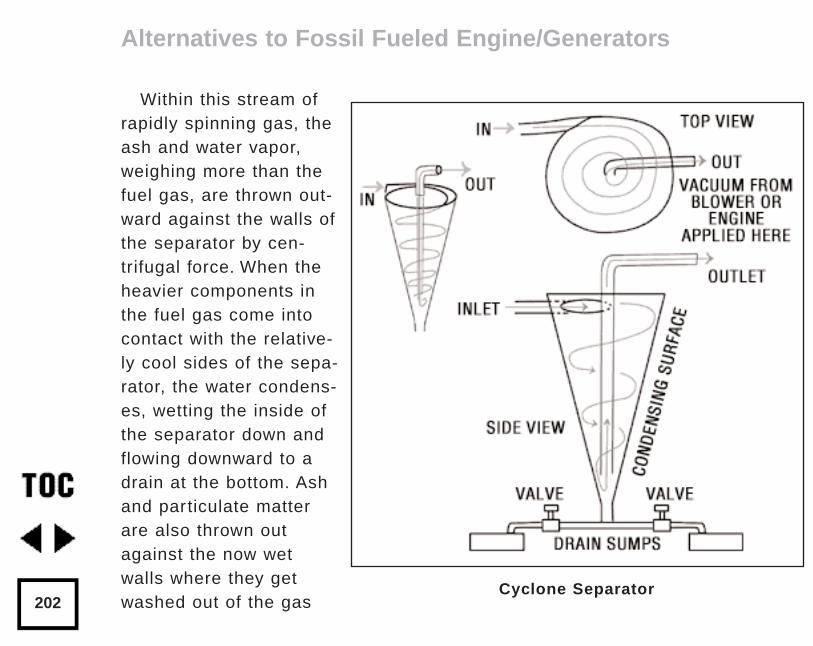
Within this stream ofrapidly spinning gas, theash and water vapor,weighing more than thefuel gas, are thrown out-ward against the walls ofthe separator by cen-trifugal force. When theheavier components inthe fuel gas come intocontact with the relative-ly cool sides of the sepa-rator, the water condens-es, wetting the inside ofthe separator down andflowing downward to adrain at the bottom. Ashand particulate matterare also thrown outagainst the now wetwalls where they getwashed out of the gas
Alternatives to Fossil Fueled Engine/Generators
202Cyclone Separator
stream by the condensing liquid. All of this gunk winds up running out the bottom of the separator and into a holding tank, which can be drainedat intervals.
To help the water condense out of the gas stream, the walls of the cycloneseparator may be cooled by water or an air stream to raise the efficiency ofthe condensation and scrubbing process.
Upon its exit from the cyclone separator, the fuel gas will have to becooled further. A simple way to do this is to place a vehicle radiator into thegas flow and draw the fuel gas through this. In a perfect world there wouldn'tbe any water left in the fuel gas after it left the cyclone separator.Unfortunately, there is apt to be quite a bit of uncondensed water vapor stillleft in the hot fuel gas as it enters the gas cooler. As the gas cools, the watervapor will condense out further. It may be necessary to use multiple stagesto completely cool the fuel gas. That is, you may have to use more than oneradiator, with the outlet of one connected to the inlet of the next, and so on.Cooling air can be blown through each radiator by an electric cooling fan andeach radiator will need a sealed drain canister to carry off condensed liquid.
Once the cool dry fuel gas leaves the cooler, it is ready for the last stageof conditioning. It must be well filtered to keep fine ash and particulate mat-ter from being carried into the engine or burner which the gas will be used in.
Alternatives to Fossil Fueled Engine/Generators
203
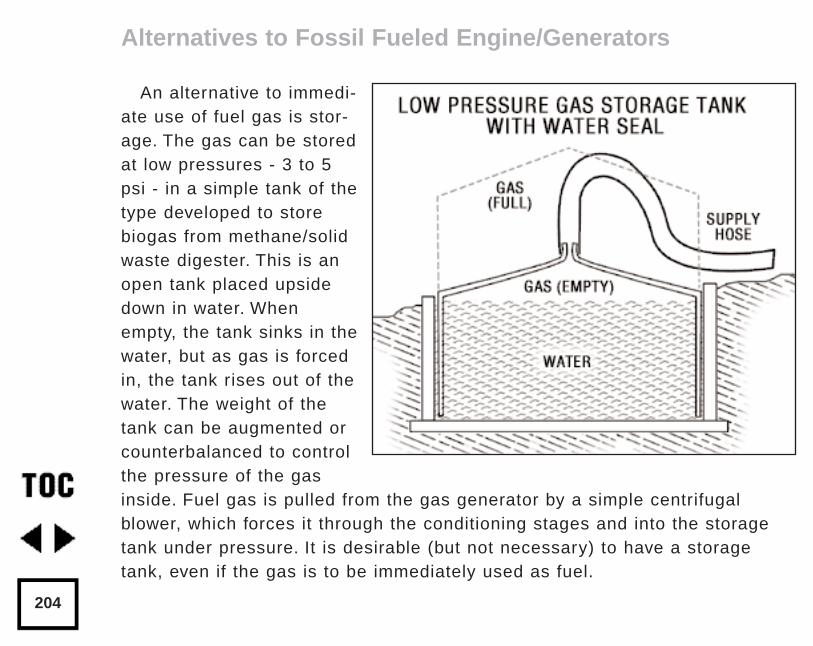
An alternative to immedi-ate use of fuel gas is stor-age. The gas can be storedat low pressures - 3 to 5psi - in a simple tank of thetype developed to storebiogas from methane/solidwaste digester. This is anopen tank placed upsidedown in water. Whenempty, the tank sinks in thewater, but as gas is forcedin, the tank rises out of thewater. The weight of thetank can be augmented orcounterbalanced to controlthe pressure of the gasinside. Fuel gas is pulled from the gas generator by a simple centrifugalblower, which forces it through the conditioning stages and into the storagetank under pressure. It is desirable (but not necessary) to have a storagetank, even if the gas is to be immediately used as fuel.
Alternatives to Fossil Fueled Engine/Generators
204
Such a reservoir maintains a buffer supply of gas to even out any fluctua-tions in supply and provides an even, controllable supply of pressure to theend device. It also acts as a cooler and a sink for any impurities whichremain in the fuel gas after conditioning. Such a storage tank could pay foritself by saving money on conditioning the fuel gas, since contaminants willcool, condense, and settle out in the storage tank and water seal. Twotanks, used alternately, may reduce the need to condition the gas, requiringonly the use of the cyclone separator. In this arrangement, one tank can befilled and cooling off while the user device is run from the second tank.
If your choice is to produce methane and methyl gas rather than producergas, then the conditioning process will not be so demanding. You will nothave a lot of ash and carbon to deal with. The products of destructive distil-lation will exit the generator canister under their own pressure. If a blower isused to fill a gas storage tank, it should be placed after the gas coolingstages are held at a partial vacuum as condensation occurs, this willimprove their efficiency. The final particulate filter can be eliminated, espe-cially if gas storage tanks are utilized.
If your goal is to produce methyl alcohol (methanol) then you will have tocatalyze the methyl gas and methane into liquid alcohol. In addition, you willnot want to use a cyclone separator, since the condensed liquid contains themethanol you are seeking. Gas coming from the generator canister will pass
Alternatives to Fossil Fueled Engine/Generators
205
through a catalyzer unit. The alcohol vapor produced by catalyzation is thenrouted to the gas cooling stages which condense it to liquid methanol. In thiscase the drains from the cooler carry off the raw methanol distillate ratherthan waste condensate. This raw methanol will undoubtably require furtherdistillation to purify it and extract excess water.
Catalyzing the methane and methyl gas can be accomplished crudely butsimply. The gas which comes out of the generator canister is routed througha copper pipe with a copper "Chore Girl" pot scrubber inserted in it. A oneinch copper pipe about twenty feet long attached directly to the generatoroutlet and having the "Chore Girl" inserted into it loosely should do the job.The inlet of the pipe should be above the outlet so that any methanol con-densing in the catalyzer can drain out. Insulating the catalyzer to keep thetemperature up will help greatly. Soft copper pipe formed into a large coilmakes a relatively compact catalyzer. The outlet from the catalyzer isattached to the cooling (condenser) stages.
I've suggested a copper catalyst (the Chore Girl) because of its availabilityand cost, but it is not the most efficient catalyst. It may well be that a plat-inum catalyst would be much more efficient, but a custom built platinum cata-lyst would be very expensive. With the common availability of platinum basedautomotive catalytic converters, use of one of these converters may be a bet-ter alternative than what I have described. I have no hands-on knowledge ofthat though.
Alternatives to Fossil Fueled Engine/Generators
206
Hydrogen Fuel
Another alternative to steam is the use of on-site generated hydrogen asa fuel for an internal combustion engine. Hydrogen makes a very high quali-ty fuel because it burns so cleanly. The only product of idealized hydrogencombustion is water and heat. The use of hydrogen as a motor fuel is verymuch in the experimental stage right now. Commercial supply of hydrogenjust is not commonly available in quantity. Neither is there a convenienttechnology for storing it in any quantity. Technologies such as metal hydridestorage and liquid hydrogen are beyond the scope of this article andbeyond the scope of most users. On-site generation of hydrogen is a viablealternative, however.
In the past small scale "home" generation of hydrogen gas was commonlydone by electrolysis of water. If a tank is fabricated in a "U" shape with acathode in one leg and an anode in the other, a current can be passedthrough the water. The electrical energy will disassociate the atoms ofhydrogen and oxygen in the water, with each component gas collecting in adifferent leg of the tank where they can be drawn off in pure form. Using theright combination of pressure, voltage, and current, this can be done fairlyefficiently. The electrical supply can be from an alternative energy source.
Alternatives to Fossil Fueled Engine/Generators
207
Recently, however, there has been work done on a gas generator whichcan produce large quantities of hydrogen simply and efficiently using adevice similar to a wire feed (MIG) welder. (See “Hydrogen FuelBreakthrough With On-demand Gas Generator,” Automotive Engineering,August 1985, Volume 93, Number 8, Page 81) An aluminum wire chargedwith electricity is fed under water to a rotating drum. The arc from the elec-trical contact causes the aluminum in the wire to combine with the oxygen inthe water. The reaction produces hydrogen and oxygen gas and a slurry ofaluminum oxide, which settles to the bottom of the tank. This generator issmall, portable, and low tech, and can easily be incorporated into a vehicle.
This technology is very promising since either in a vehicle or in a station-ary unit, the gas generator can be run by a battery which is charged byalternative energy methods. It is obvious that it can also be charged by thedevice it supplies, such as an engine/generator unit or a hydrogen fuel cell.This technology also provides a viable alternative to an all-electric vehiclesince it takes much less stored battery energy to produce the hydrogen fuelfrom water than it would to actually power the vehicle entirely with batterystorage. This has great potential but I have no hands-on experience with itas yet.
Alternatives to Fossil Fueled Engine/Generators
208
Safety
It's important to cover some of the safety considerations of fuel gas, alcohol, and hydrogen gas:
Unlike steam power, there is no storage of massive amounts of latentenergy in a wood gas generator of either type. Producer gas generators rununder a modest vacuum, while destructive distillation proceeds under rela-tively low pressure. Obviously, all the gases are flammable, and the usualprecautions taken with more common gaseous fuels, such as natural gasand liquid petroleum gases, should be observed. In addition there are con-siderations specific to these home brewed fuels.
Hydrogen, either by itself or as a component of wood gas fuels, has thesmallest and lightest molecule of any element. Consequently, it will passthrough holes and pores that would be too small for any other gas. Thus,hydrogen is very prone to leak, either from poor connections, or rightthrough the pores of material used for tanks, hoses and caulking. On theother hand, the "Hindenburg Syndrome" not withstanding, there is actuallyless danger from leaking hydrogen exploding, because it is so light it risesand dissipates readily in the air.
Carbon monoxide is a large component of producer gas and it is deadly.It's not sufficient for anyone overcome by carbon monoxide to just reach
Alternatives to Fossil Fueled Engine/Generators
209
fresh air because the monoxide combines with the hemoglobin in blood torender it permanently inert. Blood so affected can no longer carry oxygen tothe body and brain. Thus extensive emergency measures must be taken totreat a victim of carbon monoxide poisoning. This means that producer gasgenerated by a burner is not at all suitable for use in stoves, water heaters,gas refrigerators, or any enclosed area where concentrations of the gasmight collect if a flame went out. This gas must only be used in very wellventilated areas, preferably outside or under a roof with no walls.
Methanol (wood alcohol) is also quite deadly, including the fumes whichmight be breathed. Methyl alcohol interferes with the function of the nervoussystem, and will cause blindness and death in small quantities if consumed.The process which produces either a gaseous product from destructive dis-tillation, or which is the first step toward production of wood alcohol, cancontain methanol as a hot vapor. Therefore, it is not actually necessary toconsume wood alcohol to be poisoned by it. Breathing methanol vapor froma poorly sealed generator system will have the same deadly effects.
Power Producing Hardware
Before I discuss the hardware to produce power from wood gas I wouldlike to warn you that I will not be writing about some of the newest and mostpromising techniques for the simple reason I am not qualified. Things like
Alternatives to Fossil Fueled Engine/Generators
210
fuel cells, Stirling engines, and hydrogen fuel will be ignored. My originalwork with wood gas grew from trying to use wood as a cheap, renewable,locally available fuel. It evolved through steam technology - which I foundtoo inherently dangerous - to wood gas, and into methanol as a fuel. Mypurpose for writing this now is to discourage people from fiddling with steampower because of the tremendous damage that the energy stored in latentheat can do in an equipment failure. So I will concentrate on machinerywhich can be readily used to turn wood into power.
As I've already mentioned, the fuel gases you can generate from woodcan be used as any other gaseous fuel; either burned in an external com-bustion burner, or used as fuel for an internal combustion engine.
Two further considerations are whether the fuel will be used directly as it is produced from the generato,r or whether the gas will be stored and then used.
First, let's briefly discuss the use of fuel gas in an external burner: if youintend to use fuel gas for this purpose, I wish to repeat my warning aboutthe deadly nature of producer gas due to its carbon monoxide content.Producer gas is totally unsuitable for domestic indoor gas use. However, gasproduced through destructive distillation is useful for this purpose. Since it ismethane, it is similar to natural gas, but unlike natural gas it does not have
Alternatives to Fossil Fueled Engine/Generators
211
fractions of the heavier petroleum gases such as propane and butane to for-tify the heat content. Fuel gas obtained from destructive distillation is a rela-tively low heat content fuel and therefore requires larger quantities to do thesame job. The significance of this is that a burner will have to be designedto flow larger quantities of gas. In some cases you may find regular stovetop and oven burners that will work satisfactory since these are usuallyhighly adjustable so that they can burn either dense LP gas or lighter natu-ral gas. The range of this adjustment may include that necessary for woodgas. Since wood gas is close to biogas in nature, the user will find usefulinformation on burners in the biogas literature, which is more readily avail-able publicly than that on wood gas.
Gas from destructive distillation will burn very clean, so clean in fact youmay not realize it is burning. In daylight the flame will be almost invisibleunder the right conditions. The user is cautioned to consider this as a safetyhazard in experimentation.
The Internal Combustion Engine
The most valuable use of wood gas is probably as a fuel for the internalcombustion engine, and here both types of wood gas will work well. Thetechnique for using gas directly from a generator is considerably differentfrom what's required to use fuel from a storage tank. This is a special caseof the general information.
Alternatives to Fossil Fueled Engine/Generators
212
On the plus side, wood gas burns cleanly in a regular internal combustionengine and as a fuel it has a high "octane" rating or resistance to preignitioninside the cylinder. On the minus side, it is lower in heat value than other fuels.
The significance of this is that wood gas can be burned in Briggs andStratton engines, Wisconsin engines, Ford and Chevy engines and even dieselengines. The high "octane" rating may only have significance to the dedicatedwood gas user, so I will come back to that after covering the disadvantages ofthe lower caloric value of the fuel.
An internal combustion engine is basically an air pump. The physical dimen-sions of the inside of the engine limit the maximum amount of air that canmove through it. There is no such limitation to the amount of fuel that can beadded to the air. So the trick to getting more power out of an engine is to get itto pump more air. However the air and fuel must burn to produce any powerand this will only happen within a narrow range of air and fuel mixture ratios(by weight). With a gasoline engine the air/fuel ratio is about 14.5 to 1, air tofuel. Reduce the quantity of fuel, and ignition of the mixture in the cylinder willsoon stop. If you increase the fuel beyond the ideal air/fuel ratio, all of the airin the cylinder will burn before all of the fuel can burn. This will waste fuel.Thus an internal combustion engine is limited in output by the amount of air itcan "swallow" and this also limits the amount of fuel that can be taken in.
Alternatives to Fossil Fueled Engine/Generators
213
When burning wood gas there is also an ideal ratio of air to fuel, but thelimiting factor is still the amount of air the engine can pump. You have a fuelthat is lower in heat value than other fuels and cannot produce as muchpower per pound. The net result is that an engine running on wood gas pro-duces less power at the same speed (pumping the same amount of air). It isa loss of about 20%. The engine will only produce about 80% of the power itwould if run on gasoline. As an example, if we were burning wood gas in a3.5 horse power engine, we could only count on getting 2.8 horse power outof that engine. You would need an engine capable of developing 4.2 horsepower on gasoline to give you the same 3.5 horse power output. For practicalpurposes it’s an easy matter to use a 5 horse power engine instead of a 3.5horse power engine, but the necessity for this must be kept in mind.
Another "drawback" of wood gas is its lack of lead. I consider this an asset,but some older engines won't. The advantage of fuel gas is that it’s a rela-tively safe low-tech fuel that can be fed to any old cheap chunk of junk yardiron to develop power. But this older iron was developed with soft valves thatdepended on tetra-ethel lead to lubricate them. Use with fuel gas will likelycause these valves to burn and the engine will lose compression. The solu-tion here is to try to find an engine designed for low-lead gasoline, or for nat-ural or LP gas fuels. These engines will have hardened valves and seats.
Alternatives to Fossil Fueled Engine/Generators
214
Wherever possible, the wood gas user is advised to use already existingcontrols to adapt an engine to wood gas use. Gas supplied at pressures ofup to 5 psi is close to the pressures used to distribute natural gas. Whereit's available, natural gas has been in use for many years running industrialand irrigation engines. Controls for supply and mixture of natural gas arereadily available, and can be adapted with very little trouble. This presup-poses that the fuel gas is held in a tank and supplied to the engine at a con-stant density and pressure. In the case where producer gas is consumeddirectly from the gas generator, the pressure and density are controlled bythe engine itself through engine vacuum. Typically, in a direct installation,gas flow from the burner to the intake manifold is sustained by the runningengine. Engine manifold vacuum pulls the "smoke" through the burner anddraws combustion air in; it draws circulating fuel gas through the cycloneseparator, through the gas cooling stages, and through the final filter intothe engine. Because of this, the engine must be developing vacuum (pump-ing air) before the gas generator can work. But the engine must have fuelbefore it can be run to produce a vacuum. The solution to this "chicken oregg" quandary can be solved several ways.
An electric powered blower can be installed in the induction tubing justafter the burner outlet. This will provide vacuum to start the burner and willfeed fuel gas to the engine so that it can be started and run. The disadvan-tages are that the blower will be subject to the high heat and unconditioned
Alternatives to Fossil Fueled Engine/Generators
215
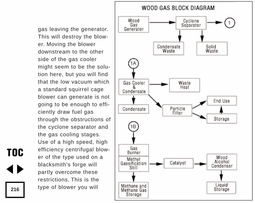
gas leaving the generator.This will destroy the blow-er. Moving the blowerdownstream to the otherside of the gas coolermight seem to be the solu-tion here, but you will findthat the low vacuum whicha standard squirrel cageblower can generate is notgoing to be enough to effi-ciently draw fuel gasthrough the obstructions ofthe cyclone separator andthe gas cooling stages.Use of a high speed, highefficiency centrifugal blow-er of the type used on ablacksmith's forge willpartly overcome theserestrictions. This is thetype of blower you will216
need if you want to fill a storage tank. Of course, the user can try and getthe fuel in the gas generator burning and then just crank the engine overwith the starter until the draw from it pulls enough fuel gas in to start it. Youwill find that this takes quite a while, though. It will require a large batterycapacity and will result in the eventual destruction of the electrical starterthrough overheating.
Another method, used successfully by Mother Earth News in their work,requires starting the engine on gasoline and then switching over to fuel gason the fly. One way that this can be done is by piping the fuel gas into thetop of the carburetor on the running engine. Gasoline is shut off to the car-buretor and fuel gas, mixed with air, takes over running the engine. Thissounds easy, but getting the transition to occur smoothly between fuels (tooccur at all) is very difficult. The Mother Earth method of accomplishing thiswas to place a "T" in the induction system. The carburetor was mounted onone side of the "T" and fuel gas was piped to the other. A flapper valve wasplaced at the junction of the "T" so it could select one fuel system or theother. This method works smoothly, but requires a throttle body in the fuelgas system in addition to the one in the carburation system. The singleadvantage to piping the wood gas into the top of an already existing carbu-retor is that speed regulation of the engine is done with the existing hard-ware of the carburetor itself, thus it could be used with an existing machine
Alternatives to Fossil Fueled Engine/Generators
217
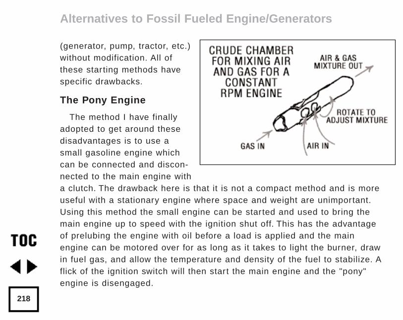
(generator, pump, tractor, etc.)without modification. All ofthese starting methods havespecific drawbacks.
The Pony Engine
The method I have finallyadopted to get around thesedisadvantages is to use asmall gasoline engine whichcan be connected and discon-nected to the main engine witha clutch. The drawback here is that it is not a compact method and is moreuseful with a stationary engine where space and weight are unimportant.Using this method the small engine can be started and used to bring themain engine up to speed with the ignition shut off. This has the advantageof prelubing the engine with oil before a load is applied and the mainengine can be motored over for as long as it takes to light the burner, drawin fuel gas, and allow the temperature and density of the fuel to stabilize. Aflick of the ignition switch will then start the main engine and the "pony"engine is disengaged.
Alternatives to Fossil Fueled Engine/Generators
218
I used a gasoline engine as a "pony" engine because I was experiment-ing with a 350 cubic inch Chevy V8. If the engine is small enough, itcould be motored over using an AC or DC motor and either power line or battery current.
The pony engine method of starting works well with a stationary engineor where space or weight are not a problem. Where these are considera-tions, the dual fuel approach is worth the effort. A diesel engine can also berun off wood gas with almost no modification. In this case, the engine willbe started and run up on diesel fuel. The fuel gas supply will require theusual air mixer and a throttle body before entering the induction of theengine. If constant speed is your goal, you will will also have to add anexternal governor to control the fuel gas throttle body. Once started andswitched over to wood gas, the diesel throttle is set at idle and the smallamount of fuel injected is used to ignite the air/fuel gas mixture in the cylinders. Speed is controlled by the fuel gas throttle body.
I mentioned earlier that wood gas had a high resistance to "knock" or ahigh "octane" rating. This has some interesting ramifications for someonewho is not content to put up with a reduction of power while burning woodgas. Modern gasolines will tolerate a compression ratio of around 9 to 1before the engine starts to knock and self destruct. Wood gas and alcoholwill tolerate compression ratios up to 13 to 1 before this happens. So, it
Alternatives to Fossil Fueled Engine/Generators
219
would be relatively easy to build an engine based on a high output moderndesign, using racing parts, which would recapture all of the lost horse powerthat wood gas costs through higher efficiencies. The efficiency figure of 28%for a gasoline I gave earlier is not immutable. A crude gasoline engine mightonly get 20% efficiency while some all out racing engines would get as highas 50%. The typical modern engine with overhead cam, fuel injection, andelectronic ignition and control systems will get in the neighborhood of 32%.If your philosophy of power production justifies the expenditure, this may bea productive path.
Methyl alcohol is the last fuel I will discuss. Racing engines have beenrun on alcohol for a long time. The now obsolete Indianapolis 500 engineknown as the Meyers Drake "Offy" was a four cylinder engine of about 155cubic inches which routinely produced 750 horse power on alcohol. Anengine burning alcohol fuel has a very high knock resistance and so canuse the highest compression ratios to improve efficiency. On the other hand,methanol requires a lot of heat to evaporate it into a vapor, which makes anengine very hard to start. In addition, methanol has much less heat contentthan gasoline, so it requires much more fuel to do the same work. Thismeans custom jetting carburetors for alcohol - beyond the range which theirmanufacturers designed them for. On top of that, alcohol is very corrosiveand will damage metals, gaskets, fiber parts in carburetors, and hoses not
Alternatives to Fossil Fueled Engine/Generators
220

specifically designed to handle it. It is also one of the cleanest burning fuelsavailable. It is quite possible to have a roaring alcohol fire and not even beable to see the flames in the daylight. So, methanol is a mixed bag. It'savailable in quantity, but you will need a lot of fairly sophisticated mechani-cal knowledge to make use of it reliably; more than this article can cover.
The most direct applications for wood gas are straight-forward. For exam-ple, running a small gas powered generator to charge your battery bank. Butconsider some other ideas:
A removable flexible hose carrying wood gas to the intake of your farmtractor so that PTO-driven implements like saw mill, chippers, compostinghammer mills, and large electric generators could be driven on wood gaswithout any change in the farm tractor.
A large 350 cubic inch V8 engine running at 1900 to 2000 rpm could beused to directly drive a large three phase motor. The imposed 60 hertz linefrequency would make this overdriven motor act like a synchronous genera-tor, feeding electricity back into the grid and earning income as a smallpower station.
Installation of a large V8 engine and truck transmission in a bulldozerchassis, along with the wood gas generator and filters. By running in lowgear this engine will directly replace the slow speed diesel which normallypowers such a machine. I have already built this machine and it is practical.
Alternatives to Fossil Fueled Engine/Generators
221

And of course, as Mother Earth News proved, a wood gas generator canbe used to power a car or truck. In fact a lot of Europe ran on wood gas dur-ing World War II fuel shortages. With modest mechanical skills, this is atechnology you can use now, and it's far safer than steam.
Access
Author: Clifford W. Mossberg, POB 75273, Fairbanks, AK 99707
Plans for wood gas burner units:The Mother Earth News Plans, POB 70, Hendersonville, NC 28793,Wood Gas Generator, Plan #84030
Parts, hardware, and complete burner units:Cloidal Cam Engineering Inc., POB 244, Prior Lake, MN 55377ESMCO, 5555 Boon Ave. N., Minneapolis, MN 55428
Alternatives to Fossil Fueled Engine/Generators
222
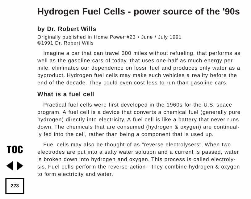
by Dr. Robert WillsOriginally published in Home Power #23 • June / July 1991©1991 Dr. Robert Wills
Imagine a car that can travel 300 miles without refueling, that performs aswell as the gasoline cars of today, that uses one-half as much energy permile, eliminates our dependence on fossil fuel and produces only water as abyproduct. Hydrogen fuel cells may make such vehicles a reality before theend of the decade. They could even cost less to run than gasoline cars.
What is a fuel cell
Practical fuel cells were first developed in the 1960s for the U.S. spaceprogram. A fuel cell is a device that converts a chemical fuel (generally purehydrogen) directly into electricity. A fuel cell is like a battery that never runsdown. The chemicals that are consumed (hydrogen & oxygen) are continual-ly fed into the cell, rather than being a component that is used up.
Fuel cells may also be thought of as "reverse electrolysers". When twoelectrodes are put into a salty water solution and a current is passed, wateris broken down into hydrogen and oxygen. This process is called electroly-sis. Fuel cells perform the reverse action - they combine hydrogen & oxygento form electricity and water.
Hydrogen Fuel Cells - power source of the '90s
223
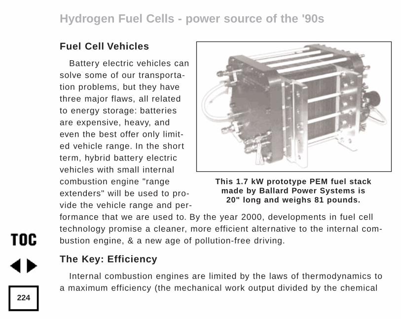
Fuel Cell Vehicles
Battery electric vehicles cansolve some of our transporta-tion problems, but they havethree major flaws, all relatedto energy storage: batteriesare expensive, heavy, andeven the best offer only limit-ed vehicle range. In the shortterm, hybrid battery electricvehicles with small internalcombustion engine "rangeextenders" will be used to pro-vide the vehicle range and per-formance that we are used to. By the year 2000, developments in fuel celltechnology promise a cleaner, more efficient alternative to the internal com-bustion engine, & a new age of pollution-free driving.
The Key: Efficiency
Internal combustion engines are limited by the laws of thermodynamics toa maximum efficiency (the mechanical work output divided by the chemical
Hydrogen Fuel Cells - power source of the '90s
224
This 1.7 kW prototype PEM fuel stack made by Ballard Power Systems is
20" long and weighs 81 pounds.
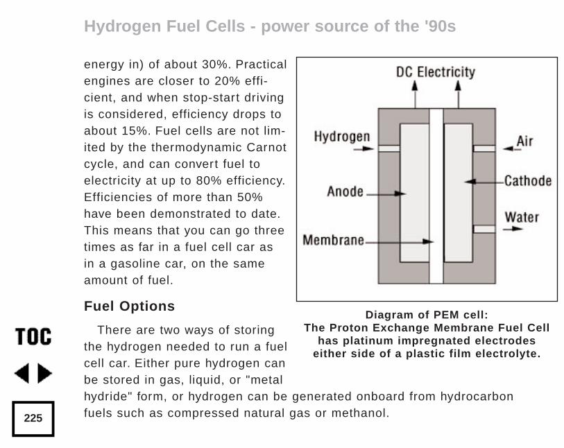
energy in) of about 30%. Practicalengines are closer to 20% effi-cient, and when stop-start drivingis considered, efficiency drops toabout 15%. Fuel cells are not lim-ited by the thermodynamic Carnotcycle, and can convert fuel toelectricity at up to 80% efficiency.Efficiencies of more than 50%have been demonstrated to date.This means that you can go threetimes as far in a fuel cell car asin a gasoline car, on the sameamount of fuel.
Fuel Options
There are two ways of storingthe hydrogen needed to run a fuelcell car. Either pure hydrogen canbe stored in gas, liquid, or "metalhydride" form, or hydrogen can be generated onboard from hydrocarbonfuels such as compressed natural gas or methanol.
Hydrogen Fuel Cells - power source of the '90s
225
Diagram of PEM cell:The Proton Exchange Membrane Fuel Cell
has platinum impregnated electrodes either side of a plastic film electrolyte.
The "reforming" of methanol or other hydrocarbons to produce hydrogenand carbon dioxide has the advantage of easy fuel storage but the disad-vantages of needing a small, onboard chemical processing plant, and stillpolluting the atmosphere with carbon dioxide.
Storage of pure hydrogen in cryogenic liquid or high pressure gaseousforms poses safety hazards that are unacceptable for general transportation.Storage in metal hydrides, where hydrogen atoms lodge in the atomic latticeof metals such as magnesium and titanium, offers safety and ease of use,but carries the penalty of high costs and much added weight (only 2-5% ofthe weight of the storage system is actually hydrogen).
When the system is looked at as a whole, however, this extra weight iscompensated by the reduced weight of the drive system (the fuel cell, elec-tric motor and motor controller) when compared to a gasoline engine andtransmission, and reduced fuel requirements. Fuel cells capable of 10 kWcontinuous output and electric motors rated at up to 100 HP should be avail-able at weights of less than 50 lbs apiece.
The safety of hydrogen as a fuel is often questioned. In fact, hydrogen isin many ways far safer than gasoline - it is non-toxic and disperses quickly.So little gaseous hydrogen is available in a hydride storage system (andheat is needed to liberate gas from the metal matrix) that such systems areinherently far safer than gasoline storage in today's cars.
Hydrogen Fuel Cells - power source of the '90s
226
A Hydrogen Economy
A hydrogen powered car needs a means to refuel. This could take theform of hydrogen refilling stations where hydrogen is piped or trucked fromcentral generating sites. These "gas" stations will be worthy of their name.Hydrogen is produced in large quantities today from natural gas via areforming process. This is the cheapest source at present. In future, we canlook forward to large scale photovoltaic/electrolysis power stations in thesouthern U.S.A. producing hydrogen for the whole country. Pipelines, includ-ing the existing natural gas network, could be used for distribution.
Hydrogen can also be produced from water and electricity via electrolysis.This could be done actually at the "gas" stations, or alternately, small elec-trolysers could be installed in cars, or in home garages, to provide a meansof refueling from grid electric power. In the short term, home or onboardelectrolysers are the only alternative, despite higher fuel costs, as a networkof hydrogen gas stations will take some time to evolve.
Economics
Dr. John Appleby of Texas A&M University's Center for ElectrochemicalSystems & Hydrogen Research has calculated that a fuel cell car poweredby hydrogen made from natural gas could cost as little as 1.5¢ per mile infuel cost, compared to 4.4¢ per mile for gasoline. A fuel cell car could cost
Hydrogen Fuel Cells - power source of the '90s
227
one third as much to run as the car of today! Maintenance costs would beminimal with no engine oil changes, no spark plugs, no exhaust system, andwith the regenerative braking reducing the mechanical brake wear. The fuelcell life could be as long as 100,000 hours. Appleby puts the cost of elec-trolytic hydrogen fueling at 5.6¢ per mile, and straight battery electric vehiclesat 3.5¢ per mile plus 2 - 5¢ per mile in battery replacement costs.
The benefits of zero-pollution vehicles, such as the fuel cell car, should alsobe included in economic comparisons. Estimates of the social and healthcosts of burning gasoline in our cities range from $1.15 up to $4.50 per gallonof fuel.
Another researcher at Texas A&M, Dr. David Swan, has predicted that fuelcell system costs can drop to $272 per kW with mass production. He esti-mates a complete 75 kW peak, 25 kW continuous fuel cell/battery hybrid drivesystem would cost $8,550, about $1000 more than a conventional gasolinedrive. Other estimates are as low as $4,450 for a complete drive system.
How long to Market?
While government and car manufacturers' predictions of fuel cell cars rangefrom 2005 to 2050, recent advances have made practical cars possible withina few years. Many small companies are working on fuel cells for vehicles.Ballard Power Systems in Vancouver, B.C. plans to have a fuel cell powered
Hydrogen Fuel Cells - power source of the '90s
228
bus on the road by 1992 and are also working with General Motors on auto-mobile applications. Dr. Roger Billings of the American Academy of Science,Independence, MO, has developed fuel cells that are not only small, lightand efficient, but can operate in reverse as electrolysers. He plans to delivera demonstration fuel cell vehicle to the Penn. Energy Office in mid-1991.
We are about to leave oil behind, and enter the age of the fuel cell.
AccessAuthor:
Dr. Robert Wills, Skyline Engineering, Potato Hill Road, RR#1, Box220-C, Fairlee, VT 05045 • 802-333-9305. Dr. Wills is a consultingengineer who specializes in photovoltaic system design and Co-Director of the American Tour de Sol, the Solar & Electric car race.
Fuel Cell Makers:Ballard Power Systems, Inc., 980 West 1st Street, Unit 107, NorthVancouver, B.C. V7P 3N4, CANADA • 604-986-9367.
Ergenics, 247 Margret King Ave., Ringwood, NJ 07456 • 201-962-4480.Skyline Engineering AD
Hydrogen Fuel Cells - power source of the '90s
229
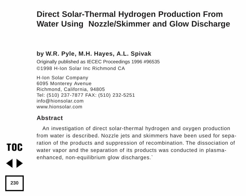
by W.R. Pyle, M.H. Hayes, A.L. SpivakOriginally published as IECEC Proceedings 1996 #96535©1998 H-Ion Solar Inc Richmond CA
H-Ion Solar Company6095 Monterey AvenueRichmond, California, 94805Tel: (510) 237-7877 FAX: (510) [email protected]
Abstract
An investigation of direct solar-thermal hydrogen and oxygen productionfrom water is described. Nozzle jets and skimmers have been used for sepa-ration of the products and suppression of recombination. The dissociation ofwater vapor and the separation of its products was conducted in plasma-enhanced, non-equilibrium glow discharges.`
Direct Solar-Thermal Hydrogen Production FromWater Using Nozzle/Skimmer and Glow Discharge
230
Summary
In this report we describe the status of our work with a solar water dissoci-ation gas phase reactor:
Solar radiant energy was concentrated by a parabolic mirror to producehigh temperatures on a nozzle inside a solar reactor fed with water vapor(steam) at low pressure, to produce hydrogen and oxygen.
• A ceramic dissociator-nozzle was used as the target (absorber) for theconcentrated solar-beam image. Water vapor was fed to the hot dissocia-tor-nozzle by a feed-ring. Expansion of the water and its dissociationproducts into a lower pressure region was employed to provide quenching.
• A conical skimmer was used to separate the dissociated water vaporproducts, hydrogen and oxygen, from the unconverted water vapor in theexpanding dissociator-nozzle jet. The objective is to separate the hydro-gen and oxygen products from one another before they recombine.
• The dissociator-nozzle is operated with an electrical glow dischargebetween the water vapor feed-ring and the nozzle inlet. In this way thesteam flow field, where the radiation and convection heat transfer takesplace, was populated with free electrons, ions and molecules in the excit-ed state. The radiation absorption capture cross-section for water vaporwas altered by the plasma glow discharge.
Direct Solar-Thermal Hydrogen Production
231
• The product gas stream (containing hydrogen, oxygen and water) fromthe dissociator-nozzle’s exhaust jet flow field was operated in a glowdischarge. This affects the flow-field between the dissociator-nozzle jetand a conical-skimmer. The expanding jet flow-field downstream of thedissociator-nozzle separates the water decomposition products spatially,enriching the core of the jet flow-field with the heavier oxygen andwater, and enriching the periphery of the jet flow-field with the lighterhydrogen. Transverse diffusion of hydrogen appears to be responsible forthe separation.
• Progress to date includes:
a) Operation of the reactor for over 50 hours "on-sun" at 2600-2900° Knozzle surface temperature without failure of materials.
b) Dissociation of water and separation of hydrogen at 1 to 2% overallefficiency (solar to hydrogen.)
Introduction
A sustainable, non-polluting energy currency is required to provide forhuman needs such as cooking, heating, transportation, electricity produc-tion, and refrigeration. An economically viable method for producing largequantities of hydrogen from water using sun-light would satisfy this need, ina "Hydrogen Economy".
Direct Solar-Thermal Hydrogen Production
232
Pioneering studies of solar hydrogen and oxygen production from wateroccurred throughout the world during the 1970s and early 1980s as aresponse to the oil shocks of 1973 and 1978/1979. After a lull in activitiesduring the mid and late 1980s, interest in direct water dissociation and otherhydrogen production technologies has again increased during the early1990s due to increasing environmental problems.
Water Dissociation to Produce Hydrogen and Oxygen
Our research objective is to develop a process that can attain a high levelof water vapor dissociation and efficiently separate the hydrogen from theoxygen and un-converted water vapor.
At high temperatures, above about 1800° K, water vapor (steam) begins todissociate into a mixture of H2, O2, H2O, O, H and OH. The extent of dissoci-ation increases with increasing temperature and decreasing pressure. Thewater and the diatomic hydrogen and oxygen species completely dissociateinto H (atomic hydrogen) and O (atomic oxygen) above about 3500° K underequilibrium conditions at 1 mm Hg absolute pressure.
Direct Solar-Thermal Hydrogen Production
233
Endothermic Water Vapor Dissociation Reactions
Endothermic reactions can be carried out with the aid of electricity, asin electrolysis. However, thermal power from concentrated solar radiationcan be used without any mechanical or electrical input, and without theaid of any catalyst, to achieve water dissociation. The direct thermalmethod has two advantages: it is very simple in its principle, and it is ver-satile and adaptable to many endothermic gas-phase reactions. Thismethod does not suffer from the corrosive reagent problems of variousmulti-step lower temperature thermo-chemical cycles. New problemsarise, however, in finding reactor materials capable of withstanding thehigher temperatures required with one-step concentrated radiation water-thermolysis. The materials used in the reactor must be capable of with-standing the thermal cycling and shock brought about by the intermittentnature of solar diurnal and weather cycles.
Direct Solar-Thermal Hydrogen Production
234
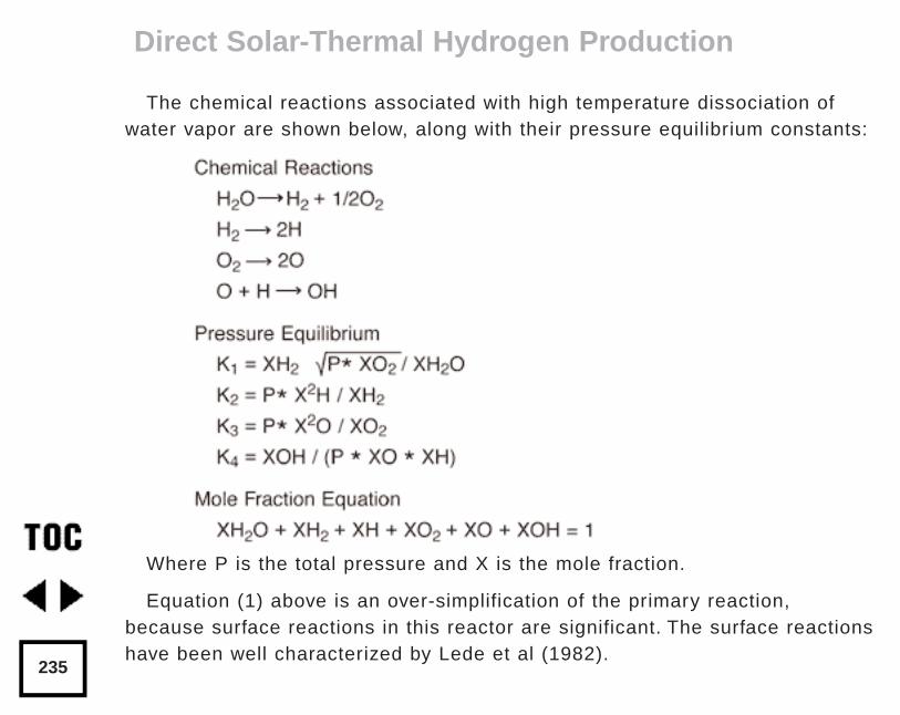
The chemical reactions associated with high temperature dissociation ofwater vapor are shown below, along with their pressure equilibrium constants:
Where P is the total pressure and X is the mole fraction.
Equation (1) above is an over-simplification of the primary reaction,because surface reactions in this reactor are significant. The surface reactionshave been well characterized by Lede et al (1982).
Direct Solar-Thermal Hydrogen Production
235
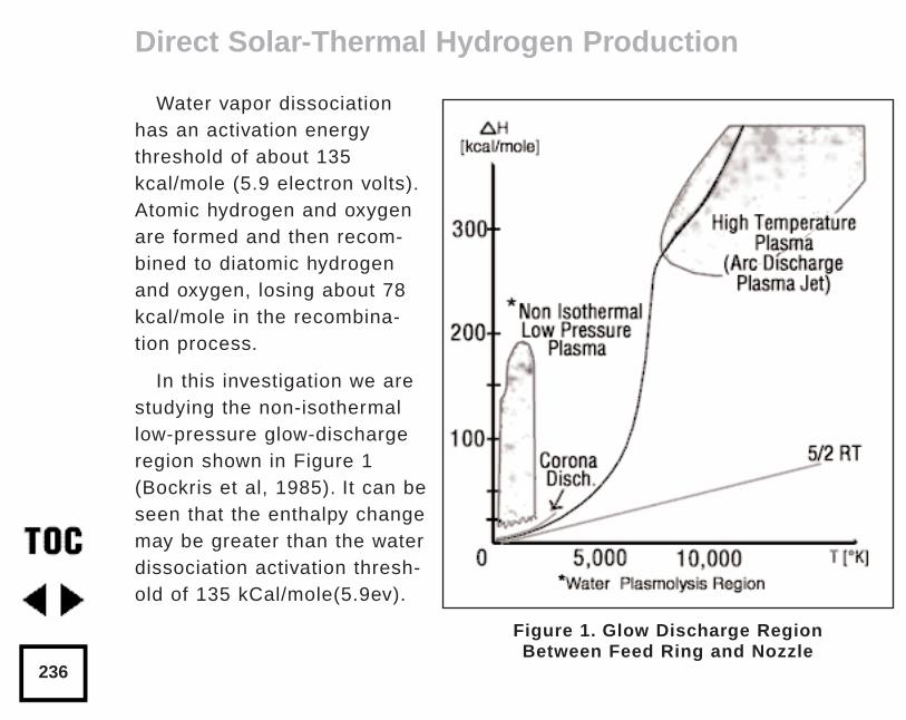
Water vapor dissociationhas an activation energythreshold of about 135kcal/mole (5.9 electron volts).Atomic hydrogen and oxygenare formed and then recom-bined to diatomic hydrogenand oxygen, losing about 78kcal/mole in the recombina-tion process.
In this investigation we arestudying the non-isothermallow-pressure glow-dischargeregion shown in Figure 1(Bockris et al, 1985). It can beseen that the enthalpy changemay be greater than the waterdissociation activation thresh-old of 135 kCal/mole(5.9ev).
Direct Solar-Thermal Hydrogen Production
236
Figure 1. Glow Discharge Region Between Feed Ring and Nozzle
Non-Equilibrium Plasma-Chemical Reactions Associated with Water Vapor Glow Discharges
The process of decomposition of water in the plasma state can be accom-plished at highest efficiency where the electron temperature is not sufficientfor intense excitation of the electron states, and the larger portion of the elec-tron's energy contributed to the discharge is expended for excitation of vibra-tion modes and for dissociative attachment (Melik-Asloanova et al, 1978).
Dissociation of water vapor molecules is accomplished by successive stagesof water oscillative excitation, population of highly excited states and, finallyby reactions with participation of H2O* (where the * denotes the vibrationallyexcited state of water). The reaction is initialized in the bi-molecular act:
H2O* + H2O* => H + OH + H2O
The radicals H and OH initiate a reaction with participation of the oscilla-tively excited molecules:
H + H2O* => H2 + OH
OH + H2O* => H + H2O2
Water decomposition by dissociative attachment requires that in each reac-tion an electron disappears and a negative ion is produced. Plasmochemical
Direct Solar-Thermal Hydrogen Production
237
dissociative attachment reactions become energetically effective wheneach electron produced in the plasma can repeatedly participate in the dis-sociative attachment process. Multiple use of the electron becomes possi-ble due to a high rate of negative ion collapse by electron impact. Thechain process initializes:
e + H2O => H- + OH
H- + e => H + e + e
Termination of the chain results from recombination with water and OHin a three-body collision:
H + OH + H2O => H2O + H2O
The parallel channel of the chain extension has poorer kinetics becauseof a higher activation barrier of the limiting process:
OH + H2O => H2 + HO2
HO2 + H2O => H2O2 + OH
The total efficiency of the process depends on the energy losses in thedischarge, the efficiency associated with the negative contribution of thechain-breaking reaction, the heat losses of the excited-state reactions, andfinally on the efficiency of the reaction relative to the oscillative relaxation.
Direct Solar-Thermal Hydrogen Production
238
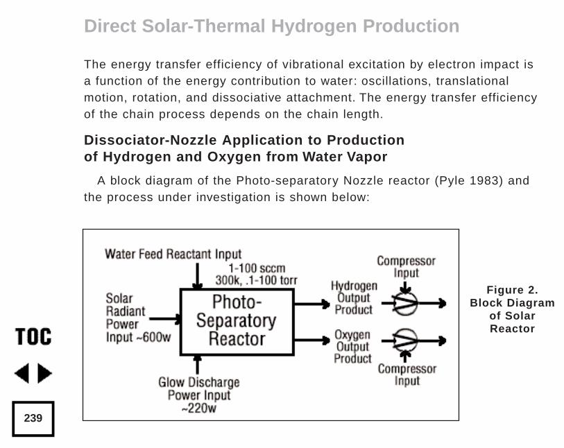
The energy transfer efficiency of vibrational excitation by electron impact isa function of the energy contribution to water: oscillations, translationalmotion, rotation, and dissociative attachment. The energy transfer efficiencyof the chain process depends on the chain length.
Dissociator-Nozzle Application to Productionof Hydrogen and Oxygen from Water Vapor
A block diagram of the Photo-separatory Nozzle reactor (Pyle 1983) andthe process under investigation is shown below:
Direct Solar-Thermal Hydrogen Production
239
Figure 2.Block Diagram
of SolarReactor
Concentration and Absorption of Sunlight in Solar Reactor
Sun-light was concentrated using a parabolic mirror and directed throughthe entrance window of a high-temperature gas-phase reactor. Inside thesolar reactor the concentrated radiant energy was focused onto a trumpet-shaped ceramic dissociator-nozzle. An optical pyrometer with a video cam-era looks through a prism and a hole in the concentrator mirror, thenthrough the quartz reactor window to view the dissociator-nozzle surfaceand obtain nozzle surface temperatures.
The solar spectrum, at sea level on Earth with air mass of 1, loses someenergy bands due to the water vapor absorption which occurs as the light ispassing through the atmosphere, especially in the near UV. This absorptionlimits the energy spectrum available for water dissociation at the earth’s sur-face. We used re-radiation from a hot surface (the nozzle) to enhance gasheat transfer and create a surface reaction site.
Solar heat source temperature can be calculated as a function of the con-centrator optical concentration ratio, reflection coefficient, and arriving solarpower density.
By raising the temperature of the nozzle surface to a sufficiently highvalue (using the nozzle as a target for concentrated sunlight) and dropping
Direct Solar-Thermal Hydrogen Production
240
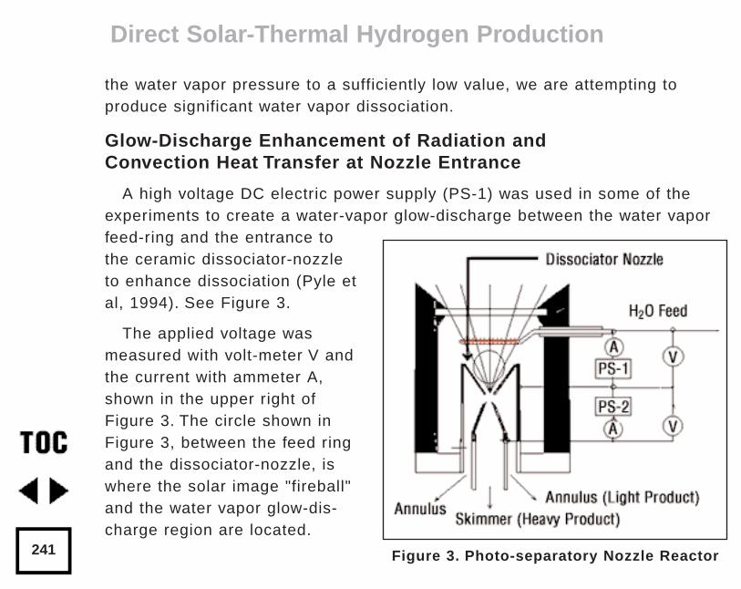
the water vapor pressure to a sufficiently low value, we are attempting toproduce significant water vapor dissociation.
Glow-Discharge Enhancement of Radiation and Convection Heat Transfer at Nozzle Entrance
A high voltage DC electric power supply (PS-1) was used in some of theexperiments to create a water-vapor glow-discharge between the water vaporfeed-ring and the entrance tothe ceramic dissociator-nozzleto enhance dissociation (Pyle etal, 1994). See Figure 3.
The applied voltage wasmeasured with volt-meter V andthe current with ammeter A,shown in the upper right ofFigure 3. The circle shown inFigure 3, between the feed ringand the dissociator-nozzle, iswhere the solar image "fireball"and the water vapor glow-dis-charge region are located.
Direct Solar-Thermal Hydrogen Production
241 Figure 3. Photo-separatory Nozzle Reactor
The partially dissociated water vapor was allowed to pass through the dis-sociator-nozzle throat and expand into a lower pressure region. The pressureinside the dissociator-nozzle tube (downstream) must be lower than at theentrance (dissociation region) to create the driving force for sonic flowthrough the nozzle throat (pressure ratio > 0.55) , and produce a jet andshock-wave down stream.
In our application, a sonic dissociator-nozzle geometry was used becausethis was the easiest to fabricate using quartz tubing in the laboratory.
All gases at room temperature are excellent electrical insulators. In order tomake them electrically conducting, a sufficient number of charge carriers haveto be generated. If a sufficiently high electrical field is applied to a pair ofelectrodes separated by a volume of the gas, an electrical breakdown of theoriginally non-conducting gas establishes a conducting path through the elec-trode gap, producing an array of phenomena known as gaseous discharges.
We desire a steady-state dc glow discharge for our solar plasma reactor,to obtain a higher electron population density with relatively low electricalpower consumption.
After breakdown, the current A rises and voltage V drops to steady-statevalues. The discharge voltage depends on the current and certain propertiesof the discharge tube, such as gas type, gas pressure, electrode material,
Direct Solar-Thermal Hydrogen Production
242
and electrode temperature. A current suppression (or ballast) resistor isneeded to limit the current through the gas-plasma after breakdown occurs.We used 10,000 to 18,000 ohm suppression resistors in the Photo-separato-ry Nozzle reactor.
Heat is supplied to the dissociator-nozzle (which is also the cathode elec-trode for the glow discharge) by the concentrated solar beam, and it oper-ates in glow discharge with low cathode fall. Cooling of the nozzle surfaceby electron boil-off occurs under direct thermionic emission process condi-tions at very high temperatures. Indirect emission processes (secondaryemission processes) are also important to consider: electrons are ejectedfrom the surface of the nozzle by energetic particles such as ions and pho-tons in the glow discharge.
Glow Discharge Applied Between Dissociator Nozzle and Skimmer Separator
A supersonic beam skimmer was installed behind the shock wave to sepa-rate hydrogen and oxygen from the partially dissociated water vapor (Beckeret al 1955). See Figure 3 (p.241).
The supersonic beam skimmer used was a knife-edged cone. The skimmerwas positioned with micrometers so that its entrance was at the down-stream edge of the shock-wave envelope produced inside the dissociator -
Direct Solar-Thermal Hydrogen Production
243
nozzle. An appropriate pressure ratio was applied between the low pressuredissociator-nozzle jet region and the beam skimmer interior to improve theseparation factor for hydrogen and oxygen production. This jet separatorfunctions by transverse gas diffusion. The hydrogen and oxygen (plusunconverted water vapor) are separated because the hydrogen gas diffusestransversely (relative to the jet flow axis, more rapidly than oxygen orwater), due to its lower mass.
A second high voltage DC electric power supply (PS-2) was used to cre-ate a glow discharge between the sonic dissociator-nozzle and the conicalskimmer nozzle to study separation enhancement by cataphoresis.Cataphoresis is the spatial gas density gradient which forms near a cathodewithin a glow discharge. Cataphoretic efficiency has been observed todecrease with increasing temperature, however.
The glow-discharge between the dissociator-nozzle and the skimmer-noz-zle also allows shock-wave visualization by a video camera which is aimedthrough a viewing slit in the reactor wall. The video camera is attached to acoherent optical fiber bundle and illuminated with a He-Ne laser throughanother incoherent optical fiber bundle to allow observation of the dissocia-tor-nozzle and skimmer separation distance, as the skimmer is moved in orout of the jet.
Direct Solar-Thermal Hydrogen Production
244
Enrichment of heavier-mass species occurs in the core of the gas jet.Enrichment of the lighter-mass species occurs in the periphery of the gas jet.
The free molecular diffusion separation arises from the disparity in the ther-mal velocity of light and heavy gas molecules, for gases with the same massflow velocity and local temperature. The heavier species have a lower thermalvelocity and expand less (laterally) after the transition plane, remaining moreconcentrated at the beam center.
In moving the skimmer transversely, a qualitative measurement of the degreeof beam spreading is obtained. A much broader spreading is observed for lightspecies (hydrogen) than for heavy species.
In the case of a fixed skimmer-orifice dimension, an axially movable skimmeris necessary to achieve comparable beam intensities for different gases. Themass separation factor is approximately proportional to the mass ratio whenthe skimmer-interference and background-penetration effects are minimized.
Separation Factor =
[(Heavy Core Gas, M%) (Light Peripheral Gas, M%)] / [(Heavy Peripheral Gas, M%) (Light Core Gas, M%)]
Direct Solar-Thermal Hydrogen Production
245
Glow Discharge Power Supply Requirements
In the dark (no concentrated sunlight), with water vapor pressures in thePhoto-separatory Nozzle reactor's normal pressure regime, the power sup-ply voltage required for sustaining normal glow may be about 700, whereasunder concentrated sun-beam illumination the normal glow voltage is onlyabout 200. The current requirement is on the order of 1-3 ma under eitherdark or illuminated conditions. The use of higher pressure requires the useof higher current. The glow-discharge power is only a small fraction of thepower arriving via the concentrated sun-beam, about 1 to 2 watts typically.This electrical power requirement can easily be met by a small photovoltaiccell array.
The glow-discharge power for the lower pressure gas region between thedissociator-nozzle and the skimmer is of the same order as for the feed-ringto dissociator-nozzle power, 1 to 2 watts.
Description of Experimental Apparatus
The complete Photo-separatory Nozzle reactor assembly is shown inFigure 4, next page.
A computer program, called Iontrack, calculates the elevation and azimuthof the sun based on the time of day, and the latitude and longitude of the
Direct Solar-Thermal Hydrogen Production
246
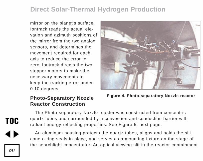
mirror on the planet's surface.Iontrack reads the actual ele-vation and azimuth positions ofthe mirror from the two analogsensors, and determines themovement required for eachaxis to reduce the error tozero. Iontrack directs the twostepper motors to make thenecessary movements to keep the tracking error under0.10 degrees.
Photo-Separatory NozzleReactor Construction
The Photo-separatory Nozzle reactor was constructed from concentricquartz tubes and surrounded by a convection and conduction barrier withradiant energy reflecting properties. See Figure 5, next page.
An aluminum housing protects the quartz tubes, aligns and holds the sili-cone o-ring seals in place, and serves as a mounting fixture on the stage ofthe searchlight concentrator. An optical viewing slit in the reactor containment
Direct Solar-Thermal Hydrogen Production
247
Figure 4. Photo-separatory Nozzle reactor
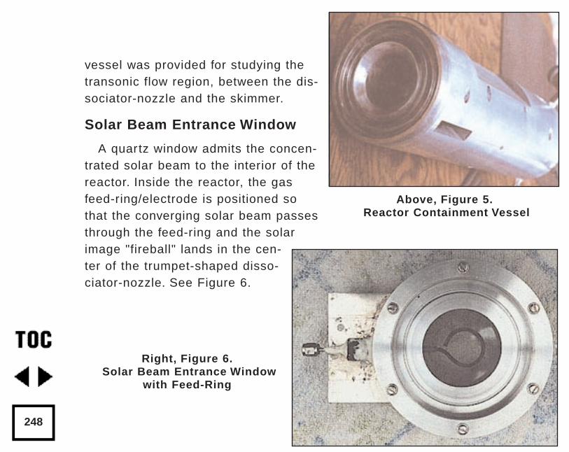
vessel was provided for studying thetransonic flow region, between the dis-sociator-nozzle and the skimmer.
Solar Beam Entrance Window
A quartz window admits the concen-trated solar beam to the interior of thereactor. Inside the reactor, the gasfeed-ring/electrode is positioned sothat the converging solar beam passesthrough the feed-ring and the solarimage "fireball" lands in the cen-ter of the trumpet-shaped disso-ciator-nozzle. See Figure 6.
248
Above, Figure 5.Reactor Containment Vessel
Right, Figure 6.Solar Beam Entrance Window
with Feed-Ring
Gas (Water Vapor) Feed-Ring Electrode
The feed-ring electrode was made from a loop of stainless steel tubing.The tubing was welded closed at one end and drilled with feed holes 0.508mm (0.020 inches) diameter chamfered 1 mm (0.040 inches) periodically at1.27 cm (0.5 inch) intervals along its length. The tubing was then rolledaround a mandrel to form the feed-ring electrode. A quartz tubing sleevewas used as a feed-through insulator at the reactor window retainer wall tosupply reactant gas and electrical power. The electrical power supply con-nection to the feed-ring electrode is made outside the reactor on the stain-less steel gas feed tube.
It is important to operate the reactor when it is "on-sun" with water vaporflowing to the feed ring. In one experiment, water vapor feed was interruptedand the stainless steel feed-ring was evaporated. The feed-ring turns blackafter operation on-sun for a few hours, but is not damaged by the beam aslong as the water vapor feed is continuous.
Sonic Dissociator-Nozzle/Electrode Fabrication
The dissociator-nozzle is a sonic nozzle with a trumpet-shaped converg-ing entrance section made from a cylindrical quartz tube. A sealing flatflange was fused to the opposite end of the tube. A conductive thin film of
Direct Solar-Thermal Hydrogen Production
249
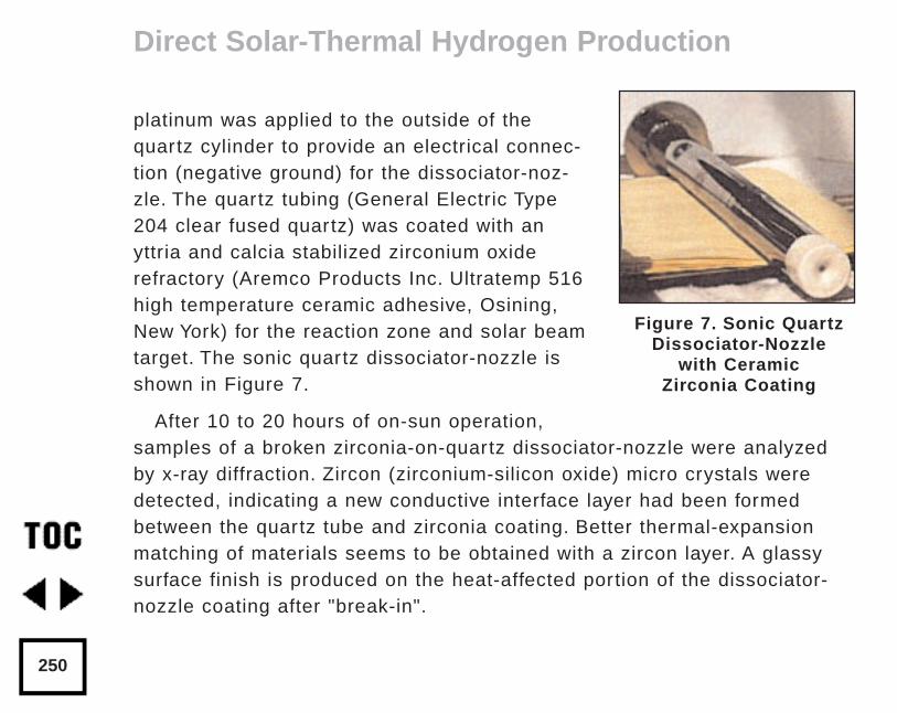
platinum was applied to the outside of thequartz cylinder to provide an electrical connec-tion (negative ground) for the dissociator-noz-zle. The quartz tubing (General Electric Type204 clear fused quartz) was coated with anyttria and calcia stabilized zirconium oxiderefractory (Aremco Products Inc. Ultratemp 516high temperature ceramic adhesive, Osining,New York) for the reaction zone and solar beamtarget. The sonic quartz dissociator-nozzle isshown in Figure 7.
After 10 to 20 hours of on-sun operation,samples of a broken zirconia-on-quartz dissociator-nozzle were analyzedby x-ray diffraction. Zircon (zirconium-silicon oxide) micro crystals weredetected, indicating a new conductive interface layer had been formedbetween the quartz tube and zirconia coating. Better thermal-expansionmatching of materials seems to be obtained with a zircon layer. A glassysurface finish is produced on the heat-affected portion of the dissociator-nozzle coating after "break-in".
Direct Solar-Thermal Hydrogen Production
250
Figure 7. Sonic QuartzDissociator-Nozzle
with CeramicZirconia Coating
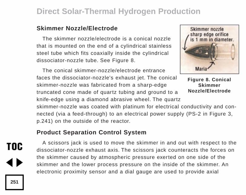
Skimmer Nozzle/Electrode
The skimmer nozzle/electrode is a conical nozzlethat is mounted on the end of a cylindrical stainlesssteel tube which fits coaxially inside the cylindricaldissociator-nozzle tube. See Figure 8.
The conical skimmer-nozzle/electrode entrancefaces the dissociator-nozzle's exhaust jet. The conicalskimmer-nozzle was fabricated from a sharp-edgetruncated cone made of quartz tubing and ground to aknife-edge using a diamond abrasive wheel. The quartzskimmer-nozzle was coated with platinum for electrical conductivity and con-nected (via a feed-through) to an electrical power supply (PS-2 in Figure 3,p.241) on the outside of the reactor.
Product Separation Control System
A scissors jack is used to move the skimmer in and out with respect to thedissociator-nozzle exhaust axis. The scissors jack counteracts the forces onthe skimmer caused by atmospheric pressure exerted on one side of theskimmer and the lower process pressure on the inside of the skimmer. Anelectronic proximity sensor and a dial gauge are used to provide axial
Direct Solar-Thermal Hydrogen Production
251
Figure 8. ConicalSkimmer
Nozzle/Electrode
position information. The spacing between the dissociator-nozzle and skim-mer is of the order of one nozzle diameter (about 1mm.) The skimmer can bemoved from about 0.1mm to about 2.0mm downstream of the dissociator-nozzle. Depending on the pressure in the region between the dissociator-nozzle and the skimmer, this distance is approximately 1 mean-free-path(between atom/molecular collisions).
An eccentric is used to move the skimmer from right/left and up/downaround its pivot point. The pivot point is located about 22 cm downstreamfrom the dissociator-nozzle’s exit orifice. The pivot point is made from 3 dim-ples inside the dissociator-nozzle tube. Two more proximity detectors and dialgauges provide up/down and right/left skimmer position information.
Product Gas Sampling System
Sampling valves are located in the two product discharge lines. Each sam-pling valve can admit product gas into the mass spectrometer. The spectrafrom each product line are alternately taken; then the mass spectrometerbackground gas pressure spectrum is subtracted from each. The mass ratios for the light and heavy products are calculated and used to obtain aseparation factor.
Direct Solar-Thermal Hydrogen Production
252
Mass Flowmeters
The mass-flow rates of the water vapor feed and the skimmer (heavyproduct) and annulus (light product) were measured with Teledyne Hastings-Raydist model ST and model HFM-200H mass flow meters.
Using the three mass-flow meters allowed us to perform a mass balanceacross the reactor to obtain measurement closure with the flow meters (as acalibration and leak check.)
Optical Pyrometer for Nozzle Surface Temperature Measurement
A Pyro Micro-Optical Pyrometer made by the Pyrometer InstrumentCompany Inc. (Northvale N.J.) was used to measure the temperature of thedissociator-nozzle surface under different operating conditions. We used anEC-6 high temperature range filter and a 90° M-14 prism to view the disso-ciator-nozzle. Corrections to the indicated temperature were made for theprism, the filter, the range selection, and the reactor window transmissionloss for any given temperature.
We normally measure temperatures in the 2300° K to 2800° K range atthe nozzle surface, depending on the water vapor feed pressure and thesolar beam flux. Stagnation temperatures as high as 3250° K have been
Direct Solar-Thermal Hydrogen Production
253
measured on the nozzle surface (somewhat higher than the published melt-ing point of zirconia.)
Pumping requirements
Pumping the products from low pressure to atmospheric pressure or high-er requires compression work, which is a parasitic loss in the overall effi-ciency of the process. The losses for the oxygen-rich stream compressorand the hydrogen-rich stream compressor must be minimized by selectingreactor pressures no lower than necessary, and by the use of efficient compressor designs.
The net power required to pump the process fluids in this reactor wasabout 18 watts.
To compress the products adiabatically (no cooling) from 1 Torr to oneatmosphere with an inlet temperature of 300° K would require about 50 kJ/g-mole (11.9 kcal/g-mole). Isothermal compression (with intercooling) wouldrequire only about 1/ 3 as much compression work.
Direct Solar-Thermal Hydrogen Production
254
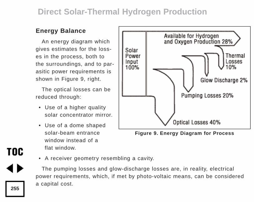
Energy Balance
An energy diagram whichgives estimates for the loss-es in the process, both tothe surroundings, and to par-asitic power requirements isshown in Figure 9, right.
The optical losses can bereduced through:
• Use of a higher qualitysolar concentrator mirror.
• Use of a dome shapedsolar-beam entrance window instead of aflat window.
• A receiver geometry resembling a cavity.
The pumping losses and glow-discharge losses are, in reality, electricalpower requirements, which, if met by photo-voltaic means, can be considereda capital cost.
Direct Solar-Thermal Hydrogen Production
255
Figure 9. Energy Diagram for Process
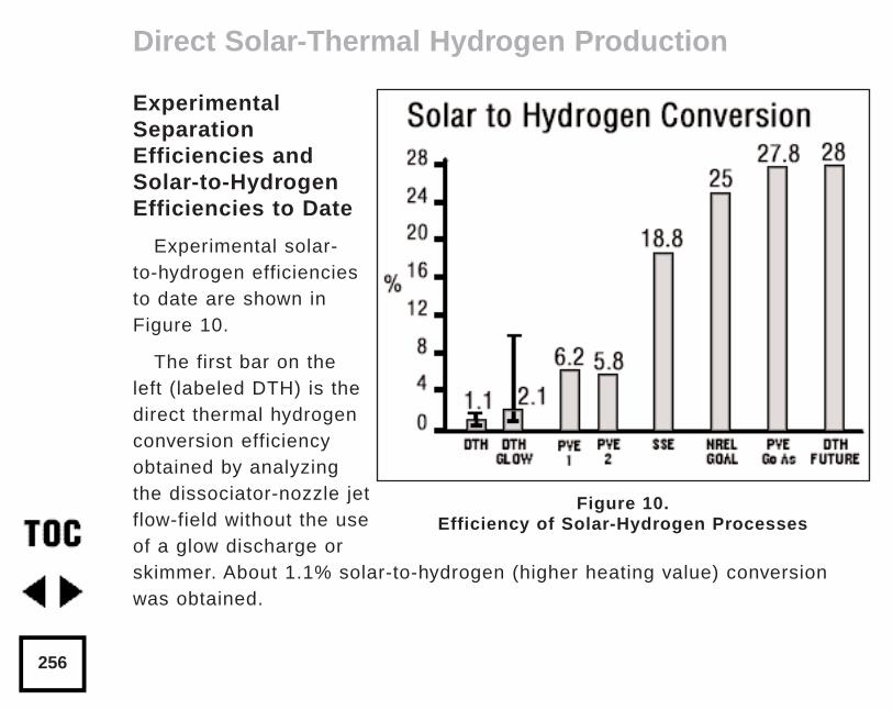
ExperimentalSeparationEfficiencies andSolar-to-HydrogenEfficiencies to Date
Experimental solar-to-hydrogen efficienciesto date are shown inFigure 10.
The first bar on theleft (labeled DTH) is thedirect thermal hydrogenconversion efficiencyobtained by analyzingthe dissociator-nozzle jetflow-field without the useof a glow discharge orskimmer. About 1.1% solar-to-hydrogen (higher heating value) conversionwas obtained.
Direct Solar-Thermal Hydrogen Production
256
Figure 10.Efficiency of Solar-Hydrogen Processes
The second bar (labeled DTH Glow) shows an improvement in solar tohydrogen conversion to about 2.1% when a glow discharge was applied andthe skimmer and annulus hydrogen production was added together. Themaximum and minimum measured values are shown about the mean.
The third bar (labeled PVE1) shows the solar-to-hydrogen efficiencyobtained using silicon photovoltaic cells and an alkaline electrolyzer. Thefourth bar (labeled PVE2) shows the results of another photovoltaic electrol-ysis system.
The conversion efficiency for a solar dish Stirling generator combined withan alkaline electrolyzer [75% efficient] is labeled SSE in Figure 10.
The next bar (labeled NREL Goal) shows the long term solar-to-hydrogenefficiency goal established by the National Renewable Energy Laboratory,for reference purposes.
Multi-junction single crystal gallium arsenide solar cells with future 37%solar-to-electrical efficiency combined with a 75% efficient alkaline elec-trolyzer is labeled PVE Ga As.
The bar (labeled DTH Future) indicates that the future direct thermalhydrogen process may compete with other known methods on an efficiencybasis. It may have the further advantage that it does not use expensive single crystal materials.
Direct Solar-Thermal Hydrogen Production
257
Micro-Nozzle Arrays and Scale-Up
Micro-nozzle arrays may allow scale-up of the process for a wide areasolar reactor receiver. With smaller nozzles, the mean-free-path dimensionswill also be smaller, and higher operating pressures will be allowable in prin-ciple. The higher operating pressure will result in a reduction of parasiticcompression work required .
The arrays can be arranged in matrices or linearly. We can envision arraysof solar-hydrogen reactors along two parallel pipe lines, running from anarea with high insolation, to supply cities. Existing natural gas pipelinescould be used to transport the hydrogen and oxygen products separately totheir point of use. Alternatively, one pipeline could be used to transporthydrogen to the point of use and the oxygen could be vented.
Recommendations for Future Research and Experimentation
We have seen that some direct thermal hydrogen production can beobtained in this reactor simply by passing water vapor through a hot ceramicnozzle (1.1%). We have also found that impressing a glow-discharge acrossthe dissociator-nozzle almost doubles the conversion (2.1%). The separationfactor for the skimmer has not yet been optimized. More work remains to
Direct Solar-Thermal Hydrogen Production
258
obtain accurate spatial calibration of the skimmer, and investigate the effectof pressure, flow separation, and glow discharge on the separation efficiency.At this time, the amount of recombination which occurs after dissociation isunknown. However, we feel there are very exciting possibilities for improve-ment of the process.
Further improvements in product gas analysis (mass spectrometer) calibra-tion and skimmer nozzle position calibration are needed to remove uncertain-ty from the measurements and provide real-time data during "on-sun" experi-mental runs.
Acknowledgments
We are grateful for the suggestion by John Green to consider the separato-ry-nozzle, as applied in mass-spectroscopy, to the separation of dissociatedwater-vapor in a solar reactor.
We thank J.D. Healy, E.C. Petersen, and R. Cortez for their assistance inconstructing and trouble-shooting the apparatus for these experiments.
References
Becker, E.W. et al, 1955, The Separatory Nozzle: a New Device forSeparation of Gases and Isotopes, Z. Naturforschg, Part A, Vol.10a,pp565-572.
Direct Solar-Thermal Hydrogen Production
259
References (continued)
Bockris, J.O.M. et al, 1985, On the Splitting of Water, InternationalJournal of Hydrogen Energy, Vol. 10 No. 30, pp.179-201
Lede, J., Lapique, F., Villermaux, J., Cales, B., Baumard, J.F., andAnthony, A.M., 1982, Production of Hydrogen by Direct ThermalDecomposition of Water, Preliminary Investigation, InternationalJournal of Hydrogen Energy, Vol.7, No.12, pp.939-950.
Melik-Asloanova, T.A., Abbosov, A.S., Shilnikov,V.I., 1978, Dissociationof Water Vapor in Supersonic Flow of Non-equilibrium Plasma,Proceedings World Hydrogen Energy Conference 2, pp.1063-1069.
Pyle, W.R., 1983, Photo-separatory Nozzle, U.S. Patent No.4,405,594.
Pyle, W.R., Hayes, M.H., Healy, J.D., Petersen, E.C., Spivak, A.L.,Cortez, R., 1994 Direct-Thermal Solar Hydrogen Production fromWater Using Nozzles/Skimmers and Glow Discharge in the Gas Phaseat Low Pressure and High Temperature, H-Ion Solar Company, NRELTask No. HY413801, Subcontract No. AAP-4-14240-01, Richmond,California, pp.1-63.
Direct Solar-Thermal Hydrogen Production
260

Home Power Magazinewww.homepower.com
Dr. Robert WillsAdvanced Energy Systems
A full product line of grid-tied, battery back-up, and stand-alone invertersas well as data monitors, string combiners, and battery enclosureswww.advancedenergy.com
Walt PyleH-Ion Solar, Inc.
Consulting, design, and installation of solar photovoltaic and thermal sys-tems; and products for the use of hydrogen fuel including the Double-Bubbler™ and Hydro-que™.www.hionsolar.com
Hydrogen Wind Electrolyzers .www.fuelcellsvt.com
Links
261

Other e-book titles available from
Wheelock Mountain Publications:
Build Your Own Solar Panelby Phillip Hurley
Build Your Own Fuel Cellsby Phillip Hurley
Tesla: the Lost Inventionsby George Trinkaus
Chinese Firecracker Artby Hal Kantrud
Wheelock Mountain Publicationsis an imprint of
Good Idea Creative Services324 Minister Hill Road
Wheelock VT 05851
Links
262