Solar Energy Based Automated And Secured Smart Home Using ...
14
Solar Energy Based Automated And Secured Smart Home Using DTMF Technology Pratyush Kumar Panda UG Student School of Electrical and Electronics Engineering Reva University, Bengaluru, Karnataka, India Email- [email protected] Adithya Ballaji Assistant Professor School of Electrical and Electronics Engineering Reva University, Bengaluru, Karnataka, India Email- [email protected] Sujo Oommen Assistant Professor School of Electrical and Electronics Engineering Reva University, Bengaluru, Karnataka, India Email- [email protected] Abstract- In this 21st century of modern human civilization when each and everything is becoming automatic and wireless at a gradual pace and everything getting done in just a touch of a button of our smart phones, our society is still trying to improve in all aspects of our day to day life. Home is the place where we spend much of our needed time to sooth ourselves from all day of hectic work and again the high energy demands at homes to run most appliances consuming high energy makes it one of the foremost essential areas in high energy consumption. This paper introduces Solar Energy based automated smart home and security system for the much needed good of our society which will not only provide green energy for running the appliances on the touch of a button but also security for the safety of the user and his/her family. For the management of this entire module we will use the solar power to charge battery with help of solar charge controller and this energy would be passed through an inverter to obtain a usable source of power for our home appliances and the security system. Keywords – Renewable Energy, PWM Charge Controller, DTMF(Dual Tone Multiple Frequency)Technology, Smart Home Automation, Home Security, Arduino Uno. I. INTRODUCTION The non-renewable sources of energy are major source of power in the entire world. In India most of the power is being generated by non-renewable sources of energy such as thermal and nuclear power plants and the renewable sources of energy such as solar, wind, ocean being used less. Most of the villages in India still have long power cuts and many still don’t receive proper electricity [1]. Here the solar panels can be used which can at least power certain basic appliances such as fan and lights. A charge controller is always coupled with these solar panels for better battery life and safety of the entire system. This gives a constant voltage and hence the load voltage doesn’t va ry even at different sunlight levels. Home automation is a system or technique which helps the user control all the appliances inside or outside the home using certain methods which minimizes the intervention of the humans with the conventional switch boards. The demand of homes being automated is increasing in a rapid manner and it opens plethora of ways for the user to control the appliances. This method is not only very efficient but also economical at the same time. In this Journal of Xi'an University of Architecture & Technology Volume XII, Issue IV, 2020 ISSN No : 1006-7930 Page No: 4585
Transcript of Solar Energy Based Automated And Secured Smart Home Using ...

Solar Energy Based Automated And Secured
Smart Home Using DTMF Technology
Pratyush Kumar Panda
UG Student School of Electrical and Electronics Engineering
Reva University, Bengaluru, Karnataka, India
Email- [email protected]
Adithya Ballaji
Assistant Professor School of Electrical and Electronics Engineering
Reva University, Bengaluru, Karnataka, India
Email- [email protected]
Sujo Oommen
Assistant Professor School of Electrical and Electronics Engineering
Reva University, Bengaluru, Karnataka, India
Email- [email protected]
Abstract- In this 21st century of modern human civilization when each and everything is becoming automatic and wireless
at a gradual pace and everything getting done in just a touch of a button of our smart phones, our society is still trying to
improve in all aspects of our day to day life. Home is the place where we spend much of our needed time to sooth ourselves
from all day of hectic work and again the high energy demands at homes to run most appliances consuming high energy
makes it one of the foremost essential areas in high energy consumption. This paper introduces Solar Energy based
automated smart home and security system for the much needed good of our society which will not only provide green
energy for running the appliances on the touch of a button but also security for the safety of the user and his/her family.
For the management of this entire module we will use the solar power to charge battery with help of solar charge controller
and this energy would be passed through an inverter to obtain a usable source of power for our home appliances and the
security system.
Keywords – Renewable Energy, PWM Charge Controller, DTMF(Dual Tone Multiple Frequency)Technology, Smart
Home Automation, Home Security, Arduino Uno.
I. INTRODUCTION
The non-renewable sources of energy are major source of power in the entire world. In India most of the power is
being generated by non-renewable sources of energy such as thermal and nuclear power plants and the renewable
sources of energy such as solar, wind, ocean being used less. Most of the villages in India still have long power cuts
and many still don’t receive proper electricity [1]. Here the solar panels can be used which can at least power certain
basic appliances such as fan and lights. A charge controller is always coupled with these solar panels for better battery
life and safety of the entire system. This gives a constant voltage and hence the load voltage doesn’t vary even at
different sunlight levels. Home automation is a system or technique which helps the user control all the appliances
inside or outside the home using certain methods which minimizes the intervention of the humans with the conventional
switch boards. The demand of homes being automated is increasing in a rapid manner and it opens plethora of ways for
the user to control the appliances. This method is not only very efficient but also economical at the same time. In this
Journal of Xi'an University of Architecture & Technology
Volume XII, Issue IV, 2020
ISSN No : 1006-7930
Page No: 4585

paper we have used the DTMF (Dual Tone Multiple Frequency) technology because it allows the user to control all the
appliances from a touch from any part of the world [2].
When both the home automation and the solar energy is implemented together, the system provides much better efficiency of power and also reduces the effort which needs to be carried by a person. This not only reduces the risk of getting electric shock since there are no conventional switch boards because of which there is no direct contact between the user and the supplied electricity but also everything becomes automatic and can be controlled seamlessly just by giving a call and control the desired appliances on the press of a button.
Figure 1. Block diagram of the Solar Energy based Automated and Secured Smart Home
II. PROPOSED SYSTEM OF SOLAR ENERGY BASED AUTOMATED AND SECURED SMART HOME
2.1 Proposed System-
This project aims to develop a system which can be used in home by everybody which will provide automatic and
simple control of the various home appliances and also provide security to the entire home using different security
methods which have been implemented. All of this works on green energy which produced by converting the solar
energy into electrical energy with the help of solar panel. A charge controller is also used to control the solar energy
which varies from time to time and is coupled with a battery which is charged during the day and the energy is used
during the night. The energy hence stored in the battery is passed through an inverter to produce the required ac voltage
at desired frequency for the appliances to run as expected at home.This two systems when integrated i.e., Smart and
Home and Security along with the Solar Energy leads to system which can be used by all and can be implemented
everywhere for betterment of not only human but also the environment.
Figure 2. Proposed System of Solar Energy Based Automated and Secured Smart Home
Journal of Xi'an University of Architecture & Technology
Volume XII, Issue IV, 2020
ISSN No : 1006-7930
Page No: 4586

2.2 PWM Charge Controller –
The intensity of the PV solar radiation is variable with respect to time and hence will produce different voltages
which might damage the load or the battery which is being used for being charged due to fluctuations [3]. A device
which regulates the voltage and current coming from the solar panel in such a way that the battery is always supplied
with constant current and voltage is called as Solar charge controller. One of the main objectives of the charge controller
is to supply a constant voltage and current to batteries. Even in case of high voltage generation from the PV panel, the
controller regulates the voltage such that battery is not supplied with overvoltage which may damage the battery and
the system. The Fig.1 shows the circuit diagram of the PWM charge controller. The PWM (Pulse Width Modulation)
signals is basically used to have a constant output voltage, this is done by varying the Duty cycle from 10% to 95%
which depends on the intensity of the Solar PV radiation or intensity of the light. It is one of the most effective methods
of getting a constant voltage for battery charging by Duty variation using the MOSFET switches. The current from the
solar panel is adjusted according to the battery’s condition and recharging needs with the help of solar charge controller.
In case the battery voltage reaches the regulation set point or the over current region, the charging current is reduced
using the PWM algorithm to avoid heating and gassing of the battery, yet the charging continues to return the maximum
amount of energy to the battery in the shortest time.
Figure 3. PWM Charge Controller Circuit
Figure 4. Working Circuit of PWM Charge Controller
Journal of Xi'an University of Architecture & Technology
Volume XII, Issue IV, 2020
ISSN No : 1006-7930
Page No: 4587

2.3 Voltage Sensing –
Figure 5. Potential Dividers for Voltage Sensing
There are two potential dividers used in the charge controller circuit. These dividers are used to sense the incoming
voltage from the solar panels at all time. The Arduino Uno has 6 analog pins which are restricted to 5V only, hence the
voltage coming from the solar panel must be reduced to less than 5V so that the voltage sensing function implemented
could work properly. It is very important to change the values of resistors in the potential divider according to the
applications which might require higher power applications. The value of resistors must be kept high so that there is a
minimum power loss due to less current. If the value of the resistors is kept low then the current would be high and so
the power loss since P=I2R.
2.3.1 ADC Calibration –
The Arduino Uno ADC is of 10-bit resolution; hence it means that it will map all input voltages from 0-5V between
210 (that is 1024) digital values. Thus, volt per ADC count is given by,
1 𝐴𝐷𝐶 = 5
1024= 0.00488 𝑉 (1)
Now since the voltage output of the solar panel is reduced to within 5V by the potential divider, the constant ratio is,
𝑥 =𝑆𝑜𝑙𝑎𝑟 𝑉𝑜𝑙𝑡𝑎𝑔𝑒
𝐷𝑖𝑣𝑖𝑑𝑒𝑟 𝑜𝑢𝑡𝑝𝑢𝑡 (2)
Hence, in Arduino the solar voltage can be obtained by using the formula,
𝑉𝑜𝑙𝑡𝑎𝑔𝑒𝑆𝑜𝑙𝑎𝑟 = 0.00488 × 𝑥 × 𝑠𝑎𝑚𝑝𝑙𝑒 𝐴𝐷𝐶 (3)
where ‘sample ADC’ is the output ADC by Arduino analog pin.
2.4 Protection of Charge Controller –
Figure 6. Protections provided in the Charge Controller
Journal of Xi'an University of Architecture & Technology
Volume XII, Issue IV, 2020
ISSN No : 1006-7930
Page No: 4588

2.4.1 Reverse Current Protection –
A reverse current protection has been given by using a diode after the solar panel. During conditions such as night
when the battery voltage is higher than the solar panel output a reverse current might flow in such conditions resulting
to damage of the circuit.
2.4.2 Over Current Protection –
Two fuses of appropriate rating have been used at the beginning and near the load so as to provide protection from
over current. Under such circumstances the fuse will break isolating the circuit from any further damage.
2.4.3 Over Charge Protection –
This protection has been implemented in the Arduino software which immediately disconnects the battery from the
circuit when the battery voltage exceeds the specified value given in the software. This extends the battery life so that
battery provides the desired performance throughout its life.
Figure 7. Shutting down battery charging when Solar voltage is very less (DSO Showing Duty cycle 0%)
2.4.4 Filter Protection –
A capacitor is implemented at the input of the circuit to protect the components from any unwanted noise or ripples
from the solar panel.
2.4.5 Automatic Disconnection of Load –
The load is disconnected automatically when the battery voltage falls below the rated voltage so as to avoid total
discharging of the battery or when solar voltage is less than battery voltage. This protection has been implemented via
the software.
2.5 PWM Signal Generation –
PWM stand for Pulse Width Modulation. This technique is used to control the width of a particular waveform or
otherwise duty cycle of the output voltage so as to have a control on voltage which would appear across the load. This
method has been implemented in this is done by simply controlling the time for which the output voltage will be
appearing across a load. If Ton is the time period for which the output waveform appears across the load and Toff is
the time period for which the output waveform is prevented to appear across the load, then the expression for duty cycle
is given by,
Journal of Xi'an University of Architecture & Technology
Volume XII, Issue IV, 2020
ISSN No : 1006-7930
Page No: 4589

𝐷𝑢𝑡𝑦 𝐶𝑦𝑐𝑙𝑒 =𝑇𝑜𝑛
𝑇𝑜𝑛+𝑇𝑜𝑓𝑓× 100 % (4)
When Ton+Toff is called the total time period of the waveform.
If Vin is the solar input voltage then the voltage at which the battery will be charged is,
VBat = Duty Cycle × Vin (5)
Since an Arduino’s analog output pin is 8 bits therefore the duty cycle of 0-100% can be mapped between 28(256) or
0-255 digital values. Hence digital value 0 would means 0% duty cycle whereas the digital value 255 would mean 100%
duty cycle.
Figure 8. Battery Charging at PWM Duty Cycle 10%
Figure 9. Battery Charging at PWM Duty Cycle 90%
Journal of Xi'an University of Architecture & Technology
Volume XII, Issue IV, 2020
ISSN No : 1006-7930
Page No: 4590

2.6 Driving of MOSFET –
There are two MOSFET drivers used in the circuit. These drivers give the appropriate gate pulse to drive the
MOSFET. The signal generated by an Arduino is very small and is not sufficient as to drive the MOSFET, hence the
Arduino signal is given at the base of the transistor Q1 & Q2 and at the collector we obtain an amplified signal sufficient
enough to give the required gate voltage to the MOSFET. There are two drivers used in the circuit,
Figure 10. MOSFET Gate Driver Circuit
2.7 Smart Home Automation using DTMF –
The switching on and off of the appliances can be done very easily using a smart phone. Since there is use of the
DTMF technology in the home automation system it gives an upper hand over other systems by providing very long-
range connectivity in terms of controlling the appliances. Any old phone with ‘auto receive’ option set ‘on’ needs to be
connected to the circuit via the auxiliary cable provided in the circuit. The phone thus connected is called via any smart
phone from any part of the world and can easily control all the home appliances.
Features of the DTMF based Home Automation System-
2.7.1 Extremely long-range connectivity –
The DTMF based home automation systems gives extremely long connectivity in terms of tens of thousands of
kilometers making it extremely versatile in terms of connectivity.
2.7.2 Less cost of installation –
Installation cost of a home automation system is reduced if DTMF is used since it requires almost negligible cables.
Early access to all appliances.
2.7.3 Early access to all appliances –
If a person needs his room to be cool before he reaches home, he/she can turn on the Air Conditioner in his home
while being in office.
2.7.4 Access to security –
The owner has all access to home security 24/7 hrs. even when he is far away from his home. The security can be
turned off or on and all the updates regarding the security of the home can be accessed through the security system even
when the owner is not present in his home.
Journal of Xi'an University of Architecture & Technology
Volume XII, Issue IV, 2020
ISSN No : 1006-7930
Page No: 4591

Figure 11. DTMF Based Home Automation System Circuit Diagram
Figure 12. Working Circuit of a DTMF Based Home Automation System
2.8 Smart Home Security System –
Proposed system has home security solutions such as laser security system, fire security system, door security system.
These systems have been included so as to protect the user and his home from any thief or any person the user deems
unwanted.
Journal of Xi'an University of Architecture & Technology
Volume XII, Issue IV, 2020
ISSN No : 1006-7930
Page No: 4592

2.8.1 Laser Security System –
The laser security system has been placed across the perimeter of the house. Mirrors are used to reflect back the laser
rays into the sensing circuit which is made such that as soon as the laser light is blocked by any means and it does not
fall on the LDR sensor the buzzer starts to beep indicating intruders. This proves extremely beneficial to keep the
burglars away.
Figure 13. Circuit diagram for Laser Security System
2.8.2 Fire Alarm System –
In case of any fire accidents the fire security system immediately gets activated at the very initial stage of fire. When
the fire security system gets activated the buzzer beeps along red indicating light showing emergency. The
potentiometer provided in the circuit needs to be adjusted according to the ambient room temperatures so that the alarm
goes off even at a slight change of 5-10° Celsius change is temperature. This fire alarm system can be synchronized
with a water sprinkler system to stop the fire as soon as alarm goes off. This system becomes a must in homes, offices
where there is always a potential threat of fire.
Figure 14. Circuit diagram for Fire Alarm System
2.8.3 Door Security System –
The door security system keeps away any unwanted intruders inside the house if the system has been activated. The
siren goes off whenever the door is opened without the permission of the owner and immediately notifies about any
unwanted or uninformed people trying to enter the house. There are two metal contacts installed on the either side of
the door which is supplied with a small 5V supply. Suppose the door is closed the circuit is completed which triggers
the relay and the movable contact moves to the normally open position where there is not component connected on the
other hand if the door is opened the relay is not triggered and the movable contact remains same in the normally closed
Journal of Xi'an University of Architecture & Technology
Volume XII, Issue IV, 2020
ISSN No : 1006-7930
Page No: 4593

position due to which the circuit for the triggering of the buzzer is completed which gives a siren notifying the owner
of the house.
Figure 15. Circuit diagram for Door Security System
III. WORKING OF THE PROPOSED SYSTEM
The connection of the PWM charge controller circuit is done as shown in the figure. The solar panels are connected
at the solar input of the solar charge controller. Now the battery is connected as shown in the Fig.3 and it is charging is
varied by the charge controller depending upon the environmental conditions. The load part of the charge controller is
connected to a suitable inverter which produces an AC supply of 230V, 50Hz. The output of this inverter is given as
the mains supply to the house so that all the appliances give the output as expected.
The DTMF technology is the heart of the entire proposed system. It is the basic working principle of our working
project. DTMF technology is widely used by the service providers for taking any input from the consumer at the other
end. Customer care helplines might have asked you to type your bank account number and then press 1 to confirm or
while asking to select language to press 1 for English, 2 for Hindi, 3 for going to main menu and 9 to talk with customer
care executive or when retrieving your bank account balance. All these inputs which are taken from the consumer is
sent the service provider where it is then decoded using the DTMF technology. Whenever we press a button of the
keypad of our smart phone the DTMF Encoder IC(like CD22859E) present in our phone sends two frequencies
corresponding to that button, one low tone frequency and one high tone frequency. These two frequencies are then
superimposed on one another to obtain one final sinusoidal waveform which is transmitted to the desired location. For
this very reason this method is known as Dual Tone Multiple Frequency. At the receiver’s end one DTMF Decoder IC
(like MT8870 or HT9170B) receives the superimposed frequency and then decodes it to obtain the corresponding digit
in the keypad which was pressed. This information is now got to known by the service provider. The DTMF keypad is
given below [4],
Figure 16. DTMF Keypad
1 2 3 A
4 5 6 B
7 8 9 C
* 0 # D
Journal of Xi'an University of Architecture & Technology
Volume XII, Issue IV, 2020
ISSN No : 1006-7930
Page No: 4594

Below is the table for DTMF frequencies for the Keys of the DTMF Keypad [4],
Table -1 DTMF Frequencies for Respective Keys
Key
Pressed
Low DTMF
Frequency
(Hz)
High DTMF
Frequency
(Hz)
Binary Coded Output
Q1 Q2 Q3 Q4
1 697 1209 0 0 0 1
2 697 1336 0 0 1 0
3 697 1477 0 0 1 1
4 770 1209 0 1 0 0
5 770 1336 0 1 0 1
6 770 1477 0 1 1 0
7 852 1209 0 1 1 1
8 852 1336 1 0 0 0
9 852 1477 1 0 0 1
0 941 1209 1 0 1 0
* 941 1336 1 0 1 1
# 941 1477 1 1 0 0
In our proposed system the signal from the DTMF encoder is send via the auxiliary cable connected to the headphone
jack provided in the smart phone. The other side of the cable is connected to the circuit. The auxiliary cable usually
offers four wires, one for left stereo, one for right stereo, one for microphone and one for ground. The left and right
stereo wires are twisted together (usually red and green in color) to obtain the live wire whereas the microphone wire
and ground wire are twisted together (usually blue and golden in color) to obtain the ground. The live wire so obtained
is connected to the 0.1µf capacitor and the other wire is grounded. Now the signal thus received to phone which has
been connected to the system send the superimposed frequencies to the DTMF decoder where it is decoded to obtain
the binary output. Suppose that key 1 is pressed from the smart phone available with the user which then produces two
frequencies 697 Hz and 1209 Hz respectively corresponding to the binary 0001. This is then received by the decoder in
the automation system which then decodes the frequencies to obtain the binary 0001 and hence generates the
corresponding output and sends to the ULN2003A which is an IC is containing 7 Darlington pairs which produces an
active low output for an active high input. Now one part of the relay coil is supplied with DC 5V and the other terminal
of the relay coil is connected to respective outputs of the IC which completes the circuit. The moving contact is supplied
with 220V supply and the load is connected to the normally open of the relay. So when the Darlington IC supplies a
current return path for the relay coils the circuit gets completed and then movable contact slides from normally closed
position to normally open position which allows the respective appliance connected to that relay to obtain the required
supply to run.
In the circuit shown in the Fig.8 Light, Fan and TV have been connected to Q4, Q3 and Q2 respectively through the
relay. The Q4 is left open. When key 1 is pressed with the dial pad of the phone the decoder receives the frequency and
decodes this tone to produce the output corresponding to the frequency given in the table. So when key 1 is pressed its
sets Q1 low, Q2 low, Q3 low but Q4 high and hence the Light is switched on. If we want to turn off the light then we
Journal of Xi'an University of Architecture & Technology
Volume XII, Issue IV, 2020
ISSN No : 1006-7930
Page No: 4595

need to press 8 from the keypad of the phone because when 8 is pressed it sits Q1 bit high and all other bits Q2, Q3, Q4
low. Since we have not connected Q1 none of the other loads are affected and also the light connected to Q4 is switched
off. Suppose we want to switch on the fan which is connected to Q3, then we need to press 2 which will set the bit Q1
low, Q2 low, Q3 high and Q4 low, thus the fan gets switched on. If the user wants to turn on both light and fan then he
needs to press 3 which will set the bits Q3 and Q4 high and rest all low. If we want to switch on the TV and fan with
light turned off then we need to press 6 which will set the TV on since the bit Q2 is set high and also the fan on since
bit Q3 is set high and bits Q4 and Q1 set low. If all the appliances of the room including TV, light and fan must be
switched on then key & is pressed which sets all the bits high except the bit Q1 which otherwise is not connected.
Suppose the user is going out of the house and wants to switch off all the appliances the key 8 is pressed which sets Q2,
Q3, Q4 low and Q1 high. Since none of the appliances are connected to Q1 no appliances are switched on.
The home is secured with multiple security systems which have been implemented both inside as well as outside the
home. The fire security system implemented inside the house is triggered immediately when then fire is at its very initial
stage. The laser security outside the house when activated protects the house from any intruders. When the door security
system is activated it triggers an alarm whenever an unauthorized person opens the door without the owner’s permission.
All these systems work together to overall make a smart and secured home works on the green energy which reduces
the hazardous emissions to the atmosphere even if it is minute in quantity and helps the society to move towards a better
future.
IV. EXPERIMENT AND RESULT
Figure 17. Working model of Proposed system of Solar Energy Based Automated and Secured Smart Home using DTMF Technology
Journal of Xi'an University of Architecture & Technology
Volume XII, Issue IV, 2020
ISSN No : 1006-7930
Page No: 4596
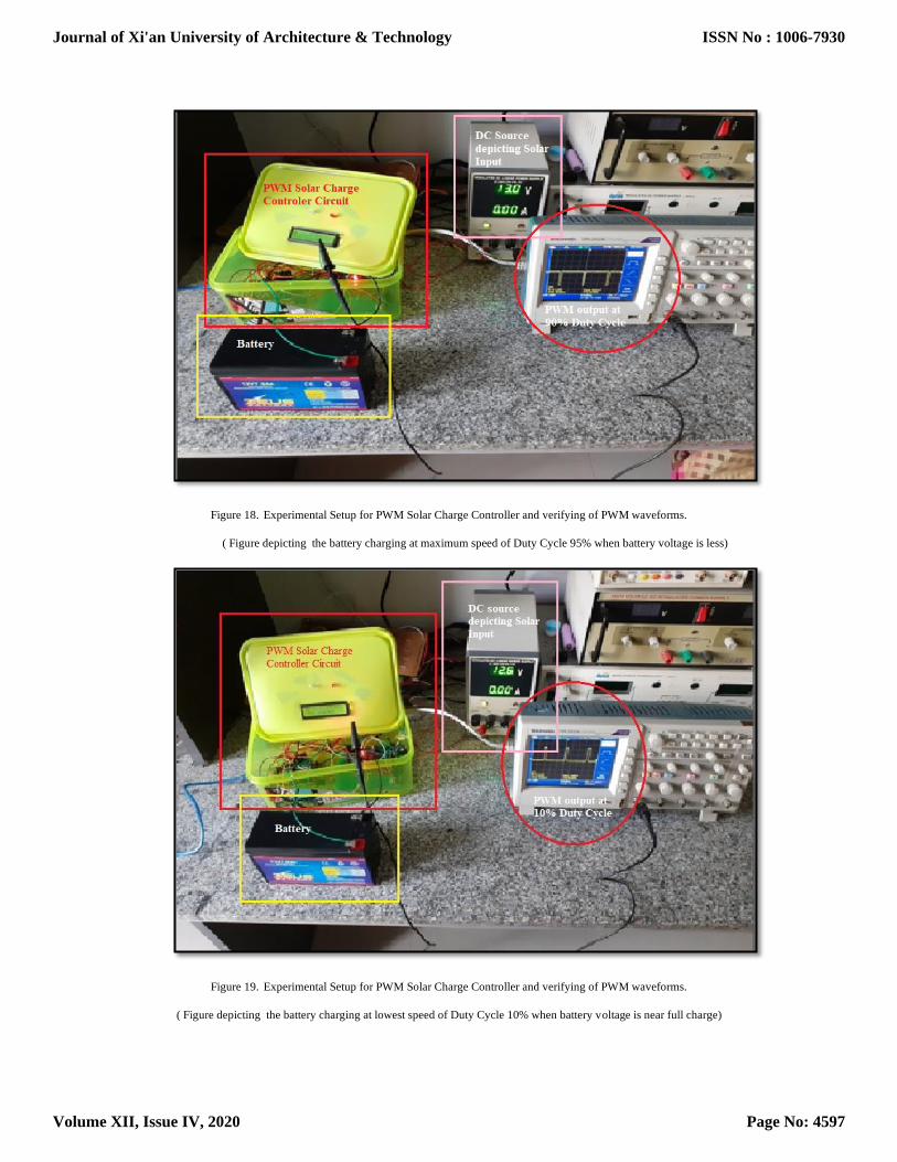
Figure 18. Experimental Setup for PWM Solar Charge Controller and verifying of PWM waveforms.
( Figure depicting the battery charging at maximum speed of Duty Cycle 95% when battery voltage is less)
Figure 19. Experimental Setup for PWM Solar Charge Controller and verifying of PWM waveforms.
( Figure depicting the battery charging at lowest speed of Duty Cycle 10% when battery voltage is near full charge)
Journal of Xi'an University of Architecture & Technology
Volume XII, Issue IV, 2020
ISSN No : 1006-7930
Page No: 4597

V.CONCLUSION
As the demand and awareness for renewable energy is on a rise, the paper presents a new Solar based Automated
Smart Home and Security System. This being achieved by coupling a PWM charge controller along with the solar
panels and using the DTMF technology to satisfactorily control all the home appliances. PWM charge controller has
been used because it is an easy and cost effective solution to many villages in India which are yet to receive the luxury
of electricity. The proposed system not only provides electricity to their home via solar energy but also provides a cheap
and effective module to fulfill the daily demands of the people of the society. It overcomes the drawbacks such as high
cost of PV system as well as the complexity in operation, cost and risk of using conventional switch boards in our home.
REFERENCES
[1] Banerjee, Sudeshna Ghosh; Barnes, Douglas; Singh, Bipul; Mayer, Kristy; Samad, Hussain. 2015. “Power for All: Electricity Access Challenge in India”. World Bank Study. Washington, DC: World Bank. © World Bank.
https://openknowledge.worldbank.org/handle/10986/20525 License: CC BY 3.0 IGO.
[2] Vaishnavi S. Gunge, Pratibha S. Yalagi, “Smart Home Automation: A Literature Review”, IJCA, RTDM 2016.
[3] Bishwajit Swarnakar , Anupama Datta, “Design and Implementation of PWM Charge Controller and Solar Tracking System”, IJSR, Volume
5 Issue 5, May 2016.
[4] CH. Sreeja Reddy , S.Durga Bhavani2, M.Bhavani Marati, C.Divyani , NAGARJUNA.T, “DTMF Modem with Tone Generation and
Detection Using Goertzel Algorithm with MATLAB”, IJCSMC, Vol. 6, Issue.4, April 2017, pg.78 – 89.
Journal of Xi'an University of Architecture & Technology
Volume XII, Issue IV, 2020
ISSN No : 1006-7930
Page No: 4598