Solar Electric Systems Review, Sizing and Component Selection
40
Solar Electric Systems Review, Sizing and Component Selection Presented to SPARCO Technologies SPARCO Technologies
Transcript of Solar Electric Systems Review, Sizing and Component Selection
Solar Electric Systems Review, Sizing and Component Selection
Presented toSPARCO TechnologiesSPARCO Technologies
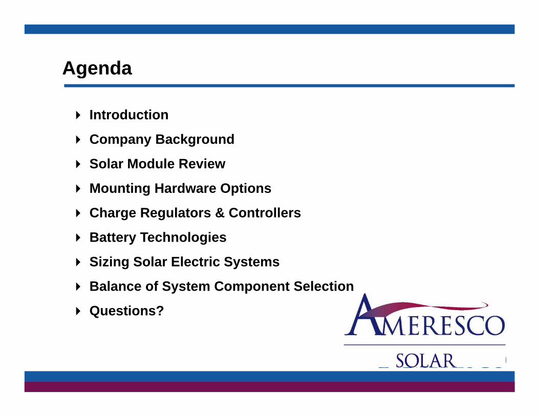
Agendag
Introduction
Company Background
Solar Module Review
Mounting Hardware Options
Charge Regulators & Controllers
B tt T h l iBattery Technologies
Sizing Solar Electric Systems
Balance of System Component SelectionBalance of System Component Selection
Questions?

Ameresco, Inc. is an independent energy solutions companydelivering long-term customer value through
innovative systems strategies and technologyinnovative systems, strategies, and technology.We are the largest, fastest growing, independent
service provider in North America.
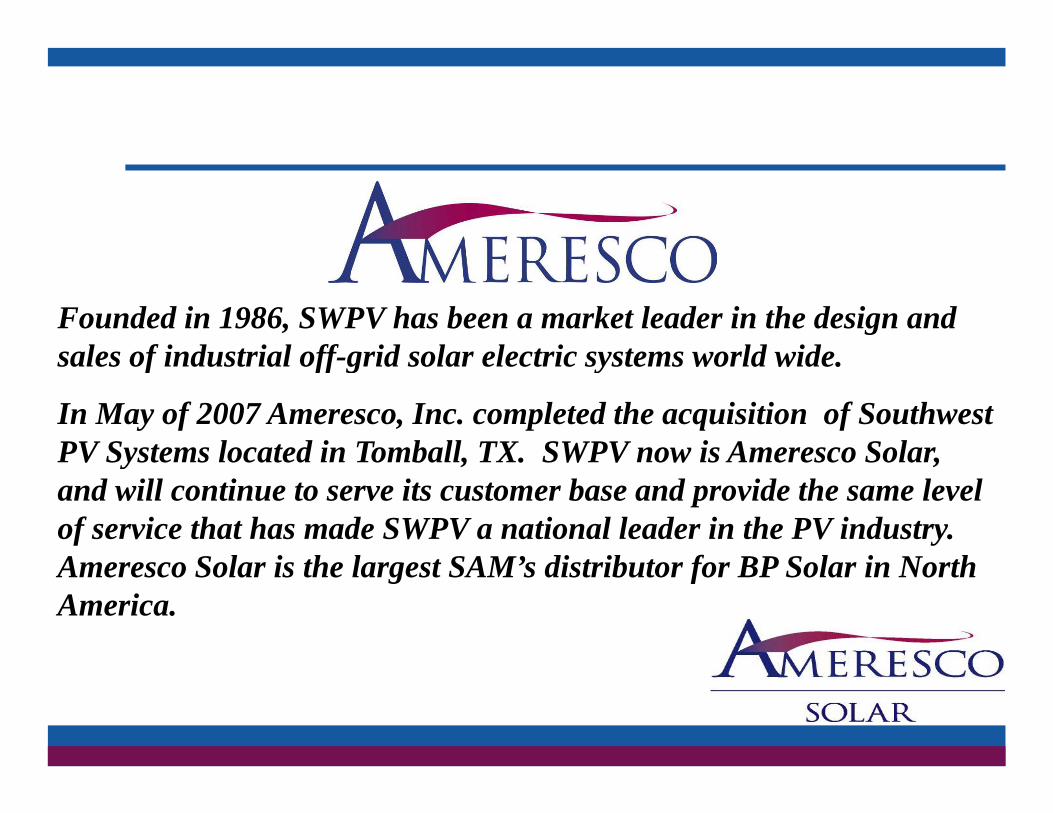
Founded in 1986, SWPV has been a market leader in the design and sales of industrial off grid solar electric systems world widesales of industrial off-grid solar electric systems world wide.
In May of 2007 Ameresco, Inc. completed the acquisition of Southwest PV Systems located in Tomball, TX. SWPV now is Ameresco Solar,PV Systems located in Tomball, TX. SWPV now is Ameresco Solar, and will continue to serve its customer base and provide the same level of service that has made SWPV a national leader in the PV industry. A S l i th l t SAM’ di t ib t f BP S l i N thAmeresco Solar is the largest SAM’s distributor for BP Solar in North America.

Mounting Structures
Roof & Ground Mount
R id RRapid Rac

Solar Module Review
Thin Film
M Si l C t lliMono or Single Crystalline
Poly or Multi Crystalline

Solar Module Review
Thin Film Modules
L f th l t i l t t (2X)− Larger area for the same electrical output (2X)
− Lower efficiency about 7%
Does well in low light levels and off angle radiation− Does well in low light levels and off angle radiation
− Does not perform well in high temperatures
− Lighter weight, no tempered glassLighter weight, no tempered glass
− 6% market share
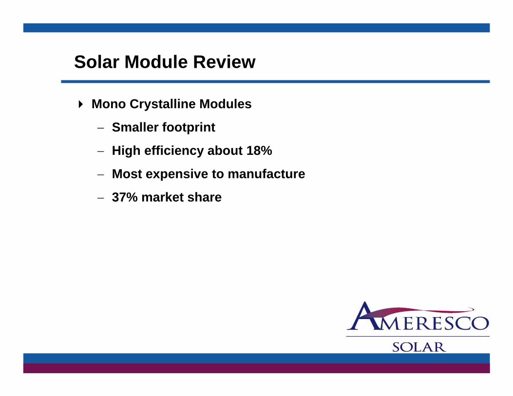
Solar Module Review
Mono Crystalline Modules
S ll f t i t− Smaller footprint
− High efficiency about 18%
Most expensive to manufacture− Most expensive to manufacture
− 37% market share

Solar Module Review
Poly or Multi Crystalline Modules
S ll f t i t th thi fil− Smaller footprint than thin film
− High efficiency about 16%
Not as expensive to manufacture as Mono− Not as expensive to manufacture as Mono
− 57% market share
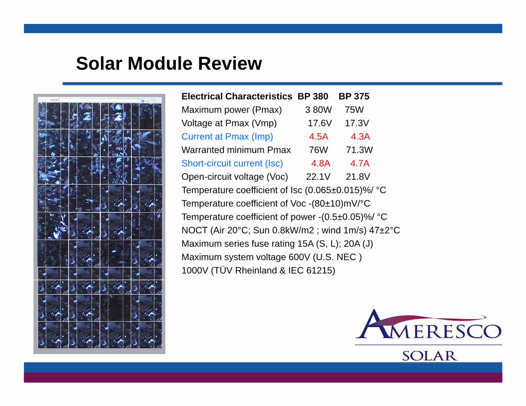
Solar Module ReviewElectrical Characteristics BP 380 BP 375Maximum power (Pmax) 3 80W 75WVoltage at Pmax (Vmp) 17.6V 17.3Vg ( p)Current at Pmax (Imp) 4.5A 4.3AWarranted minimum Pmax 76W 71.3WShort-circuit current (Isc) 4.8A 4.7AOpen-circuit voltage (Voc) 22 1V 21 8VOpen-circuit voltage (Voc) 22.1V 21.8VTemperature coefficient of Isc (0.065±0.015)%/ °CTemperature coefficient of Voc -(80±10)mV/°CTemperature coefficient of power -(0.5±0.05)%/ °CNOCT (Air 20°C; Sun 0 8kW/m2 ; wind 1m/s) 47±2°CNOCT (Air 20°C; Sun 0.8kW/m2 ; wind 1m/s) 47±2°CMaximum series fuse rating 15A (S, L); 20A (J)Maximum system voltage 600V (U.S. NEC )1000V (TÜV Rheinland & IEC 61215)

Solar Module Review
Modules Imp IscNominalvoltage FM/UL
SX305M 0.27 0.3 12VDC Y
SX310J Y
SX310M 0.59 0.69 12VDC Y
SX320J 1.19 1.29 12VDC Y
SX320M 1 19 1 29 12VDC YSX320M 1.19 1.29 12VDC Y
SX330J 1.78 1.94 12VDC Y
SX340J 2.3 2.5 12VDC Y
BP350J 2.9 3.2 12VDC Y
BP365J 3.69 3.99 12VDC YBP365J 3.69 3.99 12VDC Y
BP370J 12VDC Y
BP375J 4.3 4.7 12VDC Y
BP380J 4.5 4.8 12VDC Y
BP3110J 6.5 7.4 12VDC Y
BP3110S 6.5 7.4 12VDC Y
BP3115J 6.7 7.5 12VDC Y
BP3115S 12VDC YBP3115S 12VDC Y
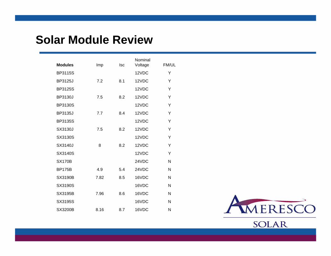
Solar Module Review
Modules Imp IscNominal Voltage FM/UL
BP3115S 12VDC Y
BP3125J 7 2 8 1 12VDC YBP3125J 7.2 8.1 12VDC Y
BP3125S 12VDC Y
BP3130J 7.5 8.2 12VDC Y
BP3130S 12VDC Y
BP3135J 7 7 8 4 12VDC YBP3135J 7.7 8.4 12VDC Y
BP3135S 12VDC Y
SX3130J 7.5 8.2 12VDC Y
SX3130S 12VDC Y
SX3140J 8 8 2 12VDC YSX3140J 8 8.2 12VDC Y
SX3140S 12VDC Y
SX170B 24VDC N
BP175B 4.9 5.4 24VDC N
SX3190B 7 82 8 5 16VDC NSX3190B 7.82 8.5 16VDC N
SX3190S 16VDC N
SX3195B 7.96 8.6 16VDC N
SX3195S 16VDC N
SX3200B 8 16 8 7 16VDC NSX3200B 8.16 8.7 16VDC N

Mounting Structures
Roof & Ground Mount
R id RRapid Rac
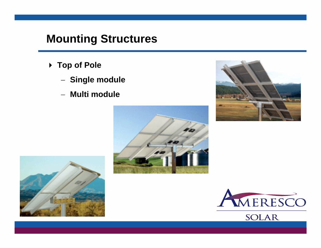
Mounting Structures
Top of Pole
Si l d l− Single module
− Multi module

Mounting Structures
Side of Pole
Si l d l− Single module
− Multi module
Charge Regulators & Controllers
Pulse Width Modulation
Th t ff ti t hi t tThe most effective means to achieve constant voltage battery charging is with a pulse widthmodulated (PWM) control of FET switches in series ( )between the PV array and the battery. This allows for a variable duty cycle that reduces the h i t t i t i t tcharging current as necessary to maintain a constant
voltage at the battery.
Charge Regulators & Controllers
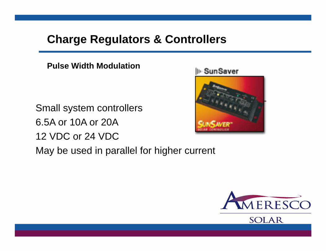
Pulse Width Modulation
Small system controllersSmall system controllers 6.5A or 10A or 20A 12 VDC or 24 VDC May be used in parallel for higher current
Charge Regulators & Controllers
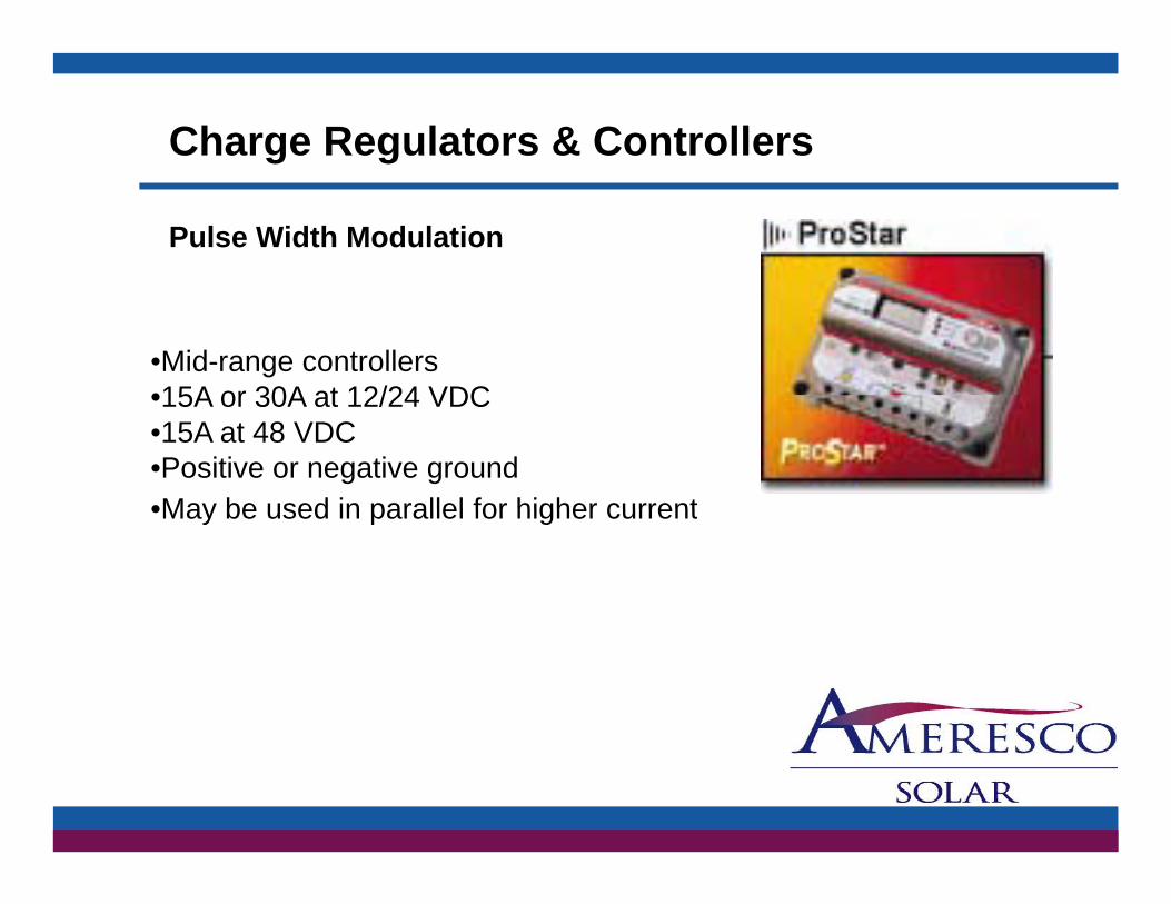
Pulse Width Modulation
•Mid-range controllers •15A or 30A at 12/24 VDC•15A or 30A at 12/24 VDC •15A at 48 VDC •Positive or negative ground •May be used in parallel for higher current•May be used in parallel for higher current

Charge Regulators & Controllers
All of Specialty Concept's solid-state regulators use a modified form of pulse width modulationuse a modified form of pulse-width-modulation (PWM). Instead of a fixed-frequency, variable pulse-width scenario, SCI products use a low-frequency, variable-frequency, variable-pulse-width technology.

Battery Technologies
There are three (3) general types of battery technologies that are used in photovoltaic (PV)technologies that are used in photovoltaic (PV) off-grid application
Flooded
AGMAGM
Gelled
Battery Technologies
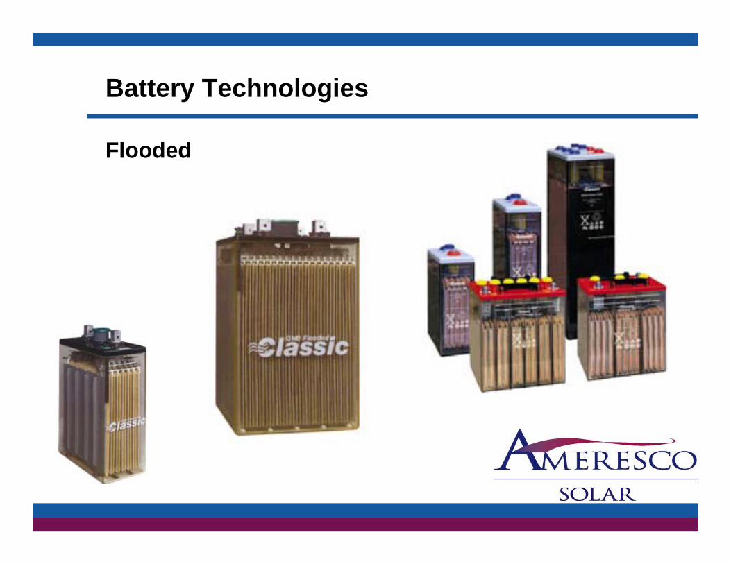
Flooded
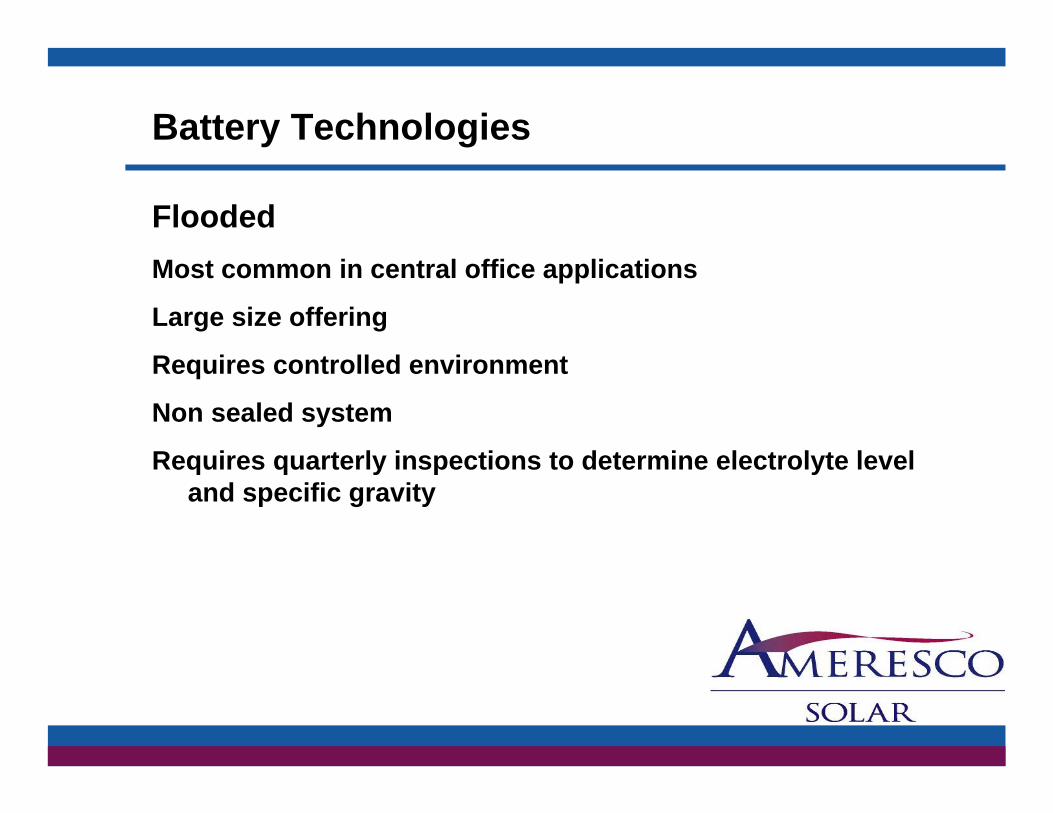
Battery Technologies
FloodedMost common in central office applications
Large size offering
R i t ll d i tRequires controlled environment
Non sealed system
Requires quarterly inspections to determine electrolyte levelRequires quarterly inspections to determine electrolyte level and specific gravity

Battery Technologies
AGM
Battery Technologies
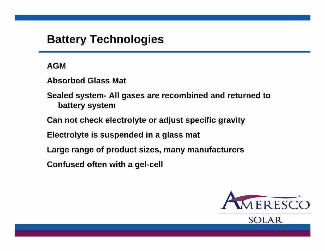
AGM
Ab b d Gl M tAbsorbed Glass Mat
Sealed system- All gases are recombined and returned to battery system
Can not check electrolyte or adjust specific gravity
Electrolyte is suspended in a glass mat
Large range of product sizes, many manufacturers
Confused often with a gel-cell

Battery Technologies
Gelled

Battery Technologies
Gelled
Does depth of discharge affect cycle life?Yes! The harder any battery has to work, the sooner it will fail.* You may experience longer or shorter life based upon application, charging regimen, temperature, rest periods, type of equipment, age of battery, etc.p yp q p g yAs you can see, the shallower the average discharge, the longer the life. This is why it’s important to size a battery system to deliver at least twice the average power required, to assure shallow discharges.Typical* VRLA Battery Cycling Ability vs. Depth of Discharge
Typical Life CyclesCapacity Withdrawn Gel AGM100% 450 15080% 600 20050% 1000 37025% 2100 92510% 5700 3100

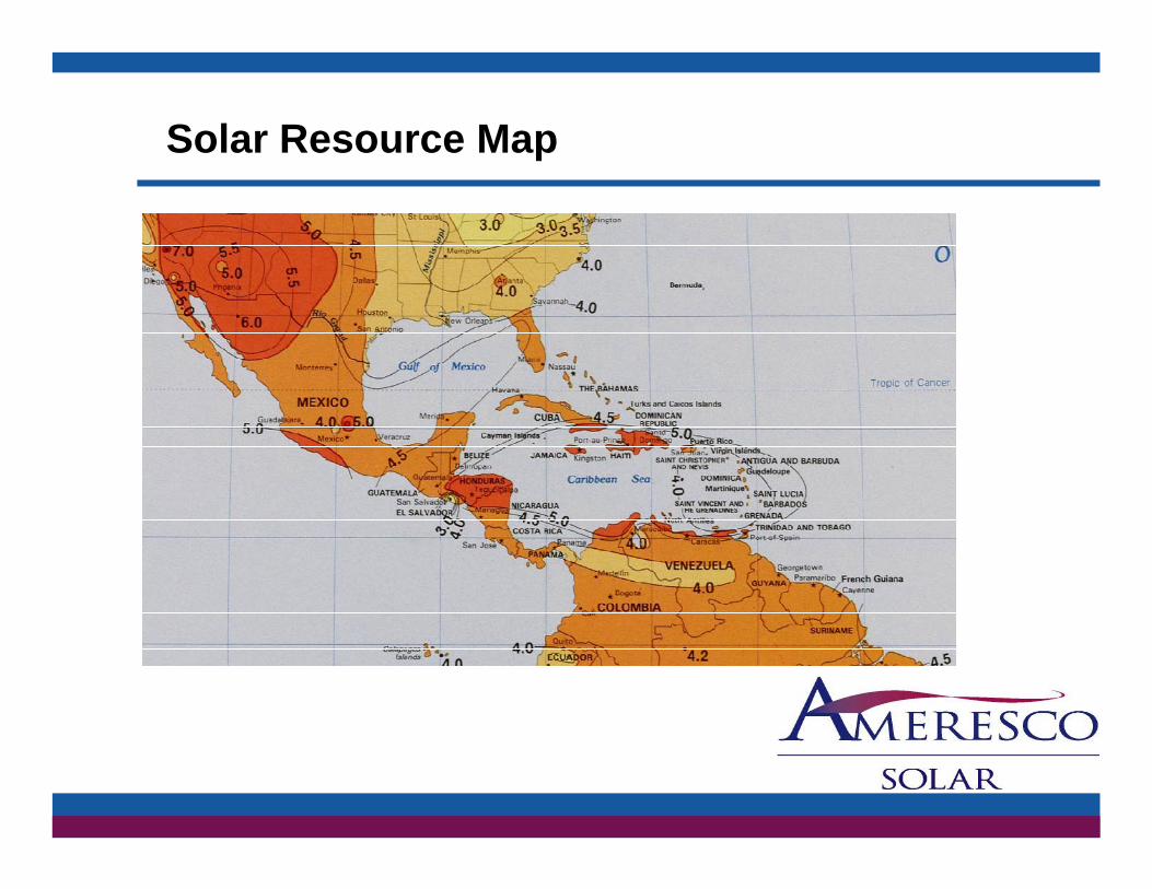
Solar Resource Map
Solar Resource Map

Sizing Solar Arrays
(4) Questions that your customer will be able to provide the answer to:answer to:
1 - What is the power consumption expressed as either watts or amps
2 - Duty-cycle…How long is the equipment running, continuous, intermittent, etc.
3 - What is the equipment voltage, generally but not always3 What is the equipment voltage, generally but not always this is: 12VDC / 24VDC / 48VDC
4 - Where is the geographic location for the system, different locations have different solar resource valueslocations have different solar resource values

Sizing Solar Arrays
(4) Questions that your customer will be able to provide the answer to:answer to:
1-What is the power consumption expressed as either watts or amps
Customer states: I want to power the Cisco 1252 radio that he will purchase from you.
Load = 550 mA or .55 AmpsLoad 550 mA or .55 Amps

Sizing Solar Arrays
(4) Questions that your customer will be able to provide the answer to:provide the answer to:
1-What is the power consumption expressed as either watts or amps 55 Ampseither watts or amps .55 Amps
2-Duty-cycle… continuous, 24 hours
3 Wh t i th i t lt 56VDC3-What is the equipment voltage, 56VDC
4- What is the geographic location for the system,
San Antonio, TX = 4.5 ESH (Equivalent Sun hours)

Sizing Solar Arrays
Load Calculations
.55A x 24 hrs = 13.2 Amp Hours
Add Service Factor of 1.2
13.2 x 1.2 = 15.84 Amp Hours
Divide by .85 for DC to DC converter efficiencyy y
15.84 / .85 = 18.64 Total Amp Hours Adjusted
Sizing Solar Arrays
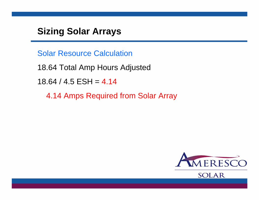
Solar Resource Calculation
18.64 Total Amp Hours Adjusted
18.64 / 4.5 ESH = 4.14
4.14 Amps Required from Solar Array

Sizing Solar Arrays
Solar Module Selection Calculation
4.14 Amps Required from Solar Array
4.14 / 4.12 (BP SX375 Pmax) = 1.00
1 – BP SX375, 75 Watt Peak module will match the power requirement based on the ESH of 4.5 or
tgreater
Sizing Solar Arrays
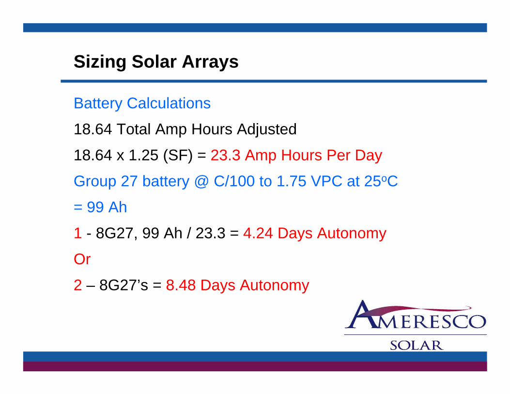
Battery Calculations
18.64 Total Amp Hours Adjusted
18.64 x 1.25 (SF) = 23.3 Amp Hours Per Day
Group 27 battery @ C/100 to 1.75 VPC at 25oC
= 99 Ah
1 - 8G27, 99 Ah / 23.3 = 4.24 Days Autonomy
Or
2 – 8G27’s = 8.48 Days Autonomy
Sizing Solar Arrays
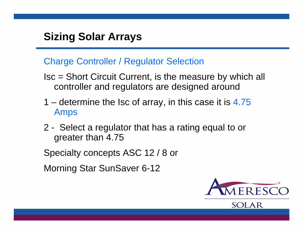
Charge Controller / Regulator Selection
Isc = Short Circuit Current, is the measure by which all controller and regulators are designed around
1 determine the Isc of array in this case it is 4 751 – determine the Isc of array, in this case it is 4.75 Amps
2 - Select a regulator that has a rating equal to or g g qgreater than 4.75
Specialty concepts ASC 12 / 8 or
Morning Star SunSaver 6-12

Sizing Solar Arrays
Bill of MaterialsQty DescriptionQty Description
1 BP SX 375 Solar module, 75 watts peak
1 Side of Pole mount for single module SPM1
1 Out put cable #10-2 x 15’ with fork terminals and strain relief
1 Charge regulator model SS6-12
1 Regulator to battery cable with ring and fork terminalsg y g
1 8G27, 99 Ahs @c/100 yielding 4.24 days autonomy
1 Aluminum back plate integrated w/terminal stripe, breakers & regulator
1 BBA 1 aluminum battery enclosure1 BBA-1, aluminum battery enclosure

Sizing Solar Arrays
New Sizing
Load: 1.5 Amps
Duty-cycle: continuous
Voltage: 56VDC
Geographic Location: Pittsburgh, PA w/ 2.0 ESHg p g ,

Sizing Solar Arrays
1.5 amps x 1.2 (SF) / .85 (converter Eff.) x 24 = 50.83 Ah Adj.
50 83 / 2 (ESH) 25 41 A R i d f A50.83 / 2 (ESH) = 25.41 Amps Required from Array
25.41/ 6.5 (BP 3110, 6.5 Pmax 110 watt) = 3.91 or 4 modules
50.83 x 1.25 (SF) = 63.54 Ah per day
99/63 54 = 1 56 days autonomy99/63.54 1.56 days autonomy
265Ah / 63.54 = 4.17 days autonomy
2- 265Ah / 63.54 = 8.34 days autonomyy y
Sizing Solar Arrays
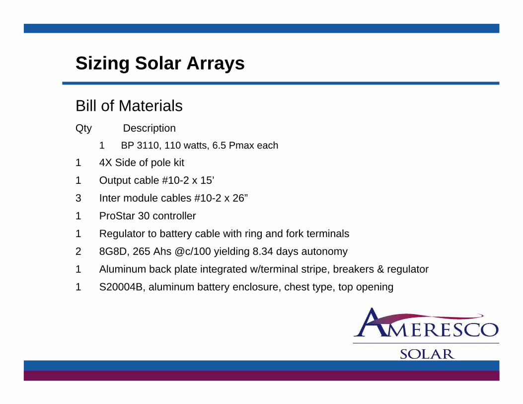
Bill of MaterialsQt D i tiQty Description
1 BP 3110, 110 watts, 6.5 Pmax each
1 4X Side of pole kit
1 O t t bl #10 2 15’1 Output cable #10-2 x 15’
3 Inter module cables #10-2 x 26”
1 ProStar 30 controller
1 Regulator to battery cable with ring and fork terminals
2 8G8D, 265 Ahs @c/100 yielding 8.34 days autonomy
1 Aluminum back plate integrated w/terminal stripe, breakers & regulator
1 S20004B, aluminum battery enclosure, chest type, top opening