AFT Evaluating Pipe Dynamic Loads Caused by Waterhammer 01-02-2013 SI

SOLAR DYNAMIC HEAT PIPE DEVELOPMENT - AND ENDURANCE TEST
CONTRACT NO. 9 - X6H - 8102L - 1 MONTHLY TECHNICAL PROGRESS REPORT NO. 3
28 JULY TO 27 AUGUST 1987
PREPARED FOR LOS ALAMOS NATIONAL LABORATORY LOS ALAMOS, NEW MEXICO 87545
PREPARED BY: 03,87 I
L
APPROVED BY: ENREICH) PROGRAM MANAGER
TION MANAGER
(R. RUDEY) 'ENGINE -

DISCLAIMER
This report was prepared as an account of work sponsored by an agency of the United States Government. Neither the United States Government nor any agency thereof, nor any of their employees, makes any warranty, express or implied, or assumes any legal liability or responsibility for the accuracy, completeness, or use- fulness of any information, apparatus, product, or process disclosed, or represents that its use would not infringe privately owned rights. Reference herein to any spc- cific commercial product, process, or service by trade name, trademark, manufac- turer, or otherwise does not necessarily constitute or imply its endorsement, recom- mendktion, or favoring by the United States Government or any agency thereof. The views and opinions of authors expressed herein do not necessarily state or reflect those of the United States Government or any agency thereof.
I. Introduction
The Space Station requires a high level of reliable electric power. in which power is provided by phofovoltaic arrays and by solar dynamic power conversion modules. The organic Rankine cycle (ORC) engine is one approach to solar dynamic conversion. The ORC provides the attributes of high efficiency at low temperature and compact simple designs utilizing conventional techniques and materials. receiver is one area which must be addressed in applying the proven ORC to long life applications such as the Space Station. Heat pipes with integral thermal energy storage (TES) canisters and a toluene heater tube are the prime components of the heat receiver from the Phase B preliminary design. This contract is a task order type addressing the design, fabrication and testing of a full scale heat pipe. The contract was initiated on April 16, 1987. Sundstrand has specific responsibilities in each task. Los Alamos National Laboratory (LANL) in turn has the prime contract responsibility to NASA-LeRC.
The baseline approach is to utilize a hybrid system
The heat
Task No. 1 - Transient Tests with the Phase B Heat Pipe The objective of these tests is the determination of the operating characteristics and power input limits of the heat pipe under conditions corresponding to reacquisition of the sun during emergence from eclipse or conditions corresponding to initial startup of the solar dynamic power system. contract NAS3-24666 will be used for these tests;- The tests will be conducted by LANL in 9 vacuum test facility. After completion of these tests, the heat pipe is to be disassembled, inspected and analyzed. Sundstrand's responsibilities for Task 1 are:
The heat pipe designed and fabricated under NASA
1. 2. 3. 4.
Review LANL test plans. Witness (at our option) and analyze all tests. Witness disassembly of the heat pipe. Upon receipt of the canisters from the disassembled heat pipe, perform chemical and metallurgical analysis on the canisters and LiOH salt.
Task 2 - New Heat Pipe Design Fabrication and Testing The objective of this task is to design, fabricate and performance test a new heat pipe with thermal energy storage and a simulated toluene heater. Structural analysis and a random vibration test of the complete assembly are to be performed. conducted before and after the dynamic testing. Sundstrand's responsibilities for Task 2 are:
Performance characterization by test is to be

Task
1.
2. 3 .
4 .
5.
6.
3 -
Design and fabricate flight weight thermal energy storage canisters with a thermocouple well to allow for monitoring the phase change material temperature during testing. Review LANL's heat pipe'analyses and test plans. Develop specifications of input heat flux and design vibration spectrum. Design, fabricate, analyze and checkout vibration test fixture. Perform a random vibration test in each of three mutually orthogonal axes. Witness and analyze heat pipe performance tests conducted by LANL.
Endurance Testing
The objectives of this task is to perform a six-month continuous thermal cycling test of the new heat pipe with TES charge and discharge cycles corresponding to a typical space station orbital cycle. Post test physical, chemical and metallurgical analysis of the heat pipe assembly is to be performed. Sundstrand's responsibilities for Task 3 are:
1. Review LANL instrumentation, test plans and test
2. Perform post-test chemical and metallurgical data.
analyses on the canisters and LiOH.
Task 4 - Toluene Heater Tube The objectives of this task, to be performed solely by Sundstrand are:
1. Design and fabricate a supercritical reverse flow heater for use with toluene.
2. Modify an existing toluene flow facility to accommodate testing and characterization of the toluene heater.
3 . Perform a series of tests to determine the heat transfer and flow characteristics of the toluene heater.
Task 5 - Reporting
Sundstrand's responsibilities are:
1. Prior to the initiation of any testing, submit a test plan for the approval of the LANL Project Manager.
2. Support LANL at oral briefings at LeRC or a location to be specified by the LANL Project Manager.
3 . Provide ( 8 ) copies of a written final report giving each task objective, approach, design, fabrication and testing details to LANL at the completion of the total program.

11. Technical Progress
Overview
This report covers 1987. The primary
Summary
the period from 28 July to 27 August, activities were the fabrication of three ~ ~ _ _
7 4 . 4 inch long Li6H canisters and a 72-inch long toluene heater tube. National Lab on August 20, 1987. Additional activities related to the heat pipe vibration fixture are also in progress. and milestones.
The LiOH canisters were received by Los Alamos
Figure 1 shows the Sundstrand program schedule
Task 1 - Transient Tests on the Existing Phase B Heat Pipe Transient tests on the Phase B heat pipe were completed and the test results review was reported in the monthly technical progress report no. 1.
A test plan for an additional test was prepared by LANL to measure the hydrogen permeation through the Phase B heat pipe wall. being reviewed by Sundstrand. test plan will be transmitted to LANL in the first week of September 1987.
A copy of the test plan was received and is The technical comments on the
Task 2 - New Heat Pipe Design, Fabrication and Testing Thermal Energy Storage Canisters:
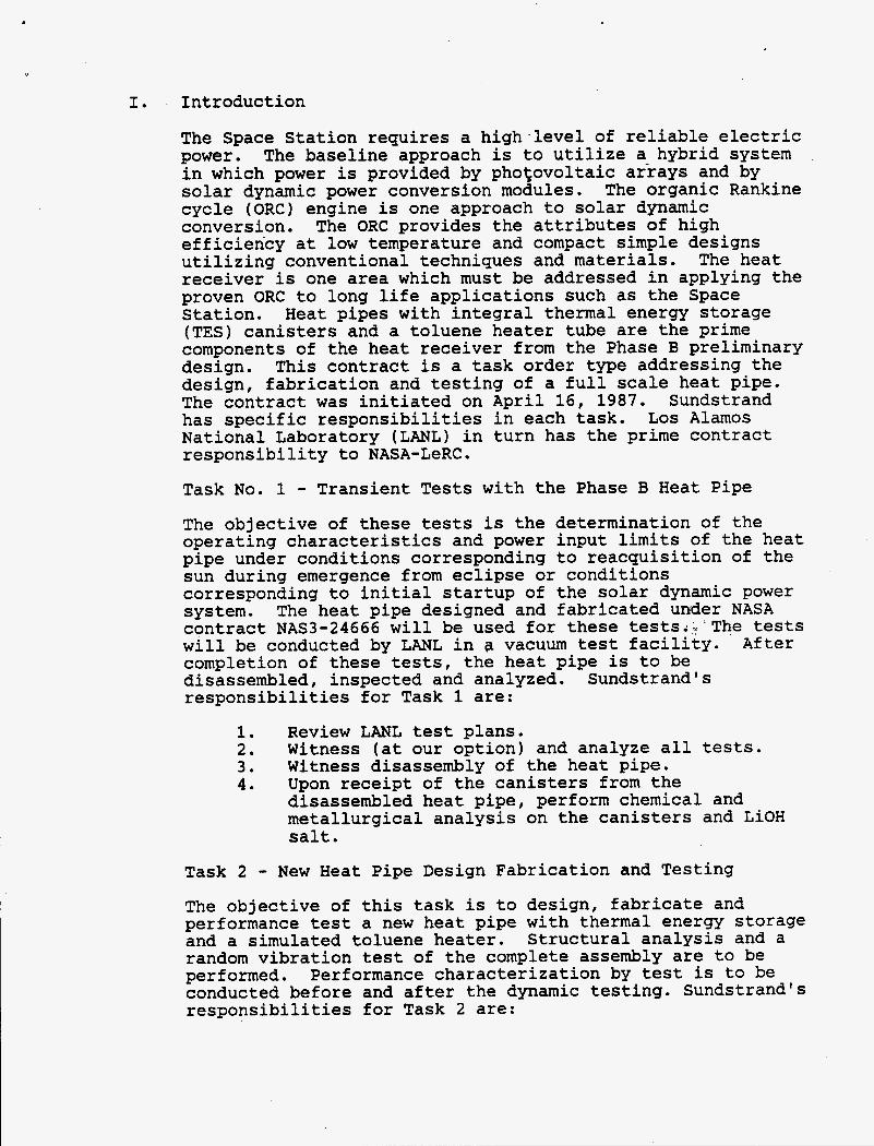
Six (6) Ni-201 cases filled with Ni-201 fins and LiOH, vacuum baked and sealed in moi,sture proof bags, were shipped to the vendor for the final electron beam (EB) welding operations. shown in Figure 2. After successful completion of the secondary seal EB weld operation, the necessary weld preparation and cleaning operations were performed on the mating cases. Three sets of mating cases were EB welded which resulted into three ( 3 ) full size ( 7 4 . 4 inch long) LiOH TES canisters (See Figures 2 and 3 ) . The final radiographic examination of these weld joints were performed by an independent inspection laboratory. The weld joints met the NAS 1514 Class I (highest class) requirements. All three canisters were received by LANL on August 20, 1987. Figure 4 provides the weight summary of three LiOH canisters. A detailed fabrication procedure report of this process will be prepared during the next reporting period.
A secondary seal was EB welded to each case as
Heat Pipe Vibration
A schematic describing the vibration fixture is shown in Figure 5. begun. reported next month.
The vibration fixture design activities were just The detailed vibration fixture design will be

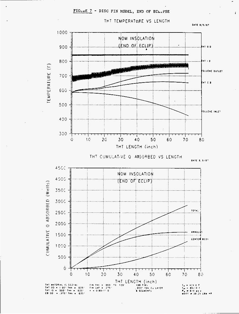
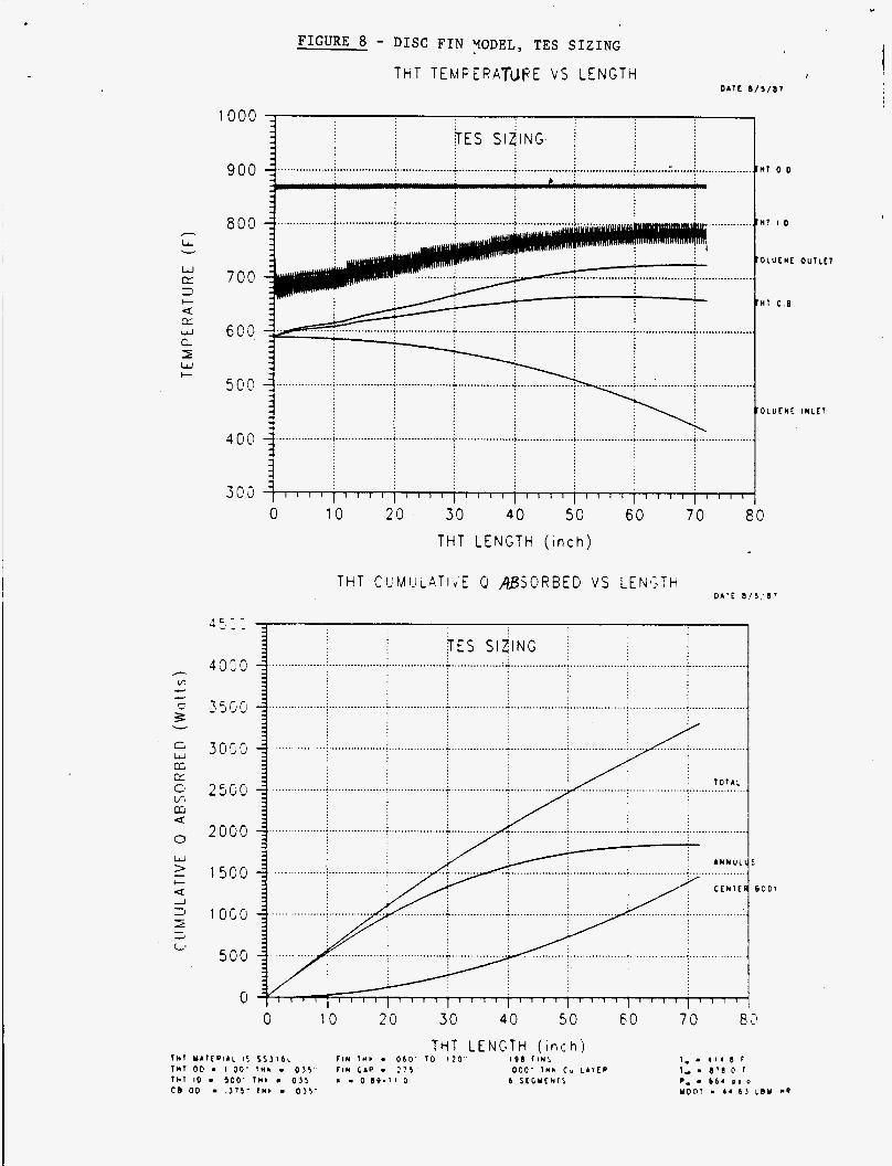
Task 4 - Toluene Heater Tube (THT) Thermal Analysis
A thermal standoff provides varying thermal resistance between the outer tube heat input and the working fluid flowing through the center tube. were analyzed, a disc fin design (Figure 12) and a longitudinal fin design (Figure 11).
b
Two different geometries
Disc Fin Model
The conditions of (1) end of insolation, (2) end of eclipse, ( 3 ) TES sizing, and (4) maximum insolation were run using the disc fin model. achieved by solving all fluid nodes and center body temperatures in a subroutine separate from SINDA. Results are presented in Figures 6 through 9.
An improvement in convergence was
The THT design being fabricated is slightly different from the preliminary design for the THT described above. Minor modifications of the computer input data (fin thickness, spacing, number of fins, etc.) enabled the fabrication design geometry to be considered. The results of the analysis are presented in Figure 10. A reduction in the fin gap from .275 to .195 decreases &he temperature differential between fins to approximately 20 F.
Lonqitudinal Fin Model
The thermal analysis of the longitudinal fin concept resulted in a geometry shown in Figure 11. fabricate this design. No further thermal model analysis is planned until the disc fin heater tube is performance tested and the test results are compared with the disc fin math model.
The plan is to
Fabrication:
Disc Fin Desiqn
The necessary raw materials for the fabrication of the 72-inch prototype was procured. The thermal standoff assemblies are shown in Figures 12 and 13. The heater tube consists of seven thermal standoff assemblies having different thermal resistances. The fin thickness, spacing and number of fins for each thermal standoff assembly is described in Figure 14. These thermal standoff assemblies are in the brazing process for joining the fins and 1.000 dia. tube. The parts will be radiographically

examined after completion of the brazing operation. principal manufacturing operations prior to completion of the 72-inch prototype heater tuba include gun drilling, welding, radiographic/ultrasonic, proof pressure and helium leak check. heater tube is October 15, 1987.
The
The schedule delivery date for the disc fin
Longitudinal Fin Design
The .375, .500 and 1.000 dia. SS 316L tubes were procured for the longitudinal fin heater tube. for the fins are ordered and scheduled to be received the first week of September 1987.
The strip materials
The cross sectional examination of the braze samples received from the brazing vendor was completed and the results were presented in reference 1. The vendor was requested to provide process improvement corrective actions. The fabrication of the 72-inch long longitudinal fin heater tube will proceed as soon as the vendor quotes are received and reviewed.
Toluene Heater Tube Test Facility
Sundstrand received an authorization on July 29, 1987 from LANL to utilize the existing toluene stability test facility. The removal of salt bath from the existing test facility is in progress. The horizontal fluidized bed required as a heat source for the toluene heater tube test was ordered on July 31, 1987. The scheduled delivery date for the fluidized bed is September 30, 1987.
Proqram
The actual cumulative expenditures through August 15, 1987 are $225,615.00.
Work Planned for the Next Reportinq Period
Task 2
0 Complete heat pipe vibration fixture design
Task 4
0 Fabricate full size longitudinal fin and disk fin heater tubes.
o Add bypass system on the therminol heat exchanger of the test facility
0 Receive fluidized bed

Reference:
1. 9-X6H-8102L-l - Solar Dynamic Heat Pipe De-dopment and Endurance Test Monthly Technical Progress Report No. 2, dated July 27, 1987. b

0
\
I + .020
J r ~ o o 3 ~ L ~ O 0 REF -500 -.ooo 4
.'
*-- JT 2.100 i
t t
+ .ooo .500 - .020 DIA
7 - - - 73.400 REF
----
.500 -- 500 .600
6 FINS/IN. ( .
i- .- t t /
I + .020 -500 -.ooo
.'
*-- JT 2.100 i
+ .ooo .500 - .020 DIA
7 73.400 REF
36.700 REF ----
3.500 REF 1 .600
6 FINS/IN. ( .
.500 jF \ i- .-
+ .004 I
*050 -.001 L SECONDARY L O I D SEAL ( T Y P . 2)
F I G U R E 2 - THERMAL ENERGY STORAGE CANISTER INTERFACE DRAWING
1 I FIGURE 3
SUNDSTRAND 6-FT TES CANISTER (Ni-ZOl/LIOH) I
I

S/N NO. OF FINS
FIGURE 4
TES CANISTER WEIGHT SUMMARY
LiOH WEIGHT (GMS) TOTAL WEIGHT (GMS)
001
002
003
425
428
425
4610 (10.15 LBS)
4630 (10.20 LBS)
4626 (10.19 LBS)
11,656 (25.67 LBS)
11,333 (24.96 LBS)
11,387 (25.08 LBS)

I .
P .r
..; . '), . '
, . i '
. . . I . . _ . .
.. , ,
. .
. .
. .
, I . . ' I .
c . . ... . 1 ' , .. , . t ' I
'. . . ,
1 . . .
I , . :
8 i
-. .
W a a w
X
H
2
i
' .
. .
. . i .
. I
..
. i 1 ' . 4 .'I
i ,: ' k

FIGb..E 6 - DISC FIN MODEL, END OF Z N b d ~ A T I O N -- T H T T E M P E R A T U R E V S L E N G T H
NOM I N S ~ O L A T I O ~ . .
.................. ................ ................... .............. : E N D .... O.F-.~..INS.O.L~ .........._...... :i I * j
D A T E 8 / 4 / 8 7
1000
.................. ................... i .................. ................... .................... i ; I .... ................ I...... .......................... ,.
I 1 , # I I 1 1 , I , ( , I l l 1 1 1 1
60 7 0 8 0 2 0 30 40 50 0 10
T H T L E N G T H ( i n c h )
THT C U M U L A T I V E 0 A B S O R B E D V S L E N G T H D A T E 8 4 . ' 8 -
................. ................................... .... ................... i or..i.Ns.DLj : ................... ................. N O M I N ~ ~ L O A T I O ~
.................. ..................................... ............... .............. ................. .......... i.... + .i 1 ~
.................. .................. ................ ................. .................. ......... -..- .................................. : ~ . . . . i - j
2500
2000
1500
1oocl
5 0 0
0
.................. : ..................................
................ ............. : ..................
................................................
.................................... / ...../ C E N T I
........... .................. .................. ................. : i
10 LU 3 0 40 0 50 6 0 70 82
C . B
8 3 0 ,
h
L u
W IT 3
IT W Q I W
t a
L
FIGbnE 7 - DISC F I N MODEL, END OF ECLLPSE
THT TEMPERATURE V S L E N G T H D A T E 8 / 5 / 8 7
1000
900
800
700
600
500
400
300
I .................. .................. ................ .... .................. .................. H I o o
I I
t 1 1 1 1 1 I 1 I I I I I I I
0 I 0 2C 30 40 50 60 7 0 8G T H T L E N G T H ( i n c h )
D A T E I 5 / c - THT C U M U L A T I V E 0 ABSOREEP V S L E N G T H
N 0 M I 11 Si0 L AT I 0 ......... .................... ....................................................... .( ~ . N .tj.. .o' , . "E %"L i'p 'si..
........................................................ -. ............... .........................................................
................................. - ................. - ............................................................................
0 10 20 30 40 5 0 60 7 0 THT L E N G T H f i n c h )
I , . * :4 0 r I, . 0 5 : 0 f P. 614 o s i o Y D O l J O 2 5 L B Y w e
O U T L E l
I N L E T
e
- cn
‘= e e
a v
c W a
L’
1000
900
8 0 0
700
6011
5@?
400
303
FIGURE 8 - D I S C F I N YODEL, TES SIZING
THT T E M F E R A T U F E V S L E N G T H I
D A T E 8 / 5 / 8 7
.............
0 10 20 30 4 0 5 0 60 7 0 80 THT L E N G T H ( i n c h )
$ES S I ~ I N G ................. : .................. ; .................. L ................. . . : .................. : .................. : ..................
3059
2000
1500
1 O G O
500
Hl 0 D
H l I D
O L U f Y E O U I L f l
O L U E N E I N L E T
5
B O D 1
0 10 20 30 40 50 60 70 8 ;’
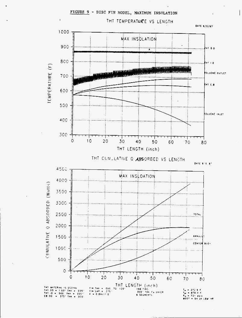
FIGURE 9 - DISC FIN MODEL, MAXIMUM INSOLATION I THT TEMPERATUfE V S L E N G T H
700
600
O D
UT I O
O L U E N E O U T L E T
H T C . B
) L U E U E I N L E T :\ . .......... .. . ................ 4 .................. < ................... ~ ..................................... ' .._.......... ...(__.._.__......
I
10 20 30 40 50 60 70 80 THT L E N G T H ( i n c h )
THT CIJFwI.tLATIVE 0 A S O R G E D V S L E N i T H D A T E 8 5 8 -
4000
350Cl
3000
2 5 0 0
2000
1500
1 O G C
500
0
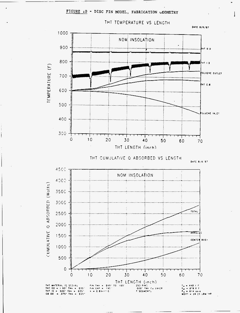
FIGURE 10 - DISC FIN MODEL, FABRICATION GEOMETRY
h
LL L
w tr 3 t a CL w a I W c
w > - c a
THT T E M F E R A T U R E V S L E N G T H D A T E 8 / 6 / 8 7
O L U E U E O U l t E l
T H T L E N G T H f i n c h )
D A T E 0 / 6 , ' 8 7
..
3900
2500
2005
1509
1009
500
0
i N O M I N S O L A T I O N .................... .................... ................... ............... .................... .... : ..................... : 1 ..................... - -
................... ................... .................... .................... .................... :- 4 1 1 ......................................... 1
0 10 20 3'0 40 50 60 70

ii 5 k

!
i
4
k
I
i 7
L
.+ i, !
L
d
''1

, . ,. . + , .
. . , .
I .
5
F I G U R E 13
THERMAL STANDOFF ASSEMBLY ( T H I N AND THICK D I S C F I N S )
n

4
FIGURE 14
THERMAL STANDOFF ASSEMBLY (DISC FIN HEATER TUBE)
b
DASH NO.
R1
R2
R3
R4
R5
R6
R7
FIN SPACING FIN THICKNESS NO. OF FINS ( INCHES) ( INCHES )
.I95 .040 42
.195 .OS0 41
.195
.195
.060
.070
40
38
.195 .080 37
.195
.195
.090
. l o o 35
22

SUNDSTRAND ADVANCU) TECHNOLOGY OPERATIONS
MONTHLY F I NANCI AL MANAGEMENT REPORT
PROGRAM : SPACE STATION HEAT PIPE DEVELOPMENT
LOS ALAMOS NATIONAL LABORATORY
CONTRACT : 9 - X 6 H - 8 1 0 2 L - l
REPORT SUBMITTAL: September 8, 1987
August ACTUALS THROUGH :
PREPARED BY
APPROVED BY
DISK:CMA4 CMA-00159

J

Pa6E_-1-- DF_--Z--- . __-____-___ __----______(
REPORT FOR RONTH END HONTHLY CONTRACTOR FINANCIAL HANAGEHENT REPORT AUGUST 28, 1987
; :TO: UNIVERSITY OF CALIFORNIA : FROM: SUNDSTRdNO CORPORATION CONTRACT VALUE I LOS BLAH05 NATIONAL LABORATORY AVlbTlON D lV lS lOH : P.O. BOX 990 4747 HIIRRISON AVENUE : COSTS: : FEE: I
I LOS ALAHOS. 1.11. 87544-0990 RKYFMID, I L L l N O l S 61125 10 $0
: TYPE: : CONTRRCT NO. k DEFlN l I lZED AHEWOHENT NO. FUND L lH ITAT lON . : DESCRIPTION : COST PLUS FIXED FEE 9-X6H-8102L-I LETTER DATED: 61 12/87 $400,000
OF I CONTRACT
I REPORTING CATEGORY
I SUHHARV BY
: COST CATAGORIES:
c

M98005269 I lllllll! Ill lllll1111111111111ll lllll Ill11 ll!llllll1111
Publ. Date (11) 19g7 0 4 a 3 Sponsor Code (18) DoD 1
I
19980706 012
DOE