Solar Driven H 2 O/CO 2 Splitting via Thermochemical Cycles
27
Sandia is a multiprogram laboratory operated by Sandia Corporation, a Lockheed Martin Company, for the United States Department of Energy’s National Nuclear Security Administration under contract DE-AC04-94AL85000. Solar Driven H 2 O/CO 2 Splitting via Thermochemical Cycles Presented by Richard B. Diver May 4, 2010
Transcript of Solar Driven H 2 O/CO 2 Splitting via Thermochemical Cycles

Sandia is a multiprogram laboratory operated by Sandia Corporation, a Lockheed Martin Company,for the United States Department of Energy’s National Nuclear Security Administration
under contract DE-AC04-94AL85000.
Solar Driven H2O/CO2
Splitting via Thermochemical Cycles
Presented by Richard B. Diver
May 4, 2010
Funding – Sandia Laboratory Directed Research and DevelopmentPrincipal Investigator – James E. MillerProject Manager - Ellen B. StechelSystems Daniel Dedrick, Terry Johnson, Chad Staiger, Greg Evans, Josh Deetz
(student intern,) Christos Maravelias (U-WI), Carlos Henao (student,) Jiyong Kim (PD)
Reactor Solar Reactor - Rich Diver, Nathan Siegel, Tim Moss, D. Ray, John Kelton, Reactive Structures - Nathan Siegel, Terry Garino, Nelson Bell Detailed Reactor Models - Roy Hogan, Ken Chen, Bob Podgurski, Darryl
James (TTU,) Luke Mayer (student)Materials Reactive Materials Characterization & Development - Andrea Ambrosini, Eric
Coker, Mark Rodriguez, Stephanie Livers, Lindsey Evans Bulk Transport & Surface Reactions - Gary Kellogg, Ivan Ermanoski, Taisuke
Ohta, Randy Creighton Thermodynamics & Reaction Kinetics - Mark Allendorf, Tony McDaniel, Chris
Wolverton (Northwestern University), Bryce Meredig (student), Heine Hansen (PD), Al Weimer (CU,) Jon Scheffe (student)
S2P Project Elements and Team

Incorporating CO2 into the Hydrogen Economy captures the benefits of hydrogen while preserving the advantages of the Hydrocarbon Economy.
Vision: Directly apply a solar thermal energy source to effectively reverse combustion and “energize” CO2 and H2O into hydrocarbon form in a process analogous to, but more efficient than, the one that produces bio- and fossil fuels.
Sunshine to Petrol
Energy Input(Reduction)
CO2H2O Fuel
O2
Energy Recovery(Oxidation/combustion)
Sunlight + CO2 + H2O → Fuel + O2
“Beyond Hydrogen”

OV - 4OV - 4
For now and for transportation fuels, liquid hydrocarbons are the “Gold Standard”
OV - 4OV - 4
Hydrocarbons are the Ultimate for Large Scale/Long Term Energy Storage
• Energy Density• Infrastructure• Fueling Rate• Airplanes • Heavy Vehicles• etc.
FuelEnergy per Unit Mass
Energy per Unit Volume
Gasoline 1 1JP-5 0.97 1.1Methanol 0.44 0.51Ethanol 0.61 0.69Liquid H2 (-253°C) 2.6 0.27Metal Hydride 0.046 0.36Methane @ 3000 psi 1.1 0.29H2 gas @ 3000 psi 2.6 0.06Liquid Propane @ 125 psi 1 0.86Methane @ 10000 psi 1.1 0.97H2 gas @ 10000 psi 2.6 0.2Lithium Ion Battery 0.019 0.035

Direct Chemical Routes?
CO + 2H2 → CH3OH → C2H6O(DME) + H2OCapitalize on decades of Synfuel technology, e.g.
Note that WS and CDS are linked by the Water Gas Shift reaction
CO + H2O ↔ CO2 + H2
We are only required to carry out one reaction - WS or CDS
4H2O + energy → 4H2 + 2O2 (water splitting)2CO2 + energy → 2CO + O2 (carbon dioxide splitting)
2CO2 + 4H2O + energy → 2CO + 4H2 + 3O2
Focus on the following critical conversions:

Energy Efficiency (sunlight to fuel) is a key consideration
Nominal Equivalent Land Area Required to Produce 20 mbpd at a given efficiency.
Sunlight to fuel efficiency assuming solar resource equivalent to Albuquerque – 2600 kWh/m2/yr.
U.S. Petroleum consumption - 20 million bbls/day
100% - Delaware10% - NJ + MA
3% - Georgia
0.1% - Western U.S.
Fossil oil ~ 2x1 0- 4
Bioethanol routes currently < 1 %.Photosynthesis < 6% (Theoretical)
Photosynthesis < 0. 5% (actual, large area crops)

Electrochemistry Sets the Standard for Efficiency
PV powered Electrolysis
Electrical (%)
H2
(%)Conversion to
Fuel (%)
Sun to Fuel(%)
Efficiency 10-15 75 40-50(1)
50(2)~ 3-6 (?)
Limiting factors include photon to electric conversion and
unfavorable thermodynamics for the reaction of H2 and CO2.
WGS Reaction of CO2 and H2requires additional energy input.
CO + H2O = CO2 + H2
Temperature (°C)0 200 400 600 800 1000 1200 1400
Equ
ilibriu
m S
toic
hiom
etry
0.0
0.2
0.4
0.6
0.8
1.0 CO2 and H2
CO and H2O
(1) Electrical to Fuel; Mignard and Pritchard Trans IChemE, Part A, September 2006.(2) H2 + utilities to Methanol; Henao, Maravelias, Miller and Kemp, presented @ FOCAPD 2009.
6.2 % Reported

Efficiency, Technology, and Costs
Assumptions: gge = 36 kWh, solar resource = 2600 kWh/m2/yr, favorable financing (5% interest, 30 years)
For capital cost < $5/gge, expenditure can be no more than:$60/m2 for 1% Eff. (solar to fuel)
$600/m2 for 10% Eff. (solar to fuel)Benchmarks:
$60/m2 ≈ $250,000/acrePV module ~ $680/m2
Parabolic dish ~ $300/m2
Current option - PV with 5% solar to fuel
> $11/gge from capital with favorable assumptions
Capital expenditures ($/m2)
1 10 100 1000 10000
Con
tribu
tion
to fu
el c
ost (
$/ga
l)
1
10
0.1%0.5%1%5%10%20%

Accomplishing Unfavorable Reactions via Thermochemical Cycles
A cyclic process with two or more
thermodynamically favorable reactions that net a third desired, but unfavorable, reaction.
Avoids thermal to electrical conversion.
Concentrating solar power allows for
consideration of simple two-step metal oxide
cycles (ultra-high temperatures).
WO analogous to CDO
Temperature500 1000 1500 2000 2500 3000
∆G
(kca
l/mol
)
-20
0
20
40
CO2 = CO + 1/2 O2
AOx = AO(x-1) + 1/2 O2
AO(x-1) + CO2 = AOx + CO
AOx → AO(x-1) + ½O2 (TR)AO(x-1) + CO2 → AOx + CO (CDO)
CO2 → CO + ½O2

The Archetypical Metal Oxide Cycle: Splitting Water with Ferrites
Mechanical complexity
Extreme environment limits lifetime –melting, sintering, volatilization, etc.
Thermodynamics requires reactions be carried out at different
temperatures.
Without Recuperation max efficiency = 36%With Recuperation max efficiency = 76%
8.44 kcal
H2O (g)
H2O (l)
11.12 kcal
1.90 kcal 2.08 kcal
H2
½O2
3FeO
3FeO
16.46 kcal
57.86 kcal
94.36 kcal 118.78 kcal
Fe3O4
Fe3O4 600 K
2300 K
Cycle is equivalent to a heat engine with a metal oxide “working fluid”“Inherent” separation of gaseous
products.High end temperatures of ~1500°C
couple well with “sweet spot” of CSP.FeO
Fe3O4
O2
Heat
H2O
H2
< 1300 °C
> 1300 °CFeO
Fe3O4
O2
Heat
H2O
H2
FeO
Fe3O4
O2
Heat
H2O
H2
FeO
Fe3O4
FeO
Fe3O4
O2
Heat
H2O
H2
< 1300 °C
> 1300 °C
TRWO

Challenges in “Reactorizing” Metal Oxide Thermochemical Cycles
• Achieving Continuous Operation (No wasted sunlight) … While isolating reactions from one another … and using thermal energy efficiently (recuperation).
• Solar/Metal oxide interfaceAggravating Factors
• Coupled heat/mass transfer/reaction• Intermittent resource (unsteady operation)• Limited data• Materials challenges (more later)• Systems challenges (separations, recycle, distributed
resource, balance of plant, etc.)

Counter- Rotating- Ring Receiver/Reactor/Recuperator (CR5)
“Reactorizing a Countercurrent Recuperator”Enabling Attributes:• Continuous flow• Spatial product separation•Thermal Recuperation
Analogous to mechanical heat enginesH2, H2O or CO, CO2
Concentrated solar flux
O2
H2O or CO2 H2O or CO2
O2
x
yx
y
z
Set of Counter-Rotating Rings
Reactive material
Insulation
H2, H2O or CO, CO2
Concentrated solar flux
O2
H2O or CO2 H2O or CO2
O2
x
yx
y
z
Set of Counter-Rotating Rings
Reactive material
Insulation
Concentrated solar flux
O2
H2O or CO2 H2O or CO2
O2
x
yx
y
z
Set of Counter-Rotating Rings
Reactive material
Insulation
O2
H2O or CO2 H2O or CO2
O2
x
y
x
yx
y
z
Set of Counter-Rotating Rings
Reactive material
Insulation
OV - 13
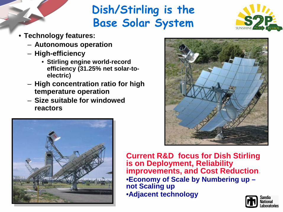
Dish/Stirling is the Base Solar System
• Technology features:– Autonomous operation – High-efficiency
• Stirling engine world-record efficiency (31.25% net solar-to-electric)
– High concentration ratio for high temperature operation
– Size suitable for windowed reactors
Current R&D focus for Dish Stirling is on Deployment, Reliability improvements, and Cost Reduction.•Economy of Scale by Numbering up –not Scaling up•Adjacent technology

Metal Oxide Wish List
• Negative ∆G for both thermal reduction and water oxidation reactions• At reasonable temperatures that couple with energy source• Can compensate by providing work in the form of separation or reduced pressure (will reduce system efficiency)
• High melting/Low volatility• Active over millions of cycles with no intermediate processing• Amenable to Fabrication/integration with engine design concept • Efficient volumetric/mass usage
• High surface area or bulk transport• Can compensate to some extent with recuperation
• Fast kinetics• No physical or chemical degradation with cycling
• Compatible with other materials of construction• Resistant to thermal shocking • Small volumetric changes with T or phase

CR5 Requires Cycle Times ~1 min.
30 g Cobalt ferriteTR ≥ 1350-1400 oC
CO2 Oxidation ≥ 1050-1100 oCCO2/He flow rate: 1 SLPM
0
0.1
0.2
0.3
0.4
0.5
0.6
0.7
10950 11150 11350 11550 11750 11950 12150
Time, s
%C
O
950
1000
1050
1100
1150
1200
1250
1300
1350
Mid
plan
e Te
mpe
ratu
re, C
CO concentrationMid-plane temperature
2 minute reactions 1 minute reactions
Water cooled panel
Window retaining clips
Quartz window
Gas inlet port
Ceramic insulation ring
Reactive material assembly
Water cooled panel
Window retaining clips
Quartz window
Gas inlet port
Ceramic insulation ring
Reactive material assembly
Splitting of CO2over Cobalt Ferrite MonolithSmall volume solar reactor

Reaction Kinetics Over Monoliths
Time (min.)0 10 20 30 40
Raw
Rat
e (c
m3 /m
in)
0.00
0.05
0.10
0.15
0.20
1400 °C1350 °C1300 °C1250 °C1100 °C1000 °C
1/T (1/K)
0.0006 0.0007 0.0008 0.0009In
itial
Oxi
datio
n R
ate
(µm
oles
/sec
)e-6
e-5
e-4
e-3
e-2
T (°C)9001100 100012001400
Ea = 21.7 Kcal/mol
Ea = 16.4 Kcal/mol
875 Torr CO2234 Torr H2O875 Torr CO2 (different sample)
Oxidation of 3% Fe2O3 in 8YSZ ("fully soluble")sample weight = 0.812 g
nominal surface area = 6 cm2
CO2 and H2O oxidation: Fe2O3/YSZ, CeZr, CeZr + Catalysts, CeO2
CO2 + 2Fe2+ = CO + (O-2 + 2Fe3+)

Comparison of Families of Materials
Time (minutes)
0 10 20 30 40 50 60R
ate
(cm
3 /min
)
0.00
0.02
0.04
0.06
0.08
0.10
0.12
0.14
0.16
CeO2 800 °C3% Fe2O3/YSZ 1400 °CCe0.5Zr0.5O2 1400 °C
Time (minutes)
0 5 10 15 20 25 30
Rat
e (c
m3 /m
in)
0.0
0.2
0.4
0.6
0.8
1.0
1.2
1.4
1.6
CeO2 800 °C3% Fe2O3/YSZ 1400 °CCe0.5Zr0.5O2 1400 °C
Utilization - CO (% of theor.)
Utilization – O2 (% of theor.)
Ea CO2 (kcal/mol)
Ea H2O (kcal/mol)
n [CO2]n
3% Fe2O3/YSZ 49 57 22 16 1-0 Ce0.5Zr0.5O2 8.7 33 30-40 22 0.6
CeO2 6.9 12 11 n.m. 0.75

Benchmarking Kinetics: Defined Flux
heig
ht
spacing
Simple Plates
1: h=s (2)2: h=4s (8)
3r3r
height
Vertical Pins
3: h=20r (14.3)A.R. = 10
4: h=40r (28.2)A.R. = 20
CO2 → CO + ½ O2Flux = 0.017 kW/cm2
Surface Area / Projected Surface Area0 10 20 30 40
Req
uire
d R
eact
ion
Rat
e (µ
mol
es/s
ec-c
m2 )
0.01
0.1
1
10
1 2 3 4
1%5%10%15%20%
Thermal to ChemicalEfficiency
CO2 + CeO2-x = CO + CeO2-x+δ (800 °C)
1000 °C*

CR5 Prototype Under Development
National Solar Thermal Test Facility

CR5 Prototype Test System
• Flow control challenging
– Need to avoid crossover between reactors
– ΔP between reactors extremely small (few Pa)
– O2 vacuum pump flow based on flow measurements, not differential pressure

CR5 Reactive Materials Are Challenging
• Robocast cobalt ferrite reactant spalled in first test (5/14/09)
– Poor solar penetration– Stress risers along thermal
gradients– Robocast design leaves no
room for failure (jams drive)• New “fin” design attempts to
addresses issues (10/15/09)– Good solar penetration– No stress risers (notches)– Failure less likely to bind rings– Thermal stresses/shock still
result in failures

CR5 Prototype Testing Ferrite/Thin Plate Geometry
• Temperatures controlled• No issues with quartz
window/cavity
October 15, 2009
0
200
400
600
800
1000
1200
1400
1600
0 500 1000 1500 2000 2500 3000 3500 4000
Time, sec
Tem
pera
ture
, C
0.00
0.20
0.40
0.60
0.80
1.00
1.20
1.40
1.60
1.80
Attn
uato
r Fra
ctio
n, D
NI,
kW/m
2 , RPM
Attenuator
DNI
TR Temp
Oxidation Temp
Window Temp
RPM
(a)

CR5 Prototype Testing Ferrite/Thin Plate Geometry
• CO2 splitting demonstrated• Continuous operation
• Separation of product CO and O2
0.00
5.00
10.00
15.00
20.00
25.00
0 500 1000 1500 2000 2500 3000 3500 4000Time, sec
Flow
, lit/
min
0.001
0.010
0.100
1.000
10.000
Con
cent
ratio
n, %
O2 Conc.
CO Pump Flow
CO Conc.
Ar Injector Flow
CO Injector Flow
Internal Purge FlowO2 Pump Flow
(b)

Thermochemical Cycles Are Heat Engines
• CR5 is analogous to conventional engines
– Converts high temperature thermal energy to work
– Operating temperatures & irreversibilities of internal processes are key to high efficiency
• Operation of CR5 prototype has power/efficiency tradeoffs
– Similar to conventional engines
– Thermochemical analogs to power and torque
0
0.1
0.2
0.3
0.4
0.5
0.6
0 0.2 0.4 0.6 0.8 1 1.2 1.4 1.6 1.8Speed, RPM
Effic
ienc
y
0
1
2
3
4
5
6
7
8
Qso
lar,
kW
Reaction Extent
0.050.030.030.05
0.02 0.02
0.01
0.01
TTR = 1800 KTWO = 1000 KP = 0.2 atm
Reaction Extent
0
100
200
300
400
500
600
700
0 0.2 0.4 0.6 0.8 1 1.2 1.4 1.6 1.8Speed, RPM
H2 P
rodu
ctio
n, li
t/hr
0.03
0.05
0.02
0.01
Reaction Extent
TTR = 1800 KTWO = 1000 KP = 0.2 atm

Baseline System Architecture Produces 10,000 kg/hr MeOH
Distributed CO2 splitting Centralized liquid fuels production
17,622 CR5/dishes
Economics: 30 year amortization with 15% interest

Capital associated with CO2 splitting is the major cost component
Current market price of methanol: $0.56/kg ($0.09/kW-hr)
Cost of methanol from baseline system: $1.75/kg ($0.25/kW-hr)4.8 kg/gallon
1.120
0.294
0.050
0.029
0.069 0.189
CR5 system
Separation system
WGS system
MS system
Raw material
Indirect capital cost and others
Total S2P costs per year: Total contribution of each S2P component:
Assumes: BOP electricity and steam are bought at market values30 year amortization with 15% interest

Summary
• Solar Fuels encompass more than biology.
• Efficiency is key for scalability (avoiding resource limits) and cost.– Sunlight is the high cost feedstock (capital to capture)– Adjacency to other technologies offers benefits
• Thermochemical approaches have great promise.– Potential for high efficiency– Field is rapidly advancing
• Advances are needed in materials– Chemical challenges: higher rates, better utilization– Physical challenges: high surface area, inert, low volatility,
resistant to thermal shock


![Innovative Solar Thermochemical Water Splitting · thermal energy. [2, 3] When mass-produced, concentrating solar power systems can be cost competitive with conventional energy sources.](https://static.fdocuments.in/doc/165x107/5ec09831bd179507a31aa01d/innovative-solar-thermochemical-water-splitting-thermal-energy-2-3-when-mass-produced.jpg)