Solar Connectors
4
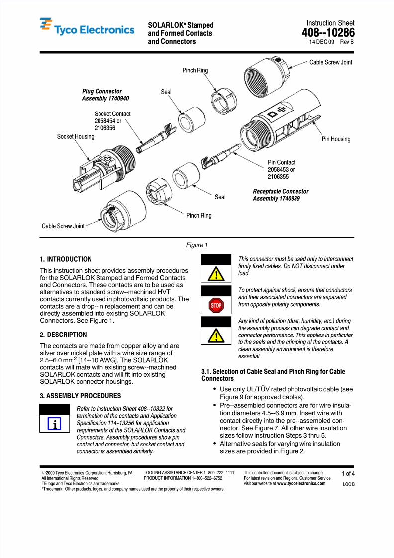
Instruction Sheet SOLARLOK* Stamped and Formed Contacts 408--10286 LOC B 1 of 4 E2009 Tyco Electronics Corporation, Harrisburg, P A All International Rights Reserved TE logo and Tyco Electronics are trademarks. *Trademark. Other products, logos, and company names used are the property of their respective owners. TOOLING ASSISTANCE CENTER 1--800--722--1111 PRODUCT INFORMATION 1--800--522--6752 This controlled document is subject to change. For latest revision and Regional Customer Service, visit our website at www.tycoelectronics.com 14 DEC 09 Rev B and Connectors Figure 1 Receptacle Connector Assembly 1740939 Plug Connector Assembly 1740940 Socket Housing Socket Contact 2058454 or 2106356 Seal Pinch Ring Cable Screw Joint Cable Screw Joint Pinch Ring Pin Contact 2058453 or 2106355 Pin Housing Seal 1. INTRODUCTION This instruction sheet provides assembly procedures for the SOLARLOK Stamped and Formed Contacts and Connectors. These contacts are to be used as alternatives to standard screw--machined HVT contacts currently used in photovoltaic products. The contacts are a drop--in replacement and can be directl y assembled into existing SOLARLOK Connectors. See Figure 1. 2. DESCRIPTION The contacts are made from copper alloy and are silver over nickel plate with a wire size range of 2.5--6.0 mm 2 [14--10 AWG]. The SOLARLOK contacts will mate with existing screw--machined SOLARLOK contacts and will fit into existing SOLARLOK connector housings. 3. ASSEMBLY PROCEDURES Refer to Instruction Sheet 408--10322 for termination of the contacts and Application Specification 114- -13256 for application requirements of the SOLARLOK Contacts and Connectors. Assembly procedures show pin contact and connector, but socket contact and connector is assembled similarly. This connector must be used only to interconnect firmly fixed cables. Do NOT disconnect under load. To protect against shock, ensure that conductors and their associated connectors are separated from opposite polarity components. Any kind of pollution (dust, humidity, etc.) during the assembly process can degrade contact and connector performance. This applies in particular to the seals and the crimping of the contacts. A clean assembly environment is therefore essential. 3.1. Selection of Cable Seal and Pinch Ring for Cable Connectors S Use only UL/TÜV rated photovoltaic cable (see Figure 9 for approved cables). S Pre--assembled connectors are for wire insula- tion diameters 4.5--6.9 mm. Insert wire with contact directly into the pre--assembled con- nector. See Figure 7. All other wire insulation sizes follow instruction Steps 3 thru 5. S Alternative seals for varying wire insulation sizes are provided in Figure 2. NOTE i CAUTION ! DANGER CAUTION !
-
Upload
deepak-dogra -
Category
Documents
-
view
217 -
download
0
Transcript of Solar Connectors
8/6/2019 Solar Connectors
http://slidepdf.com/reader/full/solar-connectors 1/4

8/6/2019 Solar Connectors
http://slidepdf.com/reader/full/solar-connectors 2/4

8/6/2019 Solar Connectors
http://slidepdf.com/reader/full/solar-connectors 3/4

8/6/2019 Solar Connectors
http://slidepdf.com/reader/full/solar-connectors 4/4