Soils for civil engineering purposes — Licensed copy ... · This method covers the determination...
70
BRITISH STANDARD BS 1377-9: 1990 Incorporating Amendments Nos. 1 and 2 Methods of test for Soils for civil engineering purposes — Part 9: In-situ tests ICS 93.020 Licensed copy:College Of North West London, 20/05/2014, Uncontrolled Copy, © BSI
Transcript of Soils for civil engineering purposes — Licensed copy ... · This method covers the determination...

Licensed copy:College Of North West London, 20/05/2014, Uncontrolled Copy, © BSI
BRITISH STANDARD
�������������� ���������������������������������������������������
BS 1377-9: 1990Incorporating Amendments Nos. 1 and 2
Methods of test for
Soils for civil engineering purposes —Part 9: In-situ tests
ICS 93.020

BS 1377-9:1990
Licensed copy:College Of North West London, 20/05/2014, Uncontrolled Copy, © BSI
This British Standard, having been prepared under the direction of the Road Engineering Standards Policy Committee, was published under the authority of the Board of the BSI and comes into effect on 31 August 1990
© BSI 2007
The following BSI references relate to the work on this standard:Committee reference RDB/38Draft for comment 88/10677 DC
ISBN 978 0 580 59295 9
Am
Am
82
17
Committees responsible for this British Standard
The preparation of this British Standard was entrusted by the Road Engineering Standards Policy committee (RDB/-) to Technical committee RDB/38, upon which the following bodies were represented:
Association of consulting EngineersBritish Civil Engineering Test Equipment Manufacturers’ AssociationCounty Surveyors’ SocietyDepartment of the Environment (Property Services Agency)Department of the Environment (Building Research Establishment)Department of TransportDepartment of Transport (Transport and Road Research Laboratory)Co-opted members
endments issued since publication
d. No. Date of issue Comments
64 January 1995
229 31 July 2007 Indicated by a sideline in the margin
BS 1377-9:1990
© BSI 2007Licensed copy:College Of North West London, 20/05/2014, Uncontrolled Copy, © BSI
Contents
PageCommittees responsible Inside front coverForeword iii1 Scope 12 In-situ density tests 12.0 Introduction 12.1 Sand replacement method suitable for fine- and
medium-grained soils (small pouring cylinder method) 12.2 Sand replacement method suitable for
fine-, medium- and coarse-grained soils (large pouring cylinder method) 3
2.3 Water replacement method suitable for coarse-grained soils 62.4 Core cutter method for cohesive soils free from
coarse-grained material 92.5 Nuclear methods suitable for fine-, medium- and
coarse-grained soils 103 In-situ penetration tests 183.0 Introduction 183.1 Determination of the penetration resistance using the
fixed 60° cone and friction sleeve (static cone penetration test CPT) 18
3.2 Determination of the dynamic probing resistance using the 90° cone (dynamic probing DP) 22
3.3 Determination of the penetration resistance using the split-barrel sampler (the standard penetration test SPT) 23
4 In-situ vertical deformation and strength tests 234.0 Introduction 234.1 Determination of the vertical deformation and strength
characteristics of soil by the plate loading test 234.2 Determination of the settlement characteristics of soil for
lightly loaded foundations by the shallow pad maintained load test 27
4.3 Determination of the in-situ California Bearing Ratio (CBR) 294.4 Determination of the in-situ vane shear strength of weak
intact cohesive soils 325 In-situ corrosivity tests 345.0 Introduction 345.1 Determination in-situ of the apparent resistivity of soil 345.2 Determination in-situ of the redox potential of soil 35Appendix A Typical test data and calculation forms 55Figure 1 — Small pouring cylinder for the determination of the density of fine- and medium-grained soils 39Figure 2 — Scraper for levelling surface of soil 40Figure 3 — Calibrating container for use with the small pouring cylinder 41Figure 4 — Large pouring cylinder for the determination of the density of fine-, medium- and coarse-grained soils 42Figure 5 — Calibrating container for use with large pouring cylinder 43Figure 6 — Core-cutter apparatus for soil density determination 44Figure 7 — Modes of operation of nuclear surface density and moisture gauges 45
i
BS 1377-9:1990
iiLicensed copy:College Of North West London, 20/05/2014, Uncontrolled Copy, © BSI
PageFigure 8 — Examples of penetrometer tips with and without a friction sleeve 46Figure 9 — Permitted tolerances, including allowances for wear, surface finish and typical manufacturing dimensions for the standard cone for the cone penetration test 47Figure 10 — Permitted tolerances, including allowances for wear, surface finish and typical manufacturing dimensions for the standard friction sleeve for the cone penetration test 48Figure 11 — Alternative forms of 90° cone for dynamic probing 48Figure 12 — Split-barrel sampler assembly 49Figure 13 — Typical arrangement for in-situ CBR test apparatus 50Figure 14 — Typical CBR test results curves 51Figure 15 — Force-penetration curves for a CBR value of 100 % and other CBR values 52Figure 16 — Typical arrangements for in-situ vane test apparatus 53Figure 17 — Typical borehole vane and rod mounting 54Figure 18 — Typical vane protecting shoe 54Publications referred to Inside back cover
© BSI 2007

BS 1377-9:1990
© BSI 2007Licensed copy:College Of North West London, 20/05/2014, Uncontrolled Copy, © BSI
Foreword
This Part of BS 1377 has been prepared under the direction of the Road Engineering Standards Policy Committee. It is a revision of the in-situ test methods described in BS 1377:1975 which are superseded by amendment.NOTE Amendment 2 to this standard removes text superseded by BS EN ISO 22476-2 and BS EN ISO 22476-3, and makes reference to the relevant standard for each affected subclause.
BS 1377:1975 which has now been withdrawn is replaced by the following Parts of BS 1377:1990:
— Part 1: General requirements and sample preparation;— Part 2: Classification tests;— Part 3: Chemical and electro-chemical tests;— Part 4: Compaction-related tests;— Part 5: Compressibility, permeability and durability tests;— Part 6: Consolidation and permeability tests in hydraulic cells and with pore pressure measurement;— Part 7: Shear strength tests (total stress);— Part 8: Shear strength tests (effective stress);— Part 9: In-situ tests.
Regarding the in-situ test methods in BS 1377:1975, all have been retained except Test 15(C), determination of the dry density of fine-, medium- and coarse-grained soils by the hand scoop method. Regarding Test 15(C), a new test for coarse-grained soils has been substituted, based on a water replacement method that provides a more reliable result. With Test 19, determination of the penetration resistance using the split-barrel sampler, the method has been revised to conform more closely to international practice.In addition to the change in the method for determining the density of coarse-grained soils, referred to above, the opportunity has been taken to add other test methods as follows:
Determination of the in-situ bulk density and moisture content of fine-, medium- and coarse-grained soils by attenuation of gamma rays and moderation of neutrons respectively.Determination of the penetration resistance using the fixed 60° cone and friction sleeve (the static cone penetration test CPT).Determination of the dynamic probing resistance using the 90° cone (dynamic probing DP).Determination of the vertical deformation and strength characteristics of soil by the plate loading test.Determination of the settlement characteristics of soil for lightly loaded foundations by the shallow pad maintained load test.Determination of the in-situ California Bearing Ratio (CBR).Determination of the in-situ apparent resistivity of soil.Determination of the in-situ redox potential of soil.
In each of the test methods the measurement of only one value of the overall result is required. It is recognized that it is necessary in many practical applications to make a number of tests in order to obtain a mean value and an indication of its reliability. Guidance on the number of measurements required and the treatment of the results obtained is regarded as being beyond the scope of this Part of the standard.Consideration was given to the inclusion of a test method for pressure meters but it was decided that it would be restrictive at this stage to formulate a standard.
iii

BS 1377-9:1990
ivLicensed copy:College Of North West London, 20/05/2014, Uncontrolled Copy, © BSI
General information relevant to the tests and common specification requirements applicable to a number of tests are given in Part 1 of this standard. Reference should always be made to this Part for any particular in-situ test method. For general information on site investigation procedures, especially with regard to safety precautions, reference should be made to BS 5930:1981.Typical forms are included for a number of the test methods to illustrate how the results may conveniently be recorded and calculated. The layout of such forms is a matter of individual preference. This information is given in Appendix A.It has been assumed in the drafting of this British Standard that the execution of its provisions is entrusted to appropriately experienced people, for whose guidance it has been prepared.A British Standard does not purport to include all the necessary provisions of a contract. Users of British Standards are responsible for their correct application.
Compliance with a British Standard cannot confer immunity from legal obligations.
© BSI 2007
Summary of pagesThis document comprises a front cover, an inside front cover, pages i to iv, pages 1 to 62, an inside back cover and a back cover.This standard has been updated (see copyright date) and may have had amendments incorporated. This will be indicated in the amendment table on the inside front cover.

BS 1377-9:1990
Licensed copy:College Of North West London, 20/05/2014, Uncontrolled Copy, © BSI
1 ScopeThis Part of BS 1377 describes in-situ methods of test on soils for civil engineering purposes, i.e. tests made directly on the soil in place as distinct from laboratory tests, described in Parts 2 to 8 of this standard, for which samples first need to be taken. The methods described in this Part of this standard have been arranged in groups either according to the purpose of the test or the mode of execution. These groups are as follows.
a) Five methods for the determination of the in-situ density.b) Three methods for the determination of penetration resistances.c) Four methods for the determination of the vertical deformation and strength characteristics.d) Two methods for the determination of the in-situ corrosivity characteristics.
NOTE The titles of the publications referred to in this standard are listed on the inside back cover.
2 In-situ density tests2.0 IntroductionThis clause specifies five methods for determining the in-situ density of soil, four of which use the direct measurements of mass and volume, the choice of which depends upon the type of material, and one method uses gamma rays. The last named also includes the measurement of moisture content with nuclear gauges that combine both facilities.2.1 Sand replacement method suitable for fine- and medium-grained soils (small pouring cylinder method)2.1.1 General. This method covers the determination in-situ of the density of natural or compacted fine- and medium-grained soils for which a 115 mm diameter sand-pouring cylinder is used in conjunction with replacement sand (see note 1). The method is applicable to layers not exceeding 150 mm in thickness (see note 2).NOTE 1 With granular materials having little or no cohesion particularly when they are wet, there is a danger of errors in the measurement of density by this method. These errors are caused by the slumping of the sides of the excavated density hole and always result in an over-estimation of the density.NOTE 2 For layers between 150 mm and 250 mm in thickness the test described in 2.2 should be used.The requirements of Part 1 of this standard, where appropriate, shall apply to the test methods described in this clause.2.1.2 Apparatus2.1.2.1 A pouring cylinder, similar in detail to that shown in Figure 1.
2.1.2.2 Suitable tools for excavating holes in soil, e.g. a bent spoon dibber and a scraper tool, similar to that shown in Figure 2, to make a level surface.2.1.2.3 Cylindrical, metal, calibrating container, with an internal diameter of 100 ± 2 mm and an internal depth of 150 ± 3 mm of the type illustrated in Figure 3, fitted with a lip 50 mm wide and about 5 mm thick surrounding the open end.2.1.2.4 Balance, readable to 1 g.2.1.2.5 Glass plate, a convenient size being one at least 10 mm thick and about 500 mm square.2.1.2.6 Metal tray or container to take excavated soil, a convenient size being one about 300 mm in diameter and about 40 mm deep.2.1.2.7 A cylindrical, steel core cutter (for fine-grained cohesionless soils), 130 mm long and 100 ± 2 mm internal diameter, with a wall thickness of 3 mm bevelled at one end. One suitable type is illustrated in Figure 6. This cutter shall be kept lightly greased.2.1.2.8 Apparatus for moisture content determination as specified in BS 1377-2:1990.2.1.2.9 A metal tray about 300 mm square and about 40 mm deep with a 100 mm diameter hole in the centre.2.1.3 Material. The replacement sand shall be a clean closely graded silica sand which provides a bulk density that is reasonably consistent. The grading of the sand shall be such that 100 % passes a 600 µm test sieve and 100 % is retained on the 63 µm test sieve. In addition it shall be free from flakey particles, silt, clay and organic matter. Before using, it shall have been oven dried and stored in a loosely covered container to allow its moisture content to reach equilibrium with atmospheric humidity.NOTE Generally a storage period, after oven drying, of about 7 days is sufficient for the moisture content of the sand to reach equilibrium with the atmospheric humidity. The sand should be mixed thoroughly before use. If sand is salvaged from holes in compacted soils after carrying out this test, it should be sieved, dried and stored again before it is used in further sand replacement tests.
2.1.4 Calibrations2.1.4.1 Determination of the mass of sand in the cone of the pouring cylinder2.1.4.1.1 Fill the pouring cylinder so that the level of the sand in the cylinder is within about 15 mm of the top. Find its total initial mass, m1, to the nearest 1 g and always use the same initial mass for every calibration. Maintain this constant throughout the tests for which the calibration is used. Allow a volume of sand equivalent to that of the excavated hole in the soil (or equal to that of the calibrating container) to run out.
© BSI 2007 1

BS 1377-9:1990
Licensed copy:College Of North West London, 20/05/2014, Uncontrolled Copy, © BSI
Close the shutter on the pouring cylinder and place the cylinder on a plane surface, e.g. the glass plate.2.1.4.1.2 Open the shutter on the pouring cylinder and allow sand to run out. Do not tap or otherwise vibrate during this period. When no further movement of sand takes place in the cylinder, close the shutter and remove the cylinder carefully.2.1.4.1.3 Collect the sand on the glass plate that had filled the cone of the pouring cylinder and determine its mass, m2, to the nearest 1 g.2.1.4.1.4 Repeat these measurements at least three times and calculate the mean value of m2.2.1.4.2 Determination of the bulk density of the sand (ρa)2.1.4.2.1 Determine the internal volume, V (in mL), of the calibrating container.NOTE The following method for determining the volume of the calibrating container has been found both convenient and accuratePlace the empty container on the flat pan of the balance, ensuring that the upper rim of the container is horizontal, if necessary by embedding the base in modelling clay or similar material. Note the mass of the container, together with any modelling clay, to the nearest 1 g (m5). Then fill the calibrating container almost completely with water, taking care not to spill water upon the pan of the balance or the outside of the container. Lay a straightedge across the top of the container and add water slowly and carefully by means of a dropping rod until the water just touches the straightedge. Remove the straightedge and note the mass of the container plus water to the nearest 1 g (m6). Repeat the measurement a number of times to obtain an accurate mean value of m6. For the repeat tests it is only necessary to remove a small amount of water by means of the dropping rod and to refill the container to the level of the straightedge. The volume of the calibrating container, V (in mL), is given by the equation:
V = m6 – m52.1.4.2.2 Place the pouring cylinder concentrically on the top of the calibrating container after it has been filled to the constant mass, m1, as specified in 2.1.4.1.1. Keep the shutter on the pouring cylinder closed during this operation. Open the shutter and allow the sand to run out. Do not tap the pouring cylinder or otherwise vibrate it during this period. When no further movement of sand takes place in the cylinder, close the shutter. Remove the pouring cylinder with the sand remaining in it and determine their combined mass, m3, to the nearest 1 g.NOTE The calibrating container should stand on a large tray during this part of the test procedure to collect the sand overflowing from the cone when the cylinder is removed.
2.1.4.2.3 Repeat these measurements at least three times and calculate the mean value of m3.NOTE Since variations in atmospheric humidity affect the moisture content of the sand, and hence its bulk density, the calibration should be made, or at least checked, during each day’s work. To overcome the effects of slight variations in grading and particle shape between batches of sand, each batch should be sampled and calibrated.
2.1.5 Procedure2.1.5.1 Expose a flat area, approximately 450 mm square, of the soil to be tested and trim it down to a level surface, preferably with the aid of the scraper tool. Brush away any loose extraneous material.2.1.5.2 Lay the metal tray on the prepared surface with the hole over the portion of the soil to be tested. Using this hole as a pattern, excavate a round hole, approximately 100 mm in diameter and the depth of the layer to be tested up to a maximum of 150 mm deep. Do not leave loose material in the hole and do not distort the immediate surround to the hole. Carefully collect all the excavated soil from the hole and determine its mass, mw, to the nearest 1 g. Remove the metal tray before placing the pouring cylinder in position over the excavated hole.NOTE Take care in excavating the hole to see that the hole is not enlarged by levering the excavating tool against the side of the hole, as this will result in lower densities being recorded.2.1.5.3 Alternative method for fine-grained cohesionless soils (see note).Without using the metal tray, press the steel core cutter (Figure 6) evenly and carefully into the soil untill its top edge is flush with the levelled surface. Excavate the soil to a depth of about 120 mm within the core cutter by means of suitable tools. Carefully collect the excavated soil and determine its mass, mw, to the nearest 1 g. Keep the core cutter in position during the remainder of the testing procedure.NOTE The procedure specified in 2.1.5.3 should only be employed when the fine-grained cohesionless soil is in such a condition that, when using the procedure specified in 2.1.5.2, a cylindrical hole cannot be formed because of the instability of the sides of the hole. The use of the core cutter will produce some disturbance in the soil and, where this procedure is necessary, due allowance should be made for a lower standard of accuracy than would normally be expected with the sand replacement method.2.1.5.4 Place a representative sample of the excavated soil in an airtight container and determine its moisture content, w, as specified in BS 1377-2:1990. Alternatively, the whole of the excavated soil shall be dried and its mass, md, determined.
2 © BSI 2007

BS 1377-9:1990
Licensed copy:College Of North West London, 20/05/2014, Uncontrolled Copy, © BSI
2.1.5.5 Place the pouring cylinder, filled to the constant mass, m1, as specified in 2.1.4.1.1 so that the base of the cylinder covers the hole concentrically. Ensure the shutter on the pouring cylinder is closed during this operation. Open the shutter and allow sand to run out; during this period do not vibrate the cylinder or the surrounding area. When no further movement of the sand takes place close the shutter. Remove the cylinder and determine its mass, m4, to the nearest 1 g.2.1.6 Calculations1) and expression of results. Calculate the mass of sand, ma (in g), required to fill the calibrating container from the equation:
ma = m1 – m3 – m2where
Calculate the bulk density of the sand, ρa (in Mg/m3), from the equation:
whereV is the volume of the calibrating container
(in mL).Calculate the mass of sand required to fill the excavated hole, mb (in g), from equation:
mb = m1 – m4 – m2where
Calculate the bulk density of the soil, ρ (in Mg/m3), from the equation:
where
Calculate the dry density, ρd (in Mg/m3), from the equation:
wherew is the moisture content of the soil (in %).
or
where
2.1.7 Test report. The test report shall affirm that the test was carried out in accordance with this Part of this standard and shall contain the following information:
a) the method of test used;b) the in-situ bulk and dry densities of the soil (in Mg/m3) to the nearest 0.01 Mg/m3;c) the moisture content, as a percentage to two significant figures;d) the information required by clause 9 of BS 1377-1:1990.
2.2 Sand replacement method suitable for fine-, medium- and coarse-grained soils (large pouring cylinder method)2.2.1 General. This method covers the determination in situ of the density of natural or compacted soil containing coarse- grained particles which make the test described in 2.1 difficult to perform. It is an alternative to that test for fine- and medium-grained soils and should be used instead of that test for layers exceeding 150 mm, but not exceeding 250 mm in thickness (see note).With granular materials having little or no cohesion, particularly when they are wet, there is a danger of errors in measurement of density by this method. These errors are caused by the slumping of the sides of the excavated density hole and always result in an over-estimation of density. In such cases the test described in 2.3 should be selected.
1) See form 9(a) of Appendix A.
m1 is the mass of cylinder and sand before pouring into calibrating container (in g);
m2 is the mean mass of sand in cone (in g);m3 is the mean mass of cylinder and sand after
pouring into calibrating container (in g).
m1 is the mass of cylinder and sand before pouring into hole (in g);
m2 is the mean mass of sand in cone (in g);
m4 is the mass of cylinder and sand after pouring into hole (in g).
mw is the mass of soil excavated (in g);
ρamaV
--------=
ρmwmb-------⎝ ⎠⎛ ⎞ρa=
mb is the mass of sand required to fill the hole (in g);
ρa is the bulk density of sand (in Mg/m3).
md is the mass of dry soil from the hole (in g);mb is the mass of sand required to fill the hole
(in g).
ρd100 ρ
100 w+---------------------=
ρmdmb--------⎝ ⎠⎛ ⎞ ra=
© BSI 2007 3

BS 1377-9:1990
Licensed copy:College Of North West London, 20/05/2014, Uncontrolled Copy, © BSI
The test described in 2.3 should also be used when very coarse-grained material is present.NOTE If for any reason it is necessary to excavate holes other than 250 mm the calibrating container should be replaced by one with the same depth as the hole excavated, or its effective depth reduced to that of the hole excavated.The requirements of Part 1 of this standard, where appropriate, shall apply to the test methods described in this clause.2.2.2 Apparatus2.2.2.1 A pouring cylinder similar in detail to that shown in Figure 4.2.2.2.2 Suitable tools for excavating holes in compacted soil, e.g. a bent spoon dibber, large screwdriver and/or pointed steel rod about 250 mm long and 7 mm to 10 mm in diameter with a handle.2.2.2.3 Cylindrical metal calibrating container with an internal diameter of 200 ± 5 mm and an internal depth of 250 mm (see note to 2.2.1), of the type shown in Figure 5, fitted with a lip about 75 mm wide and about 5 mm thick surrounding the open end.2.2.2.4 Balance, readable to 10 g.NOTE The total mass of the pouring cylinder and sand is large so that the method of filling and weighing is to weigh the sand in two or three containers and tip it into the pouring cylinder before using. Take care to see that the same constant initial mass as is used in calibrating the apparatus is used for each density measurement. Sufficient sand should be used so that about 4 kg to 5 kg of sand is left in the pouring cylinder after the test is completed.2.2.2.5 A glass plate or other plane surface, a convenient size being one at least 10 mm thick and about 500 mm square.2.2.2.6 Metal trays or containers to take the excavated soil and to take the supply of sand to fill the pouring cylinder.2.2.2.7 Apparatus for moisture content determination as specified in BS 1377-2:1990.2.2.2.8 A metal tray about 500 mm square and about 50 mm deep with a 200 mm diameter hole in the centre.2.2.3 Material. The replacement sand shall be a clean closely graded silica sand which provides a bulk density that is reasonably consistent. The grading of the sand shall be such that 100 % passes a 600 µm test sieve and 100 % is retained on a 63 µm test sieve. In addition it shall be free from flakey particles, silt, clay and organic matter. Before use it shall have been oven dried and stored in a loosely covered container to allow its moisture content to reach equilibrium with atmospheric humidity.
NOTE After oven drying, a storage period generally of about 7 days is sufficient for the moisture content of the sand to reach equilibrium with the atmospheric humidity. The sand should not be stored in airtight containers and should be mixed thoroughly before use. If sand is salvaged from holes in compacted soils after carrying out this test, it is advisable to sieve, dry and store this sand again before it is used in further sand replacement tests.
2.2.4 Calibrations2.2.4.1 Determination of the mass of sand in the cone of the pouring cylinder2.2.4.1.1 Fill the pouring cylinder with a given initial mass of sand, m1, weighed to the nearest 10 g and always use the same initial mass for every calibration. Maintain this mass constant throughout the tests for which the calibration is used (see note to 2.2.2.4). Allow a volume of sand equivalent to that of the excavated hole in the soil, or equal to that of the calibrating container, to run out. Close the shutter on the pouring cylinder and place the cylinder on a plane surface, e.g. the glass plate.2.2.4.1.2 Open the shutter on the pouring cylinder and allow sand to run out. Do not tap or otherwise vibrate the pouring cylinder during this period. When no further movement of sand takes place in the cylinder, close the shutter and carefully remove the cylinder.2.2.4.1.3 Collect the sand on the plane surface that had filled the cone of the pouring cylinder and determine its mass, m2, to the nearest 10 g.2.2.4.1.4 Repeat these measurements at least three times and calculate the mean value of m2.2.2.4.2 Determination of the bulk density of the sand (ρa)2.2.4.2.1 Determine the internal volume, V (in mL), of the calibrating container by the mass of water required to fill it. (See note to 2.2.2.4.)NOTE The following method for determining the volume of the calibrating container has been found both convenient and accurate.Place the empty calibrating container on a flat surface, ensuring that its upper rim is horizontal, if necessary by embedding the base in modelling clay or similar material. Fill a suitable container (or containers) with water and weigh (m5) to the nearest 10 g and then fill the calibrating container almost completely with water from the weighed container. Lay a straightedge across the top of the calibrating container and add more water slowly and carefully from the weighed container by means of a dropping rod until the water just touches the straightedge. Take care that no water is spilled during these operations. Then reweigh the water container (or containers) (m6).Repeat the measurement a number of times to obtain an accurate mean value for m6. For the repeat tests it is only necessary to remove a small amount of water from the filled calibrating container by means of the dropping rod, return it to the weighed container, and to refill the calibrating container to the level of the straightedge. The volume of the calibrating container, V in mL, is given by the following equation:
V = m5 – m6
4 © BSI 2007

BS 1377-9:1990
Licensed copy:College Of North West London, 20/05/2014, Uncontrolled Copy, © BSI
2.2.4.2.2 Place the pouring cylinder concentrically on the top of the calibrating container and fill with the constant mass of sand (m1) as specified in 2.2.4.1.1. Keep the shutter on the pouring cylinder closed during this operation. Open the shutter and allow the sand to run out. Do not tap or otherwise vibrate the pouring cylinder during this period. When no further movement of the sand takes place in the cylinder, close the shutter. Remove the pouring cylinder and determine the mass of sand remaining in it (m3) to the nearest 10 g.NOTE The calibrating container should stand on a large tray during this part of the test procedure, to collect the sand overflowing from the cone when the cylinder is removed.2.2.4.2.3 Repeat these measurements at least three times, and calculate the mean value of m3.NOTE Since variations in atmospheric humidity affect the moisture content of the sand, and hence its bulk density, the calibration should be made, or at least checked, during each day’s work. To overcome the effects of slight variations in grading and particle shape between batches of sand, each batch should be sampled and calibrated.
2.2.5 Procedure2.2.5.1 Expose a flat area, approximately 600 mm square, of the soil to be tested and trim it down to a level surface. Brush away any loose extraneous material.2.2.5.2 Lay the metal tray on the prepared surface with the hole over the portion of the soil to be tested. Using this hole as a pattern excavate a round hole, approximately 200 mm in diameter and the depth of the layer to be tested up to a maximum of 250 mm (see note to 2.2.1). Do not leave loose material in the hole and do not distort the immediate surround to the hole. Carefully collect the excavated soil from the hole and determine its mass (mw) to the nearest 10 g.Remove the metal tray before placing the pouring cylinder in position over the excavated hole.NOTE Care should be taken in excavating the hole to see that the hole is not enlarged by levering the excavating tool against the side of the hole, as this will result in lower densities being recorded.2.2.5.3 Place a representative sample of the excavated soil in an airtight container and determine its moisture content, w, as specified in BS 1377-2:1990.
2.2.5.4 Place the pouring cylinder filled with the constant mass of sand (m1) as specified in 2.2.4.1.1 so that the base of the cylinder covers the hole concentrically. Keep the shutter on the pouring cylinder closed during this operation. Open the shutter and allow sand to run out; during this period do not vibrate the pouring cylinder or the surrounding area. When no further movement of the sand takes place, close the shutter. Remove the pouring cylinder and determine the mass of sand remaining in it (m4) to the nearest 10 g.2.2.6 Calculations2) and expression of results. Calculate the mass of sand required to fill the calibrating container, ma (in g), from the equation:
ma = m1 – m3 – m2where
Calculate the bulk density of the sand, ρa (in Mg/m3), from the equation:
whereV is the volume of the calibrating container
(in mL).Calculate the mass of sand required to fill the excavated hole, mb (in g), from the equation:
mb = m1 – m4 – m2where
Calculate the bulk density of the soil, ρ (in Mg/m3), from the equation:
where
2) See form 9(a) of Appendix A.
m1 is the mass of sand before pouring in the calibrating container (in g);
m2 is the mean mass of sand in cone (in g);
m3 is the mean mass of sand after pouring into the calibrating container (in g).
m1 is the mass of sand before pouring into the hole (in g);
m2 is the mean mass of sand in cone (in g);
m4 is the mass of sand after pouring into the hole (in g).
mw is the mass of soil excavated (in g);mb is the mass of sand required to fill the hole
(in g);
ρamaV
--------=
ρmwmb---------⎝ ⎠⎛ ⎞ ρa=
© BSI 2007 5

BS 1377-9:1990
Licensed copy:College Of North West London, 20/05/2014, Uncontrolled Copy, © BSI
Calculate the dry density, ρd (in Mg/m3), from the equation:
wherew is the moisture content of the soil (in %).
2.2.7 Test report. The test report shall affirm that the test was carried out in accordance with this Part of this standard and shall contain the following information.
a) The method of test used.b) The in-situ bulk and dry densities of the soil (in Mg/m3) to the nearest 0.01 Mg/m3.c) The moisture content, as a percentage, to two significant figures.d) The information required by clause 9 of BS 1377-1:1990.
2.3 Water replacement method suitable for coarse-grained soils2.3.1 General. This method covers the determination in-situ of the density of natural or compacted coarse-grained soil using a circular density ring on the ground surface and a flexible plastics sheet to retain water to determine the volume of an excavated hole. The method is used in coarse and very coarse soils when the other methods for determining the field density are unsuitable because the volume excavated would be unrepresentative.Alternative density determinations may be made as follows:
a) for the total material within the hole excavated (see 2.3.5.1):
1) to an unspecified depth;2) to a specified depth;3) in successive tests as a hole is progressively deepened in order to determine the variation of density with increasing depth, e.g. when placing and compacting material in specified stages.
b) for the proportion of the soil finer than a specified size, normally not less than coarse gravel (see 2.3.5.2).
The requirements of Part 1 of this standard, where appropriate, shall apply to the test methods described in this clause.
2.3.2 Apparatus. The following list of apparatus applies to both procedures a) and b). (See 2.3.5.1 and 2.3.5.2 respectively.) The number and size of the items will vary with the type of material present and the size of the hole to be excavated.2.3.2.1 Density ring of rigid construction providing an unobstructed inner surface that is of a right cylinder approximately 100 mm high for rings up to 500 mm nominal internal diameter and 200 mm high for larger diameters. The ring shall be provided externally with a means for securing its position on the ground surface, e.g. metal spikes. The ring diameter shall be several times larger than the largest-sized particle (see note).NOTE As a general guide the ring diameter should be at least five times the size of the largest particle in well-graded soil but more if uniformly coarse. Diameters usually range from 500 mm to 2.5 m. Ring sizes larger than 500 mm nominal diameter are usually constructed in several segments which can be assembled at the site. If necessary to ensure rigidity of the ring it should be fitted with an external flange.2.3.2.2 Rigid straightedge sufficiently long to level the area of the density ring to be used.2.3.2.3 Spirit level of suitable length to use with the straightedge in order to level the density ring.2.3.2.4 Pointer gauge assembly consisting of an adjustable vertical pointer that can be locked in a fixed position, which is mounted on a datum bar that is removable during the test and can be replaced precisely so that the pointer is in the same position. The tip of the pointer is used to judge the final water level.NOTE For the smaller density rings the pointer may be mounted on a datum bar supported on legs which remain in position throughout the test and are driven into the ground outside the ring. For the larger rings, which are generally more stable, it is usual for the datum bar to be slightly longer than the diameter of the ring and for it to rest on the rim of the ring, marking the position so that it can be returned precisely to the same position. In this case the pointer is in the centre of the datum bar with a clamp for adjusting the height.2.3.2.5 Calibrated water containers (see also 2.3.4.1), of suitable capacity for the water supply, each with a volume measuring gauge and a suitable delivery hose which shall be fitted with a valve close to the exit in order to facilitate close control of the water flow into the flexible plastics sheet. Graduations on the measuring gauges shall be clearly marked and shall permit measurements to be made within 0.3 % of the volume of the hole excavated.2.3.2.6 Balance or balances readable to 100 g.2.3.2.7 Sample containers, suitable for holding the excavated soil and for the measurement of its mass.NOTE Soils and absorbent rocks holding significant amounts of water require containers with close-fitting lids. For material consisting of predominantly hard, non-absorbent rock of negligible moisture content open containers are satisfactory.
ρa is the bulk density of the sand (in Mg/m3).
ρd100 ρ
100 w+---------------------=
6 © BSI 2007

BS 1377-9:1990
Licensed copy:College Of North West London, 20/05/2014, Uncontrolled Copy, © BSI
2.3.2.8 Digging tools for excavating and removing material from the hole, e.g. pick, shovel, vibrating hammer and chisel point, crowbar, broom, handbrush and scoop.NOTE When very coarse material may be encountered in the excavation it is advisable to provide mechanical excavation and lifting equipment.2.3.2.9 Self-priming pump with suction and delivery hose for removing water from within the flexible plastics sheet.2.3.2.10 Mixing equipment for the quick-setting plaster, such as a bucket and a perforated disc on the end of a pole.2.3.2.11 Apparatus for moisture content determination as specified in BS 1377-2:1990.2.3.2.12 Test sieves, if required.2.3.2.13 Apparatus for dry density determination as specified in clause 7 of BS 1377-2:1990, if required.2.3.3 Materials2.3.3.1 Flexible plastics sheet that will mould to the shape of the hole yet is sufficiently thick not to be punctured by angular material.NOTE Black polyethylene sheet 0.1 mm thick in 2 m to 4 m squares is suitable for density rings up to 1.5 m nominal diameter. Alternatively a prefabricated cylindrical liner 0.1 mm thick may be used with density rings 500 mm diameter and smaller. Polyethylene sheet 0.2 mm thick in 6 m to 8 m squares is suitable for density rings above 1.5 m and up to 2.5 m nominal diameter.The use of transparent flexible sheeting aids identification of leaks in relatively dry materials and can assist when moulding the sheeting to fit the shape of the hole.2.3.3.2 Plaster of Paris.2.3.3.3 Clean water.2.3.4 Calibration2.3.4.1 Calibrated water containers. Calibrate each container, fitted with its delivery hose and control valve, by locating it on a level base and filling with clean water to the top graduation on the volume measuring gauge. Then drain via the hose successive volumes into a separate container so that the water level drops to each graduation in turn. Calculate each successive volume of water in litres as it is drained into the separate container by weighing or volume measurement. Plot the actual cumulative volume of water in each calibrated container against the graduation scale.2.3.5 Procedure. Since there are stages in both test procedures which cannot be repeated, all observations and recordings shall be independently checked as the test proceeds.2.3.5.1 Procedure for determining the density of the total material within the hole excavated2.3.5.1.1 Select a suitable size of density ring such that its internal diameter exceeds by five times the size of the largest particle expected to be present.
2.3.5.1.2 Prepare a horizontal flat area, sufficiently large to accommodate the selected density ring, and remove all loose material and sharp projections from the surface.2.3.5.1.3 Mix the plaster of Paris with water into a thick quick-setting paste sufficient to bed the density ring. Mark the position to be occupied by the density ring. Place a thin layer of the plaster paste over the area to be covered by the annulus of the density ring.2.3.5.1.4 Bed the density ring on the plaster paste ensuring that there are no voids remaining between the ring and the prepared surface of the ground. Secure the ring in place using the spikes. Trim away any surplus plaster paste from inside the ring.2.3.5.1.5 Set up the pointer gauge assembly so that the datum bar can be removed from the test area between readings and the tip at the lower end of the adjustable vertical pointer can be returned to a fixed position below the top of the ring.Remove the datum bar and locked pointer to a safe position away from the test area, leaving the support in place if this is part of the assembly.2.3.5.1.6 Select a suitable size of the plastics sheet or liner and check that it is undamaged and without punctures. Place the plastics sheet over the ring and prepared surface ensuring that it closely conforms to the surface of the soil and the inside of the ring. Replace the datum bar and locked pointer.2.3.5.1.7 Fill the space contained by the plastics sheet up to the precise level of the tip of the locked pointer with water from a calibrated container. While filling ensure that the plastics sheet makes full contact with the prepared surface and the inside of the density ring.After filling observe the water level at the pointer tip for several minutes in order to determine whether water is leaking through the plastics sheet. If leaking occurs or is suspected replace the plastics sheet with a sound piece and repeat the volume measurement. The measured volume of water used shall be within 0.1 % of the total volume being measured. This volume is the initial reading (Ri) which shall be recorded in litres.2.3.5.1.8 Remove the datum bar and locked pointer to a safe position. Remove the water and the plastics sheet, checking the prepared surface for indication of leakage. If leaking is found to have occurred repeat stages 2.3.5.1.6 and 2.3.5.1.7.
© BSI 2007 7

BS 1377-9:1990
Licensed copy:College Of North West London, 20/05/2014, Uncontrolled Copy, © BSI
2.3.5.1.9 Excavate with the digging tools a hole within the density ring as nearly cylindrical as practicable taking care not to displace the ring or the plaster filling. With non-cohesive soil, particularly when wet, the sides of the excavation will need to be inclined to prevent slumping. Carefully collect all the excavated material in suitable containers, which shall be fitted with lids for soils and absorbent rock fragments, and number them consecutively. As the hole is deepened avoid undercutting the ring and use mechanical lifting devices if necessary for removing very large material clear of the hole and over the ring. Leave in place any large rocks that protrude when forming the hole boundary.Keep the floor and wall of the hole flat and free from sharp protrusions which may puncture the plastics sheet. Cease excavating when the depth of the hole is more or less equal to its diameter, except when specified otherwise such as when testing particular layers.Ensure the hole is finally cleared of all loose material with the wall and base left undisturbed.2.3.5.1.10 Weigh each container of excavated material, as well as any separate very coarse-sized material, to the nearest 100 g and record the result with the container number. After deducting the masses of the containers, sum the individual masses of the material in order to obtain the total excavated mass (mw).2.3.5.1.11 When moisture or absorbent material is present in all or part of the excavated soil and rock which may affect the dry density determination, determine the moisture content as specified in BS 1377-2:1990.The moisture content shall be representative of the whole of the material excavated, therefore collect a representative portion for this moisture content determination in a separate airtight container by incrementally sampling each individual portion of the excavated material after determining the total mass (mw).2.3.5.1.12 Select a suitable size of the plastics sheet and check that it is undamaged and without punctures. Place the plastics sheet over the ring and down into the hole gently, ensuring that there is sufficient to conform to the wall and base of the hole. Replace the datum bar and locked pointer.2.3.5.1.13 Fill the space contained by the plastics sheet with water from the calibrated containers up to the precise level of the tip of the locked pointer, as set for the initial volume measurement (see 2.3.5.1.7).
While filling, loosely support the plastics sheet away from the hole wall in the upper part in order to allow the rising water to form the lining to the shape of the hole and the inside of the ring.NOTE For the larger test holes it may be convenient initially to use a large tank for the bulk of the filling and finish by drawing from a smaller tank to bring the water level more slowly up to the level of the tip of the locked pointer.After filling observe the water level at the pointer tip for several minutes in order to check for leaks as during the initial volume measurements, replacing the plastics sheet and refilling if necessary. The total measured volume of water used for the filling shall be within 0.1 % of the total volume being measured. This volume is the final reading (Rf) which shall be recorded in litres.2.3.5.1.14 Remove the datum bar and locked pointer to a safe position. Remove the water and plastics sheet, checking the hole for indications of leakage. If leaking is found to have occurred repeat 2.3.5.1.12 and 2.3.5.1.13.2.3.5.1.15 Dismantle the apparatus and backfill the hole.2.3.5.2 Procedure for determining the density of the proportion of the soil finer than a specified size2.3.5.2.1 Proceed as specified in 2.3.5.1.1 to 2.3.5.1.9.2.3.5.2.2 Separate all the material larger than the specified size which has been excavated from the hole using test sieves where appropriate and if grading is required. Determine and record the total mass (ms) of this oversize material in kg.2.3.5.2.3 Determine the moisture content (wp) of the proportion remaining represented by the material finer than the specified size, as specified in BS 1377-2:1990.2.3.5.2.4 Determine the volume of the proportion of the soil finer than the specified size by one or other of the following methods.
a) Proceed as specified in 2.3.5.1.12 and 2.3.5.1.13 except that the oversize material shall be placed in the hole after positioning the plastics sheet and before filling with water to obtain the volume in litres (Rp).Take special care to avoid puncturing the plastics sheet when replacing the oversize material.b) Complete 2.3.5.1.12 and 2.3.5.1.13 to determine the total volume of the hole. Determine the volume of the oversize material (vs), for deduction, either by water displacement as specified in 7.4 of BS 1377-2:1990 or by calculation from the mass and apparent density of the material.
8 © BSI 2007

BS 1377-9:1990
Licensed copy:College Of North West London, 20/05/2014, Uncontrolled Copy, © BSI
2.3.5.2.5 Proceed as specified in 2.3.5.1.14 and 2.3.5.1.15.2.3.6 Calculations3) and expression of results2.3.6.1 For the total material in the hole excavated. Calculate the volume, vh (in m3), of the hole from the equation:
where
Calculate the bulk density, ρ (in Mg/m3), of the soil from the equation:
where
Calculate the dry density, ρd (in Mg/m3), of the soil from the equation:
where
2.3.6.2 For the proportion of the soil finer than a specified size
a) Where the oversize material has been replaced in the hole, calculate the dry density, ρdp (in Mg/m3), of the remaining proportion of the soil from the equation:
where
b) Where the volume of oversize material has been separately determined calculate the dry density, ρd (in Mg/m3), of the remaining proportion of the soil from the equation:
where, in addition to the above table of symbols,
2.3.7 Test report. The test report shall affirm that the test was carried ovut in accordance with this Part of this standard and shall contain the following information.
a) The method of test used.b) The in-situ bulk and dry densities of the soil (in Mg/m3), to the nearest 0.01 Mg/m3
c) The moisture content, as a percentage, to the nearest 0.5 %.d) The fraction of the soil for which the density has been determined (if appropriate).e) The grading analysis (if appropriate).f) The approximate diameter and depth of the hole, and whether either was specified or not.g) The methods of determining the mass and volume of coarse and oversize material if carried out separately.h) The information required by clause 9 of BS 1377-1:1990.
NOTE This method may be less accurate than the sand replacement method test (see 2.2) and is not recommended unless speed is essential, or unless the soil is well compacted but sufficiently soft for the cutter to be driven easily.The requirements of Part 1 of this standard, where appropriate, shall apply to the test methods described in this clause.
3) See form 9(b) of Appendix A.
Ri is the initial volume of water in the density ring and above the prepared surface (in L);
Rf is the final volume of water in the hole and density ring (in L).
mw is the wet mass of all the material from the hole (in kg).
w is the moisture content (in %) of the soil, determined as specified in BS 1377-2:1990.
mw is the wet mass of all the material from the hole (in kg);
ms is the mass as excavated of the oversize material (in kg);
Rp is the final volume of water in the hole containing the oversize material (in L);
vhRf Ri–1000
------------------=
ρmw
vh 1000×-------------------------=
ρdρ 100×100 w+---------------------=
ρdpmw ms–Rp Ri–
----------------------⎝ ⎠⎛ ⎞ 100
100 wp+------------------------⎝ ⎠⎛ ⎞=
Ri is the initial volume of water in the density ring and above the prepared surface (in L);
wp is the moisture content (in %) of the proportion remaining determined as specified in BS 1377-2:1990.
vh is the volume of the hole (in m3) (see 2.3.6.1);
vs is the volume of the oversize material (in m3).
mw ms–vh vs–
----------------------⎝ ⎠⎛ ⎞ 100
100 wp+------------------------⎝ ⎠⎛ ⎞=ρdp
2.4 Core cutter method for cohesive soils free from coarse-grained material2.4.1 General. This method covers the determination of the density of natural or compacted soil in-situ.
© BSI 2007 9
BS 1377-9:1990
Licensed copy:College Of North West London, 20/05/2014, Uncontrolled Copy, © BSI
2.4.2 Apparatus2.4.2.1 Cylindrical steel core cutter, 130 mm long and of 100 ± 2 mm internal diameter, with a wall thickness of 3 mm bevelled at one end, of the type illustrated in Figure 6. The cutter shall be kept greased.NOTE If the average density over a smaller depth is required, then the appropriate length of cutter should be used.2.4.2.2 Steel dolly, 25 mm high and of 100 mm internal diameter, with a wall thickness of 5 mm, fitted with a lip to enable it to be located on top of the core cutter (see Figure 6).2.4.2.3 Steel rammer of the type illustrated in Figure 6.2.4.2.4 Balance, readable to 1 g.2.4.2.5 Palette knife, a convenient size is one having a blade approximately 200 mm long and 30 mm wide.2.4.2.6 Steel rule, graduated to 0.5 mm.2.4.2.7 Grafting tool, or spade, and a pickaxe.2.4.2.8 Straightedge, e.g. a steel strip about 300 mm long, 25 mm wide and 3 mm thick, with one bevelled edge.2.4.2.9 Apparatus for moisture content determination, as specified in BS 1377-2:1990.2.4.2.10 Apparatus for extracting samples from the cutter (optional).2.4.3 Procedure2.4.3.1 Calculate the internal volume of the core cutter in cubic centimetres from its dimensions which shall be measured to the nearest 0.5 mm (Vc).2.4.3.2 Weigh the cutter to the nearest 1 g (mc).2.4.3.3 Expose a small area, approximately 300 mm square, of the soil layer to be tested and level it. Remove loose extraneous material. Place the core cutter with its cutting edge on the prepared surface. Place the steel dolly on top of the cutter, and ram the latter down into the soil layer until only about 10 mm of the dolly protrudes above the surface, care being taken not to rock the cutter. Dig the cutter out of the surrounding soil taking care to allow some soil to project from the lower end of the cutter. Trim the ends of the core flat to the ends of the cutter by means of the straightedge.NOTE Where driving causes shortening of the sample in the cutter, or there is difficulty in digging out the cutter, it may be found preferable to remove the soil from around the outside of the cutter and slightly in advance of the cutting edge as it is driven down. Care needs to be taken not to cause voids inside the cutter by trimming away the soil a short distance outside the wall of the cutter.
Jacking the cutter down against a fixed reaction instead of using the rammer may also assist in ensuring that it is driven more precisely and straight than by using the rammer.2.4.3.4 Determine the mass of the cutter containing the core to the nearest 1 g (ms).2.4.3.5 Remove the core from the cutter, crumble it and place a representative sample in an airtight tin and determine its moisture content, w, using the method specified in BS 1377-2:1990.2.4.4 Calculations4) and expression of results. Calculate the bulk density of the soil, ρ (in Mg/m3), from the equation:
where
Calculate the dry density, ρd (in Mg/m3), from the equation:
where
2.4.5 Test report. The test report shall affirm that the test was carried out in accordance with this Part of this standard and shall contain the following information:
a) the method of test used;b) the in-situ bulk and dry densities of the soil (in Mg/m3) to the nearest 0.01 Mg/m3;c) the moisture content (in %) to two significant figures;d) the information required by clause 9 of BS 1377-1:1990.
used in this test method utilizes radioactive materials emitting ionizing radiations which may be hazardous to health unless proper precautions are taken. Therefore before testing commences it is essential that users of this equipment are aware of the potential hazards and comply with all applicable government regulations concerning the precautions to be taken and routine procedures to be followed with this type of equipment.
4) See form 9(c), Appendix A.
ms is the mass of soil and core cutter (in g);
mc is the mass of core cutter (in g);Vc is the internal volume of core cutter
(in mL).
w is the moisture content of the soil (in %).
ρms mc–
Vc---------------------=
100 ρ100 w+---------------------=ρd
2.5 Nuclear methods suitable for fine-, medium-, and coarse-grained soils2.5.1 Safety precautions. The nuclear equipment
10 © BSI 2007
BS 1377-9:1990
Licensed copy:College Of North West London, 20/05/2014, Uncontrolled Copy, © BSI
Keep time spent near the gauge to a minimum in order to minimize radiation effects.NOTE The following documents regulate the use etc of nuclear gauges in the UK.
a) Radioactive Substances Act 1960.b) Radioactive Substances (Carriage by Road) (Great Britain) Regulations 1985 and associated Code of Practice.c) Ionising Radiations Regulations 1985 with the associated Approved Code of Practice — “The protection of persons against ionising radiation arising from any work activity” (ACoP). Part 2, section 8, of ACoP is relevant.d) Section 6 of the Health and Safety at Work, etc., Act, 1974, HSW 74, (as amended by the Consumer Protection Act, 1987, and modified by Regulation 32 of the Ionising Radiations Regulations, 1985, IRR 85).
2.5.2 General. This method covers the determination in situ of the density and moisture content of natural or compacted fine-, medium-, and coarse-grained soils by means of a nuclear gauge designed to operate on the ground surface.The method is indirect for both measurements and does not necessarily provide the average value within the zone of influence of the test.The standard means of measuring density and moisture content with nuclear gauges have been taken together because the gauges normally combine both facilities. Hence such gauges provide a rapid non-destructive technique for determining in-situ bulk and dry density as well as the moisture content. However gauges capable only of measuring bulk density may be used to carry out this test method.The direct measurements made with the nuclear gauge consist of:
a) bulk density, i.e. the combined masses of solids and water per unit volume of the soil; andb) moisture density, i.e. the mass of water per unit volume of the soil. Note that this value is not the same as moisture content.
The terms bulk density and moisture density have been used throughout this standard when describing the measurements in order to distinguish them from the derived values of dry density and moisture content. Many gauges are microprocessor-controlled and are able to provide derived values of dry density and moisture content.
The test is suitable for most fine-, medium- and coarse- grained soils (see note) where the plan area of the gauge is of a sufficient size to provide a representative sample. The presence of occasional coarse gravel-sized particles or larger material completely surrounded by fine-, and medium-grained soil should be revealed by tests giving unusually high-density results. Where the soil is composed mainly of coarse particles their maximum nominal size should not exceed 37.5 mm.Bulk density measurements may be made using these gauges in two different modes. These modes of operation are referred to as:
c) direct transmission; andd) backscatter.
The principles upon which each is based are shown in Figure 7. Direct transmission is the preferred type for a density measurement and should be used where possible because of its deeper zone of influence.Moisture density can be determined only by using the backscatter type of transmission [see Figure 7(a)]. However, some gauges permit measurement of moisture density while at the same time measuring bulk density by either mode of operation.The zone of influence including the depth below the surface for either type of measurement is not precise and will depend on the design of the gauge and, in the case of the bulk density determination, will vary with the type of transmission. Typically the measurement depth for bulk density is between 50 mm and 300 mm. In the case of a moisture content determination about half of the measured count rate may refer to the uppermost 50 mm; the overall depth tests will vary with the moisture density.NOTE Test results for both types of transmission may be affected by a number of factors.
e) Both measurements:1) heterogeneity of the soil which may cause a bias to particular parts within the zone of influence;2) surface texture of the soil, the effect of which should be minimized by ensuring maximum contact between the gauge and soil being tested.
Advice regarding a), b) and c) may be obtained from the National Radiological Protection Board, Chilton, Oxon. OX11 0RQ. Advice regarding d) may be obtained from the Health and Safety Executive, Magdalen House, Stanley Precinct, Bootle, Merseyside L20 3QZ.
© BSI 2007 11
BS 1377-9:1990
Licensed copy:College Of North West London, 20/05/2014, Uncontrolled Copy, © BSI
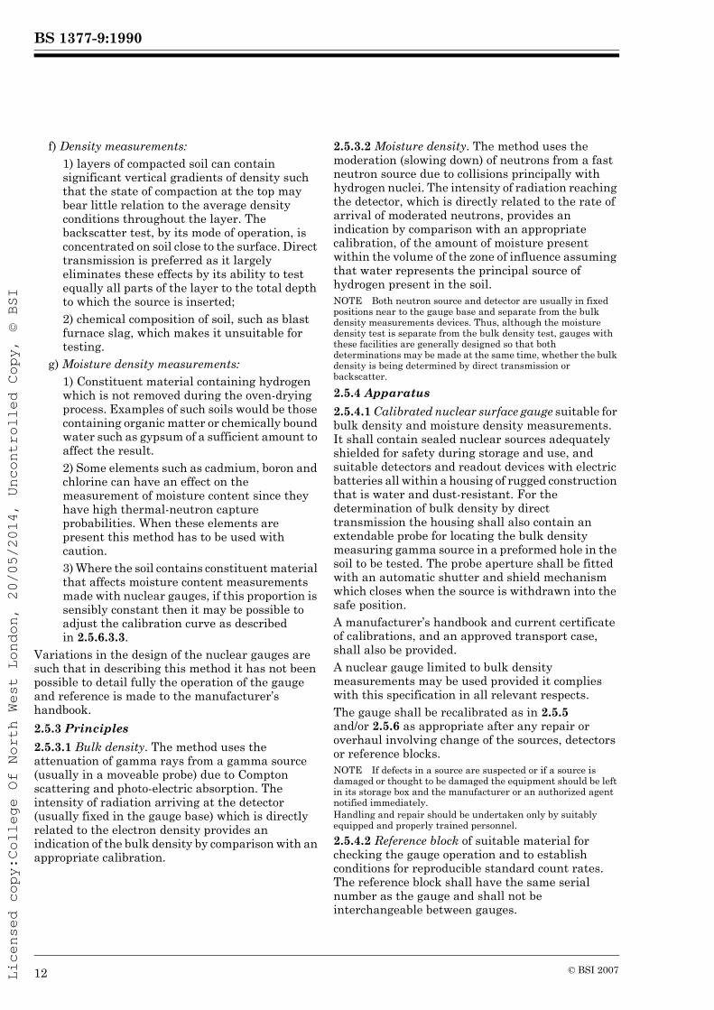
f) Density measurements:1) layers of compacted soil can contain significant vertical gradients of density such that the state of compaction at the top may bear little relation to the average density conditions throughout the layer. The backscatter test, by its mode of operation, is concentrated on soil close to the surface. Direct transmission is preferred as it largely eliminates these effects by its ability to test equally all parts of the layer to the total depth to which the source is inserted;2) chemical composition of soil, such as blast furnace slag, which makes it unsuitable for testing.
g) Moisture density measurements:1) Constituent material containing hydrogen which is not removed during the oven-drying process. Examples of such soils would be those containing organic matter or chemically bound water such as gypsum of a sufficient amount to affect the result.2) Some elements such as cadmium, boron and chlorine can have an effect on the measurement of moisture content since they have high thermal-neutron capture probabilities. When these elements are present this method has to be used with caution.3) Where the soil contains constituent material that affects moisture content measurements made with nuclear gauges, if this proportion is sensibly constant then it may be possible to adjust the calibration curve as described in 2.5.6.3.3.
Variations in the design of the nuclear gauges are such that in describing this method it has not been possible to detail fully the operation of the gauge and reference is made to the manufacturer’s handbook.2.5.3 Principles2.5.3.1 Bulk density. The method uses the attenuation of gamma rays from a gamma source (usually in a moveable probe) due to Compton scattering and photo-electric absorption. The intensity of radiation arriving at the detector (usually fixed in the gauge base) which is directly related to the electron density provides an indication of the bulk density by comparison with an appropriate calibration.
2.5.3.2 Moisture density. The method uses the moderation (slowing down) of neutrons from a fast neutron source due to collisions principally with hydrogen nuclei. The intensity of radiation reaching the detector, which is directly related to the rate of arrival of moderated neutrons, provides an indication by comparison with an appropriate calibration, of the amount of moisture present within the volume of the zone of influence assuming that water represents the principal source of hydrogen present in the soil.NOTE Both neutron source and detector are usually in fixed positions near to the gauge base and separate from the bulk density measurements devices. Thus, although the moisture density test is separate from the bulk density test, gauges with these facilities are generally designed so that both determinations may be made at the same time, whether the bulk density is being determined by direct transmission or backscatter.
2.5.4 Apparatus2.5.4.1 Calibrated nuclear surface gauge suitable for bulk density and moisture density measurements. It shall contain sealed nuclear sources adequately shielded for safety during storage and use, and suitable detectors and readout devices with electric batteries all within a housing of rugged construction that is water and dust-resistant. For the determination of bulk density by direct transmission the housing shall also contain an extendable probe for locating the bulk density measuring gamma source in a preformed hole in the soil to be tested. The probe aperture shall be fitted with an automatic shutter and shield mechanism which closes when the source is withdrawn into the safe position.A manufacturer’s handbook and current certificate of calibrations, and an approved transport case, shall also be provided.A nuclear gauge limited to bulk density measurements may be used provided it complies with this specification in all relevant respects.The gauge shall be recalibrated as in 2.5.5 and/or 2.5.6 as appropriate after any repair or overhaul involving change of the sources, detectors or reference blocks.NOTE If defects in a source are suspected or if a source is damaged or thought to be damaged the equipment should be left in its storage box and the manufacturer or an authorized agent notified immediately.Handling and repair should be undertaken only by suitably equipped and properly trained personnel.2.5.4.2 Reference block of suitable material for checking the gauge operation and to establish conditions for reproducible standard count rates. The reference block shall have the same serial number as the gauge and shall not be interchangeable between gauges.
12 © BSI 2007

BS 1377-9:1990
Licensed copy:College Of North West London, 20/05/2014, Uncontrolled Copy, © BSI
NOTE The reference block should be kept clean and free from adhering particles, which may cause a poor contact with the gauge and result in an erroneous standard count rate.
2.5.4.3 Gamma radiation monitor.2.5.4.4 Test area preparation equipment, i.e. suitable tools for levelling the ground at the site of the test, such as shovel, trowel, brush and straightedge.2.5.4.5 Steel drive pin and hammer and/or suitable auger with template to form and position the test hole for the direct transmission test for bulk density measurements. The drive pin should produce a hole up to 3 mm larger than the external diameter of the gauge probe.2.5.4.6 Gauge log to record standardization (see 2.5.7) and stability (see 2.5.8) test results.2.5.4.7 Calibration results. These may be in the form of charts and may also be stored in the memory bank of the readout system.2.5.4.8 Dry clean fine quartz sand for bedding gauge on uneven surfaces.2.5.5 Calibration for bulk density measurements2.5.5.1 Manufacturer’s bulk density calibration. This calibration shall initially be carried out in accordance with ASTM D29225). Every 24 months the manufacturer’s calibration shall be checked using not less than three of the standard density blocks as described in ASTM D2922.2.5.5.2 Initial site calibration for bulk density. Calibrate the nuclear gauge in accordance with this clause for each mode of operation to be used for the test and at each test depth if used in direct transmission. The calibration procedure will depend upon the nature of the measurement application. These categories are as follows:
a) ground investigation comparative tests;b) ground investigation absolute tests;c) compliance tests for compacted material.
1) Ground investigation comparative tests. These tests require no initial site calibration, provided that the.data obtained are used only for comparative purposes on the particular site. The test report shall clearly state that the comparative test method has been used and that no initial site calibration was carried out.
2) Ground investigation absolute tests. Carry out an initial test before using the gauge at any location or when any significant change of soil type occurs. Do this by selecting a suitable location and performing a minimum of three separate nuclear density gauge tests followed by a series of suitable alternative in-situ test methods, such as sand/water replacement or core cutter methods as described in 2.1 to 2.4. If each of the field tests varies by less than 3 % from the nuclear density gauge result then adjustment of the manufacturer’s calibration is not necessary. Where there is a difference of 3 % or greater then a soil calibration shall be made as described in 2.5.5.3 for the mode of operation to be used. Where this is to be by direct transmission the gauge shall be calibrated at each test depth. Two alternative calibration methods are given using either containers or in-situ tests. Normally for both modes of operation calibration by the separate container method is preferred.NOTE The alternative in-situ methods may produce data with an inherent scatter which itself exceeds 3 %. It is important therefore to carry out sufficient in-situ tests to provide reliable data. Where there is a doubt soil calibration using the container method should be carried out. (See 2.5.5.3.1.)3) Compliance tests for compacted material. Where the nuclear gauge is to be used for compliance tests on compacted material, carry out the initial site calibration using a single container test as specified in 2.5.5.3.1 prepared at the lower limit of compliance of bulk density plus or minus 2 %.
2.5.5.3 Soil calibration for bulk density. Carry out a minimum of five separate calibration tests on the selected soil as described below using a range of different bulk densities which fully cover the span of expected use with as uniform a spread as practicable. Two alternative methods are described.2.5.5.3.1 Calibration by the container method. Proceed as follows.
a) Select a suitable container (or containers) having sufficiently rigid walls and base not to deform when soil is placed and compacted within it, and a sufficient size not to change the observed count (or count rate) if made larger in any dimension.
5) See reference list of standards on inside back cover.
© BSI 2007 13

BS 1377-9:1990
Licensed copy:College Of North West London, 20/05/2014, Uncontrolled Copy, © BSI
NOTE Containers with internal plan dimensions of approximately 500 mm long by 380 mm wide have proved satisfactory for equipment presently available (1990). For direct transmission, the depth of the container can be matched to the sample depth for which the soil calibration is required; in this case the depth of the container should be equal to the appropriate hole depth referred to in 2.5.9.1. For calibration with the backscatter mode of operation, a minimum depth of 230 mm is adequate.b) Place the clean empty container on a level rigid base, measure the internal dimensions to the nearest 1 mm and calculate the internal volume. Determine the mass of the empty container if this is to be used to obtain the total mass of soil to be placed within the container.c) Prepare a block of selected soil within the container to a density within the required range (see note). Finish the top of the block level with the top of the container. From the known total mass of soil placed in the container and its internal volume calculate the bulk density of the soil.NOTE Care should be taken to avoid the occurrence of significant density gradients when filling the container except when the depth of the container is matched to the sampling depth of the nuclear gauge in the case of direct transmission testing. Variations in the method of preparation, other than of overall bulk density, may produce erroneous data and great care should, therefore, be taken in preparation. If there is any doubt the calibration should be checked using an alternative approved method.d) Within 1 h of filling the container measure the bulk density with the nuclear gauge in the same manner as described for making site measurements of bulk density and according to the mode of operation for which the calibration is being made.
2.5.5.3.2 Calibration by the in-situ method. Proceed as follows.
a) Carefully select an area for a minimum of five calibration tests in order to provide as close agreement as practicable to the range of densities likely to be found at the test location.b) Measure the in-situ bulk density with the nuclear gauge in the same manner as described for making site measurements of bulk density and according to the mode of operation for which the calibration is being made.c) Carry out at each calibration test location an appropriate alternative in-situ test method, such as sand/water replacement or core cutter method as described in 2.1 to 2.4 to determine an alternative bulk density measurement.
2.5.5.3.3 Derivation of the calibration. Proceed as·follows.
a) Plot the bulk densities obtained from the alternative in-situ tests or from the dimensions and masses of soil placed in the container(s) against the nuclear bulk density measurements.
b) Calculate the least-square best fit line from the data and obtain an adjusted bulk density from the equation:
Adjusted bulk density = bρn ± a (in Mg/m3)where
b and a are the slope and intercept respectively as determined in the least-square analysis;ρn is the nuclear gauge bulk density (in Mg/m3).
Use the results of the analysis to adjust the manufacturer’s calibration where this is incorporated in the gauge electronics.c) Repeat the calibration every 3 months when testing is to continue for a particular calibration for longer than this period.
2.5.6 Calibration for moisture density measurements2.5.6.1 Manufacturer’s moisture density calibration. This calibration shall initially be carried out in accordance with ASTM D3017. Every 24 months the manufacturer’s calibration shall be checked for the nuclear gauge.2.5.6.2 Initial site calibration for moisture density. Calibrate the gauge in accordance with this clause depending upon the nature of the measurement calibration. These categories are:
a) Ground investigation comparative tests.b) Ground investigation absolute tests.c) Compliance tests for compacted material.
1) Ground investigation comparative tests. These tests require no initial site calibration provided that the data obtained are used only for comparative purposes on a particular site. The test report shall clearly state that the comparative test method has been used and that no initial site calibration was carried out.2) Ground investigation absolute tests. Carry out an initial test before using the gauge at any location or when any significant change of soil type occurs. Do this by selecting a suitable location and performing a minimum of two separate nuclear gauge tests following the procedure as in 2.5.6.3, at different moisture densities spanning the range of expected use. For each nuclear gauge test determine the quantity of water present per unit volume of the soil from a standard bulk density measurement other than the nuclear gauge method, and the moisture content by the method described in BS 1377-2:1990.
14 © BSI 2007

BS 1377-9:1990
Licensed copy:College Of North West London, 20/05/2014, Uncontrolled Copy, © BSI
Compare the alternative density and moisture content results with the nuclear gauge moisture density measurements. If each of the results of the alternative tests varies by not more than 0.01 Mg/m3 of water from the nuclear gauge result, and some of the alternative test results are greater and some less than the nuclear gauge results, then adjustment of the manufacturer’s calibration is not necessary. Where the results of the alternative tests all lie in one direction some gauges include a facility for a constant adjustment.Where there is a difference between the previous calibration and the check points that is greater than 0.01 Mg/m3 of water carry out a soil calibration as described in 2.5.6.3. Two soil calibration procedures are given using either containers or in-situ tests. Normally the container method is preferred.NOTE The alternative in-situ test methods may produce data with an inherent scatter which itself exceeds 0.01 Mg/m3 of water. It is important therefore to carry out sufficient alternative tests to provide reliable data. Where there is a doubt the full soil calibration should be carried out as given in 2.5.6.3.3) Compliance tests for compacted material. Where the nuclear gauge is to be used for compliance tests on compacted material, carry out the initial site calibration using a single container of soil as specified in 2.5.6.3 prepared at the upper limit of compliance for moisture content and at the maximum achievable bulk density at that moisture content, plus zero or minus 2 % of the wet weight of the soil.
2.5.6.3 Soil calibration for moisture density. The procedures are similar to those described in 2.5.5.3 except that a minimum of three separate calibration tests shall be carried out on the selected soil using a range of different moisture densities which fully cover the span of the expected use. Two alternative methods are given.2.5.6.3.1 Calibration by the container method. Proceed as follows.
a) Select a suitable container (or containers) having sufficiently rigid walls and base not to deform when soil is placed and compacted within it, and a sufficient size not to change the observed count (or count rate) if made larger in any dimension.NOTE Containers with internal dimensions of approximately 600 mm long by 460 mm wide by 450 mm deep have proved satisfactory for equipment presently available (1990).
b) Place the soil in the container(s) as described in 2.5.5.3.1 b) and c) in a manner to provide a uniform bulk density and moisture density.c) Carry out the nuclear measurement following the principles described in 2.5.5.3.1 d).d) Calculate the bulk density of the soil block from the internal volume of the container and the mass of wet soil. Then take a representative sample of the wet soil in the container and determine the moisture content by the method described in BS 1377-2:1990.e) Calculate the moisture density, i.e. the mass of water present per unit volume of placed soil.
2.5.6.3.2 Calibration by the in-situ method. Proceed as follows, the procedure being similar to that described in 2.5.5.3.2. After the nuclear measurement calculate the moisture density of the soil in the same place by an alternative in-situ bulk density test method such as sand/water replacement or core cutter method, as described in 2.1 to 2.4, and the moisture content of the in-situ soil by the method described in BS 1377-2:1990.2.5.6.3.3 Derivation of the calibration. Proceed as follows.
a) Use the two sets of data on moisture density, i.e. the count ratio or moisture density measurement by the existing gauge calibration and the results of the alternative test methods to obtain the required calibration.b) The relation of the best fit for moisture density is normally linear. Use the results of the analysis to adjust the manufacturer’s calibration when this is incorporated in the gauge electronics.c) Where the new calibration points all lie uniformly on one side of the previous calibration, it may be due to the presence of chemically bound water in the soil. Some gauges include a facility to provide a constant adjustment of the result to suit such cases.d) Repeat soil calibrations for moisture density measurements every 3 months when testing is to continue for a particular calibration for longer than this period.
2.5.7 Gauge standardization procedure. Carry out the standardization of the gauge on the reference block for each type of measurement at the start and end of each day’s use. This procedure shall also be repeated after 8 h of continuous use, but may be carried out more frequently if appropriate. Retain a permanent record of these data. If the gauge is switched off repeat the standardization procedure.
© BSI 2007 15
BS 1377-9:1990
Licensed copy:College Of North West London, 20/05/2014, Uncontrolled Copy, © BSI
NOTE All nuclear gauges are subject to long-term ageing of the sources (radioactive decay), electronic components and the detectors. Local geography may cause background radiation to vary, which can change the gauge performance. Gauges are therefore calibrated in terms of a ratio of the measurement count rate for each radioactive source to a count rate made on a reference block.The procedure is as follows:
a) Switch on the gauge and allow for normalization if required in accordance with the manufacturer’s handbook. This period will usually be not less than 15 min. If the gauge is to be used either continuously or intermittently during the day, do not switch the gauge off. Perform the test with the gauge located at least 7 m away from other nuclear gauges and at least 1.5 m from any large structure which may affect the gauge readings.
b) Place the gauge on the reference block and ensure that the bulk density gamma source is correctly located. For each type of measurement, i.e. bulk density and moisture density, take at least four repetitive readings of the standard count rate each of 1 min period and calculate the mean value. Alternatively if available on the gauge, one measurement over a period of 4 min or more is acceptable. Either constitutes one standardization check.c) Make a record of the results of each standardization check with the date of the measurements in the gauge log in order to retain a continuity of the results.d) Check whether the arithmetical mean value in each case is within the limits set by the following equation and record the value of Ns in the gauge log, using the equation:
where
e) If Ns is within the limits permitted above, the Ns can be used to determine the count rate ratios for the current day’s use of the gauge.
f) If Ns is outside the permitted limits repeat at least twice more the procedure for determining the average standard count rate. If all three or two of the three determinations are outside the acceptable limits, withdraw the gauge from service until the fault is rectified.g) If the standardization at the end of the working period gives values outside the permitted limits all results within that working period are invalidated.
2.5.8 Gauge stability procedure. Carry out the gauge stability check for each type of measurement at least once a month when in general daily usage and at least once every 3 months otherwise.The procedure shall be as follows.
a) Follow the gauge standardization procedure in 2.5.7 except that a series of at least 16 repetitive readings of the standard count rate, each of a 1 min period, are carried out with the gauge on the reference block for each type of measurement. Do not move the gauge during this process.b) Separately record each of the measurements for each radioactive source in the gauge log with the date of the measurements.c) Determine the standard deviation (SD) and determine the average value of each series of repetitive measurements.d) Check that each stability ratio, expressed as the standard deviation divided by the square root of the average value, lies within the manufacturer’s quoted range for the gauge. Take into account any prescale value used and record the results in the gauge log.e) Where either of the stability ratios falls outside the manufacturer’s specified range or the trend in successive checks is erratic withdraw the gauge from service until the fault is rectified.
2.5.9 Test procedure. The following particulars are subdivided according to the mode of operation used for bulk density measurements. The addition of moisture density measurements, with gauges including this facility, may be taken at the same time as the bulk density measurements in either bulk density mode of operation of the gauge. Where moisture density, as the mass of water per unit volume, is separately required follow the procedure for a backscatter test omitting the operations concerning bulk density but return the bulk density measurement gamma source inside its shielded housing with the shutter closed.
Ns is the average value of the current standard count rate;
No is the average of the past four values of Ns taken prior to use;
Pc is the amount of prescale applied to the detector counts prior to display. The manufacturer should supply this value. If no prescale is built into the gauge the value is 1;
Ns=No 2.0NoPc-------±
16 © BSI 2007

BS 1377-9:1990
Licensed copy:College Of North West London, 20/05/2014, Uncontrolled Copy, © BSI
2.5.9.1 Direct transmission procedure for bulk density. Proceed as follows.
a) Standardize the gauge as described in 2.5.7.b) Select and prepare a test location at which the bulk density and moisture density are to be measured.Perform the test with the gauge located at least 7 m away from other nuclear gauges and normally at least 1.5 m from any large structure which may affect gauge readings.When having to make a test within 1.5 m of a trench wall or structure and the gauge moisture density is to be used to determine dry density, then, in order to take account of the effects of reflected radiation, it is necessary that a moisture count over a 1 min period be made with the gauge placed on the reference block within 10 mm of the test position for each such test and to use the same orientation as for the tests. Moreover the gauge should always be kept at least 150 mm clear of any vertical projection. Calculate the difference between this count and the reference moisture count obtained as described in 2.5.7 and use the moisture offset value so obtained to adjust all subsequent moisture counts made at this location. Follow the procedures given in gauge manufacturer’s handbook to incorporate the moisture offset value.c) Remove extraneous material from the test position, which shall be essentially flat and free of depressions.d) Using the template as a guide, drill or drive a hole for the probe to the appropriate depth. The depth of the hole may need to be greater than the depth over which the bulk density is to be determined. (Consult the manufacturer’s handbook for advice on the appropriate hole depth.) Mark the soil surface in order to locate the gauge correctly with respect to the position of the hole for the probe.e) Place the gauge on the test location and ensure there is good overall contact between the base of the gauge and the soil being tested. When in doubt, maximize contact between gauge base (which shall be kept clean and free of adhering particles without bringing the hands in contact with the base) and surface by using small quantities of fine dry sand or fines of material under test to fill small surface voids. This material shall not form an added layer.f) Insert the probe to the selected depth according to the manufacturer’s handbook.
g) Pull the gauge in the direction that will bring the probe against the side of the hole, closest to the detector location in the gauge housing.h) Follow the gauge manufacturer’s handbook to obtain a gauge bulk density reading, and if required a gauge moisture density reading, both with a minimum test period of 1 min using the built-in timer.NOTE In order to minimize radiation effects move away from the gauge when not operating it and during counts.If desired, the gauge may be rotated about the axis of the probe and further measurements made. Normally for two determinations the gauge is rotated through 180° and the two results averaged. Alternatively the volume of soil measured can effectively be increased by repeating the test at immediately adjacent (vertically or horizontally) locations and averaging the two results.If the test is repeated in a vertically adjacent location, and the results are to be averaged, the top of the second test shall be at the level of the depth selected for the insertion of the probe in the first test.i) Take the field readings of bulk density and moisture density at the test location, and record them where necessary.Adjust the field values if necessary using the calibration charts. Some gauges contain microprocessors capable of storing a user-determined calibration which automatically corrects the displayed data.j) Retract the extendable probe into the housing, ensure the shutter is closed and check that the radioactive source is safely housed. Use the gamma radiation monitor to establish that the radiation profile is within the limit set by the manufacturer’s handbook.
2.5.9.2 Backscatter procedure for bulk density and moisture content. Proceed as follows.
a) Follow the procedure given in 2.5.9.1 a), paragraphs 1 and 2 b), d) and f).When having to make a test within 1.5 m of a trench wall or structure in order to take account of the effects of reflected radiation it is important that a second gauge standardization procedure as given in 2.5.7 a) and b) is made within 10 mm of the test position for each such test and to use the same orientation as for the tests. Moreover the gauge should always be kept at least 150 mm clear of any vertical projection.b) Follow the gauge manufacturer’s handbook to obtain a gauge bulk density reading and gauge moisture density reading, both with a minimum test period of 1 min using the built-in timer.
© BSI 2007 17

BS 1377-9:1990
Licensed copy:College Of North West London, 20/05/2014, Uncontrolled Copy, © BSI
NOTE In order to minimize radiation effects move away from the gauge when not operating it and during counts.If desired, the gauge may be rotated about the axis of the probe and further measurements made. Normally for two determinations the gauge is rotated through 180° and the two results averaged.Alternatively the volume of soil measured can effectively be increased by repeating the test at immediately adjacent locations and averaging the two results.c) Take the field readings of bulk density and moisture density at the test location and record them where necessary.Adjust the field values if necessary using the calibration charts. Some gauges contain microprocessors capable of storing a user-determined calibration which automatically corrects the displayed data.d) Retract the extendable probe into its housing, ensure the shutter is closed and check that the radioactive source is safely housed. Use the gamma radiation monitor to establish that the radiation profile is within the limit set by the manufacturer’s handbook.
2.5.10 Calculations and expression of the results2.5.10.1 Dry density. Calculate the dry density, ρd (in Mg/m3), from the equations:
a) for nuclear gauge determinationsρd = ρ – W
where
b) for laboratory determination of moisture content
where
2.5.10.2 Moisture content. Calculate the moisture content, w (as %), from the equation:
where
2.5.11 Test report. The test report shall affirm that the test was carried out in accordance with this Part of this standard and shall contain the following information.
a) Method of test used.b) The in-situ bulk density of the soil (in Mg/m3) to the nearest 0.01 Mg/m3, and mode of operation of the gauge.c) Where applicable, the moisture content (in %) to two significant figures.d) Where applicable, the dry density of the soil (in Mg/m3) to the nearest 0.01 Mg/m3.e) Nature of measurement application (2.5.5.2 and/or 2.5.6.2).f) The model and serial number of the gauge.g) The information required by clause 9 of BS 1377-1:1990.
3 In-situ penetration tests3.0 IntroductionThis clause describes methods for determining three different types of penetration resistance of soil. All are empirical methods of testing the strength of soil at various depths below a particular location. The cone penetration test and the dynamic probing test are usually carried out independently of the borehole and other tests; the former being the more precise while the latter uses much simpler apparatus. The standard penetration test is for use in a borehole.3.1 Determination of the penetration resistance using the fixed 60° cone and friction sleeve (static cone penetration test CPT)3.1.1 General. This method covers the determination of the resistance of soils in situ to the continuous penetration at a slow uniform rate of a series of push rods having a cone at the base, and measuring continuously or at selected depth intervals the penetration resistance of the cone and, if required, the local friction resistance on a friction sleeve and pore pressure in the vicinity of the cone and sleeve.
ρ is the bulk density of the soil (in Mg/m3) determined with the nuclear gauge;
W is the moisture density, i.e. the mass of water per unit volume of soil (in Mg/m3) determined with the nuclear gauge.
ρ is the bulk dentisy of the soil (in Mg/m3) determined with the nuclear gauge;
w is the moisture content of the soil (in %) as determined by the method given in BS 1377-2:1990.
ρd100ρ
100 w+---------------------=
w 100 Wρ W–-----------------=
W is the moisture density, i.e. the mass of water per unit volume of soil (in Mg/m3) determined with the nuclear gauge;
ρ is the bulk density of the soil (in Mg/m3) determined with the nuclear gauge.
18 © BSI 2007

BS 1377-9:1990
Licensed copy:College Of North West London, 20/05/2014, Uncontrolled Copy, © BSI
This method requires the use of a penetrometer tip with electrical sensors as defined in 3.1.2.4, thereby permitting continuous readings and an instant read-out. This is not intended to prohibit the use of the older type of mechanical penetrometer, where readings are taken through inner push rods thrusting against load capsules mounted on the thrust machine. It should be noted that the mechanical penetrometer does not give precisely the same readings as would be obtained by the electrical penetrometer tip, which is now specified as standard. In submitting reports, the type of penetrometer and penetrometer tip which has been used should always be given.The requirements of Part 1 of this standard, where appropriate, shall apply to the test methods described in this clause.3.1.2 Apparatus. The complete apparatus, known as the penetrometer, shall consist of the parts described in 3.1.2.1 to 3.1.2.11.3.1.2.1 Penetrometer tip. The penetrometer tip shall comprise a cylindrical terminal body which is mounted on the lower end of the push rods. The tip shall contain: a) the cone at the base, b) close above the base externally, the friction sleeve, where fitted, c) internally, the sensing devices for measurement of the cone and sleeve resistances, d) internally an inclinometer where fitted (see note) and e) piezometric sensors where fitted.The axes of the cone friction sleeve, if included, and the body of the penetrometer tip shall be coincident.The diameter of the penetrometer tip shall nowhere be 0.3 mm smaller or 1 mm larger than the diameter of the base of the cone. In the case of a penetrometer tip with a friction sleeve, no part of the penetrometer tip shall project beyond the sleeve diameter. Seals shall be fitted at the ends of the sleeve and at the base of the cone to prevent entry of soil particles.The gap width between base of cone and base of friction sleeve shall not exceed 5 mm except when occupied by another sensor in which case the overall width, including the sensor, shall not exceed 15 mm. The external diameter, except where seals are fitted, shall correspond to the diameter of the cone base.Examples of suitable penetrometer tips are shown in Figure 8.NOTE Where the ground conditions are expected to cause the penetrometer tip to become inclined, or where penetrations in excess of about 20 m are to be made, it is desirable for a two-directional inclinometer to be incorporated in the penetrometer tip to indicate its inclination.
3.1.2.2 60° cone. The cone of hard-wearing material shall consist of a lower externally shaped conical part with a nominal base diameter of 35.7 mm (nominal base area 1 000 mm2) and an apex angle of 60°, with an upper cylindrical extension limited to 5 mm. Figure 9 shows the permitted tolerances including allowances for wear, surface finish and typical manufacturing dimensions.3.1.2.3 Friction sleeve. An independent cylindrical unit, which shall nowhere be smaller than the external diameter of the cone base or 0.35 mm larger than the external diameter of the cone base. The length shall be such that its external peripheral area is 150 × 102 mm2. Figure 10 shows the permitted tolerances, including allowances for wear, surface finish and typical manufacturing dimensions.3.1.2.4 Cone and friction sleeve sensors. The sensing devices for measuring the cone and frictional resistance shall be constructed in such a way that possible eccentricity of these resistances cannot influence the readings. The sensing device fitted to the cone shall measure only the axial force imposed on the cone by the soil below it. The device fitted to the friction sleeve shall measure only shear stresses and not normal stresses. Electronic sensors shall be temperature-compensated.3.1.2.5 Piezometric sensor. If required, pore pressures may be measured at the penetrometer tip. The sensor shall be capable of measuring water pressure to an accuracy of ± 5 % down to a limit of ± 0.2 m of water and shall be protected against the entry of soil particles by a filter of wear-resistant material.NOTE The position and type of piezometric sensor has not been specified as these will vary according to what is to be measured and the soil type. Two sensors at different locations may be required.3.1.2.6 Push rods. Push rods shall consist of steel cylindrical tubes, each 1 m nominal effective length, screwed or attached together to bear against each other, and with sufficient wall thickness, to form a rigid-jointed series with a continuous straight axis (see Figure 10). The minimum quality of the steel shall correspond to that specified for upset drill rods in BS 4019-1. The bore of the rods may be used for conveying the measuring signals from the sensing devices to the measuring equipment at the surface.The external diameter of the push rods shall be such that it does not influence measurements at the penetrometer tip. Normally the external diameter of the push rods is 36 mm ± 1 mm. Smaller external diameters may be used continuously or at intervals along the string to reduce soil friction acting on the push rods providing that the distance between commencement of the smaller diameter push rods and the cone base shall be at least 1 m.
© BSI 2007 19

BS 1377-9:1990
Licensed copy:College Of North West London, 20/05/2014, Uncontrolled Copy, © BSI
The deflection from a straight line through the ends at the mid-point of a 1 m long push rod shall not exceed a) 0.5 mm for the five lowest push rods and b) 1 mm for the remainder. For any pairs of joined push rods the deflection from a straight line through the mid-points of the rods at the joint shall also not exceed these limits. The push rods shall be checked after every test in ground conditions known to be conducive to rod bending, e.g. large depths of very soft soils over hard layers, or soils containing cemented zones or coarse material. Rods with excessive deflections shall not be reused until straightened.NOTE Curvature and eccentricity may be simply observed by coupling the rod with a straight rod and rolling the latter on a plane surface.3.1.2.7 Friction reducer. A ring, fixed on the outside of the push rods, with an external diameter larger than the base of the cone, to reduce soil friction acting on the push rods.The position of this ring on the push rods shall be more than 400 mm above the base of the cone and at least 200 mm above the top of the friction sleeve.3.1.2.8 Push rod guides. Guides shall be provided for the part of the push rods protruding above the soil, and for the rod length exposed in water, in order to prevent buckling when the required penetration pressure increases beyond the safe limit for the exposed upstanding length of push rods.3.1.2.9 Calibrated measuring equipment. Direct readings of the resistance of the cone and local friction sleeve (if fitted), and of the piezometric sensor (if fitted) shall be available individually for display throughout a test and shall supplement tape or other recording techniques where provided.3.1.2.10 Thrust machine. The thrust machine shall be constructed such that a) the reaction providing the thrust does not influence the resistance, by having the screw anchors or ballast supports at a sufficient distance from the push rods, b) the machine shall not move relative to the soil surface by more than 0.5 mm per kN of thrust during the pushing action, c) the machine shall be capable of a continuous thrust stroke of at least 1 m, d) the rate of penetration during driving of the penetrometer tip shall be capable of being controlled at a rate of 20 ± 5 mm/s and thereafter maintained at a constant rate during the entire stroke even if readings are taken intermittently. (see note at end of 3.1.4.7), e) means shall be provided to thrust the push rods vertically into the ground and when necessary provide support for the push rod guides.3.1.2.11 Spirit level to observe verticality of the thrust machine and the push rods and their deviation.
3.1.3 Calibrations3.1.3.1 Initial calibration before use and recalibration records shall be retained in the penetrometer calibrations register for each individual item of measuring equipment, referred to by its reference number. A copy of the current calibration certificates recording the calibration or recalibration results, and dates when made, shall accompany each measuring device during its use on site, and be available for inspection.3.1.3.2 Measuring equipment for resistances. Calibration of each force-measuring instrument shall be made before and after every 2 000 m of use, and after a repair or overhaul.3.1.3.3 Grading of resistance-measuring equipment. Taking into account all parts of the systems including the sensors, signal transmission, signal conversion, recording and display together with the maximum required compensations to be provided for temperature variations and eccentricity of stress on the cone or sleeve, the precision shall be not more than the larger of the following values:
5 % of the actual applied resistance;1 % of the maximum value that is permitted for the range of the equipment.
This overall grading shall be verified in accordance with BS 1610, but the grading limits specified therein shall be disregarded.3.1.3.4 Piezometric sensors. Calibrations shall be made before and after every 2 000 m of use, and after a repair or overhaul. The precision requirements are as specified in 3.1.2.5.3.1.3.5 Linear recordings. Where equipment is incorporated in the penetrometer for recording the penetration of the tip this apparatus shall be calibrated before and after every 2 000 m of use, and after a repair or overhaul. The precision requirements shall be better than 0.1 m.3.1.4 Procedure3.1.4.1 The principle to be followed shall be that of continuous testing in which the resistance measurements are made while all elements of the penetrometer tip are moving downwards simultaneously and at the standard rate of penetration.3.1.4.2 Pretest checks. Make the following inspections before each test and replace defective items of apparatus with others in sound condition.
a) Push rods. Stand the push rod vertically, spin it, and observe whether it wobbles while it is rotating. If there is wobble discard the rod or check it for compliance with 3.1.2.6.
20 © BSI 2007

BS 1377-9:1990
Licensed copy:College Of North West London, 20/05/2014, Uncontrolled Copy, © BSI
b) Cone and friction sleeve. Check that the wear does not exceed the permitted tolerances (see 3.1.2.2 and 3.1.2.3).c) Seals between different elements of the penetrometer tip. Check for wear and remove any particles of soil present that might interfere with the measurements.d) Electric cable for signal transmission from the penetrometer tip. Check for sound outer cover and ensure it is already threaded through sufficient push rods not to affect continuous testing.
3.1.4.3 Selection of test location. In order to obviate disturbance locate the test position at least 1 m from previously performed cone penetration tests not more than 10 m deep or at least 1.5 m where the depth exceeded 10 m, or 25 borehole diameters from previous boreholes.3.1.4.4 Piezometric sensors. Ensure that there is full saturation of the filter and other spaces of the measuring system prior to each test.NOTE Impregnation with silicon oil, glycerine or glycerine and water has been found to reduce re-entry of air prior to penetrating below the water table.3.1.4.5 Verticality. Erect the thrust machine to provide thrust on the push rods in as near a vertical direction as practicable. The maximum deviation of the thrust direction from the vertical shall not exceed 2 %.3.1.4.6 Penetration. After joining the penetrometer tip to the leading push rod place them in the machine so that their axis coincides with the thrust direction.Where a friction reducer is used ensure that it is located as described in 3.1.2.7.Check that verticality is maintained throughout the test by observing the verticality of the upstanding push rod immediately after adding an additional push rod. Discontinue the test if it exceeds the specified limit, and recommence the test at least 1 m from the discarded test location.Use the push rod guides when the required penetration pressure begins to exceed the buckling resistance of the upstanding length of the push rods and thereafter keep them in use to the end of the test.Complete each penetration test in one continuous operation to the full depth required. Record the duration of abnormal delays beyond 30 min at the depths to which they correspond. Stoppages in which the delay exceeds 2 h shall mean that the test is completed at that depth and a separate test shall be used if a greater depth is to be tested.3.1.4.7 Rate of penetration. The rate of penetration whether or not readings are being taken shall normally be 20 ± 5 mm/s.
NOTE In hard or very compact ground, especially at depth, it may not be possible to achieve the standard rate of penetration.3.1.4.8 Data for site record and the intervals of measurements. Measure and record the following:
either:a) the axial force (Qc) acting on the cone (in kN); andb) the frictional force (Qs) acting on the sleeve (in kN);
or direct measurements when machine facilities permit of:
c) the cone resistance (qc) (in MPa) (see 3.1.5.1); andd) the local unit side friction resistance (fs) (in MPa) (see 3.1.5.2);
and when required:e) the pore water pressure (u) acting on the piezometric sensor (in kPa); and/orf) the inclinometer value (in degrees or radians).g) the depth of the cone base below the ground surface corresponding to the above measurements. Measure the depth to an accuracy of at least 100 mm.
Take a continuous series of measurements if possible, except for the inclinometer, otherwise take readings at linear intervals that do not exceed 200 mm.NOTE A presentation of inclinometer values at 1 m intervals should normally be adequate.Note sounds from, or unusual vibrations of, the push rods, (representing indications of the presence of coarse material or obstructions), and note the depths corresponding to when they occurred.Record any unusual event during the test including the depths at which the push rods may have been extracted over a limited height in order to break the lateral resistance, and then been pushed back into the soil.3.1.4.9 Post-test checks and records. Check and record the following at the end of each test.
a) Immediately upon completion of each test, when the resistance measuring equipment is unloaded, record the reading for both the cone and friction sleeve if fitted and used.b) Inspect the cone, sleeve, seals and piezometers where fitted, for damage and wear since the commencement of the test.Inspect the push rods for alignment and damage.
© BSI 2007 21

BS 1377-9:1990
Licensed copy:College Of North West London, 20/05/2014, Uncontrolled Copy, © BSI
Where wear of the sleeve or cone has taken place during the test such that either has reached a state where during the test it should have been replaced, the test shall remain valid but shall include in the reports a statement describing the condition of the sleeve and cone at the end of the test.c) Record, where possible, the depth to the water level in the hole after withdrawal of the penetrometer tip, or the depth at which, the hole collapsed.d) Record whether the test hole has been backfilled, and if so by which method.e) Record the identification number of the penetrometer tip used for the test.f) Record the dates and reference numbers of the calibration certificates for the measuring devices.g) Record the name of the operator in charge of the crew which performed the test.
3.1.5 Calculations and expression of the results3.1.5.1 Cone resistance. Calculate the cone resistance, qc (in MPa), from the equation:
where
3.1.5.2 Local unit side friction resistance. Calculate the local unit side friction resistance, fs (in MPa), from the equation:
where
3.1.5.3 Friction ratio and friction index. Calculate the friction ratio (Rf) and the friction index (If) for measurements of the cone resistance (qc) and local unit side friction resistance (fs) at the same depth i.e. when the cone was at the level corresponding to the mid-point of the sleeve.
Friction ratio. Calculate the friction ratio, Rf (in %), from the equation:
3.1.6 Test report6). The report shall affirm that the test was carried out in accordance with this Part of this standard and shall contain the following information.
a) The method of test used.b) Graphic representations with respect to the depth of the following measurements:
cone resistance (qc) (in MPa);local unit side friction resistance (fs) (in MPa);friction ratio (Rf): horizontal axis;pore water pressure (u): horizontal axis, where appropriate.
c) Readings of the inclinometer, if taken, beyond a limit to be specified.d) The capacity and type of the penetrometer used.e) The type of resistance-measuring system used.f) The type of the penetrometer tip and cone used and the capacities of the different resistance-measuring devices used and their conditions with respect to wear.g) If piezometric sensors are used, their position and the type of filter.h) The depth over which a friction reducer or push rods with reduced diameter has been used.i) The depth at which push rods have been partly withdrawn in order to reduce the side friction resistance.j) Details of any unusual event or abnormal interrruption to the test.k) Observations on sounds from or unusual vibrations of the push rods and the depths corresponding to when they occurred.l) The depth to the water level in the hole remaining after withdrawal of the penetrometer tip or the depth at which the hole collapsed.m) Whether or not the test hole was backfilled.n) The information required by clause 9 of BS 1377-1:1990.
3.2 Determination of the dynamic probing resistance using the 90° cone (dynamic probing DP)The DP method is given in BS EN ISO 22476-2.
Qc is the axial force acting on the cone (in kN);Ac is the area of the base of the cone (in mm2).
Qs is the frictional force acting on the sleeve (in kN);
As is the external surface area of the sleeve (in mm2).
qcQcAc------⎝ ⎠⎛ ⎞ 103=
fsQsAs------⎝ ⎠⎛ ⎞ 103=
6) See form 9(d) of Appendix A.
Rffsqc-----⎝ ⎠⎛ ⎞ 100=
22 © BSI 2007

BS 1377-9:1990
Licensed copy:College Of North West London, 20/05/2014, Uncontrolled Copy, © BSI
3.3 Determination of the penetration resistance using the split-barrel sampler (the standard penetration test SPT)The SPT method is given in BS EN ISO 22476-3.
4 In-situ vertical deformation and strength tests4.0 IntroductionThis clause decribes four methods for investigating in-situ strength and load settlement characteristics of soil. The plate loading test (4.1) and the shallow pad maintained load test (4.2) are particularly suited for the design of foundations or footings for buildings where it is considered that the mass characteristics of the soil would differ significantly from the results of laboratory tests, or where more precise values of settlement are required. The in-situ CBR (4.3) is generally concerned only with pavement design and the control of subgrade construction of soils with a maximum particle size not exceeding 20 mm. The determination of the vane shear strength of weak intact cohesive soils is described in 4.4.4.1 Determination of the vertical deformation and strength characteristics of soil by the plate loading test4.1.1 General. This method covers the determination of the vertical deformation and strength characteristics of soil in situ by assessing the force and amount of penetration with time when a rigid plate is made to penetrate the soil. Uses are to evaluate the ultimate bearing capacity, the shear strength and deformation parameters of the soil beneath the plate without entailing the effects of sample disturbance. The method may be carried out at the ground surface, in pits, trenches or adits, and at depth in the bottom of a borehole.The requirements of Part 1 of this standard, where appropriate, shall apply to the test methods described in this clause.4.1.2 Preliminary considerations. The form of apparatus and the testing procedure selected shall provide a safe method for conducting the test. Before it is possible to select the apparatus and plan the test procedure the following information is required:
a) an estimate of the expected strength and deformation characteristics of the soil to be tested in order to judge the required loading and the size of the apparatus;b) the elevation of the loading plate with respect to the loading frame and whether the plate is to be in an open position or in a borehole;
c) the parameters to be determined and their required precision (see 4.1.6.4.1 and 4.1.6.4.2). In the case of a constant rate of penetration test the rate of penetration and its tolerance limits;d) the size of loading plate to be used. The plate size shall be as large as practicable taking into account the soil fabric and having regard to the amount of reaction required and the means of mobilizing it, the magnitude of the other apparatus and the size of pit or borehole required;NOTE When evaluating the shear strength of fissured clays the plate diameter should be at least 300 mm and more than five times the average spacing between fissures where practicable. When testing granular soil the plate diameter should exceed at least five times the nominal size of the coarsest material generally present.
e) the maximum reaction load, the range of loads to be measured and how the total load is to be provided;f) the settlement range to be measured and the accuracy required.
4.1.3 Apparatus4.1.3.1 General. The particular form of each item in the following list of apparatus is not fixed and shall be determined in accordance with the degree of precision required and the considerations given in 4.1.2.4.1.3.1.1 A loading plate of rigid construction. The plate shall be rigid and nominally flat on the underside. The top shall contain a guide to locate the loading column, particularly where the test is to be in a borehole. The longitudinal axis of the loading column and the centre of the plate shall be coincident and the contact shall be such that any tendency for the plate to tilt is resisted. A ball seating shall not be permitted.The plan area of the plate shall be determined within ± 1 %.4.1.3.1.2 Reaction loading system. Provision of the reaction load may be made in several different ways including by kentledge, such as water in tanks or concrete blocks, by tension piles or by jacking against an existing reaction such as a structure. In all cases the reaction load or its supports shall be placed sufficiently far from the proposed test position so as to reduce the influence on the results to a tolerable level. (See note 1.)Care shall be taken to ensure that the reaction load remains stable throughout the test without the possibility of load tilting or collapsing. (See note 2.)
© BSI 2007 23

BS 1377-9:1990
Licensed copy:College Of North West London, 20/05/2014, Uncontrolled Copy, © BSI
The loading column shall be of sufficient strength to prevent undue buckling under the maximum load and in the case of borehole tests shall be well clear of the borehole walls.NOTE 1 In the case of tension piles the normal practice is for their centres to be at least three times the plate diameter from the centre of the plate.NOTE 2 In addition to the reaction load it will normally be necessary to provide a loading frame, a loading column and a hydraulic jack or other appropriate type of load measuring device.
4.1.3.1.3 Calibrated force measurement system. To obtain the required accuracy it may be necessary to have more than one force-measuring device to cover the load range desired up to the defined maximum reaction load. (See 4.1.2. e).)4.1.3.1.4 Deformation measurement system. The deformation measurements shall be made to the required accuracy, independently of the loading column and from a datum independent of the other components of the test apparatus. Where a dial gauge or other measuring device is used in the centre of the plate, a reference beam may serve as the datum. Alternatively, levelling directly on to the plate may be adopted. When the test is in an excavation or borehole a separate reference column or invar tape shall be used to project the measurements to the plate.All settlement devices, e.g. dial gauges, shall be readable to ± 0.05 mm.4.1.3.1.5 Temperature gauge and thermo-couple system. When temperature measurements are specified a thermometer readable to 0.5 °C with the equivalent accuracy and covering the temperature range expected during the test shall be provided. When, due to the duration of the test, changes in temperature occur which could affect the level of the deformation measuring systems, such as in the case of incremental or maintained load tests, a thermo-couple system shall be provided to monitor the temperature of the reference beam and its other components likely to be affected.NOTE The effects of temperature on the distortion of the reference system are particularly important where it is required to measure small settlements. Precise levelling may be better when temperature effects are likely to be significant. The effect of different air temperatures on the load measurement devices also needs to be taken into account.
4.1.3.1.6 Test area preparation equipment. Suitable primary excavation equipment to penetrate rapidly close to the test level, such as mechanical diggers or boring equipment, including the casing, will be required. Temporary ground support may be necessary. When the test is to be carried out below groundwater level in permeable ground a system of wells outside and below the test position will usually be necessary.
NOTE In favourable circumstances when the seepage is small and the test is to be made in a borehole it may be possible to use a system of seals in the casing.
For exposing undisturbed soil at the test level select suitable hand digging tools such as a sharp-edged spade, trowel, hand brush and dust pan. Also provide a straight steel cutting edge, spirit level and measuring tape for preparing a flat level test area of sufficient size for the loading plate.4.1.3.1.7 Mixing equipment for quick setting plaster if used.4.1.3.1.8 Levelling equipment, readable to 0.1 mm and a stable datum when specified. The levelling staff shall have a bubble attached to it so that the verticality of the staff can be checked.4.1.3.1.9 Field dry density test apparatus, when specified, complying with clause 2 of this standard and suitable for the soil type expected to be tested.4.1.3.1.10 Containers for disturbed and undisturbed samples, suitable for the soil type expected to be tested.4.1.4 Materials4.1.4.1 Quick setting gypsum plaster for tests on cohesive soils.NOTE High strength gypsum plaster is needed. A suitable plaster mix consists of 2½ parts by weight of quick setting gypsum plaster of the alpha hemi-hydrate type to 1 part of cold water. This may be poured from a bucket. The initial set occurs after about 15 min from first mixing. A wet strength of about 30 000 kPa is reached in about 1 h. Normally two or three buckets full are required per test depending upon the plate size.
4.1.4.2 Clean dry sand for tests on granular soils.4.1.5 Calibration4.1.5.1 Calibrated force measurement. For high precision tests reverification of the calibration shall be carried out before and after each usage in the field. The temperature shall be recorded during these calibrations and the effects of variations shall be recorded within the range of temperature to be expected during the test.4.1.5.2 Deformation measurement. Instruments, used for measuring deformations, such as levelling equipment shall be maintained in adjustment according to manufacturer’s instructions.
24 © BSI 2007

BS 1377-9:1990
Licensed copy:College Of North West London, 20/05/2014, Uncontrolled Copy, © BSI
4.1.6 Procedure4.1.6.1 Primary excavation. Excavate to the test level as quickly as practicable to minimize the effects of stress relief, particularly when in cohesive soils. Install temporary ground support as necessary, particularly if persons are to enter the excavation to work (see note 1). Where the test is to be made below the groundwater level in permeable ground, install the equipment for water lowering and lower the water level before the excavation reaches the water table in order to prevent ground disturbance. (See note 2.)Review the method of excavation when within about 0.5 m of the test level in order to ensure that the remaining soil is removed by careful means to minimize local disturbance at the test level prior to its preparation.NOTE 1 The object is to place the plate and make the test on soil that is as undisturbed as possible and not significantly affected by opening of discontinuities, wetting or climatic change such as frost action.NOTE 2 When forming the primary excavation in boreholes, casing is normally essential especially near the surface to keep debris and water out of the hole. Where the ground at depth is self-supporting deeper casing may be omitted for constant rate of penetration tests subject to safety requirements, but for incremental loading tests, where the duration is generally longer, casing should extend to the bottom of the hole in order to minimize inward seepage of groundwater with consequent weakening of the soil conditions. Use preferably an auger in boreholes with clays when within about 0.5 m of the test level and then change to a flat-bottomed bucket auger to produce a flat-bottomed hole at the test level. The diameter of the borehole for a depth equivalent to one plate diameter should aproximate to the diameter of the plate.
4.1.6.2 Preparation at test level. Carefully trim off and remove all loose material and any embedded fragments so that the area for the plate is generally level and as undisturbed as possible. Hollows shall not be infilled with soil.For tests on cohesive soils proceed as soon as possible thereafter to pour and spread the paste of the quick-setting plaster to obtain a level surface not more than 15 mm to 20 mm thick. Immediately the paste is spread, bed the plate.For tests on granular soils fill any hollows with clean dry sand to produce a level surface on which to bed the plate.The final preparation of the test level in boreholes shall be done if possible by hand for deformation modulus measurements.When carrying out manual operations in a pit or the base of a borehole comply with BS 5573.When lowering the plate down a borehole take care not to scrape clay from the side of the borehole.
Protect the test area and the apparatus from moisture changes, sunlight and the effects of adverse weather as soon as the test level is exposed and throughout the test.4.1.6.3 Preparation and erection of loading and measuring apparatus. Place in a convenient position the reaction loading, force measurement and deformation measurement systems ready for immediate erection as soon as the plate is in position. When tension piles are to be used for the reaction install these ready for use before the test area is exposed.Take care not to preload the test plate during erection of the reaction loading and force measurement systems. Position the loading column centrally over the plate and make it vertical so that the reaction load is applied direct to the plate without eccentricity.Take check levels on the test datum or reference beam before the test commences and refer the level to a stable benchmark clear of the load site.NOTE Erection of the deformation measurement system independent of the other apparatus will usually be the last operation.
4.1.6.4 Test loading and records of measurements. When specified, note and record the local air temperature during testing and take this into account when recording the load measurements.4.1.6.4.1 Constant rate of penetration test. This test is suitable when the undrained loading characteristics of the soil are required.Apply the load in a controlled manner such that the selected rate of penetration is uniform and continuous.Continue the test until the penetration reaches at least 15 % of the plate width. Where there is no clear indication of failure prior to the 15 % penetration the ultimate load may be defined by the load causing a penetration equivalent to approximately 15 % of the plate width.Intermediate cycles of unloading and reloading may be made during the constant rate of penetration test at various stages to obtain an indication of the relative amounts of reversible (elastic) and irreversible deformation that have occurred.Plot applied pressure versus penetration as the test proceeds. Record separately the value of the peak load recorded. Measurements of the applied load and penetration shall be to the required accuracy.4.1.6.4.2 Incremental loading test. This test is suitable when the drained loading characteristics of the soil are required.
© BSI 2007 25

BS 1377-9:1990
Licensed copy:College Of North West London, 20/05/2014, Uncontrolled Copy, © BSI
In order to decide the loading for the increments make an initial estimate of the likely maximum load to be applied. Select at least five more or less equally spaced increments and apply the increments cumulatively to the plate. If the maximum load to be applied is that required for the proposed design bearing pressure apply the load in more or less equal cumulative increments which give not more than one-fifth of the design pressure.Intermediate cycles of unloading and reloading may be made during the incremental loading test at various stages to obtain an indication of the relative amounts of reversible (elastic) and irreversible deformation that have occurred. If the period of time occupied by such cycles when testing cohesive soil is sufficiently rapid so as not to permit a significant dissipation in pore pressure, the slope of the load/deformation curve may be used to determine the undrained deformation modulus or an approximation to it.Record the load for each increment and ensure that the load is kept constant. Record the settlement under each load increment against time, commencing with the application of the load. Make frequent measurements in the early stages and increase the time interval between measurements as the settlement rate decreases. Measurements of the load and settlement shall be to the required accuracy.NOTE The load should preferably be maintained at each increment until the penetration of the plate has ceased. This time will depend upon the soil type and the permeability. Tests on cohesive soils should be continued at least until all the primary consolidation is complete, judged according to the settlement versus log time plot.
When specified, to obtain the required precision during the incremental loading tests record temperatures regularly. When changes in temperature occur make additional level measurements referred to the stable benchmark and correct if necessary the settlement readings taken from the reference beam.4.1.6.5 Record the reference datum level and air temperature to the required accuracy when specified immediately prior to the release of all reaction load on the plate. Immediately upon release of all the reaction load on the plate and before dismantling the apparatus relevel the test datum or reference beam with respect to the stable benchmark clear of the loading area. Record this measurement alongside the initial measurement and the time and date when made. The record shall also include the regular measurements of the air temperature throughout the test when specified.
4.1.6.6 Density measurements. Where specified, make in-situ density measurement tests on the soil immediately beneath the plate in accordance with clause 2 upon completion of the test loading and when the plate is removed.NOTE The type of density test depends upon the type of soil present.
4.1.6.7 Sample record. Take samples of the soil immediately beneath the plate and down to at least twice the plate width in order to examine the ground stressed by the loading and retain the samples in such a manner as to preserve where possible their structure and moisture content. Where possible take undisturbed samples, otherwise take disturbed samples in order to carry out, where required, classification tests including the determination of moisture content, Atterberg limits and particle density in accordance with test methods specified in BS 1377-2:1990.4.1.6.8 Duration of the test. Keep a record of the time and date when each stage of the procedure was commenced and completed, together with details of any delays.4.1.7 Calculation and expression of the results4.1.7.1 Maximum applied pressure. Calculate the maximum applied pressure, q (in kPa), beneath the plate from the general equation:
where
4.1.8 Test report. The test report shall affirm that the test was carried out in accordance with this Part of this standard and shall contain the following information.
a) The method of test used.b) For the constant rate of penetration test, the graphic representation between applied pressure and penetration. The rate of penetration shall also be given.
We is the total mass of the apparatus acting on the plate before adding the applied load, and including the mass of the plate (in kg);
P is the applied force to cause failure. When this is not clearly defined use the force causing a penetration of 15 % of the plate width (in kN);
A is the area of the base of the plate (in m2).
q
W 9.81×1000
---------------------------- P+
A----------------------------------------=
e
26 © BSI 2007

BS 1377-9:1990
Licensed copy:College Of North West London, 20/05/2014, Uncontrolled Copy, © BSI
c) For the incremental loading test, the graphic representation between deformation and time from the start of the test and, if required, graphic representations between:
1) deformation and time from start of each load increment;2) deformation and logarithm of time from start of each load increment;3) load and the final settlement at end of each load increment.
d) The maximum applied pressure (in kPa).e) The maximum deformation.f) The in-situ density of the soil and its moisture content if required.g) The depth of the test level from ground level.h) A description of the reaction load.i) The plate size.j) The information required by clause 9 of BS 1377:1990.k) the distance between the edge of the loaded plate and the wall of the excavation.
4.2 Determination of the settlement characteristics of soil for lightly loaded foundations by the shallow pad maintained load test4.2.1 General. This method covers the determination of the settlement characteristics of soil in-situ by a test in which a constant load is applied to the ground for a period of several weeks through a pad located at shallow depth. The test is suitable for estimating the settlement caused by structures with lightly loaded shallow foundations built on filled ground and on some types of soft natural soils where the weakest ground in the profile is immediately beneath the test pad.The test should make it possible to estimate the settlement that will occur due to an applied foundation load. However, it should be recognized that there may be other causes of settlement besides weaker formations at depth, e.g. with uncompacted fills settlement may occur due to self-weight, collapse compression due to a rising water table and decay of organic matter. The test is solely confined to providing an indication of the magnitude of settlement of the ground immediately beneath the test pad.NOTE It is important that the test results are not considered to be the sole evidence on which to base the design of the foundations of the proposed structure. Precautions should be taken by means of borings or pits to ensure that the test area is representative of the weakest part of the site, also that weaker ground does not exist within the zone of influence beneath the complete structure.
The requirements of Part 1 of this standard, where appropriate, shall apply to the test methods described in this clause.4.2.2 Apparatus4.2.2.1 Rigid rectangular pad of suitable dimensions (see note 1) and known mass. The larger dimension (B1) and the smaller dimension (B2) of the rectangular pad shall be such that B2/B1 > 0.8. B2 shall be not smaller than 1 m. The pad shall be fitted with four levelling stations (see note 2) at its periphery equidistant from the centre of the pad and from each other. The levelling stations shall be accessible when the pad is loaded.NOTE 1 The dimensions of the loading pad should be related to the width of the footings of the structure to be built on the site. Appropriate loading pad dimensions are tabulated below for different footing widths.
In general the ground to a depth of not more than 2B2 will be affected by the loading test and the properties of the ground at greater depths will have little influence on the test results.NOTE 2 The levelling stations should not be liable to accidental damage during loading or to damage by vandals.4.2.2.2 Kentledge of known mass sufficient to provide the required bearing pressure.NOTE It is recommended that the maximum net bearing pressure applied to the ground during the loading test should be not less than 1.2 times as large as the maximum net bearing pressure which will be applied by the foundation load or the design net bearing pressure whichever is the greater.4.2.2.3 Levelling equipment. Surveyor’s level with tripod and staff capable of measuring to a resolution of at least 0.1 mm. The levelling staff shall have a bubble attached to it so that the verticality of the staff can be checked. The levelling equipment shall be maintained in adjustment according to the manufacturer’s instructions.4.2.2.4 Levelling datum stations which shall not move more than 0.5 mm during the course of the test.NOTE A 1 m length of 25 mm diameter steel rod set vertically in concrete with the top of the rod cut level and fixed close to ground level has been found to form a suitable datum.
4.2.3 Procedure4.2.3.1 Levelling datum stations. Establish two levelling datum stations for the load test at a distance from each other of at least 3B1. Locate the levelling datum stations at a distance of at least 3B1 from the centre of the load test. The datum stations shall be near enough to the load test so that levelling observations have a closing error not exceeding 1.0 mm.
Strip footing width (in m) 0.5 1.0 1.5
Rectangular test pad area (in m2) 1.0 2.25 4.0
© BSI 2007 27

BS 1377-9:1990
Licensed copy:College Of North West London, 20/05/2014, Uncontrolled Copy, © BSI
4.2.3.2 Preparation of test area. Excavate the area of the load test to the required depth and prepare a level surface. The excavated area shall be sufficiently large to make possible the installation of the loading pad but no larger.NOTE The depth of the pad below ground level should be the same as the foundation depth of the structure to be built on the site.4.2.3.3 Installation of pad. The pad shall be either cast in situ or prefabricated.4.2.3.3.1 Cast in-situ pad. Place the concrete directly onto the prepared surface of the soil. The upper surface of the pad shall be flat and level. The pad thickness and the steel reinforcement shall be such as to ensure that the pad behaves in a rigid manner and does not crack under the load applied in the test. Allow sufficient time between casting the pad and starting the load test for the concrete to have gained adequate strength.4.2.3.3.2 Prefabricated pad. Place a layer of sand, nowhere exceeding 100 mm in thickness, and with a level surface, on the prepared soil surface. Bed the prefabricated pad onto the sand.NOTE A simple method of carrying out the test involves the use of a heavy-duty steel waste skip to form both the prefabricated loading pad and a container to hold the kentledge. When the skip has been bedded on the thin layer of sand it is filled with sand of known bulk density. A thin layer of concrete is placed over the sand to discourage unauthorized removal of the sand. If a greater net bearing pressure is required, a second skip can be placed onto the top of the first sand-filled skip before placing the concrete and after levelling the sand to provide a stable base. The second skip is then filled with sand and capped with concrete. The four lifting lugs on the skip can be used as the levelling datum stations.4.2.3.4 Initial measurements. Using the levelling equipment establish first the difference in height between the two datum stations. Immediately prior to the application of load to the pad, measure the difference in height between each of the four levelling stations on the pad and the two levelling datum stations, the round of observations starting and finishing at datum station 1. If the closing error is more than 1.0 mm repeat the round of observations. Take all observations with the staff placed on the levelling station or datum station and held vertically.
4.2.3.5 Loading sequence. Apply the load so that it is evenly distributed over the pad. Where the load is mobilized above the pad, and prior to its application, ensure that it is kept stable sufficiently far from the test position so as to reduce the influence on the results to a tolerable level. Apply the load in a number of equal increments. Use at least two increments. Measure the settlement of the pad immediately following the application of each load increment using the procedure specified in 4.2.3.4. Record the time at which each load increment is applied and each set of levels is taken. Intermediate increments of load need be maintained only for the period corresponding to the immediate settlement.4.2.3.6 Maintained load test. When the final load increment has been applied and the immediate settlement has been measured using the procedure specified in 4.2.3.4, take further measurements of settlement at suitable intervals of time.NOTE It will facilitate the plotting of the results if the further measurements are made at the following intervals of time after the completion of loading: 5 min, 10 min, 30 min, 1 h, 2 h, 5 h, 10 h, 1 day, 2 days, 5 days, 10 days, 20 days, 30 days, 40 days and 50 days.With fill materials a minimum period of 30 days is recommended for the test and it is preferable to continue the test for at least 50 days. With some soft natural soils the minimum test period may be even longer.4.2.3.7 Unloading. Remove the load in equal decrements corresponding to the incremental application of load. Immediately following each load decrement measure the vertical movement of the pad using the procedure specified in 4.2.3.4.4.2.4 Calculations and expression of the results4.2.4.1 Bearing pressure. Calculate the mean net bearing pressure, q (in kPa), applied to the ground through the pad at each stage of the loading sequence from the following equations.With the pad in position but no load increment applied:
qWp
B1 B2×------------------i iρg– h=
28 © BSI 2007

BS 1377-9:1990
Licensed copy:College Of North West London, 20/05/2014, Uncontrolled Copy, © BSI
With one load increment applied:
With all the load increments applied:
where
4.2.4.2 Settlement. Calculate the difference in height between the centre of the loading pad and the levelling datums for each set of levelling observations. In a set of levelling observations, the measurements on the levelling datum stations are l1 and l2 respectively and onto the four levelling stations are la, lb, lc and ld.Calculate the difference in height, d (in m), between the centre of the pad and the datum stations by the equation:
Calculate the settlement of the pad, s (in m), at each set of levelling observations by the equation:
s = do – dwhere
do (in m) is calculated from the initial measurements taken before the load is applied.
4.2.5 Test report. The test report shall affirm that the test was carried out in accordance with this Part of this standard and shall contain the following information.
a) The method of test used.
b) For the maintained load test the graphic representation between settlement and time elapsed since the application of the load and between settlement and the logarithm of the elapsed time.c) For each intermediate incremental load test the graphic representation between applied net bearing pressure and settlement. This shall include the unloading as well as the loading sequence.d) The maximum applied net bearing pressure (in kPa).e) The maximum settlement (in m).f) The type of loading pad, its dimensions and mass.g) The information required by clause 9 of BS 1377-1:1990.
4.3 Determination of the in-situ California Bearing Ratio (CBR)4.3.1 General. This method covers the determination of the California Bearing Ratio (CBR) of a soil tested in situ, with a selected overburden pressure, by causing a cylindrical plunger to penetrate the soil at a given rate and comparing the relationship between force and penetration into the soil to that for a standard material. At certain values of penetration the California Bearing Ratio (CBR) is defined in the form of a percentage, as the ratio of the force exerted on the soil to a standard force that would be exerted on a specified crushed rock compacted and confined in a given manner. The CBR test may also be carried out in the laboratory on soil in a mould (see clause 7 of BS 1377-4:1990).On account of the plunger size the test is appropriate only to material having a maximum particle size not exceeding 20 mm. Hence where material of this size or larger is possibly present beneath the test surface this should be checked after making the test and reported.The requirements of Part 1 of this standard, where appropriate, shall apply to the test methods described in this clause.4.3.2 Apparatus. The apparatus described in 4.3.2.1 to 4.3.3. is required, most of which is illustrated schematically and assembled in Figure 13. When assembled the overall rigidity shall be sufficient to suit the capacity of the jack.4.3.2.1 Cylindrical corrosion-resistant metal plunger, the lower end of which shall be of hardened steel and 49.65 ± 0.1 mm in diameter (nominal cross-sectional area 1935 mm2). The minimum length shall be 100 mm.
Wp is the weight of the pad (in kN);W is the total load applied to the pad in n
equal increments (in kN)ρ is the bulk density of the excavated soil
determined in accordance with clause 2 (in Mg/m3)
h is the depth of the soil excavated (in m)Wn is the incremental load (in kN)
B1, B2 are the lengths of the sides of the pad(in m)
g is 9.81 m/s2.
q1Wn Wp+B1 B2×---------------------i iρg– h=
qfW Wp+B1 B2×------------------i iρ– gh=
dl1 l2+
2----------------
la lb lc ld+ + +4
--------------------------------------–=
© BSI 2007 29

BS 1377-9:1990
Licensed copy:College Of North West London, 20/05/2014, Uncontrolled Copy, © BSI
4.3.2.2 Jack for applying the test force through the plunger at a controlled rate. The minimum capacity shall be 45 kN. The minimum extension shall be 50 mm. The mechanism shall suit a constant rate of extension of 1.0 ± 0.2 mm/min. The jack shall be provided with a swivel head to connect with the reaction frame for ease of alignment of the plunger.4.3.2.3 Metal extension rods for coarse height adjustment of the plunger. The overall length will depend upon the height of the reaction frame above the ground.4.3.2.4 Adjustable metal extension rod, such as a screw thread and bolt assembly, for the initial seating adjustment of the height of the plunger relative to the soil surface.4.3.2.5 Reaction load. The provision of the reaction load, incorporating the frame on which to attach the jack, may be in any convenient form such that it acts as a stable deadweight with its normal supports placed sufficiently far from the jack not to influence the results of the soil being tested.NOTE 1 The required reaction load will depend on the strength of the soil being tested and may be less than the capacity of the jack. Ballasted vehicles are commonly used.NOTE 2 Where the reaction load is on springs, as when using a vehicle, in order to prevent upward movement during the tests affecting the rate of penetration, separate jacks, to take the weight of the vehicle, should be used to remove the load from the springs.4.3.2.6 Annular surcharge discs4.3.2.6.1 Two discs suitably slotted or consisting of semi-circular segments. Each disc shall have a mass equal to 4.5 kg ± 100 g, an internal diameter between 52 mm and 54 mm and a nominal external diameter of 250 mm.4.3.2.6.2 Two discs, each with a mass equal to 9.0 kg ± 200 g with a similar shape and the same diameters as specified in 4.3.2.6.1.4.3.2.6.3 Discs with other masses and shape may be used to represent the actual surcharge. The tolerance shall correspond to that specified above. The bottom disc shall be 250 mm in diameter.4.3.2.7 Calibrated force-measuring devices. Three ranges are required depending upon the CBR value as follows:
a) for CBR values up to approximately 8 % a 2 kN capacity force-measuring device readable to 2 N;b) for CBR values from approximately 8 % to approximately 40 % a 10 kN capacity force-measuring device readable to 10 N;c) for CBR values above approximately 40 % a minimum of 40 kN capacity force-measuring device readable to 50 N.
The force-measurement devices shall each include a substantial purpose-made transit case in order to prevent damage when the devices are not in use.
4.3.2.8 Linear measurement system for determining the vertical penetration of the plunger and to enable the rate of penetration to be controlled, consisting of a datum bar, supports and penetration measurement gauge. The datum bar shall be held firmly in position with the supports placed outside the area of influence of the test. The measurement gauge shall be readable to 0.01 mm over a range of at least 25 mm.NOTE A dial gauge indicating 1 mm/rev is convenient since the specified rate of penetration of 1 mm/min can be controlled conveniently by keeping the hand of the dial gauge in step with the second hand of a watch.4.3.2.9 Clock for controlling the rate of plunger penetration readable to 1 s.4.3.2.10 Straight steel cutting edge to prepare a flat area for the test. Suitable dimensions for the cutting edge are 500 mm by 25 mm by 3 mm.4.3.2.11 Container for sample of sufficient size for laboratory tests.4.3.3 Materials. Clean dry sand for placing beneath the lowest surcharge disc on uneven surfaces.4.3.4 Procedure4.3.4.1 Remove from the test area any material which is not representative of the soil to be tested, and prepare a circular area of about 500 mm in diameter such that it is flat and horizontal, taking special care with the central area on which the plunger will bear.The minimum spacing between adjacent tests shall be 250 mm.4.3.4.2 Position the reaction load and its supports, such as the jacks when using a vehicle, so that the cylindrical plunger after assembly is directly over the central area to be tested. Fit the jack (in the fully retracted position), extension rods, force-measurement device and cylindrical plunger on to the reaction load frame such that the whole assembly hangs vertically with the lower face of the plunger about 25 mm above the soil surface to be tested.4.3.4.3 Carefully lower the cylindrical plunger so that its lower surface just comes into contact with the soil. Ensure the assembly is vertical.4.3.4.4 Place a sufficient number of surcharge discs, one on top of another, around the central test area and plunger to correspond with the specified overburden pressure for the test. Select the number nearest to the specified value.NOTE Use a thin layer of sand to seat the bottom surcharge disc on uneven soil but keep the sand off the central test area.4.3.4.5 Assemble and position the linear measurement system as shown typically in Figure 13.
30 © BSI 2007

BS 1377-9:1990
Licensed copy:College Of North West London, 20/05/2014, Uncontrolled Copy, © BSI
4.3.4.6 Apply a seating force to the plunger, depending on the expected CBR value as follows.
CBR value up to 5 % : 10 NCBR value from 5 % to 30 % : 50 NCBR value above 30 % : 250 N
Record the reading of the force-measuring device as the initial zero reading (because the seating force is not taken into account during the test) or reset the force measurement device to read zero.4.3.4.7 Reset to zero the penetration measurement gauge or record its initial zero reading.4.3.4.8 Start the test so that the plunger penetrates the soil at a uniform rate of 1 ± 0.2 mm per minute, and at the same instant start the clock.4.3.4.9 Record the force measurement in kN at intervals of penetration of 0.25 mm, to a total penetration not exceeding 7.5 mm.NOTE 1 If the operator plots the force penetration curve as the test is being carried out, the test can be terminated when the indicated CBR value falls below its maximum value. Thus if the CBR at 2.5 mm were seen to be 6 % but by 3.5 mm penetration it could be seen to have fallen below 6 %, the test could be stopped and the result reported as:
NOTE 2 Where the available reaction is found to be inadequate to achieve a penetration of 2.5 mm the maximum recorded foce on the plunger and the corresponding penetration from the start of the test (see 4.3.4.8) should be reported.4.3.4.10 At the completion of the test and after removal of the surcharge discs and any sand that may have been used, take a sample of about 350 g from beneath the central test area for dispatch to the laboratory for determination of its moisture content as specified in BS 1377-2:1990. Record a description of the soil and whether any soil particles greater than 20 mm in size were present beneath the plunger.4.3.4.11 Where the bulk density has to be determined the test shall be made in an appropriate manner according to the grading at a location just outside the area influenced by the CBR test.4.3.5 Calculations, plotting7) and expression of the results4.3.5.1 Force-penetration curve. Calculate the force applied to the plunger from each reading of the force-measuring device observed during the penetration test.NOTE Alternatively, readings of the force-measuring device may be plotted directly against penetration readings. Forces are then calculated only at the appropriate penetration values as in 4.3.5.2 (after correction if necessary).
Plot each value of force as ordinate against the corresponding penetration as abscissa and draw a smooth curve through the points.The normal type of curve is convex upwards as shown by the curve labelled test 1 in Figure 14, and needs no correction.If the initial part of the curve is concave upwards as shown for test 2 (curve OST in Figure 14), the following correction is necessary. Draw a tangent at the point of greatest slope, i.e. the point of inflexion, S, and produce it to intersect the penetration axis at Q. The corrected curve is represented by QST, with its origin at Q from which a new penetration scale can be marked.If the graph continues to curve upwards as for test 3 in Figure 14, and it is considered that the penetration of the plunger is increasing the soil density and therefore its strength, the above correction is not applicable.4.3.5.2 Calculation of California Bearing Ratio. The standard force-penetration curve corresponding to a CBR value of 100 % is shown by the heavy curve in Figure 15. The forces corresponding to this curve are: 11.5 kN at 2 mm penetration, 13.2 kN at 2.5 mm, 17.6 kN at 4 mm, 20 kN at 5 mm, 22.2 kN at 6 mm and 26.3 kN at 8 mm.The CBR value obtained from a test is the force read from the test curve (after correction and calculation if necessary) at a given penetration expressed as a percentage of the force corresponding to the same penetration on the standard curve. Curves representing a range of CBR values are included in Figure 15.Penetrations of 2.5 mm and 5 mm are used for calculating the CBR value. From the test curve (with corrected penetration scale if appropriate) read off the forces corresponding to 2.5 mm and 5 mm penetration. Express these as a percentage of the standard forces at these penetrations, i.e. 13.2 kN and 20 kN respectively. Take the higher percentage as the CBR value.If the force-penetration curve is plotted on a diagram similar to Figure 15, the CBR value at each penetration can be read directly without further computation if the correction described in 4.3.5.1 for test 2 is not required. The same diagram can be used for small forces and low CBR values if both the force scale (ordinate) and the labelled CBR values (abscissa) are divided by 10 as shown in brackets in Figure 15.
2.5 mm penetration 6 %
5.0 mm penetration < 6 %
7) See form 9(f) of Appendix A.
© BSI 2007 31
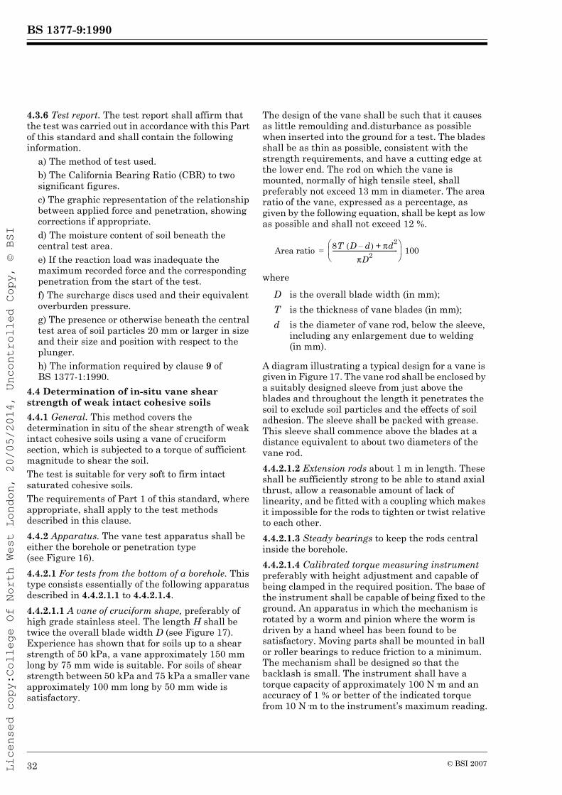
BS 1377-9:1990
Licensed copy:College Of North West London, 20/05/2014, Uncontrolled Copy, © BSI
4.3.6 Test report. The test report shall affirm that the test was carried out in accordance with this Part of this standard and shall contain the following information.
a) The method of test used.b) The California Bearing Ratio (CBR) to two significant figures.c) The graphic representation of the relationship between applied force and penetration, showing corrections if appropriate.d) The moisture content of soil beneath the central test area.e) If the reaction load was inadequate the maximum recorded force and the corresponding penetration from the start of the test.f) The surcharge discs used and their equivalent overburden pressure.g) The presence or otherwise beneath the central test area of soil particles 20 mm or larger in size and their size and position with respect to the plunger.h) The information required by clause 9 of BS 1377-1:1990.
4.4 Determination of in-situ vane shear strength of weak intact cohesive soils4.4.1 General. This method covers the determination in situ of the shear strength of weak intact cohesive soils using a vane of cruciform section, which is subjected to a torque of sufficient magnitude to shear the soil.The test is suitable for very soft to firm intact saturated cohesive soils.The requirements of Part 1 of this standard, where appropriate, shall apply to the test methods described in this clause.4.4.2 Apparatus. The vane test apparatus shall be either the borehole or penetration type (see Figure 16).4.4.2.1 For tests from the bottom of a borehole. This type consists essentially of the following apparatus described in 4.4.2.1.1 to 4.4.2.1.4.4.4.2.1.1 A vane of cruciform shape, preferably of high grade stainless steel. The length H shall be twice the overall blade width D (see Figure 17). Experience has shown that for soils up to a shear strength of 50 kPa, a vane approximately 150 mm long by 75 mm wide is suitable. For soils of shear strength between 50 kPa and 75 kPa a smaller vane approximately 100 mm long by 50 mm wide is satisfactory.
The design of the vane shall be such that it causes as little remoulding and.disturbance as possible when inserted into the ground for a test. The blades shall be as thin as possible, consistent with the strength requirements, and have a cutting edge at the lower end. The rod on which the vane is mounted, normally of high tensile steel, shall preferably not exceed 13 mm in diameter. The area ratio of the vane, expressed as a percentage, as given by the following equation, shall be kept as low as possible and shall not exceed 12 %.
where
A diagram illustrating a typical design for a vane is given in Figure 17. The vane rod shall be enclosed by a suitably designed sleeve from just above the blades and throughout the length it penetrates the soil to exclude soil particles and the effects of soil adhesion. The sleeve shall be packed with grease. This sleeve shall commence above the blades at a distance equivalent to about two diameters of the vane rod.4.4.2.1.2 Extension rods about 1 m in length. These shall be sufficiently strong to be able to stand axial thrust, allow a reasonable amount of lack of linearity, and be fitted with a coupling which makes it impossible for the rods to tighten or twist relative to each other.4.4.2.1.3 Steady bearings to keep the rods central inside the borehole.4.4.2.1.4 Calibrated torque measuring instrument preferably with height adjustment and capable of being clamped in the required position. The base of the instrument shall be capable of being fixed to the ground. An apparatus in which the mechanism is rotated by a worm and pinion where the worm is driven by a hand wheel has been found to be satisfactory. Moving parts shall be mounted in ball or roller bearings to reduce friction to a minimum. The mechanism shall be designed so that the backlash is small. The instrument shall have a torque capacity of approximately 100 N·m and an accuracy of 1 % or better of the indicated torque from 10 N·m to the instrument’s maximum reading.
D is the overall blade width (in mm);T is the thickness of vane blades (in mm);d is the diameter of vane rod, below the sleeve,
including any enlargement due to welding (in mm).
Area ratio 8T D d–( ) πd2+πD2----------------------------------------------
⎝ ⎠⎜ ⎟⎛ ⎞
100=
32 © BSI 2007

BS 1377-9:1990
Licensed copy:College Of North West London, 20/05/2014, Uncontrolled Copy, © BSI
4.4.2.2 For direct penetration from ground surface. This type consists essentially of the following:
a) a vane as specified in 4.4.2.1.1;b) a vane protecting shoe for each size of vane (see Figure 18);c) extension rods as specified in 4.4.2.1.2 (see Figure 16);d) extension tubes about 1 m in length with couplings on the outer face to case the hole;e) a calibrated torque measuring instrument as specified in 4.4.2.1.4.
4.4.3 Pretest check. The apparatus shall be checked for satisfactory operation prior to each usage in the field.4.4.4 Procedure4.4.4.1 For tests at the bottom of a borehole4.4.4.1.1 Lower the vane, together with its extension rods, into the borehole which shall normally be cased for its whole depth. Take care that the rod couplings remain tight while the vane is lowered. Place sufficient bearings to steady the rods laterally throughout the length of the rods. The spacing of the bearings shall depend upon the rigidity of the extension rods, and shall normally be between 3 m and 9 m.4.4.4.1.2 With the vane resting at the bottom of the borehole and with the rods located centrally at the top of the borehole, push the vane steadily without twisting, a distance of not less than three times the diameter of the borehole into the undisturbed soil or at least twice the length of the vane, whichever is the greater.4.4.4.1.3 Place the torque head over the top of the upper extension rod and then adjust it to the required height. Couple the instrument to the extension rods. Fix the base of the torque head firmly to the ground. Set the measuring gauge to zero taking care that any backlash in the torque head has been taken up.4.4.4.1.4 Rotate the torque head until the soil is sheared by the vane. Read the gauge at maximum deflection, thus indicating the torque required to shear the soil.Rotate the torque head throughout the test at a rate within the range 0.10°/s to 0.20°/s (6°/min to 12°/min).
4.4.4.1.5 Remove the torque measuring instrument and withdraw the vane from the ground.4.4.4.2 For direct penetration from ground surface4.4.4.2.1 Lock the vane in place inside the protecting shoe, and jack or drive to the required depth using a light boring rig or tripod. Take care that the rods remain tight while the vane is lowered. Place steady bearings about every 3 m to centralize and reduce friction between the rods and extension pipes.4.4.4.2.2 When the vane and protecting shoe have penetrated to the required depth, push the vane steadily without twisting a distance of at least 0.5 m into the undisturbed soil below the protecting shoe.4.4.4.2.3 Position the torque head as specified in 4.4.4.1.3.4.4.4.2.4 Rotate tile vane as specified in 4.4.4.1.4.4.4.4.2.5 Remove the torque measuring instrument and pull back the vane fully into its protecting shoe, before removing it from the ground.4.4.5 Calculation8). Calculate the vane shear strength of the soil, τf (in kPa), from the equation:
where
Assuming the distribution of the shear strength is uniform across the ends of a cylinder and around the perimeter then:
where
As the ratio of length to width of the vane is 2 to 1 the value of K may be simplified in terms of the diameter so that it becomes:
K = 3.66D3 × 10–6
NOTE It is important that these dimensions are checked periodically to ensure the vane is not distorted or worn.
8) See form 9(g) of Appendix A.
M is the torque to shear the soil (in N·m);K is a constant depending on dimensions and
shape of the vane.
D is the measured width of vane (in mm);H is the measured height of vane (in mm).
τfMK-----=
K πD2H2
------------ 1 D3H--------+⎝ ⎠
⎛ ⎞ 10 6–=
© BSI 2007 33

BS 1377-9:1990
Licensed copy:College Of North West London, 20/05/2014, Uncontrolled Copy, © BSI
4.4.6 Test report. The test report shall affirm that the test was carried out in accordance with this Part of this standard and shall contain the following information.
a) The method of test used.b) The vane shear strength (in kPa) to two significant figures.c) The type of vane test apparatus.d) The method of calculating the result when different from that specified in 4.4.5.e) The information required by clause 9 of BS 1377-1:1990.
5 In-situ corrosivity tests5.0 IntroductionThis clause of the standard describes two methods for determining in-situ the likelihood of underground corrosion of buried metal structures.The results of these tests should be interpreted by a specialist.5.1 Determination in-situ of the apparent resistivity of soil5.1.1 General. This method covers the determination of the electrical resistivity of soil tested in situ for a selected depth or a range of depths. (See note 1.)The test is used to assess the corrosivity of the soil towards various metals. Resistivity is the electrical resistance of an element of unit cross-sectional area and unit length. Its value indicates the relative capability of the soil to carry electric currents. Generally the severity of corrosion decreases as the apparent resistivity rises.The method consists of passing a current (see note 2) into the ground between two electrodes (A, B) and measuring the consequent apparent resistivity between another two electrodes (C, D) situated at equi-distant spacings (AC, CD and DB) and collinear between electrodes A and B. This arrangement corresponds to the conventional “Wenner”, equally spaced, four electrode configuration. Two separate measurements of the resistivity are made for a test at each selected depth with the electrodes set at approximately right angles for the two measurements. When testing in borrow areas one measurement may be made with the electrodes in the same line as the direction of the test locations and another with the electrodes set at approximately right angles to the line of tests.Resistivity may also be measured in the laboratory (see clause 10 of BS 1377-3:1990).
NOTE 1 The resistivity measurement represents the average resistivity of a hemisphere of soil of a radius more or less equal to the spacing between adjacent electrodes as used in the test. The selected depth of a test is therefore more or less equal to the spacing of adjacent electrodes and bears no relation to the embedment depth of the electrodes. The selected depth of a test is commonly taken as equal to the proposed depth of the buried metal inclusion, e.g. a pipeline. NOTE 2 The test method specified is based on the use of alternating current. Direct current measurements are also made in resistivity tests but these are generally more concerned with geological investigations. The use of direct current can cause polarization effects and can thus lead to an uncharacteristically high resistance being measured. For this reason direct current measurements are not permissible in this type of test.NOTE 3 The measurements are rendered unreliable if beneath the test location electrical conductors are present such as metal pipes, cables or other conducting objects, also if the soil formation contains highly conductive materials such as ferruginous soil which is not typical of the formation.The requirements of Part 1 of this standard, where appropriate, shall apply to the test methods described in this clause.5.1.2 Apparatus5.1.2.1 Calibrated earth impedance ohmmeter, suitable for measurements by Wenner equally spaced, four-electrode configuration. The ohmmeter shall have a performance complying with class 2.5 of BS 89 and shall produce an internally generated attenuating current supply of frequency between 100 Hz and 150 Hz provided either by a rotating generator or by an oscillator with a direct current supply. The total measuring range shall be at least 0 Ω to 1 900 Ω with a readability to at least three significant figures. The instrument shall be recalibrated at intervals not exceeding 2 yrs.A copy of the manufacturer’s operating instructions shall be available at all times when in use.5.1.2.2 Electrodes. Set of four metal rods, each typically about 500 mm long and about 10 mm to 20 mm nominal diameter, with one end pointed for driving into the soil. The electrodes shall be formed with a handle and have a low electrical resistance contact point for wire connection. The rod material shall be a good electrical conductor and the surface shall be clean and uncorroded. Suitable material for the rods is stainless steel, brass or copper-plated steel rods.5.1.2.3 Insulated wire cable. Set of four reels of robust insulated stranded copper wire suitable for use with earth resistance meter, and each of sufficient length depending upon the maximum anticipated spacing of the electrodes. Cable complying with BS 6231, type BK PVC-insulated flexible cable, 1.5 mm2 nominal cross-sectional area of conductor has been found to be suitable. Each reel of wire shall have fitted at one end a robust clamp to ensure low electrical resistance contact with the electrode, and at the other a suitable terminal to fit the ohmmeter.
34 © BSI 2007

BS 1377-9:1990
Licensed copy:College Of North West London, 20/05/2014, Uncontrolled Copy, © BSI
5.1.2.4 Installation equipment, such as a 1 kg hammer for inserting the electrodes into the soil.5.1.2.5 Linear measuring equipment for setting out, such as a measuring tape.5.1.3 Procedure. Tests shall not be made when the soil is frozen or flooded. At the site of each resistivity test proceed as follows working at the ground surface or the base of an excavation.NOTE Safety precautions should be taken in accordance with the manufacturer’s instructions when using the ohmmeter, particularly if working near high-tension systems. In this case rubber gloves should be worn and the operator should stand on a rubber mat or wear rubber shoes.5.1.3.1 Select the test location, the length of which shall be three times the selected test depth, where the soil conditions are anticipated to be uniform and away from large non-conductive bodies such as boulders or concrete foundations.NOTE Highly conductive bodies, such as existing metal pipes and electric cables should not be within about one half the selected depth of the test unless they are at right angles to the line of the electrodes.5.1.3.2 Install the two electrodes for transmitting the a.c. current, A and B, so that they are spaced apart a distance equal to three times the selected test depth, and such that each electrode penetrates into the soil at the ground surface for a depth of at least 150 mm and over this length is in full contact with the soil. The maximum penetration of the electrodes beyond the minimum of 150 mm shall not exceed one-twentieth of the selected test depth. The minimum spacing between these electrodes A and B shall be 3 m.NOTE Where topsoil is present at the test location the electrodes should be driven through it to penetrate into the subsoil.5.1.3.3 Install the other two electrodes, C and D, directly between and in line with electrodes A and B, such that all three spacings between the four electrodes are equi-distant. The specifications for the penetration and contact of these electrodes shall be the same as for electrodes A and B.NOTE When the soil around the electrodes is relatively dry such that there is poor conductivity between the electrode and the soil, it is permissible to wet the soil in the vicinity of the electrodes.5.1.3.4 Connect the appropriate terminals on the ohmmeter to the four electrodes with the insulated wire cable.5.1.3.5 Apply a stable a.c. current to electrodes A and B, operating the ohmmeter in accordance with the manufacturer’s instructions, which may require the test current level to be adjusted before taking the measurements.5.1.3.6 Record the measurement of the soil resistance between electrodes C and D when the instrument reading becomes stable. Record values to two significant figures.
5.1.3.7 Remove the electrodes and repeat the procedure specified above, firstly for other selected depths if required at the same test location, and secondly such that the line of the electrodes is approximately at right angles to the line of the first measurement or series of measurements. If the two measurements at a selected depth differ by more than 15 % of the mean value they shall be repeated.5.1.4 Calculation and expression of the results. Calculate the apparent resistivity, rs [in Ω·m (see note)], for each measurement at the test location from the equation:
rs = 2 (π a R)where
The value of the apparent resistivity shall be reported to two significant figures.NOTE This is to conform with SI units. The customary unit, ohm·cm, is equal to 0.01 Ω·m.5.1.5 Test report. The test report shall affirm that the test was carried out in accordance with this Part of this standard and shall contain the following information.
a) The method of test used.b) The mean value of the apparent resistivity (in Ω·m) to two significant figures.c) The two individual values of apparent resistivity and their directions when more than 15 % different to their mean value.d) The distance between adjacent electrodes in metres, and the selected test depth. If the spacing difference is not equal to three times the test depth, the reason for that difference.e) The information required by clause 9 of BS 1377-1:1990.
5.2 Determination in-situ of the redox potential of soil5.2.1 General. This method covers the determination of the redox potential (reduction/oxidation) of soil tested in situ at a selected depth by measuring the electro-chemical potential between a platinum electrode and a saturated calomel reference electrode. The test is used to indicate the likelihood of microbial corrosion of metals by sulphate-reducing bacteria which can proliferate in anaerobic conditions.The redox potential is principally related to the oxygen in the soil, and a high value indicates that a relatively large amount is present. Anaerobic microbial corrosion can occur if a soil has a low oxygen content and hence a low redox potential.
a is spacing between adjacent electrodes (in m);R is measured resistance (in Ω).
© BSI 2007 35
BS 1377-9:1990
Licensed copy:College Of North West London, 20/05/2014, Uncontrolled Copy, © BSI
This standard requires the use of a calomel reference probe as defined in 5.2.2.2, in order to be consistent with the laboratory test method (see clause 11 of BS 1377-3:1990). This is not intended to prohibit the use of the other established portable versions of reference probes, e.g. copper/copper sulphate and silver/silver chloride (see note). In submitting reports the type of reference probe used and the correction factor applied to convert the measurement to the standard hydrogen electrode shall be given.Redox potential may also be measured in the laboratory (see clause 11 of BS 1377-3:1990).NOTE Where the other types of reference probes, e.g. copper/copper sulphate and silver/silver chloride, are used it is very important to note that their preparation and storage procedures are different from that required for calomel probes and the manufacturer’s instructions should be followed. Moreover copper/copper sulphate probes are not suitable in chloride contaminated soil or in alkaline environments when silver/silver chloride should be used. Copper/copper sulphate cells are also sensitive to heat, light and a wide variety of chemicals.The correction factors for reference probes to convert the measurement to the standard hydrogen electrode are as follows:
The requirements of Part 1 of this standard, where appropriate, shall apply to the test methods described in this clause.5.2.2 Apparatus5.2.2.1 Platinum probe of a design having two separate platinum electrodes embedded in the nose piece. Also a means of protection when not in use. The probe shall have a connecting lead permitting the inclusion of each platinum electrode individually in an electrical circuit. Each connection shall be separately identified.
5.2.2.2 Calomel reference probe, having a mercury/mercuric chloride reference electrode which can be refilled and with a connection to a porous ceramic junction. The calomel reference electrode shall be kept clean when not in use by being stored in a sealed container. The precipitation of crystals shall be prevented when not in use, particularly at the porous junction, by storing upright and closing the breather hole.NOTE The platinum and calomel probes are often separate and the latter made of glass which can make field use sometimes difficult. The National Corrosion Service at the National Physical Laboratory (NPL)9) has designed and supplies a robust redox probe that combines both the pair of platinum electrodes and a calomel reference probe mounted together behind a steel-tipped nose cone that is fitted on the end of a steel tube which can be driven into fine- and medium-grained soils. The NPL redox probe is supplied complete with ancillary equipment for cleaning the electrodes.5.2.2.3 Calibrated millivoltmeter, having a performance complying with class 1.5 of BS 89. The total measuring range shall be at least 0 V d.c. to 2 V d.c. with a readability at least to 10 mV. The input impedance shall be not less than 106 Ω and the polarity (positive or negative) shall be marked on the two input terminals.The instrument shall include suitable insulated flexible electric cable and connectors for use with the probes.The instrument shall be recalibrated at intervals not exceeding 2 yrs.5.2.2.4 Installation equipment consisting of a soil auger, spade and trowel to excavate soil to test level, and, where soil is compact, a 1 kg hammer and spike.5.2.2.5 pH measuring apparatus as specified and calibrated in accordance with clause 9 of BS 1377-3:1990.5.2.2.6 Disturbed sample container of glass or dense plastic, that can be hermetically sealed.NOTE When a sample from the test location is required for microbiological examination, a glass container of a size suitable to hold about 500 mL will need to have been cleaned and sterilized by scalding with boiling water beforehand. Alternatively medically sterilized plastic bags may be used. Fill the container completely and minimize air voids.
5.2.3 Materials5.2.3.1 Saturated solution of potassium chloride in a screw-topped plastic bottle either with pouring lip suitable for filling the reservoir of the calomel reference probe or a separate small dropper or syringe. 500 mL is a suitable quantity.
Mercury/mercuric chloride
240a mV
at 25 °C
Copper/copper sulphate 316 mVSilver/silver chloride
246 mVb
a The factor of 240 is normally rounded to 250 for the purposes of this test.b In 3 % sodium chloride solution.
⎭⎪⎪⎪⎪⎬⎪⎪⎪⎪⎫
9) National Physical Laboratory, Teddington, Middlesex TW11 0LW.
36 © BSI 2007

BS 1377-9:1990
Licensed copy:College Of North West London, 20/05/2014, Uncontrolled Copy, © BSI
5.2.3.2 Jeweller’s rouge.5.2.3.3 Colourless methylated spirits, 70 % by volume with 30 % by volume distilled water, in a screw-topped wide-mouth bottle. 500 mL is a suitable quantity.5.2.3.4 Distilled water. Two differently marked wash bottles full for cleaning platinum electrodes. 500 mL is a suitable quantity for each bottle.5.2.3.5 Paper tissues and absorbent-type surgical cotton wool swabs.5.2.4 ProcedureNOTE Thorough cleanliness of the probes is essential for reliable results.5.2.4.1 Assemble from the storage unit according to the manufacturer’s operating instructions the calomel reference probe, ensuring that the unit is full of a saturated solution of potassium chloride and that this moistens the porous junction. Remove any air bubbles in the potassium chloride solution by gently tapping the probe and remove excess fluid from the porous junction.NOTE 1 During use on site it is important to prevent precipitation of crystals at the porous junction. This may be done by keeping the probe between tests in distilled water in a wide-necked bottle with a rubber bung to ensure that the porous junction is kept moist.Clean and polish each platinum electrode. Initially smear the surfaces lightly with moist jeweller’s rouge and use gentle abrasive action with cotton wool swabs. Follow with a single wash using the methylated spirits. Afterwards wash thoroughly with distilled water. Lastly dry each electrode with clean paper tissues.NOTE 2 Where the platinum electrode is dipped into distilled water for washing, the bottles will need separate identification to select the correct sequence when reused.5.2.4.2 Connect the positive terminal of the millivoltmeter with the electric cable to one of the platinum electrodes and the negative terminal to the calomel reference electrode, but leave the circuit open. This circuit shall be considered to give positive readings.5.2.4.3 Tests shall always be made below the level of organic growth. A hole not less than 150 mm in diameter is needed to reach the selected level when using separate probes. A combined redox probe may be driven from the surface to the selected level in weak soil, otherwise it may be necessary to auger or dig a hole part way.
5.2.4.4 If the probes are separate install them about 100 mm apart in the hole. The platinum probe shall penetrate at least 100 mm to ensure full soil contact below any disturbed surface material. A combined redox probe shall be pressed into position sufficiently to obtain full soil contact on the electrodes.5.2.4.5 Rotate the platinum probe about a quarter turn without letting air reach the probe. Close the electric circuit then take the reading as soon as the voltage becomes stable. It may be necessary to wait 30 s or more for stable conditions to be reached. Where the probes are separate turn the platinum probe one revolution under firm hand pressure to ensure good contact. Rotate the combined redox probe a half to one revolution.Record the reading to the nearest 10 mV when the voltage is steady and record whether it is positive or negative.NOTE Very occasionally the current between the platinum electrode and the reference electrode will be in the reverse direction such as to require the connections to the millivoltmeter to be reversed. In this case the reading should be considered to be negative.5.2.4.6 Transfer the electric circuit to the other platinum electrode, connecting it again to the positive terminal of the millivoltmeter, and repeat the procedure as specified in 5.2.4.5. Record the reading to the nearest 10 mV and its polarity.5.2.4.7 If the two readings differ by more than 20 mV remove the probes, reclean the platinum electrodes and re-install in a different position at the test site. Do not install the probes in the original position because oxygen will have penetrated and a false reading could result. Repeat the procedures as specified in 5.2.4.5 and 5.2.4.6.5.2.4.8 Remove the probes and clean the electrodes taking note of the requirements of 5.2.2.2 and 5.2.4.1.5.2.4.9 Place a disturbed sample from the position of the test in an hermetically sealed container.5.2.4.10 Determine the pH of the sample by the method specified in clause 9 of BS 1377-3:1990.
© BSI 2007 37

BS 1377-9:1990
Licensed copy:College Of North West London, 20/05/2014, Uncontrolled Copy, © BSI
5.2.5 Calculations and expression of the results. The mean of the two acceptable readings and their sign shall be recorded as the potential of the platinum probe, Ep, to the nearest 10 mV. Calculate the redox potential, Eh (in mV), to the nearest 10 mV from the equation:
Eh = Ep + 250 + 60 (pH – 7)where
5.2.6 Test report. The test report shall affirm that the test was carried out in accordance with this Part of this standard and shall contain the following information.
a) The method of test used.b) The mean value of the potential (in mV) of the two platinum probes to the nearest 10 mV.c) The redox potential (in mV) to the nearest 10 mV.d) The pH value.e) The type of reference probe used in the test.f) The information required by clause 9 of BS 1377-1:1990.
Ep is the potential of the platinum probe (in mV) (may be a positive or negative value);
pH is the value of the acidity of an aqueous solution of the soil at the test position as determined by the method specified in clause 9 of BS 1377-3:1990;
250 is the correction factor for a calomel reference probe to convert the measurement to the standard hydrogen electrode.
38 © BSI 2007

BS 1377-9:1990
Licensed copy:College Of North West London, 20/05/2014, Uncontrolled Copy, © BSI
Figure 1 — Small pouring cylinder for the determination of the density of fine-and medium-grained soils
© BSI 2007 39

BS 1377-9:1990
Licensed copy:College Of North West London, 20/05/2014, Uncontrolled Copy, © BSI
Figure 2 — Scraper for levelling surface of soil
40 © BSI 2007

BS 1377-9:1990
Licensed copy:College Of North West London, 20/05/2014, Uncontrolled Copy, © BSI
Figure 3 — Calibrating container for use with the small pouring cylinder
© BSI 2007 41
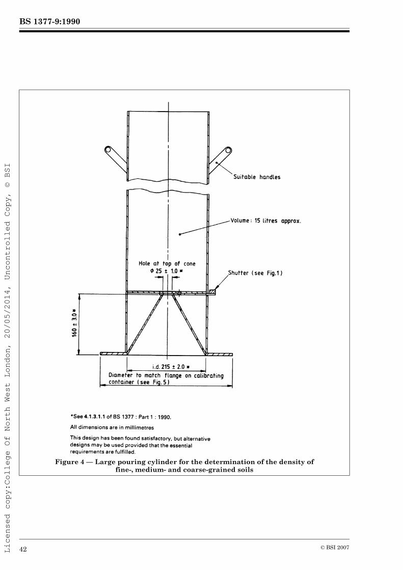
BS 1377-9:1990
Licensed copy:College Of North West London, 20/05/2014, Uncontrolled Copy, © BSI
Figure 4 — Large pouring cylinder for the determination of the density of fine-, medium- and coarse-grained soils
42 © BSI 2007

BS 1377-9:1990
Licensed copy:College Of North West London, 20/05/2014, Uncontrolled Copy, © BSI
Figure 5 — Calibrating container for use with large pouring cylinder
© BSI 2007 43

BS 1377-9:1990
Licensed copy:College Of North West London, 20/05/2014, Uncontrolled Copy, © BSI
Figure 6 — Core cutter apparatus for soil density determination
44 © BSI 2007

BS 1377-9:1990
© B
SI 200745
es
Licensed copy:College Of North West London, 20/05/2014, Uncontrolled Copy, © BSI
Figure 7 — Modes of operation of nuclear surface density and moisture gaug

BS 1377-9:1990
Licensed copy:College Of North West London, 20/05/2014, Uncontrolled Copy, © BSI
Figure 8 — Examples of penetrometer tips with and without a friction sleeve
46 © BSI 2007

BS 1377-9:1990
Licensed copy:College Of North West London, 20/05/2014, Uncontrolled Copy, © BSI
Figure 9 — Permitted tolerances, including allowances for wear, surface finish and typical manufacturing dimensions for the standard cone for the cone penetration test
© BSI 2007 47

BS 1377-9:1990
Licensed copy:College Of North West London, 20/05/2014, Uncontrolled Copy, © BSI
Figure 10 — Permitted tolerances, including allowances for wear, surface finish and typical manufacturing dimensions for the standard friction sleeve for the cone penetration test
Figure 11 — Alternative forms of 90 cone for dynamic probing (for dimensions see Table 1)
48 © BSI 2007

BS 1377-9:1990
© B
SI 200749
Licensed copy:College Of North West London, 20/05/2014, Uncontrolled Copy, © BSI
Figure 12 — Split-barrel sampler assembly
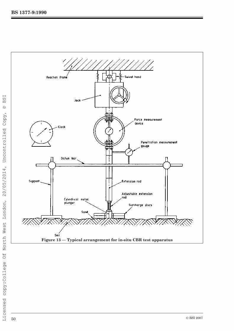
BS 1377-9:1990
Licensed copy:College Of North West London, 20/05/2014, Uncontrolled Copy, © BSI
Figure 13 — Typical arrangement for in-situ CBR test apparatus
50 © BSI 2007

BS 1377-9:1990
Licensed copy:College Of North West London, 20/05/2014, Uncontrolled Copy, © BSI
Figure 14 — Typical CBR test results curves
© BSI 2007 51

BS 1377-9:1990
Licensed copy:College Of North West London, 20/05/2014, Uncontrolled Copy, © BSI
Figure 15 — Force-penetration curves for a CBR value of 100 % and other CBR values
52 © BSI 2007

BS 1377-9:1990
Licensed copy:College Of North West London, 20/05/2014, Uncontrolled Copy, © BSI
Figure 16 — Typical arrangements for in-situ vane test apparatus
© BSI 2007 53

BS 1377-9:1990
Licensed copy:College Of North West London, 20/05/2014, Uncontrolled Copy, © BSI
Figure 17 — Typical borehole vane and rod mounting
Figure 18 — Typical vane protecting shoe
54 © BSI 2007

BS 1377-9:1990
Licensed copy:College Of North West London, 20/05/2014, Uncontrolled Copy, © BSI
Appendix A Typical test data and calculation formsThe following test sheets are given as examples; other suitable forms may be used.
Form Title
9 (a) In-situ density testSand replacement methods
9 (b) In-situ density testWater replacement method
9 (c) In-situ density test Core cutter method
9 (d) Cone penetration test9 (e) Dynamic probing test9 (f) In-situ CBR test9 (g) In-situ vane shear strength test
© BSI 2007 55
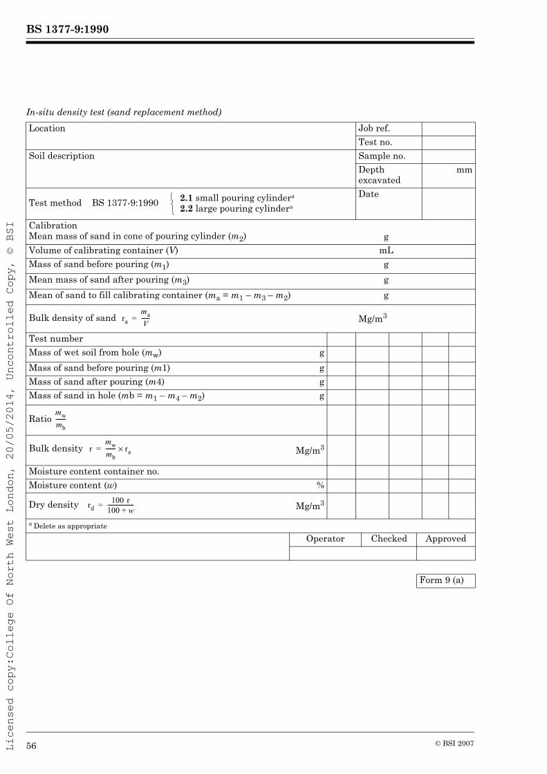
BS 1377-9:1990
Licensed copy:College Of North West London, 20/05/2014, Uncontrolled Copy, © BSI
In-situ density test (sand replacement method)Location Job ref.
Test no.Soil description Sample no.
Depth excavated
mm
Test method BS 1377-9:1990 2.1 small pouring cylindera
2.2 large pouring cylindera
Date
CalibrationMean mass of sand in cone of pouring cylinder (m2) gVolume of calibrating container (V) mLMass of sand before pouring (m1) gMean mass of sand after pouring (m3) gMean of sand to fill calibrating container (ma = m1 – m3 – m2) g
Bulk density of sand Mg/m3
Test numberMass of wet soil from hole (mw) gMass of sand before pouring (m1) gMass of sand after pouring (m4) gMass of sand in hole (mb = m1 – m4 – m2) g
Ratio
Bulk density Mg/m3
Moisture content container no.Moisture content (w) %
Dry density Mg/m3
a Delete as appropriate
Operator Checked Approved
Form 9 (a)
⎩⎨⎧
ramaV------=
mwmb-------
rmwmb------- ra×=
rd100 r
100 w+-------------------=
56 © BSI 2007
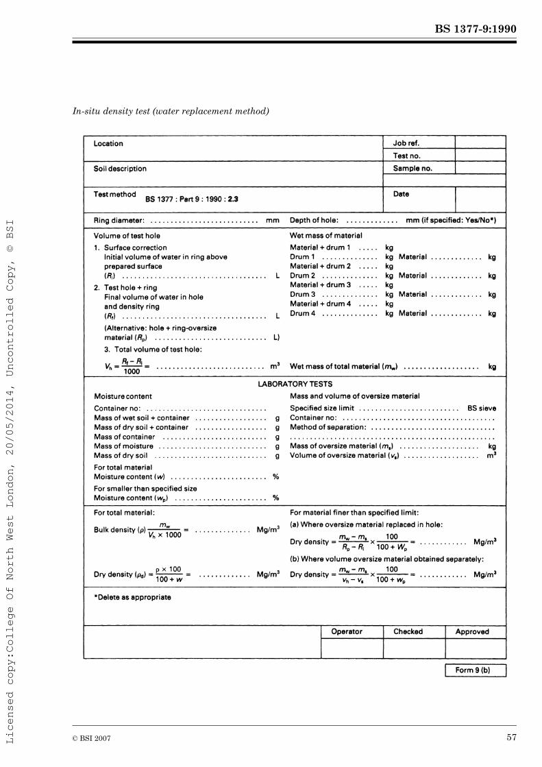
BS 1377-9:1990
Licensed copy:College Of North West London, 20/05/2014, Uncontrolled Copy, © BSI
In-situ density test (water replacement method)
© BSI 2007 57

BS 1377-9:1990
Licensed copy:College Of North West London, 20/05/2014, Uncontrolled Copy, © BSI
In situ density test (core cutter method)Location Job ref.
Soil description and applicable test numbers. Sample no.
Test method DateBS 1377-9:1990: 2.4
Length of core cutter: . . . . . . . . . . . . . . . . . . . mmVolume of core cutter (Vc) . . . . . . . . . cm3
Test numberMass of core cutter and wet soil (ms) gMass of core cutter (mc) g
Mass of west soil (ms – mc) g
Bulk density Mg/m3
Moisture content container no.Moisture content (w) %
Dry density Mg/m3
Operator Checked Approved
Form 9 (c)
rms mc–Vc
-------------------=
rd100 r
100 w+-------------------=
58 © BSI 2007

BS 1377-9:1990
Licensed copy:College Of North West London, 20/05/2014, Uncontrolled Copy, © BSI
Static cone penetration test
© BSI 2007 59

BS 1377-9:1990
Licensed copy:College Of North West London, 20/05/2014, Uncontrolled Copy, © BSI
Dynamic probing test
60 © BSI 2007

BS 1377-9:1990
Licensed copy:College Of North West London, 20/05/2014, Uncontrolled Copy, © BSI
In-situ CBR test
© BSI 2007 61

BS 1377-9:1990
Licensed copy:College Of North West London, 20/05/2014, Uncontrolled Copy, © BSI
In-situ vane shear strength testLocation Job ref.
Borehole/Test no.a
Sheet no.Test method Ground level: Weather:
BS 1377-9:1990: 4.4 (Ordnance datum)
m
Vane dimensions: height
mm; Dia. mm Instrument no. ................... Date
Vane constant, K: mm3 × 10–6 Depth to ground water level:
Test record Rate of loading ............... radians/min or degree/min.a
Depth of borehole below ground level
Depth of vane tip
Max. force applied and time to failure
Value of frictional force
Torque, M Shear strength M/K
Remarks (soil description at test levels, etc.)
m m N min s. N N·m kPa
a Delete as appropriate
Operator Checked Approved
Form 9 (g)
62 © BSI 2007

BS 1377-9:1990
Licensed copy:College Of North West London, 20/05/2014, Uncontrolled Copy, © BSI
Publications referred to
BS 89, Specification for direct acting indicating electrical measuring instruments and their accessories. BS 1377, Methods of test for soils for civil engineering purposes. BS 1377-1, General requirements and sample preparation. BS 1377-2, Classification tests. BS 1377-3, Chemical and electro-chemical tests. BS 1610, Materials testing machines and force verification equipment. BS 4019, Specification for rotary core drilling equipment. BS 4019-1, Basic equipment. BS 5573, Code of practice for safety precautions in the construction of large diameter boreholes for piling and other purposes. BS 5930, Code of practice for site investigations10). BS 6231, Specification for PVC-insulated cables for switchgear and controlgear wiring. BS EN ISO 22476-2, Geotechnical investigation and testing — Field testing — Part 1: Dynamic probing.BS EN ISO 22476-3, Geotechnical investigation and testing — Field testing — Part 2: Standard penetration test.ASTM D2922 American Society for Testing and Materials. Standard test methods for density of soil and soil aggregate in place by nuclear methods (shallow depth).ASTM D3017 American Society for Testing and Materials. Standard test methods for moisture content of soil and soil-aggregate in place by nuclear methods (shallow depth).
10) Referred to in the foreword only.
© BSI 2007

Licensed copy:College Of North West London, 20/05/2014, Uncontrolled Copy, © BSI
BS 1377-9: 1990
BSI389 Chiswick High RoadLondonW4 4AL
BSI — British Standards InstitutionBSI is the independent national body responsible for preparing British Standards. It presents the UK view on standards in Europe and at the international level. It is incorporated by Royal Charter.
RevisionsBritish Standards are updated by amendment or revision. Users of British Standards should make sure that they possess the latest amendments or editions.It is the constant aim of BSI to improve the quality of our products and services. We would be grateful if anyone finding an inaccuracy or ambiguity while using this British Standard would inform the Secretary of the technical committee responsible, the identity of which can be found on the inside front cover. Tel: +44 (0)20 8996 9000. Fax: +44 (0)20 8996 7400.BSI offers members an individual updating service called PLUS which ensures that subscribers automatically receive the latest editions of standards.
Buying standardsOrders for all BSI, international and foreign standards publications should be addressed to Customer Services. Tel: +44 (0)20 8996 9001. Fax: +44 (0)20 8996 7001. Email: [email protected]. Standards are also available from the BSI website at http://www.bsi-global.com.In response to orders for international standards, it is BSI policy to supply the BSI implementation of those that have been published as British Standards, unless otherwise requested.
Information on standardsBSI provides a wide range of information on national, European and international standards through its Library and its Technical Help to Exporters Service. Various BSI electronic information services are also available which give details on all its products and services. Contact the Information Centre. Tel: +44 (0)20 8996 7111. Fax: +44 (0)20 8996 7048. Email: [email protected] members of BSI are kept up to date with standards developments and receive substantial discounts on the purchase price of standards. For details of these and other benefits contact Membership Administration. Tel: +44 (0)20 8996 7002. Fax: +44 (0)20 8996 7001. Email: [email protected] regarding online access to British Standards via British Standards Online can be found at http://www.bsi-global.com/bsonline.Further information about BSI is available on the BSI website at http://www.bsi-global.com.
CopyrightCopyright subsists in all BSI publications. BSI also holds the copyright, in the UK, of the publications of the international standardization bodies. Except as permitted under the Copyright, Designs and Patents Act 1988 no extract may be reproduced, stored in a retrieval system or transmitted in any form or by any means – electronic, photocopying, recording or otherwise – without prior written permission from BSI.This does not preclude the free use, in the course of implementing the standard, of necessary details such as symbols, and size, type or grade designations. If these details are to be used for any other purpose than implementation then the prior written permission of BSI must be obtained.
Details and advice can be obtained from the Copyright & Licensing Manager. Tel: +44 (0)20 8996 7070. Fax: +44 (0)20 8996 7553. Email: [email protected].