Soil Structure Interaction Method Comparison -...
50
Integrated Solver Optimized for the next generation 64-bit platform Finite Element Solutions for Geotechnical Engineering Soil Structure Interaction Method Comparison Angel Francisco Martinez Application Engineer MIDAS IT Estados Unidos
-
Upload
truongthuan -
Category
Documents
-
view
237 -
download
4
Transcript of Soil Structure Interaction Method Comparison -...

Integrated Solver Optimized for the next generation 64-bit platform
Finite Element Solutions for Geotechnical Engineering
Soil Structure Interaction Method
Comparison
Angel Francisco MartinezApplication EngineerMIDAS ITEstados Unidos

Integrated Solver Optimized for the next generation 64-bit platform
Finite Element Solutions for Geotechnical Engineering
Contents
1. Introduction
2. Soil Structure Interaction Substructure Method
3. Ground Response Analysis for Calibration
4. Soil Structure Interaction Direct Method
5. Results Comparison Between SSI Methods

GTS NX
3
Soil Structure Interaction
SSI: The phenomenon in which the response of soil and movement of the structure influence each
other. When external forces, such as earthquakes, act on these systems, neither structural
displacements nor ground displacements are independent of each other. Unlike an above-ground
structure, the response of an underground structure subjected to an earthquake is mainly controlled
by the ground displacement. The ground displacement in turn is largely influenced by the dynamic
properties of the ground and its modeling method. The ground exhibits a complete nonlinear
behavior depending on the strains developed in the ground due to the dynamic load. It is therefore
important to closely examine the nonlinearity of the ground relative to strains.

GTS NX
4
Substructure Method Direct Method
Dynamic SSI

Integrated Solver Optimized for the next generation 64-bit platform
Finite Element Solutions for Geotechnical Engineering
Soil Structure Interaction
by Substructure Method

GTS NX
6
Initial Gen model dimensions
Initial pile size is large to show optimal design difference
1. Open Strat file Gen model:• 13 stories: 48 m tall building• 9 piles: -10 m deep, 0.5m diameter• 9m X 9mX 0.5m thick slab
Start FILE midas Gen
1

GTS NX
7
Kh = 0.56 (500,000) / 0.5 = 560,000 Kn/m^3
Add Soil Springs Supports in Gen
1. Right click fixed Boundaries in Tree Menu and Delete
2. Add PY soil springs supports to Gen piles and raft.
Apply Soil Springs in Gen
2
1

GTS NX
8
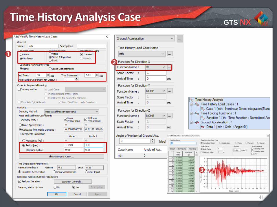
Time History Analysis Case
3
1
2

GTS NX
9
Results for TH in Gen using PY springs
• Check TH Max case for moments YMax : 85 kN/m
• Check TH Max case for axial forcesMax: 1269 kN
• Check TH Max load case for displacementsMax 1.12 mm

Integrated Solver Optimized for the next generation 64-bit platform
Finite Element Solutions for Geotechnical Engineering
Soil Structure Interaction
by Direct Method

GTS NX
11
GTS NX
Linear Equivalent
Time History
Response Spectrum
Eigen Value
Dynamic Analysis
• Free Field
• Linear (Direct)
• Linear (Modal)
• Non linear (Direct)
• Non linear + SRM
• Liquefaction
• Moving Load
• 2D Linear Equivalent

Integrated Solver Optimized for the next generation 64-bit platform
Finite Element Solutions for Geotechnical Engineering
1D Free Field Analysis

GTS NX
13
Define 1D FFA Soil Layers
GTS NX
14
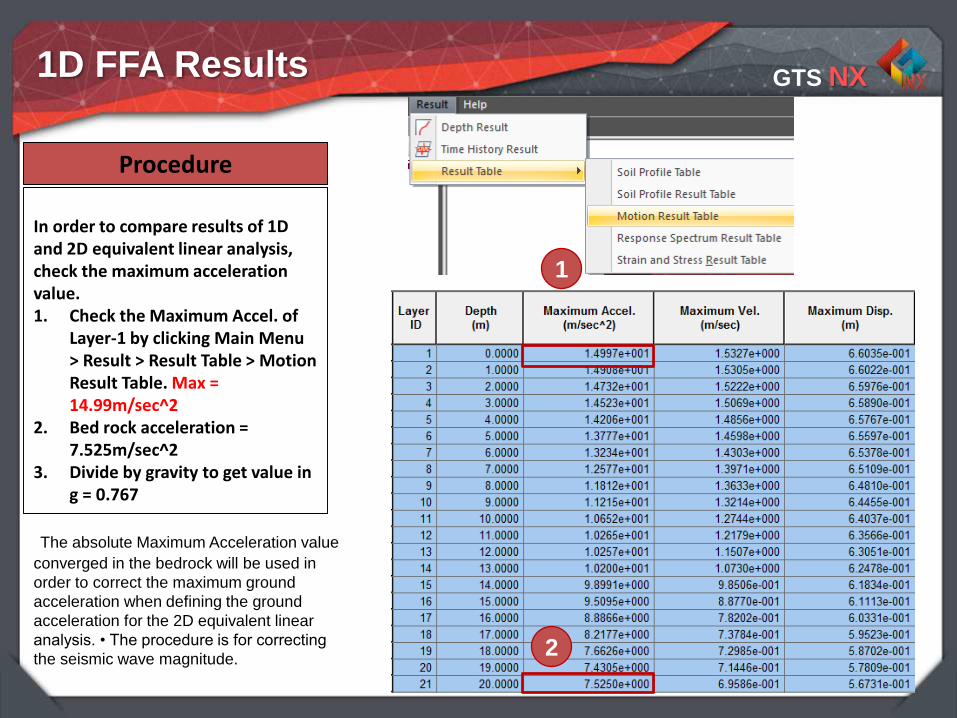
In order to compare results of 1D and 2D equivalent linear analysis, check the maximum acceleration value. 1. Check the Maximum Accel. of
Layer-1 by clicking Main Menu > Result > Result Table > Motion Result Table. Max = 14.99m/sec^2
2. Bed rock acceleration = 7.525m/sec^2
3. Divide by gravity to get value in g = 0.767
Procedure
The absolute Maximum Acceleration value
converged in the bedrock will be used in
order to correct the maximum ground
acceleration when defining the ground
acceleration for the 2D equivalent linear
analysis. • The procedure is for correcting
the seismic wave magnitude.
1D FFA Results
1
2

GTS NX
15
1. Result > Depth Result2. Acceleration results
Procedure1
2
1D ground response analysis cannot readily check a structure, which exists in ground. In such a case, 2D equivalent
linear analysis can be used to check ground – structure interaction.
1D FFA Results

Integrated Solver Optimized for the next generation 64-bit platform
Finite Element Solutions for Geotechnical Engineering
2D Linear Equivalent Analysis

GTS NX
17
The use of quadrilateral elements or map-mesh is recommended
since shear forces will occur between elements while seismic wave
will be applied at ground
Mesh 2D Linear EQ Model (Ground Only)
GTS NX
18
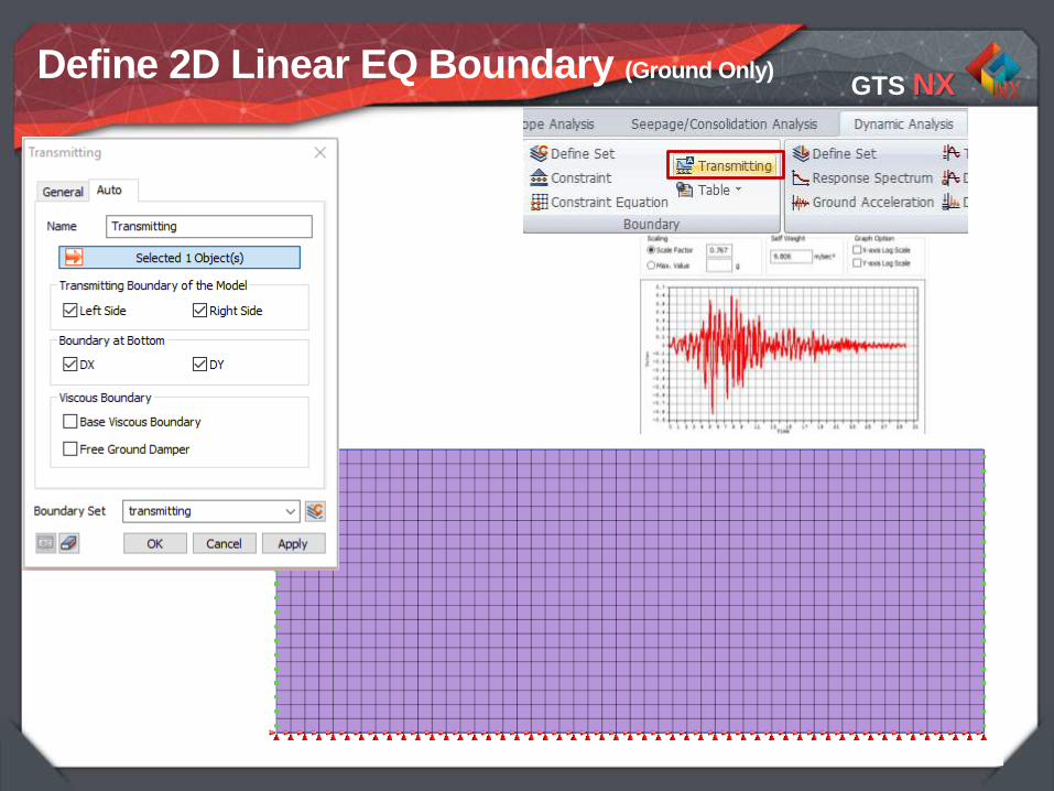
Define 2D Linear EQ Boundary (Ground Only)

GTS NX
19
1. Compare with results related ABS for 2D linear equivalent analysis since results of 1D linear equivalent analysis are absolute.
2. Post Works Tree > EQ. LINEAR - ABS MAX > relative acceleration > Total rel.Max = 14.89m/sec^2
Procedure
2
2D Linear EQ Results (Ground Only)

GTS NX
20
Compare results between 1D and 2D (Ground Only)
Results match between 1D FFA and 2D
Linear EQ. models within 5% at
14.9m/sec^2 acceleration at surface.

GTS NX
21
Find the Max Shear Strain value and at the surface.
Max value = 0.0124
2D Linear EQ Results (Ground Only)

GTS NX
22
Shear Strain G/G0 New G D
0.01 0.3257 34,459 0.1012
0.0124 0.31025 32,824 0.1035
0.02 0.2639 27920 0.1104
Shear Strains from Dynamic curve (Ground Only)
Make table of Max shear strains bands and used the dynamic curve to get new values for
G and D
Initial Shear Modulus (G0) = 105800
Shear Modulus Reduction Factor (G/G0) = 0.31025
New Shear Modulus (G) is = 105800 * 0.3257 = 32,824

Integrated Solver Optimized for the next generation 64-bit platform
Finite Element Solutions for Geotechnical Engineering
3D Time History Analysis

GTS NX
24
Use same dynamic curve and time
history function
Dynamic SSI
Free Field 1D
Linear Equivalent 2D
Time History 3D
GTS NX
25
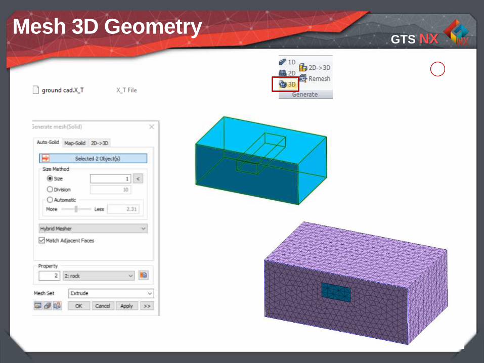
Mesh 3D Geometry

GTS NX
26
2
3D LTH Loads and Boundaries (ground only)
1 45
6
3

GTS NX
27
3D Nonlinear Time History Results (ground only)
Results for Nonlinear Time History is within 5%. Max of 14.53 m/sec^2
1. Main Menu> Analysis Case > Perform…
2. Select 3D Nonlinear Time History ground only>Ok
3. Results > Abs Max > Relative Acceleration Total
Procedure
3
1
GTS NX
28
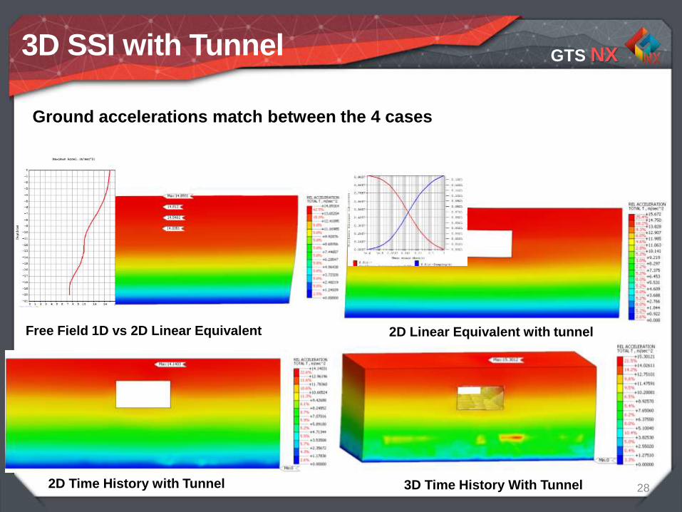
Free Field 1D vs 2D Linear Equivalent
3D SSI with Tunnel
2D Linear Equivalent with tunnel
2D Time History with Tunnel 3D Time History With Tunnel
Ground accelerations match between the 4 cases

GTS NX
29
Axial Forces match for 3
cases
3D SSI with Tunnel
2D Linear Equivalent with tunnel
2D Time History with Tunnel 3D Time History With Tunnel
GTS NX
30
• Análisis Pushover de un marco tridimensional usado para diseño. Puede ser utilizado para concreto reforzado, acero
estructural y secciones compuestas de concreto-acero.
• Diseño basado en desempeño por FEMA, Eurocódigo 8 y Mampostería
Análisis Pushover para Mampostería
Definir materiales no lineales de rotulasEstado de Rótulas y Curva de Capacidad
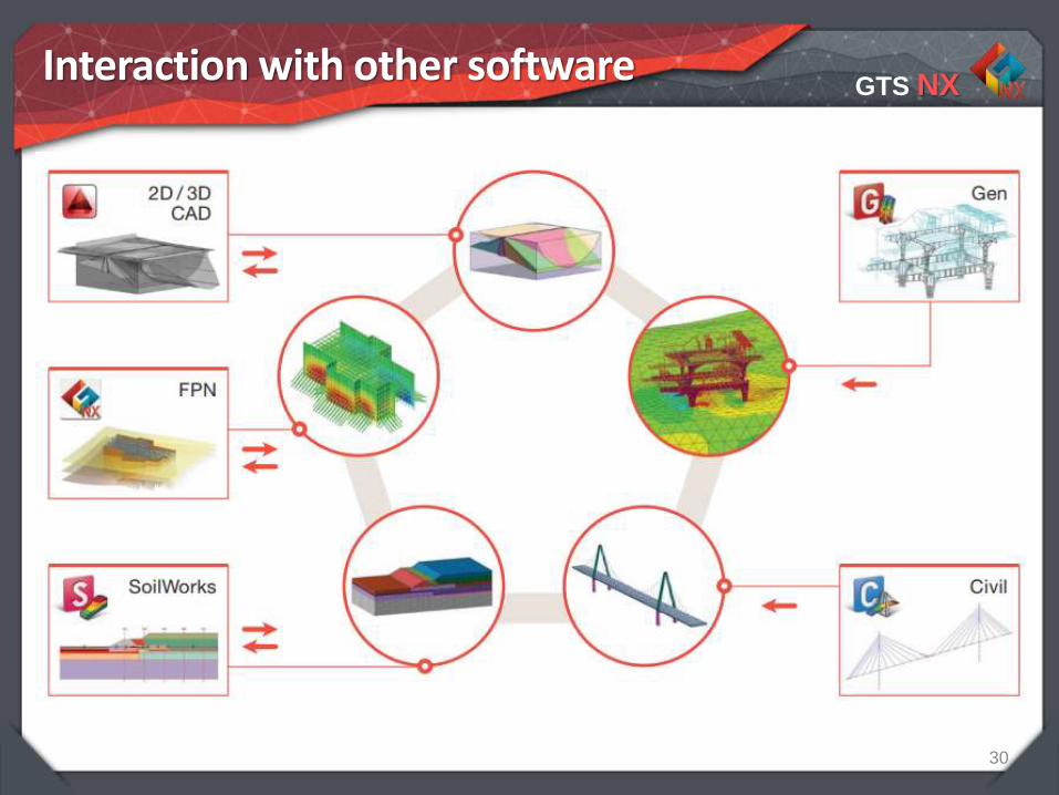
Interaction with other software

GTS NX
31
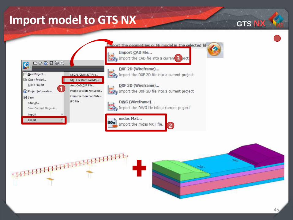
Import model to GTS NX
1. Export file from midas GEN in MXT format
2. Open and Import structure3. Open CAD file into midas GTS
NX
Create GTS NX file with building
1
3
2
2
3

GTS NX
32
Apply Boundary Conditions
1. Boundary > Constraint > Advanced: Assign Z rotation restriction to piles for stability
Boundary Conditions
2
1

GTS NX
33
SSI Results
Results for Nonlinear Time History is within 5%. Max of 15.5 m/sec^2
1. Main Menu> Analysis Case > Perform…
2. Select Nonlinear Time History>Ok3. Results > Abs Max > Relative
Acceleration Total
Procedure
3
1

GTS NX
34
TH Results for GTS NX
• Check Max case for moments YMax 156 kN/m
• Check Max case for axial forces Max: 1702 kN
• Check Max case for displacementsMax: 12.49 cm

Integrated Solver Optimized for the next generation 64-bit platform
Finite Element Solutions for Geotechnical Engineering
Results comparison between SSI Methods

GTS NX
36
Compare results on foundation
Results comparison between methodsMax GEN GTS NX % Diff
Axial Force (kN) 1269 1702 34%
Moments Y (kN/m) 1109 1487 34%

GTS NX
37
Compare results on full structure
Results comparison between methods
Max GEN GTS NX % Diff
Displacements (mm) 425 418 1%
Axial Force (kN) 3915 3962 1%
Moments Y (kN/m) 1109 1487 34%
Structure Period (s) 1.501 1.625 8%

GTS NX
38
3D SSI

GTS NX
39
Initial Civil model dimensions

GTS NX
40
Add Soil Springs Supports
GTS NX
41
Time History Analysis Case
3
1
2

GTS NX
42
Results for TH in Civil using PY springs
Max Axial forces on structure (kN)
Max moments on structure (kN/m)

GTS NX
43
Results for TH in Civil using PY springs
Max displacements (cm)
Max Shear Forces (Kn)

GTS NXSubstructure/Indirect Method
The substructure-only approach:http://Northamerica.midasuser.com > Training > Review Courses
http://Latinamerica.midasuser.com > SesionesWeb> Anteriores
GTS NX
45
Import model to GTS NX
1
3
2

GTS NX
46
Mesh CAD in 3D elements

GTS NX
47
Dynamic results for imported bridge
Max Axial forces on structure
Max moments on structure

GTS NX
48
Results Comparison
GTS NX
49
Conclusion
• Midas Gen has internal PY curves in order to easily apply soil springs and run soil structure interaction through substructure method. For Static Load Cases, this is sufficient.
• Substructure Method cannot accurately capture the non linear behavior experienced by the foundation and surrounding ground during an earthquake. Results are underestimated by 1/3.
• Eigenvalue period of main vibration mode shows ~10% difference.
• Midas GTS NX can import full structure from midas Gen to run SSI through Direct Method. However, since the ground is modeled in 3D, it must first be calibrated through comparison of ground response analysis like Free Field and Linear Equivalent.

GTS NX
50
END

![midas DShop Auto-drafting Module for midas Gen 01 02admin.midasuser.com/UploadFiles2/84/Dshop_catalog.pdf · Auto-drafting Module for midas Gen [midas Gen Design Results] [midas DShop](https://static.fdocuments.in/doc/165x107/5ade06cd7f8b9a9a768db6e7/midas-dshop-auto-drafting-module-for-midas-gen-01-module-for-midas-gen-midas-gen.jpg)
![IMPROVING RESILIENCE, SAFETY, AND SERVICE LIFE ......CSiBridge Midas GTS NX No Soil –Foundation Standalone Solve: [k]{x} + [M]{a} = 0 Seismic Analyses and Design: Standalone Foundation](https://static.fdocuments.in/doc/165x107/60e90789c029d00f190a0181/improving-resilience-safety-and-service-life-csibridge-midas-gts-nx-no.jpg)


![MIDAS/GTS Program Application [1] - geoeng.si Applications Europe v2.pdf · 2 MIDAS/GTS Modelling Pre-processing Global model overview Details of the shaft mesh Post-processing Principal](https://static.fdocuments.in/doc/165x107/5aae92917f8b9a5d0a8c4e87/midasgts-program-application-1-applications-europe-v2pdf2-midasgts-modelling.jpg)