SOIL STRUCTURE INTERACTION ANALYSIS FOR INTEGRAL ABUTMENT...
9
SOIL STRUCTURE INTERACTION ANALYSIS FOR INTEGRAL ABUTMENT BRIDGE SYSTEM by Pruthvi Chowdary, Pallavi Ravishankar, Neelima Satyam in Proceedings of Indian Geotechnical Conference IGC-2014 Report No: IIIT/TR/2014/-1 Centre for Earthquake Engineering International Institute of Information Technology Hyderabad - 500 032, INDIA December 2014
Transcript of SOIL STRUCTURE INTERACTION ANALYSIS FOR INTEGRAL ABUTMENT...

SOIL STRUCTURE INTERACTION ANALYSIS FOR
INTEGRAL ABUTMENT BRIDGE SYSTEM
by
Pruthvi Chowdary, Pallavi Ravishankar, Neelima Satyam
in
Proceedings of Indian Geotechnical Conference IGC-2014
Report No: IIIT/TR/2014/-1
Centre for Earthquake EngineeringInternational Institute of Information Technology
Hyderabad - 500 032, INDIADecember 2014
Proceedings of Indian Geotechnical Conference IGC-2014
December 18-20, 2014, Kakinada, India
SOIL STRUCTURE INTERACTION ANALYSIS FOR INTEGRAL ABUTMENT
BRIDGE SYSTEM
Pruthvi Chowdary, Graduate student, IITH, [email protected]
Pallavi Ravishankar B., PhD student, IIITH, [email protected]
Neelima Satyam D.,Assistant Professor, Geotechnical Engineering Laboratory, Earthquake Engineering
Research Centre, International Institute of Information Technology Hyderabad (IIITH), INDIA.
ABSTRACT: Integral Abutment Bridges (IABs) are jointless bridges whereby the deck is continuous and
monolithic with abutment walls. Their principal advantages are derived from the absence of expansion/contraction
joints, making them the most cost-effective system in terms of construction, maintenance and longevity. It is one of
the challenging tasks to achieve the soil structure interaction between the piles and the surrounding soil of the
integrated bridge system. In this research paper numerical model is developed using appropriate finite element
software for both the basic system with SSI and without SSI and dynamic analysis is carried out to understand the
importance of the soil pile interaction in the considered bridge system. The parametric study including different soil
types, different type of connections between pile and abutment, effect of water table, different earthquake loading
and the results are compared for both the conditions including SSI and without SSI. The main objective of this
study to observe the trends in bending moment, deflection in longitudinal girders and in piles subjected to the given
dynamic loading. The study concluded that the temperature effects are more significant in case of integral abutment
bridges; however the changes in soil properties behind the abutment and around the piles affect significantly the
performance of super structure.
INTRODUCTION
Integral Abutment Bridges (IABs) are Joint less
Bridges in which the deck slab is continuous and
monolithic with abutment walls. This system of
bridges is proved to be more cost-effective in
terms of construction, maintenance and longevity
due to the absence of expansion/contraction joints
and joint bearing which is the prime factor
increases the maintenance cost as prevent the
corrosion of structure due to water seepage
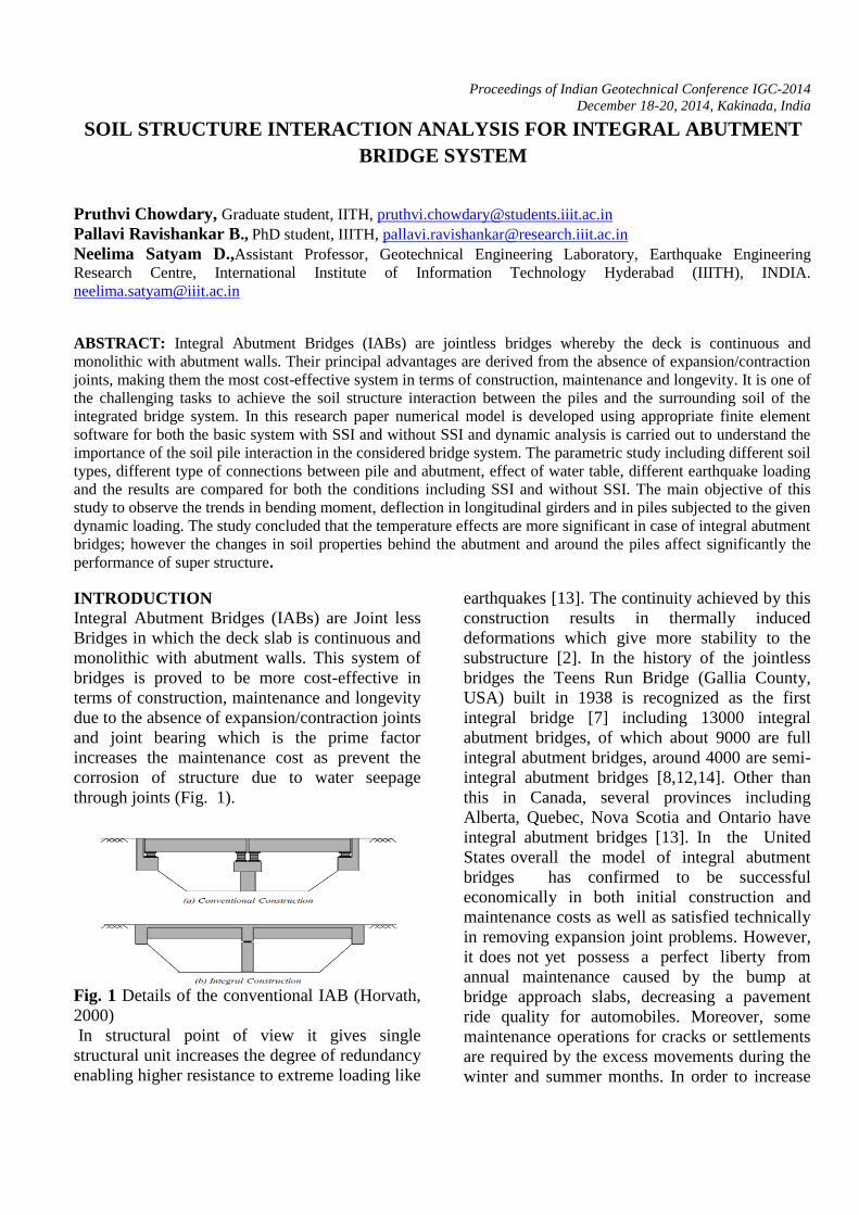
through joints (Fig. 1).
Fig. 1 Details of the conventional IAB (Horvath,
2000)
In structural point of view it gives single
structural unit increases the degree of redundancy
enabling higher resistance to extreme loading like
earthquakes [13]. The continuity achieved by this
construction results in thermally induced
deformations which give more stability to the
substructure [2]. In the history of the jointless
bridges the Teens Run Bridge (Gallia County,
USA) built in 1938 is recognized as the first
integral bridge [7] including 13000 integral
abutment bridges, of which about 9000 are full
integral abutment bridges, around 4000 are semi-
integral abutment bridges [8,12,14]. Other than
this in Canada, several provinces including
Alberta, Quebec, Nova Scotia and Ontario have
integral abutment bridges [13]. In the United
States overall the model of integral abutment
bridges has confirmed to be successful
economically in both initial construction and
maintenance costs as well as satisfied technically
in removing expansion joint problems. However,
it does not yet possess a perfect liberty from
annual maintenance caused by the bump at
bridge approach slabs, decreasing a pavement
ride quality for automobiles. Moreover, some
maintenance operations for cracks or settlements
are required by the excess movements during the
winter and summer months. In order to increase

Pruthvi Choudary, B.Pallavi Ravishankar, D. Neelima Satyam
the confidence in the design and construction of
Integral Abutment Bridges, it is important and
crucial that a comprehensive and exhaustive
performance study be implemented [4,5 and 9].
Geotechnical Issues with Integral Abutment
Bridges:
There are two commonly encountered problems
inherent in the design of integral abutment
bridges that are not structural in nature but rather,
geotechnical (9, 2000). The cyclic loading of the
bridge superstructure due to daily changes in
temperature causes the abutments to rotate about
the base and translate into the soil, thus
developing considerable lateral earth pressure on
the abutments. The magnitude of these soil
pressures can approach or reach the passive state
in the summer when bridge expansion is highest.
Passive earth pressures are large in magnitude
and may exceed the normally consolidated at-rest
state for which an abutment should normally be
designed by at least an order of magnitude.
Failure to design the abutment for the larger
pressures that develop during bridge thermal
expansion can cause structural damage to the
abutment. Adversely, the cost to properly design
the abutment subjected to these higher forces will
increase. The failure in the bridges is generally
happened due to the ratcheting which build-up of
lateral earth pressure as the soil becomes
effectively wedged behind the abutment.
Many researchers proposed a solution to this
issue like use of compressible illusion and
geofoam etc. Using this geofoam configuration
would help with both the settlement behind the
abutment and the tendency toward ratcheting
behaviour[9].
A number of limitations and guidelines have been
presented in order to avoid passive pressure, high
pile stresses [7].
Challenges involved with IABs:
There are a number of limitations in the design of
Integral Abutment Bridges owing to two main
problems. Although the IAB concept has
confirmed to be economical and technically
successful in terms of eliminating expansion joint
problems, it is not free from problems. Bridges
are susceptible due to a complex soil-structure
interaction mechanism involving relative
movement between the bridge abutments and the
backfill, and the piles and adjacent soil. One of
the two major problems observed with IABs is
the development of lateral earth pressures against
the abutments. The other is the void development
under approach slabs [9].
Soil Structure Interaction for Bridge System:
The interaction between the structures,
foundation and soil medium is potential to alter
the actual behavior of any structure considerably
compared with the fixed base analysis. Since,
behavior of the Integral Abutment Bridge is
interdependent between its structural components
and soil medium, it is vital to determine the
relevant parameters of soil to represent its
behavior. In general modeling of the structural
element i.e. superstructure and foundation piles
are rather simple and straightforward compared
to soil medium. The complex behavior of soil due
to its heterogeneous, anisotropic and nonlinear in
force–displacement characteristics need to be
accounted for in its modeling. So the properties
of soil have to be modeled as spring constants
which evaluate the stiffness and flexibility of soil
behind substructure (Fig 2).
Fig. 2 Soil Structure Interaction for IABs

Soil Structure Interaction analysis for Integral Abutment Bridge System
NUMERICAL MODELLING OF
INTEGRAL ABUTMENT BRIDGE
In this research paper 3-Dimensional model of a
prestressed concrete bridge is developed using
finite element software MIDAS CIVIL (V13) for
both fixed and spring support with appropriate
spring constant in accordance with the soil
considered which incorporate the effect of soil
structure interaction (Fig 2). The dimension of
bridge components is taken as per the AASHTO
guidelines (Fig 3, Table 1) and the grade of the
concrete is taken as M35.
Fig. 3 Finite element model for IAB system
Fig. 4 (a.) AASHTO Type IV composite girder
(b.) Finite element model of composite girder
Table 1 Bridge dimensions considered in present
study
Bridge Components Size (m)
Effective span 36
Width 10.36
Deck slab thickness 0.226
Pile length 15 (HP- 10 x 125)
Abutment (d x t) 5 x 1.2
Girder AASHTO guidelines
To capture the real time scenario of soil the
heterogeneity soil is considered including the
four horizontal stratified zones including medium
dense (SAND 1), dense (SAND 2), medium stiff
(CLAY 1) and stiff (CLAY 2). The details of the
each soil layers each type of soil is described in
Fig. 5.
Fig. 5 Details of soil layers considered in
present study
Overburden, 5m
SAND 2, 2.4 m
CLAY 1, 4.8 m
CLAY 2, 4.8 m
SAND 1, 2.4 m
a.
b.

Pruthvi Choudary, B.Pallavi Ravishankar, D. Neelima Satyam
The engineering properties of the soils zones
is detailed in the table 2.The parametric study
is carried out altering these layers and the
interaction response is studied (Table 3 ).
Table 2 Engineering properties of the soil
layer considered in the present study
Param-
eter SAND1 SAND2 CLAY1 CLAY2
Unit
Wt,ϒ
(kN/m3)
19 20 18 19
Unit Wt,ϒsat
(kN/m3) 20 21 19 20
Void
Ratio, e 0.59 0.45 0.76 0.59
Friction
angle, ɸ' 32 38 - -
Earth
pressure
coefficien
t at rest,
K0
0.47 0.38 0.63 0.61
Cohesion,
Cu,
( kN/m2)
- - 40 80
Subgrade
Reaction,
Kh(kN/m
3)
6000 12000 4500 9500
Table 3 Details of parametric study
The model included the partial fix condition
between pile and the abutment and the extended
for both conditions including with and without
SSI. The dynamic analysis is carried out for a
Bhuj (2001, PGA 0.31g) ground motion and the
critical load combination including dead load,
live load, wind load, footpath load, parapet load,
thermal load and ground shaking is applied at the
surface level to simulate the earthquake in the
numerical model. The displacement profile has
been studied for the pile and abutment location
in all principal directions for all analysis cases.
The stresses response is studied in terms of
bending and axial pile stresses and soil
behaviour against the dynamic loading is
predicted in terms of the shear stresses in the
spring.
RESULTS AND DISCUSSION
The dynamic analysis of the IAB system with
multi linear springs is carried out for a Bhuj
ground motion and the response of the integrated
system is estimated in the form of displacements
at the pile and an abutment location (Fig 6). The
response is calculated for both with and without
considering the interaction effect for all possible
analysis cases. The typical deflection profile of
IAb for critical load combination is shown in
Fig. 7.
The rotation at the pile head and abutment
location is also captured in the numerical
analysis (Fig. 8). The soil response is studied
against the ground shaking by means of the
stresses developed in the linear spring attached at
the different nodes of the pile and the backfill
locations at the abutment positions. The response
of the soil (spring at pile top) is shown in Fig. 9
for all analysis cases of soil structure interaction.
Fig. 6. Deflected shape for IABs for all
analysis cases of soil structure interaction
Analysis cases
Soil layers (Sequenced from surface)
Case 1 SAND1,SAND2,CLAY1,CLAY2 Case 2 SAND2,SAND1,CLAY1,CLAY2 Case 3 CLAY1,SAND1,SAND2,CLAY2 Case 4 CLAY2,SAND1,SAND2,CLAY1

Soil Structure Interaction analysis for Integral Abutment Bridge System
Fig. 7 a. Girder b. Pile Displacement in X, Y and
Z directions.
a
.
b.

Pruthvi Choudary, B.Pallavi Ravishankar, D. Neelima Satyam
Fig. 8 a. Girder b. Pile rotation in X, Y and Z
directions.
a.
.
b.

Soil Structure Interaction analysis for Integral Abutment Bridge System
Fig. 9 Soil behaviour against dynamic loading for
analysis Cases considered
The pile drift is estimated at the different
position along the pile length to ensure the
life safety of the bridge for both fixed base
condition and soil structure interaction
effect. Fig 10 shows the pile drift observed
for all analysis cases.
Fig. 10 Drift along the pile length for analysis
Cases considered
RESULTS AND DISCUSSION
The finite element model has been developed for
analyzed for the dynamic loading in the form of
earthquake acceleration as a input shaking .The
response analyzed for the soil heterogeneity to
meet the actual scenario for both the conditions
with and without soil structure interaction in
analysis. Following are few conclusions drawn
from the present study.
Displacements: It is found that the displacement
for pile and girder follows the same typical
profile along each principal direction. In fixed
base analysis for both pile and girder shows
fewer displacements in all directions. In SSI
analysis CASE 4 which includes shows
considerably more displacements in X-direction
for both pile and girder that other cases and Y
and Z direction displacements is found to be
almost same. CASE 3 proves to be a good
combination for least displacement.
Rotation: Girder rotations against the dynamic
loading are found to be negligibly small with
comparison of the pile head rotation. It concludes
that the IAB system with fixed connection
between pile and abutment creates negligibly
small rotational moment in the superstructure.
Rotations observed to be more in all the cases
which includes the soil structure interaction effect
than compared to the fixed base analysis of the
IAB system.
Soil behaviour: With the hysteresis obtained
from the analysis which includes the soil
structure interaction effect the shear stresses
developed in all analysis cases are within the
permissible range and among all cases of analysis
CASE 3 shows the less shear stress.
Pile Drift: The pile drift is estimated at the
different position along the pile length and it has
been observed that fixed base analysis shown the
fixed base analysis shows the least drift as
compared to the SSI analysis. In soil structure
interaction analysis all cases shows the drift
within the safe limit i. e. less than 2 %.
REFERENCES
1. American Association of State Highway and
Transportation Officials. (2012). AASHTO
LRFD Bridge Design Specifications,
Washington, D.C, USA
2. Arockiasamy M., Butrieng N. and Sivakumar
M., (2004), State-of-the-Art of Integral.
3. Arsoy S., (2000), Experimental and Analytical
Investigations of Piles and Abutments of
Integral Bridges, Thesis: Ph.D., Virginia
Shea
r S
tres
s (K
N/m
m2)
Normal Stress (kN/mm2)

Pruthvi Choudary, B.Pallavi Ravishankar, D. Neelima Satyam
Polytechnic Institute and State University, VA,
USA.
4. Bettinger C., (2001), Effects of Thermal
Expansion on a Skewed Semi-Integral Bridge,
Thesis: Master of Science, Ohio University,
Athens, Ohio, USA.
5. Bowles J.E., (1996), Foundation Analysis and
Design, McGraw-Hill, NY, USA.
6. Broms, B. B. and Ingleson, I. (1971). "Earth
pressure against the abutments of a rigid frame
bridge", Géotechnique, The Institution of Civil
Engineers, London, U.K., Vol. 21, No. 1, pp. 15-
28.
7. Burke Jr M.P., (2009), Integral and Semi-
Integral Bridges, Wiley-Blackwell, Oxford, UK.
Conboy, D.W, Stoothoff E. J., 2005, Integral
Abutment Design and Construction.
8. Faraji S., Ting J.M., Crovo D.S. and Ernst H.,
(2001), Nonlinear Analysis of Integral Bridges:
Finite-Element Model, Journal of Geotechnical
and Geoenvironmental Engineering, 127, 454.
9. Horvath, John S. (2000). “Integral-Abutment
Bridges: Problems and Innovative Solutions
Using EPS Geofoam and Other Geosynthetics."
Manhattan College Research Report No. CE/GE-
00-2, Manhattan College, Civil Engineering
Department, Bronx, NY, USA.
10. Kim, W. and J.A. Laman (2009). Load and
Resistance Factor Design for Integral Abutment
Bridges. Ph.D. Dissertation. The Pennsylvania
State University, PA, USA.
11. Krier D., (2009), Modeling of Integral
Abutment Bridges Considering Soil-Structure
Interaction Effects, Thesis: Ph.D., The
University of Oklahoma, Norman, OK, USA.
12. Reese L. C., Isenhower W. M., Wang S. T,
(2006), Analysis and Design of Shallow and
Deep Foundations, John Wiley & Sons, Inc.,
New Jersey, USA and Canada.
13. Shah B.R., (2007), 3D Finite Element Analysis
of Integral Abutment Bridges Subjected to
Thermal Loading, Thesis: Master of Science,
Kansas State University, Manhattan, Kansas,
USA.
14. Reese, L. C., Cox, W. R., and Koch, F. D.
(1974). ‘‘Analysis of Laterally Loaded Piles in
Sand,’’ Proceedings, Offshore Technology
Conference, Houston, TX, Vol. II, Paper No.
2080, pp. 473–484.