Soil Moisture & Temperature & EC Sensor User Manual
23
User Guide ©2008-2020 Seeed Technology Co., Ltd. All rights reserved. solution.seeedstudio.com 1 / 23 Soil Moisture & Temperature & EC Sensor User Manual Product Model: S-Temp&VWC&EC-02 Version: V1.0
Transcript of Soil Moisture & Temperature & EC Sensor User Manual

User Guide
©2008-2020 Seeed Technology Co., Ltd. All rights reserved. solution.seeedstudio.com 1 / 23
Soil Moisture & Temperature & EC Sensor
User Manual
Product Model: S-Temp&VWC&EC-02
Version: V1.0

User Guide
©2008-2020 Seeed Technology Co., Ltd. All rights reserved. solution.seeedstudio.com 2 / 23
Contents
1 Introduction ........................................................................................................................................... 3
2 Specifications ........................................................................................................................................ 4
3 Wiring .................................................................................................................................................... 5
4 Installation ............................................................................................................................................. 6
5 Modbus Communication Protocol ......................................................................................................... 7
5.1 Serial communication parameters ............................................................................................. 7
5.2 Modbus Register ........................................................................................................................ 8
5.3 Detail of Modbus Register ........................................................................................................ 10
5.4 Communication Sample ........................................................................................................... 15
5.4.1 Function number 3 communication sample .................................................................. 15
5.4.2 Function number 4 communication sample .................................................................. 16
5.4.3 Function number 6 communication sample .................................................................. 17
5.4.4 Function number 16 communication sample ................................................................ 18
5.5 CRC16 Check Algorithm .......................................................................................................... 21

User Guide
©2008-2020 Seeed Technology Co., Ltd. All rights reserved. solution.seeedstudio.com 3 / 23
1 Introduction
This S-Temp&VWC&EC-02 soil moisture & EC & temperature sensor is provided with high accurate and
high sensitive. It is an important tool to observe and study the occurrence, evolution, improvement and the
dynamics water of saline soil. By measuring the dielectric constant of the reaction of soil, soil direct stable
real moisture content. This S-Temp&VWC&EC-02 sensor can measure the volume of soil moisture. The
soil moisture measurement method is in line with international standards at present. Apply to the soil
moisture monitoring, scientific experiment, water-saving irrigation, greenhouse vegetables, flowers, grass,
soil, plant cultivation, measured speed of sewage treatment, grain storage, greenhouse control, precision
agriculture.
Features:
● Soil moisture content, electrical conductivity and temperature all in one
● One solution can also be used for fertilizer, and other nutrient solution conductivity matrix
● Electrode using special treatment of the alloy material, can withstand a strong external impact, not
easy to damage
● Completely sealed, acid and alkali corrosion, can be buried in the soil or directly into the water for
long-term dynamic testing
● High precision, fast response, good compatibility, the probe insert design to ensure accurate
measurement, reliable performance
● Perfect protection circuit

User Guide
©2008-2020 Seeed Technology Co., Ltd. All rights reserved. solution.seeedstudio.com 4 / 23
2 Specifications
Soil Temperature
Range -40 ℃ to +80 ℃
Accuracy ±0.5℃
Resolution 0.1 ℃
Soil Moisture
Range From completely dry to fully saturated (from 0% to 100% of saturation)
Accuracy ±2% (0~50%); ±3% (50~100%)
Resolution 0.03% (0~50%); 1% (50~100%)
Electrical Conductivity
Range 0 ~ 10000 μs/cm
Accuracy ±3%
Resolution 10 μs/cm
Temperature Compensation Built in temperature compensation sensor, range 0-50℃
General Parameters
Product Model S-Temp&VWC&EC-02
Interface RS-485
Protocol MODBUS-RTU RS485
Power Supply 3.6 ~ 30V DC
Current Consumption 6mA@24V DC (quiescent dissipation)
IP Rating IP68
Cable Length 5 meters
Operating Temperature -40 ~ 85℃
The material of the probe Anti-corrosion special electrode
Sealing material The black flame retardant epoxy resin
Installation All embedded or probe inserted into the measured medium
Device Weight 210g

User Guide
©2008-2020 Seeed Technology Co., Ltd. All rights reserved. solution.seeedstudio.com 5 / 23
3 Wiring
Yellow RS485+/A/T+
White RS485-/B/T-
Red VCC+, power supply
Black VCC-, power ground
Green SET, V+ (power) when boot module into the "setting mode". Not connected
or connected with the GND when boot into "mode of operation".
Module configuration parameters such as Modbus address, baud rate,
parity, communication protocol is composed of module inside the EEPROM
(power down storage device stores). The specific configuration sometimes
forget these parameters that cannot communicate with the module. In order
to prevent this problem, the module has a special mode called "mode".
When the module is based on the "mode" electric start, the module
communicates with the following parameters:
Fixed Modbus address 0
Communication configuration is 9600, N, 8,1 (9600bps, no parity bit, 8 data
bits, a stop bit)
Communication protocol for Modbus-RTU
Configuration parameters in EEPROM will not because the module into the
"mode" and "will change, when the module is in communication with in the
EEPROM configuration parameter is still running mode".

User Guide
©2008-2020 Seeed Technology Co., Ltd. All rights reserved. solution.seeedstudio.com 6 / 23
4 Installation
Because of the direct determination of the soluble salt ions in the soil, the water content of the soil can be
higher than about 20%, and the soluble ions in the soil can correctly reflect the electrical conductivity of
the soil. In the long-term observation, after irrigation or rainfall measured values are close to the true level.
If the velocity measurement, first in the tested soil watering, to be full of water permeability were measured.
(1) Rapid measurement method: selected measurement locations, avoid the rocks, to ensure that the
needle will not touch the stones like hard object, according to the required depth of cut open the surface
soil, maintain the tightness degree of the original soil below the sensor body, clenched vertically
inserted into the soil, can not be inserted before and after shaking, ensure the close contact with the
soil. A measuring point within a small range test should repeatedly averaging.
(2) Buried in the underground measurement method: vertical drilling diameter greater than 20 cm depth
of pit, according to the measurement needs, then the sensor wire inserted into the pit wall in a given
level of depth, the pit landfill compaction, ensure the close contact with the soil. Stable after a period
of time, can be last for days, months or even longer to measure and record.
If the surface measurement is hard, should first hole (diameter should be less than the diameter of the
probe), and then inserted into the soil and the soil compaction and measurement; sensor should prevent
violent vibration and impact, but not with a hard object percussion. Because the sensor for black package,
in the strong sunlight will make the sensor to make sharp warming (up to over 50 ℃), in order to prevent
the temperature measurement of high temperature impact sensor, please pay attention to sun protection
in the field or fields.

User Guide
©2008-2020 Seeed Technology Co., Ltd. All rights reserved. solution.seeedstudio.com 7 / 23
5 Modbus Communication Protocol
5.1 Serial communication parameters
Modbus is a serial communication protocol, Modicon programmable logic controller (PLC) for the use of
published. It has become the industry standard communication protocols, and is now quite common
connection between industrial electronic equipment. Modbus has ex-tensive application in the industrial
field. Modbus protocol is a master / slave framework agreement. A node is the master node, other nodes
using the Modbus protocol in communication from node. Each slave device has a unique address.
S-Temp&VWC&EC-02 sensor with RS485 interface, support Modbus protocol. The communication
parameters to factory default values for: baud rate 9600 BPS, one start bit, 8 data bits, no parity, one stop
bit. Communication protocol is Modbus RTU protocol. Communication parameters can be changed by the
setup program or MODBUS command, after the communication parameters are changed, the sensor is
required to re - enter the sensor to be effective.

User Guide
©2008-2020 Seeed Technology Co., Ltd. All rights reserved. solution.seeedstudio.com 8 / 23
5.2 Modbus Register
Parameter name Register address
(HEX / DEC)
Parameter type Modbus function
number
Parameter range and description
TEMPRATURE 0x0000 /0 INT16, read 3/4 -4000-8000 corresponds to -40.00 ~
80.00℃.
VWC 0x0001 /1 UINT16, read 3/4 0-10000 corresponds to 0-100%
EC 0x0002 /2 UINT16, read 3/4 0-20000 corresponds to 0-20000us/cm
SALINITY 0x0003 /3 UINT16, read 3/4 0-20000 corresponds to 0-20000mg/L
TDS 0x0004 /4 UINT16, read 3/4 0-20000 corresponds to 0-20000mg/L
EPSILON 0x0005 /5 UINT16, read 3/4 0-8200 corresponds to
0.00~82.00
SOIL TYPE 0x0020 /32 UINT16, read-write 3/6/16 0-3
0: Mineral soil
1: sandy soil
2: clay
3: organic soil
TEMP UNIT 0x0021 /33 UINT16, read-write 3/6/16 0:℃
1:℉
EC&TEMP COFF 0x0022 /34 UINT16, read-write 3/6/16 0-100 corresponds to 0.0%-10.0%
SALINITY COFF 0x0023 /35 UINT16, read-write 3/6/16 0-100 corresponds to 0.00-1.00
TDS COFF 0x0024 /36 UINT16, read-write 3/6/16 0-100 corresponds to 0.00-1.00
Modbus ADDRESS 0x0200 /512 UINT16, read-write 3/6/16 0-255
BAUDRATE 0x0201 /513 UINT16, read-write 3/6/16 0-6
0:1200bps
1:2400bps
2:4800bps
3:9600bps
4:19200bps

User Guide
©2008-2020 Seeed Technology Co., Ltd. All rights reserved. solution.seeedstudio.com 9 / 23
5:38400bps
PROTOCOL 0x0202 /514 UINT16, read-write 3/6/16 0~1
0: Modbus RTU
1: Modbus ASCII
PARITY 0x0203 /515 UINT16, read-write 3/6/16 0-2
0: No parity bit
1: even parity check
2: Odd Parity bit
DATABITS 0x0204 /516 UINT16, read-write 3/6/16 1
1:8 data bits
STOPBITS 0x0205 /517 UINT16, read-write 3/6/16 0-1
0:1 Stop bit
1:2 Stop bit
RESPONSE
DELAY
0x0206 /518 UINT16, read-write 3/6/16 0-255 corresponds to the 0-2550
milliseconds sensor to receive the host
request for a period of time and then the
delay response. The time delay for
setting the value of *10 milliseconds. Set
to 0 when no delay.
ACTIVE OUTPUT
INTERVAL
0x0207 /519 UINT16, read-write 3/6/16 0-255 corresponds to 0-255 seconds
does not require the host to request, the
sensor to send data at a fixed time
interval. The time interval is set value * 1
second. Set to 0 when the active output
function is prohibited.

User Guide
©2008-2020 Seeed Technology Co., Ltd. All rights reserved. solution.seeedstudio.com 10 / 23
5.3 Detail of Modbus Register
TEMPERATURE
Parameter range -4000-8000 corresponds to -40.00~80.00℃ Default: none
Parameter storage none
Meaning: the measured value of the temperature, negative for complement representation.
For example: if the return value is 0702H (of 16 hexadecimal, source code), the first byte is 07, the
second byte and the low byte is 02h, then the temperature for the measured value (07H*256 02h)
/100=17.94℃.
If the return value is FF05H (16 - band, the complement), the first byte is FFH, low second byte is 05H,
then temperature measurement value ((FFH*256 05H) -FFFFH-1H) / 100 = FF05H-FFFFH-1H Celsius
/100=-2.5℃.
VWC --- volumetric water content
Parameter range 0-10000 corresponds to 0-100% Default: none
Parameter storage None
Significance: volumetric water content measurements.
For example: if the return value is 071DH (16 Decimal), the first byte of the high byte is 07H, second
bytes of low byte is 1DH, then the measured value is (1DH 07H*256) /10000= (7*256 29) =1821.
representative volume water content is 18.21%.
EC --- electrical conductivity
Parameter range 0-20000 corresponds to 0-20000us/cm Default: none
Parameter storage None
Significance: electrical conductivity measurement.
For example: if the return value is 071DH (in hexadecimal), the first byte is 07, the second byte and the
low byte is 1dh, then conductivity measurement value (07H*256 1dh) / 10000 = (7*256 29) on behalf of
the =1821. soil conductivity 1821us/cm

User Guide
©2008-2020 Seeed Technology Co., Ltd. All rights reserved. solution.seeedstudio.com 11 / 23
SALINITY
Parameter range 0-20000 corresponds to 0-20000mg/L Default: none
Parameter storage None
Significance: Salinity Measurement.
For example: if the value returned is 071DH (16 Decimal), the first byte of the high byte is 07H, the
second byte low byte is 1DH, then the salinity measurement value (1DH 07H*256) /10000= (7*256 29)
=1821. on behalf of the soil salinity is 1821mg/L
TDS--- total dissolved solids
Parameter range 0-20000 corresponds to 0-20000mg/L Default: none
Parameter storage None
Significance: TDS measurement value.
For example: if the value returned is 071DH (16 Decimal), the first byte of the high byte is 07H, second
bytes of low byte is 1DH, then the TDS measurement value (1DH 07H*256) /10000= (7*256 29) =1821.
on behalf of TDS 1821mg/L.
EPSILON--- dielectric constant
Parameter range 0-8200 corresponds to 0.00-82.00 Default: none
Parameter storage None
Meaning: dielectric constant.
For e xample: if the value returned is 071DH (16 Decimal), the first byte is 07H, the second byte low
byte is 1DH, then the measured value is (1DH 07H*256) /10000= (7*256 29) =1821. to represent the
dielectric constant of 18.21.
TEMP UNIT--- degree unit
Parameter range 0:℃
1:℉
Default: 0
Parameter storage None
Significance: unit of temperature.

User Guide
©2008-2020 Seeed Technology Co., Ltd. All rights reserved. solution.seeedstudio.com 12 / 23
EC TEMP COFF
Parameter range 0-100 corresponds to 0.0%-10.0% Default: 20(2%)
Parameter storage None
Significance: the temperature compensation coefficient of electrical conductivity
SALINITY COFF
Parameter range 0-100 corresponds to 0.00-1.00 Default: 55(0.55)
Parameter storage None
Significance: Salinity / conductivity compensation coefficient
TDS COFF
Parameter range 0-100 corresponds to 0.00-1.00 Default: 50(0.50)
Parameter storage None
Significance: TDS/ conductivity compensation coefficient
SLAVE ADDR --- Modbus address
Parameter range 0-255 Default:1
Parameter storage Immediate storage
Modbus address can be set to 0-255. When outside of the module address the dip switch setting to
address 0, using the contents of the register as a slave address. After setting need to re power or use
the rst command restart module, the entry into force of this address. The use of the command to
change the module address does not need to open the cabinet can be arranged.
BAUDRATE
Parameter range 0-5
0:1200bps
1:2400bps
2:4800bps
3:9600bps
Default:3

User Guide
©2008-2020 Seeed Technology Co., Ltd. All rights reserved. solution.seeedstudio.com 13 / 23
4:19200bps
5:38400bps
Parameter storage Immediate storage
PROTOCOL --- Serial communication Protocol
Parameter range 0~1
0:Modbus RTU
1:Modbus ASCII
Default:0
Parameter storage Immediate storage
PARITY --- Serial communication Check bit
Parameter range 0-2
0:none
1: even parity check
2: Odd parity check
Default:0
Parameter storage Immediate storage
DATA BITS
Parameter range 1
1:8 data bits
Default:1,Only
supports 8 data bits,
the other is invalid
Parameter storage Immediate storage
STOP BITS
Parameter range 0-1
0:1 stop bit
1:2 stop bits
Default:0
Parameter storage Immediate storage

User Guide
©2008-2020 Seeed Technology Co., Ltd. All rights reserved. solution.seeedstudio.com 14 / 23
RESPONSE DELAY
Parameter range 0-255 Default:0
Parameter storage Immediate storage
Serial communication delay response used in the following circumstances: when the host sends a
request command, delay module (RESPONSEDELAY*10 milliseconds), then the response data is
returned to the host. For example, to set up RESPONSEDELAY=5, so delay module 5*10=50
millisecond response requesting host. Set to 0 for no delay an immediate response. This command is
mainly used to host from RS485 transmission switch state to the receiving state relatively slow speed of
occasions.
ACTIVE OUTPUT INTERVAL
Parameter range 0-255 Default:0
Parameter storage Immediate storage
Serial communication active output time interval used in the following circumstances: hosts that do not
need to send a request command module active output response data and output interval for
ACTIVEOUTPUTINTERVAL second, such as setting ACTIVEOUTPUTINTERVAL=5. So module every
5 seconds according to set up the communication protocol of a debate output data. Set to 0 when the
active output is invalid, the main request before response. This command is mainly used in GPRS
wireless transmission, terminal active node data transmission occasions.
Note: when the active output data is set, only one module can be connected on the RS485 bus.

User Guide
©2008-2020 Seeed Technology Co., Ltd. All rights reserved. solution.seeedstudio.com 15 / 23
5.4 Communication Sample
In the following instructions, the data at the beginning of the 0x or the ending of the H is a 16 - band data.
Modbus protocol with two common types of registers:
(1) To maintain the register, storage data is not lost, it is read and write. Usually with function number 3
(0x03) read, use function number 6 (0x06) or 16 (0x10) write.
(2) The input registers are used to store a number of read - only physical variables, such as temperature
values, that are read - only and usually read with a function number 4 (0x04).
5.4.1 Function number 3 communication sample
Common request format:AA 03 RRRR NNNN CCCC
AA 1 byte Address, 0-255
03 1byte Function number 3
RRRR 2byte Start register address, high byte in front
NNNN 2byte read the number of registers N, high byte in the front
CCCC 2byte CRC CHECK
Common request format:AA 03 MM VV0 VV1 VV2 VV3… CCCC
AA 1byte Address, 0-255
03 1byte Function number 3
MM 1byte Returns the number of data byte in the register value
VV0,VV1 2byte Returns the first register value
VV2,VV3 2byte Returns the second register value
… … Returns the “N” register value (N=MM/2)
CCCC 2byte CRC CHECK
For example: to read register 0x0200-0x0201, namely from the machine address and baud rate for
example
Ask:01 03 0200 0002 C5B3
Address 1byte 0x01
Function number 1byte 0x03
Start register
address
2byte 0x0200

User Guide
©2008-2020 Seeed Technology Co., Ltd. All rights reserved. solution.seeedstudio.com 16 / 23
Register number 2byte 0x0002
Check 2byte 0xC5B3
Respond:01 03 04 00 01 00 03 EB F2
Address 1byte 0x01
Function number 1byte 0x03
Effective byte
number
1byte 0x04
Slave address
register value
2byte 0x00 (From machine address high byte)
0x01 (From machine address low byte)
The baud rate
register value
2byte 0x00 (High baud rate byte)
0x03 (low baud rate byte)
Check 2byte 0xEBF2
5.4.2 Function number 4 communication sample
Common request format:AA 04 RRRR NNNN CCCC
AA 1byte Address, 0-255
04 1byte Function number4
RRRR 2byte Start register address, High byte in front
NNNN 2byte o read the number N Register, high byte in the front
CCCC 2byte CRC CHECK
Common request format:AA 04 MM VV0 VV1 VV2 VV3… CCCC
AA 1byte Address, 0-255
04 1byte Function number4
MM 1byte Returns the number of data byte in the register value
VV0,VV1 2byte Returns the first register value
VV2,VV3 2byte Returns the second register value
… … Returns the “N” register value (N=MM/2)
CCCC 2byte CRC CHECK

User Guide
©2008-2020 Seeed Technology Co., Ltd. All rights reserved. solution.seeedstudio.com 17 / 23
For example: to read the register 0x0000-0x0003, that reads the temperature, water content, electrical
conductivity value
Ask:01 04 0000 0003 B00B
Address 1byte 0x01
Function number 1byte 0x04
Start register
address
2byte 0x0000
Register number 2byte 0x0003
Check 2byte 0xB00B
Respond:01 04 06 08 90 0E 93 02 4E D2 57
Address 1byte 0x01
Function number 1byte 0x04
Effective byte
number
1byte 0x06
Temperature
register value
2byte 0x08
0x90
Volume water
content register
value
2byte 0x0E
0x93
Conductivity
register value
2byte 0x02
0x4E
Check 2byte 0xD257
5.4.3 Function number 6 communication sample
Common request format:AA 06 RRRR VVVV CCCC
AA 1byte Address, 0-255
06 1byte Function number6
RRRR 2byte Register address, high byte in front
VVVV 2byte To write the value of the register, the high byte is
in the front

User Guide
©2008-2020 Seeed Technology Co., Ltd. All rights reserved. solution.seeedstudio.com 18 / 23
CCCC 2byte CRC CHECK
Common request format:AA 06 RRRR VVVV CCCC
AA 1byte Address, 0-255
06 1byte Function number6
RRRR 2byte Register address, high byte in front
VVVV 2byte To write the value of the register, the high byte is
in the front
CCCC 2byte CRC CHECK
For example: to write register 0x0021, namely the temperature unit for Fahrenheit cases
Ask:01 06 0021 0001 1800
Address 1byte 0x01
Function number 1byte 0x06
Start register
address
2byte 0x0021
Register number 2byte 0x0001
Check 2byte 0x1800
Respond:01 06 0021 0001 1800
Address 1byte 0x01
Function number 1byte 0x06
Start register
address
2byte 0x0021
Register number 2byte 0x0001
Check 2byte 0x1800
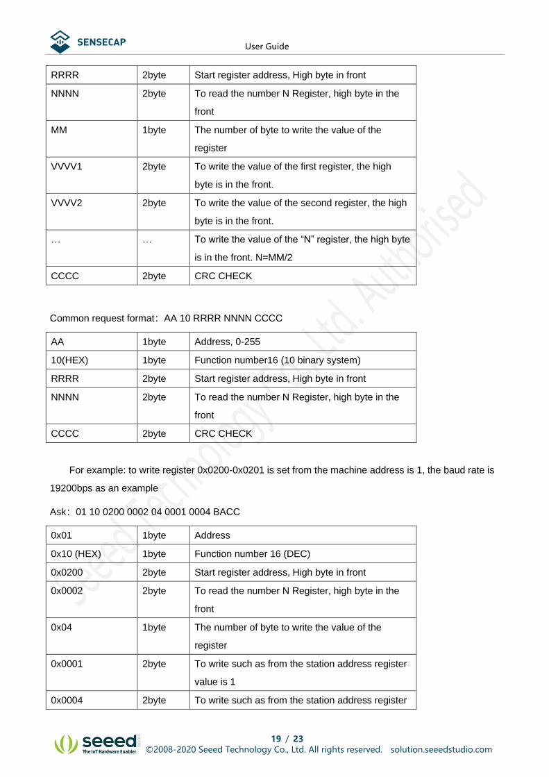
5.4.4 Function number 16 communication sample
Common request format:AA 10 RRRR NNNN MM VVVV1 VVVV2 …CCCC
AA 1byte Address, 0-255
10 (HEX) 1byte Function number16 (10 binary system)
User Guide
©2008-2020 Seeed Technology Co., Ltd. All rights reserved. solution.seeedstudio.com 19 / 23
RRRR 2byte Start register address, High byte in front
NNNN 2byte To read the number N Register, high byte in the
front
MM 1byte The number of byte to write the value of the
register
VVVV1 2byte To write the value of the first register, the high
byte is in the front.
VVVV2 2byte To write the value of the second register, the high
byte is in the front.
… … To write the value of the “N” register, the high byte
is in the front. N=MM/2
CCCC 2byte CRC CHECK
Common request format:AA 10 RRRR NNNN CCCC
AA 1byte Address, 0-255
10(HEX) 1byte Function number16 (10 binary system)
RRRR 2byte Start register address, High byte in front
NNNN 2byte To read the number N Register, high byte in the
front
CCCC 2byte CRC CHECK
For example: to write register 0x0200-0x0201 is set from the machine address is 1, the baud rate is
19200bps as an example
Ask:01 10 0200 0002 04 0001 0004 BACC
0x01 1byte Address
0x10 (HEX) 1byte Function number 16 (DEC)
0x0200 2byte Start register address, High byte in front
0x0002 2byte To read the number N Register, high byte in the
front
0x04 1byte The number of byte to write the value of the
register
0x0001 2byte To write such as from the station address register
value is 1
0x0004 2byte To write such as from the station address register

User Guide
©2008-2020 Seeed Technology Co., Ltd. All rights reserved. solution.seeedstudio.com 20 / 23
value is 4
0xBACC 2byte CRC CHECK
Respond:01 10 0200 0002 4070
0x01 1byte Address
0x10 (HEX) 1byte Function number16 (DEC)
0x0200 2byte Start register address, high byte in the front
0x0002 2byte To read the number N Register, high byte in the
front
0x4070 2byte CRC CHECK

User Guide
©2008-2020 Seeed Technology Co., Ltd. All rights reserved. solution.seeedstudio.com 21 / 23
5.5 CRC16 Check Algorithm
//-----------------------------------------------------------------------------
// CRC calculation of C51 language function is as follows
// Enter the parameter 1:snd, to be the name of the byte Check array
// Input parameters 2:num, the total number of Check to be byte
// Function return value: Check and
//-----------------------------------------------------------------------------
unsigned int calc_crc16 (unsigned char *snd, unsigned char num)
{
unsigned char i, j;
unsigned int c,crc=0xFFFF;
for(i = 0; i < num; i ++)
{
c = snd[i] & 0x00FF;
crc ^= c;
for(j = 0;j < 8; j ++)
{
if (crc & 0x0001)
{
crc>>=1;
crc^=0xA001;
}
else
{
crc>>=1;
}
}
}
return(crc);

User Guide
©2008-2020 Seeed Technology Co., Ltd. All rights reserved. solution.seeedstudio.com 22 / 23
For example: to read the register 0x0000-0x0002, that reads the temperature, water content, electrical
conductivity value
Host Ask:01 0400000003 B00B (8 byte)
Address 1byte 0x01
Function number 1byte 0x04
Start register address 2byte 0x0000
Register number 2byte 0x0003
Check 2byte 0xB00B
When the host needs to send data to the sensor, it will need to send Check data stored in the snd array.
(01 04 00 00 00 03 A total of 6 byte), Among them num=6
Pseudo code as follows:
unsigned char request[8]={01,04,00,00,00,03,00,00};// The last two 00,00 are CHECK CRC
unsigned char num=6;// Calculate the array of the first 6 CRC CHECK byte
unsigned int crc16=0;
crc16= calc_crc16 (request, num);
request[6]= crc16%256;// Store check CRC in an array to be sent
request[7]= crc16/256;
CommPort.Send(request, 8);// Send data through serial port
Sensor Respond:01 04 06 08 90 0E 93 02 4E D2 57 (11 byte)
Address 1byte 0x01
Function number 1byte 0x04
Effective byte number 1byte 0x06
Temperature register value 2byte 0x08
0x90
Volume water content register value 2byte 0x0E
0x93
Conductivity register value 2byte 0x02
0x4E
Check 2byte 0xD257

User Guide
©2008-2020 Seeed Technology Co., Ltd. All rights reserved. solution.seeedstudio.com 23 / 23
When the host receives the 11 byte data returned by the sensor, the following CRC calculation is
performed, where num=11
Pseudo code as follows:
unsigned char response[11]={ 01 04 06 08 90 0E 93 02 4E D2 57};// The last two byte are the CHECK
CRC that the sensor returns
unsigned char num=11;// Calculate the entire return of the 11 CRC CHECK byte
unsigned int crc16=0;
crc16= calc_crc16 (response, num);
if(crc16==0)
{
// Check CRC correctly, you can use the returned data
}
else
{
// Check CRC error, can not be used to return the data
}
To get results back to 0 so the success of Check, if Check fails to return to a nonzero value.If the Check
does not succeed, it shows that the transmission process is wrong, should give up the collected data, re
collection.
The success of the Check, use the following formula to calculate the temperature (negative to
complement representation) and conductivity of H at the end of the 16 hexadecimal data:
temperature=(08H*256+90H)/100=2192/100=21.92 ℃
volumetric water content =(0EH*256+93H)/100=3731/100=37.31%
conductivity =02H*256+4EH=2*256+78 =590 μs/cm