SOIL LIQUEFACTION: PHENOMENON, HAZARDS, REMEDIATION Dr. Farhat Javed Associate Prof. Military...
109
-
Upload
samantha-rice -
Category
Documents
-
view
221 -
download
6
Transcript of SOIL LIQUEFACTION: PHENOMENON, HAZARDS, REMEDIATION Dr. Farhat Javed Associate Prof. Military...


SOIL LIQUEFACTION: PHENOMENON, HAZARDS , REMEDIATION
Dr. Farhat Javed
Associate Prof. Military College of Engg, Risalpur

AIMAIM
• HIGLIGHT THE IMPORTANCE OF LIQUEFACTION IN ENGINEERING PRACTICE

SEQUENCE OF SEQUENCE OF PRESENTATIONPRESENTATION
• Introduction
• Liquefaction phenomenon
• Hazards Associated with Liquefaction • Evaluation of Liquefaction Potential
• Remediation

•During an earthquake seismic waves During an earthquake seismic waves travel vertically and rapid loading of travel vertically and rapid loading of soil occurs under undrained conditions soil occurs under undrained conditions i.e., pore water has no time to move i.e., pore water has no time to move out. In saturated soils the seismic out. In saturated soils the seismic energy causes an increase in pore energy causes an increase in pore water pressures and consequently the water pressures and consequently the effective stresses decrease. This effective stresses decrease. This results in loss of shear strength of soil results in loss of shear strength of soil and soil starts to behave as a fluid. and soil starts to behave as a fluid. This fluid is no longer able to sustain This fluid is no longer able to sustain the load of structure and the structure the load of structure and the structure settles. This phenomenon is known as settles. This phenomenon is known as liquefaction. liquefaction.

The Phenomenon is associated with:The Phenomenon is associated with:• softsoft• youngyoung• water-saturatedwater-saturated• uniformly gradeduniformly graded• fine grained sands and siltsfine grained sands and silts
During liquefaction these soils behave as During liquefaction these soils behave as viscous fluids rather than solids . viscous fluids rather than solids .
This can be better demonstrated by a video This can be better demonstrated by a video clip in which a glass container with clip in which a glass container with saturated sand is resting on a vibrating saturated sand is resting on a vibrating table.table.

GLASS CONTAINER
SATURATED SAND
STRUCTURE


•The phenomenon of liquefaction The phenomenon of liquefaction can be well understood by can be well understood by considering shear strength of considering shear strength of soils. Soils fail under externally soils. Soils fail under externally applied shear forces and the applied shear forces and the shear strength of soil is governed shear strength of soil is governed by the effective or inter-granular by the effective or inter-granular stresses expressed as: stresses expressed as:
Effective stress = (total stress - Effective stress = (total stress - pore water pressure)pore water pressure)
σσ’’ = = σσ -- u u

SShear strength hear strength ττ of soil is given of soil is given as :as :
ττ = c + = c + σ’tan tan φφ
IIt can be seen that a cohesionless t can be seen that a cohesionless soil such as sand will not posses soil such as sand will not posses any shear strength when the any shear strength when the effective stresses approach zero effective stresses approach zero and it will transform into a and it will transform into a liquid state.liquid state.

Contact forces between particles Contact forces between particles give rise to normal stresses that are give rise to normal stresses that are
responsible for shear strength. responsible for shear strength.
This box This box represents represents magnitude of magnitude of pore water pore water pressurepressure
Assemblage of particles

During dynamic loading there is an increase in water During dynamic loading there is an increase in water pressure which reduces the contact forces between the pressure which reduces the contact forces between the
individual soil particles, thereby softening and weakening individual soil particles, thereby softening and weakening the soil deposit. the soil deposit.
Increase in pore pressure due to dynamic loading

HAZARDS ASSOCIATED HAZARDS ASSOCIATED WITH LIQUEFACTION WITH LIQUEFACTION
PHENOMENONPHENOMENON

Historical EvidencesHistorical Evidences
• 1964 Nigata (Japan)1964 Nigata (Japan)• 1964 Great Alaskan 1964 Great Alaskan
earthquake earthquake • Seismically induced soil Seismically induced soil
liquefaction produced liquefaction produced spectacular and devastating spectacular and devastating effect in both of these events, effect in both of these events, thrusting the issue forcefully to thrusting the issue forcefully to the attention of engineers and the attention of engineers and researchers researchers

When liquefaction occurs, the strength of the soil decreases and, the ability of a soil deposit to support foundations for buildings and bridges is reduced …. overturned apartment complex buildings in Niigata in 1964.

Liquefied soil also exerts higher pressure on retaining walls,which can Liquefied soil also exerts higher pressure on retaining walls,which can cause them to tilt or slide. This movement can cause settlement of the cause them to tilt or slide. This movement can cause settlement of the retained soil and destruction of structures on the ground surfaceretained soil and destruction of structures on the ground surface
Kobe Kobe 19951995

Retaining wall damage and lateral spreading, Kobe 1995Retaining wall damage and lateral spreading, Kobe 1995

Increased water pressure can also trigger landslides and cause the Increased water pressure can also trigger landslides and cause the collapse of dams. Lower San Fernando dam suffered an underwater slide collapse of dams. Lower San Fernando dam suffered an underwater slide during the San Fernando earthquake, 1971. during the San Fernando earthquake, 1971.

Sand boils and ground fissures were observed at various sites in Niigata. Sand boils and ground fissures were observed at various sites in Niigata.

Lateral spreading caused the foundations of the Showa bridge in Lateral spreading caused the foundations of the Showa bridge in Nigata ,Japan to move laterally so much that the simply supported spans Nigata ,Japan to move laterally so much that the simply supported spans became unseated and collapsed became unseated and collapsed

Liquefaction-induced soil movements can push foundations out of place Liquefaction-induced soil movements can push foundations out of place to the point where bridge spans loose support or are compressed to the to the point where bridge spans loose support or are compressed to the point of buckling point of buckling
•1964 Alaskan earthquake1964 Alaskan earthquake. .

1995 Kobe earthquake, Japan
The strong ground motions that led to collapse of the Hanshin Express way also caused severe liquefaction damage to port and wharf facilities as can be seen below.

Lateral spreading caused 1.2-2 meter drop of paved surface and local flooding, Kobe 1995.

Alaska earthquake, USA,1964

1957 Lake Merced slide

modest movements during liquefaction produce tension cracks such as those on the banks of the Motagua River
following the 1976 Guatemala Earthquake.

Damaged quay walls and port facilities on Rokko Island. Quay walls have been pushed outward by 2 to 3 meters with 3 to 4 meters deep depressed areas called grabens forming
behind the walls, Kobe 1995.

1999 Chi-Chi (Taiwan) earthquake over 2,400 people were killed, and 11,000 were injured

1999 Chi-Chi (Taiwan) earthquake

1999 Chi-Chi (Taiwan) earthquake

1999 Chi-Chi (Taiwan) earthquake

1999 Chi-Chi (Taiwan) earthquake

Road damaged by lateral spread, near Pajaro River, 1989 Loma Prieta earthquake

Liquefaction failure of shefield dam (1925, california USA)

Liquefaction failure of Tanks at Nigata, Japan)

Chi-Chi earthquake. Among the 467 foundation damage cases reported, 67 cases (14%
were caused by earthquake-induced liquefaction.
Figure 1. Foundation damage survey after the 1999 Chi-Chi earthquake (NCREE, 2000

•Evaluation of Liquefaction
Potential

•The evaluation of liquefaction The evaluation of liquefaction potential of soils at any site potential of soils at any site requires parameters pertaining requires parameters pertaining to:to:
• cyclic loadscyclic loads due to an due to an earthquakeearthquake
• and and •soil propertiessoil properties which describe which describe
the soil resistance under those the soil resistance under those loads.loads.

Normal Field Conditions
Where
σv’ = effective vertical stress
K0= at-rest earth pressure coefficient
K0σv’ = effective horizontal stress

During Earthquake

•Two tests can be used to Two tests can be used to simulate field stress simulate field stress conditionsconditions
• Cyclic direct shear Cyclic direct shear test test
• Cyclic triaxial test Cyclic triaxial test
•

Cyclic Direct Shear Test

Cyclic Triaxial Test

Relation between cyclic direct shear and
cyclic triaxial test (τh/σv) direct shear = Cr (1/2 x σd/σ3’ )triaxial
where; τh = horizontal shear stress (τh/σv) = cyclic stress ratio CSR
σv = vertical stress σd = deviator stress σ3’ = effective confining
pressureCr = Correction faactor obtained
from figure given on next slide


• If relative density in lab is different If relative density in lab is different from field then the equation is from field then the equation is
modified as followsmodified as follows::
(τavg/σv’)= Cr(1/2 x σd/σ3’)triaxial at RD1 x RD2/RD1
• Where Where RD1 is relative density in lab and RD2 is relative density in field

Generally cyclic triaxial test is conducted at various cyclic stress ratios CSR = (1/2 x σd/σ3’) on undisturbed or remolded specimen till liquefaction occurs, and corresponding number of stress cycles is determined. A graph is plotted
between CSR and number of stress cycles.

This graph can be used to read out CSR corresponding to any number of stress cycles and this value is used in following relationship to determine shear resistance that will be mobilized at any depth.
(τavg/σv’)= Cr(1/2 x σd/σ3’)triaxial at RD1 x RD2/RD1

If cyclic tiaxial testing can not be conducted then this Graph can be used to determine CSR from Mean grain
Size D 50

Results of Standard Penetration Test can also be used to determine CSR from this curve.
Subsequently shear resistance of soil against cyclic loading can be determined by:
= CSR x σv ‘
Where,
σv‘ is effective vertical stress

DDETERMINATION OF ETERMINATION OF SHEAR STRESSES SHEAR STRESSES INDUCED BY CERTAIN INDUCED BY CERTAIN EARTHQUAKE IN THE EARTHQUAKE IN THE FIELD BY SIMPLIFIED FIELD BY SIMPLIFIED PROCEDUREPROCEDURE


Since soil prism is assumed to be a rigid Since soil prism is assumed to be a rigid body therefore a correction factor “rbody therefore a correction factor “rDD” ” must be applied as soil is not rigid.must be applied as soil is not rigid.
ττ = r = rDD ( (h ah amaxmax )/g )/g Where, Where,
ττ == shear stress induced during an shear stress induced during an earthquakeearthquake
= = unit weight of soil.unit weight of soil.aamaxmax == maximum acceleration due to maximum acceleration due to earthquakeearthquakegg == acceleration due to gravityacceleration due to gravityhh == height of soil prismheight of soil prism
rrDD = stress reduction factor , a function = stress reduction factor , a function of depth of depth of point being analyzed. It of point being analyzed. It can be obtained from next can be obtained from next slideslide


For an actual earthquake event Acceleration v/s time
relationship (accelerogram) looks like

During an earthquake the During an earthquake the induced cyclic shear induced cyclic shear stresses vary with time. On stresses vary with time. On the contrary in the the contrary in the laboratory shear test the laboratory shear test the specimen is subjected to a specimen is subjected to a uniform cyclic shear stressuniform cyclic shear stress..
To incorporate this effect a multiplication factor of 0.65 has been suggested.

•Seed et al have Seed et al have recommended a weighted recommended a weighted procedure to derive the procedure to derive the number of uniform stress number of uniform stress cycles cycles NNeqeq (at an amplitude (at an amplitude of 65% of the peak cyclic of 65% of the peak cyclic shear stresses i.e. shear stresses i.e. ττcyccyc==0.65 0.65 ττmaxmax) from recorded strong ) from recorded strong ground motion ground motion


This Table can be used to determine equivalent number of stress cycles
for an earthquake of certain magnitude.

The effect of non uniform stress cycles is The effect of non uniform stress cycles is incorporated by determining equivalent incorporated by determining equivalent number of stress cycles for an earthquake and number of stress cycles for an earthquake and shear stresses induced during an earthquake shear stresses induced during an earthquake are computed by the following equation:are computed by the following equation:
ττ = 0.65 r = 0.65 rDD ( (h ah amaxmax )/g )/g Where, Where,
ττ == shear stress induced during an shear stress induced during an earthquakeearthquake
= = unit weight of soil.unit weight of soil.aamaxmax == maximum acceleration due to maximum acceleration due to earthquakeearthquakegg == acceleration due to gravityacceleration due to gravityhh == height of soil prismheight of soil prism
rrDD = stress reduction factor , a function of = stress reduction factor , a function of depth depth of point being analyzed. It can be of point being analyzed. It can be obtained from next obtained from next slideslide

Maps like these Can be used toDetermine maxGround acceleration

•After determining the After determining the cyclic cyclic shear stresses induced by an shear stresses induced by an earthquakeearthquake
and and
the the shear resistance mobilizedshear resistance mobilized at at the point under consideration, a the point under consideration, a graph is plotted between depth graph is plotted between depth and the stresses determined and the stresses determined above.above.
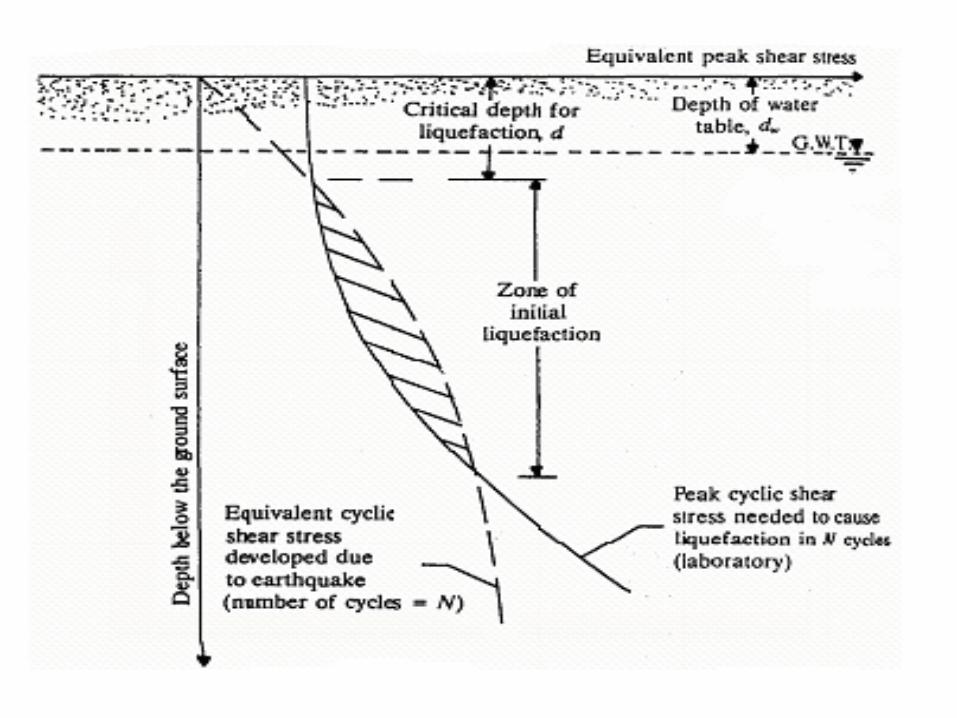

•IIf induced cyclic shear f induced cyclic shear stresses are more than stresses are more than shear resistance shear resistance mobilized, liquefaction mobilized, liquefaction will occur.will occur.

•RESEARCH ON RESEARCH ON KAMRA SANDKAMRA SAND

Soil Stratification developed after SPT and Boring

Compacted Earth Fill
SAND LAYER
SILT LAYER
0.5 m

Sampling being done in Test Pit
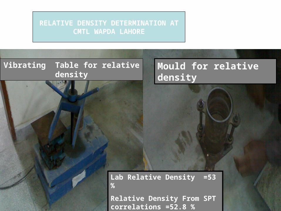
Vibrating Table for relative density
Mould for relative density
Lab Relative Density =53 %
Relative Density From SPT correlations =52.8 %
RELATIVE DENSITY DETERMINATION ATCMTL WAPDA LAHORE

EVALUATION OF LIQUEFACTION

SEISMICITY OF KAMRA CITY

PHA at Kamra = 0.24 g


Sr. No Fault Name
Length (km)
Distance From Kamra(km)
Magnitudeof earthquake From equationlogL=1.02M – 5.77
1 Khairabad Fault 370 3 8.2

It is concluded that an earthquake of Magnitude 7 can occur at Kamra with peak horizontal acceleration of 0.24 g

•Standard Penetration Test (SPT) •Cyclic Triaxial Test.
Evaluation of Liquefaction potential

Hypothesis If water table rises and sand gets saturated then liquefaction will occur under magnitude 7 earthquake

PointDepth
(m)
Shear stress mobilized in field
τ avg (KN/m2)
Shear Resistance
τr (KN / m2 )Remarks
A 1.50 4.17 3.24τavg > τr
(Liquefaction will occur)
B 1.75 4.89 3.24τavg > τr
(Liquefaction will occur)
C 2.00 5.58 4.13τavg > τr
(Liquefaction will occur)
Evaluation Of Liquefaction On the basis of SPT
ττ = 0.65 r = 0.65 rDD ( (h h aamaxmax )/g )/g
= CSR x σv ‘

ANALYSIS ON THE BASIS OF CYCLIC TRIAXIAL TEST.
Analysis on the basis of triaxial was based on the method proposed by SEED AND IDRIS
Shear resistance was computed from the following formula
(τ(τavg/σv’)= Cr(1/2 x σd/σ3’)triaxial at RD1 x RD2/RD1 Cr(1/2 x σd / σ3’ )triaxial x RD2/RD1
τh = Cr(1/2 x σd / σ3’ ) x σv’ x RD2/RD1

0.57

0.255

pointDepth
(m)
Shear stress mobilized in fieldτ avg
(KN/m2)
Shear resistance
by Triaxial
τr (KN / m2 )Remarks
A 1.50 4.17 4.08 τavg > τr
(Liquefaction will
occur)B 1.75 4.89 4.46 τavg > τr
(Liquefaction will
occur)C 2.00 5.58 5.20 τavg > τr
(Liquefaction will
occur)
Analysis By Cyclic Triaxial Test
ττ = 0.65 r = 0.65 rDD ( (h h aamaxmax )/g )/g
(τavg/σv’)=Cr(1/2 x σd/σ3’)triaxial at RD1 x RD2/RD1

It is concluded on the basis of these results that the sand will liquefy under the event of an earthquake of Magnitude 7.

REMEDIATIONHOW CAN LIQUIFACTION HAZARDS BE
REDUCED?

Avoid Liquefaction Susceptible Soils
Build Liquefaction Resistant Structures
Improve the Soil

Avoid Liquefaction Susceptible Soils
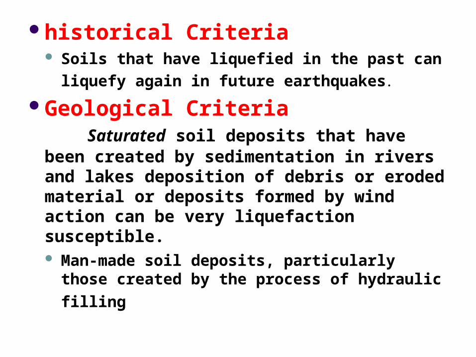
historical Criteria Soils that have liquefied in the past can liquefy
again in future earthquakes. Geological Criteria
Saturated soil deposits that have been created by sedimentation in rivers and lakes deposition of debris or eroded material or deposits formed by wind action can be very liquefaction susceptible. Man-made soil deposits, particularly those
created by the process of hydraulic filling

Compositional Criteria D10 sizes ranging from 0.05 to 1.0 mm ANDa coefficient of uniformity ranging from 2 to 10. Uniformly graded soil deposits
Angularity of particles
Silty soils are susceptible to liquefaction if they satisfy the criteria given below.
Fraction finer than 0.005 mm< 15% Liquid Limit, LL < 35% Natural water content > 0.9 LL Liquidity Index < 0.75

State Criteria
Relative density, Dr
Increasing confining pressure

Build Liquefaction Resistant Structures
HOW CAN LIQUIFACTION HAZARDS BE REDUCED?

Build Liquefaction Resistant Structures It is important that all
foundation elements in a shallow foundation are tied together to make the foundation move or settle uniformly, thus decreasing the amount of shear forces induced in the structural elements resting upon the foundation.

Build Liquefaction Resistant Structures A stiff foundation
mat is a good type of shallow foundation, which can transfer loads from locally liquefied zones to adjacent stronger ground.

Build Liquefaction Resistant Structures Buried utilities, such as
sewage and water pipes, should have ductile connections to the structure to accommodate the large movements and settlements that can occur due to liquefaction. The pipes in the photo connected the two buildings in a straight line before the earthquake

Build Liquefaction Resistant Structures

Improve the Soil
HOW CAN LIQUIFACTION HAZARDS BE REDUCED?

Vibroflotation

Vibroflotation

Improve the Soil
Dynamic Compaction

Stone ColumnsGenerally, the stone column ground improvement method is used to treat
soils where fines content exceeds that acceptable for vibrocompaction

Compaction Piles

Compaction Grouting Compaction grouting is a ground treatment
technique that involves injection of a thick-consistency soil-cement grout under pressure into the soil mass, consolidating, and thereby densifying surrounding soils in-place. The injected grout mass occupies void space created by pressure-densification. Pump pressure, as transmitted through low-mobility grout, produces compaction by displacing soil at depth until resisted by the weight of overlying soils.

Improve the Soil
Drainage techniques

Improve the Soil
Drainage techniques

Improve the Soil

Verification of Improvement
Verification of Improvement
A number of methods can be used to verify the effectiveness of soil improvement. In-situ techniques are popular because of the limitations of many laboratory techniques. Usually, in-situ test are performed to evaluate the liquefaction potential of a soil deposit before the improvement was attempted. With the knowledge of the existing ground characteristics, one can then specify a necessary level of improvement in terms of insitu test parameters.

?

?