SOGEVAC SV200 / SV300 ATEX Cat 2 - Leybold …€¦ · SV200 – SV300 ATEX Cat 2 have been...
64
130001808_002_C0 SV200 & 300 ATEX Cat 2 11/2016 1 / 64 SOGEVAC ® SV200 / SV300 ATEX Cat 2 Single-stage, oil sealed rotary vane pump. Operating Instructions 130001808_002_C0 II (i) 2G b IIB+H2 T3 / (o) 2G IIC T3 (10°C <Ta< 40°C) X Part Numbers 10927A22 1092702A22 10931A22 1093102A22 and their variants.
Transcript of SOGEVAC SV200 / SV300 ATEX Cat 2 - Leybold …€¦ · SV200 – SV300 ATEX Cat 2 have been...

130001808_002_C0 SV200 & 300 ATEX Cat 2 11/2016 1 / 64
SOGEVAC® SV200 / SV300 ATEX Cat 2
Single-stage, oil sealed rotary vane pump. Operating Instructions 130001808_002_C0
II (i) 2G b IIB+H2 T3 / (o) 2G IIC T3 (10°C <Ta< 40°C) X Part Numbers 10927A22 1092702A22 10931A22 1093102A22 and their variants.

130001808_002_C0 SV200 & 300 ATEX Cat 2 11/2016 2 / 64
Contents Important Safety Information ................................................................................... 3
1. Description ......................................................................................................... 5
1.1 Principle of operation ..................................................................................... 5
1.2 Technical characteristics ............................................................................. 10
1.3 Ordering Information .................................................................................... 14
1.4 Connection fittings pump intake .................................................................. 17
1.5 Connection fittings pump gas ballast ........................................................... 17
1.6 Accessories ................................................................................................. 18
1.7 SV + Roots combinations ............................................................................ 18
1.8 Spare parts .................................................................................................. 19
1.9 Lubricants .................................................................................................... 19
2 Transport and Storing ..................................................................................... 20
2.1 Transport and packaging ............................................................................. 20
2.2 Mounting orientation .................................................................................... 20
2.3 Storage ........................................................................................................ 20
3 Installation ........................................................................................................ 21
3.1 Installation ................................................................................................... 21
3.2 Connection to the system ............................................................................ 21
3.3 Electrical connections .................................................................................. 24
3.4 Start-up ........................................................................................................ 31
4 Operation .......................................................................................................... 32
4.1 Operation ..................................................................................................... 32
4.2 Shutdown .................................................................................................... 34
4.3 Ultimate pump pressure .............................................................................. 34
5 Maintenance ..................................................................................................... 35
5.1 Safety Information ....................................................................................... 35
5.2 Maintenance Intervals ................................................................................. 36
5.3 Service at Leybold facilities ......................................................................... 37
5.4 Maintenance Work ....................................................................................... 38
6 Trouble shooting .............................................................................................. 50
7 Spare parts ....................................................................................................... 52
Contents

130001808_002_C0 SV200 & 300 ATEX Cat 2 11/2016 3 / 64
Important Safety Information Indicates procedures that must be strictly observed to prevent hazards to persons. Indicates procedures that must be strictly observed to prevent damage to, or destruction of the product. Emphasises additional application information and other useful information provided within these Operating Instructions. The Leybold SOGEVAC® SV200 – SV300 ATEX Cat 2 have been designed for safe and efficient operation when used properly and in accordance with these Operating Instructions. It is the responsibility of the user to carefully read and strictly observe all safety precautions described in this section and throughout the Operating Instructions. The SOGEVAC® SV200 – SV300 ATEX must only be operated in the proper condition and under the conditions described in the Operating Instructions. It must be operated and maintained by trained ATEX personnel only. Consult local, state, and national agencies regarding specific requirements and regulations. Address any further safety, operation and/or maintenance questions to our nearest office. The SOGEVAC SV 200 & 300 A ATEX Category 2 vacuum pumps have been specifically designed and manufactured to meet the requirements for Equipment-group II Category 2 of the "ATEX" Directive" i.e. Directive 2014/34/EU concerning equipment and protective systems intended for use in potentially explosive atmospheres. Failure to observe the following precautions could result in serious personal injury! SOGEVAC® pumps are not designed: for pumping of aggressive, corrosive gases or gases mixtures ; for pumping of oxygen or other highly reactive gases with a greater concentration than atmospheric concentration (>20%) ; For all these cases, special materials must be used. In case of doubt, please contact Leybold. See also the limits of use indicated in the CE declaration of conformity. Never expose part of the body to the vacuum. There is a danger of injury. Never operate the pump with an open and thus accessible inlet. Vacuum connections as well as oil filling and oil draining openings must not be opened during operation of the pump. When operating pump is hot and some surfaces could reach a temperature higher than 80°C (176°F). There is a risk of burn by touching. Depending on the process involved, dangerous substances and oil may escape from the pump. Take the necessary safety precautions ! When working on the pump system always observe the Operating Instructions. Disconnect the unit from the power supply before starting any work.
Warning Caution Note Warning
Caution
Important Safety Information
Important Safety Information

130001808_002_C0 SV200 & 300 ATEX Cat 2 11/2016 4 / 64
Take appropriate precautions to insure that the pump cannot start. If the pump has pumped hazardous gases it will be absolutely necessary to determine the nature of the hazard involved and take the appropriate safety precautions. Observe all safety regulations ! Take adequate safety precautions prior to opening the intake or exhaust port. Failure to observe the following precautions could result in damage to the equipment! Liquid and solid particles or dust must not enter into the pump. Install the adequate filters, separators and/or condensers. In case of doubt consult Leybold. The intake line of the pump must never be connected to a device with over atmospheric pressure. Design the exhaust line so that no pressure higher than 1,15 bar abs. (0,15 bar rel.) can occur. Corresponding pressure regulating devices to be installed by the user. Exhaust must be collected and gases treated acc. their composition. Operating of the pump without oil or operating with incorrect direction of rotation can destroy the pump. Never use discarded seals. Always assemble using new seals. Respect the instructions concerning environment protection when discarding used oil or exhaust filters ! The pump must be packaged in such a way that it will not be damaged during shipping, and so that no harmful substances can escape from the package. We reserve the right to alter the design or any data given in these Operating Instructions. The illustrations are not binding. It is mandatory that these operating instructions be read and understood prior to the vacuum pump installation and start-up. The SOGEVAC® vacuum pumps have been manufactured according to the newest technical standards and safety regulations. If not installed properly or not used as directed, dangerous situations or damage might occur. Under certain operating conditions, dangerous situations may occur when running the vacuum pump. If this happens, please contact our local office.
Warning
Caution Note

130001808_002_C0 SV200 & 300 ATEX Cat 2 11/2016 5 / 64
1. Description SOGEVAC® pumps are designed for pumping of inert gases in the range of rough vacuum, between atmospheric pressure and end pressure of the pump. When removing condensable vapours, a gas ballast valve must be installed. 1.1 Principle of operation
The SOGEVAC® SV 200 and SV 300 are single- stage, oil-sealed rotary vane pumps. The anti-suckback valve, gas ballast valve, exhaust filter, oil return circuit and oil cooling oil are integrated functional elements. The pumps are driven by a directly flanged motor. The rotor mounted eccentrically in the pump cylinder has three vanes which divide the pump chamber into several compartments. The volume of each changes periodically with the rotation of the rotor. As the rotor rotates, the intake portion of the pumping chamber expands and sucks gas thru the intake port. The gas passes through the dirt trap and the open anti-suckback valve and enters the pump chamber. As the rotor rotates further, the vane separates part of the pump chamber from the intake port. This part of the pump chamber is reduced, and the gas is compressed. At slightly above atmospheric pressure the gas is expelled from the chamber via the exhaust valve. Oil injected into the pump chamber serves to seal, lubricate and cool the pump. The oil entrained with the compressed gas is coarsely trapped in the oil case by deflection. Then fine filtering occurs in the exhaust filter elements. The proportion of oil in the exhaust gas is thus reduced below the visibility threshold (over 99 % entrapment rate). Oil trapped in the exhaust filters is returned to the inlet chamber via an oil return line. To prevent gas flowing at atmospheric pressure from the oil reservoir into the intake port, the oil return line is controlled by a float valve. The oil cycle is maintained by the pressure difference existing between the oil casing (pressure above or equal atmospheric pressure) and the intake port (pressure below atmospheric pressure). On part of the oil is taken from the oil casing and flows via the oil filter bypass to the bearing points of the rotor and to the pump chamber. The other part of oil injected in the pump does not run through the oil filter bypass. A fan running on the motor shaft generates the necessary cooling air. The oil is also fed, thru a cooling coil, or in case of water cooled pumps, flows through a water oil heat exchanger controlled by a thermostatic valve. All SV200 / 300 ATEX pumps are fitted with:
• PT100 temperature sensor • Oil level switch • Oil casing pressure transmitter
Pumps depending of their P/N are equipped with a gas ballast device. If opened, a controlled amount of air so called "gas ballast" is admitted into the pump chamber. This gas ballast prevents condensation (up to the limit of water vapour tolerance specified in the Technical Data) when pumping condensable gases or vapours. There are different types of gas ballast : - standard manual gas ballast, - large gas ballast (10 %), available upon request, - permanent, available upon request. The pump temperature class may vary depending of the GB type. Please check the pump marking !
Note Warning
Description

130001808_002_C0 SV200 & 300 ATEX Cat 2 11/2016 6 / 64
Unintentional venting of the vacuum chamber as well as oil suck back when shutting down the pump are prevented by the integrated anti suck back valve. This valve is not a safety device and its correct operation & tightness can only be assured if the valve plate & sealing zone are kept clean and in good condition. If all returns are to be avoided by all means, it is required to install a vacuum safety valve on the pump suction flange. Please consult us. Inside the pump (process gas) The inside (process gas side) of this vacuum pump is so designed and constructed so as not to present an ignition source in cases of expected malfunction. It is therefore suitable for use in situations in which explosive atmospheres caused by gases, vapours, mists may occur occasionally in normal operation (i.e. Zone 1). The pump and its accessories are not designed for pumping dust, liquids, or reactive, aggressive or corrosive gases and vapours, explosive or instable substances, pyrophoric gases, oxidising agents or oxygen enriched atmospheres (where the concentration of oxygen is greater than 20 vol %).
Warning
Outside the pump The outside of this vacuum pump is also so designed and constructed so as not to present an ignition source in cases of expected malfunction. It is therefore suitable for use in situations in which explosive atmospheres caused by gases, vapours, mists may occur occasionally in normal operation (i.e. Zone 1). Places where explosive atmospheres in air may occur are classified in terms of three zones on the basis of the frequency and duration of the occurrence of an explosive atmosphere. These are designated Zone 0, 1, 2 where gases, vapours or mists and Zone 20, 21, 22 where the explosive atmosphere is caused by dusts. The definitions for these Zones are given in Annex I of the "ATEX-Directive for users" i.e. Directive 99/92/EC on minimum requirements for improving the safety and health protection of workers potentially at risk from explosive atmospheres. Guidance on how to classify a hazardous area is provided in Directive 99/92/EC and its accompanying Guide (COM (2003)515) together with the European Standard EN 60079-10 (EN 60079-10 Electrical apparatus for explosive gas atmospheres Part 10 Classification of hazardous areas). In addition the Directive 99/92/EC and its Guide provide further information on explosion prevention and protection. They can be downloaded from the EU web site: www.europa.eu.int under: www.europa.eu.int/comm/employment_social/health_safety/publicat/com_1999_92_ce_en.pdf www.europa.eu.int/comm/employment_social/health_safety/publicat/com_1999_92_ce_de.pdf www.europa.eu.int/comm/employment_social/health_safety/publicat/com_1999_92_ce_fr.pdf
Description

130001808_002_C0 SV200 & 300 ATEX Cat 2 11/2016 7 / 64
Ignition temperatures of gases / vapours that may be present: The pump is only suitable for use in situations in which potentially explosive gas or vapour atmospheres have an ignition temperature greater than 200°C. Ignition temperatures of gases and vapours can be obtained from the MSDS (Material Safety Data Sheet). Potential Ignition Sources An Ignition hazard assessment has been carried out according to the European Standard EN 13463-1. (EN 13463-1 Non-electrical equipment for potentially explosive atmospheres — Part 1: Basic method and requirements) This has identified that the following ignition sources may occur during operation of the pump:
Potential Ignition Sources Comments
Hot surfaces Inside and Outside due to: • Gas compression, vane friction etc. • Deposits on Stator/ Rotor slots • Ingress of particles
Hot gases Produced inside pump and released at the exhaust
Mechanical sparks Will not occur in normal operation - surfaces covered with oil inside the pump, sufficient clearance outside the pump
Electrical sparks Motor, Accessories
Static electricity Possible if conducting parts of pump are not earthed (Vanes, Lipseal, Exhaust filter, float valve)
Chemical reaction Possible with process fluid/gas
Description

130001808_002_C0 SV200 & 300 ATEX Cat 2 11/2016 8 / 64
Protective measures Hot surfaces The compression of gas which occurs during normal operation of a vacuum pump results in heating and hot surfaces. The SOGEVAC ATEX Cat.2 vacuum pump has been specially modified and tests have shown that when operated under the conditions specified in this manual, the internal parts of the pump which could come into contact with a potentially explosive atmosphere could reach a maximum temperature of 130°C. The maximum temperature is reached after continuously operating the pump with an inlet pressure of between 300 mbar and 400 mbar. The actual temperature reached depends on the inlet pressure. Similarly the outside of the pump could reach a maximum surface temperature of 130°C (These temperatures include the safety allowances specified in EN13463-1). The SOGEVAC® ATEX Cat.2 vacuum pumps are fitted with a thermal sensor (PT100) at the pump stator. This must be connected so that the pump is automatically switched off if the temperature rises above 115°C which can happen under mal-operations, e.g. due to blocked oil filters. This should activate before the pump reaches this maximum temperature and if installed correctly will automatically stop the pump. The control system should be configured such that the pump does not automatically restart as the temperature decreases but should require a manual restart. NOTE: Higher maximum surface temperatures will occur if the pump is filled and used with oils other than Leybold type LVO 210. This is caused by the poorer lubricating and cooling characteristics of other oils in particular PFPE oils. Hot gases Hot gases are produced inside the pump due to compression of the gas in normal operation and are released at the exhaust. These should be ducted to a safe place. Mechanical sparks Mechanical sparks will not occur in normal operation as the internal pump surfaces are covered with oil. The external cooling fan is designed and constructed with sufficient clearance to prevent contact and frictional rubbing. NOTE: Ingress of particles into the pump must be avoided to prevent formation of hot spots due to rubbing or friction, where necessary a suitable ATEX filter should be used. Electrical sparks The motor and accessories supplied with this pump are certified to the same classification as the outside of the pump. These should be installed and used in accordance with the manufacturer's instructions attached to this manual.
Warning
Description

130001808_002_C0 SV200 & 300 ATEX Cat 2 11/2016 9 / 64
Static electricity The pump should be adequately earthed to prevent the accumulation of static electricity. This will be achieved if the electrical earth cable to the motor is properly connected. No hazardous charge generation will occur on the plastic cooling fan and cowl or on the plastic coupling sleeve in normal operation. (For further information on hazards from static electricity see CENELEC report CLC/TR 50404:2003 Electrostatics - Code of practice for the avoidance of hazards due to static electricity.) NOTE: Only original Leybold replacement exhaust gas filter cartridges and gas inlet filter cartridges should be used as these have a special construction to ensure earthing. The pump accessories must be grounded as well. Chemical reactions The pump should not be used with reactive gases that could produce a exothermic chemical reaction.
Description
130001808_002_C0 SV200 & 300 ATEX Cat 2 11/2016 10 / 64
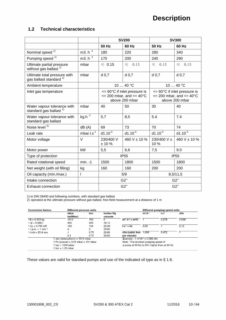
1.2 Technical characteristics SV200 SV300
50 Hz 60 Hz 50 Hz 60 Hz
Nominal speed 1) m3. h -1 180 220 280 340
Pumping speed 1) m3. h -1 170 200 240 290
Ultimate partial pressure without gas ballast 1)
mbar ≤ 0.15 ≤ 0.15 ≤ 0.15 ≤ 0.15
Ultimate total pressure with gas ballast standard 1)
mbar d 0,7 d 0,7 d 0,7 d 0,7
Ambient temperature 10 … 40 °C 10 … 40 °C
Inlet gas temperature <= 60°C if inlet pressure is <= 200 mbar, and <= 40°C
above 200 mbar
<= 60°C if inlet pressure is <= 200 mbar, and <= 40°C
above 200 mbar
Water vapour tolerance with standard gas ballast 1)
mbar 40 50 30 40
Water vapour tolerance with standard gas ballast
kg.h -1 5,7 8,5 5.4 7.4
Noise level 2) dB (A) 69 73 70 74
Leak rate mbar.l.s-1 d1.10-3 d1.10-3 d1.10-3 d1.10-3
Motor voltage V 230/400 V ± 10 %
460 V ± 10 % 230/400 V ± 10 %
460 V ± 10 %
Motor power kW 5,5 6,6 7,5 9.0
Type of protection IP55 IP55
Rated rotational speed min. -1 1500 1800 1500 1800
Net weight (with oil filling) kg 160 160 200 200
Oil capacity (min./max.) l 5/9 8,5/11,5
Intake connection G2’’ G2’’
Exhaust connection G2’’ G2’’
1) to DIN 28400 and following numbers, with standard gas ballast 2) operated at the ultimate pressure without gas ballast, free-field measurement at a distance of 1 m
These values are valid for standard pumps and use of the indicated oil type as in § 1.8.
Description

130001808_002_C0 SV200 & 300 ATEX Cat 2 11/2016 11 / 64
Dimensional drawing SV300 air cooled
Fig 1.1
Description

130001808_002_C0 SV200 & 300 ATEX Cat 2 11/2016 12 / 64
Dimensional drawing SV200 air cooled
Fig 1.3
Description

130001808_002_C0 SV200 & 300 ATEX Cat 2 11/2016 13 / 64
Pumping speed curves
Description
130001808_002_C0 SV200 & 300 ATEX Cat 2 11/2016 14 / 64
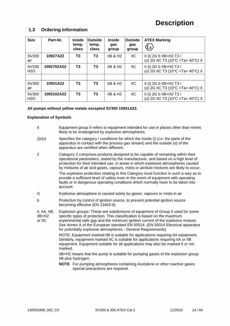
1.3 Ordering Information Size Part-Nr. Inside
temp. class
Outside temp. class
Inside gas
group
Outside gas
group
ATEX Marking
SV200 air
10927A22 T3 T3 IIB & H2 IIC II (i) 2G b IIB+H2 T3 / (o) 2G IIC T3 (10°C <Ta< 40°C) X
SV200 H2O
1092702A22 T3 T3 IIB & H2 IIC II (i) 2G b IIB+H2 T3 / (o) 2G IIC T3 (10°C <Ta< 40°C) X
SV300 air
10931A22 T3 T3 IIB & H2 IIC II (i) 2G b IIB+H2 T3 / (o) 2G IIC T3 (10°C <Ta< 40°C) X
SV300 H2O
1093102A22 T3 T3 IIB & H2 IIC II (i) 2G b IIB+H2 T3 / (o) 2G IIC T3 (10°C <Ta< 40°C) X
All pumps without yellow metals excepted SV300 10931A22. Explanation of Symbols
II Equipment group II refers to equipment intended for use in places other than mines likely to be endangered by explosive atmospheres.
(i)/(o) Specifies the category / conditions for which the inside (i) (i.e. the parts of the apparatus in contact with the process gas stream) and the outside (o) of the apparatus are certified when different.
2 Category 2 comprises products designed to be capable of remaining within their operational parameters, stated by the manufacturer, and based on a high level of protection for their intended use, in areas in which explosive atmospheres caused by mixtures of air and gases, vapours, mists or air/dust mixtures are likely to occur. The explosion protection relating to this Category must function in such a way as to provide a sufficient level of safety even in the event of equipment with operating faults or in dangerous operating conditions which normally have to be taken into account.
G Explosive atmosphere is caused solely by gases, vapours or mists in air
b Protection by control of ignition source, to prevent potential ignition source becoming effective (EN 13463-6).
II, IIA, IIB, IIB+H2 or IIC
Explosion groups: These are subdivisions of equipment of Group II used for some specific types of protection. This classification is based on the maximum experimental safe gap and the minimum ignition current of the explosive mixture. See Annex A of the European standard EN 50014. (EN 50014 Electrical apparatus for potentially explosive atmospheres - General Requirements) NOTE: Equipment marked IIB is suitable for applications requiring IIA equipment. Similarly, equipment marked IIC is suitable for applications requiring IIA or IIB equipment. Equipment suitable for all applications may also be marked II or not marked. IIB+H2 means that the pump is suitable for pumping gases of the explosion group IIB plus hydrogen. NOTE For pumping atmospheres containing Acetylene or other reactive gases
special precautions are required.
Description

130001808_002_C0 SV200 & 300 ATEX Cat 2 11/2016 15 / 64
T3 Temperature Class: Classification of equipment into classes depending on their maximum surface temperature according to the following table:
Temperature class Maximum surface temperature (°C)
T1 450
T2 300
T3 200
T4 135
T5 100
T6 85
Gases and vapours used with these pumps should have an ignition temperature greater than 200°C.
NOTE. The Temperature Class and the actual maximum surface temperature of the equipment includes the safety margin to the minimum ignition temperature of the potentially explosive atmosphere as required in EN 1127-1
Ta Allowable ambient temperature for use of the pump 10°C< Ta < 40°C
X Special operating conditions for safe use apply - see information given in this manual
Description

130001808_002_C0 SV200 & 300 ATEX Cat 2 11/2016 16 / 64
Connections Pump SV200 air cooled SV200 water
cooled SV300 air cooled SV300 water
cooled
Pump 10927A22 1092702A22 10931A22 1093102A22
Intake connection G2”
Exhaust connection
G2”
Rubber feet connection
M10 female thread
Gas ballast connection
Air filter or DN 16 ISO-KF see § 4.1.
Gas ballast type Manual, other types available upon request in specific P/N
Anti suck back valve
Standard, spring operated
Mains voltage 5.5 kW @ 50 Hz 230/400 V ± 10 %, 50 Hz 460 V ± 10 %, 60 Hz
7.5 kW @ 50 Hz 230/400 V ± 10 %, 50 Hz 460 V ± 10 %, 60 Hz
PTC thermistors Wires in motor connection box
Oil type LVO 210
Water temp --- 5 - 25 °C --- 5 - 25 °C
Water flow --- 600 l/h --- 600 l/h
Water pressure --- 2 to 8 bar --- 2 to 8 bar
Thermostatic valve setting
--- 1 --- 1
Water quality --- 4 – 8 TH (°F) --- 4 – 8 TH (°F)
Carbonate content
--- 30 – 80 ppm --- 30 – 80 ppm
PH --- 5 – 7.5 --- 5 – 7.5
Connections --- Barbed fitting for 16 mm inner diameter hose
--- Barbed fitting for 16 mm inner diameter hose
PT 100 connection See specification at the end of the document.
Oil level switch connection
See specification at the end of the document. NAMUR output.
Oil casing pressure transmitter connection
See specification at the end of the document. 4 – 20 mA output.
Motor connection 1 cable gland M25 for power cable. - Non-screened cable outer diam. 13 to 15.5 mm - Screened cable outer diam. 19 to 24 mm 1 cable gland M20 for PTC thermistors cable. - Non-screened cable outer diam. 5.5 to 8 mm - Screened cable outer diam. 10 to 15 mm See specification at the end of the document.
Description

130001808_002_C0 SV200 & 300 ATEX Cat 2 11/2016 17 / 64
Attention: Thermostatic valve setting on water cooled pumps must not be modified !
Warning
1.4 Connection fittings pump intake
Item Description Part-Nr.
1 Union coupling + seal 711 18 025
2 Nipple 711 18 035
14 Elbow 90° 711 18 215
15 Dust filter with polyester cartridge
9714 57 140
Replacement polyester cartridge
971 457 200
Only these above listed elements are allowed on ATEX CAT 2 pumps. All elements must be properly grounded or it must be checked that the earthing continuity to the pump grounding is granted. For carrying out the earthing continuity test, please refer to § 5.4.D.
Warning
1.5 Connection fittings pump gas ballast Item Description Part-Nr.
14 Centering ring 16 KF 710 39 843
15 O-ring for centering ring 239 70 176
16 Clamp for 16 KF 183 41
17 Adapter 16 KF G ½ F 714 08 741
18 Filter with clamp (Item 22) 9714 42 250
23 Grounding cable E6507946
Description

130001808_002_C0 SV200 & 300 ATEX Cat 2 11/2016 18 / 64
1.6 Accessories Description Part-Nr.
Oil drain tap 711 30 114
Gas ballast big flow (10%) KIT Upon request
Adapter Roots 500 953 90
Adapter Roots 1000 953 91
Pump base frame 711 19 208
Base frame for Roots direct mounting 711 19 209
Stability of pump is insured with accessories of Leybold; mounting of any other accessory will engage the responsibility of user concerning stability of pump.
Caution
1.7 SV + Roots combinations
In case a direct Roots pump coupling is used, it is important to check the gas temperature due to the Roots compression. Only these above listed elements are allowed on ATEX CAT 2 pumps. All elements must be properly grounded or it must be checked that the earthing continuity to the pump grounding is granted. For carrying out the earthing continuity test, please refer to § 5.4.D.
Warning
Description

130001808_002_C0 SV200 & 300 ATEX Cat 2 11/2016 19 / 64
1.8 Spare parts Description P/N SV 200 P/N SV 300
Exhaust filter 971438680 971432040
Maintenance kit 971463430 971463140
Repair kit 971463440 971463150
Pipe kit 971463400 971463080
Generator kit 971463380 971463010
Polyester inlet filter element 971457200
Gas ballast inlet filter 971442250 Only original Leybold parts are be used in the pumps. A non respect of this will entail a loss of the pump’s ATEX certification.
Warning
1.9 Lubricants
The Leybold LVO 210 oil is a diester oil particularly suited for the SV200 / 300 ATEX pumps. Only original Leybold LVO 210 oil is to be used in the pumps. A non respect of this will entail a loss of the pump’s ATEX certification.
Warning
Oil volume Part-Nr.
2 l 9714 30 531 / L21002
5 l 200 10 891 / L21005
20 l 200 00 193 / L21020
200 l 200 03 257 / L21099
Description
130001808_002_C0 SV200 & 300 ATEX Cat 2 11/2016 20 / 64
2 Transport and Storing 2.1 Transport and packaging SOGEVAC®
vacuum pumps pass a rigorous operating test in our factory and are packaged to avoid transport damages. Please check packaging on delivery for transport damages. Packing materials should be disposed off according to environmental laws or re-cycled. These operating instructions are part of the consignment. The connection ports are blanked off by plastic protective caps or stickers. Take these caps or self-adhesives away before turning on the pump. The pumps have the LVO 210 oil filled in.
2.2 Mounting orientation
See required space on drawings in paragraph 1.2. Pumps which have been filled with oil must only be moved in the upright position (horizontally). Otherwise oil may escape. The angle of slope may not be over 10° max. Avoid any other orientations while moving the pump. Check the pump for the presence of any oil leaks, because there is the danger that someone may slip on the oil which has leaked from the pump. Only use the lifting lugs which are provided on the pump to lift the pump with the specified lifting devices. Make sure that these have been installed safety. Use suitable lifting equipment. Make sure that all safety regulations are observed. Use only lifting devices appropriated to the pump weight. Check name plate. Do not use other pump elements than the lifting lugs as handles.
Caution
2.3 Storage
Before stocking the pump for a long time put it back in its original condition (blank off inlet and exhaust ports with the shipping seals, drain the oil) and store the pump in a dry place at room temperature. Until the pump is put back in to service again, the pump should be stored in a dry place, preferably at room temperature (20 °C - 168 °F). Before taking the pump out of service, it should be properly disconnected from the vacuum system, purged with dry nitrogen and the oil should be exchange too. The inlet and exhaust ports of the pump must be blanked off using the shipping seals which are included upon delivery of the pump. Drain the water from the cooling circuit (See § 3.2). The gas ballast must be closed and if the pump is to be shelved for a longer period of time is should be sealed in a plastic bag together with a desiccant (Silicagel). If the pump has been shelved for over one year, standard maintenance must be done and the oil must be exchanged too before the pump is put in to service once more. We recommend that you contact the service from Leybold.
Caution
Transport and Storing

130001808_002_C0 SV200 & 300 ATEX Cat 2 11/2016 21 / 64
3 Installation It is essential to observe the following instructions step by step to ensure safe start-up. Start-up may only be conducted by trained ATEX specialists. Before installing the pump you must reliably disconnect it from the electrical power supply and prevent the pump form running up inadvertently. Observe all safety regulations. The pump is only ATEX if it is controlled by a suitable control system, if all sensors and switches are connected & integrated into the controls algorithms. Furthermore, we recommend that a pilot valve is installed on the pump inlet to allow a pump warming before the process start & oil degassing after the process. The valve is not part of the pump scope of delivery. Please note that the gas temperature must be measured. Do not stand on the pump and do not place objects on the pump as these can cause deformation of the fan housing and possible frictional rubbing.
Warning
3.1 Installation
The SOGEVAC® can be set up on any flat, horizontal surface. Under the four feet, there are metric threaded holes (M10) for securing the pump. The oil level cannot be read properly if the pump is tilted and lubrication may be affected. The max. slope angle is ± 1°. The pump’s ambient temperature must be between 12°C (55°F) and 40°C (104°F). To ensure adequate cooling of the pump, leave enough space at the air intake and exhaust points, and for access and maintenance (see Fig. 1.1 to 1.4) Make sure to keep the cooling coils & air intake of the motor clean. The pump is to be installed such that the oil level sight-glass can be both easily read and so that it will not be broken.
Warning
3.2 Connection to the system
Intake Side Pump should be connected to inlet line without any tension. Use flex lines or pipe unions in your inlet and exhaust lines so that they can be easily removed for pump maintenance. The maximum pressure at the inlet may not exceed atmospheric pressure (about 1013 mbar). Never operate the pump in the presence of over pressures at its intake. Type of materials used for mounting of pipings should take care of pumped gases & ATEX regulations. It is the same for its tightness. Using suitable connecting elements (see § 1.4) the pump can be connected to the vacuum system. The cross-section of the intake line should be at least the same as the one for the intake port. If the intake line is too narrow, it reduces the pumping speed. If the process gas contains dust, it is absolutely essential to install a dust filter in addition to the dirt trap supplied (see §1.4). We recommend installing the dust filter horizontally. This ensures that when removing the filter no particles fall into the intake port. When pumping vapours, we recommend installing condensate traps on the intake and exhaust sides. The intake must be installed in such a way to avoid condensates flowing into the pump.
Caution
Installation

130001808_002_C0 SV200 & 300 ATEX Cat 2 11/2016 22 / 64
Exhaust Side The SOGEVAC® pumps have integrated exhaust filters which, even at a high gas throughput, trap the oil mist and guarantee exhaust gas free of oil mist. If the exhaust filters are clogged, the by pass opens at 1.5 bar, (absolute pressure), and the filters are bypassed. As a result, the proportion of oil in the exhaust gas as well as the pump’s oil consumption will rise. Installing new exhaust filters will correct this problem. (See § 5.4.D). Check in the individual case whether a line is necessary and/or prescribed. Volatile substances will pass through the filter. Depending on the process gas, we recommend connecting an exhaust line; this is always necessary when the exhaust gases are dangerous. The maximum exhaust pressure must neither exceed 1.15 bar absolute (0.15 bar relative), nor fall under atmosphere pressure minus 15 mbar. The cross-section of the exhaust line should be at least the same as the pump’s exhaust port. If the exhaust line is too narrow, overpressure or overheating may occur in the pump. Before installing the exhaust line, remove the exhaust-flange plate and ensure that the exhaust demister(s) are secured tightly in place. They sometimes loosen during shipping and installation. A loose demister results in exhaust smoke during start-up and operation. Install the exhaust line with a downward slope to prevent condensate from flowing back into the pump. If this is not possible, we strongly recommend installing a condensate trap. Never operate the pump with a blocked or restricted exhaust line. Before start-up, ensure that any blinds or similar shut-off devices in the exhaust line on the pressure side are opened and that the exhaust line is not obstructed. Exhaust pipe material must be resistant to pumped gases.
Caution Warning
Any pump or accessory modification and the use of non Leybold approved pump condition sensors are prohibited without our written consent. Otherwise, the CE Declaration & ATEX certification become void.
Warning
Installation

130001808_002_C0 SV200 & 300 ATEX Cat 2 11/2016 23 / 64
Water cooling Depending of the P/N, the SOGEVAC® pumps are equipped with a water cooling system and a thermostatic valve. Depending on the local regulations, the cooling water needed may not be taken from the drinking water mains and max. water temperatures must be observed. The water cooling connection is made by barbed fitting for 16 mm inner diameter hose adapters. The thermostatic valve regulates the cooling water throughput, and so the pump temperature. The valve is set in standard on position 1. Thermostat setting must be left on position 1 (valve fully open). Do not use deionised cooling water. To clean the heat exchanger: it is recommended to clean at least twice a year the water circuit. For that, dismantle the exchanger from the pump. Chemical cleaning is the most efficient, with dilute hydrochloric acid solution (5 to 10%) then neutralize with hexamethylethyrene tetramine at 0.2 %. For a 1 mm coat of scale, leave acting the acid during about 30 min. The system must be open during the operations, so the product gases can escape. Rinse copiously with water after neutralization. Proceed in an open and well ventilated place. Observe the safety regulations given by the manufacturer of the product you are using. Observe the regulations for the treatment and the disposal of chemical products. Observe the relevant environmental regulations. Draining of the water-cooling circuit (before transport, long time storage, winter time). Place a water recovery pan under the heat exchanger and unscrew the draining plug. The heat exchanger water will drain. To drain completely the heat exchanger: Remove the water outlet hose and close the water outlet with a plug. Remove the water inlet hose Connect a compressed air supply in place of water outlet port and blow. Attention, water will be evacuated through the water inlet connection. Reassemble in the reverse sequence.
Warning
Installation

130001808_002_C0 SV200 & 300 ATEX Cat 2 11/2016 24 / 64
3.3 Electrical connections Ensure that incoming power to the pump is off before wiring the motor or altering the wiring. The specific wiring and instructions for installation in potentially explosive atmospheres given in the manual for the electric motor must be followed. Additional information can be found in the European Standard EN 60079-14 Electrical apparatus for explosive gas atmospheres Part 14 Equipment for use in potentially explosive gas atmospheres and EN 60079-17 Electrical apparatus for explosive gas atmospheres Part 17. The use of frequency converters to control the SOGEVAC ATEX Cat. 2 pumps is not allowed. The pump should be adequately earthed to prevent the accumulation of static electricity. The electrical junction box should only be opened and electrical connections made when no explosive atmosphere is present.
Warning
230 V, 50 Hz 400 V, 50 Hz & 460 V, 60 Hz Electrical connection work must only be carried out by a qualified electrician in accordance with the applicable safety rules, see IEC 60204-1 & 61010-1. Connect the pump’s motor to the right supply voltage via the connections in the junction box (see fig. 6). The relevant safety rules require the use of a suitable motor protection switch. Set the switch in accordance with the rating on the motor nameplate.
If any security switch or electrical defect cuts out the pump, re-start-up of the pump has to be possible only manually. The pump is designed for direct starting even under load conditions, i.e. the pump can be switched on against vacuum in the intake port. After connecting the motor and after every time you alter the wiring, check the direction of rotation. Refer to the marking on the motor. During the check, the intake port should be open. If the direction of rotation is wrong, oil may be ejected out the intake port. (The vacuum system may be pressurised). For the check, switch on the motor briefly. If it starts up with the wrong direction of rotation, switch it off immediately and interchange two phases of the connection. It is recommendable to check the direction of rotation with a phase sequence indicator. Prolonged running of the motor in the wrong direction of rotation will damage the pump ! Motor protection device
Installation
Installation

130001808_002_C0 SV200 & 300 ATEX Cat 2 11/2016 25 / 64
To protect the motor windings against a variety of operational malfunctions, the motor is fitted with protection device, which must be connected. PTC thermistors acc. to IEC 60034-1 and DIN 44081/440823 are temperature dependent, semi-conductor devices embedded in the motor windings. Temperature Sensor PT100 A temperature sensor type PT100 is placed on the vacuum generator close to the exhaust valves. The temperature sensor monitors the pump temperature. The PT100 manual is attached at the end of the instruction manual. See next page for threshold values. Oil level Switch The manual is attached at the end of the instruction manual. The pump must be switched off and the pump and oil level checked immediately if the oil level is too low. To avoid false alarms it is recommended to use a timer of 20 seconds on the switch output. If the default remains longer than 20 seconds, the pump must be switched off. Over pressure sensor The manual is attached at the end of the instruction manual. The pump must be switched off and the pump, exhaust line and exhaust filters checked immediately if the pressure in the oil casing is too high. The sensor delivers a 4 – 20 mA signal. See next page for threshold values. Associated Electrical equipment The electrical equipment supplied with this pump e.g. motor, valves, sensors etc. are also suitable for use in potentially explosive gas / dust atmospheres under the same conditions as those for the pump. The instructions given in the electrical motor manufacturer's Information for Use attached to this manual must be complied with. The electrical motor and accessories meet the IP65 enclosure requirements or their equivalent. The ignition protection sensors (over-temperature, outlet-pressure, oil-level) must be used to protect the pump against critical operational parameters and must be configured to cause shut of the pump if the values go outside of the allowable range. Additionally the Temperature and pressure measurements should be configured to be fail safe i.e. loss of signal from the sensor should cause the pump to shut down. Restart should not be possible without re-setting of the ignition preventing system. The system should meet requirements of IPL1 (EN13463-6) equivalent to SIL1 (EN 61508) or EN 954-1.

130001808_002_C0 SV200 & 300 ATEX Cat 2 11/2016 26 / 64
Pump System Overview

130001808_002_C0 SV200 & 300 ATEX Cat 2 11/2016 27 / 64
Decision Diagram
°C 0 10 20 30 40
0 100 103,9 107,79 111,67 115,54
100 138,51 142,29 146,07 149,83 153,58
°C 50 60 70 80 90
0 119,4 123 ,24 127,08 130,9 134,71
PT100 resistance table
or PI2 > p atm + 50 mbar or PTC switching

130001808_002_C0 SV200 & 300 ATEX Cat 2 11/2016 28 / 64
Wiring diagram

130001808_002_C0 SV200 & 300 ATEX Cat 2 11/2016 29 / 64
Example of electrical diagram

130001808_002_C0 SV200 & 300 ATEX Cat 2 11/2016 30 / 64
Example of electrical diagram

130001808_002_C0 SV200 & 300 ATEX Cat 2 11/2016 31 / 64
3.4 Start-up
Control Parameters for the Ignition Prevention System Temperature
Sensor PT100 Oil Casing Pressure Sensor
Oil Level Sensor
Alarm Value 105 °C (140.38 Ohm)
500 mbar rel. (7.2 mA)
N/A
Pump Stop Value and Timer
115 °C (144.16 Ohm) Immediately
650 mbar rel.* (8.16 mA). After 15 s
or 1000 mbar rel.*
(10.4 mA). Immediately
At switching to low level. After 20 s
Accuracy + 1 °C + 15 mbar N/A *During cold start up the pressure in the oil casing can rise momentarily to above 650 mbar due to the oil filters being temporally blocked by oil. In order to prevent an inadvertent shut-off of the pump the pressure sensor control system should include a delay such that the pressure must be above 650 mbar for 15 s before the pump is switched off. If the pressure in the oil casing rises above 1 bar overpressure the pump should be immediately switched off as this indicated that the outlet is blocked.
Caution
The oil for the first filling is supplied with the pump. Before switching on, always make sure that the pump contains enough oil. The normal oil level is in the middle of sight glass. If oil has to be added, unscrew the oil-fill plug, add oil and screw the plug firmly back in. The SOGEVAC® is designed for normal start-up at temperatures over 12°C (54°F) (as per PNEUROP). The used oils allow pump start above 0°C (32°F).
Caution
Before starting the pump ensure that the attached accessories meet the requirements of your application and that safe operation is ensured. Never expose part of the body to the vacuum. Do not lay the hand on the intake to check suction. Exposure of a part of the body to the vacuum result in a rush of blood in the exposed part. There is a danger of injury. Never operate the pump with an open and thus accessible inlet. Vacuum connections as well as oil filling and oil draining openings must not be opened during operation of the pump. The safety regulations which apply to the specific application in each case must be observed. This applies in particular to installation, operation and maintenance (servicing) as well as waste disposal and transportation.
Warning
Installation

130001808_002_C0 SV200 & 300 ATEX Cat 2 11/2016 32 / 64
4 Operation 4.1 Operation To avoid overloading the motor, do not start the pump more than six times within one hour. If frequent starts are needed, the pump shall run continuously and be linked to the vacuum vessel by means of a valve. In that case, regulation will be made by the valve and not by start/stop of the pump. With the valve closed, the pump consumes little energy. The SOGEVAC® can pump gases and vapours, provided that the gas ballast valve is installed and open and the pump has reached its operating temperature. Pump in function is hot and some surfaces could reach a temperature higher than 80°C (176°F). There is a risk of burn by touching. Take note of warning labels on the pump.
Warning
Pumping of non-condensable gases If the pump system contains mainly non condensable gases, the pump should be operated without gas ballast. If the composition of the gases to be pumped is not known and if condensation in the pump cannot be ruled out, run the pump with gas ballast valve open in accordance with section below. Pumping of condensable gases and vapours If ATEX gases are pumped, it is mandatory to use an inert GB gas supply through the DN16 KF connection. The GB air filter is to be used only if no ATEX gases are pumped. With the gas ballast valve open and at operating temperature, the SOGEVAC® can pump pure water vapour up to the values indicated in the Technical Data. The gas ballast valve is opened by a screwdriver. The running noise of the pump is slightly louder if the gas ballast valve is open. Before pumping vapours ensure that the pump has warmed up for approx. 30 min. with closed intake line and with open gas ballast valve.
Don’t open the pump to condensable vapours until it has warmed to operating temperature: pumping process gas with a cold pump results in vapours condensing in the oil. For processes with a high proportion of condensable vapours, the intake line should be opened only slowly after reaching the operating temperature. One sign of condensation of vapours in the pump is a rise of the oil level during operation of the pump.
Caution
When vapours are pumped, the pump must not be switched off immediately after completion of the process because the condensate dissolved in the pump oil may cause changes or corrosion. To prevent this, the pump must continue to operate with open gas ballast valve and closed intake port until the oil is free of condensate. We recommend operating the pump in this mode for at least 30 min. after completion of the process. In cycle operation, the pump should not be switched off between the cycles but should continue to run with gas ballast valve open and intake port closed (if possible via a valve). Power consumption is minimal when the pump is operating at ultimate pressure. Once all vapours have been pumped off from a process (e. g. during drying), the gas ballast valve can be closed in order to improve the ultimate pressure.
Caution
Operation

130001808_002_C0 SV200 & 300 ATEX Cat 2 11/2016 33 / 64
The SOGEVAC® SV200 and SV300 can be equipped with different types of gas ballasts, as defined by their cat-nr. Changing the type of GB can change the ATEX temperature class ! Consult us before any GB retrofit is undertaken ! Such a modification must be done by Leybold Service only, and the pump will bear a new P/N. The GB flow is valid for a pump operating at ultimate pressure (inlet closed) and for a GB gas supply of max. 1 bar abs. Standard gas ballast (flow approx. 7.5 Nm3/h) This gas ballast corresponds to the most important part of applications. Gas ballast "Big Flow" (flow approx. 18 Nm3/h) This kit is intended for the applications where more vapours of condensable gases could come into the pump. It brings the water vapour tolerance above 50 mbar. Changing the type of GB can change the ATEX temperature class ! Consult us before any GB retrofit is undertaken ! Such a modification must be done by Leybold Service only, and the pump will bear a new P/N. On application where vapours are always present, the use of a permanent GB is recommended. In this case a lower ATEX temperature class can be reached. All gas-ballasts are to be connected either through the air-filter or through a DN 16 ISO-KF connection to an inert gas supply. If gas supply piping and valves are fitted to the gas ballast it must be ensured that a continuous flow of gas through the gas ballast is present when the pump gas ballast valve is open (for example by use of a suitable flow meter or suitable pressure measurement). This is to ensure that no adiabatic compression occurs in the gas ballast pipe which could lead to a high temperature. Gas supply for gas ballast must come from safe area.
Warning
Do not open the pump to condensable vapours until it has warmed to operating temperature; pumping process gas with a cold pump results in vapours condensing in the oil. For processes with a high proportion of condensable vapours, slowly open the intake line, after reaching the operating temperature to prevent excessive quantities of vapour entering the pump. One sign of condensation of vapours in the pump is a rise in the oil level during operation of the pump. During pumping, vapours may dissolve in the oil. This changes the oil properties and causes a risk of corrosion in the pump. Therefore, do not switch off the pump immediately after completion of the process. Instead, allow the pump to continue operating with the gas ballast valve open and the intake line closed until the oil is free of condensed vapours. We strongly recommend operating the pump in this mode for about 30 minutes after completion of the process. In cyclic process operation, the pump should not be switched off during the intervals between the individual working phases, but should continue to run with gas ballast valve open and intake port closed (if possible via a valve). Power consumption is minimal when the pump is operating at ultimate pressure. Once all vapours have been pumped off from a process (e.g. during drying), the gas ballast valve can be closed to improve the ultimate pressure. Wear ear protection if the pump operates at high inlet pressure !
Warning
Operation

130001808_002_C0 SV200 & 300 ATEX Cat 2 11/2016 34 / 64
4.2 Shutdown Under normal circumstances, all that you need do is to switch off the pump. The intake port of the SOGEVAC® contains an anti-suck back valve, which closes the intake port when the pump is shut down, to avoid the pump oil being sucked back into the vacuum chamber. The valve's functioning is not impaired by gas ballasting. The anti-suck back valve is not a safety vacuum valve. When pumping condensable media, let the pump continue to operate with the gas ballast valve open and the intake line closed before switching off. If the pump is to be shut down for an extended period or if the pump has to be stored, proceed as follows: When pumping harmful substances, take adequate safety precautions. Drain the oil (see Section 5.4). Pour in clean oil up to the bottom edge of the oil-level glass (see Section 5.4) and let the pump run for a few minutes. Then drain the oil and pour in clean oil up to the top edge of the oil-level glass (see Section 5.4). Seal the connection ports. Special preservation or flushing oils are not necessary. When the pump has been switched off due to over-heating, initiated by the motor or its protection, the pump must be cooled down to the ambient temperature and must only be switched on again manually after having eliminated the cause. In order to prevent the pump from running up unexpectedly after a mains power failure, the pump must be integrated into the control system in such a way that the pump can only be started by a manually operated switch. This applies equally to emergency cut-off switches. In case of switching processes in connection with a pump which has warmed up under operating conditions, the pump must then not be directly switched on again.
Warning
Warning
4.3 Ultimate pump pressure If the system cannot produce the pressures specified in the technical date, measure the ultimate pressure directly at the pump's intake port after disconnecting the pump from the system. The ultimate pressure of non-condensable gases (partial pressure of air) can only be measured with a compression vacuum gauge or a partial pressure gauge. Precise measurements can only be obtained with calibrated instruments. Upon initial start-up, after prolonged idle periods or after an oil change, it takes a while until the pump reaches the specified ultimate pressure. The pump has to attain its operating temperature, and the pump oil has to be degassed. We recommend operating the pump initially with the gas ballast valve open. The ultimate pressure depends on the pump temperature and the pump oil used. The best ultimate pressures can be obtained at a low pump temperature and by using the recommended oil types.
Operation

130001808_002_C0 SV200 & 300 ATEX Cat 2 11/2016 35 / 64
5 Maintenance 5.1 Safety Information Observe all safety regulations. All work must be done by suitably trained ATEX personnel. Maintenance or repairs carried out incorrectly will affect the life and performance of the pump, may change its ATEX ratings and may cause problems when filing warranty claims or free Leybold from any responsibility. Before any maintenance operations are carried out on the pump it should be ensured that the pump and its surroundings are free from flammable atmospheres and dust deposits. Where dust can be deposited on the pump or motor surfaces, provision should be made to ensure that these are removed regularly. The pump must remain clean & dust-free. The cleaning must be done with cloths / products avoiding static charges. Never mount used seals; always mount new seals. Only the use of genuine Leybold parts is allowed ! Any integration of non Leybold parts or non authorized repairs will cancel the pump ATEX certification and will waive all Leybold ATEX responsibilities. Disconnect the power before disassembling the pump. Make absolutely sure that the pump cannot be accidentally started. If the pump has pumped harmful substances, ascertain the nature of the hazard and take adequate safety measures. Observe all safety regulations.
Warning
The equipment must be maintained in such as way that the safety of the system is not impaired in any way. A detailed ATEX inspection scheme is applied to all ATEX pumps repaired by Leybold, it involves inspecting all flame paths and ensuring the correct assembly of the product. The system instruction manual details the routine maintenance tasks that are necessary to maintain ATEX compliance. Where the customer wishes to conduct more complex maintenance / overhaul tasks it is necessary for them to be trained by Leybold and supplied with the correct maintenance / inspection tooling. If a customer conducts this work without the correct training, the ATEX certification will be invalid. Spare parts: ATEX certified components must be replaced with compatible components having the same level of ATEX certification. They will under go an ATEX component inspection by Leybold at the point of build into an ATEX certified pump. Components supplied directly to customers cannot be pre-inspected due to the potential for damage prior to build. Where a customer buy a service module with the intention of creating an ATEX approved pumping package, it becomes their responsibility to full fill their duties under the ATEX directives. Leybold is not in a position to assist customers to achieve their own third party ATEX approval. The serial number of re-manufactured modules will be retained on a service database in order to ensure traceability. In addition to the maintenance operations given in the manual, a complete overhaul of the pump including the replacement of the bearings should be carried out every 15’000 h of operation or every 3 years which ever is the sooner.
Maintenance

130001808_002_C0 SV200 & 300 ATEX Cat 2 11/2016 36 / 64
5.2 Maintenance Intervals The intervals stated in the maintenance schedule are approximate values for normal pump operation. Unfavourable ambient conditions and/or aggressive media may significantly reduce the maintenance intervals.
Warning
Maintenance job Frequency Section Checking the oil level Daily. 5.4.A Checking the oil condition Depends of process, at least weekly. 5.4.B First oil change After 150 hours of operation. 5.4.C Following oil changes Depends of process. 5.4.C Changing the exhaust filters If oil mist at exhaust or at indication of exhaust filter
pressure sensor. At least annually. 5.4.D
Checking the float valve At each exhaust filter change or at least yearly. 5.4.E Cleaning the intake port dirt trap Depends of process, at least monthly. 5.4.F Checking the anti suck back valve
Depends of process, at least yearly. 5.4.F
Cleaning the gas ballast air filter Depends of ambient air quality, at least monthly. 5.4.G Cooling coil cleaning Depends of ambient conditions, at least yearly. 5.4.H Water cooling heat exchanger cleaning
Depends of cooling water quality, at every 6 months.
5.4.I
Replacing the Exhaust Valves In case of specific pump servicing. 5.4.J Replacing the Pump Module In case of specific pump servicing. 5.4.K Replacement of electrical motor In case of specific pump servicing. 5.4.L Procedure for Checking the Ignition Prevention System
At every maintenance operation or at least once a year.
5.4.M
To simplify the maintenance work we recommend combining several jobs.
Maintenance

130001808_002_C0 SV200 & 300 ATEX Cat 2 11/2016 37 / 64
5.3 Service at Leybold facilities If you send a pump to us, indicate whether the pump is free of substances damaging to health or whether it is contaminated. If it is contaminated also indicate the nature of hazard. For this you must use the form we have prepared and which will be provided upon request. A copy of this form, "Declaration of Contamination of Vacuum Instruments and Components" is reproduced at the end of the Operating Instructions. Another suitable form is available from www.leybold.com ’ Documentation ’ Download Documents. Please attach this form to the pump, or enclose it with it. This statement detailing the type of contamination is required to satisfy legal requirements and for the protection of our employees. We will return any pump received without a "Declaration of Contamination" to the sender's address. The pump must be packaged in such a way that it will not be damaged during shipping, and so that no harmful substances can escape from the package. If you open a pump at your own works also observe a potential contamination. When disposing of used oil, please observe the relevant environmental regulations. Due to the design concept, SOGEVAC® pumps require very little maintenance under normal operating conditions. The work required is described in the sections below. All work must be done by suitably trained personnel. Maintenance or repairs carried out incorrectly will affect the life and performance of the pump and may cause problems when filing warranty claims. Also incorrect maintenance can cause a pump temperature increase, which can influence the pump ATEX temperature rating !
Warning
Warning
In connection with this, you may be interested in the Leybold practical seminars, in which maintenance, repair and testing information for the Sogevac® pumps is conveyed by qualified trainers. In addition to the technical seminars, we recommend our additional ATEX seminar that covers the ATEX basics as well as ATEX topics concerning the Sogevac® pumps. Information on these seminars will be mailed to you upon request.
Maintenance

130001808_002_C0 SV200 & 300 ATEX Cat 2 11/2016 38 / 64
5.4 Maintenance Work 5.4.A Checking the oil level The pump’s oil level during operation must always be between the middle and top edge of the oil-level glass. When necessary, switch off the pump and add the correct quantity of oil. Overfilling leads to oil losses at high intake pressures High oil consumption often indicates that exhaust filters are clogged (See 5.4.D). The oil level should be checked at least once a day. Stop the pump for filling oil.
5.4.B Checking the oil condition Normally the oil is clear and transparent. If the oil darkens, it is an indication that the oil must be checked. The oil must be changed if: - Its viscosity increases by 20 % compared to new oil. - Its Total Acid Index exceeds given limits, depending of oil type. Please consult us. If gases or liquids dissolved in the oil result in deterioration of the ultimate pressure, the oil can be degassed by letting the pump running for about 30 min. with the intake port closed and the gas ballast valve open. The amount of oil required for an oil check should be drained via the oil-drain plug into a beaker or similar container with the pump switched off but still at operating temperature. Bad oil quality can cause a pump temperature increase, which can influence the pump ATEX temperature rating ! Depending on the process involved, dangerous substances may escape from the pump and oil. Take the appropriate precautions. Observe the safety regulations. Check to be carried out, depending of process, at least weekly.
Warning
Maintenance

130001808_002_C0 SV200 & 300 ATEX Cat 2 11/2016 39 / 64
5.4.C Oil change Tool required : oil filter key (710 73 532) Always change the oil when the pump is switched off but still at working temperature. If there is a risk of the oil being polymerized by the connected process, change the oil immediately after operation of the pump. Pump in function is hot and some surfaces could reach a temperature higher than 80 °C (176 °F). There is a risk of burn by touching. Unscrew the oil-drain plug and let the used oil drain into a suitable container. Depending on the process involved, dangerous substances may escape from the pump and oil. Take the appropriate precautions. Observe the safety regulations. When disposing of used oil please observe the relevant environmental regulations! When the flow of oil slows down screw the oil drain plug back in, briefly switch on the pump (max. 10s) and switch if off. Remove the oil drain plug again and drain the remaining oil. Unscrew the oil-fill plug and fill the pump should be flushed by filling it with fresh oil up to the bottom edge of the oil-level glass, run it for a short time and then change the oil again. Use suitable oil only (see Section 1.9). Depending on the process involved, dangerous substances may escape from the pump and oil. Take the appropriate precautions. Never mount used seals; always mount new seals. When disposing of used oil please observe the relevant environmental regulations !
Warning
Warning
Maintenance

130001808_002_C0 SV200 & 300 ATEX Cat 2 11/2016 40 / 64
5.4.D Replacing the Exhaust Filters and Checking the Pressure Relief Valve Tools required : - Open-jaw or box wrench 19 mm, or special tool 710 72 293. - Box wrench 10 mm. When the exhaust filter elements are clogged, the over pressure (bypass) valves open and the filters are bypassed. Oil mist at the exhaust, and/or high oil consumption are signs that the exhaust filters are clogged. The over pressure sensor indicates the exhaust filter clogging state. The exhaust filters must be changed at least annually. The exhaust filters must be replaced more frequently if subjected to increased oil cracking products at high operating temperatures and/or aggressive media.
Warning
Maintenance
92
89
79 90 DETAIL A DETAIL B
91b 91a
92a
DETAIL
92b
DETAIL B

130001808_002_C0 SV200 & 300 ATEX Cat 2 11/2016 41 / 64
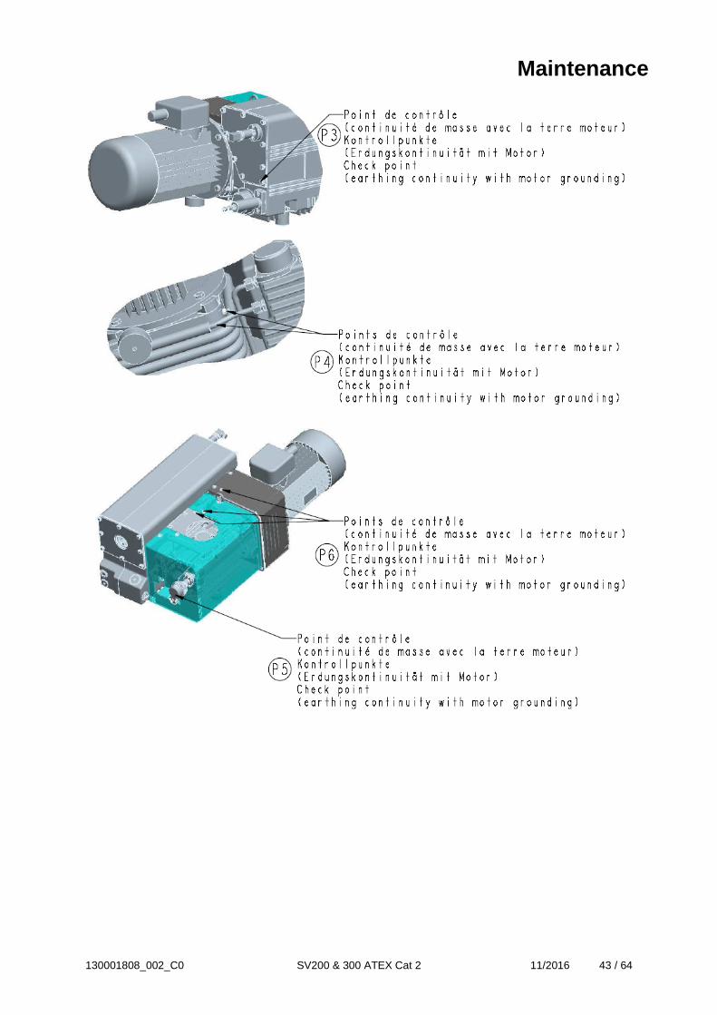
• Disassemble the exhaust filter cover pos. 89 (4 screws 79). • Unscrew nut pos.91b to remove the filter which needs to be replaced. Keep spring 91a. • Check presence of gasket, pos. 92b on new ExF. • Reassemble the ExF as shown in above drawing and make sure that the cable shoe of the earthing lid pos.92a is between the spring pos.91a and the nut 91b. • Screw the nut pos.91b until contact. • Check the earthing continuity between each ExF grid 92 and the motor grounding: the measured value shall be lower than 0,1 Ohm under a AC current of around 10 Ampere, the no-load voltage shouldn’t exceed 12 Volt. • Reassemble the flat gasket 90. • Reassemble the exhaust filter cover pos. 89 (4 screws 79) tightening torque : 15 N.m.
Depending on the process involved, dangerous substances may escape from the pump and oil. Take the appropriate precautions. Observe the safety regulations. Important When disposing of used exhaust filters please observe the relevant environmental regulations! Never mount used seals; always mount new seals.
Maintenance

130001808_002_C0 SV200 & 300 ATEX Cat 2 11/2016 42 / 64
Maintenance
130001808_002_C0 SV200 & 300 ATEX Cat 2 11/2016 43 / 64
Maintenance
130001808_002_C0 SV200 & 300 ATEX Cat 2 11/2016 44 / 64
5.4.E Checking the float valve Tools required : Open-jaw or box wrenches 10 mm, 13 mm, 17 mm. If the pressure does not fall below approx. 5 mbar during pump operation, check the tightness of the float valve and return line. Remove the fastening screws at the top of the pump-cylinder cover, loosen the pump foot at the bottom of the cover and take off the cover. Take off the oil return line. Remove the four screws and pull the float valve assembly out of the float chamber. Take off the gasket. Clean the nozzle. Check the tightness of the float valve. Check all gaskets and replace them with new ones if necessary. Reassemble the float valve in the reverse sequence. Depending on the process involved, dangerous substances may escape from the pump and oil. Take the appropriate precautions. Never mount used seals; always mount new seals. To be done at each exhaust filter change or at least yearly.
Warning
Caution
5.4.F Cleaning the intake port dirt trap and Checking the anti suck back valve Cleaning the intake port dirt trap Tools required : open-jaw or box wrenches 10 mm, 17 mm. A dirt trap for coarse particles is located in the intake flange of the pump. It shall be kept clean to avoid reduction of the pumping speed. The dirt trap consists of a wire-mesh screen. Disassemble the intake flange. To do so, remove the fastening screws at the top of the pump-cylinder cover, loosen the pump foot at the bottom of the cover and take off the cover. Remove four screws and take off the intake flange and gasket. Remove the retaining ring from inside the intake flange. Take out the wire-mesh screen and clean them using a suitable solvent. Reassemble in the reverse sequence. We recommend replacing the gasket with a new one. Depending on the process involved, dangerous substances may escape from the pump and oil. Take the appropriate precautions. Never mount used seals; always mount new seals. Depends of process, but to be done at least monthly.
Warning
Maintenance
130001808_002_C0 SV200 & 300 ATEX Cat 2 11/2016 45 / 64
Checking the Anti-Suck back Valve Tools required : - Open-jaw or box wrenches 10 mm, 17 mm. - Adjusting ring: 710 72 333 Keep the anti-suck back valve clean to ensure proper operation of the pump. In any application we strongly recommend installing an ATEX polyester dust filter upstream (see Section 1.4). First disconnect the intake line. Then remove the fastening screws at the top of the pump-cylinder cover, loosen the pump foot at the bottom of the cover and take off the cover. Remove four screws and take off the intake flange and gasket. Remove the spring and anti-suck back valve. If the anti-suck back valve closes too soon, carefully compress the spring slightly. The top edge of the valve should be about 1-2 mm away from the bottom side of the intake port. Do not screw the spring into the vacuum generator opening ! This can lead to pump destruction. Reassemble the intake port. We recommend replacing the gasket with a new one. The plane side of the anti-suck back valve faces downward. The end of the spring with the larger diameter faces down and the end with the smaller diameter faces up against the flat side of the anti suck back valve. The side of the anti-suck back valve with the rounded sealing ridge faces up. Depending on the process involved, dangerous substances may escape from the pump and oil. Take the appropriate precautions. Observe the safety regulations. Never mount used seals; always mount new seals. Depends of process, but to be done at least yearly.
Warning
Caution
Maintenance
130001808_002_C0 SV200 & 300 ATEX Cat 2 11/2016 46 / 64
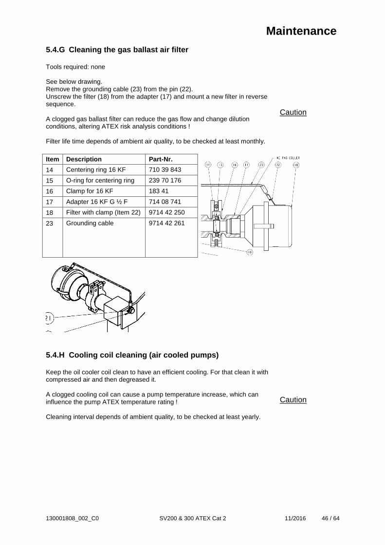
5.4.G Cleaning the gas ballast air filter Tools required: none See below drawing. Remove the grounding cable (23) from the pin (22). Unscrew the filter (18) from the adapter (17) and mount a new filter in reverse sequence. A clogged gas ballast filter can reduce the gas flow and change dilution conditions, altering ATEX risk analysis conditions ! Filter life time depends of ambient air quality, to be checked at least monthly.
Caution
Item Description Part-Nr.
14 Centering ring 16 KF 710 39 843
15 O-ring for centering ring 239 70 176
16 Clamp for 16 KF 183 41
17 Adapter 16 KF G ½ F 714 08 741
18 Filter with clamp (Item 22) 9714 42 250
23 Grounding cable 9714 42 261
5.4.H Cooling coil cleaning (air cooled pumps) Keep the oil cooler coil clean to have an efficient cooling. For that clean it with compressed air and then degreased it. A clogged cooling coil can cause a pump temperature increase, which can influence the pump ATEX temperature rating ! Cleaning interval depends of ambient quality, to be checked at least yearly.
Caution
Maintenance

130001808_002_C0 SV200 & 300 ATEX Cat 2 11/2016 47 / 64
5.4.I Water cooling heat exchanger cleaning It is recommended to clean at least twice a year the cooling water circuit. For that, dismantle the heat exchanger from the pump. Chemical cleaning is the most efficient method, using diluted hydrochloric solution (5 to 10 %) to be neutralised with hexamethilehyrenetetramine at 0,2%. For a 1 mm coat of scale, leave the acid act for about 30 minutes. The system must be open during cleaning, so that the reaction gases can escape. Rinse copiously with water after neutralisation and proceed in an open and well ventilated area. Observe the safety regulations given by the acid manufacturer. Observe the local regulations for the treatment and disposal of chemical products and the environmental regulations. A clogged heat exchanger can cause a pump temperature increase, which can influence the pump ATEX temperature rating ! Depends of cooling water quality, at least every 6 months.
Caution Warning
5.4.J Replacing the Exhaust Valves Tools required : Open-jaw or box wrenches 10 mm, 17 mm. Drain the oil. Remove the fastening screws at the top of the pump-cylinder cover, loosen the pump foot at the bottom of the cover and take off the cover. Disconnect the oil lines. Unscrew the nuts and pull off the exhaust box. Remove the gasket. Remove the screws and take off the valve stop and exhaust valve. Reassemble in the reverse sequence. Position the exhaust valve, so that its fingers bend toward the pumping module. Depending on the process involved, dangerous substances may escape from the pump and oil. Take the appropriate precautions. Observe the safety regulations. Important When disposing of used oil please observe the relevant environmental regulations! Never mount used seals; always mount new seals. To be done in case of specific pump servicing.
Warning
Maintenance

130001808_002_C0 SV200 & 300 ATEX Cat 2 11/2016 48 / 64
5.4.K Replacing the Pump Module Fully assembled ATEX pump modules are available under Ref. Nr: SV200 : 971463370 SV 300 : 971463010 Tools required: open-jaw or box wrenches 10 mm, 17 mm, 27 mm. See Instructions delivered with the spare Pump Module. Depending on the process involved, dangerous substances may escape from the pump and oil. Take the appropriate precautions. Observe the safety regulations. When disposing of used oil please observe the relevant environmental regulations! Never mount used seals; always mount new seals. To be done in case of specific pump servicing.
Warning
Caution
5.4.L Replacement of electrical motor Please consult Leybold for specific maintenance works to be carried e.g. bearing replacement. The motor can only be exchange with an identical one from the same manufacturer and ATEX marking. In case other motors are used, the pump looses its ATEX certification.
Warning 5.4.M Procedure for Checking the Ignition Prevention System A complete functionality test of the ignition prevention system has to be carried out before the pump is brought into service and after each maintenance operation at the pump or at least once a year. If necessary the over temperature sensor should be re-calibrated. Warning! All tests have to be carried out with air or inert gases only! Before starting tests the pump should be purged with air or inert gases for at least 15 minutes. Check of the temperature measuring chain Remove the temperature sensor body from the pump and put it into a reference temperature chamber (e.g. small oven with independent temperature measurement). Heat up the oven. The control system should cause an alarm at 105°C and should switch off the pump when the temperature reaches 115°C.
Warning
Maintenance
Maintenance

130001808_002_C0 SV200 & 300 ATEX Cat 2 11/2016 49 / 64
Check of the over pressure measuring chain The pressure sensor should be calibrated once per year and the functionality of the over-pressure control system should be checked yearly i.e. that an over-pressure of 500 mbar causes an alarm and that an over-pressure of 650 mbar for 20 seconds or an over-pressure of more than 1 bar causes the pump to be switch off. Check of the oil level sensor measuring chain This test can be done while changing the pump oil. Take care that the pump is still warm (not hot) when starting this test. Warning, hot oil can cause injuries (burns). Depending on the process involved, the oil may contain dangerous substances. Take appropriate precautions. (see Operating Instructions) Open the oil drain tap while checking the oil level glass. Drain the oil, the oil sensor should cause the pump to be switched off when the oil sinks below the bottom of the oil level sight glass. General Remarks We reserve the right to alter the design or any data given in these Operating Instructions. The illustrations are not binding. Never mount used seals; always mount new seals.

130001808_002_C0 SV200 & 300 ATEX Cat 2 11/2016 50 / 64
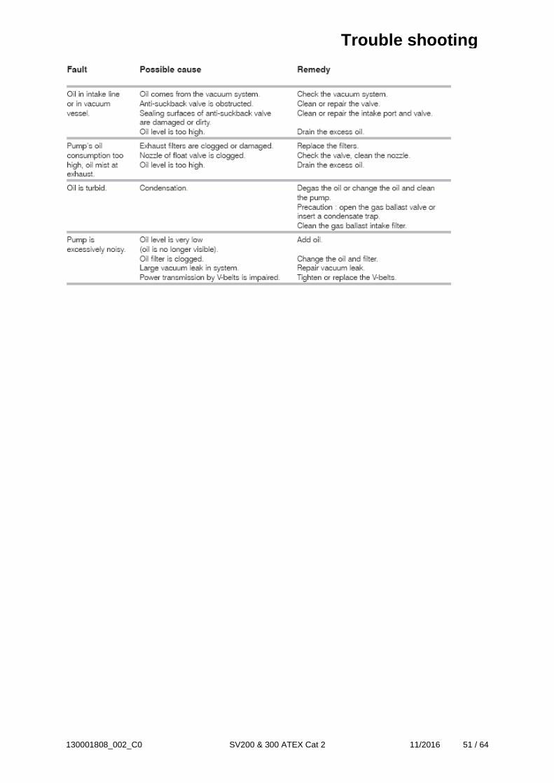
6 Trouble shooting
Trouble shooting
130001808_002_C0 SV200 & 300 ATEX Cat 2 11/2016 51 / 64
Trouble shooting
130001808_002_C0 SV200 & 300 ATEX Cat 2 11/2016 52 / 64
7 Spare parts To guarantee safe operation of the Leybold pump, only original & genuine spare parts and accessories should be used. When ordering spare parts and accessories, always state pump type and serial number. You can find part numbers in the spare parts list. The pump looses its ATEX certification if non genuine Leybold parts are used. Consumables and main spare parts kits for SOGEVAC® pumps are usually available on stock at Leybold’s service centres. The list of these parts is given here after and in the spare parts table where the contents of each kits is detailed. See § 1.8 & 1.9 for part references. Exhaust demisters Oils (Special oils please refer to the specific notice of the pump or contact Leybold). Maintenance kit Repair kit We recommend using these kits which have been defined to allow an optimal maintenance or repair. Individual spare parts may need longer delivery time.
Warning
Spare parts

130001808_002_C0 SV200 & 300 ATEX Cat 2 11/2016 53 / 64
SV300 ATEX CAT 2
Spare parts

130001808_002_C0 SV200 & 300 ATEX Cat 2 11/2016 54 / 64
SV300 ATEX CAT 2 Item Pos.
Designation Beschreibung Désignation Part-Nr. Sach-Nr Référence
1 OIL CASING SV300 ATEX CAT 2 OELKASTEN SV300 ATEX CAT 2 CARTER SV300 ATEX CAT2 971463020 1a GLASS OIL SIGHT GLASS GLASS OELSCHAUGLASS VOYANT D'HUILE 3/4 BSP VERRE 71219480 1b EXHAUST FILTER BYPASS AUSPUFFILTER BYPASS BY-PASS SURPRESSION CAA 71017930 2 GENERATOR SV300 ATEX CAT2 GENERATOR SV300 ATEX CAT2 GENERATEUR SV300 ATEX CAT2 971463010 3 COUPLING SV300 ATEX CAT2 KUPPLUNG SV300 ATEX CAT2 ACCOUPLEMENT SV300 ATEX CAT2 971463060 4 COUPLING HOUSING SV300 ATEX
CAT 2 KUPPLUNGSGEHÄUSE SV300 ATEX CAT 2
CLOCHE SV300 ATEX CAT2 971463050
5 MOTOR 7.5 kW 230/400 V, 50 Hz & 460 V, 60 Hz IICT4
MOTOR 7.5 kW 230/400 V, 50 Hz & 460 V, 60 Hz IICT4
MOTEUR 7.5 kW 230/400 V, 50 Hz & 460 V, 60 Hz IICT4
971461750
6 RUBBER FEET KIT SV300 ATEX CAT 2
GUMMI DAEMPFER KIT SV300 ATEX CAT2
KIT PIEDS SV300 ATEX CAT 2 971463090
7 OIL LEVEL SENSOR SV300 ATEX CAT 2
OELPEGELSENSOR SV300 ATEX CAT 2
CONTROLEUR DE NIVEAU SV300 ATEX CAT 2
971455680
8 PRESSURE SENSOR SV300 ATEX CAT 2
DRUCKSENSOR SV300 ATEX CAT 2 TRANSMETTEUR DE PRESSION SV300 ATEX CAT 2
971455790
9 SUCTION FLANGE G2" SAUGSTUTZEN G2" BRIDE ASPIRATION G2" 971463040 10 PIPE KIT SV300 ATEX CAT 2 OELLEITUNGS-KIT SV300 ATEX CAT
2 KIT CANALISATIONS SV300 ATEX CAT 2
971463080
11 PROBE PT100 SONDE PT100 SONDE PT100 971267430 12 GAS BALLAST 16KF SV300 ATEX
CAT 2 GASBALLAST 16KF SV300 ATEX CAT 2
LEST AIR 16KF SV300 ATEX CAT 2 971437530
12a GASBALLAST FILTER SV300 ATEX CAT 2
GASBALLAST FILTER SV300 ATEX CAT 2
FILTRE LEST D'AIR SV300 ATEX CAT 2
971442250
13 SET OF COVERS SV300 ATEX CAT 2 HAUBENKIT SV300 ATEX CAT 2 CAPOTAGE SV300 ATEX CAT 2 971463070 14 FLOAT VALVE SV300 ATEX CAT 2 SCHWIMMERVENTIL SV300 ATEX
CAT 2 FLOTTEUR SV300 ATEX CAT 2 971463030
Spare parts
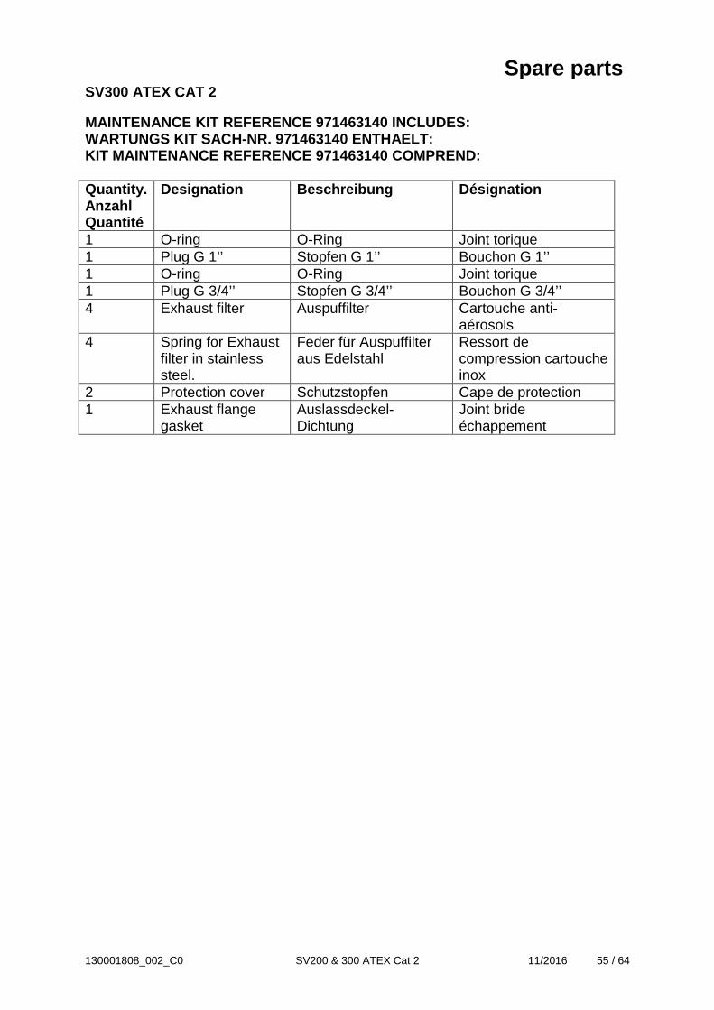
130001808_002_C0 SV200 & 300 ATEX Cat 2 11/2016 55 / 64
SV300 ATEX CAT 2 MAINTENANCE KIT REFERENCE 971463140 INCLUDES: WARTUNGS KIT SACH-NR. 971463140 ENTHAELT: KIT MAINTENANCE REFERENCE 971463140 COMPREND: Quantity. Anzahl Quantité
Designation Beschreibung Désignation
1 O-ring O-Ring Joint torique 1 Plug G 1’’ Stopfen G 1’’ Bouchon G 1’’ 1 O-ring O-Ring Joint torique 1 Plug G 3/4’’ Stopfen G 3/4’’ Bouchon G 3/4’’ 4 Exhaust filter Auspuffilter Cartouche anti-
aérosols 4 Spring for Exhaust
filter in stainless steel.
Feder für Auspuffilter aus Edelstahl
Ressort de compression cartouche inox
2 Protection cover Schutzstopfen Cape de protection 1 Exhaust flange
gasket Auslassdeckel-Dichtung
Joint bride échappement
Spare parts

130001808_002_C0 SV200 & 300 ATEX Cat 2 11/2016 56 / 64
SV300 ATEX CAT 2 REPAIR KIT REFERENCE 971463150 INCLUDES: REPARATUR KIT SACH-NR. 971463150 ENTHAELT: KIT REPARATION REFERENCE 971463150 COMPREND: Quantity. Anzahl Quantité
Designation Beschreibung Désignation
2 Half exhaust valve Halbes Auslassventil Demi lame 1 Valve stop Auslassventil-Anschlag Contre lame 1 Mounting
instructions valves Montageanleitung Auslassventile
Notice montage lames
1 Set of 3 vanes Satz von 3 Schiebern Jeu de 3 palettes 1 Gasket set Dichtungssatz Jeu de joints 2 Needle bearing Nadellager Roulement à aiguilles 1 Coupling sleeve Kupplungs-Manschette Manchon
accouplement 4 Exhaust filter Auspuffilter Cartouche anti-
aérosols 4 Spring for Exhaust
filter in stainless steel.
Feder für Auspuffilter aus Edelstahl
Ressort de compression cartouche inox
1 GB Filter GB Filter Filtre lest d’air 1 Rotor sleeves Rotorringe Bagues rotor 1 Glass oil sight glass Glass Ölschauglass Voyant d’huile verre 1 GAET SV300 ATEX
Cat 2 GAET SV300 ATEX Cat 2
GAET SV300 ATEX Cat 2
Spare parts

130001808_002_C0 SV200 & 300 ATEX Cat 2 11/2016 57 / 64
SV200 ATEX CAT 2
Spare parts

130001808_002_C0 SV200 & 300 ATEX Cat 2 11/2016 58 / 64
SV200 ATEX CAT 2 Item Pos.
Designation Beschreibung Désignation Part-Nr. Sach-Nr Référence
1 OIL CASING SV200 ATEX CAT 2 OELKASTEN SV200 ATEX CAT 2 CARTER SV200 ATEX CAT2 971463370 1a GLASS OIL SIGHT GLASS GLASS OELSCHAUGLASS VOYANT D'HUILE 3/4 BSP VERRE 71219480 1b EXHAUST FILTER BYPASS AUSPUFFILTER BYPASS BY-PASS SURPRESSION CAA 71017930 2 GENERATOR SV200 ATEX CAT2 GENERATOR SV200 ATEX CAT2 GENERATEUR SV000 ATEX CAT2 971463380 3 COUPLING SV200 ATEX CAT2 KUPPLUNG SV200 ATEX CAT2 ACCOUPLEMENT SV200 ATEX CAT2 971463060 4 COUPLING HOUSING SV200 ATEX
CAT 2 KUPPLUNGSGEHÄUSE SV200 ATEX CAT 2
CLOCHE SV200 ATEX CAT2 971463390
5 MOTOR 5.5 kW 230/400 V, 50 Hz & 460 V, 60 Hz IICT4
MOTOR 5.5 kW 230/400 V, 50 Hz & 460 V, 60 Hz IICT4
MOTEUR 5.5 kW 230/400 V, 50 Hz & 460 V, 60 Hz IICT4
971461740
6 RUBBER FEET KIT SV200 ATEX CAT 2
GUMMI DAEMPFER KIT SV200 ATEX CAT2
KIT PIEDS SV200 ATEX CAT 2 971463090
7 OIL LEVEL SENSOR SV200 ATEX CAT 2
OELPEGELSENSOR SV200 ATEX CAT 2
CONTROLEUR DE NIVEAU SV200 ATEX CAT 2
971455680
8 PRESSURE SENSOR SV200 ATEX CAT 2
DRUCKSENSOR SV200 ATEX CAT 2 TRANSMETTEUR DE PRESSION SV200 ATEX CAT 2
971455790
9 SUCTION FLANGE G2" SAUGSTUTZEN G2" BRIDE ASPIRATION G2" 971463040 10 PIPE KIT SV200 ATEX CAT 2 OELLEITUNGS-KIT SV200 ATEX CAT
2 KIT CANALISATIONS SV200 ATEX CAT 2
971463400
11 PROBE PT100 SONDE PT100 SONDE PT100 971267430 12 GAS BALLAST 16KF SV200 ATEX
CAT 2 GASBALLAST 16KF SV200 ATEX CAT 2
LEST AIR 16KF SV200 ATEX CAT 2 971463410
12a GASBALLAST FILTER SV300 ATEX CAT 2
GASBALLAST FILTER SV300 ATEX CAT 2
FILTRE LEST D'AIR SV300 ATEX CAT 2
971442250
13 SET OF COVERS SV200 ATEX CAT 2 HAUBENKIT SV200 ATEX CAT 2 CAPOTAGE SV200 ATEX CAT 2 971463420 14 FLOAT VALVE SV200 ATEX CAT 2 SCHWIMMERVENTIL SV200 ATEX
CAT 2 FLOTTEUR SV200 ATEX CAT 2 971463030
Spare parts

130001808_002_C0 SV200 & 300 ATEX Cat 2 11/2016 59 / 64
SV200 ATEX CAT 2 MAINTENANCE KIT REFERENCE 971463430 INCLUDES: WARTUNGS KIT SACH-NR. 971463430 ENTHAELT: KIT MAINTENANCE REFERENCE 971463430 COMPREND: Quantity. Anzahl Quantité
Designation Beschreibung Désignation
1 O-ring O-Ring Joint torique 1 Plug G 1’’ Stopfen G 1’’ Bouchon G 1’’ 1 O-ring O-Ring Joint torique 1 Plug G 3/4’’ Stopfen G 3/4’’ Bouchon G 3/4’’ 4 Exhaust filter Auspuffilter Cartouche anti-
aérosols 4 Spring for
Exhaust filter in stainless steel.
Feder für Auspuffilter aus Edelstahl
Ressort de compression cartouche inox
2 Protection cover Schutzstopfen Cape de protection 1 Exhaust flange
gasket Auslassdeckel-Dichtung
Joint bride échappement
Spare parts

130001808_002_C0 SV200 & 300 ATEX Cat 2 11/2016 60 / 64
SV200 ATEX CAT 2 REPAIR KIT REFERENCE 971463440 INCLUDES: REPARATUR KIT SACH-NR. 971463440 ENTHAELT: KIT REPARATION REFERENCE 971463440 COMPREND: Quantity. Anzahl Quantité
Designation Beschreibung Désignation
1 Exhaust valve Auslassventil Lame 1 Valve stop Auslassventil-Anschlag Contre lame 1 Mounting
instructions valves
Montageanleitung Auslassventile
Notice montage lames
1 Set of 3 vanes Satz von 3 Schiebern Jeu de 3 palettes 1 Gasket set Dichtungssatz Jeu de joints 2 Needle bearing Nadellager Roulement à aiguilles 1 Coupling
sleeve Kupplungs-Manschette Manchon
accouplement 4 Exhaust filter Auspuffilter Cartouche anti-
aérosols 4 Spring for
Exhaust filter in stainless steel.
Feder für Auspuffilter aus Edelstahl
Ressort de compression cartouche inox
1 GB Filter GB Filter Filtre lest d’air 1 Rotor sleeves Rotorringe Bagues rotor 1 Glass oil sight
glass Glass Ölschauglass Voyant d’huile verre
1 GAET SV300 ATEX Cat 2
GAET SV300 ATEX Cat 2
GAET SV300 ATEX Cat 2
Spare parts
EU Declaration

130001808_002_C0 SV200 & 300 ATEX Cat 2 11/2016 61 / 64

130001808_002_C0 SV200 & 300 ATEX Cat 2 11/2016 62 / 64
Declaration of Contamination

130001808_002_C0 SV200 & 300 ATEX Cat 2 11/2016 63 / 64
Notes
Notes
130001808_002_C0 SV200 & 300 ATEX Cat 2 11/2016 64 / 64