Software UART using ST7LITE0 12-bit autoreload · PDF fileSoftware UART using ST7LITE0 12-bit...
22
March 2013 DocID9986 Rev 2 1/22 AN1753 Application note Software UART using ST7LITE0 12-bit autoreload timer Introduction This application note describes a software implementation of a Universal Asynchronous Receiver/Transmitter (UART). This can be used on devices with no on-chip SCI peripheral. In this example, a software UART is implemented for the ST7LITE0, using the 12-bit Autoreload timer and two I/O ports for asynchronous receive and transmit. The UART software provides the following features: • Half-duplex operation • Asynchronous operation • Flexible data formats (7 or 8 data bits, 1 or 2 stop bits) • Baud rate: 2400 to 19200 baud To test this interrupt-driven software UART, you can use the “Hyperterminal” application running on a Windows PC. The program code is quite small (357 bytes) and can easily be adapted to specific application requirements. Table 1 lists the microcontrollers and software concerned by this application note. Table 1. Applicable products and software Type Part numbers or product categories Microcontrollers ST7LITE02Y0, ST7LITE05Y0, ST7LITE09Y0 Software STSW-ST7094 www.st.com
Transcript of Software UART using ST7LITE0 12-bit autoreload · PDF fileSoftware UART using ST7LITE0 12-bit...
March 2013 DocID9986 Rev 2 1/22
AN1753Application note
Software UART using ST7LITE0 12-bit autoreload timer
Introduction
This application note describes a software implementation of a Universal Asynchronous Receiver/Transmitter (UART). This can be used on devices with no on-chip SCI peripheral.
In this example, a software UART is implemented for the ST7LITE0, using the 12-bit Autoreload timer and two I/O ports for asynchronous receive and transmit. The UART software provides the following features:
• Half-duplex operation
• Asynchronous operation
• Flexible data formats (7 or 8 data bits, 1 or 2 stop bits)
• Baud rate: 2400 to 19200 baud
To test this interrupt-driven software UART, you can use the “Hyperterminal” application running on a Windows PC.
The program code is quite small (357 bytes) and can easily be adapted to specific application requirements.
Table 1 lists the microcontrollers and software concerned by this application note.
Table 1. Applicable products and software
Type Part numbers or product categories
Microcontrollers ST7LITE02Y0, ST7LITE05Y0, ST7LITE09Y0
Software STSW-ST7094
www.st.com
Contents AN1753
2/22 DocID9986 Rev 2
Contents
1 UART communication . . . . . . . . . . . . . . . . . . . . . . . . . . . . . . . . . . . . . . . . 4
1.1 Main features . . . . . . . . . . . . . . . . . . . . . . . . . . . . . . . . . . . . . . . . . . . . . . . 4
1.2 Baud rate . . . . . . . . . . . . . . . . . . . . . . . . . . . . . . . . . . . . . . . . . . . . . . . . . . 4
1.3 Frame . . . . . . . . . . . . . . . . . . . . . . . . . . . . . . . . . . . . . . . . . . . . . . . . . . . . . 4
2 RS232 communication with a PC . . . . . . . . . . . . . . . . . . . . . . . . . . . . . . . 6
2.1 Main features . . . . . . . . . . . . . . . . . . . . . . . . . . . . . . . . . . . . . . . . . . . . . . . 6
2.2 PC configuration . . . . . . . . . . . . . . . . . . . . . . . . . . . . . . . . . . . . . . . . . . . . . 6
3 ST7FLITE0 configuration . . . . . . . . . . . . . . . . . . . . . . . . . . . . . . . . . . . . . 7
3.1 Clock source . . . . . . . . . . . . . . . . . . . . . . . . . . . . . . . . . . . . . . . . . . . . . . . . 7
3.2 Input initialization . . . . . . . . . . . . . . . . . . . . . . . . . . . . . . . . . . . . . . . . . . . . 7
3.3 Auto-reload timer register configuration . . . . . . . . . . . . . . . . . . . . . . . . . . . 7
4 UART implementation . . . . . . . . . . . . . . . . . . . . . . . . . . . . . . . . . . . . . . . . 9
4.1 Baud rate definition . . . . . . . . . . . . . . . . . . . . . . . . . . . . . . . . . . . . . . . . . . 9
4.2 Majority-voting system . . . . . . . . . . . . . . . . . . . . . . . . . . . . . . . . . . . . . . . . 9
4.3 Status handling . . . . . . . . . . . . . . . . . . . . . . . . . . . . . . . . . . . . . . . . . . . . . 10
4.4 Transmit and receive implementation . . . . . . . . . . . . . . . . . . . . . . . . . . . . 10
5 Hardware setup . . . . . . . . . . . . . . . . . . . . . . . . . . . . . . . . . . . . . . . . . . . . 11
6 Functional software flow . . . . . . . . . . . . . . . . . . . . . . . . . . . . . . . . . . . . 12
6.1 Main software routines . . . . . . . . . . . . . . . . . . . . . . . . . . . . . . . . . . . . . . . 12
6.2 Software flow charts . . . . . . . . . . . . . . . . . . . . . . . . . . . . . . . . . . . . . . . . . 13
7 Test procedure . . . . . . . . . . . . . . . . . . . . . . . . . . . . . . . . . . . . . . . . . . . . . 19
8 Software . . . . . . . . . . . . . . . . . . . . . . . . . . . . . . . . . . . . . . . . . . . . . . . . . . 20
9 Revision history . . . . . . . . . . . . . . . . . . . . . . . . . . . . . . . . . . . . . . . . . . . 21
DocID9986 Rev 2 3/22
AN1753 List of figures
List of figures
Figure 1. ST7 UART communication set-up . . . . . . . . . . . . . . . . . . . . . . . . . . . . . . . . . . . . . . . . . . . . 4Figure 2. Frames . . . . . . . . . . . . . . . . . . . . . . . . . . . . . . . . . . . . . . . . . . . . . . . . . . . . . . . . . . . . . . . . . 5Figure 3. Majority-voting system . . . . . . . . . . . . . . . . . . . . . . . . . . . . . . . . . . . . . . . . . . . . . . . . . . . . . 9Figure 4. Test Setup . . . . . . . . . . . . . . . . . . . . . . . . . . . . . . . . . . . . . . . . . . . . . . . . . . . . . . . . . . . . . 11Figure 5. Main flowchart. . . . . . . . . . . . . . . . . . . . . . . . . . . . . . . . . . . . . . . . . . . . . . . . . . . . . . . . . . . 13Figure 6. Output compare interrupt . . . . . . . . . . . . . . . . . . . . . . . . . . . . . . . . . . . . . . . . . . . . . . . . . . 13Figure 7. Transmit routine . . . . . . . . . . . . . . . . . . . . . . . . . . . . . . . . . . . . . . . . . . . . . . . . . . . . . . . . . 14Figure 8. Receive data routine. . . . . . . . . . . . . . . . . . . . . . . . . . . . . . . . . . . . . . . . . . . . . . . . . . . . . . 15Figure 9. Output compare transmit flow. . . . . . . . . . . . . . . . . . . . . . . . . . . . . . . . . . . . . . . . . . . . . . . 16Figure 10. Output compare receive flow . . . . . . . . . . . . . . . . . . . . . . . . . . . . . . . . . . . . . . . . . . . . . . . 17Figure 11. EI1 interrupt routine . . . . . . . . . . . . . . . . . . . . . . . . . . . . . . . . . . . . . . . . . . . . . . . . . . . . . . 18
UART communication AN1753
4/22 DocID9986 Rev 2
1 UART communication
The main features of a standard UART are summarized below.
1.1 Main features
The UART offers a flexible means of full-duplex data exchange with external equipment requiring an industry standard NRZ asynchronous serial data format.
The UART allows a very wide range of baud rates and different baud rates for transmission and reception.
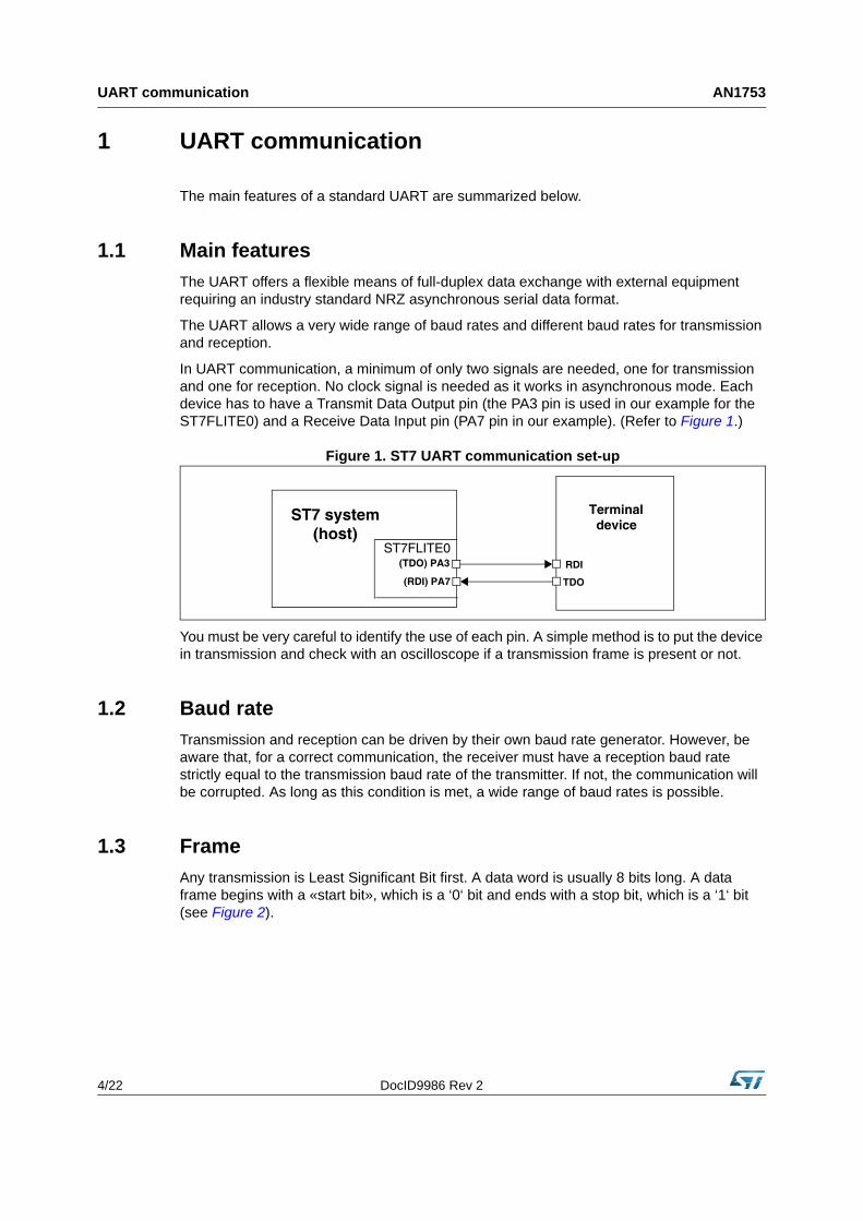
In UART communication, a minimum of only two signals are needed, one for transmission and one for reception. No clock signal is needed as it works in asynchronous mode. Each device has to have a Transmit Data Output pin (the PA3 pin is used in our example for the ST7FLITE0) and a Receive Data Input pin (PA7 pin in our example). (Refer to Figure 1.)
Figure 1. ST7 UART communication set-up
You must be very careful to identify the use of each pin. A simple method is to put the device in transmission and check with an oscilloscope if a transmission frame is present or not.
1.2 Baud rate
Transmission and reception can be driven by their own baud rate generator. However, be aware that, for a correct communication, the receiver must have a reception baud rate strictly equal to the transmission baud rate of the transmitter. If not, the communication will be corrupted. As long as this condition is met, a wide range of baud rates is possible.
1.3 Frame
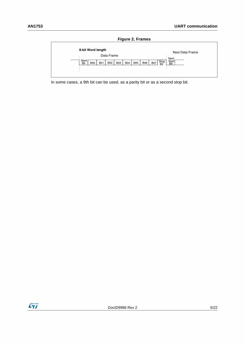
Any transmission is Least Significant Bit first. A data word is usually 8 bits long. A data frame begins with a «start bit», which is a ‘0‘ bit and ends with a stop bit, which is a ‘1‘ bit (see Figure 2).
ST7 system
RDI
TDO
Terminaldevice
(TDO) PA3
(RDI) PA7
ST7FLITE0(host)
DocID9986 Rev 2 5/22
AN1753 UART communication
Figure 2. Frames
In some cases, a 9th bit can be used, as a parity bit or as a second stop bit.
Bit0 Bit1 Bit2 Bit3 Bit4 Bit5 Bit6 Bit7StartBit
StopBit
NextStart Bit
8-bit Word length
Data FrameNext Data Frame
RS232 communication with a PC AN1753
6/22 DocID9986 Rev 2
2 RS232 communication with a PC
2.1 Main features
Electrical and protocol characteristics of RS232 are different from those used by the UART. In RS232 communication, high level is typically +7V and low level is typically -7V, while the ST7LITE0 I/Os work at CMOS levels (0, +5V).
Furthermore, the polarities are different. A ‘1‘ bit coming from the UART corresponds to a ‘0‘ bit in RS232, and a ‘0‘ bit to a ‘1‘ bit. It is true for all bits including the start and stop bits. So it is necessary to implement a conversion between the PC and the ST7LITE0. In the application, a MAX232 is used for this purpose.
2.2 PC configuration
The PC will be used as a terminal interface. “Hyperterminal”, the terminal application software, is used as an interfacing software to test the function [.zip file attached]. The test environment is Windows.
Under Windows, open the Hyperterminal application. To configure it, go to the port settings and set the parameters to your application requirements. The options in this window must be the same as the ones defined for your ST7FLITE0 communication device, except the port.
After selecting the right serial communication port, select the same baud rate as the one set for the ST7LITE0. As the PC accepts only one baud rate, transmission and reception baud rates will have the same value. Data word can be 8/7 bits, but you can choose to use 1 or 2 stop bits.
«Flow control» can be either Xon/Xoff or none. The PC is then correctly configured.
DocID9986 Rev 2 7/22
AN1753 ST7FLITE0 configuration
3 ST7FLITE0 configuration
3.1 Clock source
This application is implemented using an ST7FLITE0 device with an 8 MHz internal clock. PLL * 8 is used to generate this 8 MHz clock.
3.2 Input initialization
Two pins of the ST7FLITE0 are used:
• PA3: pin of PortA
• PA7: pin of PortA with interrupt
Pin PA3 is a normal input/output port pin with no alternate function, used for transmission. During the initialization, it is configured as an output.
Pin PA7 is a normal input/output port pin with no alternate function, used for data receive. During the initialization, it is configured as an input. While in receive mode, at start, the same pin is used with interrupt enabled (“ei1”) to sense the start bit. So this pin is configured with “pull up interrupt input” by setting PADDR to 0 & PAOR to 1. To set the interrupt sensitivity “Falling edge only”, you have to set IS11=1 & IS10=0 in the EICR register.
Refer to the device datasheet for a detailed description of the I/O and interrupt control registers.
3.3 Auto-reload timer register configuration
The AT timer is based on a free running 12-bit upcounter with 12-bit auto reload register (ATR). Apart from this, it also includes other functions such as PWM signal generator, Output Compare Function, etc.
The “Output Compare” function is used for this application. To use it, the OE bit must be 0, otherwise the compare is done with the shadow register instead of the DCRx register. The software must then write a 12-bit value in the DCR0H and DCR0L registers. When the 12-bit upcounter (CNTR) reaches the value stored in the DCR0H and DCR0L registers, the CMPF0 bit in the PWM0CSR register is set and an interrupt request is generated, provided that the CMPIE bit is set.
The registers that are used in the application note are:
TIMER CONTROL STATUS REGISTER (ATCSR):
• CK1, CK0: select the clock frequency of the counter.
– For fcounter = fcpu, set CK1=1 and CK0=0
• CMPIE: allows to mask the interrupt generation when the CMPF bit is set:
– 0: the CMPF interrupt is disabled
– 1: the CMPF interrupt is enabled
CMPIEOVFIEOVFCK0CK1000
ST7FLITE0 configuration AN1753
8/22 DocID9986 Rev 2
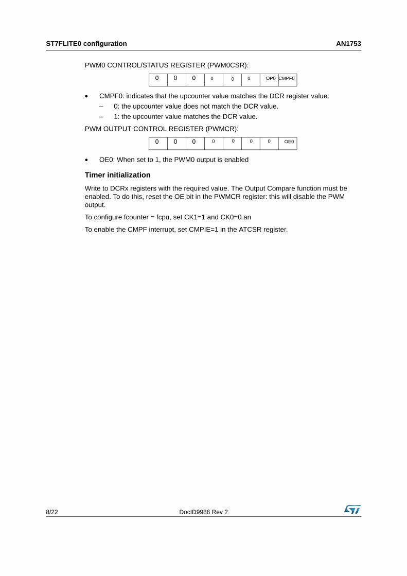
PWM0 CONTROL/STATUS REGISTER (PWM0CSR):
• CMPF0: indicates that the upcounter value matches the DCR register value:
– 0: the upcounter value does not match the DCR value.
– 1: the upcounter value matches the DCR value.
PWM OUTPUT CONTROL REGISTER (PWMCR):
• OE0: When set to 1, the PWM0 output is enabled
Timer initialization
Write to DCRx registers with the required value. The Output Compare function must be enabled. To do this, reset the OE bit in the PWMCR register: this will disable the PWM output.
To configure fcounter = fcpu, set CK1=1 and CK0=0 an
To enable the CMPF interrupt, set CMPIE=1 in the ATCSR register.
CMPF0000000 OP0
000 OE00000
DocID9986 Rev 2 9/22
AN1753 UART implementation
4 UART implementation
4.1 Baud rate definition
The Autoreload timer is used to generate the baud rate. The autoreload timer clock (fCOUNTER) is the same as the fcpu clock, which is an 8 MHz internal clock.
The example below describes how this baud is generated:
- baudrate = 2400
- fcpu = 8MHz (so clock period is 125 ns)
- In the application fCOUNTER = fcpu
So to get 2400 baud the “Prescaler” required is,
Prescaler = fcpu / baud
Prescaler = 8 * 106 / 2400
= 0.0033333333 * 106
= 3333.33 decimal
= D05 Hex (= 1 bit delay count)
So in software DCRx will be
DCR0H = 0D + CNTRH
DCR0L = 05 + CNTRL
to generate one bit delay when 2400 baud is required
For half bit period “Prescaler” is,
Prescaler = one bit / 2
= 1666.66 (decimal)
= 682 Hex (= 1/2 bit delay)
DCR0H = 06 + CNTRH
DCR0L = 82 + CNTRL
The software provided with this application note has been functionally tested in the range 2400 to 19200 baud.
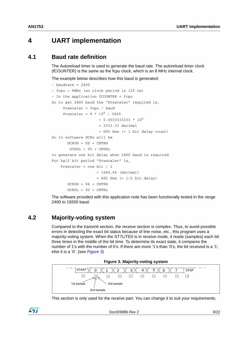
4.2 Majority-voting system
Compared to the transmit section, the receive section is complex. Thus, to avoid possible errors in detecting the exact bit status because of line noise, etc., this program uses a majority-voting system. When the ST7LITE0 is in receive mode, it reads (samples) each bit three times in the middle of the bit time. To determine its exact state, it compares the number of 1’s with the number of 0’s. If there are more ‘1‘s than ‘0‘s, the bit received is a ‘1‘, else it is a ‘0‘. (see Figure 3)
Figure 3. Majority-voting system
This section is only used for the receive part. You can change it to suit your requirements.
0 1 2 3 4 5 6 7
1st sample
2nd sample
3rd sample
START STOP
UART implementation AN1753
10/22 DocID9986 Rev 2
4.3 Status handling
To keep track of the status during a program execution, the software uses the “sci_status” variable. Bits 0-4 of this variable are used to hold the system status.
Definition of each flag:
SP: Reception mode sampling phase
BR: Byte Received flag
RE: Reception Enable
BS: Byte Sent flag
TE: Transmission Enable
4.4 Transmit and receive implementation
The transmission mode gets executed after power on. To transmit data, the program uses port pin PA3 in output mode with the “Output Compare” interrupt. One bit is transmitted during each interrupt, generated after a bit delay when the 12-bit upcounter (CNTR) reaches the value (=1 bit delay) stored in the DCR0H and DCR0L registers. For a duty cycle register (DCR0L/DCR0H), the value depends on the required baud rate and clock frequency.
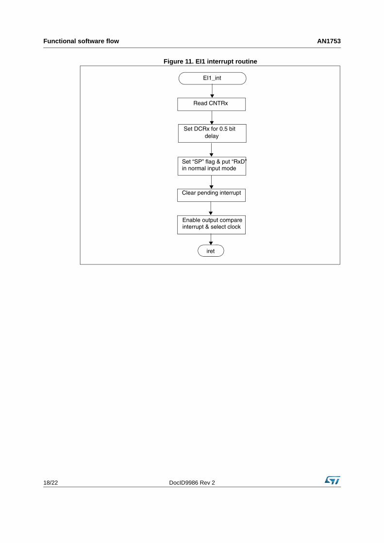
For receive mode, the program uses port pin PA7 in input mode along with its interrupt and output compare functions. To sense the start bit, the “ei1” interrupt is used and configured as “Falling edge only”. In this interrupt routine, the program sets the ATR - the output compare value for a half bit delay(a) - and disables the “ei1” interrupt to use PA7 in normal input mode, in order to receive the entire frame. This half bit delay is used to sample a bit in the middle of it. After receiving a start bit in an output compare interrupt, the same interrupt routine gets executed each time a bit must be received. To receive each bit correctly, the majority-voting system is implemented in this interrupt routine.
The interrupt strategy used in the software to transmit and receive allows other applications to work at the same time.
Note: Error handling: This program does not handle communication errors (e.g. Frame Errors).
No handshaking is implemented.
For better performance at high baud rates, it is recommended to use character transmission rather than string transmission.
SPBRREBSTE
a. The user can adjust this value depending on the baud rate.
DocID9986 Rev 2 11/22
AN1753 Hardware setup
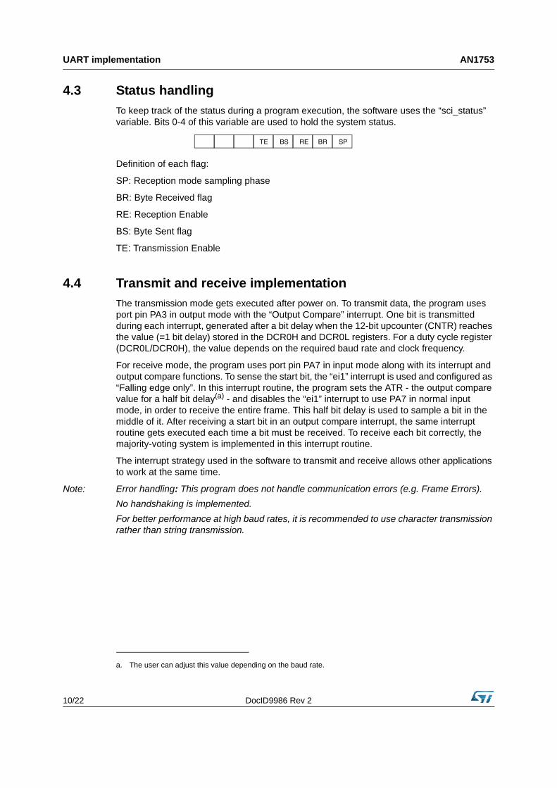
5 Hardware setup
A general system configuration is shown in Figure 1. The ST7FLITE0 is connected to an RS-232 line driver chip which is in turn connected to any RS-232-compatible device. The RS-232 line driver is needed to convert the 5-volt logic level of the ST7FLITE0 to the proper RS-232 line voltages, and vice versa.
Figure 4 shows a specific example of a hardware setup required for UART in which the ST7FLITE0 processor and RS-232 Driver/ Receiver are used. You can use different driver/receiver in your application. For example, you can use an MC14C88/ 89 as a low cost solution.
The Receive Data pin (RD) of the PC serial port must correspond to the PA3 pin of the ST7FLITE0, and the Transmit Data pin (TD) to the PA7 pin.
Caution: The three main devices (PC, ST7LITE0, MAX232) must have the same electrical reference (GND). For a detailed description of MAX232, please refer to the datasheet.
Figure 4. Test Setup
PC
TERMINAL
serial port TDRD
GROUND
MAX232
IN OUTOUTIN
ST7FLITE0
GND
GND
GND
PA7 pin PA3 pin
Functional software flow AN1753
12/22 DocID9986 Rev 2
6 Functional software flow
The character format used is “ASCII”. Before starting a communication, you should configure the communication parameters to your requirements. You can select the baud rate, number of bits and stop bits in different combinations. However, for a correct communication, the receiver must have a reception baud rate strictly equal to the transmission baud rate of the transmitter. If not, the communication will be corrupted. So you have to configure the “Hyperterminal” correctly.
To configure the device, you must set del_1bh, del_1bl, del_sampl, del_samph, STOP_BIT and TxRx_data_lnth correctly in your software.
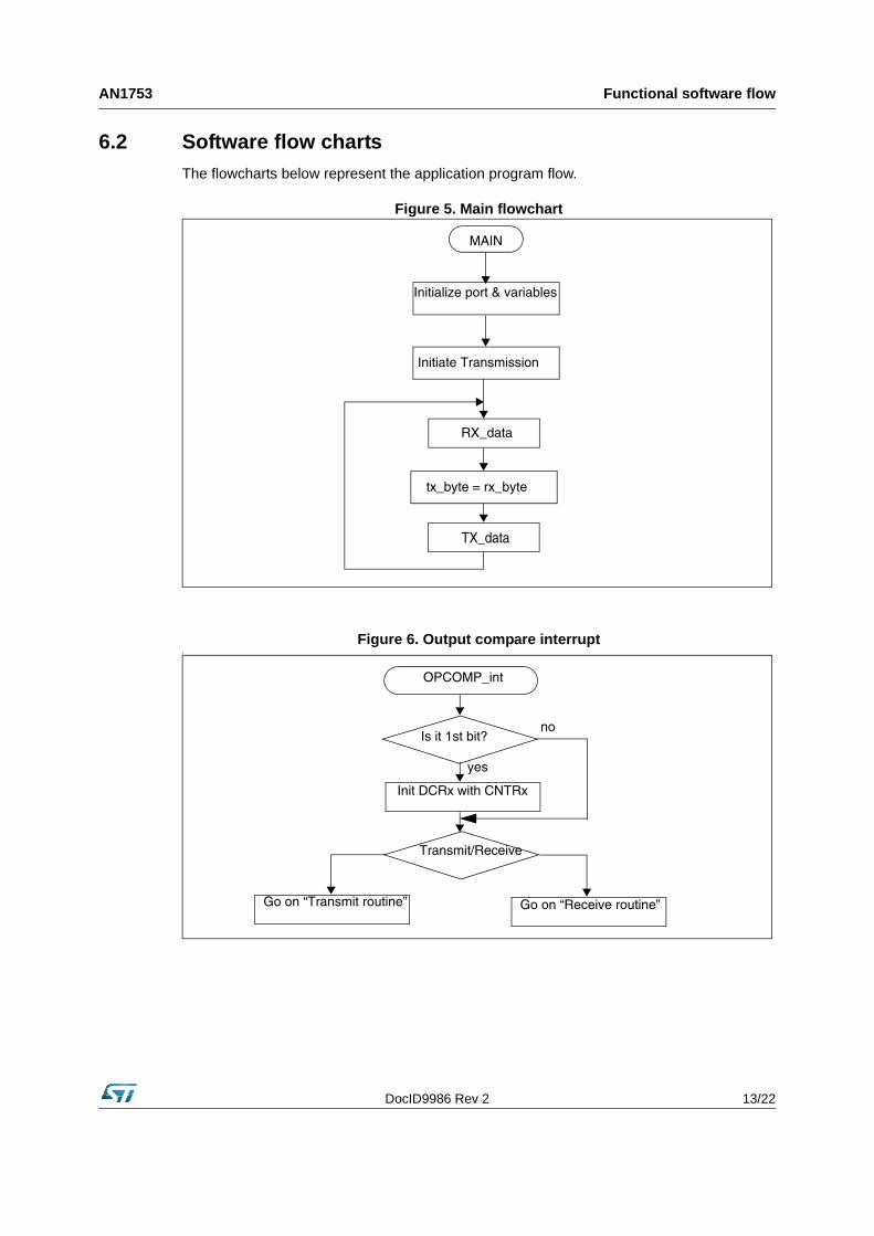
After power on, the ST7FLITE0 goes to transmit mode. It initiates the communication by transmitting character “$” in ASCII format and then goes to receive mode. The PC then receives this character on its serial port, which can be viewed in the Hyperterminal window.
You then have to press a key (character) to transmit. After pressing a character key, it gets transmitted and the ST7LITE0 receives it. The ST7LITE0 then sends the same received character to the PC. This sequence can be repeated continuously (see Figure 5).
6.1 Main software routines
The UART software consists of 4 main routines:
• Tx_data
• Rx_data
• EI1_Interrupt
• OPCOMP_int
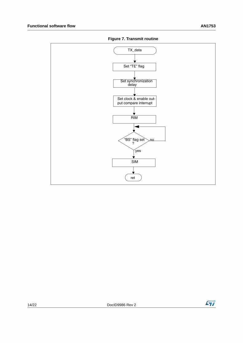
Tx_data: This routine is used to transmit data in bit format stored in variable “TX_byte”. It also takes care of the synchronization and of the output compare interrupt. The AT timer is initialized to the application configuration inside this routine.
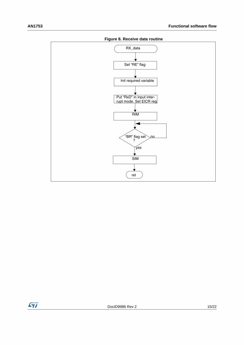
Rx_data: This routine is used to receive data on the input pin in bit format and stores it in “RX_byte”. To detect a start bit, it initializes the PA7 pin in interrupt mode.
EI1_Interrupt: This “ei1” interrupt routine gets executed only once during receive data when PA7 receives a start (high to low edge) bit. It also initiates the AT timer for a half bit duration.
OPCOMP_int: This routine gets executed in both transmit and receive modes. During a Tx_dataroutine execution, it gets executed for each data bit transfer. It is actually used to transmit data on the TxD (PA3) pin along with the start and stop bits.
In receive mode, it gets executed for each data bit received, including the start and stop bits.
The majority-voting system is implemented in the same section of code.
DocID9986 Rev 2 13/22
AN1753 Functional software flow
6.2 Software flow charts
The flowcharts below represent the application program flow.
Figure 5. Main flowchart
Figure 6. Output compare interruptt
RX_data
TX_data
tx_byte = rx_byte
MAIN
Initialize port & variables
Initiate Transmission
Is it 1st bit? no
yes
Init DCRx with CNTRx
Transmit/Receive
Go on “Transmit routine” Go on “Receive routine”
OPCOMP_int
Functional software flow AN1753
14/22 DocID9986 Rev 2
Figure 7. Transmit routine
Set “TE” flag
ret
“BS” flag set?
TX_data
Set clock & enable out-
Set synchronization delay
RIM
SIM
put compare interrupt
no
yes
DocID9986 Rev 2 15/22
AN1753 Functional software flow
Figure 8. Receive data routine
RX_data
Set “RE” flag
Init required variable
Put “RxD” in input inter-rupt mode. Set EICR reg.
ret
“BR” flag set?
no
yes
RIM
SIM
Functional software flow AN1753
16/22 DocID9986 Rev 2
Figure 9. Output compare transmit flow
Transmit routine
Send “START” bit
yes
no
a
bit_count=“0”
Set “BS” flag in “sci_status” var.
Disable interrupt & stoptimer clock
b
Send “STOP”bit
a
All “data”sent?
no
yes
yes
no
Transmit “data” bit
Load “CNTR” with 1 bit delay count
Clear prev. interrupt &set compare interrupt
iret
b
?
”FRAME”sent?
DocID9986 Rev 2 17/22
AN1753 Functional software flow
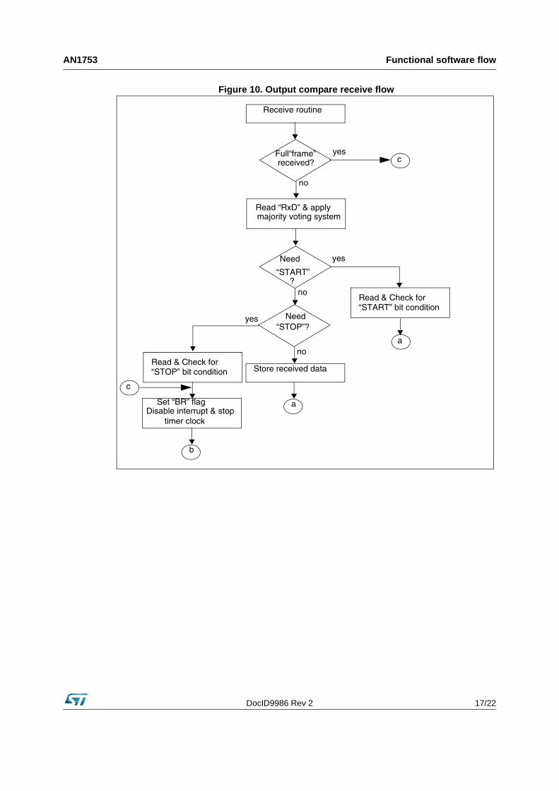
Figure 10. Output compare receive flow
Receive routine
yes
no
b
Full“frame”
a
Set “BR” flag
Disable interrupt & stoptimer clock
received?
Read “RxD” & apply majority voting system
“START”
yes
no
no
Needyes
?
Read & Check for
“STOP”?
Need
Read & Check for
Store received data
c
c
a
“START” bit condition
“STOP” bit condition
Functional software flow AN1753
18/22 DocID9986 Rev 2
Figure 11. EI1 interrupt routine
iret
Read CNTRx
Set DCRx for 0.5 bit
Set “SP” flag & put “RxD”in normal input mode
Clear pending interrupt
Enable output compare interrupt & select clock
EI1_int
delay
DocID9986 Rev 2 19/22
AN1753 Test procedure
7 Test procedure
1. Connect both the communication and terminal equipment as shown in Figure 4.
2. Open and configure the “Hyperterminal “application [Port, Baud rate, etc.].
3. Power on the ST7LITE0.
4. On the terminal, you should get “$” as a starting character (If not, then check the link between the terminal and the ST7LITE0 and check the communication settings).
5. Press a key to send a character.
6. The same character should be returned by the ST7LITE0 (check the “Hyperterminal” window).
7. Continue by repeating the two previous steps.
Software AN1753
20/22 DocID9986 Rev 2
8 Software
The complete software can be found on the ST internet website in a zipped file format. It is intended for use as an example only. It is up to you to adapt it to your specific application.
The source file is for guidance only. STMicroelectronics shall not be held liable for any direct, indirect or consequential damages with respect to any claims arising from use of this software.
DocID9986 Rev 2 21/22
AN1753 Revision history
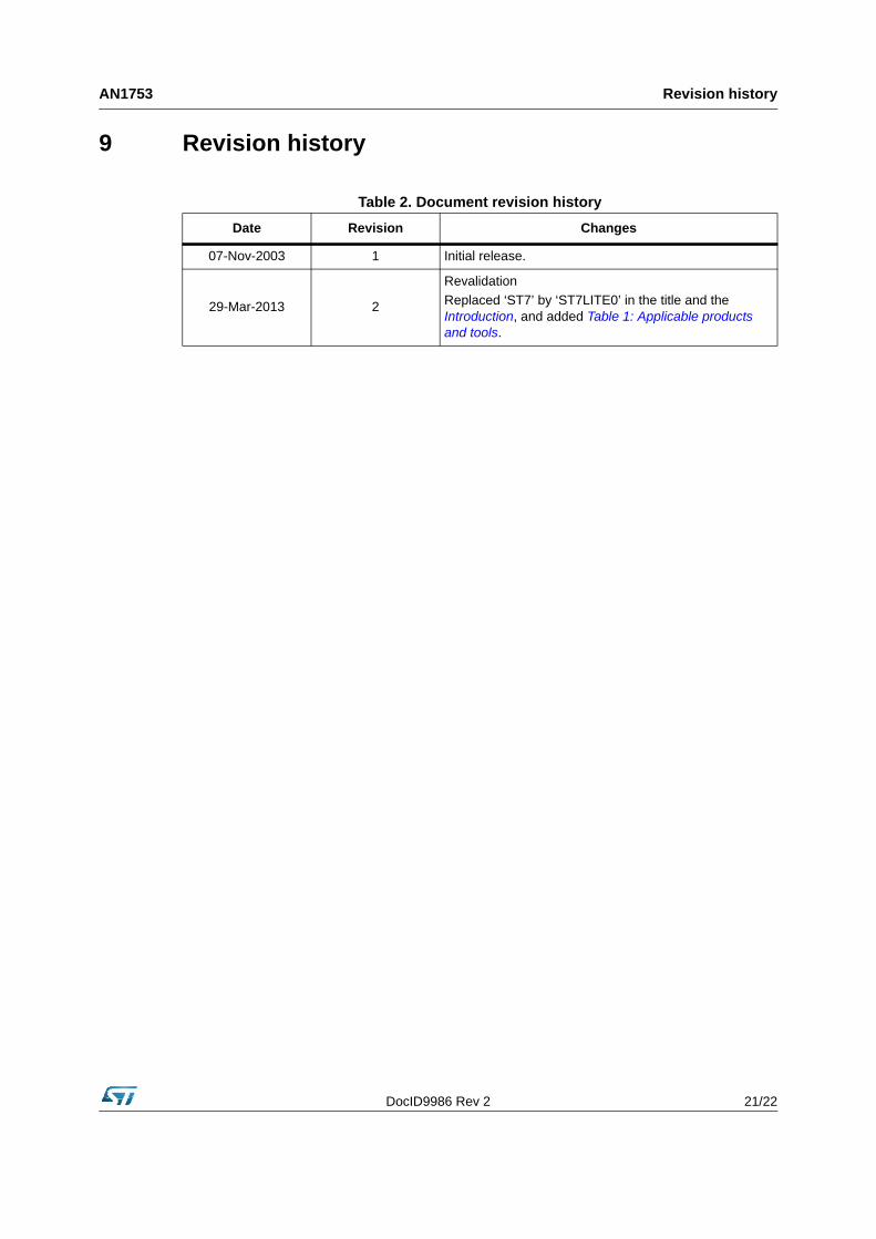
9 Revision history
Table 2. Document revision history
Date Revision Changes
07-Nov-2003 1 Initial release.
29-Mar-2013 2
Revalidation
Replaced ‘ST7’ by ‘ST7LITE0’ in the title and the Introduction, and added Table 1: Applicable products and tools.
AN1753
22/22 DocID9986 Rev 2
Please Read Carefully:
Information in this document is provided solely in connection with ST products. STMicroelectronics NV and its subsidiaries (“ST”) reserve theright to make changes, corrections, modifications or improvements, to this document, and the products and services described herein at anytime, without notice.
All ST products are sold pursuant to ST’s terms and conditions of sale.
Purchasers are solely responsible for the choice, selection and use of the ST products and services described herein, and ST assumes noliability whatsoever relating to the choice, selection or use of the ST products and services described herein.
No license, express or implied, by estoppel or otherwise, to any intellectual property rights is granted under this document. If any part of thisdocument refers to any third party products or services it shall not be deemed a license grant by ST for the use of such third party productsor services, or any intellectual property contained therein or considered as a warranty covering the use in any manner whatsoever of suchthird party products or services or any intellectual property contained therein.
UNLESS OTHERWISE SET FORTH IN ST’S TERMS AND CONDITIONS OF SALE ST DISCLAIMS ANY EXPRESS OR IMPLIEDWARRANTY WITH RESPECT TO THE USE AND/OR SALE OF ST PRODUCTS INCLUDING WITHOUT LIMITATION IMPLIEDWARRANTIES OF MERCHANTABILITY, FITNESS FOR A PARTICULAR PURPOSE (AND THEIR EQUIVALENTS UNDER THE LAWSOF ANY JURISDICTION), OR INFRINGEMENT OF ANY PATENT, COPYRIGHT OR OTHER INTELLECTUAL PROPERTY RIGHT.
ST PRODUCTS ARE NOT AUTHORIZED FOR USE IN WEAPONS. NOR ARE ST PRODUCTS DESIGNED OR AUTHORIZED FOR USEIN: (A) SAFETY CRITICAL APPLICATIONS SUCH AS LIFE SUPPORTING, ACTIVE IMPLANTED DEVICES OR SYSTEMS WITHPRODUCT FUNCTIONAL SAFETY REQUIREMENTS; (B) AERONAUTIC APPLICATIONS; (C) AUTOMOTIVE APPLICATIONS ORENVIRONMENTS, AND/OR (D) AEROSPACE APPLICATIONS OR ENVIRONMENTS. WHERE ST PRODUCTS ARE NOT DESIGNEDFOR SUCH USE, THE PURCHASER SHALL USE PRODUCTS AT PURCHASER’S SOLE RISK, EVEN IF ST HAS BEEN INFORMED INWRITING OF SUCH USAGE, UNLESS A PRODUCT IS EXPRESSLY DESIGNATED BY ST AS BEING INTENDED FOR “AUTOMOTIVE,AUTOMOTIVE SAFETY OR MEDICAL” INDUSTRY DOMAINS ACCORDING TO ST PRODUCT DESIGN SPECIFICATIONS.PRODUCTS FORMALLY ESCC, QML OR JAN QUALIFIED ARE DEEMED SUITABLE FOR USE IN AEROSPACE BY THECORRESPONDING GOVERNMENTAL AGENCY.
Resale of ST products with provisions different from the statements and/or technical features set forth in this document shall immediately voidany warranty granted by ST for the ST product or service described herein and shall not create or extend in any manner whatsoever, anyliability of ST.
ST and the ST logo are trademarks or registered trademarks of ST in various countries.Information in this document supersedes and replaces all information previously supplied.
The ST logo is a registered trademark of STMicroelectronics. All other names are the property of their respective owners.
© 2013 STMicroelectronics - All rights reserved
STMicroelectronics group of companies
Australia - Belgium - Brazil - Canada - China - Czech Republic - Finland - France - Germany - Hong Kong - India - Israel - Italy - Japan - Malaysia - Malta - Morocco - Philippines - Singapore - Spain - Sweden - Switzerland - United Kingdom - United States of America
www.st.com


![DESIGN OF 32-BIT MICROCONTROLLER … has 32-bit RICS microprocessor, data cache, instruction cache, FLASH controller, SDRAM controller, DMA (dynamic memory access), UART [7] (universal](https://static.fdocuments.in/doc/165x107/5adcdd157f8b9a9d4d8c5818/design-of-32-bit-microcontroller-has-32-bit-rics-microprocessor-data-cache.jpg)