Alroc 8YR0-LHS Bonded Semi-Conductor Screen Removal Tools - Alroc Screen Stripping Tools

May 16-17, 2001 - FEMCIWorkshop
NASA/GSFC - Code 542 Farhad Tahmasebi - 1
Software Tools for Analysis of BondedJoints
Farhad Tahmasebi, Ph.D.NASA/GSFC - Code 542

May 16-17, 2001 - FEMCI Workshop NASA/GSFC - Code 542 Farhad Tahmasebi - 2
Outline
• Spring modeling– Procedure– Spring stiffness values
• Description of the adhesive stress program• Description of the adhesive strain program• Inputs to & outputs from the programs
– NASTRAN input & output files ⇒ Program inputs• Mathematica 3D plots

May 16-17, 2001 - FEMCI Workshop NASA/GSFC - Code 542 Farhad Tahmasebi - 3
Spring Modeling Procedure (1/3)
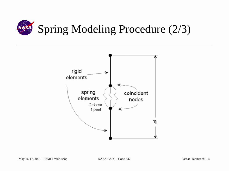
• A fine mesh of grids is created in the mid-plane of the bonded joint.• For every grid in the mid-plane mesh, an initially-coincident grid is
created.• Three springs are placed between each pair of initially-coincident• grids.
– These springs act in the X, Y, and Z directions.* X and Y axes are parallel to the overlap plane of the bonded
joint.* Z axis is defined by the right-hand-rule.
• Rigid elements are used to connect the mid-plane grids to the cornergrids of the plate elements which represent the adherends.
May 16-17, 2001 - FEMCI Workshop NASA/GSFC - Code 542 Farhad Tahmasebi - 4
Spring Modeling Procedure (2/3)

May 16-17, 2001 - FEMCI Workshop NASA/GSFC - Code 542 Farhad Tahmasebi - 5
Spring Modeling Procedure (3/3)

May 16-17, 2001 - FEMCI Workshop NASA/GSFC - Code 542 Farhad Tahmasebi - 6
Spring Stiffness Values (Shear)
γ
δ
ηZ
AAAANoteKK GAV
GAV
AVG
ss
corneredgeinternal 42:
;;
===
=∴=
=∴===
ηδ
ηδγηδτγτ
Symbol Descriptionτ Adhesive shear stressG Adhesive shear modulusγ Adhesive shear strainV Shear forceA Element areaδ Shear deflectionη Adhesive thicknessΚ s Shear spring stiffness
May 16-17, 2001 - FEMCI Workshop NASA/GSFC - Code 542 Farhad Tahmasebi - 7
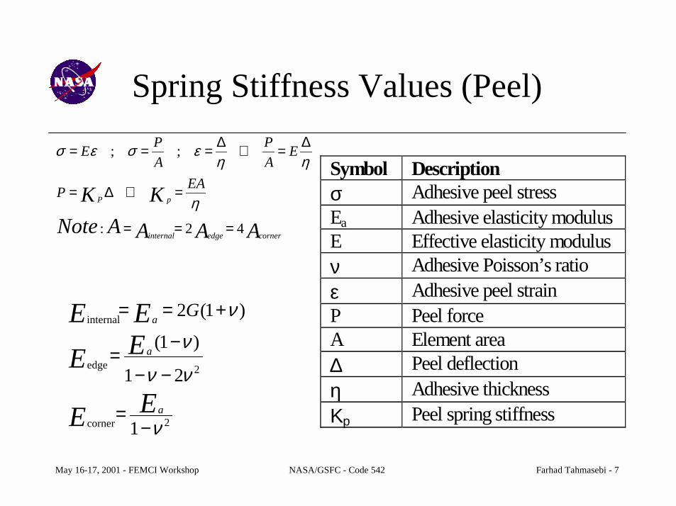
Spring Stiffness Values (Peel)
AAAANoteKK EAP
EAP
APE
pP
corneredgeinternal 42:
;;
===
=∴∆=
∆=∴∆===
η
ηηεσεσ
Symbol Descriptionσ Adhesive peel stressEa Adhesive elasticity modulusE Effective elasticity modulusν Adhesive Poisson’s ratioε Adhesive peel strainP Peel forceA Element area∆ Peel deflectionη Adhesive thicknessΚp Peel spring stiffness2
2
1
21
)1(
)1(2
ν
νν
ν
ν
−=
−−
−=
+==
EE
EEEE
a
a
a G
corner
edge
internal
May 16-17, 2001 - FEMCI Workshop NASA/GSFC - Code 542 Farhad Tahmasebi - 8
Description of the Adhesive StressProgram (1/2)
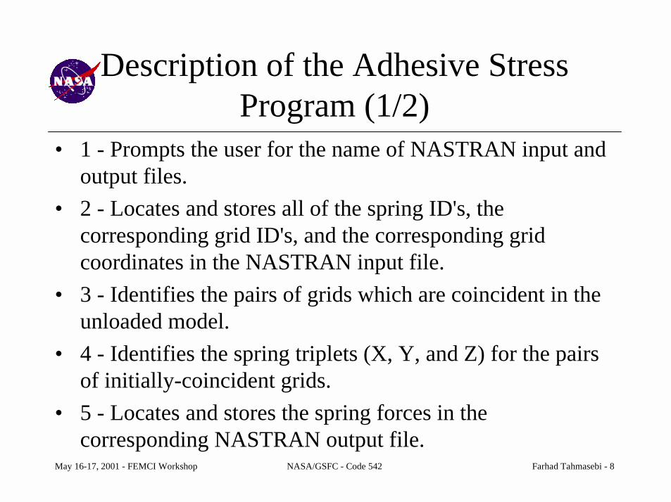
• 1 - Prompts the user for the name of NASTRAN input andoutput files.
• 2 - Locates and stores all of the spring ID's, thecorresponding grid ID's, and the corresponding gridcoordinates in the NASTRAN input file.
• 3 - Identifies the pairs of grids which are coincident in theunloaded model.
• 4 - Identifies the spring triplets (X, Y, and Z) for the pairsof initially-coincident grids.
• 5 - Locates and stores the spring forces in thecorresponding NASTRAN output file.
May 16-17, 2001 - FEMCI Workshop NASA/GSFC - Code 542 Farhad Tahmasebi - 9
Description of the Adhesive StressProgram (2/2)
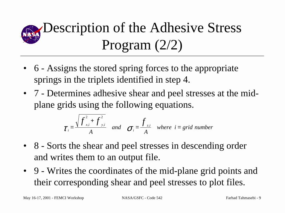
• 6 - Assigns the stored spring forces to the appropriatesprings in the triplets identified in step 4.
• 7 - Determines adhesive shear and peel stresses at the mid-plane grids using the following equations.
• 8 - Sorts the shear and peel stresses in descending orderand writes them to an output file.
• 9 - Writes the coordinates of the mid-plane grid points andtheir corresponding shear and peel stresses to plot files.
numbergridiwhereA
andA
fffiz
iiyix
i ==+
= ,
2
,
2
, στ

May 16-17, 2001 - FEMCI Workshop NASA/GSFC - Code 542 Farhad Tahmasebi - 10
Description of the Adhesive StrainProgram (1/2)
• Starts by executing steps 1 through 4 that the AdhesiveStress program goes through. Next, performs the followingoperations.
• 1 - Locates and stores the mid-plane grid pointdisplacements in the NASTRAN output file.
• 2 - Calculates and stores the adhesive spring deformationsfrom the grid point displacements obtained in the previousstep.
• 3 - Assigns the stored spring deformations to theappropriate elements in the spring triplets corresponding tothe pairs of initially-coincident grids

May 16-17, 2001 - FEMCI Workshop NASA/GSFC - Code 542 Farhad Tahmasebi - 11
Description of the Adhesive StrainProgram (2/2)
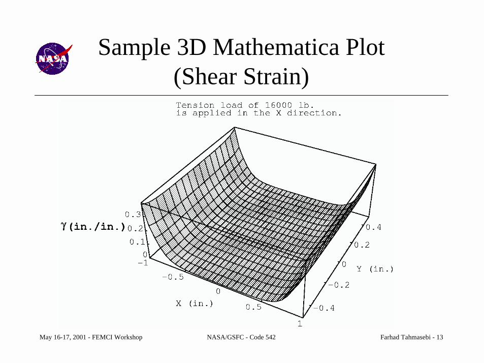
• 4 - Calculates adhesive shear and normal strains at themid-plane grids using the following equations.
• 5 - Sorts the shear and normal strains in descending orderand writes them to an output file.
• 6 - Writes the coordinates of the mid-plane grid points andtheir corresponding shear and normal strains to plot files.
numbergridiwhereand izi
iyix
i==
+=
ηηδεδδγ ,
2
,
2
,

May 16-17, 2001 - FEMCI Workshop NASA/GSFC - Code 542 Farhad Tahmasebi - 12
Inputs & Outputs
• Inputs– NASTRAN input file– NASTRAN output file
* Spring forces* Displacements of the adhesive mid-plane grids
– Element area (adhesive stress program)– Adhesive thickness (adhesive strain program)
• Outputs– .ad_strs (sorted stresses) & .ad_strn (sorted strains) files– .tau, .sigma, .gamma, & .epsilon Mathematica plot files
• The grids and springs can be numbered in any order.
May 16-17, 2001 - FEMCI Workshop NASA/GSFC - Code 542 Farhad Tahmasebi - 13
Sample 3D Mathematica Plot(Shear Strain)

May 16-17, 2001 - FEMCI Workshop NASA/GSFC - Code 542 Farhad Tahmasebi - 14
Sample 3D Mathematica Plot(Shear Stress)

May 16-17, 2001 - FEMCI Workshop NASA/GSFC - Code 542 Farhad Tahmasebi - 15
Sample Output File (.ad_strn)No. of spring grids = 561Grids: 8001 9001 => Gamma= 0.3811, and Epsilon= -0.1195Grids: 8002 9002 => Gamma= 0.2440, and Epsilon= 0.0419Grids: 8003 9003 => Gamma= 0.1677, and Epsilon= 0.0734...******** SORTED SHEAR STRAINS **********Grids: 8033 9033 => Gamma= 0.3848Grids: 8561 9561 => Gamma= 0.3848Grids: 8001 9001 => Gamma= 0.3811...******** SORTED PEEL STRAINS **********Grids: 8099 9099 => Epsilon= 0.1797Grids: 8495 9495 => Epsilon= 0.1797Grids: 8462 9462 => Epsilon= 0.1786...

May 16-17, 2001 - FEMCI Workshop NASA/GSFC - Code 542 Farhad Tahmasebi - 16
Sample Output File (.ad_strs)No. of springs = 1683. No. of points = 561Springs: 4002 5683 5684 => Tau= 17050.4878, and Sigma= 5020.4877Springs: 4005 5685 5686 => Tau= 21762.8052, and Sigma= -3518.7251Springs: 4008 5687 5688 => Tau= 14779.8012, and Sigma= -6167.9155...******** SORTED SHEAR STRESSES **********Springs: 4194 5811 5812 => Tau= 38807.8485Springs: 5580 6735 6736 => Tau= 38807.8485Springs: 5490 6675 6676 => Tau= 38713.2117...******** SORTED PEEL STRESSES **********Springs: 4200 5815 5816 => Sigma= 15544.5325Springs: 5388 6607 6608 => Sigma= 15544.5325Springs: 5289 6541 6542 => Sigma= 15004.5107...
May 16-17, 2001 - FEMCI Workshop NASA/GSFC - Code 542 Farhad Tahmasebi - 17
References
• K.R. Loss and K.T. Keyward, Modeling and Analysis of Peel andShear Stresses in Adhesively Bonded Joints, AIAA paper 84-0913.
• L.J. Hart-Smith, Adhesive-Bonded Double-Lap Joints, TechnicalReport NASA CR112235, Contract NAS1-11234, McDonnellDouglas/Douglas Aircraft Co., Jan. 1973.
• L.J. Hart-Smith, Design Methodology for Bonded-Bolted CompositeJoints, Final Technical Report AFWAL-TR-81-3154, Vol. I, ContractF33615-79-C-3212, McDonnell Douglas/Douglas Aircraft Co., Feb.1982.


![Final Shilpabank Farhad[1]](https://static.fdocuments.in/doc/165x107/577d275b1a28ab4e1ea3b63e/final-shilpabank-farhad1.jpg)


![DSE_5210-5220_US_WEB[1] FARHAD](https://static.fdocuments.in/doc/165x107/577d37551a28ab3a6b956e56/dse5210-5220usweb1-farhad.jpg)