Software Systems Development 9read.pudn.com/downloads95/doc/383714/SSD9... · Web viewSchach,...
309
Software Systems Development 9 Software Specification, Testing, and Maintenance This course is an introduction to software engineering. Software engineering includes the principles and practices that contribute to producing better software and to making software development more predictable and economical. You will learn about how software development practices have changed in the last few decades and about the different phases that a software product goes through. For each phase of software development, you will study specific techniques for improving the quality of products and you will read about the interactions and expectations of groups and organizations that participate in the software development process. - 1 -
Transcript of Software Systems Development 9read.pudn.com/downloads95/doc/383714/SSD9... · Web viewSchach,...
Software Systems Development 9
Software Specification, Testing, and Maintenance
This course is an introduction to software engineering. Software engineering includes the principles and practices that contribute to producing better software and to making software development more predictable and economical. You will learn about how software development practices have changed in the last few decades and about the different phases that a software product goes through. For each phase of software development, you will study specific techniques for improving the quality of products and you will read about the interactions and expectations of groups and organizations that participate in the software development process.
The course is organized into eight units, each with several sections. All units have a multiple-choice quiz and all but the first unit contain a practical exercise. The exercises are part of the project for the course and lead you to create a software product from start to finish. There are also three in-class exams. You can read about how to work through the quizzes, exercises, and exams in the course Help pages.
Prerequisites
SSD4 User-Centered Design and Testing; SSD7 Database Systems
Course Textbook
The required textbook for the course will be:
Schach, Stephen. Object-Oriented and Classical Software Engineering. 6th ed. McGraw Hill Publishing Co., 2004. ISBN: 0-07-286551-2
OR
- 1 -

Schach, Stephen. Object-Oriented and Classical Software Engineering. 5th ed. McGraw Hill Publishing Co., 2002. ISBN: 0-07-239559-1
OR
Schach, Stephen. Classical and Object-Oriented Software Engineering, with UML and Java. 4th ed. WCB/McGraw Hill Publishing Co., 1998. ISBN: 0-07-230226-7.
Previous editions of the book can be used instead of the new sixth edition; copies of older editions may be available through sources that sell used books.
Important: Reading assignments given in the online notes are valid for any edition unless otherwise noted. Where the readings for an edition differ from the default, the page or section numbers are listed in parentheses for the specified edition.
A complete list of SSD9 Required Readings has been compiled for your reference.
Course Outcomes
The purpose of SSD9 is for students to
1. Learn the principles and practices for producing better software and for making software development more predictable and economical
2. Learn to examine critically the different phases of a software product's life cycle
3. Learn various approaches to software design and about the role of software architecture in software design
4. Learn structured systems analysis, object-oriented analysis (OOA), and object-oriented design (OOD)
5. Learn the different types of software testing, documentation, and maintenance techniques
6. Learn to design and build Internet-based software projects of significant scale, acquiring experience in all phases of the software product life cycle
- 2 -
Students successfully completing SSD9 will be able to
I. Produce
1. Software systems based on customer requirements
2. Scope descriptions and requirements checklists by choosing a suitable development model
3. Unified Modeling Language (UML) diagrams illustrating the use cases identified for the software product
4. Use case scenarios for normal and abnormal use cases
5. A class list for a product using the noun extraction technique
6. Class diagrams and state transition diagrams using the UML notation
7. Sequence diagrams and collaboration diagrams using UML
8. Detailed class diagrams, object interface specifications, and skeletal Java class files
9. Detailed code documentation using Javadoc10. Project implementation plans, test plans, and
documents at every phase11. A final software system for demonstration
II. Use
1. OOA and OOD techniques2. Entity-relationship (ER) modeling techniques3. The MySQL database system and Java Database
Connectivity (JDBC) for a project4. Javadoc to produce documentation5. Techniques for improving the quality of artifacts
for each phase of software development
III. Knowledgeably Discuss
1. Specification techniques that address the various software engineering principles
2. Computer-aided software engineering (CASE) technology
- 3 -

3. Code reuse and design reuse4. Managing maintenance: fault reports, fault
prioritization5. Maintenance of object-oriented software
IV. Hold Positions as Software Engineers
Those who certify in this course will be able to (a) develop software systems using modern software engineering principles; (b) make decisions about selecting the appropriate life-cycle model for software development; (c) develop documents required by each life cycle of the software development process; and (d) develop test plans and acceptance test plans for complex software projects.
Unit 1. Overview of Software Engineering
The overall goal of software engineering is the production of fault-free software that satisfies the user's needs and that is delivered on time and within budget.
In this unit, we begin by examining some of the challenges of developing software, and some of the myths that still surround the software development process. We then look back at the evolution of software practices and at the concerns that motivated the shift from a focus on programming to a wider view of software production. Next, we introduce the stages of the software life cycle and consider their economic aspects. The unit concludes with a brief review of some of the terminology that will be used throughout the remainder of the course.
1.1 Software Challenges and Myths 1.2 History and Evolution 1.3 Life Cycle and Economy 1.4 Terminology
Assessments Multiple-Choice Quiz 1
- 4 -

1.1 Software Challenges and Myths
In this module we will briefly survey some of the challenges to be faced when developing software, and some of the misconceptions about software development that have sprung up over the relatively short history of large-scale software production.
Just about anyone who has participated in developing software products of any significant size or complexity will tell you two things. First, if there is something you can count on, it is that it will take you longer to finish than you expect. Second, even when you think the product is completed, problems will still be lurking that testing will not have found. In the old days, people used to say that whatever time estimate you thought was reasonable, you should multiply it at least by a factor of three, or ten. From the perspective of a software development manager, development delays, and errors found after delivery can incur unacceptable losses, which take the form of additional (unexpected) costs and greatly diminished customer satisfaction and confidence. In today's competitive environment, getting a product to market on time and with as few residual "bugs" as possible can mean the difference between the success and failure of a product, or even a company.
Why are the costs of software development so high? In part, because software development frequently goes over the estimated time limits. So why does it take so long to get programs finished? Why do we have difficulty measuring development progress and why can we not find all errors before we deliver? These questions do not have a simple answer because the software process is a complex one, involving multiple parties who have different objectives and constraints. The actors in software production�the customers, managers, and developers�may come into the process with expectations and attitudes that, while seemingly reasonable, can contribute to increasing the time and cost of product development. Some of these expectations and attitudes, although mistaken, are quite widespread that they have acquired a mythical status. We will review some of these myths below. (For additional myths, refer to Pressman 2000, section 1.4.)
Some mistaken perceptions about software development originate with the customer. For example:
- 5 -

"A general statement of objectives is sufficient to begin writing programs�we can fill in the details later."
"Project requirements continually change, but change can be easily accommodated, because software is flexible."
Both of these myths reflect the perception that, because software can be changed more easily than a manufactured product, it can be modified in response to changing requirements at any point in the process, without paying any penalty. While it is true that it is easier to change code than to change a manufactured product, the repercussions of software changes go far beyond the actual change itself. In some cases, the changes will be very localized and minor; in other cases, they may require substantial redesign of the affected component, as well as interacting components. In all cases, any change will require substantial testing to make sure that no new problems have been inadvertently introduced.
Some of the misconceptions about software development come from the developers themselves. For example:
"Once we write the program and get it to work, our job is done." "The only deliverable for a successful project is the working program." "Until I get the program running, I really have no way of assessing its quality."
While it is true that a working program is an essential component of successful software development, it is by no means the only component. Depending on what agreements have been reached for maintaining the software after delivery, either the developer or the customer will need to make some modifications to the code. At that point, it will be extremely important to have code that is clearly written and well documented, since it is very likely that the programmers making the modifications will not be the same ones who wrote the code initially. Even if the programmers were the same, they would quickly find out how much they had forgotten about their own programs! When it comes to assessing the quality of the program as well as its ultimate correctness, other factors come into play. For example, we may ask whether the assumptions made by each piece of the code are well defined, or whether a complete test suite has been provided for the program, or for individual components of the program. Being able to answer these questions positively will not only result in a program that is easier to maintain, but will also help the programmer build confidence in the building blocks of the system and assess its quality during
- 6 -

development. Formal software reviews that look at these aspects of the software will also help to assess its quality.
Finally, some of the myths surrounding the need for software engineering may come from the management of the organization where the product is being developed. Consider the following statements coming from a manager and, immediately following them in each case, some objections that should be raised:
"We already have a book full of standards and procedures."
Any manager working in an organization whose daily running already requires adherence to a number of standards and procedures is, understandably, reluctant to add more. Yet those existing standards and procedures may have little impact on the quality of the software process; perhaps they are outdated and do not reflect current practices, or perhaps they are simply not applied.
"My people have state-of-the-art software development tools, because we bought them the newest computers."
Hardware by itself contributes relatively little to high-quality software development; it is more important to have good software tools and well-defined development practices.
"If we get behind schedule, we can just add more programmers."
Today's computers can run very large software products that would take a single person a long time to develop. Although team programming permits the development of large products in a short time by allowing work in parallel, it also introduces complexity. Changes affecting the interface to modules of the system need to be distributed among all programmers whose code interacts with those modules. Coordination among team members may require lengthy meetings and conferences. When adding new programmers to an ongoing project, one must consider the time that it will take the new programmers to get up to speed and become productive, and the time required for existing team members to train the newcomers, as well as any additional time required for communication and coordination within the enlarged group.
While trying to debunk individual myths surrounding software development may be useful in itself, the real solution for meeting the challenges of software production is to provide a framework that supports constant, evolutionary improvement in product and process, based on an explicit model of the development process. In Unit 2, we will examine some of the models that have already been developed.
- 7 -

At the very beginning of this unit, we defined software engineering rather generally as "a discipline whose aim is the production of fault-free software that satisfies the user's needs and that is delivered on time and within budget." More specifically, software engineering is an endeavor whose objective is to set realistic expectations regarding the software development process, so these expectations can be satisfied. It achieves its objective by planning for and tracking a development itinerary where the functionality of a product matches its requirements, the development schedule satisfies the constraints of both the customer and the developer, and the overall cost of development does not exceed the budget provided for it. Knowing how to analyze and manipulate the trade-offs between what the customer wants and what the software producer can provide under the given constraints is what separates a system engineer from a mere programmer. From the software engineering point of view, actual coding is a small part of the overall effort!
Finally, in the midst of hardware, software, schedules, and budgets, one should not forget that, like many other enterprises, software production involves human beings�the customers, the programmers, and the managers�and therefore software engineering is directly concerned with managing people and facilitating communication.
References
Pressman, Roger S. Software Engineering: A Practitioner's Approach. 4th ed. New York: McGraw Hill, 2000.
1.2 History and Evolution
The goal of this module is to provide a brief history of software development, by considering the evolution of software practices since the 1950s. The growing complexity of software applications, together with the lessons learned from early software projects, have made software engineering increasingly important in today's use case.
- 8 -
Readings:
Schach, section 1.1.
In the 1950s and through much of the 1960s, hardware dominated the computer world. Several years after the invention of the transistor in 1947, computers began scaling down in size and cost. In 1954, IBM announced its first transistor-based computer and by the late 1950s several organizations, companies, and universities had computers at their disposal. At that time, computers were still very expensive and very large: a computer significantly less powerful than today's laptop occupied as much as one or two rooms, together with permanent storage devices and other accessories. Management of computer production was substantially hardware oriented, and many of the same practices applicable to the manufacturing of industrial products�formal standards, quality controls, and cost controls�were applied to hardware. There was an area of expertise called hardware engineering, but the software itself was still something of an afterthought.
With so much attention and capital going into hardware, software production and programming was the purview of a few individuals who understood how to make all that machinery do something useful. They worked with programming languages (like assembly language) that few programmers would choose to use today. Programming was definitely seen as more of an art than a science, and had little visibility at the management level.
Programmers were given complete responsibility for the software, and it was common for a programmer to begin coding without spending any time on analysis, specification, or design. This approach led to an undisciplined style of programming, following few if any formal methods and learning by trial and error. There was a lack of predictability in the quality of the code, and a lack of accountability on the part of its developers. It was difficult if not impossible to estimate how long a project would take. Furthermore, the code was often poorly and incompletely documented causing a severe problem for anyone taking over its maintenance from the original developers.
As computers became more widespread through the late 1960s and 1970s, the number of people and organizations relying on hardware and software mushroomed, and the disorderly world of software development was destined for reform. In the literature, one finds
- 9 -

references to the "software crisis" of the 1970s, an era when the quality of software was generally unacceptably low, deadlines were seldom if ever met, and costs sometimes went over budget to a significant degree. The costs of software development began to overshadow the costs associated with hardware. It was clearly time to replace the old CABTAB ("code a bit, test a bit . . . don't know how long it will take") approach to programming, which had become too costly, with a new one that emphasized formal methods for quality assessment and cost control.
Efforts from the 1970s through the 1990s focused on increasing understanding of the science of programming, improving predictability of the software product and process, and improving the accountability of the participants. The software development process became a primary object of study for research and development, especially at newly founded research institutions like Carnegie Mellon University's Software Engineering Institute (http://www.sei.cmu.edu). Still, the problems of the original "software crisis" have not been completely alleviated, and the effectiveness of software development is still poor in many fields. Stephen Schach suggests in his textbook that the "software crisis" should have been called the "software depression," because it has lasted significantly longer than a crisis normally does. Today software has become ubiquitous and its quality is even more crucial. It drives business decisions. It serves as the basis for solutions to science and engineering problems. It is heavily relied upon by transportation and telecommunication systems, by the medical, industrial, and military establishments, and by the ever-growing entertainment industry. Therefore, it is even more vital now to improve the predictability of the software process in terms of cost, time, and correctness.
The term "software engineering" was coined in 1967 and formally endorsed the following year by the NATO Software Engineering Conference, held in Germany. It reflected the hope that software could be designed, implemented, and managed like products in other engineering disciplines, for example like road bridges in civil engineering. We do not build road bridges using trial-and-error methods, because the costs are too high, in terms of both money and safety. So why do we build software that way? The bridge analogy is beneficial in some ways. It points out that, in the case of products like bridges, the designers make their best effort to anticipate different conditions and problems resulting from them. Consequently, the product is designed to avoid total failure and to
- 10 -

withstand problem conditions by designing for them and building in a margin of safety. But the analogy with bridges, like most analogies, breaks down in certain respects. In the first place, the analogy is not always applicable to all software systems. For example, when using rapid prototyping as part of the development strategy, the prototype is not expected to be robust.
Even in many finished applications, software failure�either a crash or an incorrect result�is not as catastrophic as the failure of a bridge structure, because a program can be easily restarted but a bridge cannot be rebuilt quickly or easily. The program can be reinitialized or its state recovered, if it was periodically saved, with relatively little cost. On the other hand, problems that do not lead to a crash can be more insidious. Errors may accumulate over time, causing the internal state of the system to deteriorate over a long while. By the time a failure occurs, understanding the primary cause of the fault can be difficult. In contrast, signs of impending failure, such as a crack, may be more obvious in a frequently inspected bridge. Moreover, fault tolerance and failure avoidance in a software system will necessarily take a different form than in a physical structure. For example, you cannot exactly guarantee safety by over-designing the software the same way an engineer designs a bridge for heavier-than-expected loads. Detection of and recovery from faults is likely to be implemented by embedding consistency and assumption checks in the program, and by providing error reports and recovery options before a situation is reached that leads to a system crash (for example, executing code that attempts to divide a number by 0).
Another important way in which software engineering differs from civil engineering is in the maintenance of systems. Due to the changing requirements imposed by the environment in which it is used, software is incrementally redesigned and re-implemented throughout its lifetime, while bridge maintenance is typically very minor and localized. The kinds of changes that software goes through in its lifetime as part of maintenance are far more radical than those bridges are expected to go through. Bridges may need to be rebuilt every so often to accommodate more traffic and heavier loads or due to address physical deterioration, but there are bridges that have lasted with little maintenance for hundreds of years! In contrast, a software product may have a very short lifetime before it reaches obsolescence or before it becomes more costly to maintain than replace.
- 11 -

Finally, unlike bridge building, the experience accumulated in developing software will not necessarily result in better software because the hardware platforms and associated operating systems are changing and becoming complex at a faster rate than we can master them. This acceleration is partly due to the quantum leaps made by hardware technology in the last half-century, as well as the changes in the capabilities of our software tools.
The following module will introduce the stages of the software life cycle and will consider their economic aspects. Both topics will be investigated in significantly more detail in the remaining units of the course. Although this course focuses on the general principles of software engineering, it is important to know that the application of these principles can vary significantly from project to project, depending on factors such as programming language, type of software, and development methodology. For example, the distinction between specification and design, which is very clear-cut for structured programming languages, is much less distinct for object-oriented languages where the discussion of objects begins during the specification phase. In Unit 4, you will learn more about the differences between object-oriented and traditional approaches to software development.
1.3 Life Cycle and Economy
The goal of this module is to introduce the overall software life cycle, and to introduce economic factors that influence both the choice of a development approach and overall constraints on development itself.
Readings:
Schach (4th Edition), sections 1.2–1.6. Schach (5th Edition), sections 1.2–1.6.
Schach (6th Edition), sections 1.2–1.10.
There are many ways to write programs that produce a set of desired output from a specified set of input. The goal of software
- 12 -

engineering is to find the development methodology that is optimal, where optimality might be evaluated along several different dimensions according to the situation. Factors like development time, development cost, product quality, maintainability, and so on are all considered when deciding on an optimal development methodology.
For example, suppose the FastWeb company decides to develop a program that will convert a set of documents to HTML format. If this job is to be done once, by internal staff only, it might make sense to select a development methodology that minimizes cost and time, at the possible expense of quality. It is okay if the software crashes once in a while, because external customers will never use it. On the other hand, if the conversion program will become part of FastWeb's suite of support tools for external customers, quality and maintainability are much more important; in this case, a development methodology that produces software that is more reliable may be considered optimal�even if it takes more time and money.
Any model of software development must take into consideration that the software goes through several different phases in its lifetime. These are sometimes given different names and the tasks of the different phases are sometimes grouped together differently, but all software development involves these basic activities: requirements analysis, specification, design, implementation, integration, maintenance, and retirement.
Requirements analysis: The developer meets with the customer to understand the problem to be addressed by the proposed software system. Together, they explore and refine the concept through an interview process, where the client's specific requirements and constraints are identified and discussed. The result of the requirements analysis phase is a requirements document or checklist.
Specification: Using the requirements document as a guide, the developer produces a specification for all of the functionality to be included in the product, along with a development methodology and estimated cost and schedule.
Design: Using the functional specification as a guide, the developer produces detailed design documents for the individual software modules to be built, and the overall software architecture that will integrate those modules and interface with the customer's software environment.
- 13 -

Implementation: Following the design documents and the guidelines laid down in the project plan, the developer programmers construct the individual software modules. This phase ends when all the modules have been implemented and tested independently.
Integration: The individual modules are combined into the overall software architecture, which is then tested by both the developer and the customer. This phase ends when various customer acceptance tests (related to functional requirements) are successful, and the software is deployed at the customer site.
Maintenance: After acceptance of the original product, all changes to the software are considered part of the maintenance process. Types of maintenance include:
o Corrective maintenance, which removes residual faults with no change in original specifications
o Enhancements or updates, which imply changes to the original specifications and new development
o Perfective maintenance, which improves the performance of existing functionality
o Adaptive maintenance, which includes changes made when the product must operate in a new software environment
Note: It is important to note that all software undergoes maintenance, not just bad software. Software must constantly adapt to changes in the functional requirements and operating environments of the organizations using it. Maintenance typically absorbs the majority of the cost and time invested in a software product.
Retirement: When the software is finally taken out of service, it is considered retired. Unless the functionality supported by the software becomes obsolete, retirement usually involves exporting some existing data to one or more new applications before the software is taken out of service. The decision to replace old software with new software is based on a variety of factors, which include the following:
o The immediate cost of the new technology versus the old (the purchase price of the product)
o The cost of developing and maintaining applications that use the new technology o The effort to train staff who will use the new software o The short-term loss of overall productivity during training and familiarization
Note: Software can be retired and replaced in a variety of situations. Sometimes an organization has no choice but to replace existing software and the costs involved are mandatory (as in the case of obsolete software
- 14 -

exhibiting the Y2K bug). In other cases, the long-term costs of using new software are lower than the costs of using the existing software, but it is important to note that it may take some time before the short-term costs of replacement are recuperated.
These phases are usually part of a global project plan that indicates how each of these phases will be carried out. The project plan includes an overall schedule (including activities and milestones), and possibly other forms of global documentation (such as a risk management plan, a test plan, an integration plan, etc.). In Unit 2, we will see that some life-cycle models emphasize an approach where each phase can and should be undertaken more than once�in an iterative or cyclic fashion. This is often necessary when certain aspects of the requirements, design, etc. are not well understood until after some software has already been constructed.
The basic phases presented above have evolved as part of what is referred to as "classical" software engineering, which focuses on the construction of structured programs. Specific code modules, programming languages, etc. are not actively considered until after the specifications phase has ended. On the other hand, developers using the object-oriented approach often explicitly consider reusing existing code objects during the analysis and specification phases. It is important to note that the boundaries of the different phases are fluid; depending on the life-cycle model and implementation approach, different tasks may fall under different phases, and the phases themselves may be arranged in different groupings and/or orderings of tasks. We will learn more about these variations in Unit 2.
Table 1 (below) illustrates the comparative time and effort spent during each of the life-cycle phases (the percentages given are not hard and fast guidelines for every software project, but indicative of the comparative size of the phases, on average). Surprisingly, perhaps, the most time is not spent in the original coding of the modules, but in maintenance activities after delivery. This is especially true of software that remains in service for long periods of time, that typically undergoes several revisions to accommodate changing requirements and changes in the operating environment, integration with other software, etc.
Table 1. Relative Time, Cost of Life-Cycle Phases
- 15 -

Phase Costs Time
Requirements 2% 21% / 18% (and specifications)
Specifications 5% included in requirements
Design 6% 18% / 19%
Module coding 5% 36% / 34% (and testing)
Module testing 7% included in coding
Integration 8% 24% / 29%
Maintenance 67% —
Source: Schach (4th Edition), Figures 1.2 and 1.3 or Schach (5th Edition), Figures 1.2 and 1.3 or Schach (6th Edition), Figures 1.3 and 1.4. The first set of time percentages is an average of various projects from 1976 to 1981. The second set of time percentages is drawn from 132 more recent Hewlett-Packard projects. NOTE: The first set of percentages for time does not add up to 100 in the original table.
One important implication is that any design element, testing technique, or support tool that significantly improves extensibility of the software (and/or reduces the time required to update and test it) will have a greater overall impact on project cost than corresponding technical breakthroughs on the coding process. A good software engineer will consider the various elements of a possible maintenance plan, and will consider optimizing the design and implementation of the system to promote straightforward, low-cost maintenance.
Another characteristic of software engineering is that the coding phase is preceded by significant preparatory activities (requirements, specification, and design) and followed by significant delivery-oriented activities (testing, integration). While over 30% of the average project budget is spent on preparation and delivery, only 5% is typically spent on coding. There are two reasons for this. The first is that quality software delivery depends crucially on a significant investment in these non-coding activities. The second is that the actual time spent coding up the system can be dramatically reduced if detailed specifications and designs have been created in advance. Before the advent of software engineering techniques, coding took much longer because the details of the requirements and design were discovered during implementation. Since changes in requirements and design can imply significant rewriting of existing code, the coding phase takes much longer when adequate
- 16 -

time is not taken to write good specifications and design documentation.
As noted in Schach, section 1.4, more errors are introduced in the specification and design phases than in later phases of the life cycle. Hence, it is important that quality assurance activities begin early, even before coding begins! Although specification and design documents can't be tested the way software is tested, they can be discussed and evaluated in formal reviews, which aim to identify various faults that must be rectified before implementation begins (the details of the review process will be explored in Unit 2).
As mentioned above, the overall cost of finding faults increases exponentially in the later stages of the software life cycle. Since all of the previously completed phases may require significant revision or replacement when a fault is discovered, it is much more cost effective to identify faults as early as possible in the life cycle. In later phases of the software cycle, more people and artifacts are affected by software changes. Previously implemented software must be edited, recompiled, and tested to verify that changes are successful and that no other errors were introduced. Documentation must be updated. Moreover, if the software has already been delivered, a new version of the entire product must be delivered and installed. Given the importance of identifying problems as early as possible, Unit 2 will focus on a set of techniques for specifications and design that help to identify faults early in the life cycle before the process of fixing faults becomes expensive.
Each step or phase in the life cycle can be discussed with respect to its three main components:
Process: the distinct yet interdependent tasks carried out during the phase Methods: the specific task descriptions for each of the tasks in the process Tools: semi- or fully automated support tools for the process and methods
Successful software engineering promotes high quality in all aspects of the process, the methods, and the tools. Although substantial planning is required to pin down all the details of process, methods, and tools for a given phase, a detailed plan is an absolute prerequisite for accurate cost estimation, resource allocation, and scheduling.
- 17 -

1.4 Terminology
Readings:
Schach (4th Edition), sections 1.7 and 2.1. Schach (5th Edition), sections 1.7 and 2.1.
Schach (6th Edition), sections 1.11
In this module, we present and explain some of the key terms in software engineering.
A product is any nontrivial piece of software. A system is the combination of hardware and software that runs the product. A methodology or paradigm is a particular approach, or set of techniques, designed to
accomplish a specific phase or a number of phases in the software development life cycle. A bug is the colloquial term used to refer to a software fault. Although this term is
commonly used by programmers and users, it is important to break the notion down more formally into three terms with different meanings:
A fault is the actual problem in the code that is causing a failure. A failure is the behavior perceived by the user that results from the fault in the
code. An error is the programmer's mistake that led to the fault in the code.
To elaborate on the distinction between the last three terms above with an example, an error might occur when the programmer forgets to copy the latest version of a Java class file to the directory from which the product is assembled in preparation for delivery. In this case, the fault might be that the product throws an unknown method exception and terminates. The observed failure might be that the system freezes when the user clicks on the "Save" button in the product's user interface. This example, though simple, illustrates how difficult it can be to uncover the error from the observed failure.
More terminology will be introduced in later modules as required.
One more group of terms whose meaning requires some elaboration concerns the three main participants in the software development process:
The client�the individual or organization who wants a product to be developed The developer�the individual or group responsible for building the product
- 18 -

The user(s)�the person or persons who will utilize the product and on whose behalf the client has commissioned the product
The roles of client, developer, and user may be filled in different ways. Sometimes the client and the user are the same individual or organization, and the developer is some outside party contracted to build the software. For example, a hospital may contract a company specializing in medical support software to build a specialized database system that stores patient records or that keeps a running record of the vital signs of a patient who has just undergone surgery. Hospital management is the client; medical and nursing staff will be the users. For smaller software projects, the developer may be an individual rather than an organization. At other times, all three roles may be filled by groups inside the same organization. For example, the translation department of a large machinery manufacturer may request the computer department to develop specialized software to assist in producing and reusing translations of technical documents.
The first example above, in which the client and the developer are completely separate organizations, is an instance of contract software development. The second example, in which the client and the developer are part of the same organization, is an instance of internal software development. A third situation occurs when the software product is being developed by a company or individual in response to a perceived market need. In this case, the client could be identified with the management of the company, the developer with the technical division of the company, and the user with the potential customer for the product. Other variations on the distribution of roles are also possible. As different as these situations are, they will all benefit from careful specification, design, planning, testing, and maintenance of the software product.
Unit 2. Software Life Cycle
In this unit, you will cover the different stages of the software life cycle in a bit more detail and you will read about specific life-cycle models for software development.
2.1 Overview of the Life Cycle
- 19 -

2.2 Life-Cycle Methodologies
Assessments Exercise 1 Multiple-Choice Quiz 2
2.1 Overview of the Life Cycle
In this module, we will review and examine in some detail the different phases of a software product's lifecycle. Further detail about specific methodologies to apply in each phase is contained in later units of the course.
Readings:
Schach (6th Edition), sections 3.1-3.2. 2.1.1 Problem Identification and Scope 2.1.2 Requirements Analysis and Specification 2.1.3 System Design 2.1.4 Implementation 2.1.5 Testing and Delivery 2.1.6 Maintenance
2.1.1 Problem Identification and Scope
Statement of Scope
The decision to develop a new software system, either internally or via external contracting is typically justified when some important requirement of the organization is not currently being met. Perhaps there is no software currently supporting certain crucial activities. Maybe some existing software has become obsolete and is no longer able to perform effectively the tasks it was designed to do. Perhaps the requirements of the task itself have changed. When making a decision to develop (or purchase) new software, it is essential to first understand the problem well, to verify that a software solution is appropriate, and to confirm that there are not other (possibly simpler and cheaper) ways to address the problem.
- 20 -

Consider, for example, the case of a restaurant starting out as a small family-run business. Initially, with only a few tables, limited clientele, and short operating hours, the accounting books are kept on paper manually. As the business expands, the owners realize that they are starting to spend too much time balancing the books and making sure that expenses and income from patrons are logged. At that point, they may find it sufficient to purchase a computer with a small, off-the-shelf accounting package. However, suppose that the business keeps growing, requiring much more floor space and acquiring many more customers. On the one hand, it is becoming a real success—the customers love the food and keep coming back for more. On the other hand, customers begin complaining that it takes too long to process their orders, and too often, they find out, some time later, that the restaurant has run out of what they ordered. The restaurant management decides that they would like a hardware/software product that in addition to balancing the books, allows the waiters to key in the orders and send the order to the kitchen right at the table, so customers will know immediately whether their choice is available. One advantage of this proposed system, the reasoning goes, is that it also keeps track of what customers want, helping the management make better decisions about menu planning, including the quantities of different foodstuffs to have on hand. Another advantage is that as each order is placed, the inventory of basic food ingredients can be automatically updated, making it easier for the management to make daily purchasing decisions.
The solution that the restaurant management chooses may result in a very fancy order and inventory management system, but it is likely to require a significant financial investment, some amount of personnel training, and an increased budget for equipment maintenance. It is possible that the original problem with customer dissatisfaction can be solved much more simply by adding waiters, or giving them radios to communicate customer orders back to the kitchen. The inventory update problem might be solved by connecting the cash register with an inventory management software package, allowing dynamic inventory update based on each new order.
The first part of problem identification, therefore, is to define the problem as precisely as possible and consider a range of solutions and their associated costs. This analysis is essential in determining the viability of a decision to build new software. Another aspect of problem identification is determining the scope of a solution. For
- 21 -

example, if an organization decides that they must have custom-built software, does the resulting software product need to be implemented for different hardware platforms, or is the organization's computing base homogeneous, a group, for example, of only PC-compatible machines? Depending on the type of software application desired, developing for one or more hardware platforms may require significantly different levels of investment.
The responsibility for problem identification usually rests with the client, but the software engineer must be sensitive to mismatches between the problem as described by the client and the solution the client believes to be appropriate. While no software developer wants to refuse a contract, it is not a good idea in the end to build and sell a product that will not adequately address the customer's problem.
Statement of Scope
An effective strategy for balancing the perspectives of both customers and engineers is to write a formal statement of scope. A typical scope statement might include:
Preliminary requirements checklist: The preliminary requirements checklist is typically a brief summary of all the primary functionality the customer requires from the software (for example, "The software must support online ordering of products from our Web site"; "The software must generate monthly ordering statistics sorted by product and geographic area"; etc.).
Customer scope constraints: The customer's idea of scope is typically phrased in terms of constraints that identify minimal expectations for the operation of the software (for example, "The software must handle at least 100 transactions per minute"; "The software must run on Windows NT4.0"; etc.).
Developer scope constraints: There may be a wide range of software solutions that satisfy the preliminary functional requirements and customer scope constraints. It is in the developer's best interest to propose the simplest solution with these characteristics, because it will typically be the most cost-effective system for the customer. On the other hand, it is important for the developer to delimit the functionality of the proposed system. By defining what will and will not be included, one can keep the customer from feeling cheated if software requirements become more demanding after the project is started or after the software is delivered. Additional scope constraints are placed on the software in order to identify the maximal expectations placed on the final product (for example, "The software will be designed to handle a maximum of 100 transactions per minute"; "The software will only be guaranteed to run under Windows NT4.0"; etc.).
- 22 -

A well-written scope statement is the most precise way to specify the problem to be solved, along with the characteristics of the possible software solution(s) to the problem.
2.1.2 Requirements Analysis and Specification
Requirements Analysis Phase Specification Phase Software Project Management Plan (SPMP)
Readings:
Schach (4th Edition), sections 2.2, 2.3, and 9.1. Remark: As an optional reading, chapter 9, discusses prototyping more fully.
Schach (5th Edition), sections 2.2, 2.3, and 10.1. Remark: As an optional reading, chapter 10, discusses prototyping more fully.
Schach (6th Edition), sections 3.3-3.4, 10.1-10.4. Remark: As an optional reading, chapter 10, discusses prototyping more fully.
After the client and the developer have agreed on the general goals of the software development effort, the next step is to determine more precisely the requirements that the software product must satisfy, and to specify the expected input and output of the system in detail. The requirements and specification phases must be completed before detailed design can begin, and certainly, before any coding is attempted. In the case of object-oriented design, an analysis of the characteristics of the required software objects may begin as early as the specifications phase, even though "objects" are also considered part of the design and implementation phases. The differences between these two kinds of analysis will be discussed more fully in 4.1.1 Object-Oriented vs. Structured Analysis.
Requirements Analysis Phase
The requirements phase is of great importance to the success of a software project. Unfortunately, requirements phase is often carried out incompletely or else neglected altogether. During the requirements phase, the client and developer must determine exactly what functionality the software must have in order to meet the customer's requirements. They must also negotiate important constraints, constraints like limitations on development cost, major
- 23 -

deadlines that the project must respect, the performance and reliability expected of the system, and any other constraints imposed by the hardware and operating system.
A precise definition of software requirements (that is, the desired functionality) may be one of the most difficult aspects of the requirements phase. The client may not be able to articulate in a clear and precise manner what the software needs are. The developer may need a variety of techniques to use to elicit the client's real requirements. Traditional methods for eliciting requirements include structured and unstructured interviews, questionnaires, and examination of the process that the client is trying to automate.
In structured interviews, the developer asks preplanned, close-ended questions—questions for which a particular form of answer is desired. For example, the developer might ask how many people will be using the system at the same time or what kinds of data input the system will need to process. To gain a better understanding of how the client will use the software product, the developer may also engage the end users of the product in interviews that are more informal. In an unstructured interview, the developer asks open-ended questions. For example, the developer might ask users to describe the tasks they will perform and the way they normally process information.
Less direct but potentially very informative ways of learning about the process that the software product will support include examining forms used to process information, spending time observing the users as they perform their normal activities in order to understand the nature of the task, and recording those activities with a video camera. Observation and recording can be perceived as intrusions, so this method should be discussed with the client and the users. Note that it is quite common for the "client" and the "user" to be different individuals belonging to the same organization. In discussions with the developer, the "client" is often represented by technical management personnel, but the real day-in-day-out "users" of the software are likely to be other members of the staff. It is important to talk to the users in order to understand their tasks in detail, and to discern whether the proposed functional requirements will result in a software product that meets their needs.
- 24 -

An alternative (and complementary) method for requirements definition is to perform rapid prototyping. A rapid prototype is a piece of software that is developed quickly to demonstrate the visible aspects of desired functionality. Robustness and error handling are typically not present in a rapid prototype and much of the internal computation may be simulated or left out. For example, if the major aspect of a software product is the interface it will present to the users, it may be sufficient to "mock-up" an interface using a graphical user interface (GUI) toolkit, without actually writing any application code. Rapid prototyping is a particularly good approach to take when the client is not able to give the developer a clear idea of how the software should operate. By building a rapid prototype, the developer provides the client with a concrete proposal based on the information the client can offer. The prototype can then serve as a focus for discussing, modifying, and refining ideas further. Under the rapid prototyping approach, several prototype systems may be built before the client is satisfied that the prototype reflects his or her needs; when agreement is reached, the requirements for the actual software product can be derived from the final prototype.
Once the requirements have been made explicit, through elicitation and/or rapid prototyping, the developer can assess the technical feasibility of the proposed software and provide cost estimates. It may turn out that it is technically impossible to achieve the stated objectives, or that it is practically impossible within the time and financial constraints imposed by the client. Any perceived gaps between the required functionality and the feasibility assessment are cause for further discussion and refinement or even for a decision not to proceed at all, if the requirements and constraints cannot be changed.
The requirements for a software product, whether embodied in a rapid prototype or a requirements document, should undergo thorough testing before the requirements phase is left behind. The development organization's software quality assurance (SQA) group should verify that the prototype and/or the requirements document are completely satisfactory to both client and user, before these documents become the basis for a more detailed specification. Unfortunately, the existence of an approved requirements document will not prevent the client from trying to change the requirements later, but such a document does provide a precise statement regarding the software that the developer is under contract to develop.
- 25 -
We will be taking a closer look at rapid prototyping in 2.2.3 Rapid Prototyping Model.
Specification Phase
The ultimate goal of the specification phase, which is sometimes also called the system analysis phase, is to model the desired software product. We build models of the data the system must process (data dictionaries and entity relationship models), models of the transmission of data among different components (data flow analysis), and models of the flow of control from component to component based on the state of the system (control flow analysis). Different techniques, many of them graphical (data flow diagrams, for example), are used for specifying the various aspects of the product. It is important to note that these models and techniques, which will be discussed in Unit 3, specify what the system must do and not how it does it. The how is the purview of the design phase, which will be described next in 2.1.3 System Design.
The goal of the specification phase is to transform the general requirements for a software product into a concrete document describing what the system will and will not do: this document to be produced is called the specification document, or simply the specifications. The specification document describes the functionality of the system, makes explicit the constraints the system must satisfy (speed or maximum error rate, for example), and specifies the expected input and corresponding output. The input-output specifications should include a description of how the system should respond to unexpected and erroneous input. In addition, the specifications document may include acceptance criteria. These may just be a restatement of the constraints and input-output behavior, or a set of tests that a system must pass. For example, in the case of a system designed to translate between English and other languages, the acceptance criteria could stipulate that the system will be accepted if it translates correctly 90% of the sentences contained in texts that have not been used previously during development and testing.
The specification document functions as a legal contract. The developer will consider the contract completed when it delivers a software product that satisfies the acceptance criteria set out in the specifications. To avoid complications and disagreements about whether or not a delivered product meets specifications, the
- 26 -
specification document should be carefully checked for the following problems:
Vagueness of the language: The document should not use terms that are not or cannot be defined precisely. These include such obviously vague terms as "ample memory" or "sufficient speed," as well as terms that sound precise but are not, like "optimal speed" or "98% complete."
Ambiguity of the language: The document should be checked for statements that can be interpreted in more than one way. Consider the following: "The interface module will call the arithmetic module. If the module receives erroneous input, it will signal an error to the error handler." The phrase "the module" in the second sentence can refer to either the interface module or the arithmetic module.
Incompleteness of the specifications: Common types of omissions include failure to consider all legal values of an input, failure to specify system behavior under unexpected or incorrect input, and failure to consider all possible combinations of input when a system makes decisions based on multiple inputs.
Inconsistency of the specifications: In the specification document for a large system, it is possible that the same situation arises in more than one context, and it is easy to specify different behaviors for that situation in different places of the document. For example, the specification document for a database interface system might say that when the data in an entry form is committed, errors in any of the data areas of the form will prevent the commit process from completing successfully. Elsewhere in the document, it might say that each field in the data entry form is individually checked for incorrect values when the cursor leaves the field, and that no further action is permitted until the error is rectified. In a subtle way, these statements are inconsistent or contradictory, because if the second statement is true and the user enters an incorrect value, then the interface should not even allow the user to request a commit action.
Like the requirements document, the specifications document must be carefully examined by the developer's SQA group, as well as the specification team and the client, before it is approved and used as the basis for further work. In addition to checking for problems such as vagueness, ambiguity, incompleteness, and inconsistency, the SQA group should determine the feasibility of the specifications based on information provided by the client. A very desirable characteristic of the specification document is traceability, that is, the ability to trace every one of its statements to something the client said during the requirements phase. Ideally, it should be possible to link each statement in the specification document either to a statement in the requirements document or to the rapid prototype from which requirements were derived. A formal review process, in which developer and client teams go through the entire document systematically, is a good way of formally testing the
- 27 -

specifications. We will describe different ways of performing formal document reviews in Unit 6.
Software Project Management Plan
It is only after the specifications have been completed and reviewed that detailed planning can begin. With a thorough understanding of the software to be built, the developer can provide firm estimates of how much time and money it will take to complete the product. The detailed plan for development of the software, called the software project management plan (SPMP) includes the personnel that must be assigned to different phases of development, the deliverables (what the client will actually get), the milestones (when the client will get them), and the budget (what it will cost). If the developer needs the client to provide specific types of information or files during the development process, the time when these will be made available should also be specified in the plan. The cost and the duration of the project must be considered and negotiated carefully. The developer must be reasonably sure that it is feasible to develop the product within the allotted time and budget, or run the risk of losing money and credibility. At the same time, the developer should not try to inflate excessively the estimates of time and cost, since this might only prompt the client, especially an external client, to find another contractor who can do it faster and cheaper.
We will also return to different ways of specifying software in Unit 3. Analysis and Specification.
2.1.3 System Design
If the goal of the specification phase is to spell out what the product will do, the goal of the design phase is to determine how it will do it.
Readings:
Schach (4th Edition), section 2.4. Schach (5th Edition), section 2.4.
Schach (6th Edition), section 3.5.
The design team uses the specification document to determine the internal structure and operation of the software product. The objectives of the design phase, therefore, include:
- 28 -

Choosing the data structures that will represent the information manipulated by the program
Choosing the algorithms that will operate on and manipulate the data structures Determining the internal data flows, that is, how the information will move from
component to component of the program Breaking the product into modules, or self-contained pieces of code that interact with
other modules in the product through a well-defined interface Designing the interface for each module
The output of the design phase consists of two documents. The architectural design document describes the structure of the system in terms of modules, their interfaces, and their interactions (the data flow). The process of breaking a software product into smaller independent modules is called modular decomposition. The second design document, the detailed design, gives a description of each module, including the data structures and algorithms to be used. It specifies and guides the programmers' task during the implementation phase.
In developing a design, the design team will need to balance off considerations such as generality and complexity, anticipate how the design can handle future enhancements, and as much as possible, try to design for maintainability and future reusability of the software. While it is almost guaranteed that new requirements for the product will surface as soon as the product is delivered, if not earlier, it is usually difficult to predict what form they will take and what enhancements will be needed. Certainly the designers should choose a design that will accommodate future enhancements that the client has mentioned but are not part of the current specifications, or that the developer foresees being clearly desirable. Ideally the design should be as general as possible to allow for reusability in similar products and adjustment to future changes, but the cost of this flexibility may be a more complex design: one that is harder to understand, that will take longer to code, that will be trickier to test, and that will be more difficult to maintain.
The design team should carefully record the rationale for any decisions taken during the design process. There are at least two reasons why it is very desirable to document the design decisions. In the first place, there will be times when the designers feel they may need to redesign some aspect of the program, because the current design is causing some difficulties. The ability to go back and review the reasons for decisions made previously can help
- 29 -

designers determine whether a redesign is really necessary or desirable. Secondly, in the face of requested enhancements or modifications to the program, having a record of the design decisions will be helpful in determining if the requests can be accommodated without overthrowing key design assumptions. In the long term, a record of design decisions will also be useful in deciding whether the design for a program has become obsolete in the face of changing requirements, or whether the design was flexible enough to accommodate the necessary changes. Having a record of design decisions is particularly crucial in an organization with a high rate of turnover of technical personnel, since it is risky to rely on the continued presence and memory of individuals who participated in the design process.
The design documents should be tested much in the same way in which the specification document is tested. Like the specification document, the design documents should have the property of traceability. Ideally, each design choice should be linked to statements in the specifications, and every statement in the specifications document should be reflected in some aspect of the design. The developer's SQA group and design team should jointly perform a formal review of the design documents, carefully inspecting them to insure that the design is complete and correct and that it respects the specifications. Both the individual modules and the overall design should be thoroughly examined. In addition, the reviewers should be alert to possible faults and oversights in the specification.
2.1.4 Implementation
Once the design phase has been completed, programmers receive the detailed design document and begin implementing the modules, data structures, and algorithms according to the document's content.
Readings:
Schach (4th Edition), section 2.5. Schach (5th Edition), section 2.5.
Schach (6th Edition), section 3.6.
In addition to the code itself, the main output of the implementation phase include:
- 30 -

In-line documentation of the code Separate written documentation of the code Testing document and test cases
Code documentation is an essential part of implementation and has extensive repercussions for ease of maintenance. It is likely that the individuals maintaining the code once it is delivered will not be the same persons who wrote it, and it is exceedingly difficult to understand code that is not well documented. Even if the code developer and maintainer is the same person, it does not take long before understanding one's own program without the help of documentation becomes far from straightforward. Appropriate locations for comments in the code include: at the top of modules or object class definitions; near the declarations of important local variables and global variables; in procedure/function or method definitions; and interspersed with the lines of code, especially if the code is long or complex. Decisions to implement data structures or algorithms in unusual and non-obvious ways should also be documented. Some programming languages provide built-in support for automatic generation of documentation from the source code comments (for example, the javadoc utility in the Java Development Kit, at http://java.sun.com/j2se/javadoc/index.html). We will discuss documentation in detail in Unit 7. Documenting the Solution.
In addition to comments in the code, the developer will want to write a separate document explaining the code in less detail but highlighting major aspects of it. External documentation should be geared towards extensibility and maintainability of the code. It is likely to be the first documentation that a new programmer on a project will read. For a module, such a document will include a description of the interface, including all accessors, their input arguments, and the kind of output. An accessor is a general term that refers to functions, procedures, or methods defined in a module and operate on its internal data structures. If specific input-output pairs were part of the specification, a statement of what these are should be included in the documentation. The document should also include a general description of the data structures used in the module, the algorithms incorporated in the module and individual accessors, and any assumptions governing the use of the module. This module-specific, high-level documentation will be combined with similar documents for other modules into a top-level document that also includes a general description of how the modules fit together and the data flows among them.
- 31 -

Testing during implementation and on the module level, referred to as desk checking, is the responsibility of the programmer. Testing should be performed right along with coding. While testing code, a programmer should put together a suite of test cases for each externally visible accessor to the module. The test suite should cover all possible input or classes of input to that accessor. The programmer should also compile a test document, which includes general instructions for testing the module, the test cases (or a reference to the location of the test cases), and any remarks relevant to the testing process (for example, the required order of testing). Test cases will be used in regression testing, that is, in checking that a module, or an entire system, still performs correctly, after it has been changed. Testing is discussed in detail in Unit 6. Build and Test the Solution.
In the final stage of implementation, the SQA group uses the test document to test the module methodically. A formal code walkthrough is another important type of review in which the programmer guides the members of the review team, including an SQA representative, through the listing of the module. It is similar to the formal reviews carried out for requirements, specification, and design documents. We will describe code walkthroughs in detail in Unit 6. Build and Test the Solution.
2.1.5 Testing and Delivery
Integration Testing Product Testing Acceptance Testing Alpha and Beta Testing
The integration phase begins when all modules have been individually tested and documented. The purpose of this phase is to combine all the modules, test their operation together, and verify that the product as a whole satisfies the specifications and behaves correctly in all circumstances. The responsibility for testing is largely on the shoulders of the SQA group, but the developers should be testing all along, constructing, and saving test cases that the SQA group can run as part of their testing.
Readings:
Schach (4th Edition), section 2.6.
- 32 -

Schach (5th Edition), section 2.6.
Schach (6th Edition), section 3.7.
Integration Testing
The first step is to perform integration testing. The design document will include a module interconnection graph, which shows how modules fit together. One aspect of integration testing is making sure that the module interfaces are called with the right number of parameters, in the right order, and of the right type. If the programming language is a strongly typed one, this test is performed by the compiler and linker, but in more weakly typed languages, it must be done by humans.
Integration testing can be approached in two ways. In bottom-up integration, integration and testing of modules proceeds by beginning with basic modules appearing lower in the graph, then by working up toward higher-level modules that rely on them. In top-down integration, the order is reversed. Each approach has its advantages and disadvantages. When testing from the bottom up, the lower modules are likely to undergo thorough testing, but basic design faults that have gone unnoticed will show up late in the testing process and will require extensive rewriting and retesting. In contrast, testing from the top down will identify integration faults early, but due to time constraints will probably result in less thorough testing of the lower modules. Because of the weaknesses of each approach, they should really be combined into an approach that has been called sandwich integration.
Ideally, integration testing should not wait until the coding of all modules is completed. Rather, it should begin during implementation. This way, if design faults are discovered, they can be corrected before all the code is written. However, integration testing during implementation does not obviate the need for a formal integration testing stage before delivery.
Product Testing
When integration testing has been completed, product testing can begin. This stage of testing has several aspects to it:
- 33 -

Performance testing consists of comparing the product to the specifications, and particularly against performance constraints like speed or response time that were stated in that document.
Robustness testing seeks to determine whether the product responds in an acceptable manner to bad input. The expected response may be described in the specification document.
Installation testing is performed by running the product with the client�s currently installed software. The objective is to verify that the product will have no negative impact on the client�s existing computer operations.
Documentation testing requires performing a final check that the documentation describes the source code and its use completely and consistently.
Acceptance Testing
The final stage of integration testing is called acceptance testing. During this stage, the client tests the software product on their own hardware and uses actual data instead of the data used by the developer during development and testing. No matter how carefully assembled the test data is, it may differ in some important ways from the actual data. Once the client has verified that the product performs as desired on actual data, the client accepts the software. At that point, the developer will have satisfied its side of the contract embodied in the specification document.
Alpha and Beta Testing
Two terms that are frequently associated with product testing are alpha testing and beta testing. These terms have different definitions, depending on the kind of software being developed.
In the case of a software product that is being developed for a specific client (a one-of-a-kind product), alpha testing usually refers to testing in a controlled environment—in the developer's site, for example. This phase of testing focuses on the functionality of the software rather than on its performance or robustness. A member of the developer's team is on hand to help resolve any problems caused by faults in the software as it is being tested. A beta test, in contrast, is a quasi-final version of the software product, installed at the client's site and on the client's hardware, and being used to perform real tasks in a production-like setting. This type of testing addresses performance and robustness. Its intent is to identify problems that might not show up except through extended use in a realistic setting.
- 34 -

The testing strategy is quite different for shrink-wrapped (also called commercial off-the-shelf or COTS) software. Whereas with a one-of-a-kind type of product there is usually a close relationship between client and developer and a friendly process for handling faults discovered both during product testing and after delivery, the manufacturer of shrink-wrapped software does not have a specific client and cannot afford to deliver a product with significant problems. Alpha and beta testing are often conducted offsite, with selected individuals or organizations getting the finished product at no cost, in exchange for testing and providing feedback on the product in a variety of realistic environments. The testers need to be aware that there are risks in using an alpha or beta version of a product, and to balance them against the advantages that might result from getting a head start on the use of the product.
2.1.6 Maintenance
Maintenance is the last stage in the life cycle of a software project, and represents the period after the software product has been accepted by the client and before it has been retired, whether by replacement or full removal. This phase should not be considered unpleasant or inconvenient. Rather, it should be regarded as a natural and integral part of the software process.
Readings:
Schach (4th Edition), section 2.7. Schach (5th Edition), section 2.7.
Schach (6th Edition), section 3.8.
From Unit 1 you may remember that by far more money is spent on maintenance than on any other software-related activities—on average 67% of the development cost. Through actual use, the users may find residual problems with the system (only a few, one would hope!) that will need to be corrected. In addition, it will become apparent that certain enhancements are desirable in order to increase the usefulness of the product to the client and the users—enhancements, for example, in functionality or performance. Some of these enhancements will have been foreseen, though not included in the original specifications; others may surface through use. If the software product was designed with flexibility in mind, these changes will be relatively easy to perform.
- 35 -

Unless the client has the necessary resources and agrees to maintain the product after acceptance, the developer is usually responsible for implementing required changes. Changes or enhancements to any part of the software require thorough testing before delivery to the client. Testing must check that specific problems were indeed fixed and that new functionality behaves as it should. In addition, because software systems are complex interdependent systems, it is essential to check that changes did not have an adverse impact on seemingly unrelated parts of the product, no matter how modular the design. This type of testing is called regression testing. In order to perform regression testing reliably, all previously used test cases and their output must be retained. New test cases for enhancements should also become part of the test suite, and testing documents must be updated to reflect the addition of new test cases or changes in testing procedures.
The final aspect of maintenance that one is tempted to skip or perform less than thoroughly is updating the documentation, including internal code documentation, external documentation, and testing documents. It is also a good idea to keep a record of what changes were performed, why they were performed, and what approach was taken. This amounts to updating the requirements, specification, and design documents. Members of the SQA group should participate in testing the modified product and reviewing the changes to affected documents. It is expected that during its useful lifetime, the product will undergo maintenance several times, possibly over a period of many years. Documentation that no longer reflects the actual state of the software can be as or more misleading than no documentation at all. For this reason, it is crucial that documentation be kept up to date so it can always give an accurate description of the current state of the product.
As with testing, the approach to maintaining a software product depends upon whether it is one-of-a-kind or shrink-wrapped software. A significant difference from the one-of-a-kind software product for the shrink-wrapped product is that in the latter case the developer cannot afford to send out a product that still contains significant faults. It is one thing for a developer to fix a bug and send an updated copy of the product to a client with whom it has a close relationship; it is quite another to send updated copies to everyone who has purchased an off-the shelf software package. In addition to the cost of the redistribution effort, there is a good chance that the customers will lose confidence in the product and
- 36 -

turn to a competitor's offering. Therefore, much more thorough testing is essential for shrink-wrapped software.
Nonetheless, a software package is seldom perfect when it is first released. A company producing shrink-wrapped software, if it wants to maintain good relations with its customers and improve the viability of its product, will typically set up a help desk to handle phone-in or mail-in problem reports and inquiries. Many common questions and problems, however, can be handled effectively through a product support Web page, one that includes a Frequently Asked Questions (FAQ) list and information about product updates and patches that the customer can order or download directly from the Web page.
2.2 Life-Cycle Methodologies
In this module, we will survey a number of software life-cycle models.
Readings:
Schach (6th Edition), sections 2.1-2.8. 2.2.1 Build-and-Fix Model 2.2.2 Waterfall Model 2.2.3 Rapid Prototyping Model 2.2.4 Incremental Model 2.2.5 Synchronize-and-Stabilize Model 2.2.6 Spiral Model 2.2.7 Object-Oriented Life-Cycle Models 2.2.8 Comparison of the Models
2.2.1 Build-and-Fix Model
When a software product is constructed without specifications or preliminary design, the developers typically have to rebuild the product several times before they "get it right." This development model is referred to as the build-and-fix model.
Readings:
Schach (4th Edition), section 3.1.
- 37 -
Schach (5th Edition), section 3.1.
Schach (6th Edition), section 2.9.1.
The developers build an initial version of the product, which is subsequently reviewed by the customer. Then the development team builds a new version, which is again reviewed by the customer. This process continues until the customer feels the product is ready for operation.
There are several drawbacks to the build-and-fix model. The most important disadvantage is that flaws in the specification, design, and/or implementation are not discovered until after the entire product has been constructed. If significant changes to completed modules are required because of customer reviews, then the overall time and cost of the development will be much greater. Since a lack of formal specification, design, and reviews almost guarantees that some faults will not be identified until after the system is completed, the build-and-fix model is a poor choice for software systems larger than a few hundred lines of code.
Another disadvantage of the build-and-fix model is that the systems produced by this approach are typically difficult to understand and
- 38 -

maintain, because they completely lack any specifications or design documentation.
Because the build-and-fix model does not include the pre-coding development phases (requirements, specification, design), it is not considered a complete life-cycle model. Nevertheless, there are some occasions where this simple approach is useful. The build-and-fix model may be considered for projects for which the requirements are simple and well known, the desired behavior of the software is easy to conceptualize, and the success or failure of the implementation is easy to verify. Small programs that provide a well-defined, simple function (like sorting an array) can be built through a few build-and-test iterations in a relatively short period. In such scenarios, a full-blown life-cycle model may be inappropriate in terms of time and cost.
2.2.2 Waterfall Model
Until the early 1980s, the only widely accepted life-cycle model was the waterfall model.
Readings:
Schach (4th Edition), section 3.2. Schach (4th Edition), section 3.2.
Schach (6th Edition), section 2.9.2.
The waterfall model includes the full set of development phases (Requirements, Specification, Design, Implementation, Integration, Operation, and Retirement). The phases are arranged sequentially in the order given. When each phase is completed, it is capped by a Verify or Test activity, which implies that each phase must be approved by a Software Quality Assurance (SQA) group before it is considered done. For some types of software development (especially contract software development for an external customer), the Verification step may also include a formal review or test performed by the customer.
- 39 -

The key feature of the waterfall model is that it supports feedback from later phases to earlier phases. Suppose, for example, that a flaw in the original design is found during the Implementation phase. In the waterfall model, the required changes to the design are input to a second iteration of the Design phase, which must accommodate those changes and undergo an additional Verify step before work continues. Then all subsequent phases must be adjusted to accommodate the Design change.
- 40 -

The presence of a formal feedback mechanism ensures that adjustments during the development cycle can be handled with a minimum of disruption. Since the waterfall model requires that the requirements, specification, and design are precisely documented before implementation begins, it addresses the fundamental flaws of the build-and-fix model. In general, the addition of formal documentation, plus testing and verification at each step, dramatically reduces the amount of work that must be redone after implementation has already begun.
Nevertheless, the waterfall model has a significant potential weakness. This model relies on detailed specification documents to achieve a consensus with the customer regarding the requirements and functionality of the software. Since it requires technical skill to understand detailed software specifications, this approach risks a situation in which the customer and developer do not share the same understanding of the software. This can lead to scenarios in which the developer builds software that meets its specifications exactly, and yet is not what the customer actually expected. This drawback is addressed by the rapid prototyping model, which is discussed in 2.2.3 Rapid Prototyping Model.
2.2.3 Rapid Prototyping Model
The waterfall model assumes that most, if not all the requirements analysis and specification can happen before any code is written and any modules are tested. This assumption is less useful when the customer lacks technical skill, is unable to write a detailed requirements checklist, or is otherwise unable to participate fully in the requirements process. The rapid prototyping model stresses the quick creation of a software system that is really just a prototype. It may include an extensive subset of the intended functionality or user interface, but it is likely to be limited in scope, robustness, performance, platform, etc.
Readings:
Schach (4th Edition), sections 3.3, 9.2–9.7. Schach (5th Edition), sections 3.3, 10.3–10.7.
Schach (6th Edition), sections 2.9.3, 10.12–10.14.
The advantage of the rapid prototype is that it can serve as a focal point for discussions with the customer about requirements. Even if
- 41 -

the customer lacks the technical skill to describe requirements in software engineering terms, the customer can certainly talk about a user interface, how it should be organized, what functions it should provide, etc. If the developer can create a "working model" of the system to be built, much valuable feedback, (and constructive criticism) will arise from discussing the model with the customer after a "test drive" of the proposed software.
Another advantage of rapid prototyping is that it can help to mitigate technical risk. By trying quickly to build a basic version of the software using the planned software technology, the developer can uncover any unforeseen problems with the proposed technology. This happens before a commitment is made to a full-scale schedule and budget.
A disadvantage of the rapid prototyping model is that the developers may succumb to the temptation to reuse code that was not developed according to the guidelines of a software engineering process. Prototype code is often low-quality code, produced very quickly in limited time (and with limited testing, documentation, etc.). Such code usually does not form a solid basis for a full-scale implementation.
On the other hand, the work done on a rapid prototype is an important source of ideas for the design of the full-scale system.
- 42 -
2.2.4 Incremental Model
In the incremental model, a single product is split up into a set of successive releases. The development cycle makes a distinction between the "core product" and various incremental enhancements to the core product. Each incremental enhancement is a fully operational product.
- 43 -

Readings:
Schach (4th Edition), section 3.4.
Schach (5th Edition), section 3.4.
The major advantage of the incremental model is that it produces an operational product at every step. The first delivered product usually includes the core functionality, which gives the highest degree of cost benefit to the customer. Another advantage is that new functionality (and corresponding complexity) is introduced gradually at the customer site. A product design that supports incremental development usually implies easier maintainability, because the architecture of the system must support straightforward extension of the core modules.
The incremental model has some disadvantages. The primary limitation is that the problem to be solved must allow an incremental software solution. If the required software must all be present for any product to be considered functional, then the incremental model is not appropriate. Moreover, in order for the incremental model to be successful, it must be possible to scope out the architecture of the entire system. It is also true that the incremental model presupposes a stable upgrade path from product to product, and that an incremental design is feasible. Not all products fit this description. Products that evolve rapidly beyond their original conception during development are a difficult challenge for this model, because a complete view of the final product is a requirement for an effective incremental design. Attempts to use the incremental model (instead of, say, the spiral model) with a rapidly changing product can degenerate into using the build-and-fix approach.
- 44 -

2.2.5 Synchronize-and-Stabilize Model
The synchronize-and-stabilize model is also known as the "Microsoft model." This approach has been used extensively in software development at Microsoft.
Readings:
Schach (4th Edition), section 3.5. Schach (5th Edition), section 3.6.
Schach (6th Edition), section 2.9.5.
- 45 -

The development of a product is split up into three or four incremental versions. As each version is implemented, the developer team follows a regular cycle that includes synchronization (which involves checking in all source code, building the product, and testing the product) followed by stabilization (all of the faults identified during testing are fixed by the developers). Once the system is stabilized, a set of the program sources is frozen, providing a working "snapshot" of the product at that point in time.
The primary advantages of the synchronize-and-stabilize model include:
Support for early testing: Since the model requires that all aspects of the product be synchronized and tested together at each step, the product can be tested "early and often." This helps the development team to find and fix faults as early as possible, reducing the overall cost of software faults over the life of the project.
Constant interoperability: Each version of the product contains modules that have been tested together successfully. The implication is that there is always a working (though perhaps incomplete) version of the product that can be examined, tested, etc. This advantage is useful in situations where the product must also integrate with external software; the development process can be structured so that connections to other products can be implemented and tested early.
Early feedback on design: A development model that requires a full, testable build of early versions of a product will help to uncover design flaws that are typically only discovered during implementation. Because the synchronize-and-stabilize model requires that all modules be synchronized and tested together, any flaws in the design that result in faults in the implementation will be discovered earlier rather than later, reducing the overall cost of faults and potential redesign activities.
The primary disadvantages of the model include:
Limited scope: Frequent iteration through a build/test cycle is not useful for some products. For example, if testing cannot be largely automated, then the cost of performing a full test can place a limitation on how much testing can be done early in the process. The relationship between the amount of development activity and the amount of synchronize/stabilize activity in a given time period must be appropriate. As an exaggerated example, consider a scenario in which one day of development work is followed by a day of synchronize-and-stabilize work. While this might be appropriate for systems in which small changes have widespread effect, it will be highly inefficient in scenarios where the quality of the code produced is high, and faults do not occur with great frequency. On the other hand, the build/test cycle must be carried out often enough to ensure that there is an up-to-date snapshot of the current product version. A weekly, biweekly, or monthly cycle may be appropriate, depending on the particular project.
- 46 -

Limited experience: So far, the synchronize-and-stabilize model has not been used widely outside of Microsoft.
2.2.6 Spiral Model
The spiral model extends the advantages of rapid prototyping to a full life-cycle approach.
Readings:
Schach (4th Edition), section 3.6. Schach (5th Edition), section 3.7.
Schach (6th Edition), section 2.9.6.
At the beginning of each phase, a risk analysis is performed. The goal of the risk analysis is to identify and resolve the software risks that have the greatest likelihood and most significant impact on the project. If any risks are identified that cannot be resolved, then the project may be terminated.
In simplified form, the spiral model is like a waterfall model in which each phase is preceded by risk analysis (as in Schach (4th Edition), fig. 3.7 or Schach (5th Edition), fig. 3.7).
- 47 -

However, there is no reason why the development model cannot contain several prototyping steps (see Schach (4th Edition), fig. 3.8, or Schach (5th Edition), fig. 3.8 or Schach (6th Edition), fig. 2.11 for the full IEEE version of the spiral model). There is no limit to the number of iterations through the spiral that can be included in a project development plan. The only invariants are the presence of the four fundamental activities, represented by the four quadrants of the spiral, starting in the upper left:
Determine objectives, alternatives, constraints. Evaluate alternatives, identify, and resolve risks. Develop and verify next-level product. Plan next phase.
The advantages of the spiral model include:
Support for software reuse: Because the model includes an explicit activity in which alternatives are evaluated, it is natural to consider reuse of existing code modules as part of the spiral model.
Well-informed testing: Because each phase includes a detailed risk analysis, the testing for that phase can be focused on precisely those risk factors that are crucial for successful
- 48 -
validation of that phase. It is therefore more likely that each phase will conduct appropriate testing for that phase.
Seamless transition to maintenance: Post-delivery update of the software (maintenance, enhancements, etc.) involves simply going through additional cycles of the spiral model, which works equally well for post-delivery software activities.
The disadvantages of the spiral model include:
Applicable only for internal projects: The spiral model is iterative, and it is extremely useful where the overall requirements, risks, etc. of a product have not been completely investigated in advance. However, external software contracts typically involve a contract up front, with specific deliverables and time commitments. Projects that require the spiral models because several alternatives are to be explored and overall design, cost, and schedule are indeterminate. For that reason, the spiral model has only been applied for internal software development.
Limited to large-scale products: Because the spiral model requires quite a bit of global process activity at each phase (e.g., risk analysis), it may not be appropriate for projects where the overall amount of development is small. It is not cost effective if the cost of the iterative risk analysis is comparable to the cost of the project overall.
Requires risk analysis expertise: If the developers are not skilled at risk analysis, they may miss an important risk or limitation. The success of the spiral model depends on the availability of competent risk analysts.
2.2.7 Object-Oriented Life-Cycle Models
As mentioned earlier, there are differences between traditional approaches to software development and the object-oriented approach. In particular, with the object-oriented approach there is much more interaction between the phases of the life cycle. Object-oriented life-cycle models have been proposed that explicitly model the iteration between phases.
Readings:
Schach (4th Edition), section 3.7.
Schach (5th Edition), section 3.8.
For example, consider the fountain model (Henderson-Sellers and Edwards 1990) shown below.
- 49 -

The circles indicating the different phases overlap with each other, reflecting an overlap in those activities. For example, overlap is necessary between the object-oriented analysis phase and the requirements phase. This is because the requirements analysis methods used in object-oriented development typically include some steps (use case analysis, object modeling) that are also part of the object-oriented analysis phase.
The arrows within each phase indicate iteration within that phase. The central upward line and downward arrows represent the fact that the iteration might require a return to an earlier phase as well.
The fountain model is useful for object-oriented (O-O) development because it provides a better description of the overlap between phases and the need for iteration and interaction. However, the lack of any other constraints on the development process is a weakness of this model, because it can degenerate into random build-and-fix if
- 50 -

the developers are undisciplined. The fountain model is best accompanied by a linear process that indicates the overall flow of development (while admitting the possibility of some iteration).
2.2.8 Comparison of the Models
Readings:
Schach (4th Edition), section 3.8. Schach (5th Edition), section 3.9.
Schach (6th Edition), section 2.10.
A comparison of the various life-cycle models is given below (Schach (4th Edition), fig. 3.10 or Schach (5th Edition), fig. 3.10 or Schach (6th Edition), fig. 2.12).
Life-Cycle Model Strengths Weaknesses
Build-and-FixFine for short programs that do not require maintenance
Totally unsatisfactory for nontrivial programs
Waterfall Disciplined; Document-driven
Product may not meet customer needs
Rapid PrototypingEnsures product will meet client's needs
Temptation to reuse code that should be reimplemented instead
IncrementalMaximized early return on investment; Promotes maintainability
Requires open architecture; May degenerate into build-and-fix
Synchronize-and-StabilizeFuture users' needs are met; Ensures components can be integrated
Has not been widely used outside Microsoft
SpiralIncorporates features of all the models above
Can be used only for large-scale, in-house projects; Developers must be competent in risk management
Object-OrientedSupports iteration within phases, parallelism between phases
May degenerate into CABTAB
- 51 -

Take Assessment: Exercise 1
Unit 3. Analysis and Specification
You may recall from Unit 2 that the specification document (or simply, the specifications) acts as a contract between the client and the developer. It sets out exactly what the software product that the client is purchasing must do. Ideally, the client's requirements have been elicited accurately, and the specifications make explicit the behavior expected of the software product in all the circumstances that may arise during its use.
As we mentioned earlier, the goal of the specification or system analysis phase is to build a model of the software product that the client requires. Pressman 1997 provides the following principles of analysis (page 278):
1. The information domain of a problem must be represented and understood. 2. The functions that the software is to perform must be defined. 3. The behavior of the software (as a consequence of external events) must be represented. 4. The models that depict information, function, and behavior must be partitioned in a
manner that uncovers detail in a layered (or hierarchical) fashion. 5. The analysis process should move from essential information toward implementation
detail.
In this unit, we will look at various types of specification techniques that address the above principles. These techniques are commonly used in structured systems analysis, as opposed to object-oriented analysis, which will be addressed in Unit 4. Not all systems are object-oriented, however, nor should all systems be designed that way. Some of the techniques and many of the ideas of the more traditional structured systems analysis can still be valid for object-oriented analysis.
3.1 Structured Systems Analysis 3.2 Entity-Relationship Modeling
Assessments Exercise 2 Multiple-Choice Quiz 3
- 52 -

3.1 Structured Systems Analysis
3.1.1 Informal Specifications 3.1.2 Data Flow Diagrams 3.1.3 Process Logic 3.1.4 Data Dictionaries 3.1.5 Input Output Specifications
3.1.1 Informal Specifications
Informal specifications are, as the name says, the least formal type of specification. They are written in a natural, human language, such as English or French, and do not require the reader to understand any special notation. On the positive side, this enables the most unsophisticated of clients to understand the content of the specifications document; on the negative side there are several potential hazards.
Readings:
Schach (4th Edition), sections 10.1–10.2. Schach (5th Edition), sections 11.1–11.2.
Schach (6th Edition), sections 11.1–11.2.
One drawback of informal specifications is that except for the simplest of software products, the text becomes long, verbose, and generally hard to read and comprehend. Typically, natural language specifications are written as a set of if-then clauses, according to the following pattern: If some input or internal condition is met, then the software will produce the corresponding output. It is difficult to assess whether all possible circumstances are covered by the specifications, and, by the time the reader has reached the end of the document, it is hard to detect whether there are inconsistencies in the content simply because there is so much content. To understand how this might happen, think of the directions for filling out tax forms as a specification for how a software product for computing taxes must operate. It is not easy to determine what one
- 53 -

could do when faced with so many rules and regulations, and it would be just as hard to understand what the software should do!
Another risk related to informal specifications is that the language may be ambiguous, or vague, or may inaccurately portray what the client�s initial requirements were. Suppose you were building a simple checkbook-balancing program and one of the clauses in the specification reads, "When the balance in the account reaches 0, print out a big warning and refuse to process any more debits." What does this clause actually say about negative balances? How is the client likely to react if you implement exactly what the specification says instead of what the specification should have said about what the program was intended to do?
In general, informal specifications by themselves are neither a crisp nor an accurate way of setting down the requirements for a software product. They need, at the very least, to be augmented with more formal techniques.
3.1.2 Data Flow Diagrams
Data flow diagrams (DFDs) are a type of graphical notation for describing how data flows into, out of, and within a system. The use of graphics as a means of specifying software dates back to the 1970s.
Readings:
Schach (4th Edition), section 10.3. Schach (5th Edition), section 11.3.
Schach (6th Edition), section 11.3.
One of the originators of data flow diagrams stated, "Graphics should be used wherever possible," because graphics suffer less from the ambiguities that arise in descriptive text (DeMarco 1978, ch. 10). Different graphical schemes have been proposed, several of which are essentially equivalent. We will use the graphical notation shown in your textbook (Schach (4th Edition), figure 10.1 pg. 334 or Schach (5th Edition), figure 11.1 pg. 324 or Schach (6th Edition), figure 11.1 pg. 308).
A data flow diagram captures how information or data enters and exits the system, and how it is passed from component to
- 54 -

component. It portrays the logical data flow, as opposed to the control flow or process logic, which we will discuss shortly. Note that the word "system" does not necessarily imply a software system—one can just as easily use data flow diagrams to describe a hardware system or an organizational system in which people or departments are the components. In fact, a data flow diagram does not make any commitment regarding the implementation of the system or any of its components. The ability to "differentiate between the logical and the physical" (DeMarco 1978, chapter 10) is a feature of data flow diagrams, as well as other graphical representations used in specifying systems.
Pressman (Pressman 5th ed, 2000, chapter 11) says that software design proceeds like an architect's design for a building. It starts by expressing the totality of what is to be built. Then the details of each piece are gradually filled in (e.g. details of dimensions comes before details about materials to be used which in turn comes before details of lighting). Similarly software design moves from the essential to the more detailed. This gradual elaboration of details can be easily applied to DFDs. A level 0 DFD (termed a fundamental system model or a context model) just shows the entire software product as a process, with input and output flowing into and out of it. For example, suppose you were specifying a translation system that translated English input (text or speech) into French, the level 0 DFD is described by the following diagram.
By partitioning the system a little more and showing an additional amount of detail, one could imagine breaking down the translation system as follows:
The system that is described by the level 1 DFD converts the English input, through a process of interpretation, into an intermediate
- 55 -

representation of meaning that is language independent. This meaning representation is then used to generate the corresponding meaning in French. Even though this diagram is starting to make some assertions about how the process of translation takes place, it still does not make any commitments to a particular implementation. The DFD could be describing a software system or a human interpreter.
A further refinement of the level 1 DFD might show more detail about the interpretation process, by highlighting additional data sources and an intermediate step in the processing of input.
You can imagine that substantially more refinement is possible, although you will need at some point to start making some assumptions about the actual implementation of the system. It is a significant advantage of data flow and other types of diagrams that they can be incrementally refined to show the workings of a system in more and more detail. For large systems, the additional detail can give rise to extensive and very complex diagrams, but even large diagrams will be clearer and easier to read than large informal specifications. The levels of refinement shown in the diagrams above are an example of in-place refinement. In addition, data flow diagrams can show hierarchical refinement, with more general diagrams containing placeholders for complex processes that are then expanded to show greater detail in a separate data flow diagram. For example, the level 2 DFD could have been expanded hierarchically as shown in the following diagram.
- 56 -

When do you stop refining a DFD? When you cannot decompose into subprocesses any further without entering into algorithm design.
References
Demarco, T. Structured Analysis and System Specification. New York: Yourdon Press, 1978.
Pressman, Roger S. Software Engineering: A Practitioner's Approach. 5th ed. New York: McGraw Hill, 2000.
3.1.3 Process Logic
Decision Trees Processing Specifications (PSPECs) Control Flow Diagrams (CFDs) for Real-Time Systems Control Specifications (CSPECs) Data Flow vs. Control Flow
While a dataflow diagram shows the input and output for each conceptual component of a system, it does not specify the process
- 57 -

logic of the system. Process logic is how control flows within and between each of the component processes of the system.
Readings:
Required: Schach (4th Edition), section 10.6. Remark: This material on real-time systems is required and is not fully covered in the discussion below.
Required: Schach (5th Edition), section 11.6. Remark: This material on real-time systems is required and is not fully covered in the discussion below.
Required: Schach (6th Edition), section 11.7. Remark: This material on real-time systems is required and is not fully covered in the discussion below.
Optional: Schach (4th Edition), section 10.7. Remark: Further reading on concurrent systems.
Optional: Schach (5th Edition), section 11.7. Remark: Further reading on concurrent systems.
Optional: Schach (6th Edition), section 11.8. Remark: Further reading on concurrent systems.
Optional: Schach (4th Edition), sections 10.8–10.15. Remark: Skim this material in order to get an overview.
Optional: Schach (5th Edition), sections 11.8–11.15. Remark: Skim this material in order to get an overview.
Optional: Schach (6th Edition), sections 11.9–11.16. Remark: Skim this material in order to get an overview.
At this point, the actual architectural and detailed design of the software has not yet been created, so the control information that is added to the data flow diagram does not refer to specific conditional branching and looping inside individual processes, but rather to how different input or input states cause other processes to be activated.
Decision Trees
Different specifications of process logic are appropriate for different types of software products. Some types of software compute output via a multi-step decision based on different features of their input. Therefore, the process logic can be depicted using a decision tree. An example of this type of system is given in Schach (4th Edition), fig. 10.5 pg. 338 or Schach (5th Edition), fig. 11.6 pg. 329 or Schach (6th Edition), fig. 11.6 pg. 312. This type of specification would also apply to a software product used by a parcel delivery service
- 58 -

company. Such a software product would determine fees for shipping parcels based on the sizes of the parcels, the destinations, and the delivery times. The specification for the product would need to include at least the following variables:
Parcel dimensions and/or weight Origin and destination of the parcel Time constraints for delivery (which will determine the means of transport) Extra insurance Special handling requirements
Similarly, a decision tree can be applied to specify the control flow for a translation system, such as the one described in the previous section. The interpreter process could detect different styles of documents upon input and utilize different subprocesses or templates for translation. The translation templates are chosen based on the selected output language. Therefore, the same basic processes for translating words and grammatical structures might be used as a common resource for all documents; an incoming letter-type document would activate the letter-translation template, while an incoming journal-article-type document would activate the journal-article-translation template.
A decision tree is a useful tool for specifying this kind of once-only decision procedure, because it helps the reader realize whether all possible combinations of input have been considered—whether the process logic specification is complete or not. Other kinds of systems, however, require a different type of specification.
Processing Specifications (PSPECs)
Processing specification or process specification (PSPEC) is another way of specifying how control flows between components of the software product based on data (input and input states). The PSPEC serves as a guide for design of the program component that will implement the process. It is attached to processes in a data flow diagram of the appropriate level. It describes, in a general way, the logic of the process from input to output. The contents of the PSPEC can consist of narrative text, mathematical equations, tables, charts, diagrams, and/or a description in a program design language (PDL). For example, assume your software product had a component process that read a two-dimensional geometrical figure and determined how many sides it had. The PSPEC written in a PDL would look as follows:
- 59 -

Control Flow Diagrams (CFDs) for Real-Time Systems
Real-time systems, which monitor input continuously or semi-continuously, iterate through different internal states of the system based on the input received from the environment and other components of the system. In order to specify how real-time systems process their input, the notation of data flow diagrams must be augmented to show control flow and control processing explicitly. Normally, a control flow diagram (CFD) is created by stripping the data flow arrows off a data flow diagram and adding the control information. In the diagram below, control flow for copy machine software is superimposed onto the DFD for clarity. Solid lines are used for data flow and dashed lines for control flow, according to Hatley and Pirbhai's notation (Hatley & Pirbhai 1987, quoted in Pressman 5th ed. 2000, Section 12.4.4). The notation also uses vertical bars to indicate the presence of a control specification (CSPEC), and control flows or event flows are shown flowing into and out of a CSPEC. All CSPEC bars in a control flow diagram refer to the same CSPEC.
- 60 -

A CSPEC's contents would be similar to a PSPEC's contents with regard to showing how the input is to be processed. For example, the CSPEC for events start/stop, jammed, or empty would sound an alarm. The events jammed and empty would also invoke the process perform problem diagnosis. A control event can also be input directly into a process without going through a CSPEC, as shown by the repro fault event flows. This type of flow does not activate the process but rather provides control information for the process algorithm.
Control Specifications (CSPECs)
The control specification represents the behavior of the product in two different ways. One kind of control specification is the state transition diagram (STD), a sequential specification that
- 61 -

describes how previous states and different input cause control to move through the system. A state transition diagram for the copier is shown below.
States in the STD do not necessarily correspond exactly to processes in a DFD or CFD. For example, the state making copies would encompass both manage copying and perform problem diagnosis in the CFD. The diagram shows that two events cause a transition out of the state making copies:
1. The event copies done changes the state to reading commands, by invoking the process read operator input.
2. The event jammed transitions the copier to diagnosing problems by activating the process perform problem diagnosis.
As a representation, an STD is useful for detecting any omissions in the specified behavior. For example, in the diagram above, there is an omission—the event empty should transition the copier to state reloading paper by invoking the process reload paper. The information in an STD can also be represented in a tabular format called the state transition table. Schach (4th Edition), figs.10.11 and 10.12 or Schach (5th Edition), figs.11.12 and 11.13 or Schach (6th Edition), figs.11.13 and 11.14 give an example of this equivalence of representations.
- 62 -

We will not discuss real-time systems further, but you should read carefully through Schach (4th Edition), section 10.6 or Schach (5th Edition), section 11.6 or Schach (6th Edition), section 11.7.
Data Flow vs. Control Flow
The following diagram shows how control flow diagrams and control specifications relate to data flow diagrams and process specifications. The process model is connected to the control model through data conditions. A data condition occurs whenever data input to a process results in a control output. For example, when the operator of a copy machine requests 20 copies of a document and the machine, while processing the request, reads a jammed paper feed status and sounds an alarm. The control model is connected to the process model through process activators. For example, a control flow to the process perform problem diagnosis will activate processing of fault data.
3.1.4 Data Dictionaries
A data dictionary is specifically used to describe the kinds of data that are defined and must be processed within the product. The data dictionary acts as a semi-formal grammar for defining the format of the data objects identified during data flow analysis.
If the input data is very simple (if it contains very few items with little internal structure) and the processing undergone by the data is straightforward, there is no need for a data dictionary. You can just list the operations and the numeric input. For example, for a calculator program that processes the following kind of information, a data dictionary is unnecessary:
Numbers: 0, positive and negative real and integer numbers Operations: + = addition, - = subtraction, * = multiplication, / = division, etc.
Many software products, however, need to perform more elaborate data processing. In such systems, a data dictionary is a very useful tool for organizing information about the data and its use in the software product.
Consider, for example, a database product used in an automatic machine translation (AMT) system that translates text from English (the source language in this case) to several other languages (the target languages). Included in the data that the AMT software
- 63 -

processes are the source words that are input to the system, and the corresponding translations in the target languages. If word strings such as "sleep" were the only input the system needed, you would still not need a data dictionary, but things are seldom as simple as they seem. For starters, the word "drink" in English has two very different meanings:
1. drink, the noun, which is the thing you drink (a coke, coffee, water) 2. drink, the verb, which is the action of drinking
Although in English there are many words for which the exact same string of characters is used for nouns and verbs, in most other languages (and often even in English, e.g. "food," "eat") the noun and the verb use different strings of characters. For example, in Spanish:
1. drink (NOUN) = bebida 2. drink (VERB) = beber
Therefore, your representation of input words will at least need to include, in addition to a string of characters such as "drink," the part of speech (NOUN, VERB, etc.). In addition, the idea of "drink" (NOUN) and "drinking" (VERB) will not always appear exactly as "drink" in the input text. Sometimes you might find "drinks" meaning more than one drink, the plural noun, and at other times meaning "he or she drinks," the third person singular verb. In English, the plural of nouns and conjugation of verbs is often regular, but you do find nouns with irregular plurals (e.g., "child" becomes "children") and verbs with irregular conjugations (e.g., "be" becomes "am," "are," "is"). Even the verb "drink" has an irregular past ("drank" instead of "drinked").
In order to understand a variety of words used in different ways, the AMT system will need to represent these irregularities and be able to process them. Just to account for the type of variation in input described above, a lot more information will be needed to represent a word than just a string. Therefore, for each term in the English vocabulary that the AMT is expected to process, at least the following data will be required:
Data Item Name Data TypeCardinality Modality
- 64 -

Word String Single-valued Mandatory
Part-of-speech NOUN, VERB, ADJ, � Single-valued Mandatory
Plural (for NOUN) String Single-valued Optional (if regular)
3rd person singular (VERB)
String Single-valued Optional (if regular)
Past (for VERB) String Single-valued Optional (if regular)
Transitivity (for VERB)
TRANS, INTRANS Multi-valued Mandatory
The table above gives you an idea of the type of information that you might want to put in a data dictionary for each data item. In addition to the name of the data item itself, you will want to specify:
The type of the data Its cardinality, that is, whether it can have one or more values. In our example, you
would indicate whether a verb is transitive (must take a direct object, as in the example of "amend," because you always amend something), intransitive (cannot take a direct object, as in the example of "walk"), or can be used both ways (as in the example of "move").
Its modality, that is, whether a value is mandatory (modality 1) or optional (modality 0). In our example, you might want to omit regular plurals for nouns and regular past tenses for verbs in order to save space and because it�s easy to generate them "on-the-fly" by adding either an "s" or an "ed" to the noun or the verb respectively.
In different types of software products, the data dictionary will contain different types of items. For example, in a large software product, the data dictionary may contain the names of all the variables, with their types and locations, and the names of all the procedures, their types, locations, and parameters. Depending on the application, other information in the data dictionary might include aliases (different names for the same item); preset values, if any; a content description, possibly in a formal language; and manner of use (where and how the item is used, whether as input or output, in which process). Depending on the development environment, some of this information may be gathered automatically.
- 65 -

While a data dictionary written in a human-readable format is already a very useful input to the design phase, a data dictionary is most valuable when it is also machine readable, and data dictionaries are usually implemented within a Computer-Assisted Software Engineering (CASE) tool. Other software can use a machine-readable data dictionary to check consistency between the design/implementation and the specification, to print out a report on the data, to check for duplicate names of data and functional objects, or to determine display requirements for on-screen display of the data. The information in a data dictionary can also be used to create an entity-relationship model for object-oriented systems and databases.
References
- 66 -

Hatley, D.J., and I.A. Pirbhai. Strategies for Real-Time System Specification. New York: Dorset House, 1987.
Pressman, Roger S. Software Engineering: a Practitioner's Approach. 5th ed. New York: McGraw Hill, 2000.
3.1.5 Input Output Specifications
The input output specifications define what input a software product must accept and what corresponding output are expected. This is easier to specify for some products than for others. Referring back to the calculator example of the previous section, the input and output specifications need to contain little more than statements of the following sort:
INPUT: Operator: multiplication (*)Multiplicands: n1, n2, n3, ... OUTPUT:n1 * n2 * n3 * ...
On the other hand, when the product uses a forms interface to a database, the input is more complex—many fields in the form may be changed at once—and there may not be any visible output. The values typed in by the user may be placed in a temporary memory store, and permanent output, like changes in the database itself, may be delayed until the user submits the entire form. The input output specifications only need to describe the final effects of the input on the database, but the submit action will also be part of the input. In contrast, if the user fills in a form and then cancels instead of submitting the input, the combination of field values and cancel action will give a different output—no changes to the database.
As a third example, consider again the automatic machine translation system (AMT) of the previous section. In addition to translating specific words and phrases, the system will be expected to translate whole sentences. Since each language (and even type of document) has its own style of conveying the same basic content, you cannot always expect sentences to be translated literally. So, while English may use a rather personal and direct style to give commands in a manual, French may prefer a more indirect rendition of the same idea. The input output specifications would contain statements like the following:
- 67 -

English commands using the pronoun "you" will be translated in French using the impersonal pronoun construction "on." For example,ENGLISH INPUT: "You must put the lever in position 'on.'"FRENCH OUTPUT:"On doit mettre le levier sur la position 'activé.'"(Roughly equivalent to "One must put the lever in position 'activated.'")
The specification document should address both legal and illegal input. In the case of an illegal input—for example, division by zero in a calculator program—the product should avoid crashing if possible. Instead, the specification should describe the error-reporting behavior of the product. Illegal input is preferably detected before processing, so it can be reported to be unacceptable in a graceful manner. For example:
INPUT: Operator: division ( / )Dividend: n1Divisor: 0OUTPUT:ERROR: Illegal division by zero
If illegal input cannot always be detected, then other types of software-generated errors will be given as output. Preferably cryptic system errors are translated into language the user can understand to provide some information for diagnosing the source of the error.
As with all specifications documents, the input output specifications should be precise, unambiguous, complete, and consistent. This will make it easier to trace the design document back to the specification document and will therefore make it easier to verify the design.
3.2 Entity-Relationship Modeling
Like data dictionaries, entity-relationship (ER) modeling is a formal technique that is oriented to specifying data as opposed to control information. Entity-relationship modeling was used extensively, as far back as the 1970s, for specifying databases, and
- 68 -

as we shall explain in Unit 4, it has more recently been adopted in object-oriented analysis.
Readings:
Schach (4th Edition), section 10.5. Schach (5th Edition), section 11.5.
Schach (6th Edition), section 11.6.
Entity-relationship modeling is usually expressed graphically, through an entity-relationship diagram (ERD). Like a data flow diagram and a process description language, an entity-relationship diagram is a model of objects and their relationships in the world and does not imply a commitment to a specific implementation. An entity-relationship diagram of a software product may be implemented as a relational database, as an object-oriented system, or in other viable ways.
In an entity-relationship model, there are two types of components: entities and relationships. �Entities represent sets of distinguishable objects in the world.� In the airline database example below, the entities are Passenger, Departure, and Flight.� A relationship between two entities describes the way in which they are associated. The relationship between Passenger and Departure is that each passenger is booked on one or more departures.� Similarly, the relationship between Departure and Flight is that a departure is a specific instance of a flight on a given date.�
The concept of cardinality, introduced in 3.1.4 Data Dictionaries for data items, extends to relationships as well. In the partial entity-relationship diagram shown below for an airline database, the relationship between Departure and Flight has the cardinality many-to-one, since each departure is an instance of a single flight but each flight can have many departures. The inverse of this relationship would be one-to-many. On the other hand, the relationship between Passenger and Departure has the cardinality many-to-many because passengers may have more than one booking—one for each leg of a round trip or for different trips—and each departure will have one or more passengers. If you added the entities Airline and Route, the relationship between them would be another example of a many-to-many relationship because several airlines would have flights between San Francisco and New York and each airline would have several routes.
- 69 -

The cardinality one-to-one also exists, although it is rarer. For example, in the ER model of a company where a manager manages a single department and each department has only one manager, the relationship between the entities Department and Manager would have the cardinality one-to-one.
The concept of modality, similarly introduced in 3.1.4 Data Dictionaries for data items, also extends to entity-relationship modeling. An employee can exist only if he or she works for a department, making participation in a relationship WORKS_FOR mandatory. This is total participation. In contrast, the relationship MANAGES, between Employee and Department, is optional, because not every employee must manage a department. This case demonstrates partial participation in a relationship.
In addition to showing entities and relationships, the entity-relationship diagram might also show attributes—the properties associated with entities.� The choice between modeling an object as an attribute of an entity or as an entity itself depends on whether you expect such objects to participate in relationships or not.� For example, Departure is modeled as an entity above because, in addition to being linked to Passenger via the Booked_On relationship, Departure also participates in a relationship with Flight.� On the other hand, the Name, Address, and Phone number of the passenger do not participate in any other relationship in this particular problem, so they can be modeled as attributes.� A subset of attributes that uniquely identifies an entity is called the key.� Sometimes a key is a single attribute, but often it is a combination of attributes.� In the above example, we cannot use the attribute Name as a key for Passenger because there are many John Smiths booking flights on airlines.� On the other hand, the Name and Phone_Number is probably a good key.
Take Assessment: Exercise 2
- 70 -

Unit 4. Object-Oriented Analysis (OOA)
When a software system will be implemented using an object-oriented programming language (such as the Java programming language), a specialized set of techniques are used for analysis and design of the software.
In this unit, we present the various techniques of object-oriented analysis (OOA), which involves analyzing and specifying the user's requirements (use case modeling) as well as a specification of the data elements in the system (class modeling) and control flow (dynamic modeling). In 4.1, we present an overview of the object-oriented analysis process; in 4.2 and 4.3, we explore the details of the OOA techniques in more detail.
4.1 OOA Principles 4.2 OOA Practice 1: Use Case Modeling 4.3 OOA Practice 2: Class and Dynamic Modeling
Assessments Multiple-Choice Quiz 4
4.1 OOA Principles
4.1.1 Object-Oriented vs. Structured Analysis 4.1.2 Use Case Modeling 4.1.3 Class Modeling 4.1.4 Dynamic Modeling
4.1.1 Object-Oriented vs. Structured Analysis
Background Elements of Object-Oriented Analysis
Readings:
Schach (4th Edition), sections 11.1 and 11.2.
- 71 -

Schach (5th Edition), sections 12.1.
Schach (6th Edition), sections 12.1 and 12.2.
Background
When analyzing a software product to be built, one can focus on the data contained in the application, the actions performed by the application, or both. Developed before the evolution of object-oriented techniques, traditional ("structured") techniques for analysis typically select one emphasis (either data or actions). In object-oriented analysis, both data and actions are given equal emphasis. Since both data and actions are equally important in most applications, the object-oriented analysis method is considered superior.
The traditional action-oriented analysis approach begins with a data flow diagram. Although a data flow diagram refers both to actions and data, its primary focus is to identify the sequence(s) of actions performed by the product, and it does not specify the detailed structure of the data objects that are passed from action to action. Another example of an action-oriented approach to analysis is the use of finite-state machines (see Schach (4th Edition), section 10.6 or Schach (5th Edition), section 11.6 or Schach (6th Edition), section 11.7).
Data-oriented techniques begin with a detailed analysis of the data. The structure of the data is determined first, and then it is used to determine the structure of the actions performed on the data. When this technique is used, the structure of the actions always corresponds to the structure of the data. An example of data-oriented analysis is discussed in Schach (4th Edition), section 10.5 or Schach (5th Edition), section 11.5 or Schach (6th Edition), section 11.6.
There is a fundamental drawback to both of these approaches. It is often not possible to understand the required data structure unless one considers all of the actions to be performed; similarly, it is generally not possible to envision the structure of all actions in the absence of a data analysis. The object-oriented analysis technique addresses these shortcomings by providing an equal emphasis on actions (methods) and data (attributes) at each step.
Elements of Object-Oriented Analysis
- 72 -

Object-Oriented Analysis (OOA) is a semi-formal technique. There is no "foolproof method" or strict guideline for performing an analysis; a set of techniques must be chosen and applied creatively by the software engineer. There are many different (though similar) approaches to OOA, but most can be organized into these phases:
Use case modeling: The analyst determines how the various results are computed by the software (without regard to their chronological order). This information is presented in a use case diagram and a set of scenario descriptions. This step is largely action oriented.
Class modeling: The analyst determines the set of required classes and their attributes, as well as the relationships between the classes. This information is presented in a class diagram. This step is purely data oriented.
Dynamic modeling: The analyst determines the actions performed by each class. This information is presented in a state diagram. This step is purely action oriented.
These steps are not performed in a purely sequential manner. The diagrams are interdependent, and making a change or revision in one will trigger corresponding changes in the others. In general, the three steps are performed in parallel, and the diagrams are revised until the diagrams are complete and consistent with each other. The completed diagrams (and associated text) provide the specification for the product to be built.
4.1.2 Use Case Modeling
A use case is a generic description of the software functionality. For each use case, a set of scenarios is written. It is useful to think of these scenarios as instantiations of a use case.
Readings:
Schach (4th Edition), sections 11.3–11.4. Schach (5th Edition), sections 12.2-12.3.
Schach (6th Edition), sections 12.3-12.4.
For example, Schach (4th Edition), fig. 11.1 or Schach (5th Edition), fig. 12.1 or Schach (6th Edition), fig. 12.2 illustrates a simple use case that models the functionality of an elevator. The user can perform two actions: press an elevator button or press a floor button. This diagram is drawn using the Unified Modeling Language (UML) representation for use cases.
- 73 -

A large number of possible scenarios might occur in response to the actions in the use case. Scenarios are generally grouped into normal scenarios (which model an expected response) and abnormal scenarios (which model an unexpected response). The scenarios themselves are written down as a sequence of steps that narrates the various occurrences in the response. Schach illustrates both a normal and an abnormal scenario for the elevator use case (see figs. 11.2 and 11.3 in the 4th Edition; figs. 12.2 and 12.3 in the 5th Edition; or figs. 12.3 and 12.4 in the 6th Edition).
The analyst should study a sufficient number of scenarios in order to gain a complete understanding of everything that might happen in response to a user action. Of particular importance are the abnormal cases, which are often associated with error conditions in the software (file not found, host not found, connection lost, etc.). The creation of robust software depends on comprehensive error checking and error handling, and in order for the software design to be well informed about possible error conditions, they must be modeled in the use case analysis phase.
Later in this unit, we will explore the following elements of use case modeling in more detail:
Identifying user roles: The analyst considers all of the roles that are played in different scenarios by end users, system administrators, external software (considered as active agents for the purpose of analysis), etc. Each active role must be modeled in the use case diagram and in the use case scenarios where applicable. Identifying user roles is discussed further in 4.2.1 Defining User Roles.
Constructing use case diagrams: The analyst enumerates all of the system's functions by drawing a use case diagram in UML, which links the user (and active agent) roles to the behaviors supported by the system. Constructing use case diagrams is discussed further in 4.2.2 Use Case Diagrams in UML.
Writing use case scenarios: For each use case, the analyst writes a textual description of the steps the software should take in order to achieve the desired result, taking into account both normal scenarios (where the interaction proceeds as expected) and abnormal scenarios (where some error occurs, either as a result of an unexpected user action or some environmental condition). The use case scenarios are written in plain English, from the user's point of view (when the software is an interactive product), or from the administrator's point of view (when the software is a system-level product). Use case scenarios are extremely useful in eliciting more detailed information about the required software behaviors in different modes of operation. They also serve as an initial basis for
- 74 -
the class modeling step in analysis. Writing use case scenarios is discussed further in 4.2.3 Writing Use Case Scenarios.
4.1.3 Class Modeling
Readings:
Schach (4th Edition), section 11.5. Schach (5th Edition), section 12.4.
Schach (6th Edition), section 12.5.
In the class-modeling phase, the analyst works with the use case scenarios and use case diagrams in an effort to extract preliminary information about what classes of software objects should be created in the subsequent design phase. This involves analyzing the written prose descriptions of the use case scenarios to create a class diagram, which is a form of entity-relationship diagram.
Later in this unit, we will explore the following elements of class modeling in more detail:
Noun extraction: The first step in class modeling is to perform a linguistic analysis of the use case scenarios, to identify nouns that are likely to correspond to object classes in the software product to be constructed. This process will be discussed further in 4.3.1 Noun Extraction and Preliminary Class List Refinement.
Create and refine preliminary class list: Based on the results of noun extraction, a preliminary list of classes is created and refined to eliminate candidate classes which might appear to be object classes, but which are better modeled as attributes, or which fall outside the scope of the problem to be solved. This process will be treated further in 4.3.1 Noun Extraction and Preliminary Class List Refinement.
Create an object diagram in UML: The final step in class modeling is to create a formal object diagram that enumerates all of the classes, their attributes, and the relationships among the classes. We will use the Unified Modeling Language (UML) as a convenient notation for creating object diagrams. Object diagrams will be discussed in 4.3.2 Object Diagrams in UML.
4.1.4 Dynamic Modeling
The goal of dynamic modeling is to create a state transition diagram (STD) that describes the different states the software may enter into during its operation.
- 75 -

Readings:
Schach (4th Edition), section 11.6. Schach (5th Edition), section 12.5.
Schach (6th Edition), section 12.6.
In this sense, a state transition diagram is like the finite-state machines (FSM) used for state modeling in structured analysis (see Schach (4th Edition), Chapter 10 or Schach (5th Edition), Chapter 11 or Schach (6th Edition), Chapter 11). A state transition diagram can be formally specified as a set of rules of the form:
current state and event and predicate => next state
In practice, however, it is often more useful to represent the state transition diagram in a graphic form that more clearly links the different states and the transitions between them in a graphical manner.
We present more details regarding dynamic modeling and the construction of state transition diagrams using the Unified Modeling Language (UML) in 4.3.3 State Transition Diagrams in UML.
4.2 OOA Practice 1: Use Case Modeling
4.2.1 Defining User Roles 4.2.2 Use Case Diagrams in UML 4.2.3 Writing Use Case Scenarios
Assessments Exercise 3
4.2.1 Defining User Roles
Before the analyst can construct use case scenarios and use case diagrams for an object-oriented software system, he or she must first identify all of the different roles played by various entities during the operation of the software.
Although the focus is typically on the end user of the software, who will invoke most of the functionality of the software and interact
- 76 -

directly with the software during its operation, there are other important roles to consider as well:
Installer/maintainer: If the software includes modules or routines that support installation and/or regular maintenance of the system, then the role of system installer or system maintainer must be considered, and use cases must be defined for the various types of installation or maintenance activities.
"Expert" user vs. "first-time" user: Some software products support multiple levels of functionality that are targeted at different groups of users with varying degrees of education, skill, etc. If the software is intended to function differently depending on the user's skill level, then a use case must be defined for each functionality where different user categories are supported.
Integrated software: If the system to be built will be integrated with other software systems as part of an integrated product, then the internal analysis of the other software falls outside the scope of the use case analysis. The other software system can be modeled as a separate role or agent.
External systems: Software systems that provide networked information services interact with a variety of external systems. For example, e-commerce applications must interoperate with remote search engines, database back-end servers, etc. These external systems are also modeled as separate roles or agents, distinct from the software being analyzed. A similar approach is taken when analyzing software that is intended to provide integrated services, with all the external client programs modeled as separate roles or agents. External systems also include the remote sensors, data entry devices, etc. that are part of a real-time control system.
It is important to distinguish the different roles before creating the use case diagram, for two reasons:
Identifying the different roles and their categories of use allows the analyst to enumerate fully the different use cases that the software must handle;
A good design depends on clear identification of both users and external systems with which the software must interact.
4.2.2 Use Case Diagrams in UML
After identifying the different user roles and external software modules, the analyst draws use case diagrams, which identify the primary functionalities of the software in relation to the different user roles. Once the use case diagrams are complete, the analyst can then write detailed use case scenarios that break down the
- 77 -

primary functionalities into specific steps (use case scenarios are discussed in 4.2.3 Writing Use Case Scenarios).
We will use the graphical notation of the Unified Modeling Language (UML) to construct use case diagrams. UML is a very comprehensive, modular notation system that covers many software-modeling activities. In this course, we will use various aspects of UML that are pertinent to the activities we present, but we will not be covering the entire UML. However, several texts focus on UML such as Pooley and Stevens 1999.
Figure 1: An Example of a Use Case Diagram.
A use case diagram is a simple graphical representation of the different user roles, and the use cases (types of software behavior) in which they can participate. A use case diagram contains the following elements, which are illustrated in Figure 1 above:
Actors: Actors are represented as stick figures, and are associated with particular user roles. A labeled stick figure is drawn to indicate each user role or external system that has been identified.
Use cases: Use cases are represented as ovals, and are associated with particular primary functionalities (tasks) that are carried out by the software (the UML standard refers to a use case as a "coherent unit of functionality"). A labeled oval is drawn to indicate each use case that should be covered by the system. A straight line is drawn between each use case and the actor or actors that participate in the task defined by the use case.
Relations: It is possible to define relationships between use cases. This is especially desirable when one use case forms a coherent sub-part of another task or use case. For example, a Web-based information system might include three use cases: Check For Update, Display Page, and Retrieve Page. Both the Check For Update and Display Page use cases might reuse the retrieve-page use case. The uses relationship is
- 78 -
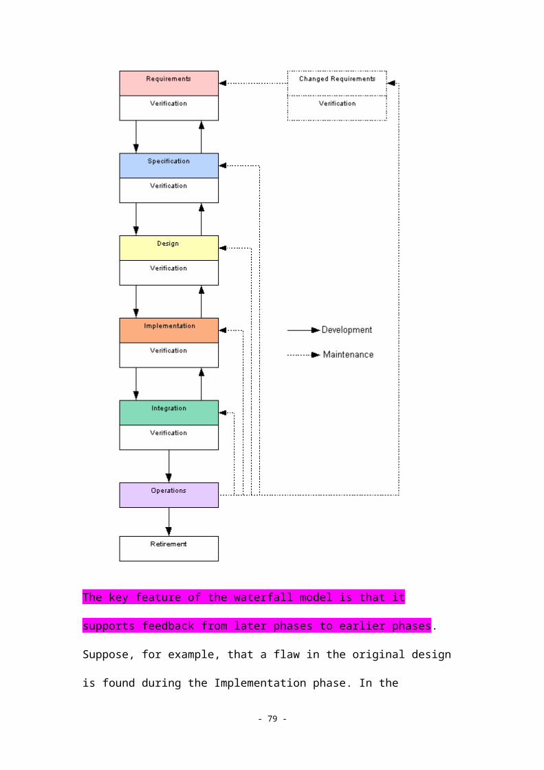
represented as a labeled arrow linking the two use cases, with the arrow pointing toward the use case that is reused.
System boundary: In order to distinguish clearly between the use cases provided by the system and those provided by the actors (users and external agents), a labeled rectangle is drawn around the use cases provided by the software. The system boundary is often omitted when the use cases in the diagram are all associated with a particular software system. However, it is sometimes necessary to model how the same actors interact with different systems, or how systems themselves relate to one another, as in the example of a client-server architecture. In such cases, it is necessary to include the system boundary.
It is important to note that a single use case (or primary functionality) might be associated with many different use case scenarios. While a use case represents a single type of use (for example, saving a file to the local hard drive), the use case scenarios enumerate all types of interactions that might take place when the associated use case is carried out. In this example, the scenarios should describe trying to save a file when the hard drive is full, canceling a request to save a file to disk, and so on. We present more detail regarding use case scenarios and how to write them for each use case in 4.2.3 Writing Use Case Scenarios.
References
Pooley, Rob, and Perdita Stevens. Using UML: Software Engineering with Objects and Components, revised edition. Reading, MA: Addison-Wesley, 1999.
4.2.3 Writing Use Case Scenarios
After identifying all the different user roles and drawing a use case diagram for the software, the analyst writes a series of use case scenarios for each use case. Scenarios that describe the normal flow of events for a particular use case are called "normal" use case scenarios. It is also important to describe what happens when unexpected events occur (for example, disk-full errors, network connection errors, bad input data, etc.). Scenarios that describe the system's behavior in the face of unexpected conditions are called "abnormal" usage scenarios. It is important for the analyst to consider all possible normal and abnormal use case scenarios for a given use case.
Written scenarios are very important, for the following reasons:
- 79 -

Written scenarios help verify coverage and completeness of requirements. It is often the case that the process of gathering requirements with the customer focuses more on normal (expected) sequence of software behaviors, and does not consider all types of unexpected conditions that might occur. Before the design phase can begin, it is essential not only to identify all possible error conditions, but also to define precisely the desired system behavior when errors occur. It is quite common for the analyst to revisit the original requirements specification with the customer in order to discuss error conditions that were not anticipated in the original requirements analysis.
Use case modeling depends on detailed scenarios. The technique used to identify candidate objects in the object-oriented analysis phase, called noun extraction, depends on a detailed description of the desired system behavior. It is not possible to construct a preliminary object diagram using this technique unless detailed scenarios have been constructed.
Schach (4th Edition), figs. 11.2 and 11.3 or Schach (5th Edition), figs. 12.2 and 12.3 or Schach (6th Edition), figs. 12.3 and 12.4 illustrate examples of both normal and abnormal use case scenarios. Although the scenarios are written in plain English, they are not particularly verbose; the focus is on short, concise sentences that detail the stepwise operation of a system in a particular context while carrying out a particular function. It is important to keep the language of the scenarios simple and unambiguous, wherever possible. Simplicity, especially when referring to various elements and actions, helps to avoid a proliferation of redundant objects that really only refer to a single object class. The analyst should review the use case scenarios after they are written to ensure that all of the steps are unambiguous. If any step is described in a way that could be interpreted as more than one concrete action on the part of the software, then the step is ambiguous and must be rewritten.
Take Assessment: Exercise 3
4.3 OOA Practice 2: Class and Dynamic Modeling
4.3.1 Noun Extraction and Preliminary Class List Refinement 4.3.2 Object Diagrams in UML 4.3.3 State Transition Diagrams in UML
Assessments Exercise 4
- 80 -

4.3.1 Noun Extraction and Preliminary Class List Refinement
Readings:
Schach (4th Edition), sections 11.5.1. Schach (5th Edition), sections 12.4.1.
Schach (6th Edition), sections 12.5.1. Schach's Multi-Step Process for Noun Extraction Noun Extraction from Use Case Scenarios
Noun extraction is the first step in class modeling, which is the object-oriented analysis phase that follows use case modeling. Noun extraction is a form of linguistic analysis that is used to analyze use case scenarios and other written descriptions of a system's proposed behavior, in order to define a set of candidate objects or classes. The input to the noun extraction step is either an informal description of the product (as in the multi-step process described by Schach), or the detailed use case scenarios that are created during the use case modeling phase. In this section, we will describe both approaches.
The preliminary class list, which is created by either of the noun extraction techniques, undergoes further refinement as various items that should not be modeled as objects are eliminated. The refinement process is discussed in the context of both noun extraction techniques presented below.
Schach's Multi-Step Process for Noun Extraction
The noun extraction technique described in the Schach textbook is a multi-step process that extracts candidate classes to be included in the class diagram. The steps are listed below:
Concise problem definition: Define the product briefly, in a single sentence if possible.
Informal strategy: Express the informal strategy for solving the problem in a single paragraph, including mention of any constraints on the solution.
Formalizing the strategy: Identify the nouns in the informal strategy, excluding those that lie outside the boundary of the problem. Use these nouns as the candidate classes.
- 81 -

Schach (4th Edition), section 11.5.1 or Schach (5th Edition), section 12.4.1 or Schach (6th Edition), section 12.5.1 gives an example of noun extraction using the case of the elevator controller. The informal strategy is shown here, with the candidate classes (nouns) underlined:
Buttons in elevators and on the floors control the movement of n elevators in a building with m floors. Buttons illuminate when pressed to request an elevator to stop at a specific floor; the illumination is canceled when the request has been satisfied. When an elevator has no requests, it remains at its current floor with its doors closed.
There are eight nouns: button, elevator, floor, movement, building, illumination, request, and door. Three of the nouns (floor, building, and door) do not need to be explicitly modeled by the solution—they are outside the scope of the problem boundary. Three of the remaining nouns (movement, illumination, and request) are abstract nouns that do not correspond to a physical object. Abstract nouns generally do not end up as classes, but they are sometimes modeled as attributes (for example, illumination might be modeled as an attribute of a Button class).
We are left with two candidate classes, Elevator and Button. Since there are two kinds of buttons (in the elevator and on the floors), two subclasses of Button are defined: ElevatorButton and FloorButton.
Noun Extraction from Use Case Scenarios
The multi-step noun extraction process described above works fairly well for simple software systems that do not have many use cases. For more complicated systems, the informal strategy for solving the problem may include several paragraphs. For more complicated software, it may be more appropriate to create a use case diagram and detailed use case scenarios, and to perform noun extraction using the use case scenarios themselves as input.
We illustrate this approach with an example from the analysis of a system called the Knowledge Maintenance Tool (KMT), developed at Carnegie Mellon University. The KMT is a graphical user interface that allows knowledge engineers to edit and update the various knowledge sources used in machine translation systems (dictionaries, grammars, etc.). The following excerpt from the KMT
- 82 -

software documentation describes the normal use case scenario for a grammar update:
The Analyzer maintainer receives a problem report about a sentence that does not pass when it should. He invokes the KMT, and enters the sentence as a test case. The sentence is parsed and the maintainer verifies that the current result is not the desired one. The maintainer then selects module tracing options within KMT, which turns on tracing of the input/output of the Syntaxifier module in the Analyzer. The sentence is run again, and this time the trace output indicates that there is no complete parse. By inspecting the trace output (which indicates the grammar rules that are tried), the maintainer determines that a particular rule which should have fired did not fire, due to a mistake in the rule syntax. The maintainer invokes the Edit capability of KMT on the particular rule. After correcting the rule, the maintainer requests (via KMT) that the Analyzer reload the grammar. The sentence is parsed once again, and the desired result is achieved. The maintainer then refers to the available set of test data for the grammar (Syntaxifier), and runs a set of appropriate regression tests to make sure that the current fix has not caused other bugs in the grammar. Using the KMT interface to run pre-defined test suites, the desired tests are selected and run. Any sentences that fail testing are placed into a new (temporary) set of test cases, and the maintainer iterates through each case using the same set of steps followed for the first bug. When all the work is finished, the maintainer requests that the current (temporary) copy of the grammar be checked back into the file system as a revised version of the original grammar. This new version can be used for further debugging and revision in a later session. Eventually, it will become part of a new frozen version of the entire system for testing and delivery.
This example illustrates why the process of candidate class refinement is important in noun extraction. Many of the nouns that appear in the use case scenario are not candidate class objects, and must be eliminated for the following reasons:
Noun expresses an abstract concept. Some nouns refer to abstract concepts that are not directly a part of the software being constructed (for example, input/output, rule syntax, edit capability, test data, entire system).
Noun expresses a concept outside of the problem scope. Some nouns refer to concepts that are outside of the scope of the problem to be solved; typical examples are those references to the use environment that do not affect the software itself (for example, problem report, rule syntax, current fix, testing and delivery, Analyzer maintainer).
Noun expresses a concept that should be a feature. Some nouns refer to characteristics of data objects that are better modeled as features (class variables) rather than as first-class objects (for example, module tracing options, trace output, result, and version).
- 83 -

After eliminating candidate nouns using these three principles, we are left with the following candidate classes for this use case scenario: Analyzer, module, grammar, rule, sentence, test suite. These objects should be modeled in the class diagram for the KMT tool. It should be noted that some classes would undergo further refinement when the complete class list is created by merging the individual class lists that are produced for individual scenarios. In the KMT example, the classes Analyzer and grammar were eventually refined to server and knowledge base, as they represent occurrences of a more general type of object manipulated by the software.
4.3.2 Object Diagrams in UML
Elevator Example KMT Example
Once a candidate class list has been created through the process of noun extraction, the next step is to draw an object diagram that shows the relationships between the objects (object diagrams are also referred to as class diagrams in some texts). A preliminary object diagram shows only the classes and their relationships; as the object diagram is refined, more detail is added regarding the class variables and methods for each object. The final details (which include the class variable types, as well as the arguments, argument types, and return types for each method) are often not finalized until the Design Phase.
The Unified Modeling Language (UML) contains a convenient notation for drawing object diagrams with the following elements:
Classes: Classes (objects) are represented as labeled rectangles, with three partitions (listed top to bottom): one to hold the label, one to hold the class variable (attribute) declarations, and one to hold the method (action) declarations.
Inheritance links: An inheritance relation between a subclass and its parent class is indicated by a line with an arrowhead, drawn from the subclass to the parent class (the arrow points toward the parent class).
Class relations: A relation between two classes is represented as a line drawn between the two rectangles denoting the two classes. Each relation is marked with a label indicating the nature of the relationship. A relation is also marked with information about the cardinality of the relation. For example, if two classes A and B are related by a one-to-many relation, then a 1 is drawn near the end of the link nearest to class A, and an N is drawn near the end of the link nearest to class B. Similar notation is used for one-to-one
- 84 -

and many-to-many relationships. If the exact cardinality of the relationship is known in advance (for example, one-to-three) then positive integers can be used in place of M or N. In simplified object diagrams, sometimes the relation labels are omitted. A link without cardinality information is assumed to be a one-to-one relation; a link without a label is assumed to denote a generic association (for example, a "part-of" relation).
Elevator Example
Schach (4th Edition), fig. 11.4 or Schach (5th Edition), fig. 12.4 or Schach (6th Edition), fig. 12.5 shows an object diagram for the preliminary class list that was extracted using the three-step technique that we discussed in 4.3.1 Noun Extraction and Preliminary Class List Refinement. The class diagram is drawn using UML class diagram notation. Note that two of the class variables have already been defined, but the rest of the information regarding variables and methods is as yet undefined. The inheritance relationship is represented by the arrow drawn to Button from its subclasses. The relationships between the Elevator and the two types of buttons are drawn as named associations: each association (link) includes a label (communicates with) and cardinality information. The diagram represents the fact that m elevator buttons communicate with n elevators, a many-to-many relationship (from the use case scenario, we know there are m floors; we assume there are n elevators since the number of elevators is unspecified). Since there are m floors, there will be 2m - 2 floor buttons; every floor will have both an Up and Down button, except for the first and top floors, which will have one button each (Up and Down, respectively).
As pointed out by Schach, it is often necessary to refine the initial class diagram to add classes and relationships that more accurately model the real situation (Schach (4th Edition), page 385 or Schach (5th Edition), page 373 or Schach (6th Edition), page 353). In the elevator example, we know that a real elevator does not directly accept commands from the different buttons; rather, an elevator controller handles all the button actions and issues control commands to the elevators. A revised class diagram, including an ElevatorController class, is shown in Schach (4th Edition), fig. 11.5 or Schach (5th Edition), fig. 12.5 or Schach (6th Edition), fig. 12.6.
KMT Example
In 4.3.1 Noun Extraction and Preliminary Class List Refinement, we illustrated the process of noun extraction from a use case scenario
- 85 -

for the Knowledge Maintenance Tool (KMT). The preliminary object diagram is shown in Figure 1 below.
Figure 1: Preliminary Object Diagram for KMT
All the relations are generic taxonomic relations, labeled Contains, which indicates that a given object is associated with one or more other objects. For example, a server (a program that performs some language-processing step) contains many modules, each module is associated with many knowledge files, and each knowledge file contains many rules. This example shows how some of the candidate classes from noun extraction are actually best modeled as attributes, not objects (for example, traceOptions, version, result, traceOutput). The example also shows that some of the methods associated with some objects are already known at this time. While the focus of noun extraction is on the objects, it is relatively straightforward to identify candidate methods by extracting the verbs (action words) from the use case scenario (for example, reload, checkIn, checkOut, edit, run, parse). Although only the checkIn method was implied by the use case scenario, a practitioner familiar with version control will note that every checkIn must be preceded by a checkOut, so this candidate method was added. Note that the method signatures are not fully specified at this time. Only the method names have been identified (the details regarding method arguments and return types will be specified later, during the Design Phase).
4.3.3 State Transition Diagrams in UML
Elevator Example
- 86 -

The techniques of extracting nouns and creating an object diagram are both elements of data modeling, which is concerned with identifying all of the data objects that need to be designed for a piece of software. The analysis process also involves dynamic modeling, which identifies all of the states, events, and corresponding actions to be taken by the software. This information is represented in the form of a state transition diagram.
Unified Modeling Language (UML) contains a special notation for state transition diagrams. This notation includes the following elements:
States: Individual states are represented as rounded rectangles. Each rectangle has two partitions, one containing the state name (label), and the other containing a set of actions to be taken by the software when the state is entered. The set of actions associated with a state may be empty, in which case only the state name (label) appears inside the rounded rectangle.
Transitions: A transition from one state to another is represented as a line with an arrow, drawn from the prior state to the subsequent state. The transition is labeled with a set of predicates that determines when the transition should take place. All of the predicates must be true for the transition to take place. The predicates are drawn as a set of short phrases in square brackets. If a transition from one state to another occurs as soon as the prior state's actions are complete, then there are no predicates controlling the transition and the transition will be drawn as a directed line with no labeling.
Start state: The initial start state is represented as a solid (black) circle, with an unlabeled transition to the first state in the state diagram.
Elevator Example
An example of a UML state diagram for the Elevator Controller scenario is illustrated in Schach (4th Edition), fig. 11.6 or Schach (5th Edition), fig. 12.6 or Schach (6th Edition), fig. 12.7. The start state initializes the system at the Elevator Control Loop state, which is the main "wait" state of the system. There are no actions associated with the Elevator Control Loop state, so only the state name (label) appears inside the rounded rectangle that denotes the state. There are six transitions from the Elevator Control Loop state; each transition is labeled with a set of predicates that must be true for the transition to take place. For example, if the elevator is stopped and there are requests pending, then the Close Elevator Doors state is entered. Note that it is possible for a transition to start and end at the same state.
- 87 -

Take Assessment: Exercise 4
Unit 5. Object-Oriented Design (OOD)
The preliminary class model and dynamic model produced by the object-oriented analysis phase are the input to object-oriented design (OOD). In the OOD phase, the preliminary class model is refined in a detailed class diagram, and the precise dynamic behavior of the system is specified in a set of interaction diagrams. The system's behavior is partitioned into modules (objects and methods) during the architectural design, and the details of individual objects and methods are specified in the detailed design. The final milestone in the design process is the design review, which verifies that the design is internally coherent and reflects the system requirements as captured by the analysis specifications.
In this unit, we present the overall principles of OOD, followed by a detailed discussion of each of the practical techniques used in object-oriented design.
5.1 OOD Principles 5.2 OOD Practice 1 5.3 OOD Practice 2
Assessments Multiple-Choice Quiz 5
5.1 OOD Principles
5.1.1 Cohesion and Coupling 5.1.2 Approaches to Software Design 5.1.3 The Role of Architectural Design 5.1.4 Detailed Design 5.1.5 Design Testing
5.1.1 Cohesion and Coupling
Modularity Cohesion
- 88 -

Coupling
One of the main activities of software design is to partition the functionalities identified in the requirements specification and analysis phases into specific software modules. In traditional structured programming, a software module might correspond to a particular function or program in a particular language. In object-oriented programming, however, a module most often corresponds to an object, or perhaps a method associated with a particular object. Although there are many different ways to partition a particular system into individual modules, software engineers seek a design that maximizes two important characteristics of the system's modules: cohesion and coupling. In this section, we discuss modularity, cohesion, and coupling.
Readings:
Required: Schach (4th Edition), sections 6.1–6.3. Required: Schach (5th Edition), sections 7.1–7.3. Required: Schach (6th Edition), sections 7.1–7.3. Strongly Recommended: Schach (4th Edition), sections 6.4–
6.9. Strongly Recommended: Schach (5th Edition), sections 7.4–
7.9.
Strongly Recommended: Schach (6th Edition), sections 7.4–7.9.
Modularity
In the early history of programming, most programs consisted of a single block of code with numerous sections; program control was transferred from section to section with goto statements, as well as through sequential program execution. Such early systems suffered from being difficult to understand and maintain. In modern approaches to programming (especially object-oriented programming), partitioning a software system into separate modules achieves several important advantages:
Improved understandability: If the executable code statements in a system are grouped together according to function and stored separately, then it is easier to understand what each part of the system does.
- 89 -

Improved testability: Software that is partitioned into modules can be tested both at the modular level and at the system level, making it easier to isolate the cause of system failures.
Improved maintainability: If software is partitioned into modules, then it is much simpler to remove, replace, or rewrite a particular part of the system's functionality, with minimal impact on the other parts of the system.
The general advantages of modularity are illustrated by the simple (but compelling) example presented in Schach (4th Edition), figs. 6.1-6.3 or Schach (5th Edition), figs. 7.1-7.3 or Schach (6th Edition), figs. 7.1-7.3. The examples show how difficult it would be to understand or extend a computer hardware design if its logic was partitioned into three chips consisting of AND, OR, and NOT gates (instead of partitioning the logic into functional modules, such as Registers, ALU, and shifter).
Cohesion
The term cohesion is used to refer to the degree of similarity or interaction among the steps carried out by a particular module. A module with high cohesion provides a set of operations that are logically grouped together. In a module with low cohesion, completely independent functions are grouped together in an arbitrary manner. Also, the operations in a module with high cohesion operate on similar data whereas those in a module with low cohesion operate on different kinds of data elements.
Seven different types of cohesion are defined in Schach (4th Edition), section 6.2 or Schach (5th Edition), section 7.2 or Schach (6th Edition), section 7.2. In this course, we are mainly concerned with the two most important types of cohesion:
Informational cohesion: A module has informational cohesion if it performs a number of actions, each with its own entry point, with independent code for each action, all performed on the same data structure.
Functional cohesion: A module that performs exactly one action or achieves a single goal has functional cohesion.
The concept of informational cohesion should seem very familiar—it captures the essence of objects in an object-oriented framework. Indeed, properly implemented classes in Java have all the characteristics of informational cohesion: the actions are the object
- 90 -

methods; each action (method) has its own entry point (method signature) and independent code (method definition); and the methods typically operate on the same data structure (the class variables inside the object).
Functional cohesion is also a very important type of modularity, for it describes modules that are so tightly cohesive that they can be reused anywhere. Examples of functionally cohesive modules include global subroutines that are called by many different programs (for example, disk I/O system calls).
It is important to note that the evolution of object-oriented technology did not happen overnight with the introduction of a particular object-oriented language; in fact, there has been a slow trend towards programming languages with better built-in support for informational cohesion, which is a property of software design (rather than a particular programming language). For a detailed example of cohesion, see Schach (4th Edition), fig 6.7 or Schach (5th Edition), fig 7.7 or Schach (6th Edition), fig 7.7.
Coupling
The term coupling is used to refer to the degree of interaction between two modules. In the earlier history of programming, it was quite common for modules to modify data or even program statements inside other modules. In modern terms, this would be equivalent to a method in one Java class changing the program code inside another method in a different class—at run time! Whatever advantages this content coupling may have had when memory was at a premium and processors were very slow, it resulted in programs that were difficult (if not impossible) to understand, debug, and modify over time. Other types of coupling (listed from least to most desirable) include the following:
Common coupling: Two modules can both access and modify a global data structure.
Control coupling: The results of one module influence the subsequent actions (control decisions) of another module.
Stamp coupling: A complex data structure is passed from one module to another, but the called module only utilizes some subset of the data passed to it.
Data coupling: All arguments passed to a called module are either simple data types or complex data structures where all the data elements are utilized.
- 91 -

Two modules exhibit a low degree of coupling if they are not coupled at all, or if only data coupling exists between them. Data coupling can be thought of as the simplest way for two modules to share data, in a manner that is easier to understand, debug, and modify over time. All other kinds of coupling are less desirable to some degree. Common-coupled modules are hard to debug because it can be difficult to determine the cause of corruption in the global data structure. Control-coupled modules are difficult to debug or extend because changes in one module can have unforeseen consequences in another module. In addition, stamp-coupled modules are hard to understand because not all the data passed between modules is actually needed. A detailed coupling example is illustrated in Schach (4th Edition), figs. 6.11-6.13 or Schach (5th Edition), figs. 7.11-7.13 or Schach (6th Edition), figs. 7.11-7.13.
For further reading on modularity, cohesion, coupling, and other properties of modules and objects, refer to Schach (4th Edition), Chapter 6 or Schach (5th Edition), Chapter 7 or Schach (6th Edition), Chapter 7.
5.1.2 Approaches to Software Design
Action-Oriented Design Data-Oriented Design Object-Oriented Design
Throughout this course, we have focused on two main aspects of software systems: the actions they perform and the data on which they operate. Therefore, it is not surprising that the two traditional ways to approach software design are referred to as action-oriented design and data-oriented design.
Readings:
Schach (4th Edition), sections 12.1–12.7. Schach (5th Edition), sections 13.1–13.7.
Schach (6th Edition), sections 13.1–13.9.
In action-oriented design, the emphasis is on the actions performed by the software, and design activities are oriented around defining the system's modules from the perspective of actions (for example, using a technique such as data-flow analysis). In data-oriented
- 92 -
design, the primary focus is on the structure of the data to be represented in the system.
With the exception of pure database systems, most software designs have equal emphasis on actions and objects. Therefore, an approach that emphasizes one over the other will run the risk of introducing a design flaw in the aspect of the system that did not receive primary emphasis. Object-oriented design alleviates this risk by considering both actions and data with equal emphasis (much the same way that methods and data receive equal status in an object definition).
Action-Oriented Design
In an action-oriented approach, the focus is on analyzing the processing steps and partitioning them into a sequence of actions (modules) with high cohesion and low coupling. This approach is most appropriate for those cases for which the flow of data through the system is the most important way to view the operation of the software. (Database, rule-based, and transaction processing systems are examples of systems where data flow through is not the most important way to view the operation of the software.) There are two main techniques for action-oriented design:
Data flow analysis: Using structured analysis techniques, the designer creates a data flow diagram showing all the processing steps plus their input and output. The designer then identifies the highest point of abstraction of both the input and the output—the boundaries between internal and external representations of the data—and draws two vertical lines separating the input, processing, and output stages. The processing steps are then partitioned into input, transform, and output modules—according to where these boundaries are drawn. This technique is applied recursively to each of the three initial modules, which are further decomposed. The process continues until the modules identified perform a single function or a group of functions with very high cohesion. A detailed example of data flow analysis can be found in Schach (4th Edition), section 12.3 or Schach (5th Edition), section 13.3 or Schach (6th Edition), section 13.3.
Transaction analysis: In a transaction processing system, a large number of very similar requests must be handled that differ only in the details of their content. For example, an automated teller machine is a typical example of a transaction processing system. Rather than focusing on defining input, processing, and output modules, transaction analysis focuses on identifying the analysis and dispatch modules. The analysis module determines the type of the incoming transaction and passes this information to the dispatch module, which performs the appropriate transaction. An example of a transaction
- 93 -

analysis can be found in Schach (4th Edition), section 12.4 or Schach (5th Edition), section 13.4 or Schach (6th Edition), section 13.4.
Data-Oriented Design
In data-oriented design, the modular architecture of a system is based on the structure of the data that it processes. The best-known technique for data-oriented design is the Jackson Method (Jackson, 1975; 1983). Historically, action-oriented design has been much more widely used than data-oriented design. Given the current trend away from both of these traditional methods towards object-oriented design, data-oriented design has largely fallen out of use. As a result, it is not discussed in detail in this course. Students who are interested in more detail should consult the original Jackson works about data-oriented design.
Object-Oriented Design
In object-oriented design, equal emphasis is given to designing both the data in the system and the actions of the system. Specifically, the design of the system is oriented around the definition of a set of objects that represents the classes that were identified during object-oriented analysis. Since object definition in a language like Java supports high cohesion and low coupling, the object-oriented approach has "built-in" support for the more desirable characteristics in modular design. The object-oriented design approach consists of the following four steps:
Construct interaction diagrams. The designer creates a sequence diagram or a collaboration diagram for each of the use case scenarios defined during the analysis phase.
Construct a detailed class diagram. The preliminary class diagram created during the analysis phase is elaborated to include a full list of methods (including their signatures and return types) and data members (including their types). Additional classes and relationships are added where necessary.
Construct a client-object relation diagram. The designer then arranges the classes in a diagram that emphasizes their hierarchical relationship; this corresponds to the notion of a control flow diagram (CFD) in structured analysis.
Complete a detailed design. The designer then specifies the algorithms to be implemented for each method, along with the internal variables and data structures required by each method.
- 94 -

A more detailed discussion of the phases in object-oriented design will be presented later in this unit.
References
Jackson, M.A. Principles of Program Design. New York: Academic Press, 1975.
Jackson, M.A. System Development. Englewood Cliffs, NJ: Prentice Hall, 1983.
5.1.3 The Role of Architectural Design
Regardless of the technique that is used to design the modules of a software system (action-oriented, data-oriented, or object-oriented), the result is called the architectural design of the system. So far, we have introduced the important characteristics—modularity, cohesion, and coupling—that motivate a good architectural design. However, we have not said much about the role that architectural design plays in the overall creation of the software system. In fact, architectural design is just the first step in design; it is followed by the detailed design phase and the design-testing phase. Architectural design is also important during the implementation and integration phases. The breakdown of a system into specific modules and module relationships is used in the following ways:
During detailed design: During the detailed design phase, each of the modules identified in the architectural design is specified in detail, including a pseudo-code representation of its algorithm(s), and definitions of its signature(s) and data members. This step cannot proceed until an architectural design has been completed.
During design testing: The structures created during architectural design are an important vehicle for design testing, where the use case scenarios are followed in a simulated walk-through of the system's operation. Such testing is impossible without a representation of the individual modules and their interrelationship (coupling).
During implementation and integration: As will be discussed in 6.3 Integration Testing, architectural design is a key element in planning the implementation and integration of the system's modules. All of the methods discussed (top-down, bottom-up, and sandwich integration) rely on a detailed architecture design as input.
As mentioned earlier, a good architectural design also promotes understandability, faster debugging, and straightforward
- 95 -

maintenance and extension—all of which are extremely important cost factors in the overall software life cycle.
5.1.4 Detailed Design
Readings:
Schach (4th Edition), section 12.8. Schach (5th Edition), section 13.8.
Schach (6th Edition), section 13.12.
During the detailed design phase, the designer considers each module identified in the architectural design and produces the following specifications:
Module interfaces: The names, arguments, and argument types of all the modules are specified in detail. In an object-oriented system, this involves specifying, for each object in the detailed class diagram, the signatures for the object constructor and for all the object methods.
Module algorithms: The actual algorithms to be used in implementing each module are specified concretely. Algorithms can be specified using prose descriptions, but since English prose is notoriously ambiguous, it is preferable to specify algorithms in a semi-formal language or pseudocode. In an object-oriented system, this involves specifying for each object in the system the algorithms for the object constructor and for each of the object methods. An example of pseudocode for a single method can be found in Schach (4th Edition), fig. 12.16 or Schach (5th Edition), fig. 13.17 or Schach (6th Edition), fig. 13.12.
Module data structures: If a module requires temporary storage or any kind of internal data structure, these must be specified concretely. This involves defining a name, type, and initial value (if appropriate) for each internal variable or data structure. In an object-oriented system, this involves specifying all the class variables for a particular object, as well as all the internal variables and data structures inside each method, where appropriate.
When the detailed design is complete, all the information required by the programmer should be defined. A common way of writing down the detailed design for object-oriented Java programs is to write skeletal class files for each object—in which class variable declarations and constructor and method signatures would be included. Algorithm specifications are placed in each method body in the form of comments.
- 96 -

The advantages of this approach cannot be over-emphasized. By allowing experienced designers (who themselves are senior programmers) to predefine the structure and content of the objects to be written, junior programmers are free to concentrate on creating excellent code for individual modules, rather than on struggling with the complexities of a global system design, for which they may be unprepared. When an excellent detailed design is constructed in advance, the implementation stage proceeds in a rapid, straightforward manner and fewer faults are discovered during system integration and testing.
More information on detailed design can be found in Schach (4th Edition), section 12.8 or Schach (5th Edition), section 13.8 or Schach (6th Edition), section 13.12.
5.1.5 Design Testing
Readings:
Schach (4th Edition), sections 12.10–12.11. Schach (5th Edition), sections 13.10–13.11.
Schach (6th Edition), sections 13.10–13.11, 13.14.
Design testing has two main goals:
To verify that the design incorporates all the functional specifications from the requirements and analysis phases;
To ensure correctness of design
It must be possible to link each of the processing steps identified in the analysis phase (for example, in the data flow diagrams) to modules specified in the architectural design. In the case of object-oriented design, all of the use cases identified must correspond to some sequence of actions provided by the modules in the system (more specifically, the objects and their methods). Wherever possible, it is useful to cross-reference the elements of the design with those aspects of the requirements and analysis phases that they implement. In the case of object-oriented design, this mapping is usually straightforward. Such a design proceeds from a correlation between the preliminary and detailed class diagrams. Any changes to the class diagram must be documented, and it must be verified that both the detailed class diagram and the detailed design support
- 97 -

the use case scenarios defined during the analysis phase. Some computer-aided software engineering (CASE) tools support a direct mapping between specifications and design (for example, see Rational Rose at http://www.rational.com/products/rose/).
It is also important to consider each aspect of the design and review it rigorously to uncover any design faults before implementation begins. In 5.3.4 Formal Design Review, we discuss the formal design review, a process that examines all the elements of the design in detail.
5.2 OOD Practice 1
5.2.1 Sequence Diagrams in UML 5.2.2 Collaboration Diagrams in UML 5.2.3 Detailed Class Diagrams in UML
Assessments Exercise 5
5.2.1 Sequence Diagrams in UML
The first step in object-oriented design is the creation of an interaction diagram for each use case scenario. Unified Modeling Language (UML) supports two types of interaction diagrams: sequence diagrams and collaboration diagrams. Both kinds of diagrams depict the system's objects and the messages passed between them. Sequence diagrams emphasize the chronological sequence of messages and are important for understanding the order in which certain events occur in a software system. Collaboration diagrams (treated in 5.2.2 Collaboration Diagrams in UML) emphasize the relationships between objects and are important for understanding the structure of the software system.
The graphical notation used in UML to specify sequence diagrams includes the following elements:
External agents (such as the user) and all of the objects in the system are represented as labeled, parallel vertical lines;
Messages from an agent to an object, or from object to object, are represented as labeled arrows, drawn from the agent or calling object to the called object. Labels include increasing ordinal numbers, which represent the chronological sequencing of messages.
- 98 -

Messages are generally arranged in the vertical dimension, with the earliest message appearing at the top and later messages appearing below. In this manner, it is possible to "read" the sequence diagram from top to bottom to discern the chronological ordering of messages.
A simple, abbreviated example of a sequence diagram for a client-server architecture is shown below:
A detailed example of a sequence diagram is shown in Schach (4th Edition), fig. 12.12 or Schach (5th Edition), fig. 13.12, which depicts the sequence diagram for one use case scenario associated with the ElevatorController case study.
5.2.2 Collaboration Diagrams in UML
In contrast to sequence diagrams, which present the chronological sequencing of messages, collaboration diagrams emphasize the relationships between objects. The UML notation for a collaboration diagram includes the following elements:
Agents (such as the user) are represented as labeled stick figures (identical to their representation in use case diagrams);
Objects are represented as labeled rectangles;
- 99 -

Coupling between two objects (which implies that one object passes one or more messages to another) is represented as a solid, undirected line linking the rectangles that denote the objects;
Individual messages are represented as labeled, directed lines with their arrow pointing in the direction of the object that is called or invoked. The messages labels include ordinal numbers that denote the chronological ordering of the messages.
Shown below is a partial collaboration diagram for the simple client-server architecture introduced in 5.2.1:
A detailed example of a collaboration diagram is illustrated in Schach (4th Edition), fig. 12.13 or Schach (5th Edition), fig. 13.13. It should be clear from the example (which represents the same scenario as the sequence diagram in Schach (4th Edition), fig. 12.12 or Schach (5th Edition), fig. 13.12 that collaboration diagrams are equivalent to sequence diagrams—but visualize the information about message passing differently. The design team must decide whether to use sequence diagrams, collaboration diagrams, or both types of diagrams as interaction diagrams in the design phase. The decision depends on whether the chronological ordering of messages is more important than the overall structure of the object interactions, or vice versa.
5.2.3 Detailed Class Diagrams in UML
- 100 -

After the interaction diagrams are constructed in the object-oriented design phase, it is possible to create a detailed class diagram that refines (and finalizes) the proposed classes for the system. Recall that the object-oriented analysis phase produces a preliminary class diagram that indicates the classes, attributes, and relations, but does not give any detail regarding the class methods.
The basic task in building the detailed class diagram is to associate the messages specified in the interaction diagrams with particular classes. An action or a message can be associated with either a class or a client that sends a message to an object of that class. There are at least three techniques for deciding how to associate messages with classes:
Information hiding: Because the state variables of a class should be declared private or protected, actions on state variables must be local to the class where they are declared.
Reduced redundancy: Even when information hiding is not required, if an action is invoked by a number of different clients of a particular object, then it makes sense to have a single copy of that action implemented as a method of the object. The alternative (a separate copy of an identical method in each client class) is redundant, adds to the complexity of the code, and decreases the modularity and extensibility of the code.
Responsibility-driven design: According to the principle of informational cohesion, modules that group together all actions on a set of data elements have high cohesion, and a design that promotes informational cohesion is preferred. Given this rationale, it often makes sense for the action associated with a message to be implemented as a method of the object that receives the message, since it is often the responsibility of that object to operate on the data involved in the activity.
A detailed example applying these criteria to a particular class diagram can be found in Schach (4th Edition), section 12.7 or Schach (5th Edition), section 13.7 or Schach (6th Edition), section 13.7.
Take Assessment: Exercise 5
5.3 OOD Practice 2
5.3.1 Client-Object Diagrams in UML 5.3.2 Specifying Modular Interfaces 5.3.3 Detailed Design Specification 5.3.4 Formal Design Review
- 101 -

Assessments Exercise 6
5.3.1 Client-Object Diagrams in UML
Once the detailed class diagram has been created, the final step in architectural design in the object-oriented approach is to create a client-object diagram. The client-object diagram specifies the product in terms of clients of objects. Specifically, an object C that sends a message to object O is a client of O. UML notation is used to draw all the classes and their associated client-object relations. This simple diagram contains just two elements:
Classes: Classes are represented as labeled rectangles, identical to the representation used in sequence diagrams and collaboration diagrams;
Relations: Client-object relations are represented as unlabeled, directed lines drawn from the client C to the object O (arrows point from clients to objects).
Once the client-object diagram has been created, it is possible to identify the objects that are not invoked by any clients. These top-level objects represent the possible entry points into the entire product. If there is only a single top-level object, then a main method is defined, and the object is instantiated when the program is first called. If there is more than one top-level object, it may be necessary to create a single top-level object that has a client-object relation with the multiple existing top-level objects (for example, the Java interpreter can only be called with a single top-level class as the entry point).
An example of a client-object diagram is shown below:
- 102 -

This client-object diagram illustrates an architecture where there are two top-level modules (clients) that are not clients of any other objects. In a Java implementation, an additional class must be added to instantiate both of these top-level objects. This is commonly done in a top-level "session" or "user interface" object.
A more detailed client-object diagram for the ElevatorController case study is illustrated in Schach (4th Edition), fig. 12.15 or Schach (5th Edition), fig. 13.16.
5.3.2 Specifying Modular Interfaces
The detailed class diagram specifies enough information about the product's modular structure (including method signatures) that it is possible for a programmer to begin implementation of classes based on the detailed class diagram. However, in practice, it is often preferable to specify the modular interfaces in a separate step before beginning the full implementation of each class.
In Java, the modules are simply the classes to be defined, and the modular interfaces contain the following information:
Class variable definitions: The names and types of any class variables contained by the class
Constructor signatures: The names and types of any arguments of the object constructor for the class
Method signatures: The name and return type of each method, plus the names and types of its arguments, if any
- 103 -

To specify the modular interfaces before full implementation begins, a recommended coding convention is to create a skeletal class file for each class. The skeletal class file contains only the information specified above and does not actually implement the program statements in the body of the constructor or other class methods. Writing skeletal class files for the classes in the detailed class diagram is also an excellent way to validate the class diagram. When writing the Java method signatures into the class files, it often becomes apparent when some element of the design is missing or incorrect.
5.3.3 Detailed Design Specification
In 5.1.4 Detailed Design, we introduced the detailed design phase and described it in general terms as the specification of the interface, algorithm, and data structures for each module. In object-oriented design, the interface and data structures are specified in the detailed class diagram and the skeletal class files (modular interface). The remaining element of the detailed design, the algorithm description, must be included in a prose description or pseudo-code definition for each of the methods in the modular interface.
For complex methods, including a text description or full pseudo-code in the skeletal class file may make the file difficult for a programmer to read. On the other hand, we have been stressing the idea that the detailed design should present all the important design information to the programmer in a conveniently organized manner—a principle that favors placing the algorithm specifications directly into the skeletal class files. An appropriate compromise (which should be sought when the methods are sufficiently complex) is to place a pointer to the algorithm specification inside the skeletal class file and to store the algorithm description itself in a separate file.
The Java Development Kit (JDK) distributed by Sun Microsystems includes an automatic documentation generation facility called javadoc (http://java.sun.com/j2se/javadoc/index.html). The javadoc tool extracts comments written in the "doc" format from Java source files. It places them in a user-specified destination directory, creating a set of HTML pages that, depending on the options given by the user, describes public and protected classes, interfaces, constructors, methods, and fields. javadoc is targeted for use with APIs, but it can be used for other purposes as well. Doc
- 104 -

comments begin with a short description of what the item to which the comment pertains does. More text formatted with a restricted number of HTML tags can be added. Then there are a number of different tags, identified by an at sign ( @ ) as their first character, for different types of items (for example, class and interface tags, field tags, constructor and method tags).
The following are examples of doc comments.
An example of a class doc comment:
/** * A class representing a window on the screen. * For example: * * Window win = new Window(parent); * win.show(); * * * @author Sami Shaio * @version %I%, %G% * @see java.awt.BaseWindow * @see java.awt.Button */class Window extends BaseWindow {... }
An example of a field doc comment:
/** * The X-coordinate of the window. * * @see window#1 */int x = 1263732;
An example of a method doc comment:
/** * Returns the character at the specified * index. An index ranges from 0 to length() - 1. * * @param index the index of the desired
- 105 -

* character. * @return the desired character. * @exception StringIndexOutOfRangeException * if the index is not in the range * 0 to length()-1. * @see java.lang.Character#charValue() */public char charAt(int index) { ... }
If the designer takes care to format the skeletal class files and method descriptions using the javadoc syntax and tagging conventions, then javadoc can be used to generate automatically, full class documentation in HTML format. While it can be time-consuming to format comments using the javadoc syntax, the cross-referenced HTML produced by the tool is a very powerful source of documentation that would require much more effort to produce from scratch. The compelling characteristic of javadoc is that it allows the designer or programmer to produce HTML documentation "for free" from the detailed design specification (in the form of skeletal class files), even before the methods are implemented.
5.3.4 Formal Design Review
The final milestone and validation step in the design process is the formal design review. The entire product design (including the sequence diagrams, collaboration diagrams, detailed class diagram, client-object diagram, modular interface specification, and detailed design specification) are reviewed, both for their consistency with each other and for their conformity to the original functional requirements specified in the analysis phase.
During a formal design review, the designer might meet with the programmers selected to implement the product, as well as with the engineer who performed the original requirements analysis and specification (if they are different individuals). A typical formal review is scheduled at a time such that all of the relevant specification documents and diagrams can be distributed to all participants well in advance. The focus in the design review meeting should not be on "bringing everyone up to speed" on the design, although a certain amount of clarification is inevitable. The design review should focus on the following activities:
- 106 -
Match the design to the requirements. All of the use cases and use case scenarios identified during object-oriented analysis should be reviewed to verify that the final design includes appropriate classes and messages (method calls) that model all the events sketched in the scenarios. Manually tracing through the sequence diagrams and/or collaboration diagrams is an appropriate technique for this activity.
Verify completeness of the detailed class diagram and detailed design. Sometimes simpler methods (such as get and set accessors for class variables) are overlooked. During the design review, it is important to verify the completeness of the class diagram and detailed design, so no methods (however small or trivial) are overlooked. Are the actions in the sequence/collaboration diagrams associated with the right classes—according to the principles of information hiding, reduced redundancy, and responsibility-driven design? Are the algorithm descriptions in the detailed design complete, precise, and unambiguous? The programmers should attend the design review and verify that the detailed design contains all of the information required for implementation to begin.
Evaluate the architectural design. Do the proposed modules exhibit the right degree of cohesion and coupling? Are there any instances of coupling that should be re-designed to avoid unnecessary common coupling, control coupling, or stamp coupling?
Since the formal design review represents the official "hand-off" of the design specification to the implementation team, it is critical that enough time be taken to conduct a detailed, exhaustive review of the design. The design review is typically the best (and sometimes the last!) opportunity for the implementation team to work with the design team to refine the design before implementation begins.
Take Assessment: Exercise 6
Exam 2
To complete this exam, you must complete both the multiple choice and practical sections. You may do them in any order. Each is timed separately, so they may be completed at different times.
Exam 2 Multiple-Choice Exam 2 Practical
Unit 6. Build and Test the Solution
In this unit, we examine some aspects of building and testing systems. There is not a lot that can be said about implementation
- 107 -

beyond providing general guidelines. Each project has its own specific needs and many decisions will be based on those needs. We will briefly discuss 1) some implementation strategies such as rapid prototyping and reuse, 2) the issue of choosing an implementation language, and 3) good programming practices. Then we will switch to different approaches and techniques for testing individual modules, module integration, and the final product.
The relative timing of implementation, testing, and integration depend on the choice of life-cycle model that is adopted. For example, if one follows a strict waterfall model, implementation and module testing take place at the same time, while integration testing follows strictly after the implementation phase. In both the incremental and synchronize-and-stabilize models, module, integration, and product testing will be repeated several times—once for each release of the product. In an object-oriented life-cycle model, the implementation and integration phases are more closely coupled than in non-object-oriented models. Furthermore, it is not only the choice of life-cycle model but also management and planning considerations that will also determine the development order of modules, and, therefore, their individual testing and the possible order of their integration.
6.1 Implementation 6.2 Module Testing 6.3 Integration Testing 6.4 Product and Acceptance Testing 6.5 CASE Technology
Assessments Exercise 7 Multiple-Choice Quiz 6
6.1 Implementation
6.1.1 Reuse 6.1.2 Choice of Programming Language 6.1.3 Good Programming Practices and Coding Standards
6.1.1 Reuse
Module Reuse
- 108 -

Costs and Constraints in Reuse What Can Be Reused and When? Reuse and Maintenance
Module Reuse
The first issue one faces in implementation is whether to code everything from scratch or whether to reuse existing components. Although components from all phases of the software process can be reused (requirements, specifications, design, documentation, and even testing suites), module reuse is by far the most common type of reuse.
Readings:
Schach (4th Edition), sections 7.1–7.6. Schach (5th Edition), sections 8.1–8.6.
Schach (6th Edition), sections 8.1–8.6.
Reuse refers to taking the components of one product to facilitate the development of a different product with a different functionality. Reuse can be accidental, if developers realize that a previously developed component can be reused—or reuse can be deliberate. In the latter case, components are constructed with the idea of possible future reutilization in mind. Deliberate reuse is better, insofar as such components are likely to be better documented, better tested, and designed in a uniform style that makes for easier maintenance. However, even reused components will have to be retested during integration testing, because the range of input they get in a new product might go beyond that of the previous product or products.
In the early days of system building, there was no reuse: everything was constructed from scratch. The first common source of code reuse was subroutine or class libraries, of which there are now many in the public domain for different languages. For example, many scientific computing subroutines have been developed and refined for optimal performance, so in the case of each of these subroutines there is no need to recode one. Application Programming Interfaces (APIs) are usually implemented as operating system calls, but they can be viewed as subroutine libraries. Code reuse is also a feature of the many varieties of toolkits for building graphical user interfaces (GUIs).
- 109 -

Costs and Constraints in Reuse
In reality, only a relatively small percentage of any software product serves a novel purpose or provides novel functionality—approximately 15 percent. That means that, in theory, about 85 percent could be standardized and reused. In practice, on average, only 40 percent is reused. Smaller modules are frequently more reusable because they are likely to be documented better and less application specific.
There are several good and some not so good reasons that tend to limit the extent to which code is reused. One common reason is ego: the fact that many software professionals would prefer to rewrite a piece of code from scratch rather than use someone else�s. A related reason has to do with quality. Developers would reuse code developed by others if they could be assured that it would not introduce faults in the new product. While this concern is sometimes justified, both reasons reflect the attitude that no piece of code is as good as one�s own! There are also practical problems associated with reuse. Retrieval is one: unless code is deliberately developed and organized for easy reuse, it may be difficult to locate it in a database of hundreds and thousands of software modules. Moreover, planning for reuse has a price: an increase of 60 percent or higher in development cost—plus the cost of reusing the component and the cost of implementing a reuse process. Finally, there may be legal issues to consider. In contract software development, the software belongs to the client, unless it is just licensed. Internal software reuse, however, is free from this constraint.
Object-oriented systems seem to be particularly suited to code reuse. Objects are self-contained, which can make both development and maintenance easier because it allows a large product to be constructed as a collection of smaller products. Maintenance is generally easier and cheaper, and some classes of objects can be reused. However, reuse in object-oriented systems presents its own problems, some of which are specifically due to inheritance. One kind of problem, known as the fragile base class problem, occurs when a base class changes. All classes depending on a base class that has changed have to be recompiled at least, and possibly changed. Another kind of problem is due to indiscriminate use of inheritance: because dependent classes not only inherit all the attributes of their superclasses but also have their own attributes, they can get big very quickly! A third kind of
- 110 -

problem concerns the use of polymorphism and dynamic binding. Polymorphism and dynamic binding represent the ability to invoke the same method with arguments of different kinds and have the run-time system determine the appropriate method to use based on the type of argument. As powerful as it is, this mechanism makes maintenance and reuse of code more difficult to understand and troubleshoot. These problems are discussed in more detail in Unit 8.
What Can Be Reused and When?
Reuse is commonly perceived as being something you do with individual code modules, as in the case of subroutine libraries, but code is not the only thing that can be worth reusing. For example, if one can browse the inheritance tree of an object-oriented system, its design can become reusable as well.
There are two approaches to incorporating reuse into the code design and implementation phases:
1. One can develop the control logic for a product from scratch and reuse pieces of code that incorporate specific operations of the product.
2. Alternatively, one can reuse an application framework that already provides the desired control logic and develop application specific operations.
An example of an application framework that can be reused is the set of classes used for the design of a compiler. One will need to code from scratch all classes specific to the language and desired target machine. Application framework reuse results in higher productivity than toolkit or library reuse because more design is reused (recall that design typically has a higher financial cost than implementation); because logic is harder to design and code than are the specific operations; and because the control logic will have been tested. Code frameworks, those for performing basic window manager operations, for example, are similar to application frameworks in reusability.
Design patterns are another kind of design reuse. A design pattern is a solution to a general design problem in the form of a set of closely interacting classes that have to be customized to create a specific design. The idea of design pattern is drawn from the field of building architecture. A GUI generator, which is a tool that assists the user in constructing a graphical user interface, is an example of a design pattern. It provides a set of abstract widget classes that
- 111 -

the developer can combine to create a custom user interface. A widget is a graphical object such as a window, a menu, a radio button, etc. The abstract widget classes have concrete subclasses whose instantiations are widgets with a specific "look-and-feel"—such as Motif, SunView, and others. A detailed description of a GUI generator is given on Schach (4th Edition), section 7.5.3 or Schach (5th Edition), section 8.5.3 or Schach (6th Edition), section 8.5.3.
Software architecture is another design concept that, in the future, may lend itself to reuse. The term "software architecture" refers to design issues concerning the organization of a product in terms of its components, product-level control structures, issues of communication and synchronization, databases and data access, physical distribution of the components, performance, and choice of design alternatives. Object-oriented architectures, UNIX pipes and filters, and client-server architectures are all examples of software architectures.
Reuse and Maintenance
Software reuse makes economic sense, particularly in an organization that produces software for a specific application domain. The higher up-front costs of designing and implementing for reuse are more likely to pay off during development of future products, resulting in both significant savings of cost and time. However, in order for reuse to bear fruit, there must be a commitment from management: programmer initiative is not enough. You should read about reuse case studies in Schach (4th Edition), section 7.3 or Schach (5th Edition), section 8.3 or Schach (6th Edition), section 8.3
Although the traditional reason for reuse has been to shorten development, the potential beneficial effects of reuse also extend to maintenance. In fact, reuse has more impact on maintenance than on development because the cost of maintenance over a product‘s lifetime is roughly twice that of development (from requirements analysis through integration testing and delivery). It is worth repeating that the crucial advantage of reuse is the availability of well-documented and well-tested code. Reusing code that does not have these characteristics has little benefit and potentially can cause significant harm.
6.1.2 Choice of Programming Language
- 112 -

Programming Language Types Rapid-Prototyping Language Final Product Language
While design and code reuse may be an option for some portion of a new software product, a larger part of the product will need to be implemented from scratch. One of the major decisions to be made will be the programming language to use for developing the product. We begin with a brief survey of programming languages, and then continue on to guidelines for choosing a programming language.
Readings:
Schach (4th Edition), sections 13.1–13.2. Schach (5th Edition), sections 14.1–14.2.
Schach (6th Edition), sections 14.1–14.2.
Programming Language Types
Software practitioners often talk about fourth-generation languages. There is a history here. First-generation languages were binary machine code, sequences of zeros and ones, encoding information at the level at which machines process it directly. First-generation languages were quite tedious to write in and very hard to debug. Things improved a bit when assembly languages, second-generation languages, were developed in the late 1940s and early 1950s. Although more understandable, assembly languages were still very processor dependent. The instructions reflected the architecture of the processor (for example, how many registers there were). Individual instructions had to be very specific (for example, copy the contents of register 1 to register 3) and complex control structures such as loops had to be spelled out in excruciating detail.
At least from the programmer's perspective, the need for processor independence and significantly more abstract control structures was the territory conquered by third-generation languages. These include familiar high-level languages developed in the 60s and 70s, such as FORTRAN, Algol, Pascal, COBOL, C, and Lisp. Third-generation languages are still procedural languages, but each instruction in a high-level language corresponds to five to ten machine code instructions. Object-oriented languages can also be
- 113 -

considered third-generation languages, though they organize data and computation in a very different way. The first object-oriented language was Smalltalk, followed soon thereafter by C++ and more recently Java. Object-oriented programming has become more and more popular. Even artificial intelligence languages such as Lisp, designed for symbolic computation, now have support for object-oriented programming.
Fourth-generation languages (4GLs) were intended to abstract out even more procedural detail by encoding in a single statement even more lines of machine code (30–50 lines). Several of them are non-procedural—that is, they specify what should happen but not how it will happen. There is no single 4GL; rather, several special purpose 4GLs have been developed. A well-known 4GL is SQL, a language for accessing information in relational databases (for example, Oracle databases). A probably less known example of a 4GL is Prolog, commonly used in artificial intelligence applications and especially in natural language processing. A Prolog statement can be used to specify, for example, that a sentence is composed by a noun, followed by a verb, followed by another noun. This statement can be used to analyze a text sentence and determine whether it fits the noun-verb-noun pattern. Exactly how that happens is hidden from the user in the search mechanism that is deep inside the Prolog interpreter.
Because of the high ratio of number of 4GL code lines to machine code lines, one would think that use of a 4GL would increase programmer productivity significantly. In fact, the results have been inconsistent, with reports ranging from a tenfold increase in productivity, to a negligible increase, to a significant decrease. It is difficult to evaluate these reports and make a general statement because much depends on the particular 4GL and its suitability for the application. Other factors that influence the impact of introducing a 4GL into an organization include the availability of CASE tools and the maturity of the organization. There are also serious risks in using 4GLs. Many were intended for end-user programming—that is, for allowing end-users to bypass the programmers in the organization and to write the code required by their specific information access needs on their own. The danger is that end users who are not experienced programmers may place too much trust in the correctness of the output from their 4GL programs and make harmful decisions based on erroneous output. Equally serious is the possibility of an incorrect program modifying a database and corrupting shared data.
- 114 -

Rapid-Prototyping Language
It is important to distinguish between the language choice for prototype development and the language choice for final product development, because the two are different efforts with different goals and constraints.
As discussed in Unit 2, rapid prototyping is one of the possible life-cycle models for software products, but it is not recommended as a development technique. Prototypes are likely to be hastily put together, resulting in code that does most of the job but does not lend itself to easy maintenance and has limited robustness. In fact, the main use of rapid prototyping should be to elicit and clarify requirements from the client. It should serve as a vehicle for discussing what the product really needs to do in order to satisfy client needs and serve as a basis for developing product specifications. Once the requirements have been clarified, the rapid prototype should be thrown out, a detailed specification developed, and the product code implemented anew.
If rapid prototyping is one of the techniques used to elicit requirements, then the emphasis should be on "rapid." Since the prototype code will not be incorporated in the final product, the developer alone can choose the language. The developer should choose a language for which there is in-house expertise and one that does not require a lot of overhead for activities such as compiling and linking. Prototyping can be and has been done in many languages. In the past, these have included interpreted languages such as Lisp, Prolog, and Smalltalk—the latter being the first object-oriented language. More recently, Visual Basic has become one of the most popular languages for prototyping products with a significant user interface component. Java, although more complex, offers a number of class libraries whose contents can be used for quickly putting together product prototypes, including mocked-up interfaces.
Final Product Language
For implementing the final product, there may be substantially less freedom in the choice of a programming language: the client or the client�s platform may determine it. On the other hand, the client may simply specify "the most suitable" programming language, giving the developer complete freedom and the responsibility for making the right choice.
- 115 -

What is the right choice? There is probably no single right choice, but here are some valuable criteria:
A language that the client has experience and tools for A language that suits the application type A language that maximizes informational cohesion The language that has the best cost-benefit ratio The language with the lowest risk (risk analysis)
The above criteria are not independent of each other. For example, choosing a language that the developer does not have much experience in or tools for will almost certainly result in higher costs for training the programming staff, and in higher risk, both with respect to being able to meet deadlines and produce high quality code.
The second criterion, a language that suits the application type, deserves a special comment. There is a tendency, currently, to use object-oriented languages for every type of application—usually C++. C++ compiles into C code. Therefore, C++ will work on any platform that supports C. C programmers, however, must be specially trained in the object-oriented paradigm, which may be costly. Failure to invest the time and money to train them properly will be even costlier in terms of poorly designed and implemented code, which will be hard to maintain. If the client wants a scientific computing application, chances are that the developer should opt for an old-fashioned language like FORTRAN, for which a number of public subroutine libraries are already available.
Another consideration in choosing a programming language is that of maximizing informational cohesion—that is, choosing a language that allows co-location of independent operations performed on the same data structure. Object-oriented languages are particularly good in this regard, but other languages also support the creation of abstract data types as well.
6.1.3 Good Programming Practices and Coding Standards
Good Programming Practices Coding Standards
Readings:
Schach (4th Edition), sections 13.3–13.4.
- 116 -
Schach (5th Edition), sections 14.3–14.4.
Schach (6th Edition), sections 14.3–14.4.
Good Programming Practices
Once the programming language has been chosen, the next step is to get down to implementing the product design. A few general guidelines should be mentioned for building code that is easier to understand, easier to test, and easier to maintain.
1. Coding style guidelines (for example, how to indent the program lines) are language specific. Programmers are advised to consult a guide on good programming practice for the particular programming language.
2. Coding style should keep in mind that future program maintainers have to understand the code. Essentially, this boils down to using identifiers for procedures, variables, constants, object classes, etc., that are not meaningful only to the author of the code. The variable name xCoordRobotArm is significantly clearer than just xCoord or xCdRbtArm.
3. Although self-documenting code exists, it is very seldom found. The following is an example of a code fragment that is largely self-documenting. No line-by-line explanation is needed for the while loop, but the last line needs a comment. In the application that this code fragment was taken from, the last read statement was necessary to consume an extra control character that would have otherwise been prepended to the next input.
// Read in the server response.
buf.setLength(0);while (bytesToRead > 0) {c = in.read();buf.append((char)c);bytesToRead--;}
c = in.read(); // what�s this?
4. Inline comments should be supplemented by a prologue in each module explaining what the module does and how it does it. Only a member of the SQA team or a maintenance programmer who is modifying a specific module should be expected to read every single line of code. Good documentation practices will be described in further detail in the next unit.
5. Confusing code should be rewritten, not just documented. Inline comments are a means of helping maintenance programmers and should not be used to promote or excuse poor programming practices by explaining code that is too opaque to be understood without them.
- 117 -

6. Use of constant values in the code should be reserved for values that will never change (for example, the 2 in 2*Pi*r, the formula for computing the circumference of a circle). Very few values have this property. Use named constants instead, if the programming language supports them, or read the values into appropriately named variables from a parameter file.
7. Code layout should be used to improve readability. CASE tools can help in using consistent indentation practices. "White space," such as blank lines used to separate large blocks of code, make code easier to read.
8. Nested if-statements should be shortened and simplified by using Boolean combinations. For example, substitute "if x and y then..." for "if x then if y then�"
Coding Standards
Coding standards may be formulated with fixed rules such as a module will have between 35 and 50 lines of executable code. While statements such as these may be well motivated, they fail to convey their real justification—that is, the desire to build modules that are logically and functionally cohesive. A module has logical cohesion when it performs a series of related actions, one of which is selected by the calling module. An example is a module that performs all input and output operations in an application. A module has functional cohesion when it performs exactly one action or achieves a single goal: for example, a module that calculates sale commission. (You can review these and other types of cohesion in Schach (4th Edition), section 6.2 or Schach (5th Edition), section 7.2 or Schach (6th Edition), section 7.2). A seemingly arbitrary coding standard such as the 35–55 lines of code per module example given above is likely either to be ignored or to give rise to modules with coincidental cohesion: 35–50 lines of unrelated code lumped together from smaller modules that do not belong together, or modules unnecessarily split up, yet whose code belongs together. Modules so constructed are hard to understand, hard to maintain, and hard to reuse.
Coding standards should be justified by providing the real motivation behind the standard and should be phrased in terms that leave some room for programmers to make the correct decisions, checking with their managers if those decisions result in code that goes outside the guideline boundaries. In general, an organization should try to balance the usefulness of the restrictions with the burden they impose on programmers, keeping in mind that poorly justified coding standards are a waste of time, especially if they cannot be checked by machine.
- 118 -

6.2 Module Testing
You will recall from Unit 2, the overview of the life-cycle phases that different kinds of testing must be performed on code at different times: testing of individual modules happens during the implementation phase, and testing of the product as a whole happens during the integration phase. In fact, because there are some complications involved in testing modules completely independently of each other and also because there are schedule constraints, there is likely to be more temporal overlap in the two types of testing than the above description suggests. It is more likely that as individual modules pass SQA after testing, they will begin to be integrated in accordance with the chosen integration strategy. For expository purposes, however, we will discuss module and integration testing as if they were separate phases.
All the testing techniques discussed in this module are verification techniques. Verification is correctness checking, that is, the process of determining whether a phase of the software process has been carried out correctly. Later we will discuss other kinds of tests, collectively termed validation that must be performed before the product is delivered to the client.
6.2.1 Execution-Based Testing 6.2.2 Non-execution-Based Testing 6.2.3 Other Testing Approaches 6.2.4 A Comparison of Module-Testing Techniques
6.2.1 Execution-Based Testing
General Remarks Black-Box Module-Testing Techniques Glass-Box Module-Testing Techniques
General Remarks
Programmers are expected to test the correctness of the modules they are coding before implementation of a module is considered complete, but it is the responsibility of the developer�s SQA group to perform methodical testing of each module when it leaves the programmer�s hands.
- 119 -

Readings:
Schach (4th Edition), sections 13.6–13.8.1. Schach (5th Edition), sections 14.6–14.8.1.
Schach (6th Edition), sections 14.10–14.13.1.
There are two basic approaches to testing modules, each with its own weaknesses. Testing to Specifications, also known as black-box, structured, data-driven, functional, or input/output-driven testing, seeks to verify that the module conforms to the specified input and output while ignoring the actual code. It is rarely possible to test all modules for all possible input cases, which may be a huge number of modules. Usually time constraints permit only about 1000 test cases per module, so tests should be chosen carefully. Exhaustive testing is feasible only when input combinations are small.
Testing to Code, also called glass-box, white-box, behavioral, logic-driven, or path-oriented testing, is quite the opposite of Testing to Specifications. It ignores the specification in favor of exercising each path through the code. Unfortunately, testing each path through the code is generally not feasible, even for simple flowcharts. Moreover, it is possible to test every path without finding existing faults, because, for example, the fault lies in the decision criterion for selecting between paths. Moreover, it is possible to exercise successfully all paths with data that would not show the fault. For example, imagine an operation in the code that would result in a fault when executed with certain input values, an operation like taking the square root of a negative number. If code preceding the operation yielded only a nonnegative result, when run with the test data, the fault would not be uncovered.
In summary, exhaustive testing to either code or specifications is neither feasible nor, even if it were feasible, is guaranteed to uncover all possible implementation faults. A compromise is needed, one that will highlight as many faults as possible, while accepting that not all faults will be detected. In the remainder of this page, we will survey the major module testing techniques that have been proposed and used.
Black-Box Module-Testing Techniques
- 120 -
The objective in black-box testing is to select test cases that achieve the broadest possible testing coverage, maximizing the chances of detecting a fault, while minimizing the possibility of wasting test cases, by having the same fault tested redundantly by more than one test case.
Equivalence testing is a technique based on the idea that the input specifications give ranges of values for which the software product should work the same way. These ranges of values are termed "equivalence classes" of input. Boundary value analysis seeks to test the product with input values that lie on and just to the side of boundaries between equivalence classes. For example, for a novel implementation of the division operation, there are seven equivalence classes:
the positive numbers greater than 1
1
the positive numbers between 0 and 1
0
the negative numbers between 0 and �1
-1
the negative numbers less than -1
Boundary value analysis would test the code with the values 0, 1, -1, and a value for each of the remaining four equivalence classes. Output specifications may be used similarly to establish equivalence classes and boundary values, and to determine the input test cases required. These two techniques, used in combination, make up a powerful approach to discovering faults.
In functional testing, the tester identifies each item of functionality or each function implemented in the module and uses data to test each function. Functional testing is somewhat simplistic since functions are usually intertwined. A more realistic process for testing functionality called functional analysis exists. However, functional testing is problematic in general because functionality often spans across module boundaries. As a result, integration testing and module testing become blurred.
- 121 -

Glass-Box Module-Testing Techniques
One technique for testing to code is structural testing. In its simplest incarnation, structural testing is called statement coverage and amounts to running tests in which every statement in the code is executed at least once, using a CASE tool to keep track of statements that are yet to be executed. A better version of this technique, branch coverage, makes sure that each branching point is tested at least once. A further improvement is path coverage. Researchers are working on techniques for reducing the potentially very large number of paths through constructs such as loops. Schach (4th Edition), section 13.8.1 or Schach (5th Edition), section 14.8.1 or Schach (6th Edition), section 14.13.1 gives some specific examples. An advantage of structural testing is that, when done thoroughly, it can help detect so-called "dead-paths" through the code—that is, code fragments that can never be reached with the given code control structure.
6.2.2 Non-execution-Based Testing
Code Walkthroughs Code Inspections Remarks on Non-execution-Based Testing Techniques
Black-box and glass-box techniques test the code by executing it. Non-execution-based techniques rely upon review of code either before or after it has been tested through execution.
Readings:
Schach (4th Edition), sections 5.2, 13.9. Schach (5th Edition), sections 6.2, 14.9.
Schach (6th Edition), sections 6.2, 14.14.
As we discussed in Unit 2. Software Life Cycle, reviews are used not just with code but also with products of other stages of the software life cycle, such as requirements and specification documents. Review tasks should be assigned to someone other than the original author of the document and are probably best performed by more than one reviewer. A team of software professionals, each bringing his or her expertise to the task, increases the chances of finding faults in the document under review.
- 122 -
Two basic types of reviews are code walkthroughs and inspections. They differ primarily in that code walkthroughs have fewer steps and are more informal.
Code Walkthroughs
The walkthrough team should consist of four to six individuals, including at least a representative and the manager of the phase being tested (implementation), a representative of the team that will perform the next phase in the product�s life cycle (integration testing), and a client representative. The team should be chaired by a member of the SQA group, because SQA is the group in the developer�s organization that has the greatest stake in assuring the correctness of the code. Participants should receive material in advance of the walkthrough and prepare lists of items they do not understand and items they believe to be incorrect.
The goal of the walkthrough team is to detect faults, not to correct them. The person leading the walkthrough guides the other members of the team through the code. The walkthrough can be driven by the lists of issues compiled by team members or by the code itself, with team members raising their concerns at the appropriate time. In both cases, each issue will be discussed as it comes up and resolved into either a fault that needs to be addressed or a point of confusion that will be cleared up in the discussion
Code Inspections
An inspection is a far more formal activity than a code walkthrough. It is conducted by a team of three to six people that includes representatives from the group responsible for the current phase (implementation, testing) and representatives from the next phase or phases (integration testing). One member of the team plays the role of moderator, leading and managing the team. Another team member is the recorder, who writes down the faults found during the inspection.
The review process consists of five formal steps:
1. In the overview step, the author of the module gives a presentation to the team. 2. In the preparation step, the participants try to understand the code in detail and compile
lists of issues, ranked in order of severity. They are aided in this process by a checklist of potential faults for which to be on the lookout.
- 123 -

3. In the inspection step, a thorough walkthrough of the code is performed, aiming for fault detection through complete coverage of the code. Within a day of the inspection, the moderator produces a meticulous written report.
4. In the rework step, the individual responsible for the code resolves all faults and issues noted in the written report.
5. In the follow-up step, the moderator must make sure that each issue has been resolved by either fixing the code or clarifying confusing points.
An important product of an inspection is the number and kinds of faults found rated by severity. If a module comes through an inspection exhibiting a significantly larger number of faults than other modules in the system, it is a good candidate for rewriting. If the inspection of two or three modules reveals a large number of errors of specific types, this may warrant (re)checking other modules for similar errors. A detailed breakdown of types, severity, and number of errors found will also help in conducting a second inspection of the module later. If more than 5 percent of the material inspected must be reworked, the team must reconvene for a full re-inspection.
Remarks on Non-execution-Based Testing Techniques
Walkthroughs and inspections have been shown to be a very powerful method for finding faults in code and other documents. Some studies have shown that inspections are capable of finding the vast majority of faults in a product in the design and implementation phase. The additional time spent on code reviews and design document reviews more than pays for itself by leading to early fault detection. In the long run, it is less time consuming and more cost effective to conduct reviews than to rely on expensive and not altogether reliable execution-based testing techniques.
There are, however, some impediments to effective non-execution-based testing techniques. First, unless the product is modularly decomposable, it will be very difficult to conduct an effective code review. Second, during the review process, it is sometimes necessary to refer to documents produced by earlier phases, so these must be completed and up to date for the current phase of the project. Third, unless they are carefully managed, both walkthroughs and inspections can easily degenerate into performance evaluation sessions for team members where points are scored for finding the maximum number of faults or where team members are evaluated negatively for not finding faults. Finally, it is important that a review session be kept to a maximum of two hours,
- 124 -

since performance of the team is likely to deteriorate if the time for the review extends beyond that.
6.2.3 Other Testing Approaches
Correctness Proofs Complexity Metrics Fault Statistics and Reliability Analysis The Cleanroom Technique
Readings:
Schach (4th Edition), sections 5.5, 13.8.2, 13.11, 14.12. Schach (5th Edition), sections 6.5, 14.8.2, 14.11, 15.12.
Schach (6th Edition), sections 6.5, 14.13.2, 14.16, 14.25.
Correctness Proofs
Correctness proofs are formal, mathematical proofs that a code fragment satisfies its input and output specifications. Ideally, they should be developed along with the code, not as an afterthought. Schach (4th Edition), section 5.5.1 or Schach (5th Edition), section 6.5.1 or Schach (6th Edition), section 6.5.1 provides a simple example of a correctness proof. You should read it, although you will not be expected to know how to write a correctness proof.
Many software engineering practitioners have advanced the claim that correctness proofs should not be viewed as a standard software engineering technique for a variety of reasons. Many of these reasons are no longer or not always valid. First, it is claimed that correctness proofs require a mathematical preparation that most software practitioners do not have. However, many computer science graduates currently receive sufficient training in mathematics and logic to be able to construct such proofs, or to learn how to, on the job. A second claim is that correctness proving is too expensive. Whether this is in fact the case should be determined by a cost-benefit analysis on a project-by-project basis. Another claim has been that proving the correctness of code is too hard, but several systems have been proved correct and nowadays the process is facilitated by the use of tools such as theorem provers. Still, there are some difficulties in formally proving the correctness of coding, including the need to rely on the correctness of the theorem-proving program itself. The technique is not suited to
- 125 -

every software product and is best left for critical portions of an application—and for situations when no other technique is able to provide the desired certainty that the code is correct.
Complexity Metrics
Although complexity metrics might be considered a glass-box technique because they look at the code, they are not used for testing modules but rather for determining which modules should be emphasized in testing. They are based on the assumption that the more complex a module is, the more likely it is to contain faults. Different complexity metrics have been developed, the simplest of which is based just on the number of lines of code. More sophisticated predictors have incorporated information such as the number of binary decisions, the total number of operators and operands, and the number of distinct operators and operands. There is evidence that complexity metrics can be a useful tool for determining which modules should be given special attention, although it�s not clear that more complex metrics provide significant improvement as a criterion for measuring complexity over just lines of code.
Fault Statistics and Reliability Analysis
Fault statistics provide a useful metric for determining whether to continue testing a module or product or whether to recode it. The number of faults detected via execution- and non-execution-based techniques must be recorded. Data on different types of faults found via code inspections (faults such as misunderstanding the design, initializing improperly, and using variables inconsistently) can be incorporated into checklists for use during later reviews of the same product and future products.
Reliability analysis uses statistical-based techniques to provide estimates of how many faults are remaining and how much longer it is desirable to keep testing. It can also be applied in both implementation and integration phases. An example of a statistical-based testing technique is the zero-failure technique. It uses the number of faults stipulated in the product�s specifications, the number of faults detected so far during testing, and the total number of hours of testing up to the last failure, to determine how long to test in order to be confident that the product�s fault rate satisfies specifications. It is based on the assumption that the chance of a failure occurring decreases exponentially as testing
- 126 -

proceeds, so that, the longer a product runs without failure, the greater the likelihood that the product is fault free. The equation is shown in Schach (4th Edition), page 497.
The Cleanroom Technique
The Cleanroom technique is a combination of several different software development techniques. Under this technique, a module isn�t compiled until it has passed an inspection, or another kind of non-execution-based review, such as a code walkthrough or inspection. The relevant metric is testing fault rate, which is the total number of faults detected per KLOC (thousand lines of code), a commonly used measure of code quality in the software industry. However, in other techniques this metric is applied by the SQA group after the programmer has informally tested a module, and does therefore not include faults found and corrected by the programmer during development and desk checking. In contrast, in the Cleanroom technique, the metric includes the faults found from the time of compilation and through execution, but not the ones found by previous inspections and other non-execution-based techniques.
The Cleanroom technique has had considerable success in finding and weeding out faults before execution-based testing. In one case, all faults were found via correctness-proving techniques, using largely informal proofs, but with a few formal proofs as well. The resulting code was found to be free of errors both at compilation and at execution time. In a study of 17 other Cleanroom software products, the products did not perform quite as faultlessly, but they still achieved remarkably low fault rates, an average of 2.3 faults per KLOC.
6.2.4 A Comparison of Module-Testing Techniques
In this unit, so far, we have surveyed a number of module-testing techniques, both execution- and non-execution-based. Different studies have tried to draw conclusions about the relative effectiveness of these techniques, but the results have not always been consistent or conclusive.
Readings:
Schach (4th Edition), sections 13.10–13.14.
- 127 -
Schach (5th Edition), sections 14.10–14.14.
Schach (6th Edition), sections 14.15–14.19.
The most general conclusion that can be drawn is that all techniques are roughly equally effective from the perspective of finding faults, and each presents some advantages and disadvantages. One study concluded that professional programmers were able to detect more errors more quickly with code reading, while advanced students did equally well whether it was with a black-box or code-reading technique. Both groups performed better with black-box and code reading than with glass-box techniques, which also tend to be quite expensive on a per fault basis. Overall, code reading found more interface faults, and black box more control faults.
Testing presents special difficulties when used to test object-oriented code. Methods associated with object classes may change the internal state of object instances, but the correctness of the resulting internal state cannot be tested without developing methods and sending messages that give the value of state variables. In addition, even though a method may have been tested for a superclass, it will still need to be retested for instances of subclasses, due to the fact that inheritance permits superclasses and subclasses of objects to have different methods.
Because module-testing practices, except correctness proofs, are still largely an imperfect science, management needs to exercise some judgment in the testing process, in particular with respect to the kind of testing and its exhaustiveness. Ultimately, the management needs to decide whether the cost of proving correctness exceeds the benefit of checking that the product satisfies its specifications. Similarly, management will need to determine when to stop testing. A set of techniques from reliability analysis can be used to provide statistical estimates of the remaining number of faults. Schach (4th Edition), section 13.13 or Schach (5th Edition), section 14.13 or Schach (6th Edition), section 14.18 gives a little more detail, as well as some literature references for these techniques.
Another decision that management may need to make is whether to keep testing a module that is found to contain many faults or whether to have it recoded from scratch. We mentioned earlier that finding a significantly larger than average number of faults in a
- 128 -

module argues for recoding that module. Somewhat unintuitively, the probability that further faults will remain increases with the number of problems found during development. Management must decide the maximum acceptable number of faults, and request that a module be recoded if that number is exceeded.
6.3 Integration Testing
Top-Down Implementation and Integration Bottom-Up Implementation and Integration Sandwich Implementation and Integration General Remarks on Integration Testing
Integration testing tests the modules' ability to work together correctly. In the introduction to 6.2, on module testing, we alluded to the fact that it may be difficult to test modules in isolation, particularly modules that call each other. If a module calls other modules, it is necessary to create stubs—that is, minimal versions of the called modules. For testing purposes, such a stub for module X should at the very least give a message saying: "Module X was called." Better yet, a stub should return values corresponding to preplanned test cases. If, on the other hand, the module being tested is itself called by other modules, a driver must be coded to pass the appropriate arguments. The effort put into creating drivers and stubs may be minimal, but it still consumes resources for work that will be thrown away. For this reason, if possible, it is best to combine module and integration testing. First, modules should be tested individually. After integrating two modules, the tester should check that the partial product continues to behave as it did before adding the new module.
Readings:
Schach (4th Edition), sections 14.1–14.3. Schach (5th Edition), sections 15.1–15.3.
Schach (6th Edition), sections 14.6, 14.20.
There are at least three approaches for performing integration testing, each with its own advantages and disadvantages.
Top-Down Implementation and Integration
- 129 -
Suppose that a system has the interconnection pattern shown in the graph below (Schach (4th Edition), page 480 or Schach (5th Edition), page 475) or Schach (6th Edition), page 440).
A top-down integration strategy begins by testing the integration of module a with modules b, c, and d. It then goes on to testing the integration of modules b and e, c and f, d and f, d and g, and so on, until the leaf modules are reached.
Top-down integration helps isolate faults to lower modules as they are being added, because if the higher modules have been tested, faults appearing when new lower modules are added can be attributed to those lower modules. Design faults also show up early in the testing process. Software products include two kinds of modules:
1. Logic modules, which incorporate the decision-making, flow-of-control aspects of the product; they are usually found at upper levels.
2. Operations modules, which perform the actual operations of the product; they are usually found at the lower levels.
It is wiser to code and test logic modules before operations modules. Logic modules are usually more complex, and design
- 130 -

faults are likely to show up in them. Operation modules are likely to be reusable, even if they are coded first. However, if top-level modules are re-implemented to correct logic faults, the interconnections between the logic and operational modules will still need to be retested, resulting in unnecessary work.
There are also some disadvantages to top-down integration. The lower and potentially reusable operational modules may be inadequately tested as the testing process runs up against time constraints in the development schedule. Another undesirable aspect of top-down integration is that it promotes defensive programming. Since the logic tests may prevent the lower modules from ever being tested with input that should not occur, they leave it up to the caller module to include safety checks. A better practice is responsibility-driven design, in which safety checks (possibly assertions) are built into the called modules.
Bottom-Up Implementation and Integration
In bottom-up integration, lower-level modules are coded and tested first, with higher modules coded as drivers. In the product interconnection graph shown above, the leaf modules (h, i, l, m, k) would be coded and tested first, then their callers (modules e, f, j, g) would be coded and tested (possibly at the same time), and the integration of each caller-called module pair would be tested.
Bottom-up integration isolates faults to the upper modules and results in thorough testing of the lower-level operations modules. The drawback is that major design faults will be detected late in the process.
Sandwich Implementation and Integration
The sandwich integration strategy combines the top-down and bottom-up approach yielding the advantages and relieving the disadvantages of both approaches. Logic modules are implemented and integrated top down, while operations modules are implemented and integrated bottom up. The interfaces between the two groups of modules are tested one by one. Note that there is some flexibility in determining which modules belong to which group. For example, module j could be treated as an operational module while g could be treated as a logic module. Alternatively, module j could be included among the logic modules or g among the operational modules.
- 131 -

General Remarks on Integration Testing
Inconsistent assumptions held by different programmers—such as the range of input or the number of arguments that a module must accept—may produce faults that show up during the integration phase. Access to inconsistent copies of the design document is a likely cause of this type of problem. Because none of the individuals who participated in coding the inconsistent modules may be willing to admit that they were responsible for the mistake, it is better to let the integration test plan and the test phase itself be run by the SQA group. This group also has the most to lose if testing is not performed properly.
The three approaches to integration testing—top-down, bottom-up, and sandwich—apply equally well to object-oriented and non-object-oriented systems. Integration testing of products with graphical user interfaces, however, poses particular problems. In non-GUI testing, it is possible to use a rudimentary CASE tool to set up input test cases and expected outcomes, allowing tests to be rerun when new modules get integrated. This will not work for products that incorporate a GUI because user-input events such as mouse clicks cannot be stored in a file as other test data can. The solution is to use a special CASE tool, a GUI testing environment such as QAPartner or Xrunner. With this type of tool, one can create a machine-readable version of a manual GUI test case, called a script that can be run as a normal test case. Other CASE tools for supporting the implementation and integration phases are described later in this unit.
6.4 Product and Acceptance Testing
Product Testing Acceptance Testing
Module testing and integration testing are verification activities. In other words, they check to see that the individual modules are correct and that the modules communicate correctly with each other. After integration testing is completed and before the product is delivered, the product as a whole must undergo testing of other behavioral properties. During this stage of testing, it is the responsibility of the SQA group in the developer�s organization to ensure that any residual product faults are found and removed.
- 132 -

Readings:
Schach (4th Edition), sections 5.4, 14.4–14.5. Schach (5th Edition), sections 6.4, 15.4–15.5.
Schach (6th Edition), sections 6.4, 14.21–14.22.
Product Testing
The goal of product testing is validation of the product—that is, checking that the software meets behavioral specifications including, but not limited to, correctness.
For COTS software, the SQA team�s primary concern is that the product be free of faults, since it will go to as many customers as possible. As explained in 2.1.5 Testing and Delivery, the financial and public image cost of selling faulty COTS products can be prohibitive; therefore, after internal product testing is satisfactorily completed, the product is shipped to alpha and beta test-sites (prospective buyers) to receive feedback on any remaining faults that the SQA team may have overlooked. Another important test to be performed both in-house and at test sites concerns the utility of the product—that is, the extent to which a product meets customer needs when it is correct and when it is used under the conditions permitted by its specifications. The concept of utility includes whether the product does something useful, whether it is easy to use, and whether it is cost effective relative to competing products.
For contract software, most of the remaining testing before delivery will take place in-house. The SQA�s primary responsibility is to ensure that the product will pass the acceptance test. Failure to do so reflects badly on the management capabilities of the developer organization and may create a major public relations problem. The SQA group must perform a number of tests.
The product as a whole must be subjected to correctness testing using black-box techniques similar to the ones previously described for testing at the module level.
The reliability of the product must be tested. Important results include, on the one hand, estimates of mean time between failures and, on the other hand, the severity of the effects of a failure. Severity results must be broken down to include mean time to repair the product when a fault occurs and the time required to repair the consequences of that fault (for example, the corruption of client data as a result of the fault occurring).
The robustness of a product under a range of operating conditions must be tested. The product should not crash when it receives input that falls outside the range of legal input
- 133 -
given in the specifications. Instead, it should minimally respond with an error message saying that the input could not be processed and preferably giving the reason why the input could not work.
The product should be subjected to stress testing to check its behavior under very high user loads (for example, many users logged in at once) and volume testing (for example, very large data files, or a large number of transactions).
The product should also be tested against any other specified constraints such as performance (response times), storage, and security.
All documentation should be checked against standards set out by the software project management plan (SPMP).
Finally, the product should be checked for compatibility with other software used by the client (installation testing). When the SQA group determines that the product has passed all these tests, the product is ready to be delivered to the client for acceptance testing.
Acceptance Testing
Acceptance testing is driven by the client. It can be performed directly by the client, by the developer�s SQA in the presence of a client representative, or by an SQA group hired by client. Acceptance testing may include all of the types of testing that were performed by the developer during product testing, but the four primary components are testing correctness, robustness, performance, and documentation.
Unlike testing at the developer�s organization, acceptance testing is performed using the customer's hardware and actual data. While test data should be a reflection of actual data, the specifications may be incorrect or the SQA may have misunderstood them. If the product replaces an existing product, the specifications should say that the new product would be run in parallel with the old one until the client is satisfied that it works satisfactorily. At that time, the old product can be retired.
6.5 CASE Technology
CASE Technology in General Coding Tools Version Management Tools Build Tools Integrated Environments
- 134 -

When to Use CASE Technology
Readings:
Required: Schach (4th Edition), sections 4.9–4.15 and 14.6–14.8.
Required: Schach (5th Edition), sections 5.4–5.10 and 15.6–15.8.
Required: Schach (6th Edition), sections 5.4–5.10 and 14.24.1–14.24.2.
Optional: Schach (4th Edition), sections 14.9–14.13. Optional: Schach (5th Edition), sections 15.9–15.13.
Optional: Schach (6th Edition), sections 14.24.3–14.25.
CASE Technology in General
When discussing CASE tools (computer-assisted software engineering tools), it is important to keep in mind the following distinctions:
Programming-in-the-small: coding at the level of the code of a single module Programming-in-the-large: software development at the module level, including aspects
such as architectural design and integration Programming-in-the-many: software production by a team, either at the module level or
at the code level
CASE tools, workbenches, and environments can aid in all aspects of software development. CASE tools are also helpful in keeping online a single consistent version of documentation and aiding communication among developers. They can store email exchanges over product development issues and provide a record of design decisions.
A particular CASE tool assists in only one aspect of software production. CASE tools are typically classified as front-end or upperCASE, if they assist with the requirements, specification, and design phases. Similarly, back-end or lowerCASE tools assist with implementation, integration, and maintenance. Examples of lowerCASE tools include programs for constructing graphical representations of software such as data flow diagrams, or tools for constructing data dictionaries. In addition to CASE tools, there are also CASE workbenches and environments. Workbenches are collections of tools that support a small number of related activities
- 135 -

—like editing, compiling, linking, testing, and debugging. Debugging, certainly, is relevant throughout the entire software process, or at least a large portion of it.
Coding Tools
Coding tools assist the programmer with many aspects of programming. Commonly available coding tools include:
Structure editors: tools for writing code that know about the programming language in which the code is written and that can catch syntax errors;
Pretty printers: tools that produce nicely laid out programs; Online interface checkers: tools that check that procedures, functions, and/or methods
exist and are being called with the right number and type of arguments; Operating system front ends: tools that facilitate compiling, linking, and loading; Informative error messages: tools capable of displaying run-time errors at a level
appropriate for the programming language (for example, "Line 24: division by 0," instead of "Segmentation fault" for a FORTRAN program); and
Source-level debuggers: run-time tools that produce trace output or can be used to debug the code interactively by setting breakpoints.
When a structure editor incorporates some or all of the other coding tools, as well as support for online documentation, the resulting collection of tools constitutes a programming workbench.
Version Management Tools
During development and maintenance of a software product, several revisions of each module may arise in response to requests for fault removals and enhancements. These changes give rise to multiple versions of modules, which can become a nightmare unless properly managed. The CASE tools described below help manage software versions.
Version control should begin when the module has passed SQA inspection. Before that, there will be too many versions for each module.
Software-versioning tools help developers keep track of different versions of the software product or of components of the product, such as might arise when following an incremental life-cycle model or when making revisions of a product during maintenance. Although there will be only a single version of each component (module) in a specific product version, multiple versions of
- 136 -

components will need to be accessible and distinguished from each other as the new version of the product is developed. Matters are further complicated by the coexistence of module variations. For example, different implementations of the same module for different hardware platforms. Software versioning tools help organizations manage multiple versions and variations.
Configuration-control tools are used to specify which versions and which variations of each component are required for a particular version of the complete product—that is, its configuration.
Baselines and access control systems prevent programmers from working on the same module simultaneously. The maintenance manager creates a baseline configuration for the product. A programmer needing to work on a module copies that configuration into his or her private workspace and freezes or locks the module that needs to be changed. No other programmer is allowed to work on a frozen module. When the changes have been implemented and tested, the new version of the module is installed and unfrozen, thus changing the baseline.
Build Tools
Build tools assist in selecting and assembling all the correct versions of the code. A build tool needs to be used in conjunction with a configuration-control tool, and, ideally, to be integrated with it. An example of a build tool is the UNIX make command, which uses a makefile to specify all components of the system that must be compiled and linked, and in which order.
Integrated Environments
In the context of CASE, when one talks about integrated environments, it is usually in reference to user interface integration—that is, to an environment where tools all have the same visual appearance and provide access to similar functionality in similar ways. Examples include the Macintosh and the Microsoft Windows environments. Process integration refers to an environment that supports a specific software process. In tool integration, all tools communicate via the same data format. Team integration takes place when a CASE environment promotes effective team coordination and communication. Finally, management integration refers to a CASE environment that
- 137 -

supports management of the process. Until now, by and large only tool integration has been achieved.
When to Use CASE Technology
CASE technology can improve programmer productivity, shorten development time, and increase product user satisfaction. However, CASE technology requires training and one should use it with care. CASE environments, like programming languages, need to be matched with the situation of use. Low maturity organizations can use CASE tools and workbenches, but not environments. Environments automate a process, so it is important that it be the right process for the organization. When there is no process in place, they automate chaos.
Take Assessment: Exercise 7
Unit 7. Documenting the Solution
The software development process is not only the production of code in machine-readable format but also the production of all the documentation—an intrinsic component of every project. Software includes all kinds of documents, produced at different phases of the software life cycle: specifications and design documents, planning documents, legal and accounting documents, management documents, and all sorts of manuals. Throughout this course, we have emphasized the importance of documentation. In this unit, we review the different types of documentation produced during the software development process that we outlined in Unit 2. We also discuss a few in greater detail and reiterate the criticality of good documentation as an intrinsic part of the software process.
7.1 The Documentation Life Cycle 7.2 Documentation during Implementation 7.3 Final Documentation 7.4 Why Document? 7.5 Documentation Aids
Assessments Exercise 8 Multiple-Choice Quiz 7
- 138 -

There is no specific chapter or section of your textbook devoted to documentation, although references to the importance of documentation are found throughout. So, in this unit, there will be little additional reading
7.1 The Documentation Life Cycle
Readings:
Schach (5th Edition), section 2.2.2, 2.3.2, 2.4.2, 2.5.2, 2.6.2, 2.7.2.
If you look at any of the life-cycle models described in Unit 2. Software Life Cycle, you will notice that there is no separate documentation phase. Documentation is an ongoing activity throughout the software process. The following table shows the documents associated with each life-cycle phase.
Life-Cycle Phase Document Types
Requirements Analysis Requirements document or rapid prototype
Specification Specification document
DesignArchitectural design
Detailed design
ImplementationInline and module documentation
Module testing document, test suites, test results
IntegrationIntegration testing document, test suites, test results
Final documentation for delivery
MaintenanceUpdated requirements, specification, design, testing documents
Updated module documentation
- 139 -

Retirement No documents created
During the pre-implementation phases, the formal documents associated with each phase are the products of that phase. In the requirements analysis phase, there may be an actual text document, or requirements may have been elicited via rapid prototyping. In the latter case, the final prototype is the requirements document. In the specifications phase, the documents include all the different types of specification artifacts discussed in Unit 3. Analysis and Specification: informal specifications, data flow diagrams, control flow diagrams and decision trees, the data dictionary, input-output specifications, and entity-relationship models. In the design phase, documents include the formal architectural and detailed design documents. They may also include more informal documents, such as records of discussions over specific design issues.
For both module and integration testing, documents encompass instructions for testing and test suites (although they will be different in the two phases). Other types of documentation the organization will want to keep are the results of testing: for example, the number and type of faults found. As discussed in Unit 6. Build and Test the Solution, these test statistics will help the developer estimate the quality of individual modules and the product as a whole, be on the lookout for errors in subsequent tests of the same product and future products, and estimate the necessary amount of testing time remaining.
During maintenance, no new documents are produced from scratch, but documents from practically every phase of the life cycle will be subject to revision.
Documentation during implementation and in preparation for delivery will be discussed in greater detail later in this course.
7.2 Documentation during Implementation
Programmers are responsible for documenting Documentation during Implementation the code they work on. Code documentation includes both inline comments and more top-level documentation describing the code in a module or class in general. Only
- 140 -

maintenance programmers having to fix a specific fault or SQA group members doing a code inspection are expected to read the code line by line.
In most software products, the code is divided into modules containing one or more functions, procedures, or classes—and variables that store state for the module. The prologue is the set of comments at the top of the module that describes the purpose and contents of the module in general. The following is a list of the information that should appear in the module prologue:
The module name A description of what the module does The programmer�s name (or names, if more than one individual is responsible for the
module) The date the module was coded The date the module was approved and by whom The module arguments (If more than one function, procedure, or class is contained in a
single module, the prologue should give the arguments and a brief description of functionality for each item.)
A list of variable names in alphabetical order and how they are used Names of files accessed by the module, if any Names of files changed by the module, if any Module input/output, if any Error-handling capabilities The name of the file(s) containing test data (to be used for regression testing) A list of modifications made, by whom, on what date, and approved by whom Known faults of the module
It is easy to provide a standard module prologue template that a programmer can copy and fill in for a new module. There are also CASE tools that can help in gathering documentation contained in the code and make it available in a public location for client modules. A good example of this is javadoc, the Java API documentation generator mentioned earlier in 5.3.3 Detailed Design Specification. You can read the general description of this tool and detailed information about how to write "doc" comments at http://java.sun.com/j2se/javadoc/index.html.
7.3 Final Documentation
Maintainer's Documentation
- 141 -

Installer/Administrator Documentation User Training Materials User Reference Manual User Quick Reference
Before delivering the product to the client, the developer must also produce a set of documents that will enable the client to install, use, and possibly maintain the software. These documents are among those that must be checked during product testing for correctness and consistency—among themselves and with the software. We describe each one of these documents briefly below.
Maintainer�s Documentation
Maintenance of custom software is likely to be done by the developer�s organization, but in some cases, the client will take over maintenance either right away or later during the maintenance phase. Maintainer�s documentation may include specifications, design documents, testing documents, as well as general documentation about the modules of the product and their interaction.
Installer/Administrator Documentation
The client will need to know how to install and generally administer the software product. These documents include instructions on:
Installation of the software on one or more platforms, if applicable Initialization procedures, if required Integration of updates and patches during maintenance Any other activities related to the software product that would be performed by the
systems division of the organization rather than the end users
User Training Materials
Training materials guide first-time and novice end users through the functionality of a system in a simple way. One approach to developing training materials is to present different scenarios of use, and lead the user through each one, using a realistic example throughout the scenario. Another approach might be to give examples of uses and then present example problems (with solutions) for the user to practice. Training materials should cover all the major functionalities of the system, but they do not necessarily have to cover every single aspect of the system. They
- 142 -

may contain pointers to the user�s reference manual for more complex or less common operations, or they may provide training for these operations in staged scenarios ordered by complexity.
User Reference Manual
A user reference manual contains a complete description of the functionality available in the product. Reference manuals contain lists of available APIs or interface operations, organized by topic or by the major functions performed by the system. The user reference manual should explain all relevant terminology and provide complete descriptions of all aspects of the system.
User Quick Reference
A user quick reference is a brief document or card that shows at a glance the functionality available in the system and how to access it. If the system is not very large or complex, the quick reference may be able to include brief descriptions of all the functionalities (commands) and expected arguments. In larger systems, it is probably only feasible to provide a list of the most common operations organized by topic—and a reference or link to more detailed information in the user reference manual.
7.4 Why Document?
The attitudes of organizations toward documentation can vary widely. Some organizations consider the software they produce to be self-documenting—that is, the product can be understood simply by reading the source code. Unfortunately, as we noted earlier, self-documenting code is rare indeed. Other organizations are far more documentation intensive. They meticulously create specifications and detailed design documents for the implementers. The testing process is carefully planned and its results logged. Requests for changes during the maintenance period have to be submitted in writing, justified, and formally approved. Once authorized, modifications are not incorporated into the product until the documentation has been updated and the changes approved. Organizations that devote the proper amount of attention to documentation will find that investment in this effort pays off.
- 143 -

In the waterfall model, it is stipulated that no phase is complete until the documentation and other artifacts of that phase have been completed and approved by the SQA. Even in other life-cycle models, it is important for several reasons that each phase be fully documented for the current version of the product before the next phase begins. First, if the documentation is postponed, the pressure to deliver a product on time may be such that the documentation is never completed. Second, the individuals who were responsible for earlier phases of the project may no longer be working on that project or even for the same organization. Third, a design will often be altered during implementation, and unless the design has been fully documented by the team, it will be difficult to carry out the modifications and to document the design after the changes. Fourth, poor documentation, no documentation at all, or, even worse, incorrect documentation is a nightmare for maintenance. Due to the very high rate of personnel turnover in the software industry, it is almost certain that the programmers who will be maintaining the product are not the same individuals who developed it.
For all the above reasons, the management of the developer�s organization should plan—from the beginning of the entire software project—for a thorough documentation process. Documentation should be updated continually to reflect the current version of the product. Documents pertaining to each life-cycle phase should be completed by the same people who participated in that phase. Finally, before delivery to the client, the documentation must undergo a final check to make sure that it is complete and consistent with the code.
It is likely to be up to the developer to remind the client that allocating proper resources to documentation is a priority for both sides. A badly documented product will require more money and more time to maintain. Poor documentation may also end up being a motivation for replacing the product rather than maintaining and enhancing it—a course of action that can be very disruptive to the client�s organization.
7.5 Documentation Aids
Readings:
Schach (4th Edition), section 8.9.
- 144 -
Schach (5th Edition), section 9.9.
Schach (6th Edition), section 9.9.
Producing documentation can be a significant portion of an organization�s activities during software development. Studies of selected product development efforts have shown that an organization may produce from 28 to 66 pages of documentation per 1000 instructions (KDSI) for an internal or commercial product of around 50 KDSI. For operating system software, the number may go as high as 157 pages of documentation per 1000 KDSI. These studies considered various sorts of documents, including planning, control, financial, and technical documents—as well as comments in the code. Moreover, a survey of 63 development projects and 25 maintenance projects showed that for every 100 hours spent on activities related to code, 150 hours were spent on activities related to documentation and, in some cases, up to 200 hours.
Because documentation can consume so much of an organization�s resources, it is vital to make the process of developing and maintaining documentation as efficient as possible. CASE tools can help with organizing and keeping up to date of all kinds of documentation, such as plans, contracts, specifications, designs, source code, and management information. Not only do CASE tools reduce the drudgery associated with these tasks, they can also help in making documentation available online. Online documents are easier to search and to change. Furthermore, it is significantly more cost-effective to make document modifications in one location and make the most recent version available online to all interested parties than it is to keep redistributing corrected paper copies.
A different kind of aid to effective document production is documentation standards. Uniform coding standards assist maintenance programmers in understanding source code. Standardization is even more important for user manuals, because these have to be read by a variety of users, few of whom are computer experts. Uniformity in documentation also reduces misunderstandings between team members and aids the SQA group in performing their job. If documentation standards are consistently applied throughout an organization, new employees will need to be trained in applying the standards when first joining an organization, but they will not need retraining when they change departments within the organization.
- 145 -

Standards for all the documentation that is to be produced during software development must be established during the planning process and incorporated into the software project management plan (SPMP). Where standards already exist, they should be adopted (for example, the IEEE Standard for Software Test Documentation [ANSI/IEEE 829, 1983], or the IEEE Standard 1063 for Software User Documentation). Schach (4th Edition), figure 8.8 or Schach (5th Edition), figure 9.8 or Schach (6th Edition), figure 9.8 shows the framework for a SPMP. Existing standards should appear in section 1.4 of the SPMP (Reference Materials) and effort-specific standards in section 4.1 (Methods, Tools, and Techniques).
Take Assessment: Exercise 8
Unit 8. Deployment and Maintenance
After the product has passed acceptance testing, any further fix, change, or enhancement to the product is considered maintenance. As you may recall from Unit 1. Overview of Software Engineering, maintenance accounts for 67 percent of the cost of software development. The proportion of time during a product's lifetime that is devoted to maintenance depends on the success of the product and its ability to withstand changes in requirements.
In this concluding unit, we survey the main features of the maintenance phase—in terms of the activities and skills needed to make maintenance successful.
8.1 What is Maintenance? 8.2 Managing Maintenance 8.3 Maintaining Object-Oriented Software 8.4 Aids to Maintenance
Assessments Exercise 9 Multiple-Choice Quiz 8
8.1 What is Maintenance?
Types of Maintenance Skills Required for Maintenance
- 146 -

Maintenance should be considered part of product development. Few if any software products are completely free of faults, even after undergoing extensive testing. Even if they are, the client�s requirements or environment may change, necessitating corresponding changes to the product.
Readings:
Schach (4th Edition), sections 15.1–15.3, 15.6. Schach (5th Edition), sections 16.1–16.3, 16.6.
Schach (6th Edition), sections 15.1–15.3, 15.6.
Types of Maintenance
There are three basic types of maintenance reflecting different motivations for making changes to the software product:
Corrective maintenance removes residual faults in the product. Perfective maintenance enhances the product with respect to performance and
functionality. Adaptive maintenance occurs in response to changes in the client�s computing
facilities and environment.
One study found that perfective maintenance claims the bulk of time devoted to maintenance, approximately 60 percent. Corrective and adaptive maintenance each consume about 18 percent of the time, and the remainder is accounted for by other types of activities.
When releasing a new version of the product after performing maintenance, it is usually a good idea not to include more than one kind of maintenance in the same release.
Skills Required for Maintenance
Maintenance of a software product is a rather thankless task. Many programmers perceive it as a low-glamour activity: all the fun and glory in software construction are in the design and development phases. Instead of building a shiny new product, maintenance programmers have to deal with criticisms and requests from unhappy customers. Often they are faced with poorly documented software to the design of which they did not contribute. Management perpetuates the myth and bad reputation of
- 147 -

maintenance programming by assigning less-skilled and lower-paid programmers to this activity. The reality is that maintenance programming is extremely critical to the success of software after delivery. It should be viewed and compensated with that thought firmly in mind.
Maintenance is difficult because it incorporates aspects of all other phases of software development. When a user files a problem report, the maintenance programmer must first determine whether it is indeed a software problem. The user could have misunderstood what the product is supposed to do, or there may be a problem in the documentation.
If indeed the software does not conform to its specifications and documentation, the maintenance programmer must try to locate the source of the fault in the code. This requires significant diagnostic and debugging skills. Not only is the code likely to be complex and poorly documented but also the fault itself may be poorly documented. Sometimes faults are triggered by a sequence of user commands only. The user may have trouble duplicating the fault and may be able to specify only vaguely the circumstances under which the error occurs.
After the fault has been removed, the maintenance programmer must test the module(s) in which the fault occurred and test integration of the repaired module(s) with the rest of the system. The system as a whole must then be checked against existing testing suites in order to verify that other faults have not been introduced inadvertently—because of changes required to repair the fault. This type of testing is called regression testing.
Finally, before considering the fault fixed and releasing a new version of the product, the maintainer must also document each change and update the relevant specification, design, and testing documents—as well as any other affected documentation.
Unlike the software professionals participating in the earlier phases of product development who may specialize in different aspects of the software process, the maintenance programmer needs to specialize in all aspects. The ability to do end-to-end product refinement is particularly essential for perfective maintenance. Repeated enhancements to the product without updates to all relevant documents make it increasingly difficult to understand the software's functionality and increasingly frustrating to change it.
- 148 -

8.2 Managing Maintenance
Fault Reports Managing Workflow Fault Prioritization Workarounds Before Delivering a New Version
Readings:
Schach (4th Edition), sections 15.4, 15.7–15.8. Schach (5th Edition), sections 16.4, 16.7–16.8.
Schach (6th Edition), sections 15.4, 15.7–15.8.
Fault Reports
Fault reports usually originate with the user. A fault report should include:
The name of the user who found or reported the fault The version of the product and hardware platform on which it was detected If possible, the exact input or action sequence leading to the fault If possible, actual test data
If the user encounters a fault that is serious but is not systematically repeatable, the fault should still be reported—even though the information may be insufficient for finding and fixing the problem.
An example of a fault report managing system is the GNATS system used at Carnegie Mellon University for managing a large industrial application of machine translation. GNATS was initially used to coordinate fault reports among three organizations (a developer, a client, and a contractor) and several individuals within each organization. GNATS contains a database of problem reports (PRs) that can be accessed through an editor. When a PR is created, the creator describes the nature of the problem. Once the PR is submitted, a mail message is generated, notifying the GNATS administrator of the existence of a new PR. The administrator examines the PR and assigns it to the category that seems to be most relevant for the product. The GNATS system automatically notifies the individual(s) responsible for that problem category. The recipient of the message investigates the problem, determines
- 149 -
whether it indeed falls within their area of responsibility, adds information to the PR, and possibly reassigns it to a different category. Multiple users are prevented from writing to the same file at the same time by an access control mechanism.
Managing Workflow
Ideally, faults should be fixed as soon as they are reported, but in reality, faults must be researched and prioritized according to their impact on the overall usability of the system and the cost of fixing them. This requires a process for managing problem reports and software updates.
A problem reporting system such as the GNATS system described above, which places all fault reports in a central repository and makes them accessible to multiple interested entities, is an important tool in managing workflow. Reports and research concerning the faults can be updated and viewed by both maintainers and management. They are a shared source of information that the client and the developer can consult prior to engaging in discussions regarding prioritization and scheduling of fixes for future version releases. The results of the discussions can be recorded in the GNATS database. Test cases for scheduled fault fixes can be automatically extracted from the problem reports and used to check that the new version of the product indeed repairs the problem reported. The test cases can be accumulated in test suites, to test for inadvertently introduced errors during successive product releases.
Fault Prioritization
While everybody would like all faults to be fixed as soon as they are detected, it is often the case that time, cost, and manpower resources impose constraints on which problems can actually be dealt with during any one period of time. Faults must be prioritized so that the most critical are fixed sooner and the less critical are delayed—or their impact is somehow minimized. Important criteria for rating the seriousness of faults include frequency of occurrence, estimated effort to diagnose and fix, and its impact on user productivity. Faults that occur rarely, have low impact, and cost a lot to fix should be considered low priority. Faults that occur frequently and have a high impact should be rated as having high priority, regardless of the cost of fixing them. There are, of course, different shades between these two extremes, and it will be up to
- 150 -

the client and the developer to agree on the priority to assign to these faults.
As an example, consider the automated machine translation system that was previously used to illustrate various aspects of software life-cycle phases. In any particular source and target language pair, it seems that there are always some grammatical constructions that are difficult to translate. For example, the construction NOUN PHRASE + BE + ADJECTIVE in English (for example, the door was shut) is difficult to translate into Spanish because the appropriate translation for the verb "was" depends on its meaning in the source sentence. If the door was in a shut state, the appropriate translation would be "estaba"; if the door used to be open but was shut by someone, who may not be mentioned, the appropriate translation would be "fue" or "ha sido." Unfortunately, there is usually not enough information in the sentence to determine which meaning was intended, so there is no good way for the machine translation software to choose the right translation reliably. Depending on the text, this problem occurs with low to medium frequency, and, while very difficult to handle automatically, it is very easy for a translator who is post-editing an automatically corrected text to spot and correct. Therefore, this kind of translation error would be considered a low priority fault.
An example of a high priority fault in the same machine translation system is the translation of the definite determiner "the" in Italian. Unlike English, Italian uses a different version of the determiner, depending on whether the following word is masculine or feminine, plural or singular, and depending on the noun's initial sequence of letters. Suppose that the initially delivered version of the translation software, when translating English into Italian, always outputs the same translation for "the." This translation would be wrong in a high percentage of cases. This problem would be extremely annoying, because even though it would be easy for the post-editor to fix, it would also occur very frequently. Moreover, the system has all the information it needs to apply the right rule. Therefore, even though the fix may be somewhat labor-intensive, it is feasible, and the fault should be considered high priority because of its unnecessary negative impact on the productivity of the post-editor.
Workarounds
Sometimes a fault has a high impact, but fixing it may be too costly or take too much time. In this case, short of removing the fault, it
- 151 -

may be possible to find a workaround. A workaround is a change in another part of the system or process that reduces or eliminates the impact of the fault. An example might be a product that crashes or becomes unacceptably slow when processing large files. While in the long term, the product will need to be able to process files of the size found in normal input, in the short term the problem can be alleviated by using a preprocessor to cut the original input files into smaller ones before passing them to the component of the system that must process them.
Before Delivering a New Version
We have emphasized before, but it is worth repeating, that updated software must undergo rigorous testing before delivery. Especially in large software products with complex interconnections between modules, repairing a fault can introduce new faults or bring to light existing faults in other parts of the product. The product should undergo regression testing: that is, it should be tested against a standard test suite passed by the previous version of the product. New test cases employed to verify that a fault was fixed should be added to the test suite for regression testing of future versions. The customer should also perform an in-house pilot test prior to using the new version of the product in production—just as they carefully tested the first version of the product and used it in parallel with the product it replaced prior to retiring that product.
Before delivering a new version, all fault fixes (and any adjustments to specifications or design that are required by the fixes) must be documented for future maintainers. Release notes detailing updates and workarounds should also be distributed to the customer.
8.3 Maintaining Object-Oriented Software
Readings:
Schach (4th Edition), section 15.5. Schach (5th Edition), section 16.5.
Schach (6th Edition), section 15.5.
In theory, an object-oriented software product should be easier to maintain than non-object-oriented software, because of the
- 152 -
properties of objects. Well-designed objects have conceptual independence, a property otherwise known as encapsulation. You will recall that this means that all information pertaining to an object (variables, methods, etc.) resides locally in the object itself. Moreover, objects have physical independence from each other: no other object needs to know the details of the implementation of the object, just the interface that the object presents. This property is known as information hiding. Encapsulation and information hiding make objects easier to maintain than conventional programs, in which these characteristics may be significantly watered down or not present at all.
In reality, while object-oriented software does have some advantages, it also presents peculiar maintenance challenges. On the positive side, it is true that it is easier to isolate faults and to identify places where functionality should be improved. It is also true that changes inside objects should have no impact outside the object, thereby reducing the chance of regression faults. On the negative side, the features of object-oriented languages can cause other types of maintenance difficulties.
Inheritance can make the product difficult to understand because the definition of inherited fields may be spread out all over the code for the product. Schach gives the example of a hierarchy of classes that define more and more specialized tree structures, each of which may redefine some methods and/or variables (Schach 4th Edition, pages 511–512 or 5th Edition, pages 501-504 or 6th Edition, pages 487-489). In order to understand the code for an object in the lowest tier of the hierarchy, a programmer may need to understand the code for the entire hierarchy.
Inheritance can also give rise to the fragile class problem: changes to base classes from which dependent classes derive their information can create unexpected faults. Suppose that a class Bag is provided by an object-oriented system to store an expandable collection of elements. The class provides instance variable b, a bag of char, which is initialized to empty. The class also provides the method add to add an element to a bag, the method addAll to add several elements by calling add, and the method cardinality to return the number of elements in a bag. Later, a programmer decides to create a specialized class, CountingBag, which introduces the variable n to keep track of the number of elements in a bag object. The programmer also overrides add to increment n every time that an element is added to the bag, and overrides
- 153 -

cardinality to return the value of n. So far, so good. Still later, a different programmer decides to improve the efficiency of the system and creates the class Bag', reimplementing addAll so that it does not call add. The next user of Bag' as the base class for CountingBag discovers that cardinality no longer returns the right value after using addAll—because n is not getting updated. On the surface, however, the new Bag' base class and the existing CountingBag class are perfectly compatible. This scenario was taken from Mikhajlov and Sekerinski 1997.
Polymorphism and dynamic binding, as powerful as they are, can also make the software difficult to understand and debug—because there usually will be no way to understand which actual method is being used, except by tracing the product at run time. Schach gives an example of this type of problem on pages 512–513, 4th Edition or pages 502-504, 5th Edition or pages 487-489, 6th Edition.
References
Mikhajlov, Leonid, and Emil Sekerinski. The Fragile Base Class Problem and Its Solution. Turku Center for Computer Science (TUCS) Technical Report No.117, May 1997, ISBN 952-12-0020-0, ISSN 1239-1891.
8.4 Aids to Maintenance
Readings:
Schach (4th Edition), section 15.9–15.11. Schach (5th Edition), section 16.9–16.11.
Schach (6th Edition), section 15.9–15.11.
In addition to the usual case tools for documenting, compiling, and linking code, and the tools for recording and tracking fault reports (for example, the GNATS system described earlier), CASE tools that are particularly useful during the maintenance phase are version control (or software-versioning) tools and configuration control tools. Also used in the integration phase, these tools include sccs (source code control system), rvs (revision control system), and cvs (concurrent versions system). They are used to manage different
- 154 -

versions of the same module as it is updated due to fault fixes and enhancements. To keep track of the versions of different modules that are required in a whole product version, what is needed is a configuration control tool, of which CCC (change and configuration control) is a commercial example.
During maintenance, when a product is undergoing updates, the previous version should be frozen as a baseline and new (experimental) revisions should be treated as branches from the baseline. After rigorous testing and approval, a module is released back into the shared module pool and the baseline is updated. This may happen only in conjunction with product version releases to the client, but more likely, there will be a few internal version releases creating different baselines.
Since the maintenance phase encompasses the activities of all previous phases of the software life-cycle process, metrics that are relevant to those phases are also applicable to maintenance. In addition, a few more metrics are useful for tracking fault reports. These include the total number of faults reported (in total, during a specific period), a classification of fault reports, and the status of those reports.
Take Assessment: Exercise 9
Exam 3
To complete this exam, you must complete both the multiple choice and practical sections. You may do them in any order. Each is timed separately, so they may be completed at different times.
Exam 3 Multiple-Choice Exam 3 Practical
Certification Exam
Certification Exam Multiple-Choice Certification Exam Practical
- 155 -

Appendix A. Course Project
A brief summary of the most important MySQL commands. MySQL Reference Manual for more detailed documentation,
etc.
A Mapping Algorithm useful for mapping an ER model to the relational model .
Brief Summary of MySQL Commands
We will briefly cover the following items here. For details, go to the corresponding sections of MySQL tutorial and the MySQL language reference manual.
Important MySQL commands How to write MySQL statements How to write MySQL comments Data types for columns Examples using a database called book-store
Important MySQL commands
MySQL Command Purpose of the Command
CREATE DATABASE Create a database
USE Select a database when you begin a MySQL session
QUIT Disconnect from the server
CREATE TABLE Create a table containing the definition of layout: names and data types for each column
INSERT Populate a table by adding new records
SHOW TABLES Display the tables (names only, not contents) in the current database
DESCRIBE Display information about each column of a table
SELECT Retrieve information from a table
UPDATE Fix errors in a record
- 156 -

DELETE Delete rows from a table
ALTER TABLE Change the structure/definition of a table: add/delete columns, change data types, rename table, create/undo index, etc.
DROP TABLE Remove table with ALL table data AND the table definition. Be careful!!
How to write MySQL statements
All MySQL statements terminate with a semicolon ( ; ) except for USE and QUIT. A statement can span multiple lines but must end with a semicolon.
How to write MySQL comments
MySQL comments follow two styles:
Single-line-only comments begin with either a number sign ( # ) or two hyphens followed by a space "-- " (less the quotation marks)
Comments that span more than one line should be enclosed within a slash-asterisk ( /* ) and an asterisk-slash ( */), though single-line-only comments can be enclosed in these as well.
Data types for columns
MySQL data types can be categorized into three groups:
Numeric types, which include INT, TINYINT, DOUBLE, DECIMAL, etc.
String (character) types, which include CHAR, VARCHAR, and TEXT, etc.
Date and time types. Dates are expected to be in YYYY-MM-DD format.
NULL conceptually means missing data or unknown value. NULL is different from 0 for numeric types and the empty string for string types. All logical functions return 1 (TRUE), 0 (FALSE), or NULL (UNKNOWN, which is in most cases the same as FALSE).
- 157 -

Examples using a database called book-store
In this example, we will create a database called book-store, which maintains information about the stocked books, customer orders, etc.
You can create the database this way:
CREATE DATABASE book-store;
To make book-store your current database, use the USE command:
USE book-store # Note, there is NO semicolon here
Now you can create a table called "catalog" that keeps track of the information about all the books—such as title, edition, year of publication, author, publisher, number of pages, ISBN, and price:
CREATE TABLE catalog (title VARCHAR(60), edition TINYINT(2), year-pub CHAR(2), author VARCHAR(25), publisher VARCHAR(25), isbn CHAR(13), pages INT(4), price DOUBLE(6,2), PRIMARY KEY (isbn));
To verify that the definition of the table is correct:
DESCRIBE catalog;
To create another table called "customer-order":
CREATE TABLE customer-order (cust-name CHAR(60), title VARCHAR(60), isbn CHAR(13), date-of-order DATE);
If you want to see the tables in the current database:
SHOW TABLES;
Now you are ready to populate the tables:
INSERT INTO catalog VALUES
- 158 -

('Software Engineering Principles', 3, 89, 'Harry C. Lee', 'GoodScience Publishing', '0-07-302027-3', 873, 37.25),('Compiler Construction', NULL, 97, 'Jacob E. Peck', 'TechBooks', '1-201-88543-2', 539, 48.90),('Database Fundamentals',2,96, 'Giovanni Murano', PrcaticalKnowledge;, '1-523-97545-1', 642, 57.45),('Quantum Mechanics', 2, 99, 'Eugene Lebedov', 'GoodScience Publishing', '1-08-412156-1', 459,51.85);
Suppose you found that the year for publication of "Software Engineering" has been erroneously entered as 89 instead of 98. You can fix the record:
UPDATE catalog SET year-pub = 98 WHERE title = "Software Engineering";
To review the entire table:
SELECT * FROM catalog;
The general syntax of the SELECT statement is as follows—with user-supplied parameters indicated by italics ( italics ):
SELECT what-to-select FROM table-name WHERE conditions-to-satisfy.
(The WHERE clause is optional.)
Now, here's an example:
SELECT title FROM catalog WHERE publisher = "GoodScience Publishing";
You can select a list of columns:
SELECT title, author FROM catalog;
If you want to delete rows from a table:
DELETE FROM catalog WHERE year-pub = "96";
If you issue a DELETE without a condition, all rows are deleted.
- 159 -

You can alter the table definition using various forms of ALTER. We will show you a variety of examples here.
You can rename a table using ALTER:
ALTER TABLE customer-order RENAME cust-order;
To remove the column called "pages" from catalog using ALTER:
ALTER TABLE catalog DROP COLUMN pages;
To modify the length of VARCHAR to accommodate a longer title using ALTER:
ALTER TABLE catalog MODIFY title VARCHAR(30);
If you want to drop a table:
DROP TABLE customer-order; /* NOTE: All table data and the table definition are gone*/
You can disconnect by typing:
QUIT /* NOTE, you do not need a semicolon */
Mapping an ER model to a Relational Model
There is almost a one-to-one correspondence between the ER constructs and the relational ones. The two major distinctions are:
In a relational schema, relationships are represented implicitly through primary and foreign keys of participating entities.
In a relational schema, columns of relations cannot be multivalued or composite. Composite attributes are replaced with their simple component ones, and multivalued attributes are stored in a separate relation.
ER Construct Relational Construct
- 160 -

entity table
1:1 or 1:N relationship
Foreign key (or a table to capture the relationship)
M:N relationship "relationship" table and 2 foreign keys
n-ary relationship type
"relationship" table and 'n' foreign keys
simple attribute column
composite attribute
set of simple component columns
multivalued attribute table and foreign key
value set domain
key attribute primary (or secondary) key
Mapping Algorithm
We can translate an ER schema to a relational schema by following a nine-step algorithm based on the one given in Elmasri and Navathe 1994. The algorithm attempts to minimize the need for joins and NULL values when defining relations (Steps 2, 4, and 5).
For each strong entity type E
Create a new table.
Include as its columns, all the simple attributes and simple components of the composite attributes of E.
- 161 -
Identify the primary key and the alternate keys.
For each weak entity W that is associated with only one 1:1 identifying owner relationship
Identify the table T of the owner entity type.
Include as columns of T, all the simple attributes and simple components of the composite attributes of W.
For each weak entity W that is associated with a 1:N or M:N identifying relationship, or participates in more than one relationship
Create a new table T.
Include as its columns, all the simple attributes and simple components of the composite attributes of W.
Form the primary key of T as follows:
In the case of a 1:N owner relationship, by including as a foreign key in T, the primary key of the owner entity. The primary key of T is the combination of W's partial key and the foreign key.
In the case of an M:N owner relationship, by creating a new column that will hold unique values. (In this case, the association between the weak entity and its owner entity will be specified in Step 6.)
For each binary 1:1 relationship type R
Identify the tables S and T of the participating entity types.
Choose S (preferably the one with total participation).
Include as foreign key in S, the primary key of T.
Include as Columns of S, all the simple attributes and simple components of the composite attributes of R.
- 162 -
For each binary 1:N relationship type R
Identify the table S (at the N-side) and T of the participating entities.
Include as a foreign key in S, the primary key of T.
Include as columns of S, all the simple attributes and simple components of composite attributes of R.
For each N-ary relationship (including binary N:M relationship) type R
Create a new table T.
Include as columns of T, all the simple attributes and simple components of composite attributes of R.
Include as foreign keys, the primary keys of the participating (strong or weak) entity types.
Specify as the primary key of T, the list of foreign keys.
For each multivalued attribute A
Create a new table T.
Include as columns of T, the simple attribute or simple components of the attribute A.
Include as foreign key, the primary key of the entity or relationship type that has A.
Specify as the primary key of T, the foreign key and the columns corresponding to A.
For each specialization with disjoint subclasses
Create a new table Ti for each subclass Si.
Include as columns of Ti, the simple attributes and simple component attributes of the superclass.
Include as columns of Ti, the simple attributes and simple
- 163 -

component attributes specific to Si.
Identify the primary key.
For each specialization with overlapping subclasses
Create a new table O for the superclass.
Include as columns of O, the simple attributes and the simple component attributes of the superclass.
Identify its primary key and alternate keys.
Create a new table Ti for each subclass Si.
Include as columns of Ti, the simple attributes and simple component attributes specific to Si.
Include as a foreign key in Ti (to be part of the primary key of Ti), the primary key of O.
- 164 -

Bottom of Form
- 165 -

- 166 -