Software Redundancy for SIMATIC S7-300 and S7...
80
SIEMENS Software Redundancy for SIMATIC S7-300 and S7-400 Help topics from S7_SWR_B.HLP of 12/99
Transcript of Software Redundancy for SIMATIC S7-300 and S7...

SIEMENS
Software Redundancyfor SIMATIC S7-300 and S7-400
Help topics from S7_SWR_B.HLP
of 12/99

Help topics from S7_SWR_B.HLP (12/99)
© SIEMENS AG 1998. All Rights ReservedThe reproduction, transmission or use of this document or its contents is not permittedwithout express written authority. Offenders will be liable for damages. All rights,including rights created by patent grant or registration of a utility model or design, arereserved.
Technical data subject to change.

SIMATIC S7 Software Redundancy for SIMATIC S7-300 and S7-400
Help topics from S7_SWR_B.HLP (12/99) Page 3
Contents
Tips on Using This Description To Best Effect.................................................................................... 5
1 Introduction .............................................................................................................................. 6
1.1 Why Use a System with Redundant Software Backup? ............................................................ 6
1.2 What Hardware is Required?.................................................................................................... 7
1.3 What Software is Required?..................................................................................................... 8
1.4 In What Situations Can Redundant Software Backup Be Used? ............................................... 9
2 How Redundant Backup Software works .................................................................................10
2.1 How Does a System with Redundant Software Backup Work? ................................................10
2.2 Structure of Status Word for Redundant Software Backup ......................................................14
2.3 Structure of Control Word for Redundant Software Backup .....................................................15
2.4 Rules for the Use of Redundant Software Backup ...................................................................16
3 Redundant Software Backup Blocks........................................................................................19
3.1 The Library of Blocks for Redundant Software Backup ............................................................19
3.2 Contents of the Block Packages..............................................................................................20
3.3 Overview of Blocks for Redundant Software Backup...............................................................21
3.4 FC 100 ‘SWR_START’............................................................................................................22
3.5 FB 101 ‘SWR_ZYK’.................................................................................................................26
3.6 FC 102 ‘SWR_DIAG’...............................................................................................................28
3.7 FB 103 'SWR_SFCCOM', FB 104 'SW_AG_COM' and FB 105 'SWR_SFBCOM' ...................29
3.8 Data Blocks DB_WORK_NO, DB_SEND_NO and DB_RCV_NO ............................................30
3.9 Data Blocks DB_A_B and DB_B_A for Exchange of Non-Duplicated Data ..............................31
3.10 Data Block DB_COM_NO .......................................................................................................32
3.11 Examples Using Minimum Configuration for Quick Introduction ..............................................33
3.12 Technical Data of the Blocks...................................................................................................35
4 References and Supplementary Information............................................................................36
4.1 Features and Characteristics of Redundant Software Backup..................................................36
4.2 Change-over from Master to Reserve......................................................................................37
4.3 Duration of Master-Reserve Change-over ...............................................................................38
4.3.1 Duration of Data Transfer from Master to Reserve ..................................................................39
4.3.2 Switch-over Times for ET200M DP Slaves..............................................................................40
4.3.3 Fault Detection Time for Faults on the Redundant-backup System..........................................41
4.4 Networks Via Which The Two Stations Can Be Linked ............................................................43
4.5 Altering Configuration and Application Program in RUN Mode ................................................44
4.6 Special Feature of Programming in CFC.................................................................................46

Software Redundancy for S7-300 and S7-400 SIMATIC S7
Page 4 Help topics from S7_SWR_B.HLP (12/99)
4.7 Modules Suitable for Use With Redundant Software Backup...................................................47
4.8 Communication With Other Stations .......................................................................................49
4.8.1 Communication With an S7-300/S7-400 Station......................................................................50
4.8.2 Communication With a Second System With Redundant Software Backup.............................52
4.9 Standby Concept for Redundant Software Backup ..................................................................54
4.10 Using Error-Handling OBs .......................................................................................................55
5 Example of Redundant Software Backup Using SIMATIC S7-300 ...........................................56
5.1 Description of Task and System Layout...................................................................................57
5.2 Hardware Layout for Example Using S7-300 ...........................................................................58
5.3 Configuring the Hardware........................................................................................................59
5.4 Configuring the Networks ........................................................................................................60
5.5 Configuring the Connections ...................................................................................................61
5.6 Creating the Application Program............................................................................................62
5.7 Connecting Operator Panels and Display Units .......................................................................64
6 Example of Redundant Software Backup Using SIMATIC S7-400 ...........................................65
6.1 Description of Task and System Layout...................................................................................66
6.2 Hardware Layout for Example Using S7-400 ...........................................................................67
6.3 Configuring the Hardware........................................................................................................68
6.4 Configuring the Networks ........................................................................................................69
6.5 Configuring the Connections ...................................................................................................70
6.6 Creating the Application Program............................................................................................71
6.7 Connecting Operator Panels and Display Units .......................................................................73
7 Using Redundant Software Backup and Operator Stations with WinCC...................................74
7.1 Screen Block for Operating and Monitoring Tasks ...................................................................74
7.2 Configuring the Screen Block Using WinCC............................................................................75
7.2.1 Configuring the Connection for WinCC....................................................................................76
7.2.2 Defining the Variables of the Screen Block..............................................................................77
7.2.3 Inserting the Screen Block in a Screen....................................................................................79
7.2.4 Linking the Display Fields with the Variables (Dynamizing the Screen)....................................80

SIMATIC S7 Software Redundancy for SIMATIC S7-300 and S7-400
Help topics from S7_SWR_B.HLP (12/99) Page 5
Tips on Using This Description To Best EffectThe information below describes how you use the “Redundant-Backup Software” package to increasethe availability of SIMATIC S7 automation systems.
The description of the product is presented in the form of Online Help. The advantage of this for youas the user is that you can look up context-sensitive information during the actual process ofprogramming and configuring with STEP 7 on your PC/PU. There is no need to consult a separateprinted document.
Nevertheless, for those customers who still prefer to read the printed page, we have also put all theHelp topics together in a single document that you can view and print out using the Acrobat Reader.That document can be found on the CD and is called ‘SWR_English.PDF’.In order to be able to open the document, you need Acrobat Reader V2.1 or later. This is a license-free product made by Adobe and can be installed from the subdirectory S7 Manual of the STEP 7directory if it has not already been installed at the same time as STEP7.
We have also provided the same document in Word for Windows format for those customers whoprefer to work in Word for Windows. This document can also be found on the CD and is called‘SWR_English.DOC’.To open the document you require Word for Windows Version 6.0 or later.
Target Group
This description is aimed at readers who are already familiar with our S7-300/S7-400 automationsystems and the ET 200M distributed I/O device. It also assumes a basic knowledge of working withour STEP 7 programming software.
Recommended Procedure
This description consists of a number of self-contained topics. We recommend that you first read the“Introduction” and “How Redundant Software Backup Works” sections. They outline the basicprinciples of using redundant software backup.
If you already have extensive experience of working with STEP 7, you might like to take a look at ourspecimen projects with example solutions for the S7-300 and S7-400. A simplified application clearlydemonstrates all the steps required.
If, however, you would first like to familiarize yourself with the blocks and the parameters required,then please read the section “Redundant Software Backup Blocks”. This provides all the essentialinformation about the blocks at a glance. It also contains two example solutions for the S7-300 andS7-400 for which we have provided ready-made projects with basic configurations. Followinginstallation you will find the projects in the STEP 7 project directory. They can be adapted asnecessary to your own requirements.
The section “References and Supplementary Information” deals with a number of separate topics thatare intended to provide more in-depth information and which offer answers to specific questions. Itdescribes the method of operation and components required for constructing a system with redundantsoftware backup.

Software Redundancy for S7-300 and S7-400 SIMATIC S7
Page 6 Help topics from S7_SWR_B.HLP (12/99)
1 Introduction
1.1 Why Use a System with Redundant Software Backup?Production Down Times Cost Time and MoneyThe increasing level of automation of industrial plants in order to increase productivity and qualityalso increases dependence on the availability of the automation systems. The failure of anautomation system (e.g. due to CPU failure) can be extremely expensive due to the loss ofproduction and plant idle time.
In many areas of application, the demands placed on redundant backup quality or the size of theinstallations that require automation systems with redundant backup are not such that the use of aspecial system offering very high levels of availability is not absolutely necessary.
In many cases, straightforward software mechanisms that enable a failed control sequence to betaken over by a backup system are sufficient.
Such requirements are fully satisfied by the use of redundant software backup.
Redundant Software Backup Means Greater Availability
The redundant-backup software can run on standard S7-300 and S7-400 automation systems.
Greater availability can be provided for single-channel local peripherals on an ET 200M withredundant-backup slave interface (redundant IM 153-3 or IM 152-2). The DP slave interfaces havetwo DP interfaces one of which is connected to the DP master system on station A and one to the DPmaster system on station B.
In order that control tasks subject to high availability requirements can be continued in the event offailures, both automation systems have redundant software backup.
“Control tasks subject to high availability requirements” refer to that part of the application programfor which it is absolutely essential that they are taken over by the reserve station if the master stationfails. This may be the complete application program or only a certain part of it.
Redundant software backup can be used to manage the following types of failure:
• Failure of CPU components (power supply unit, rear-panel bus, DP master)• CPU failure due to hardware or software faults• Breaks in the bus cable for the redundant-backup link or the redundant-backup DP slave
interface• Faults on a PROFIBUS module in the redundant-backup slave interface (e.g. IM 153-3)

SIMATIC S7 Software Redundancy for SIMATIC S7-300 and S7-400
Help topics from S7_SWR_B.HLP (12/99) Page 7
1.2 What Hardware is Required?The central hardware components required are two S7-300 or S7-400 stations or one of each. Oneach station is a CPU and a connection for a DP master system.
The two stations are linked by means of a bus system via which they can exchange information.
Connection to the peripheral devices is made via two DP master systems - one on station A and onone station B.
ET 200M distributed I/O devices with redundant-backup DP slave interfaces (e.g. IM 153-3) areconnected to the two DP master systems. The DP slave interface makes it possible to switch from thefirst to the second interface in the event of a fault, thereby enabling process status data to be passedto the peripherals by the second DP master.
S7-300/S7-400Station A
S7-300/S7-400Station B
Operator panel/display unit
PROFIBUS-DP
PROFIBUS-DP
MPI/PROFIBUS or Ethernet
Hardware Layout
Optionalextension
ET 200M distributed I/Odevice with IM 153-3
ET 200M distributed I/Odevice with IM 153-3

Software Redundancy for S7-300 and S7-400 SIMATIC S7
Page 8 Help topics from S7_SWR_B.HLP (12/99)
1.3 What Software is Required?STEP 7 Programming SoftwareAll you need for configuring the blocks for redundant software backup is the STEP 7 Basic PackageVersion 4.02 or later. Only that and later versions support configuration of the IM 153-3 redundant-backup slave interface (configuration of the IM 153-2 redundant-backup slave interface requiresSTEP 7 Version 5.0 SP3 or later).
Description of product Task used for
STEP 7 Basic Package Version V4.02 orlater or STEP 7 Version 5.0 SP3 or later
Configuring and programming S7-300 andS7-400
Optional standard tools for SIMATIC NET and SIMATIC HMIIt goes without saying that you can use all of the optional engineering and configuring tools onsystems with redundant software backup.
The table below details the standard tools also used on the specimen projects in our exampleapplications.
Description of product Task used for
NCM S7 for PROFIBUS (compatible withSTEP 7 V4.02.). From Version 5.0 on,STEP 7 includes NCM S7.
Configuring SIMATIC NET communication processorsfor PROFIBUS networks
ProTool version 3.01 or later Configuring SIMATIC HMI operator panels
WinCC version 4.02 or later Graphical configuration of WinCC SIMATIC HMIoperator stations

SIMATIC S7 Software Redundancy for SIMATIC S7-300 and S7-400
Help topics from S7_SWR_B.HLP (12/99) Page 9
1.4 In What Situations Can Redundant Software Backup Be Used?Redundant software backup can be used in any situation where centralized and particularly importantsystem components require greater levels of availability and where brief unavailability (lasting a fewprocessing cycles) of the system while switching from one station to another (from master to reservestation) can be tolerated by the process. The following are examples of such system components:
• process control for water coolant circuits• process control for drinking water treatment plants• systems for the monitoring and control of traffic flow• systems for the monitoring and control of liquid levels• systems for the monitoring and control of the temperature in cold stores• systems for the monitoring and control of the temperature in furnaces
See also:Features and Characteristics of Redundant Software BackupSwitching from Master to Reserve

Software Redundancy for S7-300 and S7-400 SIMATIC S7
Page 10 Help topics from S7_SWR_B.HLP (12/99)
2 How Redundant Backup Software works
2.1 How Does a System with Redundant Software Backup Work?DefinitionA system with redundant software backup is characterized by• having two S7-300 or S7-400 stations, or one of each, that are linked by means of a bus system,• having a redundant-backup application program that is loaded on both stations,• having two DP master systems to which ET 200M distributed I/O devices with redundant-backup
DP slave interfaces (e.g. IM 153-3) are connected,• use of the blocks contained in the “Redundant-Backup Software” package.
Principle of Redundant Software BackupThe flow chart below shows the basic principles of operation of redundant software backup from thepoints of view of the master and reserve CPUs.
Reads input information
Master CPU Reserve CPU
Processes the non-duplicatedapplication program
Analyses the status informationfrom the reserve CPU
Processes the redundant-backupapplication program
Copies redundant-backup data toreserve CPU
Outputs non-duplicated andredundant-backup output
information
Reads input information
Processes the non-duplicatedapplication program
Analyses the status informationfrom the master CPU
Does not process the redundant-backup application program
Copies status information tomaster CPU
Outputs non-duplicated andredundant-backup output
information
* This data is not as current as that on the master CPUbut is ignored by the IM 153-3.
The section of the software subject to high availability requirements is loaded on both the master andthe reserve stations. While the master CPU is processing that part of the program, it is skipped by thereserve CPU. Having the reserve CPU skip that section of the program ensures that the two programsdo not get out of synchronization (e.g. as a result of alarms, different cycle times, etc.). This meansthat the program on the reserve station is ready to take over processing.
Point of information: this type of standby mode is referred to as warm standby as opposed to hotstandby used on the H systems (e.g. S5-155H). In the latter case, both CPUs process the program inclose synchronization.

SIMATIC S7 Software Redundancy for SIMATIC S7-300 and S7-400
Help topics from S7_SWR_B.HLP (12/99) Page 11
Master Station Continuously Transfers Current Data to Reserve Station
In order that the application program subject to high-availability requirements does not have to start“from scratch” if the master station fails, the master station continuously transfers current processingdata to the reserve station.
Transfer of such data can, however, take a number of cycles depending on the method ofcommunication chosen or the volume of data involved, i.e. the reserve is always a number of cyclesbehind the master according to the speed of data transfer and the volume of data. If there is a CPU,DP master or DP slave failure on the master station, change-over from the master to the reservestation takes place. The reserve station then takes over the process and itself becomes the master.
Redundant-backup Program Section AreasThe redundant-backup section of the program is given a process image area, an IEC timer area, anIEC counter area, a bit memory address area and a data block (area). Those areas may only beaccessed by the redundant-backup software.
When creating your configuration, please remember that it is absolutely essential that all the areasreferred to above are contiguous.
When defining the parameters of the startup block ”SWR_START” those contiguous areas arescanned.
Processing Unilateral PeripheralsAs well as the redundant-backup section of the program, it is, of course, also possible to load aprogram which controls the unilateral peripherals of the CPU concerned. That part of the program isnot affected by the redundant software backup system.
The unilateral peripherals are the peripheral modules that are not addressed by the redundant-backup section of the application program, i.e. are assigned to one CPU only. Physically, suchmodules can be connected as central modules, local modules with their own DP master system orlocal modules connected to one of the two DP master systems containing the redundant-backup DPslave interfaces.
Data Exchange Between the Two StationsThe non-duplicated part of the program can exchange its data with the redundant-backup software bymeans of suitable data blocks. Those data blocks are exchanged by the redundant-backup systemand thus made available to the other station in each case.
At the start of OB1 the inputs are read into the PAE. Before the data of the redundant-backup section(PIQ, flags, DBs, timer/counter instance DBs) are sent to the reserve system, the redundant-backupprogram is processed. If the second station has just started up or if redundant backup has just beenrestored, it must obtain the data from the station that is already running.
At the end of OB1, the master and reserve units write the redundant-backup PIQ data to the processimage for the outputs from where it is passed to the peripherals at the end of the OB cycle.
Alarms can be received by the active station at any time and are processed immediately.
If at that moment or shortly afterwards a change-over takes place, loss of alarm may result.

Software Redundancy for S7-300 and S7-400 SIMATIC S7
Page 12 Help topics from S7_SWR_B.HLP (12/99)
Change-over from Master to Reserve in DetailIn order that the reserve station does not have to start “from scratch” if the master fails, it is providedwith a complete (consistent) PIQ of the program section subject to high availability requirements incase of emergency/change-over.
The diagram below illustrates transfer of relevant processing data to the redundant-backup programon the reserve unit which is on standby to take-over control of the process.
CPU on master unit fails(e.g. CPU in STOP mode
OB-Cyc-4Master
OB-CycMaster
OB-Cyc-1Master
OB-Cyc-2Master
OB-Cyc-3Master
OB-Cyc-4Master
PIQOB-Cyc-2
PIQOB-Cyc-3
PIQOB-Cyc-4
PIQOB-Cyc-5
1)
Cycles required depends oncommunication and data volume(e.g. 2)
2)
Data output to signal modules
Data transferred frommaster to reserve
PIQOB-Cyc-2
PIQOB-Cyc-4
Master
Dependent on the number ofslaves and the type of fault
Temporarily frozen PIQ is output (PIQ-M: OB-Cyc-1)
Last completely transferred PIQ is output (PIQ-M: OB-Cyc-3)
Current PIQ is output
PIQ consistent=Master: OB-Cyc-4
incomplete
Transfer2 of aconsistent PIQ
PIQ consistent=Master: OB-Cyc-5
Fault detection andswitch-over time 1)
Master-reserve change-overcompleted
Reserve
...
PIQOB-Cyc+4
PIQOB-Cyc+3
PIQOB-Cyc+2
PIQOB-Cyc-3
PIQOB-Cyc-1
PIQCyc-1
OB-Cyc+4Reserve
OB-Cyc+3Reserve
OB-Cyc+2Reserve
OB-Cyc+1Reserve
OB-CycReserve
OB-Cyc-1Reserve
OB-Cyc-2Reserve
OB-Cyc-3Reserve
OB-Cyc-4Reserve
OB-Cyc-5Reserve
Depending on the type of communication and the volume of data to be transferred the time requiredfor data transfer may be longer than one cycle. In the example above (see diagram) it is assumedthat transfer of a complete process image requires two cycles.
This means that in our example, every second PIQ is transferred from the master to the reserve unit.
During normal operation, all redundant-backup DP slave interfaces are assigned to the master stationand output the data transferred by the DP master of the master station.
The reserve station - or more precisely the DP master of the reserve station - generally transfers tothe signal modules the last complete PIQ transferred to the reserve station. Since, however, allslaves are assigned to the DP master of the master CPU, that data is ignored by the DP slaveinterfaces.
In the process of an explicit (initiated by command) or fault-related implicit change-over from masterto reserve unit, the slave stations are switched over as well or the DP slave interfaces switchthemselves over.
Automatic switch-over of the DP slave stations takes place if, for example, a fault is detected on theDP master or the DP bus of the DP master station.
During such a DP slave switch-over, the PIQ data last output is frozen on the DP slaves (see diagramabove).
If the DP slave stations have switched themselves over to the DP master of the former reservestation and if that station has not (fully) completed actual change-over from master to reserve, thelast PIQ completely transferred to the reserve station is output to the signal modules. Station-specificchange-over from master to reserve can take a number of cycles depending on the nature of thefault.
On completion of change-over from master to reserve, the PIQ determined by the new master isoutput (see diagram above).

SIMATIC S7 Software Redundancy for SIMATIC S7-300 and S7-400
Help topics from S7_SWR_B.HLP (12/99) Page 13
Given optimum communication conditions, small volumes of data and faults such as ”CPU in STOPMode” (on an S7-400), change-over can be completed in a single cycle.
In the above example, we consciously chose to illustrate a change-over involving a time loss of 5cycles.
In the case of a manually initiated change-over, the change-over is optimized. This means, forexample, that it is not initiated until immediately after transfer of a complete PIQ.
Restoring Redundant Software Backup After Repairing FaultsTo restore redundant software backup after failure of a CPU, for example, the complete configurationand the complete program are loaded onto the replacement CPU (via PU or memory card). ThatCPU is then started.

Software Redundancy for S7-300 and S7-400 SIMATIC S7
Page 14 Help topics from S7_SWR_B.HLP (12/99)
2.2 Structure of Status Word for Redundant Software BackupThe diagram below shows the bit assignment of the status word. It is located in DBW 8 of the instanceDB for FB 101 ‘SWR_ZYK’.
Status Word for Redundant Software Backup
Bit No.
= Bit is not relevant
Data word
01245
1: Station is master
36701245 367
1: Station is reserve
1: ID A, station is subunit A
1: ID B, station is subunit B
0: Redundant backup is activated1: Redundant backup is de-activated
0: Redundant-backup link present1: Redundant-backup link has failed
1: Startup phase
1: Master-reserve change-over in progress
1: Communication peer still busy with change-over
1: Communication not possible with any DP slaves
1: Communication not possible with some DP slaves
1: Communication possible with all DP slaves
DBB 8 DBB 9

SIMATIC S7 Software Redundancy for SIMATIC S7-300 and S7-400
Help topics from S7_SWR_B.HLP (12/99) Page 15
2.3 Structure of Control Word for Redundant Software BackupThe diagram below shows the bit assignment of the control word. It is located in DBW 10 of theinstance DB for FB 101 ‘SWR_ZYK’.
Control Word for Redundant Software Backup
Bit No.
= Bit is not relevant
Data word
01245
1: Master-reservechange-over disabled
36701245 367
1: Master-reserve change-overenabled
Bit is reserved, may not be changed
1: Activate master-reserve change-over
DBB 10 DBB 11
Note:
If change-over from master to reserve has been disabled at user level (Bit 11.0 of control word set)then the reserve unit writes zeros to the PIQ of the redundant-backup DP slave interface IM 153.
That condition remains unchanged until you re-active redundant backup (set Bit 11.1 of the controlword).

Software Redundancy for S7-300 and S7-400 SIMATIC S7
Page 16 Help topics from S7_SWR_B.HLP (12/99)
2.4 Rules for the Use of Redundant Software BackupThe following sections provide a summary of all the rules to be followed when configuring andprogramming a system with functional redundant software backup.
Hardware Configuration Rules• ET 200M distributed I/O devices on which there is a redundant-backup DP slave interface (e.g.
IM 153-3) must be configured identically on both stations. In order that consistency ismaintained, you should always copy the complete DP master system of the first station to theDP master system of the second station (even where there are only minor changes). To do soyou should use the menu command Edit > Insert Redundant Copy.Using the menu command Edit > Insert Redundant Copy ensures that the peripheraladdresses of the DP slaves are identical on both stations.If you also want to use ET 200 distributed I/= devices (such as ET 200B) unilaterally, configurethose units after copying the DP master system (see also the description in the section Principleof Redundant Software Backup).
• When designing the hardware layout, remember that only contiguous areas (e.g. outputs 0 to 20,bit memory address areas from 50 to 100, DP slave stations from 1 to 6, etc.) can be used forredundant software backup.
• The redundant-backup software supports one PROFIBUS-DP master system. If you requiremore than one DP master system, you must use multiple redundant-backup systems (i.e.multiple redundant-backup subroutines).
• Permissible baud rates for the PROFIBUS-DP;The redundant-backup software supports only baud rates from 187.5 KBaud to 12 MBaud for theredundant-backup DP slave interface.
Application Program Rules• Structuring the application program
If your application program is only partly duplicated on the two stations, then you shouldstructure it in such a way that the section of the program for the part of the installation withredundant backup is separate from the program for the part of the installation without redundantbackup.We recommend that you write the programs for the different sections of the installation indifferent organization blocks, e.g. OB 1 and OB 35.
• Redundant-backup application programThe redundant-backup application program is enclosed by two FB 101 ‘SWR_ZYK’ calls. Thefirst FB 101 ‘SWR_ZYK’ call cites the parameter CALL_POSITION=TRUE and the second theparameter CALL_POSITION=FALSE.
• CommunicationIf you are using an S7 connection for the redundant-backup link and also wish to use thatconnection for other communication tasks, then the job number R_ID must be greater than 2 (jobnumbers R_ID= 1 and R_ID=2 are used by the redundant-backup software).
• If you are using FB 103 ‘SWR_SFCCOM’ for communication, the redundant-backup softwareuses the communication blocks SFC 65 ‘X_SEND’ and SFC 66 ‘X_RCV’ with the job numbersR_ID > 8000 0000H.
• If you are using FB 104 ‘SWR_AG_COM’ for communication, the redundant-backup softwareuses the communication blocks FC 5 ‘AG_SEND’ and FC 6 ‘AG_RCV’ with the job numbersR_ID > 8000 0000H.
• If you are using FB 105 ‘SWR_SFBCOM’ (BSEND, BRCV) for communication, the connectionconfiguration should always specify “Send operating status messages ‘Yes’” so that loss of theconnection can be detected as quickly as possible.
• Use of timers and countersAs a general rule, S7 timers and counters can not be used in the redundant-backup section ofthe program as they can not be updated. You should use the IEC timers and counters instead.Nevertheless, if you are using very short timed periods (shorter than the timer OB cycle or thetransmission time between master and reserve), there is no point in updating the timers. In such

SIMATIC S7 Software Redundancy for SIMATIC S7-300 and S7-400
Help topics from S7_SWR_B.HLP (12/99) Page 17
cases you can also use S7 timers.If longer timed periods are required or if counters are used, you must make sure that the inputsignal edge for starting the timer/counter is reliably detected in the event of change-over frommaster to reserve. This can be done by having pulses (1-0 or 0-1) that are longer than thechange-over time. If this is not the case, it is essential that signal edge analysis is invoked (onthe reserve as well). In that case, the IEC timers/counters concerned must not be updated. S7timers and counters can be used in this instance, however.
Handling the Redundant-backup Software Blocks• In order that the multi-instance DB of the redundant-backup software can be correctly created,
all system functions (SFCs/SFBs) used by the redundant-backup software must be located in theS7 project.
• If configuration changes are made to the startup block ‘SWR_START’ the following blocks haveto be deleted so that new parameters can be adopted and no malfunctions occur:DB_WORK_NO (Working DB for redundant software backup)
DB_SEND_NO (Send DB for redundant software backup)
DB_RCV_NO (Receive DB for redundant software backup)
DB_A_B_NO (DB for exchanging data between non-duplicated program section onStation A and the redundant-backup software)
DB_B_A_NO (DB for exchanging data between non-duplicated program section onStation B and the redundant-backup software)
OB 86 (Module Rack Failure)No variables must be inserted in the first 20 bytes of the local variables of OB 86 as they are usedand modified by the redundant-backup software.
PIQ in the Redundant-Backup SoftwareIf output parameters are defined in FC 100 ‘SWR_START’ that are not in the PIQ, this will cause aperipheral access error.
Master-Reserve Change-overDuring change-over from master to reserve, there are temporarily two masters or two reservespresent on the system.
Switching Off a DP Slave
If no other action is taken, switching off a DP slave brings about a change-over from master toreserve. The method of preventing change-over is described in the example program below.Assumption: I 1.0 is the switch used to prevent change-over. This can also take the form of operatorinput or the like.

Software Redundancy for S7-300 and S7-400 SIMATIC S7
Page 18 Help topics from S7_SWR_B.HLP (12/99)
Example of OB86 for switching off slaves without master-reserve change-over:
L #OB86_EV_CLASSL B#16#39==I // Incoming eventSPBN M001U E 1.0 // Special input (on activeSPBN M001 // slave==1)--> Do not change over)AUF DB 3 // DB3 is the receiving DB (DB_EMPF)L DBW 4 // Reduce existing partner slaveDEC 1 // in advance in order toT DBW 4 // prevent change-over
M001: NOP 0CALL "SWR_DIAG" // Call for FC 102 'SWR_DIAG'DB_WORK :=1 // Work DB for SWROB86_EV_CLASS:=#OB86_EV_CLASSOB86_FLT_ID :=#OB86_FLT_IDRETURN_VAL :=MW14 // Block return value

SIMATIC S7 Software Redundancy for SIMATIC S7-300 and S7-400
Help topics from S7_SWR_B.HLP (12/99) Page 19
3 Redundant Software Backup Blocks
3.1 The Library of Blocks for Redundant Software BackupWhen the optional software package is installed, the library SWR_LIB is created in STEP 7. You canaccess that library in SIMATIC Manager using the menu commandFile > Open > Libraries
The library SWR_LIB contains five block packages. Two are for S7-300 and three for S7-400. Youuse a specific package according to the type of connection and network via which the two stations arelinked.
Block Packages for S7-300
Select this package For this network And this connection type Remarks
XSEND_300 MPI Permanently configuredconnection
Network connected toMPI interface of CPU
AG_SEND_300 PROFIBUS FDL connection Network connected viaCP 342-5
Industrial Ethernet ISO connection Network connected viaCP 345-1
Block Packages for S7-400
Select this package For this network And this connection type Remarks
XSEND_400 MPI Permanently configuredconnection
Network connected toMPI interface of CPU
AG_SEND_400 PROFIBUS FDL connection Network connected viaCP 443-5
Industrial Ethernet ISO connection Network connected viaCP 443-1
BSEND_400 MPI S7 connection Network connected toMPI interface of CPU
PROFIBUS Network connected viaCP 443-5
Industrial Ethernet Network connected viaCP 443-1
See alsoContents of the Block Packages

Software Redundancy for S7-300 and S7-400 SIMATIC S7
Page 20 Help topics from S7_SWR_B.HLP (12/99)
3.2 Contents of the Block PackagesIn each block package there are four blocks that are designed to work in combination with oneanother. Under no circumstances should you combine blocks from different block packages as thiscould result in station malfunctions.
Contents of Block Packages XSEND_300 and XSEND_400
Block Remarks
FC 100 ‘SWR_START’ This block must be invoked by the startup program (OB 100).
FB 101 ‘SWR_ZYK’ This block must be invoked by the cyclic or timer-controlled program. Itmust always be invoked before and after processing of the redundant-backup application program.
FC 102 ‘SWR_DIAG’ This block must be invoked by the diagnostic OB (OB 86).
FB 103 ‘SWR_SFCCOM’ This block supports processing of data transfer and is invoked invisibly byFB 101 ‘SWR_ZYK’.You must load it onto the two CPUs only.
Contents of Block Packages AGSEND_300 and AGSEND_400
Block Remarks
FC 100 ‘SWR_START’ This block must be invoked by the startup program (OB 100).
FB 101 ‘SWR_ZYK’ This block must be invoked by the cyclic or timer-controlled program. Itmust always be invoked before and after processing of the redundant-backup application program.
FC 102 ‘SWR_DIAG’ This block must be invoked by the diagnostic OB (OB 86).
FB 104 ‘SWR_AG_COM’ This block supports processing of data transfer and is invoked invisibly byFB 101 ‘SWR_ZYK’.You must load it onto the two CPUs only
Note: FB 104 ‘SWR_AG_COM’ invisibly invokes the blocks FC 5 ‘AG_SEND’ and FC 6 ’AG_RCV’.Those blocks are components of NCM S7 and must be loaded onto both CPUs.
Contents of Block Package BSEND_400
Block Remarks
FC 100 ‘SWR_START’ This block must be invoked by the startup program (OB 100).
FB 101 ‘SWR_ZYK’ This block must be invoked by the cyclic or timer-controlled program. Itmust always be invoked before and after processing of the redundant-backup application program.
FC 102 ‘SWR_DIAG’ This block must be invoked by the diagnostic OB (OB 86).
FB 105 ‘SWR_SFBCOM’ This block supports processing of data transfer and is invoked invisibly byFB 101 ‘SWR_ZYK’.You must load it onto the two CPUs only.

SIMATIC S7 Software Redundancy for SIMATIC S7-300 and S7-400
Help topics from S7_SWR_B.HLP (12/99) Page 21
3.3 Overview of Blocks for Redundant Software BackupThe table below lists all the blocks used for redundant software backup.
FC 100 ‘SWR_START’ The startup block provides the parameters and prepares them forsubsequent processing.
FB 101 ‘SWR_ZYK’ The cyclic block transfers data areas from the master to the reservestation and co-ordinates communication and switch-over from master toreserve.
FC 102 ‘SWR_DIAG’ The diagnostic block manages the diagnostic data from the slaves andprepares it for FB 101 ‘SWR_ZYK’ as well as executing the change-over.
FB 103 ‘SWR_SFCCOM’ CPU communication using SFC 65 ‘X_SEND’ and SFC 66 ‘X_RCV’relates to MPI connections only.
FB 104 ‘SWR_AG_COM’ CPU communication using FC 5 ‘AG_SEND’, FC 6 ‘AG_RCV’ relates toPROFIBUS and Industrial Ethernet connections.
FB 105 ‘SWR_SFBCOM’ CPU communication using SFB 12 ‘BSEND’ and SFB 13 ‘BRCV’ relatesto MPI, PROFIBUS, Industrial Ethernet and point-to-point connections;these blocks can not be used in S7-300.
DB_WORK_NO Working data block for redundant software backup
DB_SEND_NO Data memory for redundant-backup software: Send DB contains DBs,MBs, PAAs, Dis.
DB_RCV_NO Receive DB for redundant-backup software components
DB_A_B_NO Send-Receive DB for non-duplicated data transferred from Station A toStation B
DB_B_A_NO Send-Receive DB for non-duplicated data transferred from Station B toStation A
DB_COM_NO Instance DB for the communication blocks
FC 5 ‘AG_SEND’ This block is required if FDL connections are used for the redundant-backup link
FC 6 ‘AG_RCV’ This block is required if FDL connections are used for the redundant-backup link
Important Note!The data blocks detailed above are generated once only at startup by FC 100 ‘SWR_START’ with therequired length (exception: DB_COM_NO). If you change the parameters of FC 100 ‘SWR_START’,then changes to the data blocks are generally required as well. You should therefore delete all olddata blocks so that new data blocks of the required length can be generated at startup.

Software Redundancy for S7-300 and S7-400 SIMATIC S7
Page 22 Help topics from S7_SWR_B.HLP (12/99)
3.4 FC 100 ‘SWR_START’FunctionFC 100 ‘SWR_START’ is used to initialize the two stations. Essentially, this block specifies thefollowing:
• the peripherals area of the outputs, the bit memory address area, the data block area, datablocks and the area for the instance DB for the IEC counters/timers that are used in yourredundant-backup application program; each area must be a contiguous range;
• details about communication and the local peripherals;• three data blocks that the redundant software backup blocks require for storing internal data.
FC 100 ‘SWR_START’ must be invoked by the startup block OB 100.
Note on Defining Parameters for Unused AreasIf you do not use specific areas, specify the value 0 for the relevant parameter. Example: you are notusing any IEC timers/counters - then specify IEC_NO = 0 and IEC_LEN = 0. If you have no outputs inthe PIQ area, assign the parameter PAA_FIRST a greater value than PAA_LAST.
If you are not using the block DB_A_B_NO and/or DB_B_A_NO, then specify any DB number anddefine the length as 0. Example: you are not using DB_A_B_NO - in that case specify DB_A_B_NO =DB 255 and DB_A_B_NO_LEN = W#16#0 (the data type of data blocks DB_A_B_NO andDB_B_A_NO is Block-DB which means that values greater than DB 0 must be specified, e.g.DB 255).
The data blocks DB_SEND_NO and DB_RCV_NO must have the same DB numbers on both stationsas must the data blocks DB_A_B_NO and DB_B_A_NO.
InterruptibilityFC 100 ‘SWR_START’ is interruptible.
Description of ParametersParameter Decl. Data Type Description Example
AG_KENNUNG IN CHAR Station ID− ‘A’ for station A.− ‘B’ for station B.
‘A’
DB_WORK_NO IN Block-DB Working DB for redundant softwarebackup. Contains internal data only.
DB1
DB_SEND_NO IN Block-DB DB in which data to be sent tocommunication peer is collected.Contains internal data only.
DB2
DB_RCV_NO IN Block-DB DB in which the CPU collects the datareceived from communication peer,Contains internal data only.
DB3
MPI_ADR IN INT MPI address of communication peer 4
LADDR IN INT Logical base address ofcommunication processor (specified inhardware configuration).
260
VERB_ID IN INT Connection IDNumber of connection for redundant-backup link (specified in connectionconfiguration).
1

SIMATIC S7 Software Redundancy for SIMATIC S7-300 and S7-400
Help topics from S7_SWR_B.HLP (12/99) Page 23
DP_MASTER_SYS_ID IN INT DP master system IDID of DP master system to which theET 200M slaves are connected(specified in hardware configuration).
1
DB_COM_NO IN Block-DB Instance DB of FB 101 ‘SWR_ZYK’. DB5
DP-KOMMUN IN INT Identification number of DP master− 1 for DP master is a CPU with
integral DP interface− 2 for DP master is a CP.
1
ADR_MODUS INT INT Increment size for the matrix in whichthe CPU allocates the I/O addresses(address matrix is CPU-dependent).− 1, if base addresses 0, 1, 2, 3 ...− 4, if base addresses 0, 4, 8, 12 ...
1
PAA_FIRST IN INT Number of first output byte used by anET 200M with redundant-backupIM 153.
0
PAA_LAST IN INT Number of last output byte used by anET 200M with redundant-backupIM 153. Output bytes in the rangePAA_FIRST to PAA_LAST must forma contiguous range and may only beused by the ET 200Ms with redundant-backup IM 153s. A maximum of 32bytes of outputs may be configured foreach redundant-backup DP slave used.
4
MB_NO IN INT Number of first memory byte used byredundant-backup application program
20
MB_LEN IN INT Total number of memory bytes used byredundant-backup application program.Memory bytes must be allocatedcontiguously.
30
IEC_NO IN INT Number of first instance DB for IECcounters/timers used by redundant-backup application program.
111
IEC_LEN IN INT Total number of instance DBs for IECtimers/counters used by redundant-backup application program. InstanceDBs must be allocated contiguously.
7
DB_NO IN INT Number of first data block used byredundant-backup application program.
8
DB_NO_LEN IN INT Total number of data blocks used byredundant-backup application program.Data blocks must be allocatedcontiguously.
2
SLAVE_NO IN INT Lowest PROFIBUS address used for 3

Software Redundancy for S7-300 and S7-400 SIMATIC S7
Page 24 Help topics from S7_SWR_B.HLP (12/99)
an ET 200M DP slave with redundant-backup IM 153.
SLAVE_LEN IN INT Total number of ET 200M DP slavesused. PROFIBUS addresses must beallocated contiguously.
1
SLAVE_DISTANCE IN INT Identifier for IM 153-3 PROFIBUSaddress setting− 1, if both interfaces have same
PROFIBUS address− 2, if interfaces have PROFIBUS
addresses n and n+1
1
DB_A_B_NO IN Block-DB Send DB for non-duplicated data sentfrom station A to station B.
DB11
DB_A_B_NO_LEN IN WORD Number of data bytes used inDB_A_B_NO.
W#16#64
DB_B_A_NO IN Block-DB Send DB for non-duplicated data sentfrom station B to station A.
DB12
DB_B_A_NO_LEN IN WORD Number of data bytes used inDB_B_A_NO.
W#16#64
RETURN_VAL OUT WORD Block return value (for explanation seebelow).
MW2
EXT_INFO OUT WORD Return value of a lower-level block (forexplanation see below).
MW4

SIMATIC S7 Software Redundancy for SIMATIC S7-300 and S7-400
Help topics from S7_SWR_B.HLP (12/99) Page 25
Block-Specific Values for RETURN_VAL and EXT_INFOError Code Explanation
W#16#0 No error.
W#16#8001 Illegal value for parameter Teil-AG-Kennung.
W#16#8002 DB_WORK_NO could not be generated. Cause identifiable from return value ofSFC 22. Return value stored in EXT_INFO.
W#16#8003 DB_SEND_NO could not be generated. Cause identifiable from return value ofSFC 22. Return value stored in EXT_INFO.
W#16#8004 DB_RCV_NO could not be generated. Cause identifiable from return value of SFC 22.Return value stored in EXT_INFO.
W#16#8005 DB_A_B_NO could not be generated. Cause identifiable from return value of SFC 22.Return value stored in EXT_INFO.
W#16#8006 DB_B_A_NO could not be generated. Cause identifiable from return value of SFC 22.Return value stored in EXT_INFO.
W#16#8007 Illegal value for parameter DP_MASTER_SYS_ID or SLAVE_NO or SLAVE_LEN orSLAVE_DISTANCE. Specified value does not match hardware configuration.
W#16#8008 Illegal value for parameter DP-KOMMUN if EXT_INFO=W#16#8888 or diagnosiscould not be performed. Cause identifiable from return value of SFC 51. Return valuestored in EXT_INFO.
W#16#8009 Changeover lock for slaves could not be disabled. Cause identifiable from return valueof SFC 58. Return value stored in EXT_INFO.
W#16#800A Status of DP slave interface could not be determined, Cause identifiable from returnvalue of SFC 59. Return value stored in EXT_INFO.
W#16#800B Error determining the PAA area used. Cause identifiable from return value of SFC 50.Return values stored in EXT_INFO.
W#16#800C Illegal value for parameter ADR_MODUS.
W#16#800D Illegal value for parameter SLAVE_DISTANCE.
W#16#800E DB_WORK_NO can not be read. Reload blocks.
W#16#800F Illegal value for parameter DP_KOMMUN (no interfaces specified).
W#16#80F1 Error determining the addresses of the PAA. Cause identifiable from return value ofSFC 50. Return value stored in EXT_INFO.Details specified for PAA_FIRST and PAA_LAST do not match hardwareconfiguration.
W#16#8027 Internal error.

Software Redundancy for S7-300 and S7-400 SIMATIC S7
Page 26 Help topics from S7_SWR_B.HLP (12/99)
3.5 FB 101 ‘SWR_ZYK’FunctionFB 101 ‘SWR_ZYK‘ must be invoked before and after the redundant-backup application program.FB 101 ‘SWR_ZYK‘ is used to initiate transfer of data from the master to the reserve unit.
When invoked, FB 101 automatically processes data transfer from the master to the reserve unit.FB 101 invisibly invokes the functions/function blocks required for data transfer.
InterruptibilityFB 101 ‘SWR_ZYK‘ is interruptible.
Instance DBWhen FB 101 ‘SWR_ZYK‘ is invoked, an instance DB must be specified. The block number of theinstance DB should have been specified when defining the parameters of FC 100 ‘SWR-START‘ inthe parameter DB_COM_NO.
Description of ParametersParameter Decl. Data Type Description Example
DB_WORK_NO IN Block-DB Working DB; details must be identicalto those specified in parameterDB_WORK_NO ofFC 100 ‘SWR_START’.
DB1
CALL_POSITION IN BOOL This parameter indicates at what pointin the application programFB 101 ‘SWR_ZYK‘ is invoked.− TRUE if it is invoked before the
redundant-backup applicationprogram
− FALSE if it is invoked after theredundant-backup applicationprogram
TRUE
RETURN_VAL OUT WORD Block return value (for explanation seebelow).
MW6
EXT_INFO OUT WORD Return value of a lower-level block (forexplanation see below).
MW8
Block-specific Values for RETURN_VAL and EXT_INFOError Code Explanation
W#16#0 No error
W#16#8008 Illegal value for parameter DP-KOMMUN if EXT_INFO=W#16#8888 or diagnosiscould not be performed. Cause identifiable from return value of SFC 51.
W#16#800A Status of DP slave interface could not be determined. Cause identifiable from returnvalue of SFC 59. Return value stored in EXT_INFO.
W#16#800F Illegal value for parameter DP_KOMMUN (no interfaces specified).
W#16#8010 Changeover of DP slave could not be performed. Cause identifiable from return valueof SFC 58. Return value stored in EXT_INFO.

SIMATIC S7 Software Redundancy for SIMATIC S7-300 and S7-400
Help topics from S7_SWR_B.HLP (12/99) Page 27
W#16#8011 Connection can not be established. Teil-AG-Kennung invalid.
W#16#8012 No job present in communication FB (FB 103 ‘SWR_SFBCOM’), (instance DBdefective or internal error).
W#16#8013 Error encountered when sending (FB 103 ‘SWR_SFBCOM’, FB 104 ‘SWR_AG_COM’,FB 105 ‘SWR_SFCCOM’). Cause identifiable from return value ofSFC 65 ‘X_SEND’/FC 5 ‘AG_SEND’/SFB 12 ‘BSEND’. Return value stored inEXT_INFO.
W#16#8014 Error encountered when receiving (FB 103 ‘SWR_SFBCOM’,FB 104 ‘SWR_AG_COM’, FB 105 ‘SWR_SFCCOM’). Cause identifiable from returnvalue of SFC 66 ‘X_RCV’/FC 5 ‘AG_RCV’/SFB 13 ‘BRCV’. Return value stored inEXT_INFO.
W#16#8015 Redundant-backup link failure. Check hardware.
W#16#8016 Communication peer status can not be read (FB 103 ‘SWR_SFBCOM’). Causeidentifiable from return value of SFB 23 ‘USTATUS’. Return value stored inEXT_INFO.
W#16#8017 All DP slaves have failed.
W#16#8018 Not possible to write to Send DB (FB 104 ‘SWR_AG_COM’,FB 105 SWR_SFCCOM’). Cause identifiable from return value of SFC 20. Returnvalue stored in EXT_INFO.
W#16#8019 Not possible to read Receive DB (FB 104 ‘SWR_AG_COM’,FB 105 SWR_SFCCOM’).
W#16#8020 Internal error.

Software Redundancy for S7-300 and S7-400 SIMATIC S7
Page 28 Help topics from S7_SWR_B.HLP (12/99)
3.6 FC 102 ‘SWR_DIAG’FunctionFC 102 must be invoked by the diagnostic OB (OB 86). You must not alter its block number.
FC 102 ‘SWR_DIAG’ makes sure that following failure of a DP slave, automatic changeover frommaster to reserve takes place.
InterruptibilityFC 102 ‘SWR_DIAG’ is interruptible.
Description of ParametersParameter Decl. Data Type Description Example
DB_WORK IN INT Number of working DB forredundant software backup. Mustbe identical with that specified forparameter DB_WORK_NO ofFC 100 ‘SWR_START’.DB contains internal data only.
1
OB 86_EV_CLASS IN INT Startup information from diagnosticOB, OB 86.Copy the variable from thedeclaration table of OB 86.
#OB86_EV_CLASS
OB 86_FLT_ID IN INT Startup information from diagnosticOB, OB 86.Copy the variable from thedeclaration table of OB 86.
#OB86_FLT_ID
RETURN_VAL OUT WORD Block return value(for explanation see below).
MW14
Block-specific Values for RETURN_VAL and EXT_INFOError Code Explanation
W#16#0 No error.
W#16#80F2 Illegal value for one of the parameters of FC 102 ‘SWR_DIAG’.
W#16#80F3 More DP slaves present than specified in FC 100 ‘SWR_START’. Check parameterSLAVE_NO or SLAVE_LEN.

SIMATIC S7 Software Redundancy for SIMATIC S7-300 and S7-400
Help topics from S7_SWR_B.HLP (12/99) Page 29
3.7 FB 103 'SWR_SFCCOM', FB 104 'SW_AG_COM' and FB 105 'SWR_SFBCOM'
The block packages in the library SWR-LIB each contain one of the above function blocks. Thenumbers of those blocks (FB 103/FB 104/FB 105) must not be changed.
Those function blocks are invoked invisibly by FB 101 ’SWR_ZYK’ and organize data transfer fromthe master to the reserve unit.
Make sure that the necessary block is loaded on both CPUs of the redundant-backup system.
Note:If you are use FB 104 ‘SWR_AG_COM’, the blocks FC 5 ‘AG_SEND’ and FC 6 ‘AG_RCV’ must alsobe present in your project. The block numbers for FC 5 ‘AG_SEND’ and FC 6 ‘AG_RCV’ must not bechanged.

Software Redundancy for S7-300 and S7-400 SIMATIC S7
Page 30 Help topics from S7_SWR_B.HLP (12/99)
3.8 Data Blocks DB_WORK_NO, DB_SEND_NO and DB_RCV_NOYou specify data blocks DB_WORK_NO, DB_SEND_NO and DB_RCV_NO when defining theparameters of FC 100 ‘SWR_START’.
FunctionThese data blocks are used exclusively for storing internal data.
Important Note!The data blocks detailed above are generated once only at startup by FC 100 ‘SWR_START’ with therequired length. If you alter the parameters of FC 100 ‘SWR_START’, alterations to the data blocksare normally required as well. For that reason, you should delete all the old data blocks so that newdata blocks of the required length can be generated at startup.
If you change the parameter settings of FC 100 ‘SWR_START’ and do not delete the data blocks,malfunctions may occur.

SIMATIC S7 Software Redundancy for SIMATIC S7-300 and S7-400
Help topics from S7_SWR_B.HLP (12/99) Page 31
3.9 Data Blocks DB_A_B and DB_B_A for Exchange of Non-Duplicated DataYou specify data blocks DB_A_B_NO and DB_B_A_NO when defining the parameters ofFC 101 ‘SWR_START’. The length of the DB must be specified in parameters DB_A_B_NO_LEN andDB_B_A_NO_LEN. If a DB is not used, specify the length “0“.
FunctionIn order that the two stations can also exchange information that is not duplicated, the data blocksDB_A_B_NO and DB_B_A_NO are provided. Non-duplicated data might be the status of an inputmodule located on the central module rack of station A only (unilateral peripheral), for example.
These two data blocks can be used to exchange any information between station A and station B.This will normally involve non-duplicated data that is processed by one station only and thentransferred to the other station.
Such exchange of data ensures that both stations have access to the same data. In that way, theredundant-backup section of the application program can exchange data with the non-duplicated(standard) program.
Example:On the central module rack of station A there is a unilateral peripheral device which has an input wordEW 10 and on the central module rack of station B there is a unilateral peripheral device which hasan input word EW 30. The status of those input words is to be transferred to the other station in eachcase where it is to be displayed by the redundant-backup program by means of output words AW 20and AW 40.
Procedure:
1. Specify the data blocks when defining the parameters for FC 100 ‘SWR_START’, e.g. DB_A_B= DB 10 and DB_B_A = DB 11.
2. Program the necessary program sequences in the application programs on station A and stationB.
Non-duplicatedapplication
program.
L EW 10T DB10.DBW 0
.Redundant-
backupapplication
program..
L DB10.DBW 0T AW 20L DB11.DBW 0T AW 40
.
.
Non-duplicatedapplication
program.
L EW 30T DB11.DBW 0
.Redundant-
backupapplication
program...
L DB10.DBW 0T AW 20L DB11.DBW 0T AW 40
.
.
Station A(Master)
DB 11 isautomatically
copied toStation A
DB 10 isautomaticallycopied toStation B
Station B(Reserve)
Software Redundancy for S7-300 and S7-400 SIMATIC S7
Page 32 Help topics from S7_SWR_B.HLP (12/99)
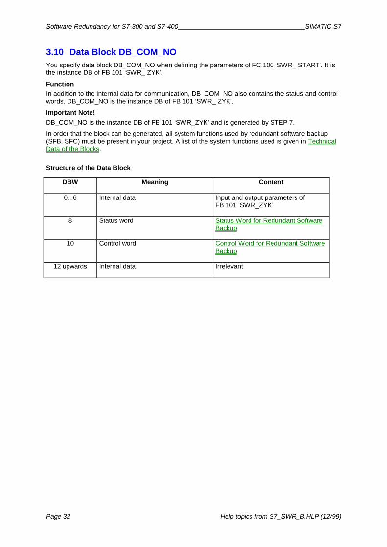
3.10 Data Block DB_COM_NOYou specify data block DB_COM_NO when defining the parameters of FC 100 ‘SWR_ START’. It isthe instance DB of FB 101 ‘SWR_ ZYK’.
FunctionIn addition to the internal data for communication, DB_COM_NO also contains the status and controlwords. DB_COM_NO is the instance DB of FB 101 ‘SWR_ ZYK’.
Important Note!DB_COM_NO is the instance DB of FB 101 ‘SWR_ZYK’ and is generated by STEP 7.
In order that the block can be generated, all system functions used by redundant software backup(SFB, SFC) must be present in your project. A list of the system functions used is given in TechnicalData of the Blocks.
Structure of the Data Block
DBW Meaning Content
0...6 Internal data Input and output parameters ofFB 101 ‘SWR_ZYK’
8 Status word Status Word for Redundant SoftwareBackup
10 Control word Control Word for Redundant SoftwareBackup
12 upwards Internal data Irrelevant

SIMATIC S7 Software Redundancy for SIMATIC S7-300 and S7-400
Help topics from S7_SWR_B.HLP (12/99) Page 33
3.11 Examples Using Minimum Configuration for Quick Introduction
In order to provide a quick introduction, we have provided two example programs on the CD that arecopied to the STEP 7 project directory by the installation program.
The two programs concerned are fully executable examples - one for S7-300 and one for S7-400.The CPU selected in the S7-300 example is the CPU 315-2DP and in the S7-400 example it is theCPU 414-2DP. Both examples use the MPI interfaces of the CPUs for the redundant-backup link.
It goes without saying that you can modify the examples to suit your own requirements and use otherCPUs for example. In such cases, you will need to alter the hardware configuration accordingly.
Hardware Components for S7-300 ExampleA minimal configuration was chosen for the S7-300 example. The two stations consist of one DIN rail,one power supply unit and one CPU 315-2DP in each case. The ET 200M local peripheral deviceconsists of a power supply unit, an IM 153-3 DP slave interface and a simulator module (1 byte inputsand 1 byte outputs, address 0).
Hardware Components for S7-400 ExampleA minimal configuration was chosen for the S7-400 example. The two stations consist of one modulerack, one power supply unit and one CPU 414-2DP in each case. The ET 200M local peripheraldevice consists of a power supply unit, an IM 153-3 DP slave interface and a simulator module(1 byte inputs and 1 byte outputs, address 0).
Hardware Layout for S7-300 and S7-400 Examples
Station A
PS CPU PS
ET 200M
Station B
CPU
MPI(redundant-backup link)
DP Master System 1
DP Master System 1
IM153-3
PSSimulatormodule
Proceed as follows:• Open the example project.• Transfer the ”Hardware Configuration” to Station A and Station B.• Transfer all blocks from the two block containers to the relevant stations.• S7-400 only: transfer the connection configuration to the two stations.
Checking Function Switch the two stations to RUN and check that they are functioning correctly by checking the followingfor each program with the aid of variables table VAT1:
1. Read the status word from Station A (DB5.DBW8).The value 1000 0000 0000 0101 should be displayed. Meaning: station is Subunit A and themaster and all DP slaves are accessible.
2. Read the status word from Station B (DB5.DBW8):The value 1000 0000 0000 1010 should be displayed. Meaning: station is Subunit B and thereserve and all DP slaves are accessible.

Software Redundancy for S7-300 and S7-400 SIMATIC S7
Page 34 Help topics from S7_SWR_B.HLP (12/99)
3. Set the bit in the control word for changeover from master to reserve (DB5.DBX10.0) and thenrecheck the status.Bits DBX 9.0 and DBX 9.1 in the status word on both stations should change status. The activeinterface of the IM 153-3 should also change.

SIMATIC S7 Software Redundancy for SIMATIC S7-300 and S7-400
Help topics from S7_SWR_B.HLP (12/99) Page 35
3.12 Technical Data of the BlocksBlock Memory Requirements System Functions Used
FC 100 ‘SWR_START’ 2.6 kB SFC 22 ‘CREATE_DB’, SFC 5 ‘GADR_LGC’,SFC 50 ‘RD_LGADR’, SFC 46 ‘STP’,SFC 47 ‘WAIT’
FB 101 ‘SWR_ZYK’ 3.7 kB SFC 64 ‘TIME_TCK’, SFB 3 ‘TP’
FC 102 ‘SWR_DIAG’ 2 kB SFC 51 ‘RDSSYST’, SFC 58 ‘WR_REC`,SFC 59 ‘RD_REC’
FB 103 ‘SWR_SFCCOM’ 1.5 kB SFC 20 ‘BLKMOV’, SFC 65 ‘X_SEND’,SFC 66 ’X_RCV’
FB 104 ‘SWR_AG_COM’ 1.5 kB SFC 20 ‘BLKMOV’, FC 5 ‘AG_SEND’,FC 6 ‘AG_RCV’
FB 105 ‘SWR_SFBCOM’ 1.5 kB SFB 12 ‘BSEND’, SFB 13 ‘BRCV’,SFB 23 ‘USTATUS’

Software Redundancy for S7-300 and S7-400 SIMATIC S7
Page 36 Help topics from S7_SWR_B.HLP (12/99)
4 References and Supplementary Information
4.1 Features and Characteristics of Redundant Software BackupThe table below summarizes the most important features.
Feature Description/Explanation
System availability The system consists of two CPUs. One CPU – the master-CPU(master station) – processes the application program and alsotransfers the necessary information for the second CPU – the reserveCPU (reserve station) – to be able to continue running the redundant-backup (section of the) application program in the event of a fault.The reserve station does not process redundant-backup applicationprogram on standby but only the local (non-duplicated) applicationprogram. If the first CPU fails, running of the application program istaken over by the second CPU (master-reserve principle).
Time for transferring updateddata from master to reserveunit
Dependent on the CPU, the network/communication protocol used,and the size of the application program.
See also: Duration of Data Transfer from Master to Reserve
Master-reserve change-overtime
Dependent on the reason for change-over, the time required for datatransfer and the number of DP slaves connected.
See also: Duration of Master-Reserve Change-over
Application program Completely or partially identical application programs possible onboth CPUs
Programming languages LAD, FBD, STL as well as CFC and SCL
Use of standard functionblocks
All function blocks can be usedException: blocks that use S7 timers and/or S7 counters; only IECcounters/timers are permissible.
Use of standard softwarecontrollers
No restriction of SIMATIC S7 standardException: blocks that use S/ timers and/or S7 counters
Alarm processing inapplication program
No restriction of SIMATIC S7 standardAlarms may be lost during master-reserve change-over, however(alarm processing may be suspended)
Number of ET 200M DPslaves usable
Depends on the CPU used(up to 64 ET 200M DP slaves with CPU 414-2DP)
Digital/analog peripherals All digital and analogue modules that can be used on the ET 200Mperipheral unit
Function modules Use of counter module FM 350 possible on ET 200M
Max. volume of redundant-backup data transferable
8 kByte for S7-300
64 kByte for S7-400
Second and third faults Only initial faults are managed, i.e. if a second or third fault occurswhile a fault is being processed it can happen that the redundant-backup program is not processed, for example.

SIMATIC S7 Software Redundancy for SIMATIC S7-300 and S7-400
Help topics from S7_SWR_B.HLP (12/99) Page 37
4.2 Change-over from Master to ReserveDefinition:
If the CPUs change their master/reserve status and the DP slave interfaces their active side, this isreferred to as master-reserve change-over.
Causes of Master-Reserve Change-over
Change-over from master to reserve can take place for a number of reasons as follows:
• Request for change-over from master to reserve at user level (bit set in control word)• Failure of the master unit (POWER OFF or STOP)• Fault on DP master system of master unit• Failure of a redundant-backup DP slave interface
See also:How Does a System with Redundant Software Backup Work? Duration of Master-Reserve Change-over

Software Redundancy for S7-300 and S7-400 SIMATIC S7
Page 38 Help topics from S7_SWR_B.HLP (12/99)
4.3 Duration of Master-Reserve Change-overThe time it takes to change over from master to reserve it the total, in the worst-case scenario, of thefault detection time, the data transfer time and the time taken to switch over the DP slaves.
Worst-case scenario:Duration of master-reserve change-over = Fault detection time
+ Data transfer time+ DP slave switch-over time
See also:Duration of Data Transfer from Master to ReserveSwitch-over Times for ET200M DP SlavesFault Detection Time for Faults on the Redundant-Backup System

SIMATIC S7 Software Redundancy for SIMATIC S7-300 and S7-400
Help topics from S7_SWR_B.HLP (12/99) Page 39
4.3.1 Duration of Data Transfer from Master to ReserveThe time required for data transfer from the master to the reserve unit is dependent on a number offactors as follows:
• Communication performance of the CPU used• Network, connection type used and transmission rate• Volume of data to be transferred
As a rule, it is not possible for all data to be transferred from one station to another within one cycle.In order that the cycle is not overloaded by data transfer, the data is split up and transferred in smallpackets over a number of cycles.
The volume of data transferred is made up of the PIQ area, the bit memory address area and thedata block area specified in FC 100 ‘SWR_START’, as well as other internal data.
Rule of Thumb for Estimating Volume of Data TransferredThe following rule of thumb has proved reliable for estimating the volume of data transferred:Data volume = 3 times the number of output bytes used
The tables below show the typical transmission times for the CPU 315-2DP and the CPU 414-2DP:
Transmission Time for a Redundant-Backup System with Two Type CPU 315-2DP CPUsSince data transmission is organized in 240-byte bocks when using FB 104 ‘SWR_AG_COM’ and in76-byte blocks with FB 103 ‘SWR_SFCCOM’, a maximum of one block can be transferred perredundant-backup software call. This means that the volume of data to be transferred depends on thecall interval of the redundant-backup software.
Transmission time forPROFIBUS (AG_SEND)187.5 kBaud to 1.5 MBaud
Transmission time forIndustrial Ethernet(AG_SEND) 10 MBaud
Transmission time for MPIconnection (XSEND)187.5 kBaud
60 ms per 240-byte block 48 ms per 240-byte block 152 ms per 76-byte block
Note on Table for CPU 315-2DP:The times quoted apply in the case of networks to which only the two stations of the redundant-backup systemare connected. The redundant-backup application program is written in OB 1. The running time of OB 1 is10 ms maximum.If more than 2 nodes are connected to the network, the transmission may be longer than that quoted dependingon the selected baud rate (for 1.5 MBaud and 10 MBaud the transmission time remains virtually constant).
Transmission Time for a Redundant-Backup System With Two Type CPU 414-2DP CPUsNumber ofbytes to betransferred
Transmission time forPROFIBUS/Industrial Ethernet,187.5 kBaud to 12 Mbaud
Transmission time for MPIconnection at 187.5 kBaud
1 kByte 250 ms 340 ms
4 kByte 1 s 1.36 s
16 kByte 4 s 5.44 s
64 kByte 16 s 21.76 s
Note on table for CPU 414-2DP:The times quoted apply in the case of networks to which only the two stations of the redundant-backup systemare connected and communication is processed using the blocks BSEND/BRCV.If more than 2 nodes are connected to the network, the transmission may be longer than that quoted dependingon the selected baud rate.Depending on the communication capacity (K bus) of the CPU, the transmission time may be longer (CPU 412)or shorter (CPU 416).

Software Redundancy for S7-300 and S7-400 SIMATIC S7
Page 40 Help topics from S7_SWR_B.HLP (12/99)
4.3.2 Switch-over Times for ET200M DP SlavesWhen change-over from master to reserve unit takes place, the ET 200M DP slaves areautomatically switched over from the DP master system of the master to the DP master system of thereserve unit. In the case of the S7-300, up to 4 DP slaves can be switched over per call interval andup to 8 DP slaves in the case of the S7-400. If there are more than 4 or 8 DP slaves, they areswitched over in groups over a number of call cycles.
Requirement for Call Interval of OB 1/OB 35The call interval between two OB 1 calls or two timer-controlled OB calls must always be greater thanthe switch-over time for 4 or 8 DP slaves. Only if you are using fewer than 4 or 8 DP slaves, may thecall interval be smaller (see table for times).
CPU 315-2DP with Integrated DP Master
Number ofDP Slaves
CPU consisting of S7-300 with integrated DP Master...12 MBaud 1,5 MBaud 500 kBaud 187,5 kBaud
1 6 ms 6 ms 7 ms 12 ms
2 12 ms 12 ms 14 ms 24 ms
4 25 ms 25 ms 30 ms 50 ms
8 2 x 25 ms 2 x 25 ms 2 x 30 ms 2 x 50 ms
16 4 x 25 ms 4 x 25 ms 4 x 30 ms 4 x 50 ms
32 8 x 25 ms 8 x 25 ms 8 x 30 ms 8 x 50 ms
64 16 x 25 ms 16 x 25 ms 16 x 30 ms 16 x 50 ms
CPUs with Integrated DP Master or CP as DP Master for S7-400 Station
Number ofDP Slaves
CPU consisting of S7-400 with integrated DP Master12 Mbaud 1,5 MBaud 500 kBaud 187,5 kBaud
CP as DP Master (CP 443-5)187,5 kBaud to 12 MBaud
1 5 ms 9 ms 13 ms 20 ms 55 ms
2 10 ms 18 ms 26 ms 40 ms 100 ms
4 20 ms 36 ms 39 ms 80 ms 200 ms
8 40 ms 64 ms 78 ms 160 ms 400 ms
16 2 x 40 ms 2 x 64 ms 2 x 78 ms 2 x 160 ms 2 x 400 ms
32 4 x 40 ms 4 x 64 ms 4 x 78 ms 4 x 160 ms 4 x 400 ms
64 8 x 40 ms 8 x 64 ms 8 x 78 ms 8 x 160 ms 8 x 400 ms

SIMATIC S7 Software Redundancy for SIMATIC S7-300 and S7-400
Help topics from S7_SWR_B.HLP (12/99) Page 41
4.3.3 Fault Detection Time for Faults on the Redundant-backup System
The tables below show the maximum fault detection times of the system and the system response tovarious causes of faults.
Faults on Master UnitCause of Fault Fault Detection
TimeResponse
CPU of master unit in STOPMode or POWER OFF on masterunit
Approx. 1 s* 1. DP interfaces are automatically switchedover to new master
2. Automatic master-reserve change-over
3. Status word indicates “Redundant-backuplink failure”
Failure of DP master on masterunitorFailure of complete DP mastersystem of master unit
a few ms 1. DP interfaces are automatically switchedover to new master
2. Automatic master-reserve change-over
3. Status word indicates “No DP slave present”
* On systems with S7-400 the fault detection time quoted will be reduced from 1 s to 100 ms if the blockpackage BSEND is used and the operating status messages are automatically transferred (must be specifiedin connection configuration).
Faults on Reserve UnitCause of Fault Fault Detection
TimeResponse
CPU of reserve unit in STOPModeorPOWER OFF on reserve unit
Approx. 1 s • No response from master unit;master continues to operate as before
• Status word indicates “Redundant-backuplink failure”
Failure of DP master on reserveunitorFailure of complete DP mastersystem of reserve unit
a few ms • No response from master unit;master continues to operate as before
• Reserve unit status word indicates “No DPslave present”

Software Redundancy for S7-300 and S7-400 SIMATIC S7
Page 42 Help topics from S7_SWR_B.HLP (12/99)
Faults on the Redundant-backup LinkCause of Fault Fault Detection
TimeResponse
Redundant-backup link failure Approx. 1 s** • Both stations become master;DP slaves remain assigned to previousmaster
** In the case of long redundant-backup software call intervals (> 1 s), the detection time for failure of theredundant-backup system is at least 3 to 4 call cycles.
Faults on the Local PeripheralsCause of Fault Fault
Detection TimeResponse
Failure of ET 200M DP interface(IM 153-3) connected to masterunit
A few ms 1. ET 200M DP interface is switched over to thereserve unit
2. All other DP slaves are switched over to thereserve unit
3. Automatic master-reserve change-over
Failure of ET 200M DP interface(IM 153-3) connected to reserveunit
A few ms • No response from master unit;master continues to operate as before
• Reserve unit status word indicates “Not all(i.e. no) DP slaves present”
Failure of ET 200M (IM 153-3)power supply
A few ms 1. All accessible DP slaves are switched over
2. Automatic master-reserve change-over
SIMATIC S7 Software Redundancy for SIMATIC S7-300 and S7-400
Help topics from S7_SWR_B.HLP (12/99) Page 43
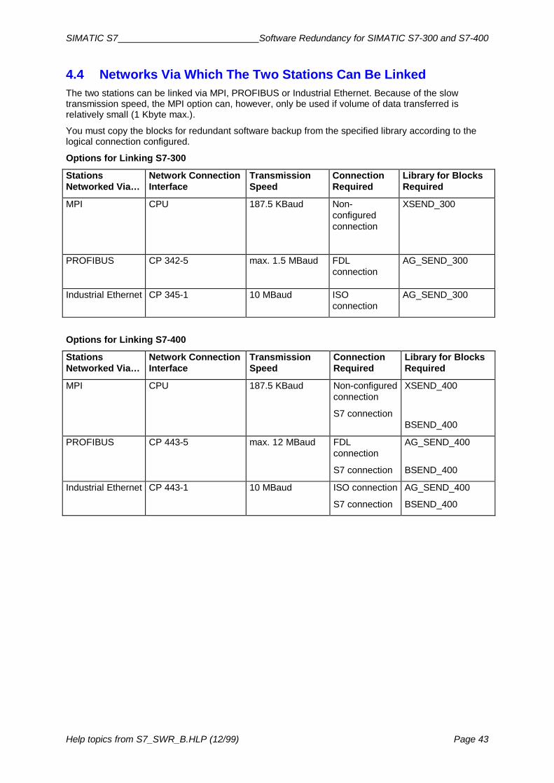
4.4 Networks Via Which The Two Stations Can Be LinkedThe two stations can be linked via MPI, PROFIBUS or Industrial Ethernet. Because of the slowtransmission speed, the MPI option can, however, only be used if volume of data transferred isrelatively small (1 Kbyte max.).
You must copy the blocks for redundant software backup from the specified library according to thelogical connection configured.
Options for Linking S7-300
StationsNetworked Via…
Network ConnectionInterface
TransmissionSpeed
ConnectionRequired
Library for BlocksRequired
MPI CPU 187.5 KBaud Non-configuredconnection
XSEND_300
PROFIBUS CP 342-5 max. 1.5 MBaud FDLconnection
AG_SEND_300
Industrial Ethernet CP 345-1 10 MBaud ISOconnection
AG_SEND_300
Options for Linking S7-400
StationsNetworked Via…
Network ConnectionInterface
TransmissionSpeed
ConnectionRequired
Library for BlocksRequired
MPI CPU 187.5 KBaud Non-configuredconnection
S7 connection
XSEND_400
BSEND_400
PROFIBUS CP 443-5 max. 12 MBaud FDLconnection
S7 connection
AG_SEND_400
BSEND_400
Industrial Ethernet CP 443-1 10 MBaud ISO connection
S7 connection
AG_SEND_400
BSEND_400

Software Redundancy for S7-300 and S7-400 SIMATIC S7
Page 44 Help topics from S7_SWR_B.HLP (12/99)
4.5 Altering Configuration and Application Program in RUN ModeIn order to make alterations while the system is running it is normally necessary to de-activateredundant backup. To do so, you must set the ‘De-activate redundant backup’ bit in the control wordat user level. After that bit has been set, the master unit continues to process the application programas before. In that situation, the master unit has the same characteristics as a standard S7-300 or S7-400 unit.
Once redundant backup has been de-activated, you modify the application program on the reserveunit first and then on the master unit. Once the modified application program has been reloaded ontoboth CPUs, you set the ‘Activate redundant backup’ bit in the control word. After that bit has been set,the redundant-backup link is restored and the system operates with increased availability again.
Changing the extent of the redundant-backup data areas is not possible. Data areas are also changedby a new FB call since this involves creation of a new instance DB. The content of the data can ofcourse be changed if the extent of the data area remains the same. Changing the length of a datablock also alters the extent of the redundant-backup data areas.
Tip: Dimension the data areas generously if you expect to have to extend them once the system isrunning.
The procedures for modifying the program and the configuration of the redundant-backup softwareare described below along with integration mechanisms.
Making Alterations to the Redundant-backup Section of the Program in RUN ModeProceed as follows:
1. De-activate redundant backup (set bit 11.0 of control word)2. Modify and test out application program on reserve CPU.3. Re-activate redundant backup (set bit 11.1 of control word)4. Perform master-reserve change-over if necessary
Result: following master-reserve change-over, the CPU runs the modified application program (andyou can now modify the application program on the second CPU in the same way).
Changing the extent of the redundant-backup data areas is not possible.
Switching Failed ET 200M DP Slave (IM 153-3) Back InProceed as follows:
1. Replace the defective interface module or2. Switch power back on
Result: the redundant-backup software automatically switches the DP slave to the interface modulethat is assigned to the master CPU.
Adding a New ET 200M DP Slave (IM 153-3) in the Redundant-backup SectionProceed as follows:
1. De-activate redundant backup (set bit 11.0 of control word)2. Set the reserve CPU to STOP Mode3. Configure the new DP slave and transfer the hardware configuration.4. Modify the relevant parameters in the call for FC 100 ‘SWR_START’
(PAA_FIRST, PAA_LAST, SLAVE_NO, SLAVE_LEN).5. Delete data blocks DB_WORK_NO, DB_SEND, DB_RCV, DB_A_B_NO, DB_B_A_NO.6. Set this CPU to RUN Mode again (this CPU is using redundant-backup data that has not been
updated)7. Set the other CPU to STOP Mode (the CPU with the new configuration takes over control of the
process)8. Configure the new DP slave and transfer the hardware configuration

SIMATIC S7 Software Redundancy for SIMATIC S7-300 and S7-400
Help topics from S7_SWR_B.HLP (12/99) Page 45
9. Modify the relevant parameters in the call for FC 100 ‘SWR_START’(PAA_FIRST, PAA_LAST, SLAVE_NO, SLAVE_LEN).
10. Delete data blocks DB_WORK_NO, DB_SEND, DB_RCV, DB_A_B_NO, DB_B_A_NO.11. Set this CPU to RUN Mode again.
Result: the new ET 200M DP slave is included in the redundant-backup software.
Note: upgrading without resetting the redundant-backup area is can be performed by means of asecond, separate redundant-backup program with its own data area. That additive redundant-backupprogram then manages the new additional data areas.
Replacing CPU or Upgrading FirmwareProceed as follows:
1. Set the CPU to be replaced to STOP Mode.2. Replace the CPU and transfer the hardware configuration, the application program blocks and
the connection configuration.3. Set that CPU to RUN Mode again.
Result: the new CPU runs as the reserve unit.
Disconnecting and Reconnecting Peripheral ModulesPeripheral modules can be disconnected and reconnected in the same way as with the standard S7.Make sure that a master-reserve change-over does not take place while a module is being replacedby de-activating redundant backup, for example (disabling master-reserve change-over).

Software Redundancy for S7-300 and S7-400 SIMATIC S7
Page 46 Help topics from S7_SWR_B.HLP (12/99)
4.6 Special Feature of Programming in CFCIf you write your application program in CFC, you must invoke the block FC 100 ‘SWR_START’ fromwithin a function block (FB). You must write the necessary program in STL. Only that FB can beentered in the ‘Startup’ group in CFC.
We have provided a ready-made FC in which the necessary program sequence is programmed. It islocated in the ‘Blocks’ container of the S7-400 example application. The function block is called‘FC 99’.
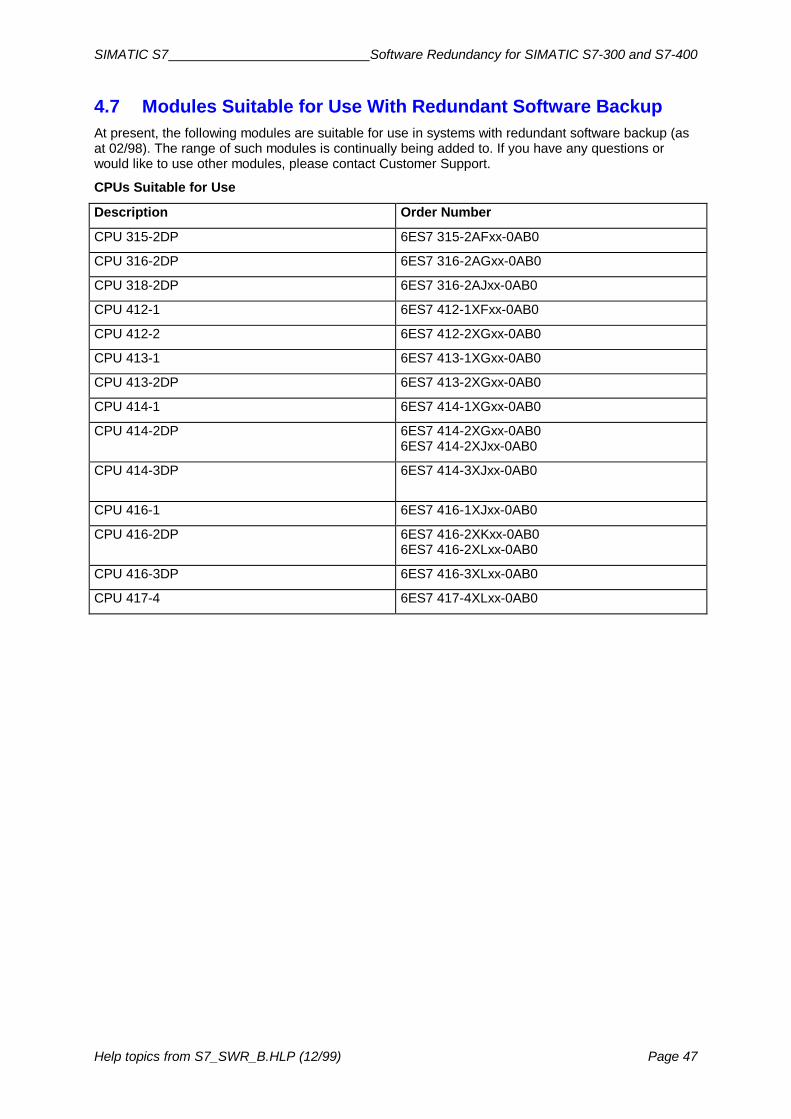
SIMATIC S7 Software Redundancy for SIMATIC S7-300 and S7-400
Help topics from S7_SWR_B.HLP (12/99) Page 47
4.7 Modules Suitable for Use With Redundant Software BackupAt present, the following modules are suitable for use in systems with redundant software backup (asat 02/98). The range of such modules is continually being added to. If you have any questions orwould like to use other modules, please contact Customer Support.
CPUs Suitable for Use
Description Order Number
CPU 315-2DP 6ES7 315-2AFxx-0AB0
CPU 316-2DP 6ES7 316-2AGxx-0AB0
CPU 318-2DP 6ES7 316-2AJxx-0AB0
CPU 412-1 6ES7 412-1XFxx-0AB0
CPU 412-2 6ES7 412-2XGxx-0AB0
CPU 413-1 6ES7 413-1XGxx-0AB0
CPU 413-2DP 6ES7 413-2XGxx-0AB0
CPU 414-1 6ES7 414-1XGxx-0AB0
CPU 414-2DP 6ES7 414-2XGxx-0AB06ES7 414-2XJxx-0AB0
CPU 414-3DP 6ES7 414-3XJxx-0AB0
CPU 416-1 6ES7 416-1XJxx-0AB0
CPU 416-2DP 6ES7 416-2XKxx-0AB06ES7 416-2XLxx-0AB0
CPU 416-3DP 6ES7 416-3XLxx-0AB0
CPU 417-4 6ES7 417-4XLxx-0AB0

Software Redundancy for S7-300 and S7-400 SIMATIC S7
Page 48 Help topics from S7_SWR_B.HLP (12/99)
Communication Modules With DP Master Function Suitable for Use
Description Order Number
Communication module CP 443-5 Extended(for connection to PROFIBUS network)
6EK7 443-5DXxx-0XE0
DP master interface IM 467 or IM 467-FO 6ES7 4675GJxx-0AB06ES7 4675FJxx-0AB0
Suitable Communication Modules for Linking the Stations
Description Order Number
Communication module CP 342-5 6ES7 342-5DA00-0XE0
Communication module CP 343-1 6EK7 343-1BA00-0XE0
Communication module CP 443-5 Extended(for connection to PROFIBUS network)
6EK7 443-5DXxx-0XE0
Communication module CP 443-1 ISO(for connection to Industrial Ethernet)
6EK7 443-1BXxx-0XE0
Suitable Modules for ET 200M Distributed I/O DeviceDescription Order Number
DP slave interface IM 153-3 6ES7 153-3AA00-0XB0 for version 2 or later6ES7 153-3AA01-0XB0
2x DP slave interface IM 153-2 6ES7 153-2AA02-0XB0 for version 2 or later6ES7 153-2AB01-0XB0 for version 2 or later
All digital and analogue modules for ET 200M (See catalogue ST70)
Counter module FM 350 6ES7 350-1AH01-0AE0
CP 341 (20 mA TTY, RS232, RS422/485) 6ES7 341-1xH01-0AE0
SIMATIC S7 Software Redundancy for SIMATIC S7-300 and S7-400
Help topics from S7_SWR_B.HLP (12/99) Page 49
4.8 Communication With Other StationsIt goes without saying that a system with redundant software backup can also communicate with otherstations. The following topics illustrate a number of possible solutions.
Since no communication modules can be used on the ET 200M distributed I/O device,communication must take place via CPs that are used on the CPU.
In order to increase the availability of communication tasks, you must plug in one CP on the station ACPU and one on the station B CPU.
See also:Communication With an S7-300/S7-400 StationCommunication With a Second System with Redundant Software Backup

Software Redundancy for S7-300 and S7-400 SIMATIC S7
Page 50 Help topics from S7_SWR_B.HLP (12/99)
4.8.1 Communication With an S7-300/S7-400 StationConfiguring the Connections with the Standard System
1. Configure one connection from Station A to the target S7-300/400 station.2. Configure one connection from Station B to the target S7-300/400 station.
Application Program for Station A and BIn order that communication failure does not occur, the communication modules must also be runfrom the reserve unit. For that reason, we recommend that you use the following structure for theredundant-backup application program:
CALL FB 101, DB5 DB_WORK_NO :=DB1 CALL_POSITION :=TRUE RETURN_VAL :=MW6 EXT_INFO :=MW8
U DB5.DBX 9.1 SPB M001
Instructions forredundant-backup
application program
M001: CALL FC 1Instructions for
communication program
CALL FB 101, DB5 DB_WORK_NO :=DB1 CALL_POSITION :=FALSE RETURN_VAL :=MW10 EXT_INFO :=MW12
Invoke FB 101 at the beginning of OB 1 or OB 35citing the parameter CALL_POSITION = TRUE..You can process the status and controlinformation in the specified instance DB.
Analyze the status information and program theCPU so that it skips the redundant-backupapplication program when it is running as thereserve unit.
Write your redundant-backup application programhere.
Write your communication program here.
Invoke FB 101 at the end of OB 1 or OB 35 citingthe parameter CALL_POSITION = FALSE. Thisinforms the system that processing of theredundant-backup application program iscomplete.
Cyclic program OB 1 or timer-controlled program OB 35
In FC 1 you program the calls for the communication blocks. Make sure that at least the job numberR_ID is different for Station A and Station B.
The status word should be included in the data area transferred so that the target unit can analyzewhich connection is active. Subsequent analysis of the data received takes place only on the masterunit.
If you write your application program in CFC, you should first program FC 1 in LAD, FBD or STL. Itmust not contain any process variables or message numbers.

SIMATIC S7 Software Redundancy for SIMATIC S7-300 and S7-400
Help topics from S7_SWR_B.HLP (12/99) Page 51
Example of Program Sequence in FC1

Software Redundancy for S7-300 and S7-400 SIMATIC S7
Page 52 Help topics from S7_SWR_B.HLP (12/99)
4.8.2 Communication With a Second System With Redundant Software Backup
Configuring the ConnectionsIn order that the two systems can switch over independently of one another, a total of 4 connectionsmust be configured.
1. Configure two connections from Station A to the redundant-backup system.2. Configure two connections from Station B to the redundant-backup system.
Application Program for Station A and BIn order that communication failure does not occur, the communication modules must also be runfrom the reserve unit. For that reason, we recommend that you use the following structure for theredundant-backup application program:
CALL FB 101, DB5 DB_WORK_NO :=DB1 CALL_POSITION :=TRUE RETURN_VAL :=MW6 EXT_INFO :=MW8
UN DB5.DBX 9.1 SPB M001
Instructions forredundant-backup
application program
M001: CALL FC 1 CALL FC 2
Instructions forcommunication
program
CALL FB 101, DB5 DB_WORK_NO :=DB1 CALL_POSITION :=FALSE RETURN_VAL :=MW10 EXT_INFO :=MW12
Cyclic program OB 1 or timer-controlled program OB 35
Invoke FB 101 at the beginning of OB 1 or OB 35citing the parameter CALL_POSITION = TRUE..You can process the status and control informationin the specified instance DB.
Analyze the status information and program the CPUso that it skips the redundant-backup applicationprogram when it is running as the reserve unit.
Write your redundant-backup application programhere.
Write your communication program here.
Invoke FB 101 at the end of OB 1 or OB 35 citingthe parameter CALL_POSITION = FALSE. Thisinforms the system that processing of the redundant-backup application program is complete.
In FC 1 you program the calls for the communication blocks for station A of the communication peerand in FC 2 you program the calls for the communication blocks for station B of the communicationpeer. Make sure that at least the job number R_ID is different for Station A and Station B.
The status word should be included in the data area transferred so that the target unit can analyzewhich connection is active. Subsequent analysis of the data received takes place only on the masterunit.
If you write your application program in CFC, you should first program FC 1 in LAD, FBD or STL. Itmust not contain any process variables or message numbers.
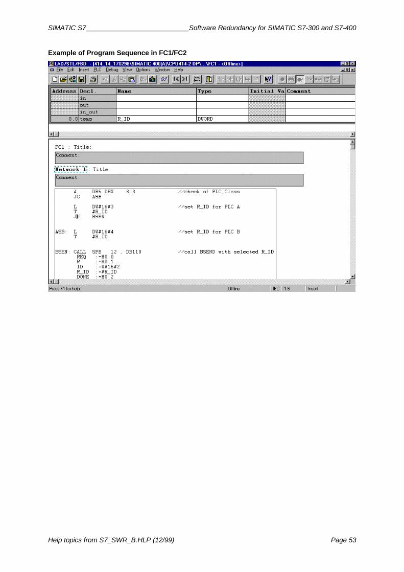
SIMATIC S7 Software Redundancy for SIMATIC S7-300 and S7-400
Help topics from S7_SWR_B.HLP (12/99) Page 53
Example of Program Sequence in FC1/FC2

Software Redundancy for S7-300 and S7-400 SIMATIC S7
Page 54 Help topics from S7_SWR_B.HLP (12/99)
4.9 Standby Concept for Redundant Software BackupIn addition to the standard scenario in which two stations form a master-reserve combination, there isalso another variation referred to as the standby concept.
The term standby concept may be new to you but you are bound to be familiar with the principle ofthe standby concept. You will be familiar with the system used in processes such as motor vehicleproduction whereby a person is kept on standby to step in if any of a particular group of employees isabsent. This is the standby concept we are referring to.
The standby concept for redundant software backup is the same. If any one of a group of stations fails(Station 1 or Station 2 in our diagram), a reserve unit steps in (Station R in our diagram) and takesover the task of the failed unit.
What Are the Important Points to Remember for the Standby Concept?There are basically three requirements for the standby concept:
• There must be a redundant-backup link (connection) between Station 1 and Station R and asecond between Station 2 and Station R.
• The application programs for Station 1 and Station 2 must be loaded on the reserve unit(Station R).
• The reserve unit (Station R) must be able to access the ET 200M distributed I/O devices ofStation 1 and Station 2 (there are two DP masters on Station R).
PROFIBUS-DP (2)
PROFIBUS-DP (1)
Standby Redundant Backup
Station 1
PROFIBUS-DP (2)
PROFIBUS-DP (1)
MPI/PROFIBUS/Ethernet
Reserve Station forStation 1 and 2
Station 2
ET 200M Distributed I/ODevice with IM 153-3
ET 200M Distributed I/ODevice with IM 153-3
Redundant-backup Section 2Redundant-backup Section 1

SIMATIC S7 Software Redundancy for SIMATIC S7-300 and S7-400
Help topics from S7_SWR_B.HLP (12/99) Page 55
4.10 Using Error-Handling OBsIn order that the system does not respond by switching to STOP Mode in the event of errors/events,you should make use of the facility for placing responses in priority classes (organization blocks).
In order to prevent the system responding to failure of a DP slave by switching to STOP Mode, thefollowing error-handling OBs should also be present on the CPU in addition to OB 86 (withFC 102 ‘SWR_DIAG’):
• OB 80 Cycle time overrun can occur during master-reserve change-over• OB 82 Diagnostic alarm from a module on the redundant-backup DP slave interface
(e.g. IM 153-3)• OB 83 Disconnection/reconnection alarm from modules on the DP slave interface• OB 85 Program run error; occurs if a DP slave interface fails• OB 87 Communication fault• OB 122 Peripheral access error (IM 153-3 or module on station has failed)
These OBs allow the application program to respond to the faults concerned. The redundant-backupsoftware does not analyze those OBs nor initiate any subsequent response.
To increase availability, other alarm OBs can also be loaded.

Software Redundancy for S7-300 and S7-400 SIMATIC S7
Page 56 Help topics from S7_SWR_B.HLP (12/99)
5 Example of Redundant Software Backup UsingSIMATIC S7-300
In order to provide as quick and easy an introduction as possible, we have created a specimenproject. That specimen project is ready to run and can also be modified in any way you require.
Based on a simplified model of a road-tunnel monitoring system, it demonstrates how simple thenecessary configuration and programming is. The example is based on two stations with a CPU 315-2DP central processing unit.
Particular operations and settings specific to redundant software backup are dealt with in detail on thefollowing pages. General information that you will already be familiar with from configuring andprogramming an S7-300 or S7-400, such as creating a project or configuring the CPU, is includedonly where it is necessary for an understanding of the examples.
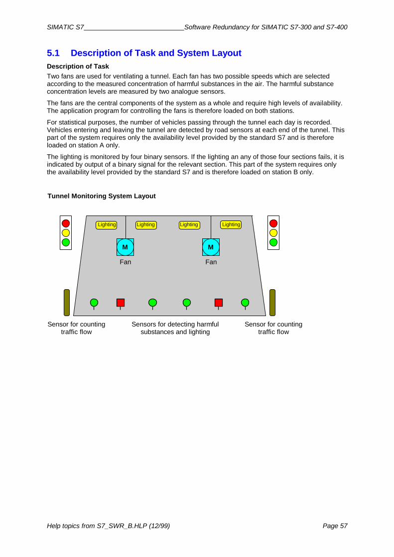
SIMATIC S7 Software Redundancy for SIMATIC S7-300 and S7-400
Help topics from S7_SWR_B.HLP (12/99) Page 57
5.1 Description of Task and System LayoutDescription of TaskTwo fans are used for ventilating a tunnel. Each fan has two possible speeds which are selectedaccording to the measured concentration of harmful substances in the air. The harmful substanceconcentration levels are measured by two analogue sensors.
The fans are the central components of the system as a whole and require high levels of availability.The application program for controlling the fans is therefore loaded on both stations.
For statistical purposes, the number of vehicles passing through the tunnel each day is recorded.Vehicles entering and leaving the tunnel are detected by road sensors at each end of the tunnel. Thispart of the system requires only the availability level provided by the standard S7 and is thereforeloaded on station A only.
The lighting is monitored by four binary sensors. If the lighting an any of those four sections fails, it isindicated by output of a binary signal for the relevant section. This part of the system requires onlythe availability level provided by the standard S7 and is therefore loaded on station B only.
M M
Tunnel Monitoring System Layout
FanFan
Sensors for detecting harmfulsubstances and lighting
Sensor for countingtraffic flow
Sensor for countingtraffic flow
Lighting Lighting Lighting Lighting

Software Redundancy for S7-300 and S7-400 SIMATIC S7
Page 58 Help topics from S7_SWR_B.HLP (12/99)
5.2 Hardware Layout for Example Using S7-300The diagram below shows the hardware layout required. It consists of two S7-300 stations each with aCPU 315-2DP and an ET 200M DP slave. The IM 153-3 DP interface of the ET 200M has oneconnection to the CPU in station A and one to the CPU in station B.
Station A and station B are linked to one another by means of a CP 342-5 connected to a PROFIBUSnetwork.
Hardware Layout for S7-300 Example
PS
Station A (S7-300)
CPU CP PS
Station B (S7-300)
CPU CP
PROFIBUS(redundant-backup link)
DP Master System 1(Station A)
DP MasterSystem 1(Station B)
ET 200M
MPI
OP7 operatorpanel
IM153-3
PS DE DA DE DA Peripheralsfor fans
Peripheralsfor lighting
Peripheralsfor trafficcounter
Hardware UsedThe modules used in the example are detailed in the hardware configuration of the specimen project.

SIMATIC S7 Software Redundancy for SIMATIC S7-300 and S7-400
Help topics from S7_SWR_B.HLP (12/99) Page 59
5.3 Configuring the HardwareIf you wish to check on or alter the hardware configuration of the specimen project, proceed asfollows:
1. Create a project with two stations (e.g. station A and station B) and then open station A.2. Select a module rack from the hardware catalogue.3. Open the module rack (for station A) and insert the power supply unit, the CPU 315-2DP and the
necessary central I/O peripherals.4. Open the second station and repeat steps 2 and 3.5. Drag and drop the IM 153-3 onto the DP master system (“railway line”).6. Insert the ET 200M I/O peripherals.7. Repeat steps 5 and 6 if want to connect more than one ET 200M DP slave to the DP master
system.8. Copy the complete DP branch to the second DP master system.
Rules for Hardware ConfigurationThe configuration of the local peripherals must be identical on both stations. In order that consistencyis maintained, you should always copy the complete DP master system of the first station to the DPmaster system of the second station (even if only minor alterations have been made). To do so youuse the menu command Edit > Insert Redundant Copy.
Using the menu command Edit > Insert Redundant Copy ensures that the peripheral addresses forthe DP slaves are identical on both stations.
Example of Hardware Configuration on Station A and Station B
The screen shot below shows an example of identical hardware configurations on both DP mastersystems.

Software Redundancy for S7-300 and S7-400 SIMATIC S7
Page 60 Help topics from S7_SWR_B.HLP (12/99)
5.4 Configuring the NetworksIf you wish to check on or alter the network configuration of the specimen project, you should observethe instructions below.
What networks are there in a system with redundant software backup?On systems with redundant software backup, a distinction is made between
• the network via which the two stations are linked with one another (also called the network for theredundant backup link); exchange of data between the two stations takes place via this network;
• the PROFIBUS-DP networks to which the DP master systems and local ET200M peripherals areconnected; this network is used by the stations to run the local peripherals.
Network for data exchange between the two stationsThe data that is transferred from the master to the reserve unit can be sent via an MPI, PROFIBUS orindustrial Ethernet.
In our example, the data is exchanged with the aid of communications modules on a PROFIBUSnetwork.
1. Create a PROFIBUS network.2. Connect the CP of station A to the PROFIBUS network and select a node address (e.g.
PROFIBUS address 3).3. Connect the CP of station B to the PROFIBUS network and select a node address (e.g.
PROFIBUS address 4).
PROFIBUS-DP networks for the local peripheralsLocal ET 200M peripherals have two DP interfaces of which one is connected to the DP mastersystem of station A and the other to the DP master system of station B.
Proceed as follows:
1. Create two PROFIBUS-DP networks (for the two DP master systems)2. Select the DP connection of the CPU on station A and connect it to the first PROFIBUS-DP
network.3. Select the DP connection of the CPU on station B and connect it to the second PROFIBUS-DP
network.4. From the hardware catalogue, select the IM 153-3 (located under PROFIBUS-DP in the
ET 200M directory).

SIMATIC S7 Software Redundancy for SIMATIC S7-300 and S7-400
Help topics from S7_SWR_B.HLP (12/99) Page 61
5.5 Configuring the ConnectionsIf you wish to check on or alter the configuration of the connections in the specimen project, youshould observe the instructions below.
A PROFIBUS network with FDL connections was chosen for data exchange between the two stationsin the specimen project.
To create the required logical connection, proceed as follows:
1. Switch from SIMATIC Manager to network view.2. On the menu, select View > DP Slaves so that in Network View the DP slaves are shown as
well.3. Double-click the connections table in network view. Result: a dialog box for defining the connection opens.4. Select the two stations and specify an FDL connection.
Network View Showing DP Slaves and Connections Table

Software Redundancy for S7-300 and S7-400 SIMATIC S7
Page 62 Help topics from S7_SWR_B.HLP (12/99)
5.6 Creating the Application ProgramIf you wish to check on or alter the application program for the specimen project, you should followthe instructions below.
The application program for the S7-300 specimen project consists of
• a redundant-backup program of which there is an identical copy on each of the two stations andwhich runs as part of the timer-controlled program OB 35, and
• two different (non-duplicated) standard application programs, one on each of the two stations,which run as part of the cyclic program OB 1.
Structure of the Application Program
The diagram below illustrates at which points the redundant software backup blocks have to beinvoked.
CALL FC 100 AG_KENNUNG :=’A’ DB_WORK_NO :=DB1 DB_SEND_NO :=DB2 DB_RCV_NO :=DB3 MPI_ADR :=4
etc.
OB 100 Startup Program
CALL FB 101, DB5 DB_WORK_NO :=DB1 CALL_POSITION :=TRUE RETURN_VAL :=MW115 EXT_INFO :=MW117
UN DB5.DBX 8.1 SPB M001
Instructions for redundant-backupapplication program
(program section exists on station Aand station B)
M001: CALL FB 101, DB5 DB_WORK_NO :=DB1 CALL_POSITION :=FALSE RETURN_VAL :=MW119 EXT_INFO :=MW121
FC 101 should be invoked at the beginning of OB 35citing the parameter CALL-POSITION = TRUE.The specified instance DB can be used to processstatus and control information.
Analyse the status information and program the CPUto skip the redundant-backup application programwhen it is acting as the reserve unit.
This is where you insert your redundant-backupapplication program.
FC 101 should be invoked at the end of OB 35 citingthe parameter CALL_POSITION = FALSE. In thisway the system is informed that processing of theredundant-backup application program has beencompleted.
OB 86 Diagnostic Program
OB 35 Timer-controlled Program
CALL FC 102 DB_WORK :=W#16#1 OB86_EV_CLASS :=#OB86_EV_CLASS OB86_FLT_ID :=#OB86_FLT_ID RETURN_VAL :=MW130
.
...
The startup OB should invoke FC 100.FC 100 should then inform the system whichaddresses are to be used for communication andwhich data areas are to be exchanged/updatedbetween the two stations. Data areas are theprocess image of the inputs, bit memory addressareas, data blocks and the instance data blocks forIEC timers/counters.
OB 86 should invoke FC 102 citing the relevantstartup information.This function call is required in order that the systemcan respond automatically to the failure of a DPslave (automatic changeover from master toreserve).

SIMATIC S7 Software Redundancy for SIMATIC S7-300 and S7-400
Help topics from S7_SWR_B.HLP (12/99) Page 63
Block StructureThe screen shot below illustrates the structure of the application program for the S7-300 example.The nesting of the blocks can be seen from that structure.
Application Program RulesThe application program should be set out in such a way that the program for the redundant backupsection is separate from the non-duplicated section.
The redundant-backup section of the program may only use IEC counters and IEC timers. The use ofS7 counters and/or S7 timers is not permitted as those operands can not be exchanged between thetwo stations.
See also:FC 100 ‘SWR_START’FB 101 ‘SWR_ZYK’FC 102 ‘SWR_DIAG’

Software Redundancy for S7-300 and S7-400 SIMATIC S7
Page 64 Help topics from S7_SWR_B.HLP (12/99)
5.7 Connecting Operator Panels and Display UnitsFor visualization of process data and messages, SIMATIC S7 offers a new generation of operatorpanels that is particularly easy to use.
The OP 7 and OP 17 models are particularly suited to use in systems with redundant backup. Bothunits permit manual changeover between multiple stations at the touch of a button. This means youcan switch between operation and monitoring on station A and station B as and when you choose.
In our specimen project we have chosen an OP 7 operator panel for the S7-300 example. The displayfor the status and control words and a number of message texts (relating to the application program)are ready-configured in the specimen project.You can edit the message texts to your own requirements. To configure message texts, you requirethe program ProTool.
See also:Description of operator panels OP 7 and OP 17 and the configuration program ProTool

SIMATIC S7 Software Redundancy for SIMATIC S7-300 and S7-400
Help topics from S7_SWR_B.HLP (12/99) Page 65
6 Example of Redundant Software Backup UsingSIMATIC S7-400
In order to provide as quick and easy an introduction as possible we have created a specimen project.That specimen project is ready to run and can also be modified in any way you require.
Based on a simplified model of a road-tunnel monitoring system, it demonstrates how simple thenecessary configuration and programming is. The example is based on two stations with a CPU 414-2DP central processing unit.
Particular operations and settings specific to redundant software backup are dealt with in detail on thefollowing pages. General information that you will already be familiar with from configuring andprogramming an S7-300 or S7-400, such as creating a project or configuring the CPU, is includedonly where it is necessary for an understanding of the examples.

Software Redundancy for S7-300 and S7-400 SIMATIC S7
Page 66 Help topics from S7_SWR_B.HLP (12/99)
6.1 Description of Task and System LayoutDescription of TaskTwo fans are used for ventilating a tunnel. Each fan has two possible speeds which are selectedaccording to the measured concentration of harmful substances in the air. The harmful substanceconcentration levels are measured by two analogue sensors. The fans are the central components ofthe system as a whole and require high levels of availability. The application program for controllingthe fans is therefore loaded on both stations.
The tunnel has to be closed if the maximum permissible concentration of harmful substances ispresent for more than two minutes. The entrance to the tunnel at each end is controlled by a set oftraffic lights. For safety reasons, this section of the system also requires a high level of availability.
Particular operations and settings specific to redundant software backup are dealt with in detail on thefollowing pages. General information that you will already be familiar with from configuring andprogramming an S7-300 or S7-400, such as creating a project or configuring the CPU, is includedonly where it is necessary for an understanding of the examples.
M M
Tunnel Monitoring System Layout
FanFan
Sensors for detecting harmfulsubstances and lighting
Sensor for countingtraffic flow
Sensor for countingtraffic flow
Lighting Lighting Lighting Lighting

SIMATIC S7 Software Redundancy for SIMATIC S7-300 and S7-400
Help topics from S7_SWR_B.HLP (12/99) Page 67
6.2 Hardware Layout for Example Using S7-400The diagram below shows the hardware layout required. It consists of two S7-400 stations each with aCPU 414-2DP and an ET 200M DP slave. The IM 153-3 DP interface of the ET 200M has oneconnection to the CPU in station A and one to the CPU in station B.
Station A and station B are linked to one another by means of a CP 443-5 connected to a PROFIBUSnetwork.
Hardware Layout for S7-400 Example
Station A (S7-400)
PS CPU CP PS
ET 200M
Station B (S7-400)
CPU CP
PROFIBUS(redundant-backup link)
MPI
Process visualizationusing WINCC
DP Master System 1 (Station A)
DP Master System 1(Station B)
IM153-3
DE DA DEPS DA Peripheralsfor fans andtraffic lights
System Visualization Using WinCCIn the specimen project we have used an operator station for operation and monitoring purposes andfor system visualization.In order to make operation and monitoring as easy as possible for you, we have provided a ready-made screen block for WinCC. You will find the corresponding configuration in the specimen project.
Hardware UsedThe modules used in the example are detailed in the hardware configuration of the specimen project.

Software Redundancy for S7-300 and S7-400 SIMATIC S7
Page 68 Help topics from S7_SWR_B.HLP (12/99)
6.3 Configuring the HardwareIf you wish to check on or alter the hardware configuration of the specimen project, proceed asfollows:
1. Create a project with two stations (e.g. station A and station B) and then open station A.2. Select a module rack from the hardware catalogue.3. Open the module rack (for station A) and insert the power supply unit, the CPU 414-2DP and the
necessary central I/O peripherals.4. Open the second station and repeat steps 2 and 3.5. Drag and drop the IM 153-3 onto the DP master system (“railway line”).6. Insert the ET 200M I/O peripherals.7. Repeat steps 5 and 6 if want to connect more than one ET 200M DP slave to the DP master
system.8. Copy the complete DP branch to the second DP master system.
Rules for Hardware ConfigurationThe configuration of the local peripherals must be identical on both stations. In order that consistencyis maintained, you should always copy the complete DP master system of the first station to the DPmaster system of the second station (even if only minor alterations have been made). To do so youuse the menu command Edit > Insert Redundant Copy.
Using the menu command Edit > Insert Redundant Copy ensures that the peripheral addresses forthe DP slaves are identical on both stations.
Example of Hardware Configuration on Station A and Station B
The screen shot below shows an example of identical hardware configurations on both DP mastersystems.

SIMATIC S7 Software Redundancy for SIMATIC S7-300 and S7-400
Help topics from S7_SWR_B.HLP (12/99) Page 69
6.4 Configuring the NetworksIf you wish to check on or alter the network configuration of the specimen project, you should observethe instructions below.
What networks are there in a system with redundant software backup?On systems with redundant software backup, a distinction is made between
• the network via which the two stations are linked with one another (also called the network for theredundant backup link); exchange of data between the two stations takes place via this network;
• the PROFIBUS-DP networks to which the DP master systems and local ET200M peripherals areconnected; this network is used by the stations to run the local peripherals.
Network for data exchange between the two stationsThe data that is transferred from the master to the reserve unit can be sent via an MPI, PROFIBUS orindustrial Ethernet.
In our example, the data is exchanged with the aid of communications modules on a PROFIBUSnetwork.
1. Create a PROFIBUS network.2. Connect the CP of station A to the PROFIBUS network and select a node address (e.g.
PROFIBUS address 3).3. Connect the CP of station B to the PROFIBUS network and select a node address (e.g.
PROFIBUS address 4).
PROFIBUS-DP networks for the local peripheralsLocal ET 200M peripherals have two DP interfaces of which one is connected to the DP mastersystem of station A and the other to the DP master system of station B.
Proceed as follows:
1. Create two PROFIBUS-DP networks (for the two DP master systems)2. Select the DP connection of the CPU on station A and connect it to the first PROFIBUS-DP
network.3. Select the DP connection of the CPU on station B and connect it to the second PROFIBUS-DP
network.4. From the hardware catalogue, select the IM 153-3 (located under PROFIBUS-DP in the
ET 200M directory).

Software Redundancy for S7-300 and S7-400 SIMATIC S7
Page 70 Help topics from S7_SWR_B.HLP (12/99)
6.5 Configuring the ConnectionsIf you wish to check on the configuration of the connections in the specimen project or if you want tocreate the configuration for the connections yourself, you should observe the instructions below.
A PROFIBUS network with FDL connections was chosen for data exchange between the two stationsin the specimen project.
To create the required logical connection, proceed as follows:
1. Switch from SIMATIC Manager to network view.2. On the menu, select View > DP Slaves so that in Network View the DP slaves are shown as
well.3. Double-click the connections table in network view. Result: a dialog box for defining the connection opens.4. Select the two stations and specify an FDL connection.
Network View Showing DP Slaves and Connections Table

SIMATIC S7 Software Redundancy for SIMATIC S7-300 and S7-400
Help topics from S7_SWR_B.HLP (12/99) Page 71
6.6 Creating the Application ProgramIf you wish to check on or alter the application program for the specimen project, you should followthe instructions below.
The application program for the specimen project consists of a program with full redundant backup.There is an identical copy of the program on each of the two stations and it runs as part of the cyclicprogram OB 1.
Structure of the Application Program
The diagram below illustrates at which points the redundant software backup blocks have to beinvoked.
CALL FC 100 AG_KENNUNG :=’A’ DB_WORK_NO :=DB1 DB_SEND_NO :=DB2 DB_RCV_NO :=DB3 MPI_ADR :=4
etc.
OB 100 Startup Program
CALL FB 101, DB5 DB_WORK_NO :=DB1 CALL_POSITION :=TRUE RETURN_VAL :=MW115 EXT_INFO :=MW117
UN DB5.DBX 8.1 SPB M001
Instructions for redundant-backupapplication program
(program section exists on station Aand station B)
M001: CALL FB 101, DB5 DB_WORK_NO :=DB1 CALL_POSITION :=FALSE RETURN_VAL :=MW119 EXT_INFO :=MW121
FC 101 should be invoked at the beginning of OB 1citing the parameter CALL-POSITION = TRUE.The specified instance DB can be used to processstatus and control information.
Analyse the status information and program the CPUto skip the redundant-backup application programwhen it is acting as the reserve unit.
This is where you insert your redundant-backupapplication program.
FC 101 should be invoked at the end of OB 1 citingthe parameter CALL_POSITION = FALSE. In thisway the system is informed that processing of theredundant-backup application program has beencompleted.
OB 86 Diagnostic Program
OB 1 Cyclic Program
CALL FC 102 DB_WORK :=W#16#1 OB86_EV_CLASS :=#OB86_EV_CLASS OB86_FLT_ID :=#OB86_FLT_ID RETURN_VAL :=MW130
.
...
The startup OB should invoke FC 100.FC 100 should then inform the system whichaddresses are to be used for communication andwhich data areas are to be exchanged/updatedbetween the two stations. Data areas are theprocess image of the inputs, bit memory addressareas, data blocks and the instance data blocks forIEC timers/counters.
OB 86 should invoke FC 102 citing the relevantstartup information.This function call is required in order that the systemcan respond automatically to the failure of a DPslave (automatic changeover from master toreserve).

Software Redundancy for S7-300 and S7-400 SIMATIC S7
Page 72 Help topics from S7_SWR_B.HLP (12/99)
Block StructureThe screen shot below illustrates the structure of the application program for the S7-400 example.The nesting of the blocks can be seen from that structure.
Application Program RulesThe redundant-backup section of the program may only use IEC counters and IEC timers. The use ofS7 counters and/or S7 timers is not permitted as those operands can not be exchanged between thetwo stations.
See also:FC 100 ‘SWR_START’FB 101 ‘SWR_ZYK’FC 102 ‘SWR_DIAG’

SIMATIC S7 Software Redundancy for SIMATIC S7-300 and S7-400
Help topics from S7_SWR_B.HLP (12/99) Page 73
6.7 Connecting Operator Panels and Display UnitsFor visualization of process data and messages, SIMATIC S7 offers a new generation of operatorpanels and display units that is particularly easy to use.
In our specimen project we have chosen an operator station (OS) for system visualization in the S7-400 example. In order to make operation and monitoring using WINCC as easy as possible for you,we have provided a ready-made screen block.
You can use the screen block to perform the following functions from an operator station (OS):
• initiate changeover between master and reserve;• cancel/reactivate redundant backup between master and reserve and view the redundant
backup status;• view the status of the CPU connection (redundant backup link);• view the standby status of the DP slaves.
See also:
Screen Block for Operating and Monitoring Tasks
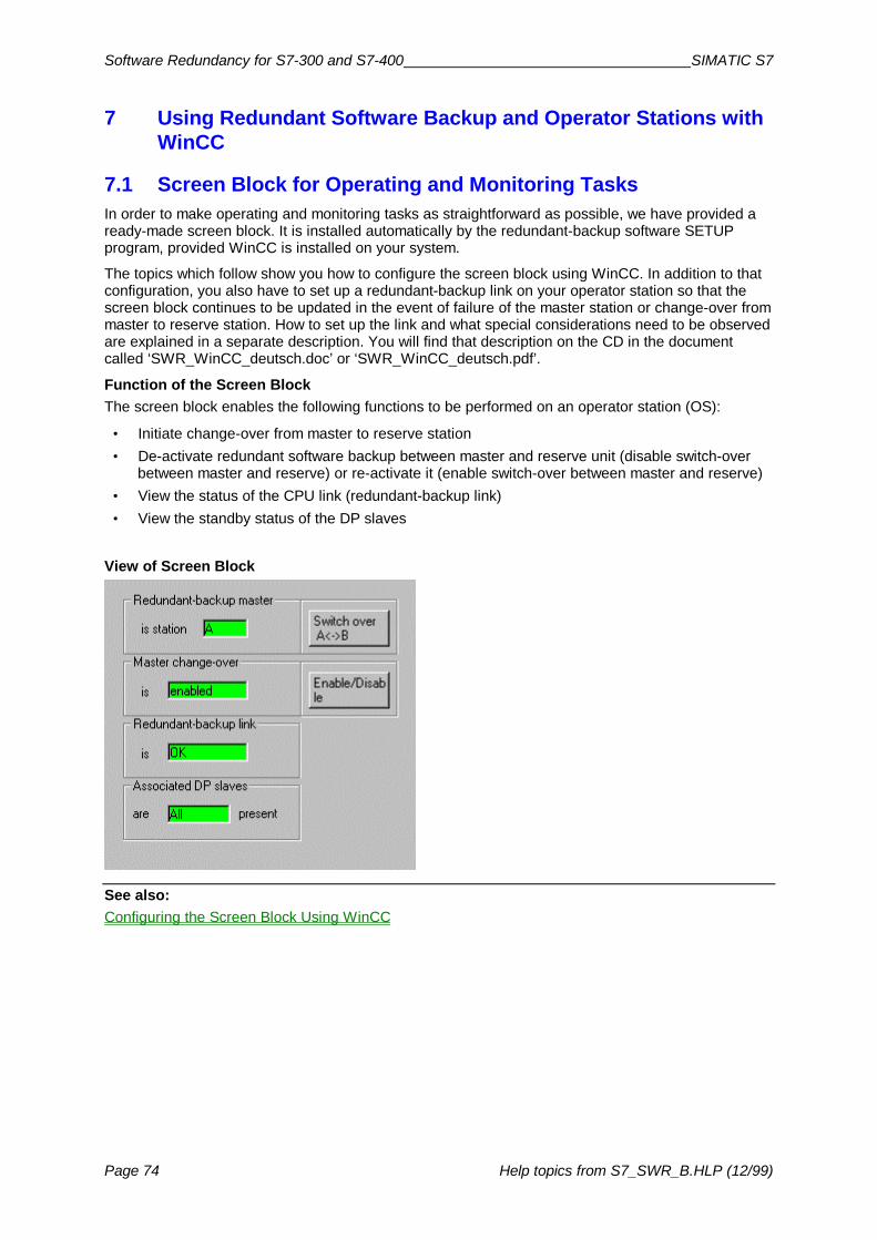
Software Redundancy for S7-300 and S7-400 SIMATIC S7
Page 74 Help topics from S7_SWR_B.HLP (12/99)
7 Using Redundant Software Backup and Operator Stations with WinCC
7.1 Screen Block for Operating and Monitoring TasksIn order to make operating and monitoring tasks as straightforward as possible, we have provided aready-made screen block. It is installed automatically by the redundant-backup software SETUPprogram, provided WinCC is installed on your system.
The topics which follow show you how to configure the screen block using WinCC. In addition to thatconfiguration, you also have to set up a redundant-backup link on your operator station so that thescreen block continues to be updated in the event of failure of the master station or change-over frommaster to reserve station. How to set up the link and what special considerations need to be observedare explained in a separate description. You will find that description on the CD in the documentcalled ‘SWR_WinCC_deutsch.doc’ or ‘SWR_WinCC_deutsch.pdf’.
Function of the Screen BlockThe screen block enables the following functions to be performed on an operator station (OS):
• Initiate change-over from master to reserve station• De-activate redundant software backup between master and reserve unit (disable switch-over
between master and reserve) or re-activate it (enable switch-over between master and reserve)• View the status of the CPU link (redundant-backup link)• View the standby status of the DP slaves
View of Screen Block
See also:Configuring the Screen Block Using WinCC

SIMATIC S7 Software Redundancy for SIMATIC S7-300 and S7-400
Help topics from S7_SWR_B.HLP (12/99) Page 75
7.2 Configuring the Screen Block Using WinCCYou incorporate the screen block into a screen in WinCC. To do so, you must configure the screenblock by means of the appropriate properties dialog boxes.
We recommend you follow the steps below when configuring the screen block:
1. Configuring the Connection for WinCC2. Defining the Variables of the Screen Block3. Inserting the Screen Block in a Screen4. Linking the Display Fields with the Variables (Dynamizing the Screen)

Software Redundancy for S7-300 and S7-400 SIMATIC S7
Page 76 Help topics from S7_SWR_B.HLP (12/99)
7.2.1 Configuring the Connection for WinCCIn order that your WinCC station is linked to the automation system, a connection with the redundant-backup system has to be configured. Only one connection from the operator station to Station A isrequired since the connection with Station B is established by means of the WinCC connectionswitcher.
1. From the Control Center open the directory ‘SIMATIC S7 PROTOCOL SUITE’ (in the container‘Tag Management’).
2. Select the directory in which you wish to create the connection (e.g. MPI).
3. Click the right mouse button and insert a new connection.4. Select the new connection and give it a name, e.g. ‘SW_REDUNDANZ’.5. Click the right mouse button and from the pop-up menu choose Properties.6. Enter the node address of the station to which the connection is to be established (we
recommend you enter the node address of Station A).
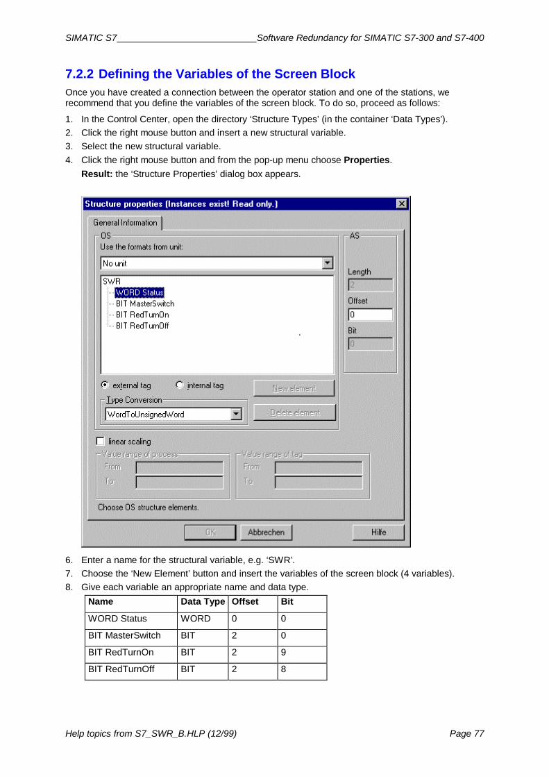
SIMATIC S7 Software Redundancy for SIMATIC S7-300 and S7-400
Help topics from S7_SWR_B.HLP (12/99) Page 77
7.2.2 Defining the Variables of the Screen BlockOnce you have created a connection between the operator station and one of the stations, werecommend that you define the variables of the screen block. To do so, proceed as follows:
1. In the Control Center, open the directory ‘Structure Types’ (in the container ‘Data Types’).2. Click the right mouse button and insert a new structural variable.3. Select the new structural variable.4. Click the right mouse button and from the pop-up menu choose Properties.
Result: the ‘Structure Properties’ dialog box appears.
6. Enter a name for the structural variable, e.g. ‘SWR’.7. Choose the ‘New Element’ button and insert the variables of the screen block (4 variables).8. Give each variable an appropriate name and data type.
Name Data Type Offset Bit
WORD Status WORD 0 0
BIT MasterSwitch BIT 2 0
BIT RedTurnOn BIT 2 9
BIT RedTurnOff BIT 2 8

Software Redundancy for S7-300 and S7-400 SIMATIC S7
Page 78 Help topics from S7_SWR_B.HLP (12/99)
9. In the directory ‘SIMATIC S7 PROTOCOL SUITE’ select the new connection previously inserted(‘SW_REDUNDANZ’).
10. Click the right mouse button and insert a new variable.11. Give the variable a name, e.g. ‘SWR_KESSEL’ and select data type ‘SWR’.12. Specify the number of the instance DB and the offset for the structural variables in the
‘Addresses’ box (offset is DW 8).Result: the screen block now knows which status word and which control bits it should access.

SIMATIC S7 Software Redundancy for SIMATIC S7-300 and S7-400
Help topics from S7_SWR_B.HLP (12/99) Page 79
7.2.3 Inserting the Screen Block in a ScreenTechnically, the screen block is implemented as an OLE Control Element. In order to insert thescreen block in a screen, proceed as follows:
1. In the Control Center, open a screen using the Graphic Designer.2. Select the OLE Control Element using menu command Object Palette > Smart Objects >
OLE Control.3. Click the left mouse button and draw a box into which the screen block is to be inserted.
Result: when you release the mouse button, a window appears for registering the screen block.4. Use the menu command Insert > OLE Control to select the object
‘WinCCSWRedundanzProject.SWRedundanz Control’.Result: the screen block is now visible on the screen and is known to WinCC.

Software Redundancy for S7-300 and S7-400 SIMATIC S7
Page 80 Help topics from S7_SWR_B.HLP (12/99)
7.2.4 Linking the Display Fields with the Variables (Dynamizing the Screen)
Once you have inserted the screen block in the screen, you should link the display fields with thevariables. To do so, proceed as follows (variable names used are examples):
1. Select the screen block.2. Click the right mouse button and choose Properties from the pop-up menu.
Result: the ‘Object Properties’ dialog box appears.
3. In the left-hand box, select ‘OLE Control Properties’4. In the right-hand box, enter the name ‘SWR_TEST’ for the attribute ‘tagname’.5. Click the display icon (light bulb) on the line ‘Status’ and from the selection box that appears,
select ‘SWR_KESSEL.Status’:6. Click the display icon (light bulb) on the line ‘MasterSwitch’ and from the selection box that
appears, select ‘SWR_KESSEL.MasterSwitch’.7. Click the display icon (light bulb) on the line ‘RedTurnOn’ and from the selection box that
appears, select ‘SWR_KESSEL.RedTurnOn’.8. Click the display icon (light bulb) on the line ‘RedTurnOff’ and from the selection box that
appears, select ‘SWR_KESSEL.RedTurnOff’.9. Save the changes in the Graphic Designer.
Result: the screen block is now functional and can be started using ‘WinCC-Runtime’.