Software Modeling & Analysis - Konkukdslab.konkuk.ac.kr/Class/2018/18SMA/Lecture...
53
Software Modeling & Analysis OOPT (Object Oriented Process with Trace) Lecturer: JUNBEOM YOO [email protected]
Transcript of Software Modeling & Analysis - Konkukdslab.konkuk.ac.kr/Class/2018/18SMA/Lecture...
Software Modeling & Analysis
OOPT (Object Oriented Process with Trace)
Lecturer: JUNBEOM [email protected]

What is OOPT?
• OOPT (Object Oriented Process with Trace)
– A software process based on RUP
– Revision of OSP (by Tailored to SE classes in universities)
• Characteristics of OOPT
• 3 Stages
1. Iterative : Multiple development cycles
2. Incremental : System grows incrementally as each cycle is completed
3. Architecture : Stage > Cycle > Phase > Activity
2
Plan andElaboration
Build Deployment1000 2000 3000

1. 3 Stages
• Stage 1000 : Plan and Elaboration
– Planning, defining requirements, building prototyping, etc
– Corresponding to Inception/Elaboration phases in the RUP
• Stage 2000 : Build
– Construction of the system
– Corresponding to Construct phase in the RUP
• Stage 3000 : Deployment
– Implementation of the system into use
– Corresponding to Transition phase in the RUP
3
Plan andElaboration
Build Deployment1000 2000 3000

2. Iterative Development
• Multiple iterations in the Build stage
• Each iteration took about 2 to 8 weeks
4
Cycle 1 Cycle 2 Cycle n...
Plan andElaboration
Build Deployment1000 2000 3000
2100 2200 2n00
Revise Plan
2110 Sync.Artifacts
2120
Analyze
2130
Design
2140
Construct
2150
Test
2160
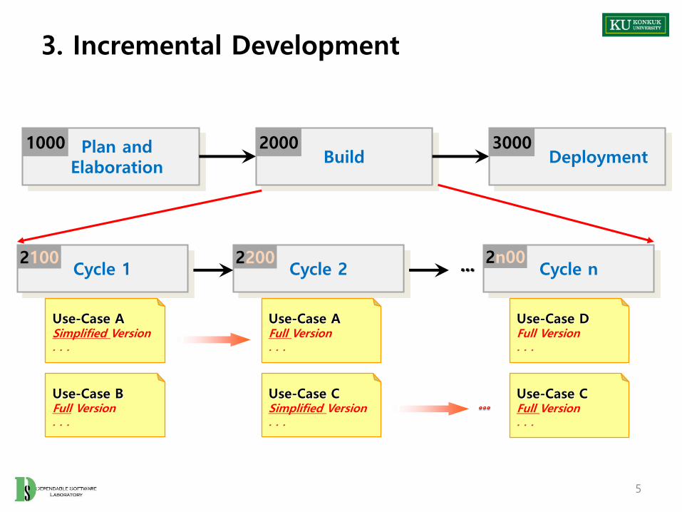
3. Incremental Development
5
Cycle 1 Cycle 2 Cycle n...
Plan andElaboration
Build Deployment1000 2000 3000
2100 2200 2n00
Use-Case ASimplified Version. . .
Use-Case AFull Version. . .
Use-Case DFull Version. . .
Use-Case CFull Version. . .
Use-Case BFull Version. . .
Use-Case CSimplified Version. . .

4. Architecture of OSP
6
DefineReal Use Cases
2141 DefineReports & UI
2142 RefineSystem Archi.
2143 DefineInteraction D.
2144 DefineDesign Class D
2145 DefineDB Schema
2146
Activity
Stage
Cycle 1 Cycle 2 Cycle n...
Plan andElaboration
Build Deployment1000 2000 3000
2100 2200 2n00
Revise Plan
2110 Sync.Artifacts
2120
Analyze
2130
Design
2140
Construct
2150
Test
2160

Phase 2040. Design
Revise Plan
2110 Sync.Artifacts
2120
Analyze
2130
Design
2140
Construct
2150
Test
2160

Phase 2040. Design
• Phase 2040 Activities
8
Define Reports,UI, and Storyboards
2142 RefineSystem Architecture
2143DesignReal Use Cases
2141
DefineInteraction Diagrams
2144
b
Design2140
a. In parallel with interaction diagramsb. Varied order
Define Design Class Diagrams
2145 a
Define Database Schema
2147
DesignTraceability Analysis
2146
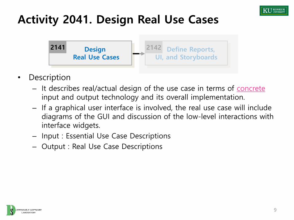
Activity 2041. Design Real Use Cases
• Description
– It describes real/actual design of the use case in terms of concreteinput and output technology and its overall implementation.
– If a graphical user interface is involved, the real use case will include diagrams of the GUI and discussion of the low-level interactions with interface widgets.
– Input : Essential Use Case Descriptions
– Output : Real Use Case Descriptions
9
Define Reports,UI, and Storyboards
2142DesignReal Use Cases
2141

Activity 2041. Design Real Use Cases
• Steps
1. Select each use case from essential use cases
2. Add user interface widgets into the expanded format, and concrete implementation details into the typical courses of events
10
Object Store
End Sale Make PaymentEnter Item
Price
Total
Tendered
Quantity
Descrpt.
Balance
UPC
B
C
D
E
F
G
H I J
A
Window-1

Activity 2041. Design Real Use Cases
11
Use Case Buy Items – Version 1 (Cash only)
Actor Customer, Cashier
Purpose Capture a sale and its cash payment
OverviewA Customer arrives at a checkout with items to purchase. The Cashier records the items and collects cash payment, which may be authorized. On completion, the Customer leaves with the items.
Type Primary and Real
Cross ReferenceFunctions: R1.1, R1.2, R1.3, R1.7, R1.9, R2.1Use Cases: Log In use case
Pre-Requisites N/A
UI Widgets Window-1
Typical Courses of Events
(A) : Actor, (S) : System1. (A) This use case begins when a customer arrives at the POST to checkout with items to purchase.2. (A) For each item, the Cashier types an UPC in A of Window-1. If there is more than one of an
item, the quantity may optionally be entered in E. They press B after each item entry. (E1)3. (S) Adds the item information to the running sales transaction. The description and price of the
current item are displayed in B and F of Window1.4. (A) The Cashier tells the customer the total.
Alternative Courses of Events …
Exceptional Courses of Events E1: If an invalid UPC is entered, indicate an error.

Activity 2042. Define Reports, UI, and Storyboards
• Description
– Design UI storyboard and UI components.
– Input : Requirements Specification, Real Use Case Descriptions
– Output : UI Storyboard, UI Component Design Specification
12
Define Reports,UI, and Storyboards
2142DesignReal Use Cases
2141 RefineSystem Architecture
2143 b

Activity 2043. Refine System Architecture
• Description
– Refine draft system architecture developed in the plan stage
– Input : Draft System Architecture
– Output : A package diagram, a deployment diagram
– Standards Applied
• UML’s Package Diagram
• UML’s Deployment Diagram
13
Define Reports,UI, and Storyboards
2142 RefineSystem Architecture
2143 bDefine
Interaction Diagrams
2144

Activity 2043. Refine System Architecture
• Steps (1~3: Deployment diagram , 4~7: Package diagram)
1. Define a 3-tier layered system architecture
• Presentation Layer : Windows, Reports, and so on
• Application Logic Layer : Tasks and rules that govern the process
• Storage Layer : Persistent storage mechanism
14
ApplicationLogic
Storage
Presentation
Record salesAuthorizepayments
POSTApplet
Database

Activity 2043. Refine System Architecture
2. Decompose the application logic tier into finer layers
• Domain object layer
– Classes representing domain concepts
• Service layer
– Service objects for functions such as database interaction, reporting, communications, security, and so on
15
ApplicationLogic
Storage
Presentation
Database
Sale
POSTApplet
DatabaseInterface ReportGenerator
Payment
“Services Layer”
“Domain Layer”

Activity 2043. Refine System Architecture
3. Assign each tier into different physical computing nodes, and/or different processes
16
ApplicationLogic
Storage
Presentation
Database
Sale
POSTApplet
DatabaseInterface ReportGenerator
Payment
Client computer
ApplicationServer
Data Server

Activity 2043. Refine System Architecture
4. Identify packages
• Place elements together
– that are in the same subject area-closely related by concept or purpose, or that are in a type hierarchy together
– that participate in the same use cases or
– that are strongly associated
17
Core
Products
POST Store Manager
Sales
SalesLineItem
Sale Cashier Customer
ItemProductCatalog
ProductSpecification

Activity 2043. Refine System Architecture
5. Layers of the architecture :
• vertical tiers
Partitions of the architecture :
• horizontal division of relatively parallel subsystems
18
Domain
Services
Core Elements Sales Products
Relational DatabaseInterface
Communication ReportingObject Database
Interface
Vertical
Layers
Horizontal Partitions

Activity 2043. Refine System Architecture
6. Determine package dependencies
• Dependency relationships indicates coupling between packages.
19
Domain
Core Elements Sales
Dependency
Activity 2043. Refine System Architecture
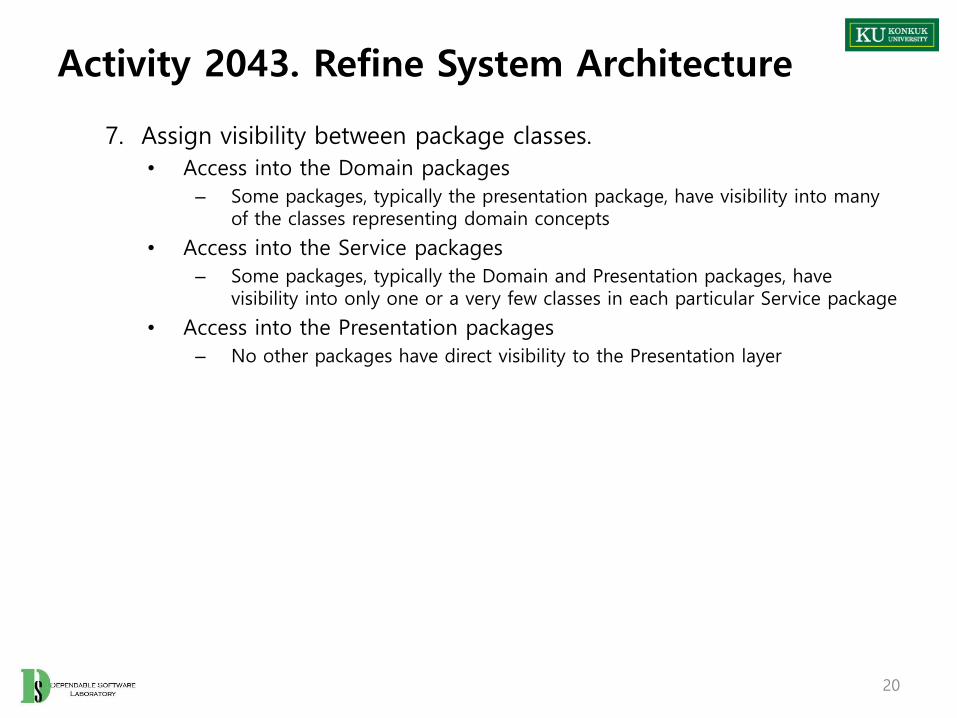
7. Assign visibility between package classes.
• Access into the Domain packages
– Some packages, typically the presentation package, have visibility into many of the classes representing domain concepts
• Access into the Service packages
– Some packages, typically the Domain and Presentation packages, have visibility into only one or a very few classes in each particular Service package
• Access into the Presentation packages
– No other packages have direct visibility to the Presentation layer
20

Activity 2043. Refine System Architecture
21
Domain
RDB Interface Security
Sale
...
...
Payment
...
...
Product Catalog
...
...
Broker
...
...
Proxy
...
...
SecurityFacade
User
...
...
Visibility into many classesfrom other packages.
Visibility into one or only a few classes in each
Service package.
Product Description
...
...
DBFacade
...
addUser(User)...
...
get(id) : Objectsave(Object)...

Activity 2044. Define Interaction Diagrams
• Description
– Collaboration diagrams illustrate object interactions in a graph or network format.
– To illustrate how objects interactions via messages to fulfill tasks.
– Input : Real Use Case Descriptions
– Output : An interaction diagram
– Standards Applied
• UML’s Sequence Diagram or Collaboration Diagram
22
RefineSystem Architecture
2143 bDefine
Interaction Diagrams
2144 Define Design Class Diagrams
2145 a

Activity 2044. Define Interaction Diagrams
• Interaction diagram is a generalization of two more specialized UML diagram types:
– Collaboration diagram
– Sequence diagram
• The both can be used to express similar message interactions
• Collaboration Diagram
– Illustrates object interactions in a graphs or network format
• Sequence Diagram
– Illustrates interactions in a kind of fence format, in which each new object is added to the right.
23
Activity 2044. Define Interaction Diagrams
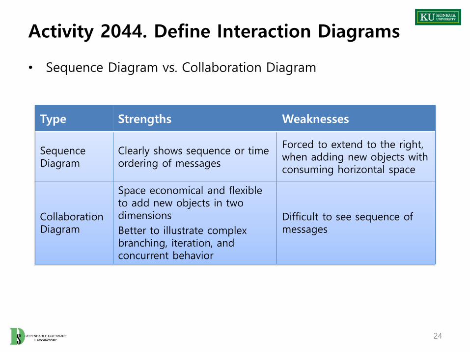
• Sequence Diagram vs. Collaboration Diagram
Type Strengths Weaknesses
SequenceDiagram
Clearly shows sequence or time ordering of messages
Forced to extend to the right, when adding new objects with consuming horizontal space
CollaborationDiagram
Space economical and flexible to add new objects in two dimensions
Better to illustrate complex branching, iteration, and concurrent behavior
Difficult to see sequence of messages
24
Activity 2044. Define Interaction Diagrams
• Steps
1. Draw up actors
2. Deploy objects or classes participating each use case from the real use case descriptions and conceptual class diagram
3. Design a system of interacting objects to fulfill the tasks.
• Regard the use case description as a starting point
25

Activity 2044. Define Interaction Diagrams
• Illustrating Classes and Instances
:Sale
s1:Sale
Sale Class
Instance
Named Instance
26

Activity 2044. Define Interaction Diagrams
• Illustrating Links and Parameters
– A link is a connection path between two instances.
• Illustrating a Return Value
Msg1( )
1: addPayment(amount:Money)
:Sale:POST
Msg1( )
1: tot := total( ): Integer
:Sale:POST
27

Activity 2044. Define Interaction Diagrams
• Message Syntax
– return := message(parameter : parameterType) : returnType
– Standard UML message syntax
• Illustrating Messages to ‘Self’
(‘This’)
Msg1( )
1: addPayment(amount: Money)
:Sale:POST
Msg1( )
:POST
1: clear( )28

Activity 2044. Define Interaction Diagrams
• Illustrating Iterations
– Iteration
– Iteration Clause
Msg1( )
1*: li := nextLineItem( ): SalesLineItem
:Sale:POST
Msg1( )
1*: [i:=1..10] li := nextLineItem( ): SalesLineItem
:Sale:POST
29

Activity 2044. Define Interaction Diagrams
• Illustrating Creation of Instances– Creating message with optional initializing parameters”
• Illustrating Conditional Messages
Msg1( )
1: [new sale] create(cashier):Sale:POST
30

Activity 2044. Define Interaction Diagrams
• Illustrating Message Number Sequencing
– The first message is not numbered
– The order and nesting of subsequent messages are shown with a legal numbering scheme
:ClassB
msg1( )
:ClassA
:ClassC
1: msg2( )
1.1: msg3( )
31

Activity 2044. Define Interaction Diagrams
• Illustrating Mutually Exclusive Conditional Paths
:ClassE
:ClassA
:ClassD
:ClassB
:ClassC
1b: [not test1] msg4( ) 1a.1: msg3( )
1b.1: msg5( )
1a: [test1] msg2( )
msg1( )
2: msg6( )
“ 1a and 1b are mutually exclusive conditional paths”
“ unconditional aftereither msg2 or msg4”
32

Activity 2044. Define Interaction Diagrams
• Illustrating Collections
– A multi-object, or set of instances, may be shown with a stack icon
sales:Sale
33

Activity 2044. Define Interaction Diagrams
• Illustrating Messages to Multi-objects
– A message to a multi-object icon indicates that it is sent to the collection object itself
:Sale
Msg1( )
:SalesLineItem
1: s :=size( ) : int
34

Activity 2044. Define Interaction Diagrams
• Illustrating Messages to a Class Object
– Messages may be sent to a class itself not an instance, in order to invoke class methods
:Sale
Msg1( )
Date
1: d1 := today( ): Date
35

Activity 2045. Define Design Class Diagrams
• Description– Describes more details in conceptual class diagram
– Add navigability, dependency, data type, operation signature, parameters, return types, and so on.
– Input : Interaction Diagram, Conceptual Class Diagram
– Output : A Design Class Diagram
– Standards Applied
• UML’s Class Diagram
36
DefineInteraction Diagrams
2144 Define Design Class Diagrams
2145 a DesignTraceability Analysis
2146

Activity 2045. Define Design Class Diagrams
• Steps
1. Identity all classes
2. Draw them in a class diagram
3. Add attributes
4. Add method names
5. Add type information to the attributes and methods
6. Add the associations
7. Add navigability arrows
8. Add dependency
37

Activity 2045. Define Design Class Diagrams
• Step 1. Identify all classes
– by scanning all interaction diagrams
– listing classes mentioned
POSTSale
ProductCatalogProductSpecification
StoreSalesLineItem
Payment
38

Activity 2045. Define Design Class Diagrams
• Step 2. Draw a class diagram
– includes classes found in Step 1
ProductSpecification
SalesLineItem
Payment
SaleStore
ProductCatalogPOST
39

Activity 2045. Define Design Class Diagrams
• Step 3. Add attributes
– Include the attributes previously identified in the conceptual class diagram that are also used in the design
ProductSpecification
descriptionpriceUPC
SalesLineItem
quantity
Payment
amount
Sale
dateisCompletetime
Store
addressname
ProductCatalog
quantity
POST
40

Activity 2045. Define Design Class Diagrams
• Step 4. Add method names
– Identify method of each class by scanning the interaction diagrams
– The messages sent to a class in interaction diagrams must be defined in the class
– Don’t add
• creation methods and constructors
• accessing methods
• messages to a multiobject
Sale
makeLineitem()
dateisCompletetime
:Sale:POST
3: makeLineItem(spec, qty)
41

Activity 2045. Define Design Class Diagrams
ProductSpecification
descriptionpriceUPC
SalesLineItem
quantity
subtotal( )
Payment
amount
Sale
becomeComplete( )makeLineItem( )makePayment( )total( )
dateisCompletetime
Store
addressname
addSale( )
ProductCatalog
quantity
Specification( )
POST
endSale( )enterItem( )makePayment( )
42

Activity 2045. Define Design Class Diagrams
• Step 5. Add type information
– Show types of attributes, method parameters, and method return values optionally.
– Determine whether to show type information or not
• When using a CASE tool with automatic code generation, exhaustive details are necessary
• If it is being created for software developers to read, exhaustive detail may adversely effect the noise-to-value ratio
43
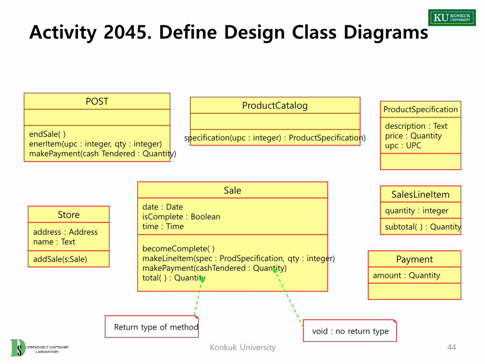
Activity 2045. Define Design Class Diagrams
ProductSpecification
description : Textprice : Quantityupc : UPC
SalesLineItem
quantity : integer
subtotal( ) : Quantity
Payment
amount : Quantity
Store
address : Addressname : Text
addSale(s:Sale)
ProductCatalog
specification(upc : integer) : ProductSpecification)
POST
endSale( )enerItem(upc : integer, qty : integer)makePayment(cash Tendered : Quantity)
Sale
becomeComplete( )makeLineItem(spec : ProdSpecification, qty : integer)makePayment(cashTendered : Quantity)total( ) : Quantity
date : DateisComplete : Booleantime : Time
Return type of method void : no return type
44Konkuk University

• Step 6. Add associations
– Choose associations by software-oriented need-to-know criterion from the interaction diagrams
• Step 7. Add navigability arrows
– According to the interaction diagram
– Common situations to define navigability
• A sends a message to B
• A creates an instance B
• A needs to maintain a connection to B
45Konkuk University
Activity 2045. Define Design Class Diagrams

Activity 2045. Define Design Class Diagrams
POST
endSale( )enerItem( )makePayment( )
Sale
becomeComplete( )makeLineItem( )makePayment( )total()
date isComplete time
1
1
Captures
Absence of navigabilityarrow indicates noconnection from Sale toPOST.
Navigability arrow indicatesPOST objects are connecteduni-directoinally to Saleobject.
POST class will probablyhave an attribute pointing
to a Sale object.
46

Activity 2045. Define Design Class Diagrams
• Step 8. Add dependency relationship
– when there is non-attribute visibility between classes
– Non-attribute visibility : parameter, global, or locally declared visibility
47
ProductSpecification
description : Textprice : Quantityupc : UPC
SalesLineItem
quantity : integer
subtotal( )
Payment
amount : Quantity
Store
address : Addressname : Text
addSale( )ProductCatalog
specification( )
POST
endSale( )enerItem( )makePayment( )
Sale
becomeComplete( )makeLineItem( )makePayment( )total( )
date : DateisComplete : Booleantime : Time
Looks-in
Houses
CapturesContains
Contains
Logs-completed
Paid-by
Describes
1
1
1
11
1
1
1 1..*
1 1..*
1 1
*
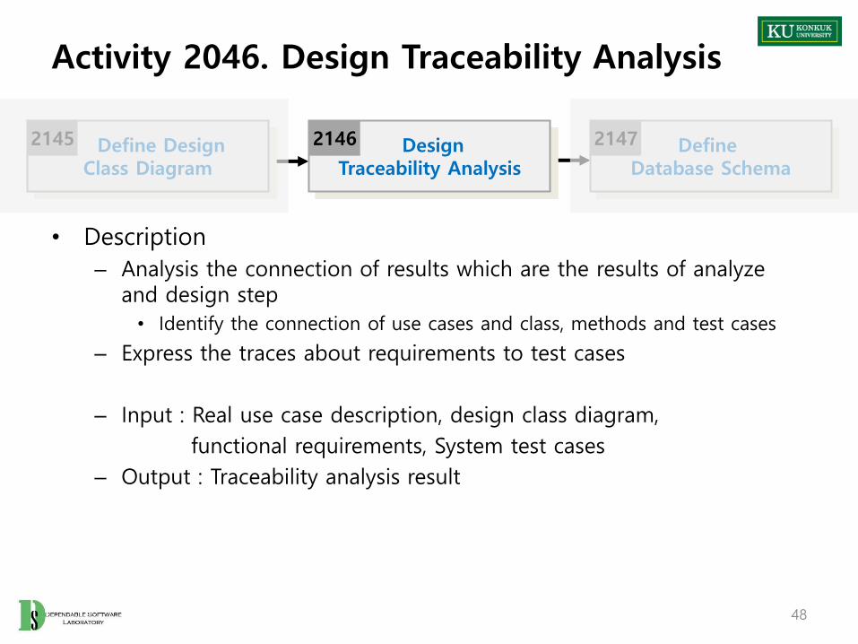
Activity 2046. Design Traceability Analysis
• Description
– Analysis the connection of results which are the results of analyze and design step
• Identify the connection of use cases and class, methods and test cases
– Express the traces about requirements to test cases
– Input : Real use case description, design class diagram,
functional requirements, System test cases
– Output : Traceability analysis result
48
Define DesignClass Diagram
2145 DesignTraceability Analysis
2146 Define Database Schema
2147
Activity 2046. Design Traceability Analysis
• Steps:
1. Identify the related information of essential and real use cases
• 1:1 or more
2. Identify the traces between operation contracts(2036) and operations in interaction diagram(2044)
• Express the direct contacts or hidden contacts
3. Identify the relations of the results of step 2 and class diagram (class, method)
4. Writing the results of the analysis
5. If the operations which are not expressed directly in this step (e.g. GUI related operation like text input), they should be written by 2053
49

Activity 2046. Design Traceability Analysis
• Draw up the traces between operation contracts(2036) and operations in interaction diagram(2044)
– Direct : Operation which is connected directly
– Hidden : Operations which are used to operate the function invisibly
50
HiddenDirect

Activity 2046. Design Traceability Analysis
• The results of step 3 and 4
51
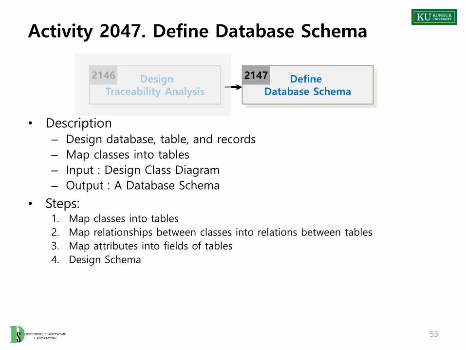
Activity 2047. Define Database Schema
• Description– Design database, table, and records
– Map classes into tables
– Input : Design Class Diagram
– Output : A Database Schema
• Steps:1. Map classes into tables
2. Map relationships between classes into relations between tables
3. Map attributes into fields of tables
4. Design Schema
53
DesignTraceability Analysis
2146 Define Database Schema
2147