Software Management Guide - Proxim Wireless ORiNOCO® 802.11n Access Points - Software Management...
178
ORiNOCO® 802.11n Access Points Software Management Guide Products Covered ORiNOCO® AP-800 ORiNOCO® AP-8000 ORiNOCO® AP-8100
Transcript of Software Management Guide - Proxim Wireless ORiNOCO® 802.11n Access Points - Software Management...

ORiNOCO® 802.11n Access Points
Software Management Guide
Products Covered ORiNOCO® AP-800 ORiNOCO® AP-8000 ORiNOCO® AP-8100

Copyright© 2012 Proxim Wireless Corporation, Milpitas, CA. All rights reserved. Covered by one or more of the following U.S. patents: 5,231,634;5,875,179; 6,006,090; 5,809,060; 6,075,812; 5,077,753. This guide and the software described herein are copyrighted with all rights reserved. Nopart of this publication may be reproduced, transmitted, transcribed, stored in a retrieval system, or translated into any language in any form by anymeans without the written permission of Proxim Wireless Corporation.
TrademarksORiNOCO® and the Proxim logo are the trademarks of Proxim Wireless Corporation. All other trademarks mentioned herein are the property oftheir respective owners.
DisclaimerProxim reserves the right to revise this publication and to make changes in the content from time-to-time without obligation on the part of Proximto provide notification of such revision or change. Proxim may make improvements or changes in the product(s) described in this guide at any time.When using these devices, basic safety precautions should always be followed to reduce the risk of fire, electric shock and injury to persons.
GPL License NoteORiNOCO® products include, in part, some free software that is developed by Free Software Foundation. A user is granted license to this softwareunder the terms of either the GNU General Public License or GNU Lesser General Public License (See http://www.gnu.org/licenses/licenses.html).This license allows the user to freely copy, modify and redistribute this software and no other statement or documentation from us. To get a copy ofthis software or for any other information please contact our customer support team (For telephone numbers, see Telephone Support).
OpenSSL License NoteThis product contains software developed by the OpenSSL Project for use in the OpenSSL Toolkit (http://www.openssl.org/) and that is subject to thefollowing copyright and conditions:
Copyright (c) 1998-2002 The OpenSSL Project. All rights reserved.
The names "OpenSSL Toolkit" and "OpenSSL Project" must not be used to refer to, endorse, or promote the products or for any other purposerelated to the products without prior written permission. For written permission, please contact [email protected].
This software is provided by the OpenSSL Project "as is" and any expressed or implied warranties, including, but not limited to, the impliedwarranties of merchantability and fitness for a particular purpose are disclaimed. In no event shall the OpenSSL Project or its contributors be liablefor any direct, indirect, incidental, special, exemplary, or consequential damages (including, but not limited to, procurement of substitute goods orservices; loss of use, data, or profits; or business interruption) however caused and on any theory of liability, whether in contract, strict liability, ortort (including negligence or otherwise) arising in any way out of the use of this software, even if advised of the possibility of such damage.
ORiNOCO® 802.11n Access Points - Software Management Guide
Documentation Version: 4.1P/N 765-00155, June 2012
ORiNOCO® 802.11n Access Points - Software Management Guide 2
Contents
Preface . . . . . . . . . . . . . . . . . . . . . . . . . . . . . . . . . . . . . . . . . . . . . . . . . . . . . . . . . . . . . . . . . . . . . . 5
1 Introduction . . . . . . . . . . . . . . . . . . . . . . . . . . . . . . . . . . . . . . . . . . . . . . . . . . . . . . . . . . . . . . . . . . 7
Introduction to Wireless Networking . . . . . . . . . . . . . . . . . . . . . . . . . . . . . . . . . . . . . . . . . . . . . . . . . . . . . . . 7
About ORiNOCO® 802.11n Access Points . . . . . . . . . . . . . . . . . . . . . . . . . . . . . . . . . . . . . . . . . . . . . . . . . . . 7
Multiple-Input-Multiple-Output . . . . . . . . . . . . . . . . . . . . . . . . . . . . . . . . . . . . . . . . . . . . . . . . . . . . . . . . . . 10
2 Management and Monitoring Capabilities . . . . . . . . . . . . . . . . . . . . . . . . . . . . . . . . . . . . . . . . 11
Managing and Monitoring Capabilities . . . . . . . . . . . . . . . . . . . . . . . . . . . . . . . . . . . . . . . . . . . . . . . . . . . . 11
3 Device Initialization. . . . . . . . . . . . . . . . . . . . . . . . . . . . . . . . . . . . . . . . . . . . . . . . . . . . . . . . . . . 15
Initialization . . . . . . . . . . . . . . . . . . . . . . . . . . . . . . . . . . . . . . . . . . . . . . . . . . . . . . . . . . . . . . . . . . . . . . . . . 15
Logging onto the Web Interface . . . . . . . . . . . . . . . . . . . . . . . . . . . . . . . . . . . . . . . . . . . . . . . . . . . . . . . . . 18
Home Page . . . . . . . . . . . . . . . . . . . . . . . . . . . . . . . . . . . . . . . . . . . . . . . . . . . . . . . . . . . . . . . . . . . . . . . . . 20
4 Basic Configuration . . . . . . . . . . . . . . . . . . . . . . . . . . . . . . . . . . . . . . . . . . . . . . . . . . . . . . . . . . . 23
Basic Configuration . . . . . . . . . . . . . . . . . . . . . . . . . . . . . . . . . . . . . . . . . . . . . . . . . . . . . . . . . . . . . . . . . . . 23
Factory Default Configuration . . . . . . . . . . . . . . . . . . . . . . . . . . . . . . . . . . . . . . . . . . . . . . . . . . . . . . . . . . . 24
Parameters requiring Reboot . . . . . . . . . . . . . . . . . . . . . . . . . . . . . . . . . . . . . . . . . . . . . . . . . . . . . . . . . . . . 25
5 Device Configuration . . . . . . . . . . . . . . . . . . . . . . . . . . . . . . . . . . . . . . . . . . . . . . . . . . . . . . . . . 27
System . . . . . . . . . . . . . . . . . . . . . . . . . . . . . . . . . . . . . . . . . . . . . . . . . . . . . . . . . . . . . . . . . . . . . . . . . . . . . 28
Network . . . . . . . . . . . . . . . . . . . . . . . . . . . . . . . . . . . . . . . . . . . . . . . . . . . . . . . . . . . . . . . . . . . . . . . . . . . 28
Ethernet . . . . . . . . . . . . . . . . . . . . . . . . . . . . . . . . . . . . . . . . . . . . . . . . . . . . . . . . . . . . . . . . . . . . . . . . . . . 36
Wireless Interface . . . . . . . . . . . . . . . . . . . . . . . . . . . . . . . . . . . . . . . . . . . . . . . . . . . . . . . . . . . . . . . . . . . . 37
Security . . . . . . . . . . . . . . . . . . . . . . . . . . . . . . . . . . . . . . . . . . . . . . . . . . . . . . . . . . . . . . . . . . . . . . . . . . . . 51
Quality of Service (QoS) . . . . . . . . . . . . . . . . . . . . . . . . . . . . . . . . . . . . . . . . . . . . . . . . . . . . . . . . . . . . . . . . 61
Virtual Local Area Network (VLAN) . . . . . . . . . . . . . . . . . . . . . . . . . . . . . . . . . . . . . . . . . . . . . . . . . . . . . . . . 68
Filters . . . . . . . . . . . . . . . . . . . . . . . . . . . . . . . . . . . . . . . . . . . . . . . . . . . . . . . . . . . . . . . . . . . . . . . . . . . . . . 73
DHCP . . . . . . . . . . . . . . . . . . . . . . . . . . . . . . . . . . . . . . . . . . . . . . . . . . . . . . . . . . . . . . . . . . . . . . . . . . . . . 86
6 Device Management . . . . . . . . . . . . . . . . . . . . . . . . . . . . . . . . . . . . . . . . . . . . . . . . . . . . . . . . . . 90
System . . . . . . . . . . . . . . . . . . . . . . . . . . . . . . . . . . . . . . . . . . . . . . . . . . . . . . . . . . . . . . . . . . . . . . . . . . . . . 90
File Management . . . . . . . . . . . . . . . . . . . . . . . . . . . . . . . . . . . . . . . . . . . . . . . . . . . . . . . . . . . . . . . . . . . . . 93
Services . . . . . . . . . . . . . . . . . . . . . . . . . . . . . . . . . . . . . . . . . . . . . . . . . . . . . . . . . . . . . . . . . . . . . . . . . . . 101
Simple Network Time Protocol (SNTP) . . . . . . . . . . . . . . . . . . . . . . . . . . . . . . . . . . . . . . . . . . . . . . . . . . . . 109
Access Control . . . . . . . . . . . . . . . . . . . . . . . . . . . . . . . . . . . . . . . . . . . . . . . . . . . . . . . . . . . . . . . . . . . . . . 110
Reset to Factory . . . . . . . . . . . . . . . . . . . . . . . . . . . . . . . . . . . . . . . . . . . . . . . . . . . . . . . . . . . . . . . . . . . . . 111
7 Device Monitoring. . . . . . . . . . . . . . . . . . . . . . . . . . . . . . . . . . . . . . . . . . . . . . . . . . . . . . . . . . . 113
Interface Statistics . . . . . . . . . . . . . . . . . . . . . . . . . . . . . . . . . . . . . . . . . . . . . . . . . . . . . . . . . . . . . . . . . . . 113
ORiNOCO® 802.11n Access Points - Software Management Guide 3

Station Statistics . . . . . . . . . . . . . . . . . . . . . . . . . . . . . . . . . . . . . . . . . . . . . . . . . . . . . . . . . . . . . . . . . . . . 116
Rogue Scan Statistics . . . . . . . . . . . . . . . . . . . . . . . . . . . . . . . . . . . . . . . . . . . . . . . . . . . . . . . . . . . . . . . . . 118
Bridge . . . . . . . . . . . . . . . . . . . . . . . . . . . . . . . . . . . . . . . . . . . . . . . . . . . . . . . . . . . . . . . . . . . . . . . . . . . . 120
Network Layer . . . . . . . . . . . . . . . . . . . . . . . . . . . . . . . . . . . . . . . . . . . . . . . . . . . . . . . . . . . . . . . . . . . . . . 121
RADIUS . . . . . . . . . . . . . . . . . . . . . . . . . . . . . . . . . . . . . . . . . . . . . . . . . . . . . . . . . . . . . . . . . . . . . . . . . . . 123
Logs . . . . . . . . . . . . . . . . . . . . . . . . . . . . . . . . . . . . . . . . . . . . . . . . . . . . . . . . . . . . . . . . . . . . . . . . . . . . . 126
Console Commands . . . . . . . . . . . . . . . . . . . . . . . . . . . . . . . . . . . . . . . . . . . . . . . . . . . . . . . . . . . . . . . . . 127
SNMP V3 Statistics . . . . . . . . . . . . . . . . . . . . . . . . . . . . . . . . . . . . . . . . . . . . . . . . . . . . . . . . . . . . . . . . . . . 127
8 Troubleshooting . . . . . . . . . . . . . . . . . . . . . . . . . . . . . . . . . . . . . . . . . . . . . . . . . . . . . . . . . . . . 129
Gigabit PoE Injector (Not supplied) . . . . . . . . . . . . . . . . . . . . . . . . . . . . . . . . . . . . . . . . . . . . . . . . . . . . . . . 129
Connectivity Issues . . . . . . . . . . . . . . . . . . . . . . . . . . . . . . . . . . . . . . . . . . . . . . . . . . . . . . . . . . . . . . . . . . 130
Setup and Configuration Problems . . . . . . . . . . . . . . . . . . . . . . . . . . . . . . . . . . . . . . . . . . . . . . . . . . . . . . 132
Recovery Procedures . . . . . . . . . . . . . . . . . . . . . . . . . . . . . . . . . . . . . . . . . . . . . . . . . . . . . . . . . . . . . . . . . 135
Application Specific Troubleshooting . . . . . . . . . . . . . . . . . . . . . . . . . . . . . . . . . . . . . . . . . . . . . . . . . . . . . 141
A Frequency Domains and Channels. . . . . . . . . . . . . . . . . . . . . . . . . . . . . . . . . . . . . . . . . . . . . . 142
B Bootloader CLI and Scan Tool . . . . . . . . . . . . . . . . . . . . . . . . . . . . . . . . . . . . . . . . . . . . . . . . . 151
C ASCII Character Chart . . . . . . . . . . . . . . . . . . . . . . . . . . . . . . . . . . . . . . . . . . . . . . . . . . . . . . . . 153
D Frequently Asked Questions (FAQs) . . . . . . . . . . . . . . . . . . . . . . . . . . . . . . . . . . . . . . . . . . . . 154
E Glossary . . . . . . . . . . . . . . . . . . . . . . . . . . . . . . . . . . . . . . . . . . . . . . . . . . . . . . . . . . . . . . . . . . . 161
F Abbreviations . . . . . . . . . . . . . . . . . . . . . . . . . . . . . . . . . . . . . . . . . . . . . . . . . . . . . . . . . . . . . . 169
G Statement of Warranty . . . . . . . . . . . . . . . . . . . . . . . . . . . . . . . . . . . . . . . . . . . . . . . . . . . . . . 173
H Technical Services and Support . . . . . . . . . . . . . . . . . . . . . . . . . . . . . . . . . . . . . . . . . . . . . . . . 175
ORiNOCO® 802.11n Access Points - Software Management Guide 4

Preface
Preface
About this Guide
This guide gives a jump-start working knowledge on the ORiNOCO® 802.11n Access Points. It explains the step-by-stepprocedure to configure, manage and monitor the device by using Web Interface.
Products Covered
Tabulated below are the ORiNOCO® 802.11n Access Points covered in this guide, with the latest software version supported.
Audience
The intended audience for this guide is the network administrator who configures, manages and/or monitors the device, byusing the Web Interface.
Prerequisites
You should have a basic working knowledge on Wireless Networks, Local Area Networking (LAN) concepts, Network AccessInfrastructures and Client-Server Applications.
Documentation Conventions
Screenshots
This guide uses the screenshots of AP-8100, as a base to explain the step-by-step procedures of configuring, managing andmonitoring the device by using Web Interface. Based on your device, the screenshots may vary. Hence, we request you torefer to the screenshots that are valid for your device.
This chapter contains the information on the following:
• About this Guide• Products Covered• Audience• Prerequisites• Documentation Conventions• Related Documents
Product(s) Software Version Supported
ORiNOCO® AP-800 4.0
ORiNOCO® AP-8000 4.0
ORiNOCO® AP-8100 4.1
ORiNOCO® 802.11n Access Points - Software Management Guide 5

Preface
Device Naming Conventions
Icon Representation
Related Documents
For more information, please refer to the following additional documents that are available at the Proxim’s support sitehttp://support.proxim.com.
• Quick Installation Guide (QIG): A quick reference guide that provides essential information to install and configurethe device.
• Hardware Installation Guide: A guide that provides a hardware overview and details the installation procedures andhardware specifications of ORiNOCO® 802.11n Access Points.
• Reference Guide: A guide that provides essential information on how to configure, manage and monitor the deviceby using Command Line Interface.
• Safety and Regulatory Compliance Guide: A guide that provides essential information on country specific safetyand regulatory norms, to be followed while installing the device.
Naming Convention Description
AP Device Refers to any ORiNOCO® 802.11n AP device(AP-800 / AP-8000 / AP-8100)
AP-800 Refers to the ORiNOCO® AP-800 device
AP-8000 Refers to the ORiNOCO® AP-8000 device
AP-8100 Refers to the ORiNOCO® AP-8100 device
Name Image Meaning
Note A special instruction that draws the attention of the user.
Important A note of significant importance, that a user should beaware of.
Caution A warning, that cautions the user of the possible danger.
: Proxim recommends you to visit its support site http://support.proxim.com for regulatory information and latest product updates.
ORiNOCO® 802.11n Access Points - Software Management Guide 6

ORiNOCO® 802.11n Access Points - Software Management Guide
1
Introduction1.1 Introduction to Wireless NetworkingWireless Networking refers to the technology that enables two or more computers to communicate by using standardnetwork protocols, but without network cabling, generally referred to Wireless LAN (WLAN). A WLAN is grouping of networkcomponents connected by electromagnetic (radio) waves instead of cables. A WLAN basically consists of:
• The network backbone
• End-user devices such as data collection units, handheld computers and laptops
• Wireless LAN Access Points
• Wireless cards
• Software that will help you manage the network.
In a WLAN, an Access Point (AP) Device extends the capability of an existing ethernet network to the devices on a wirelessnetwork, acting as a bridge between the wired and wireless devices.
A wireless network with atleast one AP Device (either connected to a wired network infrastructure or a wireless backhaul)and a set of wireless devices form a Basic Service Set (BSS). Each BSS is identified by a Service Set Identifier (SSID) whichuniquely identifies a WLAN. In a typical network environment, the AP Device functions as a wireless network access point todata and voice networks.
1.2 About ORiNOCO® 802.11n Access PointsProxim’s ORiNOCO® 802.11n Access Point family comprises of the products tabulated below:
This chapter contains information on the following:
• Introduction to Wireless Networking• About ORiNOCO® 802.11n Access Points
— Salient Features— Applications
• Multiple-Input-Multiple-Output
Product(s) Description Image
ORiNOCO® AP-800 Proxim’s ORiNOCO® AP-800 is an indoor 802.11n Access Point withdual-band, 3x3 MIMO (Multiple Input and Multiple Output) and a singleradio which operates either in 2.4 or 5 GHz. This connectorized devicecomes with 3 omni-directional antennas.
ORiNOCO® AP-8000 Proxim’s ORiNOCO® AP-8000 is an indoor 802.11n Access Point withdual-band, 3x3 MIMO (Multiple Input and Multiple Output) and dualradio, where one operates in 2.4GHz and other in 5GHz. Thisconnectorized unit comes with 6 omni-directional antennas, 3 per radio.
ORiNOCO® AP-8100 Proxim’s ORiNOCO® AP-8100 is an indoor 802.11n Access Point withdual-band, 2x2 MIMO (Multiple Input and Multiple Output) and dualradio, where one operates in 2.4GHz and other in 5GHz. This integratedunit comes with built-in 4 omni-directional antennas, 2 per radio.
7

Introduction
1.2.1 Salient Features• Easy operation and installation
• Industry-leading throughput in 802.11b/g/n and 802.11a/n modes in 2.4GHz and 5GHz respectively.
• Highest throughput with single radio rates of 150 - 170 Mbps and dual radio rates of 250 - 300 Mbps.
• Advanced WPA/WPA2 support for enterprise-grade security.
• Wi-Fi certified to interoperate with any Wi-Fi certified client access product.
• Provides wall mounting or ceiling option for flexible device installation.
• Distributed WLANs with Centralized Management.
• Management through a Web Interface (HTTP), Command Line Interface (CLI), Simple Network Management Protocol(SNMP) and Network Management System (ProximVision ES v2.3 and above)
1.2.2 Applications1. Multiple high definition IP-surveillance cameras used for monitoring airports, offices, restaurants, warehouses, etc.,
can be monitored and managed by using a single AP Device.
2. Proxim’s AP Devices exhibit a secure data transfer via high speed network links and over-the-air encryption of data.
3. Enterprise Connectivity:
Delivering a secure, flexible, scalable and reliable enterprise class 802.11n standard Data, Voice, and Video for small and medium Enterprise WLAN deployments, our AP Device can serve multiple service sets with:
— Multiple SSID Assignment: Multiple wireless clients connected to a single AP Device are grouped together as different service sets and every service set is assigned an independent SSID, allowing you to maintain maximum number of groups under a single Virtual Access Point (VAP) network.
— Single SSID Assignment: Different wireless clients belonging to different service sets (SSIDs) can access the wireless network from one single AP Device with a single SSID.
— RADIUS VLAN Assignment: In addition to the manual VLAN assignment, every wireless client / service set connected to a single AP Device is assigned a specific VLAN ID via a pre-configured RADIUS server, reducing the load of manually configuring the VLAN parameters of each wireless client.
Figure 1-1 Enterprise Connectivity (Multiple SSID, Single SSID and RADIUS VLAN Assignment)
ORiNOCO® 802.11n Access Points - Software Management Guide 8

Introduction
4. Seamless client roaming for both data and voice (VoIP):
Multiple wireless clients can connect to a single AP Device, or they can move between multiple AP Devices located within the same vicinity. As wireless devices move from one coverage cell to another, they maintain the network connectivity.
Figure 1-2 Seamless Client Roaming
5. Extended Coverage Areas:
Proxim’s high capacity, 802.11n AP Devices support Wireless Distribution System (WDS), that helps you establish a wireless communication between two AP Devices or two Basic Service Sets (BSS), thus allowing you to extend the WLAN or an access point coverage to wide areas.
Figure 1-3 Extended Coverage Areas - Wireless Distribution Systems
ORiNOCO® 802.11n Access Points - Software Management Guide 9

Introduction
1.3 Multiple-Input-Multiple-OutputORiNOCO® 802.11n AP Devices support Multiple-Input-Multiple-Output (MIMO) antenna technology that uses multipleantennas at both the transmitting end and receiving end to improve communication performance. The underlying technologyof these access point radio(s) are based on a combination of MIMO and OFDM (Orthogonal Frequency Division Multiplexing).MIMO-OFDM combination radios solve interference, fading and multipath problems. Having multiple receivers at thereceiving end, increases the amount of received power and also reduces multipath problems by combining the receivedsignals for each frequency component separately. Hence, MIMO significantly improves the overall gain.
MIMO also uses Spatial multiplexing transmission technique to transmit independent and separately encoded data signalsfrom each of the multiple transmit antennas while reusing or multiplexing in the space dimension. These independent datasignals are called Spatial streams. The transmitting end of the device uses multiple radio Tx chains and signal paths tosimultaneously transmit different data streams, whereas the receiving end combines the Rx signals resulting in higherthroughput.
By increasing the number of receiving and transmitting antennas, the throughput of the channel increases linearly resulting inhigh spectral efficiency.
ORiNOCO® 802.11n Access Points - Software Management Guide 10

ORiNOCO® 802.11n Access Points - Software Management Guide
2
Management and Monitoring Capabilities2.1 Managing and Monitoring CapabilitiesA Network Administrator can use the following interfaces to configure, manage and monitor the device.
• Web (HTTP/HTTPS) Interface
• Command Line Interface (CLI) (Terminal Emulator Programs)
• Simple Network Management Protocol (SNMP) v1/v2c/v3
• ProximVision ES (PVES) [v2.3 and above]
2.1.1 Web (HTTP/HTTPS) Interface
The HTTP interface provides an easy access to configuration settings and network statistics from any computer on thenetwork. You can access the HTTP Interface via your LAN (switch, hub and so on), internet, or with an ethernet cableconnected directly to your computer’s ethernet Port.
HTTPS interface provides an HTTP connection over a Secure Socket Layer (SSL). HTTPS allows the user to access the device ina secure fashion by using SSL over port 443. The device supports SSLv3 with a 128-bit encryption certificate maintained bythe device for secure communication between the device and the HTTP client. All communications are encrypted by using theserver and the client-side certificate.
2.1.2 Command Line Interface (CLI) (Terminal Emulators)
The Command Line Interface (CLI) is a text-based configuration utility that supports a set of keyboard commands andparameters to configure, manage and monitor the device. You can enter command statements, composed of CLI commandsand their associated parameters. Statements may be issued from the keyboard for real time control, or from scripts thatautomate the configuration. For example, when downloading a file, an administrator enters the download CLI Commandalong with the IP Address, file name, and file type parameters.
2.1.2.1 Serial Connection
You can access the CLI over a HyperTerminal serial connection. HyperTerminal is a program that you can use to connect toother Computers, Telnet Sites, Bulletin Board Systems (BBS), Online Services, and Host Computers, by using either a modemor a null modem cable.
If you are using an RS-232 cable, verify the following information in the HyperTerminal serial port setup:
This chapter contains information on the following:
• Managing and Monitoring Capabilities— Web (HTTP/HTTPS) Interface— Command Line Interface (CLI) (Terminal Emulators)— Simple Network Management Protocol (SNMP)v1/v2c/v3— ProximVision ES (PVES)
11

Management and Monitoring Capabilities
:
• If you are using Windows 7 operating system, then use Terminal Emulator programs for serial connection.
• HyperTerminal Serial Connection is not applicable to AP-8100, as it does not have a serial port. However, you can access the CLI via your LAN (switch, hub and so on), internet, or with an ethernet cable connected directly to your computer’s ethernet Port.
2.1.2.2 Telnet
You can access the device through CLI by using Telnet. With Telnet, you can communicate with the device through your LAN(switch, hub and so on), Internet, or with an ethernet cable connected directly to your computer’s ethernet port.
2.1.2.3 Secure Shell (SSH)
You can securely access the device through CLI by using Secure Shell (SSH). The device supports SSH version 2, for secureremote CLI (Telnet) sessions. SSH provides strong authentication and encryption of session data. The SSH server has host keys- a pair of asymmetric keys (a private key that resides on the device) and a public key that is distributed to clients that need toconnect to the device. Clients need to verify that it is communicating with the correct SSH server.
: For details on configuring the device through CLI, please refer to the ORiNOCO® 802.11n Access Points - Reference Guide.
2.1.3 Simple Network Management Protocol (SNMP)v1/v2c/v3
You can also configure, manage and monitor the device by using the Simple Network Management Protocol (SNMP). Thisrequires an SNMP Manager Program (sometimes called MIB browser) or a Network Manager program using SNMP. The devicesupports the following Management Information Base (MIB) files that describe the parameters that can be viewed and/orconfigured over SNMP:
• PXM-SNMP.mib
• RFC-1213.mib
• RFC-1215.mib
• RFC-2571.mib
• RFC-2790.mib
• RFC-3412.mib
• RFC-3414.mib
• IEEE 802.11mib
Port COM1 (default)
Baud Rate 115200
Data 8-bit
Parity None
Stop 1-bit
Flow Control None
ORiNOCO® 802.11n Access Points - Software Management Guide 12

Management and Monitoring Capabilities
The Enterprise MIB defines the read and read-write objects that can be viewed or configured by using SNMP. These objectscorrespond to most of the settings and statistics that are available with the other management interfaces. All Read-Only (RO)and Read-Write (RW) parameters supported by the IEEE802dot11-MIB are as tabulated below.
These MIB files are available on Proxim's website at http://support.proxim.com. You need to compile one or more of theabove MIBs into your SNMP program’s database before you can manage the device by using SNMP. The MIB can be openedwith any text editor, such as Microsoft Word, Notepad, or WordPad.
S.No. MIB Object Name Access(RO / RW)
1 dot11StationID RO
2 dot11PrivacyOptionImplemented RO
3 dot11PowerManagementMode RO
4 dot11DesiredSSID RW
5 dot11DesiredBSSType RO
6 dot11BeaconPeriod RW
7 dot11DTIMPeriod RW
8 dot11MultiDomainCapabilityImplemented RO
9 dot11MultiDomainCapabilityEnabled RO
10 dot11CountryString RO
11 dot11AuthenticationAlgorithmsIndex RO
12 dot11AuthenticationAlgorithm RO
13 dot11AuthenticationAlgorithmsEnable RO
14 dot11MACAddress RO
15 dot11RTSThreshold RW
16 dot11FragmentationThreshold RW
17 dot11ManufacturerID RO
18 dot11ProductID RO
19 dot11ResourceTypeIDName RO
20 dot11manufacturerName RO
21 dot11manufacturerProductName RO
22 dot11PHYType RO
23 dot11CurrentRegDomain RO
24 dot11TempType RO
25 dot11RegDomainsSupportedIndex RO
26 dot11RegDomainsSupportedValue RO
27 dot11SupportedDataRatesTxIndex RO
28 dot11SupportedDataRatesTxValue RO
29 dot11SupportedDataRatesRxIndex RO
30 dot11SupportedDataRatesRxValue RO
31 dot11CurrentFrequency RW
ORiNOCO® 802.11n Access Points - Software Management Guide 13

Management and Monitoring Capabilities
: For details on configuring the device through the SNMP Interface, please refer to the ORiNOCO® 802.11n Access Points - Reference Guide.
2.1.4 ProximVision ES (PVES)
ProximVision ES (commonly known as PVES) is Proxim’s Network Management System that helps to manage and administeryour wireless network effectively and efficiently. ProximVision ES combines industry-leading functionality with an intuitive userinterface, enabling Network Administrators and Help Desk staff to support and control a wireless network.
ProximVision ES offers you a single intelligent console from which you can manage, monitor, analyze and even configure yourdevice. For more information, see ProximVision ES user guide available at http://support.proxim.com.
: You can configure and manage only AP-800 and AP-8000, by using ProximVision ES v2.3 and above.
ORiNOCO® 802.11n Access Points - Software Management Guide 14

ORiNOCO® 802.11n Access Points - Software Management Guide
3
Device Initialization3.1 InitializationYou can initialize the device either through CLI commands, Web Interface or an SNMP Interface.
• To initialize the device by using CLI commands, connect a serial RS-232 cable to the Serial Port of the device.
: AP-8100 does not have a serial port. However, you can initialize, configure, manage and monitor the device through CLI commands via Telnet/SSH.
• To initialize the device by using Web or SNMP interface, connect an ethernet cable to the Ethernet Port of thedevice.
For all the modes of connection, you will need to configure the IP address of the device. As each network is different, asuitable IP address on the network must be assigned to the device. This IP address helps you to configure, manage andmonitor the device through the Web Interface, SNMP, or Telnet/CLI.
The device can either have a static IP or dynamic IP address. By default, the device obtains its IP address automaticallythrough DHCP (dynamic IP address); or else, you must set the IP Address manually (static IP address).
To access the HTTP interface and configure the device, the device must be assigned an IP address, which is valid on itsethernet network. By default, the IP Address type is set to Dynamic. If there is no response from the DHCP server, then thedevice will fall back to the IP Address 169.254.128.132.
3.1.1 ScanTool
Proxim’s ScanTool (Answer ID 1735) is a software utility that runs on Microsoft's Windows machine.
By using ScanTool, you can
• Scan devices within the local IP subnet, which respond to the ScanTool.
: To scan a device in Bootloader mode by using ScanTool, see Bootloader CLI and Scan Tool.
• Obtain device’s IP address
• Modify device’s IP configuration parameters (IP Address, Address Type, Gateway, etc.)
• Switch between the network adapters, if there are multiple network adapters in the system.
• Launch the Web interface.
This chapter contains information on the following:
• Initialization— ScanTool— Initialize the Device by using ScanTool— Modifying the IP Address
• Logging onto the Web Interface• Home Page
— Commit— Reboot
15

Device Initialization
:
• The user may need to disable Windows Firewall for ScanTool to function or to detect the radio.
• ScanTool works only for the Proxim products.
3.1.2 Initialize the Device by using ScanTool
To scan and locate the devices on a network by using ScanTool, do the following:
1. Power on, or reset the device
2. To download Proxim’s ScanTool, log on to Proxim’s support site at http://support.proxim.com and search for ScanToolwith (Answer ID 1735). Upon successful download, double-click the ScanTool icon on the Windows desktop to launchthe program (if the program is not already running).
3. If your computer has more than one network adapter installed, you will be prompted to select the adapter that youwant ScanTool to use. You can use either an ethernet or a wireless adapter. Select an adapter and click OK.
4. The Scan List screen appears.
Figure 3-1 Scan List
5. ScanTool scans the subnet and displays a list of detected devices in the Scan List. You can change your adapter settingat any time by clicking the Select Adapter on the Scan List screen.
6. The screen contains the following information:
• MAC Address
• System Name
• IP Address
• Uptime
• System Description: System Description contains the following information.
— Device Description (ORiNOCO® AP-8100-WD)
— Firmware Version v4.X.Y (v4.1.0)
— Serial Number (SN-SN000000000000121212)
— Bootloader Version (BL-V1.0.2)
ORiNOCO® 802.11n Access Points - Software Management Guide 16

Device Initialization
7. Click Select Adapter, to change the adapter settings.
8. Locate the MAC address of the device you want to initialize from the Scan List and click Web Config to logon to theWeb Interface. See Logging onto the Web Interface
:
• If device does not appear in the Scan List, click Rescan in the Scan List to update. If the device still does not appear in the list, see Troubleshooting.
• Note that after rebooting the device, it may take up to five minutes for the device to appear in the Scan List.
3.1.3 Modifying the IP Address
The IP address assigned to the device can be obtained and, if required, can be changed to the IP address that is appropriateon the network. The ScanTool automatically detects the devices installed on the network segment, regardless of the IPaddress, and enables the configuration of each device’s IP settings
By using ScanTool, you can change the IP address of the device as explained below:
1. Select the device details from the Scan List and click Change. A Change screen appears as shown in the followingfigure.
Figure 3-2 Modifying the IP Address
2. The system automatically generates the MAC address, System Name, TFTP Server IP Address and Image FileName of the device.
3.1.3.1 Assigning the IP Address Manually
1. Select the IP Address Type as Static and enter the appropriate IP Address, Subnet Mask, and the Gateway IPAddress parameters.
2. Enter the SNMP Read/Write password in the Read/Write Password field. By default, it is public.
3. Click OK to save the changes.
4. Click Rescan to verify the changes applied.
ORiNOCO® 802.11n Access Points - Software Management Guide 17
Device Initialization
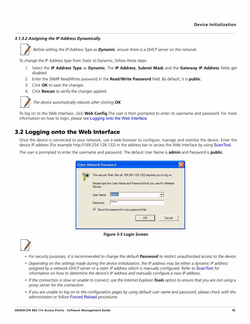
3.1.3.2 Assigning the IP Address Dynamically
: Before setting the IP Address Type as Dynamic, ensure there is a DHCP server on the network.
To change the IP Address type from Static to Dynamic, follow these steps:
1. Select the IP Address Type as Dynamic. The IP Address, Subnet Mask and the Gateway IP Address fields getdisabled.
2. Enter the SNMP Read/Write password in the Read/Write Password field. By default, it is public.
3. Click OK to save the changes.
4. Click Rescan to verify the changes applied.
: The device automatically reboots after clicking OK.
To log on to the Web Interface, click Web Config.The user is then prompted to enter its username and password. For moreinformation on how to login, please see Logging onto the Web Interface
3.2 Logging onto the Web InterfaceOnce the device is connected to your network, use a web browser to configure, manage and monitor the device. Enter thedevice IP address (For example http://169.254.128.132) in the address bar or access the Web Interface by using ScanTool.
The user is prompted to enter the username and password. The default User Name is admin and Password is public.
Figure 3-3 Login Screen
:
• For security purposes, it is recommended to change the default Password to restrict unauthorized access to the device.
• Depending on the settings made during the device initialization, the IP address may be either a dynamic IP address assigned by a network DHCP server or a static IP address which is manually configured. Refer to ScanTool for information on how to determine the device’s IP address and manually configure a new IP address.
• If the connection is slow or unable to connect, use the Internet Explorer Tools option to ensure that you are not using a proxy server for the connection.
• If you are unable to log on to the configuration pages by using default user name and password, please check with the administrator or follow Forced Reload procedures.
ORiNOCO® 802.11n Access Points - Software Management Guide 18

Device Initialization
• If using Internet Explorer, and you enter wrong password consecutively for three times, the HTTP session will get disconnected. If case of other browsers, the login screen will reset until you enter the correct password.
• In the Internet Explorer, to get best results, navigate to Tools > Internet Options > General. Click Settings in the Browsing History and select “Every visit to the webpage”.
Figure 3-4 Internet Explorer Settings
ORiNOCO® 802.11n Access Points - Software Management Guide 19

Device Initialization
3.3 Home PageUpon successful login, the Home Page screen appears.
Figure 3-5 System Summary
The home page contains the following information:
1. Device Description: The device description is displayed on the top-right corner of the home page. It displays thesystem-name, device type, regulatory domain, latest software version supported and firmware version loaded on thedevice.
2. System Summary: The System Summary screen displays the summary of system information such as System Name, IPAddress, Network Mode, Interface Status, MAC Address, Event Log, etc.
3. COMMIT: See Commit4. REBOOT: See Reboot5. HOME: Displays the System Summary Screen.
6. CONFIGURATION: The CONFIGURATION tab allows the user to configure the set of parameters required for a deviceto be operational and establish link in the network. For more details, see Device Configuration.
7. MANAGEMENT: The MANAGEMENT tab allows the user to manage the device. For more details, see DeviceManagement
8. MONITOR: The MONITOR tab allows the user to monitor the device. For more details, see Device Monitoring
3.3.1 Commit
COMMIT operation is used to apply the configuration changes to the device. When changes are made to the configurationparameters of the device, the changes will not take effect, until the COMMIT is clicked. Some parameters may require systemreboot for the changes to take effect. On clicking COMMIT, the system evaluates all the configuration dependencies anddisplays the configuration status.
ORiNOCO® 802.11n Access Points - Software Management Guide 20

Device Initialization
Before applying commit, the system displays a confirmation message, as shown in the following figure:
Figure 3-6 Commit
Click OK, if you wish to commit the changed parameters.
On successful Commit operation, the following screen appears:
Figure 3-7 Commit Status
If the configured parameters requires reboot, on committing the following screen appears.
Figure 3-8 Commit Status with Reboot Message
3.3.2 Reboot
Reboot operation is required for any change in the key parameters to take effect. For example, settings such as configuringthe Radio Mode, IP Address, and Network Mode need reboot to take effect. See Parameters requiring Reboot, for moredetails. On clicking REBOOT, system displays a confirmation window as shown below.
ORiNOCO® 802.11n Access Points - Software Management Guide 21

Device Initialization
Figure 3-9 Reboot
Click OK, if you want to reboot the device.
:
• Every parameter requiring REBOOT upon its configuration, is marked with a red asterisk and it is recommended to reboot the device immediately after modifying a rebootable parameter.
• If the device does not reboot and redirect you to the HOME Page within 2 minutes, then we recommended you to check the network connectivity and try accessing the page later.
ORiNOCO® 802.11n Access Points - Software Management Guide 22

ORiNOCO® 802.11n Access Points - Software Management Guide
4
Basic Configuration4.1 Basic ConfigurationTabulated below are the parameters to be configured to operate the AP device at a basic level:
This chapter contains information on the following:
• Basic Configuration• Factory Default Configuration• Parameters requiring Reboot
Parameter Description
IP Address If you have DHCP Server on your network, then set the Address Type as Dynamic. When setto Dynamic, the device gets its IP Address from the DHCP Server. If there is no response fromthe DHCP Server, then the device will fall back to 169.254.128.132.
If you do not have the DHCP Server on your network, change the Address Type as Static. Fordetails on how to configure the Address Type and the IP address, refer to IP Configuration
Country Code Select a country from the drop down menu. For more details on how to configure theCountry Code, refer to Properties
Radio Mode By default, the radio mode on both Radio1 (Interface1) and Radio 2 (Interface 2) is set toAP. For details on how to configure the radio mode, refer to Properties
Operational Mode Default Operational Mode set on both the radios, is as tabulated below:
For details on how to change the operational mode, refer to Properties
Current Bandwidth By default, the current bandwidth is set to 40 MHz. For details on how to change the currentbandwidth, refer to Properties
: All the interface (radio) 2 parameters discussed in this chapter are applicable only to a dual-radio device.
Device Type Operational Mode
Radio 1 Radio 2
AP-800 802.11g/n Not Applicable
AP-8000 802.11a/n 802.11g/n
AP-8100 802.11a/n 802.11g/n
23

Basic Configuration
Ensure to COMMIT the configured changes and REBOOT the device.
4.2 Factory Default Configuration
SSID Default SSID set on both the radios, is as tabulated below:
For details on how to change SSID, refer to Virtual Access Point (VAP)
Security By default, the security is set to None. For details, refer to Wireless Security
Parameter Default Values
User Name admin
Password public
System Name System-Name
Network Mode Bridge
IP Address Assignment Type Dynamic
Fall Back IP Address 169.254.128.132
Subnet Mask 255.255.0.0
Gateway IP Address 169.254.128.133
Link Integrity Status Disabled
STP Status Disabled
Radio Mode Radio1: APRadio2: AP
Radio Status Enabled
Country Code NoCountry (World Regulatory Domain)US (US Regulatory Domain)JP (JP Regulatory Domain)
Device Type SSID
Radio 1 Radio 2
AP-800 My Wireless Network 1_1 Not Applicable
AP-8000 My Wireless Network 1_1 My Wireless Network 2_1
AP-8100 My Wireless Network 1_1 My Wireless Network 2_1
ORiNOCO® 802.11n Access Points - Software Management Guide 24

Basic Configuration
4.3 Parameters requiring RebootIf you have configured any of the parameters (marked with an asterisk) tabulated below, then reboot the device.
Operational Mode
Current Bandwidth 40 MHz
VAP SSID
Wireless Distribution System (WDS)
Disabled
Local MAC Authentication Disabled
RADIUS MAC Authentication Disabled
RADIUS Accounting Disabled
RADIUS Server Profile Enabled with Profile Name “Default Radius”
VLAN Status Disabled
RADIUS VLAN Status Disabled
Security Profile Name AP Security
QoS Profile Name Default
Security Auth Mode None
Global Filtering Disabled
Proxy ARP Status Disabled
Packet Forwarding Disabled
DHCP Server Status Disabled
SNMP Management Interface Enabled with SNMPv1-v2c
Telnet Management Interface Enabled with login “admin” and password “public”
Device Type
Operational Mode (Supported Frequency Band)
Radio 1 Radio 2
AP-800 802.11g/n (2.4 GHz) Not Applicable
AP-8000 802.11a/n (5 GHz) 802.11g/n (2.4 GHz)
AP-8100 802.11a/n (5 GHz) 802.11g/n (2.4 GHz)
Device Type
SSID
Radio 1 Radio 2
AP-800 My Wireless Network 1_1 Not Applicable
AP-8000 My Wireless Network 1_1 My Wireless Network 2_1
AP-8100 My Wireless Network 1_1 My Wireless Network 2_1
ORiNOCO® 802.11n Access Points - Software Management Guide 25

Basic Configuration
Parameter(s) Web Page(s)
Address Type
CONFIGURATION - > Network - > IP Configuration
IP Address
Subnet Mask
Gateway IP Address
DNS Primary IP and Secondary IP Address
Radio Mode
CONFIGURATION - > Wireless - > Interface 1/ Interface 2 - > PropertiesCountry Code
Operational Mode
Current Bandwidth
Frequency Extension CONFIGURATION - > Wireless - > Interface 1/ Interface 2 - > 11nProperties
Update Firmware (HTTP / TFTP) MANAGEMENT - > File Management - > Update Firmware
Update Configuration (HTTP / TFTP)
MANAGEMENT - > File Management - > Update Configuration
Password
MANAGEMENT - > Services - > HTTP / HTTPSHTTP
HTTP Port
HTTPS
Password
MANAGEMENT - > Services - > Telnet / SSH
Telnet
Telnet Port
Telnet Sessions
SSH
SSH Port
SSH Sessions
SNMP
MANAGEMENT - > Services - > SNMPVersion
Read Password
Read / Write Password
Access Table Status MANAGEMENT - > Access Control
ORiNOCO® 802.11n Access Points - Software Management Guide 26

ORiNOCO® 802.11n Access Points - Software Management Guide
5
Device ConfigurationNote that you can also configure the device by using CLI and SNMP interfaces. Hence, we recommend you to also refer theORiNOCO® 802.11n Access Points - Reference Guide.
This chapter explains the step-by-step procedure to configure the following features on the device, by using WebInterface:
• System• Network
— IP Configuration— Link Integrity— Spanning Tree Protocol (STP)
• Ethernet• Wireless Interface
— Interface 1— Properties— 11n Properties— Virtual Access Point (VAP)
— Interface 2• Security
— Wireless Security— RADIUS— MAC Access Control
• Quality of Service (QoS)— Enhanced Distributed Channel Access (EDCA)— 802.1d to IP DSCP— 802.1d to 802.1p— QoS Profile— QoS Policy
• Virtual Local Area Network (VLAN)— VLAN Ethernet Configuration
• Filters— Protocol Filters— Static MAC Address Filters— Advanced Filters— TCP/UDP Port Filters— Storm Threshold Filters— Packet Forwarding
• DHCP— DHCP Server
27

Device Configuration
5.1 SystemThe System feature enables you to configure system specific information. Navigate to CONFIGURATION > System. The System screen appears.
Figure 5-1 System
Tabulated below are ‘System’ parameters and the method to configure the configurable parameters:
Click OK and COMMIT, to save the configured parameters.
5.2 NetworkThe Network feature displays the network specific information of the device.
To view the network mode, navigate to CONFIGURATION > Network. The Network Configuration screen appears.
Figure 5-2 Network Configuration
The device supports only Bridge mode.
5.2.1 IP Configuration
The IP Configuration feature enables you to configure the TCP/IP settings of the device on a network. Navigate toCONFIGURATION > Network > IP Configuration. The Network IP Configuration screen appears.
Parameter Description
System Name Specifies the name assigned to the device. To assign a name to the device, enter a name inthe System Name box. You can enter a name of maximum 64 characters.
Network Mode Specifies the network mode of the device. The device supports only Bridge mode.
: All the interface (radio) 2 parameters discussed in this chapter are applicable only to a dual-radio device.
ORiNOCO® 802.11n Access Points - Software Management Guide 28

Device Configuration
Figure 5-3 Network IP Configuration
Tabulated below are ‘Network IP’ parameters and the method to configure the configurable parameters:
Parameter Description
Address Type By default this parameter is set to Dynamic. When set to dynamic, the device will obtain IPsettings from a network Dynamic Host Configuration Protocol (DHCP) server automaticallyduring the boot-up.
If you do not have a DHCP server or if you want to manually configure the device IP address,set this parameter to Static.
IP Address Specifies the IP Address of the device. When the address type is set to Dynamic, thisparameter is read-only and displays the device’s current IP address obtained from the DHCPserver. The device will be set to the default IP address 169.254.128.132, if the device cannotobtain the IP address from a DHCP server.
If the Address Type is set to Static then you will have to manually enter the IP Address in theIP Address box.
Subnet Mask Specifies the device subnet mask. When the address type is set to Dynamic, this parameteris read-only and displays the device current subnet mask obtained from the DHCP server. Thedevice will be set to the default subnet mask 255.255.0.0, if the device cannot obtain thesubnet mask from a DHCP server.
If the Address Type is set to Static then you will have to manually enter the subnet mask inthe Subnet Mask box.
Gateway IP Address Specifies the IP address of the device gateway. When address type is set to Dynamic, thisparameter is read-only and displays the IP address of the device gateway. The device will beset to the default Gateway IP address 169.254.128.133, if it cannot obtain the gateway IPaddress from a DHCP server.
If the Address Type is set to Static then you will have to manually enter the gateway IPaddress in the GateWay IP Address box.
ORiNOCO® 802.11n Access Points - Software Management Guide 29

Device Configuration
Click OK and COMMIT, to save the configured parameters.
: If you have changed any of the TCP/IP parameters, then reboot the device.
5.2.2 Link Integrity
Link Integrity helps you to check connectivity between the AP device and its pre-configured servers (routers, gatewaydevices and other devices in the vicinity), by sending ICMP (Internet Control Message Protocol) echo probes periodically. If thedevice receives an acknowledgment from a server within the configured time interval, then the link between that server andthe AP device is active and the link integrity status is set to UP, otherwise it is set to DOWN.
If atleast one server responds back, then the over all Link Status is set to UP and the device performs standard AP functionality.If all the servers configured fail to respond, then the over all Link Status is set to DOWN and all the VAPs enabled in AP modeare disabled. (VAPs in WDS mode remain unaffected. See Virtual Access Point (VAP)). The VAPs in AP mode resume as LinkStatus is set to UP.
Navigate to CONFIGURATION > Network > Link Integrity. The Link Integrity screen appears.
Figure 5-4 Link Integrity
Primary IP Address Specifies the IP Address of the Primary DNS Server. When the address type is set toDynamic, this parameter is read-only and displays the DNS Primary IP Address obtained fromthe DHCP server.
If the Address Type is set to Static then you will have to manually enter the IP Address in thePrimary IP Address box.
Secondary IP Address
Specifies the IP Address of the Secondary DNS Server. When the address type is set toDynamic, this parameter is read-only and displays the DNS Secondary IP Address obtainedfrom the DHCP server.
If the Address Type is set to Static then you will have to manually enter the IP Address in theSecondary IP Address box.
ORiNOCO® 802.11n Access Points - Software Management Guide 30
Device Configuration
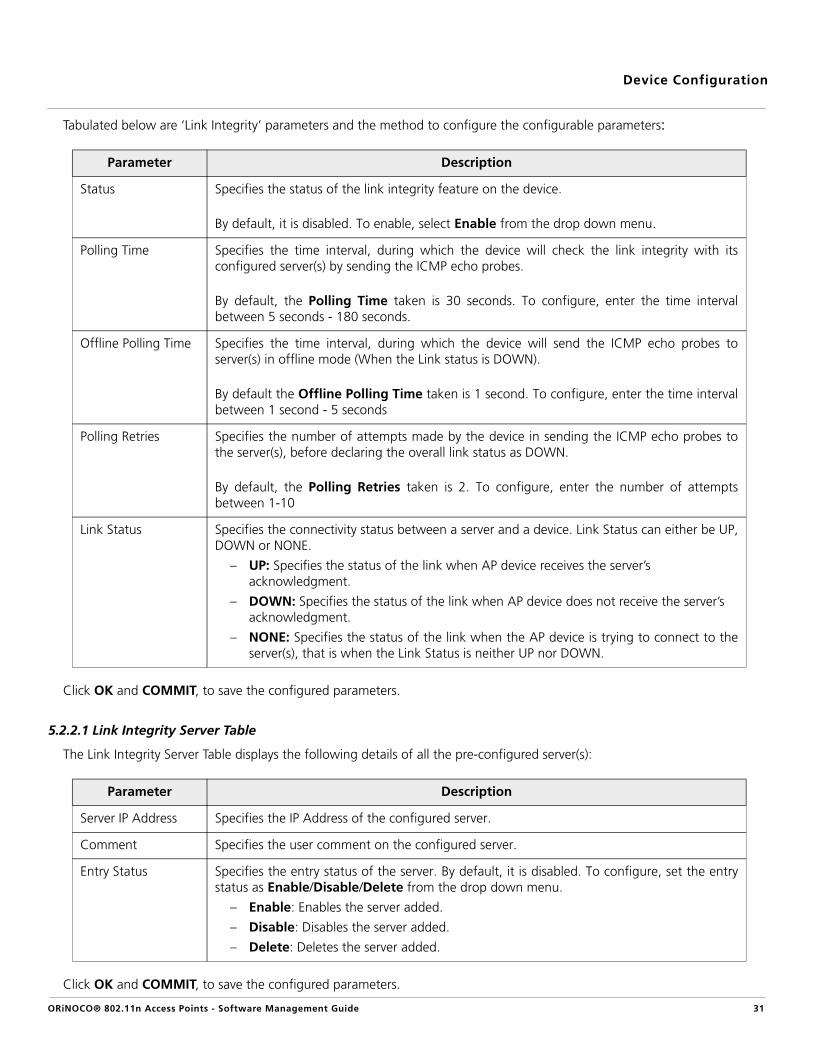
Tabulated below are ‘Link Integrity’ parameters and the method to configure the configurable parameters:
Click OK and COMMIT, to save the configured parameters.
5.2.2.1 Link Integrity Server Table
The Link Integrity Server Table displays the following details of all the pre-configured server(s):
Click OK and COMMIT, to save the configured parameters.
Parameter Description
Status Specifies the status of the link integrity feature on the device.
By default, it is disabled. To enable, select Enable from the drop down menu.
Polling Time Specifies the time interval, during which the device will check the link integrity with itsconfigured server(s) by sending the ICMP echo probes.
By default, the Polling Time taken is 30 seconds. To configure, enter the time intervalbetween 5 seconds - 180 seconds.
Offline Polling Time Specifies the time interval, during which the device will send the ICMP echo probes toserver(s) in offline mode (When the Link status is DOWN).
By default the Offline Polling Time taken is 1 second. To configure, enter the time intervalbetween 1 second - 5 seconds
Polling Retries Specifies the number of attempts made by the device in sending the ICMP echo probes tothe server(s), before declaring the overall link status as DOWN.
By default, the Polling Retries taken is 2. To configure, enter the number of attemptsbetween 1-10
Link Status Specifies the connectivity status between a server and a device. Link Status can either be UP,DOWN or NONE.
– UP: Specifies the status of the link when AP device receives the server’s acknowledgment.
– DOWN: Specifies the status of the link when AP device does not receive the server’s acknowledgment.
– NONE: Specifies the status of the link when the AP device is trying to connect to theserver(s), that is when the Link Status is neither UP nor DOWN.
Parameter Description
Server IP Address Specifies the IP Address of the configured server.
Comment Specifies the user comment on the configured server.
Entry Status Specifies the entry status of the server. By default, it is disabled. To configure, set the entrystatus as Enable/Disable/Delete from the drop down menu.
– Enable: Enables the server added.
– Disable: Disables the server added.
– Delete: Deletes the server added.
ORiNOCO® 802.11n Access Points - Software Management Guide 31

Device Configuration
Link Integrity Table - Add Row
To enable link integrity on the AP device, atleast one entry should be added to the Link Integrity Server ConfigurationTable. To add an entry, do the following:
1. Click Add in the link integrity screen, the Link Integrity Table - Add Row screen appears:
Figure 5-5 Link Integrity Table - Add Row
2. Configure all the parameters and click Add, to save the added entry.
:
• A maximum of five servers can be added.
• Atleast one server should be added to the table, to enable the link integrity feature on the device.
5.2.3 Spanning Tree Protocol (STP)
The Spanning Tree Protocol (STP) helps to avoid bridged loops in a wireless network and ensures a loop-free topology forbridged LAN (connected on both Wireless and Ethernet interface). Following is the step-by-step procedure on how STPfeature works:
a. Disable: In this state, STP is disabled and no traffic is allowed through Wireless and Ethernet interfaces of the bridgedLAN.
b. Listening: When STP is enabled, the AP devices exchange Bridge Protocol Data Unit (BPDU) packets in listening state.These BPDU packets contain Bridge Priority and MAC Address information, based on which a Root bridge andDesignated Bridge are selected.
• Root Bridge: It is the device that has the lowest MAC Address or highest priority. Based on a Root Bridge, theshortest low cost path is selected and alternate high cost paths are blocked, therefore avoiding loops on thenetwork. Root Bridge transmits the network topology information continuously to other bridges on thenetwork.
• Designated Bridge: It is the device closest to the Root Bridge and is responsible for forwarding the datatowards the root port of the root bridge. Designated Bridge determines the shortest low cost path to thedestination, via root port. All the other devices in the network other than Root Bridge, act as DesignatedBridge.
c. Learning: Once the Root Bridge and Designated Bridge are selected, all the devices learn and update the BridgePriority and MAC address information in their learn table. Designated Bridge determines the shortest low cost path tovia root port, to forward the packets to the destination.
d. Blocking: After selecting the low cost path, the device blocks and disables all the other high cost paths active onother interfaces. Once the path is blocked, no traffic is allowed via that high cost path.
e. Forwarding: The device easily forwards the data packet to the destination via single low cost path selected, with zeroloops and interference on the bridged network.
: The state of the port must change from blocking state to listening and learning state, before it can change to the forwarding state.
ORiNOCO® 802.11n Access Points - Software Management Guide 32

Device Configuration
Example: Let us consider a network with three Bridges (Bridge 1, Bridge 2 and Bridge 3)
Figure 5-6 STP Topology
• Bridge 1 and Bridge 2 are connected via both Wireless and Ethernet interface, while Bridge 3 is connected to Bridge 1and Bridge 2 only via Wireless interface.
• To avoid a network loop between Bridge 1 and Bridge 2, the STP feature should be enabled on all the devices.
• Once the STP feature is enabled, Bridge 1, Bridge 2 and Bridge 3 change from Disable state to Listening state andstart exchanging the BPDU packets. Bridge 3, having the highest priority and smallest MAC Address, acts as the RootBridge, and Bridge 1 and Bridge 2 act as Designated Bridges.
• The Designated Bridges (Bridge 1 and Bridge 2) then determine the shortest low cost path via root port, to forwardthe data from bridge 1 to bridge 2, on a loop- free bridged network.
• Bridge 1 and Bridge 2 switch from Listening state to Learning state where they update the learn tables and enablethe shortest low cost path determined.
• The STP enabled Bridge 2 then changes from Learning state to Blocking state and blocks all the longest high costpaths, near both wireless and ethernet interfaces.
• Bridge 1 finally changes from Learning state to Forwarding state and forwards the data packet to Bridge 2 throughthe shortest low cost path (via the root port of Bridge 3) enabled, avoiding loops on the network.
Navigate to CONFIGURATION > Network > STP. The Network STP Configuration screen appears.
ORiNOCO® 802.11n Access Points - Software Management Guide 33

Device Configuration
Figure 5-7 STP Configuration
Tabulated below are ‘STP’ parameters and the method to configure the configurable parameters:
Parameter Description
Status Specifies the status of the STP feature on the AP device.
By default, STP is disabled. To enable, select Enable from the drop down menu.
: If you enable STP, disable 'Filter STP Frames' in Filters. See Filters.
ORiNOCO® 802.11n Access Points - Software Management Guide 34
Device Configuration
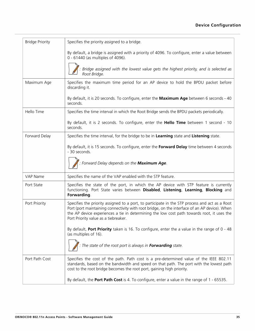
Bridge Priority Specifies the priority assigned to a bridge.
By default, a bridge is assigned with a priority of 4096. To configure, enter a value between0 - 61440 (as multiples of 4096).
: Bridge assigned with the lowest value gets the highest priority, and is selected asRoot Bridge.
Maximum Age Specifies the maximum time period for an AP device to hold the BPDU packet beforediscarding it.
By default, it is 20 seconds. To configure, enter the Maximum Age between 6 seconds - 40seconds.
Hello Time Specifies the time interval in which the Root Bridge sends the BPDU packets periodically.
By default, it is 2 seconds. To configure, enter the Hello Time between 1 second - 10seconds.
Forward Delay Specifies the time interval, for the bridge to be in Learning state and Listening state.
By default, it is 15 seconds. To configure, enter the Forward Delay time between 4 seconds- 30 seconds.
: Forward Delay depends on the Maximum Age.
VAP Name Specifies the name of the VAP enabled with the STP feature.
Port State Specifies the state of the port, in which the AP device with STP feature is currentlyfunctioning. Port State varies between Disabled, Listening, Learning, Blocking andForwarding.
Port Priority Specifies the priority assigned to a port, to participate in the STP process and act as a RootPort (port maintaining connectivity with root bridge, on the interface of an AP device). Whenthe AP device experiences a tie in determining the low cost path towards root, it uses thePort Priority value as a tiebreaker.
By default, Port Priority taken is 16. To configure, enter the a value in the range of 0 - 48(as multiples of 16).
: The state of the root port is always in Forwarding state.
Port Path Cost Specifies the cost of the path. Path cost is a pre-determined value of the IEEE 802.11standards, based on the bandwidth and speed on that path. The port with the lowest pathcost to the root bridge becomes the root port, gaining high priority.
By default, the Port Path Cost is 4. To configure, enter a value in the range of 1 - 65535.
ORiNOCO® 802.11n Access Points - Software Management Guide 35
Device Configuration
Click OK and COMMIT, to save the configured parameters.
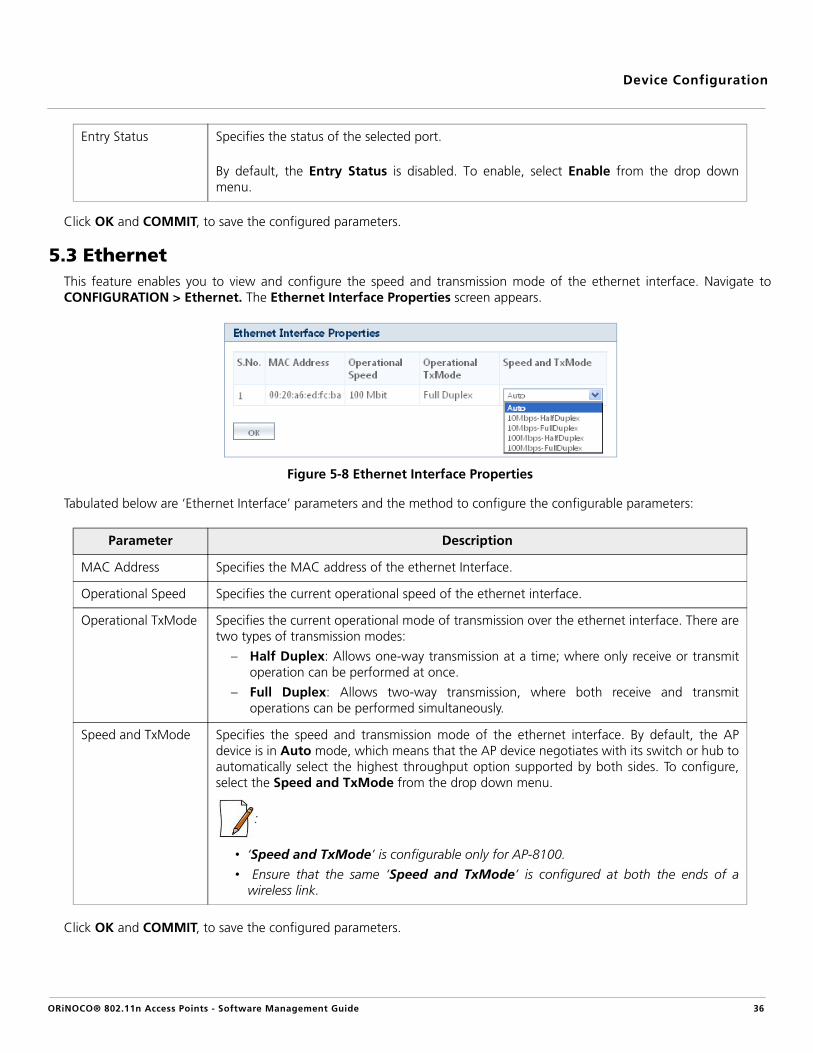
5.3 EthernetThis feature enables you to view and configure the speed and transmission mode of the ethernet interface. Navigate toCONFIGURATION > Ethernet. The Ethernet Interface Properties screen appears.
Figure 5-8 Ethernet Interface Properties
Tabulated below are ‘Ethernet Interface’ parameters and the method to configure the configurable parameters:
Click OK and COMMIT, to save the configured parameters.
Entry Status Specifies the status of the selected port.
By default, the Entry Status is disabled. To enable, select Enable from the drop downmenu.
Parameter Description
MAC Address Specifies the MAC address of the ethernet Interface.
Operational Speed Specifies the current operational speed of the ethernet interface.
Operational TxMode Specifies the current operational mode of transmission over the ethernet interface. There aretwo types of transmission modes:
– Half Duplex: Allows one-way transmission at a time; where only receive or transmitoperation can be performed at once.
– Full Duplex: Allows two-way transmission, where both receive and transmitoperations can be performed simultaneously.
Speed and TxMode Specifies the speed and transmission mode of the ethernet interface. By default, the APdevice is in Auto mode, which means that the AP device negotiates with its switch or hub toautomatically select the highest throughput option supported by both sides. To configure,select the Speed and TxMode from the drop down menu.
:
• ‘Speed and TxMode’ is configurable only for AP-8100.
• Ensure that the same ‘Speed and TxMode’ is configured at both the ends of awireless link.
ORiNOCO® 802.11n Access Points - Software Management Guide 36
Device Configuration
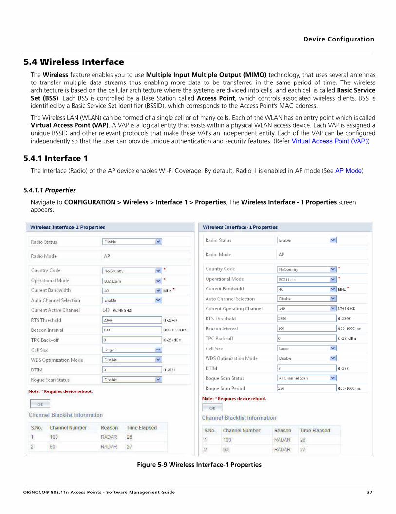
5.4 Wireless InterfaceThe Wireless feature enables you to use Multiple Input Multiple Output (MIMO) technology, that uses several antennasto transfer multiple data streams thus enabling more data to be transferred in the same period of time. The wirelessarchitecture is based on the cellular architecture where the systems are divided into cells, and each cell is called Basic ServiceSet (BSS). Each BSS is controlled by a Base Station called Access Point, which controls associated wireless clients. BSS isidentified by a Basic Service Set Identifier (BSSID), which corresponds to the Access Point’s MAC address.
The Wireless LAN (WLAN) can be formed of a single cell or of many cells. Each of the WLAN has an entry point which is calledVirtual Access Point (VAP). A VAP is a logical entity that exists within a physical WLAN access device. Each VAP is assigned aunique BSSID and other relevant protocols that make these VAPs an independent entity. Each of the VAP can be configuredindependently so that the user can provide unique authentication and security features. (Refer Virtual Access Point (VAP))
5.4.1 Interface 1
The Interface (Radio) of the AP device enables Wi-Fi Coverage. By default, Radio 1 is enabled in AP mode (See AP Mode)
5.4.1.1 Properties
Navigate to CONFIGURATION > Wireless > Interface 1 > Properties. The Wireless Interface - 1 Properties screen appears.
Figure 5-9 Wireless Interface-1 Properties
ORiNOCO® 802.11n Access Points - Software Management Guide 37

Device Configuration
Tabulated below are ‘Wireless Interface’ parameters and the method to configure the configurable parameters:
Parameter Description
Radio Status Specifies the status of the radio on the AP device.
By default, it is enabled. To disable, select Disable from the drop down menu. If the radiostatus is disabled, the interface gets shutdown.
Radio Mode This parameter enables you to set the radio mode of the AP device. The available radio modeis AP.
Country Code Specifies the country where the AP device is used. To configure this parameter, select acountry from the drop down menu.
:
• Country selection is available only on AP devices with model numbers ending in -WD.Setting the Country Code, makes the AP Device automatically compliant with therules of the regulatory domain in which it is used, by configuring the allowed frequencybands, channels, Dynamic Frequency Selection, Transmit Power Control and powerlevels.
• If the country is not selected, an informational message will appear on the Status page,and you will be unable to configure interface parameters. The regulatory domain ispre-programmed into the AP devices in which country selection is not available on thesystem tab, prior to its shipment.
Operational Mode Specifies the mode of communication between the AP device and the wireless client(s).
However, you can also configure the operational mode as either 802.11a, 802.11g or802.11g/n, for Interface 1 of AP-800 / AP-8000.
:
• The Interface (Radio) 1 can be configured only in 5 GHz frequency band (802.11a or802.11a/n modes), for the AP-8000-JP (Japan SKU).
• The Interface (Radio) 1 can be configured only in 5 GHz and Interface (Radio) 2 can beconfigured only in 2.4 GHz frequency band, for AP-8100-WD/JP/US.
• Configuring the Current Bandwidth to 20 MHz sets back the operational mode tofactory default value. Hence, ensure that you re-configure the operational mode andcommit the changes.
By default, the operational modes supported on both the radios is tabulated below.
Device Type
Operational Mode
Radio 1 Radio 2
AP-800 802.11g/n Not Applicable
AP-8000 802.11a/n 802.11g/n
AP-8100 802.11a/n 802.11g/n
ORiNOCO® 802.11n Access Points - Software Management Guide 38

Device Configuration
Current Bandwidth Specifies the frequency band used to transmit the wireless data. The available bandwidthsare 20 MHz and 40 MHz.
By default, the AP device operates in 40MHz. To set the bandwidth for the wireless datatransmission, select a value from the drop down menu.
: Set the current bandwidth to 20 MHz, to enable the legacy operational modes of802.11a or 802.11g.
Auto Channel Selection
This parameter enables the AP device to determine the best channel for wireless datatransmission with less interference. When this parameter is enabled in AP Mode, the APdevice scans all the available channels and selects the best channel to establish a connection.
By default, Auto Channel Selection is disabled. To enable, select Enable from the dropdown menu.
: When the AP device detects RADAR on the current operating channel, the AutoChannel Selection gets enabled automatically though user disables it.
Current Active Channel
When the Auto Channel Selection is enabled, this parameter displays the current activechannel on the wireless interface.
Current Operating Channel
This parameter is applicable only when the Auto Channel Selection is disabled and theRadio Mode is set to AP. This parameter enables the user to select the current operatingchannel for the wireless interface.
To configure this parameter, select current operating channel for the wireless interface fromthe Current Operating Channel drop down menu. Note that, when you select thechannel, its corresponding frequency is displayed on the right-side of the drop down box.
RTS Threshold Specifies the RTS (Request-to-Send) threshold value. If the size of the MPDU is of thespecified threshold value or greater than that, the AP device then uses the RTS mechanismfor data transmission.
By default, it is 2346, where RTS is disabled. To configure, enter a value ranging from 1 to2346 in the RTS Threshold box.
Beacon Interval Specifies the interval between two successive beacons. By default, the value is set to 100ms.To configure, enter a value ranging from 100 to 1000ms in the Beacon Interval box.
:
• The AP device operates with a channel bandwidth of 20 MHz (Dynamic20/40 Mode) only, when the extension channel is busy and currentbandwidth is set to 40 MHz. This avoids unnecessary retries at a higherrate.
• Once, the extension channel is available, the device will switch back to thechannel bandwidth of 40 MHz. See WDS Optimization Mode for details, if aVAP is enabled in WDS mode.
ORiNOCO® 802.11n Access Points - Software Management Guide 39

Device Configuration
TPC (Transmit Power Control) Back-off
The AP device transmits maximum output power, as per the selected frequency and country(regulatory domain). With TPC Back-off, you can adjust the output power of the AP device toa lower level in order to reduce the interference with the neighboring devices or to use ahigher gain antenna without violating the maximum radiated output power allowed for yourregulatory domain.
By default, it is set to 0 dBm. To configure, enter a value ranging from 0 to 25 dBm in theTPC Back-off box.
: TPC Back-off range (0-25 dBm) varies for different cell sizes (Large, Medium, Small,Micro and Mini).
Cell Size Specifies the parameter that enables you to control the coverage area of the AP device indifferent types of deployment scenarios. For instance, usage of small cell size in dense devicedeployment, minimizes the interference caused by one device on another.
Cell Sizes supported by the AP device are Large, Medium, Small, Micro and Mini. By default,it is Large. To configure, select the Cell Size from the drop down menu.
Cell Size Functionality
It is classified for different VAP types (See Virtual Access Point (VAP), for details),defining the relation between transmit power, receive sensitivity and CCA thresholdassociated with different Cell Sizes.
Type Description
AP Cell Size Functionality When the cell size is set to Large, the transmit power andreceive sensitivity are high. When the Cell Size is set fromLarge to Micro, Mini, Small or Medium, the transmit poweris reduced.
Tabulated below are the details that explain the AP Cell SizeFunctionality for different Cell Sizes.
* Maximum Transmit Power depends on the selected Fre-quency Domain and the type of radio Card.
Cell Size Maximum Tx Power* (dBm)
Receive Sensitivity Threshold
(dBm)
Clear Channel Assessment
Threshold (dBm)
Large MaximumTxPower
-96 -62
Medium MaximumTxPower-3
-86 -62
Small MaximumTxPower-6
-78 -52
Micro MaximumTxPower-9
-70 -42
Mini MaximumTxPower-12
-62 -36
ORiNOCO® 802.11n Access Points - Software Management Guide 40

Device Configuration
Cell Size
:
• To balance the transmit Power and receive sensitivity at both the ends (END-A andEND-B), WDS Optimization Mode should be enabled for a WDS link.
• If the user wants to have AP cell size functionality applied, irrespective of the VAPtype, then the TPC value can be increased by using the TPCBackoff parameter.
WDS Optimization Mode
Specifies the optimization mode of a WDS link (See WDS (Wireless Distribution System)Mode), which enables the user to balance the transmit power at both the ends, END-A andEND-B.
To configure, select Enable or Disable from the drop down menu.
:
• If WDS optimization mode is enabled, the WDS Cell Size Functionality is applied.(See WDS Cell Size Functionality)
• If WDS optimization mode is disabled, the AP Cell Size Functionality is applied. (SeeAP Cell Size Functionality)
• When WDS Optimization Mode is enabled, WDS Cell Size Functionality is applied evenon the VAP enabled in AP mode.
WDS Cell Size Functionality
For a WDS link (See WDS (Wireless Distribution System)Mode), when the cell size is set from Large to Micro, Mini,Small or Medium, the transmit power is retained to themaximum value.
Tabulated below are the details that explain the WDS CellSize Functionality for different Cell Sizes.
* Maximum Transmit Power depends on the selected Fre-quency Domain and the type of radio Card.
Cell Size Maximum Tx Power* (dBm)
Receive Sensitivity Threshold
(dBm)
Clear Channel Assessment
Threshold (dBm)
Large MaximumTxPower
-96 -62
Medium MaximumTxPower
-86 -62
Small MaximumTxPower
-78 -52
Micro MaximumTxPower
-70 -42
Mini MaximumTxPower
-62 -36
ORiNOCO® 802.11n Access Points - Software Management Guide 41

Device Configuration
WDS Optimization Mode
DTIM (Delivery Traffic Indication Map)
Specifies the number of beacon frames that can be transmitted before another DTIM istransmitted. An increase in the DTIM period count, allows clients to sleep longer. However, itdelays the delivery of multicast and unicast packets.
By default, it is 3. To configure, enter a value ranging from 1 to 255 in the DTIM box.
: Long DTIM intervals will allow the mobile wireless clients to sleep for longer hoursthus maximizing the battery life. With short DTIM intervals, frequent frame deliverytakes place thus reducing the power save efficiency of the battery.
Rogue Scan Status Specifies the status of the Rogue Scan feature on the AP device. Rogue Scan allows you toscan and monitor all the wireless devices (AP/STA/WDS/ADHOC) and rogue AP devices withinits vicinity and provides statistics of the interference caused by those devices.
Rogue Scanning is done via two modes:
a. Current Channel Scan: In this mode, the AP device scans all the wireless devicesand rogue AP devices in the current operating channel, simultaneously performingthe standard AP functionality.
• AP device listens to all the data packets transmitted over the currentoperating channel, interprets the beacons and probe responses from theneighboring devices and maintains its BSS throughput performance.
• A maximum of 32 wireless devices can be scanned. Once it exceeds thelimit of 32 entries, it overwrites the oldest entry.
b. All Channel Scan: In this mode, the AP device continuously scans all the availablechannels (both active and passive, depending on the channel flags) within itsvicinity. A maximum of 512 wireless devices can be scanned.
By default, Rogue Scan Status is disabled. To enable select either Current Channel Scanor All channel Scan from the drop down menu.
:
• When Auto Channel Selection is enabled, Rogue Scan Status cannot be set to AllChannel Scan.
• In All Channel Scan mode, the AP device does not support the AP functionalitycompletely.
: If,
a. WDS Optimization Mode is enabled,
b. Current Bandwidth is set to 40 MHz and
c. The extension channel is busy
then, the AP device operates with a channel bandwidth of 40 Mhz only(Dynamic 20/40 mode is not applicable here). The same is applicable onthe other VAPs enabled in AP mode.
ORiNOCO® 802.11n Access Points - Software Management Guide 42

Device Configuration
Click OK and COMMIT, to save the configured parameters.
: If you have changed any of the parameters with an asterisk symbol marked against it, then reboot the AP device.
Channel Blacklist Information
A channel is blacklisted when a radar is detected in it. The Channel Blacklist Information table lists all the blacklisted channels,which includes the information tabulated below:
5.4.1.2 11n Properties
Navigate to CONFIGURATION > Wireless > Interface 1 > 11n Properties. The Wireless Interface-1 11n Propertiesscreen appears.
Figure 5-10 Wireless Interface-1 11n Properties
Tabulated below are the ‘11n Properties’ and the method to configure the configurable parameters:
Rogue Scan Period This parameter is enabled when Rogue Scan Status is set to All channel Scan. Thisparameter specifies the time period for which, the AP device scans each available channel todetect every wireless device in its vicinity.
By default, it is 250ms. To configure, enter the time period value between 100- 1000ms
Parameter Description
Channel Number Specifies the channel number of the blacklisted channel.
Reason Specifies the reason for blacklisting a channel.
Time Elapsed Specifies the time period, during which a channel is not operational.
Parameter Description
11n AMPDU (Aggregated MAC Protocol Data Unit)
This parameter enables the user to aggregate several MAC frames into a single large frameto achieve high throughput.
By default, AMPDU status is enabled. To disable, select Disable from the drop down menu.
ORiNOCO® 802.11n Access Points - Software Management Guide 43
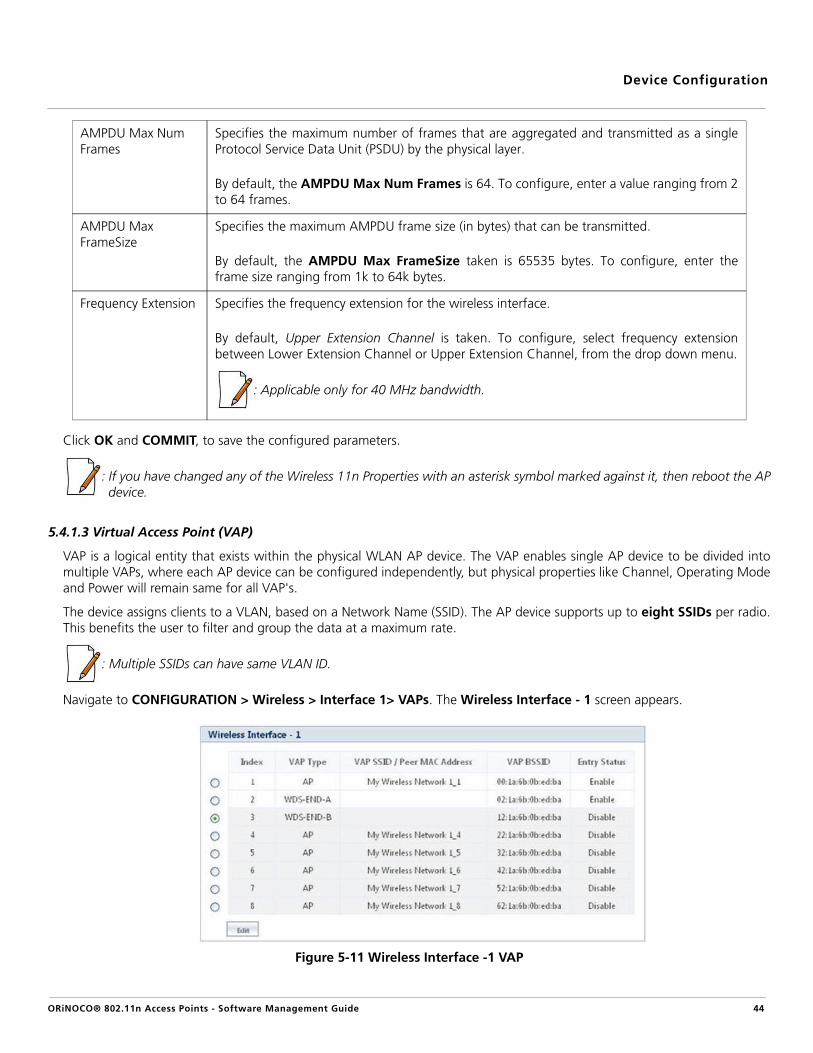
Device Configuration
Click OK and COMMIT, to save the configured parameters.
: If you have changed any of the Wireless 11n Properties with an asterisk symbol marked against it, then reboot the APdevice.
5.4.1.3 Virtual Access Point (VAP)
VAP is a logical entity that exists within the physical WLAN AP device. The VAP enables single AP device to be divided intomultiple VAPs, where each AP device can be configured independently, but physical properties like Channel, Operating Modeand Power will remain same for all VAP's.
The device assigns clients to a VLAN, based on a Network Name (SSID). The AP device supports up to eight SSIDs per radio.This benefits the user to filter and group the data at a maximum rate.
: Multiple SSIDs can have same VLAN ID.
Navigate to CONFIGURATION > Wireless > Interface 1> VAPs. The Wireless Interface - 1 screen appears.
Figure 5-11 Wireless Interface -1 VAP
AMPDU Max Num Frames
Specifies the maximum number of frames that are aggregated and transmitted as a singleProtocol Service Data Unit (PSDU) by the physical layer.
By default, the AMPDU Max Num Frames is 64. To configure, enter a value ranging from 2to 64 frames.
AMPDU Max FrameSize
Specifies the maximum AMPDU frame size (in bytes) that can be transmitted.
By default, the AMPDU Max FrameSize taken is 65535 bytes. To configure, enter theframe size ranging from 1k to 64k bytes.
Frequency Extension Specifies the frequency extension for the wireless interface.
By default, Upper Extension Channel is taken. To configure, select frequency extensionbetween Lower Extension Channel or Upper Extension Channel, from the drop down menu.
: Applicable only for 40 MHz bandwidth.
ORiNOCO® 802.11n Access Points - Software Management Guide 44

Device Configuration
Each wireless interface supports eight VAPs. By default, the first VAP on an interface is always enabled. The AP devicesupports two VAP types:
A. AP (Access Point) Mode
B. WDS (Wireless Distribution System) Mode
A. AP Mode
The VAP enabled in AP mode will support the standard AP functionality.
To configure a VAP in AP mode, select the radio button against the desired VAP and click Edit (See Wireless Interface -1VAP). The configuration screen to edit the properties of selected VAP appears:
Figure 5-12 Wireless Interface 1 / VAP in AP Mode - Edit Properties
Tabulated below are ‘AP Mode’ parameters and the method to configure the configurable parameters:
Parameter Description
Status Specifies the status of the VAP.
By default, the first VAP is always enabled and other VAPs are disabled. To enable a VAP,select Enable from the drop down menu.
Type Specifies the VAP Type.
By default, the VAP Type is AP. Configurable VAP types are AP, WDS-END A, WDS-END B,WDS-Legacy. (See Wireless Distribution System (WDS) for details)
ORiNOCO® 802.11n Access Points - Software Management Guide 45

Device Configuration
SSID Specifies the unique network name used to identify a wireless network. To change thewireless network name, enter a new name in the SSID box with a maximum of 31characters.
BSSID Specifies a read-only parameter and it displays the VAP’s MAC Address.
Broadcast SSID The continuous announcement of the SSID in the beacons by VAP is called Broadcast SSID.The SSID is also broadcasted in probe response frames.
For a VAP to broadcast SSID in beacons, select Enable from the Broadcast SSID box. Whendisabled, clients which are not aware of the SSID cannot connect to the AP device.
Multicast Rate Specifies the rate at which the multicast data packets are transmitted over the wirelessnetwork.
By default, the Multicast Rate taken is 9 Mbps for operational modes 11na/a and it is 11Mbps for operational modes 11ng/g. To configure, select the rate of data transmission fromthe drop down menu.
:
• The configured multicast rate value rolls back to its default value when the operationalmode of the AP device changes.
• While configuring multicast rate, please ensure that all the clients in the network cancommunicate with the configured rate.
Fragmentation Threshold
The process of dividing a MAC Service Data Unit (MSDU) into smaller MAC level frames fortransmission over the wireless network is called Fragmentation.This reduces both theprobability and adverse effects of wireless packet corruption, improving the overall wirelessnetwork performance.
Unicast receiver address can be fragmented, whereas Broadcast/Multicast frames cannot befragmented, even though they exceed a fragmentation threshold. If the size of the datapacket is more than the configured value, AP Device breaks the data into pieces calledFragments and transmits. Each fragment size is the Fragmentation Threshold.
By default, it is set to 2346 bytes. To configure, enter a value ranging from 256 to 2346bytes in the Fragmentation Threshold box.
: ‘Fragmentation Threshold’ is not configurable in 11n mode.
Security Profile Name
Specifies the name of the Security profile for the wireless VAP.
By default, the available Security Profile Name is “AP Security”. To configure, click theSecurity Profile Name box and select the security profile. (Refer Wireless Security)
RADIUS Profile Name
Specifies the name of the RADIUS profile for the wireless VAP.
By default, the available RADIUS Profile name is “Default RADIUS”. Refer RADIUS
ORiNOCO® 802.11n Access Points - Software Management Guide 46

Device Configuration
VLAN ID Specifies the VLAN ID for the wireless VAP.
By default, the VLAN ID is set to -1 which means that VLAN tag is disabled. To enable VLANtag, enter a value ranging from 1 to 4094 in the VLAN ID box.
VLAN Priority Specifies the VLAN priority for the Wireless VAP.
By default the value is set to 0. To configure this parameter, enter a value ranging from 0 to7 in the VLAN Priority box.
: To configure the VLAN ID and VLAN Priority for a VAP, VLAN status should beenabled. (See Virtual Local Area Network (VLAN))
QoS Profile Name Specifies the QoS profile name for the Wireless VAP. You can configure the QoS Profilename as either Default or NONE.
By Default, it is “Default”. To configure, enter the QoS profile name in the QoS ProfileName box. See QoS Profile.
:
• If the QoS Profile Name is defined as NONE, then by default the QoS feature will bedisabled.
• By default, QoS Profile Name is taken as NONE for legacy mode. It can be manuallyenabled by changing it to Default QoS Profile.
Local MAC Authentication
This parameter is used to either enable or disable the local MAC Access Control list. ClickLocal MAC Authentication box to either enable or disable its status.
RADIUS MAC Authentication
This parameter is used to either enable or disable the MAC Access Control for RADIUSProfiles. Click the RADIUS MAC Authentication box to either enable or disable its status.
: If you have enabled Local MAC Authentication, then do not enable RADIUS MACAuthentication.
RADIUS Accounting This parameter is used to either enable or disable the RADIUS Accounting Status. Click theRADIUS Accounting box to either enable or disable its status.
: To enable RADIUS Accounting on a VAP, the RADIUS Accounting Server Statusshould be enabled.
ORiNOCO® 802.11n Access Points - Software Management Guide 47

Device Configuration
Click OK and COMMIT, to save the configured parameters.
:
• To configure VLAN on the AP device, the global VLAN status should be enabled.
• ‘Fragmentation Threshold’ and ‘Multicast Rate’, roll back to their default values when the Operational Mode ofthe radio is changed.
• We recommend you to connect the AP Device to a maximum of 35 to 40 clients simultaneously, for a better performance and higher throughputs.
B. Wireless Distribution System (WDS)
A Wireless Distribution System (WDS) helps you to establish a wireless link between two BSS and allows the clients of oneBSS network to communicate with the clients of other BSS network. WDS helps in extending the WLAN, where it is difficult touse the wired ethernet to relay the packets between the networks.
Following figure and example illustrate the work process of WDS:
Max Stations This parameter allows you to restrict the maximum number of wireless clients that can beassociated with each VAP. A maximum of 128 wireless clients can be connected per radio.
By default, the Max Stations value taken for each VAP is 64. To configure, enter a valueranging from 1 to 128.
: A VAP (already connected to the maximum number of wireless clients) responds to aprobe request from a new client, with a probe response. But it responds to theauthentication request, with a proper error code, specifying the Max Stations limit.
Number of Clients per Radio
If ‘n’ is the number of VAPs enabled on a radio, then tabulated below are the number of clients supported per radio, in security mode.
* Maximum number of clients per Radio.* The maximum of clients supported per VAP in an open authentication mode is 127.
Security Mode Maximum Number of Clients*
Example: If no. of VAP(s) ‘n=1’, then Maximum Number of Clients*
WEP 127 127
PSK + TKIP (62 - n) (62 - 1) = 61
PSK + AES (124 - n) (124 - 1) = 123
PSK + TKIP + AES (62 - n) (62 - n) = 61
Dot1x + WEP (124 - n) (124 - 1) = 123
Dot1x + TKIP (62 - n) (62 - 1) = 61
Dot1x + AES (124 - n) (124 - 1) = 123
Dot1x + TKIP + AES (62 - n) (62 - n) = 61
ORiNOCO® 802.11n Access Points - Software Management Guide 48

Device Configuration
Figure 5-13 Wireless Distribution System
Lets say, Access Point 1 of BSS1 wants to communicate with Access Point 2 of the BSS2 in its vicinity. In such a scenario, boththe Access Points 1 and 2, register each other's MAC address. Once registered, a WDS link is established between BSS 1 andBSS 2. The data transmission over the WDS link follows a four address format, which contains 1) MAC address of the source,2) MAC Address of the destination, 3) MAC Address of the transmitting AP device, 4) MAC Address of the receiving APdevice.
WDS supports two modes:
1. WDS - Legacy Mode: In this mode, a WDS link can be established between two Legacy AP devices supporting the IEEE 802.11 a/b/g modes, without serving the 11n authentication functionality while establishing the WDS link. This mode supports the WEP encryption type to secure the data.
By using this mode we can connect AP-800 / AP-8000 / AP-8100 with legacy products AP-700 / AP-4000. To establisha WDS link in this mode, configure both the VAPs in WDS-Legacy mode. To configure VAP in this mode, you need toconfigure the following parameters first:
— Operational Mode: Set Operational Mode to 802 11a / 11g. Refer Properties— Current Bandwidth: Set Current Bandwidth to 20 MHz. Refer Properties
Now, you can select the VAP Type as WDS-Legacy.
2. WDS - 11n Mode: In this mode, a WDS link can be established between two BSS supporting the IEEE 802.11n a/ng modes, serving the association and authentication functionalities. This mode supports the AES (128 bit) encryption type to secure the data. In WDS-11n mode, each VAP can be configured as either:
a. WDS END - A: The VAP enabled in this mode will act as a WDS enabled AP device and performs standard AP functionality.
b. WDS END - B: The VAP enabled in this mode will act as a WDS enabled wireless client and perform the functions of a station/client.
By using this mode, we can connect only to AP-800 / AP-8000 / AP-8100. To establish a WDS link in this mode, oneVAP should be set to “WDS-END-A” and other VAP should be set to “WDS-END-B”. To configure VAP in this mode,you need to configure the following parameters first:
— Operational Mode: Set Operational Mode to 802 11a/n or 11g/n. Refer Properties— Current Bandwidth: Set Current Bandwidth to 20 MHz or 40 MHz. Refer Properties
Now, you can select the VAP-Type as WDS-END A or WDS-END B.
Navigate to Configuration > Wireless > Interface 1 / Interface 2 > VAP, the configuration screens (WDS-legacy orWDS-11n, as selected) appear:
ORiNOCO® 802.11n Access Points - Software Management Guide 49

Device Configuration
Tabulated below are the ‘WDS Mode’ parameters and the method to configure the configurable parameters:
Parameter Description
Status Specifies the status of the VAP.
By default, it is enabled. To disable a VAP, select Disable from the drop down menu.
Type Specifies the type of the VAP configured. (VAP Type may be in AP, WDS-Legacy or WDSEND-A/END-B). See WDS - Legacy Mode and WDS-11n Mode
Select the VAP Type from the drop down menu and click OK.
: The AP device performs the standard AP functionality, if the VAP type is selected toAP mode (See AP Mode).
BSSID Specifies a read-only parameter which displays the VAP MAC address.
Peer MAC Address Specifies the MAC Address of the destination VAP. Enter a valid MAC Address in the PeerMAC Address box.
Security Profile Name
Specifies the Security profile name for the wireless VAP.
By default, it is “AP Security”. To configure, select the security profile from the drop downmenu.
QoS Profile Name Specifies the QoS profile name for the Wireless VAP. By default, the QoS Profile Name is setto “Default”. (See QoS Profile).
: By default, the QOS profile name is set to NONE, for legacy mode. It can be manuallyenabled to Default QoS Profile.
Figure 5-14 (a) VAP in WDS - Legacy Mode Figure 5-14 4 (b) VAP in WDS - 11n Mode
ORiNOCO® 802.11n Access Points - Software Management Guide 50

Device Configuration
Click OK and COMMIT, to save the configured changes.
:
• All the eight VAPs on an interface, can be enabled in WDS mode.
• WDS does not support the Dynamic Frequency Selection (DFS).
• The nodes participating in establishment of a WDS link on either sides, should be configured with same channel andsecurity settings.
5.4.2 Interface 2
The Interface (Radio) 2 on the AP device enables Wi-Fi Coverage. To configure wireless interface 2 properties, follow the sameprocedure as explained in Interface 1.
By default, the Operational Mode for Interface 2 (Radio2) is set to 802.11g/n. However, you can also configure theoperational mode for Interface 2 in either 802.11a, 802.11g or 802.11g/n modes.
: The Interface (Radio) 2 can be configured only in 2.4 GHz frequency band (i.e in 802.11g or 802.11g/n modes), for:
• The JP (Japan) SKU of AP-8000
• All the SKUs (WD, JP, US) of AP-8100.
All the configuration properties for interface 2 (Radio 2) are same as interface (Radio) 1 properties. To configure the propertiesand 11n properties on interface 2, refer Properties and 11n Properties, respectively. To configure the VAPs on interface 2,refer Virtual Access Point (VAP).
:
• By default, the Operational Mode for interface (radio) 2 is set to 802.11g/n.
• Interface 2 configuration is applicable only to a dual-radio device.
5.5 SecurityThe AP device supports the following enhanced security features, that enable you to prevent unauthorized access or damageto the nodes on the wireless networks.
• Wired Equivalent Privacy (WEP) Encryption
WEP provide confidentiality for network traffic by using the wireless protocol. WEP encrypts the data portion of eachpacket exchanged on an 802.11 network by using an Encryption Key (also known as a WEP Key). When Encryption isenabled, two 802.11 AP devices must have the same Encryption Keys and both devices must be configured to useEncryption in order to communicate.
: When WDS link is DOWN, the following behavior is expected:
• If WDS-ENDA and VAP-AP are on same radio, then the VAP-AP transmits the beacons.
• All the VAPs on the same interface (radio) as WDS-END B, stop transmitting the beacons.
• The VAPs on an interface (radio) other than WDS-END B, transmit the beacons.
ORiNOCO® 802.11n Access Points - Software Management Guide 51

Device Configuration
• 802.1x Authentication
802.1x provides an authentication framework for wireless LANs, allowing a user to be authenticated by a centralauthority. 802.1x uses an existing protocol, the Extensible Authentication Protocol (EAP, RFC 2284), that works onEthernet, Token Ring, or wireless LANs for message exchange during the authentication process.
In a wireless LAN with 802.1x, a user (known as the Supplicant) requests access to an Access Point (known as theAuthenticator). The Access Point forces the user into an unauthorized state that allows the client to send only an EAPstart message. The Access Point returns an EAP message requesting the user's identity. The client returns the identity,which is then forwarded by the Access Point to the authentication server (Remote Authentication Dial-In User Service(RADIUS)), which uses an algorithm to authenticate the user and then returns an accept or reject message back to theAccess Point. Assuming an accept was received, the Access Point changes the client's state to authorized and normaltraffic can now flow.
• Wi-Fi Protected Access (WPA/802.11i [WPA2])
— WPA: WPA is a replacement for WEP. WPA uses the Temporal Key Integrity Protocol (TKIP) for keymanagement, and offers a choice of either the 802.1x authentication framework together with extensibleauthentication protocol (EAP) for enterprise WLAN security (Enterprise mode), or simpler pre-shared key (PSK)authentication for the home or small office network which does not have an authentication server (Personalmode).
— WPA2: IEEE 802.11i, also known as WPA2, is an amendment to the 802.11 standard specifying securitymechanisms for wireless networks. 802.11i uses Advanced Encryption Standard (AES) block cipher.
5.5.1 Wireless Security
Navigate to CONFIGURATION > Security > Wireless Security. The Wireless Security Configuration screen appears.
Figure 5-15 Wireless Security Configuration
Tabulated below are the ‘Wireless Security’ parameters and the method to configure the configurable parameters:
Click OK and COMMIT, to save the configured parameters.
Parameter Description
Profile Name Specifies the user-defined name for a security profile.
Auth Mode Specifies the security mode for the wireless network. The Auth Mode may vary betweenNone, WEP, PSK, 802.1x. (See Create a New Security Profile.)
Entry Status Specifies the status of the user-defined security profiles. The available status are:
– Enable: Enables the user-defined Security profile.
– Disable: Disables the user-defined Security profile.
– Delete: Deletes the user-defined Security profile.
ORiNOCO® 802.11n Access Points - Software Management Guide 52

Device Configuration
5.5.1.1 Create a New Security Profile
To add a new security profile, click Add in the Wireless Security Configuration screen. The Wireless Security Add Rowscreen appears.
Figure 5-16 Add Wireless Security Profile
Tabulated below are the ‘Wireless Security Profile’ parameters and the method to configure the configurable parameters:
Parameter Description
Profile Name Specifies the name of the Security Profile that is being created. To configure, enter thedesired Profile Name.
Authentication Mode
Specifies the security mode for the wireless network. Select any of the followingauthentication modes for the wireless interface from the drop down menu:
a. None: If you select this Authentication Mode, then no security exists on the wirelessnetwork.
b. WEP (Wired Equivalent Privacy): Select WEP from the Authentication mode dropdown menu and the configuration screen appears:
Figure 5-17 WEP Authentication Mode
Configure the following parameters in WEP Authentication Mode:
ORiNOCO® 802.11n Access Points - Software Management Guide 53

Device Configuration
Authentication Mode
: Enable only one security profile of WEP Authentication mode at once, when multipleVAPs are enabled.
c. PSK (Pre-Shared Key): Select PSK from the Authentication mode drop down menuand the configuration screen appears:
Figure 5-18 PSK Authentication Mode
Configure the following parameters in PSK Authentication Mode:
Parameter Description
Key This parameter allows you to configure the WEP key forthe wireless security. Enter a WEP Key in the Key box.
– For 64-bit encryption, an encryption key is 10hexadecimal characters (0-9 and A-F) or 5 ASCIIcharacters. See ASCII Character Chart.
– For 128-bit encryption, an encryption key is 26hexadecimal characters or 13 ASCII characters.
– For 152-bit encryption, an encryption key is 32hexadecimal characters or 16 ASCII characters.
: Special characters like - = \ " '? / space are notallowed while configuring the WEP key.
ORiNOCO® 802.11n Access Points - Software Management Guide 54

Device Configuration
Authentication Mode
d. 802.1x: Select 802.1x (Dot1x) from the Authentication mode drop down menu andthe configuration screen appears:
Figure 5-19 802.1x Authentication Mode
Configure the following parameters in 802.1x (Dot1x) Authentication Mode:
Parameter Description
Encryption Type Specifies the Encryption Type.
By default, it is taken as WPA-TKIP. To configure, selecteither WPA-TKIP, WPA2-AES or WPA-WPA2AES-TKIPfrom the drop down menu.
:When the Encryption Type is set toWPA-WPA2AES-TKIP, the device supports clientswith the encryption type of either WPA-TKIP orWPA2-AES.
PSK Specifies the pass phrase that derives the PSK. Toconfigure, enter a security key ranging from 8 to 63characters in the PSK box.
: Special characters like - = \ " '? / space are notallowed while configuring the pass phrase.
Rekeying Interval Specifies the interval at which the device will send groupkeys to all the associated clients.
By default the Rekeying Interval value is set to 43200.To configure, enter a value ranging from 900 to 65535seconds.
ORiNOCO® 802.11n Access Points - Software Management Guide 55

Device Configuration
Click Add, to save the new profile with configured parameters.
:
• You can add or edit a maximum of 16 security profiles.
• In case of a WDS link, supported security keys are:
– For WEP Encryption, key length should be (ASCII 5/13/16) (Hex 10/26/32)
– For AES or TKIP encryption, key length should be 16 ASCII characters or 32 Hex digits.
– For 11na/11ng modes, WEP/TKIP Encryption will work only in Legacy (11 a/b/g) data rates.
• If the PSK and WEP key passwords are not configured, then the AP device uses the following default passwords:
– WEP : 1234567890
– PSK: 1234679890123456
• Proxim does not recommend using WEP/TKIP in 11n operational mode.
5.5.1.2 Edit an Existing AP Security Profile
To edit an existing AP security profile, click the Edit icon against the AP security profile that you wish to edit, in theWireless Security Configuration screen. The Wireless Security Edit Row screen appears.
Figure 5-20 AP - Edit Wireless Security Profile
Authentication Mode
Entry Status Specifies the status for the security profile. By default, it is enabled. To configure, select theEntry Status from the drop down menu.
Parameter Description
Encryption Type Specifies the Encryption Type. By default, it is taken asWEP. To configure, enter the Encryption Type as eitherWEP, WPA-TKIP, WPA2-AES or WPA-WPA2AES-TKIP fromthe drop down menu.
:When the Encryption Type is set toWPA-WPA2AES-TKIP, the device supports clientswith the encryption type of either WPA-TKIP orWPA2-AES.
Rekeying Interval Specifies the interval at which the device will send groupkeys to all the associated clients.
By default, the Rekeying Interval value is set to 43200.To configure, enter a value ranging from 900 to 65535seconds.
ORiNOCO® 802.11n Access Points - Software Management Guide 56

Device Configuration
Configure the following parameters:
Click OK and COMMIT, to save the configured parameters.
5.5.2 RADIUS
Remote Authentication Dial In User Service (RADIUS) is a networking protocol that provides centralized Authentication,Authorization, and Accounting (AAA) management for nodes to connect and use a network service.
The AP device supports the following Authentication and Accounting mechanisms:
• MAC Access Control Via RADIUS Authentication: Allows only the MAC addresses that are registered on theRADIUS server to access the wireless network.
• 802.1x Authentication using RADIUS: Refer 802.1x Authentication• RADIUS Accounting: By using an external RADIUS server, the AP device can track and record the length of client
sessions by sending the RADIUS accounting messages per RFC2866. When a wireless client is successfullyauthenticated, RADIUS accounting is initiated by sending an “Accounting Start” request to the RADIUS server. Whenthe wireless client session ends, an “Accounting Stop” request is sent to the RADIUS server.
5.5.2.1 Authentication Attributes
• User-Name: Specifies the name of the user that needs to be authenticated. It must be sent in Access-Request packets,if available.
• User-Password: Specifies the user password to be authenticated, or the user's input following an Access-Challenge.It is only used in Access-Request packets.
• NAS-IP-Address: Specifies the identifying IP Address of the NAS (AP device) which is requesting authentication of theuser, and should be unique to the NAS (AP device) within the scope of the RADIUS server. NAS-IP-Address is only usedin Access-Request packets.
• State: Specifies the attribute sent by the server to the client in an Access-Challenge and must be sent unmodifiedfrom the client to the server in the new Access-Request reply to that challenge, if any.
• Class: Specifies the attribute sent by the server to the client in an Access-Accept and should be sent unmodified by theclient to the accounting server as part of the Accounting-Request packet if accounting is supported.
• Session-Time-out: Specifies the attribute that sets the maximum number of seconds of service to be provided to theuser before termination of the session or prompt. This Attribute is available to be sent by the server to the client in anAccess-Accept or Access-Challenge.
• Termination-Action: Specifies the action taken by the NAS (AP device) when the specified service is completed. It isonly used in Access-Accept packets.
• Called-Station-Id: Specifies the MAC address of the AP device’s wireless interface, with which the client getsauthenticated.
• Calling-Station-Id: Specifies the MAC address of the wireless client being authenticated.
Parameter Description
Profile Name Specifies the name of the Security Profile that is being created. To configure, enter thedesired Profile Name.
Authentication Mode
Specifies the security mode for the wireless network. The Auth Mode may vary betweenNone, WEP, PSK, 802.1x. (See Create a New Security Profile)
Entry Status Specifies the status of the security profile selected.
By default, it is enabled. To configure, select the Entry Status from the drop down menu.
ORiNOCO® 802.11n Access Points - Software Management Guide 57
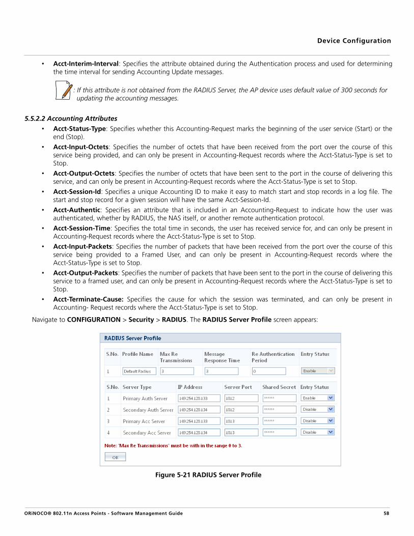
Device Configuration
• Acct-Interim-Interval: Specifies the attribute obtained during the Authentication process and used for determiningthe time interval for sending Accounting Update messages.
: If this attribute is not obtained from the RADIUS Server, the AP device uses default value of 300 seconds for updating the accounting messages.
5.5.2.2 Accounting Attributes
• Acct-Status-Type: Specifies whether this Accounting-Request marks the beginning of the user service (Start) or theend (Stop).
• Acct-Input-Octets: Specifies the number of octets that have been received from the port over the course of thisservice being provided, and can only be present in Accounting-Request records where the Acct-Status-Type is set toStop.
• Acct-Output-Octets: Specifies the number of octets that have been sent to the port in the course of delivering thisservice, and can only be present in Accounting-Request records where the Acct-Status-Type is set to Stop.
• Acct-Session-Id: Specifies a unique Accounting ID to make it easy to match start and stop records in a log file. Thestart and stop record for a given session will have the same Acct-Session-Id.
• Acct-Authentic: Specifies an attribute that is included in an Accounting-Request to indicate how the user wasauthenticated, whether by RADIUS, the NAS itself, or another remote authentication protocol.
• Acct-Session-Time: Specifies the total time in seconds, the user has received service for, and can only be present inAccounting-Request records where the Acct-Status-Type is set to Stop.
• Acct-Input-Packets: Specifies the number of packets that have been received from the port over the course of thisservice being provided to a Framed User, and can only be present in Accounting-Request records where theAcct-Status-Type is set to Stop.
• Acct-Output-Packets: Specifies the number of packets that have been sent to the port in the course of delivering thisservice to a framed user, and can only be present in Accounting-Request records where the Acct-Status-Type is set toStop.
• Acct-Terminate-Cause: Specifies the cause for which the session was terminated, and can only be present inAccounting- Request records where the Acct-Status-Type is set to Stop.
Navigate to CONFIGURATION > Security > RADIUS. The RADIUS Server Profile screen appears:
Figure 5-21 RADIUS Server Profile
ORiNOCO® 802.11n Access Points - Software Management Guide 58

Device Configuration
Tabulated below are the ‘RADIUS Server Profile’ parameters and the method to configure the configurable parameters:
Click OK and COMMIT, to save the configured parameters.
Parameter Description
Profile Name Specifies the RADIUS profile name which is used to identify a set of four RADIUS serversconfigured one per Accounting, Authentication, Secondary Accounting and SecondaryAuthentication.
MaxRe Transmissions
Specifies the maximum number of times an authentication request may be retransmitted.
By default, it is set to 3. To configure, enter the Max ReTransmissions in the range of 0 to 3.
Message Response Time
Specifies the response time in seconds, the AP device should wait for the RADIUS server torespond to a request.
By default, it is set to 3. To configure, enter the Message Response Time between therange 3 to 12 seconds.
Re Authentication Period
Specifies the time period after which the AP device must re-authenticate the client with theRADIUS server.
By default, the Re-authentication Period is set to 0. To configure, enter the value betweenthe range 900 to 65535 seconds.
: If the value is set to “0”, then the re-authentication is disabled. This parameter doesnot apply for clients using RADIUS MAC Authentication.
RADIUS Server Profile Table
Server Type Specifies a read-only parameter which indicates the type of RADIUS Server. Server Typemay vary between Primary Accounting Server, Secondary Accounting Server, PrimaryAuthentication Server and Secondary Authentication Server.
IP Address Specifies the IP address of the RADIUS server configured. To configure, enter the IP Addressin the box.
Server Port Specifies the port number, which the AP device and the server use to communicate witheach other. To configure, enter the Server Port number in the box.
Shared Secret Specifies the password shared by the RADIUS server and the AP device. To configure, enter aShared Secret in the box, with a maximum of 64 characters.
: Special characters like - = \ " '? / space are not allowed while configuring the passphrase.
Entry Status Specifies the status of the RADIUS server.
By default, the first RADIUS Server is enabled. To configure, select Enable or Disable fromthe drop down menu.
ORiNOCO® 802.11n Access Points - Software Management Guide 59

Device Configuration
5.5.3 MAC Access Control
The MAC Access Control feature of AP device allows only the authorized wireless clients to access the network. MACAuthentication is supported only on the wireless interface. Navigate to CONFIGURATION > Security > MAC ACL. The MACAccess Control screen appears.
Figure 5-22 MAC Access Control
Configure the following parameters:
Click OK and COMMIT, to save the configuration.
: To enable MAC Access Control, you should enable Local MAC Authentication in VAP.
5.5.3.1 Add Wireless Clients to MAC Access Control Table
To add a MAC address of a wireless client in the MAC Access Control Table, click Add in the MAC Access Control screen.The MAC ACL Add Row screen appears.
Figure 5-23 MAC ACL Add Row
Parameter Description
Operation Type Specifies the two types of operations, Allow or Deny.
– Allow: Allows only the wireless clients in the MAC Access Control Table to access thewireless network.
– Deny: Does not allow the wireless clients in the MAC Access Control Table to accessthe wireless network.
By default, the Operation Type taken is Deny. To configure, select Allow from the dropdown menu.
ORiNOCO® 802.11n Access Points - Software Management Guide 60

Device Configuration
Configure the following parameters:
Click Add, to add the new wireless client configured.
:
• The maximum number of MAC addresses that you can add is 1024.
• For a single VAP, Local MAC-ACL authentication and RADIUS MAC authentication cannot be enabled at the same time.
5.6 Quality of Service (QoS)The AP device supports Wi-Fi Multimedia (WMM), also known as Wireless Multimedia Extensions (WME), which is a solutionfor QoS functionality based on the IEEE 802.11e specification. WMM defines enhancements to the Media Access Control(MAC) for wireless LAN applications with Quality of Service requirements, which include transport of voice and video trafficover IEEE 802.11 wireless LANs.
The enhancements are in the form of changes in protocol frame formats (addition of new fields and information elements)addition of new messages, definition of new protocol actions, channel access mechanisms (differentiated control of access tomedium), network elements (QoS/WME aware AP devices, wireless clients), and configuration management.
WME supports Enhanced Distributed Channel Access (EDCA) for prioritized QoS services. The WMM/QoS feature can beenabled or disabled per VAP.
The various QoS features supported by the AP device are described in the following sections:
• Enhanced Distributed Channel Access (EDCA)• 802.1d to IP DSCP• 802.1d to 802.1p• QoS Profile• QoS Policy
5.6.1 Enhanced Distributed Channel Access (EDCA)
EDCA is a prioritized Carrier Sense Multiple Access with Collision Avoidance (CSMA)/CA access mechanism used by theclients/AP device in a WME enabled BSS to realize different classes of differentiated Channel Access.
A wireless entity is defined as, all wireless clients and devices in the wireless medium contending for the common wirelessmedium. EDCA uses a separate channel access function for each of the Access Categories (Index) within a wireless entity.Each channel access function in a wireless entity contends for the wireless medium as if it were a separate client contending.Different channel access functions in a given wireless entity contend among themselves for access to the wireless medium inaddition to contending with other clients.
Parameter Description
MAC Address Specifies the MAC Address of a wireless client being added. To configure, enter the MACaddress of the wireless client.
Comment Specifies any comment to be entered in the Comment box.
Entry Status Specifies the entry status of the added wireless client.
By default, the Entry Status for a wireless client is enabled. To configure, select Enable orDisable from the drop down menu.
ORiNOCO® 802.11n Access Points - Software Management Guide 61

Device Configuration
Station EDCA Table and AP EDCA Table
This feature allows the user to configure the EDCA parameters for the wireless client (Station) and the AP device. The EDCAparameter set provides information needed by the wireless clients for proper QoS operation during the wireless contentionperiod. These parameters are used by the QoS enabled AP device to establish policy, to change policies when accepting newclients or new traffic, or to adapt to changes in the offered load. The EDCA parameters assign priorities to traffic types wherehigher priority packets gain access to the wireless medium more frequently than lower priority packets.
: Default recommended values for EDCA parameters have been defined in the Web Interface; Proxim recommends younot to modify EDCA parameters unless strictly necessary.
Navigate to CONFIGURATION > QoS > EDCA. The QoS EDCA screen appears.
Figure 5-24 QoS EDCA
The QoS EDCA screen is categorized under two headings, namely, Station EDCA Table and AP EDCA Table. The StationEDCA Table allows you to configure the EDCA parameters for the wireless client, and the AP EDCA Table allows you toconfigure the EDCA parameters for the AP device.
To modify the EDCA parameters of the wireless client or AP device, click Edit under the respective categories. The StationEDCA Table - Edit Entries/AP EDCA Table - Edit Entries screen appears.
: The EDCA Profile name is a read-only parameter and cannot be configured. It is always taken as Default.
ORiNOCO® 802.11n Access Points - Software Management Guide 62

Device Configuration
Figure 5-25 STA EDCA Table (left) /AP EDCA Table (right) - Edit Entries
Tabulated below are the ‘QoS EDCA’ parameters and the method to configure the configurable parameters:
Parameter Description
Access Category Specifies a label for the common set of EDCA parameters that are used by a QoS STA/AP tocontend for the channel in order to transmit MSDUs with certain priorities. This is a read-onlyparameter and the available Access Categories are as follows:
– Background
– Best Effort
– Video
– Voice
Tabulated below are the default EDCA parameters for the wireless client and AP device,specific to each Access Category.
ORiNOCO® 802.11n Access Points - Software Management Guide 63

Device Configuration
Click OK and COMMIT, to save the configured parameters.
5.6.2 802.1d to IP DSCP
Navigate to CONFIGURATION > QoS > 802.1d to IP DSCP. The 802.1d to IP DSCP Mapping Table screen appears.
CW Min Specifies the minimum value for Contention Window (CW) for the wireless QoS EDCAprofile. To configure, enter the CW Min in the range of 0 to 32767, for both wireless clientand AP device.
CW Max Specifies the maximum value for Contention Window (CW) for the wireless QoS EDCAprofile. To configure, enter the CW Max in the range of 0 to 32767, for both wireless clientand AP device.
AI FSN Specifies the Arbitration Inter-Frame Space Number (AI FSN) per access category. Toconfigure, enter the AI FSN in the range of 2 to 15 for wireless client and 1 to 15 for AP.
TxOP The Transmission Opportunity Limit (TxOP) is an interval during which a particular QoSenhanced client has the right to initiate a frame exchange on the wireless medium. The TxOPLimit defines the upper limit based on the TxOP value a wireless entity can obtain for aparticular access category.
To configure, enter the TxOP in the range of 0 to 8160, for both wireless client and APdevice.
ACM The Admission Control Mandatory (ACM) defines if an AP device accepts or rejects a requesttraffic stream with certain QoS specifications, based on available channel capacity and linkconditions.
To configure ACM for each access category, select either Enable or Disable from the dropdown menu
Access Category
Default EDCA Parameters for Station
Default EDCA Parameters for AP
CW Min
CWMax
AIFS Tx OP (Unsigned Integer)
CW Min
CWMax
AIFS Tx OP (Unsigned Integer)
Background 15 1023 7 0 15 1023 7 0
Best Effort 15 1023 3 0 15 63 3 0
Video 7 15 2 3.008 ms 7 15 1 3.008 ms
Voice 3 7 2 1.504 ms 3 7 1 1.504 ms
ORiNOCO® 802.11n Access Points - Software Management Guide 64

Device Configuration
Figure 5-26 802.1d To IP DSCP Mapping Table
Tabulated below are the ‘QoS 802.1d and IP DSCP (Differentiated Services Code Point) (for layer 3 policies)’ parameters andthe method to configure the configurable parameters:
Click OK and COMMIT, to save the configured parameters.
5.6.3 802.1d to 802.1p
Navigate to CONFIGURATION > QoS > 802.1d to 802.1p. The 802.1d to 802.1p Mapping Table screen appears.
Figure 5-27 802.1d to 802.1p Mapping Table
Parameter Description
802.1d to IP DSCP Index
Specifies a read-only parameter which indicates the IP DSCP index corresponding to 802.1dpriority.
Lower Limit and Upper Limit
Specifies the IP DSCP range (lower and Upper limit) for each 802.1d priority. To configure,enter the Lower Limit and Upper Limit in the range of 0 to 63, respectively for each802.1d priority.
ORiNOCO® 802.11n Access Points - Software Management Guide 65

Device Configuration
Tabulated below are the ‘QoS 802.1d and 802.1p (for layer 2 policies)’ parameters and the method to configure theconfigurable parameters:
Click OK and COMMIT, to save the configured parameters.
5.6.4 QoS Profile
Navigate to CONFIGURATION > QoS > QoS Profile. The QoS Profile screen appears.
Figure 5-28 QoS Profile
Tabulated below are the ‘QoS Profile’ parameters and the method to configure the configurable parameters:
Click OK and COMMIT, to save the configured parameters.
: QoS Profile Name is applicable only for wireless interfaces.
5.6.5 QoS Policy
Navigate to CONFIGURATION > QoS > QoS Policy. The Qos Policy screen appears.
Parameter Description
802.1d Priority Specifies a read-only parameter which represents the 802.1d priority.
802.1p Priority Specifies the 802.1p priority mapped to the corresponding 802.1d priority. To configure,enter the 802.1p Priority, for the corresponding 802.1d priority, in the range of 0 to 7.
Parameter Description
QoS Profile Name Specifies a read-only parameter that represents the QoS profile name.
: By default, the AP device has only one defined QoS Profile named ‘Default’.
Policy Name Specifies the QoS policy name. By default, the QoS Policy Name taken is Default.
EDCA Profile Name Specifies the EDCA Profile Name. By default, the EDCA Profile Name taken is Default.
QoS NoACK Status Specifies the QoS profile acknowledgement status. By default, the QoS NoACK Status isdisabled. To configure, select either Enable or Disable from the drop down menu.
ORiNOCO® 802.11n Access Points - Software Management Guide 66

Device Configuration
Figure 5-29 QoS Policy
Tabulated below are the ‘QoS Policy’ parameters and the method to configure the configurable parameters:
Click OK and COMMIT, to save the configured parameters.
: Policy Name and EDCA Profile Name are read-only parameters and cannot be configured. They are always set toDefault.
Parameter Description
Policy Name Specifies a read-only parameter which represents the QoS Policy Name.
Policy Type Specifies a read-only parameter which represents the QoS Policy Type. The available Policytypes are:
– Inbound Layer 2: Represents inbound traffic direction with layer 2 traffic type.
– Outbound Layer 2: Represents outbound traffic direction with layer 2 traffic type.
– Inbound Layer 3: Represents inbound traffic direction with layer 3 traffic type.
– Outbound Layer 3: Represents outbound traffic direction with layer 3 traffic type.
Priority Mapping Index
By default, the priority mapping index is set to 1. While configuring this parameter, notethat:
– For layer 2 policies configuration, an index from the 802.1d to 802.1p mapping tableshould be specified.
– For layer 3 policies configuration, an index from the 802.1d to IP DSCP mapping tableshould be specified.
Marking Status Specifies the QoS Marking Status.
By default, it is disabled. To configure, select Enable or Disable from the drop down menu.
Entry Status Specifies the Entry Status.
By default, it is disabled. To configure, select Enable or Disable from the drop down menu.
: If you want to customize a particular Policy Type, then the Entry Status for that PolicyType should be enabled.
ORiNOCO® 802.11n Access Points - Software Management Guide 67

Device Configuration
5.7 Virtual Local Area Network (VLAN)Virtual Local Area Network (VLAN) is the logical grouping of network hosts. The VLAN members appear (to clients) to be onthe same physical segment as others, no matter where they are available on the logical LAN or WAN segment. They simplifytraffic flow between clients, and their frequently used or restricted resources.
In a BSS, clients can be segmented into wireless sub-networks via SSID and VLAN assignment. A client can access the networkby connecting to the AP device, configured to support its assigned SSID/VLAN.
The AP devices are fully VLAN-ready; however, by default VLAN support is disabled. Before enabling VLAN support, certainnetwork settings should be configured, and network resources such as a VLAN-aware switch, a RADIUS server, and possibly aDHCP server should be available.
Once enabled, VLANs are used to conveniently, efficiently, and easily manage your network in the following ways:
• Manage adds, moves, and changes from a single point of contact
• Define and monitor groups
• Reduce broadcast and multicast traffic to unnecessary destinations
— Improve network performance and reduce latency
• Increase security
— Secure network restricts members to resources on their own VLAN
— Clients roam without compromising security
VLAN tagged data is collected and distributed through the AP device’s wireless interface(s) based on their network names(SSID). An ethernet port on the Access Point connects a wireless cell or network to a wired backbone. The Access Pointscommunicate across a VLAN-capable switch that analyzes VLAN-tagged packet headers and directs traffic to the appropriateports. On the wired network, a RADIUS server authenticates traffic and a DHCP server manages IP addresses for the VLAN(s).Resources like servers and printers may be present, and a hub may include multiple devices, extending the network over alarger area.
Access Points that are not VLAN-capable typically transmit broadcast and multicast traffic to all wireless Network InterfaceCards (NICs). This process wastes wireless bandwidth and degrades throughput performance. In comparison, a VLAN-capableAP device is designed to efficiently manage delivery of broadcast, multicast, and unicast traffic to wireless clients.
The AP device assigns VLAN to the clients, based on a Network Name (SSID). Multiple SSIDs can have same VLAN ID. Thedevice supports up to 8 SSIDs/VLAN per radio.
The AP device matches the packets transmitted or received to a network name with the associated VLAN. Traffic received by aVLAN is only sent on the wireless interface associated with that same VLAN. This eliminates unnecessary traffic on the wirelessLAN, conserving bandwidth and maximizing throughput.
Navigate to CONFIGURATION > VLAN. The VLAN screen appears.
Figure 5-30 VLAN
ORiNOCO® 802.11n Access Points - Software Management Guide 68

Device Configuration
Tabulated below are the ‘VLAN’ parameters and the method to configure the configurable parameters:
Parameter Description
VLAN Status Specifies the status of the VLAN on the AP device.
By default, it is disabled. To enable VLAN, check the VLAN Status box.
: To configure the Wireless (VAP) VLAN properties and Ethernet VLAN properties,VLAN status should be enabled.
RADIUS VLAN Status This parameter enables VLAN assignment to AP device’s wireless clients through a RADIUSServer. This way of RADIUS based VLAN assignment helps:
– To reduce the task of manually configuring VLAN parameters on each wireless clientconnected to the AP device.
– The wireless client to remain on the same VLAN as it moves across the network.
– To maintain a maximum number of groups/wireless clients under a single VAPnetwork.
– To reduce the interference by sending the traffic to intended groups/wireless clients.
By default, this parameter is disabled. To enable, check the Radius VLAN Status box. VLANStatus should also be enabled, failing which the AP device will not perform the VLANassignment functionality.
: When RADIUS VLAN is enabled, it is recommended to use only one VAP (only for thefirst SSID) per radio. This will avoid interference between different VAPs withuntagged broadcasted traffic.
RADIUS based VLAN Assignment:
When a wireless client tries to connect to an AP device, the AP device forwards the requestto the RADIUS Server (a central storage of pre- configured user profiles). On receiving therequest from the AP device, the RADIUS server authenticates on what the wireless client isauthorized to do. On successful authentication, RADIUS Server sends an acknowledgmentwith three vendor specific attributes Tunnel-Pvt-Group-ID, Tunnel-Medium-Type andTunnel-Type. Refer the ORiNOCO® 802.11n Access Points - Reference Guide, for details onhow to configure the three attributes within the RADIUS Server.
Figure 5-31 RADIUS based VLAN Assignment
ORiNOCO® 802.11n Access Points - Software Management Guide 69

Device Configuration
Click OK and COMMIT, to save the configured parameters.
:
• When VLAN is enabled, ensure that all nodes in the network share the same VLAN ID as this will ensure that all theAccess Points are managed easily.
• In the case of RADIUS Server Authentication or EAP Authentication, if the RADIUS Server is present on any VLAN, thenthe RADIUS Server should be the member of management VLAN ID of the AP device.
5.7.1 VLAN Ethernet Configuration
To enable VLAN on the ethernet interface, navigate to CONFIGURATION > VLAN > Ethernet. The VLAN Ethernet Configuration screen appears.
Figure 5-32 VLAN Ethernet Configuration
Tabulated below are the ‘VLAN Ethernet’ parameters and the method to configure the configurable parameters:
Management VLAN ID
Specifies the Management VLAN ID. The wireless clients must tag the management frameswhich they send to the AP device along with the management VLAN ID.
By default, the Management VLAN ID is set to -1 which indicates no tag is added to themanagement frame. To enable Management VLAN ID, enter a value ranging from 1 to 4094.
: If a non-zero management VLAN ID is configured, then management access to theAP device is restricted to wired or wireless hosts that are members of the sameVLAN. Ensure your management platform or host is a member of the same VLANbefore attempting to manage the AP device.
Management VLAN Priority
Specifies the IEEE 802.1p priority set for the management frames. By default, it is set to 0. Toconfigure, set the VLAN priority within the range of 0 to 7.
Parameter Description
Interface Specifies a read-only parameter that represents the interface on which VLAN is configured.
: When the RADIUS VLAN is enabled, it is strongly recommended to configure the VLAN-Ethernet in Trunk mode. This helps in reducing the risk of interference by sending the VLAN traffic (broadcast/multicast) only to the intended wireless clients.
ORiNOCO® 802.11n Access Points - Software Management Guide 70

Device Configuration
VLAN Mode Specifies the VLAN mode to be configured on the ethernet interface. You can configure anyof the following VLAN modes on the ethernet interface:
a. Transparent Mode: Transparent Mode is configurable on the ethernet interface ofthe AP device. It is equivalent to NO VLAN support and is the default mode. It is usedto connect VLAN aware/unaware networks. An interface in transparent mode forwardsboth tagged and untagged frames.
To configure this VLAN mode on the ethernet interface, select Transparent Modefrom the VLAN Mode box and click OK.
b. Access Mode: Access Mode is configurable on the wireless, ethernet andmanagement interfaces of the AP device. This mode is used to connect VLAN awarenetworks with VLAN unaware networks. In Access Mode, tagged frames with specifiedAccess VLAN ID going out of the AP device through the interface are untagged andforwarded. The untagged frames coming into the AP device through the interface aretagged with specified Access VLAN ID and forwarded.
To configure this VLAN mode on the ethernet interface, select Access Mode from theVLAN Mode box and click OK. The configuration screen appears:
Figure 5-33 VLAN Access Mode
Configure the following properties:
Click OK and COMMIT, to save the configured parameters.
Parameter Description
Access VLAN ID Specifies an Access VLAN ID.
By default, it is taken as -1, which indicates that no tag isadded to the frame. To configure, enter the Access VLANID either as -1 or a value ranging from 1 to 4094.
Access VLAN Priority
Specifies the IEEE 802.1p priority set for the frames.
By default, it is taken as 0. To configure, enter a valueranging from 0 to 7.
ORiNOCO® 802.11n Access Points - Software Management Guide 71

Device Configuration
c. Trunk Mode: Trunk Mode is configurable on the ethernet interface of the AP device. Itis mainly used to connect VLAN aware networks with VLAN aware networks. Aninterface in the Trunk mode only forwards those tagged frames whose VLAN IDmatches with a VLAN ID present in trunk table. All other frames will be dropped.
To configure this VLAN mode on the ethernet interface, select Trunk Mode from theVLAN Mode box and click OK. The configuration screen appears:
Figure 5-34 VLAN Trunk Mode
VLAN Trunk Table
To add new entries, click Add. The VLAN Trunk Table Add Row screen appears:
Figure 5-35 VLAN Trunk Table - Add Row
Configure the following parameters in Trunk Mode:
Click OK and COMMIT, to save the configured parameters.
Parameter Description
Allow Untagged Frames
To configure, either select Enable or Disable from thedrop down menu.
– If enabled, an interface in Trunk mode forwardsboth tagged frames whose VLAN ID matches withone of the VLAN IDs in the trunk table anduntagged frames.
– If disabled, an interface in Trunk mode forwardsonly tagged frames and drops untagged frames
ORiNOCO® 802.11n Access Points - Software Management Guide 72

Device Configuration
5.8 FiltersThe Packet Filter feature helps you to control the amount of traffic exchanged between the wired and wireless networks. Byusing filters, you can restrict any unauthorized packets from accessing the network.
Navigate to CONFIGURATION > Filters. The Filters screen appears.
Figure 5-36 Filters
Tabulated below are the ‘Filters’ and the method to configure the configurable parameters:
Parameter Description
Global Filter Flag Specifies the global filter on the AP device.
By default, it is disabled. To configure, select Enable or Disable from the drop down menu.
: If the Global Filter Flag is not enabled on the AP device, then none of the filters canbe applied.
Configure the following parameters to add a row:
Click Add, to save the configured parameters and add a new row.
Parameter Description
Trunk ID Specifies the Trunk Id.
To configure, enter the Trunk Id value ranging from 1 to4094. The maximum Trunk Ids that you can create are256.
Entry Status Specifies the status of the entry being added.
To configure, select either Enable or Disable from thedrop down menu.
ORiNOCO® 802.11n Access Points - Software Management Guide 73

Device Configuration
Click OK and COMMIT, to save the configured parameters.
The various Filters supported by the AP device are described in the following sections:
• Protocol Filters• Static MAC Address Filters
• Advanced Filters• TCP/UDP Port Filters• Storm Threshold Filters• Packet Forwarding
5.8.1 Protocol Filters
The Protocol Filter blocks or forwards packets based on the protocols supported by the AP device. Navigate toCONFIGURATION > Filters > Protocol Filters. The Protocol Filters screen appears.
Filter STP Frames Specifies STP frames on the network. By accepting the STP frames, any loops that occurswithin a network can be avoided.
By default, this feature is disabled. To configure, select Enable or Disable from the dropdown menu.
– If enabled, the STP frames in the system are bridged.
– If disabled, the STP frames encountered on a network are terminated at bridge.
: For AP-800 and AP-8000, this parameter is named as “STP Forward Frame Status”.
Intra BSS Filtering This parameter enables you to prevent the wireless clients within a BSS from exchangingtraffic.
By default, this feature is disabled. To configure, select Enable or Disable from the dropdown menu.
ORiNOCO® 802.11n Access Points - Software Management Guide 74

Device Configuration
Figure 5-37 Protocol Filters
Tabulated below are the ‘Protocol Filter’ parameters and the method to configure the configurable parameters:
Parameter Description
Filtering Control Specifies the parameter, used to configure the interface on which filtering has to be applied.By default, it is disabled. It can be configured as:
– Ethernet: Packets are examined at the ethernet interface.
– Wireless: Packets are examined at the wireless interface.
– All interfaces: Packets are examined at both ethernet and wireless interface.
To configure, select an interface from the Filtering Control drop down menu.
ORiNOCO® 802.11n Access Points - Software Management Guide 75

Device Configuration
Click OK and COMMIT, to save the configured parameters.
Filtering Type Specifies the action to be performed on the data packets whose protocol type is not definedin the protocol filter table (this table contains a list of default protocols supported by the APdevice and the protocols defined by the user), or whose Entry Status is in Disable state. Theavailable filtering types are:
– Block: The protocols with entry status Disable or the protocols which do not exist inthe protocol filtering table are blocked.
– Passthru: The protocols with entry status Disable or the protocols which do not existin the protocol filtering table are allowed through the interface.
To configure, select a Filtering Type from the drop down menu.
Protocol Filter TableThe Protocol Filters screen displays a list of default protocols supported by the AP device and the protocols created bythe user. By default, the system generates 19 protocols entries. Each of the Protocol contains the followinginformation:
Protocol Name Specifies the name of the protocol.
: The system throws an error when you try to edit the name of a default protocol.
Protocol Number Specifies the Protocol number. The value is of 4 digit hexadecimal format.
: The system throws an error when you try to edit the Protocol number of a defaultprotocol.
Filter Status Specifies the status of the filter.
By default, the status is set to Block. To configure, select the Filter Status as either Block orPassthru from the drop down menu.
– Passthru: When the filter status is set to Passthru and Entry Status is Enable, allpackets whose protocol matches with the given protocol number are forwarded on theselected interface.
– Block: When the filter status is set to Block and Entry Status is Enable, all packetswhose protocol matches with the given protocol number are dropped on the selectedinterface.
Entry Status Specifies the status of the protocol.
By default, it is disabled. To configure, set the entry status as Enable/Disable/Delete fromthe drop down menu.
– Enable: Enables the filter status on a protocol.
– Disable: Disables the filter status on a protocol.
– Delete: Deletes a protocol entry from the Protocol Filter Table.
: System-defined default protocols entries cannot be deleted.
ORiNOCO® 802.11n Access Points - Software Management Guide 76

Device Configuration
Add New Entries to the Protocol Filter Table
To add user-defined protocols to the Protocol Filter Table, click Add in the Protocol Filters screen. The Protocol Filter AddRow screen appears.
Figure 5-38 Protocol Filter Add Row
Provide details for all the parameters and click Add.
: The maximum number of Protocol Filters that can be added are 64.
5.8.2 Static MAC Address Filters
The Static MAC Address filter optimizes the performance of a wireless (and wired) network. With this feature configured, theAP device can block traffic between wired devices and wireless devices based on the MAC address.
For example, you can set up a Static MAC filter to prevent wireless clients from communicating with a specific server on theethernet network. You can also use this filter to block unnecessary multicast packets from being forwarded to the wirelessnetwork.
Each MAC Address or Mask is comprised of 12 hexadecimal digits (0-9, A-F) that correspond to a 48-bit identifier. (Eachhexadecimal digit represents 4 bits (0 or 1)).
Taken together, a MAC Address/Mask pair specifies an address or a range of MAC addresses that the AP device will look forwhen examining packets. The AP device uses Boolean logic to perform an “AND” operation between the MAC Address andthe Mask at the bit level. A Mask of 00:00:00:00:00:00 corresponds to all MAC addresses, and a Mask of FF:FF:FF:FF:FF:FFapplies only to the specified MAC Address.
For example, if the MAC Address is 00:20:A6:12:54:C3 and the Mask is FF:FF:FF:00:00:00, the AP device will examine thesource and destination addresses of each packet looking for any MAC address starting with 00:20:A6. If the Mask isFF:FF:FF:FF:FF:FF, the AP device will only look for the specific MAC address (in this case, 00:20:A6:12:54:C3).
You can configure the Static MAC Address Filter parameters depending on the following scenarios:
• To prevent all traffic from a specific wired MAC address from being forwarded to the wireless network, configure onlythe Wired MAC Address and Wired Mask (leave the Wireless MAC Address and Wireless Mask set to all zeros).
• To prevent all traffic from a specific wireless MAC address from being forwarded to the wired network, configure onlythe Wireless MAC address and Wireless Mask (leave the Wired MAC Address and Wired Mask set to all zeros).
• To prevent traffic between a specific wired MAC address and a specific wireless MAC address, configure all fourparameters. Configure the wired and wireless MAC address and set the wired and wireless mask to all Fs.
• To prevent all traffic from a specific wired Group MAC address from being forwarded to the wireless network,configure only the Wired MAC Address and Wired Mask (leave the Wireless MAC Address and Wireless Mask set to allzeros).
ORiNOCO® 802.11n Access Points - Software Management Guide 77

Device Configuration
• To prevent all traffic from a specific wireless Group MAC address from being forwarded to the wired network,configure only the Wireless MAC address and Wireless Mask (leave the Wired MAC Address and Wired Mask set to allzeros).
• To prevent traffic between a specific wired Group MAC address and a specific wireless Group MAC address, configureall four parameters. Configure the wired and wireless MAC address and set the wired and wireless mask to all Fs.
5.8.2.1 Static MAC Filter Examples
Consider a network that contains a wired interface and three wireless clients. The MAC address for each unit is as follows:
• Wired Interface: 00:40:F4:1C:DB:6A
• Wireless Client 1: 00:02:2D:51:94:E4
• Wireless Client 2: 00:02:2D:51:32:12
• Wireless Client 3: 00:20:A6:12:4E:38
Scenario Example Result
Prevent two specific devices from communicating
Configure the following settings to prevent the Wired Interface and Wireless Client 1 from communicating:Wired MAC Address: 00:40:F4:1C:DB:6AWired Mask: FF:FF:FF:FF:FF:FFWireless MAC Address: 00:02:2D:51:94:E4Wireless Mask: FF:FF:FF:FF:FF:FF
Traffic between the Wired Interface and Wireless Client 1 is blocked. Wireless Clients 2 and 3 can still communicate with the Wired Interface.
Prevent multiple Wireless devices from communicating with a single wired device
Configure the following settings to prevent Wireless Clients 1 and 2 from communicating with the Wired Interface:Wired MAC Address: 00:40:F4:1C:DB:6AWired Mask: FF:FF:FF:FF:FF:FFWireless MAC Address: 00:02:2D:51:94:E4Wireless Mask: FF:FF:FF:00:00:00
When a bitwise “AND” is performed on the Wireless MAC Address and Wireless Mask, the result corresponds to any MAC address beginning with the 00:20:2D prefix. Since Wireless Client 1 and Wireless Client 2 share the same prefix (00:02:2D), traffic between the Wired Interface and Wireless Clients 1 and 2 is blocked. Wireless Client 3 can still communicate with the Wired Interface since it has a different prefix (00:20:A6).
Prevent all wireless devices from communicating with a single wired device
Configure the following settings to prevent all three Wireless Clients from communicating with Wired Interface 1:Wired MAC Address: 00:40:F4:1C:DB:6AWired Mask: FF:FF:FF:FF:FF:FFWireless MAC Address: 00:00:00:00:00:00Wireless Mask: 00:00:00:00:00:00
The device blocks all traffic between Wired Interface 1 and all wireless clients.
Prevent a wireless device from communicating with the wired network
Configure the following settings to prevent Wireless Client 3 from communicating with any device on the ethernet:Wired MAC Address: 00:00:00:00:00:00Wired Mask: 00:00:00:00:00:00Wireless MAC Address: 00:20:A6:12:4E:38Wireless Mask: FF:FF:FF:FF:FF:FF
The device blocks all traffic between Wireless Client 3 and the ethernet network.
ORiNOCO® 802.11n Access Points - Software Management Guide 78

Device Configuration
Navigate to CONFIGURATION > Filters > Static MAC Address Filters. The Static MAC Address Filters screen appears:
Figure 5-39 Static MAC Address Filters
Static MAC Address Filters screen contains a list of entries specifying the Wireless/Wired MAC addresses andWireless/Wired MAC Mask to block the traffic between wired and wireless devices. To add an entry, click Add. The StaticMAC Address Filter Add Row screen appears.
Figure 5-40 Static MAC Address Filter - Add Entries
Configure the following parameters:
Parameter Description
Wired MAC Address Specifies the MAC address of the device on the wired network that is restricted fromcommunicating with a device on the wireless network. To configure, enter a Wired MACAddress.
Wired MAC Mask Specifies the range of the wired MAC addresses to which the filter is applied. To configure,enter a Wired MAC Mask.
Wireless MAC Address
Specifies the MAC address of the device on the wireless network that is restricted fromcommunicating with a device on the wired network. To configure, enter a Wireless MACAddress.
Wireless MAC Mask Specifies the range of the wireless MAC addresses to which the filter is applied. Toconfigure, enter a Wireless MAC Mask.
Comment Specifies the user-comment on a Static MAC Filter table entry. To configure, enter acomment.
ORiNOCO® 802.11n Access Points - Software Management Guide 79
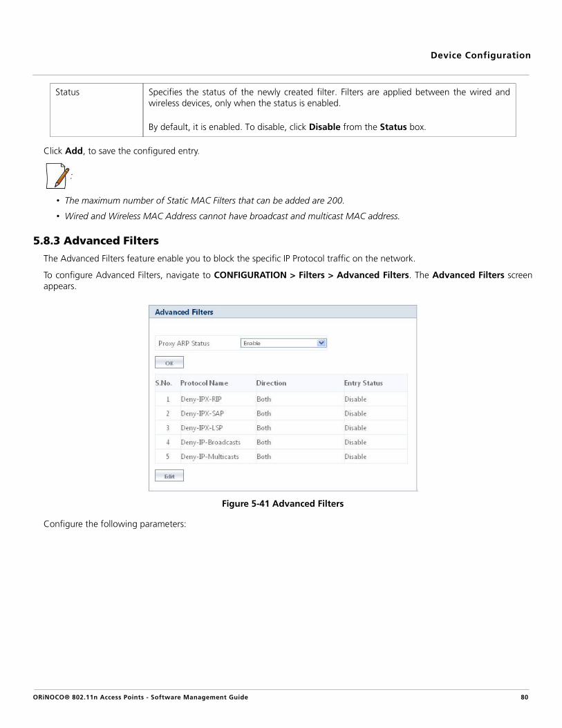
Device Configuration
Click Add, to save the configured entry.
:
• The maximum number of Static MAC Filters that can be added are 200.
• Wired and Wireless MAC Address cannot have broadcast and multicast MAC address.
5.8.3 Advanced Filters
The Advanced Filters feature enable you to block the specific IP Protocol traffic on the network.
To configure Advanced Filters, navigate to CONFIGURATION > Filters > Advanced Filters. The Advanced Filters screenappears.
Figure 5-41 Advanced Filters
Configure the following parameters:
Status Specifies the status of the newly created filter. Filters are applied between the wired andwireless devices, only when the status is enabled.
By default, it is enabled. To disable, click Disable from the Status box.
ORiNOCO® 802.11n Access Points - Software Management Guide 80

Device Configuration
Click OK and COMMIT, to save the configured parameters.
To edit any protocol entry, click Edit. The Advanced Filters - Edit Entries screen appears.
Parameter Description
Proxy ARP Status Specifies the status of the Proxy ARP feature on the AP device. Functioning as a Proxy ARP,the AP device helps:
– To reduce unnecessary flow of broadcast traffic to all the wireless clients, withoutdisturbing every wireless client on the network.
– Power save the wireless clients as they need not wake up for ARP broadcasts.
– The clients to learn the MAC addresses faster
When two clients connected to an AP device tries to communicate, they send an ARPrequest to get the MAC address of the destined client. AP device responds to this ARPrequest and looks for the MAC address of the destined client in its Proxy ARP table. Onfinding the MAC address, AP device forwards it to the client, without disturbing all the otherwireless clients on the network. Client then updates its ARP table with the MAC address andforwards the ICMP packet to the intended wireless client via AP device.
By default, Proxy ARP Status is disabled. To enable this feature, select Enable from thedrop down menu.
Advanced Filter TableAdvance Filter Table contains a list of all protocols on which Advanced Filtering is applied.
Protocol Name Specifies the protocol name that is to be filtered. By default, Advanced Filters are supportedon the following five default protocols:
– Deny-IPX-RIP
– Deny-IPX-SAP
– Deny-IPX-LSP
– Deny-IP-Broadcasts
– Deny-IP-Multicasts
Direction Specifies the direction of an IP Protocol traffic. The direction can be enabled either forethernet to wireless, wireless to ethernet or both ways.
Entry Status Specifies the status of the filter applied on the IP Protocol.
ORiNOCO® 802.11n Access Points - Software Management Guide 81

Device Configuration
Figure 5-42 Advanced Filters - Edit Entries
Modify the Direction and Status of the desired IP Protocol. Click OK and COMMIT, to save the configured parameters.
5.8.4 TCP/UDP Port Filters
Port-based filtering enables you to control wireless user access to network services by selectively blocking TCP/UDP protocolsthrough the device. A user specifies a Protocol Name, Port Number, Port Type (TCP, UDP, or TCP/UDP), and filtering interfaces(Only Wireless, Only Ethernet or Both) in order to block access to services such as Telnet and FTP, and traffic such as NETBIOSand HTTP.
For example, a device with the following configuration would discard frames received on its ethernet interface with a UDPdestination port number of 137, effectively blocking NETBIOS Name Service packets.
Navigate to CONFIGURATION > Filters > TCP/UDP Port Filters. The TCP / UDP Port Filters screen appears.
Protocol Name
Port Number
Port Type
Filter Interface
Entry Status (Enable/Disable)
NETBIOS Name Service
137 UDP Ethernet Enable
ORiNOCO® 802.11n Access Points - Software Management Guide 82

Device Configuration
Figure 5-43 TCP/UDP Port Filters
Tabulated below are the ‘TCP/UDP Port Filter’ parameters and the method to configure the configurable parameters:
Parameter Description
Filter Control Specifies the Filter Control feature on the device.
By default, it is disabled. To configure, select Enable or Disable from the drop down menu.
TCP/UDP Port Filter TableThe TCP/UDP Port Filters screen displays a list of default protocols supported by the device and the protocols createdby the user. By default, the system generates seven protocols entries. Each of the Protocol contains the followinginformation:
Protocol Name Specifies the name of the Protocol.
: The system throws an error when you try to edit the name of a default protocol.
Protocol Number Specifies the TCP/UDP port number.
: The system throws an error when you try to edit the Port number of a defaultprotocol.
Port Type Specifies the type of the port. Select the port type as TCP/UDP/Both from the Port Type box.
By default, Port Type is Both for the default entries and TCP for the newly added entries.
Filter Interface Specifies the parameter used to configure the interface on which the Filter is applied. Selectthe interface as either Only Ethernet, Only Wireless, or All Interfaces from the FilterInterface box.
ORiNOCO® 802.11n Access Points - Software Management Guide 83

Device Configuration
Click OK and COMMIT, to save the configured parameters.
5.8.4.1 Add New Entries to TCP/UDP Port Filter Table
To add user-defined protocols to the TCP/UDP Port Filter Table, click Add in the TCP/UDP Port Filters screen. The TCP/UDPPort Filter Add Row screen appears.
.
Figure 5-44 TCP/UDP Port Filter Table - Add Entries
Provide details for all the parameters and click Add.
: The maximum number of TCP/UDP Port Filters that can be added are 64.
5.8.5 Storm Threshold Filters
The Storm Threshold Filter restricts the excessive inbound multicast or broadcast traffic on layer two interfaces. This protectsagainst broadcast storms resulting from spanning tree mis-configuration. A broadcast/multicast filtering mechanism needs tobe enabled so that a large percentage of the wireless link remains available to the connected mobile terminals.
Navigate to CONFIGURATION > Filters > Storm Threshold Filters. The Storm Threshold Filters screen appears.
Figure 5-45 Storm Threshold Filters
Entry Status Set the entry status as Enable/Disable/Delete.
– Enable: The device filters the TCP/UDP protocols.
– Disable: The device allows all the TCP/UDP protocols.
– Delete: The device deletes a protocol entry from the Filter Table.
: System-defined default protocols entries cannot be deleted.
ORiNOCO® 802.11n Access Points - Software Management Guide 84

Device Configuration
Tabulated below are the ‘Storm Threshold Filter’ parameters and the method to configure the configurable parameters:
Click OK and COMMIT, to save the configured parameters.
: Wireless 2 parameters of Storm Threshold Filters are applicable only to a dual-radio device.
5.8.6 Packet Forwarding
Packet Forwarding is the process of relaying the data packets, through a pre-configured gateway (connected to the APdevice either through ethernet interface or WDS interface). On receiving the traffic (uplink) from the wireless clients, the APdevice forwards the traffic to the destined gateway, by tagging it with the gateway MAC address. The gateway device(configured according to the user requirement) monitors the uplink traffic, for improved security.
Navigate to CONFIGURATION > Filters > Packet Forwarding. The Packet Forwarding screen appears.
Figure 5-46 Packet Forwarding
Tabulated below are the ‘Packet Forwarding’ parameters and the method to configure the configurable parameters:
Parameter Description
Interface Specifies a read - only parameter that represents the type of interface on which filtering hasto be applied. The Storm Threshold filter can be used to filter the traffic on two types ofinterfaces, Ethernet or Wireless.
By default, Storm Threshold filtering is disabled on both ethernet and wireless interfaces.
Multicast Threshold Specifies the threshold value of the multicast packets to be processed for the ethernet orwireless interface. Packets more than threshold value are dropped. If threshold value formulticast packets is set to '0', filtering is disabled.
The default Multicast Threshold value is 0 per second. To configure, enter a value rangingfrom 0 to 65536.
Broadcast Threshold Specifies the threshold value of the broadcast packets to be processed for the ethernet orwireless interface. Packets more than threshold value are dropped. If threshold value forbroadcast packets is set to '0', filtering is disabled.
The default Broadcast Threshold value is 0 per second. To configure, enter a value rangingfrom 0 to 65536.
ORiNOCO® 802.11n Access Points - Software Management Guide 85

Device Configuration
Click OK and COMMIT, to save the configured parameters.
:
• Enabling Packet Forwarding within the same network, stops the communication between all the wireless clients andforwards data to the gateway.
• If the Uplink Port is enabled as ‘Auto’, then only unicast traffic is forwarded to gateway. The multicast and broadcasttraffic is forwarded to wireless clients.
• If the Uplink Port is enabled as ‘Ethernet’ or ‘WDS_X_Y’, then all the traffic (unicast, multicast and broadcast) betweenthe wireless clients is forwarded to gateway.
5.9 DHCPDynamic Host Configuration Protocol (DHCP) is a network protocol that enables a server to assign an IP address to a devicefrom a defined range of IP addresses configured for a given network. It allows you to distribute IP addresses from a centralpoint to various hosts and simplifies the process of configuring the IP addresses to individual hosts.
5.9.1 DHCP Server
DHCP automatically allocates network addresses and also delivers configuration parameters dynamically to the clients fromthe DHCP Server. When DHCP server is enabled, it allows allocation of IP addresses to clients connected to the device.
Navigate to CONFIGURATION > DHCP > DHCP Server. The DHCP Server screen appears.
Parameter Description
Status Specifies the status of Packet Forwarding on the AP device.
By default, it is disabled. To enable, select Enable from the drop down menu.
Gateway MAC Address
Specifies the MAC address of the destined gateway device. To configure, enter theGateway MAC Address in the box.
Uplink Port Name Specifies the port of the gateway, that should participate in Packet Forwarding. TheUplink Port Name can be configured in three ways:
– Auto: Configure the Uplink Port Name to Auto, when the interface of the destinedgateway port is unknown. Based on the configured peer MAC address, the AP deviceautomatically detects the gateway port by checking within its bridge table.
– Ethernet: Configure the Uplink Port Name to Ethernet, when the destined gatewayport is connected on ethernet interface of the AP device.
– WDS: Configure the Uplink Port Name to WDS, when the destined gateway port isconnected on WDS interface of the AP device.
Based on the radio (interface 1 and interface 2) and the VAP enabled, the UpLink Port Nameconfigured in WDS is represented as:
For example, if UpLink Port Name is WDS_1_2 then, 1 represents radio 1 (interface 1) and 2represents VAP 2.
WDS_X_Y; where
X = the radio on which the VAP is enabled (interface 1 or interface 2)
Y = the VAP enabled on a radio (VAP 1, VAP 2......VAP 8)
ORiNOCO® 802.11n Access Points - Software Management Guide 86

Device Configuration
Figure 5-47 DHCP Server
Tabulated below are the ‘DHCP Server’ parameters and the method to configure the configurable parameters:
Parameter Description
DHCP Server Status Specifies the status of the DHCP Server functionality on the device.
By default, it is disabled. To configure, select Enable or Disable from the drop down menu.
: If DHCP Server Status is enabled, it is recommended to set the IP address manually(Static IP Address). See Assigning the IP Address Manually
Max Lease Time Specifies the Maximum Lease time for which the DHCP client can have the IP addressprovided by the DHCP Server.
By default, the Max Lease Time taken is 86400 seconds. To configure, enter a valueranging from 3600-172800 seconds.
Max Lease Time
: If the Maximum Lease time is greater than Default Lease time, then the DHCP serveroffers the interface based configured Default Lease time. Whereas, if the MaximumLease time is less than the Default lease time, then the lease time offered by theDHCP server will be Maximum Lease time.
DHCP Interface SettingsThe DHCP Interface Settings Table contains the following information:
Subnet Mask Specifies the subnet mask to be sent to the client along with the assigned IP address. Thenetmask configured here should be greater than or equal to the netmask configured on theinterface. To configure, enter the Net Mask.
ORiNOCO® 802.11n Access Points - Software Management Guide 87

Device Configuration
Click OK and COMMIT, to save the configured parameters.
5.9.1.1 Add an Entry to DHCP Pool Table
To add an entry to the DHCP Pool Table, click Add in the DHCP Server screen. The DHCP Pool Table Add Row screenappears.
Figure 5-48 DHCP Pool - Add an Entry
Default Gateway Specifies the default gateway to be sent to the client along with the assigned IP Address.Default Gateway is a node that serves as an accessing point to another network. Toconfigure, enter the Default Gateway address.
Primary DNS Specifies the primary DNS (Domain Name Server) IP address to be sent to the client. Toconfigure, enter the Primary DNS address.
Secondary DNS Specifies the secondary DNS IP address to be sent to the client. To configure, enter theSecondary DNS address.
Default Lease Period Specifies the least time offered by the DHCP server, to the client on that interface.
By default, it is taken as 86400 seconds. To configure, enter a value ranging from 3600 to172800 seconds.
Status Specifies the status of DHCP server functionality over the interface.
By default, it is disabled. To configure, select Enable or Disable from the drop down menu.
DHCP Pool TableThe DHCP Pool Table contains the following information:
Start IP Address Specifies the Start IP Address of the pool.
End IP Address Specifies the End IP Address of the pool.
Delete This parameter allows you to delete the added pool entry.
:
• A pool entry can be deleted but not edited.
• To enable DHCP Server, atleast one pool must be configured.
ORiNOCO® 802.11n Access Points - Software Management Guide 88

Device Configuration
Configure the following parameters:
Click Add, to save the added entry.
: You can add a maximum of five pool entries per interface.
Parameter Description
Pool Interface Specifies the interface type (ethernet or wireless). The device supports only Bridge mode.
Start IP Address See DHCP Pool Table
End IP address See DHCP Pool Table
Entry Status Specifies the status of the pool entry being added.
By default, it is enabled. To configure, select Enable or Disable from the drop down menu.
ORiNOCO® 802.11n Access Points - Software Management Guide 89
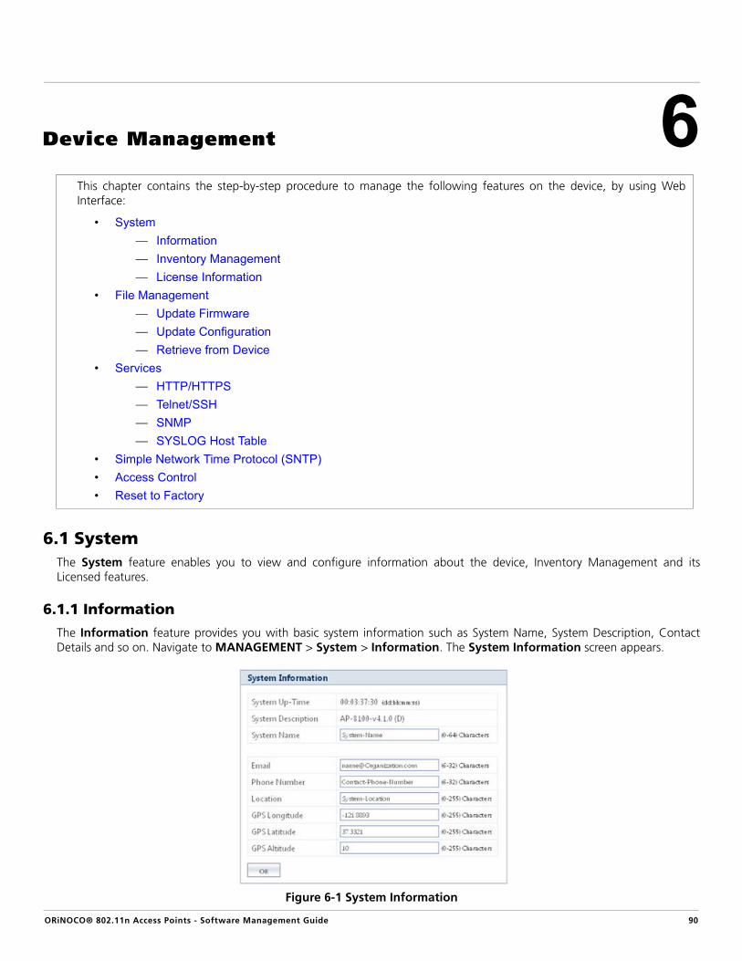
ORiNOCO® 802.11n Access Points - Software Management Guide
6
Device Management6.1 SystemThe System feature enables you to view and configure information about the device, Inventory Management and itsLicensed features.
6.1.1 Information
The Information feature provides you with basic system information such as System Name, System Description, ContactDetails and so on. Navigate to MANAGEMENT > System > Information. The System Information screen appears.
Figure 6-1 System Information
This chapter contains the step-by-step procedure to manage the following features on the device, by using WebInterface:
• System— Information— Inventory Management— License Information
• File Management— Update Firmware— Update Configuration— Retrieve from Device
• Services— HTTP/HTTPS— Telnet/SSH— SNMP— SYSLOG Host Table
• Simple Network Time Protocol (SNTP)• Access Control• Reset to Factory
90

Device Management
In the System Information screen, you can view and configure the following configurable parameters:
Click OK, to save the configured parameters.
6.1.2 Inventory Management
The Inventory Management feature provides inventory information about the device. Navigate to MANAGEMENT > System > Inventory Management. The System Inventory Management Table appears.
Parameter Description
System Up-Time Specifies a read-only parameter that represents the operational time of the device since itslast reboot.
System Description Specifies a read-only parameter that provides description about the system, including thedevice name, current version of the firmware and the current build number.
System Name Specifies the name that is assigned to the device.
To configure, enter a System Name of maximum 64 characters.
Email Specifies the email address of the person administering the device.
To configure, enter an email address of minimum 6 and maximum 32 characters in theEmail box.
Phone Number Specifies the phone number of the person administering the device.
To configure, enter a phone number of minimum 6 and maximum 32 characters in thePhone Number box.
Location Specifies the location where the device is installed.
To configure, enter a location name of minimum 0 and maximum 255 characters in theLocation box.
GPS Longitude Specifies the longitude at which the device is installed.
To configure, enter a longitude value of minimum 0 and maximum 255 characters (in theformat required by your Network Management System) in the GPS Longitude box.
GPS Latitude Specifies the latitude at which the device is installed.
To configure, enter a latitude value of minimum 0 and maximum 255 characters (in theformat required by your Network Management System) in the GPS Latitude box.
GPS Altitude Specifies the altitude at which the device is installed.
To configure, enter an altitude value of minimum 0 and maximum 255 characters (in theformat required by your Network Management System) in the GPS Altitude box.
ORiNOCO® 802.11n Access Points - Software Management Guide 91

Device Management
Figure 6-2 System Inventory Management Table
By default, the components information is auto-generated by the device. This information is standard and is used only forreference purpose. Click Refresh, to view the updated System Inventory Management information.
: Wireless Card 2 is applicable only to dual-radio device.
6.1.3 License Information
Licensing is considered to be the most important component of an enterprise-class device which typically has a feature-basedpricing model. It is also required to prevent the misuse and tampering of the device by a wide-variety of audience whosemotives may be intentional or accidental. Licensed Features are, by default, set by the company.
Navigate to MANAGEMENT > System > License Information. The License Information screen appears.
Figure 6-3 License Information
: The above figure represent the licensed information of AP-8100. Licensed Features vary depending on your device.
You can view the following license information:
ORiNOCO® 802.11n Access Points - Software Management Guide 92

Device Management
6.2 File ManagementBy using File Management feature, you can update the firmware or configuration files on the device, and retrieveconfiguration files from the device through HTTP or TFTP.
HTTP file transfer can be performed with or without SSL enabled. HTTP file transfer with SSL requires enabling SecureManagement and Secure Socket Layer. HTTP file transfer by using SSL may take extra time.
A TFTP server must be running and configured to point to the directory containing the file. The TFTP server must be runningand configured in the desired directory path to copy the retrieved file.
Parameter Description
Product Description Specifies the description of the device.
Number of Radios Specifies the number of radios that the device is licensed to operate.
Number of Ethernet Interfaces
Specifies the number of ethernet interfaces available on the device.
Radio 1 allowed ‘Frequency Band’
Specifies the operational wireless frequency band supported by the device on Radio 1.
Radio 2 allowed ‘Frequency Band’
Specifies the operational wireless frequency band supported by the device on Radio 2.
: Radio 2 is applicable only to a dual-radio device.
Maximum Output Bandwidth
Specifies the maximum output bandwidth limit of the device. It is represented in Mbps.
Maximum Input Bandwidth
Specifies the maximum input bandwidth limit of the device. It is represented in Mbps.
: The Input and Output Bandwidth features are referred with respect to the wirelessinterface. That is, input bandwidth refers to the data received on the wirelessinterface and output bandwidth refers to the data sent out of the wireless interface.
Maximum Aggregate Bandwidth
Specifies the cumulative bandwidth of the device which is the sum of configured output andinput.
Product Family Specifies the product family of the device.
Product Class Specifies the product class of the device. ORiNOCO® 802.11n Access Points are indoordevices.
Allowed Operational Modes of Radio 1
Specifies the operational modes allowed on the wireless interface (radio) 1.
Allowed Operational Modes of Radio 2
Specifies the operational modes allowed on the wireless interface (radio) 2.
: Radio 2 is applicable only to a dual-radio device.
MAC Address of the Device
Specifies the MAC address of the device.
ORiNOCO® 802.11n Access Points - Software Management Guide 93

Device Management
6.2.1 Update Firmware
6.2.1.1 Update Firmware by Using HTTP
To update the firmware by using HTTP, follow the following steps:
1. Navigate to MANAGEMENT > File Management > Update Firmware > HTTP. The configuration screen appears:
Figure 6-4 Update Firmware by using HTTP
2. In the HTTP screen, click Browse to select the updated firmware file from the desired location.
: The file name should not contain any spaces or special characters.
3. Click Update & Reboot, for the device to get uploaded with new firmware and reboot automatically.
:
• Update & Reboot is applicable only to AP-8100.
• For AP-800 and AP-8000, click Update to load the firmware on to the device and Reboot the device.
6.2.1.2 Update Firmware by Using TFTP
To update the firmware by using TFTP, follow the following steps:
1. Navigate to MANAGEMENT > File Management > Update Firmware > TFTP. The configuration screen appears:
Figure 6-5 Update Firmware by using TFTP
ORiNOCO® 802.11n Access Points - Software Management Guide 94
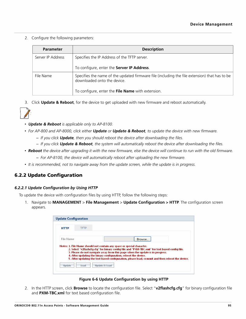
Device Management
2. Configure the following parameters:
3. Click Update & Reboot, for the device to get uploaded with new firmware and reboot automatically.
:
• Update & Reboot is applicable only to AP-8100.
• For AP-800 and AP-8000, click either Update or Update & Reboot, to update the device with new firmware.
– If you click Update, then you should reboot the device after downloading the files.
– If you click Update & Reboot, the system will automatically reboot the device after downloading the files.
• Reboot the device after upgrading it with the new firmware, else the device will continue to run with the old firmware.
– For AP-8100, the device will automatically reboot after uploading the new firmware.
• It is recommended, not to navigate away from the update screen, while the update is in progress.
6.2.2 Update Configuration
6.2.2.1 Update Configuration by Using HTTP
To update the device with configuration files by using HTTP, follow the following steps:
1. Navigate to MANAGEMENT > File Management > Update Configuration > HTTP. The configuration screen appears.
Figure 6-6 Update Configuration by using HTTP
2. In the HTTP screen, click Browse to locate the configuration file. Select “v2flashcfg.cfg” for binary configuration file and PXM-TBC.xml for text based configuration file.
Parameter Description
Server IP Address Specifies the IP Address of the TFTP server.
To configure, enter the Server IP Address.
File Name Specifies the name of the updated firmware file (including the file extension) that has to bedownloaded onto the device.
To configure, enter the File Name with extension.
ORiNOCO® 802.11n Access Points - Software Management Guide 95

Device Management
: The file name should not contain any spaces or special characters.
3. Click Update, to update the device with new configuration file.
4. Click Load, to apply the updated changes.
5. Click Update & Load, to update and load the configuration file on the device with a single operation.
:
• Reboot the device when you update the device with Binary Configuration file.
• For a Text Based Configuration File, either Update and Load the device or click Update & Load.
• It is recommended not to navigate away from the update screen while the update is in progress.
6.2.2.2 Update Configuration by Using TFTP
To update the device with configuration files by using TFTP, follow the following steps:
1. Navigate to MANAGEMENT > File Management > Update Configuration > TFTP.
2. You can update the device with two configuration files: Binary Config and Text Based Config.
3. To update the device with Binary Configuration file, select Binary Config radio button, the configuration screen appears.
Figure 6-7 Update Configuration by using TFTP - Binary Config
Configure the following parameters.
Parameter Description
Server IP Address Specifies the IP Address of the TFTP server.
To configure, enter the Server IP Address.
File Name Specifies the name of the Binary file (including the file extension) that has to bedownloaded onto the device.
To configure, enter the Binary File Name with extension.
ORiNOCO® 802.11n Access Points - Software Management Guide 96

Device Management
4. Click Update, to update the device with new configuration.
5. Click Update & Reboot, to update and automatically reboot the device.
6. To update the device with Text Based Configuration files, select Text Based Config and configuration screen appears:
Figure 6-8 Update Configuration by using TFTP - Text Based Config
Configure the following parameters.
7. Click Update, to update the device with new configuration file.
8. Click Load, to apply the updated changes.
9. Click Update & Load, to update and load the configuration file onto the device.
:
• Reboot the device when you update the device with Binary Configuration file.
• Update & Load the device when you update the device with Text Based Configuration file.
• It is recommended not to navigate away from the update screen while the update is in progress.
6.2.3 Retrieve from Device
6.2.3.1 Retrieve from Device by using HTTP
To retrieve Configuration files, Event Logs and Text Based Templates from the device by using HTTP, follow the following steps:
1. Navigate to MANAGEMENT > File Management > Retrieve from Device > HTTP. The configuration screen appears.
Parameter Description
Server IP Address Specifies the IP Address of the TFTP server.
To configure, enter the Server IP Address.
File Name Specifies the name of the Text based file (including the file extension) that has to bedownloaded onto the device.
To configure, enter the Text based File Name with extension.
ORiNOCO® 802.11n Access Points - Software Management Guide 97

Device Management
Figure 6-9 Retrieve From Device by using HTTP
2. Configure the following parameters:
3. Click Retrieve, the Download screen appears.
Figure 6-10 Download
4. Right-click the Download link to save or retrieve the file to the desired location.
: When the device is operational with default factory settings, there is no Config file present and hence it cannot beretrieved
6.2.3.2 Retrieve from Device by using TFTP
To retrieve Configuration files, Event Logs and Text Based Templates from the device by using TFTP, follow the following steps:
1. Navigate to MANAGEMENT > File Management > Retrieve from Device > TFTP. The configuration screen appears:
Parameter Description
File Type Specifies the type of file that you want to retrieve from the device. You can retrieve thefollowing file types:
– Config: Specifies the configuration files of the device.
– Event Log: Specifies the Event Logs from the device.
– Text Based Template Config: Represents the Text Based Template Configuration files of the device.
To configure, select the File Type from the drop down menu.
ORiNOCO® 802.11n Access Points - Software Management Guide 98

Device Management
Figure 6-11 Retrieve From Device by using TFTP
2. Configure the following parameters:
3. Click Retrieve.
: When the device is operational with default factory settings, there is no Config file present and hence it cannot beretrieved.
6.2.3.3 Text Based Configuration (TBC) File Management
Text Based Configuration (TBC) file is a simple text file that holds device template configurations. The device supports the TBCfile in XML format which can be edited in any XML or text editors. You can generate the TBC file from the CLI Session andmanually edit the configurations and then load the edited TBC file to the device so that the edited configurations are appliedonto the device. It differs mainly from the binary configuration file in terms of manual edition of configurations. Thegenerated TBC file is a template which has only the default and modified configurations on the live CLI session.
Parameter Description
Server IP Address Specifies the IP Address of the TFTP server.
To configure, enter the Server IP Address.
File Name Specifies the name of the file (including the file extension) that has to be retrieved from thedevice.
To configure, enter the File Name with extension.
File Type Specifies the file type that you want to retrieve from the device. You can retrieve any of thefollowing file types:
– Config: Specifies the configuration files of the device.
– Event Log: Specifies the Event Logs from the device.
– Text Based Template Config: Specifies the Text Based Template Configuration (TBC) files of the device. TBC template can be used to configure the parameters and retrieve the configuration to the device.
To configure, select the File Type from the drop down menu.
ORiNOCO® 802.11n Access Points - Software Management Guide 99

Device Management
1. Generating TBC File
The TBC file is generated through CLI by executing generate command. While generating the TBC file from CLI, there is anoption to generate it with or without all Management and Security Passwords. The management passwords includeCLI/WEB/SNMP passwords. The security passwords include Network-Secret/Encryption-Key(s)/RADIUS-Shared-Secret. Ifincluded, these passwords become a part of the generated TBC file and are in a readable form. If excluded, all thesepasswords are not part of the generated TBC file. The commands used for the generation of TBC file are:
AP-00:7D:09>enable
AP-00:7D:09# generate ?
Possible completions:
tbc-with-pwds Generate Text Based Template Config file with keys/passwords
tbc-without-pwds Generate Text Based Template Config file without keys/passwords
The generated TBC file contains,
• Default configurations.
• Any user-added or edited configurations on current live CLI session.
The generated Text Based Template Configuration file appears as shown below:
Figure 6-12 TBC File in XML Format
2. Editing the TBC File
The TBC file can easily be opened and edited in any standard Text-Editors like Wordpad, MS-Word, Notepad++, StandardXML Editors. Proxim recommends XML Notepad 7 editor for editing the TBC file. Do the following to edit the TBC file.
• You can modify any value between the double quotes(““) in the TBC file. It is recommended not to change thetext outside the double quotes (“”) or XML tags in the TBC file.
• Remove unchanged configurations from the TBC file before loading onto the device.
ORiNOCO® 802.11n Access Points - Software Management Guide 100

Device Management
3. Loading the TBC file
The TBC file can be loaded onto the device by using either SNMP, Web Interface or CLI. You can either use TFTP or HTTP toload the TBC file. By using Web Interface, you can load the TBC file by navigating to MANAGEMENT > FileManagement > Upgrade Configuration. To load the TBC file, it should be generated or downloaded onto the device.While loading the TBC file onto the device, any file name is accepted. Once loaded, the TBC file name is renamed toPXM-TBC.xml.
If the TBC file does not contain correct XML syntax, the file will be discarded with DOM error and no configurations will beloaded. All duplicate values entered are considered as errors while loading and syslogs will be generated accordingly.Therefore, it is recommended to delete all unchanged parameters from the TBC file during its edition. Commit is requiredto retain the configurations across reboots after loading the TBC file.
: Both Commit and Reboot are required to accept the modifications done in the TBC File. Only reboot is required to reject the modifications.
Loading the TBC file is allowed only once in an active device session (that is, if TBC file is loaded, reboot is required toapply all configurations or to load another TBC file). All configurations in the TBC file are loaded to the device irrespectiveof their default or modified or added configurations. Loading the TBC file takes approximately 10-20 seconds dependingon the number of configurations added.
:
• Remove any unmodified parameters from the TBC file, before loading it.
• If you get any time-out errors while loading TBC file from SNMP interface, increase the time-out value to more than 30 seconds in the MIB Browser.
6.3 ServicesThe Services feature allows you to configure the management interface (HTTP/HTTPS, Telnet/SSH and SNMP) and SYSLOGHost Table parameters that prevent from unauthorized access to the device.
6.3.1 HTTP/HTTPS
Navigate to MANAGEMENT > Services > HTTP/HTTPS. The configuration screen appears.
Figure 6-13 HTTP/HTTPS
ORiNOCO® 802.11n Access Points - Software Management Guide 101

Device Management
Configure the following parameters in the HTTP/HTTPS screen:
Click OK and then Reboot the device for the changes to take effect.
6.3.2 Telnet/SSH
Navigate to MANAGEMENT > Services > Telnet/SSH. The configuration screen appears.
Figure 6-14 Telnet/SSH
Parameter Description
Password Specifies the password, essential to access the device by using web interface.
By default, the password is set to public. To configure, enter a new password in thePassword box. The password should be alphanumeric with minimum of 6 and maximum of32 characters.
: Special characters like - = \ " ' ? / space are not allowed in the password.
HTTP Specifies the HTTP status. HTTP allows the user to access the device through a webinterface.
To configure, Select Enable or Disable from the drop down menu.
HTTP Port Specifies the port number for the HTTP interface.
By default, the port number is 80. To configure, enter a new HTTP Port.
HTTPS Specifies the HTTPS status. HTTPS allows the user to access the device through a webinterface.
To configure, select Enable or Disable from the drop down menu. The passwordconfiguration for HTTPS is same as configured for HTTP.
ORiNOCO® 802.11n Access Points - Software Management Guide 102
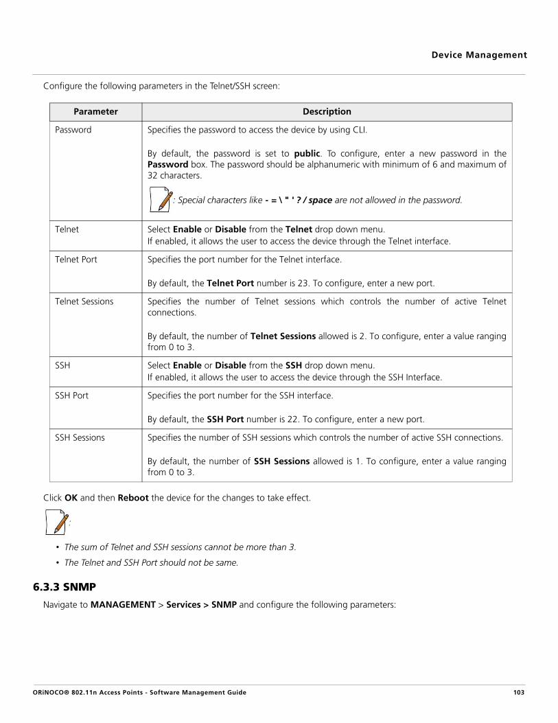
Device Management
Configure the following parameters in the Telnet/SSH screen:
Click OK and then Reboot the device for the changes to take effect.
:
• The sum of Telnet and SSH sessions cannot be more than 3.
• The Telnet and SSH Port should not be same.
6.3.3 SNMP
Navigate to MANAGEMENT > Services > SNMP and configure the following parameters:
Parameter Description
Password Specifies the password to access the device by using CLI.
By default, the password is set to public. To configure, enter a new password in thePassword box. The password should be alphanumeric with minimum of 6 and maximum of32 characters.
: Special characters like - = \ " ' ? / space are not allowed in the password.
Telnet Select Enable or Disable from the Telnet drop down menu. If enabled, it allows the user to access the device through the Telnet interface.
Telnet Port Specifies the port number for the Telnet interface.
By default, the Telnet Port number is 23. To configure, enter a new port.
Telnet Sessions Specifies the number of Telnet sessions which controls the number of active Telnetconnections.
By default, the number of Telnet Sessions allowed is 2. To configure, enter a value rangingfrom 0 to 3.
SSH Select Enable or Disable from the SSH drop down menu. If enabled, it allows the user to access the device through the SSH Interface.
SSH Port Specifies the port number for the SSH interface.
By default, the SSH Port number is 22. To configure, enter a new port.
SSH Sessions Specifies the number of SSH sessions which controls the number of active SSH connections.
By default, the number of SSH Sessions allowed is 1. To configure, enter a value rangingfrom 0 to 3.
ORiNOCO® 802.11n Access Points - Software Management Guide 103
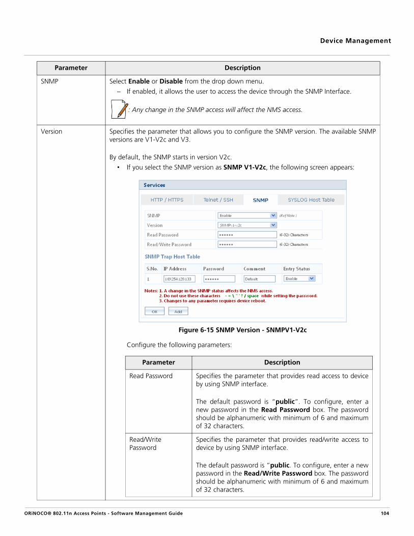
Device Management
Parameter Description
SNMP Select Enable or Disable from the drop down menu.
– If enabled, it allows the user to access the device through the SNMP Interface.
: Any change in the SNMP access will affect the NMS access.
Version Specifies the parameter that allows you to configure the SNMP version. The available SNMPversions are V1-V2c and V3.
By default, the SNMP starts in version V2c.
• If you select the SNMP version as SNMP V1-V2c, the following screen appears:
Figure 6-15 SNMP Version - SNMPV1-V2c
Configure the following parameters:
Parameter Description
Read Password Specifies the parameter that provides read access to deviceby using SNMP interface.
The default password is “public”. To configure, enter anew password in the Read Password box. The passwordshould be alphanumeric with minimum of 6 and maximumof 32 characters.
Read/Write Password
Specifies the parameter that provides read/write access todevice by using SNMP interface.
The default password is “public. To configure, enter a newpassword in the Read/Write Password box. The passwordshould be alphanumeric with minimum of 6 and maximumof 32 characters.
ORiNOCO® 802.11n Access Points - Software Management Guide 104

Device Management
• If you select the SNMP version as SNMP V3, then following screen appears:
Figure 6-16 SNMP Version - SNMPV3
Configure the following parameters:
Parameter Description
Security Level Specifies the security level of the device. The supportedSecurity Levels for the device are:
– None: For no authentication
– AuthNoPriv: For Extensible Authentication
– AuthPriv: For both Authentication and Privacy (Encryption)
By default, it is taken as AuthPriv. To configure, select theSecurity Level, from the drop down menu.
Priv Protocol Specifies the type of privacy (or encryption) protocol.
By, default Priv Protocol is AES-128. To configure, selectthe encryption standard as either AES-128 (AdvancedEncryption Standard) or DES (Data Encryption Standard)from the drop down menu.
: Applicable only when the Security Level is set toAuthPriv.
ORiNOCO® 802.11n Access Points - Software Management Guide 105

Device Management
Click OK and Reboot the device, if you have changed the values in the SNMP Trap Host Table.
6.3.3.1 Add a new Entry to the SNMP Trap Host Table
To add new entries in the SNMP Trap Host Table, click Add. The SNMP Trap Host Table Add Row screen appears.
Version
Click OK and Reboot the device, to save the configured parameters.
SNMP Trap Host TableThe SNMP Trap Host Table contains the following information:
IP Address Specifies the IP address to which SNMP traps will be delivered.
Password Specifies the password set to access the SNMP Trap Host Table entry.
: Applicable only to SNMP V1-V2c.
Comment Specifies the user-comment on the SNMP Trap Host Table entry.
To configure, enter any comment on the table entry.
Entry Status Specifies the entry status set for each table entry.
To configure, select either Enable, Disable or Delete.
– If Enabled, it allows the device to send SNMP traps to the specified IP address.
– If you want to delete any table entry from the SNMP Trap Host Table, select Delete.
Priv Password Specifies the pass key for Privacy protocol selected.
The default password is public123. To configure, enter anew password ranging from 8 to 32 characters.
: Applicable only when the Security Level is set toAuthPriv.
Auth Protocol Specifies the type of Authentication protocol.
By default, Auth Protocol is SHA. To configure, select theencryption standard as either SHA (Secure Hash Algorithm)or MD5 (Message-Digest algorithm).
Auth Password Specifies the pass key for Privacy protocol selected.
The default password is public123. To configure, enter anew password ranging from 8 to 32 characters.
ORiNOCO® 802.11n Access Points - Software Management Guide 106

Device Management
Figure 6-17 SNMP Trap Host Table Add Row
Configure the following parameters:
Click Add, to add an entry in the SNMP Trap Host Table.
6.3.4 SYSLOG Host Table
System log messages are generated by the device by sending requests at various instances to the system log server. Thesystem log messages are lost on device reboot. Navigate to MANAGEMENT > Services > SYSLOG Host Table
Figure 6-18 SYSLOG Host Table
Parameter Description
IP Address Enter the IP address to which SNMP traps will be delivered, in the IP Address box.
Password To access SNMP traps, enter password in the Password box. A minimum of 6 and amaximum of 32 characters are allowed.
: Applicable only to SNMP version “SNMP V1-V2c”.
Comment Enter any comments in the Comment box.
Entry Status Select the Entry Status as either Enable or Disable from the drop down menu.
ORiNOCO® 802.11n Access Points - Software Management Guide 107

Device Management
Configure the following parameters:
Click OK and COMMIT, to save the configured parameters.
6.3.4.1 Add a new Entry to the SYSLOG Host Table
To add new entries in the SYSLOG Host Table, click Add. The SYSLOG Host Table Add Row screen appears.
Parameter Description
Log Status Specifies the status of the system log.
To configure, select either Enable or Disable from the drop down menu. If enabled, itallows the device to generate log messages.
Log Priority Specifies the priority assigned to the log. The available log priorities are:
– Emergency
– Alert
– Critical
– Error
– Warning
– Notice
– Info
– Debug
Please note that the priorities are listed in the order of their severity, where Emergency takesthe highest severity and Debug the lowest.
To configure, select the Log Priority from the drop down menu.
SYSLOG Host Table EntriesThe SYSLOG Host Entries Table contains the following information:
IP Address Specifies the IP address of the SYSLOG server.
Port Specifies the host port number. The default port is 514.
: The user must configure the correct port number on which the SYSLOG server isrunning for the Host Port parameter. Choice of port number must be in line with thestandards for port number assignments defined by Internet Assigned NumbersAuthority (IANA).
Host Comment Specifies the user-comment on the SYSLOG Host Table entry.
To configure, enter any comment on the table entry.
Entry Status Specifies the entry status set for each table entry.
To configure, select either Enable, Disable or Delete.
– If Enabled, it allows the device to send SysLog messages to the specified IP address of the SYSLOG server.
– If you want to delete any table entry from the SYSLOG Host Table, select Delete.
ORiNOCO® 802.11n Access Points - Software Management Guide 108

Device Management
Figure 6-19 SYSLOG Host Table Add Row
Configure the following parameters:
Click Add, to add an entry in the SYSLOG Host Table.
6.4 Simple Network Time Protocol (SNTP)SNTP allows you to synchronize the date and time of the device with the configured time servers. When this feature isenabled, the device will attempt to retrieve the time of day information from the configured time servers (primary orsecondary) and, if successful, will update the relevant time objects in the device. Use the following commands to configureand view the Simple Network Time Protocol.
Navigate to MANAGEMENT > SNTP. The SNTP screen appears.
Figure 6-20 SNTP
You can view and configure the following configurable parameters:
Parameter Description
IP Address Enter the IP address of the SYSLOG server in the IP Address box.
Host Port Enter a Host Port in the Host Port box. The value ranges from 0 to 65535.
Comment Enter any comments in the Comment box.
ORiNOCO® 802.11n Access Points - Software Management Guide 109

Device Management
Click OK and COMMIT, to save the configured parameters.
: Configure the parameters, namely, Primary Server IP Address / Domain Name, Secondary Server IP Address / DomainName, Time zone and Day Light Saving Time, only when the SNTP status is enabled.
6.5 Access ControlThe Management Access Control feature allows you to manage the device from the specified host.
To configure, navigate to MANAGEMENT > Access Control. The Management Access Control Table screen appears.
Figure 6-21 Management Access Control Table
Parameter Description
Enable SNTP Status Specifies the status of the SNTP feature on the device.
Select the Enable SNTP Status checkbox to synchronize the date and time of the devicewith the SNTP time server.
Primary Server IP Address / Domain Name
Specifies the host name or the IP address of the primary SNTP server.
To configure, enter the Primary Server IP Address/Domain Name.
Secondary Server IP Address / Domain Name
Specifies the host name or the IP address of the secondary SNTP server.
To configure, enter the Secondary Server IP Address/Domain Name.
Time Zone Specifies the time zone set for the SNTP.
To configure, select the desired time zone from the drop down menu
Day Light Saving Time
Specifies the number of hours adjusted for the Daylight Saving Time.
To configure, select the desired Day Light Saving Time from the drop down menu.
Current Date/Time Specifies a read-only parameter which displays the system current date and time.
– If SNTP is not enabled, the current date and time are automatically generated from the local system.
– If SNTP is enabled, it displays the time, which the device has obtained from the SNTP server.
ORiNOCO® 802.11n Access Points - Software Management Guide 110

Device Management
Configure the following parameters:
Click OK and Reboot the device, if you have changed the values in the Access Control Table.
6.5.1 Add a new Entry to the Access Control Table
To add new entries to the Access Control Table, click Add in the Management Access Control Table screen. TheManagement Access Table Add Row screen appears:
Figure 6-22 Management Access Control - Add Row
Configure the following parameters:
Click Add, to add an entry.
:
• Applicable only to SNMP V1-V2c.You can enter a maximum of five IP addresses to manage the device.
• You can add new entries only when the Access Table status is enabled.
6.6 Reset to FactoryThe ‘Reset to Factory’ feature allows you to reset the device to its factory default state. When this operation is performed, thedevice will reboot automatically and comes up with default configurations.
Parameter Description
Access Table Status Specifies the status of the Access Control on the AP device.
By default, the Management Access Control is disabled on the device. To enable it, selectEnable from the drop down menu.
IP Address Specifies the IP address of the machine that would manage the device.
Entry Status Specifies the status of the added entry.
To configure, select Enable or Disable from the drop down menu.
Parameter Description
IP Address Enter the IP address of the machine that would manage the device, in the IP Address box.
Entry Status By default the entry status is enabled. To configure, select the status form the drop downmenu.
ORiNOCO® 802.11n Access Points - Software Management Guide 111

Device Management
To reset the device to its factory defaults, navigate to MANAGEMENT > Reset To Factory. The Factory Reset screenappears.
Figure 6-23 Reset to Factory
Then, Click OK for the device to restart with the default factory configuration.
ORiNOCO® 802.11n Access Points - Software Management Guide 112

ORiNOCO® 802.11n Access Points - Software Management Guide
7
Device MonitoringNote that you can also monitor the device by using other interfaces like CLI and SNMP.
7.1 Interface StatisticsInterface Statistics allow you to monitor the status and performance of the Ethernet and Wireless interfaces of the device.
To view interface statistics, navigate to MONITOR > Interface Statistics. The Interface Statistics screen appears.
This chapter contains the step-by-step procedure to monitor the following features on the device, by using WebInterface:
• Interface Statistics• Station Statistics• Rogue Scan Statistics• Bridge
— Bridge Statistics— Learn Table
• Network Layer— IP Address Resolution Protocol (ARP)— Internet Control Message Protocol (ICMP) Statistics
• RADIUS— Authentication Statistics— Accounting Statistics
• Logs— Event Log— SysLog
• SNMP V3 Statistics
: All the interface (radio) 2 parameters discussed in this chapter are applicable only to a dual-radiodevice.
113

Device Monitoring
Figure 7-1 Ethernet Interface Statistics
To view Ethernet statistics, click Ethernet in the Interface Statistics screen. The following Ethernet statistics are displayed.
Ethernet Interface Statistics
Parameter Description
Type Specifies the type of interface.
MTU Specifies the largest size of the data packet sent on the bridge.
Physical Address Specifies the MAC address at the interface protocol layer.
Operational Status Specifies the current operational status of the ethernet interface.
In Octets Specifies the total number of octets received on the interface.
In Unicast Packets Specifies the number of unicast subnetwork packets delivered at the higher level protocol.
In Non-Unicast Packets
Specifies the number of non-unicast subnetwork packets delivered at the higher levelprotocol.
In Errors Specifies the number of inbound packets with errors and that are restricted from beingdelivered.
Out Octets Specifies the total number of octets transmitted out of the interface.
Out Unicast Packets Specifies the total number of packets requested by the higher level protocol and thentransmitted to the non-unicast address.
ORiNOCO® 802.11n Access Points - Software Management Guide 114

Device Monitoring
To view Wireless statistics, click Wireless1/Wireless2 in the Interface Statistics screen. The following Wireless statisticsscreen appears based on radio mode (AP).
Figure 7-2 Wireless1/Wireless2 Interface Statistics
Out Discards Specifies the number of error-free outbound packets which are discarded to prevent themfrom being transmitted. One possible reason for discarding such a packet could be to free upbuffer space.
Out Errors Specifies the number of outbound error packets that are not allowed to transmit.
Receive CRC Errors Specifies the total number of CRC errors occurred if the data sent is corrupted.
Collision Frames Specifies the total number of collision frames.
Career Sense Errors Specifies the total number of frames that are not transmitted.
Frames Too Long Specifies the total number of frames, which are too long than the configured packet size.
Deferred Transmissions
Specifies the total number of times the interface fails to transmit a frame.
MAC Transmit Errors Specifies the total number of frames that do not get transmitted due to the MAC sub-layertransmit error.
ORiNOCO® 802.11n Access Points - Software Management Guide 115

Device Monitoring
View the following Interface statistics and VAP specific statistics.
Click Refresh to view the updated Interface statistics (Ethernet/Wireless 1/Wireless 2) and click Clear to clear the interfacestatistics.
: Wireless interface 2 is only applicable to a dual-radio device.
7.2 Station StatisticsStation Statistics allows you to monitor the status of the wireless clients associated with the device.
To view the station statistics, navigate to MONITOR > Station Statistics. The Station Statistics screen appears.
Wireless 1/Wireless 2 Interface Statistics
Parameter Description
Operational Status Specifies the current operational status of the interface.
In Errors Specifies the number of inbound packets with errors and that are restricted from beingdelivered.
Out Errors Specifies the number of outbound error packets that are not allowed to transmit.
Tx Multicast Frames Specifies the total number of multicast frames transmitted
Tx Discarded Frames Specifies the total number of multicast frames discarded.
Tx Retry Count Specifies the total number of frames delivered with one or more retransmissions.
Tx RTS Frames Specifies the total number of requests for the RTS frames transmission.
Tx RTS Failures Specifies the total number of RTS frames requests that receive no response.
Tx Fragment Count Specifies the total number of transmitted and acknowledged fragments.
Rx Fragment Count Specifies the total number of fragments transmitted and received successfully.
Tx Failed Count Specifies the total number of undelivered frames.
Duplicate Frame Count
Specifies the total number of frames transmitted successfully, in a duplicate fragment.
VAP Statistics
In Octets Specifies the total number of octets received on the interface.
In Unicast Packets Specifies the number of unicast subnetwork packets delivered at the higher level protocol.
In Non - Unicast Packets
Specifies the number of non-unicast subnetwork packets delivered at the higher levelprotocol.
Out Octets Specifies the total number of octets transmitted out of the interface.
Out Unicast Packets Specifies the total number of packets requested by the higher level protocol and thentransmitted to the non-unicast address.
Out Discards Specifies the number of error-free outbound packets which are discarded to prevent themfrom being transmitted. One possible reason for discarding such a packet could be to free upbuffer space.
ORiNOCO® 802.11n Access Points - Software Management Guide 116

Device Monitoring
Figure 7-3 Station Statistics
The Station Statistics screen contains the following information:
To view detailed station statistics, click Edit icon. The configuration screen appears:
Parameter Description
MAC Address Specifies the MAC address of the wireless client.
IP Address Specifies the IP address of the wireless client.
:
• IP Address is not applicable for a WDS enabled wireless client. By default, it is taken as “0.0.0.0”.
• IP Address is not applicable, if Proxy ARP is disabled.
VAP Number Specifies the number of the VAP, enabled on either interface 1 or interface 2. Every interfacesupports upto eight VAPs.
VAP Type Specifies the type of the VAP enabled.
RSSI Specifies the strength of the signal received by the wireless client. The signal strengthdetected by the radio of the device, varies between the values 0 - 128. The higher the value,the greater is the received signal strength.
Tx Rate (Mbps) Specifies the rate at which the last data packet was received.
State Specifies the present status of the wireless client.
Disassociate Specifies the parameter that allows you to disassociate a particular client from the device.
: Disassociate option is not applicable on a WDS enabled wireless client.
ORiNOCO® 802.11n Access Points - Software Management Guide 117

Device Monitoring
Figure 7-4 Station Statistics - Edit
: All the above parameters are the values taken with respect to a particular access point client.
Click Refresh, to view the updated Station Statistics.
7.3 Rogue Scan StatisticsRogue Scan allows you to monitor all the wireless devices (AP/STA/WDS/ADHOC) and rogue AP Devices detected, within thevicinity of your device. It provides with the statistics of all the devices detected under Current Channel Scan Mode or AllChannel Scan Mode. Depending on the device type (AP, STA, Adhoc, WDS and Other devices) selected from the drop downmenu, the Rogue Scan Statistics are displayed.
To view, navigate to MONITOR > Rogue Scan > Interface 1. The Rogue Scan Statistics screen appears.
ORiNOCO® 802.11n Access Points - Software Management Guide 118

Device Monitoring
Figure 7-5 Wireless Interface-1 Rogue Scan Statistics
The Rogue Scan Statistics screen, contains the following information:
Click Refresh, to view the updated Rogue Scan Statistics and click Clear, to clear the Rogue Scan Statistics.
Parameter Description
SSID Specifies the SSID of the detected device.
MAC Address (BSSID)
Specifies the MAC address of the detected device.
Device Type Specifies the Device type (AP, STA, Adhoc, WDS and other devices) detected.
Channel Specifies the channel of the detected device.
Security Specifies the security applied on the detected device. Tabulated below are the correspondingencryption types / authentication modes for the security applied on the scanned device.
TSLF Specifies the time period since the last frame has been received (TSLF) over the channel. It isrecorded in dd : hh : mm : ss (days: hours: minutes: seconds)
RSSI Specifies the strength of the signal received by the detected device. The signal strengthdetected by the radio of the device, varies between the values 0 - 128. The higher the value,the greater is the received signal strength.
Security Encryption Type / Authentication Mode
None No security
WEP WEP / Dot1x
WPA PSK-TKIP / Dot1x TKIP
WPA2 PSK-AES / Dot1x AES
Other / WEP Other
ORiNOCO® 802.11n Access Points - Software Management Guide 119

Device Monitoring
7.4 BridgeThe device serves as a bridge between the wired and the wireless networking devices.
7.4.1 Bridge Statistics
The Bridge Statistics allows you to monitor the statistics of the Bridge.
To view bridge statistics, navigate to MONITOR > Bridge > Bridge Statistics. The Bridge Statistics screen appears.
Figure 7-6 Bridge Statistics
The Bridge Statistics screen contains the following information:
Parameter Description
Description Specifies the description about the bridge.
Type Specifies the type of interface.
MTU Specifies the largest size of the data packet sent on the bridge.
Physical Address Specifies the MAC address at the bridge protocol layer.
Operational Status Specifies the current operational status of the bridge.
In Octets Specifies the total number of octets received on the bridge.
In Unicast Packets Specifies the number of unicast subnetwork packets delivered to the higher level protocol.
In Non-Unicast Packets
Specifies the number of non-unicast subnetwork packets delivered to the higher levelprotocol.
In Errors Specifies the number of inbound packets with errors and that are restricted from beingdelivered.
ORiNOCO® 802.11n Access Points - Software Management Guide 120

Device Monitoring
Click Refresh, to view updated Bridge statistics and click Clear, to clear the Bridge statistics.
7.4.2 Learn Table
Learn Table allows you to view all the MAC addresses that the device has learnt on all of its interfaces. There can be up to10,000 entries in the Learn Table. To view Learn Table statistics, navigate to MONITOR > Bridge > Learn Table. The LearnTable screen appears.
Figure 7-7 Learn Table
The Learn Table displays the MAC address of the learnt device, the bridge port number, aging timer for each device learnt onan interface, and the local (DUT's local interfaces)/remote (learned entries through bridging) status of the learnt device.
Click Refresh, to view updated Learn Table statistics and click Clear, to clear the Learn Table statistics.
7.5 Network Layer
7.5.1 IP Address Resolution Protocol (ARP)
Address Resolution Protocol (ARP) is a protocol for mapping an Internet Protocol address (IP address) to a physical machineaddress on the network. The IP ARP table is used to maintain a correlation between each IP address and its correspondingMAC address. ARP provides the protocol rules for making this correlation and providing address conversion in both directions.
To view IP Address Resolution Protocol (ARP) statistics, navigate to MONITOR > Network Layer > IP ARP. The IP ARP Tablescreen appears.
Out Octets Specifies the total number of octets transmitted out of the bridge.
Out Unicast Packets Specifies the total number of packets requested by the higher level protocol and thentransmitted to the non-unicast address.
Out Discards Specifies the number of error-free outbound packets which are discarded to prevent themfrom being transmitted. One possible reason for discarding such a packet could be to free upbuffer space.
Out Errors Specifies the number of outbound error packets that are not allowed to transmit.
ORiNOCO® 802.11n Access Points - Software Management Guide 121

Device Monitoring
Figure 7-8 IP ARP Statistics
The IP ARP Table contains the following information:
Click Refresh, to view updated IP ARP Table statistics and click Clear, to clear the IP ARP Table statistics.
7.5.2 Internet Control Message Protocol (ICMP) Statistics
The ICMP Statistics attributes enable you to monitor the message traffic that is received and transmitted by the device.
To view ICMP statistics, navigate to MONITOR > Network Layer > ICMP Statistics. The ICMP Statistics screen appears.
Figure 7-9 ICMP Statistics
Parameter Description
Index Specifies the interface type.
Physical Address Specifies the MAC address of a node on the network.
Net Address Specifies the corresponding IP address of a node on the network.
Type Specifies the type of mapping, that is, Dynamic or Static.
ORiNOCO® 802.11n Access Points - Software Management Guide 122

Device Monitoring
The ICMP Statistics screen contains the following information:
Click Refresh, to view updated ICMP statistics.
7.6 RADIUS
7.6.1 Authentication Statistics
Authentication Statistics provides information on RADIUS Authentication for both the primary and backup servers for eachRADIUS server profile.
To view Authentication statistics, navigate to MONITOR > RADIUS > Authentication Statistics. The RADIUS ClientAuthentication Statistics screen appears.
Parameter Description
In Msgs/Out Msgs Specifies the number of ICMP messages that are received/transmitted by the device.
In Errors/Out Errors Specifies the number of ICMP messages that are received/transmitted by the device butdetermined as having ICMP-specific errors such as Bad ICMP checksums, bad length and soon.
In Dest Unreachs/Out Dest Unreachs
Specifies the number of ICMP destination unreachable messages that arereceived/transmitted by the device.
In Time Excds/Out Time Excds
Specifies the number of ICMP time exceeded messages that are received/transmitted by thedevice.
In Parm Probs/Out Parm Probs
Specifies the number of ICMP parameter problem messages that are received/transmitted bythe device.
In Src Quenchs/Out Src Quenchs
Specifies the number of ICMP source quench messages that are received/transmitted by thedevice.
In Redirects/Out Redirects
Specifies the rate at which the ICMP redirect messages are received/transmitted by thedevice.
In Echos Specifies the rate at which the ICMP Echo messages are received.
In EchoReps/Out EchoReps
Specifies the rate at which the ICMP echo reply messages are received/transmitted by thedevice.
In Timestamps/Out Timestamps
Specifies the rate at which the ICMP timestamp (request) messages are received/transmittedby the device.
In Timestamp Reps/Out Timestamp Reps
Specifies the rate at which the ICMP timestamp reply messages are received/transmitted bythe device.
In Addr Masks/Out Addr Masks
Specifies the number of ICMP address mask request messages that are received/transmittedby the device.
In Addr Mask Reps/Out Addr Mask Reps
Specifies the number of ICMP address mask reply messages that are received/transmitted bythe device.
ORiNOCO® 802.11n Access Points - Software Management Guide 123

Device Monitoring
Figure 7-10 RADIUS Client Authentication Statistics
The RADIUS Client Authentication Statistics screen contains the following information:
Click Refresh, to view updated RADIUS Client Authentication statistics.
Parameter Description
Round Trip Time Specifies the round trip time for messages exchanged between RADIUS client andauthentication server since the client startup.
Reqs Specifies the number of RADIUS access request messages transmitted from the RADIUS clientto the authentication server since client startup.
RTMS Specifies the number of times the RADIUS access requests are being re-transmitted to theserver from the device since the client startup.
Accepts Specifies the number of RADIUS access accept messages received by the device since clientstartup.
Rejects Specifies the number of RADIUS access reject messages received by the device since clientstartup.
Access Chlg Specifies the number of RADIUS access challenge messages received by the device since theclient startup.
Resp Specifies the number of RADIUS response packets received by the device since client startup.
Mal Resp Specifies the number of malformed RADIUS access response messages received by the devicesince client startup.
Bad Auths Specifies the number of malformed RADIUS access response messages containing invalidauthenticators received by the device since client startup.
Timeouts Specifies total number of time-outs for RADIUS access request messages since client startup.
Unknown Types Specifies the number of messages with unknown RADIUS message code since client startup.
Pkts Dropped Specifies the number of RADIUS packets dropped by the device.
ORiNOCO® 802.11n Access Points - Software Management Guide 124

Device Monitoring
7.6.2 Accounting Statistics
Accounting Statistics provides information on RADIUS Accounting for both the primary and backup servers for each RADIUSserver profile.
To view Accounting Statistics, navigate to MONITOR > RADIUS > Accounting Statistics. The RADIUS Client AccountingStatistics screen appears.
Figure 7-11 RADIUS Client Accounting Statistics
The RADIUS Client Accounting Statistics screen contains the following information:
Click Refresh, to view updated RADIUS Client Accounting statistics.
Parameter Description
Round Trip Time Specifies the round-trip time for messages exchanged between RADIUS client andaccounting server since client startup.
Reqs Specifies the number of RADIUS accounting request messages transmitted from the RADIUSclient to the accounting server since client startup.
RTMS Specifies the number of times the RADIUS accounting requests are being re-transmitted tothe accounting server from the device since the client startup.
Stats Resp Specifies the total number of RADIUS accounting messages received by the device sincesystem startup.
Mal Resp Specifies the number of malformed RADIUS accounting response messages received by thedevice since client startup.
Timeouts Specifies the total number of time-outs for RADIUS accounting request messages since clientstartup.
Unknown Types Specifies the number of messages with unknown RADIUS message code since client startup.
Pkts Dropped Specifies the number of RADIUS accounting packets dropped by the device.
ORiNOCO® 802.11n Access Points - Software Management Guide 125

Device Monitoring
7.7 Logs
7.7.1 Event Log
The Event Log keeps track of events that occur during the operation of the device. It displays the event occurring time, eventtype, and the name of the error or the error message. Based on the priority, the event details are logged and can be used forany reference or troubleshooting.
1. To view Event Logs, navigate to MONITOR > Logs > Event Log. The Event Log screen appears.
Figure 7-12 Event Log
2. Select the appropriate log priority from the Log Priority box and click OK. Log priority may vary between Emergency, Alert, Critical, Error, Warning, Notice, Info and Debug. (Refer SYSLOG Host Table)
3. To view the event logs for the specified Log Priority, click Show Event Log.
Figure 7-13 Event Logs for the Specified Log Priority
4. Click Hide Event Log, to hide the event logs.
5. Click Clear Event Log, to clear the event logs.
6. Click Refresh, to view updated event logs.
: The recent event logs are stored in the flash memory.
ORiNOCO® 802.11n Access Points - Software Management Guide 126

Device Monitoring
7.7.2 SysLog
System log messages are generated by the system by sending requests at various instances to the system log server.
To view System Logs, navigate to MONITOR > Logs > Syslog. The SysLog screen appears.
Figure 7-14 System Logs
Click Clear SysLog, to clear the system logs and click Refresh, to view updated system logs.
7.8 Console CommandsThe Console Commands feature helps Proxim’s Technical Support team to debug field issues.
7.9 SNMP V3 StatisticsTo view SNMP V3 Statistics, navigate to MONITOR > SNMP V3 Statistics. The SNMP v3 Statistics page appears.
Figure 7-15 SNMP V3 Statistics
ORiNOCO® 802.11n Access Points - Software Management Guide 127

Device Monitoring
The SNMP v3 statistics contains the following information:
Click Refresh, to view the updated statistics.
Parameter Description
Unsupported Sec Levels
Specifies the total number of packets received by the SNMP engine which were droppedbecause they requested a security level that was unknown to the SNMP engine or otherwiseunavailable.
Not In Time Windows
Specifies the total number of packets received by the SNMP engine which were droppedbecause they appeared outside of the authoritative SNMP engine's window.
Unknown User Names
Specifies the total number of packets received by the SNMP engine which were droppedbecause they referenced a user that was not known to the SNMP engine.
Unknown Engine IDs Specifies the total number of packets received by the SNMP engine which were droppedbecause they referenced an SNMP Engine ID that was not known to the SNMP engine.
Wrong Digests Specifies the total number of packets received by the SNMP engine which were droppedbecause they did not contain the expected digest value.
Decryption Errors Specifies the total number of packets received by the SNMP engine which were droppedbecause they could not be decrypted.
ORiNOCO® 802.11n Access Points - Software Management Guide 128

ORiNOCO® 802.11n Access Points - Software Management Guide
8
Troubleshooting8.1 Gigabit PoE Injector (Not supplied)
This chapter helps you to address the following hardware and software issues, that might arise while using our device.
• Gigabit PoE Injector (Not supplied)• Connectivity Issues• Setup and Configuration Problems• Recovery Procedures• Application Specific Troubleshooting
Problem Solution
The Device Does Not Boot / Power ON / Initialize
• Make sure that you are using a standard UTP Category 5/Category6 foiled, twisted pair cable to power the device.
• Try a different port on the same PoE Injector hub (remember to move the input port accordingly) – if it works then there is a problem in the previous RJ45 port or a bad RJ45 port connection.
• Try to connect the device to a different PoE Injector hub.
• Try using a different ethernet cable – if it works, there is probably a fault in the cable or its connection.
• Check the power plug and hub.
• If the ethernet link goes down, check the cable, cable type, switch and hub.
• Make sure all the cables to the device are connected properly.
• Make sure your power source is ON.
• Try connecting the DC5v port of the device with a 110-220v worldwide power adapter, available at Proxim Wireless Corporation, on request.
:
• Before you start troubleshooting, ensure that all the guidelines detailed in the product documentation are satisfied. For details on RADIUS, TFTP, Terminal and Telnet Programs, and Web Browsers, refer to Device Configuration and Device Management.
• We recommend you to check our support site http://support.proxim.com , if the procedures discussed in this chapter do not provide a complete solution to your problem.
• In some cases, rebooting the device clears the problem. If nothing helps, consider a Soft Reset to Factory Defaults or a Forced Reload. The Forced Reload option requires you to download a new firmware to the device.
129

Troubleshooting
8.2 Connectivity IssuesConnectivity issues include any problem that prevents you from powering up or connecting to the device.
There is No Data Link Established
• Verify that the indicator on the device port is “ON.”
• Verify that the PoE Injector hub is properly connected to the ethernet port of the device.
• Verify that the ethernet cable is Category 5 or better and is less than 100 meters (approximately 325 feet) in length from the ethernet port of the device to the PoE.
• Try to connect a different device to the same port on the PoE Injector hub – if it works and a link is established then there is probably a fault in the data link of the device.
• Try to re-connect the cable to a different output port (remember to move the input port accordingly) – if it works then there is a fault probably in the output or input port of the PoE Injector hub or a bad RJ45 connection.
Power Overload Indications
• Connect the device to a PoE Injector.
• Ensure that there is no short over on any of the connected cables.
• Move the device into a different output port (remember to move the input port accordingly) - if it works then there is a fault probably in the previous RJ45 port or bad RJ45 port connection.
Problem Solution
Device Does Not Boot / No LED Activity
See The Device Does Not Boot / Power ON / Initialize
Ethernet Link Does Not Work
Check the ethernet LED. The color of the Ethernet LED indicates the speed of the Ethernettraffic:
Try connecting the device:
• To a different port on the PoE and/or a switch.
• Through a different Ethernet Category 5/Category6 cable.
Ethernet LED Color Speed
Red 100 Mbps
Green 1000 Mbps
OFF No link is available or Ethernet is not connected
ORiNOCO® 802.11n Access Points - Software Management Guide 130

Troubleshooting
Serial Link Does Not Work
• Double-check the physical network connections.
• Make sure your PC terminal program (such as HyperTerminal) is active and configured to the following values:
– Com Port: (COM1, COM2 and so on depending on your computer);
– Baud rate: 115200; Data bits: 8; Stop bits: 1; Flow Control: None; Parity: None;
– Line Feeds with Carriage Returns
– (In HyperTerminal select: File > Properties > Settings > ASCII Setup > Send Line Ends with Line Feeds)
: Not applicable for AP-8100.
The Wireless LED does not glow on the device
• For AP-800 and AP-8000, the device might be in Bootloader Mode. Refer Download a New Image using the Bootloader CLI.If the device is not in the Bootloader mode, please perform a Forced Reload operation on the device.
: Not applicable for AP-8100.
• The wireless interface might be down. Ensure, the wireless interface is enabled and all the wireless properties are configured properly.
Cannot Access the Web Interface
• Open a command prompt window and type the Ping command along with the IP address of the device.
For example, ping 10.0.0.1. If the device does not respond, check if you have the correct IP address. If the device responds then it means the ethernet connection is working properly.
• Double-check the physical network connections. Use a well-known device to ensure the network connection is functioning properly.
• Ensure that you are using Microsoft Internet Explorer 7.0 (or later) or Mozilla Firefox 3.0 (or later).
• Ensure that you are not using a proxy server for the network connection with your Web browser.
• Use CLI, to check the IP Access Table which can restrict access to Telnet and HTTP.
• Ensure that you have not exceeded the maximum number CLI sessions.
• Troubleshoot the network infrastructure (check switches, routers, and so on).
• Also, ensure that the Management VLAN ID is enabled. Refer Virtual Local Area Network (VLAN)
: At any point of time, if your device is unable to connect to your network, reset the device by unplugging and plugging the cables from the PoE (if using a PoE).
Connection to the host is lost
When you try to access the AP Device through HTTP interface (169.254.128.132) during itsinitialization, you might receive an error saying “Could not open connection to the host, onport 23: Connect failed”
Hence, it is recommended to wait for two minutes, until the device is completely initializedand then try to access the device through HTTP interface.
ORiNOCO® 802.11n Access Points - Software Management Guide 131

Troubleshooting
8.3 Setup and Configuration Problems
Problem Solution
Device Reboots Continuously
One of the reason for the device to reboot continuously is that the radio card is not properlyplaced in the mini-PCI slot. When you power on the device and you do not see the“WIRELESS NETWORK1 PASSED” message in the POST message in the Serial Console,please contact Proxim’s support site at http://support.proxim.com.
: Not Applicable to AP-8100.
Lost Telnet or SNMP Password
Perform Soft Reset to Factory Defaults procedure. This procedure resets system andnetwork parameters, but does not affect the image of the device. The default HTTP, Telnet,and SNMP username is “admin” and password is “public” for the device.
Device Responds Slowly
If the device takes a long time to respond, it could mean that:
• The Speed and TX mode configured is different at both the ends of a wireless link. Ensure that the same Tx mode is configured at both the ends and same ethernet speed is maintained. See Ethernet
• The IP address of the device is already in use. Verify that the IP address is assigned only to the device. Do this by switching off the device and then pinging the IP address.
• The network traffic is high.
Incorrect Device IP Address
• The default IP address assignment mode is dynamic. The device contacts a DHCP server during boot-up. If the DHCP server is not available on your network while the device is booting, then the fall back IP address (169.254.128.132) of the device is used.
• Use ScanTool, to find the current IP address of the device. Once you have the current IP address, use Web Interface or CLI Interface to change the device IP settings, if necessary.
• If you are using static IP address assignment, and cannot access the device over ethernet, refer to Initializing the IP Address by using CLI.
• Perform the Soft Reset to Factory Defaults procedure. This will reset the device to dynamic mode. If there is a DHCP Server on the network, the DHCP Server will assign an IP address automatically to the device.
HTTP Interface / Telnet Interface Does Not Work
• Make sure you are using a compatible browser:
— Microsoft Internet Explorer 7.0 or later
— Mozilla Firefox 3.0 or later
• Make sure you have the proper IP address of device. Enter the device IP address in the address bar of the browser, for example http://169.254.128.132.
• When the Enter Network Password window appears, enter the User Name and enter the HTTP password in the Password field. The default HTTP username is admin and password is public.
• Use CLI, to check the IP Access Table which can restrict access to Telnet and HTTP.
Not able to login into the CLI, after the unit is rebooted
Though the CLI prompts for the username and password, the device will take two minutes toget initialized and accept the login credentials, after rebooting it.
ORiNOCO® 802.11n Access Points - Software Management Guide 132

Troubleshooting
Telnet CLI Does Not Work
• Make sure you have the proper IP address. Enter the device IP address in the Telnet connection dialog, from a DOS prompt: C:\> telnet <Device IP Address>
• Use HTTP, to check the IP Access Table which can restrict access to Telnet and HTTP.
: Please enable Telnet in Vista or Windows 7 as it is by default disabled.
TFTP Server Does Not Work
With TFTP, you can transfer files to and from the device. If a TFTP server is not properlyconfigured and running, you cannot upload and download files. The TFTP server:
• Can be situated either local or remote
• Must have a valid IP address
• Must be set for send and receive without time-out
• Must be running only during file upload and download
If the TFTP server does not upload or download files, it could mean:
• The TFTP server is not running
• The IP address of the TFTP server is invalid
• The upload or download directory is not correctly set
• The file name is not correct
:
• Ensure, the firewall on the Ethernet PC is disabled until the TFTP process is completed.
• Also ensure that the IP Address configured on the server and the wireless client are the same, by checking the IP Address at the bottom right corner of the TFTP Server.
Unable to Retrieve Event Logs through HTTPS
If using Internet Explorer 7 and are not able to retrieve event logs through HTTPS, do thefollowing:
1. Open Internet Explorer
2. Navigate to Tools > Internet Options > Advanced
3. Go to Security and uncheck/unselect Do not save encrypted pages to disk
Alternatively, use Mozilla Firefox 3.5 or later.
Uploading Older Version Configuration Files
If you are trying to upload the configuration files of the older versions below AP 3.0 on AP4.0, the device hangs and does not perform the normal AP functionality.
This issue can be recovered by just deleting the uploaded configuration file and resetting thefactory values, by using soft and hard reload functionality of the device. See Soft Reset toFactory Defaults and Hard Reset to Factory Defaults (Reload)
ORiNOCO® 802.11n Access Points - Software Management Guide 133

Troubleshooting
Not able to initialize the device in bootloader mode, using CLI
This could be due to one of following errors:TFTP Error
• Ensure, that the firewall on the Ethernet PC is disabled until the TFTP process iscompleted.
• Ensure, that the firmware image loaded is located in the corresponding TFTPfolder.
• Use a different TFTP server like 'tftpd32'
Bad Magic Number:
• You get this error when a wrong or invalid firmware image is loaded on to the APdevice.
• Ensure, that a firmware image is loaded on to the AP device and is located in thecorresponding TFTP folder.
Client Connectivity Issues
Problem Solution
Wireless Station / Client’s Not Connected
• Client computers should have the same Network Name (VAP SSID) and security settings as the device. (Network Names and WEP Keys are typically allocated and maintained by your Network Administrator.)
• Network Names (VAP SSIDs) should be allocated and maintained by the Network Administrator.
• For additional troubleshooting tips, see the documentation that comes with your client card.
• Check, if other wireless clients within the coverage area of same Access Point are able to detect the SSID.
Intermittent Loss of Connection
• Make sure you are within the range of an active device.
• You can check the signal strength by using the signal strength gauge on the client software.
Wireless Client Does Not Receive any IP Address
• Check the IP configuration of the device by logging on to the web interface.
• Check whether the DHCP server can be reached from the device. This can be verified by pinging the DHCP server from a wired station connected to the same switch as that of the device.
• If VLAN is configured for the SSID, check whether the DHCP server is available in that VLAN.
• If WEP or WPA-PSK/WPA2-PSK Security mechanisms are used, then ensure that pass-phrase configured in security profile and the client are the same.
• If WPA or WPA2 Security mechanisms are used, then ensure the EAP settings are proper in the client and the RADIUS server
Clients connect at legacy rates but not higher rates
• Check the security modes.
– WEP and WPA-TKIP will make the unit to operate at legacy rates.
• Check the Channel bandwidth: Should be set to 40MHz
• Check the Operating mode: It should be either 802.11gn or 802.11an
ORiNOCO® 802.11n Access Points - Software Management Guide 134

Troubleshooting
8.4 Recovery Procedures
8.4.1 Soft Reset to Factory Defaults
Use this procedure to reset the network configuration values, including the Password, IP Address, and Subnet Mask. Thisprocedure resets configuration settings, but does not change the current device Image.
• To use this procedure, in the web interface navigate to MANAGEMENT > Reset to Factory.
• The DHCP Server gets the default IP address (169.254.128.132) for the device. You can change the IP address by usingWeb Interface or CLI. If you do not have access to the HTTP or CLI interfaces, use Hard Reset to Factory Defaults(Reload) procedure.
: If you are not able to access and configure the device by using web interface, then enter the username and password as reload, in terminal emulator (serial) interface (not applicable for AP-8100), after the device is initialized. This soft reset procedure will set the device to factory defaults.
8.4.2 Hard Reset to Factory Defaults (Reload)
If you cannot access the device or you have lost its password, you can reset the device to its factory default settings by usingthe Reload button available on the device.
VLAN Related Issues
Problem Solution
Verifying VLAN Functionality on the Device
The correct VLAN configuration can be verified by using ping command in both wired andwireless hosts from both sides of the device and the network switch. Traffic can be “sniffed”on the wired (ethernet), if configured. Bridge frames generated by wireless clients andviewed on one of the backbones should contain IEEE 802.1Q compliant VLAN headers ortags. The VLAN ID in the headers should correspond to one of the VLAN User IDs configuredfor the device.
VLAN Workgroups The correct VLAN assignment can be verified by pinging the device to ensure connectivity, bypinging the switch to ensure VLAN properties, and by pinging hosts past the switch toconfirm the switch is functional. Ultimately, traffic can be “sniffed” on the ethernet usingthird-party packages. Most problems can be avoided by ensuring that 802.1Q compliantVLAN tags containing the proper VLAN ID have been inserted in the bridged frames. TheVLAN ID in the header should correspond to the user’s assigned network name.
What if network traffic is being directed to a non-existent host?
All sessions are disconnected, traffic is lost, and a Forced Reload is necessary.
• You can configure the switch to mimic the non-existent host.
I have just configured the Management ID and now I can't manage the device?
Check to ensure your password is correct. If your password is incorrect or all inboundpackets do NOT have the correct tag, then a Forced Reload is necessary.
– Ensure if the Ethernet PC, through which you are managing the AP device, belongs to the same Management VLAN ID.
: The Forced Reload procedure disconnects all the users and resets all values to factory defaults.
ORiNOCO® 802.11n Access Points - Software Management Guide 135

Troubleshooting
Press the Reload button on the AP device for 10 seconds, that will reset the device configuration parameters to defaultfactory settings.
: You need to use a pin or the end of a paperclip to press the Reload button.
If you are not using DHCP, use the ScanTool or CLI to set the IP Address, Subnet Mask, and other IP parameters. Please seeORiNOCO® 802.11n Access Points - Reference Guide for CLI information.
: For AP-8100, the Power LED will glow amber as you press the Reload button, indicating that the Reload functionality is applied on the device.
8.4.3 Forced Reload
With Forced Reload, you bring the device into bootloader mode which erases the firmware. Use this procedure only as a lastoption if the device does not boot, and the Soft and Hard reset to Factory Defaults procedure does not help.
• For AP-800 and AP-8000: To go to forced reload mode, press and release the reset button for the device to initializeand press the reload button for longer than 12 seconds to reset the device to factory defaults, deleting the firmware.
• For AP-8100: To go to forced reload mode, follow any of the following procedures:
— Reset the device by unplugging and plugging in the power cable and then press the Reload button for longer than 12 seconds as soon as you power on the device. The device is reset to factory defaults, deleting the firmware.
— Press the Reload button for 30 seconds, the device is reset to factory defaults and deletes the firmware.
The device will try to load the image using the default factory configuration parameters. If this fails, then it will enter eitherCLI mode or ScanTool mode as per the user’s choice, with a message on the serial console “Starting ScanTool interface, pressany key to enter CLI 5”. Follow one of the procedures below to load a new image to the device:
– Download a New Image using ScanTool– Download a New Image using the Bootloader CLI
As the CLI requires a physical connection to the device serial port, Proxim recommends you to use the ScanTool option.
: Forced Reload using serial interface (Bootloader CLI) is not applicable for AP-8100.
8.4.3.1 Download a New Image using ScanTool
To download the device image, you will need an ethernet connection to the computer on which the TFTP server resides andto a computer that is running ScanTool (this is either two separate computers connected to the same network or a singlecomputer running both programs).
ScanTool automatically detects the device that does not have a valid software image. The TFTP Server and Image File Nameparameters are enabled in the ScanTool’s Change screen so that you can download a new image to the device. (These fieldsare disabled, if ScanTool does not detect a software image problem).
: If you hold the Reload button for long, you may go into Forced Reload mode. See Forced Reload for details.
: With Forced Reload, the firmware in the device will be erased. You will need to reload the software before the device is operational.
ORiNOCO® 802.11n Access Points - Software Management Guide 136

Troubleshooting
Follow the following steps, to download a new image using ScanTool.
Step 1: Preparing to Download the Device Image
Before starting the download process, you need to know the device IP Address, Subnet Mask, the TFTP Server IP Address, andthe Image file name. Make sure the TFTP server is running and properly configured to point to the folder containing the imageto be downloaded.
Step 2: Download Procedure
Follow these steps to download a software image to the device by using ScanTool:
1. Download the latest software from http://support.proxim.com.
2. Copy the latest software updates to your TFTP server.
3. Launch Proxim’s ScanTool.
4. Highlight the entry for the device that you want to update and click Change.
5. Set IP Address Type to Static.
: You need to assign static IP information temporarily to the device since its DHCP client functionality is not available when no image is installed on the device.
6. Enter an unused IP address that is valid on your network in the IP Address field. You may need to contact your Network Administrator to get this address.
7. Enter the network’s Subnet Mask.
8. Enter the network’s Gateway IP Address, if necessary. You may need to contact your Network Administrator to get this address. You need to enter the default gateway address (169.254.128.133) only if the device and the TFTP server are separated by a router.
9. By default, the IP address of the TFTP server is provided.
10. By default, the image file name is provided.
11. Click OK. The device will reboot and the download starts automatically.
12. Click OK when prompted to return to the Scan List screen after the device has been updated successfully.
Figure 8-16 Device in Bootloader Mode - ScanTool
13. Click Cancel to close the ScanTool.
When the download process is complete, start configuring the device.
ORiNOCO® 802.11n Access Points - Software Management Guide 137

Troubleshooting
8.4.3.2 Download a New Image using the Bootloader CLI
: Downloading new image using Bootloader CLI (via a serial interface), is not applicable for AP-8100.
To download the new device image, you will need an ethernet connection to the computer on which the TFTP server resides.This can be any computer on the LAN or connected to the device with a cross-over ethernet cable.
You must also connect the device to a computer with a standard serial cable and use a terminal client. From the terminal,enter the CLI commands to set the IP address of the device and to download the device image. Follow the following steps, todownload a new image using the Bootloader CLI.
Step 1: Preparing to Download the device image
Before starting, you need to know the device IP Address, Subnet Mask, the TFTP Server IP Address, and the device image filename. Make sure the TFTP server is running and configured to point to the default directory containing the image to bedownloaded.
Step 2: Download Procedure
1. Download the latest software from http://support.proxim.com.
2. Copy the latest software updates to your TFTP server’s default directory.
3. Connect the device serial port to your computer’s serial port.
4. Open your terminal emulator program and set the following connection properties:
• Com Port: COM1, COM2 and so on, depending on your computer
• Baud Rate: 115200
• Data Bits: 8
• Stop Bits: 1
• Flow Control: None
• Parity: None
5. The terminal display shows Power On Self Tests (POST) activity. After approximately 30 seconds, a message indicates: Starting ScanTool interface, press any key to enter CLI 5”. After this message appears, press any key. Now the bootloader prompt appears as below:
Bootloader=>
: Optionally, you can enable Send line ends with line feeds (CTRL+F) under File > Properties > Settings > ASCII Setup, to allow the Terminal Emulator program send a line return at the end of each line of code.
Enter the following CLI commands:
Example:
Bootloader=> show(to view configuration parameters and values)Bootloader=> set ipaddr <Access Point IP Address>Bootloader=> set serverip <TFTP Server IP Address>Bootloader=> set filename <Device Image File Name, including file extension>Bootloader=> set gatewayip <Gateway Ip Address>Bootloader=> set netmask <Network Mask>Bootloader=> set ipaddrtype staticBootloader=> show (to confirm your new settings)
ORiNOCO® 802.11n Access Points - Software Management Guide 138

Troubleshooting
6. The device will reboot and then download the image file.
7. When the download process is complete, configure the device.
8.4.4 Setting IP Address by Using a Serial Port
: ‘Setting IP Address by using a Serial Port’, is not applicable for AP-8100.
Use the following procedure to set an IP address for the device by using the CLI. The Network Administrator typically providesthe device IP address.
• Hardware and Software Requirements
— Standard serial (RS-232) cable (not included in the Product Package).
— ASCII Terminal software.
• Attaching the Serial Port Cable
— Connect one end of the serial cable to the device and the other end to a serial port on your computer.
— Power on the computer and the device.
• Initializing the IP Address by using CLI
After connecting the cable to the serial port, you can use the CLI to communicate with the device. CLI supports the most-generic terminal emulation programs. In addition, many web sites offer shareware or commercial terminal programs that you can download. Once the IP address has been assigned, you can use the HTTP interface or the Telnet to complete the configuration.
Follow the following steps to assign an IP address to the device:
1. Open your terminal emulation program and set the following connection properties:
• Com Port: COM1, COM2 and so on depending on your computer
• Baud Rate: 115200
• Data Bits: 8
• Stop Bits: 1
• Flow Control: None
• Parity: None
2. The terminal display shows Power On Self Tests (POST) activity, and then displays the software version. It prompts you to enter the CLI username and password. The commands to enter the username and password are as follows.
This process may take up to 90 seconds.
Bootloader=> showBootloader=> set ipaddr 169.254.128.132Bootloader=> set serverip 169.254.128.133Bootloader=> set filename apimage_proxim.seiBootloader=> set gatewayip 169.254.128.133Bootloader=> set netmask 255.255.255.0Bootloader=> set ipaddrtype staticBootloader=> showBootloader=> saveBootloader=> reboot
Username: adminPassword:
ORiNOCO® 802.11n Access Points - Software Management Guide 139

Troubleshooting
3. Enter the CLI Username and password (By default username is admin and password is public). The terminal displays a welcome message and then the CLI Prompt.
4. Enter the following CLI command for the current IP Address of the device.
5. Change the IP address and other network values by using the following CLI commands (use your own IP Address and Subnet Mask)
For Commit and Reboot,
6. After the device reboots, verify the new IP address by reconnecting to the CLI. Alternatively, you can ping the device from a network computer to confirm that the new IP address has taken effect.
7. When a proper IP address is set, use the HTTP interface or Telnet to configure, rest of the operating parameters of the device.
: For AP-8100, accessing CLI thorough serial interface is not applicable as it does not have a serial port. However, you can access the CLI via your LAN (switch, hub and so on), internet, or with an ethernet cable connected directly to your computer’s ethernet Port.
AP-00:7D:09>show ip
AP-00:7D:09>enableAP-00:7D:09#configureAP-00:7D:09(config)# networkAP-00:7D:09(config-net)# ipAP-00:7D:09(config-net-ip)# ethernet-ip-table rowedit 1 Possible completions:<[Enter]> Execute this commandaddress-type Configure the Address typeipaddress IP Address of the network interfacemask subnet mask of the network interface
AP-00:7D:09(config-net-ip-etherip)# rowedit 1 ipaddress <IP Address>Changes in Ethernet IP Address requires reboot.AP-00:7D:09(config-net-ip-etherip)# rowedit 1 mask <Subnet Mask>Changes in Ethernet Subnet mask requires reboot.AP-00:7D:09(config-net-ip-etherip)# rowedit 1 address-type <static/dynamic>Changes in Ethernet IP Address Type requires reboot.AP-00:7D:09(config-net-ip-etherip)#exitAP-00:7D:09(config-net-ip)# default-gateway <IP Gateway>AP-00:7D:09(config-net-ip)#exitAP-00:7D:09(config-net)#exit
AP-00:7D:09(config)#commit 1Committing in progress, may take few seconds....Configuration Applied Successfully.
AP-00:7D:09(config)#reboot 1
ORiNOCO® 802.11n Access Points - Software Management Guide 140

Troubleshooting
8.5 Application Specific Troubleshooting
8.5.1 RADIUS Authentication Server
If you have enabled RADIUS Authentication on the device, make sure that your network’s RADIUS servers are operational.Otherwise, clients will not be able to log onto the device. There are several reasons for the authentication server’s services tobe unavailable. To make it available,
• Make sure you have the proper RADIUS authentication server information setup configured in the device. Check theRADIUS Authentication Server’s Shared Secret and Destination Port number (default is 1812; for RADIUS Accounting,the default is 1813).
Make sure the RADIUS authentication server RAS setup matches the device.
8.5.2 TFTP Server
The “Trivial File Transfer Protocol” (TFTP) server allows you to transfer files across a network. You can upload configurationfiles from the device for backup and you can download configuration files or new software images.
If a TFTP server is not configured and running, you will not be able to download and upload images and configuration files toor from the device. Remember that the TFTP server need not be local, as long as you have a valid TFTP IP address. Note thatyou do not need a TFTP server running unless you want to transfer files to or from the device.
After the TFTP server is installed:
• Check to see that TFTP is configured to point to the directory containing the device Image.
• Make sure you have the proper TFTP server IP Address, the proper device image file name, and that the TFTP server isconnected.
Make sure the TFTP server is configured to both Transmit and Receive files (on the TFTP server’s Security tab), with noautomatic shutdown or time-out (on the Auto Close tab).
ORiNOCO® 802.11n Access Points - Software Management Guide 141

ORiNOCO® 802.11n Access Points - Software Management Guide
A
Frequency Domains and ChannelsAvailable Channels
Available channels vary based on radio, country, and frequency band. To verify which channels are available for your productlocate the product model number on the underside of the device or on the unit box. Tabulated below are the details on theavailable channels of channel bandwidths 2.4 GHz and 5 GHz, for different country codes.
This chapter lists the available channels for the following frequencies, supported by the AP device for specific countrycodes:
• Available Channels— 2.4 GHz CHANNELS— 5 GHz CHANNELS
2.4 GHz CHANNELS
Region (SKU) Country 20 MHz 40 PLUS MHz 40 MINUS MHz
NORTH AMERICA CanadaUnited States
1 to 11(2412 ~ 2462)
1 to 7(2412 ~ 2442)
5 to 11(2432 ~ 2462)
WORLD Taiwan 1 to 11(2412 ~ 2462)
1 to 7(2412 ~ 2442)
5 to 11(2432 ~ 2472)
BelarusEgyptIsraelRussiaSerbia Montenegro
1 to 13(2412 ~ 2472)
1 to 9(2412 ~ 2452)
5 to 13(2432 ~ 2472)
Mexico 1 to 13(2412 ~ 2472)
1 to 9(2412 ~ 2452)
5 to 13(2432 ~ 2472)
India 1 to 11(2412 ~ 2462)
1 to 7(2412 ~ 2442)
5 to 11(2432 ~ 2472)
AustraliaNew Zealand
1 to 13(2412 ~ 2472)
1 to 9(2412 ~ 2452)
5 to 13(2432 ~ 2472)
142

Frequency Domains and Channels
ArgentinaAustriaBelgiumBrazilBulgariaChinaCyprusCzech RepublicDenmarkEstoniaFinlandFranceGermanyGreece Hong KongHungaryIcelandIrelandItalyKoreaLatviaLiechtensteinLithuaniaLuxembourgMalaysiaMaltaNetherlandsNorwayPolandPortugalRomaniaSingaporeSlovakiaSloveniaSouth AfricaSpainSwedenSwitzerlandUK
1 to 13(2412 ~ 2472)
1 to 9(2412 ~ 2452)
5 to 13(2432 ~ 2472)
JAPAN Japan 1 to 13(2412 ~ 2472)
1 to 9(2412 ~ 2452)
5 to 13(2432 ~ 2472)
ORiNOCO® 802.11n Access Points - Software Management Guide 143

Frequency Domains and Channels
5 GHz CHANNELS
Region (SKU) Country 20 MHz 40 PLUS MHz 40 MINUS MHz
NORTH AMERICA CanadaUnited States
36 (5180)40 (5200)44 (5220)48 (5240)52 (5260)56 (5280)60 (5300)64 (5320)
100 (5500)104 (5520)108 (5540)112 (5560)116 (5580)132 (5660)136 (5680)140 (5700)149 (5745)153 (5765)157 (5785)161 (5805)165 (5825)
36 (5180)44 (5220)52 (5260)60 (5300)
100 (5500)108 (5540)132 (5660)149 (5745)157 (5785)
40 (5200)48 (5240)56 (5280)64 (5320)
104 (5520) 112 (5560)136 (5680)153 (5765)161 (5805)
WORLD Argentina 52 (5260)56 (5280)60 (5300)64 (5320)
149 (5745)153 (5765)157 (5785)161 (5805)165 (5825)
52 (5260)60 (5300)
149 (5745)157 (5785)
56 (5280)64 (5320)
153 (5765)161 (5805)
ORiNOCO® 802.11n Access Points - Software Management Guide 144

Frequency Domains and Channels
Brazil 36 (5180)40 (5200)44 (5220)48 (5240)52 (5260)56 (5280)60 (5300)64 (5320)
100 (5500)104 (5520)108 (5540)112 (5560)116 (5580)132 (5660)136 (5680)140 (5700)149 (5745)153 (5765)157 (5785)161 (5805)165 (5825)
36 (5180)44 (5220)52 (5260)60 (5300)
100 (5500)108 (5540)132 (5660)149 (5745)157 (5785)
40 (5200)48 (5240)56 (5280)64 (5320)
104 (5520) 112 (5560)136 (5680)153 (5765)161 (5805)
Belarus 36 (5180)40 (5200)44 (5220)48 (5240)52 (5260)56 (5280)60 (5300)64 (5320)
100 (5500)104 (5520)108 (5540)112 (5560)116 (5580)132 (5660)136 (5680)140 (5700)
36 (5180)44 (5220)52 (5260)60 (5300)
100 (5500)108 (5540)132 (5660)
40 (5200)48 (5240)56 (5280)64 (5320)
104 (5520)112 (5560)136 (5680)
China 149 (5745)153 (5765)157 (5785)161 (5805)165 (5825)
149 (5745)157 (5785)
153 (5765)161 (5805)
ORiNOCO® 802.11n Access Points - Software Management Guide 145

Frequency Domains and Channels
EgyptIsrael
36 (5180)40 (5200)44 (5220)48 (5240)52 (5260)56 (5280)60 (5300)64 (5320)
36 (5180)44 (5220)52 (5260)60 (5300)
40 (5200)48 (5240)56 (5280)64 (5320)
Hong Kong 36 (5180)40 (5200)44 (5220)48 (5240)52 (5260)56 (5280)60 (5300)64 (5320)
149 (5745)153 (5765)157 (5785)161 (5805)165 (5825)
36 (5180)44 (5220)52 (5260)60 (5300)
149 (5745)157 (5785)
40 (5200)48 (5240)56 (5280)64 (5320)
153 (5765)161 (5805)
India 36 (5180)40 (5200)44 (5220)48 (5240)52 (5260)56 (5280)60 (5300)64 (5320)
149 (5745)153 (5765)157 (5785)161 (5805)165 (5825)
36 (5180)44 (5220)52 (5260)60 (5300)
149 (5745)157 (5785)
40 (5200)48 (5240)56 (5280)64 (5320)
153 (5765)161 (5805)
Korea 36 (5180)40 (5200)44 (5220)48 (5240)52 (5260)56 (5280)60 (5300)64 (5320)
100 (5500)104 (5520)108 (5540)112 (5560)116 (5580)120 (5600)
36 (5180)44 (5220)52 (5260)60 (5300)
100 (5500)108 (5540)116 (5580)124 (5620)149 (5745)157 (5785)
40 (5200)48 (5240)56 (5280)64 (5320)
104 (5520) 112 (5560)120 (5600)128 (5640)153 (5765)161 (5805)
ORiNOCO® 802.11n Access Points - Software Management Guide 146

Frequency Domains and Channels
124 (5620)128 (5640)149 (5745)153 (5765)157 (5785)161 (5805)
Mexico 36 (5180)40 (5200)44 (5220)48 (5240)52 (5260)56 (5280)60 (5300)64 (5320)
149 (5745)153 (5765)157 (5785)161 (5805)165 (5825)
36 (5180)44 (5220)52 (5260)60 (5300)
149 (5745)157 (5785)
40 (5200)48 (5240)56 (5280)64 (5320)
153 (5765)161 (5805)
New ZealandAustralia
36 (5180)40 (5200)44 (5220)48 (5240)52 (5260)56 (5280)60 (5300)64 (5320)
100 (5500)104 (5520)108 (5540)112 (5560)116 (5580)132 (5660)136 (5680)140 (5700)149 (5745)153 (5765)157 (5785)161 (5805)165 (5825)
36 (5180)44 (5220)52 (5260)60 (5300)
100 (5500)108 (5540)132 (5660)149 (5745)157 (5785)
40 (5200)48 (5240)56 (5280)64 (5320)
104 (5520) 112 (5560)136 (5680)153 (5765)161 (5805)
ORiNOCO® 802.11n Access Points - Software Management Guide 147

Frequency Domains and Channels
Russia 36 (5180)40 (5200)44 (5220)48 (5240)52 (5260)56 (5280)60 (5300)64 (5320)
132 (5660)136 (5680)140 (5700)149 (5745)153 (5765)157 (5785)161 (5805)
36 (5180)44 (5220)52 (5260)60 (5300)
132 (5660)149 (5745)157 (5785)
40 (5200)48 (5240)56 (5280)64 (5320)
136 (5680)153 (5765)161 (1805)
Serbia Montenegro
100 (5500)104 (5520)108 (5540)112 (5560)116 (5580)132 (5660)136 (5680)140 (5700)
100 (5500)108 (5540)132 (5660
104 (5520)112 (5560)136 (5680)
Singapore 36 (5180)40 (5200)44 (5220)48 (5240)52 (5260)56 (5280)60 (5300)64 (5320)
149 (5745)153 (5765)157 (5785)161 (5805)165 (5825)
36 (5180)44 (5220)52 (5260)60 (5300)
149 (5745)157 (5785)
40 (5200)48 (5240)56 (5280)64 (5320)
153 (5765)161 (5805)
South Africa 36 (5180)40 (5200)44 (5220)48 (5240)52 (5260)56 (5280)60 (5300)64 (5320)
100 (5500)104 (5520)108 (5540)
36 (5180)44 (5220)52 (5260)60 (5300)
100 (5500)108 (5540)132 (5660)149 (5745)157 (5785)
40 (5200)48 (5240)56 (5280)64 (5320)
104 (5520) 112 (5560)136 (5680)153 (5765)161 (5805)
ORiNOCO® 802.11n Access Points - Software Management Guide 148

Frequency Domains and Channels
112 (5560)116 (5580)132 (5660)136 (5680)140 (5700)149 (5745)153 (5765)157 (5785)161 (5805)165 (5825)
Taiwan 56 (5280)60 (5300)64 (5320)
100 (5500)104 (5520)108 (5540)112 (5560)116 (5580)132 (5660)136 (5680)140 (5700)149 (5745)153 (5765)157 (5785)161 (5805)165 (5825)
60 (5300)100 (5500)108 (5540)132 (5660)149 (5745)157 (5785)
64 (5320)104 (5520)112 (5560)136 (5680)153 (5765)161 (5805)
AustriaBelgiumBulgariaCyprusCzech RepDenmarkEstoniaFinlandFranceGermanyGreeceHungaryIcelandIrelandItalyLatviaLiechtensteinLithuaniaLuxembourgMaltaNetherlandsNorway
36 (5180)40 (5200)44 (5220)48 (5240)52 (5260)56 (5280)60 (5300)64 (5320)
100 (5500)104 (5520)108 (5540)112 (5560)116 (5580)132 (5660)136 (5680)140 (5700)
36 (5180)44 (5220)52 (5260)60 (5300)
100 (5500)108 (5540)132 (5660)
40 (5200)48 (5240)56 (5280)64 (5320)
104 (5520)112 (5560)136 (5680)
ORiNOCO® 802.11n Access Points - Software Management Guide 149

Frequency Domains and Channels
PolandPortugalRomaniaSlovakiaSloveniaSpainSwedenSwitzerlandUK
JAPAN Japan 36 (5180)40 (5200)44 (5220)48 (5240)52 (5260)56 (5280)60 (5300)64 (5320)
100 (5500)104 (5520)108 (5540)112 (5560)116 (5580)120 (5600)124 (5620)128 (5640)132 (5660)136 (5680)140 (5700)
36 (5180)44 (5220)52 (5260)60 (5300)
100 (5500)108 (5540)116 (5580)124 (5620)132 (5660)
40 (5200)48 (5240)56 (5280)64 (5320)
104 (5520) 112 (5560)120 (5600)128 (5640)136 (5680)
ORiNOCO® 802.11n Access Points - Software Management Guide 150

ORiNOCO® 802.11n Access Points - Software Management Guide
B
Bootloader CLI and Scan ToolThe Bootloader CLI provides you the ability to configure the initial setup parameters as well as download a software image tothe device.
: For AP-8100, you can download the software image using ScanTool, as the Bootloader CLI mode (only accessible through the serial interface) is not applicable to AP-8100.
This interface is only accessible through the serial interface, and used when:
• The device does not contain a software image
• An existing image is corrupted
• An automatic (default) download of image over TFTP has failed
The Bootloader CLI supports the following commands.
• factory_reset: Restores the factory settings
• help: Prints online help
• reboot: Reboots the device
• set: Sets the parameters
• show: Shows the parameters
The Bootloader CLI supports the following parameters (for viewing and modifying).
• ipaddr: IP Address
• systemname: System Name
• gatewayip: Gateway IP Address
• serverip: Server IP Address
• ipaddrtype: IP Address Type
• netmask: Net Mask
• filename: Image file name (including the file extension)
If the Bootloader fails to load the firmware from flash, it tries to get the firmware from the network. While trying to getfirmware from the network, the device should be powered on by using ethernet interface. The default configuration of theBootloader parameters are as follows:
Parameter Value
ipaddr 169.254.128.132
netmask 255.255.255.0
gatewayip 169.254.128.133
systemname systemname
serverip 169.254.128.133
filename imagename
ipaddrtype dynamic
151

Bootloader CLI and Scan Tool
To load the firmware from the Network
• Use the show command to view parameters and their value, and use the set command to set the parameters value.
To get the IP parameters dynamically for loading the firmware
1. Set the ipaddrtype to dynamic
2. Run the BOOTP and TFTP Servers and reboot the device
When the device reboots, the device gets the IP Address and Boot filename from the BOOTP server. You need not change anyof the above default bootloader parameters. After BOOTP succeeds, the device initiates a TFTP request with the filename itgets from BOOTP.
To load the firmware by using Static IP parameters
1. Use the set command to set the IP parameters like ‘ipaddr’, ‘serverip’, ‘filename’ and also set the parameter ‘ipaddrtype’ to static.
2. Run the TFTP Server and also reboot the unit.
When the device reboots, the TFTP request is initiated with the value taken from the parameter “filename”. This request issent to the IP address which is set as “serverip”. Please note that the TFTP Server should be reachable to the device.
ScanToolTo access the device with ScanTool, the host running the ScanTool should also be in the same network as the device. TheScanTool broadcast requests will be discarded by the routers if the device and the host running the ScanTool are in thedifferent network.
A device in Bootloader can be recognized by looking at the system description. If the system description does not contain anybuild number in braces, conclude that the device is in Bootloader mode.
For example:
ORiNOCO® AP-8XXX : name of the board (Example: Name of the board for AP-8100 shall be ORiNOCO® AP-8100)
WD : Regulatory Domain
v4.X.Y : Firmware Version
SN-08UT41110039 : Serial number of the device
BL-V1.0.2 : Bootloader Version
Figure B-1 ScanTool
00-e0-0c-00-7d-09 : Device’s MAC Address.
169.254.128.132 : Device’s IP Address
0d 6h 54m 43s : System Uptime.
System-Name : Device’s System-Name.
ORiNOCO® 802.11n Access Points - Software Management Guide 152
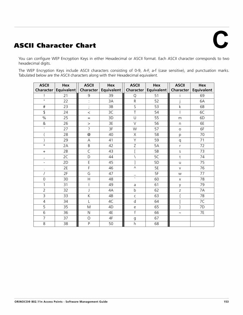
ORiNOCO® 802.11n Access Points - Software Management Guide
C
ASCII Character ChartYou can configure WEP Encryption Keys in either Hexadecimal or ASCII format. Each ASCII character corresponds to twohexadecimal digits.
The WEP Encryption Keys include ASCII characters consisting of 0-9, A-F, a-f (case sensitive), and punctuation marks.Tabulated below are the ASCII characters along with their Hexadecimal equivalent.
ASCII Character
Hex Equivalent
ASCII Character
Hex Equivalent
ASCII Character
Hex Equivalent
ASCII Character
Hex Equivalent
! 21 9 39 Q 51 i 69" 22 : 3A R 52 j 6A# 23 ; 3B S 53 k 6B$ 24 < 3C T 54 l 6C% 25 = 3D U 55 m 6D& 26 > 3E V 56 n 6E' 27 ? 3F W 57 o 6F( 28 @ 40 X 58 p 70) 29 A 41 Y 59 q 71* 2A B 42 Z 5A r 72+ 2B C 43 [ 5B s 73, 2C D 44 \ 5C t 74- 2D E 45 ] 5D u 75. 2E F 46 ^ 5E v 76/ 2F G 47 _ 5F w 770 30 H 48 ` 60 x 781 31 I 49 a 61 y 792 32 J 4A b 62 z 7A3 33 K 4B c 63 { 7B4 34 L 4C d 64 | 7C5 35 M 4D e 65 } 7D6 36 N 4E f 66 ~ 7E7 37 O 4F g 678 38 P 50 h 68
153

ORiNOCO® 802.11n Access Points - Software Management Guide
D
Frequently Asked Questions (FAQs)Link Integrity
Rogue Scan
This chapter covers the Frequently Asked Questions (FAQs) on the following topics:
• Link Integrity• Rogue Scan•• RADIUS VLAN•
Q. What will happen to a WDS link if the wireless interface (radio) goes down due to link integrity?
WDS link will remain unaffected, if the wireless interface goes down due to link integrity. Let’s say, you have 6 VAPs and 2 WDS links within the same wireless interface. If the connectivity to the server nodes (listed in the link integrity server configuration table) is lost, then all the 6 VAPs will go down but the WDS link is not affected.
Q. What are the messages generated in Event Logs and Syslog, while the radio is down/up due to the link integrity?
“Wireless Interface is down due to Link non availability” is the message generated, once the interface is down and “Wireless Interface is up due to Link availability” is the message generated when the interface is up and server nodes are reachable. Check Event Log and SysLog for the messages generated.
Q. Does the Rogue Scan feature on AP device detect non Wi-Fi interferences?
No, Rogue Scan feature on the AP device, detects only the sources of Wi-Fi interference.
Q. What is the maximum number of entries supported in the Rogue Scan results page?
For Current channel scan : 32 entries for all device types detected (10 entries for each device type) For All channel scan : 512 entries for all device types detected (100 entries for each device type)
: All the interface (radio) 2 parameters discussed in this chapter are applicable only to a dual-radiodevice.
154

Frequently Asked Questions (FAQs)
Q. Can I perform the background Rogue Scan on both the radios (where, radio 1 = 5 GHz and radio 2 = 2.4 GHz) at the same time?
Yes. You can perform the Rogue Scan on both the wireless interfaces (radios) at the same time.
Q. Does Rogue Scan apply on a WDS enabled radio?
Yes. Rogue Scan can be applied on a WDS enabled radio.
Q. Does Rogue Scan apply on the adjacent channels, if it is set to Current Channel Scan?
No. Rogue Scan is not applied on the adjacent channels, if it is set to Current Channel Scan.
Q. Where I can find the Rogue Scan results?
In the Web (HTTP) Interface, navigate to Monitor -> Rogue Scan -> Interface.
Q. How does the Rogue Scan feature on AP device, detect the Wi-Fi interferences?
i) For AP Devices: AP Devices are detected based on beacons, which has IBSS field set to 0ii) For STA Devices: STAs (Stations) are detected based on data packets which has TO DS bit=1.
: All probe request packets are considered as STAs.
iii) For WDS Devices: WDS Devices are detected based on data packets which has 4 address format (with 2 MAC address in the header).iv) For ADHOC Devices: ADHOC Devices are detected based on beacons, which has IBSS field set to 1.
Q. If the radio is configured in 5GHz and Rogue Scan is set to All Channel Scan, then does the Rogue Scan feature on the AP device scan a 2.4GHz channel?
• For AP-800/AP-8000: Yes. Rogue Scan is applicable on both 2.4 GHz and 5GHz channels in All Channel scan mode, irrespective of the frequency band configured on the radio.
• For AP-8100: No. Rogue Scan feature will only scan 5GHz channels on radio 1 and 2.4 GHz channels on radio 2.
Q. How to enable Rogue Scan on the AP device?
Navigate to Configuration -> Wireless Interface -> Properties -> Rogue Scan Status. Select “Current Channel Scan” or “All Channel Scan”
ORiNOCO® 802.11n Access Points - Software Management Guide 155

Frequently Asked Questions (FAQs)
Wireless Distribution Systems (WDS)
Q. By using AP-8000 / AP-8100, can I form the WDS link on both the radios at the same time?
Yes. You can form a WDS link on both the radios at the same time by configuring a VAP type in WDS mode (WDS-END-A/END-B), on both the radios. But we recommend keeping both the radios in different operational modes.
Q. How many WDS links does the AP device support?
The AP device supports a maximum of 6 WDS downlinks (with directly connected nodes) and minimum of 2 hops in a tree type topology.
Q. How to make sure that the WDS link is formed successfully and check the statistics?
To make sure that the WDS link is formed successfully, navigate to Monitor -> Station Statistics. Check the detailed statistics of entries with the VAP type set to “WDS”.
Q. Does WDS depend on the management VLAN ID?
No. WDS is independent of the management VLAN ID. You can form a WDS link between two AP Devices with same or different Management VLAN ID.
Q. How different is WDS-11n mode from WDS-legacy mode, apart from data rate and throughput?
• In WDS-Legacy mode, management frames are not exchanged during the link establishment. Data is directly forwarded to the peer MAC address.
• This mode does not support QoS or frame aggregation.
• In WDS-11n mode, management frames are exchanged during the link establishment.
• This mode supports QoS, frame aggregation and 11n-MIMO technology.
Q. Can I configure the VAP enabled in WDS mode and VAP enabled in AP mode, on the same radio?
Yes. You can configure both the VAP types on same radio. Below is the set up that illustrates configuring both, VAP in WDS and VAP in AP modes on same radio. You need to create two VAPs on AP2, one for WDS and one for AP mode.
(WDS-ENDA) AP1 ---------- (WDS-ENDB) AP2 (AP VAP) 1st VAP 1st VAP 2nd VAP
A WDS link is established between AP1 VAP and AP2 VAPs.
ORiNOCO® 802.11n Access Points - Software Management Guide 156

Frequently Asked Questions (FAQs)
Q. What should I do if the WDS link is not getting established?
• Make sure the operational mode and frequency configured is same for both the devices
• Check whether the peer MAC address added is correct.
• Configure valid and same security settings and keys on both the devices.
• Both the devices should be within the vicinity.
• Check the VAP type configuration on both devices. (One should be WDS-END-A and the other should be WDS-END-B or both should be set to WDS-Legacy in case of a legacy WDS link)
Q. At what rate, is the multicast traffic transmitted from a VAP enabled in WDS mode?
Multicast traffic is transmitted at a unicast rate upto 300Mbps, over the WDS-11n link.
Q. How to establish a WDS link, by using both the radios simultaneously? (Applicable only for a dual-radio device)
Below setup illustrates how to establish a WDS link, by using both the radios.
Radio1 <- AP1 -> Radio2 (WDS-ENDA) / \ (WDS-ENDA) 1st VAP / \ 1st VAP / \ 5GHz link / \ 2.4GHz link / \(WDS-ENDB) AP2 AP3 (WDS-ENDB) 1st VAP 1st VAP
Here, based on the channel bandwidth supported, a 5GHz and a 2.4GHz WDS links are established on both Radio 1 and Radio 2 of AP1, simultaneously.
Q. Do I need to configure only the corresponding VAPs at both the radios, to establish a WDS link?
No, it is not necessary that you use only the corresponding VAPs to form a WDS link. For example, you can use VAP 1 at AP1 and VAP 8 at AP2, to establish a WDS link. Add the peer MAC address of VAP 8 in AP1 and add the peer MAC address of VAP 1 in AP2.
Q. Can I form a WDS link between an AP-400/7000 device and an AP-800/8000/8100 device?
Yes. You need to configure a 11a or 11g operational mode (WDS-Legacy mode) on the AP-800/8000/8100 device to establish a WDS link with AP-400/7000 device.
ORiNOCO® 802.11n Access Points - Software Management Guide 157

Frequently Asked Questions (FAQs)
Q. How to create 2 hop WDS link?
AP1 (WDS-ENDA) -------- (WDS-ENDB) AP2 (WDS-ENDA) -------- (WDS-ENDB) AP3 1st VAP 1st VAP 2nd VAP 1st VAP
You need to create two VAPs on AP2 and set both the VAPs in WDS mode.
Q. How to establish multiple WDS downlinks?
Below setup illustrates how to establish two WDS downlinks. Here, the first link is established between VAP 1 of AP1 and VAP 1 of AP2, second link is established between VAP 2 of AP1 and VAP 1 of AP3.
(WDS-ENDA) AP1 (WDS-ENDA) 1st VAP / \ 2nd VAP / \ / \(WDS-ENDB) AP2 AP3 (WDS-ENDB) 1st VAP 1st VAP
Q. What are the expected throughput values for WDS?
Tabulated below are the throughput values, considering that the WDS link is established with maximum data rate.
Q. What is the effect on WDS, if the link integrity is enabled and the Link Status is down?
If the link integrity is enabled and the Link Status is down, then AP device disables all the VAPs enabled in AP mode only but does not interrupt the traffic on ethernet and WDS link.
Q. Does WDS support Auto Channel Selection (ACS)?
No. WDS does not support Auto Channel Selection (ACS). You cannot enable the Auto Channel Selection (ACS), when a VAP is configured in WDS mode.
Q. Can I configure WDS on a DFS channel?
You can configure WDS on a DFS channel, but it is recommended not to use a DFS channel to establish a WDS link.
No. of Hops 20 MHz 40MHz
1st Hop 60 Mbps 130 Mbps
2nd Hop 30 Mbps 60 Mbps
3rd Hop 10 Mbps 25 Mbps
ORiNOCO® 802.11n Access Points - Software Management Guide 158
Frequently Asked Questions (FAQs)
RADIUS VLAN
Q. How is WDS related with STP?
STP is enabled automatically when you enable a VAP in WDS mode. STP feature helps in avoiding loops in a ring topology formed by a WDS link.
Q. Why VLAN assignment via RADIUS is needed?
VLAN assignment via RADIUS reduces the effort of AP device, in manually configuring VLAN to a specific user. By using this feature we can dynamically assign VLANs to wireless clients when the clients are authenticated with RADIUS server. Hence, each client can maintain its own VLAN network.
Q. What if “Tunnel-Private-Group-ID” is empty?
If the “Tunnel-Private-Group-ID” is empty, the native VLAN ID configured (if any) in the VAP is applied to the client.
Q. What is the behavior of RADIUS VLAN assignment, while sending Broadcast/Multicast traffic?
• The Broadcast/Multicast traffic being sent from an ethernet backhaul PC (associated to any VLAN or NO VLAN), reaches the wireless clients irrespective of the VLANs applied to them.
• The Broadcast/Multicast traffic being sent from the wireless client (say with VLAN ID = VLAN 100) reaches the other wireless client(s) (irrespective of the VLANs applied) and ethernet backhaul PC associated to same VLAN (that is 100) or NO VLAN (but not to the PC associated to other VLANs).
Q. How is management VLAN ID related to RADIUS VLAN assignment?
If the management VLAN ID is configured, the RADIUS server should also be in the same VLAN to receive the request packet re-directed by the AP device.
Q. How to make sure that the clients are assigned with a correct VLAN ID via RADIUS server?
Go to Monitor -> Station Statistics -> corresponding client and click the “show” tab, which details all the parameters including the VLAN ID assigned.
Q. What is the limited number of clients, getting assigned the VALN Id from RADIUS server?
There is no limitation on the number of clients, assigned the VLAN ID via a RADIUS server. As a standard, AP device supports upto 128 clients per radio.
ORiNOCO® 802.11n Access Points - Software Management Guide 159

Frequently Asked Questions (FAQs)
Packet Forwarding
Q. In what scenarios Packet Forwarding can be used?
Packet forwarding feature is useful for public wireless networks where the clients cannot communicate with each other but should be able to access internet. This feature can also be used to sniff all the packets by sending all the wireless packets to the configured gateway, for security reasons.
Q. Can I access an Access Point directly from my wireless client, if Packet Forwarding is enabled?
Yes. You can access an Access Point from your wireless client. The traffic destined to the MAC address of an Access point will not be forwarded to the gateway.
Q. What will happen to the downlink traffic?
All the traffic from AP Device to wireless clients (downlink) will follow the regular Path, it will not go through the configured gateway.
Q. What will happen if I configure uplink port in WDS mode and disable a WDS link?
If Uplink port is configured as WDS and later if that WDS link is disabled, then the uplink port should be re-set to AUTO.
Q. What is default mode of Packet forwarding feature and is it a re-bootable parameter?
Packet forwarding feature is disabled by default. Configured settings take effect immediately after committing the changes. Reboot is not required.
ORiNOCO® 802.11n Access Points - Software Management Guide 160

ORiNOCO® 802.11n Access Points - Software Management Guide
E
GlossaryA
Access point A wireless network transceiver or "base station" hub, often used toconnect a local area network to one or more wireless devices. An accesspoint (also called AP) can provide a communication link to a wired localarea network also.
ADHOC A ‘client’ setting for a wireless local area network that allows devicesconnected to the network to communicate with one another directly,independent of an access point or router.
Advanced Encryption Standard (AES) It is a symmetric-key encryption standard, containing three block ciphersAES-128, AES-192, AES-256. Each of these ciphers has a 128-bit blocksize, with key sizes of 128, 192 and 256 bits, respectively.
ARP The Address Resolution Protocol (ARP) is intended to find the MACaddress belonging to an IP address.
Authentication The process the unit uses to decide whether a wireless client is allowed toregister to an access point network or not. IEEE 802.11 specifies two formsof authentication: open system and shared key; WORP only supportsshared key because of security constraints.
Authentication Server “Shared Secret”
This is a kind of password shared between the unit and the RADIUSauthentication server. This password is used to encrypt important dataexchanged between the unit and the RADIUS server.
B
Basic Service Set (BSS) A wireless network with atleast one Access Point (either connected to awired network infrastructure or a wireless backhaul) and a set of wirelessdevices forms a Basic Service Set (BSS).
Boolean Operators Boolean operators define the relationships between words or groups ofwords.
– AND: Narrow search and retrieve records containing all of the words it separates.
– OR: Broaden search and retrieve records containing any of the words it separates. The | can be used instead of 'or' (e.g., 'mouse | mice | rat' is equivalent to 'mouse or mice or rat').
: Depending on how the Boolean Operator AND is used with the Keyword Field (KW), results may be slightly different.
BPDU Packets A spanning tree protocol (STP) message unit that describes the attributesof a switch port such as its MAC address, priority and cost to reach. BPDUsenable switches that participate in a spanning tree protocol to gatherinformation about each other.
161

Glossary
Bridge An interface connecting a local area network to another local areanetwork that uses the same protocol (for example, wireless, Ethernet ortoken ring). Wireless bridges are commonly used to link buildings incampuses.
Broadcast Broadcast traffic is a large series of broadcast packets (most often causedby wrong network configuration) that severely impact the networkperformance.
Broadband In data communications, a "broadband connection" is a connection witha high speed of data transfer, fast enough to support a video streaming.
Broadcast SSID (BSSID) BSSID refers to the MAC address of the wireless client within an AccessPoint (AP) coverage area.
C
Client IP Address Pool This a pool of IP addresses from which the unit can assign IP addresses toclients, which perform a DHCP Request.
Carrier Sense Multiple Access with Collision Avoidance (CSMA / CA)
It is a wireless network multiple access method in which:
• A carrier sensing scheme is used.
• A node wishing to transmit data has to first listen to the channel to determine whether or not another node is transmitting on the channel within the wireless range. If the channel is sensed "idle," then the node is permitted to begin the transmission process. If the channel is sensed as "busy," the node defers its transmission for a random period of time. Once the transmission process begins, it is still possible for the actual transmission of application data to not occur.
Contention Window (CW) Contention Window is a set of time slots, that helps in configuring therandom backoff timer value, that should be within the ContentionWindow range (i.e) from CWmin to CWmax, where CWmin variesbetween each of the queues. See Access Category
Every wireless client waits for this random backoff timer value set, toaccess the wireless medium. This avoids collision over the medium, givingan equal chance to every wireless station on the network to access themedium.
Cyclic Redundancy Check (CRC) A cyclic redundancy check (CRC) is an error-detecting code commonlyused in digital networks and storage devices to detect accidental changesto raw data. Blocks of data entering these systems get a short check valueattached, based on the remainder of a polynomial division of theircontents; on retrieval the calculation is repeated, and corrective action canbe taken against presumed data corruption if the check values do notmatch.
B
ORiNOCO® 802.11n Access Points - Software Management Guide 162

Glossary
D
Digital Subscriber Line (DSL) Digital subscriber line is a technology that provides internet access bytransmitting digital data over the wires of a local telephone network.
Domain Name Server (DNS) A domain name server is an Internet service that translates domain namesinto IP addresses. For example, www.ietf.org is translated into 4.17.168.6.
Downstream / Downlink Downstream means a data stream from the central part of the network tothe end user. Also, refer Upstream / Uplink.
Dual-Band Dual-band refers to a device's ability to function on two differentfrequency bands.
Dynamic Frequency Selection (DFS) DFS helps you select the operating frequency that does not interfere withthe RADAR signals, by continuously detecting the range of operatingfrequencies with a RADAR interference.
Dynamic Host Configuration Protocol(DHCP)
Dynamic Host Configuration Protocol (DHCP) is a method to dynamicallyassign IP addresses. If DHCP is enabled, the device or computer broadcastsa request that is answered by a DHCP Server.
Dynamic IP address An IP address assigned to a client, each time the client connects to thenetwork. The dynamic IP address is configured by the DHCP server andcan be different each time the client connects to the network.
E
Extensible Authentication Protocol (EAP)
EAP is an authentication framework providing the transport and usage ofkeying material and parameters generated by EAP methods. EAP is not awire protocol, instead it only defines the message formats. Each protocolthat uses EAP defines a way to encapsulate EAP messages within thatprotocol's messages.
Encryption Encryption is a means of coding data with a key before sending it across anetwork. The same key must be used to decode the information at thereceiver. This way, it prevents unauthorized access to the data that is sentacross the network.
Encryption Key An alphanumeric (letters and/or numbers) series that enables data to beencrypted and then decrypted, so it can be securely shared amongmembers of the same network.
WEP uses an encryption key that automatically encrypts outgoing wirelessdata. On the receiving side, the same encryption key enables thecomputer to automatically decrypt the information so it can be read.
G
Group A group is a logical collection of network parameters. For example, theSystem Group is composed of several parameters and tables giving systeminformation of the unit. All items for a group are grouped under one tabof the Web Interface and start with the same prefix for the command lineinterface.
ORiNOCO® 802.11n Access Points - Software Management Guide 163

Glossary
H
Hexadecimal A numeral system with a radix or base, of 16. It uses sixteen distinctsymbols, 0–9 to represent values zero to nine and A, B, C, D, E, F torepresent values ten to fifteen. Each hexadecimal digit represents fourbinary digits (bits).
HTTP Hypertext Transfer Protocol (HTTP) is the protocol to transport Web pages.When you access the Internet with your browser, the HTTP protocol isused for data transport (http://www.Tsunamiwireless.com). When youaccess the unit by using the Web Interface, HTTP is used to transport theinformation. HTTPS is the Secure Hypertext Transfer Protocol.
I
ICMP Internet Control Message Protocol (ICMP) is used by computers anddevices to report errors encountered during processing packets, and toperform other IP-layer functions, such as diagnostics (‘ping’).
L
LAN A Local Area Network (LAN) is a network of limited size to whichcomputers and devices can connect so that they can communicate witheach other.
License File A license file is used to enable certain features of the unit. The unit alreadyhas a license file when it is shipped. When more features becomeavailable, you can purchase a license file and download it to the unit toenable these additional features.
M
MAC Address A MAC (Media Access Control) address is a globally unique networkdevice address, which is hardware bound. It is used to identify a networkdevice in a LAN. A MAC address is represented by six two-digithexadecimal numbers (0 - 9 and A - F) separated by colons: for example00:02:2D:47:1F:71 and 00:D0:AB:00:01:AC.
Management Information Base (MIB) A Management Information Base (MIB) is a formal description of a set ofnetwork objects that can be managed with the Simple NetworkManagement Protocol (SNMP). A MIB can be loaded by a managementapplication so that it knows the unit specific objects.
MPDU Packets MPDU stands for MAC Protocol Data Unit. MPDUs are the fragmentedunits of MSDUs.
MSDU MSDU stands for MAC Service Data Unit. The MSDU is that unit of datathat is received from the LLC sub-layer, which lies above the MACsub-layer in a protocol stack.
Multicast A one-to-many communication or a delivery of a message or informationto a group of destination computers simultaneously in a singletransmission.
ORiNOCO® 802.11n Access Points - Software Management Guide 164

Glossary
N
NETBIOS It provides services related to the session layer of the OSI model allowingapplications on separate computers to communicate over a local areanetwork.
Network Address Translation Network Address Translation is a method by which IP addresses aremapped from one address realm to another, providing transparentrouting to end hosts.
Network Mask See Subnet Mask
O
Orthogonal Frequency Division Multiplexing (OFDM)
OFDM is a frequency-division multiplexing (FDM) scheme, a method ofencoding digital data on multiple carrier frequencies. A large number ofclosely spaced orthogonal sub-carrier signals are used to carry data. Thedata is divided into several parallel data streams or channels, one for eachsub-carrier, maintaining total data rates similar to conventionalsingle-carrier modulation schemes in the same bandwidth.
P
Pass Phrase A text string used for WPA security on a Wi-Fi wireless network. Apassphrase may contain up to 8 to 64 alphanumeric characters, includingspaces and other special characters.
Ping Ping is a basic Internet program that lets you verify if a particular computeror device with a certain IP address is reachable. If the computer or devicereceives the ping packet, it responds to it, which gives the ping programthe opportunity to display the round-trip time.
Port Number TCP and UDP provide an address mechanism, the port number, foridentifying different applications communicating from the same IPaddress. Thus an active Web browser and an independently active mailprogram operating from the same IP location would typically use differentport numbers so that packets are correctly delivered to specificapplications.
Probe Request A wireless client sends a probe request frame when it needs to obtaininformation from another wireless client or an access point. For example,a radio NIC would send a probe request to determine which access pointsare within range.
Probe Response A wireless client or an access point will respond to the probe request witha probe response frame, containing capability information, supporteddata rates, etc.
ORiNOCO® 802.11n Access Points - Software Management Guide 165

Glossary
Q
QoS The Quality of Service (QoS) feature is based on the 802.16 standard anddefines the classes, service flows, and packet identification rules forspecific types of traffic. The main priority of QoS is to guarantee a reliableand adequate transmission quality for all types of traffic under conditionsof high congestion and bandwidth over-subscription.
R
RADIUS Server Remote Authentication Dial In User Service (RADIUS) is a client/servernetworking protocol that runs in the application layer, by using UDP astransport and provides centralized Authentication, Authorization, andAccounting (AAA) management for computers to connect and use anetwork service. The RADIUS server is a background process that servesthe following three functions:
• To authenticate users or devices before granting them access to a network
• To authorize those users or devices for certain network services
• To account the users for usage of the provided services.
Rogue Devices Rogue devices include Rogue 802.11n AP devices and Rogue wirelessdevices (AP/STA/WDS/ADHOC), that are not authorized and secure.
RTS Frame A node wishing to send data initiates the process by sending aRequest-to-Send (RTS) frame.
RIP Routing Information Protocol (RIP) is used between routers to updaterouting information so that a router automatically ‘knows’ which port touse for a certain destination IP address.
Router Routers forward packets from one network to another based on routinginformation. A router uses a dynamic routing protocol like RIP or staticroutes to base its forwarding decision on.
S
ScanTool A computer program that can be used to retrieve or set the IP address of alocally connected unit.
Simple Network Management Protocol (SNMP)
A protocol used for the communication between a network managementapplication and the devices it is managing. The network managementapplication is called the SNMP manager and the devices it manages willhave SNMP agents. Not only the unit but also almost every network devicecontains a SNMP agent. The manageable objects of a device are arrangedin a Management Information Base, also called MIB. The Simple NetworkManagement Protocol (SNMP) allows managers and agents tocommunicate for accessing these objects.
Single-Band Single-band refers to a device's ability to function only on one frequencyband.
ORiNOCO® 802.11n Access Points - Software Management Guide 166

Glossary
Spanning Tree Protocol (STP) The Spanning Tree Protocol (STP) can be used to create redundantnetworks (“hot standby”) and to prevent loops. If enabled, spanning treeprevents loops by disabling redundant links. If a link fails, it canautomatically enable a backup link.
SSH A security protocol for logging into a remote server. SSH provides anencrypted session for transferring files and executing server programs.
SSL Secure Socket Layer is a commonly used encryption scheme used by manyonline retail and banking sites to protect the financial integrity oftransactions.
SSID A Service Set Identifier (also referred to as a network name) is a commonname that identifies a wireless network. The identifier is attached to thewireless local area network (WLAN) and acts as an identifier when a devicetries to connect to the system. A device will not be permitted to join thenetwork unless it can provide the unique SSID. An SSID can be broadcastby the network router, allowing devices to detect it as an availablenetwork. An SSID does not supply security to the network
STP Frames The data frames exchanged in an STP network topology are called as theSTP Frames, BPDU frames being one of them.
Subnet Mask A subnet mask is a bit mask that defines which part of an IP address isused for the network part and which part for a host (computer) number.A subnet mask is like an IP address represented by four numbers in therange 0 - 255 separated by dots. When the IP address 172.17.23.14 has asubnet mask of 255.255.255.0, the network part is 172.17.23 and thehost number is 14. See also IP address.
Syslog Server Syslog Server receives, logs, displays, and forwards syslog messages fromnetwork devices like routers.
T
Tagged Frames When a frame enters the VLAN-aware area of the network, a tag is addedto represent the VLAN membership of the frame's port or theport/protocol combination. These are called Tagged Frames.
TCP / IP The TCP/IP internet-suite protocol describes a set of general designguidelines and implementations of specific networking protocols toenable computers to communicate over a network. TCP/IP providesend-to-end connectivity specifying how data should be formatted,addressed, transmitted, routed and received at the destination.
Telnet Telnet is a network protocol used on the Internet or local area networks toaccess the command-line interface, on a remote host. Most networkequipment and operating systems with a TCP/IP stack support a Telnetservice for remote configuration.
Topology Topology is the physical layout of network components (cable, wirelessclients, gateways, hubs, and so on).
S
ORiNOCO® 802.11n Access Points - Software Management Guide 167

Glossary
Trap A trap is used within SNMP to report an unexpected or unallowablecondition.
Trivial File Transfer Protocol (TFTP) Trivial File Transfer Protocol (TFTP) is a lightweight protocol for transferringfiles that is like a simple form of File Transfer Protocol (FTP). A TFTP client isimplemented on the unit. By using the upload and download commands,the unit can copy a file to or from a TFTP server. TFTP server software isprovided on the product CD-ROM.
U
Unicast Unicast transmission is the sending of messages to a single networkdestination identified by a unique address.
Untagged Frames Untagged frame is a frame which not added with a tag or has no VLAN Idassociated to it.
Upload Uploading a file means copying a file from a network device to a remoteserver. In case of the unit, uploading means transferring a file from theunit to a TFTP server. See also download.
Upstream / Uplink Upstream means a data stream from the end users to the central part ofthe network. See also Downstream / Downlink.
V
VLAN The Virtual Local Area Network (VLAN) feature helps in logical grouping ofnetwork host on different physical LAN segments, which cancommunicate with each other as if they are all on the same physical LANsegment.
W
WEP The Wired Equivalent Privacy (WEP) algorithm is the standard encryptionmethod used to protect wireless communication from eavesdropping.
Wireless Client / Station (STA) A computer or program, connected to an access point network, that canaccess the wireless network, download files for manipulation, runapplications, or request application-based services from a file server iscalled a wireless client or a wireless station (STA).
WLAN A flexible data communication system implemented as an extension to oras an alternative for a wired LAN within a building or campus. By usingelectromagnetic waves, WLANs transmit and receive data over the air,minimizing the need for wired connections.
WPA Wi-Fi Protected Access is a Wi-Fi security standard that provides a highlevel of wireless network security. It uses data encryption through theTemporal Key Integrity Protocol (TKIP). TKIP scrambles the keys andensures that the keys haven't been tampered with. User authentication isperformed through the Extensible Authentication Protocol (EAP), toensure that only authorized network users can access the network.
T
ORiNOCO® 802.11n Access Points - Software Management Guide 168

ORiNOCO® 802.11n Access Points - Software Management Guide
F
AbbreviationsA
AP Access Point
ACL Access Control List
ACS Automatic Channel Selection
ACM Admission Control Mandatory
AES Advanced Encryption Standard
AMPDU Aggregated MAC Protocol Data Unit
ARP Address Resolution Protocol
ATPC Adaptive Transmit Power Control
AIFS Arbitration Inter-Frame Spacing
ASCII American Standard Code for Information Interchange
B
BBS Bulletin Board Systems
BPDU Bridge Protocol Data Units
BSS Basic Service Set
BSSID Basic Service Set Identifier
C
CLI Command Line Interface
CW Contention Window
CRC Cyclic Redundancy Check
D
DES Data Encryption Standard
DFS Dynamic Frequency Selection
DHCP Dynamic Host Configuration Protocol
DNS Domain Name System
DOS Disk Operating System
DSL Digital Subscriber Line
DSCP Differentiated Services Code Point
169

Abbreviations
DTIM Delivery Traffic Indication Map
E
EAP Extensible Authentication Protocol
EDCA Enhanced Distributed Channel Access
G
Gbps Gigabit Per Second
GPL General Public License
GPS Global Positioning System
H
HTTP HyperText Transfer Protocol
HTTPS HyperText Transfer Protocol Secure
I
IANA Internet Assigned Numbers Authority (IANA)
IBSS Independent Basic Service Set
IEEE Institute of Electrical and Electronics Engineers
IP Internet Protocol
ICMP Internet Control Message Protocol
IGMP Internet Group Management Protocol
ISP Internet Service Provider
L
LAN Local Area Network
LGPL Lesser General Public License
LSP Layered Service Providers
M
MAN Metropolitan Area Networks
Mbps Megabits Per Second
MD5 Message-Digest algorithm
MIB Management Information Base
MIMO Multiple-input and multiple-output
MIR Maximum Information Rate
MPDU MAC (Media Access Control) Protocol Data Units
ORiNOCO® 802.11n Access Points - Software Management Guide 170

Abbreviations
MSDU MAC (Media Access Control) Service Data Units
MTU Maximum Transmission Unit
N
NAS Network Attached Storage
NAT Network Address Translation
NBD Next Business Date
NETBIOS Network Basic Input / Output System
NMS Network Management System
NIC Network Interface Card
NoACK No Acknowledgement
O
OFDM Orthogonal Frequency Division Multiplexing
P
PoE Power Over Ethernet
POST Power On Self Test
PSDU Protocol Service Data Unit
PSK Pre-Shared-Key
PVES ProximVision ES
R
RADIUS Remote Authentication Dial In User Service
RAS Remote Access Services
RF Radio Frequency
RIP Routing Information Protocol
RMA Return Material Authorization
RSSI Received Signal Strength Indicator
RTS Request-To-Send
S
SAP Service Advertising Protocol
SHA Secure Hash Algorithm
SKU Stock Keeping Unit
SNMP Simple Network Management Protocol
ORiNOCO® 802.11n Access Points - Software Management Guide 171

Abbreviations
SNTP Simple Network Time Protocol
SSH Secure Shell
SSL Secure Socket Layer
STA Wireless client / Wireless Station
STP Spanning Tree Protocol
SSLv3 Secure Socket Layer - Version 3
SSID Service Set Identifier
T
TBC Text Based Configuration
TCP Transmission Control Protocol
TFTP Trivial File Transfer Protocol
TKIP Temporal Key Integrity Protocol
TPC Transmit Power Control
TPID Tag Protocol Identifier
TSLF Time Since Last Frame
TxOP Transmission Opportunity
U
UDP User Datagram Protocol
V
VAP Virtual Access Point
VLAN Virtual Local Area Network
VoIP Voice Over Internet Protocol
W
WAN Wide Area Networks
WDS Wireless Distribution System
WEP Wired Equivalent Privacy
WLAN Wireless Local Area Networks
WME / WMM Wireless Multimedia Extensions / Wireless Multi Media
WPA Wi-Fi Protected Access
X
XML Extensible Markup Language
ORiNOCO® 802.11n Access Points - Software Management Guide 172
ORiNOCO® 802.11n Access Points - Software Management Guide
G
Statement of WarrantyWarranty CoverageProxim Wireless Corporation warrants that its products are manufactured solely from new parts, conform substantially tospecifications, and will be free of defects in material and workmanship for a Warranty Period of 1 year from the date ofpurchase.
Repair or ReplacementWhen Proxim determines that a returned product does not meet the warranted criteria during the warranty period, Proxim atits option, will either: (a) repair the defective product; (b) replace the defective product with a new or refurbished productthat is at least equivalent to the original; or (c) refund the price paid for the defective product. Generally, products arerepaired or replaced within thirty (30) business days of receipt of the product at a Proxim Logistical/Repair Center. Thewarranty period for repaired or replacement products is ninety (90) days or the remainder of the original warranty period,whichever is longer. These three alternatives constitute the customer’s sole and exclusive remedy and Proxim’s sole andexclusive liability under warranty provisions.
Limitations of WarrantyProxim’s warranties do not apply to any product (hardware or software) which has (a) been subjected to abuse, misuse,neglect, accident, or mishandling, (b) been opened, repaired, modified, or altered by anyone other than Proxim, (c) been usedfor or subjected to applications, environments, or physical or electrical stress or conditions other than as intended andrecommended by Proxim, (d) been improperly stored, transported, installed, or used, or (e) had its serial number or otheridentification markings altered or removed.
Buyers can contact Proxim Wireless Customer Service Center either by telephone or via web. Support and repair of productsthat are out of warranty will be subject to a fee. Contact information is shown below. Additional support information can befound at Proxim Wireless’s web site at http://support.proxim.com.
Contact technical support via telephone as follows:
USA and Canada Customers
Phone: +1-408-383-7700; +1-866-674-6626
Business Hours: 24x7 live response. Tier 3 support: 8 a.m. to 5 p.m. M-F PDT (UTC/GMT -7 hrs)
International Customers
Phone: +1-408-383-7700; 0800-916475 (France); 8-800-100-9485 (Russia)
Business Hours: 24x7 live response. Tier 3 support: 8 a.m. to 5 p.m. M-F PDT (UTC/GMT -7 hrs)
General ProceduresWhen contacting the Customer Service for support, Buyer should be prepared to provide the product description and serialnumber and a description of the problem. The serial number should be on the product.
In the event the Customer Service Center determines that the problem can be corrected with a software update, Buyer mightbe instructed to download the update from Proxim Wireless’s web site or, if that’s not possible, the update will be sent toBuyer. In the event the Customer Service Center instructs Buyer to return the product to Proxim Wireless for repair orreplacement, the Customer Service Center will provide Buyer a Return Material Authorization (“RMA”) number and shippinginstructions. Buyer must return the defective product to Proxim Wireless, properly packaged to prevent damage, shippingprepaid, with the RMA number prominently displayed on the outside of the container.
173

Statement of Warranty
Calls to the Customer Service Center for reasons other than product failure will not be accepted unless Buyer has purchased aProxim Wireless Service Contract or the call is made within the warranty period. After the warranty period, Technical Supportis fee based (detailed in Technical Services and Support).
If Proxim Wireless reasonably determines that a returned product is not defective or is not covered by the terms of thisWarranty, Buyer shall be charged a service charge and return shipping charges.
Other Information
Search KnowledgebaseProxim Wireless stores all resolved problems in a solution database at the following URL: http://support.proxim.com.
Ask a Question or Open an IssueSubmit a question or open an issue to Proxim Wireless technical support staff at the following URL: http://support.proxim.com/cgi-bin/proxim.cfg/php/enduser/ask.php.
ORiNOCO® 802.11n Access Points - Software Management Guide 174

ORiNOCO® 802.11n Access Points - Software Management Guide
H
Technical Services and SupportObtaining Technical Service and SupportIf you are having trouble using the Proxim product, please read this manual and the additional documentation provided withyour product. If you require additional support to resolve your issue, please be ready to provide the following informationbefore you contact Proxim’s Technical Services team:
• Product information
– Part number and serial number of the suspected faulty device
• Trouble/error information
– Trouble/symptom being experienced
– Activities completed to confirm fault
– Network information (What kind of network are you using?)
– Circumstances that preceded or led up to the error
– Message or alarms viewed
– Steps taken to reproduce the problem
• ServPak information (if a Servpak customer):
– ServPak account number
• Registration information
– If the product is not registered, date and location where you purchased the product.
: Technical Support is free for the warranty period from the date of purchase.
Support Options
Proxim eService Web Site SupportThe Proxim eService Web site is available 7x24x365 at http://support.proxim.com. On the Proxim eService Web Site, you canaccess the following services:
• Product Download Page: Provides quick links to product firmware, software, and documentation downloads.
• Proxim TV Links: A link to helpful video tutorials.
• Knowledgebase: A solution database of all the resolved problems. You can search by product, category, keywords,or phrases.
• Live Chat: Chat with a support technician on-line or request to call back at a later time.\
• Open Ticket / Ask Question: Submit a question to our technical support staff who will reply to you by email.
• My Account / Tickets: Login to check the status of your questions, modify your answer update notifications, updateyour personal profile, or access restricted information and features.
• Provide Feedback: Submit a suggestion, complaint, or other feedback about the support site.
175

Technical Services and Support
Telephone SupportContact technical support via telephone as follows:
USA and Canada Customers
Phone: +1-408-383-7700; +1-866-674-6626
Business Hours: 24x7 live response. Tier 3 support: 8 a.m. to 5 p.m. M-F PDT (UTC/GMT -7 hrs)
International Customers
Phone: +1-408-383-7700; 0800-916475 (France); 8-800-100-9485 (Russia)
Business Hours: 24x7 live response. Tier 3 support: 8 a.m. to 5 p.m. M-F PDT (UTC/GMT -7 hrs)
ServPak SupportTo provide even greater investment protection, Proxim Wireless offers a cost-effective support program called ServPak.ServPak is a program of enhanced service support options that can be purchased as a bundle or individually, tailored to meetyour specific needs. Whether your requirement is round the clock technical support or advance replacement service, we areconfident that the level of support provided in every service in our portfolio will exceed your expectations.
• Advanced Replacement of Hardware: Can you afford to be down in the event of a hardware failure? Our guaranteed turnaround time for return to factory repair is 30 days or less. Those customers who purchase this service are entitled to advance replacement of refurbished or new hardware guaranteed to be shipped out by the Next Business Day. Hardware is shipped Monday – Friday, 8:00 AM – 2:00 PM (PST).
• Extended Warranty: Extend the life of your networking investment by adding 1, 2, or 3 years to your products standard warranty. This service coverage provides unlimited repair of your Proxim hardware for the life of the service contract. The cost of an extended warranty is far less than the cost of a repair providing a sensible return on your investment.
• 7x24x365 Technical Support: This service provides unlimited, direct access to Proxim’s world-class Tier 3 technical support engineers 24 hours a day, 7 days a week, 365 days a year including Holidays. Customers who purchase this service can rest assured that their call for technical assistance will be answered and a case opened immediately to document the problem, troubleshoot, identify the solution and resolve the incident in a timely manner or refer to an escalation manager for closure.
• 8x5 Technical Support: This service provides unlimited, direct access to Proxim's world-class technical support 8 hours a day, 5 days a week from 8:00AM - 5:00PM (PDT). Typically, technical support is provided for free for the entire time the product is covered by a Proxim warranty. Beyond this period, technical support is available at cost on a per incident basis. With the 8x5 Technical Support service, technical support will be available for the duration of the ServPak contract at no additional costs.
• Software Maintenance: It's important to maintain and enhance security and performance of wireless equipment and Proxim makes this easy by providing a Software Maintenance program that enables customers to access new features and functionality, rich software upgrades and updates. Customers will also have full access to Proxim's vast knowledgebase of technical bulletins, white papers and troubleshooting documents.
• Priority Queuing Phone Support: This service provides customers with a one hour response time for technical phone support. There is no waiting in line for those urgent calls for technical support.
Packaged Services• 24 x 7 Enhanced ServPak
– 24 x7 Technical Support
– Software Maintenance
– Advanced Hardware Replacement
– Extends Warranty*
– Knowledge Base Access
ORiNOCO® 802.11n Access Points - Software Management Guide 176

Technical Services and Support
– Priority Queuing * if units are out of standard warranty
• 8 x 5 Enhanced ServPak
– 8 x 5 Technical Support
– Software Maintenance
– Advanced Hardware Replacement
– Extends Warranty*
– Knowledge Base Access
– Priority Queuing * if units are out of standard warranty
ServPak Standalone Services• Extended Warranty ServPak
• Advance Hardware Replacement ServPak
Proxim Warranty vs. ServPak Service
- Not a feature service option
To purchase ServPak support services, please contact your authorized Proxim distributor. To receive more information or forquestions on any of the available ServPak support options, please visit our website athttp://www.proxim.com/support/servpak, call Proxim Support (For telephone numbers, see Telephone Support) or send anemail to [email protected].
Technical Support Policy
Technical Support for Current Products during Warranty PeriodAll Customers are entitled to free technical support for the Proxim products they purchase from Proxim’s authorized resellersor distributors. Technical Support is defined as communication via the Proxim Support website (http://support.proxim.com)and/or via telephone. This technical support will be provided for free for the entire time the product is covered by a Proximwarranty. The term of Proxim’s warranty is determined according to the agreement under which the product was sold andgenerally varies from 3 months to 2 years depending on the product. If a Customer disagrees with Proxim’s determination ofwarranty duration, a request for review supported by a copy of all product purchase documentation may be submitted.
Service Features ServPak Warranty
Expert Technical Support Technical Support, Configurations, Troubleshooting
Duration of Product Warranty. 8X5 Normal Business Hrs
Priority Queuing Available -
Knowledge Base Access Available Available
Software Upgrades Available -
Advance Replacement Service 8x5xNBD -
ORiNOCO® 802.11n Access Points - Software Management Guide 177

Technical Services and Support
Technical Support for Current Products after Warranty PeriodAfter the warranty period, technical support on products then being sold by Proxim will be based upon one of the followingthree options Customers can choose:
• Customers can choose to purchase one of Proxim’s ServPak extended warranty and enhanced support packages for the product
• Customers can choose to purchase one-time per-incident technical support for the product for a fee
• Customers can choose to call the reseller or distributor who sold them the product for technical support
Tech Support on Discontinued ProductsTechnical Support on some products that Proxim has declared as EOL (End of Life) or otherwise is no longer selling is availablebased upon one of the following three options Customers can choose:
• For some discontinued products, Customers can choose to purchase one of Proxim’s EOL ServPak support packages for the product
– No EOL ServPak support package will be available for any product discontinued more than 5 years ago
– No EOL ServPak support package is available for certain discontinued products
• Customers can choose to purchase one-time per-incident technical support for the product on a per hour basis at a rate of $125 an hour (4 hours minimum payable in advance by major credit card). This fee is payable in addition to any RMA fee that may be charged to subsequently repair the product.
• Customers can choose to call the reseller or distributor who sold them the product for technical support
All Proxim technical support for discontinued products, whether through an EOL ServPak package or otherwise, is providedon a “best effort” basis and is subject to the continued availability of necessary components, equipment, and other technicalresources.
Note that Proxim is unable to support or warrant any equipment that has been modified, whether this modification isphysical, or if third-party software codes have been loaded onto the product.
ORiNOCO® 802.11n Access Points - Software Management Guide 178