SOFTWARE For OM-CP Series IQ/OQ/PQ Guidelines · It is the responsibility of the individual(s)...
96
® , ENGINEERING INC. omega.com 800-DAS-IEEE (800-327-4333) © COPYRIGHT 2010 OMEGA ENGINEERING, INC. omega.com e-mail: [email protected] For latest product manuals: omegamanual.info SECURE DATA RECORDER SOFTWARE For OM-CP SERIES DATA LOGGERS IQ/OQ/PQ Guidelines Shop online at User’s Guide Secure Data Recorder Software for use with OM-CP Series Data Loggers
Transcript of SOFTWARE For OM-CP Series IQ/OQ/PQ Guidelines · It is the responsibility of the individual(s)...

®,ENGINEERING INC.
omega.com800-DAS-IEEE (800-327-4333)
© COPYRIGHT 2010 OMEGA ENGINEERING, INC.
omega.com e-mail: [email protected]
For latest product manuals:omegamanual.info
SECURE DATA RECORDERSOFTWARE For OM-CP SERIES
DATA LOGGERSIQ/OQ/PQ Guidelines
Shop online at
User’s Guide
Secure Data Recorder Softwarefor use with OM-CP Series Data Loggers

Servicing North America:U.S.A.: Omega Engineering, Inc., One Omega Drive, P.O. Box 4047ISO 9001 Certified Stamford, CT 06907-0047 USA
Toll Free: 1-800-826-6342 TEL: (203) 359-1660FAX: (203) 359-7700 e-mail: [email protected]
Canada: 976 BergarLaval (Quebec), H7L 5A1 CanadaToll-Free: 1-800-826-6342 TEL: (514) 856-6928FAX: (514) 856-6886 e-mail: [email protected]
For immediate technical or application assistance:U.S.A. and Canada: Sales Service: 1-800-826-6342/1-800-TC-OMEGA®
Customer Service: 1-800-622-2378/1-800-622-BEST®
Engineering Service: 1-800-872-9436/1-800-USA-WHEN®
Mexico/ En Español: 001 (203) 359-7803 FAX: 001 (203) 359-7807Latin America: [email protected] e-mail: [email protected]
Servicing Europe:Benelux: Managed by the United Kingdom Office
Toll-Free: 0800 099 3344 TEL: +31 20 347 21 21FAX: +31 20 643 46 43 e-mail: [email protected]
Czech Republic: Frystatska 184733 01 Karviná, Czech RepublicToll-Free: 0800-1-66342 TEL: +420-59-6311899FAX: +420-59-6311114 e-mail: [email protected]
France: Managed by the United Kingdom OfficeToll-Free: 0800 466 342 TEL: +33 (0) 161 37 29 00FAX: +33 (0) 130 57 54 27 e-mail: [email protected]
Germany/Austria: Daimlerstrasse 26D-75392 Deckenpfronn, GermanyToll-Free: 0800 6397678 TEL: +49 (0) 7056 9398-0FAX: +49 (0) 7056 9398-29 e-mail: [email protected]
United Kingdom: OMEGA Engineering Ltd.ISO 9001 Certified One Omega Drive, River Bend Technology Centre, Northbank
Irlam, Manchester M44 5BD United KingdomToll-Free: 0800-488-488 TEL: +44 (0) 161 777-6611FAX: +44 (0) 161 777-6622 e-mail: [email protected]
OMEGAnet® Online Service Internet e-mailomega.com [email protected]
It is the policy of OMEGA Engineering, Inc. to comply with all worldwide safety and EMC/EMIregulations that apply. OMEGA is constantly pursuing certification of its products to the European NewApproach Directives. OMEGA will add the CE mark to every appropriate device upon certification.The information contained in this document is believed to be correct, but OMEGA accepts no liability for anyerrors it contains, and reserves the right to alter specifications without notice.WARNING: These products are not designed for use in, and should not be used for, human applications.

Omega IQ/OQ/PQ Guidelines Manual for Secure Software
Page 2 of 93 DOC-0107002-00 Rev 1.01
DOCUMENT HISTORY
DESCRIPTION IDENTIFICATION
Document Number Description
DOC-0107002-00 IQ/OQ/PQ Guidelines Manual for Omega Secure Data Recorder Software V3.00.70
DOCUMENT REVISIONS
Date Issued Version Modifications by: Approved:
May 2, 2008 Release 1.00 Andrew Glum Tabitha Lemelin
June 10, 2008 Release 1.01 Tabitha Lemelin Tabitha Lemelin
DESCRIPTION OF REVISIONS
Version Change Description
Release 1.00 Original Document (Software Version 3.00.70)
Release 1.01 Updated Format and Grammatical Changes
RELEASE SIGNATURES
Released: Norman Carlson
Authors Tabitha Lemelin and Andrew Glum Document Number: DOC-0107002-00 Document Revision: 1.01 Date Revised: June 10, 2008 Release Status: Released
Confidential: This document is property of Omega and may not – in full or in part – be passed on, reproduced, or published without the written permission of Omega.

Omega IQ/OQ/PQ Guidelines Manual for Secure Software
Page 3 of 93 DOC-0107002-00 Rev 1.01
TABLE OF CONTENTS
1 INSTALLATION QUALIFICATION (IQ) .......................................................................... 5 1.1 PURPOSE ........................................................................................................... 5 1.2 RESPONSIBILITIES .............................................................................................. 5
1.2.1 OMEGA ...................................................................................................... 5 1.2.2 END USER ................................................................................................. 5
1.3 SCOPE ............................................................................................................... 5 1.4 PROCEDURE VARIATION ...................................................................................... 5 1.5 OMEGA EQUIPMENT ............................................................................................ 6
1.5.1 OMEGA PC INTERFACE SYSTEM .................................................................... 6 1.5.2 SYSTEM REQUIREMENTS .............................................................................. 6 1.5.3 OMEGA DATA LOGGERS ............................................................................... 8
1.6 INSTALLATION QUALIFICATION PROCEDURE .......................................................... 9 1.6.1 SITE PREPARATION ..................................................................................... 9 1.6.2 UNPACKING THE OMEGA SYSTEM ................................................................. 9 1.6.3 OMEGA SECURE DATA LOGGER SOFTWARE INSTALLATION ............................. 10 1.6.4 INTERFACE DRIVER INSTALLATION ............................................................. 14 1.6.5 OMEGA DATA LOGGER SECURE SYSTEM PC CONNECTION .............................. 15 1.6.6 LAUNCHING THE OMEGA SECURE SOFTWARE ............................................... 16 1.6.7 COMMUNICATIONS PROCEDURE ................................................................. 18 1.6.8 SETUP VERIFICATION RECORD ................................................................... 19
1.7 SYSTEM ACCEPTANCE ........................................................................................ 20 2 OPERATIONAL QUALIFICATION (OQ) ........................................................................ 21
2.1 PURPOSE ......................................................................................................... 21 2.2 RESPONSIBILITIES ............................................................................................ 21
2.2.1 OMEGA .................................................................................................... 21 2.2.2 END USER ............................................................................................... 21
2.3 SCOPE ............................................................................................................. 21 2.4 DATA LOGGER HANDLING AND MAINTENANCE ...................................................... 22
2.4.1 DATA LOGGER HANDLING .......................................................................... 22 2.4.2 BATTERIES .............................................................................................. 22
2.5 CREATING ADMINISTRATIVE USER ...................................................................... 23 2.6 SECURITY SETTINGS ......................................................................................... 25
2.6.1 SECURITY SETTINGS SETUP ....................................................................... 25 2.6.2 SECURITY SETTINGS VERIFICATION ............................................................ 29
2.7 OMEGA SECURE SYSTEM PREFERENCES ............................................................... 36 2.7.1 OMEGA SECURE SYSTEM PREFERENCES VERIFICATION .................................. 39
2.8 USER ACCOUNT FEATURES SET BY THE ADMINISTRATOR ....................................... 42 2.9 CREATING USERS ............................................................................................. 44 2.10 OPERATIONAL QUALIFICATION PROCEDURE (HARDWARE) ...................................... 46
2.10.1 OMEGA DATA LOGGER FUNCTIONAL VERIFICATION ....................................... 46

Omega IQ/OQ/PQ Guidelines Manual for Secure Software
Page 4 of 93 DOC-0107002-00 Rev 1.01
2.10.2 STARTING A DATA LOGGER ........................................................................ 50 2.10.3 STARTING A DATA LOGGER (2000 SERIES) .................................................. 53 2.10.4 TRIGGER SETTINGS .................................................................................. 57 2.10.5 WINDOW TRIGGER VS TWO POINT TRIGGER EXPLAINED ............................... 61 2.10.6 RETRIEVING RECORDED DATA .................................................................... 61 2.10.7 SAVING RECORDED DATA .......................................................................... 64 2.10.8 OPENING SAVED DATA .............................................................................. 66 2.10.9 ANALYZING DATA AND GENERATING REPORTS ............................................. 66 2.10.10 ELECTRONIC SIGNATURES ...................................................................... 71 2.10.11 DATA LOGGER ACCURACY....................................................................... 73 2.10.12 CUSTOMIZING GRAPHS .......................................................................... 74 2.10.13 TAKE OWNERSHIP/TRANSFER OWNERSHIP ............................................... 79 2.10.14 CHANGE PASSWORD .............................................................................. 81 2.10.15 LOCK CONSOLE ..................................................................................... 82 2.10.16 LOGOUT ............................................................................................... 82
2.11 UNCONTROLLED CIRCUMSTANCES ...................................................................... 83 2.11.1 DISCONNECTING THE DATA LOGGER WHILE DOWNLOADING ......................... 83
2.12 SYSTEM ACCEPTANCE ........................................................................................ 85 3 PERFORMANCE QUALIFICATION (PQ) ........................................................................ 86
3.1 PURPOSE ......................................................................................................... 86 3.2 RESPONSIBILITIES ............................................................................................ 86
3.2.1 OMEGA .................................................................................................... 86 3.2.2 END USER ............................................................................................... 86
3.3 SCOPE ............................................................................................................. 86 3.4 PERIODIC CALIBRATION AND MAINTENANCE ........................................................ 86
3.4.1 DATA LOGGER HANDLING .......................................................................... 86 3.4.2 SCHEDULED MAINTENANCE ....................................................................... 87 3.4.3 PERIODIC CALIBRATION ............................................................................ 87 3.4.4 BATTERIES .............................................................................................. 87
3.5 REFERENCE CALIBRATION PROCEDURES .............................................................. 87 3.5.1 OMEGA TEMPERATURE DATA LOGGERS ........................................................ 88 3.5.2 OMEGA HUMIDITY DATA LOGGERS .............................................................. 89 3.5.3 OMEGA PRESSURE DATA LOGGERS ............................................................. 90
3.6 CALIBRATION RECORDS .................................................................................... 91 3.7 STANDARD OPERATING PROCEDURES ................................................................. 92
3.7.1 HARDWARE .............................................................................................. 92 3.7.2 SOFTWARE .............................................................................................. 92
3.8 SYSTEM ACCEPTANCE ........................................................................................ 93

Omega IQ/OQ/PQ Guidelines Manual for Secure Software
Page 5 of 93 DOC-0107002-00 Rev 1.01
1 INSTALLATION QUALIFICATION (IQ)
Omega supplies this Installation Qualification (IQ) document as a reference and aid to the user for validation requirements associated with the use and installation of the Omega system in a regulated environment. This document is designed to help develop the customer’s validation plan as defined in the FDA current Good Manufacturing Practice (see 21 CFR 820).
1.1 PURPOSE
The purpose of this qualification is to establish that the Omega Secure System has been received as specified, it is properly installed on the workstation in the selected environment, that this environment is suitable, appropriate for use of the Omega Secure system, and that proper communication occurs between the Omega data logger(s) and the workstation.
1.2 RESPONSIBILITIES
For a complete Omega Secure System, there are responsibilities of Omega as well as the end user for compliance with 21 CFR Part 11. These responsibilities apply to the IQ procedure and are required to be maintained throughout using the Omega Secure System. Standard operating procedures may also be created and implemented for responsibilities.
1.2.1 OMEGA
• IQ Protocol template and acceptance guidelines • Example worksheet forms
1.2.2 END USER
• IQ Protocol preparation and approval • Site preparation • System installation • Documentation, review, and approval of results • Documentation, review, and acceptance of deviations from protocol
1.3 SCOPE
The IQ Procedure for the Omega Secure System provides:
• A description of the Omega Secure System • Verification that all Omega Secure System equipment, software and accessories are received in
good condition • A check for complete documentation • Verification that the installation of Omega equipment is performed properly • Verification that Omega Secure software is installed properly on the target workstation • Verification of proper communication between Omega data logger(s) and the target
workstation(s)
1.4 PROCEDURE VARIATION
A variation is defined as an outcome that differs from the acceptance procedure(s) documented in this IQ/OQ/PQ guidelines manual. Variations to procedures may occur. It is the responsibility of the individual(s) performing the IQ/OQ/PQ procedure to document each deviation and provide details on the steps that lead to the deviation. This is to be documented in the Notes section at the end of each procedure and/or the Procedure Variations worksheet from the accompanying Worksheet Forms. Certain variations may be acceptable, while others are not. Contact Omega, 1-800-622-2378 for clarification on any procedure variations.
Omega IQ/OQ/PQ Guidelines Manual for Secure Software
Page 6 of 93 DOC-0107002-00 Rev 1.01
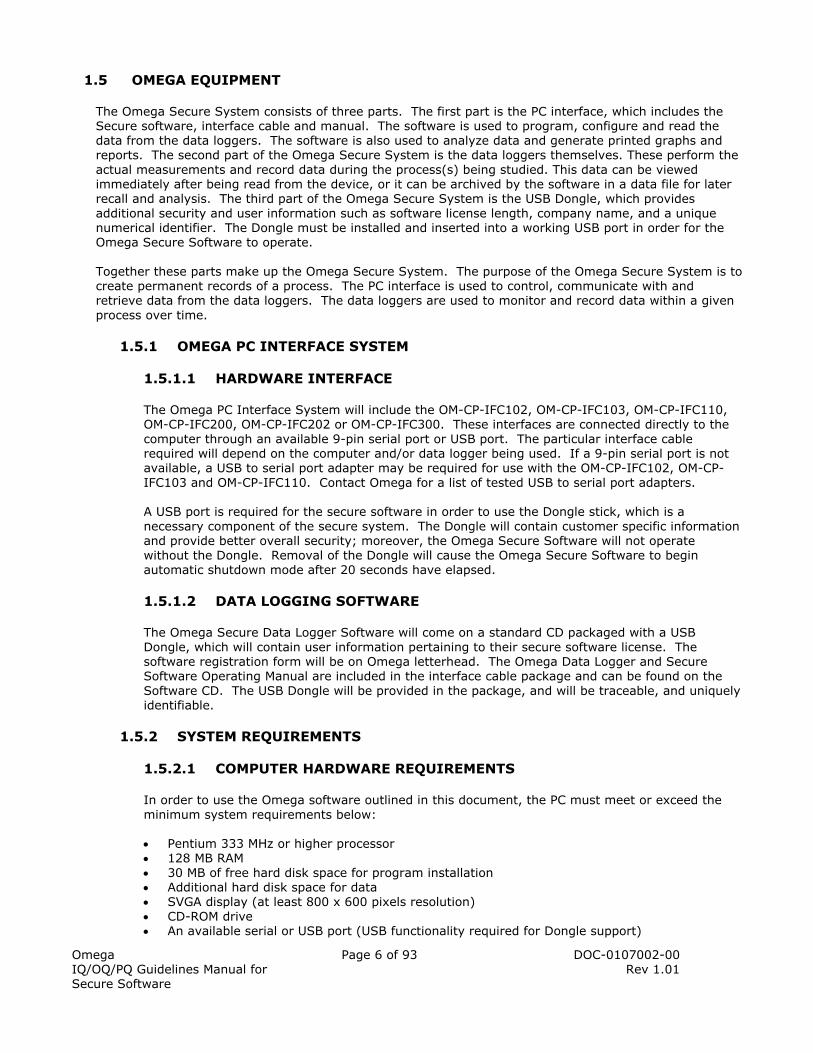
1.5 OMEGA EQUIPMENT
The Omega Secure System consists of three parts. The first part is the PC interface, which includes the Secure software, interface cable and manual. The software is used to program, configure and read the data from the data loggers. The software is also used to analyze data and generate printed graphs and reports. The second part of the Omega Secure System is the data loggers themselves. These perform the actual measurements and record data during the process(s) being studied. This data can be viewed immediately after being read from the device, or it can be archived by the software in a data file for later recall and analysis. The third part of the Omega Secure System is the USB Dongle, which provides additional security and user information such as software license length, company name, and a unique numerical identifier. The Dongle must be installed and inserted into a working USB port in order for the Omega Secure Software to operate. Together these parts make up the Omega Secure System. The purpose of the Omega Secure System is to create permanent records of a process. The PC interface is used to control, communicate with and retrieve data from the data loggers. The data loggers are used to monitor and record data within a given process over time.
1.5.1 OMEGA PC INTERFACE SYSTEM
1.5.1.1 HARDWARE INTERFACE
The Omega PC Interface System will include the OM-CP-IFC102, OM-CP-IFC103, OM-CP-IFC110, OM-CP-IFC200, OM-CP-IFC202 or OM-CP-IFC300. These interfaces are connected directly to the computer through an available 9-pin serial port or USB port. The particular interface cable required will depend on the computer and/or data logger being used. If a 9-pin serial port is not available, a USB to serial port adapter may be required for use with the OM-CP-IFC102, OM-CP-IFC103 and OM-CP-IFC110. Contact Omega for a list of tested USB to serial port adapters. A USB port is required for the secure software in order to use the Dongle stick, which is a necessary component of the secure system. The Dongle will contain customer specific information and provide better overall security; moreover, the Omega Secure Software will not operate without the Dongle. Removal of the Dongle will cause the Omega Secure Software to begin automatic shutdown mode after 20 seconds have elapsed.
1.5.1.2 DATA LOGGING SOFTWARE
The Omega Secure Data Logger Software will come on a standard CD packaged with a USB Dongle, which will contain user information pertaining to their secure software license. The software registration form will be on Omega letterhead. The Omega Data Logger and Secure Software Operating Manual are included in the interface cable package and can be found on the Software CD. The USB Dongle will be provided in the package, and will be traceable, and uniquely identifiable.
1.5.2 SYSTEM REQUIREMENTS
1.5.2.1 COMPUTER HARDWARE REQUIREMENTS
In order to use the Omega software outlined in this document, the PC must meet or exceed the minimum system requirements below: • Pentium 333 MHz or higher processor • 128 MB RAM • 30 MB of free hard disk space for program installation • Additional hard disk space for data • SVGA display (at least 800 x 600 pixels resolution) • CD-ROM drive • An available serial or USB port (USB functionality required for Dongle support)

Omega IQ/OQ/PQ Guidelines Manual for Secure Software
Page 7 of 93 DOC-0107002-00 Rev 1.01
• Keyboard and mouse • A functional printer
1.5.2.2 COMPATIBLE OPERATING SYSTEMS
The Omega Secure software is intended for use with either of the following operating systems:
• Windows 2000 • Windows XP Professional • Windows Vista
If a PC with one of the preferred operating systems is unavailable, the software is designed to run on alternate versions of Microsoft Windows. There may be additional installation or validation requirements to ensure the system operates as intended. Other compatible operating systems are:
• Windows 95 • Windows 98 • Windows ME • Windows NT4 • Windows XP Home
These operating systems may lack support for certain hardware (such as USB support), or may have limited support for some software features. Certain versions of Windows contain very limited access control features, which may affect the security of the system. Contact Omega customer service for guidance if it is necessary to install the software on an alternate operating system.
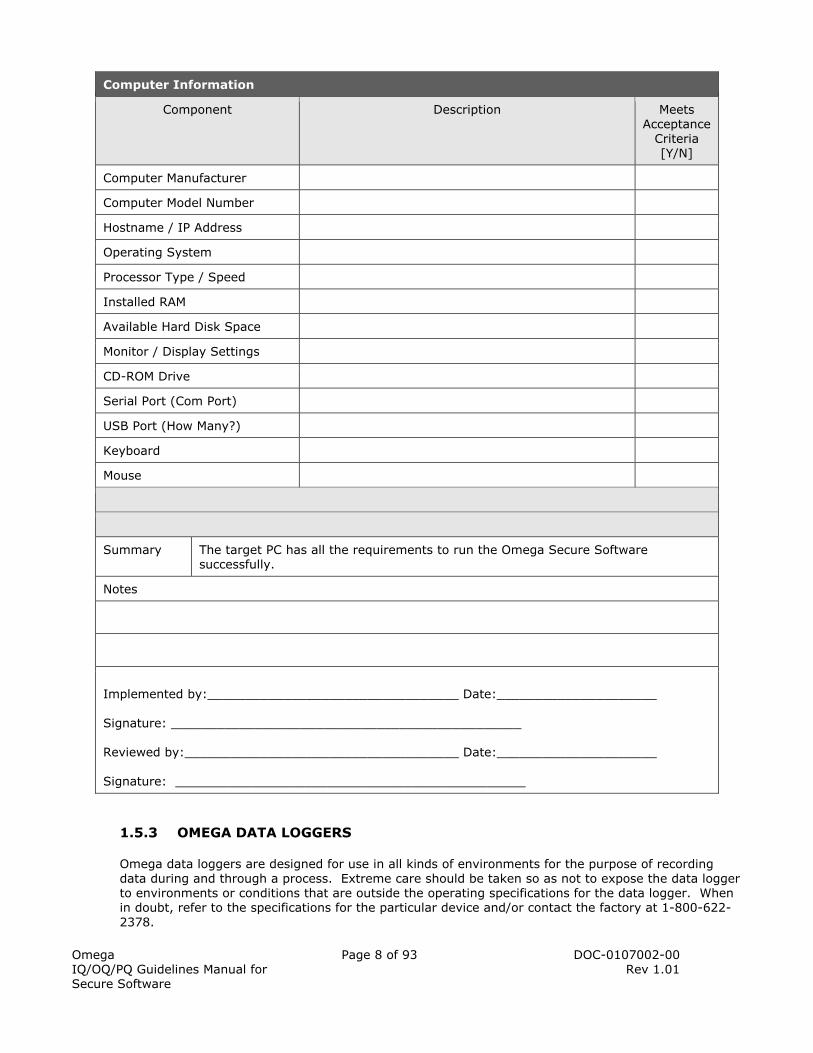
1.5.2.3 COMPUTER INFORMATION
The following table records the details of the computer used in the Omega Secure System. Complete this table to verify that the test computer meets or exceeds the minimum requirements. This information may be useful during testing, troubleshooting, or system support. The information can be documented in the Workstation Configuration Record: Workstation Properties found in the worksheet forms.
Omega IQ/OQ/PQ Guidelines Manual for Secure Software
Page 8 of 93 DOC-0107002-00 Rev 1.01
Computer Information
Component Description Meets Acceptance
Criteria [Y/N]
Computer Manufacturer
Computer Model Number
Hostname / IP Address
Operating System
Processor Type / Speed
Installed RAM
Available Hard Disk Space
Monitor / Display Settings
CD-ROM Drive
Serial Port (Com Port)
USB Port (How Many?)
Keyboard
Mouse
Summary The target PC has all the requirements to run the Omega Secure Software successfully.
Notes
Implemented by:_________________________________ Date:_____________________ Signature: ______________________________________________ Reviewed by:____________________________________ Date:_____________________ Signature: ______________________________________________
1.5.3 OMEGA DATA LOGGERS
Omega data loggers are designed for use in all kinds of environments for the purpose of recording data during and through a process. Extreme care should be taken so as not to expose the data logger to environments or conditions that are outside the operating specifications for the data logger. When in doubt, refer to the specifications for the particular device and/or contact the factory at 1-800-622-2378.

Omega IQ/OQ/PQ Guidelines Manual for Secure Software
Page 9 of 93 DOC-0107002-00 Rev 1.01
1.6 INSTALLATION QUALIFICATION PROCEDURE
This section describes the installation and setup of the Omega Secure data logging System. This includes the following:
• Proper workstation site preparation • Unpacking of Omega equipment • Installing Omega Secure Software and related components • Initiating Omega hardware connections • Verifying proper communications between the Omega data loggers and the workstation
A checklist has been provided for the person performing the installation to verify that each step has been completed. These records as well as other forms and logs produced during this procedure can be maintained as permanent records and stored.
1.6.1 SITE PREPARATION
The customer will need to provide a workstation space in a well-lit area with a table or desk that is suitable and comfortable for computer operation. The space around the computer should be cleared of anything that is not related to the immediate task of setting up and connecting the Omega Secure System to the computer and programming the Omega data loggers.
The ambient temperature and humidity limitations are the same as those specified for the computer in which the Omega interface and data loggers are connected. The storage environment for the Omega interface and data loggers should be maintained at an ambient temperature within the range of 10°C to 50°C (50°F to 122°F) and a relative humidity between 0%RH and 95%RH, non-condensing. An antistatic mat, grounded wristband, or other standard electrical precautions are recommended whenever measurement or communications hardware are connected to a PC.
1.6.2 UNPACKING THE OMEGA SYSTEM
In most cases, the complete Omega system will be shipped in a single box that will contain all the necessary hardware and software. In that box will be a container for the PC interface system, one or more data loggers and an envelope containing a calibration report for each data logger (if purchased).
The following checklist can be used for receiving the container that contains the PC Interface:
Item Received By/Date
Omega Secure data logger software CD
Omega Secure USB Dongle Stick
Omega Secure Software Registration Form
Item Received By/Date
Interface cable and adapters (if required)
Omega Data Logger and Secure Software Operating Manual

Omega IQ/OQ/PQ Guidelines Manual for Secure Software
Page 10 of 93 DOC-0107002-00 Rev 1.01
The following checklist can be used for receiving the Omega data loggers and their individual calibration reports:
Item Quantity Received By/Date
Omega data logger(s)
Calibration certificate(s) (if purchased)
The packing list should be retrieved and used for checking the materials in the package and for comparison with the original purchase order. The packing list will contain the serial numbers of each data logger. This number should be matched against the serial number written on each data logger and of that listed on each calibration certificate. The calibration certificates serve as original documentation regarding the accuracy of the data loggers, and the originals should be kept on file in a safe location. It is recommended that these forms be copied and filled out appropriately and stored in a convenient location near the workstation. The Omega Data Logger and Secure Software Operating Manual are included with the purchase of an interface cable and are installed on the target computer during the normal installation process. The drivers for the OM-CP-IFC200, OM-CP-IFC202 or OM-CP-IFC300 USB interface cable are also available on the Omega Data Logger Software CD.
1.6.3 OMEGA SECURE DATA LOGGER SOFTWARE INSTALLATION
The Omega Secure data logger software includes an automatic installation program that will start the installation process when the CD is inserted into the CD-ROM drive. This installation program should work with all specified Windows operating systems. On some systems, the Windows autorun feature may have been manually disabled. On these systems, the user will need to execute the “autorun.exe” program on the CD to begin the installation process. The following procedure is used to install the Omega Secure data logger software. The individual performing the installation should initial the appropriate box upon completion of each step and sign and date the end of the procedure after completion.
Software Installation
Step Task Acceptance Criteria Initial
1 Prior to beginning the installation process, ensure that any previously installed versions of Omega software have been completely uninstalled. This ensures that the proper versions of all components will be installed.
There will not be any versions of the Omega Software installed on the designated PC prior to the installation of the Omega Secure Software.
2 Insert the Omega Secure software CD into the CD-ROM drive.
The automatic installation software should start running and present the user with the following options: ‘Security Key Driver and Utility’ ‘Omega Software’ ‘Drivers and Third Party Tools’ ‘View Documentation and Resources’ If the autorun does not start, locate the CD in ‘My Computer’ and execute the autorun file.
3 Click ‘Security Key Driver and Utility’. A screen will appear with the following options: ‘Install Sentinel System Driver’ ‘Install Security Update Utility’

Omega IQ/OQ/PQ Guidelines Manual for Secure Software
Page 11 of 93 DOC-0107002-00 Rev 1.01
4 Ensure that the USB Dongle is not inserted into the PC.
The USB Dongle is not inserted into the PC.
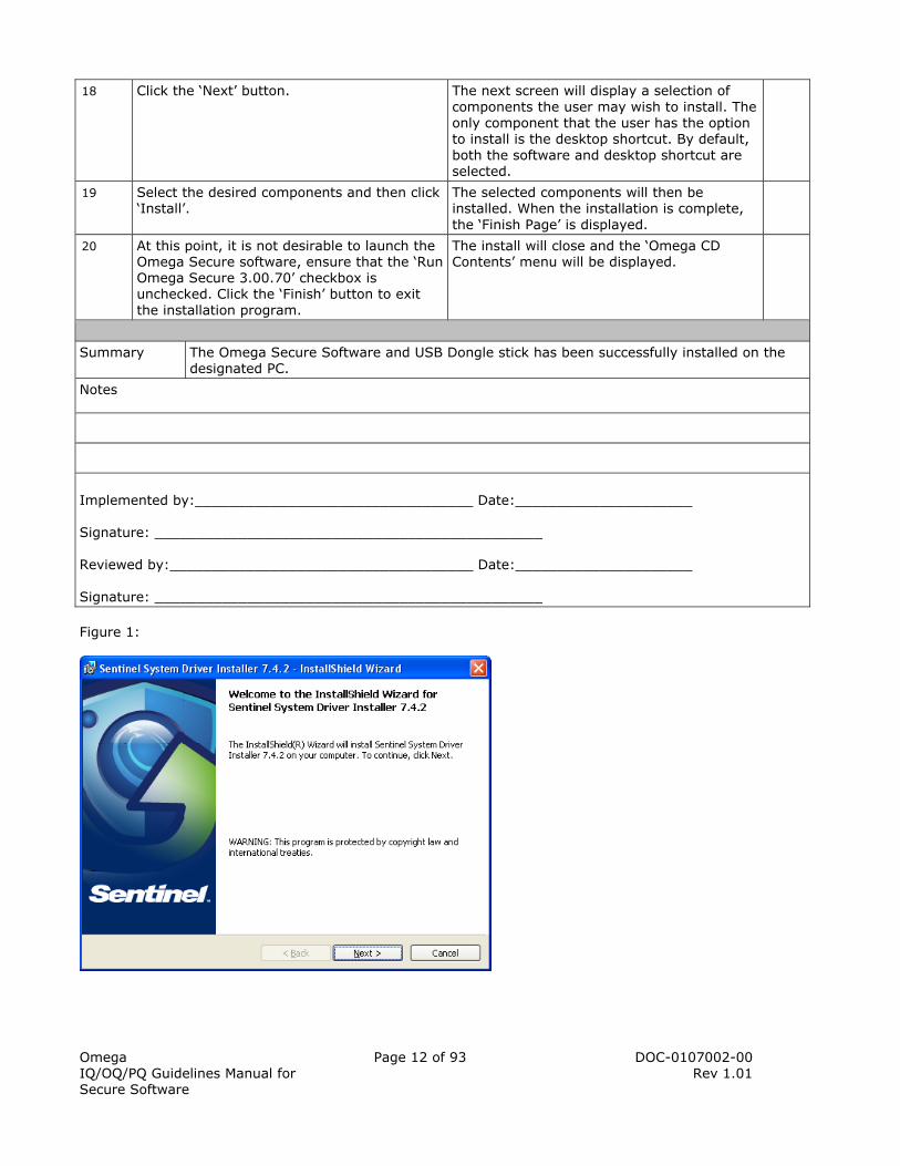
5 Click ‘Install Sentinel System Driver’. Refer to Figure 1 below for a screenshot.
The Sentinel installer will appear.
6 Click ‘Next’. The Sentinel License agreement will appear.
7 Read the terms of the License Agreement and then check the box that says: ‘I accept the terms in the license agreement’. Refer to Figure 2 below for a screenshot. Click ‘Next’.
The installer will present the following options: ‘Complete’ ‘Custom’
8 Ensure that ‘Complete’ is checked. And click ‘Next’. Refer to Figure 3 below for a screenshot.
A window will appear asking the user if it is time for installation.
9 Click the ‘Install’ button. The Sentinel Installer will install the drivers onto the users PC. A window appears in which the user can click ‘Finish’ to complete the driver installation.
10 Click ‘Finish’ and insert the USB Dongle stick. Refer to Figure 4 below for a screenshot.
The USB Dongle stick is inserted and the green LED lights up.
11 Click ‘Back to Omega CD Contents’. The Omega CD Contents screen will be displayed.
12 Click ‘Omega Software’. A screen will appear with the following options: ‘Install Omega 3.00.70’ ‘Install Relay 1.02 Software’
13 Click ‘Install Omega 3.00.70’ The installation program will start and a ‘Prepare to Install …’ status box will be displayed. After a short delay, the installation program will continue. If this is the first installation of the software on this computer, you will be prompted to select a language to use for the installation setup program.
14 Select a language from the drop down menu and click on the ‘OK’ button to continue. If this is not the first installation, the previously chosen language is the default.
The ‘Omega Secure 3.00.70 Setup’ screen is displayed. This screen provides details about the software that is to be installed.
15 Click the ‘Next’ button to continue. The ‘License Agreement’ page is the next window displayed.
16 Read the License Agreement and place a check in the box next to ‘I accept the terms in the License Agreement’ to accept the terms. Click the ‘Next’ button.
The next screen will let the user choose the installation location. The default is ‘C:\Program Files\Omega Secure 3.00’. If you wish to change the location, choose the location from this window. Document the new location in the Notes section at the end of this procedure.
17 Click the ‘Next’ button. The next screen lets the user choose the program shortcut in the start menu. By default, the location is set to Omega Secure 3.00.
Omega IQ/OQ/PQ Guidelines Manual for Secure Software
Page 12 of 93 DOC-0107002-00 Rev 1.01
18 Click the ‘Next’ button. The next screen will display a selection of components the user may wish to install. The only component that the user has the option to install is the desktop shortcut. By default, both the software and desktop shortcut are selected.
19 Select the desired components and then click ‘Install’.
The selected components will then be installed. When the installation is complete, the ‘Finish Page’ is displayed.
20 At this point, it is not desirable to launch the Omega Secure software, ensure that the ‘Run Omega Secure 3.00.70’ checkbox is unchecked. Click the ‘Finish’ button to exit the installation program.
The install will close and the ‘Omega CD Contents’ menu will be displayed.
Summary The Omega Secure Software and USB Dongle stick has been successfully installed on the designated PC.
Notes
Implemented by:_________________________________ Date:_____________________ Signature: ______________________________________________ Reviewed by:____________________________________ Date:_____________________ Signature: ______________________________________________
Figure 1:

Omega IQ/OQ/PQ Guidelines Manual for Secure Software
Page 13 of 93 DOC-0107002-00 Rev 1.01
Figure 2:
Figure 3:

Omega IQ/OQ/PQ Guidelines Manual for Secure Software
Page 14 of 93 DOC-0107002-00 Rev 1.01
Figure 4:
1.6.4 INTERFACE DRIVER INSTALLATION
The following table details the procedure required for installing the required USB drivers for the Omega USB interface cables (i.e. OM-CP-IFC200, OM-CP-IFC202 and OM-CP-IFC300). This step should only be completed for systems that include a USB interface cable. If the USB interface cable will be installed at a later date, this procedure may be performed at that time. The individual performing the installation should initial the appropriate box upon completion of each step and sign and date the end of the procedure after completion. IMPORTANT NOTES: The USB interface drivers MUST be installed before connecting the USB interface cable hardware to the workstation. The Omega Secure software should not be running during the driver installation. Locate the printed ‘USB Data logger Interface Quick Installation Guide’ provided with the USB interface package. Reference this document during this procedure and the system connection phase of the installation.
USB Driver Installation
Step Task Acceptance Criteria Initial
1 Starting from the ‘Omega CD Contents’ menu click ‘Back to Omega CD Contents’.
The initial installation screen will be shown.
2 Click ‘Drivers and Third Party Tools’. The screen will change to the following options: ‘Install USB Interface Drivers’ ‘Install Tibbo Software (Ethernet Device Server)’

Omega IQ/OQ/PQ Guidelines Manual for Secure Software
Page 15 of 93 DOC-0107002-00 Rev 1.01
3 Note. If using a USB interface cable, ensure the cable is disconnected from the target PC before continuing. Click ‘Install USB Interface Drivers’.
The driver installation program will start and an ‘Install Driver’ window will be displayed. By default, the drivers are set to be installed to the default data recorder software directory. To change the location, click the browse button and select a new installation directory. Document the new directory in the notes section.
4 Click the ‘Install’ button to continue to install the interface drivers.
As described in Step #1 of the Quick Installation Guide, it may be required to perform additional actions to complete the driver installation. Continue the driver installation as instructed until the ‘Installation Successful’ dialog box is displayed.
5 Click ‘OK’ to close the ‘Installation Successful’ dialog.
The ‘Omega CD Contents’ menu will be displayed.
Summary The USB Driver Installation is complete.
Notes
Implemented by:_________________________________ Date:_____________________ Signature: ______________________________________________ Reviewed by:____________________________________ Date:_____________________ Signature: ______________________________________________
1.6.5 OMEGA DATA LOGGER SECURE SYSTEM PC CONNECTION
The following procedure details the steps required for completing the Omega Secure System connections. The individual performing the installation should initial the appropriate box upon completion of each step and sign and date the end of the procedure after completion.
System Connection
Step Task Acceptance Criteria Initial
1 Clear an area next to the computer as a work area where access to the serial port or USB port (usually located on the rear of the computer) is available.
The computer area will be clear of any debris and or clutter. The ports on the hard drive will be easily accessible.
2 Arrange the PC interface components for easy access and reference.
The interface cable is ready to be plugged in.

Omega IQ/OQ/PQ Guidelines Manual for Secure Software
Page 16 of 93 DOC-0107002-00 Rev 1.01
3 Position the interface cable to make connection with the serial or USB port on the target machine. Carefully and gently connect the interface to the appropriate connector on the computer (i.e. 9-pin male serial port or USB port). Do not force the connection as this may cause damage to the connectors. Ensure that there is a good connection to minimize the chance of communication errors. If using a 9-pin serial interface cable, use a small flat head screwdriver to tighten the thumbscrews on the serial interface cable. This will prevent accidental dislodging of the cable from the computer and disrupting communications. This step is not necessary when using a USB interface cable.
The interface cable will be securely connected to the PC.
4 Place the other end of the interface cable on a flat surface in a convenient location near the computer.
The 9-pin serial interface cable is ready for use. If using a USB interface cable, continue to step #5.
5 If using a USB interface cable, additional steps may need to be completed, as described in step #2 of the ‘USB Data Logger Interface Quick Installation Guide’ provided with the USB interface package. Complete the steps appropriate to the target PC and confirm that the steps execute as indicated.
The USB interface cable will be ready for use.
Summary The Omega interface cable is successfully connected to the PC.
Notes
Implemented by:_________________________________ Date:_____________________ Signature: ______________________________________________ Reviewed by:____________________________________ Date:_____________________ Signature: ______________________________________________
1.6.6 LAUNCHING THE OMEGA SECURE SOFTWARE
The following procedure verifies that the Omega Secure data logger software was installed properly on the target computer and that it can be started on the workstation. The individual performing the installation should initial the appropriate box upon completion of each step and sign and date the end of the procedure after completion.

Omega IQ/OQ/PQ Guidelines Manual for Secure Software
Page 17 of 93 DOC-0107002-00 Rev 1.01
Launching the Software
Step Task Acceptance Criteria Initial
1 Close the ‘Omega CD Contents’ window by clicking ‘Exit CD Browser’.
The ‘Omega CD Contents’ box will close.
2 Start the Omega Secure software. If a desktop shortcut was created, click on the Omega Icon to start the software. If start menu shortcuts were created, select the ‘Omega Secure 3.00.70’ from the start menu to start the software. Otherwise, launch the program by opening the ‘Omega3.exe’ executable located in the installation directory.
A box will appear that says “Database not available”.
3 Click “OK” to continue. A box will appear that says “Database not available”.
4 Click “OK” to continue. A box will appear that says “Database not available”.
5 Click “OK” to continue. The ‘Omega Secure Data Recorder Software Registration’ box will be open and active. The Software Information section will match that on the Omega Secure Software Registration Form.
6 Enter the User Name, Company Name, License Key, and License Password exactly as provided by the Omega Secure Software Registration Form.
The Software Information section will be filled out with the same information that is on the Registration Form.
7 Click ‘Register’ to continue. A prompt will appear to set the password for the administrator account. A note will indicate: ‘Please set the password for the administrator account. The default password for this account is the license password’.
8 Click ‘OK’ to continue. The ‘Set Password’ box will appear. The default password is the license password. Omega recommends keeping the license password as the administrator password so that if required, Omega technical support can look up information. The administrator account is intended for initial system setup and system recovery in the event of a problem. The password is not changed.
9 Click ‘OK’ to continue. A prompt will appear notifying that an Audit Trail database will be created in the directory the software was installed to.
10 Click ‘OK’ to continue. A prompt will appear notifying that a Secure folder does not exist and it will be created in the directory the software was installed to.
11 Click ‘OK’ to continue. A prompt will appear notifying that a System database does not exist and it will be created in the directory the software was installed to.

Omega IQ/OQ/PQ Guidelines Manual for Secure Software
Page 18 of 93 DOC-0107002-00 Rev 1.01
12 Click ‘OK’ to continue. A prompt will appear notifying that a Users database does not exist and it will be created in the directory the software was installed to.
13 Click ‘OK’ to continue. A prompt will appear confirming the software has successfully created user directories. \secure\administrator\backup \secure\administrator\data
14 Click ‘OK’ to continue. Note. That administrator should set access permissions in the operating system in order to ensure data integrity. Refer to the Omega Data Logger and Secure Software Operating Manual for more details.
The Omega Secure Login prompt will appear.
15 Enter ‘administrator’ as the user name and enter the password (license key). Click ‘Login’ to continue.
The Omega Secure software will now be running. At the top of the software program it will read Omega Secure – [Graph]. No error messages should be received during the launch. However, depending on the hardware configuration, a warning may be received indicating that no communication port is selected, or unable to open Com X, ‘Invalid Port (33025)’. Click OK to continue. Note. “Com X” can be com ports 1-8.
16 Close the Omega Secure Software using the ‘X’ button in the upper right hand corner of the software.
The software will close normally without reporting any errors.
Summary The Omega software has been successfully installed; the administrator has logged in, and the software runs properly on the PC.
Notes
Implemented by:_________________________________ Date:_____________________ Signature: ______________________________________________ Reviewed by:____________________________________ Date:_____________________ Signature: ______________________________________________
1.6.7 COMMUNICATIONS PROCEDURE
The following procedure is used to verify that proper communications takes place and occurs between the computer and the Omega data logger(s). The individual performing the installation should initial the appropriate box upon completion of each step and sign and date the end of the procedure after completion.

Omega IQ/OQ/PQ Guidelines Manual for Secure Software
Page 19 of 93 DOC-0107002-00 Rev 1.01
Communication with Data Logger
Step Task Acceptance Criteria Initial
1 Start the Omega Secure Software as described in section 1.6.6.
The Omega Secure Login prompt will appear.
2 Enter ‘administrator’ as the username and the correct password. Click ‘Login’ to continue.
The Omega Secure software will be running. If an interface cable is not configured, a “No Communications Port Selected” will appear. Refer to section 1.6.4 for interface driver installation.
3 Connect a data logger to the interface cable that is connected to the PC.
The 3.5mm stereo plug will be securely connected to a data logger.
4 Through the software click ‘Communication->Autoconfigure Port’
A “Processing, please wait” message will appear followed by a message stating that a data logger was found.
5 Click “OK”. The message box will close and the Device Status screen will appear.
6 Verify that the device type reported in the ‘Device Status’ window matches the data logger that is connected. Inspect the configuration parameters and device properties reported in the window and confirm that they appear to be reasonable compared to the specifications.
The reported configuration matches the device that is connected, and the communications procedure is successful.
7 Click ‘OK’. The Device Status box will close.
8 Click ‘File’, then ‘Exit’. The Omega Secure Software program will close.
Summary The data logger successfully communicates with the installed software.
Notes
Implemented by:_________________________________ Date:_____________________ Signature: ______________________________________________ Reviewed by:____________________________________ Date:_____________________ Signature: ______________________________________________
1.6.8 SETUP VERIFICATION RECORD
The following table should be initialized and dated by the appropriate personnel. Any problems or failures along with corrective measures taken should be recorded on additional sheets attached to this form. The individual performing the installation should initial the appropriate box upon completion of each step and sign and date the end of the procedure after completion.
Verification Records
Step Task Initial
1 All required Omega equipment was present at installation.

Omega IQ/OQ/PQ Guidelines Manual for Secure Software
Page 20 of 93 DOC-0107002-00 Rev 1.01
2 Site preparation was done in accordance with specifications.
3 Secure USB Dongle was installed properly and is inserted into the PC.
4 Omega Secure data logger software installation was completed according to instructions.
5 Required driver software was installed, if required.
6 PC interface cable was installed according to instructions.
7 Omega Secure data logger software properly starts with no error messages.
8 Initial configuration of Omega Secure data logger software is completed.
9 Communication with at least one Omega data logger was verified.
Summary Verification of the Omega Secure Installation Qualification is complete and documented.
Notes
Implemented by:_________________________________ Date:_____________________ Signature: ______________________________________________ Reviewed by:____________________________________ Date:_____________________ Signature: ______________________________________________
1.7 SYSTEM ACCEPTANCE
This system is properly installed and has passed all functional procedures.
Installed By:
(Print Name)
Signature: Date:
Functional Procedures Performed By:
(Print Name)
Signature: Date:
Approved By:
(Print Name)
Signature: Date:

Omega IQ/OQ/PQ Guidelines Manual for Secure Software
Page 21 of 93 DOC-0107002-00 Rev 1.01
2 OPERATIONAL QUALIFICATION (OQ)
Omega, Inc. supplies this Operational Qualification (OQ) document as a reference for and aid to the user for validation requirements associated with the use and operation of the Omega Secure System in a regulated environment. This document is designed to help develop the customer’s validation plan as defined in the FDA current Good Manufacturing Practice (see 21 CFR 820). Each user of the Omega Secure software must complete the sections listed in the ‘Employee Training Record’ to ensure that they have completed sufficient training using the Omega Secure Data Recorder Software. Complete the appropriate ‘Employee Training Record’ for each employee to keep a record of the users who have been trained.
2.1 PURPOSE
The purpose of this document is to establish that the Omega Secure System functions as specified on the workstation in the selected environment.
2.2 RESPONSIBILITIES
For a complete Omega Secure System, there are responsibilities of Omega, Inc. as well as the end user for compliance with 21 CFR Part 11. These responsibilities apply to the OQ procedure and are required to be maintained throughout using the Omega Secure System. Standard operating procedures should be created and implemented for responsibilities.
2.2.1 OMEGA
• OQ Protocol template and acceptance guidelines • Example Worksheet forms
2.2.2 END USER
• OQ Protocol preparation and approval • Site preparation • Protocol execution • Documentation, review, and approval of results • Documentation, review, and acceptance of deviations from protocol • Limiting system access • Defining user roles in the system • Creating and updating accounts • Ensuring user identity and personal accountability • Defining appropriate values for system settings • Training users • Periodic review of the audit trail, security settings and user accounts • Software maintenance and updates • Secure USB Dongle Maintenance and updating
2.3 SCOPE
The OQ Procedure for the Omega Secure System provides:
• Functional verification of Omega data loggers • Handling and maintenance information for the use of Omega equipment • Omega operating procedures for primary functions • Verification that the installation of Omega equipment is completed properly • Creating and configuring user accounts • Periodic calibration verification in the field • Verification of proper communication between the Omega data logger(s) and the workstation(s)

Omega IQ/OQ/PQ Guidelines Manual for Secure Software
Page 22 of 93 DOC-0107002-00 Rev 1.01
2.4 DATA LOGGER HANDLING AND MAINTENANCE
This section describes the proper handling and maintenance of the Omega data loggers. The following safety considerations and precautions should be observed during the use of the Omega data loggers.
2.4.1 DATA LOGGER HANDLING
• Treat the data loggers and their associated components carefully. They are precision instruments.
• Do not expose any Omega data logger outside its specified operating range. For example, most Omega products are specified to operate from -40ºC to +80ºC and from 0%RH to 95%RH. Consult product datasheets for specified operating conditions.
• Each Omega data logger should be clean, kept free of contaminants and allowed to cool down to ambient temperature before connecting/disconnecting to any equipment. Not following these guidelines could cause damage to the equipment and/or the data logger.
• Periodically check the Omega data loggers against a known good standard such as the National Institute of Standards and Technology (NIST) to verify the device calibration. The total system uncertainty should not be more than 25% of the accuracy desired for the calibration, per ANSI Z540-1-1994 10.2b.
• The IS versions of Omega data loggers are considered to be intrinsically safe. Intrinsically Safe ratings are issued by Factory Mutual (FM). Examples of Omega IS-rated data loggers include the OM-CP-Temp1000IS, OM-CP-RHTemp1000IS, OM-CP-PRTemp1000IS and the OM-CP-PRTrans1000IS. The following conditions must be satisfied to maintain the IS rating of the Omega products:
o When used in hazardous locations, the IS Series data loggers are to be installed prior to the location becoming hazardous, and removed only after the area is no longer hazardous.
o The maximum allowed ambient temperature for the IS Series data loggers (under any circumstances) is 80°C (176°F). The minimum rated operating temperature is -40°C (40°F).
o The IS Series data loggers are approved for use only with the Tadiran TL-2150 battery. Replacement with any other battery will void the safety rating.
o Batteries are user replaceable, but they may only be removed or replaced in locations that are known to be non-hazardous.
o Tampering with or replacement of non-factory components may adversely affect the use of the product, and is prohibited. Except for replacement of the battery, the user may not service the IS Series data loggers. Omega or an authorized representative must perform all other service to the product.
o The OM-CP-Temp1000IS enclosure is rated NEMA 4X, 6P, so it is suitable for use in both indoor and outdoor locations. However, to maintain the NEMA rating, the cover must be fully closed and secured.
o The OM-CP-RHTemp1000IS, OM-CP-PRTemp1000IS, and OM-CP-PRTrans1000IS enclosures do not carry a NEMA rating. For this reason, the products are only suitable for use in indoor locations.
2.4.2 BATTERIES
Most Omega batteries are field replaceable. In addition, most Omega batteries are Lithium Thionyl Chloride batteries. This means that special precautions and warnings must be heeded. The following warning should be read and appears on most Omega loggers and documentation:
2.4.2.1 BATTERY WARNING
Most Omega data loggers contain a lithium battery. Do not cut the battery open, incinerate, or recharge. Do not heat lithium batteries above 85ºC (185°F) unless the battery is specifically rated

Omega IQ/OQ/PQ Guidelines Manual for Secure Software
Page 23 of 93 DOC-0107002-00 Rev 1.01
for higher temperatures. Dispose the battery in accordance with local regulations. Refer to the product datasheet for the battery warning for that product.
2.5 CREATING ADMINISTRATIVE USER
The user name ‘administrator’ is designed to be a backup login for the entire system. The designated user, who maintains the Omega Secure System, should set up a unique user name with administrative privileges. The account made in this procedure should be used from this point forward to complete the OQ section, this account is referred to as the ‘administrative user’ or ‘administrative account’ in the remainder of this document. The designated administrator is determined by the company implementing the software. Amongst other responsibilities, maintaining the security settings are part of the administrator’s responsibility. Use the Workstation Account Summary: Account List form to document this information. The individual performing the installation should initial the appropriate box upon completion of each step and sign and date the end of the procedure after completion.
Creating Administrative User
Step Task Acceptance Criteria Initial
1 Open the Omega Secure software. The login screen will appear.
2 Enter ‘administrator’ for the username and the correct password. Click ‘Login’.
The software will now be running. If a USB interface cable was previously installed, a message may appear: ‘Unable to open USB port’, click ‘OK’ to continue.
3 Click the ‘System’ menu, then ‘User Management’.
The ‘User Management’ screen will appear.
4 Verify there is only one User ID, and the username is ‘administrator’. The Account Information and the Account Status sections are disabled.
In the User Management screen, only the default administrator will be documented and the Account Information and the Account Status sections are disabled.
5 Click the ‘New’ button in the bottom left corner of the ‘User Management’ window to create a new user.
The ‘New’ button will now read ‘Save’ and is disabled. The Account Information and Account Status sections are now active.
6 In the ‘User Name’ text box, type in the user name for the new administrative account. Omega recommends that the user name is written in lowercase letters, but the user name is case insensitive.
The ‘User Name’ field will be filled out.
7 The ‘Home Directory’ field will now have gray text written in it. Click on the ‘Home Directory’ field and scroll to the right, verify that the last word in the path is the user name.
The last word in the file name will be the user name.
8 The ‘User ID’ field will read ‘2’. The ‘User ID’ field will read ‘2’.
9 Click on the ‘Group’ Dropdown box; choose ‘1 – Administrators’.
The ‘Group’ Dropdown box will read ‘1 – Administrators’.
10 In the ‘Full Name’ field, type in the full name of the user. Omega recommends the full name include the first name, middle initial and last name.
The ‘Full Name’ field will be complete with the full name of the user.
Omega IQ/OQ/PQ Guidelines Manual for Secure Software
Page 24 of 93 DOC-0107002-00 Rev 1.01
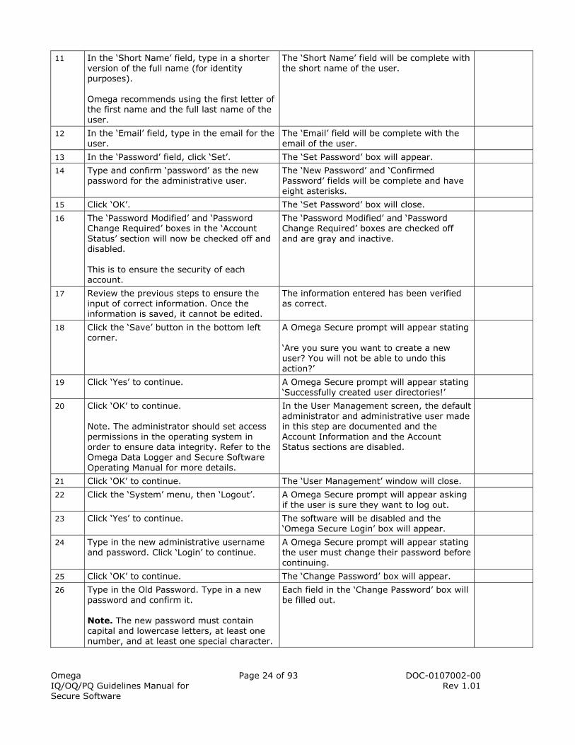
11 In the ‘Short Name’ field, type in a shorter version of the full name (for identity purposes). Omega recommends using the first letter of the first name and the full last name of the user.
The ‘Short Name’ field will be complete with the short name of the user.
12 In the ‘Email’ field, type in the email for the user.
The ‘Email’ field will be complete with the email of the user.
13 In the ‘Password’ field, click ‘Set’. The ‘Set Password’ box will appear.
14 Type and confirm ‘password’ as the new password for the administrative user.
The ‘New Password’ and ‘Confirmed Password’ fields will be complete and have eight asterisks.
15 Click ‘OK’. The ‘Set Password’ box will close.
16 The ‘Password Modified’ and ‘Password Change Required’ boxes in the ‘Account Status’ section will now be checked off and disabled. This is to ensure the security of each account.
The ‘Password Modified’ and ‘Password Change Required’ boxes are checked off and are gray and inactive.
17 Review the previous steps to ensure the input of correct information. Once the information is saved, it cannot be edited.
The information entered has been verified as correct.
18 Click the ‘Save’ button in the bottom left corner.
A Omega Secure prompt will appear stating ‘Are you sure you want to create a new user? You will not be able to undo this action?’
19 Click ‘Yes’ to continue. A Omega Secure prompt will appear stating ‘Successfully created user directories!’
20 Click ‘OK’ to continue. Note. The administrator should set access permissions in the operating system in order to ensure data integrity. Refer to the Omega Data Logger and Secure Software Operating Manual for more details.
In the User Management screen, the default administrator and administrative user made in this step are documented and the Account Information and the Account Status sections are disabled.
21 Click ‘OK’ to continue. The ‘User Management’ window will close.
22 Click the ‘System’ menu, then ‘Logout’. A Omega Secure prompt will appear asking if the user is sure they want to log out.
23 Click ‘Yes’ to continue. The software will be disabled and the ‘Omega Secure Login’ box will appear.
24 Type in the new administrative username and password. Click ‘Login’ to continue.
A Omega Secure prompt will appear stating the user must change their password before continuing.
25 Click ‘OK’ to continue. The ‘Change Password’ box will appear.
26 Type in the Old Password. Type in a new password and confirm it. Note. The new password must contain capital and lowercase letters, at least one number, and at least one special character.
Each field in the ‘Change Password’ box will be filled out.
Omega IQ/OQ/PQ Guidelines Manual for Secure Software
Page 25 of 93 DOC-0107002-00 Rev 1.01
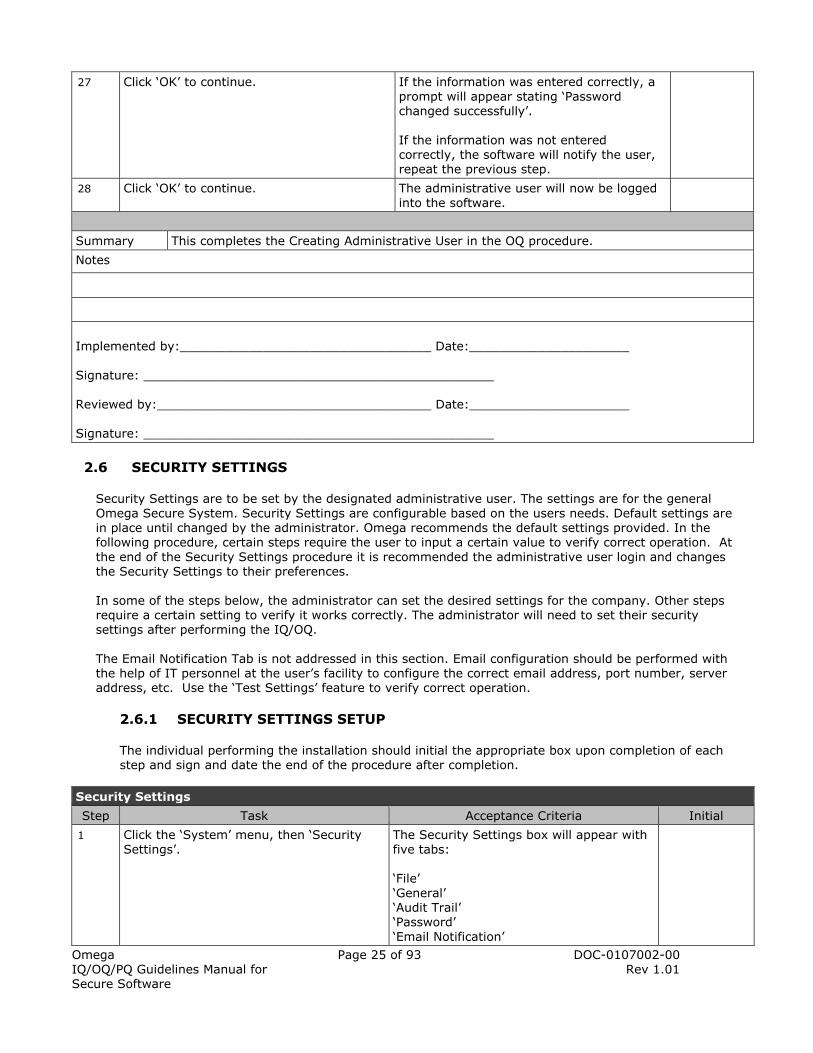
27 Click ‘OK’ to continue. If the information was entered correctly, a prompt will appear stating ‘Password changed successfully’. If the information was not entered correctly, the software will notify the user, repeat the previous step.
28 Click ‘OK’ to continue. The administrative user will now be logged into the software.
Summary This completes the Creating Administrative User in the OQ procedure.
Notes
Implemented by:_________________________________ Date:_____________________ Signature: ______________________________________________ Reviewed by:____________________________________ Date:_____________________ Signature: ______________________________________________
2.6 SECURITY SETTINGS
Security Settings are to be set by the designated administrative user. The settings are for the general Omega Secure System. Security Settings are configurable based on the users needs. Default settings are in place until changed by the administrator. Omega recommends the default settings provided. In the following procedure, certain steps require the user to input a certain value to verify correct operation. At the end of the Security Settings procedure it is recommended the administrative user login and changes the Security Settings to their preferences. In some of the steps below, the administrator can set the desired settings for the company. Other steps require a certain setting to verify it works correctly. The administrator will need to set their security settings after performing the IQ/OQ.
The Email Notification Tab is not addressed in this section. Email configuration should be performed with the help of IT personnel at the user’s facility to configure the correct email address, port number, server address, etc. Use the ‘Test Settings’ feature to verify correct operation.
2.6.1 SECURITY SETTINGS SETUP
The individual performing the installation should initial the appropriate box upon completion of each step and sign and date the end of the procedure after completion.
Security Settings
Step Task Acceptance Criteria Initial
1 Click the ‘System’ menu, then ‘Security Settings’.
The Security Settings box will appear with five tabs: ‘File’ ‘General’ ‘Audit Trail’ ‘Password’ ‘Email Notification’

Omega IQ/OQ/PQ Guidelines Manual for Secure Software
Page 26 of 93 DOC-0107002-00 Rev 1.01
2 Verify in the ‘File’ tab, there is a list of the following directory locations and they are disabled. ‘Secure File Path’ ‘System File’ ‘Audit Trail File’ ‘Users File’ These fields indicate the current location of the files. Note: The IT department can help move the file locations to secure folders.
In the ‘File’ tab, there will be a list of the following directory locations and they will be disabled. ‘Secure File Path’ ‘System File’ ‘Audit Trail File’ ‘Users File’
3 Select the ‘General’ tab and verify that it contains the following information: ‘Settings’ ‘Invalid Login Threshold’ ‘Lockout Duration’ ‘Enable Console Lock’ ‘Inactivity Duration’ ‘Statistics’ ‘Invalid Login Attempts’ ‘Last Invalid Login Attempt’ ‘Last Lockout Date’
The following information is contained in the ‘General’ tab: ‘Settings’ ‘Invalid Login Threshold’ ‘Lockout Duration’ ‘Enable Console Lock’ ‘Inactivity Duration’ ‘Statistics’ ‘Invalid Login Attempts’ ‘Last Invalid Login Attempt’ ‘Last Lockout Date’
4 The ‘Invalid Login Threshold’ box defines the number of times a user can try to login with an incorrect password. Enter ‘3’ in the ‘Invalid Login Threshold’ box.
The number ‘3’ will be written in the ‘Invalid Login Threshold’ box.
5 In the ‘Lockout Duration’ time box, enter 1 minute. This value will be tested in a future procedure. This is the amount of time the user will have to wait before being allowed to enter their password to login again.
The time in the ‘Lockout Duration’ box is 1 minute [00:01:00].
6 ‘Enable Console Lock’ locks the software after a certain amount of in-activity. Leave the box checked to enable it.
The “Enable Console Lock” box will be checked.
7 In the ‘Inactivity Duration’ time box, this defines the amount of time of inactivity before the software locks. Enter 5 minutes.
The time in the ‘Inactivity Duration’ box is 5 minute [00:05:00].
8 Select the ‘Audit Trail’ tab and verify that it contains the following information. ‘File Settings’ ‘Maximum Size’ ‘Maximum File Life’ ‘Begin New Audit Trail’
The ‘Audit Trail’ tab will contain the following information. ‘File Settings’ ‘Maximum Size’ ‘Maximum File Life’ ‘Begin New Audit Trail’

Omega IQ/OQ/PQ Guidelines Manual for Secure Software
Page 27 of 93 DOC-0107002-00 Rev 1.01
9 The ‘Maximum Size’ defines the amount of records to document before starting a new audit trail. Type in the preferred number of records to document. Note: The number of records documented must be greater than or equal to 16. Number of records :_____________
The number of records written in the box to the left matches the number in the ‘Maximum Size’ box.
10 The ‘Maximum File Life’ defines the amount of days to document before starting a new audit trail. Type in the preferred number of days to document the audit trail. Number of days:________________
The number of days written in the box to the left matches the number in the ‘Maximum File Life’ box.
11 Click the ‘Begin New Audit Trail’ button. A message appears: ‘The security settings that have been edited must be saved before continuing. Do you want to save the changes made to the security settings?’
12 Click ‘Yes’ to continue. A box will appear with the message: ‘Successfully started new audit trail file: Audit001.mdb’.
13 Click ‘OK’ to continue. The screen will return to the Security Settings box.
14 Click on the ‘Password’ tab and verify it contains the following information. ‘Complexity’ ‘Minimum Length’ ‘Maximum Length’ ‘Require Mixed Case’ ‘Require Alpha-Numeric’ ‘Require Special Characters’ ‘Expiration’ ‘Expiration Interval’ ‘Warning Interval’ ‘History’ ‘History Length’ ‘Number of old passwords’
The ‘Password’ tab will contain the following information. ‘Complexity’ ‘Minimum Length’ ‘Maximum Length’ ‘Require Mixed Case’ ‘Require Alpha-Numeric’ ‘Require Special Characters’ ‘Expiration’ ‘Expiration Interval’ ‘Warning Interval’ ‘History’ ‘History Length’ ‘Number of old passwords’
15 The ‘Minimum Length’ defines the minimum amount of characters the password can be. This is always a required field. Leave the default number ‘6’.
The ‘Minimum Length’ box will be checked off and the field will read ‘6’.
16 The ‘Maximum Length’ defines the maximum amount of characters a password can be. Check the box and enter ‘15’.
The ‘Maximum Length’ box will be checked off and the field will read ‘15’.

Omega IQ/OQ/PQ Guidelines Manual for Secure Software
Page 28 of 93 DOC-0107002-00 Rev 1.01
17 The ‘Require Mixed Case’ checkbox defines whether or not the password must contain capital and lowercase letters. Keep the box checked (default setting).
The ‘Require Mixed Case’ checkbox will remain checked.
18 The ‘Require Alpha-Numeric’ checkbox defines whether or not the password must contain letters and numbers. Keep the box checked (default setting).
The ‘Require Alpha-Numeric’ checkbox will remain checked.
19 The ‘Require Special Characters’ checkbox defines whether or not the password must contain special characters [SHIFT + ANY NUMBER KEY]. Keep the box checked (default setting).
The ‘Require Special Characters’ checkbox will remain checked.
20 Verify in the ‘Expiration’ section there are two checked boxes; ‘Expiration Interval’ ‘Warning Interval’
In the ‘Expiration’ section there will be two checked boxes; ‘Expiration Interval’ ‘Warning Interval’
21 The ‘Expiration Interval’ box defines whether or not passwords expire. The ‘Expiration Interval’ field defines number of days a password is valid for. The default password ‘Expiration Interval’ is 30 days. Keep the box checked and enter the preferred number of days the password is valid for in the ‘Expiration Interval’ field. Number of days:________________
The number of records written in the task to the left matches the number in the ‘Expiration Interval’ field and the ‘Expiration Field’ box is checked.
22 The ‘Warning Interval’ box defines whether users are warned that their passwords are going to expire. The ‘Warning Interval’ field defines the number of days to warn the customer, prior to the expiration date. Keep the box checked and enter the preferred number of days to notify the user their password is going to expire prior to the expiration date in the ‘Warning Interval’ field. Number of days:________________
The number of records written in the task to the left matches the number in the ‘Warning Interval’ field and the ‘Warning Interval’ box is checked.
23 ‘History Length’ is required. The number entered determines the number of passwords the user has to go through before being able to change it to a password previously used. Enter the desired number in the ‘History Length’ field. Number of passwords:___________
The number of records written in the task to the left matches the number in the ‘History Length’ field and the ‘History Length’ box is checked.

Omega IQ/OQ/PQ Guidelines Manual for Secure Software
Page 29 of 93 DOC-0107002-00 Rev 1.01
24 Click the ‘Save’ button on the bottom of the window.
The ‘Security Settings’ box will close.
Summary This completes the Security Settings Setup of the OQ procedure.
Notes
Implemented by:_______________________________ Date:_____________________ Signature: ______________________________________________ Reviewed by:__________________________________ Date:_____________________ Signature: ______________________________________________
2.6.2 SECURITY SETTINGS VERIFICATION
The security settings are now in place. The next series of procedures verify that the settings are correct. The Security Settings Setup procedure will be referenced frequently.
2.6.2.1 AUDIT TRAIL
The Audit Trail is a documented electronic record of the functions being performed with the software. This includes items such as failing to login and successfully logging in, logging out, printing, starting data loggers, stopping data loggers, downloading data, opening datasets, saving datasets and other actions. Administrator and User actions are documented by the Audit Trail. Only administrators can view the audit trail. The individual performing the installation should initial the appropriate box upon completion of each step and sign and date the end of the procedure after completion.
Audit Trail
Step Task Acceptance Criteria Initial
1 Click on the ‘System’ menu, then ‘Audit Trail Viewer’.
The ‘Audit Trail Viewer’ will appear.
2 Verify the following columns are in the ‘Audit Trail Viewer’. ‘Record’ ‘Record Date’ ‘Username’ ‘Action’ ‘Meaning’ ‘Description’ ‘Reason’ The Reason column may be blank.
The following columns are shown in the ‘Audit Trail Viewer’: ‘Record’ ‘Record Date’ ‘Username’ ‘Action’ ‘Meaning’ ‘Description’ ‘Reason’ The Reason column may be blank.

Omega IQ/OQ/PQ Guidelines Manual for Secure Software
Page 30 of 93 DOC-0107002-00 Rev 1.01
3 The following buttons are in the ‘Audit Trail Viewer’: ‘Print’ ‘Export’ ‘Refresh’ ‘Open’ ‘Ok’
The following buttons are in the ‘Audit Trail Viewer’: ‘Print’ ‘Export’ ‘Refresh’ ‘Open’ ‘Ok’
4 Verify there are records in the ‘Audit Trail Viewer’ and they are reasonable to the actions in the previous steps completed.
There will be records in the ‘Audit Trail Viewer’ and they are reasonable to the actions in the previous steps completed.
5 Click ‘Print’. A preview of the printout appears. At the top of the program it will read ‘Audit Trail Report’.
6 Click the Print Icon in the top left corner to print the audit trail.
The ‘Print’ prompt will appear. The user has the option to select the desired printer and change the printing preferences.
7 Choose the printer to use and click ‘Print’. The ‘Audit Trail’ will print to the chosen printer.
8 Review the Audit Trail printout. Compare the Records on the printout to those of the actions performed throughout the IQ and OQ procedures. Verify that they are reasonable. If the information is not reasonable, contact Omega.
The ‘Audit Trail Report’ printout will be identical to that shown on the print preview screen.
9 Close the print preview screen by clicking the ‘X’ button in the upper right corner.
The screen will close and the user will be returned to the ‘Audit Trail Viewer’ prompt.
10 Using the Scroll bar on the right side of the ‘Audit Trail Viewer’ prompt, scroll down to the last record. If there is no scroll bar, the last record is already shown on the prompt.
The last record of the audit trail will be shown on the “Audit Trail Viewer’.
11 Click the ‘Refresh’ button located in the bottom center of the screen.
The ‘Audit Trail Viewer’ now has recorded the action of the Audit Trail being printed.
12 Click ‘OK’ to continue. The ‘Audit Trail Viewer’ prompt will close.
Summary This completes the Audit Trail section of the Security Settings Verification of the OQ procedure.
Notes
Omega IQ/OQ/PQ Guidelines Manual for Secure Software
Page 31 of 93 DOC-0107002-00 Rev 1.01
Implemented by:_______________________________ Date:_____________________ Signature: ______________________________________________ Reviewed by:__________________________________ Date:_____________________ Signature: ______________________________________________
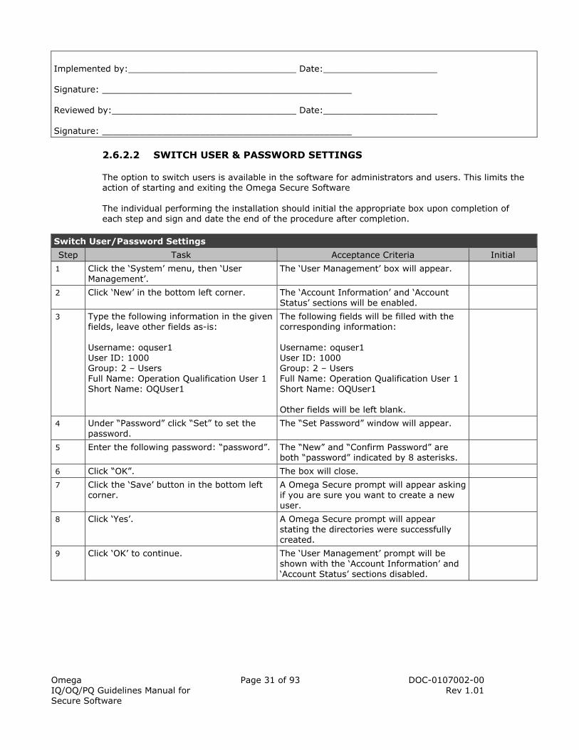
2.6.2.2 SWITCH USER & PASSWORD SETTINGS
The option to switch users is available in the software for administrators and users. This limits the action of starting and exiting the Omega Secure Software The individual performing the installation should initial the appropriate box upon completion of each step and sign and date the end of the procedure after completion.
Switch User/Password Settings
Step Task Acceptance Criteria Initial
1 Click the ‘System’ menu, then ‘User Management’.
The ‘User Management’ box will appear.
2 Click ‘New’ in the bottom left corner. The ‘Account Information’ and ‘Account Status’ sections will be enabled.
3 Type the following information in the given fields, leave other fields as-is: Username: oquser1 User ID: 1000 Group: 2 – Users Full Name: Operation Qualification User 1 Short Name: OQUser1
The following fields will be filled with the corresponding information: Username: oquser1 User ID: 1000 Group: 2 – Users Full Name: Operation Qualification User 1 Short Name: OQUser1 Other fields will be left blank.
4 Under “Password” click “Set” to set the password.
The “Set Password” window will appear.
5 Enter the following password: “password”. The “New” and “Confirm Password” are both “password” indicated by 8 asterisks.
6 Click “OK”. The box will close.
7 Click the ‘Save’ button in the bottom left corner.
A Omega Secure prompt will appear asking if you are sure you want to create a new user.
8 Click ‘Yes’. A Omega Secure prompt will appear stating the directories were successfully created.
9 Click ‘OK’ to continue. The ‘User Management’ prompt will be shown with the ‘Account Information’ and ‘Account Status’ sections disabled.

Omega IQ/OQ/PQ Guidelines Manual for Secure Software
Page 32 of 93 DOC-0107002-00 Rev 1.01
10 Repeat steps #2 through #9 to create a new user with the following information: Username: oquser2 User ID: 1001 Group: 2 – Users Full Name: Operation Qualification User 2 Short Name: OQUser2 The above test user will be used in the procedures in this IQ/OQ/PQ manual.
A new user will be created with the following information: Username: oquser2 User ID: 1001 Group: 2 – Users Full Name: Operation Qualification User 2 Short Name: OQUser2
11 Under “Password” click “Set” to set the password.
The “Set Password” window will appear.
12 Enter the following password: “password”. The “New” and “Confirm Password” are both “password” indicated by 8 asterisks.
13 Click “OK” to continue. The user is returned to the “User Management” window.
14 Click “Save” to save changes. The new user account information is saved.
15 Click “Yes” to continue. A message will appear indicating that user directories were successfully created.
16 Click ‘OK’ in the ‘User Management’ prompt.
The ‘User Management’ prompt will close.
17 Click the ‘System’ menu, then ‘Switch User’.
The Omega Switch User prompt will appear.
18 Type in the following information: Username: oquser1 Password: password
The fields in the Omega Switch User prompt read as follows: Username: oquser1 Password: password
19 Click ‘Switch User’. A Omega Secure prompt will appear stating that the password must be changed before continuing.
20 Click ‘OK’ to continue. The ‘Change Password’ prompt will appear with ‘oquser1’ as the user name.
21 Enter the old password in the ‘Old Password’ field. To test the Password settings, enter and confirm a new password that is less than six characters long. Click ‘OK’ to continue.
A prompt will appear with the message: ‘Password must be at least 6 characters long!’
22 Click ‘OK’ to continue. The ‘Change Password’ prompt will appear.
23 Enter and confirm a new password that is more than 15 character’s long. Click ‘OK’ to continue.
A prompt will appear with the message: ‘Password cannot be greater than 15 characters long!’
24 Click ‘OK’ to continue. The ‘Change Password’ prompt will appear.
25 To test the password complexity of the Security Settings test, enter and confirm ‘password’ as the new password. Click ‘OK’ to continue.
A prompt will appear stating: ‘Password must contain mixed case!’

Omega IQ/OQ/PQ Guidelines Manual for Secure Software
Page 33 of 93 DOC-0107002-00 Rev 1.01
26 Click ‘OK’ to continue. The prompt will close.
27 Enter and confirm ‘Password’ as the new password. Click ‘OK’ to continue.
A prompt will appear stating: ‘Password must contain both alpha and numeric characters!’
28 Click ‘OK’ to continue. The prompt will close.
29 Enter and confirm ‘Password2’ as the new password. Click ‘OK’ to continue.
A prompt will appear stating: ‘Password must contain at least one special character!’
30 Click ‘OK’ to continue. The prompt will close.
31 Enter the old password in the “Old Password” field. Enter and confirm ‘Password2!’ as the new password. Click ‘OK’ to continue.
A prompt will appear with the message: ‘Password changed successfully’.
32 Click ‘OK’ to continue. The user will be logged into the Omega Secure software.
Summary This completes the Switch User/Password settings section of the Security Settings Verification of the OQ procedure.
Notes
Implemented by:___________________________________ Date:_________________ Signature: ______________________________________________ Reviewed by:_____________________________________ Date:__________________ Signature: ______________________________________________
2.6.2.3 INVALID LOGIN THRESHOLD/LOCKOUT DURATION
Invalid Login Threshold/Lockout Duration
Step Task Acceptance Criteria Initial
1 Click ‘System’ menu, then ‘Switch User’. The ‘Omega Secure Switch User’ prompt will appear.
2 Enter the administrative user as the user name and enter an incorrect password. Click ‘Switch User’.
A prompt will appear stating the ‘Password is incorrect’.
3 Click ‘OK’ to continue. The prompt will close.
4 Enter the administrative user as the user name and enter an incorrect password. Click ‘Switch User’.
A prompt will appear stating the ‘Password is incorrect’.

Omega IQ/OQ/PQ Guidelines Manual for Secure Software
Page 34 of 93 DOC-0107002-00 Rev 1.01
5 Click ‘OK’ to continue. The following prompt will appear: ‘The software will be locked after the next invalid login attempt for 1 minute. To avoid being locked out of the software, be sure that the next login attempt is valid’.
6 Enter the administrative user as the user name and enter an incorrect password. Click ‘Switch User’.
A prompt will appear stating the ‘Password is incorrect’
7 Click ‘OK’ to continue. A prompt with the following message will appear: ‘The maximum number of failed login attempts has been exceeded! The software will be locked out until [Today’s Date], [Time in 1 minute]’. Only the “Cancel” button is active until the specified time has elapsed.
8 Click ‘OK’ to continue. The prompt will close. The ‘Omega Secure Unlock Software’ prompt will be shown and disabled.
9 To test the ‘Lockout Duration’ time box, verify that the waiting time before the next login is one minute.
The ‘Omega Secure Unlock Software’ prompt will be active and the username field reads ‘oquser1’.
10 Login as the administrative user. Click ‘Unlock’.
The user will be logged into the Omega Secure software.
Summary This completes the Invalid Login Threshold/Lockout Duration section of the Security Settings Verification of the OQ procedure.
Notes
Implemented by:_________________________________ Date:___________________ Signature: ______________________________________________ Reviewed by:____________________________________ Date:___________________ Signature: ______________________________________________

Omega IQ/OQ/PQ Guidelines Manual for Secure Software
Page 35 of 93 DOC-0107002-00 Rev 1.01
2.6.2.4 ENABLE CONSOLE LOCK/INACTIVITY DURATION
Enable Console Lock/Inactivity Duration
Step Task Acceptance Criteria Initial
1 To test ‘Enable Console Lock’ and the ‘Inactivity Duration’ time box, let the system idle for five minutes. Note. Do not move the mouse or press any key on keyboard.
A prompt will appear with the message: ‘The software is in use and has been locked due to inactivity’.
2 Click ‘OK’ to continue. The ‘Omega Secure Unlock Software’ box will appear.
3 Login as ‘oquser1’. Click ‘OK’ to continue.
The following prompt will appear: ‘The software is locked. Only [administrative users full name] (administrative user) or an administrator can unlock the software’.
4 Click ‘OK’ to continue. The prompt will close.
5 Login as the administrative user.
The user will be logged into the Omega Secure software.
6 At this time the system administrator should define and input the desired security settings based on the end users needs. Record the settings the ‘Workstation Configuration Record: Security Settings’ form template
The security settings for the company have been entered by the administrator.
Summary This completes the Enable Console Lock/Inactivity Duration section of the Security Settings Verification of the OQ procedure.
Notes
Implemented by:_________________________________ Date: ___________________ Signature: ______________________________________________ Reviewed by:____________________________________ Date:___________________ Signature: ______________________________________________
The following sections are recommended for testing at the time they would occur in the future (dependent on user’s settings):
• Maximum length of audit trail (in records) • Maximum file life of audit trail (in days) • Password expiration interval • Password warning interval • Password history length
This completes the Security Settings Verification of the OQ Procedure.

Omega IQ/OQ/PQ Guidelines Manual for Secure Software
Page 36 of 93 DOC-0107002-00 Rev 1.01
2.7 OMEGA SECURE SYSTEM PREFERENCES
The Omega Secure System allows the user to set preferences for how the data is viewed in the software. When data is downloaded, it is shown in a standard form. This section will customize how the data is presented. This section discusses the preferences most pertinent to the user. Refer to the Omega Data Logger and Secure Software Operating Manual for instructions on the functions of each tab. At the completion of the IQ/OQ/PQ, the administrator should enter the desired preferences for the software and document them in the Workstation Configuration Record: System Preferences. The following implemented features will be tested throughout the remainder of this document. The individual performing the installation should initial the appropriate box upon completion of each step and sign and date the end of the procedure after completion.
Omega Secure System Preferences
Step Task Acceptance Criteria Initial
1 Click the ‘System’ menu, then ‘Preferences’.
The ‘Preferences’ box will appear.
2 Verify there are six tabs in the ‘Preferences’ box: ‘File’ ‘Communications’ ‘Display’ ‘Data’ ‘Graph’ ‘Calculations’
There will be six tabs in the ‘Preferences’ box: ‘File’ ‘Communications’ ‘Display’ ‘Data’ ‘Graph’ ‘Calculations’
3 Verify the following buttons are located at the bottom of the ‘Preferences’ window: ‘Default’ ‘Cancel’ ‘OK’
The following buttons will be located at the bottom of the ‘Preferences’ window: ‘Default’ ‘Cancel’ ‘OK’
4 Verify in the ‘File’ tab there are the following options: ‘Default Log File Location’ ‘Default Data File Type’
In the ‘File’ tab, there are the following options: ‘Default Log File Location’ ‘Default Data File Type’
5 Select the ‘Communications’ tab. Verify the tab contains the following options: ‘Autoconfigure Comm Port’ ‘Autoconfigure Baud Rate’ ‘Communications Redundancy’ ‘Communications Timeout’
The ‘Communications’ tab will contain the following options: ‘Autoconfigure Comm Port’ ‘Autoconfigure Baud Rate’ ‘Communications Redundancy’ ‘Communications Timeout’
6 Select the ‘Display’ tab. Verify there are three options: ‘Use 24H Time Format’ ‘Use UTC Standard Time’ ‘Use UTC Abbreviation’
The ‘Display’ tab will contain the following information: ‘Use 24H Time Format’ ‘Use UTC Standard Time’ ‘Use UTC Abbreviation’
7 In the bottom left corner of the software, verify that the date and time are shown in the following format: M DD, YYYY [HH]: [MM]: [SS]
In the bottom left corner of the software, the date and time will be shown in the following format: M DD, YYYY [HH]: [MM]: [SS]

Omega IQ/OQ/PQ Guidelines Manual for Secure Software
Page 37 of 93 DOC-0107002-00 Rev 1.01
8 Check the ‘Use 24H Time Format’ box. The ‘Use 24H Time Format’ box will be checked off.
9 In the bottom left corner of the software, verify that the date and time have changed to be shown in the following format: DD M, YYYY [HH]: [MM]: [SS]
In the bottom left corner of the software, the date and time will be shown in the following format: DD M, YYYY [HH]: [MM]: [SS]
10 Uncheck the ‘Use 24H Time Format’ box. The ‘Use 24H Time Format’ box will be unchecked.
11 Click the ‘Data’ tab. Verify the ‘Title Preferences’ section contains the following information: ‘Device Type’ ‘Device Serial Number’ ‘Device ID’ ‘Download Date’ ‘Download Time’ ‘Prompt for Title’
The ‘Title Preferences’ section will contain the following information: ‘Device Type’ ‘Device Serial Number’ ‘Device ID’ ‘Download Date’ ‘Download Time’ ‘Prompt for Title’
12 Check the following boxes: ‘Device Type’ ‘Device Serial Number’ ‘Device ID’ ‘Download Data’ ‘Download Time’ The checked information will be the title of the graph upon download. The graph title can be changed manually.
The following boxes will have checkmarks beside them: ‘Device Type’ ‘Device Serial Number’ ‘Device ID’ ‘Download Data’ ‘Download Time’
13 Verify the following information is also in the ‘Data’ tab: ‘Unit Preferences’ ‘Select Unit Type’ ‘Select Preferred Units’ ‘Maximum Value’ (inactive) ‘Minimum Value’ (inactive) ‘Automatically Update Units’ ‘Apply units to all open data’
The following information is also contained in the ‘Data’ tab: ‘Unit Preferences’ ‘Select Unit Type’ ‘Select Preferred Units’ ‘Maximum Value’ (inactive) ‘Minimum Value’ (inactive) ‘Automatically Update Units’ ‘Apply units to all open data’
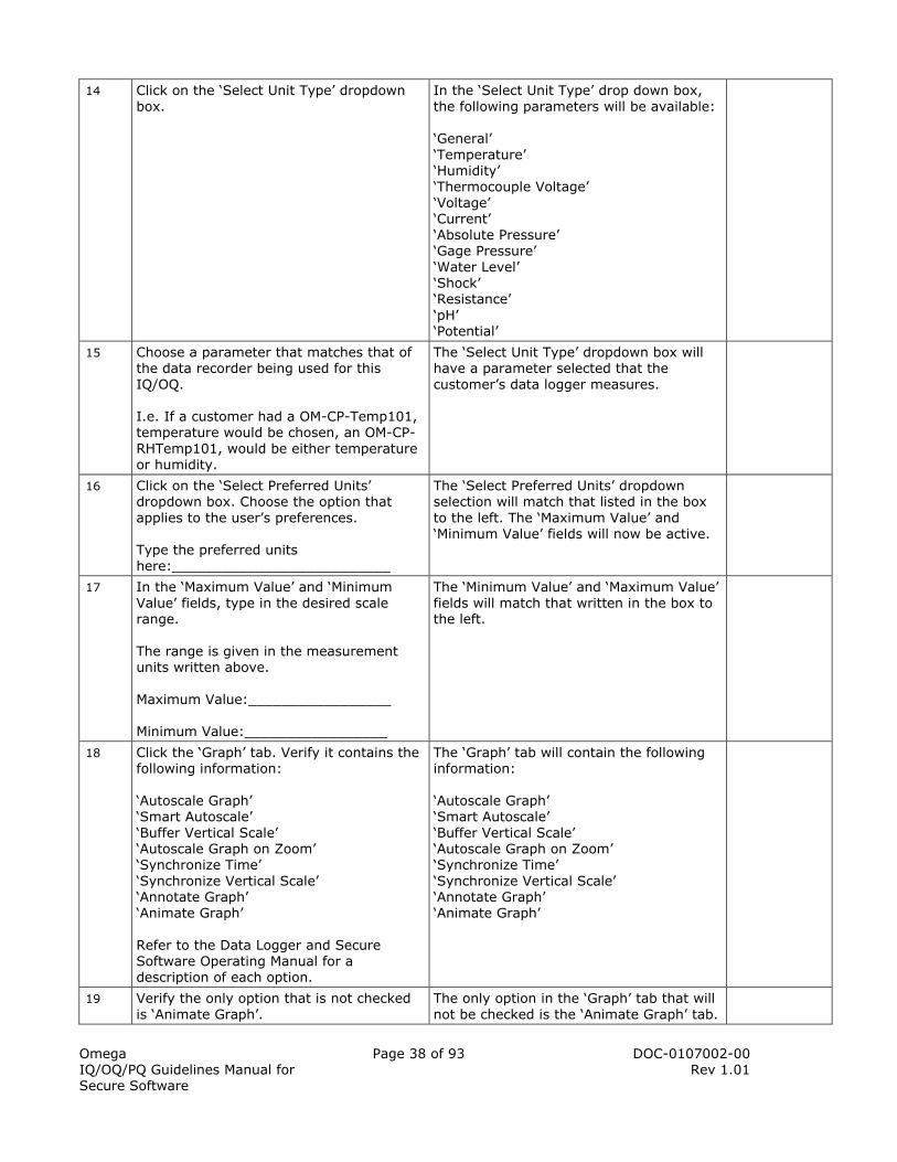
Omega IQ/OQ/PQ Guidelines Manual for Secure Software
Page 38 of 93 DOC-0107002-00 Rev 1.01
14 Click on the ‘Select Unit Type’ dropdown box.
In the ‘Select Unit Type’ drop down box, the following parameters will be available: ‘General’ ‘Temperature’ ‘Humidity’ ‘Thermocouple Voltage’ ‘Voltage’ ‘Current’ ‘Absolute Pressure’ ‘Gage Pressure’ ‘Water Level’ ‘Shock’ ‘Resistance’ ‘pH’ ‘Potential’
15 Choose a parameter that matches that of the data recorder being used for this IQ/OQ. I.e. If a customer had a OM-CP-Temp101, temperature would be chosen, an OM-CP-RHTemp101, would be either temperature or humidity.
The ‘Select Unit Type’ dropdown box will have a parameter selected that the customer’s data logger measures.
16 Click on the ‘Select Preferred Units’ dropdown box. Choose the option that applies to the user’s preferences. Type the preferred units here:__________________________
The ‘Select Preferred Units’ dropdown selection will match that listed in the box to the left. The ‘Maximum Value’ and ‘Minimum Value’ fields will now be active.
17 In the ‘Maximum Value’ and ‘Minimum Value’ fields, type in the desired scale range. The range is given in the measurement units written above. Maximum Value:_________________ Minimum Value:_________________
The ‘Minimum Value’ and ‘Maximum Value’ fields will match that written in the box to the left.
18 Click the ‘Graph’ tab. Verify it contains the following information: ‘Autoscale Graph’ ‘Smart Autoscale’ ‘Buffer Vertical Scale’ ‘Autoscale Graph on Zoom’ ‘Synchronize Time’ ‘Synchronize Vertical Scale’ ‘Annotate Graph’ ‘Animate Graph’ Refer to the Data Logger and Secure Software Operating Manual for a description of each option.
The ‘Graph’ tab will contain the following information: ‘Autoscale Graph’ ‘Smart Autoscale’ ‘Buffer Vertical Scale’ ‘Autoscale Graph on Zoom’ ‘Synchronize Time’ ‘Synchronize Vertical Scale’ ‘Annotate Graph’ ‘Animate Graph’
19 Verify the only option that is not checked is ‘Animate Graph’.
The only option in the ‘Graph’ tab that will not be checked is the ‘Animate Graph’ tab.
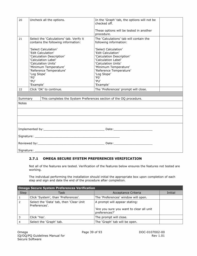
Omega IQ/OQ/PQ Guidelines Manual for Secure Software
Page 39 of 93 DOC-0107002-00 Rev 1.01
20 Uncheck all the options. In the ‘Graph’ tab, the options will not be checked off. These options will be tested in another procedure.
21 Select the ‘Calculations’ tab. Verify it contains the following information: ‘Select Calculation’ ‘Edit Calculation’ ‘Calculation Description’ ‘Calculation Label’ ‘Calculation Units’ ‘Minimum Temperature’ ‘Reference Temperature’ ‘Log Slope’ ‘F0’ ‘PU’ ‘Example’
The ‘Calculations’ tab will contain the following information: ‘Select Calculation’ ‘Edit Calculation’ ‘Calculation Description’ ‘Calculation Label’ ‘Calculation Units’ ‘Minimum Temperature’ ‘Reference Temperature’ ‘Log Slope’ ‘F0’ ‘PU’ ‘Example’
22 Click ‘OK’ to continue. The ‘Preferences’ prompt will close.
Summary This completes the System Preferences section of the OQ procedure.
Notes
Implemented by:_________________________________ Date:_____________________ Signature: ______________________________________________ Reviewed by:____________________________________ Date:_____________________ Signature: ______________________________________________
2.7.1 OMEGA SECURE SYSTEM PREFERENCES VERIFICATION
Not all of the features are tested. Verification of the features below ensures the features not tested are working. The individual performing the installation should initial the appropriate box upon completion of each step and sign and date the end of the procedure after completion.
Omega Secure System Preferences Verification
Step Task Acceptance Criteria Initial
1 Click ‘System’, than ‘Preferences’. The ‘Preferences’ window will open.
2 Select the ‘Data’ tab, then ‘Clear Unit Preferences’.
A prompt will appear stating: ‘Are you sure you want to clear all unit preferences?’
3 Click ‘Yes’. The prompt will close.
4 Select the ‘Graph’ tab. The ‘Graph’ tab will be open.

Omega IQ/OQ/PQ Guidelines Manual for Secure Software
Page 40 of 93 DOC-0107002-00 Rev 1.01
5 Check ‘Autoscale Graph’. This option sets the graph scale so that it matches the minimum and maximum values taken from the device.
The ‘Autoscale Graph’ option will be checked.
6 Check ‘Smart Autoscale’. This option rounds the vertical scale to a hundredth of a decimal point. If the option is off, they are rounded to the thousandth.
The ‘Smart Autoscale’ option will be checked.
7 Check the ‘Autoscale Graph on Zoom’ option. This option scales the graph when zooming in using the horizontal zoom.
The ‘Autoscale Graph on Zoom’ option will be checked.
8 Check the ‘Annotate Graph’ option. This option will display the annotations on the graph.
The ‘Annotate Graph’ option will be checked.
9 Click ‘OK’. The ‘Preferences’ window will close.
10 Click the ‘Device’ menu, ‘Start Device’. A prompt will appear stating: ‘This command will clear all readings and reset the device. Are you sure you want to continue?’
11 Click ‘Yes’. The ‘Start Device’ box will appear.
12 Set the following parameters: Start Method: Start Now Reading Rate: fastest available Click ‘Start’.
A box will appear that reads, ‘Processing, please wait’ and then a box will appear that states “Device Started”.
13 Click the ‘Device’ menu, then ‘Read Device Data’.
A graph will appear on the screen.
14 Verify the title of the graph, contains the following information for the device: ‘Device Type’ ‘Device Serial Number’ ‘Device ID’ ‘Download Date’ ‘Download Time’
The title of the graph will contain this device information: ‘Device Type’ ‘Device Serial Number’ ‘Device ID’ ‘Download Date’ ‘Download Time’
15 Verify that the vertical axis minimum and maximum are almost the same as the high and low measurements read by the data logger.
The vertical axis minimum and maximum will be almost the same as the high and low measurements read by the data logger.
16 Verify the vertical axis reads in hundredths of a decimal or more.
The vertical axis will read in hundredths of a decimal or more. Example: XX.XX or XX.X is acceptable.
17 Click the ‘Graph’ menu, ‘Select Graph Tool’, ‘Horizontal Zoom’.
When the cursor is over the graph, it will be in the form of a magnifying glass with a horizontal line below it and a + symbol.

Omega IQ/OQ/PQ Guidelines Manual for Secure Software
Page 41 of 93 DOC-0107002-00 Rev 1.01
18 Click and drag the cursor over a section of the data.
The graph will zoom in to show the portion of the data selected.
19 Verify the vertical axis scale is very close to the minimum and maximum data points displayed on the graph. To check this, click “Graph” then “Select Graph Tool” then “Cursor”. Click the lower and upper extremes in the graph to verify this.
The vertical axis scale will be very close to the minimum and maximum data points displayed on the graph.
20 Verify the vertical axis reads in hundredths of a decimal or more. Example: XX.XX or XX.X is acceptable.
The vertical axis will read in hundredths of a decimal or more.
21 Click the ‘Graph’ menu, ‘Select Graph Tool’, ‘Cancel Zoom’.
The graph will show the entire dataset.
22 Click the ‘Graph’ menu, ‘Select Graph Tool’, ‘Cursor’.
The cursor will be in the form of an arrow.
23 Select a data point. A cross hair will be shown on the selected data point.
24 Verify in the upper left corner, information is listed about the selected data point.
Information for the selected data point will be shown in the upper left corner of the graph.
25 Click the ‘Graph’ menu, then ‘Annotate Data’.
A prompt will appear asking for an annotation for the selected data point.
26 Type the word ‘Test’ into the field and click ‘OK’.
The word ‘Test’ will be written in the field and when OK is selected, the prompt will close.
27 Verify in the upper left hand corner of the graph the annotation is written, along with the other information about the data point.
The annotation for the data point will be noted in the upper left hand corner of the graph.
28 Verify the annotation is written on the graph with a line pointing to the data point.
Now that the ‘Annotate Data’ option is checked, the annotations made will also appear on the graph itself. Note: If there are multiple parameters displayed on the graph, the annotation will be written the same reading on each graphed line.
29 Click the ‘X’ button beside the ‘Data Set Dropdown Box’.
A box will appear stating: ‘This dataset has been modified. Would you like to save it?’
30 Click ‘Don’t Save’. The graph will close.
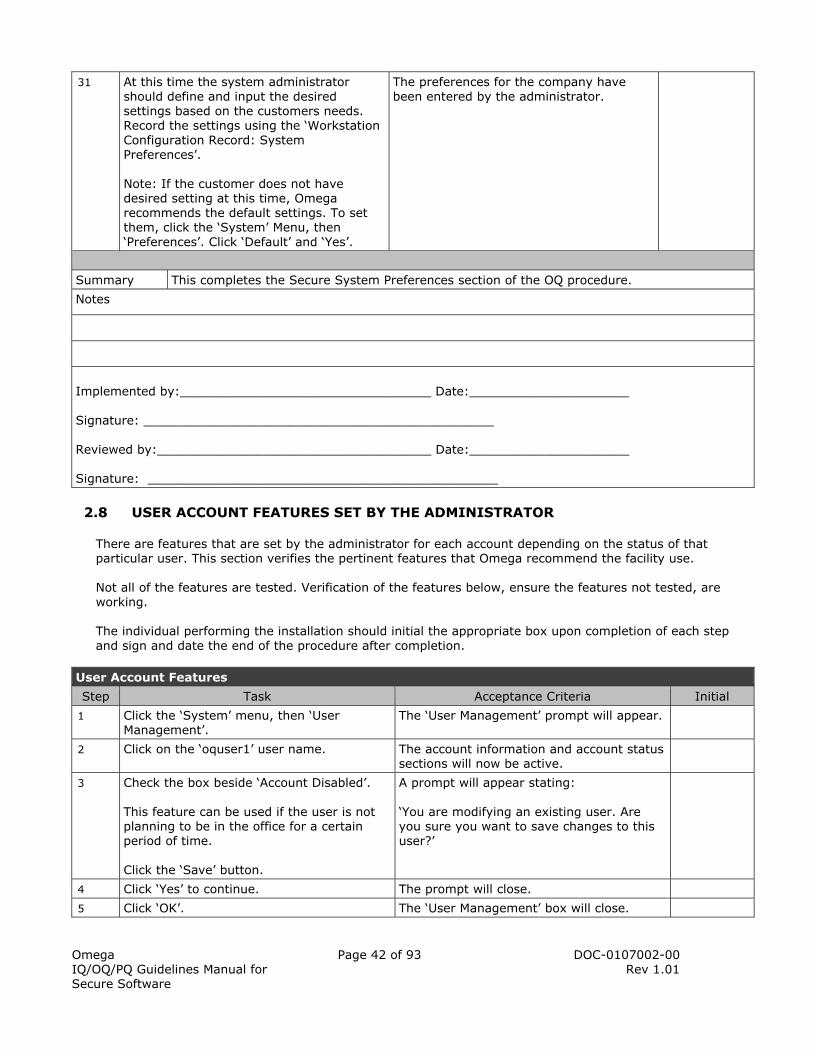
Omega IQ/OQ/PQ Guidelines Manual for Secure Software
Page 42 of 93 DOC-0107002-00 Rev 1.01
31 At this time the system administrator should define and input the desired settings based on the customers needs. Record the settings using the ‘Workstation Configuration Record: System Preferences’. Note: If the customer does not have desired setting at this time, Omega recommends the default settings. To set them, click the ‘System’ Menu, then ‘Preferences’. Click ‘Default’ and ‘Yes’.
The preferences for the company have been entered by the administrator.
Summary This completes the Secure System Preferences section of the OQ procedure.
Notes
Implemented by:_________________________________ Date:_____________________ Signature: ______________________________________________ Reviewed by:____________________________________ Date:_____________________ Signature: ______________________________________________
2.8 USER ACCOUNT FEATURES SET BY THE ADMINISTRATOR
There are features that are set by the administrator for each account depending on the status of that particular user. This section verifies the pertinent features that Omega recommend the facility use. Not all of the features are tested. Verification of the features below, ensure the features not tested, are working. The individual performing the installation should initial the appropriate box upon completion of each step and sign and date the end of the procedure after completion.
User Account Features
Step Task Acceptance Criteria Initial
1 Click the ‘System’ menu, then ‘User Management’.
The ‘User Management’ prompt will appear.
2 Click on the ‘oquser1’ user name. The account information and account status sections will now be active.
3 Check the box beside ‘Account Disabled’. This feature can be used if the user is not planning to be in the office for a certain period of time. Click the ‘Save’ button.
A prompt will appear stating: ‘You are modifying an existing user. Are you sure you want to save changes to this user?’
4 Click ‘Yes’ to continue. The prompt will close.
5 Click ‘OK’. The ‘User Management’ box will close.

Omega IQ/OQ/PQ Guidelines Manual for Secure Software
Page 43 of 93 DOC-0107002-00 Rev 1.01
6 Click the ‘System’ menu, then ‘Switch User’. The ‘Omega Secure Switch User’ prompt will appear.
7 Login ‘oquser1’. Click ‘Switch User’.
A box will appear with the message: ‘User account (oquser1) has been disabled. Cannot continue with login’.
8 Click ‘OK’ to continue. The prompt will close.
9 Login as the administrative user and open the ‘User Management’ screen, click on ‘oquser1’ user name.
The administrator will be logged in and able to edit the settings for ‘oquser1’ account.
10 Uncheck the ‘Account Disabled’ box. Click the ‘Save’ button.
A prompt will appear stating: ‘You are modifying an existing user. Are you sure you want to save changes to this user?’
11 Click ‘Yes’ to continue. The prompt will close.
12 Click ‘OK’. The ‘User Management’ box will close.
13 Click the ‘System’ menu, then ‘Switch User’. The ‘Omega Secure Switch User’ prompt will appear.
14 Login as username ‘oquser1’. The user will be able to login to the Omega Secure software.
15 Click the ‘System’ menu, then ‘Switch User’. The ‘Omega Secure Switch User’ prompt will appear.
16 Login as the administrative user. Open the ‘User Management’ screen, click on ‘oquser1’ user name.
The administrator will be logged in and able to edit the settings for ‘oquser1’ account.
17 Check the ‘Password Change Required’ box. Click the ‘Save’ button.
A prompt will appear stating: ‘You are modifying an existing user. Are you sure you want to save changes to this user?’
18 Click ‘Yes’ to continue. Close the ‘User Management’ box. Switch User’s and login as ‘oquser1’.
A prompt will appear stating: ‘Your password must be changed before continuing’.
19 Click ‘OK’ to continue. The ‘Change Password’ prompt will appear.
20 Enter the old password and change the new password to: ‘Password1@’.
A prompt will appear stating: ‘Password Changed Successfully’.
21 Switch users and login as the administrator. Open the ‘User Management’ prompt and select ‘oquser1’.
The settings for ‘oquser1’ will be editable and the ‘Password Change Required’ box will be unchecked.
22 Check the ‘Account Terminated’ box. Click the ‘Save’ button.
A prompt will appear stating: ‘You are modifying an existing user. Are you sure you want to save changes to this user?’
23 Click ‘Yes’ to continue. A prompt will appear with the message: ‘You are about to mark this user account as terminated. You will not be able to undo this action. Are you sure you want to continue?’
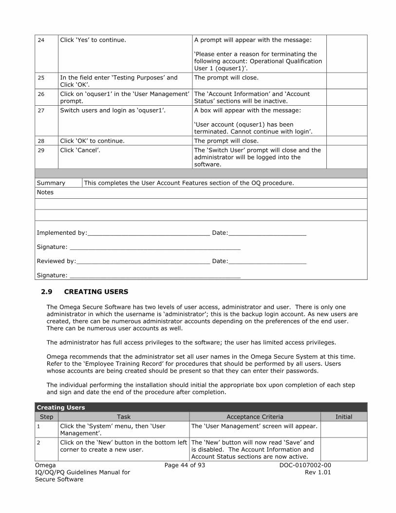
Omega IQ/OQ/PQ Guidelines Manual for Secure Software
Page 44 of 93 DOC-0107002-00 Rev 1.01
24 Click ‘Yes’ to continue. A prompt will appear with the message: ‘Please enter a reason for terminating the following account: Operational Qualification User 1 (oquser1)’.
25 In the field enter ‘Testing Purposes’ and Click ‘OK’.
The prompt will close.
26 Click on ‘oquser1’ in the ‘User Management’ prompt.
The ‘Account Information’ and ‘Account Status’ sections will be inactive.
27 Switch users and login as ‘oquser1’. A box will appear with the message: ‘User account (oquser1) has been terminated. Cannot continue with login’.
28 Click ‘OK’ to continue. The prompt will close.
29 Click ‘Cancel’. The ‘Switch User’ prompt will close and the administrator will be logged into the software.
Summary This completes the User Account Features section of the OQ procedure.
Notes
Implemented by:_________________________________ Date:_____________________ Signature: ______________________________________________ Reviewed by:____________________________________ Date:_____________________ Signature: ______________________________________________
2.9 CREATING USERS
The Omega Secure Software has two levels of user access, administrator and user. There is only one administrator in which the username is ‘administrator’; this is the backup login account. As new users are created, there can be numerous administrator accounts depending on the preferences of the end user. There can be numerous user accounts as well. The administrator has full access privileges to the software; the user has limited access privileges.
Omega recommends that the administrator set all user names in the Omega Secure System at this time. Refer to the ‘Employee Training Record’ for procedures that should be performed by all users. Users whose accounts are being created should be present so that they can enter their passwords. The individual performing the installation should initial the appropriate box upon completion of each step and sign and date the end of the procedure after completion.
Creating Users
Step Task Acceptance Criteria Initial
1 Click the ‘System’ menu, then ‘User Management’.
The ‘User Management’ screen will appear.
2 Click on the ‘New’ button in the bottom left corner to create a new user.
The ‘New’ button will now read ‘Save’ and is disabled. The Account Information and Account Status sections are now active.

Omega IQ/OQ/PQ Guidelines Manual for Secure Software
Page 45 of 93 DOC-0107002-00 Rev 1.01
3 In the ‘User Name’ field, type in the user name for the first user’s account. Omega recommends that the user name is written in lowercase letters.
The ‘User Name’ field will be filled out.
4 Verify the ‘User ID’ field is ‘3’. The ‘User ID’ field will be ‘3’.
5 Click on the ‘Group’ Dropdown box choose ‘2 – Users’.
The ‘Group’ field will read ‘2 - Users’.
6 In the ‘Full Name’ field, type in the full name of the user. Omega recommends the full name include the first name, middle initial and last name.
The ‘Full Name’ field will have the full name of the first user entered.
7 In the ‘Short Name’ field, type in a shorter version of the full name (for identity purposes). Omega recommends using the first letter of the first name and the full last name of the user.
The ‘Short Name’ field will have the short name of the user entered.
8 In the ‘Email’ field, type in the email for the user.
The ‘Email’ field will have the email of the user entered.
9 In the ‘Password’ field, click ‘Set’. The ‘Set Password’ prompt appears.
10 Have the user type and confirm their password. Click ‘OK’ to continue.
The prompt will close and the ‘Password Modified’ and ‘Password Change Required’ boxes in the ‘Account Status’ section will now be checked off and disabled. This is to ensure the security of each account.
11 Click the ‘Save’ button in the bottom left corner.
A Omega Secure prompt will appear stating ‘Are you sure you want to create a new user? You will not be able to undo this action?’
12 Click ‘Yes’ to continue. A Omega Secure prompt will appear stating ‘Successfully created user directories!’
13 Click ‘OK’ to continue. The newly created user will be listed in the ‘User Management’ screen.
14 Repeat steps #2 - #13 for each user to be created.
All required users are created at this time and documented in the ‘Workstation Account Summary: Account List’.
15 Click ‘OK’ to close the ‘User Management’ prompt.
The ‘User Management’ prompt will close.
Summary This completes the Creating Users section of the OQ procedure.
Notes

Omega IQ/OQ/PQ Guidelines Manual for Secure Software
Page 46 of 93 DOC-0107002-00 Rev 1.01
Implemented by:_________________________________ Date:_____________________ Signature: ______________________________________________ Reviewed by:____________________________________ Date:_____________________ Signature: ______________________________________________
2.10 OPERATIONAL QUALIFICATION PROCEDURE (HARDWARE)
This section details the main operating functions of the Omega data loggers and software. The following tests are outlined on the ‘Employee Training Guide’ and should be performed by all users using the Omega Secure System. Each user should login with their username to complete the procedures.
2.10.1 OMEGA DATA LOGGER FUNCTIONAL VERIFICATION
The following procedure verifies the proper function of all the Omega data loggers associated with this system. The individual performing the installation should initial the appropriate box upon completion of each step and sign and date the end of the procedure after completion.
Data Recorder Functionality
Step Task Acceptance Criteria Initial
1 Connect a Omega data logger to the interface cable.
The interface cable will be securely plugged into the data logger and the other end in the PC.
2 From the ‘Communication’ Menu click ‘Select Comm Port’
The following options are available in ‘Select Comm Port’: ‘USB1’ ‘COM1’ ‘COM2’ ‘COM3’ ‘COM4’ ‘COM5’ ‘COM6’ ‘COM7’ ‘COM8’ The USB1 option is only available if the USB drivers have been installed.
3 Select the same communications port that the interface cable is connected to. The correct communications port varies by computer. If the incorrect communications port is chosen a prompt will appear, stating: ‘Unable to open [selected port]! Invalid Port (33025)’. Choose another port until the acceptance criteria is met.
There will be a checkmark beside the correct communications port.

Omega IQ/OQ/PQ Guidelines Manual for Secure Software
Page 47 of 93 DOC-0107002-00 Rev 1.01
4 Click the ‘Communication’ Menu, then ‘Select Baud Rate’
The following options are available in ‘Select Baud Rate’: ‘600 baud’ ‘1200 baud’ ‘2400 baud’ ‘4800 baud’ ‘9600 baud’ ‘14400 baud’ ‘19200 baud’ ‘28800 baud’ ‘38400 baud’ ‘57600 baud’ ‘115200 baud’
5 Select the same baud rate that is specified on the label of the data logger connected to the interface cable.
There will be a checkmark beside the baud rate that matches that of the data logger plugged into the interface cable.
6 Click the ‘Device’ menu, then ‘Identify Device and Read Status’.
The ‘Device Status’ window will appear which displays all of the information relative to the specific device that is connected. An example of a typical device is shown in figure 5, below. If the ‘Device Status’ window does not appear, please refer to the Omega troubleshooting guide.
7 Click the ‘Print’ button. The ‘Print’ window will appear.
8 Select the correct printer and click ‘Print’. Retrieve the printout. Note. A printer must be installed for this feature to work. If not printer is installed, skip this step and document it in the notes section at the end of this procedure.
The device status information will print. The form will have the same layout as the example device status printout shown figure 6, below.
9 If a printout was generated in the previous step, verify the information contained on the report matches the device information (i.e. serial number, reading rate, start date, …) If not, skip to the next step. Document it at the end of this procedure. Note. Any printouts generated should be kept on file for verification purposes.
The generated printout will provide information specific to the data logger plugged into the interface cable.
10 In the software click the ‘Device Detail’ tab located at the top of the ‘Device Status’ window.
The ‘Device Detail’ tab will appear which displays all of the information about the measurement parameters of the data logger. An example of a typical device is shown in figure 7, below.
11 Verify that the range indicated for the device channel(s) matches the specified range for the actual device.
The information on the ‘Device Detail’ tab will be specific to the data logger plugged into the interface cable.
12 Click ‘OK’ to close the box. The ‘Device Detail’ window will close.
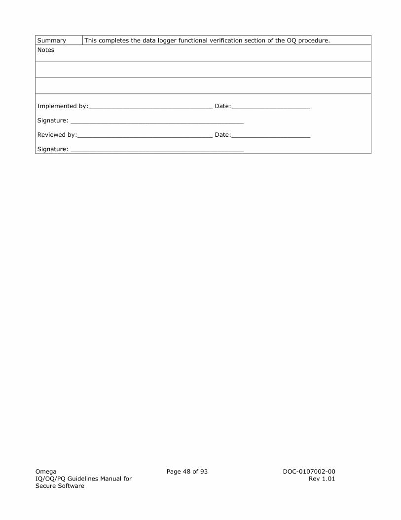
Omega IQ/OQ/PQ Guidelines Manual for Secure Software
Page 48 of 93 DOC-0107002-00 Rev 1.01
Summary This completes the data logger functional verification section of the OQ procedure.
Notes
Implemented by:_________________________________ Date:_____________________ Signature: ______________________________________________ Reviewed by:____________________________________ Date:_____________________ Signature: ______________________________________________
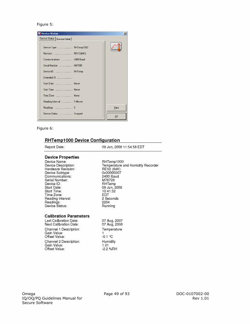
Omega IQ/OQ/PQ Guidelines Manual for Secure Software
Page 49 of 93 DOC-0107002-00 Rev 1.01
Figure 5:
Figure 6:
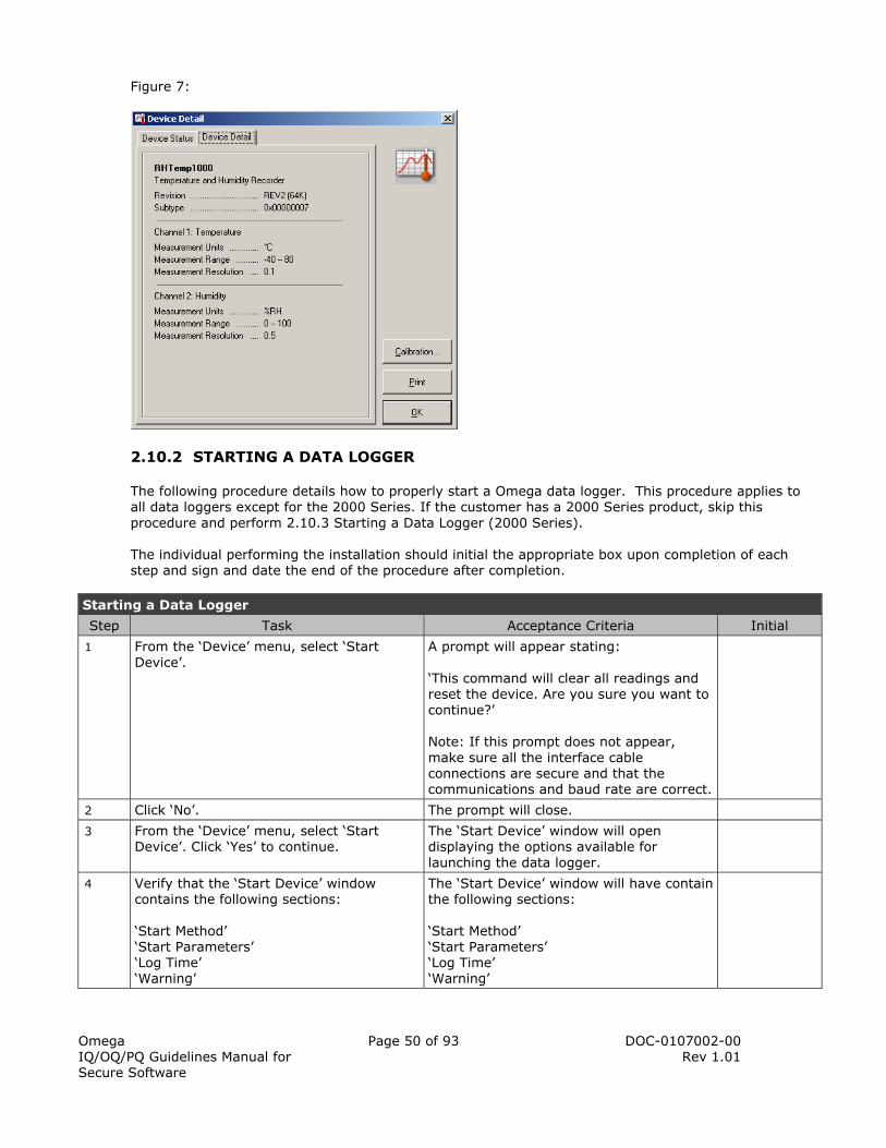
Omega IQ/OQ/PQ Guidelines Manual for Secure Software
Page 50 of 93 DOC-0107002-00 Rev 1.01
Figure 7:
2.10.2 STARTING A DATA LOGGER
The following procedure details how to properly start a Omega data logger. This procedure applies to all data loggers except for the 2000 Series. If the customer has a 2000 Series product, skip this procedure and perform 2.10.3 Starting a Data Logger (2000 Series). The individual performing the installation should initial the appropriate box upon completion of each step and sign and date the end of the procedure after completion.
Starting a Data Logger
Step Task Acceptance Criteria Initial
1 From the ‘Device’ menu, select ‘Start Device’.
A prompt will appear stating: ‘This command will clear all readings and reset the device. Are you sure you want to continue?’ Note: If this prompt does not appear, make sure all the interface cable connections are secure and that the communications and baud rate are correct.
2 Click ‘No’. The prompt will close.
3 From the ‘Device’ menu, select ‘Start Device’. Click ‘Yes’ to continue.
The ‘Start Device’ window will open displaying the options available for launching the data logger.
4 Verify that the ‘Start Device’ window contains the following sections: ‘Start Method’ ‘Start Parameters’ ‘Log Time’ ‘Warning’
The ‘Start Device’ window will have contain the following sections: ‘Start Method’ ‘Start Parameters’ ‘Log Time’ ‘Warning’

Omega IQ/OQ/PQ Guidelines Manual for Secure Software
Page 51 of 93 DOC-0107002-00 Rev 1.01
5 In the ‘Start Method’ section, verify the following options are available: ‘Start Now’ ‘Delay Start’ ‘Manual Start’ Note: The ‘Start Now’ method will launch the logger immediately. The ‘Delay Start’ method will start the logger at a time in the future that can be specified by changing the date and time in the boxes to the right of the start method option buttons. The ‘Manual Start’ method allows the user to manually start the logger by activating the pushbutton or other manual start system on the device if available. Depending on the device, the option to program a manual delay may be available. To do this, use the boxes to the right of the start method option buttons.
The ‘Start Method’ section, will have the following options: ‘Start Now’ ‘Delay Start’ ‘Manual Start’
6 In the ‘Start Method’ section, verify there are two configuration boxes that read ‘Now’.
In the ‘Start Method’ section, there will be two configuration boxes that read ‘Now’.
7 In the ‘Start Parameters’ section, verify the following options are available: ‘Device Type’ ‘Serial Number’ ‘Device ID’ ‘Extended ID’ ‘Reading Rate’ ‘Wrap Around’ All available programmable start parameters will be active for the specific device being used.
In the ‘Start Parameters’ section, the following options will be available: ‘Device Type’ ‘Serial Number’ ‘Device ID’ ‘Extended ID’ ‘Reading Rate’ ‘Wrap Around’
8 In the ‘Log Time’ section, verify the following information is shown: ‘Days’ ‘Hours’ ‘Minutes’ ‘Seconds’
In the ‘Log Time’ section, the following information will be shown: ‘Days’ ‘Hours’ ‘Minutes’ ‘Seconds’
9 At the bottom of the ‘Start Device’ window, verify that a warning is displayed about the proper usage and handling of the device battery.
At the bottom of the ‘Start Device’ window, a warning is displayed about the proper usage and handling of the device battery.

Omega IQ/OQ/PQ Guidelines Manual for Secure Software
Page 52 of 93 DOC-0107002-00 Rev 1.01
10 On the right side of the ‘Start Device’ window, verify the following buttons are located on the bottom right: ‘Cancel’ ‘Start’ Note: There may be additional options available, such as: ‘Set Password’ ‘Alarm Settings’ ‘Trigger Settings’ These options are dependent on the data logger being used.
The following buttons will be displayed on the bottom right hand side of the ‘Start Device’ window: ‘Cancel’ ‘Start’
11 Click the ‘Cancel’ button in the bottom right corner of the window. Note. The ‘Cancel’ button can be used at any time to cancel the starting of the device. If the cancel button is pressed, no settings will be programmed into the device.
The ‘Start Device’ window will close.
12 Open the ‘Start Device’ window. The ‘Start Device’ window will appear.
13 Choose the ‘Start Now’ method for starting the device.
The ‘Start Now’ option will be selected. The drop down boxes to the left of the option will both read ‘Now’.
14 The ‘Device ID’ field allows you to set a device ID into the data logger. This can be useful for identifying the data logger in a batch run, or shipment of a product. Set this field to ‘TestID’.
The ‘Device ID’ field will read ‘TestID’.
15 If available, the ‘Extended ID’ field allows you to set an extended ID into the data logger. This can be useful to add additional identification information for the data logger in a batch, run or shipment of product. Set this field to ‘Test Extended ID’, if it is available. If not, skip this step and document it at the end of this procedure.
If the option is available, the ‘Extended ID’ field will read ‘Test Extended ID’.
16 The ‘Reading Rate’ dropdown list allows you to select a reading rate for the data logger. All available reading rates for the device should be listed in the dropdown list. Click on the drop down box and select the fastest reading rate the device has available.
When the ‘Reading Rate’ drop down box is opened, the scroll bar will be at the top of the scroll and the first reading rate will be highlighted in blue. The ‘Reading Rate’ drop down box will have the fastest reading rate available to the logger selected.

Omega IQ/OQ/PQ Guidelines Manual for Secure Software
Page 53 of 93 DOC-0107002-00 Rev 1.01
17 If available, the ‘Wrap Around’ checkbox allows the user to enable device memory wrap around. This feature can be used when you want the data logger to overwrite the oldest data in memory when the logger reaches the end of memory. If this feature is unchecked, the device will stop recording when the end of memory is reached. Place a check in the ‘Wrap Around’ checkbox if this feature is available. If not, skip this step and document it at the end of this procedure.
If the option is enabled, the ‘Wrap Around’ checkbox will be checked.
18 The ‘Log Time’ section displays the device recording time required to fill the entire memory. This duration is based on the reading rate selected. Ensure that the time displayed is reasonable for the selected reading rate.
The ‘Log Time’ section will be reasonable for the selected reading rate.
19 Press the ‘Start’ button to store the new settings into the data logger.
The software will display a ‘Processing, please wait…’ window while the software communicates with the data logger. A prompt will appear stating ‘Device Started’.
20 Click ‘OK’ to continue. The prompt will close.
21 Click the ‘Device’ menu, then ‘Identify Device and Read Status’.
The ‘Device Status’ window will appear.
22 Verify that the ‘Device Status’ information at the bottom of the window reads ‘Running’.
The ‘Device Status’ information will state the data logger is running.
23 Click ‘OK’. The ‘Device Status’ box will close.
Summary This completes the Starting a Data Logger section of the OQ procedure.
Notes
Implemented by:_________________________________ Date:_____________________ Signature: ______________________________________________ Reviewed by:____________________________________ Date:_____________________ Signature: ______________________________________________
2.10.3 STARTING A DATA LOGGER (2000 SERIES)
The following procedure details how to properly start a Omega 2000 Series data logger. The individual performing the installation should initial the appropriate box upon completion of each step

Omega IQ/OQ/PQ Guidelines Manual for Secure Software
Page 54 of 93 DOC-0107002-00 Rev 1.01
and sign and date the end of the procedure after completion. If the user does not have a 2000 Series data logger, procedure 2.10.2 should be performed. The individual performing the installation should initial the appropriate box upon completion of each step and sign and date the end of the procedure after completion.
Starting a Data Logger (2000 Series)
Step Task Acceptance Criteria Initial
1 From the ‘Device’ menu, select ‘Start Device’.
A prompt will appear stating: ‘This command will clear all readings and reset the device. Are you sure you want to continue?’ Note: If this prompt does not appear, make sure all the interface cable connections are secure and that the communications and baud rate are correct.
2 Click ‘No’. The prompt will close.
3 From the ‘Device’ menu, select ‘Start Device’. Click ‘Yes’ to continue.
The ‘Start Device’ window will open displaying the options available for launching the data logger.
4 Verify that the ‘Start Device’ window contains the following sections: ‘Start Method’ ‘Stop Method’ ‘Start Parameters’ ‘Log Time’ ‘Warning’
The ‘Start Device’ window will have the following parameters: ‘Start Method’ ‘Stop Method’ ‘Start Parameters’ ‘Log Time’ ‘Warning’
5 In the ‘Start Method’ section, verify the following options are available: ‘Start Now’ ‘Delay Start’ ‘Manual Start’ Note: The ‘Start Now’ method will launch the logger immediately. The ‘Delay Start’ method will start the logger at a time in the future that can be specified by changing the date and time in the boxes to the right of the start method option buttons. The ‘Manual Start’ method allows the user to manually start the logger by activating the pushbutton or other manual start system on the device if available. Depending on the device, the option to program a manual delay may be available. To do this, use the boxes to the right of the start method option buttons.
The ‘Start Method’ section, will have the following options: ‘Start Now’ ‘Delay Start’ ‘Manual Start’
6 In the ‘Start Method’ section, verify there are two configuration boxes that read ‘Now’.
In the ‘Start Method’ section, there will be two configuration boxes that read ‘Now’.
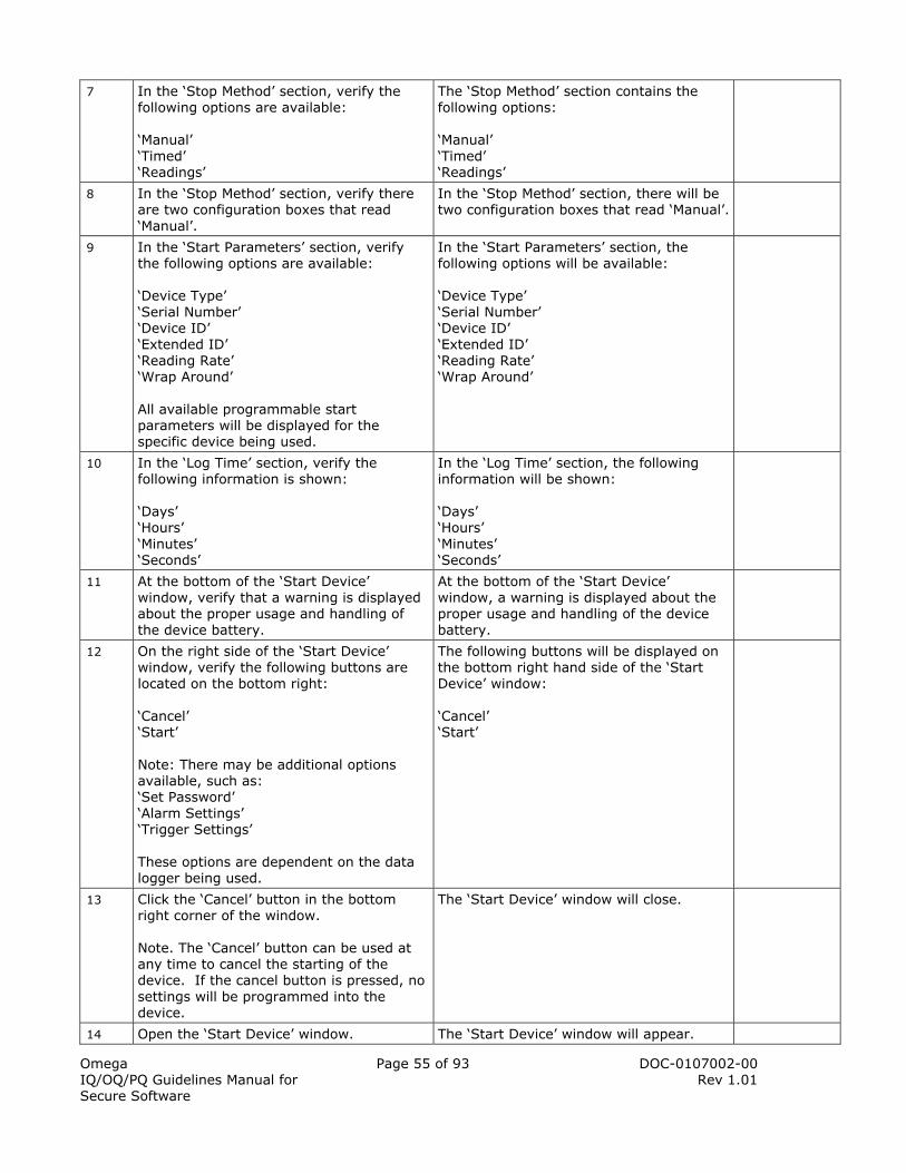
Omega IQ/OQ/PQ Guidelines Manual for Secure Software
Page 55 of 93 DOC-0107002-00 Rev 1.01
7 In the ‘Stop Method’ section, verify the following options are available: ‘Manual’ ‘Timed’ ‘Readings’
The ‘Stop Method’ section contains the following options: ‘Manual’ ‘Timed’ ‘Readings’
8 In the ‘Stop Method’ section, verify there are two configuration boxes that read ‘Manual’.
In the ‘Stop Method’ section, there will be two configuration boxes that read ‘Manual’.
9 In the ‘Start Parameters’ section, verify the following options are available: ‘Device Type’ ‘Serial Number’ ‘Device ID’ ‘Extended ID’ ‘Reading Rate’ ‘Wrap Around’ All available programmable start parameters will be displayed for the specific device being used.
In the ‘Start Parameters’ section, the following options will be available: ‘Device Type’ ‘Serial Number’ ‘Device ID’ ‘Extended ID’ ‘Reading Rate’ ‘Wrap Around’
10 In the ‘Log Time’ section, verify the following information is shown: ‘Days’ ‘Hours’ ‘Minutes’ ‘Seconds’
In the ‘Log Time’ section, the following information will be shown: ‘Days’ ‘Hours’ ‘Minutes’ ‘Seconds’
11 At the bottom of the ‘Start Device’ window, verify that a warning is displayed about the proper usage and handling of the device battery.
At the bottom of the ‘Start Device’ window, a warning is displayed about the proper usage and handling of the device battery.
12 On the right side of the ‘Start Device’ window, verify the following buttons are located on the bottom right: ‘Cancel’ ‘Start’ Note: There may be additional options available, such as: ‘Set Password’ ‘Alarm Settings’ ‘Trigger Settings’ These options are dependent on the data logger being used.
The following buttons will be displayed on the bottom right hand side of the ‘Start Device’ window: ‘Cancel’ ‘Start’
13 Click the ‘Cancel’ button in the bottom right corner of the window. Note. The ‘Cancel’ button can be used at any time to cancel the starting of the device. If the cancel button is pressed, no settings will be programmed into the device.
The ‘Start Device’ window will close.
14 Open the ‘Start Device’ window. The ‘Start Device’ window will appear.
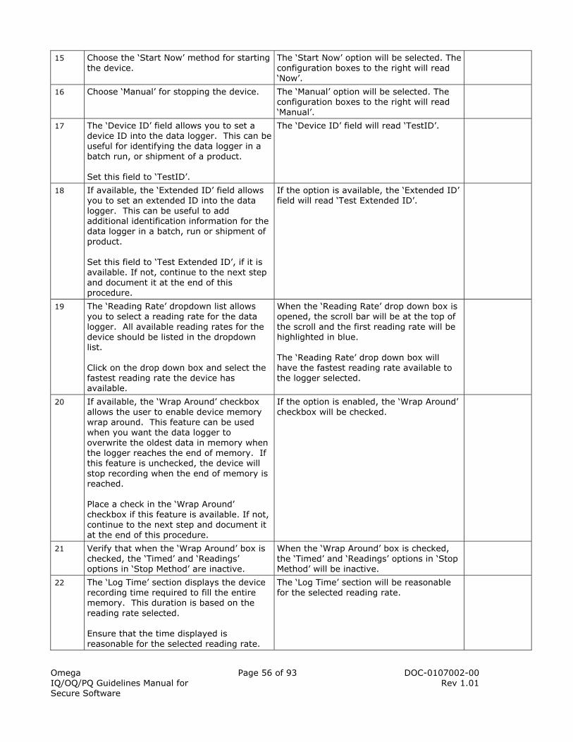
Omega IQ/OQ/PQ Guidelines Manual for Secure Software
Page 56 of 93 DOC-0107002-00 Rev 1.01
15 Choose the ‘Start Now’ method for starting the device.
The ‘Start Now’ option will be selected. The configuration boxes to the right will read ‘Now’.
16 Choose ‘Manual’ for stopping the device. The ‘Manual’ option will be selected. The configuration boxes to the right will read ‘Manual’.
17 The ‘Device ID’ field allows you to set a device ID into the data logger. This can be useful for identifying the data logger in a batch run, or shipment of a product. Set this field to ‘TestID’.
The ‘Device ID’ field will read ‘TestID’.
18 If available, the ‘Extended ID’ field allows you to set an extended ID into the data logger. This can be useful to add additional identification information for the data logger in a batch, run or shipment of product. Set this field to ‘Test Extended ID’, if it is available. If not, continue to the next step and document it at the end of this procedure.
If the option is available, the ‘Extended ID’ field will read ‘Test Extended ID’.
19 The ‘Reading Rate’ dropdown list allows you to select a reading rate for the data logger. All available reading rates for the device should be listed in the dropdown list. Click on the drop down box and select the fastest reading rate the device has available.
When the ‘Reading Rate’ drop down box is opened, the scroll bar will be at the top of the scroll and the first reading rate will be highlighted in blue. The ‘Reading Rate’ drop down box will have the fastest reading rate available to the logger selected.
20 If available, the ‘Wrap Around’ checkbox allows the user to enable device memory wrap around. This feature can be used when you want the data logger to overwrite the oldest data in memory when the logger reaches the end of memory. If this feature is unchecked, the device will stop recording when the end of memory is reached. Place a check in the ‘Wrap Around’ checkbox if this feature is available. If not, continue to the next step and document it at the end of this procedure.
If the option is enabled, the ‘Wrap Around’ checkbox will be checked.
21 Verify that when the ‘Wrap Around’ box is checked, the ‘Timed’ and ‘Readings’ options in ‘Stop Method’ are inactive.
When the ‘Wrap Around’ box is checked, the ‘Timed’ and ‘Readings’ options in ‘Stop Method’ will be inactive.
22 The ‘Log Time’ section displays the device recording time required to fill the entire memory. This duration is based on the reading rate selected. Ensure that the time displayed is reasonable for the selected reading rate.
The ‘Log Time’ section will be reasonable for the selected reading rate.

Omega IQ/OQ/PQ Guidelines Manual for Secure Software
Page 57 of 93 DOC-0107002-00 Rev 1.01
23 Press the ‘Start’ button to store the new settings into the data logger.
The software will display a ‘Processing, please wait…’ window while the software communicates with the data logger. A prompt will appear stating ‘Device Started’.
24 Click ‘OK’ to continue. The prompt will close.
25 Click the ‘Device’ menu, then ‘Identify Device and Read Status’.
The ‘Device Status’ window will appear.
26 Verify that the ‘Device Status’ information at the bottom of the window reads ‘Running’.
The ‘Device Status’ information will state the data logger is running.
27 Click ‘OK’. The ‘Device Status’ box will close.
Summary This completes the Starting a Data Logger (2000 Series) section of the OQ procedure.
Notes
Implemented by:_________________________________ Date:_____________________ Signature: ______________________________________________ Reviewed by:____________________________________ Date:_____________________ Signature: ______________________________________________
2.10.4 TRIGGER SETTINGS
Trigger settings are a useful feature when the user only wants to analyze a specific range or value of data. This is particularly useful when the process being monitoring involves transient events, or events that are variable. For example, trigger settings on a OM-CP-PRTrans1000 pressure data logger is useful when the user is trying to measure pressure spikes that are unpredictable, but does not want to collect data that does not pertain to the programmed trigger. Moreover, trigger settings are interlinked with the sampling of the device. This means that while continuously looking for a programmed trigger value (e.g. 30 PSI), the device will sample, but not write to memory any values that are not near 30 PSI. This saves the user time, by alleviating the need to look at irrelevant data. Since the programming of trigger settings requires a data logger, the user must have one present and an interface cable to complete this step. The following data loggers have the trigger setting feature:
• OM-CP-PRTrans1000 • OM-CP-PRTrans1000IS • OM-CP-TSR101 • OM-CP-SVR101
If the user does not have a data logger with trigger settings at this time, skip this test and continue. Document the reason in the notes section.
The individual performing the installation should initial the appropriate box upon completion of each step and sign and date the end of the procedure after completion.
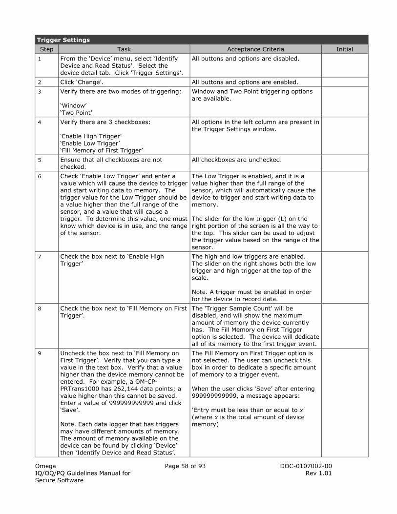
Omega IQ/OQ/PQ Guidelines Manual for Secure Software
Page 58 of 93 DOC-0107002-00 Rev 1.01
Trigger Settings
Step Task Acceptance Criteria Initial
1 From the ‘Device’ menu, select ‘Identify Device and Read Status’. Select the device detail tab. Click ‘Trigger Settings’.
All buttons and options are disabled.
2 Click ‘Change’. All buttons and options are enabled.
3 Verify there are two modes of triggering: ‘Window’ ‘Two Point’
Window and Two Point triggering options are available.
4 Verify there are 3 checkboxes: ‘Enable High Trigger’ ‘Enable Low Trigger’ ‘Fill Memory of First Trigger’
All options in the left column are present in the Trigger Settings window.
5 Ensure that all checkboxes are not checked.
All checkboxes are unchecked.
6 Check ‘Enable Low Trigger’ and enter a value which will cause the device to trigger and start writing data to memory. The trigger value for the Low Trigger should be a value higher than the full range of the sensor, and a value that will cause a trigger. To determine this value, one must know which device is in use, and the range of the sensor.
The Low Trigger is enabled, and it is a value higher than the full range of the sensor, which will automatically cause the device to trigger and start writing data to memory. The slider for the low trigger (L) on the right portion of the screen is all the way to the top. This slider can be used to adjust the trigger value based on the range of the sensor.
7 Check the box next to ‘Enable High Trigger’
The high and low triggers are enabled. The slider on the right shows both the low trigger and high trigger at the top of the scale. Note. A trigger must be enabled in order for the device to record data.
8 Check the box next to ‘Fill Memory on First Trigger’.
The ‘Trigger Sample Count’ will be disabled, and will show the maximum amount of memory the device currently has. The Fill Memory on First Trigger option is selected. The device will dedicate all of its memory to the first trigger event.
9 Uncheck the box next to ‘Fill Memory on First Trigger’. Verify that you can type a value in the text box. Verify that a value higher than the device memory cannot be entered. For example, a OM-CP-PRTrans1000 has 262,144 data points; a value higher than this cannot be saved. Enter a value of 999999999999 and click ‘Save’. Note. Each data logger that has triggers may have different amounts of memory. The amount of memory available on the device can be found by clicking ‘Device’ then ‘Identify Device and Read Status’.
The Fill Memory on First Trigger option is not selected. The user can uncheck this box in order to dedicate a specific amount of memory to a trigger event. When the user clicks ‘Save’ after entering 999999999999, a message appears: ‘Entry must be less than or equal to x’ (where x is the total amount of device memory)

Omega IQ/OQ/PQ Guidelines Manual for Secure Software
Page 59 of 93 DOC-0107002-00 Rev 1.01
10 Click ‘OK’. Enter a value of 5 into the trigger text box and click ‘Save’.
Depending on the device, a message may appear: ‘Entry must be greater than or equal to 256’ 256 is minimum trigger size.
11 Click ‘OK’. Enter a value of 300 into the trigger text box and click ‘Save’.
A message appears: ‘This command will clear all readings and reset the device. Are you sure you want to continue?’
12 Click ‘Yes’. A message appears: ‘Device Reset’.
13 Click ‘OK’. The device is processing until a message appears: ‘Trigger Settings written successfully’.
14 Click ‘OK’. The user is returned to the Trigger Settings window and all options are disabled. The trigger count is 300 and the only enabled buttons are ‘OK’ and ‘Change’.
15 Click the ‘Change’ button. Select ‘Two Point’ in the ‘Trigger Mode’ section.
The Trigger Settings window changes to display two sets of trigger settings and a pair of trigger sliders on the right. The ‘Enabled High Trigger’ has two options: ‘Start High Setpoint’ ‘Stop High Setpoint’ The ‘Enabled Low Trigger’ has two options: ‘Start Low Setpoint’ ‘Stop Low Setpoint’
16 Check ‘Enable High Trigger’. The high trigger is enabled, while the low trigger is disabled.
17 Check ‘Enable Low Trigger’. The low trigger is enabled, while the high trigger is disabled.
18 Check ‘Enable High Trigger’. Both low and high triggers are enabled.
19 Click the ‘Save’ button. A message appears: ‘Trigger Settings Written Successfully’.
20 Click ‘OK’ to continue. Click the ‘Change’ button. Select ‘Window’ from the trigger mode section.
The device is set back to the default trigger mode. Note. To read about the differences between the Window and Two Point mode, please refer to the next section.
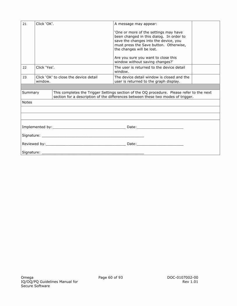
Omega IQ/OQ/PQ Guidelines Manual for Secure Software
Page 60 of 93 DOC-0107002-00 Rev 1.01
21 Click ‘OK’. A message may appear: ‘One or more of the settings may have been changed in this dialog. In order to save the changes into the device, you must press the Save button. Otherwise, the changes will be lost. Are you sure you want to close this window without saving changes?’
22 Click ‘Yes’. The user is returned to the device detail window.
23 Click ‘OK’ to close the device detail window.
The device detail window is closed and the user is returned to the graph display.
Summary This completes the Trigger Settings section of the OQ procedure. Please refer to the next section for a description of the differences between these two modes of trigger.
Notes
Implemented by:_________________________________ Date:_____________________ Signature: ______________________________________________ Reviewed by:____________________________________ Date:_____________________ Signature: ______________________________________________

Omega IQ/OQ/PQ Guidelines Manual for Secure Software
Page 61 of 93 DOC-0107002-00 Rev 1.01
2.10.5 WINDOW TRIGGER VS TWO POINT TRIGGER EXPLAINED
This is not a test procedure, but rather an explanation of the differences between the Window Trigger and Two Point trigger mode. This section only pertains to data loggers that have ‘Triggers’. If the data logger being tested does not have a trigger, please continue to the next test. In Window Mode, the user must enable the high and/or low trigger in order for the device to record data. A high trigger level will start an event when the value (e.g. pressure, acceleration) falls below the chosen level. After an event is triggered, the data logger will take a number of samples equal to the number set in the Sample Count. If the user disables either the High or Low trigger levels the device will not trigger at all in the disabled region. If both trigger levels are set (high and low), then the high cannot be below the low level. There is also software determined minimum difference between the levels. The software will warn the user if the levels are too close. In Two Point Mode, the user can set start and stop trigger levels for High Level and Low Level. In this mode, the number of samples taken is determined by the time the pressure spends above the high levels or below the low levels. In Two Point Mode, the user must enter a High Trigger and/or Low Trigger in order to record data. A High Trigger level will start an event when the pressure is greater or equal to the Start Low Setpoint and stop when it is equal to or less than the Stop High Setpoint. A Low Trigger level will start an event when the pressure is less or equal to the Start Low Setpoint and stop when it is equal to or greater than the Stop Low Setpoint. If the user disables either the High or Low Trigger levels the device will not trigger at all in the disabled region. If both triggers are set, the High cannot be below the Low Setpoints. There is also a software determined minimum difference between the levels. The software will warn the user if the levels are too close. Similarly, the Start and Stop Setpoints cannot be too close and the software will issue a warning as well if they are.
2.10.6 RETRIEVING RECORDED DATA
The following procedure is the proper method for retrieving recorded data from Omega data loggers. The individual performing the installation should initial the appropriate box upon completion of each step and sign and date the end of the procedure after completion.
Retrieving Recorded Data
Step Task Acceptance Criteria Initial
1 From the ‘Device’ menu, click ‘Stop Device’.
A prompt will appear stating: ‘This command will stop the device from taking further data. Are you sure you want to continue?’
2 Click ‘Yes’ to stop the device. Once the device has been stopped, the software will display a ‘Device Stopped’ message to indicate the device has finished recording data.
3 Click ‘OK’ to continue. The prompt will close.
4 Under the ‘Device’ menu, click ‘Read Device Data’ to initiate the data retrieval process. Depending upon the amount of data stored on the data logger, this process may take a few moments. Please be patient while the software retrieves the data from the logger.
A graph will appear on the screen.
5 Right click on the horizontal time scale and check “Use 24 Hour Time Format”.
The time scale will be shown on a 24 hour time format.

Omega IQ/OQ/PQ Guidelines Manual for Secure Software
Page 62 of 93 DOC-0107002-00 Rev 1.01
6 Verify the time scale (x-axis), is shown in a 24 hour time format.
The time scale will be shown on a 24 hour time format.
7 The data can be viewed in graphical, tabular or summary form depending on the tab selected towards the top of the screen. Examples of these forms can be seen in Figure 8, Figure 9 and Figure 10. By selecting the other tabs, verify that the data appears to be correct for all three cases.
The Graph, Data and Summary tabs will have the same layout as the Figure’s 8, 9 and 10, respectively.
8 Start the device as in Procedure 2.12.2 (2.12.3 for 2000 series). Let the device run for one minute.
The device will run for one minute.
9 Stop the device. The device will stop.
10 Retrieve the data. The data from the device will be graphed on the screen.
11 Click the ‘Composite Graph’ tab located between the ‘Graph’ and ‘Summary’ tabs. This will display the two data files from the logger, overlaid on the same graph as shown in Figure 11.
The data will be reasonable to the performed actions and the date and times are accurate for the displayed data.
12 Click the ‘Graph’ tab. Click the ‘X’ button located next to the Dataset drop down box in the upper right corner.
A prompt will appear stating: ‘This dataset has been modified. Would you like to save it?’
13 Click ‘Don’t Save’. The selected dataset will close and no graphs will show in the software.
14 Click on the Dataset drop down box. The box that says [No Dataset Selected].
The drop down box will display all the open data files.
15 If the dataset has a title it will read ’01 – [Title]’, if it was not titled, it will read ’01 – Untitled Dataset’. Select the only open data set in the drop down box.
The data from the first test run will appear.
Summary This completes the Retrieving Recorded Data section of the OQ procedure.
Notes
Implemented by:_________________________________ Date:_____________________ Signature: ______________________________________________ Reviewed by:____________________________________ Date:_____________________ Signature: ______________________________________________

Omega IQ/OQ/PQ Guidelines Manual for Secure Software
Page 63 of 93 DOC-0107002-00 Rev 1.01
Figure 8:
Figure 9:

Omega IQ/OQ/PQ Guidelines Manual for Secure Software
Page 64 of 93 DOC-0107002-00 Rev 1.01
Figure 10:
Figure 11:
2.10.7 SAVING RECORDED DATA
The following procedure is the proper method for saving data from Omega data loggers. Data downloaded is automatically saved to a backup directory for an additional verification copy. Backup directory files cannot be rewritten. The individual performing the installation should initial the appropriate box upon completion of each step and sign and date the end of the procedure after completion.
Saving Recorded Data
Step Task Acceptance Criteria Initial
1 Data is automatically saved to a backup directory and data directory specific to the user that downloaded the data. Click the ‘File’ menu, then ‘Save As’.
The ‘Save Data File’ window will appear.

Omega IQ/OQ/PQ Guidelines Manual for Secure Software
Page 65 of 93 DOC-0107002-00 Rev 1.01
2 Verify the ‘Save in’ dropdown box has the ‘data’ folder selected.
The ‘Save in’ dropdown box will have the ‘data’ folder selected.
3 Click on the ‘Save In’ drop down box. The ‘Save In’ drop down box will show the location of where the files are stored.
4 Select the ‘Secure’ folder. The ‘Save in’ drop down box will now have the ‘secure’ folder selected and there will be a file for each user created.
5 Double click on ‘[Administrative User’s]’ folder.
The ‘Save in’ drop down box will now have the ‘[Administrative User’s]’ folder selected. There will be two folders ‘backup’ and ‘data’.
6 Double click on the ‘backup’ folder. There will be a saved data file with the same name as in the ‘File Name’ drop down box.
7 In the ‘File name’ drop down box, type the letter ‘A’ at the end of the already given file name. Click ‘Save’.
The following message will appear: ‘User initiated saves to user backup directories is prohibited’.
8 Click ‘OK’ to continue. The message prompt will close and the ‘Save Data File’ window will appear.
9 Click on the ‘Save In’ drop down box and select the ‘secure’ folder. Double click the ‘oquser1’ folder.
The ‘Save in’ drop down box will now have the ‘oquser1’ folder selected and there will be two files ‘backup’ and ‘data’.
10 Double click the ‘data’ folder. The ‘Save in’ drop down box will now have the ‘data’ folder selected.
11 Click the ‘Save’ button. If the user performing the procedure has ‘user’ level status, The following message will appear: ‘Saving files in other user directories is prohibited’. Click ‘OK’, then ‘Cancel’ to continue. If the user performing the procedure has ‘administrator’ status the data will save to the specified folder.
12 Click the ‘File’ menu, then ‘Save As’. The ‘Save Data File’ box will appear.
13 Using the ‘Save In’ drop down box, select the data folder for the user who is logged in.
The ‘Save In’ box will show the contents of the data folder for the user logged in.
14 Click ‘Save’. The user will be allowed to save to their directory.
15 Click the ‘X’ button in the upper right hand corner to close the data set.
The data set will close.
Summary This completes the Saving Recorded Data section of the OQ procedure.
Notes

Omega IQ/OQ/PQ Guidelines Manual for Secure Software
Page 66 of 93 DOC-0107002-00 Rev 1.01
Implemented by:_________________________________ Date:_____________________ Signature: ______________________________________________ Reviewed by:____________________________________ Date:_____________________ Signature: ______________________________________________
2.10.8 OPENING SAVED DATA
The following procedure is the proper method for opening saved data files through the Omega software. The individual performing the installation should initial the appropriate box upon completion of each step and sign and date the end of the procedure after completion.
Opening Data Files
Step Task Acceptance Criteria Initial
1 Click the ‘File’ menu, then ‘Open’. The ‘Open Data File’ box will appear.
2 Select one of the datasets and click ‘Open’. A graph will now be viewed on the screen.
3 Close the open dataset by clicking the ‘X’ button in the upper right hand corner.
There will be no datasets shown on the graph.
Summary This completes the Opening Saved Data section of the OQ procedure.
Notes
Implemented by:_________________________________ Date:_____________________ Signature: ______________________________________________ Reviewed by:____________________________________ Date:_____________________ Signature: ______________________________________________
2.10.9 ANALYZING DATA AND GENERATING REPORTS
The following procedure describes the proper method for analyzing data and generating reports. Data can be analyzed and reports can be generated using four different methods. The four methods include tabular, single graph, composite graph, and statistical/summary tab. The tabular view, ‘Data’ tab, gives the user the ability to look at the data for a single dataset in a table. This method can be useful when comparing readings and times. Minimum, Maximum and Standard Deviation can be determined for composite data sets for each parameter using this method. The single graph view, ‘Graph’ tab, displays the data in the dataset selector. This is useful when looking at data trends or large amounts of data all at once. The ‘Summary’ tab and ‘View Statistics’ option displays summary information about a single dataset. The summary information that is shown is limited to the time frame specified for the single graph (the default is the entire dataset).

Omega IQ/OQ/PQ Guidelines Manual for Secure Software
Page 67 of 93 DOC-0107002-00 Rev 1.01
The ‘Composite Graph’ tab, displays the data from multiple datasets graphically. All datasets that are selected as defined in the Omega Software Operator’s Manual will be overlaid on the composite graph. This view is intended to simplify viewing and comparing data from multiple loggers/installations. Printouts can be made from all four methods described above. The Omega software allows for the user to copy data to MS Excel® for additional analysis if needed, also. The currently selected dataset will be exported if viewing the data, graph or summary tabs. All selected datasets will be exported if viewing the composite graph tab. The individual performing the installation should initial the appropriate box upon completion of each step and sign and date the end of the procedure after completion.
Analyzing Data and Generating Reports (Single and Multiple Datasets)
Step Task Acceptance Criteria Initial
1 In the ‘File’ menu, click ‘Open’. Open one of the data files.
The data set will be displayed on the screen.
2 In the ‘File’ menu, click ‘Open’. Open the other data file.
The data set will be displayed on the screen.
3 Click the ‘Data’ tab. Verify the data is displayed in tabular format correctly.
All the measurements will be reasonable and are date and time stamped.
4 In the ‘File’ menu, click ‘Print Preview’. The ‘Print Preview’ option will have a checkmark beside it. This will allow a preview of the data prior to printing.
5 In the ‘File’ menu, click ‘Print Data’.
The ‘Data Table Report’ window will appear.
6 Verify that the window contains the following information: A field that lists open data sets (this field will list all the data sets open in the tab selected in the software, i.e. data tab). ‘Report Header’ ‘Report Fields’ ‘Select Channel Title’ ‘Channel Selection’
The ‘Data Table Report’ will contain the following sections: A field that lists open data sets ‘Report Header’ ‘Report Fields’ ‘Select Channel Title’ ‘Channel Selection’
7 Verify in the open data set field, the following information is listed: ‘Status’ ‘Channel Number’ ‘Channel Description’ ‘Display Unit’ The above column headings describe the parameters for a single data file.
The open data set field will contain the following information: ‘Status’ ‘Channel Number’ ‘Channel Description’ ‘Display Unit’
8 Verify the ‘Report Header’ section contains the following options: ‘Title’ ‘Font Size’ ‘Page Setup’ The user can customize the title of the report, what the print size will be and any page setup functions.
The ‘Report Header’ section will contain the following options: ‘Title’ ‘Font Size’ ‘Page Setup’

Omega IQ/OQ/PQ Guidelines Manual for Secure Software
Page 68 of 93 DOC-0107002-00 Rev 1.01
9 Verify the ‘Report Fields’ section contains the following options: ‘Reading Number’ ‘Date/Time’ ‘Minimum Value’ ‘Maximum Value’ ‘Delta Value’ ‘Annotation’ If the boxes are checked, the data will be shown on the report.
The ‘Report Fields’ section will contain the following options: ‘Reading Number’ ‘Date/Time’ ‘Minimum Value’ ‘Maximum Value’ ‘Delta Value’ ‘Annotation’
10 Verify the ‘Select Channel Title’ section contains the following options: ‘Predefined’ ‘Customized’ ‘Select Title’ The user can set the title for each channel of the data set with these options.
The ‘Select Channel Title’ section will contain the following options: ‘Predefined’ ‘Customized’ ‘Select Title’
11 Verify the ‘Channel Selection’ section contains the following options: ‘Select All Channels’ ‘Select Visible Channels’ ‘Select Unit Type’ ‘Unit Type’ (inactive) ‘Unit’ (inactive) This section allows the user to choose what parameter they would like to run the report on and what unit type it will be displayed in.
The ‘Channel Selection’ section will contain the following options: ‘Select All Channels’ ‘Select Visible Channels’ ‘Select Unit Type’ ‘Unit Type’ (inactive) ‘Unit’ (inactive)
12 In the field in which the open data set is listed, click on ‘Selected’ written in column one until none are selected.
All other sections will become inactive.
13 Click on the empty field in the status column.
The remaining sections will become active.
14 Click the ‘Preview’ button. A print preview of the report will appear.
15 Verify the preview shows only the selected channel data.
The preview will only show the data selected.
16 Click ‘Close’ in the upper right corner. The Preview window will close.
17 Click on the ‘Composite Graph’ tab. Two data sets will be displayed on the graph.
18 Click the ‘File’ menu, then ‘Print Data’. The ‘Data Table Report’ window will appear.
19 Verify the open data sets are listed in the open data set field.
The open data sets shown in the composite graph tab will be listed in the field in the ‘Data Table Report’.
20 Verify there is an additional column at the end that a ‘Setup’ button is listed under.
There will be an additional column to the far right. For one of the open data sets a ‘Setup’ button will be displayed.
21 In the ‘File Selection’ section, verify the only available option is ‘Select All Files’.
The ‘File Selection’ section will contain one option, ‘Select All Files’.

Omega IQ/OQ/PQ Guidelines Manual for Secure Software
Page 69 of 93 DOC-0107002-00 Rev 1.01
22 Uncheck the ‘File Selection’ box. The ‘Status’ column will be blank.
23 Check the ‘File Selection’ box. The ‘Status’ column will read ‘Selected’ for each data set.
24 Click the ‘Setup’ button. The ‘Data Table Report’ screen will display the parameter information for the chosen data field.
25 The ‘Setup’ button will change to the ‘Back’ button.
Where the ‘Setup’ button was available, it is now the ‘Back’ option.
26 Click ‘Back’. The ‘Data Table Report’ displaying all the open data sets will be shown.
27 To begin generating a report, click on the ‘Unit Type’ drop down box.
Any parameter available from the open data set will be displayed in the drop down box.
28 Select a unit type common to the open data sets.
A prompt will appear stating: ‘Your previous channel setup will be lost if the unit type is changed! Are you sure to do it?’
29 Click ‘Yes’ to continue. The ‘Minimum Value’, ‘Maximum Value’ and ‘Delta Value’ in the ‘Reporting Fields’ section will be checked and active.
30 Enter the following information into the ‘Report Header’ section: Title: Test1 Font Size: 10
The ‘Title’ field will read ‘Test1’ and the ‘Font Size’ drop down box will have ‘10’ selected.
31 Click the ‘Page Setup’ button. The ‘Page Setup’ screen will appear.
32 Click ‘Cancel’. The ‘Page Setup’ screen will close.
33 In the ‘Report Fields’ section, check all the available active boxes.
All the actives boxes in the ‘Report Fields’ are checked.
34 In the ‘Select File Title’ section, choose ‘Predefined’. In ‘Select Title’ drop down box, select ‘Using Device Name’.
The ‘Select File Title’ will have ‘predefined’ selected and the ‘Select Title’ drop down box will read ‘Using Device Name’.
35 Click ‘Preview’. A preview of the printout will appear.
36 Click ‘Print’. The ‘Print’ screen will appear.
37 Configure the print settings so the software will print to the desired printer.
The ‘Print’ configurations are set for use with the desired printer.
38 Click ‘Print’. The ‘Page Setup’ screen will close and the report will print.
39 Retrieve the printout and verify the following information: The title of the report is ‘Test1’ The font is easily read, size ‘10’ The device name is listed at the top of the Channel information The Delta, Min and Max are shown
The title of the report will be ‘Test1’. The font will can be easily read. The Delta, Min. and Max. are listed, followed by device channels. Each channel has the device type listed above it.
40 Click ‘Close’. The print preview screen will close.
41 Click the ‘File’ menu, ‘Print Preview’. The ‘Print Preview’ option will not be checked.

Omega IQ/OQ/PQ Guidelines Manual for Secure Software
Page 70 of 93 DOC-0107002-00 Rev 1.01
Summary This completes the Analyzing Data and Generating Reports (Data Tab) section of the OQ procedure.
Notes
Implemented by:_________________________________ Date:_____________________ Signature: ______________________________________________ Reviewed by:____________________________________ Date:_____________________ Signature: ______________________________________________
Analyzing Data and Generating Reports (Graph)
Step Task Acceptance Criteria Initial
1 Click ‘File, then ‘Page Setup’. The ‘Page Setup’ box will appear.
2 In the ‘Orientation’ section, click ‘Landscape’.
A black circle will be displayed beside ‘Landscape’.
3 Click ‘OK’. The ‘Page Setup’ box will close.
4 In the ‘File’ menu, click ‘Print Graph’. The software will display a window similar to the one shown in Figure 12. The user will have the option to select a printer and change the printing preferences. Note. A prompt may appear stating Channel information may overlap. If so, click ‘OK’ to continue and review the printout for overlap.
5 Choose the desired printer to use and click ‘Print’.
The graph will print to the desired printer.
6 Verify that the graph printout displays correctly as shown on the ‘Graph’ screen and the minimum, maximum and average for the data, calibration information and location of the file is included.
The graph printout will display the graph shown in the ‘Graph’ screen. It will give the minimum, maximum and average of the data, calibration information and where the location of the file is.
7 Click the ‘Summary’ tab. Verify that a summary of the data is displayed for what is shown on the graph tab.
The summary tab will reflect what is shown on the graph. Note: If data is zoomed in, the summary tab will change to reflect the zoom.
8 Click ‘File, then ‘Page Setup’. In the ‘Orientation’ section, click ‘Portrait’. Click ‘OK’
The print settings will be changed for a portrait print out.
9 In the ‘File’ menu, click ‘Print Summary’. Choose the desired printer to use and click ‘Print’.
The summary will print to the desired printer.
10 Verify that the summary printout correctly displays the information contained in the ‘Summary’ screen.
The summary printout will display what is shown on the summary tab in the software.

Omega IQ/OQ/PQ Guidelines Manual for Secure Software
Page 71 of 93 DOC-0107002-00 Rev 1.01
11 Click on the ‘Composite Graph’ tab and verify that the both open data sets are displayed on the composite graph.
Any open data sets will be shown on the ‘Composite Graph’ tab.
12 Click ‘File, then ‘Page Setup’. In the ‘Orientation’ section, click ‘Landscape’. Click ‘OK’.
The print settings will be changed for a landscape print out.
13 In the ‘File’ menu, click ‘Print Graph’. Verify that the graph printout displays correctly as shown on the ‘Composite Graph’ screen. Basic information (serial number, device ID) is included on the Composite Graph print out as well.
The composite graph printout will display what is shown on the composite graph tab in the software.
14 Click the ‘Graph’ tab. Close both open datasets by using the ‘Data Set’ drop down box.
No datasets will be shown in the software.
Summary This completes the Analyzing Data and Generating Reports section of the OQ procedure.
Notes
Implemented by:_________________________________ Date:_____________________ Signature: ______________________________________________ Reviewed by:____________________________________ Date:_____________________ Signature: ______________________________________________
Figure 12:
2.10.10 ELECTRONIC SIGNATURES
Electronic signatures are a part of 21 CFR Part 11 which allow users to keep electronic records rather than hard copies (e.g. signed and printed). Omega’s electronic signature function, allows the user to electronically sign a document and state a meaning for the signing.

Omega IQ/OQ/PQ Guidelines Manual for Secure Software
Page 72 of 93 DOC-0107002-00 Rev 1.01
More than one electronic signature can be applied to a data set. It may be approved at one point in time, and rejected at a later date. The individual performing the installation should initial the appropriate box upon completion of each step and sign and date the end of the procedure after completion.
Electronic Signatures
Step Task Acceptance Criteria Initial
1 Open a data file that was created during this test.
A data set will be shown on the graph.
2 Click the ‘File’ menu, then ‘Add Electronic Signature’.
The ‘Add Electronic Signature’ prompt will appear.
3 Verify there are two sections in the ‘Add Electronic Signature’ window: ‘Authorization Verification’ ‘Meaning’
In the ‘Add Electronic Signature’ window, there will be the following sections: ‘Authorization Verification’ ‘Meaning’
4 In the ‘Authorization Verification’ section, verify it contains the following fields: ‘User Name’ ‘Password’
The ‘Authorization Verification’ section, verify it contains the following fields: ‘User Name’ ‘Password’
5 In the ‘Meaning’ section, verify it contains the following options: ‘Create’ ‘Approve’ ‘Reject’ ‘Other’
The ‘Meaning’ section contains the following options: ‘Create’ ‘Approve’ ‘Reject’ ‘Other’
6 Verify there is a ‘Cancel’ and ‘OK’ button located at the bottom of the window.
In the ‘Add Electronic Signature’ window, there is a ‘Cancel’ and ‘OK’ button.
7 Click ‘Cancel’. The ‘Add Electronic Signature’ window will close.
8 Click the ‘File’ menu, ‘Add Electronic Signature’. Click ‘OK’.
A prompt will appear stating: ‘Please enter a username!’
9 Click ‘OK’ to close the prompt. Type in an incorrect user name and password. Click ‘OK’.
A prompt will appear stating: ‘You are not the login user so you cannot add a signature!’
10 Click ‘OK’ to continue. The prompt will close.
11 Clear the ‘User Name’ and ‘Password’ fields and check off a box in the ‘Meaning’ section.
The ‘User Name’ and ‘Password’ fields are cleared and one of the boxes is checked in the ‘Meaning’ section.
12 Click ‘OK’. A prompt will appear stating: ‘Please enter a username!’
13 Click ‘OK’ to close the prompt. Uncheck the box in the ‘Meaning’ section. Type in the user name and an incorrect password and click ‘OK’.
A prompt will appear stating: ‘Password is incorrect, you cannot add a signature’.

Omega IQ/OQ/PQ Guidelines Manual for Secure Software
Page 73 of 93 DOC-0107002-00 Rev 1.01
14 Click ‘OK’ to continue. Type in the correct user name and password for the person logged in. Click ‘OK’.
A prompt will appear stating: ‘You need to check or enter a meaning for signing!’
15 Click ‘OK’. The ‘Add Electronic Signature’ window will close.
16 Open the ‘Add Electronic Signature’ box and enter the user name and password. In the ‘Other’ field, type ‘Test’. Click ‘OK’.
The electronic signature was added to the data set. If the data logger being used is due for recalibration, a message will appear. If so, click ‘Ok’ to continue, and contact the Omega factory for calibration information.
17 Click the ‘File’ menu, then ‘Print Preview’. Click ‘Print Graph’.
The ‘Print Preview’ screen will appear.
18 Verify the electronic signature information is documented at the bottom of the graph. Note: Use the Zoom feature to display the graph in an easy to read format.
The Electronic Signature information will be documented at the bottom of the graph as follows: Electronic Signature Created by: Creation Time: Printed by: Signed by: Signed Date: Meaning:
19 Click ‘Close’. The ‘Print Preview’ screen will close.
Summary This completes the Electronic Signatures section of the OQ procedure.
Notes
Implemented by:_________________________________ Date:_____________________ Signature: ______________________________________________ Reviewed by:____________________________________ Date:_____________________ Signature: ______________________________________________
2.10.11 DATA LOGGER ACCURACY
To verify the accuracy of the data recorders, an N.I.S.T. Traceable Calibration certificate should be purchased for each data logger. Complete the table below to verify that the data loggers purchased have valid N.I.S.T. traceable calibration certificates. The individual performing the task should initial the appropriate box upon completion of each step and sign and date the end of the procedure after completion.

Omega IQ/OQ/PQ Guidelines Manual for Secure Software
Page 74 of 93 DOC-0107002-00 Rev 1.01
Data Logger Accuracy
Step Task Acceptance Criteria Initial
1 Match the serial numbers for each logger with an N.I.S.T. Calibration Certificate by filling out the ‘Calibration Record’ form below. Continue on another sheet if necessary.
Each data logger will have an accompanying N.I.S.T. Calibration with the correct device information on it.
Summary This completes the Data Logger Accuracy section of the OQ procedure.
Notes
__________________________________________________________
__________________________________________________________
__________________________________________________________
__________________________________________________________
Implemented by:_________________________________ Date:_____________________ Signature: ______________________________________________ Reviewed by:____________________________________ Date:_____________________ Signature: ______________________________________________
Calibration Record Serial Number Certificate Number Expiration Date Verified Y/N
2.10.12 CUSTOMIZING GRAPHS
The following procedure describes the proper method for customizing the look and feel of the graph. Only the display can be customized as no data can be altered using the Omega Secure software. Graph customization can be a useful tool when comparing datasets and/or for presentations. Only the major graph customizations will be discussed in this procedure. For a more extensive description of the options available, consult the Omega Data Logger and Secure Software Operating Manual.

Omega IQ/OQ/PQ Guidelines Manual for Secure Software
Page 75 of 93 DOC-0107002-00 Rev 1.01
The individual performing the work should initial the appropriate box upon completion of each step and sign and date the end of the procedure after completion.
Customizing Graphs
Step Task Acceptance Criteria Initial
1 From the Toolbar at the top of the screen, select the ‘Cursor’ tool as shown in Figure 13. With the cursor tool selected, click on a data point in the graph.
Information for that data point is displayed in the text boxes in the top left portion of the graph. An example of information that can be displayed in those textboxes is shown in Figure 14.
2 Select another data point. The information in the textboxes described in the previous step changes to reflect the data point selected.
3 From the Toolbar at the top of the screen, select the ‘Horizontal Zoom’ tool as shown in Figure 15.
When held over the graph, the cursor symbol will display a magnifying glass with a ‘+’ symbol and horizontal bar.
4 With the horizontal zoom tool selected, select a portion of the data in the graph to zoom in on. To do this, click and hold down the left mouse button on the graph, drag the mouse to the desired location to zoom in on and release the left mouse button as shown in Figure 16.
The software will redraw the graph, zooming in on the highlighted section that was selected.
5 From the Toolbar at the top of the screen, click on the ‘Cancel Zoom’ tool as shown in Figure 17.
The software will redraw the graph, displaying the data exactly as it appeared before it was zoomed.
6 Click the ‘Graph’ menu, then ‘Title Graph’. A box will appear allowing the user to enter a new title for the graph.
7 Type in ‘Test1’. Click ‘OK’ to continue’. The top of the graph will read ‘Test1’.
8 Click the ‘Graph’ menu, then ‘Set Graph Scale’. The ‘Set Graph Scale’ box will appear with three tabs: ‘Time Scale’, ‘Vertical Scale’ and ‘Axis Labels’.
9 Verify the ‘Time Scale’ contains the following information: ‘Start Date and Time’ drop down box ‘End Date and Time’ drop down box ‘Time Zone’ ‘Apply to Dataset’
The ‘Time Scale’ contains the following information: ‘Start Date and Time’ drop down box ‘End Date and Time’ drop down box ‘Time Zone’ ‘Apply to Dataset’
10 In the ‘Time Scale’ tab, click the ‘Start Date’ dropdown box.
A small calendar will appear.
11 Select yesterday’s date. Yesterday’s date will be displayed. The date:______________________
The Start Date drop down box will read yesterday’s date.
12 Using the up and down arrows in the Start Time selector, change the hour selector, back one hour. The time:_______________________
The Start Time drop down box will be one hour behind the default time.

Omega IQ/OQ/PQ Guidelines Manual for Secure Software
Page 76 of 93 DOC-0107002-00 Rev 1.01
13 Click on the End Date dropdown box. Select Tomorrow’s date. Tomorrow’s date will be displayed. The date:_______________________
The End Date drop down box will read tomorrow’s date.
14 Using the up and down arrows in the End Time selector, change the hour selector, ahead one hour. The time:______________________
The End Time drop down box will be one hour ahead the default time.
15 Click ‘OK’ to continue. The time scale on the graph will change.
16 Verify the start date and time will be the same start date and time documented above.
The graph will change to reflect the start date and time documented above.
17 Verify the end date and time will be the same end date and time documented above.
The graph will change to reflect the end date and time documented above.
18 Click the ‘Graph’ menu, then ‘Set Graph Scale’. Select the ‘Vertical Scale’ tab.
The ‘Vertical Scale’ tab will contain the following information: ‘Enter Low Value’ ‘Enter High Value’ ‘Select Units’ ‘Apply to Dataset’ ‘Apply to Channel’
19 In the ‘Enter Low Value’ box, type in measurement units, one measurement below the given value. Write measurement here: ______________________________
The ‘Enter Low Value’ box will be one measurement less than the default.
20 In the ‘Enter High Value’ box, type in measurement units, one measurement above the given value. Write measurement here: ______________________________
The ‘Enter High Value’ box will be one measurement less than the default.
21 Click ‘OK’ to continue. The vertical scale on the graph will change.
22 Verify the y-axis low value is the same number as documented above.
The y-axis low value is the same number as documented above.
23 Verify the y-axis high value is the same number as documented above.
The y-axis high value is the same number as documented above.
24 Click on the ‘Graph’ menu, then ‘Select Graph Units’.
Depending on the data logger available, a list of available measurement units will be shown.
25 Select a different measurement unit to display. The y-axis will be displayed in the chosen units.
26 Click the ‘Graph’ menu, then ‘Format Graph’. The ‘Graph Format’ box will appear.

Omega IQ/OQ/PQ Guidelines Manual for Secure Software
Page 77 of 93 DOC-0107002-00 Rev 1.01
27 By default ‘Save Graph Format settings for future datasets’ is checked. If the box is checked, graph format settings are saved in the software, when the graph is unchecked, they will not be saved. At this time, uncheck this box.
The ‘Save Graph Format settings for future datasets’ is unchecked.
28 The ‘Graph Format’ tab allows users to change the color of the background and major and minor gridlines. To do so, use the dropdown box and ‘Change Color’ boxes to set the desired preferences. Document the graph format settings here: Background color:_______________________
Grid Color (Major):______________________
Grid Color (Minor):_______________________
Chart Grid Lines (Major):__________________
Chart Grid Lines (Minor):__________________ The above settings will only apply to the current dataset.
The options documented to the left will be set in the ‘Graph Format’ tab.
29 Click on the ‘Data Format’ tab. The ‘Data Format’ tab allows the users to change the color, line thickness, symbol and style of the graphed data line. To do so, use the dropdown boxes to choose the desired settings. Document the data format settings here: Channel:__________________________
Line Style:_________________________
Line Color:_________________________
Symbol Style:_______________________
Symbol Color:_______________________
Symbol Size:________________________
Symbol Frequency:____________________
The above settings will only apply to the current dataset.
The options documented to the left will be set in the ‘Data Format’ tab.
30 Click ‘OK’ to continue. The graph layout will change.

Omega IQ/OQ/PQ Guidelines Manual for Secure Software
Page 78 of 93 DOC-0107002-00 Rev 1.01
31 Verify that the preferences set in the previous steps have been applied to the open dataset.
The settings applied to ‘Graph Format’ and ‘Data Format’ will be reflected in the graph.
32 Close the open data set. A prompt will appear to notify the user that the data has been changed and if they would like to save it.
33 Click ‘Don’t Save’ to continue. The data set will close.
34 Exit the Omega Secure software and log back in.
The software will be open and the default graph format settings displayed.
Summary This completes the Customizing Graphs section of the OQ procedure.
Notes
Implemented by:_________________________________ Date:_____________________ Signature: ______________________________________________ Reviewed by:____________________________________ Date:_____________________ Signature: ______________________________________________
Figure 13:
Figure 14:
Figure 15:
Figure 16:

Omega IQ/OQ/PQ Guidelines Manual for Secure Software
Page 79 of 93 DOC-0107002-00 Rev 1.01
Figure 17:
2.10.13 TAKE OWNERSHIP/TRANSFER OWNERSHIP
For every file that is downloaded into the Omega Secure Software there is a creator and an owner. The creator cannot be changed. This is the user who downloaded the file. The owner of the file is the only person that can save the data file. Administrators have the privilege to Take Ownership and Transfer Ownership. Users have the option to Take Ownership. An administrator needs to be present when users are performing this procedure. The individual performing the installation should initial the appropriate box upon completion of each step and sign and date the end of the procedure after completion.
Take Ownership/Transfer Ownership
Step Task Acceptance Criteria Initial
1 Click the ‘System’ menu, then ‘Log Out’. A Omega Secure prompt will appear stating: ‘Are you sure you want to logout’.
2 Click ‘Yes’ to log out. The Omega Secure login prompt will appear.
3 The administrative user is required to login at this time.
The administrator will be logged into the software.
4 Click the ‘Device’ menu, then ‘Start Device’. Set the device to ‘Start Now’ and at the fastest reading rate. Click ‘Start’. Click ‘OK’ to continue.
The data logger will be running.
5 Let the data logger take readings for one minute.
The data logger will take readings for one minute.
6 Click the ‘Device’ menu, then ‘Stop Device’. Click ‘Yes’, click ‘OK’ to continue.
The data logger will stop.
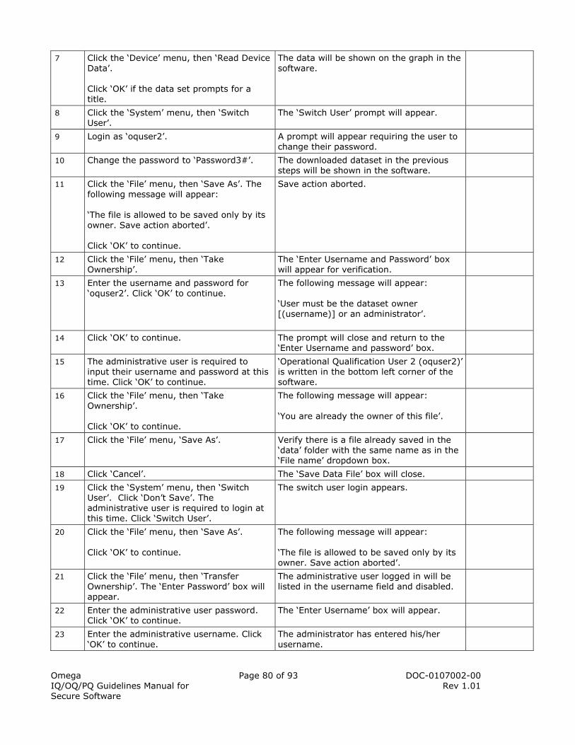
Omega IQ/OQ/PQ Guidelines Manual for Secure Software
Page 80 of 93 DOC-0107002-00 Rev 1.01
7 Click the ‘Device’ menu, then ‘Read Device Data’. Click ‘OK’ if the data set prompts for a title.
The data will be shown on the graph in the software.
8 Click the ‘System’ menu, then ‘Switch User’.
The ‘Switch User’ prompt will appear.
9 Login as ‘oquser2’. A prompt will appear requiring the user to change their password.
10 Change the password to ‘Password3#’. The downloaded dataset in the previous steps will be shown in the software.
11 Click the ‘File’ menu, then ‘Save As’. The following message will appear: ‘The file is allowed to be saved only by its owner. Save action aborted’. Click ‘OK’ to continue.
Save action aborted.
12 Click the ‘File’ menu, then ‘Take Ownership’.
The ‘Enter Username and Password’ box will appear for verification.
13 Enter the username and password for ‘oquser2’. Click ‘OK’ to continue.
The following message will appear: ‘User must be the dataset owner [(username)] or an administrator’.
14 Click ‘OK’ to continue. The prompt will close and return to the ‘Enter Username and password’ box.
15 The administrative user is required to input their username and password at this time. Click ‘OK’ to continue.
‘Operational Qualification User 2 (oquser2)’ is written in the bottom left corner of the software.
16 Click the ‘File’ menu, then ‘Take Ownership’. Click ‘OK’ to continue.
The following message will appear: ‘You are already the owner of this file’.
17 Click the ‘File’ menu, ‘Save As’. Verify there is a file already saved in the ‘data’ folder with the same name as in the ‘File name’ dropdown box.
18 Click ‘Cancel’. The ‘Save Data File’ box will close.
19 Click the ‘System’ menu, then ‘Switch User’. Click ‘Don’t Save’. The administrative user is required to login at this time. Click ‘Switch User’.
The switch user login appears.
20 Click the ‘File’ menu, then ‘Save As’. Click ‘OK’ to continue.
The following message will appear: ‘The file is allowed to be saved only by its owner. Save action aborted’.
21 Click the ‘File’ menu, then ‘Transfer Ownership’. The ‘Enter Password’ box will appear.
The administrative user logged in will be listed in the username field and disabled.
22 Enter the administrative user password. Click ‘OK’ to continue.
The ‘Enter Username’ box will appear.
23 Enter the administrative username. Click ‘OK’ to continue.
The administrator has entered his/her username.

Omega IQ/OQ/PQ Guidelines Manual for Secure Software
Page 81 of 93 DOC-0107002-00 Rev 1.01
24 Click the ‘File’ menu, then ‘Take Ownership’.
A prompt will appear stating: ‘You are already the owner of this file.’
25 Click ‘OK’. Close the open dataset without saving.
The open dataset is closed.
Summary This completes the Take Ownership/Transfer Ownership section of the OQ procedure.
Notes
Implemented by:_________________________________ Date:_____________________ Signature: ______________________________________________ Reviewed by:____________________________________ Date:_____________________ Signature: ______________________________________________
2.10.14 CHANGE PASSWORD
The password can be changed manually by any administrator or user when they are logged in the software. This is allowed at anytime in addition to the system enforced password policies set by the administrator. The individual performing the installation should initial the appropriate box upon completion of each step and sign and date the end of the procedure after completion.
Change Password
Step Task Acceptance Criteria Initial
1 Click the ‘System’ menu, then ‘Switch User’. Login as ‘oquser2’.
‘oquser2’ will be logged in.
2 Click the ‘System’ menu, then ‘Change Password’.
The ‘Change Password’ prompt box will appear.
3 Enter the old password of the user logged in. Enter ‘Password2!’ as the new password and confirm it. Click ‘OK’ to continue.
A prompt will appear stating the password changed successfully.
4 Click ‘OK’ to continue. The password has been successfully changed.
Summary This completes the Change Password section of the OQ procedure.
Notes
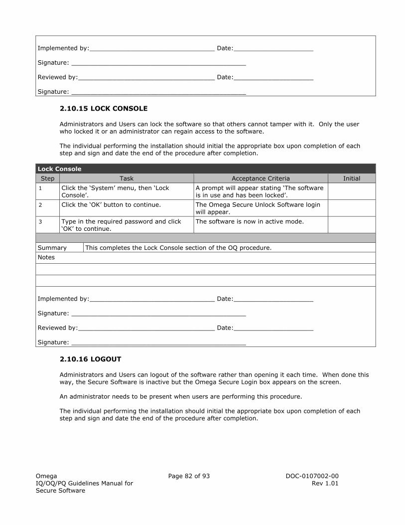
Omega IQ/OQ/PQ Guidelines Manual for Secure Software
Page 82 of 93 DOC-0107002-00 Rev 1.01
Implemented by:_________________________________ Date:_____________________ Signature: ______________________________________________ Reviewed by:____________________________________ Date:_____________________ Signature: ______________________________________________
2.10.15 LOCK CONSOLE
Administrators and Users can lock the software so that others cannot tamper with it. Only the user who locked it or an administrator can regain access to the software. The individual performing the installation should initial the appropriate box upon completion of each step and sign and date the end of the procedure after completion.
Lock Console
Step Task Acceptance Criteria Initial
1 Click the ‘System’ menu, then ‘Lock Console’.
A prompt will appear stating ‘The software is in use and has been locked’.
2 Click the ‘OK’ button to continue. The Omega Secure Unlock Software login will appear.
3 Type in the required password and click ‘OK’ to continue.
The software is now in active mode.
Summary This completes the Lock Console section of the OQ procedure.
Notes
Implemented by:_________________________________ Date:_____________________ Signature: ______________________________________________ Reviewed by:____________________________________ Date:_____________________ Signature: ______________________________________________
2.10.16 LOGOUT
Administrators and Users can logout of the software rather than opening it each time. When done this way, the Secure Software is inactive but the Omega Secure Login box appears on the screen. An administrator needs to be present when users are performing this procedure. The individual performing the installation should initial the appropriate box upon completion of each step and sign and date the end of the procedure after completion.

Omega IQ/OQ/PQ Guidelines Manual for Secure Software
Page 83 of 93 DOC-0107002-00 Rev 1.01
Logout
Step Task Acceptance Criteria Initial
1 Click the ‘System’ menu, then ‘Logout’. A Omega Secure prompt will appear stating: ‘Are you sure you want to log out?’
2 Click ‘Yes’ to continue. The Omega Secure Login box will appear.
3 Login as the administrative user. The administrative user will now be logged in.
4 Click the ‘System’ menu, then ‘User Management’.
The ‘User Management’ box will appear.
5 Click ‘oquser2’. Check the box beside ‘Account Disabled’. Click ‘Save’, then ‘Yes’.
The ‘oquser2’ account is disabled at this time because it will not be used in the remainder of this IQ/OQ/PQ procedure. It is only to be enabled to train users using the ‘Employee Training Guide’.
6 Click ‘OK’ to close the User Management box.
The box will close.
Summary This completes the Logout section of the OQ procedure.
Notes
Implemented by:_________________________________ Date:_____________________ Signature: ______________________________________________ Reviewed by:____________________________________ Date:_____________________ Signature: ______________________________________________
2.11 UNCONTROLLED CIRCUMSTANCES
There are certain unexpected circumstances that can occur to the end user while using the Omega Secure Software. These circumstances include disconnection of data logger while programming or power failure while trying to communicate with the data logger. If either circumstance occurs while trying to start or stop a recorder, it will not be fully or properly programmed until the software displays the ‘Device started’ or ‘Device stopped’ prompt. In the instance that data was being downloaded, the following procedure ensures that incomplete data cannot be obtained from a data logger.
2.11.1 DISCONNECTING THE DATA LOGGER WHILE DOWNLOADING
Disconnecting the Data Logger while Downloading
Step Task Acceptance Criteria Initial
1 If the administrator is logged in at this time, switch users to the username being trained.
The trainee will be logged in.

Omega IQ/OQ/PQ Guidelines Manual for Secure Software
Page 84 of 93 DOC-0107002-00 Rev 1.01
2 Start the data logger. Refer to procedure 2.12.2 (2.13.2 for 2000 Series), Starting a Data Logger. Set it to ‘Start Now’ and log at the fastest possible reading rate. Click the ‘Start’ button. Click ‘OK’ to continue.
The data logger will be running.
3 Let the data logger run for five minutes. The data logger will run for five minutes.
4 Click the ‘Device’ menu, then ‘Stop Device’. Click ‘Yes’. Click ‘OK’
The data logger will stop.
5 Hold the interface cable and data logger. The data logger will need to be disconnected from the interface cable. The download occurs quickly, be prepared. Click the ‘Device’ menu, then ‘Read Device Data’ Disconnect the data logger when the following message appears: ‘Processing, please wait’.
A prompt will appear stating: ‘Unable to find an active device!’
6 Click ‘OK’ to continue. The prompt will close.
7 Connect the data logger to the interface cable and click the ‘Device’ menu, then ‘Read Device Data’. In the bottom right corner, when the message ‘Reading Device Data’ appears, completely disconnect the data logger from the interface cable.
After a short interval a message will appear stating: ‘Failed to download packet number [number]. Do you want to continue the download?’
8 Click the ‘Retry’ button to continue. After a short interval a message will appear stating: ‘Failed to download packet number [number]. Do you want to continue the download?’
9 Click ‘Cancel’. A prompt will appear stating: ‘Unable to download the device data. Communications error (33024)’.
10 Click ‘OK’ to continue. No data will be shown in the software.
11 Click ‘File’, then ‘Open’. Verify that the only data files available, are those that were downloaded in previous procedures. Note. The data file names have the date and time they were downloaded.
The only available datasets saved will be the ones downloaded in the previous procedures.
12 Click the ‘Device’ menu, then ‘Read Device Data’.
Data will appear in the software. This verifies the data logger still retains the data, after disconnection while downloading.
13 Click the ‘File’ menu, then ‘Exit’. The Omega Secure software will close.

Omega IQ/OQ/PQ Guidelines Manual for Secure Software
Page 85 of 93 DOC-0107002-00 Rev 1.01
Summary This completes the Disconnecting the Data logger while Downloading section of the OQ procedure.
Notes
__________________________________________________________
__________________________________________________________
__________________________________________________________
__________________________________________________________
Implemented by:_________________________________ Date:_____________________ Signature: ______________________________________________ Reviewed by:____________________________________ Date:_____________________ Signature: ______________________________________________
2.12 SYSTEM ACCEPTANCE
This system is properly operating and has passed all functional procedures.
Installed By:
(Print Name)
Signature: Date:
Functional Procedures Performed By:
(Print Name)
Signature: Date:
Approved By:
(Print Name)
Signature: Date:
Omega IQ/OQ/PQ Guidelines Manual for Secure Software
Page 86 of 93 DOC-0107002-00 Rev 1.01
3 PERFORMANCE QUALIFICATION (PQ)
Omega supplies this Performance Qualification (PQ) document as a reference for and aid to the user for validation requirements associated with the use and performance of the Omega Secure System in a regulated environment. This document is designed to help develop the customer’s validation plan as defined in the FDA current Good Manufacturing Practice (see 21 CFR 820).
3.1 PURPOSE
The purpose of this document is to establish that the Omega Secure system performs as specified in the selected environment.
3.2 RESPONSIBILITIES
For a complete Omega Secure System, there are responsibilities of Omega, Inc. as well as the end user for compliance with 21 CFR Part 11. These responsibilities apply to the PQ procedure and are required to be maintained through out using the Omega Secure System. Standard operating procedures should be created and implemented for responsibilities.
3.2.1 OMEGA
• PQ Protocol template and acceptance guidelines • Example worksheet forms
3.2.2 END USER
• PQ Protocol preparation and approval • Proper handling and safety precautions for loggers and batteries • Maintaining workstations and system backups • Maintaining system hardware and calibration • Establishing controls to ensure continued performance • Record keeping practices for hardcopy and electronic data
3.3 SCOPE
The PQ Procedure for the Omega Secure System provides:
• Additional handling precautions for maintaining the accuracy of Omega equipment • Periodic maintenance information for the use of Omega equipment • Periodic calibration verification in the field • Comparison of the reported values to a known good standard
3.4 PERIODIC CALIBRATION AND MAINTENANCE
This section describes the proper handling and maintenance of the Omega data loggers. The following safety considerations and precautions should be observed during the use of all Omega data loggers.
3.4.1 DATA LOGGER HANDLING
Always observe the handling precautions outlined in the operational qualification procedure. Since calibration and maintenance can expose delicate sensors and electronics, also observe the following points:
• When handling the data loggers during calibration and maintenance, it is important to avoid unnecessary contact with the electronics. Electronics are sensitive to electrostatic discharge
Omega IQ/OQ/PQ Guidelines Manual for Secure Software
Page 87 of 93 DOC-0107002-00 Rev 1.01
(ESD), and proper ESD protection (such as grounded wrist straps) should be worn when disassembling the loggers.
• Sensors can be damaged by ESD, mechanical shock, and by a wide array of contaminants including human body oils. Direct contact with sensors should be avoided at all costs. If contact is unavoidable, the sensor calibration should be verified before continuing to use the logger.
3.4.2 SCHEDULED MAINTENANCE
Under most conditions, Omega data loggers will operate for a full year or longer on a new battery. The user should establish a periodic maintenance schedule appropriate to their application and pattern of use, typically based on the expected battery life.
• Periodic battery replacements should be scheduled yearly in most applications. • Battery replacement intervals are the most convenient time to inspect the logger enclosures
and electronics for damage or signs of wear. • Depending on the application, the user may choose to perform more regular inspections of the
equipment, most commonly during the periodic calibration checks.
3.4.3 PERIODIC CALIBRATION
Under most conditions, Omega data loggers will retain accurate measurement capability for a full year or longer after calibration. Particularly harsh environments may cause more rapid drift of sensor accuracy, and direct exposure of sensors or electronics to corrosive or reactive environments (e.g. humidity sensors exposed to ethylene oxide gas) may result in slow and irreversible damage to the sensor. Mishandling may also result in degraded performance. Since it may not be possible to visually detect a change in performance, the data loggers must be verified at periodic intervals to confirm that they are performing within permissible limits. Calibration recommendations are below:
• Observe the proper handling and maintenance procedures as outlined in the operational and performance qualification procedures.
• Periodically check the Omega data loggers against a known good standard such as the National Institute of Standards and Technology (NIST) to verify the device calibration. The total system uncertainty should not be more than 25% of the accuracy desired for the calibration, per ANSI Z540-1-1994 10.2b.
• Most applications should perform in-house calibration verification several times during the specified calibration interval. For a logger with a one-year calibration interval, quarterly calibration checks are usually appropriate.
• Return the loggers at longer intervals (such as the specified calibration interval) to Omega or a suitable calibration laboratory for independent calibration data.
3.4.4 BATTERIES
Most Omega data loggers have field replaceable batteries. Most of these batteries are Lithium Thionyl Chloride batteries. This means that special precautions and warnings must be heeded. The following warning should be read and appears on most Omega products and documentation:
3.4.4.1 BATTERY WARNING
Most Omega data loggers contain a lithium battery. Do not cut the battery open, incinerate, or recharge. Do not heat lithium batteries above 85 ºC unless the battery is specifically rated for higher temperatures. Dispose the battery in accordance with local regulations.
3.5 REFERENCE CALIBRATION PROCEDURES
It is recommended that periodically each data logger should be verified against a traceable standard. The following guidelines can be used to verify the data logger’s accuracy.

Omega IQ/OQ/PQ Guidelines Manual for Secure Software
Page 88 of 93 DOC-0107002-00 Rev 1.01
3.5.1 OMEGA TEMPERATURE DATA LOGGERS
The below steps are guidelines providing a method for verifying the temperature measurement accuracy of Omega data loggers. These guidelines can be performed on a temperature data logger any time accuracy needs to be verified. Omega recommends implementing these guidelines into a Standard Operating Procedure(s) at the end users facility.
3.5.1.1 TEMPERATURE VERIFICATION OUTLINE
Temperature Calibration Procedure
Step
1 Select a calibration interval. Most Omega temperature data loggers use a precision semiconductor band gap temperature sensor. In some cases, a precision PT100 RTD temperature sensor is used. These sensors were chosen based on their reliability and long-term stability. Omega recommends that these temperature sensors be recalibrated every year.
2 Select the desired calibration points. Omega temperature data loggers are normally tested at several temperature points. It is recommended that temperature points be used that are relevant to the target process. For example, using data loggers in an autoclave sterilization application would suggest using 121 ºC as a verification point.
3 Prepare the reference equipment. The calibration data is collected by immersing the data logger into an environment that provides a uniform, stable temperature over a minimum period of time of 30 minutes. In addition, there should be a reference temperature meter to compare the reference temperature to that read by the data logger. The environment into which the data logger is immersed can be a temperature controlled liquid circulated bath or a temperature controlled air-circulated oven. In either case, it is critical that the environment around the data logger be uniform and stable and accurately monitored by a reference temperature meter. See the next step on starting the data loggers prior to immersing them into the reference environment.
4 Deploy the data loggers. Start the data loggers to record a reading every 1 minute starting 15 minutes prior to immersing them into the bath or placing them into the oven. The computer clock should be synchronized with the time standard being used, as the data loggers will get their time from the computer clock.
5 Collect the calibration data by immersing the logger in each of the selected environments for a minimum of 30 minutes and verifying the temperature stability using the reference standard. Record several temperature readings from the reference standard near the end of the immersion in each calibration environment. Note. Write the time of each reading for later comparison with the logger data. Be sure to cycle the logger through all the relevant calibration environments before continuing.
6 Download the temperature readings from the data loggers and compare them with those read by the reference meter.
3.5.1.2 TEMPERATURE CALIBRATION NOTES
Notes regarding the selection of reference standards:
▪ Reference temperature standards should be accurate to 0.05 ºC or better and traceable to NIST
Notes regarding the use of ovens or environmental chambers:
▪ Ovens and environmental chambers should be installed, operated and maintained in accordance with the manufacturer’s instructions
Notes regarding the use of constant temperature liquid circulating baths:

Omega IQ/OQ/PQ Guidelines Manual for Secure Software
Page 89 of 93 DOC-0107002-00 Rev 1.01
▪ Constant temperature liquid circulating baths are recommended to provide the temperature environment up to 150 ºC with minimum specifications of 0.005 ºC uniformity and 0.005 ºC stability
▪ Constant temperature baths should be installed, operated and maintained in accordance with the bath manufacturer’s instructions
▪ When using temperature baths, observe the instructions on the Material Safety Data Sheets (MSDS) provided by the manufacturer of the fluid
▪ Dow silicone 200 fluid with a viscosity of 5 centistokes is recommended as the medium in the constant temperature bath for temperatures below 10 º C
▪ Distilled water can be used between 10 ºC and 80 ºC ▪ Dow silicone 200 fluid with a viscosity of 20 centistokes is recommended as the medium in
constant temperature baths for temperatures between 80 ºC and 150 ºC. Silicone fluid should not be heated above 150 ºC for Omega data loggers
▪ If the data logger being calibrated is not water resistant, it must be vacuum-sealed inside a waterproof plastic container or bag. The container must be designed to withstand the temperatures encountered in the calibration environment
▪ The data loggers should be placed into the bath in such a way that the sensing element or probe tip is positioned at least 1” away from the bottom or sides of the bath and at least 1½” below the surface of the fluid
▪ Cover the bath with the lid and insert the probe of the reference standard into the hole in the lid. Slide it into a level that positions the probe tip into the middle of the bath. It is best to position the reference probe and the data logger sensing elements as close as possible to each other without them touching. Observe the minimum immersion depth of the reference probe
3.5.2 OMEGA HUMIDITY DATA LOGGERS
The below steps are guidelines providing a method for verifying the humidity measurement accuracy of Omega data loggers. These guidelines can be performed on a humidity data logger any time accuracy needs to be verified. Temperature calibration accuracy should be verified as described in the previous section before verifying the humidity calibration accuracy. If a temperature bath is used for the temperature calibration verification, then the humidity sensor must be protected. In the case of the OM-CP-RHTemp1000 and OM-CP-RHTemp1000IS, there is a cap that closes to make the device waterproof. The OM-CP-RHTemp101, OM-CP-RHTemp110, OM-CP-MicroRHTemp and other Omega humidity loggers are not waterproof and therefore need to be encapsulated in a waterproof enclosure before they can be used in a temperature controlled liquid bath. Omega recommends the end user implement SOP’s incorporating the guidelines given below.
3.5.2.1 HUMIDITY VERIFICATION OUTLINE
Humidity Calibration Procedure
Step
1 Select a calibration interval. Most Omega humidity data loggers use a highly accurate capacitive humidity sensor. These sensors were chosen based on their reliability and long-term stability. Omega recommends that these humidity sensors be recalibrated at least once a year.
2 Select the desired calibration points. Omega humidity data loggers are normally tested at several humidity points. It is recommended that humidity points be used that are relevant to the target process. For wide range humidity calibration, the best performance is generally achieved by selecting a low correction point in the range of 20-30 %RH and a high correction point in the range of 70-80 %RH.
3 Prepare the reference equipment. The calibration data is collected by immersing the data logger into an environment that provides a uniform, stable humidity over a minimum time period of 15 minutes. In addition, there should be a reference hygrometer to verify environment stability or to measure reference values. The environment into which the data logger is immersed can be a humidity generator, environmental chamber, or container of saturated salt solution.
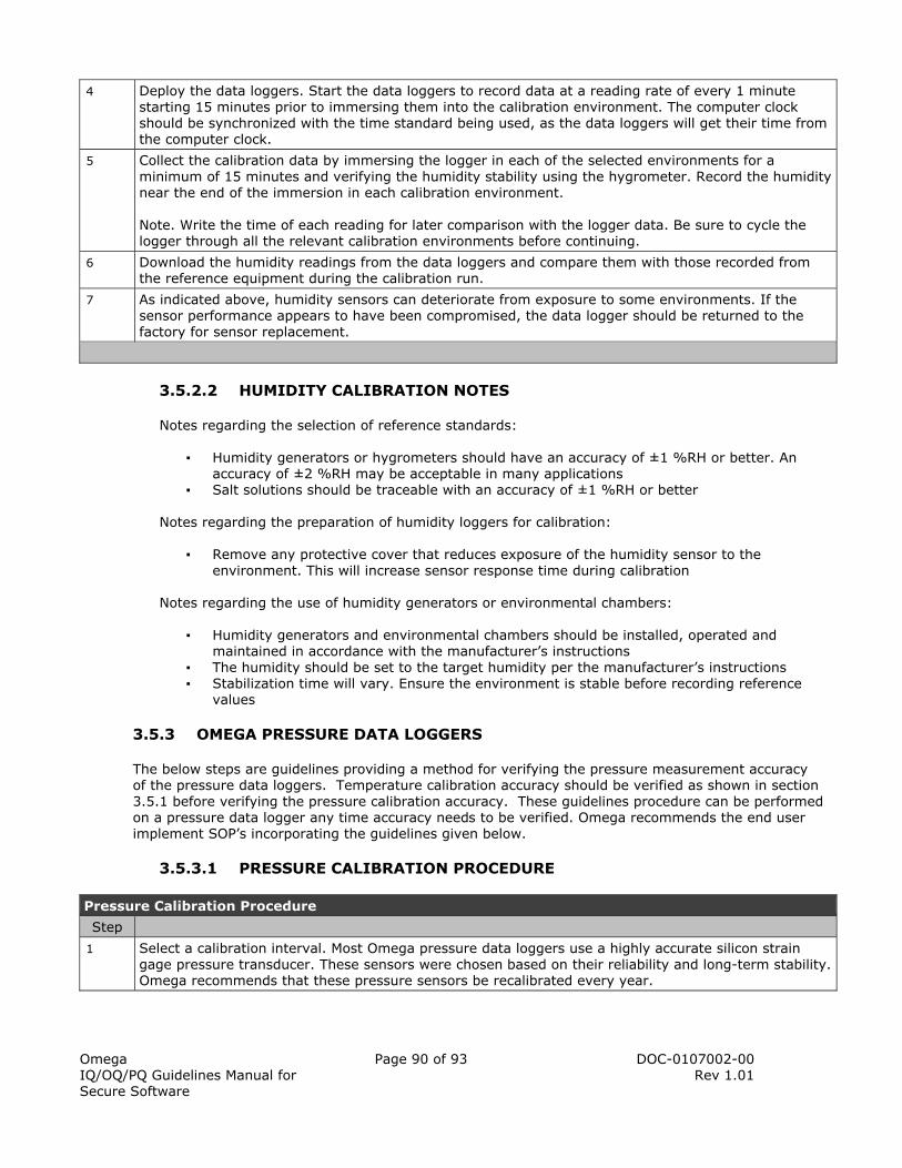
Omega IQ/OQ/PQ Guidelines Manual for Secure Software
Page 90 of 93 DOC-0107002-00 Rev 1.01
4 Deploy the data loggers. Start the data loggers to record data at a reading rate of every 1 minute starting 15 minutes prior to immersing them into the calibration environment. The computer clock should be synchronized with the time standard being used, as the data loggers will get their time from the computer clock.
5 Collect the calibration data by immersing the logger in each of the selected environments for a minimum of 15 minutes and verifying the humidity stability using the hygrometer. Record the humidity near the end of the immersion in each calibration environment. Note. Write the time of each reading for later comparison with the logger data. Be sure to cycle the logger through all the relevant calibration environments before continuing.
6 Download the humidity readings from the data loggers and compare them with those recorded from the reference equipment during the calibration run.
7 As indicated above, humidity sensors can deteriorate from exposure to some environments. If the sensor performance appears to have been compromised, the data logger should be returned to the factory for sensor replacement.
3.5.2.2 HUMIDITY CALIBRATION NOTES
Notes regarding the selection of reference standards:
▪ Humidity generators or hygrometers should have an accuracy of ±1 %RH or better. An accuracy of ±2 %RH may be acceptable in many applications
▪ Salt solutions should be traceable with an accuracy of ±1 %RH or better Notes regarding the preparation of humidity loggers for calibration:
▪ Remove any protective cover that reduces exposure of the humidity sensor to the environment. This will increase sensor response time during calibration
Notes regarding the use of humidity generators or environmental chambers:
▪ Humidity generators and environmental chambers should be installed, operated and maintained in accordance with the manufacturer’s instructions
▪ The humidity should be set to the target humidity per the manufacturer’s instructions ▪ Stabilization time will vary. Ensure the environment is stable before recording reference
values
3.5.3 OMEGA PRESSURE DATA LOGGERS
The below steps are guidelines providing a method for verifying the pressure measurement accuracy of the pressure data loggers. Temperature calibration accuracy should be verified as shown in section 3.5.1 before verifying the pressure calibration accuracy. These guidelines procedure can be performed on a pressure data logger any time accuracy needs to be verified. Omega recommends the end user implement SOP’s incorporating the guidelines given below.
3.5.3.1 PRESSURE CALIBRATION PROCEDURE
Pressure Calibration Procedure
Step
1 Select a calibration interval. Most Omega pressure data loggers use a highly accurate silicon strain gage pressure transducer. These sensors were chosen based on their reliability and long-term stability. Omega recommends that these pressure sensors be recalibrated every year.

Omega IQ/OQ/PQ Guidelines Manual for Secure Software
Page 91 of 93 DOC-0107002-00 Rev 1.01
2 Select the desired calibration points. Omega pressure data loggers are normally tested at several pressure points. It is recommended that pressure points be used that are relevant to the target process. For wide range pressure calibration, the best performance is generally achieved by selecting a low correction point near the low extreme of the measurable range of the sensor and a high correction point at the high extreme of the measurable range of the sensor (e.g. 90% of full scale range).
3 Prepare the reference equipment. The calibration data is collected by exposing the data logger to a pressure reference that provides a uniform, stable pressure over a short period of time. In addition, there should be a reference barometer to verify pressure stability and measure reference values. Most pressure standards combine a pressure source and a reference barometer.
4 Deploy the data loggers. Start the data loggers to record a reading every 5 seconds starting a few minutes prior to exposing them to the calibration source. The computer clock should be synchronized with the time standard being used, as the data loggers will get their time from the computer clock.
5 Collect the calibration data by exposing the logger to the pressure standards and verifying the stability using the barometer. Expose the logger to the pressure source for 30 seconds or longer for each value. Record the exact pressure during the exposure to each pressure value. Note. Write the time of each reading for later comparison with the logger data. Be sure to cycle the logger through all the relevant pressure values before continuing.
6 Download the pressure readings from the data loggers and compare them with those recorded from the reference standard during the calibration run.
3.5.3.2 PRESSURE CALIBRATION NOTES
Notes regarding the selection of reference standards:
▪ The reference pressure used should be accurate to 4 times the target accuracy of the data logger or better and be NIST traceable
▪ The pressure standard should be stable to within the rated accuracy over a one minute interval
3.6 CALIBRATION RECORDS
The results of the calibration verification should be recorded in a table similar to the following and kept on file.
Calibration Verification Summary
Model Serial Number Last Calibration Date Verification Date
Reference Value Reported Value Error
Operator Name

Omega IQ/OQ/PQ Guidelines Manual for Secure Software
Page 92 of 93 DOC-0107002-00 Rev 1.01
3.7 STANDARD OPERATING PROCEDURES
It is recommended that the reference procedures and summary format above be evaluated by the end user and incorporated into the system owner’s standard operating procedures (SOPs). Compliance with 21 CFR Part 11 relies on software providing technical abilities for compliance, along with the end user implementing standard operating procedures to maintain them. Responsibilities of the end user for the IQ/OQ/PQ guidelines should have SOP’s generated to ensure they are regularly maintained. The Omega Secure Worksheet Forms are provided as examples for assistance with SOP’s. Omega recommends generating and implementing the following SOP’s for Hardware and Software.
3.7.1 HARDWARE
• Proper Handling and Safety Precautions • Recommended intervals for calibration, battery and sensor replacement • General maintenance/inspection criteria (re-calibration cycle, system backup, etc.)
3.7.2 SOFTWARE
• Limiting System Access • Software is on a closed system
• Defining user roles in the system • Who is an administrator; who is a user • Define the meanings of electronic signatures
• Training users • Password assignment and secrecy • Creating and updating accounts • User identity and personal accountability
• Written policy holding users accountable for their actions • Security overview; security settings and preferences • Periodic review of the audit trail; security settings and user accounts • Record keeping practices for hardcopy and electronic data • Software maintenance and updates • Maintaining workstation and system backups

Omega IQ/OQ/PQ Guidelines Manual for Secure Software
Page 93 of 93 DOC-0107002-00 Rev 1.01
3.8 SYSTEM ACCEPTANCE
This system has passed all performance qualifications.
Installed By:
(Print Name)
Signature: Date:
Functional Procedures Performed By:
(Print Name)
Signature: Date:
Approved By:
(Print Name)
Signature: Date:

WARRANTY/DISCLAIMEROMEGA ENGINEERING, INC. warrants this unit to be free of defects in materials and workmanship for aperiod of 13 months from date of purchase. OMEGA’s WARRANTY adds an additional one (1) monthgrace period to the normal one (1) year product warranty to cover handling and shipping time. Thisensures that OMEGA’s customers receive maximum coverage on each product. If the unit malfunctions, it must be returned to the factory for evaluation. OMEGA’s Customer ServiceDepartment will issue an Authorized Return (AR) number immediately upon phone or written request.Upon examination by OMEGA, if the unit is found to be defective, it will be repaired or replaced at nocharge. OMEGA’s WARRANTY does not apply to defects resulting from any action of the purchaser,including but not limited to mishandling, improper interfacing, operation outside of design limits, improper repair, or unauthorized modification. This WARRANTY is VOID if the unit shows evidence of having been tampered with or shows evidence of having been damaged as a result of excessive corrosion;or current, heat, moisture or vibration; improper specification; misapplication; misuse or other operatingconditions outside of OMEGA’s control. Components in which wear is not warranted, include but are not limited to contact points, fuses, and triacs.OMEGA is pleased to offer suggestions on the use of its various products. However, OMEGA neither assumes responsibility for any omissions or errors nor assumes liability for anydamages that result from the use of its products in accordance with information provided byOMEGA, either verbal or written. OMEGA warrants only that the parts manufactured by thecompany will be as specified and free of defects. OMEGA MAKES NO OTHER WARRANTIES OR REPRESENTATIONS OF ANY KIND WHATSOEVER, EXPRESSED OR IMPLIED, EXCEPT THAT OFTITLE, AND ALL IMPLIED WARRANTIES INCLUDING ANY WARRANTY OF MERCHANTABILITYAND FITNESS FOR A PARTICULAR PURPOSE ARE HEREBY DISCLAIMED. LIMITATION OF LIABILITY: The remedies of purchaser set forth herein are exclusive, and the total liability of OMEGA with respect to this order, whether based on contract, warranty, negligence, indemnification, strict liability or otherwise, shall not exceed the purchase price of the component upon which liability is based. In no event shall OMEGA be liable for consequential, incidental or special damages.CONDITIONS: Equipment sold by OMEGA is not intended to be used, nor shall it be used: (1) as a “BasicComponent” under 10 CFR 21 (NRC), used in or with any nuclear installation or activity; or (2) in medicalapplications or used on humans. Should any Product(s) be used in or with any nuclear installation oractivity, medical application, used on humans, or misused in any way, OMEGA assumes no responsibilityas set forth in our basic WARRANTY/DISCLAIMER language, and, additionally, purchaser will indemnifyOMEGA and hold OMEGA harmless from any liability or damage whatsoever arising out of the use of theProduct(s) in such a manner.
RETURN REQUESTS/INQUIRIESDirect all warranty and repair requests/inquiries to the OMEGA Customer Service Department. BEFORERETURNING ANY PRODUCT(S) TO OMEGA, PURCHASER MUST OBTAIN AN AUTHORIZED RETURN(AR) NUMBER FROM OMEGA’S CUSTOMER SERVICE DEPARTMENT (IN ORDER TO AVOIDPROCESSING DELAYS). The assigned AR number should then be marked on the outside of the returnpackage and on any correspondence.The purchaser is responsible for shipping charges, freight, insurance and proper packaging to preventbreakage in transit.
FOR WARRANTY RETURNS, please have the following information available BEFORE contacting OMEGA:1. Purchase Order number under which the product
was PURCHASED,2. Model and serial number of the product under
warranty, and3. Repair instructions and/or specific problems
relative to the product.
FOR NON-WARRANTY REPAIRS, consult OMEGAfor current repair charges. Have the followinginformation available BEFORE contacting OMEGA:1. Purchase Order number to cover the COST
of the repair,2. Model and serial number of the product, and3. Repair instructions and/or specific problems
relative to the product.
OMEGA’s policy is to make running changes, not model changes, whenever an improvement is possible. This affordsour customers the latest in technology and engineering.OMEGA is a registered trademark of OMEGA ENGINEERING, INC.© Copyright 2010 OMEGA ENGINEERING, INC. All rights reserved. This document may not be copied, photocopied,reproduced, translated, or reduced to any electronic medium or machine-readable form, in whole or in part, without theprior written consent of OMEGA ENGINEERING, INC.

M4921/0510
Where Do I Find Everything I Need for Process Measurement and Control?
OMEGA…Of Course!Shop online at omega.com SM
TEMPERATURE�� Thermocouple, RTD & Thermistor Probes, Connectors, Panels & Assemblies�� Wire: Thermocouple, RTD & Thermistor�� Calibrators & Ice Point References�� Recorders, Controllers & Process Monitors�� Infrared Pyrometers
PRESSURE, STRAIN AND FORCE�� Transducers & Strain Gages�� Load Cells & Pressure Gages�� Displacement Transducers�� Instrumentation & Accessories
FLOW/LEVEL�� Rotameters, Gas Mass Flowmeters & Flow Computers�� Air Velocity Indicators�� Turbine/Paddlewheel Systems�� Totalizers & Batch Controllers
pH/CONDUCTIVITY�� pH Electrodes, Testers & Accessories�� Benchtop/Laboratory Meters�� Controllers, Calibrators, Simulators & Pumps�� Industrial pH & Conductivity Equipment
DATA ACQUISITION�� Data Acquisition & Engineering Software�� Communications-Based Acquisition Systems�� Plug-in Cards for Apple, IBM & Compatibles�� Data Logging Systems�� Recorders, Printers & Plotters
HEATERS�� Heating Cable�� Cartridge & Strip Heaters�� Immersion & Band Heaters�� Flexible Heaters�� Laboratory Heaters
ENVIRONMENTALMONITORING AND CONTROL�� Metering & Control Instrumentation�� Refractometers�� Pumps & Tubing�� Air, Soil & Water Monitors�� Industrial Water & Wastewater Treatment�� pH, Conductivity & Dissolved Oxygen Instruments