Software Engineering Mostafa M. Aref 2011 l Text Book: l Software Engineering, 8th Edition, Ian...
113
Software Engineering Software Engineering Mostafa M. Aref 2011 Text Book: Software Engineering, 8th Edition, Ian Sommerville, University of St. Andrews, United Kingdom , ISBN-10: 0321313798, Addison-Wesley, 2006.
-
Upload
horatio-ryan -
Category
Documents
-
view
217 -
download
0
Transcript of Software Engineering Mostafa M. Aref 2011 l Text Book: l Software Engineering, 8th Edition, Ian...

Software EngineeringSoftware Engineering
Mostafa M. Aref
2011
Text Book: Software Engineering, 8th Edition, Ian Sommerville, University of St. Andrews, United Kingdom , ISBN-
10: 0321313798, Addison-Wesley, 2006.
Table of Contents Chapter 11: Chapter 11: Architectural DesignArchitectural Design Chapter 13: Chapter 13: Application ArchitecturesApplication Architectures Chapter 14: Chapter 14: Object-oriented DesignObject-oriented Design Chapter 16: Chapter 16: User Interface DesignUser Interface Design Chapter 17: Chapter 17: Rapid Software DevelopmentRapid Software Development Chapter 18: Chapter 18: Software ReuseSoftware Reuse Chapter 23: Chapter 23: Software TestingSoftware Testing

Chapter 11: Chapter 11: Architectural DesignArchitectural Design Objectives
– To introduce architectural design and to discuss its importance– To explain the architectural design decisions that have to be
made– To introduce three complementary architectural styles
covering organisation, decomposition and control– To discuss reference architectures are used to communicate
and compare architectures Topics covered
– Architectural Design Decisions– System Organisation– Decomposition Styles– Control Styles– Reference Architectures
3

Software architecture Architectural Design
– Stakeholder Communication– System Analysis– Large-scale Reuse
System Characteristics– Performance, Security, Safety, Availability, Maintainability
Architectural conflicts System structuring Box and line diagrams Architectural design decisions
Visionsystem
Objectidentification
system
Armcontroller
Grippercontroller
Packagingselectionsystem
Packingsystem
Conveyorcontroller

Architectural design decisions– Is there a generic application architecture that can be used?– How will the system be distributed?– What architectural styles are appropriate?– What approach will be used to structure the system?– How will the system be decomposed into modules?– What control strategy should be used?– How will the architectural design be evaluated?– How should the architecture be documented?
Architecture reuse Architectural styles Architectural models
– Static structural, Dynamic process, Interface, Relationships, Distribution
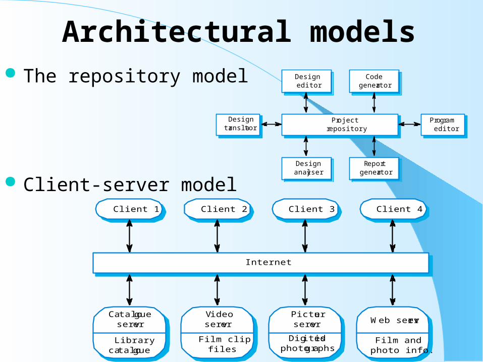
Architectural models The repository model
Client-server model
Projectrepository
Designtranslator
Programeditor
Designeditor
Codegenerator
Designanalyser
Reportgenerator
Catalogueserver
Librarycatalogue
Videoserver
Film clipfiles
Pictureserver
Digitisedphotographs
Web server
Film andphoto info.
Client 1 Client 2 Client 3 Client 4
Internet

Architectural models (2) Abstract machine (layered) model
Object models
Configuration management system layer
Database system layer
Operating system layer
Object management system layer
issue ()sendReminder ()acceptPayment ()sendReceipt ()
invoice#dateamountcustomer
invoice#dateamountcustomer#
invoice#dateamountcustomer#
customer#nameaddresscredit period
Customer
Payment
Invoice
Receipt
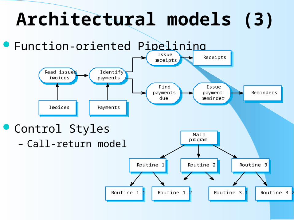
Architectural models (3) Function-oriented Pipelining
Control Styles– Call-return model
Read issuedinvoices
Identifypayments
Issuereceipts
Findpayments
due
Receipts
Issuepaymentreminder
Reminders
Invoices Payments
Routine 1.2Routine 1.1 Routine 3.2Routine 3.1
Routine 2 Routine 3Routine 1
Mainprogram

Architectural models (4) Control Styles
– Real-time system control
– Event-driven systems
– Broadcast model
Systemcontroller
Userinterface
Faulthandler
Computationprocesses
Actuatorprocesses
Sensorprocesses
Sub-system1
Event and message handler
Sub-system2
Sub-system3
Sub-system4

Architectural models (5)– Interrupt-driven control
– OSI reference model
– The ECMA reference model
Handler1
Handler2
Handler3
Handler4
Process1
Process2
Process3
Process4
Interrupts
Interruptvector
Presentation
Session
Transport
Network
Data link
Physical
7
6
5
4
3
2
1
Communications medium
Network
Data link
Physical
Application
Presentation
Session
Transport
Network
Data link
Physical
Application
Toolslots
Messageservices
Task management services
User interface services
Data repository services
Data integration services

Key points– The software architecture is the fundamental framework for
structuring the system.– Architectural design decisions include decisions on the
application architecture, the distribution and the architectural styles to be used.
– Different architectural models such as a structural model, a control model and a decomposition model may be developed.
– System organisational models include repository models, client-server models and abstract machine models.
– Modular decomposition models include object models and pipelining models.
– Control models include centralised control and event-driven models.
– Reference architectures may be used to communicate domain-specific architectures and to assess and compare architectural designs.
Chapter 13: Chapter 13: Application ArchitecturesApplication Architectures Objectives
– To explain the organisation of two fundamental models of business systems - batch processing and transaction processing systems
– To describe the abstract architecture of resource management systems
– To explain how generic editors are event processing systems– To describe the structure of language processing systems
Topics covered– Data processing systems– Transaction processing systems– Event processing systems– Language processing systems
12

Application Type ExamplesApplication Type Examples Data processing systems
– Billing systems;
– Payroll systems. Transaction processing systems
– E-commerce systems;
– Reservation systems. Event processing systems
– Word processors;
– Real-time systems. Language processing systems
– Compilers;
– Command interpreters.
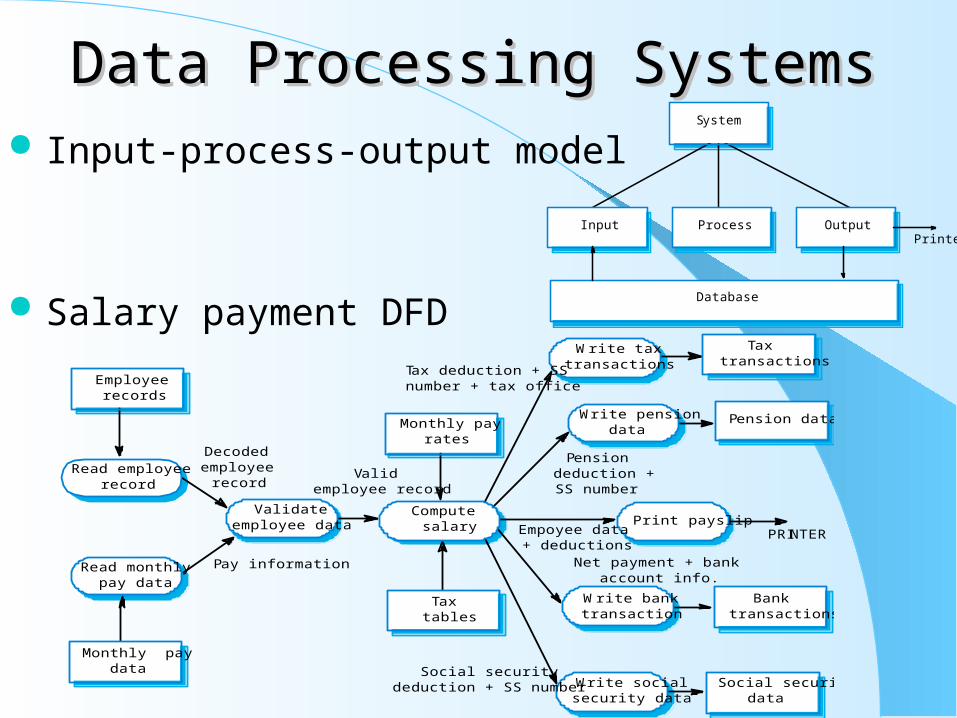
Data Processing SystemsData Processing Systems Input-process-output model
Salary payment DFD
System
Input Process OutputPrinter
Database
Read employeerecord
Read monthlypay data
Computesalary
Write taxtransactions
Monthly paydata
Taxtables
Taxtransactions
Pension data
Validateemployee data
Write pensiondata
Write banktransaction
Write socialsecurity data
Employeerecords
Monthly payrates
Banktransactions
Social securitydata
Print payslipPRINTER
Decodedemployee
record
Pay information
Validemployee record
Tax deduction + SSnumber + tax office
Pensiondeduction +SS number
Empoyee data+ deductions
Net payment + bankaccount info.
Social securitydeduction + SS number
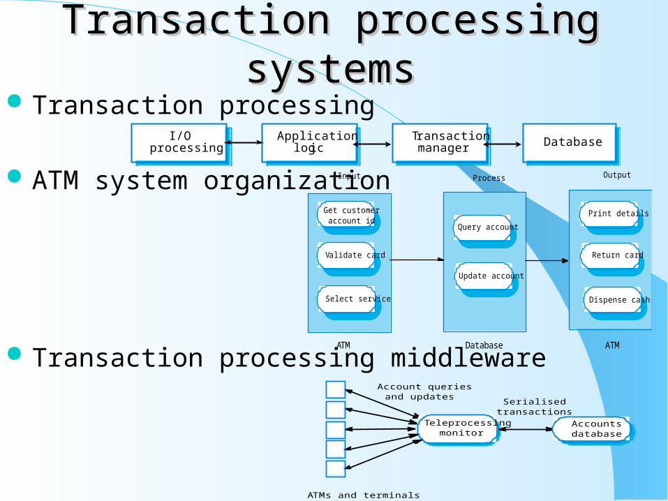
Transaction processing systemsTransaction processing systems Transaction processing
ATM system organization
Transaction processing middleware
I/Oprocessing
Applicationlogic
Transactionmanager Database
Get customeraccount id
Validate card
Input
Query account
Update account
Print details
Return card
Dispense cash
Process Output
Select service
ATM Database ATM
Serialisedtransactions
Teleprocessingmonitor
Accountsdatabase
ATMs and terminals
Account queriesand updates
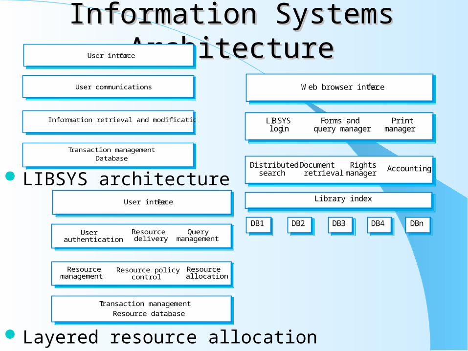
Information Systems ArchitectureInformation Systems Architecture
LIBSYS architecture
Layered resource allocation
User interface
Information retrieval and modification
DatabaseTransaction management
User communications Web browser interface
Distributedsearch Accounting
LIBSYSlogin
Forms andquery manager
Library index
Documentretrieval
DB1 DB2 DB3 DB4 DBn
Rightsmanager
Printmanager
User interface
Resourcemanagement
Resource policycontrol
Resourceallocation
Userauthentication
Querymanagement
Resource database
Resourcedelivery
Transaction management

E-commerce System ArchitectureE-commerce System Architecture
Event processing systems– Editing system architecture
Webbrowser Web server Application
serverDatabase
server
File System
SaveOpen
Editor data
Editingcommands
Ancillary data
Ancillarycommands
Command
Interpret
Screen
Refresh
Display
Update
Event
Process
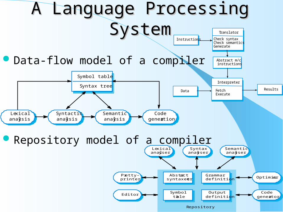
A Language Processing SystemA Language Processing System
Data-flow model of a compiler
Repository model of a compiler
Translator
Check syntaxCheck semanticsGenerate
Interpreter
FetchExecute
Abstract m/cinstructions
Data Results
Instructions
Lexicalanalysis
Syntacticanalysis
Semanticanalysis
Codegeneration
Symbol table
Syntax tree
Syntaxanalyser
Lexicalanalyser
Semanticanalyser
Abstractsyntax tree
Grammardefinition
Symboltable
Outputdefinition
Pretty-printer
Editor
Optimiser
Codegenerator
Repository
Key pointsKey points Generic models of application architectures help us understand
and compare applications. Important classes of application are data processing systems,
transaction processing systems, event processing systems and language processing system.
Data processing systems operate in batch mode and have an input-process-output structure.
Transaction processing systems allow information in a database to be remotely accessed and modified by multiple users.
Event processing systems include editors and real-time systems. In an editor, user interface events are detected and an in-store
data structure is modified. Language processing systems translate texts from one language to
another and may interpret the specified instructions.

Chapter 14: Chapter 14: Object-oriented DesignObject-oriented Design Objectives
– To explain how a software design may be represented as a set of interacting objects that manage their own state and operations
– To describe the activities in the object-oriented design process– To introduce various models that can be used to describe an object-oriented design– To show how the UML may be used to represent these models
Topics covered– Objects and object classes
– An object-oriented design process
– Design evolution Object-oriented development
– Object-oriented analysis, design and programming are related but distinct.
– OOA is concerned with developing an object model of the application domain.
– OOD is concerned with developing an object-oriented system model to implement requirements.
– OOP is concerned with realising an OOD using an OO programming language such as Java or C++. 20

Characteristics of OODCharacteristics of OOD– Objects are abstractions of real-world or system entities and manage
themselves.
– Objects are independent and encapsulate state and representation information.
– System functionality is expressed in terms of object services.
– Shared data areas are eliminated. Objects communicate by message passing.
– Objects may be distributed and may execute sequentially or in parallel.
Interacting objects
state o3
o3:C3
state o4
o4: C4
state o1
o1: C1
state o6
o6: C1
state o5
o5:C5
state o2
o2: C3
ops1() ops3 () ops4 ()
ops3 () ops1 () ops5 ()

Advantages of OODAdvantages of OOD– Easier maintenance. Objects may be understood as stand-alone entities.
– Objects are potentially reusable components.
– For some systems, there may be an obvious mapping from real world entities to system objects.
Objects and object classes– Objects are entities in a software system which represent instances of real-world
and system entities.
– Object classes are templates for objects. They may be used to create objects.
– Object classes may inherit attributes and services from other object classes.
– An object is an entity that has a state and a defined set of operations which operate on that state. The state is represented as a set of object attributes. The operations associated with the object provide services to other objects (clients) which request these services when some computation is required.
– Objects are created according to some object class definition. An object class definition serves as a template for objects. It includes declarations of all the attributes and services which should be associated with an object of that class.
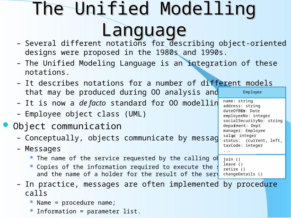
The Unified Modelling LanguageThe Unified Modelling Language– Several different notations for describing object-oriented designs were proposed
in the 1980s and 1990s.
– The Unified Modeling Language is an integration of these notations.
– It describes notations for a number of different models that may be produced during OO analysis and design.
– It is now a de facto standard for OO modelling.
– Employee object class (UML)
Object communication– Conceptually, objects communicate by message passing.
– Messages The name of the service requested by the calling object; Copies of the information required to execute the service
and the name of a holder for the result of the service.
– In practice, messages are often implemented by procedure calls Name = procedure name; Information = parameter list.
Employee
name: stringaddress: stringdateOfBirth: DateemployeeNo: integersocialSecurityNo: stringdepartment: Deptmanager: Employeesalary: integerstatus: {current, left, retired}taxCode: integer. . .
join ()leave ()retire ()changeDetails ()

Message examplesMessage examples
Generalisation and inheritance
– Objects are members of classes that define attribute types and operations.
– Classes may be arranged in a class hierarchy where one class (a super-class) is a generalisation of one or more other classes (sub-classes).
– A sub-class inherits the attributes and operations from its super class and may add new methods or attributes of its own.
– Generalisation in the UML is implemented as inheritance in OO programming languages.
A Generalisation Hierarchy Advantages of Inheritance
– It is an abstraction mechanism which may be used to classify entities.
– It is a reuse mechanism at both the design and the programming level.
– The inheritance graph is a source of organisational knowledge
about domains and systems.
// Call a method associated with a buffer object that returns the next value in the bufferv = circularBuffer.Get () ;
// Call the method associated with a thermostat object that sets the temperature to be maintainedthermostat.setTemp (20) ;
Employee
Programmer
projectprogLanguages
Manager
ProjectManager
budgetsControlled
dateAppointed
projects
Dept.Manager
StrategicManager
dept responsibilities

Problems with InheritanceProblems with Inheritance– Object classes are not self-contained. they cannot be understood without
reference to their super-classes.
– Designers have a tendency to reuse the inheritance graph created during analysis. Can lead to significant inefficiency.
– The inheritance graphs of analysis, design and implementation have different functions and should be separately maintained.
UML Associations– Objects and object classes participate in relationships with other objects and
object classes.
– In the UML, a generalised relationship is indicated by an association.
– Associations may be annotated with information that describes the association.
– Associations are general but may indicate that an attribute of an object is an associated object or that a method relies on an associated object.
An association ModelAn association Model Concurrent Objects
– The nature of objects as self-contained entities make them suitable for concurrent implementation.
– The message-passing model of object communication can be implemented directly if objects are running on separate processors in a distributed system.
Servers and Active Objects– Servers: The object is implemented as a parallel process (server) with entry points corresponding
to object operations. If no calls are made to it, the object suspends itself and waits for further requests for service.
– Active objects: Objects are implemented as parallel processes and the internal object state may be changed by the object itself and not simply by external calls.
Active Transponder Object– Active objects may have their attributes modified by operations but may also
update them autonomously using internal operations.
– A Transponder object broadcasts an aircraft’s position. The position may be updated using a satellite positioning system. The object periodically update the position by triangulation from satellites.
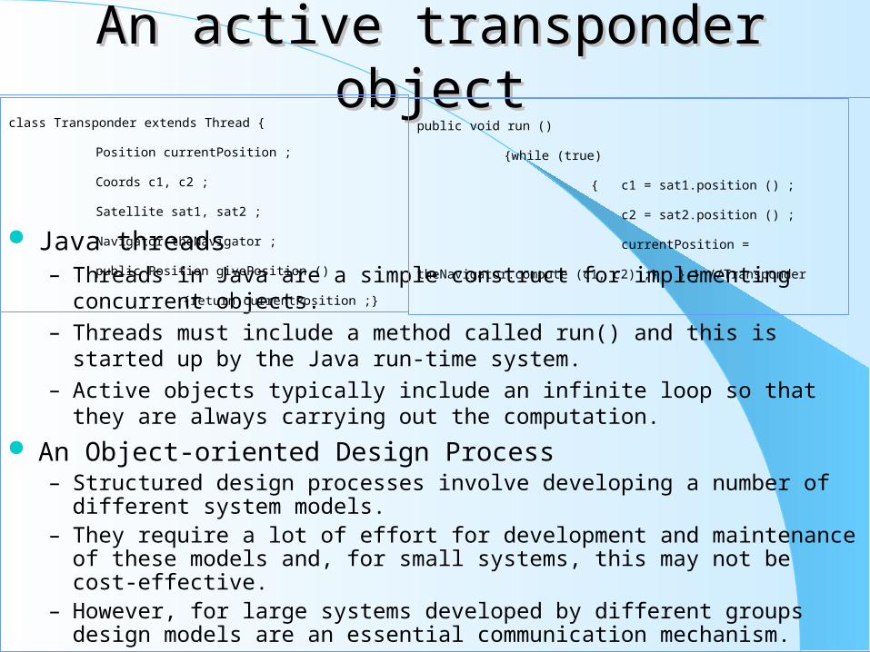
An active transponder objectAn active transponder object
Java threads– Threads in Java are a simple construct for implementing concurrent objects.
– Threads must include a method called run() and this is started up by the Java run-time system.
– Active objects typically include an infinite loop so that they are always carrying out the computation.
An Object-oriented Design Process– Structured design processes involve developing a number of different system
models.– They require a lot of effort for development and maintenance of these models
and, for small systems, this may not be cost-effective.– However, for large systems developed by different groups design models are an
essential communication mechanism.
class Transponder extends Thread {
Position currentPosition ;
Coords c1, c2 ;
Satellite sat1, sat2 ;
Navigator theNavigator ;
public Position givePosition ()
{return currentPosition ;}
public void run ()
{while (true)
{ c1 = sat1.position () ;
c2 = sat2.position () ;
currentPosition = theNavigator.compute (c1,
c2) ;} } } //Transponder
Process StagesProcess Stages– Highlights key activities without being tied to any proprietary process such as
the RUP (Rational Unified Process). Define the context and modes of use of the system; Design the system architecture; Identify the principal system objects; Develop design models; Specify object interfaces.
System context and models of use– Develop an understanding of the relationships between the software being
designed and its external environment
– System context A static model that describes other systems in the environment. Use a subsystem model to show
other systems. Following slide shows the systems around the weather station system.
– Model of system use A dynamic model that describes how the system interacts with its environment. Use use-cases
to show interactions
Use-case ModelsUse-case Models– Use-case models are used to represent each interaction with the
system.
– A use-case model shows the system features as ellipses and the interacting entity as a stick figure.
Architectural design– Once interactions between the system and its environment have been
understood, you use this information for designing the system architecture.
– A layered architecture as discussed in Chapter 11 is appropriate for the weather station
Interface layer for handling communications; Data collection layer for managing instruments; Instruments layer for collecting data.
– There should normally be no more than 7 entities in an architectural model.

Object IdentificationObject Identification– Identifying objects (or object classes) is the most difficult part of
object oriented design.– There is no 'magic formula' for object identification. It relies on
the skill, experience and domain knowledge of system designers.– Object identification is an iterative process. You are unlikely to get
it right first time. Approaches to identification
– Use a grammatical approach based on a natural language description of the system (used in Hood OOD method).
– Base the identification on tangible things in the application domain.
– Use a behavioural approach and identify objects based on what participates in what behaviour.
– Use a scenario-based analysis. The objects, attributes and methods in each scenario are identified.

Design ModelsDesign Models– Design models show the objects and object classes and
relationships between these entities.
– Static models describe the static structure of the system in terms of object classes and relationships.
– Dynamic models describe the dynamic interactions between objects.
Examples of design models– Sub-system models that show logical groupings of objects into
coherent subsystems.– Sequence models that show the sequence of object interactions.– State machine models that show how individual objects change
their state in response to events.– Other models include use-case models, aggregation models,
generalisation models, etc.
Subsystem ModelsSubsystem Models– Shows how the design is organised into logically related groups of
objects.
– In the UML, these are shown using packages - an encapsulation construct. This is a logical model. The actual organisation of objects in the system may be different.
Sequence models– Sequence models show the sequence of object interactions that
take place Objects are arranged horizontally across the top; Time is represented vertically so models are read top to bottom; Interactions are represented by labelled arrows, Different styles of arrow
represent different types of interaction; A thin rectangle in an object lifeline represents the time when the object is
the controlling object in the system.

StatechartsStatecharts– Show how objects respond to different service requests and the
state transitions triggered by these requests If object state is Shutdown then it responds to a Startup() message; In the waiting state the object is waiting for further messages; If reportWeather () then system moves to summarising state; If calibrate () the system moves to a calibrating state; A collecting state is entered when a clock signal is received.
Object interface specification– Object interfaces have to be specified so that the objects and other
components can be designed in parallel.– Designers should avoid designing the interface representation but
should hide this in the object itself.– Objects may have several interfaces which are viewpoints on the
methods provided.– The UML uses class diagrams for interface specification but Java
may also be used.

Key pointsKey points– OOD is an approach to design so that design components have their own private
state and operations.
– Objects should have constructor and inspection operations. They provide services to other objects.
– Objects may be implemented sequentially or concurrently.
– The Unified Modeling Language provides different notations for defining different object models.
– A range of different models may be produced during an object-oriented design process. These include static and dynamic system models.
– Object interfaces should be defined precisely using e.g. a programming language like Java.
– Object-oriented design potentially simplifies system evolution.

Chapter 16: Chapter 16: User Interface DesignUser Interface Design Objectives
– To suggest some general design principles for user interface design– To explain different interaction styles and their use– To explain when to use graphical and textual information
presentation– To explain the principal activities in the user interface design
process– To introduce usability attributes and approaches to system
evaluation Topics covered
– Design issues– The user interface design process– User analysis– User interface prototyping– Interface evaluation 35

The user interfaceThe user interface– User interfaces should be designed to match the skills, experience
and expectations of its anticipated users.– System users often judge a system by its interface rather than its
functionality.– A poorly designed interface can cause a user to make catastrophic
errors.– Poor user interface design is the reason why so many software
systems are never used. Human factors in interface design
– Limited short-term memory People can instantaneously remember about 7 items of information. If you present more than
this, they are more liable to make mistakes.– People make mistakes
When people make mistakes and systems go wrong, inappropriate alarms and messages can increase stress and hence the likelihood of more mistakes.
– People are different People have a wide range of physical capabilities. Designers should not just design for their
own capabilities.– People have different interaction preferences
Some like pictures, some like text.
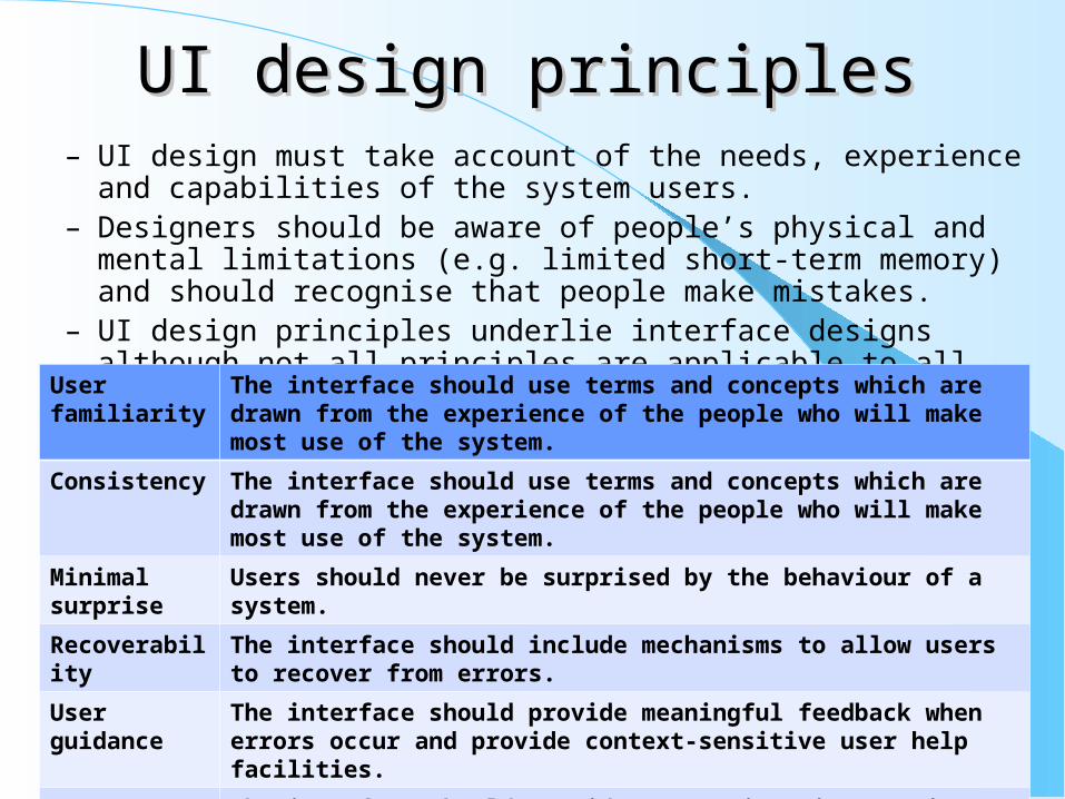
UI design principlesUI design principles– UI design must take account of the needs, experience and capabilities of the
system users.– Designers should be aware of people’s physical and mental limitations (e.g.
limited short-term memory) and should recognise that people make mistakes.– UI design principles underlie interface designs although not all principles are
applicable to all designs.
User familiarity
The interface should use terms and concepts which are drawn from the experience of the people who will make most use of the system.
Consistency The interface should use terms and concepts which are drawn from the experience of the people who will make most use of the system.
Minimal surprise
Users should never be surprised by the behaviour of a system.
Recoverability The interface should include mechanisms to allow users to recover from errors.
User guidance The interface should provide meaningful feedback when errors occur and provide context-sensitive user help facilities.
User diversity The interface should provide appropriate interaction facilities for different types of system user.

Design principlesDesign principles– User familiarity
The interface should be based on user-oriented terms and concepts rather than computer concepts. For example, an office system should use concepts such as letters, documents, folders etc. rather than directories, file identifiers, etc.
– Consistency The system should display an appropriate level of consistency. Commands and menus should
have the same format, command punctuation should be similar, etc.
– Minimal surprise If a command operates in a known way, the user should be able to predict the operation of
comparable commands
– Recoverability The system should provide some resilience to user errors and allow the user to recover from
errors. This might include an undo facility, confirmation of destructive actions, 'soft' deletes, etc.
– User guidance Some user guidance such as help systems, on-line manuals, etc. should be supplied
– User diversity Interaction facilities for different types of user should be supported. For example, some users
have seeing difficulties and so larger text should be available
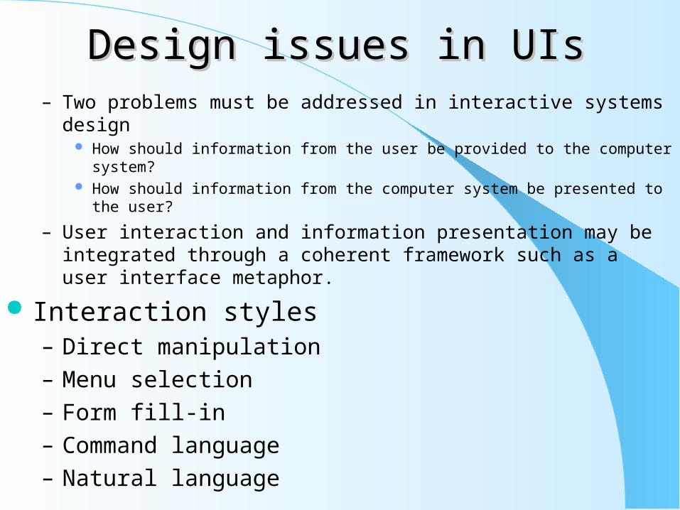
Design issues in UIsDesign issues in UIs– Two problems must be addressed in interactive systems design
How should information from the user be provided to the computer system? How should information from the computer system be presented to the user?
– User interaction and information presentation may be integrated through a coherent framework such as a user interface metaphor.
Interaction styles– Direct manipulation
– Menu selection
– Form fill-in
– Command language
– Natural language

Interaction stylesInteraction styles Interaction
styleMain advantages
Main disadvantages
Application examples
Direct manipulation
Fast and intuitive interactionEasy to learn
May be hard to implement.Only suitable where there is a visual metaphor for tasks and objects.
Video games CAD systems
Menu selection Avoids user errorLittle typing required
Slow for experienced users.Can become complex if many menu options.
Most general-purpose systems
Form fill-in Simple data entryEasy to learnCheckable
Takes up a lot of screen space.Causes problems where user options do not match the form fields.
Stock control, Personal loan processing
Command language
Powerful and flexible
Hard to learn.Poor error management.
Operating systems, Command and control systems
Natural language Accessible to casual users Easily extended
Requires more typing.Natural language understanding systems are unreliable.
Information retrieval systems
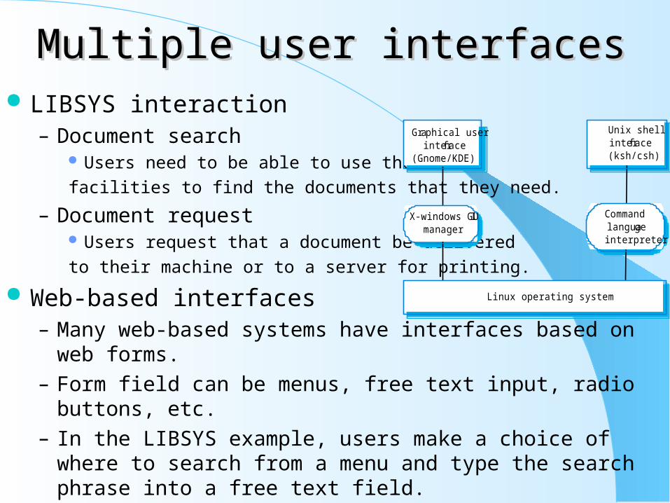
Multiple user interfacesMultiple user interfaces LIBSYS interaction
– Document search Users need to be able to use the search
facilities to find the documents that they need.
– Document request Users request that a document be delivered
to their machine or to a server for printing.
Web-based interfaces– Many web-based systems have interfaces based on web forms.
– Form field can be menus, free text input, radio buttons, etc.
– In the LIBSYS example, users make a choice of where to search from a menu and type the search phrase into a free text field.
Linux operating system
X-windows GUImanager
Graphical userinterface
(Gnome/KDE)
Commandlanguageinterpreter
Unix shellinterface(ksh/csh)

LIBSYS Search FormLIBSYS Search Form Information Presentation
– Information presentation is concerned with presenting system information to system users.
– The information may be presented directly (e.g. text in a word processor) or may be transformed in some way for presentation (e.g. in some graphical form).
– The Model-View-Controller approach is a way of supporting multiple presentations of data.
LIBSYS: Search
Choose collection
Keyword or phrase
Search using
Adjacent words
Search Reset Cancel
All
Title
Yes No
Information tobe displayed
Presentationsoftware
Display

Model-View-ControllerModel-View-Controller Information presentation
– Static information Initialised at the beginning of a session. It does not change during the session. May be either numeric or textual.
– Dynamic information Changes during a session and the changes must be communicated to the
system user. May be either numeric or textual.
Information display factors– Is the user interested in precise information or data relationships?– How quickly do information values change?
Must the change be indicated immediately?– Must the user take some action in response to a change?– Is there a direct manipulation interface?– Is the information textual or numeric? Are relative values
important?
Model methods
Controller methods View methods
Userinputs
view modificationmessages
Model edits
Model queriesand updates
Controller state View state
Model state

Alternative information presentationsAlternative information presentations Analogue or digital presentation?
– Digital presentation Compact - takes up little screen space; Precise values can be communicated.
– Analogue presentation Easier to get an 'at a glance' impression of a value; Possible to show relative values; Easier to see exceptional data values.
Presentation methods Displaying relative values
0
1000
2000
3000
4000
Jan Feb Mar April May June
Jan2842
Feb2851
Mar3164
April2789
May1273
June2835
1
3
4 20 10 20
Dial with needle Pie chart Thermometer Horizontal bar
0 100 200 300 400 0 25 50 75 100
Pressure Temperature

Data visualisationData visualisation– Concerned with techniques for displaying large amounts of information.– Visualisation can reveal relationships between entities and trends in the data.– Possible data visualisations are:
Weather information collected from a number of sources; The state of a telephone network as a linked set of nodes; Chemical plant visualised by showing pressures and temperatures in a linked set of tanks and
pipes; A model of a molecule displayed in 3 dimensions; Web pages displayed as a hyperbolic tree.
Colour displays– Colour adds an extra dimension to an interface and can help the
user understand complex information structures.– Colour can be used to highlight exceptional events.– Common mistakes in the use of colour in
interface design include: The use of colour to communicate meaning; The over-use of colour in the display.

Colour use guidelinesColour use guidelines– Limit the number of colours used and be conservative in their use.– Use colour change to show a change in system status.– Use colour coding to support the task that users are trying to
perform.– Use colour coding in a thoughtful and consistent way.– Be careful about colour pairings.
Error messages– Error message design is critically important.
Poor error messages can mean that a user rejects rather than accepts a system.
– Messages should be polite, concise, consistent and constructive.
– The background and experience of users should be the determining factor in message design.
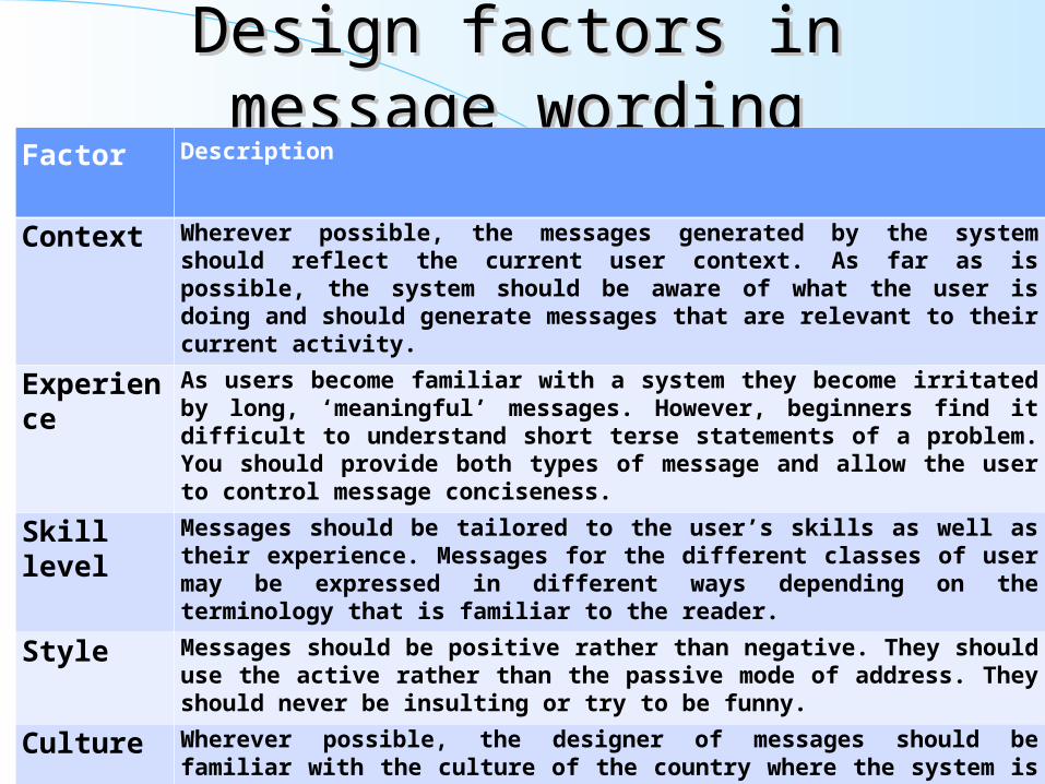
Design factors in message wordingDesign factors in message wording Factor Description
Context Wherever possible, the messages generated by the system should reflect the current user context. As far as is possible, the system should be aware of what the user is doing and should generate messages that are relevant to their current activity.
Experience As users become familiar with a system they become irritated by long, ‘meaningful’ messages. However, beginners find it difficult to understand short terse statements of a problem. You should provide both types of message and allow the user to control message conciseness.
Skill level Messages should be tailored to the user’s skills as well as their experience. Messages for the different classes of user may be expressed in different ways depending on the terminology that is familiar to the reader.
Style Messages should be positive rather than negative. They should use the active rather than the passive mode of address. They should never be insulting or try to be funny.
Culture Wherever possible, the designer of messages should be familiar with the culture of the country where the system is sold. There are distinct cultural differences between Europe, Asia and America. A suitable message for one culture might be unacceptable in another.
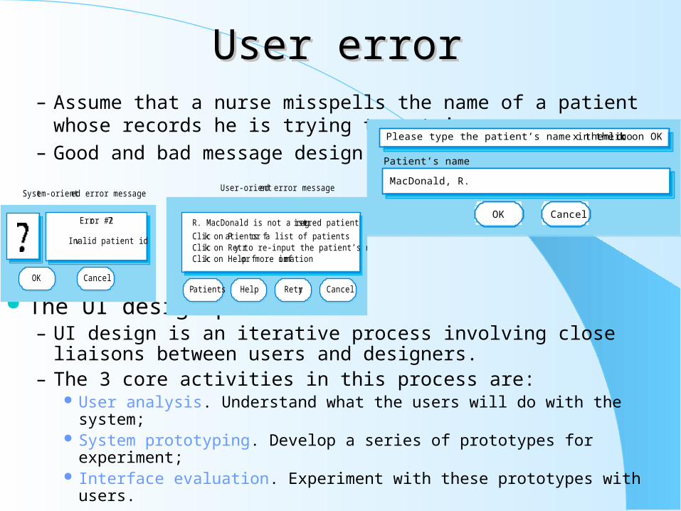
User errorUser error– Assume that a nurse misspells the name of a patient whose records
he is trying to retrieve.
– Good and bad message design
The UI design process– UI design is an iterative process involving close liaisons between
users and designers.– The 3 core activities in this process are:
User analysis. Understand what the users will do with the system; System prototyping. Develop a series of prototypes for experiment; Interface evaluation. Experiment with these prototypes with users.
Please type the patient’s name in the box then click on OK
MacDonald, R.
OK Cancel
Patient’s name
Error #27
Invalid patient id
OK Cancel
System-oriented error messageUser-oriented error message
R. MacDonald is not a reg istered patient
Click on Patients for a list of patientsClick on Retry to re-input the patient’s nameClick on Help for more information
Patients Help Retry Cancel

The design processThe design process User analysis
– If you don’t understand what the users want to do with a system, you have no realistic prospect of designing an effective interface.
– User analyses have to be described in terms that users and other designers can understand.
– Scenarios where you describe typical episodes of use, are one way of describing these analyses.
Executableprototype
Designprototype
Produce paper-based design
prototype
Producedynamic design
prototype
Evaluate designwith end-users
Implementfinal userinterface
Evaluate designwith end-users
Analyse andunderstand
user activities

User interaction scenarioUser interaction scenario Requirements from the scenario
– Users may not be aware of appropriate search terms so need a way of helping them choose terms.
– Users have to be able to select collections to search.
– Users need to be able to carry out searches and request copies of relevant material.
Analysis techniques– Task analysis
Models the steps involved in completing a task.
– Interviewing and questionnaires Asks the users about the work they do.
– Ethnography Observes the user at work.
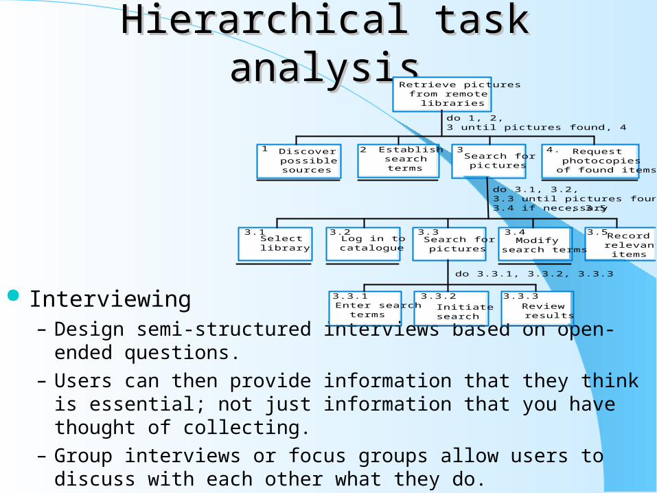
Hierarchical task analysisHierarchical task analysis
Interviewing– Design semi-structured interviews based on open-ended questions.
– Users can then provide information that they think is essential; not just information that you have thought of collecting.
– Group interviews or focus groups allow users to discuss with each other what they do.
Retrieve picturesfrom remote
libraries
Discoverpossiblesources
Establishsearchterms
Search forpictures
Requestphotocopies
of found items
1 2 3 4.
Selectlibrary
Log in tocatalogue
Search forpictures
Modifysearch terms
Recordrelevantitems
3.1 3.2 3.3 3.4 3.5
Enter searchterms
Initiatesearch
Reviewresults
3.3.1 3.3.2 3.3.3
do 1, 2,3 until pictures found, 4
do 3.1, 3.2,3.3 until pictures found,3.4 if necessary, 3.5
do 3.3.1, 3.3.2, 3.3.3

EthnographyEthnography– Involves an external observer watching users at work and
questioning them in an unscripted way about their work.
– Valuable because many user tasks are intuitive and they find these very difficult to describe and explain.
– Also helps understand the role of social and organisational influences on work.
User interface prototyping– The aim of prototyping is to allow users to gain direct experience
with the interface.– Without such direct experience, it is impossible to judge the
usability of an interface.– Prototyping may be a two-stage process:
Early in the process, paper prototypes may be used; The design is then refined and increasingly sophisticated automated
prototypes are then developed.

Paper prototypingPaper prototyping– Work through scenarios using sketches of the interface.
– Use a storyboard to present a series of interactions with the system.
– Paper prototyping is an effective way of getting user reactions to a design proposal.
Prototyping techniques– Script-driven prototyping
Develop a set of scripts and screens using a tool such as Macromedia Director. When the user interacts with these, the screen changes to the next display.
– Visual programming Use a language designed for rapid development such as Visual Basic. See
Chapter 17.
– Internet-based prototyping Use a web browser and associated scripts.
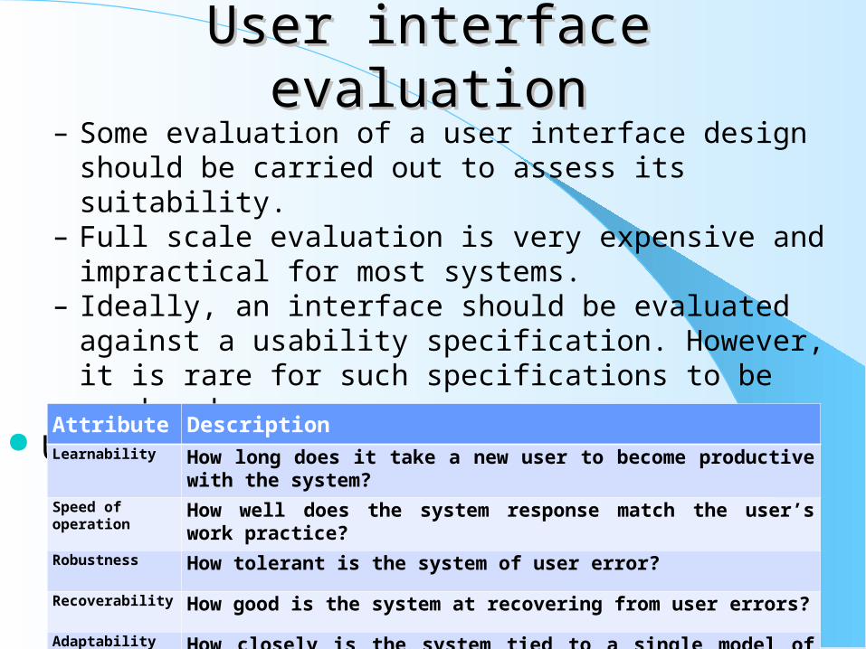
User interface evaluationUser interface evaluation– Some evaluation of a user interface design should be carried out to
assess its suitability.– Full scale evaluation is very expensive and impractical for most
systems.– Ideally, an interface should be evaluated against a usability
specification. However, it is rare for such specifications to be produced.
Usability attributesAttribute DescriptionLearnability How long does it take a new user to become productive with the system?
Speed of operation How well does the system response match the user’s work practice?
Robustness How tolerant is the system of user error?
Recoverability How good is the system at recovering from user errors?
Adaptability How closely is the system tied to a single model of work?
Simple evaluation techniquesSimple evaluation techniques– Questionnaires for user feedback.
– Video recording of system use and subsequent tape evaluation.
– Instrumentation of code to collect information about facility use and user errors.
– The provision of code in the software to collect on-line user feedback.

Key points– User interface design principles should help guide the design of
user interfaces.– Interaction styles include direct manipulation, menu systems form
fill-in, command languages and natural language.– Graphical displays should be used to present trends and
approximate values. Digital displays when precision is required.– Colour should be used sparingly and consistently.– The user interface design process involves user analysis, system
prototyping and prototype evaluation.– The aim of user analysis is to sensitise designers to the ways in
which users actually work.– UI prototyping should be a staged process with early paper
prototypes used as a basis for automated prototypes of the interface.
– The goals of UI evaluation are to obtain feedback on how to improve the interface design and to assess if the interface meets its usability requirements.

Chapter 17: Chapter 17: Rapid Software Rapid Software DevelopmentDevelopment
Objectives– To explain how an iterative, incremental development process
leads to faster delivery of more useful software– To discuss the essence of agile development methods– To explain the principles and practices of extreme programming– To explain the roles of prototyping in the software process
Topics covered– Agile methods
– Extreme programming
– Rapid application development
– Software prototyping
57
Rapid software developmentRapid software development– Because of rapidly changing business environments, businesses
have to respond to new opportunities and competition.– This requires software and rapid development and delivery is not
often the most critical requirement for software systems.– Businesses may be willing to accept lower quality software if rapid
delivery of essential functionality is possible.
Requirements– Because of the changing environment, it is often impossible to
arrive at a stable, consistent set of system requirements.
– Therefore a waterfall model of development is impractical and an approach to development based on iterative specification and delivery is the only way to deliver software quickly.

Characteristics of RAD processesCharacteristics of RAD processes– The processes of specification, design and implementation are
concurrent. There is no detailed specification and design documentation is minimised.
– The system is developed in a series of increments. End users evaluate each increment and make proposals for later increments.
– System user interfaces are usually developed using an interactive development system.
An iterative development process
Validateincrement
Build systemincrement
Specify systemincrement
Design systemarchitecture
Define systemdeliverables
Systemcomplete?
Integrateincrement
Validatesystem
Deliver finalsystem
YES
NO
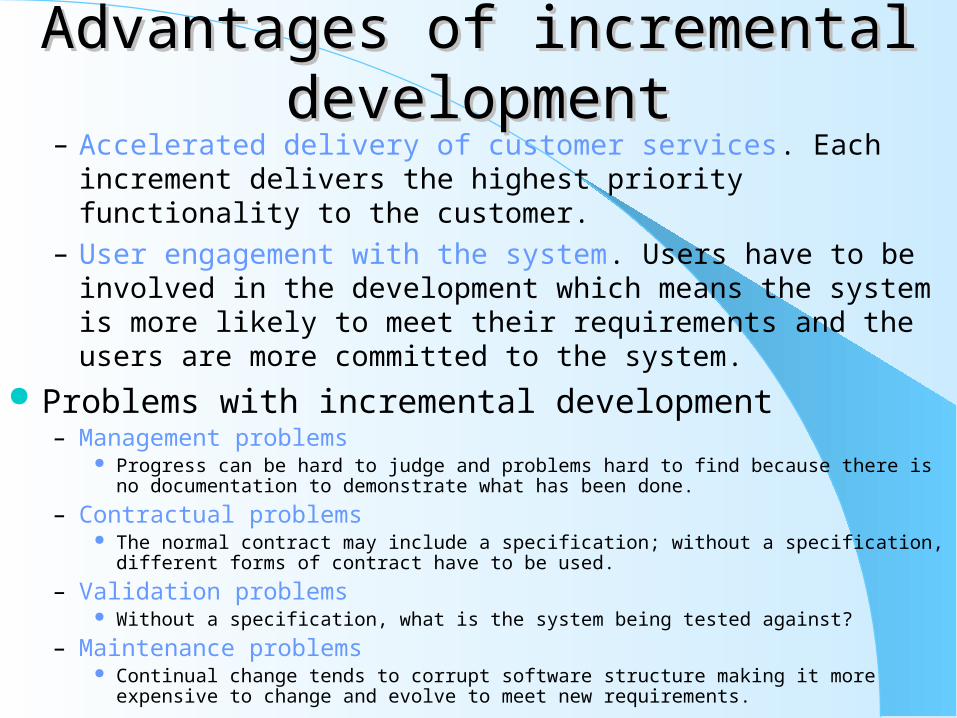
Advantages of incremental Advantages of incremental developmentdevelopment
– Accelerated delivery of customer services. Each increment delivers the highest priority functionality to the customer.
– User engagement with the system. Users have to be involved in the development which means the system is more likely to meet their requirements and the users are more committed to the system.
Problems with incremental development– Management problems
Progress can be hard to judge and problems hard to find because there is no documentation to demonstrate what has been done.
– Contractual problems The normal contract may include a specification; without a specification, different forms of
contract have to be used.
– Validation problems Without a specification, what is the system being tested against?
– Maintenance problems Continual change tends to corrupt software structure making it more expensive to change and
evolve to meet new requirements.
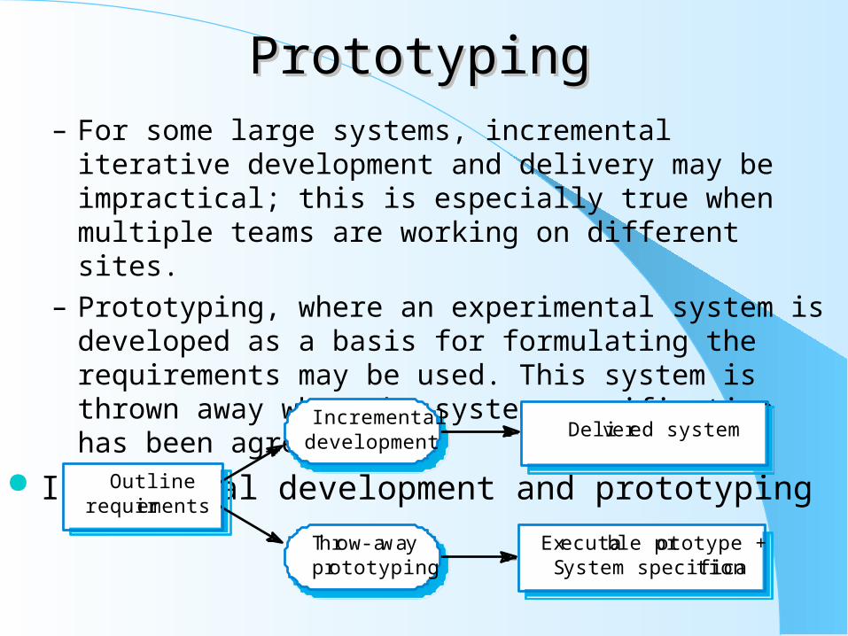
PrototypingPrototyping– For some large systems, incremental iterative development and
delivery may be impractical; this is especially true when multiple teams are working on different sites.
– Prototyping, where an experimental system is developed as a basis for formulating the requirements may be used. This system is thrown away when the system specification has been agreed.
Incremental development and prototyping
Incrementaldevelopment
Throw-awayprototyping
Delivered system
Executable prototype +System specification
Outlinerequirements
Conflicting objectivesConflicting objectives– The objective of incremental development is to deliver a working
system to end-users. The development starts with those requirements which are best understood.
– The objective of throw-away prototyping is to validate or derive the system requirements. The prototyping process starts with those requirements which are poorly understood.
Agile methods– Dissatisfaction with the overheads involved in design methods led to the
creation of agile methods. These methods: Focus on the code rather than the design; Are based on an iterative approach to software development; Are intended to deliver working software quickly and evolve this quickly to meet changing
requirements.
– Agile methods are probably best suited to small/medium-sized business systems or PC products.

Principles of agile methodsPrinciples of agile methods
Principle Description
Customer involvement
The customer should be closely involved throughout the development process. Their role is provide and prioritise new system requirements and to evaluate the iterations of the system.
Incremental delivery
The software is developed in increments with the customer specifying the requirements to be included in each increment.
People not process
The skills of the development team should be recognised and exploited. The team should be left to develop their own ways of working without prescriptive processes.
Embrace change
Expect the system requirements to change and design the system so that it can accommodate these changes.
Maintain simplicity
Focus on simplicity in both the software being developed and in the development process used. Wherever possible, actively work to eliminate complexity from the system.

Problems with agile methodsProblems with agile methods– It can be difficult to keep the interest of customers who are
involved in the process.– Team members may be unsuited to the intense involvement that
characterises agile methods.– Prioritising changes can be difficult where there are multiple
stakeholders.– Maintaining simplicity requires extra work.– Contracts may be a problem as with other approaches to iterative
development. Extreme programming
– Perhaps the best-known and most widely used agile method.– Extreme Programming (XP) takes an ‘extreme’ approach to
iterative development. New versions may be built several times per day; Increments are delivered to customers every 2 weeks; All tests must be run for every build and the build is only accepted if tests
run successfully.
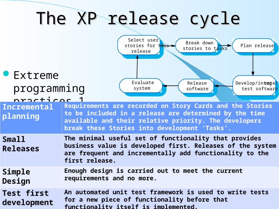
The XP release cycleThe XP release cycle
Extreme programming practices 1
Break downstories to tasks
Select userstories for this
releasePlan release
Releasesoftware
Evaluatesystem
Develop/integrate/test software
Incremental planning
Requirements are recorded on Story Cards and the Stories to be included in a release are determined by the time available and their relative priority. The developers break these Stories into development ‘Tasks’.
Small Releases The minimal useful set of functionality that provides business value is developed first. Releases of the system are frequent and incrementally add functionality to the first release.
Simple Design Enough design is carried out to meet the current requirements and no more.
Test first development
An automated unit test framework is used to write tests for a new piece of functionality before that functionality itself is implemented.
Refactoring All developers are expected to refactor the code continuously as soon as possible code improvements are found. This keeps the code simple and maintainable.

Extreme programming practices 2Extreme programming practices 2
XP and agile principles– Incremental development is supported through small, frequent
system releases.– Customer involvement means full-time customer engagement with
the team.– People not process through pair programming, collective
ownership and a process that avoids long working hours.– Change supported through regular system releases.– Maintaining simplicity through constant refactoring of code.
Pair Programming Developers work in pairs, checking each other’s work and providing the support to always do a good job.
Collective Ownership
The pairs of developers work on all areas of the system, so that no islands of expertise develop and all the developers own all the code. Anyone can change anything.
Continuous Integration
As soon as work on a task is complete it is integrated into the whole system. After any such integration, all the unit tests in the system must pass.
Sustainable pace Large amounts of over-time are not considered acceptable as the net effect is often to reduce code quality and medium term productivity
On-site Customer A representative of the end-user of the system (the Customer) should be available full time for the use of the XP team. In an extreme programming process, the customer is a member of the development team and is responsible for bringing system requirements to the team for implementation.

Requirements scenariosRequirements scenarios– In XP, user requirements are expressed as scenarios or user stories.
– These are written on cards and the development team break them down into implementation tasks. These tasks are the basis of schedule and cost estimates.
– The customer chooses the stories for inclusion in the next release based on their priorities and the schedule estimates.
XP and change– Conventional wisdom in software engineering is to design for
change. It is worth spending time and effort anticipating changes as this reduces costs later in the life cycle.
– XP, however, maintains that this is not worthwhile as changes cannot be reliably anticipated.
– Rather, it proposes constant code improvement (refactoring) to make changes easier when they have to be implemented.
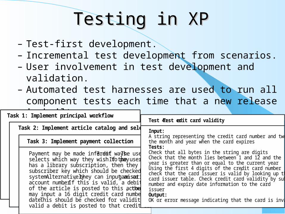
Testing in XPTesting in XP– Test-first development.– Incremental test development from scenarios.– User involvement in test development and validation.– Automated test harnesses are used to run all component tests each
time that a new release is built. Task cards for document downloading
Task 1: Implement principal workflow
Task 2: Implement article catalog and selection
Task 3: Implement payment collection
Payment may be made in 3 different ways. The userselects which way they wish to pay. If the userhas a library subscription, then they can input thesubscriber key which should be checked by thesystem. Alternatively, they can input an organisationalaccount number. If this is valid, a debit of the costof the article is posted to this account. Finally, theymay input a 16 digit credit card number and expirydate. This should be checked for validity and, ifvalid a debit is posted to that credit card account.
Test 4: Test credit card validity
Input:A string representing the credit card number and two integers representingthe month and year when the card expiresTests:Check that all bytes in the string are digitsCheck that the month lies between 1 and 12 and theyear is greater than or equal to the current year.Using the first 4 digits of the credit card number,check that the card issuer is valid by looking up thecard issuer table. Check credit card validity by submitting the cardnumber and expiry date information to the cardissuerOutput:OK or error message indicating that the card is invalid
Test-first developmentTest-first development– Writing tests before code clarifies the requirements to be
implemented.– Tests are written as programs rather than data so that they can be
executed automatically. The test includes a check that it has executed correctly.
– All previous and new tests are automatically run when new functionality is added. Thus checking that the new functionality has not introduced errors.
Pair programming– In XP, programmers work in pairs, sitting together to develop
code.– This helps develop common ownership of code and spreads
knowledge across the team.– It serves as an informal review process as each line of code is
looked at by more than 1 person.– It encourages refactoring as the whole team can benefit from this.– Measurements suggest that development productivity with pair
programming is similar to that of two people working independently.
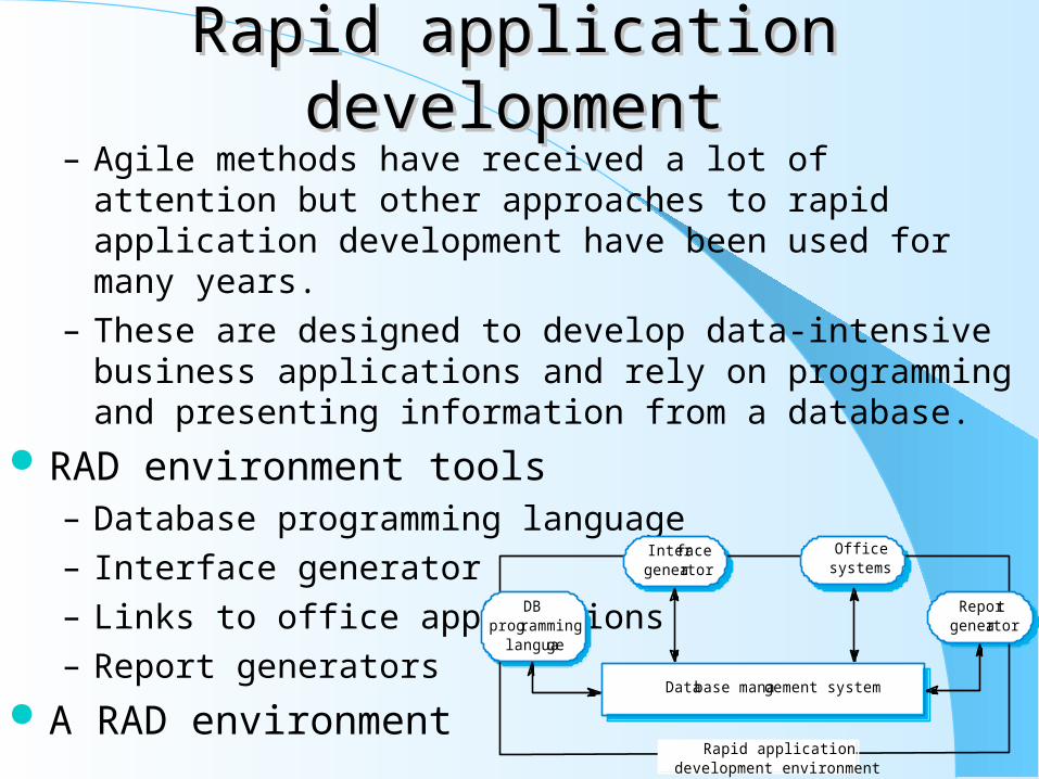
Rapid application developmentRapid application development– Agile methods have received a lot of attention but other
approaches to rapid application development have been used for many years.
– These are designed to develop data-intensive business applications and rely on programming and presenting information from a database.
RAD environment tools– Database programming language
– Interface generator
– Links to office applications
– Report generators
A RAD environment
DBprogramming
language
Interfacegenerator
Officesystems
Reportgenerator
Database management system
Rapid applicationdevelopment environment
Interface generationInterface generation– Many applications are based around complex forms and
developing these forms manually is a time-consuming activity.– RAD environments include support for screen generation
including: Interactive form definition using drag and drop techniques; Form linking where the sequence of forms to be presented is specified; Form verification where allowed ranges in form fields is defined.
Visual programming– Scripting languages such as Visual Basic support visual
programming where the prototype is developed by creating a user interface from standard items and associating components with these items
– A large library of components exists to support this type of development
– These may be tailored to suit the specific application requirements
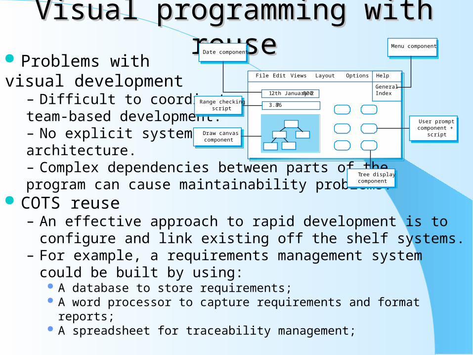
Visual programming with reuseVisual programming with reuse Problems with visual development
– Difficult to coordinate team-based development.– No explicit system architecture.– Complex dependencies between parts of the program can cause maintainability problems.
COTS reuse– An effective approach to rapid development is to configure and
link existing off the shelf systems.– For example, a requirements management system could be built by
using: A database to store requirements; A word processor to capture requirements and format reports; A spreadsheet for traceability management;
File Edit Views Layout Options Help
GeneralIndex
Menu componentDate component
Range checkingscript
Tree displaycomponent
Draw canvascomponent
User promptcomponent +
script
12th January 2000
3.876

Compound documentsCompound documents– For some applications, a prototype can be created by developing a
compound document.– This is a document with active elements (such as a spreadsheet)
that allow user computations.– Each active element has an associated application which is
invoked when that element is selected.– The document itself is the integrator for the different applications.
Application linking
Word processor Spreadsheet Audio player
Text 1 Text 2 Text 3
Text 5
Table 1 Sound 1
Text 4Table 2 Sound 2
Compound document

Software prototypingSoftware prototyping– A prototype is an initial version of a system used to demonstrate
concepts and try out design options.– A prototype can be used in:
The requirements engineering process to help with requirements elicitation and validation;
In design processes to explore options and develop a UI design; In the testing process to run back-to-back tests.
Benefits of prototyping– Improved system usability.– A closer match to users’ real needs.– Improved design quality.– Improved maintainability.– Reduced development effort.
Back to back testing
Test data
Resultscomparator
Systemprototype
Applicationsystem
Differencereport

The prototyping processThe prototyping process
Throw-away prototypes– Prototypes should be discarded after development as they are not a
good basis for a production system: It may be impossible to tune the system to meet non-functional
requirements; Prototypes are normally undocumented; The prototype structure is usually degraded through rapid change; The prototype probably will not meet normal organisational quality
standards.
Establishprototypeobjectives
Defineprototype
functionality
Developprototype
Evaluateprototype
Prototypingplan
Outlinedefinition
Executableprototype
Evaluationreport

Key points– An iterative approach to software development leads to faster
delivery of software.– Agile methods are iterative development methods that aim to
reduce development overhead and so produce software faster.– Extreme programming includes practices such as systematic
testing, continuous improvement and customer involvement.– The approach to testing in XP is a particular strength where
executable tests are developed before the code is written.– Rapid application development environments include database
programming languages, form generation tools and links to office applications.
– A throw-away prototype is used to explore requirements and design options.
– When implementing a throw-away prototype, start with the requirements you least understand; in incremental development, start with the best-understood requirements.
Chapter 18: Chapter 18: Software ReuseSoftware Reuse Objectives
– To explain the benefits of software reuse and some reuse problems– To discuss several different ways to implement software reuse– To explain how reusable concepts can be represented as patterns or embedded
in program generators– To discuss COTS reuse– To describe the development of software product lines
Topics covered– The reuse landscape
– Design patterns
– Generator based reuse
– Application frameworks
– Application system reuse77

Software reuseSoftware reuse– In most engineering disciplines, systems are designed by
composing existing components that have been used in other systems.
– Software engineering has been more focused on original development but it is now recognised that to achieve better software, more quickly and at lower cost, we need to adopt a design process that is based on systematic software reuse.
Reuse-based software engineering– Application system reuse
The whole of an application system may be reused either by incorporating it without change into other systems (COTS reuse) or by developing application families.
– Component reuse Components of an application from sub-systems to single objects may be
reused. Covered in Chapter 19.– Object and function reuse
Software components that implement a single well-defined object or function may be reused.
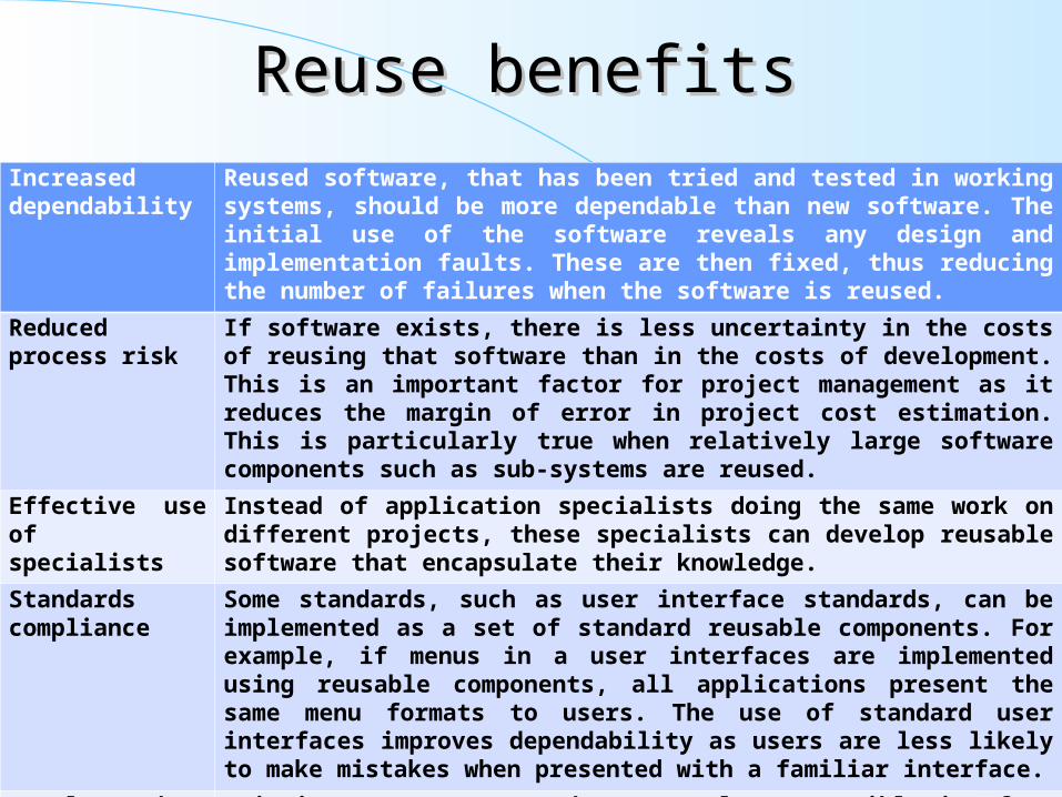
Reuse benefitsReuse benefits Increased dependability
Reused software, that has been tried and tested in working systems, should be more dependable than new software. The initial use of the software reveals any design and implementation faults. These are then fixed, thus reducing the number of failures when the software is reused.
Reduced process risk
If software exists, there is less uncertainty in the costs of reusing that software than in the costs of development. This is an important factor for project management as it reduces the margin of error in project cost estimation. This is particularly true when relatively large software components such as sub-systems are reused.
Effective use of specialists
Instead of application specialists doing the same work on different projects, these specialists can develop reusable software that encapsulate their knowledge.
Standards compliance
Some standards, such as user interface standards, can be implemented as a set of standard reusable components. For example, if menus in a user interfaces are implemented using reusable components, all applications present the same menu formats to users. The use of standard user interfaces improves dependability as users are less likely to make mistakes when presented with a familiar interface.
Accelerated development
Bringing a system to market as early as possible is often more important than overall development costs. Reusing software can speed up system production because both development and validation time should be reduced.

Reuse problemsReuse problems Increased maintenance costs
If the source code of a reused software system or component is not available then maintenance costs may be increased as the reused elements of the system may become increasingly incompatible with system changes.
Lack of tool support CASE toolsets may not support development with reuse. It may be difficult or impossible to integrate these tools with a component library system. The software process assumed by these tools may not take reuse into account.
Not-invented-here syndrome
Some software engineers sometimes prefer to re-write components as they believe that they can improve on the reusable component. This is partly to do with trust and partly to do with the fact that writing original software is seen as more challenging than reusing other people’s software.
Creating and maintaining a component library
Populating a reusable component library and ensuring the software developers can use this library can be expensive. Our current techniques for classifying, cataloguing and retrieving software components are immature.
Finding, understanding and adapting reusable components
Software components have to be discovered in a library, understood and, sometimes, adapted to work in a new environment. Engineers must be reasonably confident of finding a component in the library before they will make routinely include a component search as part of their normal development process.

The reuse landscapeThe reuse landscape– Although reuse is often simply thought of as the reuse of system
components, there are many different approaches to reuse that may be used.
– Reuse is possible at a range of levels from simple functions to complete application systems.
– The reuse landscape covers the range of possible reuse techniques.
Designpatterns
Component-baseddevelopment
Componentframeworks
Service-orientedsystems
COTSintegration
Applicationproduct lines
Legacy systemwrapping
Programlibraries
Programgenerators
Aspect-orientedsoftware development
Configurable verticalapplications

Reuse approachesReuse approaches
Design patterns Generic abstractions that occur across applications are represented as design patterns that show abstract and concrete objects and interactions.
Component-based development
Systems are developed by integrating components (collections of objects) that conform to component-model standards. This is covered in Chapter 19.
Application frameworks
Collections of abstract and concrete classes that can be adapted and extended to create application systems.
Legacy system wrapping
Legacy systems (see Chapter 2) that can be ‘wrapped’ by defining a set of interfaces and providing access to these legacy systems through these interfaces.
Service-oriented systems
Systems are developed by linking shared services that may be externally provided.
Application product lines
An application type is generalised around a common architecture so that it can be adapted in different ways for different customers.
COTS integration Systems are developed by integrating existing application systems.
Configurable vertical applications
A generic system is designed so that it can be configured to the needs of specific system customers.
Program libraries Class and function libraries implementing commonly-used abstractions are available for reuse.
Program generators A generator system embeds knowledge of a particular types of application and can generate systems or system fragments in that domain.
Aspect-oriented software development
Shared components are woven into an application at different places when the program is compiled.

Reuse planning factorsReuse planning factors– The development schedule for the software.– The expected software lifetime.– The background, skills and experience of the development team.– The criticality of the software and its non-functional requirements.– The application domain.– The execution platform for the software.
Concept reuse– When you reuse program or design components, you have to
follow the design decisions made by the original developer of the component.
– This may limit the opportunities for reuse.– However, a more abstract form of reuse is concept reuse when a
particular approach is described in an implementation independent way and an implementation is then developed.
– The two main approaches to concept reuse are: Design patterns; Generative programming.

Design patternsDesign patterns– A design pattern is a way of reusing abstract knowledge about a
problem and its solution.– A pattern is a description of the problem and the essence of its
solution.– It should be sufficiently abstract to be reused in different settings.– Patterns often rely on object characteristics such as inheritance and
polymorphism. Pattern elements
– Name: A meaningful pattern identifier.– Problem description.– Solution description: Not a concrete design but a template for a
design solution that can be instantiated in different ways.– Consequences: The results and trade-offs of applying the pattern.

The Observer patternThe Observer pattern– Description: Separates the display of object state from the object
itself.– Problem description: Used when multiple displays of state are
needed.– Solution description: See slide with UML description.– Consequences: Optimisations to enhance display performance are
impractical. Generator-based reuse
– Program generators involve the reuse of standard patterns and algorithms.
– These are embedded in the generator and parameterised by user commands. A program is then automatically generated.
– Generator-based reuse is possible when domain abstractions and their mapping to executable code can be identified.
– A domain specific language is used to compose and control these abstractions.
Types of program generatorTypes of program generator– Types of program generator
Application generators for business data processing; Parser and lexical analyser generators for language processing; Code generators in CASE tools.
– Generator-based reuse is very cost-effective but its applicability is limited to a relatively small number of application domains.
– It is easier for end-users to develop programs using generators compared to other component-based approaches to reuse.
Aspect-oriented development– Aspect-oriented development addresses a major software engineering problem -
the separation of concerns.– Concerns are often not simply associated with application functionality but are
cross-cutting - e.g. all components may monitor their own operation, all components may have to maintain security, etc.
– Cross-cutting concerns are implemented as aspects and are dynamically woven into a program. The concern code is reuse and the new system is generated by the aspect weaver.

Application frameworksApplication frameworks– Frameworks are a sub-system design made up of a collection of
abstract and concrete classes and the interfaces between them.– The sub-system is implemented by adding components to fill in
parts of the design and by instantiating the abstract classes in the framework.
– Frameworks are moderately large entities that can be reused. Framework classes
– System infrastructure frameworks Support the development of system infrastructures such as communications,
user interfaces and compilers.– Middleware integration frameworks
Standards and classes that support component communication and information exchange.
– Enterprise application frameworks Support the development of specific types of application such as
telecommunications or financial systems.
Extending frameworksExtending frameworks– Frameworks are generic and are extended to create a more specific
application or sub-system.– Extending the framework involves
Adding concrete classes that inherit operations from abstract classes in the framework;
Adding methods that are called in response to events that are recognised by the framework.
– Problem with frameworks is their complexity which means that it takes a long time to use them effectively.
Model-view controller– System infrastructure framework for GUI design.– Allows for multiple presentations of an object and separate
interactions with these presentations.– MVC framework involves the instantiation of a number of patterns
(as discussed earlier under concept reuse).

Application system reuseApplication system reuse– Involves the reuse of entire application systems either by
configuring a system for an environment or by integrating two or more systems to create a new application.
– Two approaches covered here: COTS product integration; Product line development.
COTS product reuse– COTS - Commercial Off-The-Shelf systems.– COTS systems are usually complete application systems that offer
an API (Application Programming Interface).– Building large systems by integrating COTS systems is now a
viable development strategy for some types of system such as E-commerce systems.
– The key benefit is faster application development and, usually, lower development costs.

COTS design choicesCOTS design choices– Which COTS products offer the most appropriate functionality?
There may be several similar products that may be used.
– How will data be exchanged? Individual products use their own data structures and formats.
– What features of the product will actually be used? Most products have more functionality than is needed. You should try to
deny access to unused functionality.
COTS products reused– On the client, standard e-mail and web browsing programs are
used.
– On the server, an e-commerce platform has to be integrated with an existing ordering system.
This involves writing an adaptor so that they can exchange data. An e-mail system is also integrated to generate e-mail for clients. This also
requires an adaptor to receive data from the ordering and invoicing system.
COTS system integration problemsCOTS system integration problems– Lack of control over functionality and performance
COTS systems may be less effective than they appear– Problems with COTS system inter-operability
Different COTS systems may make different assumptions that means integration is difficult
– No control over system evolution COTS vendors not system users control evolution
– Support from COTS vendors COTS vendors may not offer support over the lifetime of the product
Software product lines– Software product lines or application families are applications with generic
functionality that can be adapted and configured for use in a specific context.
– Adaptation may involve: Component and system configuration; Adding new components to the system; Selecting from a library of existing components; Modifying components to meet new requirements.


COTS product specialisationCOTS product specialisation– Platform specialisation
Different versions of the application are developed for different platforms.– Environment specialisation
Different versions of the application are created to handle different operating environments e.g. different types of communication equipment.
– Functional specialisation Different versions of the application are created for customers with different
requirements.– Process specialisation
Different versions of the application are created to support different business processes.
COTS configuration– Deployment time configuration
A generic system is configured by embedding knowledge of the customer’s requirements and business processes. The software itself is not changed.
– Design time configuration A common generic code is adapted and changed according to the
requirements of particular customers.

ERP systemsERP systems– An Enterprise Resource Planning (ERP) system is a generic
system that supports common business processes such as ordering and invoicing, manufacturing, etc.
– These are very widely used in large companies - they represent probably the most common form of software reuse.
– The generic core is adapted by including modules and by incorporating knowledge of business processes and rules.
Design time configuration– Software product lines that are configured at design time are
instantiations of generic application architectures as discussed in Chapter 13.
– Generic products usually emerge after experience with specific products.

Product line architecturesProduct line architectures– Architectures must be structured in such a way to separate
different sub-systems and to allow them to be modified.– The architecture should also separate entities and their descriptions
and the higher levels in the system access entities through descriptions rather than directly.
Product instance development– Elicit stakeholder requirements
Use existing family member as a prototype– Choose closest-fit family member
Find the family member that best meets the requirements– Re-negotiate requirements
Adapt requirements as necessary to capabilities of the software– Adapt existing system
Develop new modules and make changes for family member– Deliver new family member
Document key features for further member development
Key points– Advantages of reuse are lower costs, faster software development
and lower risks.– Design patterns are high-level abstractions that document
successful design solutions.– Program generators are also concerned with software reuse - the
reusable concepts are embedded in a generator system.– Application frameworks are collections of concrete and abstract
objects that are designed for reuse through specialisation.– COTS product reuse is concerned with the reuse of large, off-the-
shelf systems.– Problems with COTS reuse include lack of control over
functionality, performance, and evolution and problems with inter-operation.
– ERP systems are created by configuring a generic system with information about a customer’s business.
– Software product lines are related applications developed around a common core of shared functionality.

Chapter 23: Chapter 23: Software TestingSoftware Testing Objectives
– To discuss the distinctions between validation testing and defect testing
– To describe the principles of system and component testing
– To describe strategies for generating system test cases
– To understand the essential characteristics of tool used for test automation
Topics covered– System testing
– Component testing
– Test case design
– Test automation100

The testing processThe testing process– Component testing
Testing of individual program components; Usually the responsibility of the component developer (except sometimes for critical
systems); Tests are derived from the developer’s experience.
– System testing Testing of groups of components integrated to create a system or sub-system; The responsibility of an independent testing team; Tests are based on a system
Testing phases Defect testing
– The goal of defect testing is to discover defects in programs– A successful defect test is a test which causes a program to behave
in an anomalous way– Tests show the presence not the absence of defects
Componenttesting
Systemtesting
Software developer Independent testing team
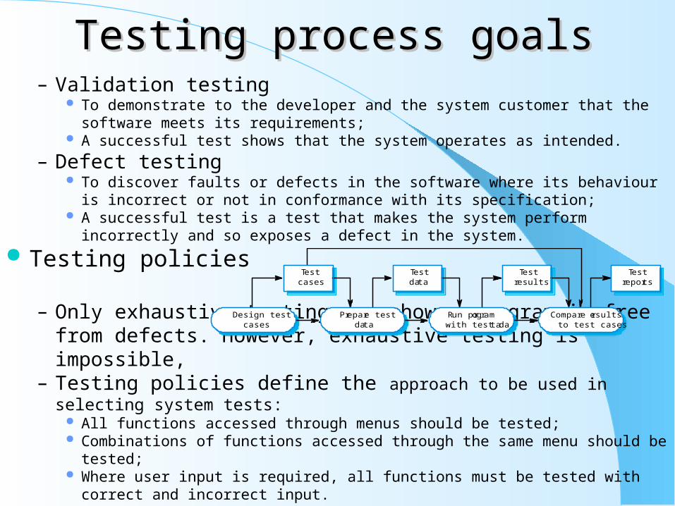
Testing process goalsTesting process goals– Validation testing
To demonstrate to the developer and the system customer that the software meets its requirements;
A successful test shows that the system operates as intended.
– Defect testing To discover faults or defects in the software where its behaviour is incorrect or not in
conformance with its specification; A successful test is a test that makes the system perform incorrectly and so exposes a
defect in the system.
Testing policies
– Only exhaustive testing can show a program is free from defects. However, exhaustive testing is impossible,
– Testing policies define the approach to be used in selecting system tests: All functions accessed through menus should be tested; Combinations of functions accessed through the same menu should be tested; Where user input is required, all functions must be tested with correct and incorrect
input.
Design testcases
Prepare testdata
Run programwith test data
Compare resultsto test cases
Testcases
Testdata
Testresults
Testreports

System testingSystem testing– Involves integrating components to create a system or sub-system.– May involve testing an increment to be delivered to the customer.– Two phases:
Integration testing - the test team have access to the system source code. The system is tested as components are integrated.
Release testing - the test team test the complete system to be delivered as a black-box.
Integration testing– Involves building a system from its components and testing it for
problems that arise from component interactions.– Top-down integration
Develop the skeleton of the system and populate it with components.– Bottom-up integration
Integrate infrastructure components then add functional components.– To simplify error localisation, systems should be incrementally
integrated.
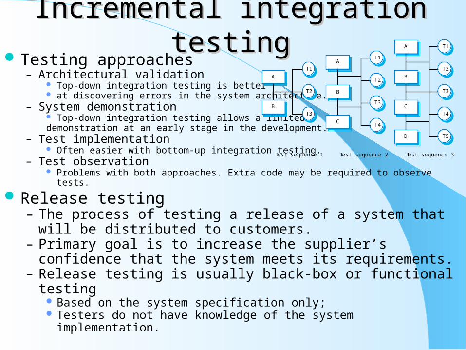
Incremental integration testingIncremental integration testing Testing approaches
– Architectural validation Top-down integration testing is better at discovering errors in the system architecture.
– System demonstration Top-down integration testing allows a limited demonstration at an early stage in the development.
– Test implementation Often easier with bottom-up integration testing.
– Test observation Problems with both approaches. Extra code may be required to observe tests.
Release testing– The process of testing a release of a system that will be distributed
to customers.– Primary goal is to increase the supplier’s confidence that the
system meets its requirements.– Release testing is usually black-box or functional testing
Based on the system specification only; Testers do not have knowledge of the system implementation.
T3
T2
T1
T4
T5
A
B
C
D
T2
T1
T3
T4
A
B
C
T1
T2
T3
A
B
Test sequence 1 Test sequence 2 Test sequence 3

Testing guidelinesTesting guidelines– Testing guidelines are hints for the testing team to help them
choose tests that will reveal defects in the system Choose inputs that force the system to generate all error messages; Design inputs that cause buffers to overflow; Repeat the same input or input series several times; Force invalid outputs to be generated; Force computation results to be too large or too small.
Use cases– Use cases can be a basis for deriving the tests for a system. They
help identify operations to be tested and help design the required test cases.
– From an associated sequence diagram, the inputs and outputs to be created for the tests can be identified.

Performance testingPerformance testing– Part of release testing may involve testing the emergent properties
of a system, such as performance and reliability.– Performance tests usually involve planning a series of tests where
the load is steadily increased until the system performance becomes unacceptable.
Stress testing– Exercises the system beyond its maximum design load. Stressing
the system often causes defects to come to light.
– Stressing the system test failure behaviour.. Systems should not fail catastrophically. Stress testing checks for unacceptable loss of service or data.
– Stress testing is particularly relevant to distributed systems that can exhibit severe degradation as a network becomes overloaded. 106
Component testingComponent testing– Component or unit testing is the process of testing individual
components in isolation.– It is a defect testing process.– Components may be:
Individual functions or methods within an object; Object classes with several attributes and methods; Composite components with defined interfaces used to access their
functionality. Object class testing
– Complete test coverage of a class involves Testing all operations associated with an object; Setting and interrogating all object attributes; Exercising the object in all possible states.
– Inheritance makes it more difficult to design object class tests as the information to be tested is not localised.
Interface testingInterface testing– Objectives are to detect faults due to interface errors or invalid assumptions
about interfaces.– Particularly important for object-oriented development as objects are defined by
their interfaces. Interface types
– Parameter interfaces: Data passed from one procedure to another.
– Shared memory interfaces: Block of memory is shared between procedures or functions.
– Procedural interfaces: Sub-system encapsulates a set of procedures to be called by other sub-systems.
– Message passing interfaces: Sub-systems request services from other sub-systems
Interface errors– Interface misuse
A calling component calls another component and makes an error in its use of its interface e.g. parameters in the wrong order.
– Interface misunderstanding A calling component embeds assumptions about the behaviour of the called component which
are incorrect.– Timing errors
The called and the calling component operate at different speeds and out-of-date information is accessed.
Interface testing guidelinesInterface testing guidelines– Design tests so that parameters to a called procedure are at the
extreme ends of their ranges.– Always test pointer parameters with null pointers.– Design tests which cause the component to fail.– Use stress testing in message passing systems.– In shared memory systems, vary the order in which components
are activated. Test case design
– Involves designing the test cases (inputs and outputs) used to test the system.
– The goal of test case design is to create a set of tests that are effective in validation and defect testing.
– Design approaches: Requirements-based testing; Partition testing; Structural testing.

Requirements based testingRequirements based testing– A general principle of requirements engineering is that
requirements should be testable.
– Requirements-based testing is a validation testing technique where you consider each requirement and derive a set of tests for that requirement.
Partition testing– Input data and output results often fall into different classes where
all members of a class are related.
– Each of these classes is an equivalence partition or domain where the program behaves in an equivalent way for each class member.
– Test cases should be chosen from each partition.

Structural testingStructural testing– Sometime called white-box testing.
– Derivation of test cases according to program structure. Knowledge of the program is used to identify additional test cases.
– Objective is to exercise all program statements (not all path combinations).
Path testing– The objective of path testing is to ensure that the set of test cases is
such that each path through the program is executed at least once.– The starting point for path testing is a program flow graph that
shows nodes representing program decisions and arcs representing the flow of control.
– Statements with conditions are therefore nodes in the flow graph.
Test automationTest automation– Testing is an expensive process phase. Testing workbenches
provide a range of tools to reduce the time required and total testing costs.
– Systems such as Junit support the automatic execution of tests.
– Most testing workbenches are open systems because testing needs are organisation-specific.
– They are sometimes difficult to integrate with closed design and analysis workbenches.
Testing workbench adaptation– Scripts may be developed for user interface simulators and
patterns for test data generators.
– Test outputs may have to be prepared manually for comparison.
– Special-purpose file comparators may be developed.

Key points– Testing can show the presence of faults in a system; it cannot
prove there are no remaining faults.– Component developers are responsible for component testing;
system testing is the responsibility of a separate team.– Integration testing is testing increments of the system; release
testing involves testing a system to be released to a customer.– Use experience and guidelines to design test cases in defect
testing.– Interface testing is designed to discover defects in the interfaces of
composite components.– Equivalence partitioning is a way of discovering test cases - all
cases in a partition should behave in the same way.– Structural analysis relies on analysing a program and deriving tests
from this analysis.– Test automation reduces testing costs by supporting the test
process with a range of software tools.