Software engineering jwfiles 3
109
Einstein College of Engineering CS51 SOFTWARE ENGINEERING UNIT I SOFTWARE PRODUCT AND PROCESS Software engineering paradigm: • The framework activities will always be applied on every project ... BUT the tasks (and degree of rigor) for each activity will vary based on: – the type of project – characteristics of the project – common sense judgment; concurrence of the project team The software process: • A structured set of activities required to develop a software system – Specification; – Design; – Validation; – Evolution. • A software process model is an abstract representation of a process. It presents a description of a process from some particular perspective. Waterfall model/Linear Sequential Model/classic life cycle : • Systems Engineering – Software as part of larger system, determine requirements for all system elements, allocate requirements to software. • Software Requirements Analysis – Develop understanding of problem domain, user needs, function, performance, interfaces, ... – Software Design – Multi-step process to determine architecture, interfaces, data structures, functional detail. Produces (high-level) form that can be checked for quality, conformance before coding. • Coding – Produce machine readable and executable form, match HW, OS and design needs. • Testing www.jntuworld.com www.jntuworld.com www.jwjobs.net
-
Upload
azhar-shaik -
Category
Education
-
view
313 -
download
1
Transcript of Software engineering jwfiles 3
Einstein College of Engineering
CS51 SOFTWARE ENGINEERING
UNIT I
SOFTWARE PRODUCT AND PROCESS
Software engineering paradigm:
• The framework activities will always be applied on every project ... BUT the tasks (and
degree of rigor) for each activity will vary based on:
– the type of project
– characteristics of the project
– common sense judgment; concurrence of the project team
The software process:
• A structured set of activities required to develop a software system
– Specification;
– Design;
– Validation;
– Evolution.
• A software process model is an abstract representation of a process. It presents a
description of a process from some particular perspective.
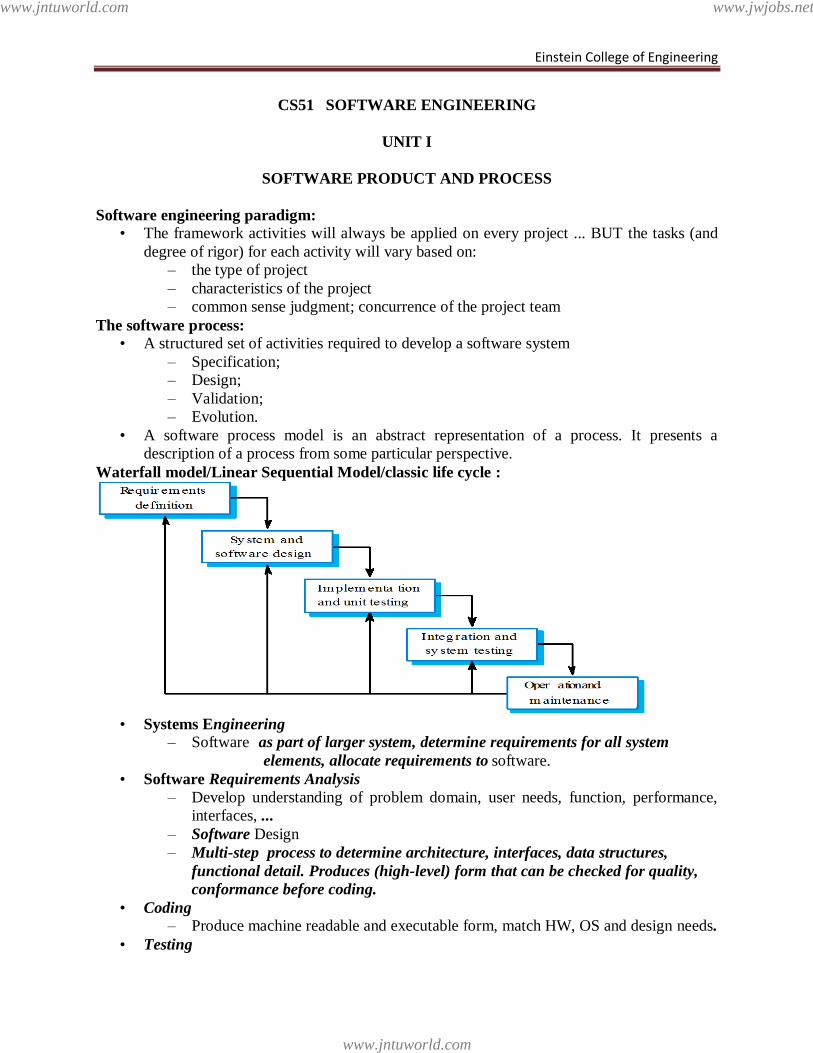
Waterfall model/Linear Sequential Model/classic life cycle :
• Systems Engineering
– Software as part of larger system, determine requirements for all system
elements, allocate requirements to software.
• Software Requirements Analysis
– Develop understanding of problem domain, user needs, function, performance,
interfaces, ...
– Software Design
– Multi-step process to determine architecture, interfaces, data structures,
functional detail. Produces (high-level) form that can be checked for quality,
conformance before coding.
• Coding – Produce machine readable and executable form, match HW, OS and design needs.
• Testing
www.jntuworld.com
www.jntuworld.com
www.jwjobs.net
Einstein College of Engineering
– Confirm that components, subsystems and complete products meet requirements,
specifications and quality, find and fix defects.
• Maintenance – Incrementally, evolve software to fix defects, add features, adapt to new
condition. Often 80% of effort spent here!
Waterfall model phases:
• Requirements analysis and definition
• System and software design
• Implementation and unit testing
• Integration and system testing
• Operation and maintenance
• The main drawback of the waterfall model is the difficulty of accommodating change
after the process is underway. One phase has to be complete before moving onto the next
phase.
• Each phase terminates only when the documents are complete and approved by the SQA
group.
• Maintenance begins when the client reports an error after having accepted the product. It
could also begin due to a change in requirements after the client has accepted the product
Waterfall model: Advantages:
• Disciplined approach
• Careful checking by the Software Quality Assurance Group at the end of each phase.
• Testing in each phase.
• Documentation available at the end of each phase.
Waterfall model problems:
• It is difficult to respond to changing customer requirements.
• Therefore, this model is only appropriate when the requirements are well-understood and
changes will be fairly limited during the design process.
• Few business systems have stable requirements.
• The waterfall model is mostly used for large systems engineering projects where a system
is developed at several sites.
• The customer must have patience. A working version of the program will not be available
until late in the project time-span
• Feedback from one phase to another might be too late and hence expensive.
The Prototyping Models:
• Often, a customer defines a set of general objectives for software but does not identify
detailed input, processing, or output requirements.
• In other cases, the developer may be unsure of the efficiency of an algorithm, the
adaptability of an operating system, or the form that human –machine interaction should
take
• In this case prototyping paradigm may offer the best approach
• Requirements gathering
• Quick design
• Prototype building
• Prototype evaluation by customers
• Prototype may be refined
www.jntuworld.com
www.jntuworld.com
www.jwjobs.net
Einstein College of Engineering
• Prototype thrown away and software developed using formal process{ it is used to define
the requirement} Prototyping
Strengths:
• Requirements can be set earlier and more reliably
• Customer sees results very quickly.
• Customer is educated in what is possible helping to refine requirements.
• Requirements can be communicated more clearly and completely
• Between developers and clients Requirements and design options can be
investigated quickly and Cheaply
Weaknesses:
– Requires a rapid prototyping tool and expertise in using it–a cost for the
development organisation
– Smoke and mirrors - looks like a working version, but it is not.
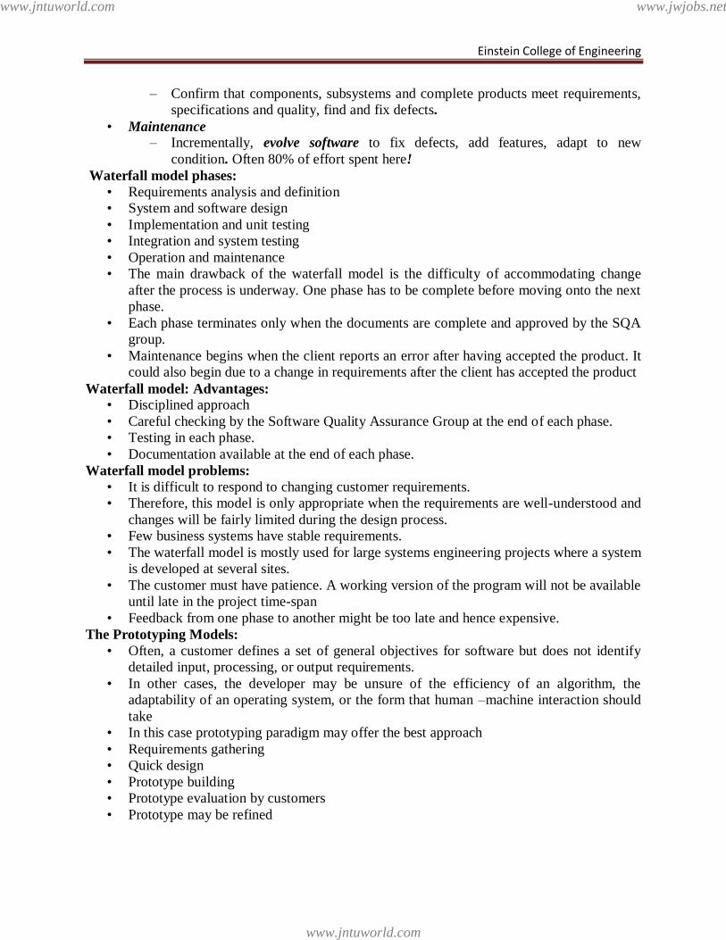
The RAD Model:
• Rapid Application Development is a linear sequential software development process
model that emphasizes an extremely short development cycle
• Rapid application achieved by using a component based construction approach
• If requirements are well understood and project scope is constrained the RAD process
enables a development team to create a ―fully functional system‖
RAD phases :
• Business modeling
• Data modeling
• Process modeling
Communicat ion
Planning
Mode lingbusiness modeling
dat a modeling
process modeling
Const ruct ioncomponent reuse
aut omat ic code
generat ion
t est ing
De ployme nt
6 0 - 9 0 days
Team # 1
Modelingbusiness m odel ing
dat a m odel ing
process m odel ing
Const ruct ioncom ponent reuse
aut om at ic code
generat ion
t est ing
M o d e lin gbusiness m odeling
data m odeling
process m odeling
Co n st ru ct io ncom ponent reuse
autom at ic code
generat ion
test ing
Team # 2
Team # n
int egrat ion
delivery
feedback
www.jntuworld.com
www.jntuworld.com
www.jwjobs.net
Einstein College of Engineering
• Application generation
• Testing and turnover
Business modeling:
• What information drives the business process?
• What information is generated?
• Who generates it?
Data Modeling:
• The information flow defined as part of the business modeling phase is refined into a set
of data objects that are needed to support the business.
• The characteristics ( called attributes) of each object are identified and the relationships
between these objects are defined
Process modeling:
• The data modeling phase are transformed to achieve the information flow necessary to
implement a business function.
• Processing descriptions are created for adding , modifying, deleting, or retrieving a data
object
Application generation:
• RAD assumes the use of 4 generation techniques.
• Rather than creating software using conventional 3 generation programming languages,
the RAD process works to reuse existing program components (when possible) or created
reusable components (when necessary)
Testing and Turnover:
• Since the RAD process emphasizes reuse, many of the program components have already
been testing.
• This reduces over all testing time.
• However, new components must be tested and all interfaces must be fully exercised
Advantages &Disadvantages of RAD:
Advantages
• Extremely short development time.
• Uses component-based construction and emphasises reuse and code generation
Disadvantages
• Large human resource requirements (to create all of the teams).
• Requires strong commitment between developers and customers for “rapid-fire”
activities.
• High performance requirements maybe can’t be met (requires tuning the components).
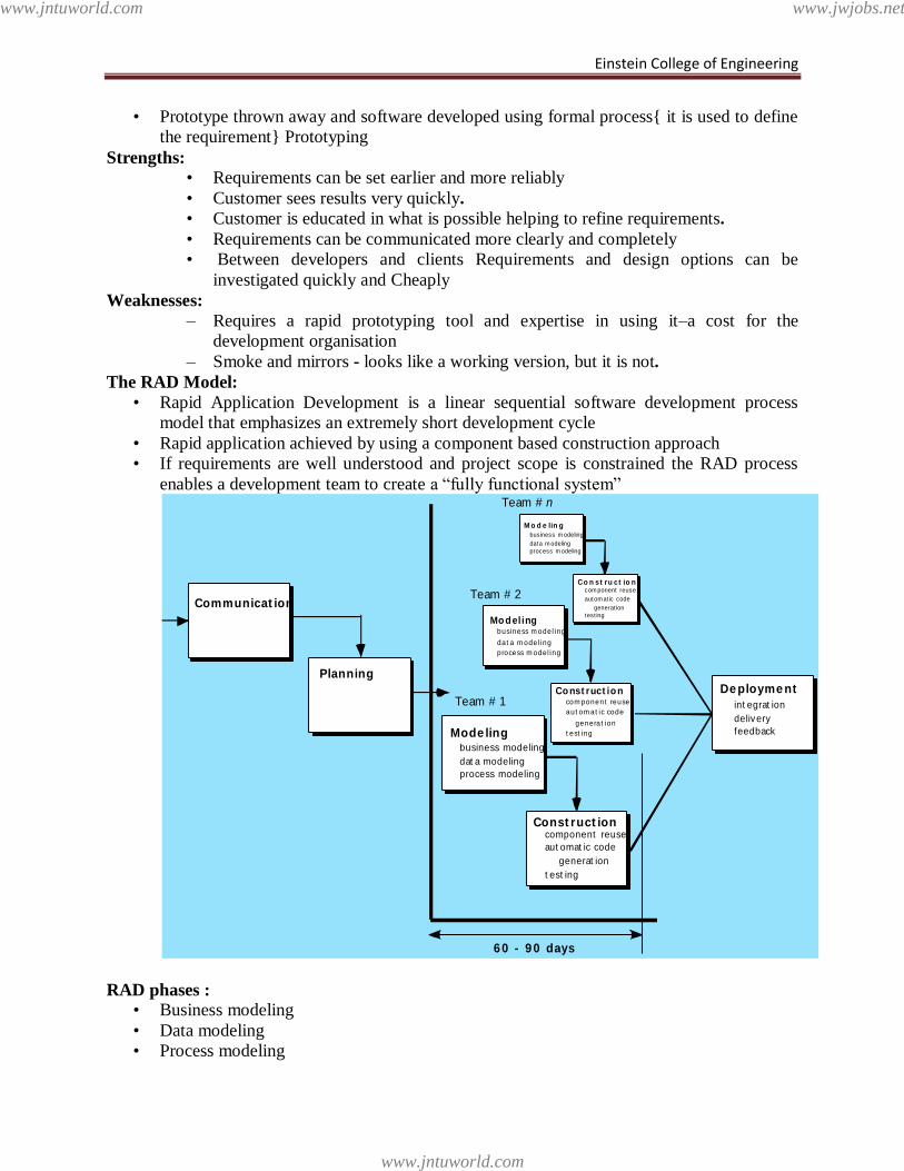
The Incremental Model
:
C o m m u n i c a t i o n
P l a n n i n g
M o d e l i n g
C o n s t r u c t i o n
D e p l o y m e n t
d e l i v e r y
f e e d b a c k
analy s is
des ign c ode
t es t
increment # 1
increment # 2
delivery of
1st increment
delivery of
2nd increment
delivery of
nt h increment
increment # n
project calendar t ime
C o m m u n i c a t i o n
P l a n n i n g
M o d e l i n g
C o n s t r u c t i o n
D e p l o y m e n t
d e l i v e r y
f e e d b a c k
analy s is
des ign c ode
t es t
C o m m u n i c a t i o n
P l a n n i n g
M o d e l i n g
C o n s t r u c t i o n
D e p l o y m e n t
d e l i v e r y
f e e d b a c k
analy s is
des ignc ode
t es t
www.jntuworld.com
www.jntuworld.com
www.jwjobs.net
Einstein College of Engineering
The Incremental development
• Combination of linear + prototype
• Rather than deliver the system as a single delivery, the development and delivery is
broken down into increments with each increment delivering part of the required
functionality
• User requirements are prioritised and the highest priority requirements are included in
early increments
• Once the development of an increment is started, the requirements are frozen though
requirements for later increments can continue to evolve
Incremental development advantages:
• The customer is able to do some useful work after release
• Lower risk of overall project failure
• The highest priority system services tend to receive the most testing
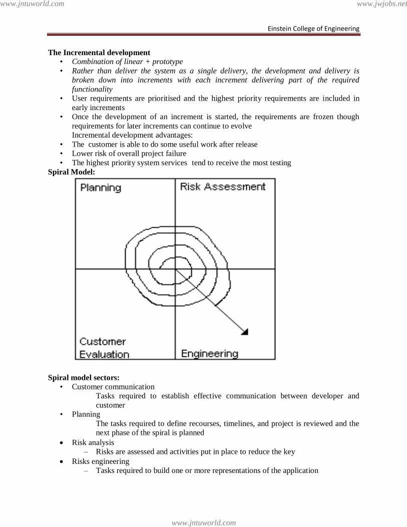
Spiral Model:
Spiral model sectors:
• Customer communication
Tasks required to establish effective communication between developer and
customer
• Planning
The tasks required to define recourses, timelines, and project is reviewed and the
next phase of the spiral is planned
Risk analysis
– Risks are assessed and activities put in place to reduce the key
Risks engineering
– Tasks required to build one or more representations of the application
www.jntuworld.com
www.jntuworld.com
www.jwjobs.net
Einstein College of Engineering
• Construction & release
– Tasks required to construct, test, install and provide user support (e.g
documentation and training)
• Customer evaluation
– Customer feedback collected every stage
Spiral Model Advantages:
• Focuses attention on reuse options.
• Focuses attention on early error elimination.
• Puts quality objectives up front.
• Integrates development and maintenance.
• Provides a framework for hardware/software Development.
System Engineering
Software engineering occurs as a consequence of a process called system engineering.
Instead of concentrating solely on software, system engineering focuses on a variety of
elements, analyzing, designing, and organizing those elements into a system that can be a
product, a service, or a technology for the transformation of information or control.
www.jntuworld.com
www.jntuworld.com
www.jwjobs.net
Einstein College of Engineering
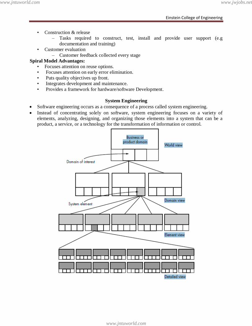
The system engineering process usually begins with a ―world view.‖ That is, the entire
business or product domain is examined to ensure that the proper business or technology
context can be established.
The world view is refined to focus more fully on specific domain of interest. Within a
specific domain, the need for targeted system elements (e.g., data, software, hardware,
people) is analyzed. Finally, the analysis, design, and construction of a targeted system
element is initiated.
At the top of the hierarchy, a very broad context is established and, at the bottom, detailed
technical activities, performed by the relevant engineering discipline (e.g., hardware or
software engineering), are conducted.
Stated in a slightly more formal manner, the world view (WV) is composed of a set of
domains (Di), which can each be a system or system of systems in its own right.
WV = {D1, D2, D3, . . . , Dn}
Each domain is composed of specific elements (Ej) each of which serves some role in
accomplishing the objective and goals of the domain or component:
Di = {E1, E2, E3, . . . , Em}
Finally, each element is implemented by specifying the technical components (Ck) that
achieve the necessary function for an element:
Ej = {C1, C2, C3, . . . , Ck}
Computer Based System
computer-based system as A set or arrangement of elements that are organized to accomplish
some predefined goal by processing information.
The goal may be to support some business function or to develop a product that can be sold
to generate business revenue.
To accomplish the goal, a computer-based system makes use of a variety of system elements:
1. Software. Computer programs, data structures, and related documentation that serve to
effect the logical method, procedure, or control that is required.
2. Hardware. Electronic devices that provide computing capability, the interconnectivity
devices (e.g., network switches, telecommunications devices) that enable the flow of
data, and electromechanical devices (e.g., sensors, motors, pumps) that provide external
world function.
3. People. Users and operators of hardware and software.
4. Database. A large, organized collection of information that is accessed via software.
5. Documentation. Descriptive information (e.g., hardcopy manuals, on-line help files,
Web sites) that portrays the use and/or operation of the system.
6. Procedures. The steps that define the specific use of each system element or the
procedural context in which the system resides.
The elements combine in a variety of ways to transform information. For example, a
marketing department transforms raw sales data into a profile of the typical purchaser of a
product; a robot transforms a command file containing specific instructions into a set of
control signals that cause some specific physical action.
Creating an information system to assist the marketing department and control software to
support the robot both require system engineering.
www.jntuworld.com
www.jntuworld.com
www.jwjobs.net
Einstein College of Engineering
One complicating characteristic of computer-based systems is that the elements constituting
one system may also represent one macro element of a still larger system. The macro element
is a computer-based system that is one part of a larger computer-based system.
As an example, we consider a "factory automation system" that is essentially a hierarchy of
systems. At the lowest level of the hierarchy we have a numerical control machine, robots,
and data entry devices.
Each is a computerbased system in its own right. The elements of the numerical control
machine include electronic and electromechanical hardware (e.g., processor and memory,
motors, sensors), software (for communications, machine control, interpolation), people (the
machine operator), a database (the stored NC program), documentation, and procedures.
A similar decomposition could be applied to the robot and data entry device. Each is a
computer-based system.
At the next level in the hierarchy, a manufacturing cell is defined. The manufacturing cell is a
computer-based system that may have elements of its own (e.g., computers, mechanical
fixtures) and also integrates the macro elements that we have called numerical control
machine, robot, and data entry device.
Business Process Engineering Overview
The goal of business process engineering (BPE) is to define architectures that will enable a
business to use information effectively.
When taking a world view of a company‘s information technology needs, there is little doubt
that system engineering is required. Not only is the specification of the appropriate
computing architecture required, but the software architecture that populates the ―unique
configuration of heterogeneous computing resources‖ must be developed.
Business process engineering is one approach for creating an overall plan for implementing
the computing architecture .
Three different architectures must be analyzed and designed within the context of business
objectives and goals:
• data architecture
• applications architecture
• technology infrastructure
The data architecture provides a framework for the information needs of a business or
business function. The individual building blocks of the architecture are the data objects that
are used by the business. A data object contains a set of attributes that define some aspect,
quality, characteristic, or descriptor of the data that are being described.
The application architecture encompasses those elements of a system that transform objects
within the data architecture for some business purpose. In the context of this book, we
consider the application architecture to be the system of programs (software) that performs
this transformation. However, in a broader context, the application architecture might
incorporate the role of people (who are information transformers and users) and business
procedures that have not been automated.
The technology infrastructure provides the foundation for the data and application
architectures. The infrastructure encompasses the hardware and software that are used to
support the application and data. This includes computers, operating systems, networks,
telecommunication links, storage technologies, and the architecture (e.g., client/server) that
has been designed to implement these technologies.
www.jntuworld.com
www.jntuworld.com
www.jwjobs.net
Einstein College of Engineering
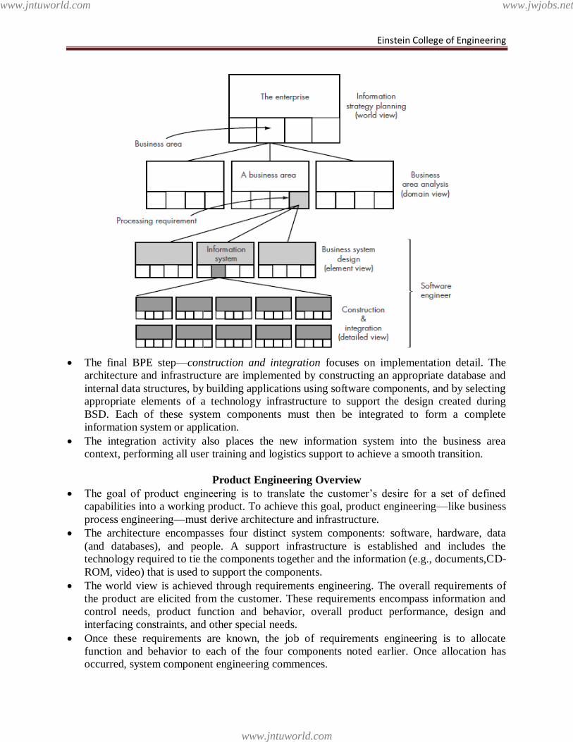
The final BPE step—construction and integration focuses on implementation detail. The
architecture and infrastructure are implemented by constructing an appropriate database and
internal data structures, by building applications using software components, and by selecting
appropriate elements of a technology infrastructure to support the design created during
BSD. Each of these system components must then be integrated to form a complete
information system or application.
The integration activity also places the new information system into the business area
context, performing all user training and logistics support to achieve a smooth transition.
Product Engineering Overview
The goal of product engineering is to translate the customer‘s desire for a set of defined
capabilities into a working product. To achieve this goal, product engineering—like business
process engineering—must derive architecture and infrastructure.
The architecture encompasses four distinct system components: software, hardware, data
(and databases), and people. A support infrastructure is established and includes the
technology required to tie the components together and the information (e.g., documents,CD-
ROM, video) that is used to support the components.
The world view is achieved through requirements engineering. The overall requirements of
the product are elicited from the customer. These requirements encompass information and
control needs, product function and behavior, overall product performance, design and
interfacing constraints, and other special needs.
Once these requirements are known, the job of requirements engineering is to allocate
function and behavior to each of the four components noted earlier. Once allocation has
occurred, system component engineering commences.
www.jntuworld.com
www.jntuworld.com
www.jwjobs.net
Einstein College of Engineering
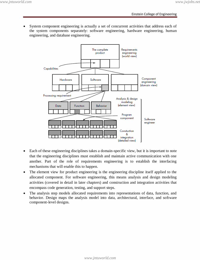
System component engineering is actually a set of concurrent activities that address each of
the system components separately: software engineering, hardware engineering, human
engineering, and database engineering.
Each of these engineering disciplines takes a domain-specific view, but it is important to note
that the engineering disciplines must establish and maintain active communication with one
another. Part of the role of requirements engineering is to establish the interfacing
mechanisms that will enable this to happen.
The element view for product engineering is the engineering discipline itself applied to the
allocated component. For software engineering, this means analysis and design modeling
activities (covered in detail in later chapters) and construction and integration activities that
encompass code generation, testing, and support steps.
The analysis step models allocated requirements into representations of data, function, and
behavior. Design maps the analysis model into data, architectural, interface, and software
component-level designs.
www.jntuworld.com
www.jntuworld.com
www.jwjobs.net
Einstein College of Engineering
UNIT II
SOFTWARE REQUIREMENTS
The process of establishing the services that the customer requires from a system and the
constraints under which it operates and is developed
Requirements may be functional or non-functional
• Functional requirements describe system services or functions
• Non-functional requirements is a constraint on the system or on the development
process
Types of requirements
User requirements
• Statements in natural language (NL) plus diagrams of the services the system
provides and its operational constraints. Written for customers
System requirements
• A structured document setting out detailed descriptions of the system services.
Written as a contract between client and contractor
Software specification
• A detailed software description which can serve as a basis for a design or
implementation. Written for developers
Functional and Non-Functional
Functional requirements
Functionality or services that the system is expected to provide.
Functional requirements may also explicitly state what the system shouldn‘t do.
Functional requirements specification should be:
• Complete: All services required by the user should be defined
• Consistent: should not have contradictory definition (also avoid ambiguity
don‘t leave room for different interpretations)
Examples of functional requirements
The LIBSYS system
A library system that provides a single interface to a number of databases of articles in
different libraries.
Users can search for, download and print these articles for personal study.
The user shall be able to search either all of the initial set of databases or select a subset from
it.
The system shall provide appropriate viewers for the user to read documents in the document
store.
Every order shall be allocated a unique identifier (ORDER_ID) which the user shall be able
to copy to the account‘s permanent storage area.
Non-Functional requirements
www.jntuworld.com
www.jntuworld.com
www.jwjobs.net
Einstein College of Engineering
Requirements that are not directly concerned with the specific functions delivered by the
system
Typically relate to the system as a whole rather than the individual system features
Often could be deciding factor on the survival of the system (e.g. reliability, cost, response
time)
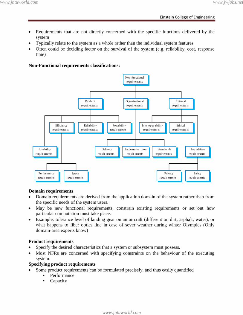
Non-Functional requirements classifications:
Domain requirements
Domain requirements are derived from the application domain of the system rather than from
the specific needs of the system users.
May be new functional requirements, constrain existing requirements or set out how
particular computation must take place.
Example: tolerance level of landing gear on an aircraft (different on dirt, asphalt, water), or
what happens to fiber optics line in case of sever weather during winter Olympics (Only
domain-area experts know)
Product requirements
Specify the desired characteristics that a system or subsystem must possess.
Most NFRs are concerned with specifying constraints on the behaviour of the executing
system.
Specifying product requirements
Some product requirements can be formulated precisely, and thus easily quantified
• Performance
• Capacity
Performance
requir ements
Space
requir ements
Usa bility
requir ements
Efficiency
requir ements
Relia bility
requir ements
Porta bility
requir ements
Inter oper a bility
requir ements
Ethical
requir ements
Leg islative
requir ements
Implementa tion
requir ements
Standar ds
requir ements
Deli very
requir ements
Safety
requir ements
Pri vacy
requir ements
Product
requir ements
Organisational
requir ements
External
requir ements
Non-functional
requir ements
www.jntuworld.com
www.jntuworld.com
www.jwjobs.net
Einstein College of Engineering
Others are more difficult to quantify and, consequently, are often stated informally
• Usability
Process requirements
Process requirements are constraints placed upon the development process of the system
Process requirements include:
• Requirements on development standards and methods which must be followed
• CASE tools which should be used
• The management reports which must be provided
Examples of process requirements
The development process to be used must be explicitly defined and must be conformant with
ISO 9000 standards
The system must be developed using the XYZ suite of CASE tools
Management reports setting out the effort expended on each identified system component
must be produced every two weeks
A disaster recovery plan for the system development must be specified
External requirements
May be placed on both the product and the process
Derived from the environment in which the system is developed
External requirements are based on:
• application domain information
• organisational considerations
• the need for the system to work with other systems
• health and safety or data protection regulations
• or even basic natural laws such as the laws of physics
Examples of external requirements
Medical data system The organisation‘s data protection officer must certify that all data is
maintained according to data protection legislation before the system is put into operation.
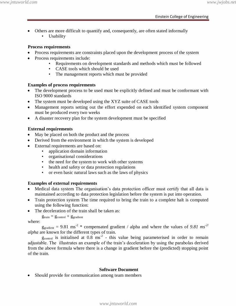
Train protection system The time required to bring the train to a complete halt is computed
using the following function:
The deceleration of the train shall be taken as:
gtrain = gcontrol + ggradient
where:
ggradient = 9.81 ms-2
* compensated gradient / alpha and where the values of 9.81 ms-2/
alpha are known for the different types of train.
gcontrol is initialised at 0.8 ms-2
- this value being parameterised in order to remain
adjustable. The illustrates an example of the train‘s deceleration by using the parabolas derived
from the above formula where there is a change in gradient before the (predicted) stopping point
of the train.
Software Document
Should provide for communication among team members
www.jntuworld.com
www.jntuworld.com
www.jwjobs.net
Einstein College of Engineering
Should act as an information repository to be used by maintenance engineers
Should provide enough information to management to allow them to perform all program
management related activities
Should describe to users how to operate and administer the system
Specify external system behaviour
Specify implementation constraints
Easy to change
Serve as reference tool for maintenance
Record forethought about the life cycle of the system i.e. predict changes
Characterise responses to unexpected events
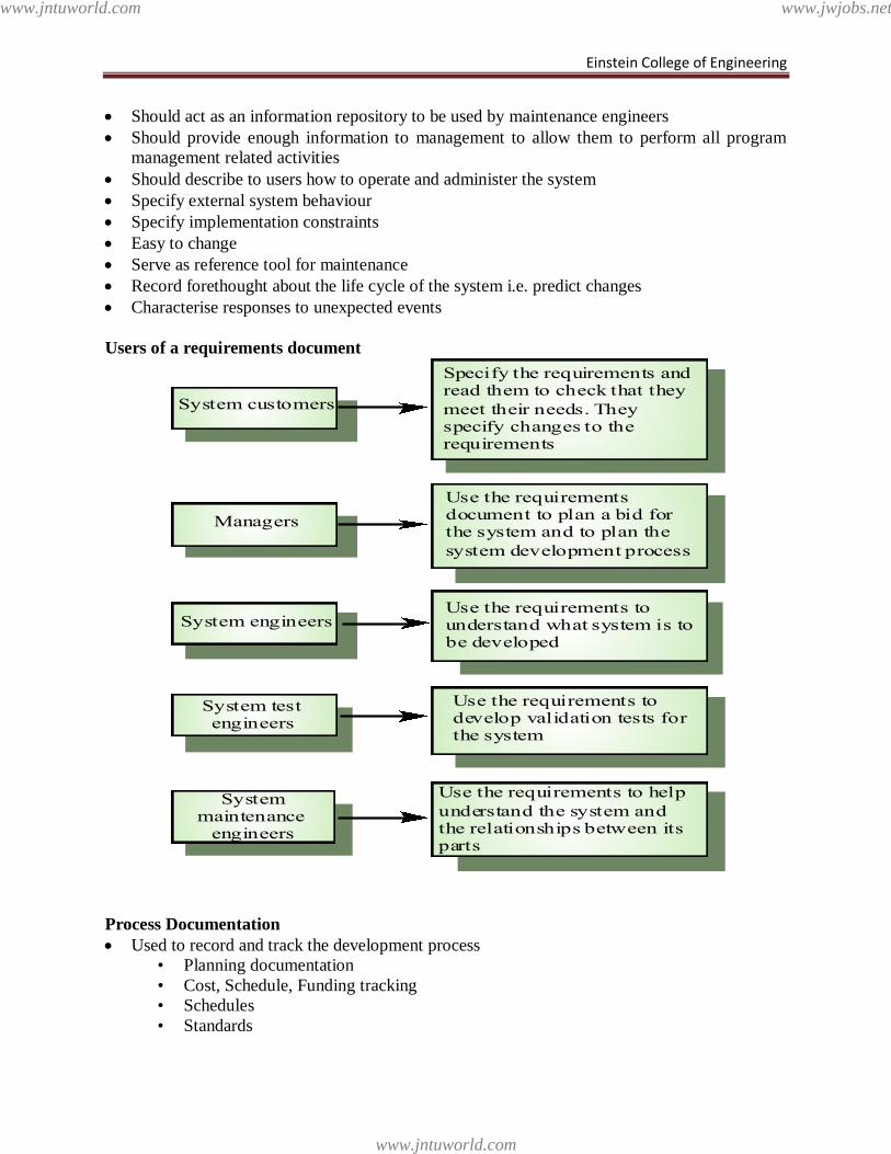
Users of a requirements document
Process Documentation
Used to record and track the development process
• Planning documentation
• Cost, Schedule, Funding tracking
• Schedules
• Standards
Use the requirements todevelop validation tests forthe system
Use the requirementsdocument to plan a bid forthe system and to plan the
system development process
Use the requirements tounderstand what system is tobe developed
System testengineers
Managers
System engineers
Specify the requirements andread them to check that they
meet their needs. Theyspecify changes to therequirements
System customers
Use the requirements to help
understand the system andthe relationships between itsparts
Systemmaintenance
engineers
www.jntuworld.com
www.jntuworld.com
www.jwjobs.net
Einstein College of Engineering
This documentation is created to allow for successful management of a software product
Has a relatively short lifespan
• Only important to internal development process
• Except in cases where the customer requires a view into this data
Some items, such as papers that describe design decisions should be extracted and moved
into the product documentation category when they become implemented
• Product Documentation
Describes the delivered product
Must evolve with the development of the software product
Two main categories:
• System Documentation
• User Documentation
Product Documentation
System Documentation
• Describes how the system works, but not how to operate it
Examples:
• Requirements Spec
• Architectural Design
• Detailed Design
• Commented Source Code
Including output such as JavaDoc
• Test Plans
Including test cases
• V&V plan and results
• List of Known Bugs
User Documentation has two main types
• End User
• System Administrator
In some cases these are the same people
• The target audience must be well understood!
There are five important areas that should be documented for a formal release of a software
application
• These do not necessarily each have to have their own document, but the topics should
be covered thoroughly
Functional Description of the Software
Installation Instructions
Introductory Manual
Reference Manual
System Administrator‘s Guide
Document Quality
Providing thorough and professional documentation is important for any size product
development team
www.jntuworld.com
www.jntuworld.com
www.jwjobs.net
Einstein College of Engineering
• The problem is that many software professionals lack the writing skills to create
professional level documents
Document Structure
All documents for a given product should have a similar structure
• A good reason for product standards
The IEEE Standard for User Documentation lists such a structure
• It is a superset of what most documents need
The authors ―best practices‖ are:
Put a cover page on all documents
Divide documents into chapters with sections and subsections
Add an index if there is lots of reference information
Add a glossary to define ambiguous terms
Standards
Standards play an important role in the development, maintenance and usefulness of
documentation
Standards can act as a basis for quality documentation
• But are not good enough on their own
Usually define high level content and organization
There are three types of documentation standards
1.Process Standards
Define the approach that is to be used when creating the documentation
Don‘t actually define any of the content of the documents
2. Product Standards
Goal is to have all documents created for a specific product attain a consistent structure and
appearance
• Can be based on organizational or contractually required standards
Four main types:
• Documentation Identification Standards
• Document Structure Standards
• Document Presentation Standards
• Document Update Standards
One caveat:
• Documentation that will be viewed by end users should be created in a way that is
best consumed and is most attractive to them
• Internal development documentation generally does not meet this need
3. Interchange Standards
Deals with the creation of documents in a format that allows others to effectively use
• PDF may be good for end users who don‘t need to edit
• Word may be good for text editing
www.jntuworld.com
www.jntuworld.com
www.jwjobs.net
Einstein College of Engineering
• Specialized CASE tools need to be considered
This is usually not a problem within a single organization, but when sharing data between
organizations it can occur
• This same problem is faced all the time during software integration
Other Standards
IEEE
• Has a published standard for user documentation
• Provides a structure and superset of content areas
• Many organizations probably won‘t create documents that completely match the
standard
Writing Style
• Ten ―best practices‖ when writing are provided
• Author proposes that group edits of important documents should occur in a similar
fashion to software walkthroughs
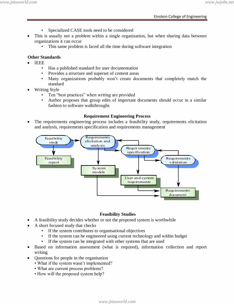
Requirement Engineering Process
The requirements engineering process includes a feasibility study, requirements elicitation
and analysis, requirements specification and requirements management
Feasibility Studies
A feasibility study decides whether or not the proposed system is worthwhile
A short focused study that checks
• If the system contributes to organisational objectives
• If the system can be engineered using current technology and within budget
• If the system can be integrated with other systems that are used
Based on information assessment (what is required), information collection and report
writing
Questions for people in the organisation
• What if the system wasn‘t implemented?
• What are current process problems?
• How will the proposed system help?
Feasibilitystudy
Requirementselicitation and
analysisRequirementsspecification
Requirementsvalidation
Feasibilityreport
Systemmodels
User and systemrequirements
Requirements
document
www.jntuworld.com
www.jntuworld.com
www.jwjobs.net
Einstein College of Engineering
• What will be the integration problems?
• Is new technology needed? What skills?
• What facilities must be supported by the proposed system?
Elicitation and analysis
Sometimes called requirements elicitation or requirements discovery
Involves technical staff working with customers to find out about
• the application domain
• the services that the system should provide
• the system‘s operational constraints
May involve end-users, managers, engineers involved in maintenance, domain experts, trade
unions, etc.
• These are called stakeholders
Problems of requirements analysis
Stakeholders don‘t know what they really want
Stakeholders express requirements in their own terms
Different stakeholders may have conflicting requirements
Organisational and political factors may influence the system requirements
The requirements change during the analysis process
• New stakeholders may emerge and the business environment change
System models
Different models may be produced during the requirements analysis activity
Requirements analysis may involve three structuring activities which result in these different
models
• Partitioning – Identifies the structural (part-of) relationships between entities
• Abstraction – Identifies generalities among entities
• Projection – Identifies different ways of looking at a problem
System models will be covered on January 30
Scenarios
Scenarios are descriptions of how a system is used in practice
They are helpful in requirements elicitation as people can relate to these more readily than
abstract statement of what they require from a system
Scenarios are particularly useful for adding detail to an outline requirements description
Ethnography
A social scientists spends a considerable time observing and analysing how people actually
work
People do not have to explain or articulate their work
Social and organisational factors of importance may be observed
Ethnographic studies have shown that work is usually richer and more complex than
suggested by simple system models
www.jntuworld.com
www.jntuworld.com
www.jwjobs.net
Einstein College of Engineering
Requirements validation
Concerned with demonstrating that the requirements define the system that the customer
really wants
Requirements error costs are high so validation is very important
• Fixing a requirements error after delivery may cost up to 100 times the cost of fixing
an implementation error
Requirements checking
• Validity
• Consistency
• Completeness
• Realism
• Verifiability
Requirements validation techniques
Reviews
• Systematic manual analysis of the requirements
Prototyping
• Using an executable model of the system to check requirements.
Test-case generation
• Developing tests for requirements to check testability
Automated consistency analysis
• Checking the consistency of a structured requirements description
Requirements management
Requirements management is the process of managing changing requirements during the
requirements engineering process and system development
Requirements are inevitably incomplete and inconsistent
• New requirements emerge during the process as business needs change and a better
understanding of the system is developed
• Different viewpoints have different requirements and these are often contradictory
Software prototyping Incomplete versions of the software program being developed. Prototyping can also be
used by end users to describe and prove requirements that developers have not considered
Benefits:
The software designer and implementer can obtain feedback from the users early in the
project. The client and the contractor can compare if the software made matches the software
specification, according to which the software program is built.
It also allows the software engineer some insight into the accuracy of initial project
estimates and whether the deadlines and milestones proposed can be successfully met.
Process of prototyping
1. Identify basic requirements
Determine basic requirements including the input and output information desired. Details,
such as security, can typically be ignored.
www.jntuworld.com
www.jntuworld.com
www.jwjobs.net
Einstein College of Engineering
2. Develop Initial Prototype
The initial prototype is developed that includes only user interfaces. (See Horizontal
Prototype, below)
3. Review
The customers, including end-users, examine the prototype and provide feedback on
additions or changes.
4. Revise and Enhance the Prototype
Using the feedback both the specifications and the prototype can be improved. Negotiation
about what is within the scope of the contract/product may be necessary. If changes are
introduced then a repeat of steps #3 and #4 may be needed.
Dimensions of prototypes
1. Horizontal Prototype
It provides a broad view of an entire system or subsystem, focusing on user interaction more
than low-level system functionality, such as database access. Horizontal prototypes are useful
for:
Confirmation of user interface requirements and system scope
Develop preliminary estimates of development time, cost and effort.
2 Vertical Prototypes
A vertical prototype is a more complete elaboration of a single subsystem or function. It is
useful for obtaining detailed requirements for a given function, with the following benefits:
Refinement database design
Obtain information on data volumes and system interface needs, for network sizing and
performance engineering
Types of prototyping
Software prototyping has many variants. However, all the methods are in some way
based on two major types of prototyping: Throwaway Prototyping and Evolutionary Prototyping.
1. Throwaway prototyping
Also called close ended prototyping. Throwaway refers to the creation of a model that
will eventually be discarded rather than becoming part of the final delivered software. After
preliminary requirements gathering is accomplished, a simple working model of the system is
constructed to visually show the users what their requirements may look like when they are
implemented into a finished system.
The most obvious reason for using Throwaway Prototyping is that it can be done quickly.
If the users can get quick feedback on their requirements, they may be able to refine them early
in the development of the software. Making changes early in the development lifecycle is
extremely cost effective since there is nothing at that point to redo. If a project is changed after a
considerable work has been done then small changes could require large efforts to implement
since software systems have many dependencies. Speed is crucial in implementing a throwaway
prototype, since with a limited budget of time and money little can be expended on a prototype
that will be discarded.
Strength of Throwaway Prototyping is its ability to construct interfaces that the users can
test. The user interface is what the user sees as the system, and by seeing it in front of them, it is
much easier to grasp how the system will work.
www.jntuworld.com
www.jntuworld.com
www.jwjobs.net

Einstein College of Engineering
2. Evolutionary prototyping
Evolutionary Prototyping (also known as breadboard prototyping) is quite different from
Throwaway Prototyping. The main goal when using Evolutionary Prototyping is to build a very
robust prototype in a structured manner and constantly refine it. "The reason for this is that the
Evolutionary prototype, when built, forms the heart of the new system, and the improvements
and further requirements will be built.
Evolutionary Prototypes have an advantage over Throwaway Prototypes in that they are
functional systems. Although they may not have all the features the users have planned, they
may be used on a temporary basis until the final system is delivered.
In Evolutionary Prototyping, developers can focus themselves to develop parts of the
system that they understand instead of working on developing a whole system. To minimize risk,
the developer does not implement poorly understood features. The partial system is sent to
customer sites. As users work with the system, they detect opportunities for new features and
give requests for these features to developers. Developers then take these enhancement requests
along with their own and use sound configuration-management practices to change the software-
requirements specification, update the design, recode and retest.
3. Incremental prototyping
The final product is built as separate prototypes. At the end the separate prototypes are
merged in an overall design.
4. Extreme prototyping
Extreme Prototyping as a development process is used especially for developing web
applications. Basically, it breaks down web development into three phases, each one based on
the preceding one. The first phase is a static prototype that consists mainly of HTML pages. In
the second phase, the screens are programmed and fully functional using a simulated services
layer. In the third phase the services are implemented. The process is called Extreme Prototyping
to draw attention to the second phase of the process, where a fully-functional UI is developed
with very little regard to the services other than their contract.
Advantages of prototyping
1. Reduced time and costs: Prototyping can improve the quality of requirements and
specifications provided to developers. Because changes cost exponentially more to implement as
they are detected later in development, the early determination of what the user really wants can
result in faster and less expensive software.
2. Improved and increased user involvement: Prototyping requires user involvement and
allows them to see and interact with a prototype allowing them to provide better and more
complete feedback and specifications. The presence of the prototype being examined by the user
prevents many misunderstandings and miscommunications that occur when each side believe the
other understands what they said. Since users know the problem domain better than anyone on
the development team does, increased interaction can result in final product that has greater
tangible and intangible quality. The final product is more likely to satisfy the users‘ desire for
look, feel and performance.
www.jntuworld.com
www.jntuworld.com
www.jwjobs.net
Einstein College of Engineering
Disadvantages of prototyping
1. Insufficient analysis: The focus on a limited prototype can distract developers from properly
analyzing the complete project. This can lead to overlooking better solutions, preparation of
incomplete specifications or the conversion of limited prototypes into poorly engineered final
projects that are hard to maintain. Further, since a prototype is limited in functionality it may not
scale well if the prototype is used as the basis of a final deliverable, which may not be noticed if
developers are too focused on building a prototype as a model.
2. User confusion of prototype and finished system: Users can begin to think that a prototype,
intended to be thrown away, is actually a final system that merely needs to be finished or
polished. (They are, for example, often unaware of the effort needed to add error-checking and
security features which a prototype may not have.) This can lead them to expect the prototype to
accurately model the performance of the final system when this is not the intent of the
developers. Users can also become attached to features that were included in a prototype for
consideration and then removed from the specification for a final system. If users are able to
require all proposed features be included in the final system this can lead to conflict.
3. Developer misunderstanding of user objectives: Developers may assume that users share
their objectives (e.g. to deliver core functionality on time and within budget), without
understanding wider commercial issues. For example, user representatives attending Enterprise
software (e.g. PeopleSoft) events may have seen demonstrations of "transaction auditing" (where
changes are logged and displayed in a difference grid view) without being told that this feature
demands additional coding and often requires more hardware to handle extra database accesses.
Users might believe they can demand auditing on every field, whereas developers might think
this is feature creep because they have made assumptions about the extent of user requirements.
If the developer has committed delivery before the user requirements were reviewed, developers
are between a rock and a hard place, particularly if user management derives some advantage
from their failure to implement requirements.
4. Developer attachment to prototype: Developers can also become attached to prototypes they
have spent a great deal of effort producing; this can lead to problems like attempting to convert a
limited prototype into a final system when it does not have an appropriate underlying
architecture. (This may suggest that throwaway prototyping, rather than evolutionary
prototyping, should be used.)
5. Excessive development time of the prototype: A key property to prototyping is the fact that
it is supposed to be done quickly. If the developers lose sight of this fact, they very well may try
to develop a prototype that is too complex. When the prototype is thrown away the precisely
developed requirements that it provides may not yield a sufficient increase in productivity to
make up for the time spent developing the prototype. Users can become stuck in debates over
details of the prototype, holding up the development team and delaying the final product.
6. Expense of implementing prototyping: the start up costs for building a development team
focused on prototyping may be high. Many companies have development methodologies in
place, and changing them can mean retraining, retooling, or both. Many companies tend to just
jump into the prototyping without bothering to retrain their workers as much as they should.
A common problem with adopting prototyping technology is high expectations for productivity
with insufficient effort behind the learning curve. In addition to training for the use of a
prototyping technique, there is an often overlooked need for developing corporate and project
www.jntuworld.com
www.jntuworld.com
www.jwjobs.net
Einstein College of Engineering
specific underlying structure to support the technology. When this underlying structure is
omitted, lower productivity can often result.
Best projects to use prototyping
It has been found that prototyping is very effective in the analysis and design of on-line
systems, especially for transaction processing, where the use of screen dialogs is much more in
evidence. The greater the interaction between the computer and the user, the greater the benefit is
that can be obtained from building a quick system and letting the user play with it.
Systems with little user interaction, such as batch processing or systems that mostly do
calculations, benefit little from prototyping. Sometimes, the coding needed to perform the system
functions may be too intensive and the potential gains that prototyping could provide are too
small.
Prototyping is especially good for designing good human-computer interfaces. "One of
the most productive uses of rapid prototyping to date has been as a tool for iterative user
requirements engineering and human-computer interface design.
Methods
There are few formal prototyping methodologies even though most Agile Methods rely
heavily upon prototyping techniques.
1. Dynamic systems development method
Dynamic Systems Development Method (DSDM) is a framework for delivering business
solutions that relies heavily upon prototyping as a core technique, and is itself ISO 9001
approved. It expands upon most understood definitions of a prototype. According to DSDM the
prototype may be a diagram, a business process, or even a system placed into production. DSDM
prototypes are intended to be incremental, evolving from simple forms into more comprehensive
ones.
DSDM prototypes may be throwaway or evolutionary. Evolutionary prototypes may be evolved
horizontally (breadth then depth) or vertically (each section is built in detail with additional
iterations detailing subsequent sections). Evolutionary prototypes can eventually evolve into
final systems.
The four categories of prototypes as recommended by DSDM are:
Business prototypes – used to design and demonstrate the business processes being
automated.
Usability prototypes – used to define, refine, and demonstrate user interface design
usability, accessibility, look and feel.
Performance and capacity prototypes - used to define, demonstrate, and predict how
systems will perform under peak loads as well as to demonstrate and evaluate other non-
functional aspects of the system (transaction rates, data storage volume, response time)
Capability/technique prototypes – used to develop, demonstrate, and evaluate a design
approach or concept.
The DSDM lifecycle of a prototype is to:
1. Identify prototype
2. Agree to a plan
3. Create the prototype
4. Review the prototype
www.jntuworld.com
www.jntuworld.com
www.jwjobs.net
Einstein College of Engineering
2. Operational prototyping
Operational Prototyping was proposed by Alan Davis as a way to integrate throwaway and
evolutionary prototyping with conventional system development. "[It] offers the best of both the
quick-and-dirty and conventional-development worlds in a sensible manner. Designers develop
only well-understood features in building the evolutionary baseline, while using throwaway
prototyping to experiment with the poorly understood features."
Davis' belief is that to try to "retrofit quality onto a rapid prototype" is not the correct approach
when trying to combine the two approaches. His idea is to engage in an evolutionary prototyping
methodology and rapidly prototype the features of the system after each evolution.
The specific methodology follows these steps:
An evolutionary prototype is constructed and made into a baseline using conventional
development strategies, specifying and implementing only the requirements that are well
understood.
Copies of the baseline are sent to multiple customer sites along with a trained prototyper.
At each site, the prototyper watches the user at the system.
Whenever the user encounters a problem or thinks of a new feature or requirement, the
prototyper logs it. This frees the user from having to record the problem, and allows them
to continue working.
After the user session is over, the prototyper constructs a throwaway prototype on top of
the baseline system.
The user now uses the new system and evaluates. If the new changes aren't effective, the
prototyper removes them.
If the user likes the changes, the prototyper writes feature-enhancement requests and
forwards them to the development team.
The development team, with the change requests in hand from all the sites, then produce
a new evolutionary prototype using conventional methods.
Obviously, a key to this method is to have well trained prototypers available to go to the user
sites. The Operational Prototyping methodology has many benefits in systems that are complex
and have few known requirements in advance.
3. Evolutionary systems development
Evolutionary Systems Development is a class of methodologies that attempt to formally
implement Evolutionary Prototyping. One particular type, called Systems craft is described by
John Crinnion in his book: Evolutionary Systems Development.
Systemscraft was designed as a 'prototype' methodology that should be modified and
adapted to fit the specific environment in which it was implemented.
Systemscraft was not designed as a rigid 'cookbook' approach to the development
process. It is now generally recognised[sic] that a good methodology should be flexible enough
to be adjustable to suit all kinds of environment and situation…
The basis of Systemscraft, not unlike Evolutionary Prototyping, is to create a working system
from the initial requirements and build upon it in a series of revisions. Systemscraft places heavy
emphasis on traditional analysis being used throughout the development of the system.
4. Evolutionary rapid development
www.jntuworld.com
www.jntuworld.com
www.jwjobs.net
Einstein College of Engineering
Evolutionary Rapid Development (ERD) was developed by the Software Productivity
Consortium, a technology development and integration agent for the Information Technology
Office of the Defense Advanced Research Projects Agency (DARPA).
Fundamental to ERD is the concept of composing software systems based on the reuse of
components, the use of software templates and on an architectural template. Continuous
evolution of system capabilities in rapid response to changing user needs and technology is
highlighted by the evolvable architecture, representing a class of solutions. The process focuses
on the use of small artisan-based teams integrating software and systems engineering disciplines
working multiple, often parallel short-duration timeboxes with frequent customer interaction.
Key to the success of the ERD-based projects is parallel exploratory analysis and development of
features, infrastructures, and components with and adoption of leading edge technologies
enabling the quick reaction to changes in technologies, the marketplace, or customer
requirements.
To elicit customer/user input, frequent scheduled and ad hoc/impromptu meetings with the
stakeholders are held. Demonstrations of system capabilities are held to solicit feedback before
design/implementation decisions are solidified. Frequent releases (e.g., betas) are made available
for use to provide insight into how the system could better support user and customer needs. This
assures that the system evolves to satisfy existing user needs.
The design framework for the system is based on using existing published or de facto
standards. The system is organized to allow for evolving a set of capabilities that includes
considerations for performance, capacities, and functionality. The architecture is defined in terms
of abstract interfaces that encapsulate the services and their implementation (e.g., COTS
applications). The architecture serves as a template to be used for guiding development of more
than a single instance of the system. It allows for multiple application components to be used to
implement the services. A core set of functionality not likely to change is also identified and
established.
The ERD process is structured to use demonstrated functionality rather than paper
products as a way for stakeholders to communicate their needs and expectations. Central to this
goal of rapid delivery is the use of the "time box" method. Timeboxes are fixed periods of time
in which specific tasks (e.g., developing a set of functionality) must be performed. Rather than
allowing time to expand to satisfy some vague set of goals, the time is fixed (both in terms of
calendar weeks and person-hours) and a set of goals is defined that realistically can be achieved
within these constraints. To keep development from degenerating into a "random walk," long-
range plans are defined to guide the iterations. These plans provide a vision for the overall
system and set boundaries (e.g., constraints) for the project. Each iteration within the process is
conducted in the context of these long-range plans.
Once architecture is established, software is integrated and tested on a daily basis. This
allows the team to assess progress objectively and identify potential problems quickly. Since
small amounts of the system are integrated at one time, diagnosing and removing the defect is
rapid. User demonstrations can be held at short notice since the system is generally ready to
exercise at all times.
5. Scrum
Scrum is an agile method for project management. The approach was first described by
Takeuchi and Nonaka in "The New New Product Development Game" (Harvard Business
Review, Jan-Feb 1986).
www.jntuworld.com
www.jntuworld.com
www.jwjobs.net
Einstein College of Engineering
Tools
Efficiently using prototyping requires that an organization have proper tools and a staff
trained to use those tools. Tools used in prototyping can vary from individual tools like 4th
generation programming languages used for rapid prototyping to complex integrated CASE
tools. 4th generation programming languages like Visual Basic and ColdFusion are frequently
used since they are cheap, well known and relatively easy and fast to use. CASE tools are often
developed or selected by the military or large organizations. Users may prototype elements of an
application themselves in a spreadsheet.
1. Screen generators, design tools & Software Factories
Commonly used screen generating programs that enable prototypers to show users
systems that don't function, but show what the screens may look like. Developing Human
Computer Interfaces can sometimes be the critical part of the development effort, since to the
users the interface essentially is the system.
Software Factories are Code Generators that allow you to model the domain model and
then drag and drop the UI. Also they enable you to run the prototype and use basic database
functionality. This approach allows you to explore the domain model and make sure it is in sync
with the GUI prototype.
2. Application definition or simulation software
It enables users to rapidly build lightweight, animated simulations of another computer
program, without writing code. Application simulation software allows both technical and non-
technical users to experience, test, collaborate and validate the simulated program, and provides
reports such as annotations, screenshot and schematics. To simulate applications one can also use
software which simulate real-world software programs for computer based training,
demonstration, and customer support, such as screen casting software as those areas are closely
related.
3. Sketchflow
Sketch Flow, a feature of Microsoft Expression Studio Ultimate, gives the ability to quickly
and effectively map out and iterate the flow of an application UI, the layout of individual screens
and transition from one application state to another.
Interactive Visual Tool
Easy to learn
Dynamic
Provides enviroment to collect feedback
4. Visual Basic
One of the most popular tools for Rapid Prototyping is Visual Basic (VB). Microsoft Access,
which includes a Visual Basic extensibility module, is also a widely accepted prototyping tool
that is used by many non-technical business analysts. Although VB is a programming language it
has many features that facilitate using it to create prototypes, including:
An interactive/visual user interface design tool.
Easy connection of user interface components to underlying functional behavior.
Modifications to the resulting software are easy to perform.
www.jntuworld.com
www.jntuworld.com
www.jwjobs.net
Einstein College of Engineering
5. Requirements Engineering Environment
It provides an integrated toolset for rapidly representing, building, and executing models
of critical aspects of complex systems.
It is currently used by the Air Force to develop systems. It is: an integrated set of tools
that allows systems analysts to rapidly build functional, user interface, and performance
prototype models of system components. These modeling activities are performed to gain a
greater understanding of complex systems and lessen the impact that inaccurate requirement
specifications have on cost and scheduling during the system development process.
REE is composed of three parts. The first, called proto is a CASE tool specifically
designed to support rapid prototyping. The second part is called the Rapid Interface Prototyping
System or RIP, which is a collection of tools that facilitate the creation of user interfaces. The
third part of REE is a user interface to RIP and proto that is graphical and intended to be easy to
use.
Rome Laboratory, the developer of REE, intended that to support their internal requirements
gathering methodology. Their method has three main parts:
Elicitation from various sources which means u loose (users, interfaces to other systems),
specification, and consistency checking
Analysis that the needs of diverse users taken together do not conflict and are technically
and economically feasible
Validation that requirements so derived are an accurate reflection of user needs.
6. LYMB
LYMB is an object-oriented development environment aimed at developing applications
that require combining graphics-based user interfaces, visualization, and rapid prototyping.
7. Non-relational environments
Non-relational definition of data (e.g. using Cache or associative models can help make
end-user prototyping more productive by delaying or avoiding the need to normalize data at
every iteration of a simulation. This may yield earlier/greater clarity of business requirements,
though it does not specifically confirm that requirements are technically and economically
feasible in the target production system.
8. PSDL
PSDL is a prototype description language to describe real-time software.
Prototyping in the Software Process
System prototyping
Prototyping is the rapid development of a system
In the past, the developed system was normally thought of as inferior in some way to the
required system so further development was required
Now, the boundary between prototyping and normal system development is blurred and
many systems are developed using an evolutionary approach
www.jntuworld.com
www.jntuworld.com
www.jwjobs.net
Einstein College of Engineering
Uses of system prototypes
The principal use is to help customers and developers understand the requirements for the
system
• Requirements elicitation. Users can experiment with a prototype to see how the
system supports their work
• Requirements validation. The prototype can reveal errors and omissions in the
requirements
Prototyping can be considered as a risk reduction activity which reduces requirements risks
Prototyping benefits
Misunderstandings between software users and developers are exposed
Missing services may be detected and confusing services may be identified
A working system is available early in the process
The prototype may serve as a basis for deriving a system specification
The system can support user training and system testing
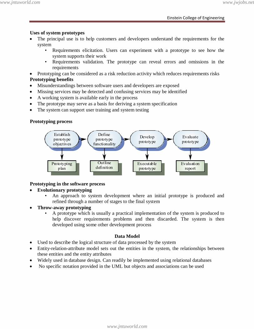
Prototyping process
Prototyping in the software process
Evolutionary prototyping
• An approach to system development where an initial prototype is produced and
refined through a number of stages to the final system
Throw-away prototyping
• A prototype which is usually a practical implementation of the system is produced to
help discover requirements problems and then discarded. The system is then
developed using some other development process
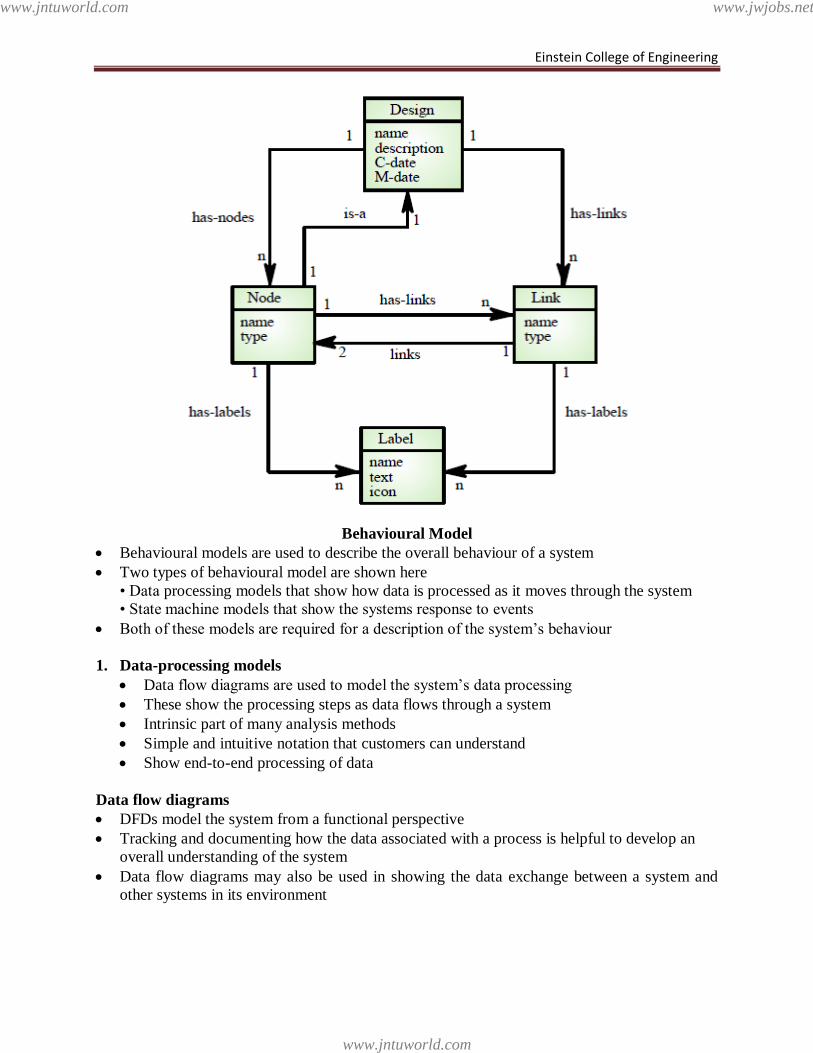
Data Model
Used to describe the logical structure of data processed by the system
Entity-relation-attribute model sets out the entities in the system, the relationships between
these entities and the entity attributes
Widely used in database design. Can readily be implemented using relational databases
No specific notation provided in the UML but objects and associations can be used
Establishprototypeobjectives
Defineprototype
functionality
Developprototype
Evaluateprototype
Prototypingplan
Outlinedefinition
Executableprototype
Evaluationreport
www.jntuworld.com
www.jntuworld.com
www.jwjobs.net
Einstein College of Engineering
Behavioural Model
Behavioural models are used to describe the overall behaviour of a system
Two types of behavioural model are shown here
• Data processing models that show how data is processed as it moves through the system
• State machine models that show the systems response to events
Both of these models are required for a description of the system‘s behaviour
1. Data-processing models
Data flow diagrams are used to model the system‘s data processing
These show the processing steps as data flows through a system
Intrinsic part of many analysis methods
Simple and intuitive notation that customers can understand
Show end-to-end processing of data
Data flow diagrams
DFDs model the system from a functional perspective
Tracking and documenting how the data associated with a process is helpful to develop an
overall understanding of the system
Data flow diagrams may also be used in showing the data exchange between a system and
other systems in its environment
www.jntuworld.com
www.jntuworld.com
www.jwjobs.net
Einstein College of Engineering
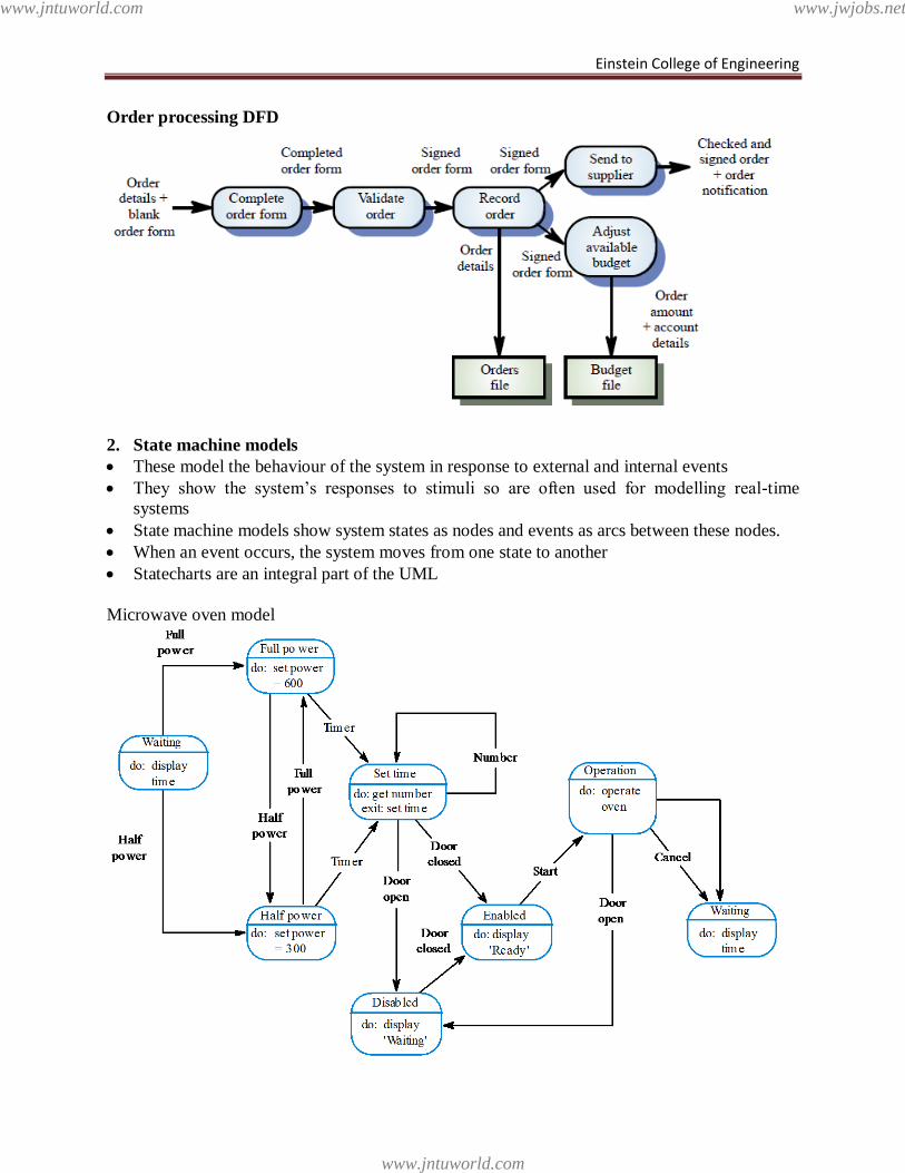
Order processing DFD
2. State machine models
These model the behaviour of the system in response to external and internal events
They show the system‘s responses to stimuli so are often used for modelling real-time
systems
State machine models show system states as nodes and events as arcs between these nodes.
When an event occurs, the system moves from one state to another
Statecharts are an integral part of the UML
Microwave oven model
www.jntuworld.com
www.jntuworld.com
www.jwjobs.net
Einstein College of Engineering
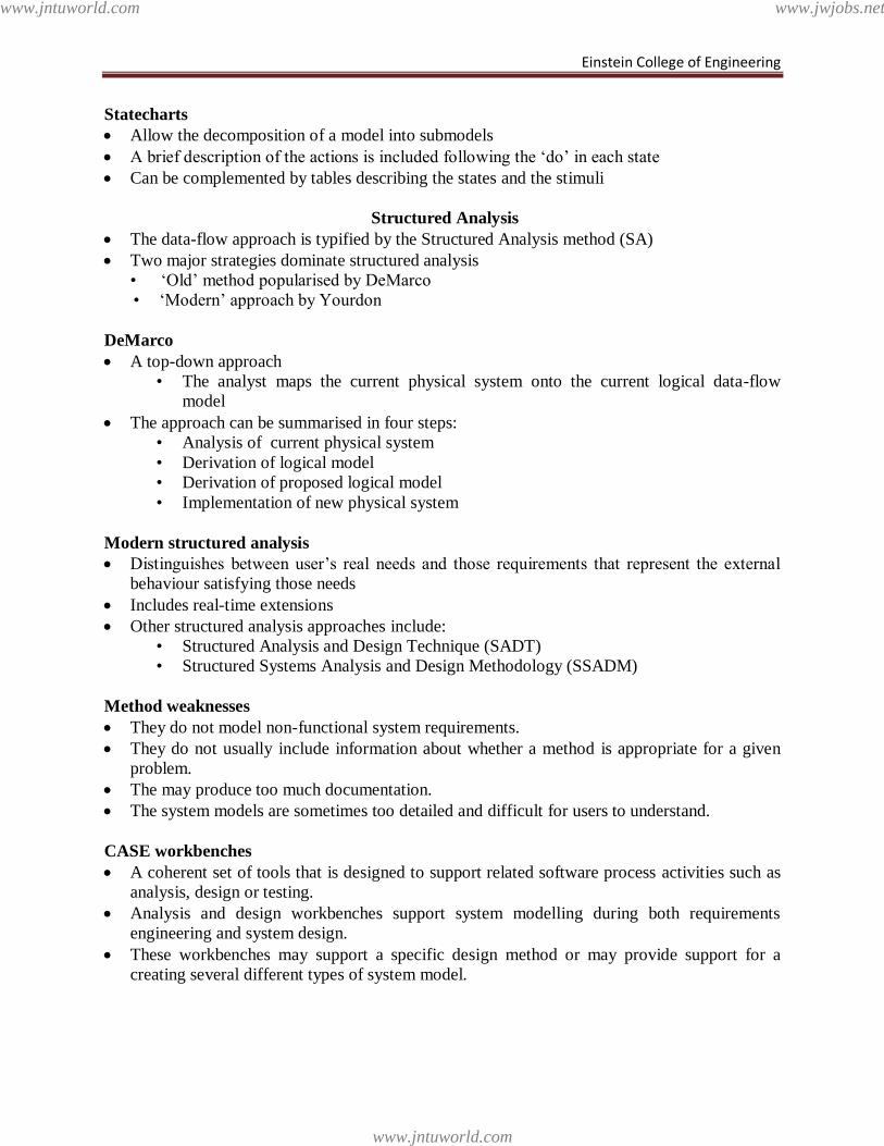
Statecharts
Allow the decomposition of a model into submodels
A brief description of the actions is included following the ‗do‘ in each state
Can be complemented by tables describing the states and the stimuli
Structured Analysis
The data-flow approach is typified by the Structured Analysis method (SA)
Two major strategies dominate structured analysis
• ‗Old‘ method popularised by DeMarco
• ‗Modern‘ approach by Yourdon
DeMarco
A top-down approach
• The analyst maps the current physical system onto the current logical data-flow
model
The approach can be summarised in four steps:
• Analysis of current physical system
• Derivation of logical model
• Derivation of proposed logical model
• Implementation of new physical system
Modern structured analysis
Distinguishes between user‘s real needs and those requirements that represent the external
behaviour satisfying those needs
Includes real-time extensions
Other structured analysis approaches include:
• Structured Analysis and Design Technique (SADT)
• Structured Systems Analysis and Design Methodology (SSADM)
Method weaknesses
They do not model non-functional system requirements.
They do not usually include information about whether a method is appropriate for a given
problem.
The may produce too much documentation.
The system models are sometimes too detailed and difficult for users to understand.
CASE workbenches
A coherent set of tools that is designed to support related software process activities such as
analysis, design or testing.
Analysis and design workbenches support system modelling during both requirements
engineering and system design.
These workbenches may support a specific design method or may provide support for a
creating several different types of system model.
www.jntuworld.com
www.jntuworld.com
www.jwjobs.net
Einstein College of Engineering
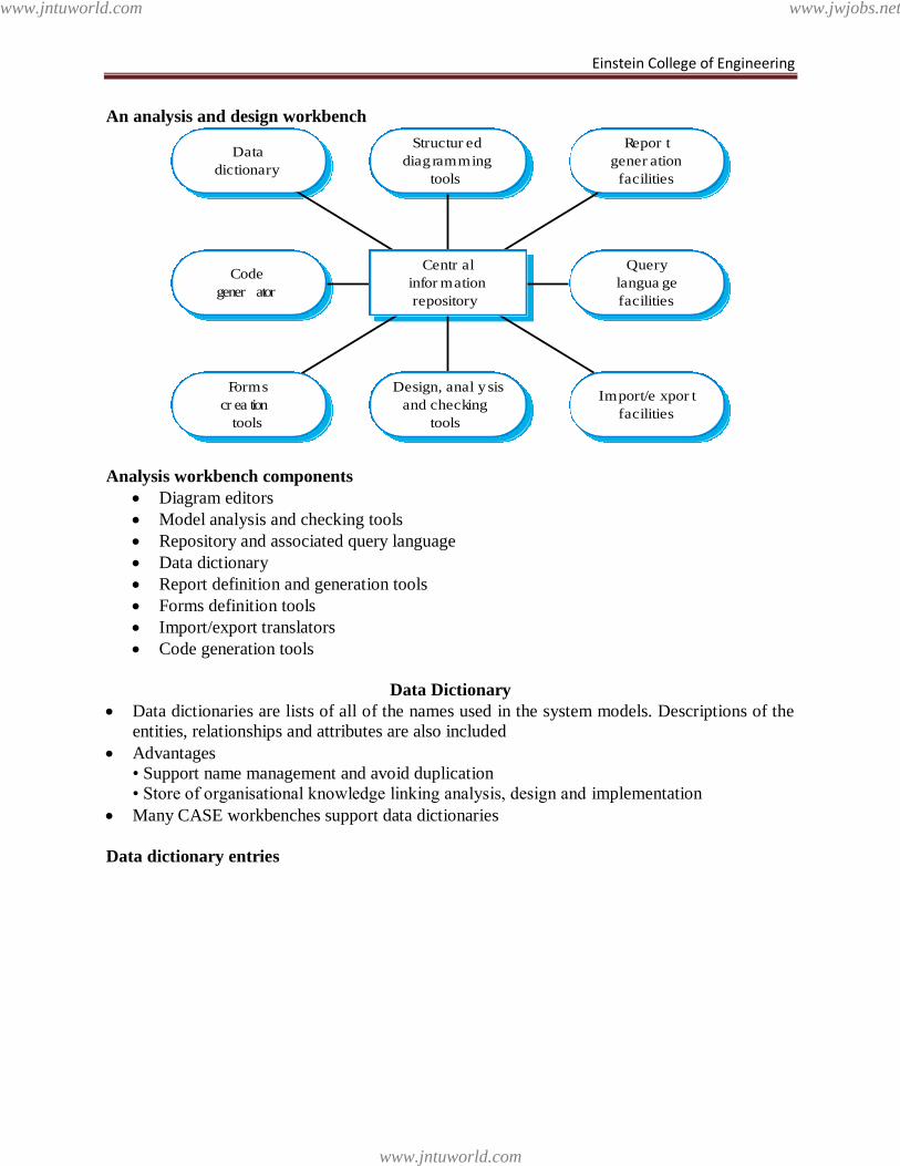
An analysis and design workbench
Analysis workbench components
Diagram editors
Model analysis and checking tools
Repository and associated query language
Data dictionary
Report definition and generation tools
Forms definition tools
Import/export translators
Code generation tools
Data Dictionary
Data dictionaries are lists of all of the names used in the system models. Descriptions of the
entities, relationships and attributes are also included
Advantages
• Support name management and avoid duplication
• Store of organisational knowledge linking analysis, design and implementation
Many CASE workbenches support data dictionaries
Data dictionary entries
Centr al
infor mation
repository
Code
gener ator
Query
langua ge
facilities
Structur ed
diag ramming
tools
Data
dictionary
Repor t
gener ation
facilities
Design, anal y sis
and checking
tools
Forms
cr ea tion
tools
Import/e xpor t
facilities
www.jntuworld.com
www.jntuworld.com
www.jwjobs.net
Einstein College of Engineering
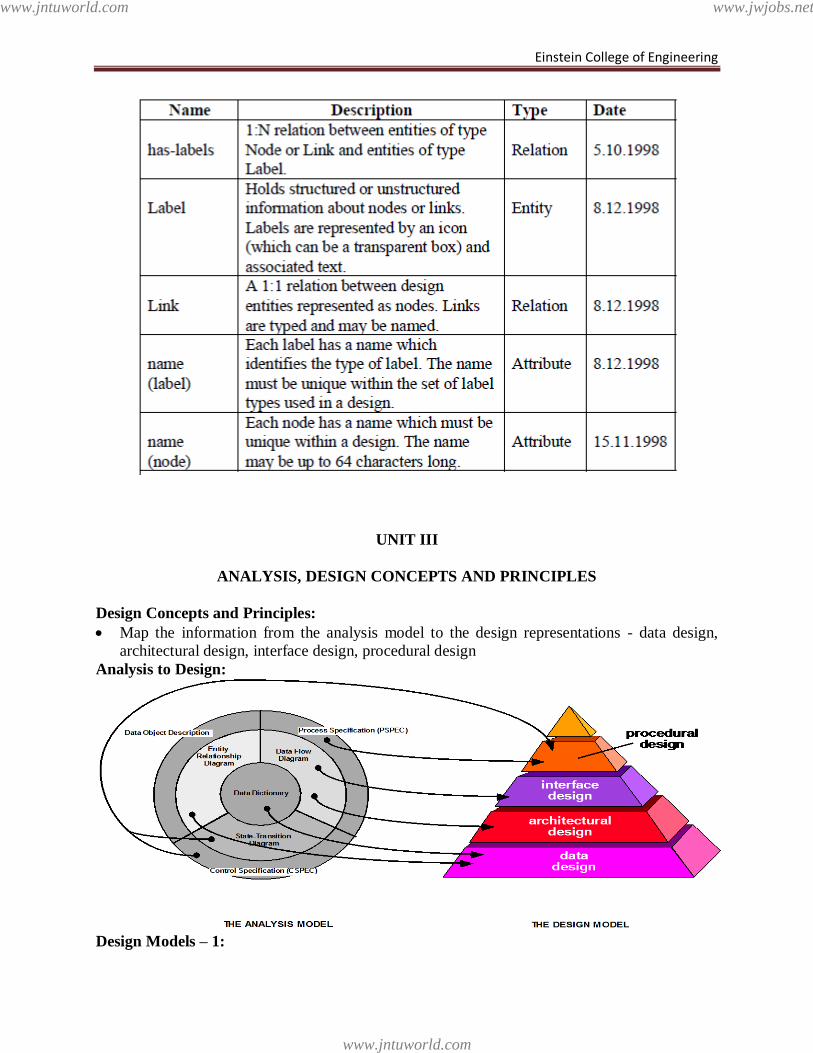
UNIT III
ANALYSIS, DESIGN CONCEPTS AND PRINCIPLES
Design Concepts and Principles:
Map the information from the analysis model to the design representations - data design,
architectural design, interface design, procedural design
Analysis to Design:
Design Models – 1:
www.jntuworld.com
www.jntuworld.com
www.jwjobs.net
Einstein College of Engineering
• Data Design
– created by transforming the data dictionary and ERD into implementation data
structures
– requires as much attention as algorithm design
• Architectural Design
– derived from the analysis model and the subsystem interactions defined in the
DFD
• Interface Design
– derived from DFD and CFD
– describes software elements communication with
• other software elements
• other systems
• human users
Design Models – 2 :
• Procedure-level design
– created by transforming the structural elements defined by the software
architecture into procedural descriptions of software components
– Derived from information in the PSPEC, CSPEC, and STD
Design Principles – 1:
• Process should not suffer from tunnel vision – consider alternative approaches
• Design should be traceable to analysis model
• Do not try to reinvent the wheel
- use design patterns ie reusable components
• Design should exhibit both uniformity and integration
• Should be structured to accommodate changes
Design Principles – 2 :
• Design is not coding and coding is not design
• Should be structured to degrade gently, when bad data, events, or operating conditions
are encountered
• Needs to be assessed for quality as it is being created
• Needs to be reviewed to minimize conceptual (semantic) errors
Design Concepts -1 :
• Abstraction
– allows designers to focus on solving a problem without being concerned about
irrelevant lower level details
Procedural abstraction is a named sequence of instructions that has a specific and limited
function
e.g open a door
Open implies a long sequence of procedural steps
data abstraction is collection of data that describes a data object
e.g door type, opening mech, weight,dimen
Design Concepts -2 :
• Design Patterns
– description of a design structure that solves a particular design problem within a
specific context and its impact when applied
Design Concepts -3 :
www.jntuworld.com
www.jntuworld.com
www.jwjobs.net
Einstein College of Engineering
• Software Architecture
– overall structure of the software components and the ways in which that structure
– provides conceptual integrity for a system
Design Concepts -4 :
• Information Hiding
– information (data and procedure) contained within a module is inaccessible to
modules that have no need for such information
• Functional Independence
– achieved by developing modules with single-minded purpose and an aversion to
excessive interaction with other models
Refactoring – Design concepts :
• Fowler [FOW99] defines refactoring in the following manner:
– "Refactoring is the process of changing a software system in such a way that it
does not alter the external behavior of the code [design] yet improves its internal
structure.‖
• When software is refectories, the existing design is examined for
– redundancy
– unused design elements
– inefficient or unnecessary algorithms
– poorly constructed or inappropriate data structures
– or any other design failure that can be corrected to yield a better design.
Design Concepts – 4 :
• Objects
– encapsulate both data and data manipulation procedures needed to describe the
content and behavior of a real world entity
• Class
– generalized description (template or pattern) that describes a collection of similar
objects
• Inheritance
– provides a means for allowing subclasses to reuse existing superclass data and
procedures; also provides mechanism for propagating changes
Design Concepts – 5:
• Messages
– the means by which objects exchange information with one another
• Polymorphism
– a mechanism that allows several objects in an class hierarchy to have different
methods with the same name
– instances of each subclass will be free to respond to messages by calling their own
version of the method
Modular Design Methodology Evaluation – 1:
Modularity
– the degree to which software can be understood by examining its components
independently of one another
• Modular decomposability
– provides systematic means for breaking problem into sub problems
www.jntuworld.com
www.jntuworld.com
www.jwjobs.net
Einstein College of Engineering
• Modular compos ability
– supports reuse of existing modules in new systems
• Modular understandability
– module can be understood as a stand-alone unit
Modular Design Methodology Evaluation – 2:
• Modular continuity
– module change side-effects minimized
• Modular protection
– processing error side-effects minimized
Effective Modular Design:
• Functional independence
– modules have high cohesion and low coupling
• Cohesion
– qualitative indication of the degree to which a module focuses on just one thing
• Coupling
– qualitative indication of the degree to which a module is connected to other
modules and to the outside world
Architectural Design:
Why Architecture?
The architecture is not the operational software. Rather, it is a representation that enables a
software engineer to:
(1) analyze the effectiveness of the design in meeting its stated requirements,
(2) consider architectural alternatives at a stage when making design changes is still relatively
easy, and
(3) reduce the risks associated with the construction of the software.
Importance :
• Software architecture representations enable communications among stakeholders
• Architecture highlights early design decisions that will have a profound impact on the
ultimate success of the system as an operational entity
• The architecture constitutes an intellectually graspable model of how the system is
structured and how its components work together
Architectural Styles – 1:
• Data centered
– file or database lies at the center of this architecture and is accessed frequently by
other components that modify data
Architectural Styles – 2:
• Data flow
– input data is transformed by a series of computational components into output
data
– Pipe and filter pattern has a set of components called filters, connected by pipes
that transmit data from one component to the next.
– If the data flow degenerates into a single line of transforms, it is termed batch
sequential
• Object-oriented
– components of system encapsulate data and operations, communication between
components is by message passing
www.jntuworld.com
www.jntuworld.com
www.jwjobs.net
Einstein College of Engineering
• Layered
– several layers are defined
– each layer performs operations that become closer to the machine instruction set
in the lower layers
Architectural Styles – 3:
Call and return
– program structure decomposes function into control hierarchy with main program
invoking several subprograms
Software Architecture Design – 1:
• Software to be developed must be put into context
– model external entities and define interfaces
• Identify architectural archetypes
– collection of abstractions that must be modeled if the system is to be constructed
Object oriented Architecture :
• The components of a system encapsulate data and the operations that must be applied to
manipulate the data. Communication and coordination between components is
accomplished via message passing
Software Architecture Design – 2:
• Specify structure of the system
– define and refine the software components needed to implement each archetype
• Continue the process iteratively until a complete architectural structure has been derived
Layered Architecture:
• Number of different layers are defined, each accomplishing operations that progressively
become closer to the machine instruction set
• At the outer layer –components service user interface operations.
• At the inner layer – components perform operating system interfacing.
• Intermediate layers provide utility services and application software function
Architecture Tradeoff Analysis – 1:
1. Collect scenarios
2. Elicit requirements, constraints, and environmental description
3. Describe architectural styles/patterns chosen to address scenarios and requirements
• module view
• process view
• data flow view
Architecture Tradeoff Analysis – 2:
4. Evaluate quality attributes independently (e.g. reliability, performance, security,
maintainability, flexibility, testability, portability, reusability, interoperability)
5. Identify sensitivity points for architecture
• any attributes significantly affected by changing in the architecture
Refining Architectural Design:
• Processing narrative developed for each module
• Interface description provided for each module
• Local and global data structures are defined
• Design restrictions/limitations noted
• Design reviews conducted
www.jntuworld.com
www.jntuworld.com
www.jwjobs.net
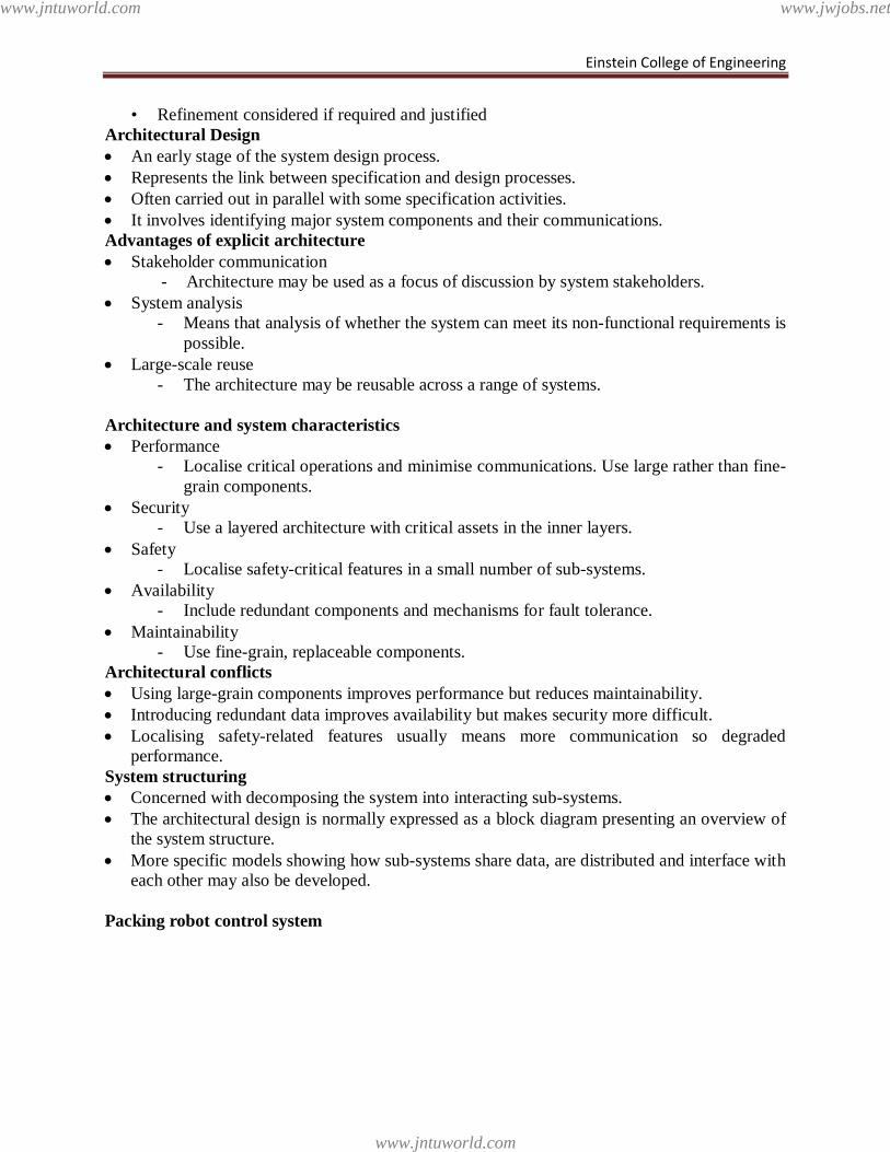
Einstein College of Engineering
• Refinement considered if required and justified
Architectural Design
An early stage of the system design process.
Represents the link between specification and design processes.
Often carried out in parallel with some specification activities.
It involves identifying major system components and their communications.
Advantages of explicit architecture
Stakeholder communication
- Architecture may be used as a focus of discussion by system stakeholders.
System analysis
- Means that analysis of whether the system can meet its non-functional requirements is
possible.
Large-scale reuse
- The architecture may be reusable across a range of systems.
Architecture and system characteristics
Performance
- Localise critical operations and minimise communications. Use large rather than fine-
grain components.
Security
- Use a layered architecture with critical assets in the inner layers.
Safety
- Localise safety-critical features in a small number of sub-systems.
Availability
- Include redundant components and mechanisms for fault tolerance.
Maintainability
- Use fine-grain, replaceable components.
Architectural conflicts
Using large-grain components improves performance but reduces maintainability.
Introducing redundant data improves availability but makes security more difficult.
Localising safety-related features usually means more communication so degraded
performance.
System structuring
Concerned with decomposing the system into interacting sub-systems.
The architectural design is normally expressed as a block diagram presenting an overview of
the system structure.
More specific models showing how sub-systems share data, are distributed and interface with
each other may also be developed.
Packing robot control system
www.jntuworld.com
www.jntuworld.com
www.jwjobs.net
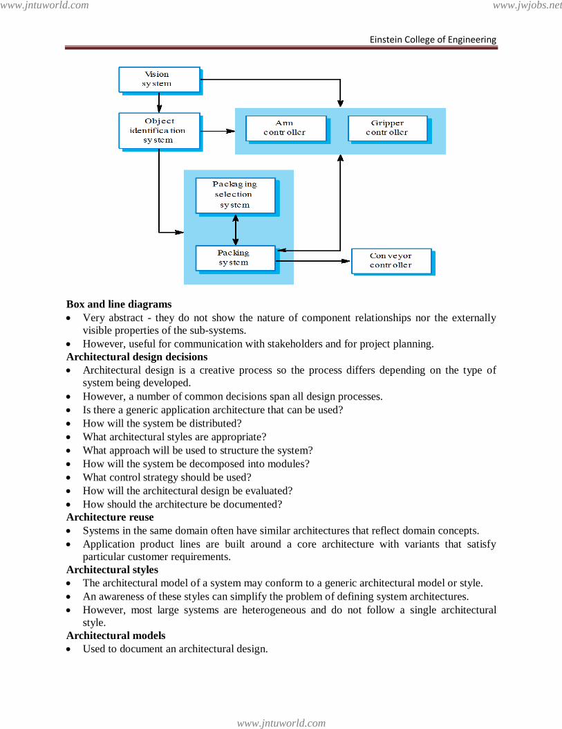
Einstein College of Engineering
Box and line diagrams
Very abstract - they do not show the nature of component relationships nor the externally
visible properties of the sub-systems.
However, useful for communication with stakeholders and for project planning.
Architectural design decisions
Architectural design is a creative process so the process differs depending on the type of
system being developed.
However, a number of common decisions span all design processes.
Is there a generic application architecture that can be used?
How will the system be distributed?
What architectural styles are appropriate?
What approach will be used to structure the system?
How will the system be decomposed into modules?
What control strategy should be used?
How will the architectural design be evaluated?
How should the architecture be documented?
Architecture reuse
Systems in the same domain often have similar architectures that reflect domain concepts.
Application product lines are built around a core architecture with variants that satisfy
particular customer requirements.
Architectural styles
The architectural model of a system may conform to a generic architectural model or style.
An awareness of these styles can simplify the problem of defining system architectures.
However, most large systems are heterogeneous and do not follow a single architectural
style.
Architectural models
Used to document an architectural design.
www.jntuworld.com
www.jntuworld.com
www.jwjobs.net
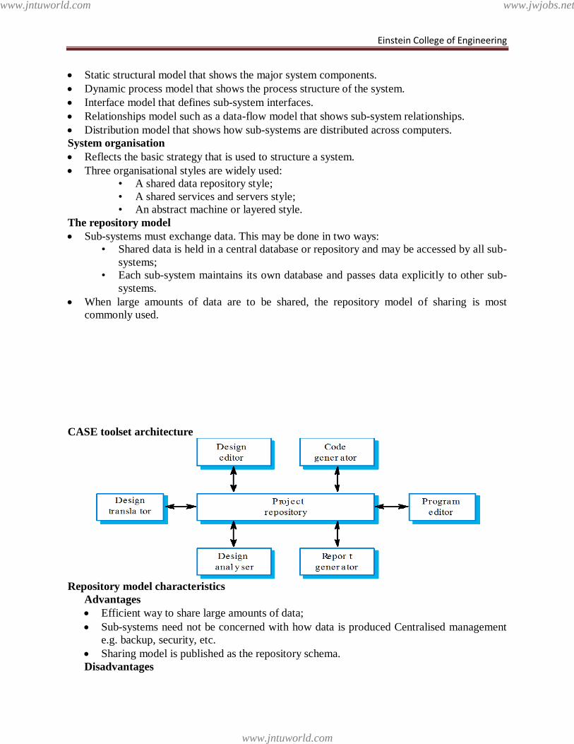
Einstein College of Engineering
Static structural model that shows the major system components.
Dynamic process model that shows the process structure of the system.
Interface model that defines sub-system interfaces.
Relationships model such as a data-flow model that shows sub-system relationships.
Distribution model that shows how sub-systems are distributed across computers.
System organisation
Reflects the basic strategy that is used to structure a system.
Three organisational styles are widely used:
• A shared data repository style;
• A shared services and servers style;
• An abstract machine or layered style.
The repository model
Sub-systems must exchange data. This may be done in two ways:
• Shared data is held in a central database or repository and may be accessed by all sub-
systems;
• Each sub-system maintains its own database and passes data explicitly to other sub-
systems.
When large amounts of data are to be shared, the repository model of sharing is most
commonly used.
CASE toolset architecture
Repository model characteristics
Advantages
Efficient way to share large amounts of data;
Sub-systems need not be concerned with how data is produced Centralised management
e.g. backup, security, etc.
Sharing model is published as the repository schema.
Disadvantages
www.jntuworld.com
www.jntuworld.com
www.jwjobs.net
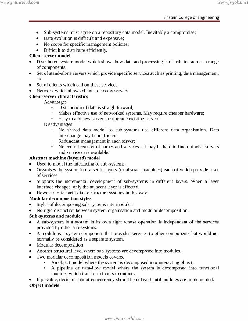
Einstein College of Engineering
Sub-systems must agree on a repository data model. Inevitably a compromise;
Data evolution is difficult and expensive;
No scope for specific management policies;
Difficult to distribute efficiently.
Client-server model
Distributed system model which shows how data and processing is distributed across a range
of components.
Set of stand-alone servers which provide specific services such as printing, data management,
etc.
Set of clients which call on these services.
Network which allows clients to access servers.
Client-server characteristics
Advantages
• Distribution of data is straightforward;
• Makes effective use of networked systems. May require cheaper hardware;
• Easy to add new servers or upgrade existing servers.
Disadvantages
• No shared data model so sub-systems use different data organisation. Data
interchange may be inefficient;
• Redundant management in each server;
• No central register of names and services - it may be hard to find out what servers
and services are available.
Abstract machine (layered) model
Used to model the interfacing of sub-systems.
Organises the system into a set of layers (or abstract machines) each of which provide a set
of services.
Supports the incremental development of sub-systems in different layers. When a layer
interface changes, only the adjacent layer is affected.
However, often artificial to structure systems in this way.
Modular decomposition styles
Styles of decomposing sub-systems into modules.
No rigid distinction between system organisation and modular decomposition.
Sub-systems and modules
A sub-system is a system in its own right whose operation is independent of the services
provided by other sub-systems.
A module is a system component that provides services to other components but would not
normally be considered as a separate system.
Modular decomposition
Another structural level where sub-systems are decomposed into modules.
Two modular decomposition models covered
• An object model where the system is decomposed into interacting object;
• A pipeline or data-flow model where the system is decomposed into functional
modules which transform inputs to outputs.
If possible, decisions about concurrency should be delayed until modules are implemented.
Object models
www.jntuworld.com
www.jntuworld.com
www.jwjobs.net
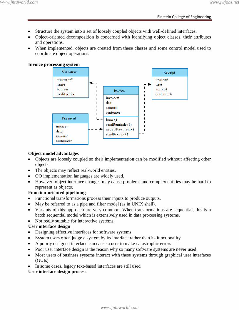
Einstein College of Engineering
Structure the system into a set of loosely coupled objects with well-defined interfaces.
Object-oriented decomposition is concerned with identifying object classes, their attributes
and operations.
When implemented, objects are created from these classes and some control model used to
coordinate object operations.
Invoice processing system
Object model advantages
Objects are loosely coupled so their implementation can be modified without affecting other
objects.
The objects may reflect real-world entities.
OO implementation languages are widely used.
However, object interface changes may cause problems and complex entities may be hard to
represent as objects.
Function-oriented pipelining
Functional transformations process their inputs to produce outputs.
May be referred to as a pipe and filter model (as in UNIX shell).
Variants of this approach are very common. When transformations are sequential, this is a
batch sequential model which is extensively used in data processing systems.
Not really suitable for interactive systems.
User interface design
Designing effective interfaces for software systems
System users often judge a system by its interface rather than its functionality
A poorly designed interface can cause a user to make catastrophic errors
Poor user interface design is the reason why so many software systems are never used
Most users of business systems interact with these systems through graphical user interfaces
(GUIs)
In some cases, legacy text-based interfaces are still used
User interface design process
www.jntuworld.com
www.jntuworld.com
www.jwjobs.net
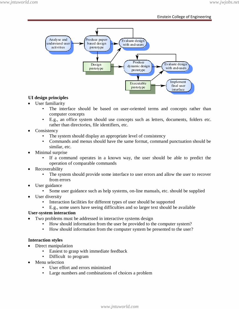
Einstein College of Engineering
UI design principles
User familiarity
• The interface should be based on user-oriented terms and concepts rather than
computer concepts
• E.g., an office system should use concepts such as letters, documents, folders etc.
rather than directories, file identifiers, etc.
Consistency
• The system should display an appropriate level of consistency
• Commands and menus should have the same format, command punctuation should be
similar, etc.
Minimal surprise
• If a command operates in a known way, the user should be able to predict the
operation of comparable commands
Recoverability
• The system should provide some interface to user errors and allow the user to recover
from errors
User guidance
• Some user guidance such as help systems, on-line manuals, etc. should be supplied
User diversity
• Interaction facilities for different types of user should be supported
• E.g., some users have seeing difficulties and so larger text should be available
User-system interaction
Two problems must be addressed in interactive systems design
• How should information from the user be provided to the computer system?
• How should information from the computer system be presented to the user?
Interaction styles
Direct manipulation
• Easiest to grasp with immediate feedback
• Difficult to program
Menu selection
• User effort and errors minimized
• Large numbers and combinations of choices a problem
Executableprototype
Designprototype
Produce paper-based design
prototype
Producedynamic design
prototype
Evaluate designwith end-users
Implementfinal userinterface
Evaluate designwith end-users
Analyse andunderstand user
activities
www.jntuworld.com
www.jntuworld.com
www.jwjobs.net
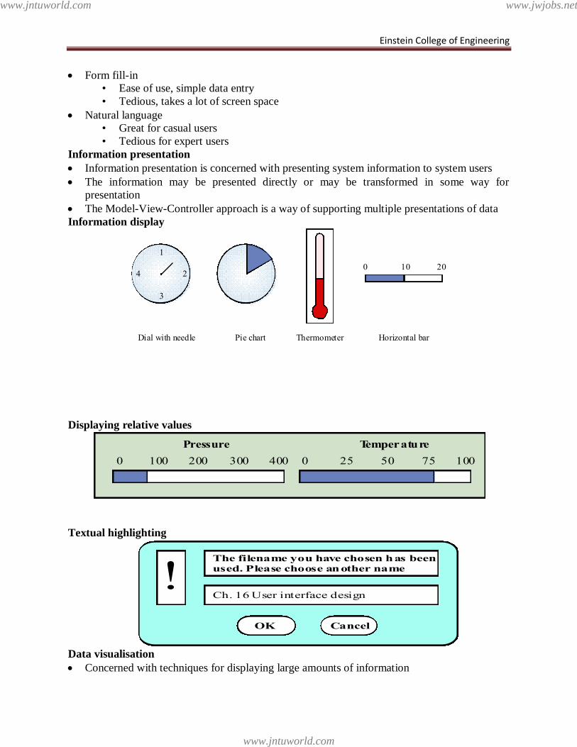
Einstein College of Engineering
Form fill-in
• Ease of use, simple data entry
• Tedious, takes a lot of screen space
Natural language
• Great for casual users
• Tedious for expert users
Information presentation
Information presentation is concerned with presenting system information to system users
The information may be presented directly or may be transformed in some way for
presentation
The Model-View-Controller approach is a way of supporting multiple presentations of data
Information display
Displaying relative values
Textual highlighting
Data visualisation
Concerned with techniques for displaying large amounts of information
1
3
4 20 10 20
Dial with needle Pie chart Thermometer Horizontal bar
0 100 200 300 400 0 25 50 75 100
Pressure Temperature
The filename you have chosen has beenused. Please choose another name
Ch. 16 User interface design!
OK Cancel
www.jntuworld.com
www.jntuworld.com
www.jwjobs.net
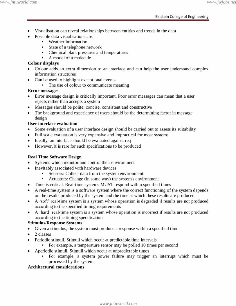
Einstein College of Engineering
Visualisation can reveal relationships between entities and trends in the data
Possible data visualisations are:
• Weather information
• State of a telephone network
• Chemical plant pressures and temperatures
• A model of a molecule
Colour displays
Colour adds an extra dimension to an interface and can help the user understand complex
information structures
Can be used to highlight exceptional events
• The use of colour to communicate meaning
Error messages
Error message design is critically important. Poor error messages can mean that a user
rejects rather than accepts a system
Messages should be polite, concise, consistent and constructive
The background and experience of users should be the determining factor in message
design
User interface evaluation
Some evaluation of a user interface design should be carried out to assess its suitability
Full scale evaluation is very expensive and impractical for most systems
Ideally, an interface should be evaluated against req
However, it is rare for such specifications to be produced
Real Time Software Design
Systems which monitor and control their environment
Inevitably associated with hardware devices
• Sensors: Collect data from the system environment
• Actuators: Change (in some way) the system's environment
Time is critical. Real-time systems MUST respond within specified times
A real-time system is a software system where the correct functioning of the system depends
on the results produced by the system and the time at which these results are produced
A ‗soft‘ real-time system is a system whose operation is degraded if results are not produced
according to the specified timing requirements
A ‗hard‘ real-time system is a system whose operation is incorrect if results are not produced
according to the timing specification
Stimulus/Response Systems
Given a stimulus, the system must produce a response within a specified time
2 classes
Periodic stimuli. Stimuli which occur at predictable time intervals
• For example, a temperature sensor may be polled 10 times per second
Aperiodic stimuli. Stimuli which occur at unpredictable times
• For example, a system power failure may trigger an interrupt which must be
processed by the system
Architectural considerations
www.jntuworld.com
www.jntuworld.com
www.jwjobs.net
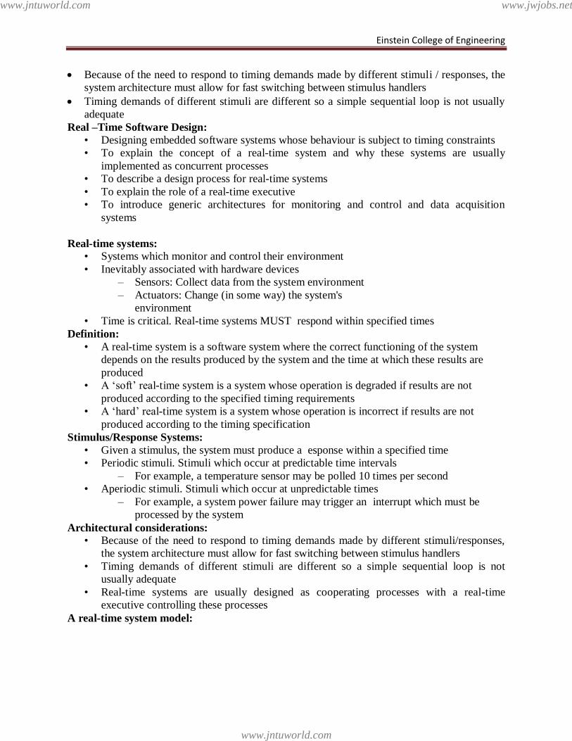
Einstein College of Engineering
Because of the need to respond to timing demands made by different stimuli / responses, the
system architecture must allow for fast switching between stimulus handlers
Timing demands of different stimuli are different so a simple sequential loop is not usually
adequate
Real –Time Software Design:
• Designing embedded software systems whose behaviour is subject to timing constraints
• To explain the concept of a real-time system and why these systems are usually
implemented as concurrent processes
• To describe a design process for real-time systems
• To explain the role of a real-time executive
• To introduce generic architectures for monitoring and control and data acquisition
systems
Real-time systems:
• Systems which monitor and control their environment
• Inevitably associated with hardware devices
– Sensors: Collect data from the system environment
– Actuators: Change (in some way) the system's
environment
• Time is critical. Real-time systems MUST respond within specified times
Definition:
• A real-time system is a software system where the correct functioning of the system
depends on the results produced by the system and the time at which these results are
produced
• A ‗soft‘ real-time system is a system whose operation is degraded if results are not
produced according to the specified timing requirements
• A ‗hard‘ real-time system is a system whose operation is incorrect if results are not
produced according to the timing specification
Stimulus/Response Systems:
• Given a stimulus, the system must produce a esponse within a specified time
• Periodic stimuli. Stimuli which occur at predictable time intervals
– For example, a temperature sensor may be polled 10 times per second
• Aperiodic stimuli. Stimuli which occur at unpredictable times
– For example, a system power failure may trigger an interrupt which must be
processed by the system
Architectural considerations:
• Because of the need to respond to timing demands made by different stimuli/responses,
the system architecture must allow for fast switching between stimulus handlers
• Timing demands of different stimuli are different so a simple sequential loop is not
usually adequate
• Real-time systems are usually designed as cooperating processes with a real-time
executive controlling these processes
A real-time system model:
www.jntuworld.com
www.jntuworld.com
www.jwjobs.net
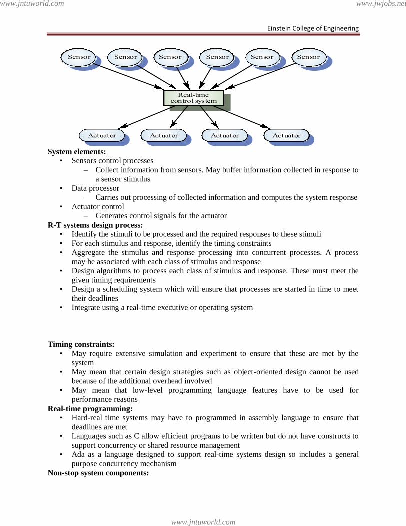
Einstein College of Engineering
System elements:
• Sensors control processes
– Collect information from sensors. May buffer information collected in response to
a sensor stimulus
• Data processor
– Carries out processing of collected information and computes the system response
• Actuator control
– Generates control signals for the actuator
R-T systems design process:
• Identify the stimuli to be processed and the required responses to these stimuli
• For each stimulus and response, identify the timing constraints
• Aggregate the stimulus and response processing into concurrent processes. A process
may be associated with each class of stimulus and response
• Design algorithms to process each class of stimulus and response. These must meet the
given timing requirements
• Design a scheduling system which will ensure that processes are started in time to meet
their deadlines
• Integrate using a real-time executive or operating system
Timing constraints:
• May require extensive simulation and experiment to ensure that these are met by the
system
• May mean that certain design strategies such as object-oriented design cannot be used
because of the additional overhead involved
• May mean that low-level programming language features have to be used for
performance reasons
Real-time programming:
• Hard-real time systems may have to programmed in assembly language to ensure that
deadlines are met
• Languages such as C allow efficient programs to be written but do not have constructs to
support concurrency or shared resource management
• Ada as a language designed to support real-time systems design so includes a general
purpose concurrency mechanism
Non-stop system components:
Real-timecontrol system
ActuatorActuator ActuatorActuator
SensorSensorSensor SensorSensorSensor
www.jntuworld.com
www.jntuworld.com
www.jwjobs.net
Einstein College of Engineering
• Configuration manager
– Responsible for the dynamic reconfiguration of the system
software and hardware. Hardware modules may be replaced and software
upgraded without stopping the systems
• Fault manager
– Responsible for detecting software and hardware faults and
taking appropriate actions (e.g. switching to backup disks) to ensure that the
system continues in operation
Burglar alarm system e.g
• A system is required to monitor sensors on doors and windows to detect the presence of
intruders in a building
• When a sensor indicates a break-in, the system switches on lights around the area and
calls police automatically
• The system should include provision for operation without a mains power supply
• Sensors
• Movement detectors, window sensors, door sensors.
• 50 window sensors, 30 door sensors and 200 movement detectors
• Voltage drop sensor
• Actions
• When an intruder is detected, police are called automatically.
• Lights are switched on in rooms with active sensors.
• An audible alarm is switched on.
• The system switches automatically to backup power when a voltage drop is
detected.
The R-T system design process:
• Identify stimuli and associated responses
• Define the timing constraints associated with each stimulus and response
• Allocate system functions to concurrent processes
• Design algorithms for stimulus processing and response generation
• Design a scheduling system which ensures that processes will always be scheduled to
meet their deadlines
Control systems:
• A burglar alarm system is primarily a monitoring system. It collects data from sensors but
no real-time actuator control
• Control systems are similar but, in response to sensor values, the system sends control
signals to actuators
• An example of a monitoring and control system is a system which monitors temperature
and switches heaters on and off
Data acquisition systems:
• Collect data from sensors for subsequent processing and analysis.
• Data collection processes and processing processes may have different periods and
deadlines.
• Data collection may be faster than processing e.g. collecting information about an
explosion.
• Circular or ring buffers are a mechanism for smoothing speed differences.
www.jntuworld.com
www.jntuworld.com
www.jwjobs.net
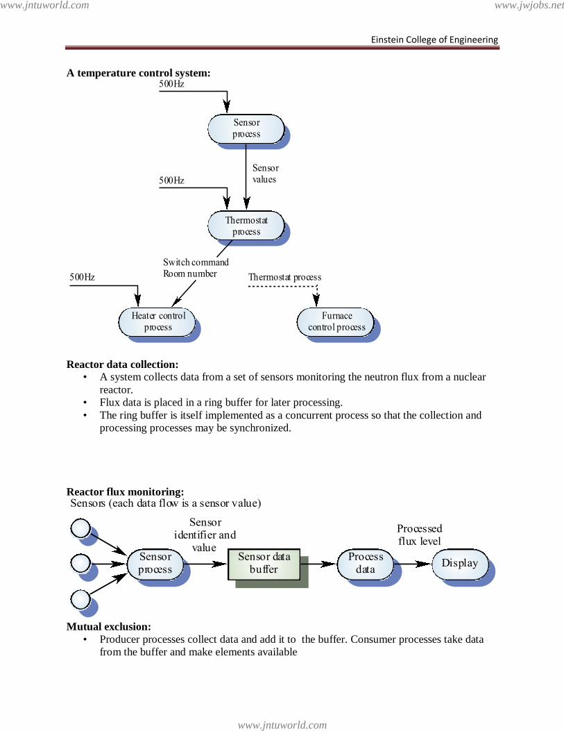
Einstein College of Engineering
A temperature control system:
Reactor data collection:
• A system collects data from a set of sensors monitoring the neutron flux from a nuclear
reactor.
• Flux data is placed in a ring buffer for later processing.
• The ring buffer is itself implemented as a concurrent process so that the collection and
processing processes may be synchronized.
Reactor flux monitoring:
Mutual exclusion:
• Producer processes collect data and add it to the buffer. Consumer processes take data
from the buffer and make elements available
Thermostatprocess
Sensorprocess
Furnacecontrol process
Heater controlprocess
500Hz
500Hz
Thermostat process500Hz
Sensorvalues
Switch commandRoom number
DisplayProcess
dataSensor data
bufferSensorprocess
Sensoridentifier and
value
Processedflux level
Sensors (each data flow is a sensor value)
www.jntuworld.com
www.jntuworld.com
www.jwjobs.net
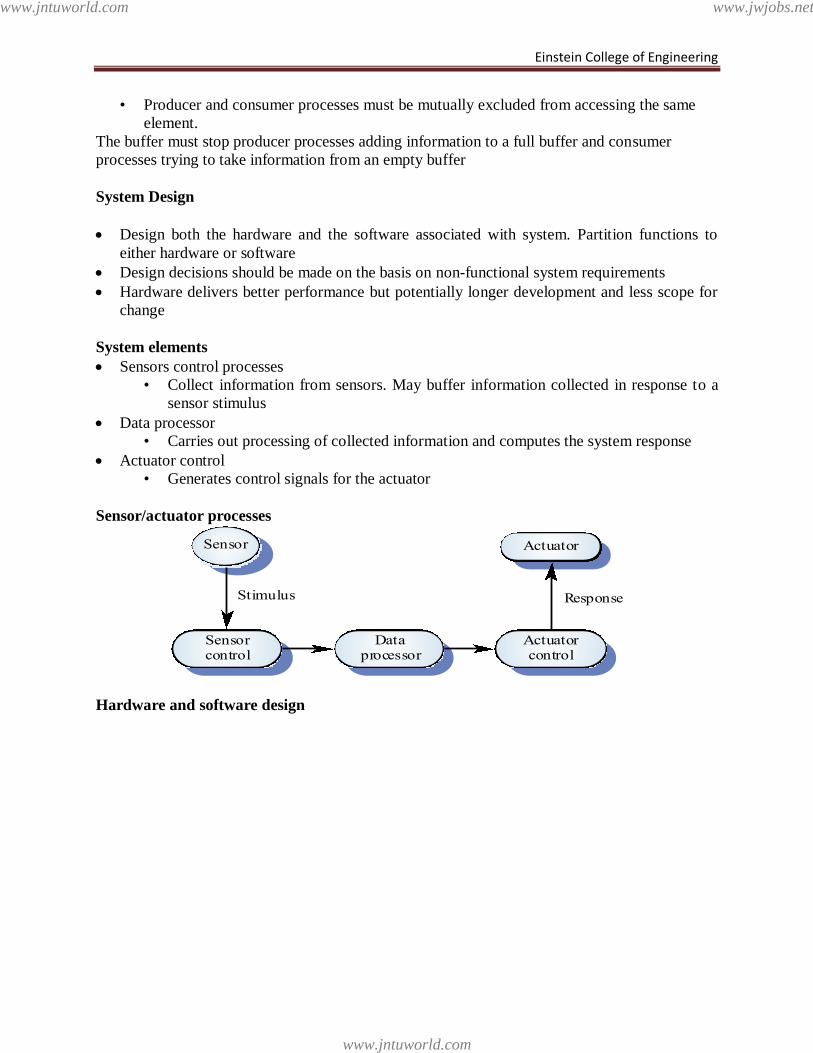
Einstein College of Engineering
• Producer and consumer processes must be mutually excluded from accessing the same
element.
The buffer must stop producer processes adding information to a full buffer and consumer
processes trying to take information from an empty buffer
System Design
Design both the hardware and the software associated with system. Partition functions to
either hardware or software
Design decisions should be made on the basis on non-functional system requirements
Hardware delivers better performance but potentially longer development and less scope for
change
System elements
Sensors control processes
• Collect information from sensors. May buffer information collected in response to a
sensor stimulus
Data processor
• Carries out processing of collected information and computes the system response
Actuator control
• Generates control signals for the actuator
Sensor/actuator processes
Hardware and software design
Dataprocessor
Actuatorcontrol
Actuator
Sensorcontrol
Sensor
Stimulus Response
www.jntuworld.com
www.jntuworld.com
www.jwjobs.net
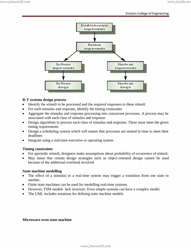
Einstein College of Engineering
R-T systems design process
Identify the stimuli to be processed and the required responses to these stimuli
For each stimulus and response, identify the timing constraints
Aggregate the stimulus and response processing into concurrent processes. A process may be
associated with each class of stimulus and response
Design algorithms to process each class of stimulus and response. These must meet the given
timing requirements
Design a scheduling system which will ensure that processes are started in time to meet their
deadlines
Integrate using a real-time executive or operating system
Timing constraints
For aperiodic stimuli, designers make assumptions about probability of occurrence of stimuli.
May mean that certain design strategies such as object-oriented design cannot be used
because of the additional overhead involved
State machine modelling
The effect of a stimulus in a real-time system may trigger a transition from one state to
another.
Finite state machines can be used for modelling real-time systems.
However, FSM models lack structure. Even simple systems can have a complex model.
The UML includes notations for defining state machine models
Microwave oven state machine
Establish systemrequirements
Partitionrequirements
Hardwarerequirements
Hardwaredesign
Softwarerequirements
Softwaredesign
www.jntuworld.com
www.jntuworld.com
www.jwjobs.net
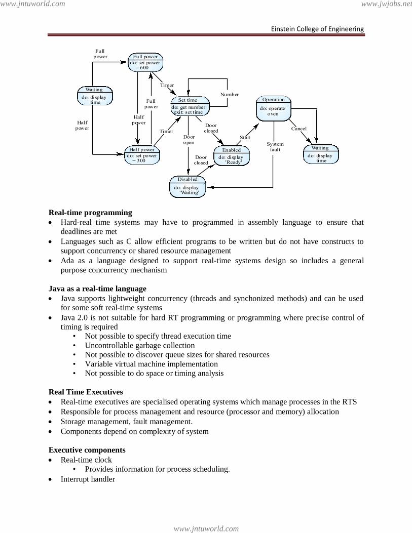
Einstein College of Engineering
Real-time programming
Hard-real time systems may have to programmed in assembly language to ensure that
deadlines are met
Languages such as C allow efficient programs to be written but do not have constructs to
support concurrency or shared resource management
Ada as a language designed to support real-time systems design so includes a general
purpose concurrency mechanism
Java as a real-time language
Java supports lightweight concurrency (threads and synchonized methods) and can be used
for some soft real-time systems
Java 2.0 is not suitable for hard RT programming or programming where precise control of
timing is required
• Not possible to specify thread execution time
• Uncontrollable garbage collection
• Not possible to discover queue sizes for shared resources
• Variable virtual machine implementation
• Not possible to do space or timing analysis
Real Time Executives
Real-time executives are specialised operating systems which manage processes in the RTS
Responsible for process management and resource (processor and memory) allocation
Storage management, fault management.
Components depend on complexity of system
Executive components
Real-time clock
• Provides information for process scheduling.
Interrupt handler
Full power
Enabled
do: operateoven
Fullpower
Halfpower
Halfpower
Fullpower
Number
TimerDooropen
Doorclosed
Doorclosed
Systemfault
Start
do: set power = 600
Half power
do: set power = 300
Set time
do: get numberexit: set time
Disabled
Operation
Timer
Cancel
Waiting
do: display time
Waiting
do: display time
do: display 'Ready'
do: display 'Waiting'
www.jntuworld.com
www.jntuworld.com
www.jwjobs.net
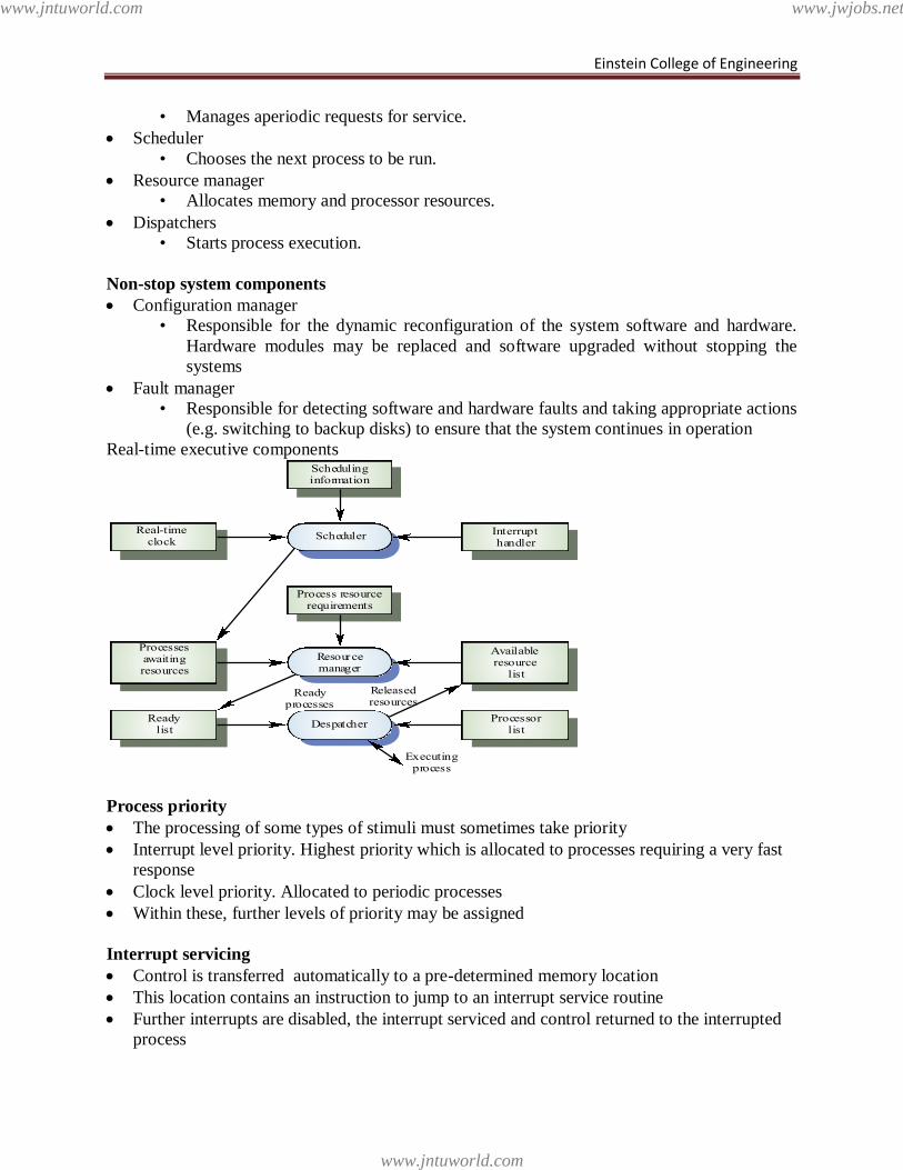
Einstein College of Engineering
• Manages aperiodic requests for service.
Scheduler
• Chooses the next process to be run.
Resource manager
• Allocates memory and processor resources.
Dispatchers
• Starts process execution.
Non-stop system components
Configuration manager
• Responsible for the dynamic reconfiguration of the system software and hardware.
Hardware modules may be replaced and software upgraded without stopping the
systems
Fault manager
• Responsible for detecting software and hardware faults and taking appropriate actions
(e.g. switching to backup disks) to ensure that the system continues in operation
Real-time executive components
Process priority
The processing of some types of stimuli must sometimes take priority
Interrupt level priority. Highest priority which is allocated to processes requiring a very fast
response
Clock level priority. Allocated to periodic processes
Within these, further levels of priority may be assigned
Interrupt servicing
Control is transferred automatically to a pre-determined memory location
This location contains an instruction to jump to an interrupt service routine
Further interrupts are disabled, the interrupt serviced and control returned to the interrupted
process
Process resourcerequirements
Scheduler
Schedulinginformation
Resourcemanager
Despatcher
Real-timeclock
Processesawaitingresources
Readylist
Interrupthandler
Availableresource
list
Processorlist
Executingprocess
Readyprocesses
Releasedresources
www.jntuworld.com
www.jntuworld.com
www.jwjobs.net
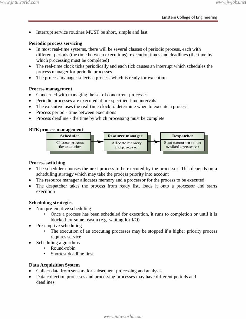
Einstein College of Engineering
Interrupt service routines MUST be short, simple and fast
Periodic process servicing
In most real-time systems, there will be several classes of periodic process, each with
different periods (the time between executions), execution times and deadlines (the time by
which processing must be completed)
The real-time clock ticks periodically and each tick causes an interrupt which schedules the
process manager for periodic processes
The process manager selects a process which is ready for execution
Process management
Concerned with managing the set of concurrent processes
Periodic processes are executed at pre-specified time intervals
The executive uses the real-time clock to determine when to execute a process
Process period - time between executions
Process deadline - the time by which processing must be complete
RTE process management
Process switching
The scheduler chooses the next process to be executed by the processor. This depends on a
scheduling strategy which may take the process priority into account
The resource manager allocates memory and a processor for the process to be executed
The despatcher takes the process from ready list, loads it onto a processor and starts
execution
Scheduling strategies
Non pre-emptive scheduling
• Once a process has been scheduled for execution, it runs to completion or until it is
blocked for some reason (e.g. waiting for I/O)
Pre-emptive scheduling
• The execution of an executing processes may be stopped if a higher priority process
requires service
Scheduling algorithms
• Round-robin
• Shortest deadline first
Data Acquisition System
Collect data from sensors for subsequent processing and analysis.
Data collection processes and processing processes may have different periods and
deadlines.
Resource manager
Allocate memoryand processor
Scheduler
Choose processfor execution
Despatcher
Start execution on anavailable processor
www.jntuworld.com
www.jntuworld.com
www.jwjobs.net
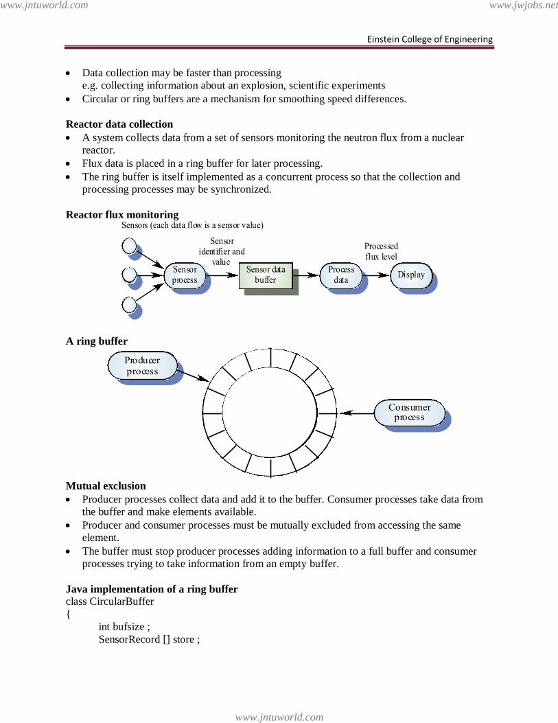
Einstein College of Engineering
Data collection may be faster than processing
e.g. collecting information about an explosion, scientific experiments
Circular or ring buffers are a mechanism for smoothing speed differences.
Reactor data collection
A system collects data from a set of sensors monitoring the neutron flux from a nuclear
reactor.
Flux data is placed in a ring buffer for later processing.
The ring buffer is itself implemented as a concurrent process so that the collection and
processing processes may be synchronized.
Reactor flux monitoring
A ring buffer
Mutual exclusion
Producer processes collect data and add it to the buffer. Consumer processes take data from
the buffer and make elements available.
Producer and consumer processes must be mutually excluded from accessing the same
element.
The buffer must stop producer processes adding information to a full buffer and consumer
processes trying to take information from an empty buffer.
Java implementation of a ring buffer class CircularBuffer
{
int bufsize ;
SensorRecord [] store ;
DisplayProcess
dataSensor data
bufferSensorprocess
Sensoridentifier and
value
Processedflux level
Sensors (each data flow is a sensor value)
Consumerprocess
Producerprocess
www.jntuworld.com
www.jntuworld.com
www.jwjobs.net
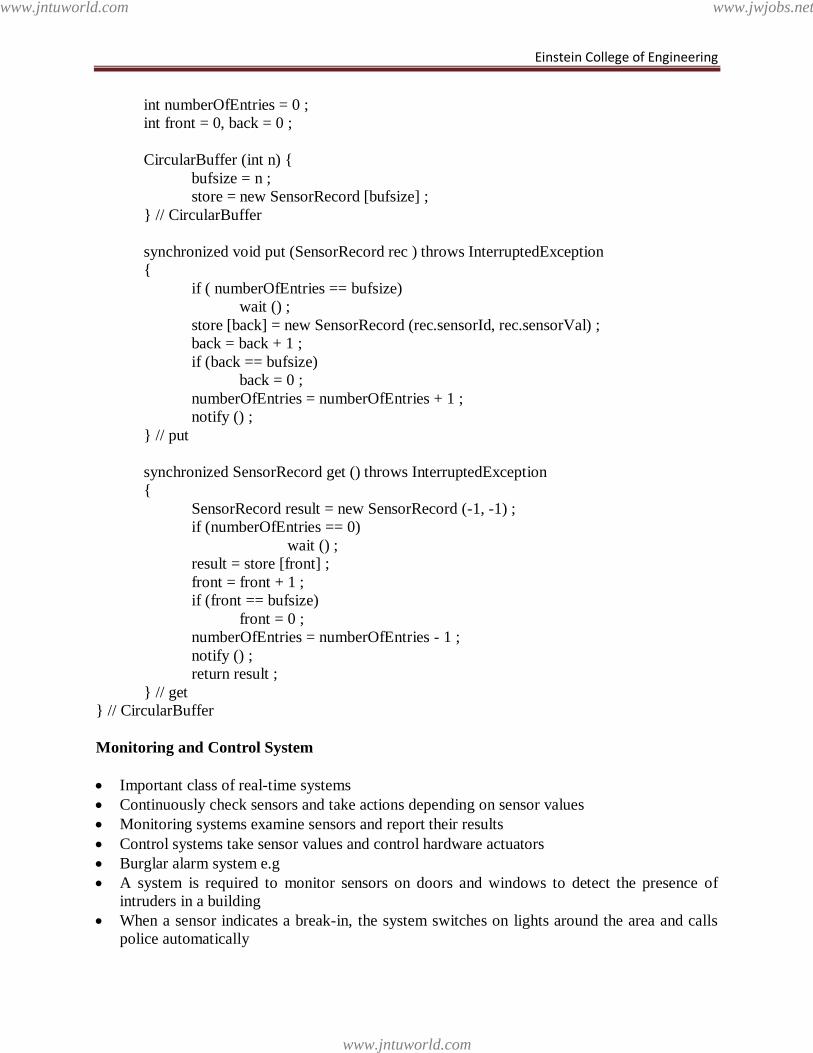
Einstein College of Engineering
int numberOfEntries = 0 ;
int front = 0, back = 0 ;
CircularBuffer (int n) {
bufsize = n ;
store = new SensorRecord [bufsize] ;
} // CircularBuffer
synchronized void put (SensorRecord rec ) throws InterruptedException
{
if ( numberOfEntries == bufsize)
wait () ;
store [back] = new SensorRecord (rec.sensorId, rec.sensorVal) ;
back = back + 1 ;
if (back == bufsize)
back = 0 ;
numberOfEntries = numberOfEntries + 1 ;
notify () ;
} // put
synchronized SensorRecord get () throws InterruptedException
{
SensorRecord result = new SensorRecord (-1, -1) ;
if (numberOfEntries == 0)
wait () ;
result = store [front] ;
front = front + 1 ;
if (front == bufsize)
front = 0 ;
numberOfEntries = numberOfEntries - 1 ;
notify () ;
return result ;
} // get
} // CircularBuffer
Monitoring and Control System
Important class of real-time systems
Continuously check sensors and take actions depending on sensor values
Monitoring systems examine sensors and report their results
Control systems take sensor values and control hardware actuators
Burglar alarm system e.g
A system is required to monitor sensors on doors and windows to detect the presence of
intruders in a building
When a sensor indicates a break-in, the system switches on lights around the area and calls
police automatically
www.jntuworld.com
www.jntuworld.com
www.jwjobs.net
Einstein College of Engineering
The system should include provision for operation without a mains power supply
Burglar alarm system
Sensors
• Movement detectors, window sensors, door sensors.
• 50 window sensors, 30 door sensors and 200 movement detectors
• Voltage drop sensor
Actions
• When an intruder is detected, police are called automatically.
• Lights are switched on in rooms with active sensors.
• An audible alarm is switched on.
• The system switches automatically to backup power when a voltage drop is detected.
The R-T system design process
Identify stimuli and associated responses
Define the timing constraints associated with each stimulus and response
Allocate system functions to concurrent processes
Design algorithms for stimulus processing and response generation
Design a scheduling system which ensures that processes will always be scheduled to meet
their deadlines
Stimuli to be processed
Power failure
• Generated by a circuit monitor. When received, the system must switch to backup
power within 50 ms
Intruder alarm
• Stimulus generated by system sensors. Response is to call the police, switch on
building lights and the audible alarm
Timing requirements
Stimulus/Response Timing requirements
Power fail interrupt The switch to backup power must be completed
within a deadline of 50 ms.
Door alarm Each door alarm should be polled twice per second.
Window alarm Each window alarm should be polled twice per
second.
Movement detector Each movement detector should be polled twice per
second.
Audible alarm The audible alarm should be switched on within 1/2
second of an alarm being raised by a sensor.
Lights switch The lights should be switched on within 1/2 second
of an alarm being raised by a sensor.
Communications The call to the police should be started within 2
seconds of an alarm being raised by a sensor.
Voice synthesiser A synthesised message should be available within 4
seconds of an alarm being raised by a sensor.
www.jntuworld.com
www.jntuworld.com
www.jwjobs.net
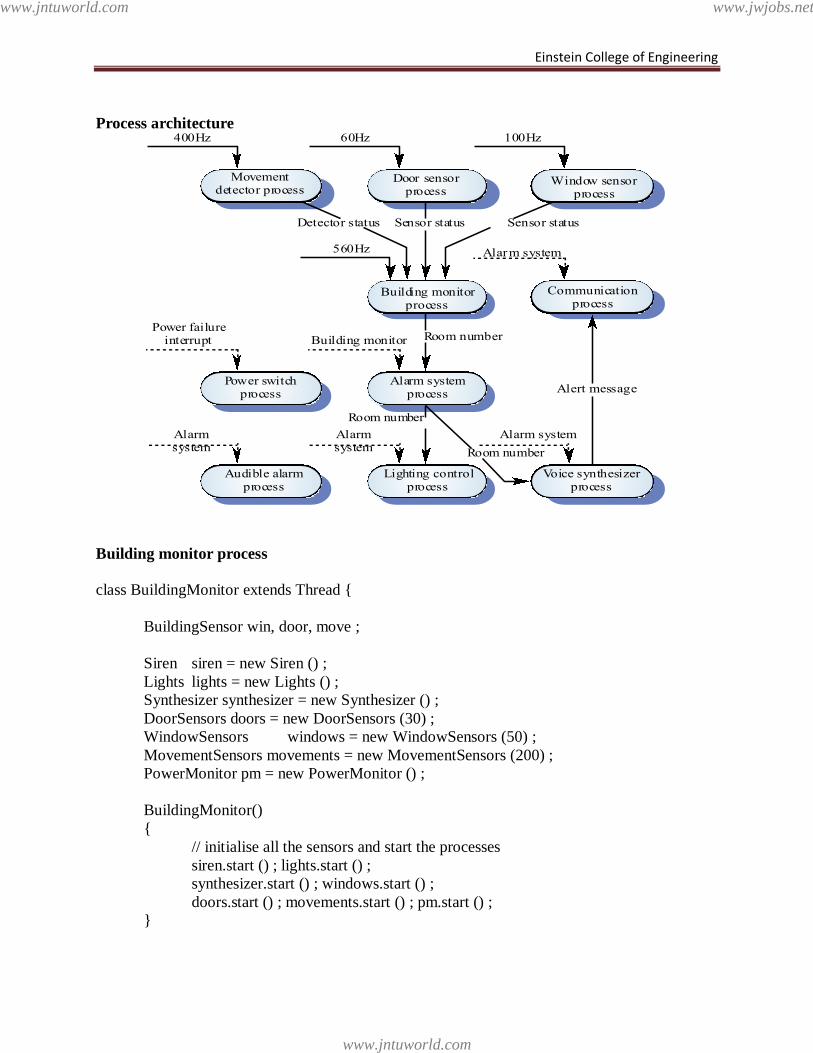
Einstein College of Engineering
Process architecture
Building monitor process
class BuildingMonitor extends Thread {
BuildingSensor win, door, move ;
Siren siren = new Siren () ;
Lights lights = new Lights () ;
Synthesizer synthesizer = new Synthesizer () ;
DoorSensors doors = new DoorSensors (30) ;
WindowSensors windows = new WindowSensors (50) ;
MovementSensors movements = new MovementSensors (200) ;
PowerMonitor pm = new PowerMonitor () ;
BuildingMonitor()
{
// initialise all the sensors and start the processes
siren.start () ; lights.start () ;
synthesizer.start () ; windows.start () ;
doors.start () ; movements.start () ; pm.start () ;
}
Lighting controlprocess
Audible alarmprocess
Voice synthesizerprocess
Alarm systemprocess
Power switchprocess
Building monitorprocess
Communicationprocess
Door sensorprocess
Movementdetector process
Window sensorprocess
560Hz
60Hz400Hz 100Hz
Power failureinterrupt
Alarmsystem
Building monitor
Alarmsystem
Alarm system
Alarm system
Detector status Sensor status Sensor status
Room number
Alert message
Room number
Room number
www.jntuworld.com
www.jntuworld.com
www.jwjobs.net
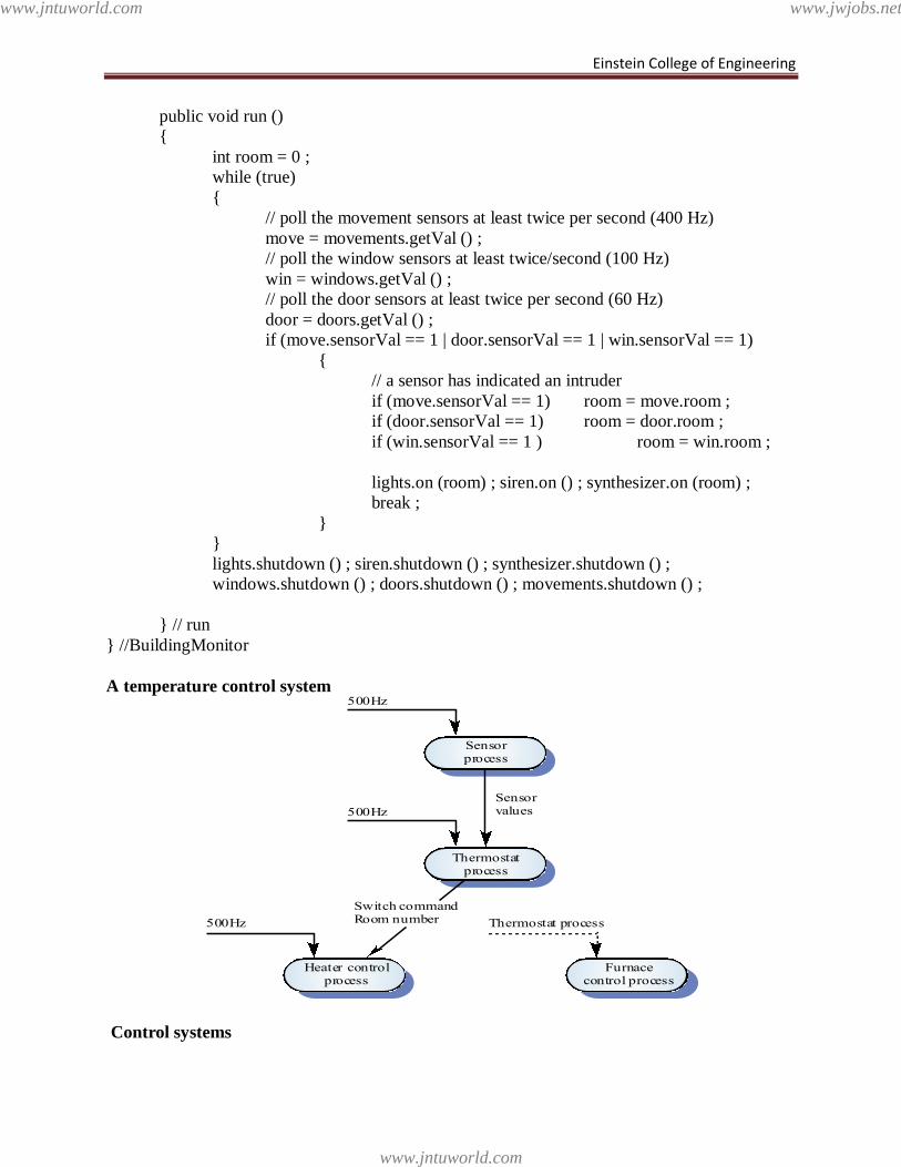
Einstein College of Engineering
public void run ()
{
int room = 0 ;
while (true)
{
// poll the movement sensors at least twice per second (400 Hz)
move = movements.getVal () ;
// poll the window sensors at least twice/second (100 Hz)
win = windows.getVal () ;
// poll the door sensors at least twice per second (60 Hz)
door = doors.getVal () ;
if (move.sensorVal == 1 | door.sensorVal == 1 | win.sensorVal == 1)
{
// a sensor has indicated an intruder
if (move.sensorVal == 1) room = move.room ;
if (door.sensorVal == 1) room = door.room ;
if (win.sensorVal == 1 ) room = win.room ;
lights.on (room) ; siren.on () ; synthesizer.on (room) ;
break ;
}
}
lights.shutdown () ; siren.shutdown () ; synthesizer.shutdown () ;
windows.shutdown () ; doors.shutdown () ; movements.shutdown () ;
} // run
} //BuildingMonitor
A temperature control system
Control systems
Thermostatprocess
Sensorprocess
Furnacecontrol process
Heater controlprocess
500Hz
500Hz
Thermostat process500Hz
Sensorvalues
Switch commandRoom number
www.jntuworld.com
www.jntuworld.com
www.jwjobs.net
Einstein College of Engineering
A burglar alarm system is primarily a monitoring system. It collects data from sensors but no
real-time actuator control
Control systems are similar but, in response to sensor values, the system sends control
signals to actuators
An example of a monitoring and control system is a system which monitors temperature and
switches heaters on and off
UNIT IV
TESTING
Taxonomy of Software Testing
Classified by purpose, software testing can be divided into: correctness testing, performance
testing, and reliability testing and security testing.
Classified by life-cycle phase, software testing can be classified into the following
categories: requirements phase testing, design phase testing, program phase testing,
evaluating test results, installation phase testing, acceptance testing and maintenance testing.
By scope, software testing can be categorized as follows: unit testing, component testing,
integration testing, and system testing.
Correctness testing
Correctness is the minimum requirement of software, the essential purpose of testing. It is
used to tell the right behavior from the wrong one. The tester may or may not know the inside
details of the software module under test, e.g. control flow, data flow, etc. Therefore, either a
white-box point of view or black-box point of view can be taken in testing software. We must
note that the black-box and white-box ideas are not limited in correctness testing only.
Black-box testing
White-box testing
Performance testing
Not all software systems have specifications on performance explicitly. But every system
will have implicit performance requirements. The software should not take infinite time or
infinite resource to execute. "Performance bugs" sometimes are used to refer to those design
problems in software that cause the system performance to degrade.
Performance has always been a great concern and a driving force of computer evolution.
Performance evaluation of a software system usually includes: resource usage, throughput,
stimulus-response time and queue lengths detailing the average or maximum number of tasks
waiting to be serviced by selected resources. Typical resources that need to be considered
include network bandwidth requirements, CPU cycles, disk space, disk access operations, and
memory usage. The goal of performance testing can be performance bottleneck identification,
performance comparison and evaluation, etc.
Reliability testing
www.jntuworld.com
www.jntuworld.com
www.jwjobs.net
Einstein College of Engineering
Software reliability refers to the probability of failure-free operation of a system. It is
related to many aspects of software, including the testing process. Directly estimating software
reliability by quantifying its related factors can be difficult. Testing is an effective sampling
method to measure software reliability. Guided by the operational profile, software testing
(usually black-box testing) can be used to obtain failure data, and an estimation model can be
further used to analyze the data to estimate the present reliability and predict future reliability.
Therefore, based on the estimation, the developers can decide whether to release the software,
and the users can decide whether to adopt and use the software. Risk of using software can also
be assessed based on reliability information.
Security testing Software quality, reliability and security are tightly coupled. Flaws in software can be
exploited by intruders to open security holes. With the development of the Internet, software
security problems are becoming even more severe.
Many critical software applications and services have integrated security measures against
malicious attacks. The purpose of security testing of these systems include identifying and
removing software flaws that may potentially lead to security violations, and validating the
effectiveness of security measures. Simulated security attacks can be performed to find
vulnerabilities.
Types of S/W Test
Acceptance testing
Testing to verify a product meets customer specified requirements. A customer usually
does this type of testing on a product that is developed externally.
Compatibility testing
This is used to ensure compatibility of an application or Web site with different browsers,
OSs, and hardware platforms. Compatibility testing can be performed manually or can be driven
by an automated functional or regression test suite.
Conformance testing
This is used to verify implementation conformance to industry standards. Producing tests
for the behavior of an implementation to be sure it provides the portability, interoperability,
and/or compatibility a standard defines.
Integration testing
Modules are typically code modules, individual applications, client and server
applications on a network, etc. Integration Testing follows unit testing and precedes system
testing.
Load testing
Load testing is a generic term covering Performance Testing and Stress Testing.
Performance testing
www.jntuworld.com
www.jntuworld.com
www.jwjobs.net
Einstein College of Engineering
Performance testing can be applied to understand your application or WWW site's
scalability, or to benchmark the performance in an environment of third party products such as
servers and middleware for potential purchase. This sort of testing is particularly useful to
identify performance bottlenecks in high use applications. Performance testing generally
involves an automated test suite as this allows easy simulation of a variety of normal, peak, and
exceptional load conditions.
Regression testing
Similar in scope to a functional test, a regression test allows a consistent, repeatable
validation of each new release of a product or Web site. Such testing ensures reported product
defects have been corrected for each new release and that no new quality problems were
introduced in the maintenance process. Though regression testing can be performed manually an
automated test suite is often used to reduce the time and resources needed to perform the
required testing.
System testing
Entire system is tested as per the requirements. Black-box type testing that is based on
overall requirements specifications, covers all combined parts of a system.
End-to-end testing
Similar to system testing, involves testing of a complete application environment in a
situation that mimics real-world use, such as interacting with a database, using network
communications, or interacting with other hardware, applications, or systems if appropriate.
Sanity testing Testing is to determine if a new software version is performing well enough to accept it
for a major testing effort. If application is crashing for initial use then system is not stable
enough for further testing and build or application is assigned to fix.
Alpha testing
In house virtual user environment can be created for this type of testing. Testing is done
at the end of development. Still minor design changes may be made as a result of such testing.
Beta testing
Testing is typically done by end-users or others. This is the final testing before releasing
the application to commercial purpose.
Software Testing Techniques
Software Testing:
Testing is the process of exercising a program with the specific intent of finding errors prior to
delivery to the end user.
Testing Objectives:
• Testing is the process of executing a program with the intent of finding errors.
• A good test case is one with a high probability of finding an as-yet undiscovered error.
• A successful test is one that discovers an as-yet-undiscovered error.
www.jntuworld.com
www.jntuworld.com
www.jwjobs.net
Einstein College of Engineering
Testing Principles:
• All tests should be traceable to customer requirements.
• Tests should be planned before testing begins.
• 80% of all errors are in 20% of the code.
• Testing should begin in the small and progress to the large.
• Exhaustive testing is not possible.
Testing should be conducted by an independent third party if possible.
Software Defect Causes:
• Specification may be wrong.
• Specification may be a physical impossibility.
• Faulty program design.
• Program may be incorrect.
Types of Errors:
• Algorithmic error.
• Computation & precision error.
• Documentation error.
• Capacity error or boundary error.
• Timing and coordination error.
• Throughput or performance error.
• Recovery error.
• Hardware & system software error.
• Standards & procedure errors.
Software Testability Checklist – 1:
• Operability
– if it works better it can be tested more efficiently
• Observability
– what you see is what you test
• Controllability
– if software can be controlled better the it is more that testing can be automated
and optimized
Software Testability Checklist – 2:
• Decomposability
– controlling the scope of testing allows problems to be isolated quickly and
retested intelligently
• Stability
– the fewer the changes, the fewer the disruptions to testing
• Understandability
– the more information that is known, the smarter the testing can be done
Good Test Attributes:
• A good test has a high probability of finding an error.
• A good test is not redundant.
• A good test should be best of breed.
• A good test should not be too simple or too complex.
Test Strategies:
• Black-box or behavioral testing
www.jntuworld.com
www.jntuworld.com
www.jwjobs.net
Einstein College of Engineering
– knowing the specified function a product is to perform and demonstrating correct
operation based solely on its specification without regard for its internal logic
• White-box or glass-box testing
– knowing the internal workings of a product, tests are performed to check the
workings of all possible logic paths
White-Box Testing:
Basis Path Testing:
• White-box technique usually based on the program flow graph
• The cyclo matic complexity of the program computed from its flow graph using the
formula V(G) = E – N + 2 or by counting the conditional statements in the PDL
representation and adding 1
• Determine the basis set of linearly independent paths (the cardinality of this set is the
program cyclomatic complexity)
• Prepare test cases that will force the execution of each path in the basis set.
Cyclomatic Complexity:
A number of industry studies have indicated that the higher V(G), the higher the probability or
errors.
Control Structure Testing – 1:
• White-box techniques focusing on control structures present in the software
• Condition testing (e.g. branch testing)
– focuses on testing each decision statement in a software module
– it is important to ensure coverage of all logical combinations of data that may be
processed by the module (a truth table may be helpful)
Control Structure Testing – 2:
• Data flow testing
– selects test paths based according to the locations of variable definitions and uses
in the program (e.g. definition use chains)
• Loop testing
– focuses on the validity of the program loop constructs (i.e. while, for, go to)
– involves checking to ensure loops start and stop when they are supposed to
(unstructured loops should be redesigned whenever possible)
Loop Testing: Simple Loops:
Minimum conditions—Simple Loops
1. skip the loop entirely
2. only one pass through the loop
3. two passes through the loop
4. m passes through the loop m < n
5. (n-1), n, and (n+1) passes through the loop
where n is the maximum number of allowable passes
Loop Testing: Nested Loops:
Nested Loops
Start at the innermost loop. Set all outer loops to their minimum iteration parameter values.
Test the min+1, typical, max-1 and max for the innermost loop, while holding the outer loops at
their minimum values.
www.jntuworld.com
www.jntuworld.com
www.jwjobs.net
Einstein College of Engineering
Move out one loop and set it up as in step 2, holding all other loops at typical values. Continue
this step until the outermost loop has been tested.
Concatenated Loops
If the loops are independent of one another
then treat each as a simple loop
else* treat as nested loops
end if*
for example, the final loop counter value of loop 1 is
used to initialize loop 2.
Black-Box Testing:
Graph-Based Testing – 1:
• Black-box methods based on the nature of the relationships (links) among the program
objects (nodes), test cases are designed to traverse the entire graph
• Transaction flow testing
– nodes represent steps in some transaction and links represent logical connections
between steps that need to be validated
• Finite state modeling
– nodes represent user observable states of the software and links represent state
transitions
Graph-Based Testing – 2:
• Data flow modeling
– nodes are data objects and links are transformations of one data object to another
data object
• Timing modeling
– nodes are program objects and links are sequential connections between these
objects
– link weights are required execution times
Equivalence Partitioning:
• Black-box technique that divides the input domain into classes of data from which test
cases can be derived
• An ideal test case uncovers a class of errors that might require many arbitrary test cases
to be executed before a general error is observed
Equivalence Class Guidelines:
• If input condition specifies a range, one valid and two invalid equivalence classes are
defined
• If an input condition requires a specific value, one valid and two invalid equivalence
classes are defined
• If an input condition specifies a member of a set, one valid and one invalid equivalence
class is defined
• If an input condition is Boolean, one valid and one invalid equivalence class is defined
• Boundary Value Analysis - 1
• Black-box technique
– focuses on the boundaries of the input domain rather than its center
• Guidelines:
www.jntuworld.com
www.jntuworld.com
www.jwjobs.net
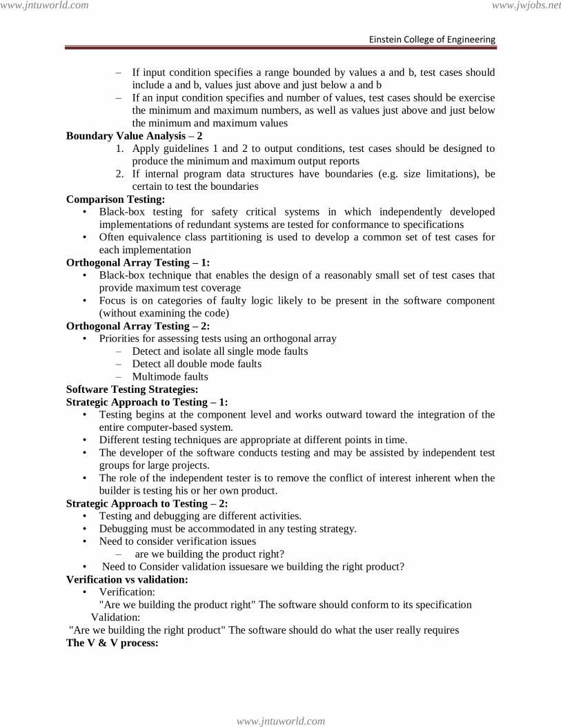
Einstein College of Engineering
– If input condition specifies a range bounded by values a and b, test cases should
include a and b, values just above and just below a and b
– If an input condition specifies and number of values, test cases should be exercise
the minimum and maximum numbers, as well as values just above and just below
the minimum and maximum values
Boundary Value Analysis – 2
1. Apply guidelines 1 and 2 to output conditions, test cases should be designed to
produce the minimum and maximum output reports
2. If internal program data structures have boundaries (e.g. size limitations), be
certain to test the boundaries
Comparison Testing:
• Black-box testing for safety critical systems in which independently developed
implementations of redundant systems are tested for conformance to specifications
• Often equivalence class partitioning is used to develop a common set of test cases for
each implementation
Orthogonal Array Testing – 1:
• Black-box technique that enables the design of a reasonably small set of test cases that
provide maximum test coverage
• Focus is on categories of faulty logic likely to be present in the software component
(without examining the code)
Orthogonal Array Testing – 2:
• Priorities for assessing tests using an orthogonal array
– Detect and isolate all single mode faults
– Detect all double mode faults
– Multimode faults
Software Testing Strategies:
Strategic Approach to Testing – 1:
• Testing begins at the component level and works outward toward the integration of the
entire computer-based system.
• Different testing techniques are appropriate at different points in time.
• The developer of the software conducts testing and may be assisted by independent test
groups for large projects.
• The role of the independent tester is to remove the conflict of interest inherent when the
builder is testing his or her own product.
Strategic Approach to Testing – 2:
• Testing and debugging are different activities.
• Debugging must be accommodated in any testing strategy.
• Need to consider verification issues
– are we building the product right?
• Need to Consider validation issuesare we building the right product?
Verification vs validation:
• Verification:
"Are we building the product right" The software should conform to its specification
Validation:
"Are we building the right product" The software should do what the user really requires
The V & V process:
www.jntuworld.com
www.jntuworld.com
www.jwjobs.net

Einstein College of Engineering
• As a whole life-cycle process - V & V must be applied at each stage in the software
process.
• Has two principal objectives
– The discovery of defects in a system
– The assessment of whether or not the system is usable in an operational situation.
• Strategic Testing Issues - 1 Specify product requirements in a quantifiable manner before
testing starts.
• Specify testing objectives explicitly.
• Identify the user classes of the software and develop a profile for each.
• Develop a test plan that emphasizes rapid cycle testing.
Strategic Testing Issues – 2:
• Build robust software that is designed to test itself (e.g. use anti-bugging).
• Use effective formal reviews as a filter prior to testing.
• Conduct formal technical reviews to assess the test strategy and test cases.
Testing Strategy:
Unit Testing:
www.jntuworld.com
www.jntuworld.com
www.jwjobs.net
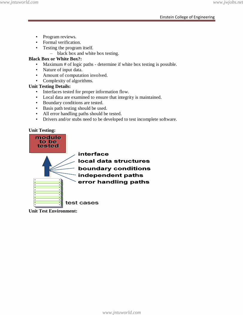
Einstein College of Engineering
• Program reviews.
• Formal verification.
• Testing the program itself.
– black box and white box testing.
Black Box or White Box?:
• Maximum # of logic paths - determine if white box testing is possible.
• Nature of input data.
• Amount of computation involved.
• Complexity of algorithms.
Unit Testing Details:
• Interfaces tested for proper information flow.
• Local data are examined to ensure that integrity is maintained.
• Boundary conditions are tested.
• Basis path testing should be used.
• All error handling paths should be tested.
• Drivers and/or stubs need to be developed to test incomplete software.
Unit Testing:
Unit Test Environment:
www.jntuworld.com
www.jntuworld.com
www.jwjobs.net
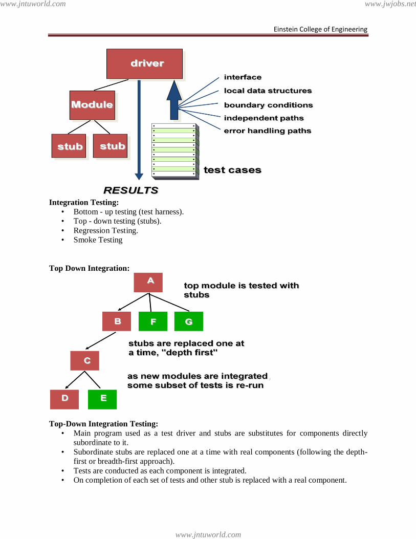
Einstein College of Engineering
Integration Testing:
• Bottom - up testing (test harness).
• Top - down testing (stubs).
• Regression Testing.
• Smoke Testing
Top Down Integration:
Top-Down Integration Testing:
• Main program used as a test driver and stubs are substitutes for components directly
subordinate to it.
• Subordinate stubs are replaced one at a time with real components (following the depth-
first or breadth-first approach).
• Tests are conducted as each component is integrated.
• On completion of each set of tests and other stub is replaced with a real component.
www.jntuworld.com
www.jntuworld.com
www.jwjobs.net
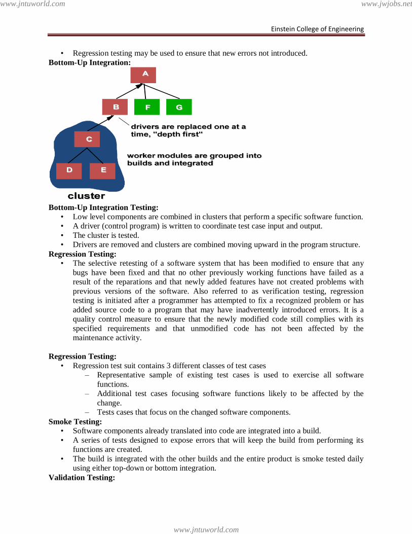
Einstein College of Engineering
• Regression testing may be used to ensure that new errors not introduced.
Bottom-Up Integration:
Bottom-Up Integration Testing:
• Low level components are combined in clusters that perform a specific software function.
• A driver (control program) is written to coordinate test case input and output.
• The cluster is tested.
• Drivers are removed and clusters are combined moving upward in the program structure.
Regression Testing:
• The selective retesting of a software system that has been modified to ensure that any
bugs have been fixed and that no other previously working functions have failed as a
result of the reparations and that newly added features have not created problems with
previous versions of the software. Also referred to as verification testing, regression
testing is initiated after a programmer has attempted to fix a recognized problem or has
added source code to a program that may have inadvertently introduced errors. It is a
quality control measure to ensure that the newly modified code still complies with its
specified requirements and that unmodified code has not been affected by the
maintenance activity.
Regression Testing:
• Regression test suit contains 3 different classes of test cases
– Representative sample of existing test cases is used to exercise all software
functions.
– Additional test cases focusing software functions likely to be affected by the
change.
– Tests cases that focus on the changed software components.
Smoke Testing:
• Software components already translated into code are integrated into a build.
• A series of tests designed to expose errors that will keep the build from performing its
functions are created.
• The build is integrated with the other builds and the entire product is smoke tested daily
using either top-down or bottom integration.
Validation Testing:
www.jntuworld.com
www.jntuworld.com
www.jwjobs.net
Einstein College of Engineering
• Ensure that each function or performance characteristic conforms to its specification.
• Deviations (deficiencies) must be negotiated with the customer to establish a means for
resolving the errors.
• Configuration review or audit is used to ensure that all elements of the software
configuration have been properly developed, cataloged, and documented to allow its
support during its maintenance phase.
Acceptance Testing:
• Making sure the software works correctly for intended user in his or her normal work
environment.
• Alpha test
– version of the complete software is tested by customer under the supervision of
the developer at the developer‘s site
• Beta test
– version of the complete software is tested by customer at his or her own site
without the developer being present
System Testing:
• Recovery testing
– checks system‘s ability to recover from failures
• Security testing
– verifies that system protection mechanism prevents improper penetration or data
alteration
• Stress testing
– program is checked to see how well it deals with abnormal resource demands
• Performance testing
– tests the run-time performance of software
Performance Testing:
• Stress test.
• Volume test.
• Configuration test (hardware & software).
• Compatibility.
• Regression tests.
• Security tests.
• Timing tests.
• Environmental tests.
• Quality tests.
• Recovery tests.
• Maintenance tests.
• Documentation tests.
• Human factors tests.
Testing Life Cycle:
• Establish test objectives.
• Design criteria (review criteria).
– Correct.
– Feasible.
– Coverage.
– Demonstrate functionality.
www.jntuworld.com
www.jntuworld.com
www.jwjobs.net
Einstein College of Engineering
• Writing test cases.
• Testing test cases.
• Execute test cases.
• Evaluate test results.
Testing Tools:
• Simulators.
• Monitors.
• Analyzers.
• Test data generators.
Document Each Test Case:
• Requirement tested.
• Facet / feature / path tested.
• Person & date.
• Tools & code needed.
• Test data & instructions.
• Expected results.
• Actual test results & analysis
• Correction, schedule, and signoff.
Debugging:
• Debugging (removal of a defect) occurs as a consequence of successful testing.
• Some people better at debugging than others.
• Is the cause of the bug reproduced in another part of the program?
• What ―next bug‖ might be introduced by the fix that is being proposed?
• What could have been done to prevent this bug in the first place?
Software Implementation techniques
Implementation techniques include imperative languages (object-oriented or procedural),
functional languages, and logic languages.
Software Implementation Techniques include process and thread scheduling, synchronization
and concurrency primitives, file management, memory management, performance,
networking facilities, and user interfaces. Software Implementation Techniques is designed
to facilitate determining what is required to implement a specific operating system function.
Procedural programming
Procedural programming can sometimes be used as a synonym for imperative
programming (specifying the steps the program must take to reach the desired state), but can also
refer (as in this article) to a programming paradigm, derived from structured programming, based
upon the concept of the procedure call. Procedures, also known as routines, subroutines,
methods, or functions (not to be confused with mathematical functions, but similar to those used
in functional programming) simply contain a series of computational steps to be carried out. Any
given procedure might be called at any point during a program's execution, including by other
procedures or itself. Some good examples of procedural programs are the Linux Kernel, GIT,
Apache Server, and Quake III Arena.
Object-oriented programming
www.jntuworld.com
www.jntuworld.com
www.jwjobs.net
Einstein College of Engineering
Object-oriented programming (OOP) is a programming paradigm that uses "objects" –
data structures consisting of data fields and methods together with their interactions – to design
applications and computer programs. Programming techniques may include features such as data
abstraction, encapsulation, modularity, polymorphism, and inheritance. Many modern
programming languages now support OOP.
An object-oriented program may thus be viewed as a collection of interacting objects, as
opposed to the conventional model, in which a program is seen as a list of tasks (subroutines) to
perform. In OOP, each object is capable of receiving messages, processing data, and sending
messages to other objects. Each object can be viewed as an independent 'machine' with a distinct
role or responsibility. The actions (or "methods") on these objects are closely associated with the
object. For example, OOP data structures tend to 'carry their own operators around with them' (or
at least "inherit" them from a similar object or class). In the conventional model, the data and
operations on the data don't have a tight, formal association.
functional programming is a programming paradigm that treats computation as the evaluation
of mathematical functions and avoids state and mutable data. It emphasizes the application of
functions, in contrast to the imperative programming style, which emphasizes changes in state.
Functional programming has its roots in lambda calculus, a formal system developed in the
1930s to investigate function definition, function application, and recursion. Many functional
programming languages can be viewed as elaborations on the lambda calculus.
In practice, the difference between a mathematical function and the notion of a "function"
used in imperative programming is that imperative functions can have side effects, changing the
value of already calculated computations. Because of this they lack referential transparency, i.e.
the same language expression can result in different values at different times depending on the
state of the executing program. Conversely, in functional code, the output value of a function
depends only on the arguments that are input to the function, so calling a function f twice with
the same value for an argument x will produce the same result f(x) both times. Eliminating side
effects can make it much easier to understand and predict the behavior of a program, which is
one of the key motivations for the development of functional programming.JavaScript, one of the
most widely employed languages today, incorporates functional programming capabilities.
Logic programming is, in its broadest sense, the use of mathematical logic for computer
programming. In this view of logic programming, which can be traced at least as far back as
John McCarthy's [1958] advice-taker proposal, logic is used as a purely declarative
representation language, and a theorem-prover or model-generator is used as the problem-solver.
The problem-solving task is split between the programmer, who is responsible only for ensuring
the truth of programs expressed in logical form, and the theorem-prover or model-generator,
which is responsible for solving problems efficiently.
Oracle’s Application Implementation Method
AIM provides with an integrated set of templates, procedures, PowerPoint presentations,
spreadsheets, and project plans for implementing the applications. AIM was such a success,
Oracle created a subset of the templates, called it AIM Advantage, and made it available as a
product to customers and other consulting firms. Since its initial release, AIM has been revised
and improved several times with new templates and methods.
www.jntuworld.com
www.jntuworld.com
www.jwjobs.net
Einstein College of Engineering
AIM Is a Six-Phase Method
Because the Oracle ERP Applications are software modules buy from a vendor, different
implementation methods are used than the techniques used for custom developed systems. AIM
has six major phases:
Definition phase: During this phase, you plan the project, determine business objectives,
and verify the feasibility of the project for given time, resource, and budget limits.
Operations Analysis phase: Includes documents business requirements, gaps in the
software (which can lead to customizations), and system architecture requirements. Results of
the analysis should provide a proposal for future business processes, a technical architecture
model, an application architecture model, workarounds for application gaps, performance testing
models, and a transition strategy to migrate to the new systems. Another task that can begin in
this phase is mapping of legacy data to Oracle Application APIs or open interfaces—data
conversion.
Solution Design phase—Used to create designs for solutions that meet future
business requirements and processes. The design of your future organization comes alive during
this phase as customizations and module configurations are finalized.
Build phase—During this phase of AIM, coding and testing of customizations,
enhancements, interfaces, and data conversions happens. In addition, one or more conference
room pilots test the integrated enterprise system. The results of the build phase should be a
working, tested business system solution.
Transition phase—During this phase, the project team delivers the finished
solution to the enterprise. End-user training and support, management of change, and data
conversions are major activities of this phase.
Production phase—Starts when the system goes live. Technical people work to
stabilize and maintain the system under full transaction loads. Users and the implementation
team begin a series of refinements to minimize unfavorable impacts and realize the business
objectives identified in the definition phase.
Rapid Implementations
In the late 1990s as Y2K approached, customers demanded and consulting firms discovered
faster ways to implement packaged software applications. The rapid implementation became
possible for certain types of customers. The events that converged in the late 1990s to provide
faster implementations include the following:
Many smaller companies couldn‘t afford the big ERP project. If the software vendors and
consulting firms were going to sell to the ―middle market‖ companies, they had to develop
more efficient methods.
Many dotcoms needed a financial infrastructure; ERP applications filled the need, and rapid
implementation methods provided the way.
The functionality of the software improved a lot, many gaps were eliminated, and more
companies could implement with fewer customizations.
After the big, complex companies implemented their ERP systems, the typical
implementation became less difficult.
The number of skilled consultants and project managers increased significantly.
Other software vendors started packaging preprogrammed integration points to the Oracle
ERP modules.
www.jntuworld.com
www.jntuworld.com
www.jwjobs.net
Einstein College of Engineering
Rapid implementations focus on delivering a predefined set of functionality. A key set of
business processes is installed in a standard way to accelerate the implementation schedule.
These projects benefit from the use of preconfigured modules and predefined business processes.
You get to reuse the analysis and integration testing from other implementations, and you agree
to ignore all gaps by modifying your business to fit the software. Typically, the enterprise will be
allowed some control over key decisions such as the structure of the chart of accounts. Fixed
budgets are set for training, production support, and data conversions (a limited amount of data).
Phased Implementations
Phased implementations seek to break up the work of an ERP implementation project.
This technique can make the system more manageable and reduce risks, and costs in some cases,
to the enterprise. In the mid-1990s, 4 or 5 was about the maximum number of application
modules that could be launched into production at one time. If you bought 12 or 13 applications,
there would be a financial phase that would be followed by phases for the distribution and
manufacturing applications. As implementation techniques improved and Y2K pressures grew in
the late 1990s, more and more companies started launching most of their applications at the same
time. This method became known as the big-bang approach. Now, each company selects a
phased or big-bang approach based on its individual requirements.
Another approach to phasing can be employed by companies with business units at
multiple sites. With this technique, one business unit is used as a template, and all applications
are completely implemented in an initial phase lasting 10–14 months. Then, other sites
implement the applications in cookie-cutter fashion. The cookie-cutter phases are focused on
end-user training and the differences that a site has from the prototype site. The cookie-cutter
phase can be as short as 9–12 weeks, and these phases can be conducted at several sites
simultaneously. For your reference, we participated in an efficient project where 13 applications
were implemented big bang–style in July at the Chicago site after about 8 months work. A site in
Malaysia went live in October. The Ireland site started up in November. After a holiday break,
the Atlanta business unit went live in February, and the final site in China started using the
applications in April. Implementing thirteen application modules at five sites in four countries in
sixteen months was pretty impressive.
Case Studies Illustrating Implementation Techniques
Some practical examples from the real world might help to illustrate some of the principles and
techniques of various software implementation methods. These case studies are composites from
about 60 implementation projects we have observed during the past 9 years.
Big companies often have a horrible time resolving issues and deciding on configuration
parameters because there is so much money involved and each of many sites might want to
control decisions about what it considers its critical success factors. For example, we once saw a
large company argue for over two months about the chart of accounts structure, while eight
consultants from two consulting firms tried to referee among the feuding operating units.
Another large company labored for more than six months to unify a master customer list for a
centralized receivables and decentralized order entry system.
Transition activities at large companies need special attention. Training end users can be
a logistical challenge and can require considerable planning. For example, if you have 800 users
to train and each user needs an average of three classes of two hours each and you have one
month, how many classrooms and instructors do you need? Another example is that loading data
www.jntuworld.com
www.jntuworld.com
www.jwjobs.net
Einstein College of Engineering
from a legacy system can be a problem. If you have one million customers to load into Oracle
receivables at the rate of 5,000/hour and the database administrator allows you to load 20 hours
per day, you have a 10-day task.
Because they spend huge amounts of money on their ERP systems, many big companies
try to optimize the systems and capture specific returns on the investment. However, sometimes
companies can be incredibly insensitive and uncoordinated as they try to make money from their
ERP software. For example, one business announced at the beginning of a project that the
accounts payable department would be cut from 50–17 employees as soon as the system went
live. Another company decided to centralize about 30 accounting sites into one shared service
center and advised about 60 accountants that they would lose their jobs in about a year. Several
of the 60 employees were offered positions on the ERP implementation team.
Small companies have other problems when creating an implementation team. Occasionally, the
small company tries to put clerical employees on the team and they have problems with issue
resolution or some of the ERP concepts. In another case, one small company didn‘t create the
position of project manager. Each department worked on its own modules and ignored the
integration points, testing, and requirements of other users. When Y2K deadlines forced the
system startup, results were disastrous with a cost impact that doubled the cost of the entire
project.
Project team members at small companies sometimes have a hard time relating to the cost
of the implementation. We once worked with a company where the project manager (who was
also the database administrator) advised me within the first hour of our meeting that he thought
consulting charges of $3/minute were outrageous, and he couldn‘t rationalize how we could
possibly make such a contribution. We agreed a consultant could not contribute $3 in value each
and every minute to his project. However, when I told him we would be able to save him
$10,000/week and make the difference between success and failure, he realized we should get to
work.
Because the small company might be relatively simple to implement and the technical
staff might be inexperienced with the database and software, it is possible that the technical staff
will be on the critical path of the project. If the database administrator can‘t learn how to handle
the production database by the time the users are ready to go live, you might need to hire some
temporary help to enable the users to keep to the schedule. In addition, we often see small
companies with just a single database administrator who might be working 60 or more hours per
week. They feel they can afford to have more DBAs as employees, but they don‘t know how to
establish the right ratio of support staff to user requirements. These companies can burn out a
DBA quickly and then have to deal with the problem of replacing an important skill.
www.jntuworld.com
www.jntuworld.com
www.jwjobs.net
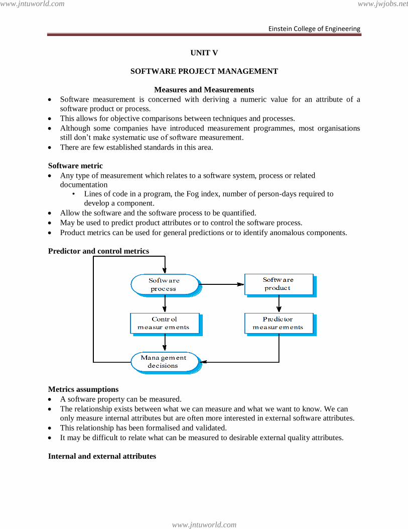
Einstein College of Engineering
UNIT V
SOFTWARE PROJECT MANAGEMENT
Measures and Measurements
Software measurement is concerned with deriving a numeric value for an attribute of a
software product or process.
This allows for objective comparisons between techniques and processes.
Although some companies have introduced measurement programmes, most organisations
still don‘t make systematic use of software measurement.
There are few established standards in this area.
Software metric
Any type of measurement which relates to a software system, process or related
documentation
• Lines of code in a program, the Fog index, number of person-days required to
develop a component.
Allow the software and the software process to be quantified.
May be used to predict product attributes or to control the software process.
Product metrics can be used for general predictions or to identify anomalous components.
Predictor and control metrics
Metrics assumptions
A software property can be measured.
The relationship exists between what we can measure and what we want to know. We can
only measure internal attributes but are often more interested in external software attributes.
This relationship has been formalised and validated.
It may be difficult to relate what can be measured to desirable external quality attributes.
Internal and external attributes
www.jntuworld.com
www.jntuworld.com
www.jwjobs.net
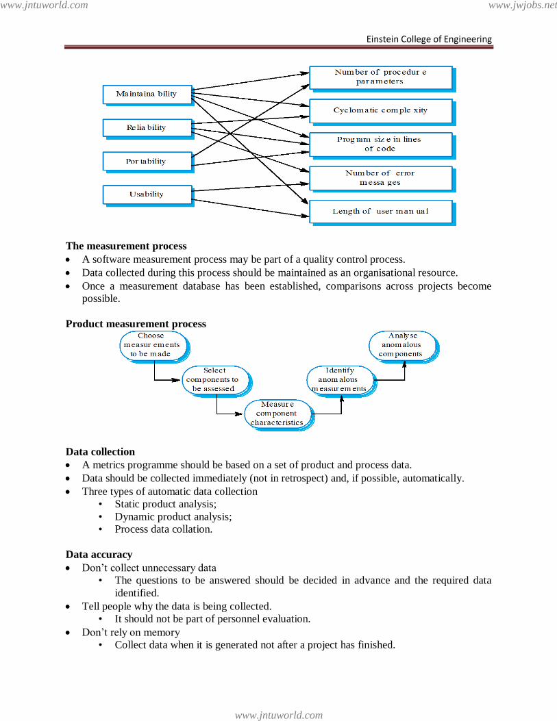
Einstein College of Engineering
The measurement process
A software measurement process may be part of a quality control process.
Data collected during this process should be maintained as an organisational resource.
Once a measurement database has been established, comparisons across projects become
possible.
Product measurement process
Data collection
A metrics programme should be based on a set of product and process data.
Data should be collected immediately (not in retrospect) and, if possible, automatically.
Three types of automatic data collection
• Static product analysis;
• Dynamic product analysis;
• Process data collation.
Data accuracy
Don‘t collect unnecessary data
• The questions to be answered should be decided in advance and the required data
identified.
Tell people why the data is being collected.
• It should not be part of personnel evaluation.
Don‘t rely on memory
• Collect data when it is generated not after a project has finished.
www.jntuworld.com
www.jntuworld.com
www.jwjobs.net
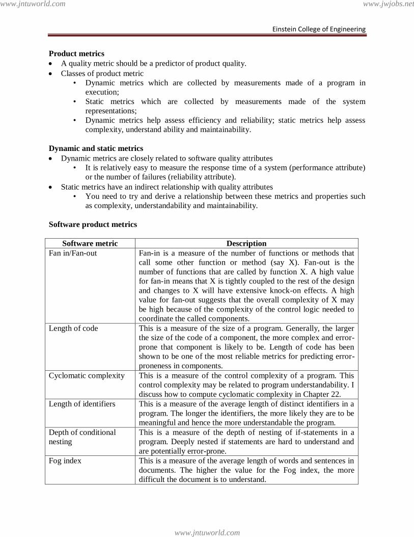
Einstein College of Engineering
Product metrics
A quality metric should be a predictor of product quality.
Classes of product metric
• Dynamic metrics which are collected by measurements made of a program in
execution;
• Static metrics which are collected by measurements made of the system
representations;
• Dynamic metrics help assess efficiency and reliability; static metrics help assess
complexity, understand ability and maintainability.
Dynamic and static metrics
Dynamic metrics are closely related to software quality attributes
• It is relatively easy to measure the response time of a system (performance attribute)
or the number of failures (reliability attribute).
Static metrics have an indirect relationship with quality attributes
• You need to try and derive a relationship between these metrics and properties such
as complexity, understandability and maintainability.
Software product metrics
Software metric Description
Fan in/Fan-out Fan-in is a measure of the number of functions or methods that
call some other function or method (say X). Fan-out is the
number of functions that are called by function X. A high value
for fan-in means that X is tightly coupled to the rest of the design
and changes to X will have extensive knock-on effects. A high
value for fan-out suggests that the overall complexity of X may
be high because of the complexity of the control logic needed to
coordinate the called components.
Length of code This is a measure of the size of a program. Generally, the larger
the size of the code of a component, the more complex and error-
prone that component is likely to be. Length of code has been
shown to be one of the most reliable metrics for predicting error-
proneness in components.
Cyclomatic complexity This is a measure of the control complexity of a program. This
control complexity may be related to program understandability. I
discuss how to compute cyclomatic complexity in Chapter 22.
Length of identifiers This is a measure of the average length of distinct identifiers in a
program. The longer the identifiers, the more likely they are to be
meaningful and hence the more understandable the program.
Depth of conditional
nesting
This is a measure of the depth of nesting of if-statements in a
program. Deeply nested if statements are hard to understand and
are potentially error-prone.
Fog index This is a measure of the average length of words and sentences in
documents. The higher the value for the Fog index, the more
difficult the document is to understand.
www.jntuworld.com
www.jntuworld.com
www.jwjobs.net
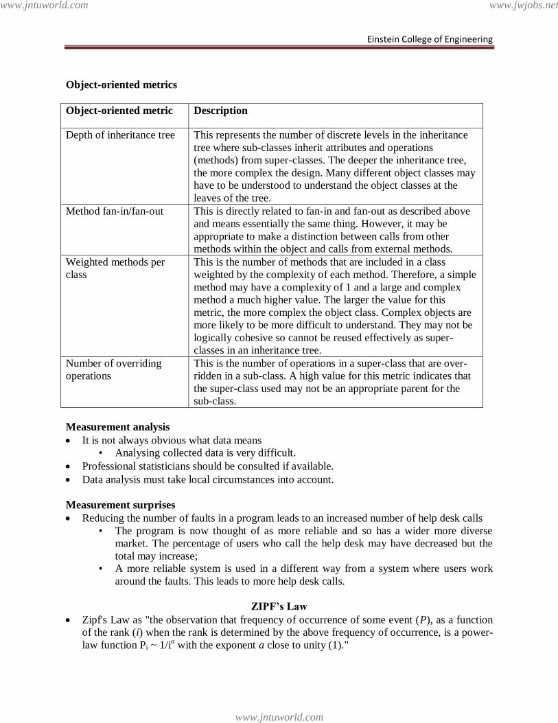
Einstein College of Engineering
Object-oriented metrics
Object-oriented metric Description
Depth of inheritance tree This represents the number of discrete levels in the inheritance
tree where sub-classes inherit attributes and operations
(methods) from super-classes. The deeper the inheritance tree,
the more complex the design. Many different object classes may
have to be understood to understand the object classes at the
leaves of the tree.
Method fan-in/fan-out This is directly related to fan-in and fan-out as described above
and means essentially the same thing. However, it may be
appropriate to make a distinction between calls from other
methods within the object and calls from external methods.
Weighted methods per
class
This is the number of methods that are included in a class
weighted by the complexity of each method. Therefore, a simple
method may have a complexity of 1 and a large and complex
method a much higher value. The larger the value for this
metric, the more complex the object class. Complex objects are
more likely to be more difficult to understand. They may not be
logically cohesive so cannot be reused effectively as super-
classes in an inheritance tree.
Number of overriding
operations
This is the number of operations in a super-class that are over-
ridden in a sub-class. A high value for this metric indicates that
the super-class used may not be an appropriate parent for the
sub-class.
Measurement analysis
It is not always obvious what data means
• Analysing collected data is very difficult.
Professional statisticians should be consulted if available.
Data analysis must take local circumstances into account.
Measurement surprises
Reducing the number of faults in a program leads to an increased number of help desk calls
• The program is now thought of as more reliable and so has a wider more diverse
market. The percentage of users who call the help desk may have decreased but the
total may increase;
• A more reliable system is used in a different way from a system where users work
around the faults. This leads to more help desk calls.
ZIPF’s Law
Zipf's Law as "the observation that frequency of occurrence of some event (P), as a function
of the rank (i) when the rank is determined by the above frequency of occurrence, is a power-
law function Pi ~ 1/ia with the exponent a close to unity (1)."
www.jntuworld.com
www.jntuworld.com
www.jwjobs.net
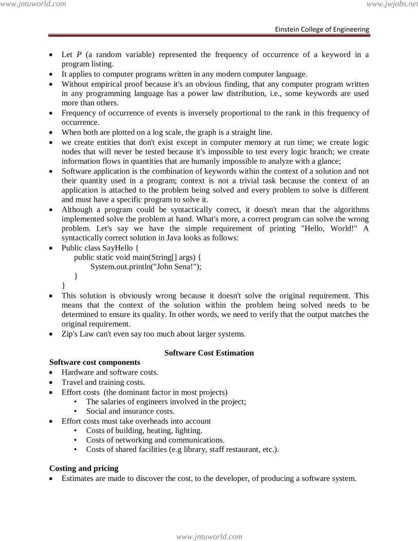
Einstein College of Engineering
Let P (a random variable) represented the frequency of occurrence of a keyword in a
program listing.
It applies to computer programs written in any modern computer language.
Without empirical proof because it's an obvious finding, that any computer program written
in any programming language has a power law distribution, i.e., some keywords are used
more than others.
Frequency of occurrence of events is inversely proportional to the rank in this frequency of
occurrence.
When both are plotted on a log scale, the graph is a straight line.
we create entities that don't exist except in computer memory at run time; we create logic
nodes that will never be tested because it's impossible to test every logic branch; we create
information flows in quantities that are humanly impossible to analyze with a glance;
Software application is the combination of keywords within the context of a solution and not
their quantity used in a program; context is not a trivial task because the context of an
application is attached to the problem being solved and every problem to solve is different
and must have a specific program to solve it.
Although a program could be syntactically correct, it doesn't mean that the algorithms
implemented solve the problem at hand. What's more, a correct program can solve the wrong
problem. Let's say we have the simple requirement of printing "Hello, World!" A
syntactically correct solution in Java looks as follows:
Public class SayHello {
public static void main(String[] args) {
System.out.println("John Sena!");
}
}
This solution is obviously wrong because it doesn't solve the original requirement. This
means that the context of the solution within the problem being solved needs to be
determined to ensure its quality. In other words, we need to verify that the output matches the
original requirement.
Zip's Law can't even say too much about larger systems.
Software Cost Estimation
Software cost components
Hardware and software costs.
Travel and training costs.
Effort costs (the dominant factor in most projects)
• The salaries of engineers involved in the project;
• Social and insurance costs.
Effort costs must take overheads into account
• Costs of building, heating, lighting.
• Costs of networking and communications.
• Costs of shared facilities (e.g library, staff restaurant, etc.).
Costing and pricing
Estimates are made to discover the cost, to the developer, of producing a software system.
www.jntuworld.com
www.jntuworld.com
www.jwjobs.net
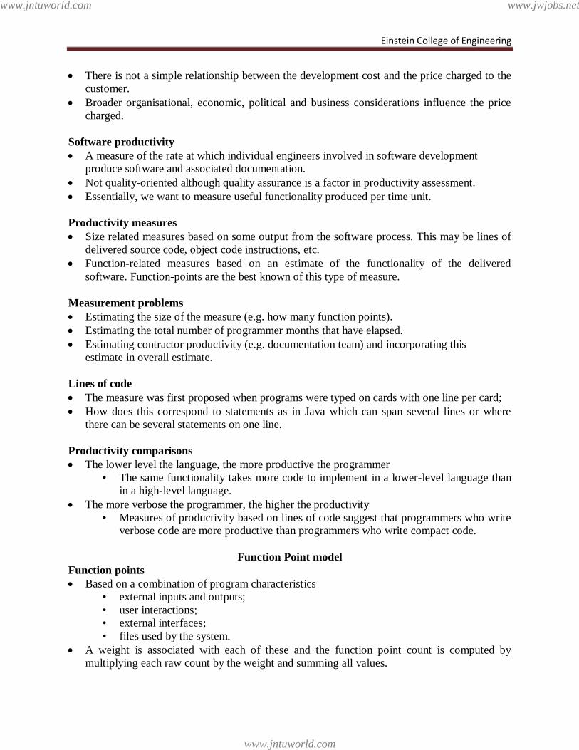
Einstein College of Engineering
There is not a simple relationship between the development cost and the price charged to the
customer.
Broader organisational, economic, political and business considerations influence the price
charged.
Software productivity
A measure of the rate at which individual engineers involved in software development
produce software and associated documentation.
Not quality-oriented although quality assurance is a factor in productivity assessment.
Essentially, we want to measure useful functionality produced per time unit.
Productivity measures
Size related measures based on some output from the software process. This may be lines of
delivered source code, object code instructions, etc.
Function-related measures based on an estimate of the functionality of the delivered
software. Function-points are the best known of this type of measure.
Measurement problems
Estimating the size of the measure (e.g. how many function points).
Estimating the total number of programmer months that have elapsed.
Estimating contractor productivity (e.g. documentation team) and incorporating this
estimate in overall estimate.
Lines of code
The measure was first proposed when programs were typed on cards with one line per card;
How does this correspond to statements as in Java which can span several lines or where
there can be several statements on one line.
Productivity comparisons
The lower level the language, the more productive the programmer
• The same functionality takes more code to implement in a lower-level language than
in a high-level language.
The more verbose the programmer, the higher the productivity
• Measures of productivity based on lines of code suggest that programmers who write
verbose code are more productive than programmers who write compact code.
Function Point model
Function points
Based on a combination of program characteristics
• external inputs and outputs;
• user interactions;
• external interfaces;
• files used by the system.
A weight is associated with each of these and the function point count is computed by
multiplying each raw count by the weight and summing all values.
www.jntuworld.com
www.jntuworld.com
www.jwjobs.net
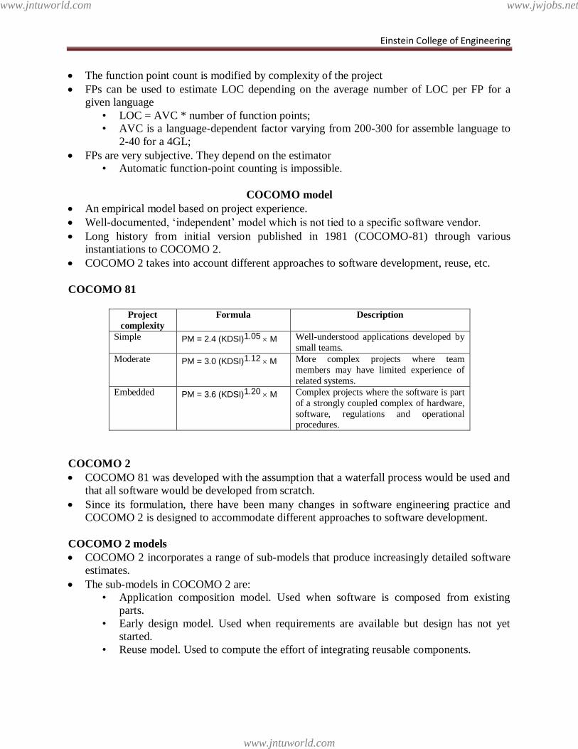
Einstein College of Engineering
The function point count is modified by complexity of the project
FPs can be used to estimate LOC depending on the average number of LOC per FP for a
given language
• LOC = AVC * number of function points;
• AVC is a language-dependent factor varying from 200-300 for assemble language to
2-40 for a 4GL;
FPs are very subjective. They depend on the estimator
• Automatic function-point counting is impossible.
COCOMO model
An empirical model based on project experience.
Well-documented, ‗independent‘ model which is not tied to a specific software vendor.
Long history from initial version published in 1981 (COCOMO-81) through various
instantiations to COCOMO 2.
COCOMO 2 takes into account different approaches to software development, reuse, etc.
COCOMO 81
Project
complexity
Formula Description
Simple PM = 2.4 (KDSI)1.05 M Well-understood applications developed by
small teams.
Moderate PM = 3.0 (KDSI)1.12 M More complex projects where team
members may have limited experience of
related systems.
Embedded PM = 3.6 (KDSI)1.20 M Complex projects where the software is part
of a strongly coupled complex of hardware,
software, regulations and operational procedures.
COCOMO 2
COCOMO 81 was developed with the assumption that a waterfall process would be used and
that all software would be developed from scratch.
Since its formulation, there have been many changes in software engineering practice and
COCOMO 2 is designed to accommodate different approaches to software development.
COCOMO 2 models
COCOMO 2 incorporates a range of sub-models that produce increasingly detailed software
estimates.
The sub-models in COCOMO 2 are:
• Application composition model. Used when software is composed from existing
parts.
• Early design model. Used when requirements are available but design has not yet
started.
• Reuse model. Used to compute the effort of integrating reusable components.
www.jntuworld.com
www.jntuworld.com
www.jwjobs.net
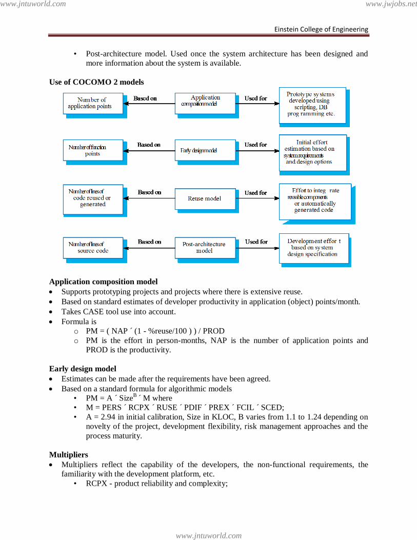
Einstein College of Engineering
• Post-architecture model. Used once the system architecture has been designed and
more information about the system is available.
Use of COCOMO 2 models
Application composition model
Supports prototyping projects and projects where there is extensive reuse.
Based on standard estimates of developer productivity in application (object) points/month.
Takes CASE tool use into account.
Formula is
o PM = ( NAP ´ (1 - %reuse/100 ) ) / PROD
o PM is the effort in person-months, NAP is the number of application points and
PROD is the productivity.
Early design model
Estimates can be made after the requirements have been agreed.
Based on a standard formula for algorithmic models
• PM = A ´ SizeB
´ M where
• M = PERS ´ RCPX ´ RUSE ´ PDIF ´ PREX ´ FCIL ´ SCED;
• A = 2.94 in initial calibration, Size in KLOC, B varies from 1.1 to 1.24 depending on
novelty of the project, development flexibility, risk management approaches and the
process maturity.
Multipliers
Multipliers reflect the capability of the developers, the non-functional requirements, the
familiarity with the development platform, etc.
• RCPX - product reliability and complexity;
www.jntuworld.com
www.jntuworld.com
www.jwjobs.net
Einstein College of Engineering
• RUSE - the reuse required;
• PDIF - platform difficulty;
• PREX - personnel experience;
• PERS - personnel capability;
• SCED - required schedule;
• FCIL - the team support facilities.
The reuse model
Takes into account black-box code that is reused without change and code that has to be
adapted to integrate it with new code.
There are two versions:
• Black-box reuse where code is not modified. An effort estimate (PM) is computed.
• White-box reuse where code is modified. A size estimate equivalent to the number of
lines of new source code is computed. This then adjusts the size estimate for new
code.
Reuse model estimates
For generated code:
• PM = (ASLOC * AT/100)/ATPROD
• ASLOC is the number of lines of generated code
• AT is the percentage of code automatically generated.
• ATPROD is the productivity of engineers in integrating this code.
When code has to be understood and integrated:
• ESLOC = ASLOC * (1-AT/100) * AAM.
• ASLOC and AT as before.
• AAM is the adaptation adjustment multiplier computed from the costs of changing
the reused code, the costs of understanding how to integrate the code and the costs of
reuse decision making.
Post-architecture level
Uses the same formula as the early design model but with 17 rather than 7 associated
multipliers.
The code size is estimated as:
• Number of lines of new code to be developed;
• Estimate of equivalent number of lines of new code computed using the reuse model;
• An estimate of the number of lines of code that have to be modified according to
requirements changes.
The exponent term
This depends on 5 scale factors (see next slide). Their sum/100 is added to 1.01
A company takes on a project in a new domain. The client has not defined the process to be
used and has not allowed time for risk analysis. The company has a CMM level 2 rating.
• Precedenteness - new project (4)
• Development flexibility - no client involvement - Very high (1)
• Architecture/risk resolution - No risk analysis - V. Low .(5)
• Team cohesion - new team - nominal (3)
• Process maturity - some control - nominal (3)
www.jntuworld.com
www.jntuworld.com
www.jwjobs.net
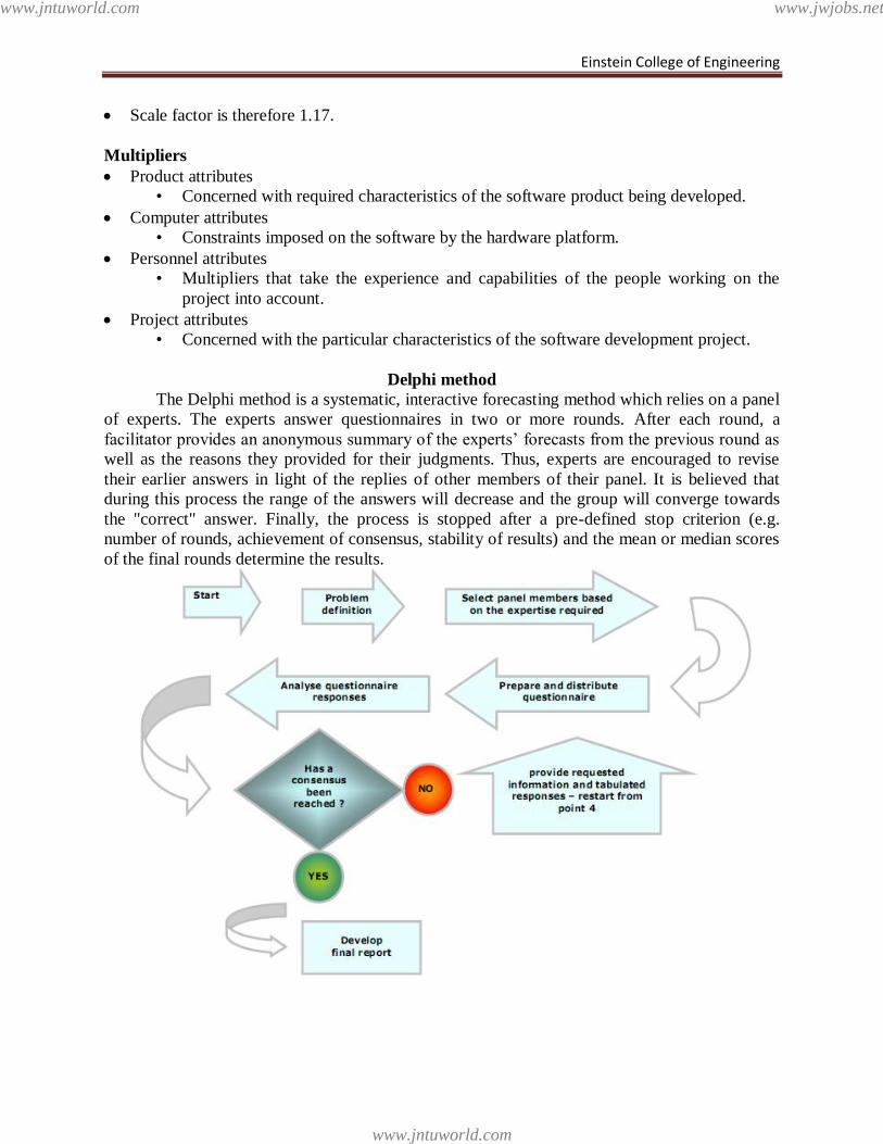
Einstein College of Engineering
Scale factor is therefore 1.17.
Multipliers
Product attributes
• Concerned with required characteristics of the software product being developed.
Computer attributes
• Constraints imposed on the software by the hardware platform.
Personnel attributes
• Multipliers that take the experience and capabilities of the people working on the
project into account.
Project attributes
• Concerned with the particular characteristics of the software development project.
Delphi method
The Delphi method is a systematic, interactive forecasting method which relies on a panel
of experts. The experts answer questionnaires in two or more rounds. After each round, a
facilitator provides an anonymous summary of the experts‘ forecasts from the previous round as
well as the reasons they provided for their judgments. Thus, experts are encouraged to revise
their earlier answers in light of the replies of other members of their panel. It is believed that
during this process the range of the answers will decrease and the group will converge towards
the "correct" answer. Finally, the process is stopped after a pre-defined stop criterion (e.g.
number of rounds, achievement of consensus, stability of results) and the mean or median scores
of the final rounds determine the results.
www.jntuworld.com
www.jntuworld.com
www.jwjobs.net
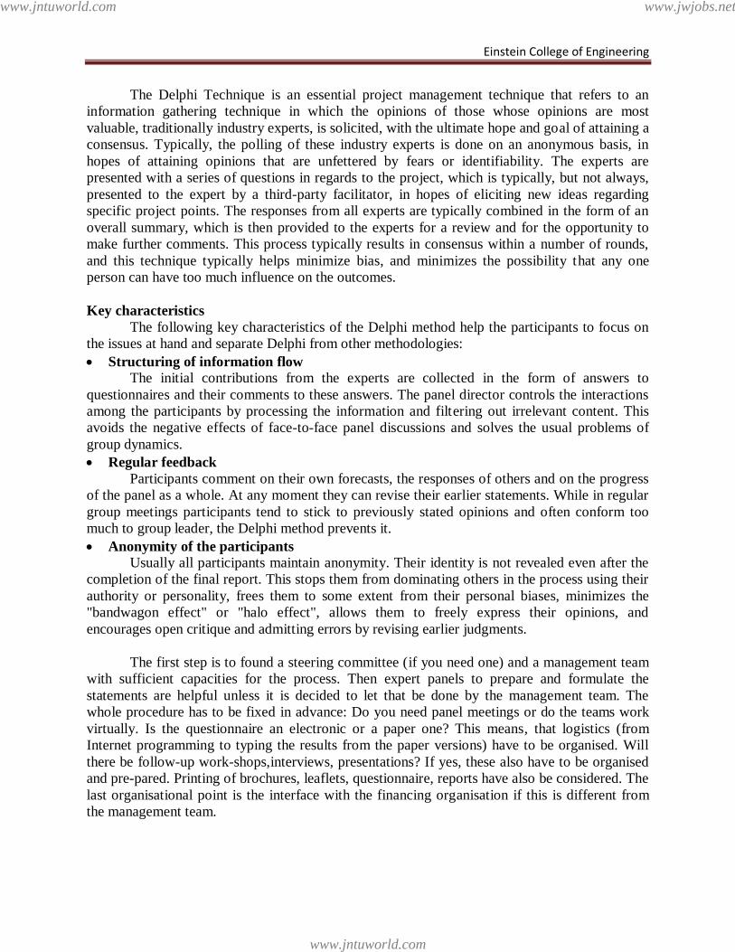
Einstein College of Engineering
The Delphi Technique is an essential project management technique that refers to an
information gathering technique in which the opinions of those whose opinions are most
valuable, traditionally industry experts, is solicited, with the ultimate hope and goal of attaining a
consensus. Typically, the polling of these industry experts is done on an anonymous basis, in
hopes of attaining opinions that are unfettered by fears or identifiability. The experts are
presented with a series of questions in regards to the project, which is typically, but not always,
presented to the expert by a third-party facilitator, in hopes of eliciting new ideas regarding
specific project points. The responses from all experts are typically combined in the form of an
overall summary, which is then provided to the experts for a review and for the opportunity to
make further comments. This process typically results in consensus within a number of rounds,
and this technique typically helps minimize bias, and minimizes the possibility that any one
person can have too much influence on the outcomes.
Key characteristics
The following key characteristics of the Delphi method help the participants to focus on
the issues at hand and separate Delphi from other methodologies:
Structuring of information flow
The initial contributions from the experts are collected in the form of answers to
questionnaires and their comments to these answers. The panel director controls the interactions
among the participants by processing the information and filtering out irrelevant content. This
avoids the negative effects of face-to-face panel discussions and solves the usual problems of
group dynamics.
Regular feedback
Participants comment on their own forecasts, the responses of others and on the progress
of the panel as a whole. At any moment they can revise their earlier statements. While in regular
group meetings participants tend to stick to previously stated opinions and often conform too
much to group leader, the Delphi method prevents it.
Anonymity of the participants
Usually all participants maintain anonymity. Their identity is not revealed even after the
completion of the final report. This stops them from dominating others in the process using their
authority or personality, frees them to some extent from their personal biases, minimizes the
"bandwagon effect" or "halo effect", allows them to freely express their opinions, and
encourages open critique and admitting errors by revising earlier judgments.
The first step is to found a steering committee (if you need one) and a management team
with sufficient capacities for the process. Then expert panels to prepare and formulate the
statements are helpful unless it is decided to let that be done by the management team. The
whole procedure has to be fixed in advance: Do you need panel meetings or do the teams work
virtually. Is the questionnaire an electronic or a paper one? This means, that logistics (from
Internet programming to typing the results from the paper versions) have to be organised. Will
there be follow-up work-shops,interviews, presentations? If yes, these also have to be organised
and pre-pared. Printing of brochures, leaflets, questionnaire, reports have also be considered. The
last organisational point is the interface with the financing organisation if this is different from
the management team.
www.jntuworld.com
www.jntuworld.com
www.jwjobs.net
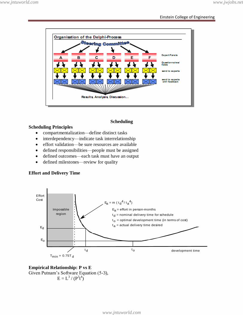
Einstein College of Engineering
Scheduling
Scheduling Principles
compartmentalization—define distinct tasks
interdependency—indicate task interrelationship
effort validation—be sure resources are available
defined responsibilities—people must be assigned
defined outcomes—each task must have an output
defined milestones—review for quality
Effort and Delivery Time
Empirical Relationship: P vs E
Given Putnam‘s Software Equation (5-3),
E = L3 / (P
3t4)
Effort
Cost
Impossible
region
td
Ed
Tmin = 0.75T d
to
Eo
Ea = m ( td4 / ta
4)
development time
Ea = effort in person-months
td = nominal delivery time for schedule
to = optimal development time (in terms of cost)
ta = actual delivery time desired
www.jntuworld.com
www.jntuworld.com
www.jwjobs.net
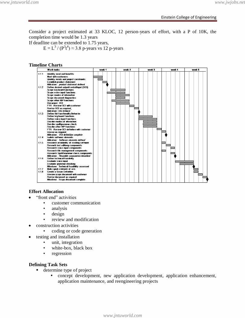
Einstein College of Engineering
Consider a project estimated at 33 KLOC, 12 person-years of effort, with a P of 10K, the
completion time would be 1.3 years
If deadline can be extended to 1.75 years,
E = L3 / (P
3t4) ≈ 3.8 p-years vs 12 p-years
Timeline Charts
Effort Allocation
―front end‖ activities
• customer communication
• analysis
• design
• review and modification
construction activities
• coding or code generation
testing and installation
• unit, integration
• white-box, black box
• regression
Defining Task Sets
determine type of project
concept development, new application development, application enhancement,
application maintenance, and reengineering projects
www.jntuworld.com
www.jntuworld.com
www.jwjobs.net
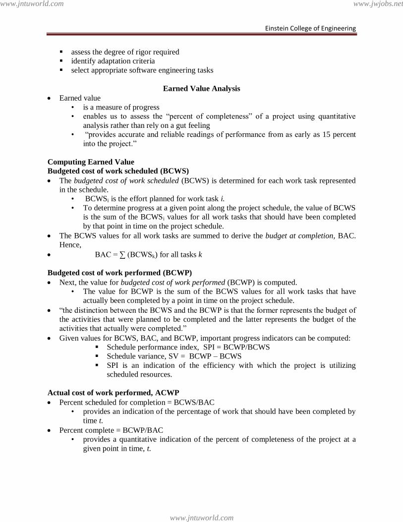
Einstein College of Engineering
assess the degree of rigor required
identify adaptation criteria
select appropriate software engineering tasks
Earned Value Analysis
Earned value
• is a measure of progress
• enables us to assess the ―percent of completeness‖ of a project using quantitative
analysis rather than rely on a gut feeling
• ―provides accurate and reliable readings of performance from as early as 15 percent
into the project.‖
Computing Earned Value
Budgeted cost of work scheduled (BCWS)
The budgeted cost of work scheduled (BCWS) is determined for each work task represented
in the schedule.
• BCWSi is the effort planned for work task i.
• To determine progress at a given point along the project schedule, the value of BCWS
is the sum of the BCWSi values for all work tasks that should have been completed
by that point in time on the project schedule.
The BCWS values for all work tasks are summed to derive the budget at completion, BAC.
Hence,
BAC = ∑ (BCWSk) for all tasks k
Budgeted cost of work performed (BCWP)
Next, the value for budgeted cost of work performed (BCWP) is computed.
• The value for BCWP is the sum of the BCWS values for all work tasks that have
actually been completed by a point in time on the project schedule.
―the distinction between the BCWS and the BCWP is that the former represents the budget of
the activities that were planned to be completed and the latter represents the budget of the
activities that actually were completed.‖
Given values for BCWS, BAC, and BCWP, important progress indicators can be computed:
Schedule performance index, SPI = BCWP/BCWS
Schedule variance, SV = BCWP – BCWS
SPI is an indication of the efficiency with which the project is utilizing
scheduled resources.
Actual cost of work performed, ACWP
Percent scheduled for completion = BCWS/BAC
• provides an indication of the percentage of work that should have been completed by
time t.
Percent complete = BCWP/BAC
• provides a quantitative indication of the percent of completeness of the project at a
given point in time, t.
www.jntuworld.com
www.jntuworld.com
www.jwjobs.net
Einstein College of Engineering
Actual cost of work performed, ACWP, is the sum of the effort actually expended on work
tasks that have been completed by a point in time on the project schedule. It is then possible
to compute
Cost performance index, CPI = BCWP/ACWP
Cost variance, CV = BCWP – ACWP
Problem
Assume you are a software project manager and that you‘ve been asked to computer earned
value statistics for a small software project. The project has 56 planned work tasks that are
estimated to require 582 person-days to complete. At the time that you‘ve been asked to do
the earned value analysis, 12 tasks have been completed. However, the project schedule
indicates that 15 tasks should have been completed. The following scheduling data (in
person-days) are available:
Task Planned Effort Actual Effort
1 12 12.5
2 15 11
3 13 17
4 8 9.5
5 9.5 9.0
6 18 19
7 10 10
8 4 4.5
9 12 10
10 6 6.5
11 5 4
12 14 14.5
13 16
14 6
15 8
Error Tracking
Schedule Tracking
• conduct periodic project status meetings in which each team member reports progress
and problems.
• evaluate the results of all reviews conducted throughout the software engineering
process.
• determine whether formal project milestones (diamonds in previous slide) have been
accomplished by the scheduled date.
• compare actual start-date to planned start-date for each project task listed in the
resource table
• meet informally with practitioners to obtain their subjective assessment of progress to
date and problems on the horizon.
• use earned value analysis to assess progress quantitatively.
Progress on an OO Project-I
www.jntuworld.com
www.jntuworld.com
www.jwjobs.net
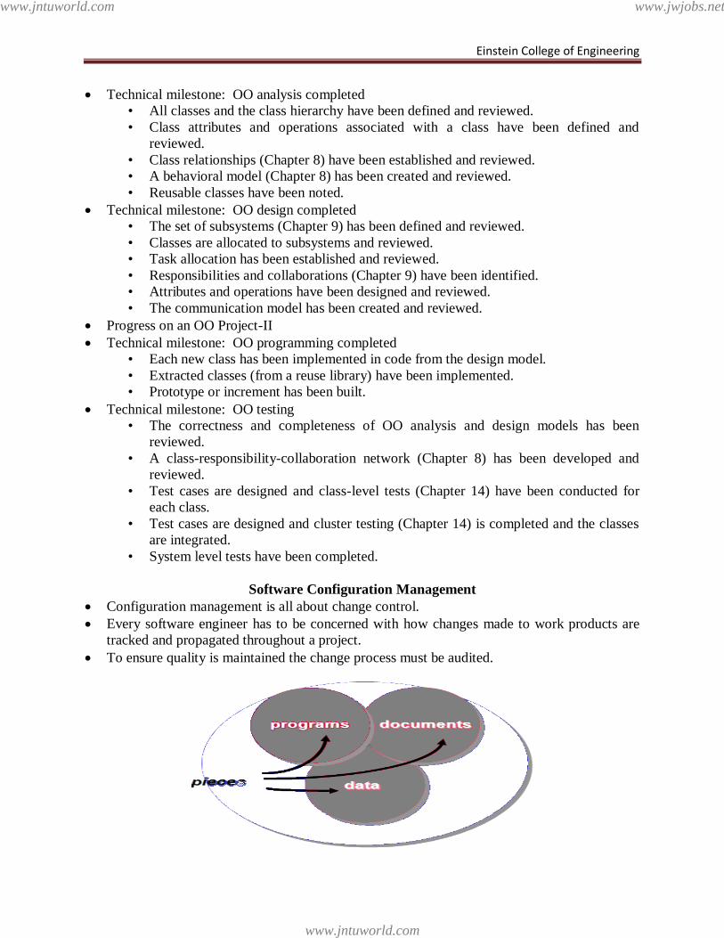
Einstein College of Engineering
Technical milestone: OO analysis completed
• All classes and the class hierarchy have been defined and reviewed.
• Class attributes and operations associated with a class have been defined and
reviewed.
• Class relationships (Chapter 8) have been established and reviewed.
• A behavioral model (Chapter 8) has been created and reviewed.
• Reusable classes have been noted.
Technical milestone: OO design completed
• The set of subsystems (Chapter 9) has been defined and reviewed.
• Classes are allocated to subsystems and reviewed.
• Task allocation has been established and reviewed.
• Responsibilities and collaborations (Chapter 9) have been identified.
• Attributes and operations have been designed and reviewed.
• The communication model has been created and reviewed.
Progress on an OO Project-II
Technical milestone: OO programming completed
• Each new class has been implemented in code from the design model.
• Extracted classes (from a reuse library) have been implemented.
• Prototype or increment has been built.
Technical milestone: OO testing
• The correctness and completeness of OO analysis and design models has been
reviewed.
• A class-responsibility-collaboration network (Chapter 8) has been developed and
reviewed.
• Test cases are designed and class-level tests (Chapter 14) have been conducted for
each class.
• Test cases are designed and cluster testing (Chapter 14) is completed and the classes
are integrated.
• System level tests have been completed.
Software Configuration Management
Configuration management is all about change control.
Every software engineer has to be concerned with how changes made to work products are
tracked and propagated throughout a project.
To ensure quality is maintained the change process must be audited.
www.jntuworld.com
www.jntuworld.com
www.jwjobs.net
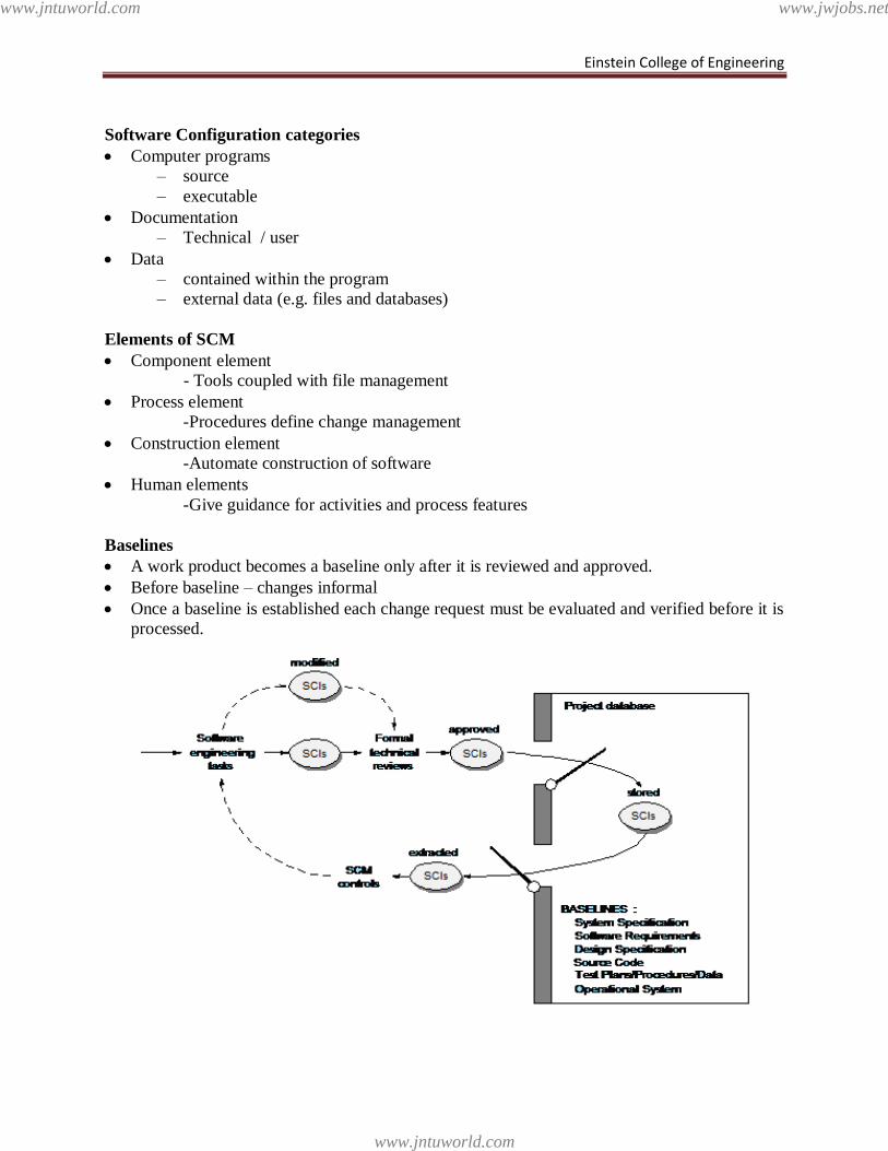
Einstein College of Engineering
Software Configuration categories
Computer programs
– source
– executable
Documentation
– Technical / user
Data
– contained within the program
– external data (e.g. files and databases)
Elements of SCM
Component element
- Tools coupled with file management
Process element
-Procedures define change management
Construction element
-Automate construction of software
Human elements
-Give guidance for activities and process features
Baselines
A work product becomes a baseline only after it is reviewed and approved.
Before baseline – changes informal
Once a baseline is established each change request must be evaluated and verified before it is
processed.
www.jntuworld.com
www.jntuworld.com
www.jwjobs.net
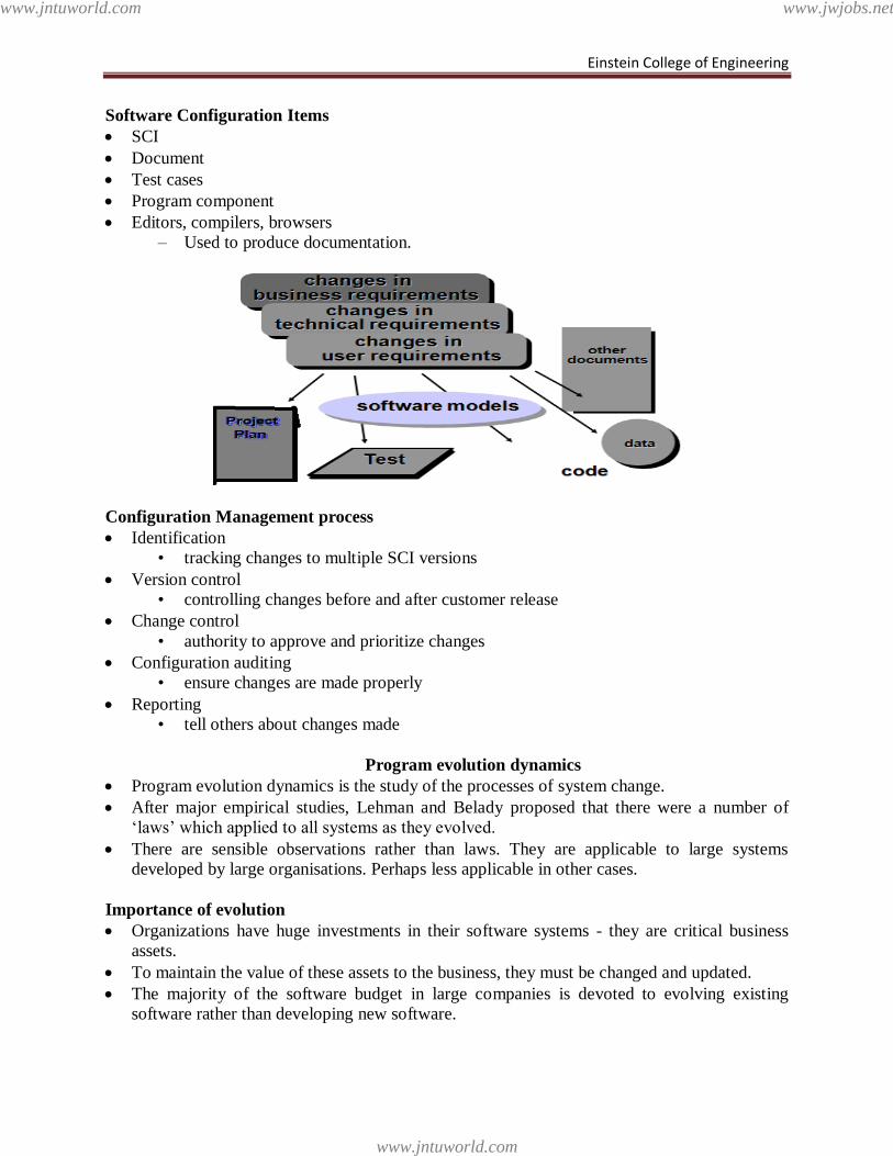
Einstein College of Engineering
Software Configuration Items
SCI
Document
Test cases
Program component
Editors, compilers, browsers
– Used to produce documentation.
Configuration Management process
Identification
• tracking changes to multiple SCI versions
Version control
• controlling changes before and after customer release
Change control
• authority to approve and prioritize changes
Configuration auditing
• ensure changes are made properly
Reporting
• tell others about changes made
Program evolution dynamics
Program evolution dynamics is the study of the processes of system change.
After major empirical studies, Lehman and Belady proposed that there were a number of
‗laws‘ which applied to all systems as they evolved.
There are sensible observations rather than laws. They are applicable to large systems
developed by large organisations. Perhaps less applicable in other cases.
Importance of evolution
Organizations have huge investments in their software systems - they are critical business
assets.
To maintain the value of these assets to the business, they must be changed and updated.
The majority of the software budget in large companies is devoted to evolving existing
software rather than developing new software.
www.jntuworld.com
www.jntuworld.com
www.jwjobs.net
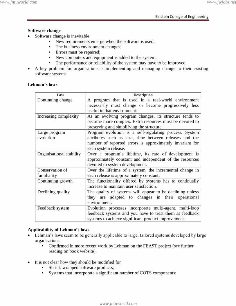
Einstein College of Engineering
Software change
Software change is inevitable
• New requirements emerge when the software is used;
• The business environment changes;
• Errors must be repaired;
• New computers and equipment is added to the system;
• The performance or reliability of the system may have to be improved.
A key problem for organisations is implementing and managing change to their existing
software systems.
Lehman’s laws
Law Description
Continuing change A program that is used in a real-world environment
necessarily must change or become progressively less
useful in that environment.
Increasing complexity As an evolving program changes, its structure tends to
become more complex. Extra resources must be devoted to
preserving and simplifying the structure.
Large program
evolution
Program evolution is a self-regulating process. System
attributes such as size, time between releases and the
number of reported errors is approximately invariant for
each system release.
Organisational stability Over a program‘s lifetime, its rate of development is
approximately constant and independent of the resources
devoted to system development.
Conservation of
familiarity
Over the lifetime of a system, the incremental change in
each release is approximately constant.
Continuing growth The functionality offered by systems has to continually
increase to maintain user satisfaction.
Declining quality The quality of systems will appear to be declining unless
they are adapted to changes in their operational
environment.
Feedback system Evolution processes incorporate multi-agent, multi-loop
feedback systems and you have to treat them as feedback
systems to achieve significant product improvement.
Applicability of Lehman’s laws
Lehman‘s laws seem to be generally applicable to large, tailored systems developed by large
organisations.
• Confirmed in more recent work by Lehman on the FEAST project (see further
reading on book website).
It is not clear how they should be modified for
• Shrink-wrapped software products;
• Systems that incorporate a significant number of COTS components;
www.jntuworld.com
www.jntuworld.com
www.jwjobs.net
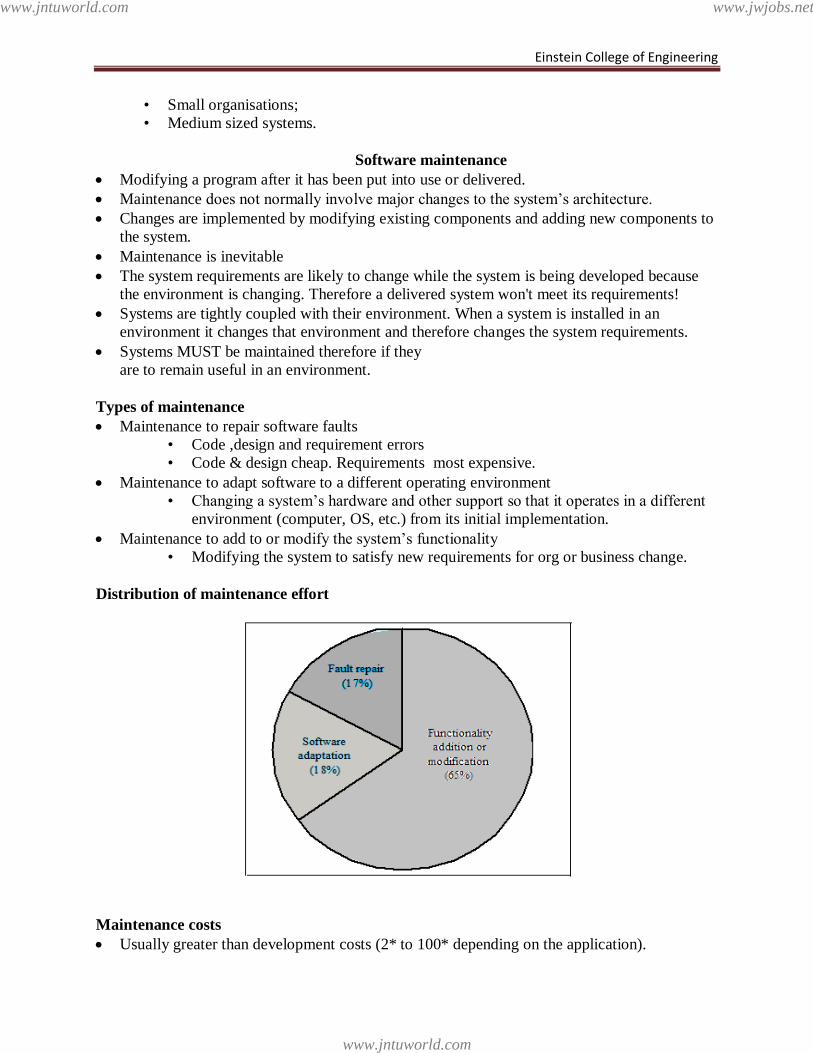
Einstein College of Engineering
• Small organisations;
• Medium sized systems.
Software maintenance
Modifying a program after it has been put into use or delivered.
Maintenance does not normally involve major changes to the system‘s architecture.
Changes are implemented by modifying existing components and adding new components to
the system.
Maintenance is inevitable
The system requirements are likely to change while the system is being developed because
the environment is changing. Therefore a delivered system won't meet its requirements!
Systems are tightly coupled with their environment. When a system is installed in an
environment it changes that environment and therefore changes the system requirements.
Systems MUST be maintained therefore if they
are to remain useful in an environment.
Types of maintenance
Maintenance to repair software faults
• Code ,design and requirement errors
• Code & design cheap. Requirements most expensive.
Maintenance to adapt software to a different operating environment
• Changing a system‘s hardware and other support so that it operates in a different
environment (computer, OS, etc.) from its initial implementation.
Maintenance to add to or modify the system‘s functionality
• Modifying the system to satisfy new requirements for org or business change.
Distribution of maintenance effort
Maintenance costs
Usually greater than development costs (2* to 100* depending on the application).
www.jntuworld.com
www.jntuworld.com
www.jwjobs.net
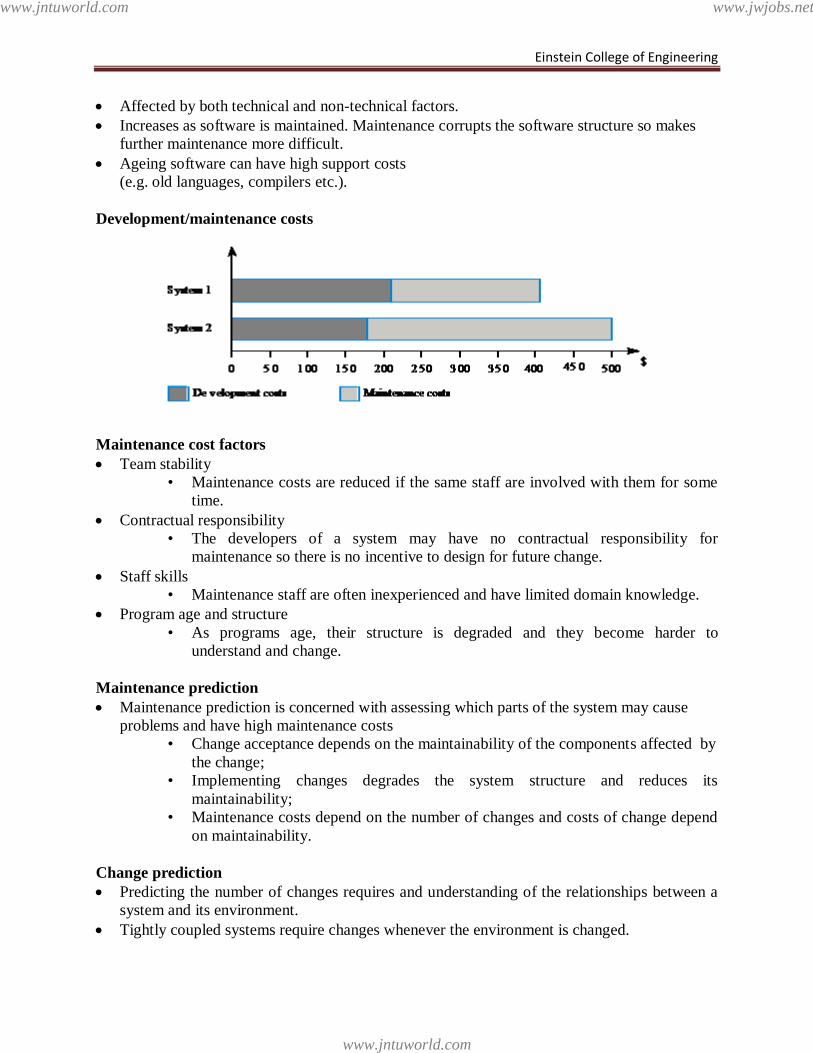
Einstein College of Engineering
Affected by both technical and non-technical factors.
Increases as software is maintained. Maintenance corrupts the software structure so makes
further maintenance more difficult.
Ageing software can have high support costs
(e.g. old languages, compilers etc.).
Development/maintenance costs
Maintenance cost factors
Team stability
• Maintenance costs are reduced if the same staff are involved with them for some
time.
Contractual responsibility
• The developers of a system may have no contractual responsibility for
maintenance so there is no incentive to design for future change.
Staff skills
• Maintenance staff are often inexperienced and have limited domain knowledge.
Program age and structure
• As programs age, their structure is degraded and they become harder to
understand and change.
Maintenance prediction
Maintenance prediction is concerned with assessing which parts of the system may cause
problems and have high maintenance costs
• Change acceptance depends on the maintainability of the components affected by
the change;
• Implementing changes degrades the system structure and reduces its
maintainability;
• Maintenance costs depend on the number of changes and costs of change depend
on maintainability.
Change prediction
Predicting the number of changes requires and understanding of the relationships between a
system and its environment.
Tightly coupled systems require changes whenever the environment is changed.
www.jntuworld.com
www.jntuworld.com
www.jwjobs.net
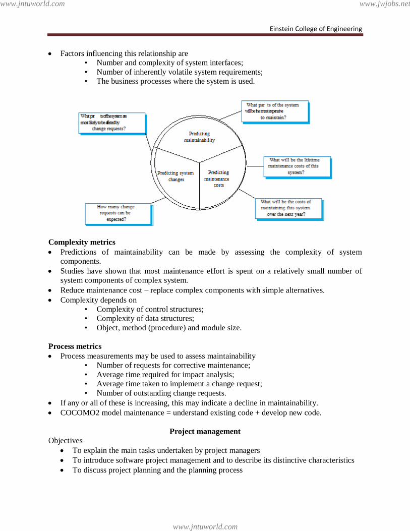
Einstein College of Engineering
Factors influencing this relationship are
• Number and complexity of system interfaces;
• Number of inherently volatile system requirements;
• The business processes where the system is used.
Complexity metrics
Predictions of maintainability can be made by assessing the complexity of system
components.
Studies have shown that most maintenance effort is spent on a relatively small number of
system components of complex system.
Reduce maintenance cost – replace complex components with simple alternatives.
Complexity depends on
• Complexity of control structures;
• Complexity of data structures;
• Object, method (procedure) and module size.
Process metrics
Process measurements may be used to assess maintainability
• Number of requests for corrective maintenance;
• Average time required for impact analysis;
• Average time taken to implement a change request;
• Number of outstanding change requests.
If any or all of these is increasing, this may indicate a decline in maintainability.
COCOMO2 model maintenance = understand existing code + develop new code.
Project management
Objectives
To explain the main tasks undertaken by project managers
To introduce software project management and to describe its distinctive characteristics
To discuss project planning and the planning process
www.jntuworld.com
www.jntuworld.com
www.jwjobs.net
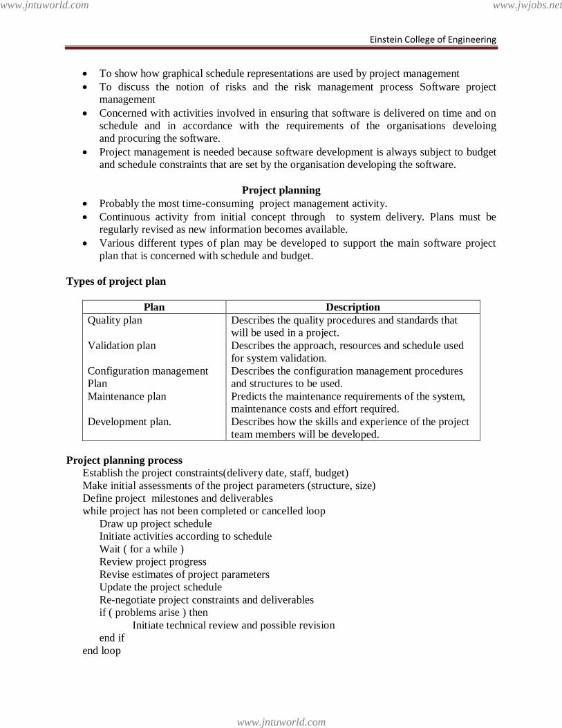
Einstein College of Engineering
To show how graphical schedule representations are used by project management
To discuss the notion of risks and the risk management process Software project
management
Concerned with activities involved in ensuring that software is delivered on time and on
schedule and in accordance with the requirements of the organisations develoing
and procuring the software.
Project management is needed because software development is always subject to budget
and schedule constraints that are set by the organisation developing the software.
Project planning
Probably the most time-consuming project management activity.
Continuous activity from initial concept through to system delivery. Plans must be
regularly revised as new information becomes available.
Various different types of plan may be developed to support the main software project
plan that is concerned with schedule and budget.
Types of project plan
Plan Description
Quality plan
Validation plan
Configuration management
Plan
Maintenance plan
Development plan.
Describes the quality procedures and standards that
will be used in a project.
Describes the approach, resources and schedule used
for system validation.
Describes the configuration management procedures
and structures to be used.
Predicts the maintenance requirements of the system,
maintenance costs and effort required.
Describes how the skills and experience of the project
team members will be developed.
Project planning process
Establish the project constraints(delivery date, staff, budget)
Make initial assessments of the project parameters (structure, size)
Define project milestones and deliverables
while project has not been completed or cancelled loop
Draw up project schedule
Initiate activities according to schedule
Wait ( for a while )
Review project progress
Revise estimates of project parameters
Update the project schedule
Re-negotiate project constraints and deliverables
if ( problems arise ) then
Initiate technical review and possible revision
end if
end loop
www.jntuworld.com
www.jntuworld.com
www.jwjobs.net
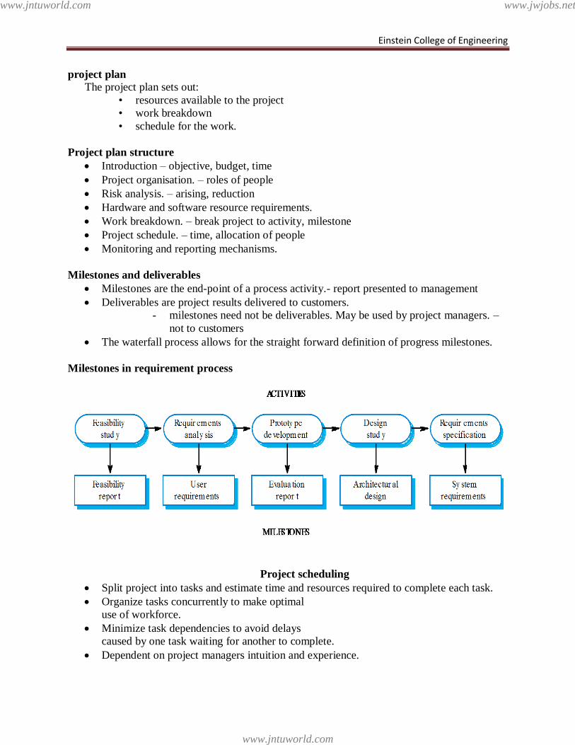
Einstein College of Engineering
project plan
The project plan sets out:
• resources available to the project
• work breakdown
• schedule for the work.
Project plan structure
Introduction – objective, budget, time
Project organisation. – roles of people
Risk analysis. – arising, reduction
Hardware and software resource requirements.
Work breakdown. – break project to activity, milestone
Project schedule. – time, allocation of people
Monitoring and reporting mechanisms.
Milestones and deliverables
Milestones are the end-point of a process activity.- report presented to management
Deliverables are project results delivered to customers.
- milestones need not be deliverables. May be used by project managers. –
not to customers
The waterfall process allows for the straight forward definition of progress milestones.
Milestones in requirement process
Project scheduling
Split project into tasks and estimate time and resources required to complete each task.
Organize tasks concurrently to make optimal
use of workforce.
Minimize task dependencies to avoid delays
caused by one task waiting for another to complete.
Dependent on project managers intuition and experience.
www.jntuworld.com
www.jntuworld.com
www.jwjobs.net
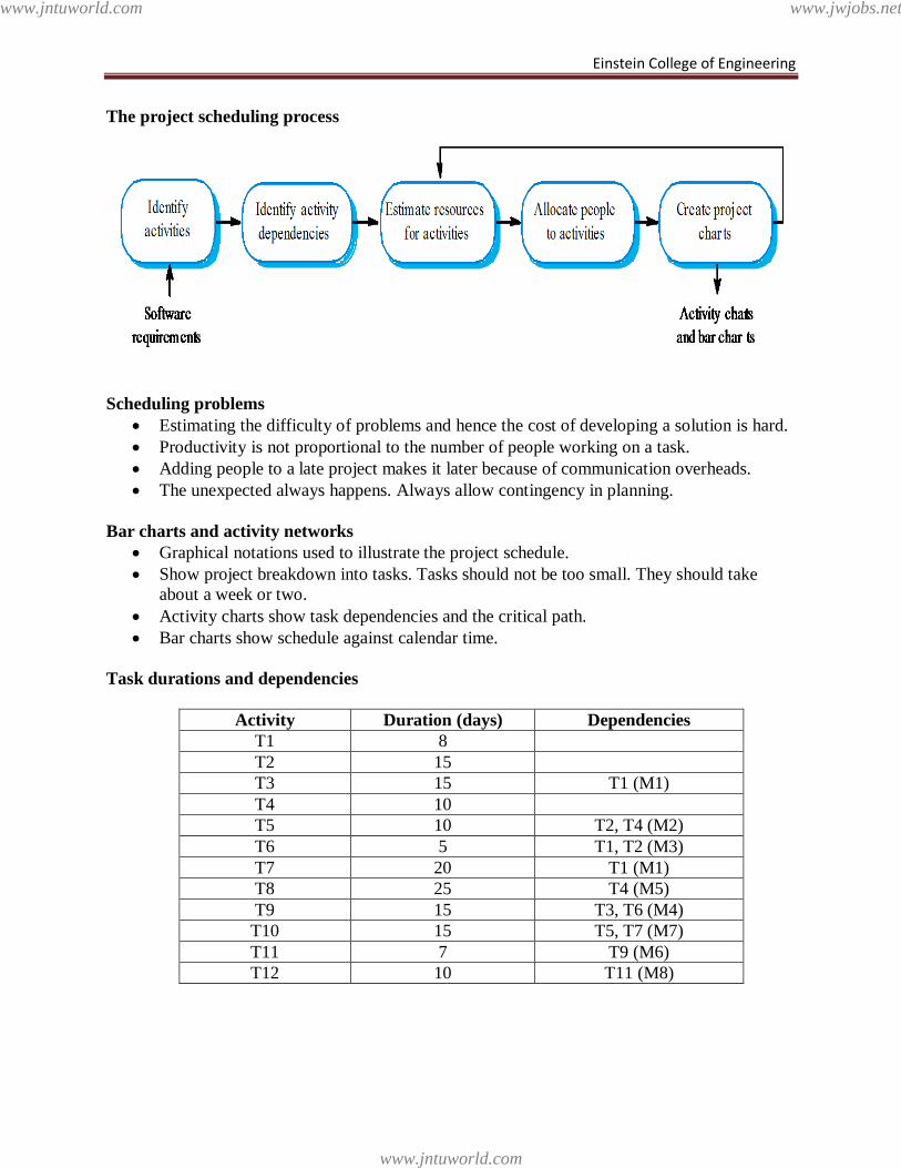
Einstein College of Engineering
The project scheduling process
Scheduling problems
Estimating the difficulty of problems and hence the cost of developing a solution is hard.
Productivity is not proportional to the number of people working on a task.
Adding people to a late project makes it later because of communication overheads.
The unexpected always happens. Always allow contingency in planning.
Bar charts and activity networks
Graphical notations used to illustrate the project schedule.
Show project breakdown into tasks. Tasks should not be too small. They should take
about a week or two.
Activity charts show task dependencies and the critical path.
Bar charts show schedule against calendar time.
Task durations and dependencies
Activity Duration (days) Dependencies
T1 8
T2 15
T3 15 T1 (M1)
T4 10
T5 10 T2, T4 (M2)
T6 5 T1, T2 (M3)
T7 20 T1 (M1)
T8 25 T4 (M5)
T9 15 T3, T6 (M4)
T10 15 T5, T7 (M7)
T11 7 T9 (M6)
T12 10 T11 (M8)
www.jntuworld.com
www.jntuworld.com
www.jwjobs.net
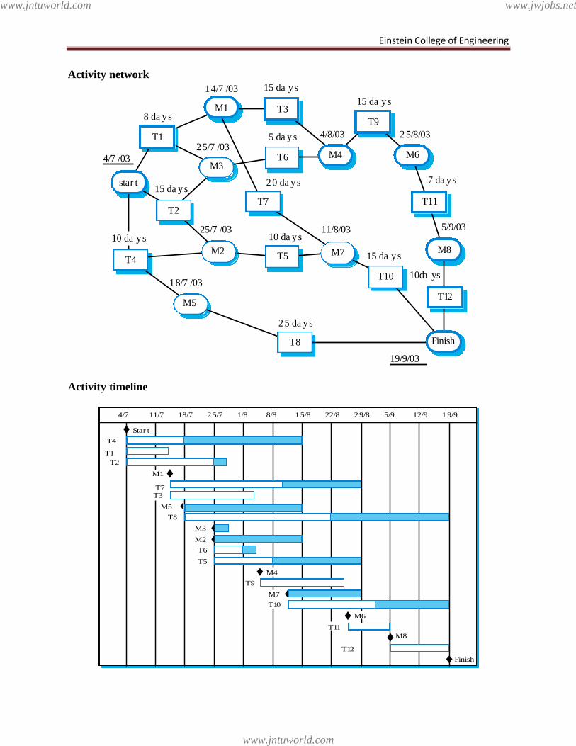
Einstein College of Engineering
Activity network
Activity timeline
star t
T2
M3T6
Finish
T10
M7T5
T7
M2T4
M5
T8
4/7 /03
8 da ys
14/7 /03 15 da ys
4/8/03
15 da ys
25/8/03
7 da ys
5/9/03
10 da ys
19/9/03
15 da ys
11/8/03
25 da ys
10 da ys
20 da ys
5 da ys25/7 /03
15 da ys
25/7 /03
18/7 /03
10 da ys
T1
M1 T3
T9
M6
T11
M8
T12
M4
4/7 11/7 18/7 25/7 1/8 8/8 15/8 22/8 29/8 5/9 12/9 19/9
T4
T1
T2
M1
T7T3
M5
T8
M3
M2
T6
T5
M4
T9
M7
T10
M6
T11
M8
T12
Star t
Finish
www.jntuworld.com
www.jntuworld.com
www.jwjobs.net
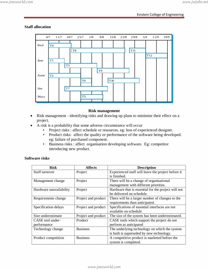
Einstein College of Engineering
Staff allocation
Risk management
Risk management - identifying risks and drawing up plans to minimise their effect on a
project.
A risk is a probability that some adverse circumstance will occur
• Project risks : affect schedule or resources. eg: loss of experienced designer.
• Product risks: affect the quality or performance of the software being developed.
eg: failure of purchased component.
• Business risks : affect organisation developing software. Eg: competitor
introducing new product.
Software risks
Risk Affects Description Staff turnover Project Experienced staff will leave the project before it
is finished.
Management change Project There will be a change of organisational
management with different priorities.
Hardware unavailability Project Hardware that is essential for the project will not be delivered on schedule.
Requirements change Project and product There will be a larger number of changes to the
requirements than anticipated.
Specification delays Project and product Specifications of essential interfaces are not available on schedule
Size underestimate Project and product The size of the system has been underestimated.
CASE tool under-
performance
Product CASE tools which support the project do not
perform as anticipated
Technology change Business The underlying technology on which the system
is built is superseded by new technology.
Product competition Business A competitive product is marketed before the
system is completed.
4/7 11/7 18/7 25/7 1/8 8/8 15/8 22/8 29/8 5/9 12/9 19/9
T4
T8 T11
T12
T1
T3
T9
T2
T6 T10
T7
T5
Fred
Jane
Anne
Mary
Jim
www.jntuworld.com
www.jntuworld.com
www.jwjobs.net
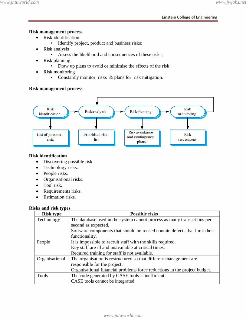
Einstein College of Engineering
Risk management process
Risk identification
• Identify project, product and business risks;
Risk analysis
• Assess the likelihood and consequences of these risks;
Risk planning
• Draw up plans to avoid or minimise the effects of the risk;
Risk monitoring
• Constantly monitor risks & plans for risk mitigation.
Risk management process
Risk identification
Discovering possible risk
Technology risks.
People risks.
Organisational risks.
Tool risk.
Requirements risks.
Estimation risks.
Risks and risk types
Risk type Possible risks
Technology The database used in the system cannot process as many transactions per
second as expected.
Software components that should be reused contain defects that limit their
functionality.
People It is impossible to recruit staff with the skills required.
Key staff are ill and unavailable at critical times.
Required training for staff is not available.
Organisational The organisation is restructured so that different management are
responsible for the project.
Organisational financial problems force reductions in the project budget.
Tools The code generated by CASE tools is inefficient.
CASE tools cannot be integrated.
www.jntuworld.com
www.jntuworld.com
www.jwjobs.net
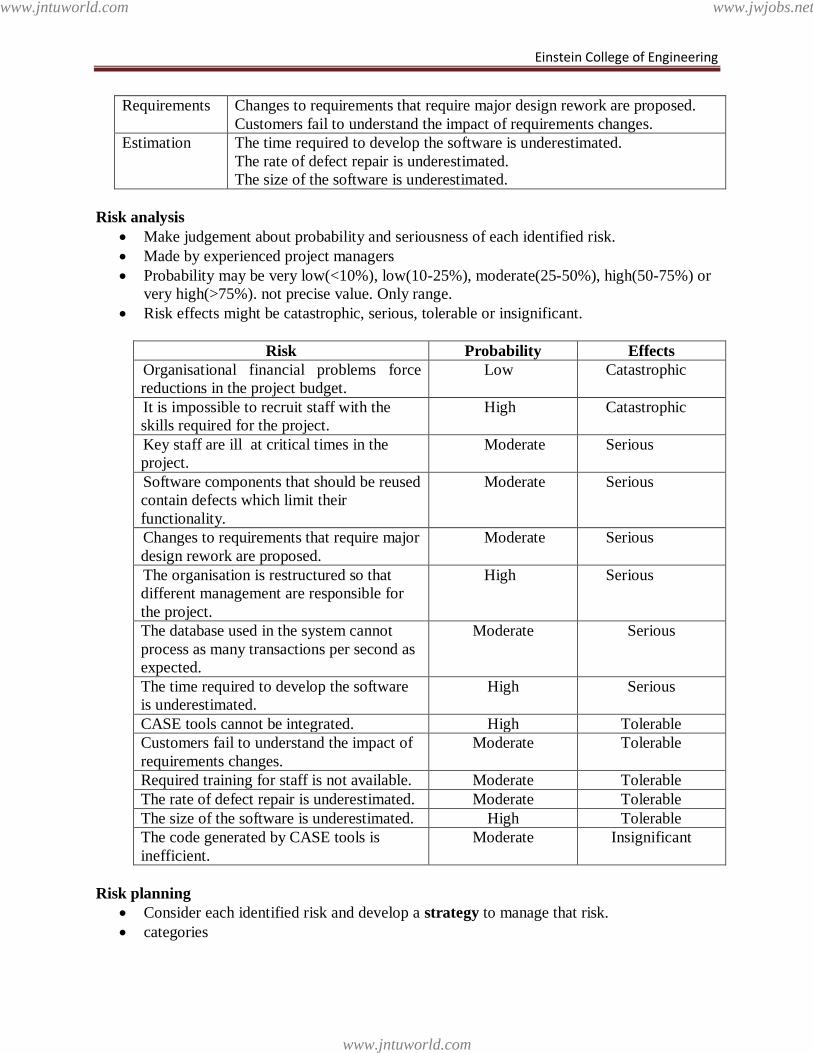
Einstein College of Engineering
Requirements Changes to requirements that require major design rework are proposed.
Customers fail to understand the impact of requirements changes.
Estimation The time required to develop the software is underestimated.
The rate of defect repair is underestimated.
The size of the software is underestimated.
Risk analysis
Make judgement about probability and seriousness of each identified risk.
Made by experienced project managers
Probability may be very low(<10%), low(10-25%), moderate(25-50%), high(50-75%) or
very high(>75%). not precise value. Only range.
Risk effects might be catastrophic, serious, tolerable or insignificant.
Risk Probability Effects
Organisational financial problems force
reductions in the project budget.
Low Catastrophic
It is impossible to recruit staff with the
skills required for the project.
High Catastrophic
Key staff are ill at critical times in the
project.
Moderate Serious
Software components that should be reused
contain defects which limit their
functionality.
Moderate Serious
Changes to requirements that require major
design rework are proposed.
Moderate Serious
The organisation is restructured so that
different management are responsible for
the project.
High Serious
The database used in the system cannot
process as many transactions per second as
expected.
Moderate Serious
The time required to develop the software
is underestimated.
High Serious
CASE tools cannot be integrated. High Tolerable
Customers fail to understand the impact of
requirements changes.
Moderate Tolerable
Required training for staff is not available. Moderate Tolerable
The rate of defect repair is underestimated. Moderate Tolerable
The size of the software is underestimated. High Tolerable
The code generated by CASE tools is
inefficient.
Moderate Insignificant
Risk planning
Consider each identified risk and develop a strategy to manage that risk.
categories
www.jntuworld.com
www.jntuworld.com
www.jwjobs.net
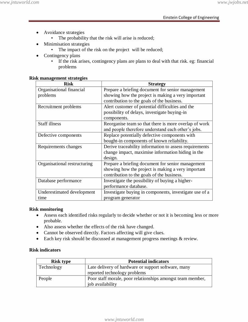
Einstein College of Engineering
Avoidance strategies
• The probability that the risk will arise is reduced;
Minimisation strategies
• The impact of the risk on the project will be reduced;
Contingency plans
• If the risk arises, contingency plans are plans to deal with that risk. eg: financial
problems
Risk management strategies
Risk Strategy
Organisational financial
problems
Prepare a briefing document for senior management
showing how the project is making a very important
contribution to the goals of the business.
Recruitment problems Alert customer of potential difficulties and the
possibility of delays, investigate buying-in
components.
Staff illness Reorganise team so that there is more overlap of work
and people therefore understand each other‘s jobs.
Defective components Replace potentially defective components with
bought-in components of known reliability.
Requirements changes Derive traceability information to assess requirements
change impact, maximise information hiding in the
design.
Organisational restructuring Prepare a briefing document for senior management
showing how the project is making a very important
contribution to the goals of the business.
Database performance Investigate the possibility of buying a higher-
performance database.
Underestimated development
time
Investigate buying in components, investigate use of a
program generator
Risk monitoring
Assess each identified risks regularly to decide whether or not it is becoming less or more
probable.
Also assess whether the effects of the risk have changed.
Cannot be observed directly. Factors affecting will give clues.
Each key risk should be discussed at management progress meetings & review.
Risk indicators
Risk type Potential indicators
Technology Late delivery of hardware or support software, many
reported technology problems
People Poor staff morale, poor relationships amongst team member,
job availability
www.jntuworld.com
www.jntuworld.com
www.jwjobs.net
Einstein College of Engineering
Organisational Organisational gossip, lack of action by senior management
Tools Reluctance by team members to use tools, complaints about
CASE tools, demands for higher-powered workstations
Requirements Many requirements change requests, customer complaints
Estimation Failure to meet agreed schedule, failure to clear reported
defects
CASE Tools
Computer-Aided Software Engineering
Prerequisites to tool use
– Need a collection of useful tools that help in every step of building a product
– Need an organized layout that enables tools to be found quickly and used
efficiently
– Need a skilled craftsperson who understands how to use the tools effectively
CASE Tools
Upper CASE
– requirements
– specification
– planning
– design
Lower CASE
– implementation
– integration
– maintenance
CASE tool classification
Functional perspective
Process perspective
Integration perspective
CASE Tool Taxonomy
Project planning tools
- used for cost and effort estimation, and project scheduling
Business process engineering tools
- represent business data objects, their relationships, and flow of the data objects
between company business areas
Process modeling and management tools
- represent key elements of processes and provide links to other tools that provide
support to defined process activities
Risk analysis tools
- help project managers build risk tables by providing detailed guidance in the
identification and analysis of risks
Requirements tracing tools
- provide systematic database-like approach to tracking requirement status
beginning with specification
Quality assurance tools
www.jntuworld.com
www.jntuworld.com
www.jwjobs.net
Einstein College of Engineering
- metrics tools that audit source code to determine compliance with language
standards or tools that extract metrics to project the quality of software being built
Documentation tools
- provide opportunities for improved productivity by reducing the amount of time
needed to produce work products
Database management tools
- RDMS and OODMS serve as the foundation for the establishment of the CASE
repository
Software configuration management tools
- uses the CASE repository to assist with all SCM tasks (identification, version
control, change control, auditing, status accounting)
Analysis and design tools
- enable the software engineer to create analysis and design models of the system to
be built, perform consistency checking between models
Interface design and development tools
- toolkits of interface components, often part environment with a GUI to allow
rapid prototyping of user interface designs
Prototyping tools
- enable rapid definition of screen layouts, data design, and report generation
Programming tools
- compilers, editors, debuggers, OO programming environments, fourth generation
languages, graphical programming environments, applications generators, and
database query generators
Web development tools
- assist with the generation of web page text, graphics, forms, scripts, applets, etc.
Test management tools
- coordinate regression testing, compare actual and expected output, conduct batch
testing, and serve as generic test drivers
Client/server testing tools
- exercise the GUI and network communications requirements for the client and
server
CASE tool support
Requirements storage
- Requirements should be managed in a secure, managed data store
Change management
- The process of change management is a workflow process whose stages can be
defined and information flow between these stages partially automated
Traceability management
- Automated retrieval of the links between requirements
DBMS Features Needed for CASE Repositories
Non-redundant data storage
High-level access
Data independence
www.jntuworld.com
www.jntuworld.com
www.jwjobs.net

Einstein College of Engineering
Transaction control
Multi-user support
www.jntuworld.com
www.jntuworld.com
www.jwjobs.net