Software Engineering I: Software Technology WS 2008/09 · Software Engineering I: Software...
95
1 © 2008 Bernd Bruegge Software Engineering SS 2008 Bernd Bruegge Applied Software Engineering Technische Universitaet Muenchen Software Engineering I: Software Technology WS 2008/09 Analysis
-
Upload
truongdang -
Category
Documents
-
view
216 -
download
2
Transcript of Software Engineering I: Software Technology WS 2008/09 · Software Engineering I: Software...

1 © 2008 Bernd Bruegge Software Engineering SS 2008
Bernd Bruegge Applied Software Engineering
Technische Universitaet Muenchen
Software Engineering I: Software Technology
WS 2008/09
Analysis

2 © 2008 Bernd Bruegge Software Engineering SS 2008
Outline
Recall: System modeling = Functional modeling + Object modeling + Dynamic modeling
Requirements Elicitation leads to Functional Model Next topic: Object modeling
• Activities during object modeling • Object identification • Object types
• Entity, boundary and control objects • Stereotypes • Abott’s technique
• Helps in object identification.

3 © 2008 Bernd Bruegge Software Engineering SS 2008
Lecture at Munich Airport
• Michael Zaddach • Senior Vice President, Munich Airport
• Possible lecture dates: • Nov 11, 16:15-17:45 • Nov 18, 16:15-17:45
• Live Demonstration of the MUC baggage system at the airport
• Nov 11, after the lecture • Nov 18, after the lecture
• Issue: Location of the lecture? • Proposal: Lecture at the airport!

4 © 2008 Bernd Bruegge Software Engineering SS 2008
From Use Cases to Objects Level 1 Use Case
Level 2 Use Cases
Level 3 Use Cases
Operations
Participating Objects
Le v el 2
Le v el 1
Le v el 2
Le v el 3 Le v el 3
Le v el 4 Le v el 4
Le v el 3
A B

5 © 2008 Bernd Bruegge Software Engineering SS 2008
From Use Cases to Objects: Why Functional Decomposition is not Enough
Scenarios
Level 1 Use Cases
Level 2 Use Cases
Operations
Participating Objects
Le v el 2
Le v el 1
Le v el 2
Le v el 3 Le v el 3
Le v el 4 Le v el 4
Le v el 3
A B

6 © 2008 Bernd Bruegge Software Engineering SS 2008
Activities during Object Modeling Main goal: Find the important abstractions • Steps during object modeling
1. Class identification • Based on the fundamental assumption that we can
find abstractions 2. Find the attributes 3. Find the operations 4. Find the associations between classes
• Order of steps • Goal: get the desired abstractions • Order of steps secondary, only a heuristic
• What happens if we find the wrong abstractions? • We iterate and revise the model

7 © 2008 Bernd Bruegge Software Engineering SS 2008
Class Identification
• Approaches • Application domain approach
• Ask application domain experts to identify relevant abstractions
• Syntactic approach • Start with use cases • Analyze the text to identify the objects • Extract participating objects from flow of events
• Design patterns approach • Use reusable design patterns
• Component-based approach • Identify existing solution classes.

8 © 2008 Bernd Bruegge Software Engineering SS 2008
Class identification is a Hard Problem
• One problem: Definition of the system boundary:
• Which abstractions are outside, which abstractions are inside the system boundary?
• Actors are outside the system • Classes/Objects are inside the system.

9 © 2008 Bernd Bruegge Software Engineering SS 2008
There are 3 different types of Objects
• Entity Objects • Represent the persistent information tracked by the
system (Application domain objects, also called “Business objects”)
• Boundary Objects • Represent the interaction between the user and the
system
• Control Objects • Represent the control tasks performed by the system.

10 © 2008 Bernd Bruegge Software Engineering SS 2008
Example: Modeling A Watch
Year
Month
Day
ChangeDate Button
LCDDisplay
Entity Objects Control Object Boundary Objects

Object Types in UML • We can use the stereotype mechanism to
distinguish the 3 types of objects
<<Entity>> Year <<Control>>
ChangeDate
<<Boundary>> Button
<<Entitity>> Month
<<Entity>> Day
<<Boundary>> LCDDisplay
Entity Object Control Object Boundary Object

12 © 2008 Bernd Bruegge Software Engineering SS 2008
UML is an Extensible Language • Stereotypes allow you to extend the vocabulary of the
UML so that you can create new model elements, derived from existing ones
• Examples: • Stereotypes can also be used to classify method behavior such
as <<constructor>>, <<getter>> or <<setter>> • To indicate the interface of a subsystem or system, we use the
stereotype <<interface>> (Lecture System Design) • Stereotypes can also be represented with icons and
graphics: • This can increase the readability of UML diagrams.

13 © 2008 Bernd Bruegge Software Engineering SS 2008
Icons for Stereotypes
• One can use icons for stereotypes • When the stereotype is applied to a UML model element, the
icon is displayed beside or above the name
Year ChangeDate Button
Entity Object Control Object Boundary Object Actor
WatchUser
These icons were first used in Objectory, Ivar Jacobsen’s CASE tool for OOSE

14 © 2008 Bernd Bruegge Software Engineering SS 2008
Ivar Jacobson, James Rumbaugh, Grady Booch (The 3 UML “Amigos”)
Invented use cases, sequence diagrams and collaboration diagrams to model software controlled telephone switches at Ericsson (1967)
One of the first OO modelers Developed the Booch Method (“Objects as clouds”, 1991)
Developed the OMT Notation (Object Modeling Technique) Added inheritance to E/R Modeling, 1991
Picture Source http://en.wikipedia.org

15 © 2008 Bernd Bruegge Software Engineering SS 2008
OMT Notation (Object Modeling Technique)
OMT is no longer an active language. However, it is still important to know about it , because it is the notation used in the book “Design Patterns”.

16 © 2008 Bernd Bruegge Software Engineering SS 2008
Booch Notation
Mapping Booch to OMT:� http://www1.inf.tu-dresden.de/~rm1/booch_omt/booch_omt.html

17 © 2008 Bernd Bruegge Software Engineering SS 2008
Why do we distinguish 3 Object Types?
• Having three types of object leads to models that are more resistent (“resilient”) to change
• The interface of a system changes more likely than the control
• The way the system is controlled changes more likely than entities in the application domain
• Object types originated in Smalltalk: • Model, View, Controller (MVC)
Model <-> Entity Object View <-> Boundary Object Controller <-> Control Object

18 © 2008 Bernd Bruegge Software Engineering SS 2008
Smalltalk
• Smalltalk was developed at Xerox Parc (now parco.com) in the 1970s.
• Smalltak was used to prototype the WIMP (windows, icons, menus, pointers) interface, the cornerstone for today's graphical user interfaces.
• Smalltalk was developed by Adele Goldberg and Alan Kay.
Picture Source http://en.wikipedia.org

19 © 2008 Bernd Bruegge Software Engineering SS 2008
How do we find Objects? • Pick a use case and look at the flow of events • Do a textual analysis (noun-verb analysis)
• Nouns are candidates for objects/classes • Verbs are candidates for operations • This is also called Abbott’s Technique
• After objects/classes are found, identify their types
• Identify real world entities that the system needs to keep track of (FieldOfficer Entity Object)
• Identify real world procedures that the system needs to keep track of (EmergencyPlan Control Object)
• Identify interface artifacts (PoliceStation Boundary Object).

20 © 2008 Bernd Bruegge Software Engineering SS 2008
Example for using the Technique
• The customer enters the store to buy a toy.
• It has to be a toy that his daughter likes and it must cost less than 50 Euro.
• He tries a videogame, which uses a data glove and a head-mounted display. He likes it.
• An assistant helps him. • The suitability of the game depends on the age of the child.
• His daughter is only 3 years old. • The assistant recommends another type of toy, namely the boardgame “Monopoly".
Flow of Events:

21 © 2008 Bernd Bruegge Software Engineering SS 2008
Textual Analysis (Abbot’s Technique)
Part of speech
Proper noun
Improper noun
Doing verb
being verb
having verb
modal verb
adjective
transitive verb
intransitive verb
UML model component
object
class
operation
inheritance
aggregation
constraint
attribute
operation
Constraint, class, association
Example
“Monopoly”
Toy
Buy, recommend
is-a
has an
must be
dangerous
enter
depends on

videogame
• The customer enters the store to buy a toy. It has to be a toy that his daughter likes and it must cost less than 50 Euro. He tries a videogame, which uses a data glove and a head-mounted display. He likes it.
Generating a Class Diagram from Flow of Events
An assistant helps him. The suitability of the game depends on the age of the child. His daughter is only 3 years old. The assistant recommends another type of toy, namely a boardgame. The customer buy the game and leaves the store
customer enters
depends
store Customer
?
enter()
toy
daughter
suitable
*
less than 50
store
enter()
toy
buy()
toy
age
videogame
daughter
boardgame
Flow of events:
Toy
price buy() like()
buy
type of toy boardgame
daughter age

23 © 2008 Bernd Bruegge Software Engineering SS 2008
Ways to find Objects 10 31 2008
• Syntactical investigation with Abbot‘s technique: • Flow of events in use cases • Problem statement
• Use other knowledge sources: • Application knowledge: End users and experts know
the abstractions of the application domain • Solution knowledge: Abstractions in the solution
domain • General world knowledge: Your generic knowledge and
intuition

24 © 2008 Bernd Bruegge Software Engineering SS 2008
Order of Activities for Object Identification
1. Formulate a few scenarios with help from an end user or application domain expert
2. Extract the use cases from the scenarios, with the help of an application domain expert
3. Then proceed in parallel with the following: • Analyse the flow of events in each use case
using Abbot's textual analysis technique • Generate the UML class diagram.

25 © 2008 Bernd Bruegge Software Engineering SS 2008
Steps in Generating Class Diagrams
1. Class identification (textual analysis, domain expert)
2. Identification of attributes and operations (sometimes before the classes are found!)
3. Identification of associations between classes 4. Identification of multiplicities 5. Identification of roles 6. Identification of inheritance

26 © 2008 Bernd Bruegge Software Engineering SS 2008
Who uses Class Diagrams?
• Purpose of class diagrams • The description of the static properties of a system
• The main users of class diagrams: • The application domain expert
• uses class diagrams to model the application domain (including taxonomies)
• during requirements elicitation and analysis • The developer
• uses class diagrams during the development of a system
• during analysis, system design, object design and implementation.

27 © 2008 Bernd Bruegge Software Engineering SS 2008
Who does not use Class Diagrams?
• The client and the end user are often not interested in class diagrams
• Clients usually focus more on project management issues
• End users usually focus on the functionality of the system.

28 © 2008 Bernd Bruegge Software Engineering SS 2008
(Intermediate) Summary
• System modeling • Functional modeling+object modeling+dynamic modeling
• Functional modeling • From scenarios to use cases to objects
• Object modeling is the central activity • Class identification is a major activity of object modeling • Easy syntactic rules to find classes and objects • Abbot’s Technique
• Class diagrams are the “center of the universe” for the object-oriented developer
• The end user focuses more on the functional model and and usability.

29 © 2008 Bernd Bruegge Software Engineering SS 2008
“Historical” Readings
OMT: • James Rumbaugh, Michael Blaha, William Premerlani, and
Frederick Eddy. Object-Oriented Modeling and Design with UML (2nd Edition by Rumbaugh and Blaha), Prentice Hall 1991 and 2004.
OOSE and Use Cases: • Ivar Jacobson, Magnus Christerson, Patrik Jonsson, Gunnar
Overgaard Object-Oriented Software Engineering: A Use Case Driven Approach (ACM Press) Addison-Wesley, 1992, ISBN 0201544350
Booch Method: • Booch, Grady (1993). Object-oriented Analysis and Design
with Applications, 2nd ed., Redwood City: Benjamin Cummings.

30 © 2008 Bernd Bruegge Software Engineering SS 2008
Developers have different Views on Class Diagrams
• According to the development activity, a developer plays different roles:
• Analyst • System Designer • Object Designer • Implementor
• Each of these roles has a different view about the class diagram (the object model).

31 © 2008 Bernd Bruegge Software Engineering SS 2008
The View of the Analyst
• The analyst is interested • in application classes: The associations between
classes are relationships between abstractions in the application domain
• operations and attributes of the application classes (difference to E/R models!)
• The analyst uses inheritance in the model to reflect the taxonomies in the application domain
• Taxonomy: An is-a-hierarchy of abstractions in an application domain
• The analyst is not interested • in the exact signature of operations • in solution domain classes.

32 © 2008 Bernd Bruegge Software Engineering SS 2008
The View of the Designer • The designer focuses on the solution of the
problem, that is, the solution domain • The associations between classes now mean
references (pointers) between classes in the application or solution domain
• An important design task is the specification of interfaces:
• The designer describes the interface of classes and the interface of subsystems
• Subsystems originate from modules (term often used during analysis):
• Module: a collection of classes • Subsystem: a collection of classes with an interface
• Subsystems are modeled in UML with a package.

33 © 2008 Bernd Bruegge Software Engineering SS 2008
Goals of the Designer
• The most important design goals for the designer are design usability and design reusability
• Design usability: the subsystem interfaces are usable from as many classes as possible within in the system
• Design reusability: The subsystem interfaces are designed in a way, that they can also be reused by other (future) software systems
=> Class libraries => Frameworks => Design patterns.

34 © 2008 Bernd Bruegge Software Engineering SS 2008
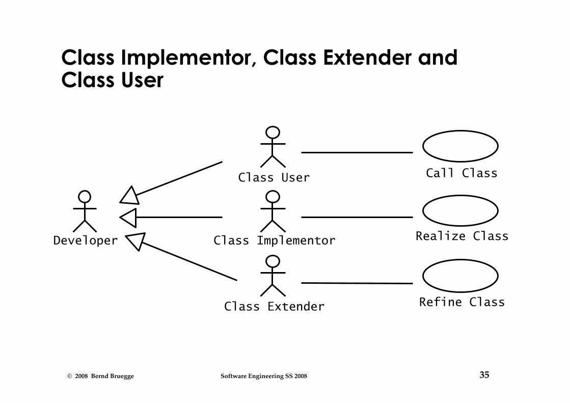
The View of the Implementor
• Class implementor • Must realize the interface of a class in a programming
language • Interested in appropriate data structures (for the
attributes) and algorithms (for the operations)
• Class extender • Interested in how to extend a class to solve a new
problem or to adapt to a change in the application domain
• Class user • The class user is interested in the signatures of the
class operations and conditions, under which they can be invoked
• The class user is not interested in the implementation of the class.
35 © 2008 Bernd Bruegge Software Engineering SS 2008
Class Implementor, Class Extender and Class User
Developer
Call Class
Class Extender
Class Implementor
Class User
Realize Class
Refine Class

36 © 2008 Bernd Bruegge Software Engineering SS 2008
Why do we distinguish different Users of Class Diagrams?
• Models often don‘t distinguish between application domain classes and solution domain classes
• Reason: Modeling languages like UML allow the use of both types of classes in the same model
• “address book“, “array" • Preferred: No solution classes in the analysis model
• Many systems don‘t distinguish between the specification and the implementation of a class
• Reason: Object-oriented programming languages allow the simultaneous use of specification and implementation of a class
• Preferred: We distinguish between analysis model and object design model. The analysis design model does not contain any implementation specification.

37 © 2008 Bernd Bruegge Software Engineering SS 2008
Analysis model vs. object design model
• The analysis model is constructed during the analysis phase
• Main stake holders: End user, customer, analyst • The class diagrams contains only application domain
classes
• The object design model (sometimes also called specification model) is created during the object design phase
• Main stake holders: class specifiers, class implementors, class extenders and class users
• The class diagrams contain application domain as well as solution domain classes.

38 © 2008 Bernd Bruegge Software Engineering SS 2008
Stop! I am lost

39 © 2008 Bernd Bruegge Software Engineering SS 2008
I cannot follow the lectures. Where are we?
• We have covered Ch 1 - 3 • We are in the middle of Chapter 4
• Functional modeling: Read again Ch 2, pp. 46 - 51 • Structural modeling: Read again Ch 2, pp.52 - 59
• From use cases to class diagrams • Identify participatory objects in flow of events descriptions
• Exercise: Apply Abbot’s technique to Fig. 5-7, p. 181 • Identify entity, control and boundary objects
• Heuristics to find these types: Ch 5, Section 5.4
• We are now focusing on identyfing classes during dynamic modeling

40 © 2008 Bernd Bruegge Software Engineering SS 2008
How do you find classes and objects?
• We have already established several sources for class and object identification: • Application domain analysis: We find classes by talking
to the client and identify abstractions by observing the end user
• General world knowledge and intuition • Textual analysis of event flow in use cases (Abbot)
• Today we identify classes and objects from dynamic models
• Two good heuristics: 1. Actions and activities are candidates for public
operations on classes 2. Activity lines in sequence diagrams are candidates for
objects.

41 © 2008 Bernd Bruegge Software Engineering SS 2008
Dynamic Modeling
• Definition of a dynamic model: • Describes the components of the system that have
interesting dynamic behavior
• The dynamic model is described with • State diagrams: One state diagram for each class with
interesting dynamic behavior • Classes without interesting dynamic behavior are
not modeled with state diagrams • Sequence diagrams: For modeling the interaction
between classes
• Purpose: • Detect and supply operations for the object model.

42 © 2008 Bernd Bruegge Software Engineering SS 2008
How do we detect Operations?
• We look for objects, who are interacting and extract their “protocol”
• “How are you?””I am fine”.
• We look for objects, who have interesting behavior
• Star, Banking account
• Good starting point: Flow of events in a use case description
• From the flow of events we construct the sequence diagram
• In the sequence diagram we look for the “participating objects”.

43 © 2008 Bernd Bruegge Software Engineering SS 2008
Flow of Events
• What is an Event? • Something that happens at a point in time • An event sends information from one object to another
• Events can have associations with each other: • Temporally related events:
• Event A always “happens before” event B • Event B always “happens after” event C
• Unrelated events: • Events that happen concurrently (A and B can
happen at the same time)
• What is a Flow of Events? • A sequence of temporally related and unrelated events.

44 © 2008 Bernd Bruegge Software Engineering SS 2008
Event • An event is an important abstraction in a
dynamic model. Therefore we model the events in a system usually as classes
• Event classes can be grouped in event classes with a hierarchical structure • This means, we can define a Event taxonomy
• The term ‘Event’ is also used in two other ways: • Instance of an event class:
• “Slide 44 shown on Tuesday November 4 at 16:50”. Event class “Lecture Given”, Subclass “Slide Shown”
• Attribute of an event class • Mouse click (buttonNr, direction, location) • Slide Update(3:45 PM, 11/4/2008) • Train_Leaves(4:45pm, Manhattan)

45 © 2008 Bernd Bruegge Software Engineering SS 2008
Sequence Diagram
• A sequence diagram is a graphical description of the flow of events
• The objects participating in the flow of events are called participating objects
• A good rule of thumb for finding participating objects:
• A event always has a sender and a receiver • Find the sender and receiver for each event =>These are the objects participating in the use case.

46 © 2008 Bernd Bruegge Software Engineering SS 2008
• Assume a “Get SeatPosition” use case with the following flow of events:
1. Establish connection between smart card and onboard computer
2. Establish connection between onboard computer and seat
3. Get current seat position and store on smart card
• Where are the objects?
An Example

47 © 2008 Bernd Bruegge Software Engineering SS 2008
Sequence Diagram for “Get SeatPosition”
Establish Connection
Accept Connection
Accept Connection
Get SeatPosition
“500,575,300”
Smart Card Onboard Computer Seat
Establish Connection 1. Establish connection between smart card and onboard computer�
2. Establish connection between onboard computer and seat (actually seat sensor)�
3. Get current seat position and store on smart card.
time

48 © 2008 Bernd Bruegge Software Engineering SS 2008
Heuristics for Sequence Diagrams
• Creation of Objects Heuristic: 1. Create control objects at beginning of the flow of events
2. The control objects then create the boundary objects
• Access of Objects Heuristic: • Entity objects are accessed by control and boundary objects
• Entity objects should not access boundary or control objects.
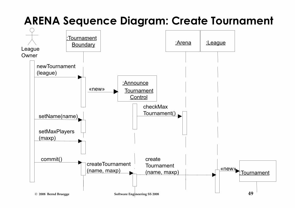
• Layout Heuristic: 1st column: Should be the actor of the use case 2nd column: Should be a boundary object 3rd column: Should be the control object that manages the rest of the use case
49 © 2008 Bernd Bruegge Software Engineering SS 2008
:Tournament «new»
ARENA Sequence Diagram: Create Tournament
League Owner
:Tournament Boundary
newTournament (league)
:Announce Tournament
Control «new»
setName(name) setMaxPlayers (maxp)
commit() createTournament (name, maxp)
checkMax Tournament()
create Tournament (name, maxp)
:Arena :League

50 © 2008 Bernd Bruegge Software Engineering SS 2008
Impact on ARENA’s Object Model
• Let’s assume ARENA’s object model contains - at this modeling stage - the objects
• League Owner, Arena, League, Tournament, Match and Player
• The Flow of Events identifies 2 new Classes • Tournament Boundary, Announce_Tournament_Control

51 © 2008 Bernd Bruegge Software Engineering SS 2008
Attributes Operations
League
Attributes Operations
Tournament
Attributes Operations
Player Attributes Operations
Match
Attributes Operations
League Owner 1 *
* *

52 © 2008 Bernd Bruegge Software Engineering SS 2008
Attributes Operations
League
Attributes Operations
Tournament
Attributes Operations
Player Attributes Operations
Match
Attributes Operations
League Owner 1 *
* *
Attributes Operations
Tournament_ Boundary
Attributes Operations
Announce_ Tournament_
Control

53 © 2008 Bernd Bruegge Software Engineering SS 2008
Impact on ARENA’s Object Model (2) • The sequence diagram (slide 49) also supplies us
with many new events • newTournament(league) • setName(name) • setMaxPlayers(max) • commit • checkMaxTournament() • createTournament
• Question: Who owns these events? • Answer (Heuristic): For each object that receives an event there should be a public operation in the associated class
A good choice for the name of the operation is usually the name of the event.

54 © 2008 Bernd Bruegge Software Engineering SS 2008
Example from the Sequence Diagram
createTournament (name, maxp)
create Tournament (name, maxp)
League Owner
:Tournament Boundary
newTournament (league)
:Announce Tournament
Control «new»
setName(name) setMaxPlayers (maxp)
commit()
checkMax Tournament()
:Arena :League
:Tournament «new»

55 © 2008 Bernd Bruegge Software Engineering SS 2008
Attributes Operations
League
Attributes Operations
Tournament
Attributes Operations
Player Attributes Operations
Match
Attributes Operations
League Owner 1 *
* *
Attributes Operations
Tournament_ Boundary
Attributes createTournament
(name, maxp)
Announce_ Tournament_
Control

56 © 2008 Bernd Bruegge Software Engineering SS 2008
What else can we get out of Sequence Diagrams?
• Sequence diagrams are derived from use cases
• The structure of the sequence diagram helps us to determine how decentralized the system is
• We distinguish two structures for sequence diagrams (Ivar Jacobson)
• Fork Diagrams and Stair Diagrams

57 © 2008 Bernd Bruegge Software Engineering SS 2008
Ivar Jacobson in Nuernberg 11.11.08

58 © 2008 Bernd Bruegge Software Engineering SS 2008
Control Object
Fork Diagram
• The dynamic behavior is placed in a single object, usually a control object
• It knows all the other objects and often uses them for direct questions and commands

59 © 2008 Bernd Bruegge Software Engineering SS 2008
Stair Diagram
• The dynamic behavior is distributed. Each object delegates responsibility to other objects
• Each object knows only a few of the other objects and knows which objects can help with a specific behavior

60 © 2008 Bernd Bruegge Software Engineering SS 2008
Fork or Stair?
• Object-oriented supporters claim that the stair structure is better
• Modeling Advice: • Choose the stair - a decentralized control structure - if
• The operations have a strong connection • The operations will always be performed in the
same order • Choose the fork - a centralized control structure - if
• The operations can change order • New operations are expected to be added as a
result of new requirements.

61 © 2008 Bernd Bruegge Software Engineering SS 2008
State
• An abstraction of the attributes of a class • State is the aggregation of several attributes a class
• A state is an equivalence class of all those attribute values and links that do no need to be distinguished
• Example: State of a bank
• State has duration

62 © 2008 Bernd Bruegge Software Engineering SS 2008
State Chart Diagram vs Sequence Diagram
• State chart diagrams help to identify: • Changes to an individual object over time
• Sequence diagrams help to identify: • The temporal relationship of between objects over time • Sequence of operations as a response to one ore more
events.

63 © 2008 Bernd Bruegge Software Engineering SS 2008
Dynamic Modeling of User Interfaces
• Statechart diagrams can be used for the design of user interfaces
• States: Name of screens • Actions or activities are shown as bullets under
the screen name

64 © 2008 Bernd Bruegge Software Engineering SS 2008
Navigation Path Example
List of Books on Software Engineering • User scrolls down
Name of Node: Screen name
Home • User Selects Books: Software Engineering
Action or Activity
Object-Oriented Software Engineering, Bruegge & Dutoit • User adds book to Shopping Cart
List of Books on Software Engineering • User selects OOSE

65 © 2008 Bernd Bruegge Software Engineering SS 2008
Practical Tips for Dynamic Modeling
• Construct dynamic models only for classes with significant dynamic behavior
• Avoid “analysis paralysis”
• Consider only relevant attributes • Use abstraction if necessary
• Look at the granularity of the application when deciding on actions and activities.

66 © 2008 Bernd Bruegge Software Engineering SS 2008
Model Validation and Verification
• Verification is an equivalence check after the transformation of two models
• Validation is the comparison of the model with reality
• Validation is a critical step in the development process Requirements should be validated with the client and the user.
• Techniques: Formal and informal reviews (Meetings, requirements review)
• Requirements validation involves several checks
• Correctness, Completeness, Ambiguity, Realistism

67 © 2008 Bernd Bruegge Software Engineering SS 2008
Verification vs Validation of models
fM
fR
M M
R R I I
Verification Verification Verification Validation
fMS
MSystem
MSystem
System Design
fMD
MObject
MObject
Object Design MImpl
MImpl
fImpl
Implemen- tation
fR
R
R
fMA
MAnalysis
MAnalysis
Analysis

68 © 2008 Bernd Bruegge Software Engineering SS 2008
Checklist for a Requirements Review (1)
• Is the model correct? • A model is correct if it represents the client’s view of
the the system
• Is the model complete? • Every scenario is covered by the model
• Is the model consistent? • The model does not have components that contradict
each other
• Is the model unambiguous? • The model describes one system, not many
• Is the model realistic? • The model can be implemented

69 © 2008 Bernd Bruegge Software Engineering SS 2008
Checklist for the Requirements Review (2)
• Syntactic check of the models • Check for consistent naming of classes, attributes,
methods in different subsystems • Identify dangling associations (“pointing to nowhere”) • Identify double- defined classes • Identify missing classes (mentioned in one model but
not defined anywhere) • Check for classes with the same name but different
meanings

70 © 2008 Bernd Bruegge Software Engineering SS 2008
Attributes Operations
League
Attributes Operations
Tournament
Attributes Operations
Player Attributes Operations
Match
Attributes Operations
League Owner 1 *
* *
Attributes Operations
Tournament_ Boundary
Attributes makeTournament
(name, maxp)
Announce_ Tournament_
Control
Check for consistent naming
UML Sequence Diagram UML Class Diagram
createTournament (name, maxp)
Different spellings in different models
for the same operation

71 © 2008 Bernd Bruegge Software Engineering SS 2008
Omissions in some UML Diagrams
Attributes Operations
League
Attributes Operations
Tournament
Attributes Operations
Player Attributes Operations
Match
Attributes Operations
League Owner 1 *
* *
Attributes Operations
Tournament_ Boundary
Class Diagram
Missing Association (Incomplete Analysis?)
Missing class (The control object
Announce_Tournament is mentioned in the sequence diagram)
*

72 © 2008 Bernd Bruegge Software Engineering SS 2008
When is a Model Dominant?
• Object model: • The system has classes with nontrivial states and many
relationships between the classes
• Dynamic model: • The model has many different types of events: Input,
output, exceptions, errors, etc.
• Functional model: • The model performs complicated transformations (eg.
computations consisting of many steps).
• Which model is dominant in these applications? • Compiler • Database system • Spreadsheet program

73 © 2008 Bernd Bruegge Software Engineering SS 2008
Dominance of Models
• Compiler: • The functional model most important • The dynamic model is trivial because there is only one
type input and only a few outputs
• Database systems: • The object model most important • The functional model is trivial, because the purpose of
the functions is to store, organize and retrieve data
• Spreadsheet program: • The functional model most important • The dynamic model is interesting if the program allows
computations on a cell • The object model is trivial.

74 © 2008 Bernd Bruegge Software Engineering SS 2008
1. What are the transformations? Create scenarios and use case diagrams
- Talk with the client, observe procedures, workflows, get historical records
2. What is the structure of the system? Create class diagrams
- Identify objects and classes. - What are the associations between them? - What is their multiplicity? - What are the attributes? - What operations are defined on the classes?
3. What is its behavior? Create sequence diagrams
- Identify senders and receivers - Show sequence of events exchanged between objects. - Identify event dependencies and event concurrency.
Create state diagrams - Only for the dynamically interesting objects.
Summary: Analysis
Dynamic Modeling
Functional Modeling
Object Modeling

75 © 2008 Bernd Bruegge Software Engineering SS 2008
Backup Slides

76 © 2008 Bernd Bruegge Software Engineering SS 2008
Let’s Do Analysis
• Analyze the problem statement • Identify functional requirements • Identify nonfunctional requirements • Identify constraints (pseudo requirements)
• Build the functional model: • Develop use cases to illustrate functional requirements
• Build the dynamic model: • Develop sequence diagrams to illustrate the interaction
between objects • Develop state diagrams for objects with interesting
behavior
• Build the object model: • Develop class diagrams for the structure of the system
77 © 2008 Bernd Bruegge Software Engineering SS 2008
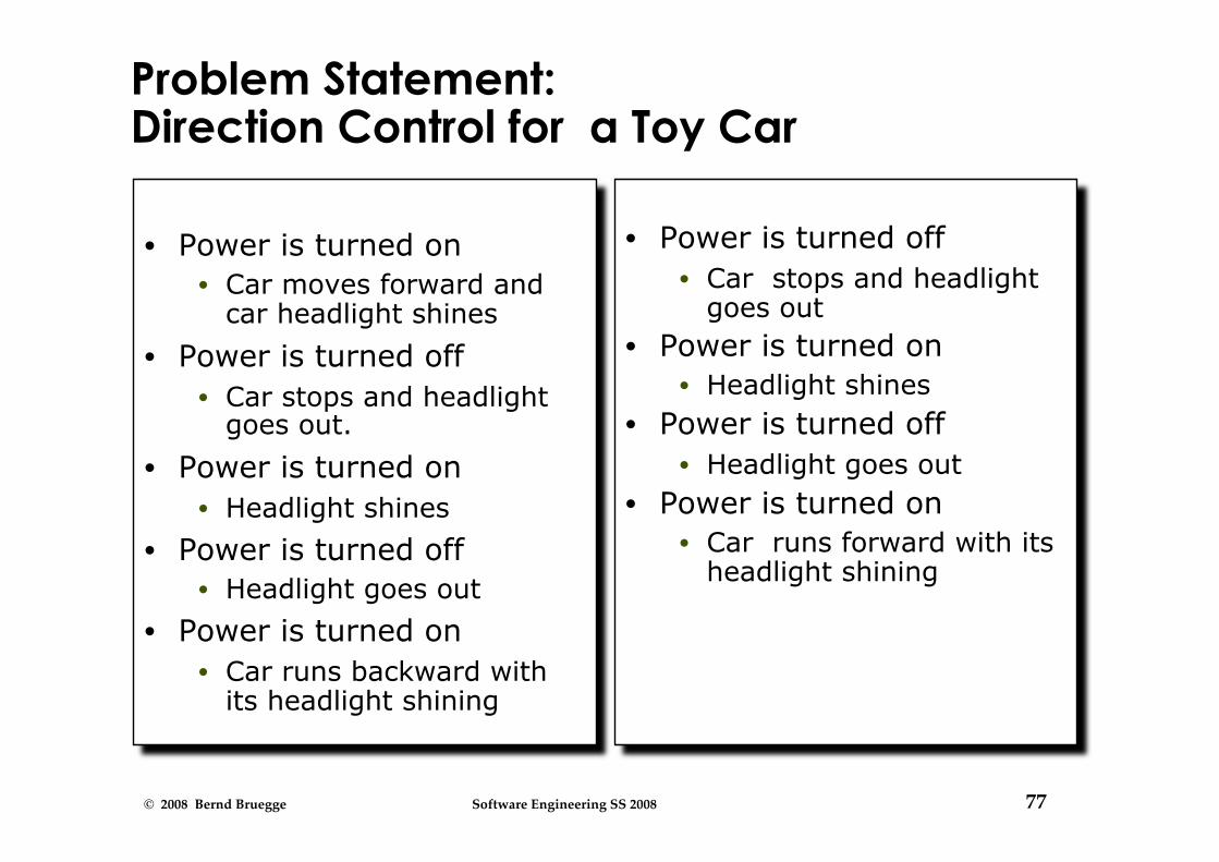
Problem Statement: Direction Control for a Toy Car
• Power is turned on • Car moves forward and
car headlight shines
• Power is turned off • Car stops and headlight
goes out.
• Power is turned on • Headlight shines
• Power is turned off • Headlight goes out
• Power is turned on • Car runs backward with
its headlight shining
• Power is turned off • Car stops and headlight
goes out • Power is turned on
• Headlight shines • Power is turned off
• Headlight goes out • Power is turned on
• Car runs forward with its headlight shining

78 © 2008 Bernd Bruegge Software Engineering SS 2008
Find the Functional Model: Use Cases
• Use case 1: System Initialization • Entry condition: Power is off, car is not moving • Flow of events:
1. Driver turns power on • Exit condition: Car moves forward, headlight is on
• Use case 2: Turn headlight off • Entry condition: Car moves forward with headlights on • Flow of events:
1. Driver turns power off, car stops and headlight goes out. 2. Driver turns power on, headlight shines and car does not
move. 3. Driver turns power off, headlight goes out
• Exit condition: Car does not move, headlight is out

79 © 2008 Bernd Bruegge Software Engineering SS 2008
Use Cases continued • Use case 3: Move car backward
• Entry condition: Car is stationary, headlights off • Flow of events:
1. Driver turns power on • Exit condition: Car moves backward, headlight on
• Use case 4: Stop backward moving car • Entry condition: Car moves backward, headlights on • Flow of events:
1. Driver turns power off, car stops, headlight goes out. 2. Power is turned on, headlight shines and car does not
move. 3. Power is turned off, headlight goes out.
• Exit condition: Car does not move, headlight is out

80 © 2008 Bernd Bruegge Software Engineering SS 2008
Use Cases Continued
• Use case 5: Move car forward • Entry condition: Car does not move, headlight is out • Flow of events
1. Driver turns power on • Exit condition:
• Car runs forward with its headlight shining

81 © 2008 Bernd Bruegge Software Engineering SS 2008
Use Case Pruning
• Do we need use case 5? • Let us compare use case 1 and use case 5:
Use case 1: System Initialization • Entry condition: Power is off, car is not moving • Flow of events:
1. Driver turns power on • Exit condition: Car moves forward, headlight is on
Use case 5: Move car forward • Entry condition: Car does not move, headlight is out • Flow of events
1. Driver turns power on • Exit condition:
• Car runs forward with its headlight shining

82 © 2008 Bernd Bruegge Software Engineering SS 2008
Dynamic Modeling: Create the Sequence Diagram
• Name: Drive Car • Sequence of events:
• Billy turns power on • Headlight goes on • Wheels starts moving forward • Wheels keeps moving forward • Billy turns power off • Headlight goes off • Wheels stops moving • . . .

83 © 2008 Bernd Bruegge Software Engineering SS 2008
Sequence Diagram for Drive Car Scenario
:Headlight Billy:Driver :Wheel
Power(on) Power(on)
Power(off) Power(off)
Power(on) Power(on)
Anything wrong with this sequence diagram?

84 © 2008 Bernd Bruegge Software Engineering SS 2008
Toy Car: Dynamic Model Wheel
Forward
Stationary
power on
Stationary
power off
Backward
power off
power on
Headlight
Off
On
power on power
off

85 © 2008 Bernd Bruegge Software Engineering SS 2008
Toy Car: Object Model
Car
Wheel
Motion: (For ward,
Stationary) Backward,
Star t_Moving() Stop_Moving()
Headlight
Status: (On, Off)
Switch_On() Switch_Off()
Power
Status: (On, Off)
TurnOn() TurnOff()

86 © 2008 Bernd Bruegge Software Engineering SS 2008
Examples for syntactical Problems
• Different spellings in different UML diagrams
• Omissions in diagrams

87 © 2008 Bernd Bruegge Software Engineering SS 2008
Is this a good Sequence Diagram?
Smart Card Onboard Computer Seat
Establish Connection Establish Connection
Accept Connection
Accept Connection
Get SeatPosition
“500,575,300”
The first column is not an actor
It is not clear where the boundary object is
It is not clear where the control object is

88 © 2008 Bernd Bruegge Software Engineering SS 2008
Backup Slides

89 © 2008 Bernd Bruegge Software Engineering SS 2008
Modeling in Action
• If it is a Face • What are its Attributes? • Sad, Happy
• Or is it a Mask? • Investigate the
functional model • Who is using it? -> Actors
• Art collector • Bankrobber • Carnival participant
• How is it used? -> Event flow
• “Napkin design” of a Mask to be used at the Venetian Carnival

90 © 2008 Bernd Bruegge Software Engineering SS 2008
Pieces of an Object Model
• Classes and their instances (“objects”) • Attributes • Operations • Associations between classes and objects

91 © 2008 Bernd Bruegge Software Engineering SS 2008
Associations
• Types of Associations • Canonical associations
• Part-of Hierarchy (Aggregation) • Kind-of Hierarchy (Inheritance)
• Generic associations

92 © 2008 Bernd Bruegge Software Engineering SS 2008
Attributes
• Detection of attributes is application specific • Attributes in one system can be classes in
another system • Turning attributes to classes and vice versa

93 © 2008 Bernd Bruegge Software Engineering SS 2008
Operations
• Source of operations • Use cases in the functional model • General world knowledge • Generic operations: Get/Set • Design Patterns • Application domain specific operations • Actions and activities in the dynamic model

94 © 2008 Bernd Bruegge Software Engineering SS 2008
Object vs Class
• Object (instance): Exactly one thing • This lecture on object modeling
• A class describes a group of objects with similar properties
• Game, Tournament, mechanic, car, database
• Object diagram: A graphical notation for modeling objects, classes and their relationships
• Class diagram: Template for describing many instances of data. Useful for taxonomies, patters, schemata...
• Instance diagram: A particular set of objects relating to each other. Useful for discussing scenarios, test cases and examples

95 © 2008 Bernd Bruegge Software Engineering SS 2008
Analysis model vs object design model (2)
• The analysis model is the basis for communication between analysts, application domain experts and end users.
• The object design model is the basis for communication between designers and implementors.