SOFTWARE DESIGN DESCRIPTION - … · musins-pro software design description ceng490 yağmur ertaŞ...
37
MUSINS-PRO SOFTWARE DESIGN DESCRIPTION CENG490 Yağmur ERTAŞ - 1819333 Duygu ABADAN - 1818863 Baler İLHAN - 1819853 Anıl ARPACI – 1818954 1/4/2015
Transcript of SOFTWARE DESIGN DESCRIPTION - … · musins-pro software design description ceng490 yağmur ertaŞ...

MUSINS-PRO
SOFTWARE DESIGN
DESCRIPTION CENG490
Yağmur ERTAŞ - 1819333 Duygu ABADAN - 1818863
Baler İLHAN - 1819853 Anıl ARPACI – 1818954
1/4/2015
MusicBox SDD 1.0 Jan 04, 2015
1
Table of Contents 1. Overview ................................................................................................................................................... 3
1.1 Scope ................................................................................................................................................... 3
1.2 Purpose ................................................................................................................................................ 3
1.3 Intended audience ............................................................................................................................... 3
1.4 References ........................................................................................................................................... 3
2. Definitions, Acronyms and Abbreviations ................................................................................................ 4
3. Conceptual Model for Software Design Descriptions .............................................................................. 6
3.1 Software Design in Context ................................................................................................................ 6
3.2 Software Design Descriptions within the Life Cycle .......................................................................... 6
3.2.1 Influences on SDD Preparation .................................................................................................... 6
3.2.2 Influences on Software Life Cycle Products ................................................................................ 7
3.2.3 Design Verification and Design Role in Validation .................................................................... 7
4. Design Description Information Content .................................................................................................. 7
4.1 Introduction ......................................................................................................................................... 7
4.2 SDD Identification .............................................................................................................................. 8
4.3 Design Stakeholders and Their Concerns ........................................................................................... 8
4.4 Design Views ...................................................................................................................................... 8
4.5 Design Viewpoints .............................................................................................................................. 8
4.6 Design Elements ............................................................................................................................... 10
4.7 Design Overlays ................................................................................................................................ 10
4.8 Design Rationale ............................................................................................................................... 10
4.9 Design Languages ............................................................................................................................. 10
5. Design Viewpoints .................................................................................................................................. 10
5.1 Introduction ....................................................................................................................................... 10
5.2 Context viewpoint ............................................................................................................................. 11
5.2.1 Design concerns ......................................................................................................................... 11
5.2.2 Design Elements ........................................................................................................................ 11
5.2.3 Example Languages ................................................................................................................... 13

MusicBox SDD 1.0 Jan 04, 2015
2
5.3 Composition Viewpoint .................................................................................................................... 13
5.3.1 Design Concerns ........................................................................................................................ 13
5.3.2 Design Elements ........................................................................................................................ 14
5.3.3 Example Languages ................................................................................................................... 16
5.4 Logical Viewpoint ............................................................................................................................ 16
5.4.1 Design Concerns ........................................................................................................................ 16
5.4.2 Design Elements ........................................................................................................................ 17
5.4.3 Example Languages ................................................................................................................... 28
5.5 Dependency Viewpoint ..................................................................................................................... 28
5.5.1 Design Concerns ........................................................................................................................ 28
5.5.2 Design elements ......................................................................................................................... 29
5.5.3 Example Languages ................................................................................................................... 29
5.6 Information Viewpoint ...................................................................................................................... 29
5.7 Patterns Use Viewpoint ..................................................................................................................... 29
5.8 Interface Viewpoint .......................................................................................................................... 29
5.8.1 Design Concerns ........................................................................................................................ 29
5.8.2 Design Elements ........................................................................................................................ 29
5.8.3 Example Languages ................................................................................................................... 31
5.9 Structure Viewpoint .......................................................................................................................... 31
5.9.1 Design Concerns ........................................................................................................................ 31
5.9.2 Design Elements ........................................................................................................................ 31
5.9.3 Example languages .................................................................................................................... 32
5.10 Interaction viewpoint ...................................................................................................................... 32
5.10.1 Design Concerns ...................................................................................................................... 32
5.10.2 Design Elements ...................................................................................................................... 32
5.10.3 Examples Languages................................................................................................................ 35
5.11 State Dynamics Viewpoint.............................................................................................................. 35
5.11.1 Design Concerns ...................................................................................................................... 35
5.11.2 Design elements ....................................................................................................................... 35
5.11.3 Example languages .................................................................................................................. 36

MusicBox SDD 1.0 Jan 04, 2015
3
1. Overview
1.1 Scope
The developed product is a system that can play musical instrument with just musical
notes. System will have options that loading image file or capturing image. Any proper image
file can be loaded to system for playing. With this property, the playing musical notes in a
musical instrument will be done with a very simple way. Objective of the system is to make
playing musical instrument easier for anybody who can interested in music. Each design concern
of the stakeholders are topic of at least one design view and these design views are described
with corresponding design elements and modeled with related UML diagrams. The document is
prepared in IEEE 1016-2009 standards.
1.2 Purpose
The purpose of this document is to provide a description of the design of the software
product to allow for software design to proceed with a perceptive of the design that is to be
structured and how the process of it develops. The topics of, general description of design
elements and their interactions, how the system will be structured, data & functional structure are
to be further discussed in order to help producing test cases, and help in maintenance services,
and also satisfy requirements, design details indicated in the SRS document.
1.3 Intended audience
Intended audience of software design description is all stakeholders which includes
people who are interested to music, development team and testers.
1.4 References
[1] IEEE. IEEE Std 1016-2009 IEEE Standard for Information Technology – System Design –
Software Design Descriptions. IEEE Computer Society, 2009
[2] StarUML 5.0 User Guide. (2005). Retrieved from http://staruml.sourceforge.net/docs/user-
guide (en)/toc.html
[3] Software Specification Requirements (SRS) Document of MusicBox prepared by MusIns-
Pro.

MusicBox SDD 1.0 Jan 04, 2015
4
2. Definitions, Acronyms and Abbreviations All the definitions, acronyms and abbreviations which are used in this document are described in
the following table.
Audiveris Open source code for OCR
Block diagram
A diagram showing in schematic form the general arrangement of the
parts or components of a complex system or process.
Class Diagram
A type of static structure diagram in UML that describes the structure of a
system by showing the system's classes, their attributes, operations (or
methods), and the relationships among the classes
DPI Dots Per Inch
IDE Integrated Development Environment
IEEE Standard International Electric Electronic Engineering Standards 1016-2009
JRE Java Runtime Environment
MP Megapixel
MusicXML An XML based file format for representing musical notation.
OCR Optical Character Recognition
Octave An interval between one musical pitch and another with half or double its
frequency.
OMR Optical Mark Recognition
PC Personal Computer
Rest An interval of silence in a piece of music, marked by a symbol indicating
the length of the pause.

MusicBox SDD 1.0 Jan 04, 2015
5
Score A written form of a musical composition.
Score Sheet A handwritten or printed for of music notation that uses musical symbols.
SDD Software Design Description
SDK Software Development Kit
Sprint A set of period of time during which specific work has to be completed
and made ready for review
SRS Software Requirement Specification
Stakeholders Any person with an interest in the system who is not a developer of the
system.
StarUML Design tool of diagrams
State Transition
Diagram
A type of static structure diagram in UML that describes the transition of
the system functions
USB Universal Serial Bus
Use Case
Diagram
A type of static structure diagram in UML that describes user's interaction
with the system
User Person who wants to use the system
User Interface An interface that our system contact with the user of the system. It gets all
needed information for its running, from user to our system.
XML Extensible Markup Language
.bmp Bitmap image file format
.mip Developer designed file format (MusIns-Pro)

MusicBox SDD 1.0 Jan 04, 2015
6
.tif, .tiff Tagged Image File Format
3. Conceptual Model for Software Design Descriptions
This section includes basic MusicBox System terms, concepts and context of SDD in
which the documentation is prepared. The purpose of conceptual model is to give a better
understanding of system terminology and software life cycle that the system resides on. The
conceptual model also gives information about stakeholders who will use SDD and how the SDD
will be used.
3.1 Software Design in Context
The MusicBox System will be designed as object-oriented in a modular design fashion.
The system will be implemented with Java using NetBeans as IDE. The system will try to give
the most accurate result in a most applicable, proper and correct time with its both software and
hardware parts; so it can respond to users’ wants correctly and quickly. It should respond
correctly in musical manner, also quickly in user interface and note recognition. The speed of
software part of the system depends on the computational operations according to processor(s) of
computer that runs our system.
Our MusicBox System is planned to be an application on the system in personal
computers which does not need to have an access to Internet. With its hardware component, the
MusicBox System will be a standalone application. Also with portability and adaptability, the
system can be ported to different platforms, such as Linux operating system, Raspberry Pi, etc.
3.2 Software Design Descriptions within the Life Cycle
This software will be created following IEEE standards. The primary milestones of this
system are requirements analysis, design description analysis, implementation and finally
verification and validation.
3.2.1 Influences on SDD Preparation
The very first influence on software design process is the MusicBox System SRS
document. In SDD, we considered the product perspective, functional/nonfunctional

MusicBox SDD 1.0 Jan 04, 2015
7
requirements and interface requirements that were included in the SRS. Given specifications and
the possible new requests from the stakeholders will specify the design process of this system.
3.2.2 Influences on Software Life Cycle Products
Firstly, all interfaces should be designed. Before connecting the software and hardware
parts of the system, user interface should be shown with sample examples, which are given and
processed using interface, to the stakeholders. As a result of this process, stakeholders can share
their ideas and requirements about the MusicBox System. Finally software and hardware parts
will be connected.
Furthermore, SDD will guide us all the way through the system. According to this
document or the first phase, some requirements can be added or removed from the software
requirements. Consequently, requirements of the stakeholders can be met more precisely after
each sprint of our development process.
3.2.3 Design Verification and Design Role in Validation
Verification is the process that we will test the MusicBox System whether it meets a set
of design specifications. In this process, we will look the SRS and SDD documents for
correctness of specifications. We will control that whether all functional and nonfunctional
requirements are correctly implemented according to the requirements of SRS and SDD
documents. Furthermore, we will control that whether the design viewpoints of the final
MusicBox System are met in the viewpoints part of the SDD document.
Validation is the process that the stakeholders and developers decide if the MusicBox
System is consistent with the main goal, which is reading musical notes, transferring their
information to Arduino board and playing them through Arduino board on musical instrument
(organ).
After the complete implementation of system, the testing process will be handled with
SDD influenced test plans and cases.
4. Design Description Information Content
4.1 Introduction
Software design description of MusicBox system analyzes how the system will be
designed and implemented. This section investigates these according to identification of the

MusicBox SDD 1.0 Jan 04, 2015
8
SDD, identified design stakeholders and design concerns, related design viewpoints, design
views, overlays, rationale and languages. Furthermore, this section includes design elements
which are design entities, attributes, relationships and constraints.
4.2 SDD Identification
MusicBox will be released by the middle of June 2015 after validation and verification
tests. Prototype of the system will be shown at beginning of January 2015. Modification and
distribution of MusicBox can only be done by copyright holder who is MusIns-Pro because of
the exclusive rights property.
Scope, references, context and summary can be found under the section “Overview”.
Glossary can be found under the section “Definitions, Acronyms and Abbreviations”.
4.3 Design Stakeholders and Their Concerns
Stakeholders comprise a developer team which is MusIns-Pro at the Middle East
Technical University Department of Computer Engineering members. Mainly concerns of the
stakeholders are quality of the photo which loads to the system because it must have high
quality. In addition, this project may cost a little expensive.
4.4 Design Views
Design views helps design stakeholders about focusing on design details from a specific
perspective and meeting relevant requirements. Each identified design concern must be topic of
at least one design view so that SDD is complete. Each design concerns identified in the previous
subsection is the topic of most of the design views in this document; thus, this SDD is completed.
For example, concerns about cost are topic of composition view. Moreover, concerns about
quality of photo are topic of logical view. In this document, context, composition, logical,
dependency, information, patterns use, interface, interaction and state dynamics views will be
explained in section 4.5 as their corresponding viewpoints. For some views, relevant UML
diagrams will be shown in order to clarification.
4.5 Design Viewpoints
This document describes context, composition, logical, dependency, information, patterns
use, interface, structure, and interaction and state dynamics viewpoints.

MusicBox SDD 1.0 Jan 04, 2015
9
Context Viewpoint: It describes the relationships, dependencies and interactions between the
system and its environment such as users and other interacting stakeholders. Interactions
between the system and its actors are very intense, hence concerns of this viewpoint is important
and suitable for MusicBox. It includes use case, context and block diagram showing the system
boundary.
Composition Viewpoint: It describes how the design subject split up into its components and
which roles these components have. It can be used in estimating cost, staffing and scheduling
duties of development team. It includes a deployment and component diagram.
Logical Viewpoint: It describes class structures, interactions between them and how they are
designed and implemented. Also it supports development and reuse of existing logical
components. It includes a class diagram which defines objects and classes, and relationships
between them.
Dependency Viewpoint: It describes the components of the system and dependencies between
these components. It gives information about shared information and order of execution of these
components.
Information Viewpoint: It describes data items, data types and classes, data stores and access
mechanisms. It gives information about data attributes.
Patterns Use Viewpoint: It describes design patterns and usage of design patterns which meet
design ideas of the project.
Interface Viewpoint: It describes the details of external and internal interfaces. It provides
information to the designers, programmers and testers before proceeding with the detailed design
of the system. This also provides designers, programmers and testers to use the system as a
random user.
Interaction Viewpoint: It describes the sequence of actions and how, why, where and at what
level actions occur in the system. It is preferred to use state dynamics views in detailed for this
project.
State Dynamics Viewpoint: It describes the internal behavior of the system. System dynamics
include modes, states, transitions and reactions to events. It gives information step by step about
the system operation. It includes state machine diagram which defines conditions, states,
transitions and relationships between them.

MusicBox SDD 1.0 Jan 04, 2015
10
4.6 Design Elements
Any item which appears in a design view is named as design elements. It may be one or
some of these subcases; design entity, design relationship, design attribute and design
constraints. All design elements are defined with subcases under their corresponding viewpoint
in section 5 of the software design description.
4.7 Design Overlays
Design overlays usually used to add information to the existing views. This concept will
be explained clearly when necessary in the design viewpoints section which is 5.
4.8 Design Rationale
Object-Oriented approach was chosen while designing because by this way hardware part
and software part will be combined easily. Software part includes parsing and reading notes and
transmitting data. To design these lots of package were used. These packages are connected
between each other and they can be controlled separately. Furthermore, for hardware part a
package was used and there is another package to combine software and hardware parts.
4.9 Design Languages
In this document Unified Modeling Language (UML) will be used as the modeling
language for the diagrams. The modeling language is used for emphasizing the static structure
and dynamic behavior of the system.
5. Design Viewpoints
5.1 Introduction
This section provides several main design viewpoints of MusicBox with their
corresponding design concerns and appropriate design languages. Respectively, context,
composition, logical, dependency, information, patterns, interface, structure and interaction
viewpoints are defined in the following subsections. Short descriptions relating a minimal set of
design entities, design relationships, design entity attribute, and design constraints are provided
for each viewpoint.
MusicBox SDD 1.0 Jan 04, 2015
11
5.2 Context viewpoint
The context viewpoint of MusicBox software shows the functions provided by a design
subject with reference to an explicit context. The services are the functions, which describes the
relationships, dependencies, and interactions between the system and its environment like users
and other stakeholders.
5.2.1 Design concerns
Design concerns consist of services, actors and system boundaries. MusicBox is formed
of the interface and the hardware equipment; there is only one type actor which uses the system.
Therefore, there is no constraint according to users. The services and the system boundaries are
established according to the musical instrument organ.
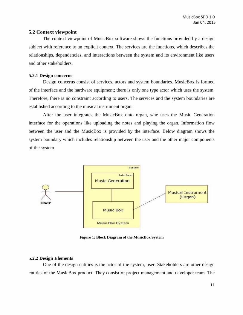
After the user integrates the MusicBox onto organ, s/he uses the Music Generation
interface for the operations like uploading the notes and playing the organ. Information flow
between the user and the MusicBox is provided by the interface. Below diagram shows the
system boundary which includes relationship between the user and the other major components
of the system.
Figure 1: Block Diagram of the MusicBox System
5.2.2 Design Elements
One of the design entities is the actor of the system, user. Stakeholders are other design
entities of the MusicBox product. They consist of project management and developer team. The

MusicBox SDD 1.0 Jan 04, 2015
12
last design entity is the musical instrument, organ. Below diagram shows the design relationship
which includes provided input and received output between the user and the other major
components of the system.
Figure 2: Context Diagram of the MusicBox System
Figure 3 given below describes system interaction and functionality with the user. There
is only one type user which uses all the functionalities related to the system. These functionalities
are setting up the product onto the musical instrument, capturing and uploading the picture,
loading and saving the music file, uploading the MusicXML file, converting the notes, playing,
replaying and stopping the music.

MusicBox SDD 1.0 Jan 04, 2015
13
Figure 3: Use Case Diagram of the MusicBox System
5.2.3 Example Languages
The diagrams given in the previous subsections are created by the UML. One of these
diagrams is the block diagram describing interrelationships of a system. Other one is the context
diagram defining the boundary between the system and its environment. The last one of them is
the use case diagram showing user interactions with the system.
5.3 Composition Viewpoint
The purpose of the composition viewpoint of Recommendation System is to define the
system as a composition of its subsystems. The project is formed by 4 main submodules: “OCR”,
“Parser”, “MusicBox” and “UserInterface”. Detailed explanation about the relations between
these modules will be explained in coming sections.
5.3.1 Design Concerns
With the help of information in composition viewpoint, system stakeholders and
developer team can plan and control the software product. The design of this project is structured
into sub-modules and components such as interface and other packages. The project is managed
by planning, monitoring and controlling these components. All acquired information about
project provides to estimate cost, staffing, and schedule for the development effort.

MusicBox SDD 1.0 Jan 04, 2015
14
Below UML deployment diagram shows run-time (physical) decomposition of the
system.
Figure 4: Deployment Diagram of the MusicBox System
5.3.2 Design Elements
The project is formed of interface and classes inside packages as design entities. There
are two there level packages which are “Parser”, “MusicBox” and “UserInterface” which allow
the system to be run as application.
MusicBox package consist of subclasses named “connection” and
“mainMotorController”.
Parser package consist of subclasses which are used for store note information and
convert musicXML file into desired type (.mip file).
User Interface package consist of user interface and it is actions. It performs connection
between other packages via user actions.
Detailed explanation about the relations between these modules is given below:

MusicBox SDD 1.0 Jan 04, 2015
15
Figure 5: Component Diagram of the MusicBox System
5.3.2.1 Function Attribute
In Parser package, the class “MusicXMLParser” parses given musicXML file and stores
information inside the “Note” vector which is designed to store note information. “Main” class
performs connection between “OCR” sub system and the parser. Also it converts note array to
format that Arduino needs.
Inside the musicBox package, the class “Connection” provides connection between user
interface and the motor controller. Data is provided Arduino serially and in order to send data
from the parser synchronously, “jscc” library is used. “MainMotorController” class controls note
servo motor interactions.
User Interface package consist of GUI class which formed of .ui file consists layout of
interface and “Actions” class which consists of actions provided by the interface.

MusicBox SDD 1.0 Jan 04, 2015
16
5.3.2.2 Subordinates Attribute
GUI consists of view and controller components. The view component defines and
manages how the data is presented to the user. The controller component manages user
interaction and passes these interactions to the view and model.
MusicBox consists of motor and its controller components. It controls motors and
manages connection between the systems.
Application Server consists of all the software part of the project. It has OCR and Parser
components which perform reading notes and prepare for the MusicBox.
5.3.3 Example Languages
A component diagram showing functional (logical) decomposition of the system and a
deployment diagram showing run-time (physical) decomposition of the system have given in the
previous sections by using UML modeling language.
5.4 Logical Viewpoint
The purpose of the Logical viewpoint is to elaborate existing and designed types and their
implementations as classes and interfaces with their structural static relationships. For each
entity, there will be a diagram to overview the entity and then a table that name, return type;
visibility of the entity/class diagram is shown in. Also, definition of each element is provided.
After all elements are explained, the class diagram that shows relationships between the classes
is drawn.
5.4.1 Design Concerns
The logical viewpoint is employed to show the development and reuse of abstractions
and their implementations. This means, object oriented programming simplifies to maintain and
modify existing code while new objects are created. Since identifying object classes is often
difficult part of object oriented design, during the implementation phase of the project there can
be some changes in object identification.
MusicBox SDD 1.0 Jan 04, 2015
17
5.4.2 Design Elements
The project has one sub-system named OCR, three packages named ‘parser’, ‘musicBox’
and ‘UserInterface’. All packages have total nine classes named ‘Note’, ‘MusicXMLParser’,
‘VoiceDef’, ‘XMLPart’, ‘Main’ from ‘parser’; ‘Connection and ‘MainMotorController’ from
‘musicBox’; ‘UserActions’ and ‘MainGui’ from ‘UserInterface’. All package connections can be
seen in ‘Class Diagram of the MusicBox System’, in Figure 6.

MusicBox SDD 1.0 Jan 04, 2015
18
Figure 6: Class Diagram of the MusicBox System

MusicBox SDD 1.0 Jan 04, 2015
19
5.4.2.1 VoiceDef Class
This class will be defined in the software part of the project. It will be used during
parsing musicXML file from other classes like “MusicXMLParser”. Main purpose of this class is
to form musicString structure which will be a combination of part and voice.
Diagram:
Description:
Name
Type/Return
Value Type
Visibility Definition
part int private This variable refers part value of the
musicString.
voice int private This variable refers to voice value of the
musicString.
5.4.2.2 Note Class
This class will be defined in the software part of the project. The purpose of Note class is
keeping information about each note of the song which is contained by musicXML file.

MusicBox SDD 1.0 Jan 04, 2015
20
Diagram:
Description:
Name Type/Return
Value Type
Visibility Definition
value byte public This value refers the numeric value of the
note.
duration byte public This value refers to duration the duration of
the note, as milliseconds.
rest boolean public This value indicates whether this note is
rest.
type byte public This value indicates the type of the note.
getStringForNote String public
static
This function returns a MusicString
representation of the note value and
duration which indicates a note and an
octave.

MusicBox SDD 1.0 Jan 04, 2015
21
5.4.2.3 XMLPart Class
This class is used as helper class for the MusicXMLParser class. It will be defined in the
software part of the project. A musical notes can store multiple instruments however this project
only interest with the organ. This class contains part information of the instrument.
Diagram:
Description:
Name Type / Return
Value Type
Visibility
Definition
ID string public This value refers the id of the part.
part_name string public This value refers the name of the part.
XMLPart void public This function is the constructor of the class
which sets empty values as default.
5.4.2.4 MusicXMLParser Class
This class will be defined in the software part of the project. It can be seen as primary
class of the software package which uses all other classes and performs operations like parsing
musicXML file and storing all notes’ information in the designed class.

MusicBox SDD 1.0 Jan 04, 2015
22
Diagram:
Description:
Name Type/Return
Value Type
Visibility Definition
xomBuilder Builder private
This value responsible for creating XOM
Document objects file by reading an XML
document
xomDoc
Document
private
This value represents a complete XML
document including its root element and
others
volumes String[0..*] private This value is volume of the song.
tempo
int
public
This value refers to tempo of the current
song. It is measured in “pulses per quarter".
The parser uses this value to convert note
durations, which are relative values and not
directly related to time measurements, into
actual times.

MusicBox SDD 1.0 Jan 04, 2015
23
noteArr
Note[0..*]
public
This array stores whole notes of the current
song for later usage. Note is a structure
which is defined by developer.
MusicXMLParser()
void
public
This function is the constructor of the given
class. It will initialize the default values.
parse()
void
public
This function will be responsible for
starting parsing musicXML file. It will be
called via filename.
parse()
void
public
Thisfunction will be responsible for starting
parsing musicXML file. It overrides parse
function with no parameters.
parsePart()
void
public
This function will be responsible for
parsing one part. It can be called via three
parameters which are, entire part of the
music and an array of XMLpart classes that
contains instrument information of the part
parsePartHeader()
void
public
This function is responsible for parsing an
element in the part- list. It can be called
with an element and an array of XMLpart
classes which contains partlist elements
parseNote() void public This function is responsible for parsing
MusicXML note Element. It can be called
with the note Element . Finally it creates
Note object and after storing all information
MusicBox SDD 1.0 Jan 04, 2015
24
in it, pushes it to Note array for later step.
createMusicFile()
File public This function is responsible for creating a
new file for Arduino.
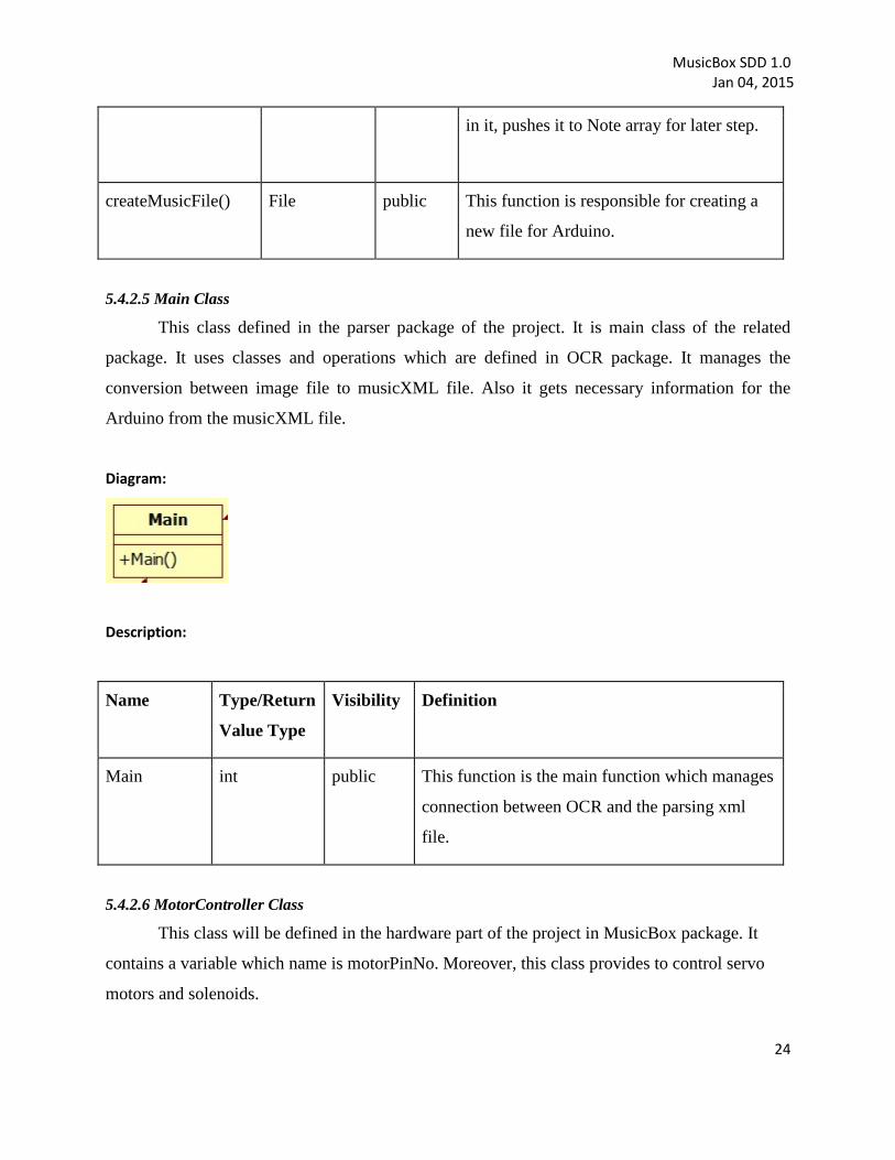
5.4.2.5 Main Class
This class defined in the parser package of the project. It is main class of the related
package. It uses classes and operations which are defined in OCR package. It manages the
conversion between image file to musicXML file. Also it gets necessary information for the
Arduino from the musicXML file.
Diagram:
Description:
Name Type/Return
Value Type
Visibility Definition
Main
int
public
This function is the main function which manages
connection between OCR and the parsing xml
file.
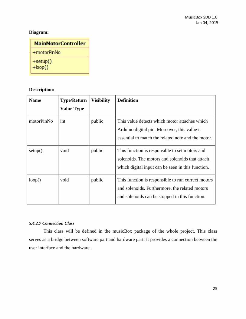
5.4.2.6 MotorController Class
This class will be defined in the hardware part of the project in MusicBox package. It
contains a variable which name is motorPinNo. Moreover, this class provides to control servo
motors and solenoids.
MusicBox SDD 1.0 Jan 04, 2015
25
Diagram:
Description:
Name Type/Return
Value Type
Visibility Definition
motorPinNo
int
public
This value detects which motor attaches which
Arduino digital pin. Moreover, this value is
essential to match the related note and the motor.
setup()
void
public
This function is responsible to set motors and
solenoids. The motors and solenoids that attach
which digital input can be seen in this function.
loop()
void
public
This function is responsible to run correct motors
and solenoids. Furthermore, the related motors
and solenoids can be stopped in this function.
5.4.2.7 Connection Class
This class will be defined in the musicBox package of the whole project. This class
serves as a bridge between software part and hardware part. It provides a connection between the
user interface and the hardware.

MusicBox SDD 1.0 Jan 04, 2015
26
Diagram:
Description:
Name
Type / Return
Value Type
Visibility Definition
connection()
void
public
This function is responsible for the
connection task between user interface and
hardware part.
sendData()
void
public
This function is responsible for the data
sending to microcontroller which is provided
by the Parser and the OCR packages.
5.4.2.8 UserActions Class
This class is defined in the user interface package of the project. It performs user actions
performed via user interface and provides connection between hardware part and software part of
the project.
Diagram:

MusicBox SDD 1.0 Jan 04, 2015
27
Description:
Name
Type / Return
Value Type
Visibility Definition
upload()
void
public
This function performs uploading
musicXML file, image file or “.mip” file to
the project.
convert()
void
public
This function performs conversion operation
from the uploaded file to “.mip” format.
saveAs() void public This function is responsible for the saving
note information into .mip format from
given file.
capture() void public This function provides user the capture
picture via user interace
play() void public This function is responsible for making
organ play music with data which is read
from file.
stop() void public This function provides user to stop music
while musicBox playing.
5.4.2.9 MainGui Class
This class will be defined in the musicBox package of the whole project. This class is
responsible for providing layout information of the user interface. (It is given as .ui format)
Diagram:

MusicBox SDD 1.0 Jan 04, 2015
28
Description:
Since it is implemented as ‘.ui’ format there is not any attribute or operation defined by
the developer.
5.4.2.10 OCR Sub-System
OCR is a subsystem which consists of all the Audiveris source code (optical music
recognition).
Diagram:
Description:
This system has many packages and classes inside and since it is not designed by the
developer, they are not indicated in the given diagram above.
5.4.3 Example Languages
A class diagram which describes the structure of a system by showing classes of the
system has given in the previous sections by using UML modeling language.
5.5 Dependency Viewpoint
The Dependency viewpoint specifies the relationships of interconnection and access
among entities. These relationships include shared information, order of execution, or
parameterization of interfaces.
5.5.1 Design Concerns
Dependency viewpoint helps maintainers to isolate entities causing system failures or
resource bottlenecks. In producing the system integration plan, the system is identified with the
sub-modules and the components which are dependent to each other.

MusicBox SDD 1.0 Jan 04, 2015
29
5.5.2 Design elements
The product is composed of the user interface and classes inside packages as design
entities. Detailed explanation about the dependency between the entities and the modules are
explained with the component and deployment diagrams in the section 5.3.2.
5.5.2.1 Dependencies Attribute
A description of the relationships among the entities is explained in section 5.3.2.1.
5.5.3 Example Languages
The component diagram showing functional (logical) decomposition of the system in the
section 5.3.2 and the package diagram depicting the dependencies between the packages in the
section 5.9.2 are created by UML.
5.6 Information Viewpoint
This section is not required for our project.
5.7 Patterns Use Viewpoint
This section is not required for our project.
5.8 Interface Viewpoint
In this part of document, the details of external and internal interfaces will be defined.
There shall be two interfaces in MusicBox System, which are System-Parser Interface and
System-Arduino Interface. Also there is one user interface in our system.
All communication related to Arduino board will be established via USB.
5.8.1 Design Concerns
Interface viewpoint provides information to the designers, developers and testers before
proceeding with the detailed design of the system. It also informs them about how cooperating
entities will interact. With the ease of each interface descriptions, designers and developers can
know internal and external connections of system to develop it. This contributes ease of
maintenance.
5.8.2 Design Elements
In this subsection, user interface of MusicBox System is shown. In addition, usage of
these interfaces is given in details.

MusicBox SDD 1.0 Jan 04, 2015
30
Figure 7: User Interface of MusicBox
Figure 7 shows the only interface of the MusicBox System. This interface firstly provides
users to load a file capture an image or save as any transition format (such as .xml and .mip) of
program. If user load a file, the path of loaded file is shown in ‘File:’ line. If user chooses
‘Capture an Image’ button, the captured image is saved on path of MusicBox program
executable. Then the path of captured image is shown on ‘File:’ line of user interface. If user
chooses ‘Save as’ button, user can save any transition formats of MusicBox system. These
formats are .xml, .mxl and .mip. ‘Convert’ button of user interface makes all transitions about
playing musical notes and prepares the last format, which is .mip, for sending it to Arduino.
When ‘Convert’ button is pressed, ‘Processing’ progress bar of user interface starts progressing.
Its reaching to 100% means that the musical notes are ready to play. These all conversion
operations from image to .mip file are done by System-Parser Interface, which is explained
precisely in Section 5.3 and Section 5.4 of this SDD document.
After all conversion operations, user can simply play and stop from ‘Mini Music Box
Player’ part of user interface. There are two buttons named ‘Play’ and ‘Stop’, which handles
playing and stopping operations of MusicBox System. These playing and stopping operations are
done by System-Arduino Interface, which is explained precisely in Section 5.3 and 5.4 of this
SDD document.
MusicBox SDD 1.0 Jan 04, 2015
31
In the ‘Logs:’ part of user interface, developers mainly gives information about usage of
program to the user. Errors and warnings are also given from here to the user. An error is a
significant problem, such as wrong file type. A warning is not a necessarily significant, but might
indicate a possible future problem, such as low image resolution. Information describes the
wanted steps and the successful operations of a MusicBox System.
5.8.3 Example Languages
All necessary UML component diagrams have given in the previous sections of this SDD
document.
5.9 Structure Viewpoint
5.9.1 Design Concerns
Structure viewpoint informs user and the developer about the interaction between the
packages in the system.
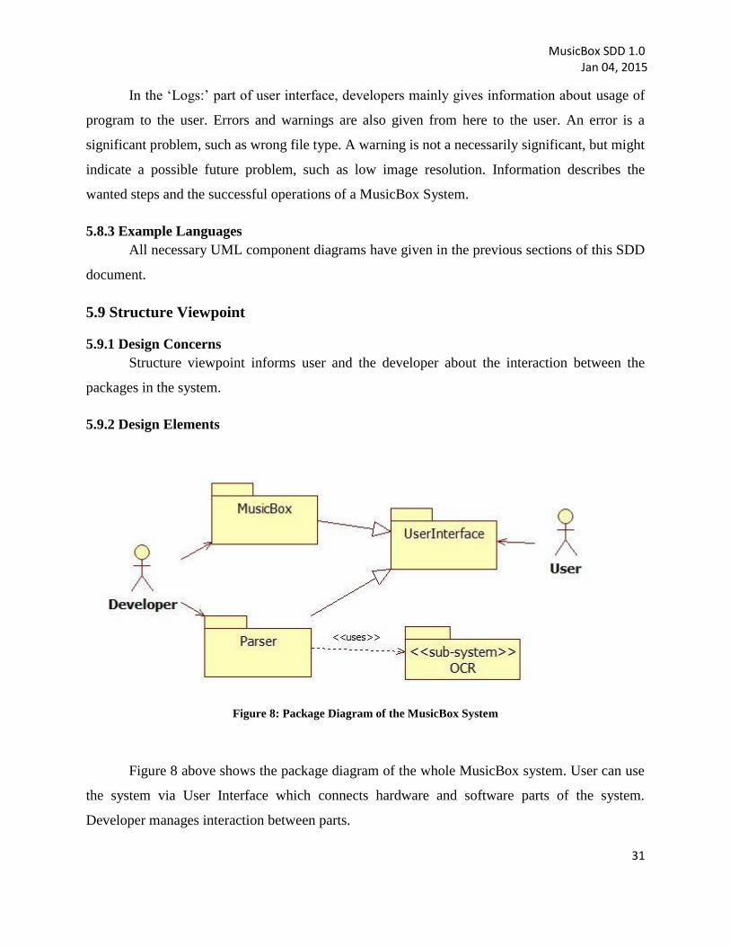
5.9.2 Design Elements
Figure 8: Package Diagram of the MusicBox System
Figure 8 above shows the package diagram of the whole MusicBox system. User can use
the system via User Interface which connects hardware and software parts of the system.
Developer manages interaction between parts.
MusicBox SDD 1.0 Jan 04, 2015
32
Detailed component diagram is given in section 5.3 and class diagram given in section
5.4.
5.9.3 Example languages
UML package diagram showing interaction between the parts of the system and the user
has given in the previous sections by using UML modeling language.
5.10 Interaction viewpoint
In this section, main functionalities of the system are given by the help of sequence
diagrams. Moreover, it defines strategies for interaction among entities.
5.10.1 Design Concerns
For designers, this section includes evaluating allocation of responsibilities in
collaborations and description of interactions in terms of messages among affected objects in
fulfilling required actions with the help of sequence diagrams.
5.10.2 Design Elements
Given sub-sections below, user and system interactions are illustrated.
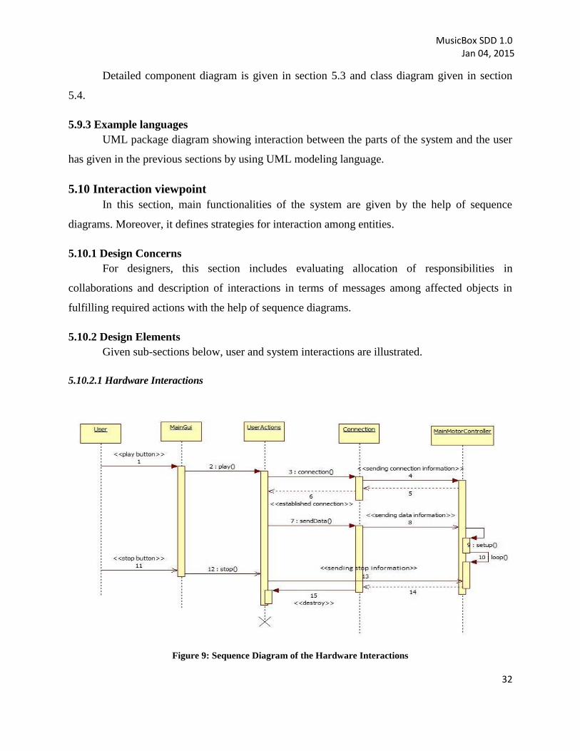
5.10.2.1 Hardware Interactions
Figure 9: Sequence Diagram of the Hardware Interactions
MusicBox SDD 1.0 Jan 04, 2015
33
Above sequence diagram is related to play and stop functionality. For playing the music,
user should click “play” button that is seen in “MainGUI”. It triggers play function of the
“UserActions”. Firstly, connection is established between the “Connection” object and
“MainMotorController”. Then, data is sent to “MainMotorController”. In
“MainMotorController”, after setup function is called, loop function executes and motors begin
to motion. If the user presses the stop button in the user interface while lasting loop, stop
function of the “UserActions” is triggered and stop information is sent to
“MainMotorController”. This process provides to return of sendData function and the music
stops.
5.10.2.2 Software and Parser Interactions
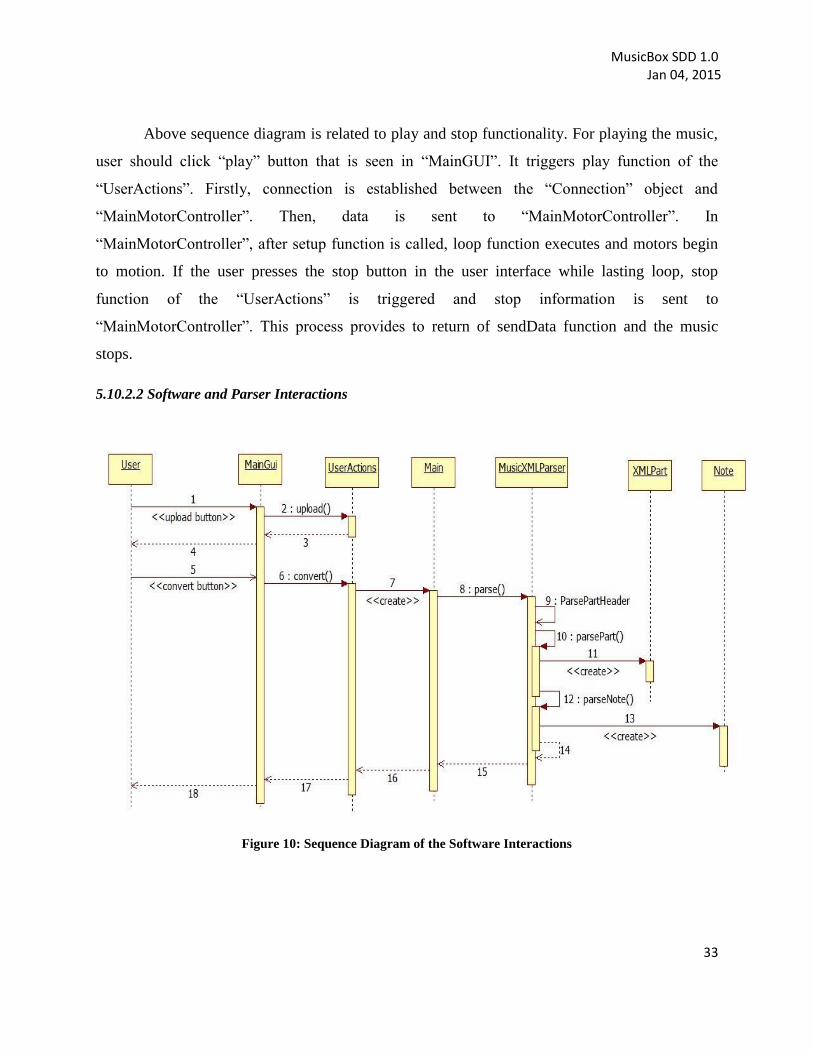
Figure 10: Sequence Diagram of the Software Interactions

MusicBox SDD 1.0 Jan 04, 2015
34
Given sequence diagram above shows the user and system interaction related with the
upload and the convert button in the user interface. Upload functionality can be used by the user
via user interface. This provides user to upload musicXML file, image file or previously
generated “.mip” file.
Convert button can be reached via button inside the user interface. When user clicked to
button, it triggers convert functionality in the “UserActions” class. This functionality provides
conversion to “.mip” format from the uploaded file. For example, if it is an image file, it first
converts file to musicXML file and then parses this output into “.mip” format. If it is a
musicXML file, it directly parses it to “.mip” format. Also final output namely “.mip” format is
stored in the main object in the parser package.
5.10.2.3 GUI Interactions
Figure 11: Sequence Diagram of the Software and GUI Interactions
Given sequence diagram above shows the “capture” and “saveAs” actions in the user
interface. “saveAs” button provides user to save converted file namely “.mip file” into desired

MusicBox SDD 1.0 Jan 04, 2015
35
format like “musicXML” or “.mip” file into the personal computer for later usage. Stored file
can be used later to play music via application.
“Capture” button provides user to take picture via user interface by the help of connected
camera. Captured image is directly used by the OCR and the Parser and it makes ready image
5.10.3 Examples Languages
Sequence diagrams which show how processes operate with one another and in what
order has given in the previous section by using UML modeling language.
5.11 State Dynamics Viewpoint
In this section, system behavior and states of the system are given via the state transition
diagram.
5.11.1 Design Concerns
Designers, developers and testers are informed about dynamic view of the system which
includes modes, states, transitions and reactions to events.
5.11.2 Design elements
MusicBox system software has five states named “ConnectionState”, “PictureState”,
“musicXML”, “Note” and “.mip file” as shown in the Figure Z. “ConnectionState” is the first
state to connect to the product. After “ConnectionState”, the next state can be “PictureState”,
“musicXML” or “Note” depending upon uploading a picture or a musicXML file or loading
“.mip file”. If next state is “PictureState”, the notes in the picture are converted musicXML file
and transferred to “musicXML” state. If next state is “musicXML”, the notes in the musicXML
file is read and transferred to the “Note” state. After “Note” state, notes are converted to .mip file
and music can be played. If the music is stopped, return the “Connection State”. When the
product is disconnected, it stays on end state.

MusicBox SDD 1.0 Jan 04, 2015
36
Figure 12: State Machine Diagram of the MusicBox System
5.11.3 Example languages
State machine diagram given in the previous section which shows the internal behavior of
the system by state transitions is created by the UML.