Software Defined Batteries - ACM...
15
Software Defined Batteries Anirudh Badam 1 , Ranveer Chandra 1 , Jon Dutra 1 , Anthony Ferrese 2 , Steve Hodges 1 , Pan Hu 3 , Julia Meinershagen 1 , Thomas Moscibroda 1 , Bodhi Priyantha 1 , Evangelia Skiani 4 1 Microsoft Corporation, 2 Tesla Motors, 3 University of Massachusetts Amherst, 4 Columbia University Abstract Different battery chemistries perform better on different axes, such as energy density, cost, peak power, recharge time, longevity, and efficiency. Mobile system designers are constrained by existing technology, and are forced to se- lect a single chemistry that best meets their diverse needs, thereby compromising other desirable features. In this paper, we present a new hardware-software system, called Software Defined Battery (SDB), which allows system designers to in- tegrate batteries of different chemistries. SDB exposes APIs to the operating system which control the amount of charge flowing in and out of each battery, enabling it to dynam- ically trade one battery property for another depending on application and/or user needs. Using microbenchmarks from our prototype SDB implementation, and through detailed simulations, we demonstrate that it is possible to combine batteries which individually excel along different axes to de- liver an enhanced collective performance when compared to traditional battery packs. 1. Introduction The utility of a mobile device is often constrained by the ca- pabilities of its battery. Whilst integrated circuit performance has doubled every eighteen months according to Moore’s law, the same is far from true for battery technology. Bat- tery performance can be evaluated in many different ways (see Table 1), but no matter which metric we look at, it has taken more than a decade to double performance. Furthermore, the various properties of batteries are often at odds with each other. For example, batteries with higher power densities tend to have lower volumetric and gravimet- ric energy densities, and vice versa. Similarly, making a con- formable battery that fits a particular industrial design com- promises its performance characteristics. Permission to make digital or hard copies of all or part of this work for personal or classroom use is granted without fee provided that copies are not made or distributed for profit or commercial advantage and that copies bear this notice and the full citation on the first page. Copyrights for components of this work owned by others than the author(s) must be honored. Abstracting with credit is permitted. To copy otherwise, or republish, to post on servers or to redistribute to lists, requires prior specific permission and/or a fee. Request permissions from [email protected]. SOSP’15, October 4–7, 2015, Monterey, CA. Copyright is held by the owner/author(s). Publication rights licensed to ACM. ACM 978-1-4503-3834-9/15/10. . . $15.00. http://dx.doi.org/10.1145/2815400.2815429 Battery Characteristic Units Energy capacity joule Volume mm 3 Mass kilogram Discharge rate watt Recharge rate watt Gravimetric energy density joule / kilogram Volumetric energy density joule / liter Cost $ / joule Discharge power density watt / kilogram Recharge power density watt / kilogram Cycle count Number of dis- charge/recharge cycles Longevity % of original capacity after N cycles Internal resistance ohm Efficiency % of energy turned into heat Bend radius mm Table 1. A number of battery characteristics. These are of- ten in tension with each other – for example increasing recharge rate compromises longevity. Such tradeoffs are present even within a given physical battery. For example, energy delivered by a battery in a sin- gle charge-discharge cycle (energy capacity) is inversely re- lated to the rate at which the battery is drained (discharge rate). This is because the resistance losses inside a battery are proportional to the square of the current. Similarly, a bat- tery’s longevity – its ability to perform consistently follow- ing many charge-discharge cycles – is inversely related to the discharge and recharge rates. This is because higher cur- rents speed up the creation of fissures in the electrodes that reduce the amount of energy a battery can store. In summary, no single battery type can deliver the ever- growing list of requirements of modern devices: fast charg- ing, high capacity, low cost, less volume, light in weight, less heating, better longevity, and high peak discharge rates. A growing range of battery chemistries are under devel- opment, each of which delivers a different set of benefits in terms of performance. We believe that combining multi- ple of these heterogeneous batteries instead of using a single battery chemistry can allow a mobile system to dynamically 215
Transcript of Software Defined Batteries - ACM...
Software Defined Batteries
Anirudh Badam1, Ranveer Chandra1, Jon Dutra1, Anthony Ferrese2, Steve Hodges1, Pan Hu3,Julia Meinershagen1, Thomas Moscibroda1, Bodhi Priyantha1, Evangelia Skiani4
1Microsoft Corporation, 2Tesla Motors, 3University of Massachusetts Amherst, 4Columbia University
AbstractDifferent battery chemistries perform better on different
axes, such as energy density, cost, peak power, recharge
time, longevity, and efficiency. Mobile system designers are
constrained by existing technology, and are forced to se-
lect a single chemistry that best meets their diverse needs,
thereby compromising other desirable features. In this paper,
we present a new hardware-software system, called Software
Defined Battery (SDB), which allows system designers to in-
tegrate batteries of different chemistries. SDB exposes APIs
to the operating system which control the amount of charge
flowing in and out of each battery, enabling it to dynam-
ically trade one battery property for another depending on
application and/or user needs. Using microbenchmarks from
our prototype SDB implementation, and through detailed
simulations, we demonstrate that it is possible to combine
batteries which individually excel along different axes to de-
liver an enhanced collective performance when compared to
traditional battery packs.
1. IntroductionThe utility of a mobile device is often constrained by the ca-
pabilities of its battery. Whilst integrated circuit performance
has doubled every eighteen months according to Moore’s
law, the same is far from true for battery technology. Bat-
tery performance can be evaluated in many different ways
(see Table 1), but no matter which metric we look at, it has
taken more than a decade to double performance.
Furthermore, the various properties of batteries are often
at odds with each other. For example, batteries with higher
power densities tend to have lower volumetric and gravimet-
ric energy densities, and vice versa. Similarly, making a con-
formable battery that fits a particular industrial design com-
promises its performance characteristics.
Permission to make digital or hard copies of all or part of this work for personal orclassroom use is granted without fee provided that copies are not made or distributedfor profit or commercial advantage and that copies bear this notice and the full citationon the first page. Copyrights for components of this work owned by others than theauthor(s) must be honored. Abstracting with credit is permitted. To copy otherwise, orrepublish, to post on servers or to redistribute to lists, requires prior specific permissionand/or a fee. Request permissions from [email protected].
SOSP’15, October 4–7, 2015, Monterey, CA.Copyright is held by the owner/author(s). Publication rights licensed to ACM.ACM 978-1-4503-3834-9/15/10. . . $15.00.http://dx.doi.org/10.1145/2815400.2815429
Battery Characteristic UnitsEnergy capacity joule
Volume mm3
Mass kilogram
Discharge rate watt
Recharge rate watt
Gravimetric energy density joule / kilogram
Volumetric energy density joule / liter
Cost $ / joule
Discharge power density watt / kilogram
Recharge power density watt / kilogram
Cycle count Number of dis-
charge/recharge cycles
Longevity % of original capacity after
N cycles
Internal resistance ohm
Efficiency % of energy turned into
heat
Bend radius mm
Table 1. A number of battery characteristics. These are of-
ten in tension with each other – for example increasing
recharge rate compromises longevity.
Such tradeoffs are present even within a given physical
battery. For example, energy delivered by a battery in a sin-
gle charge-discharge cycle (energy capacity) is inversely re-
lated to the rate at which the battery is drained (discharge
rate). This is because the resistance losses inside a battery
are proportional to the square of the current. Similarly, a bat-
tery’s longevity – its ability to perform consistently follow-
ing many charge-discharge cycles – is inversely related to
the discharge and recharge rates. This is because higher cur-
rents speed up the creation of fissures in the electrodes that
reduce the amount of energy a battery can store.
In summary, no single battery type can deliver the ever-
growing list of requirements of modern devices: fast charg-
ing, high capacity, low cost, less volume, light in weight, less
heating, better longevity, and high peak discharge rates.
A growing range of battery chemistries are under devel-
opment, each of which delivers a different set of benefits
in terms of performance. We believe that combining multi-
ple of these heterogeneous batteries instead of using a single
battery chemistry can allow a mobile system to dynamically
215
trade between their capabilities and thereby offer attractive
tradeoffs.
However, traditional methods of integrating multiple bat-
teries are not suitable for heterogeneous batteries. Simply
connecting them in series or parallel chains does not provide
enough control over the flow of energy: batteries connected
in series can only supply the same amount of current; bat-
teries connected in parallel must operate at the same voltage
and can only supply currents that are inversely proportional
to their internal resistances.
We propose a new system, called Software Defined Bat-
tery (SDB), that allows heterogeneous batteries with differ-
ent chemistries to be integrated in a mobile system. SDB
consists of hardware and software components. The hard-
ware enables fine-grained control of the amount of power
passing in and out of each battery using smart switching cir-
cuitry. The charging and discharging hardware is designed to
be low-cost, and hence the algorithmic complexity of com-
puting how much power to draw from each battery, and how
to recharge each battery, is placed in the SDB software that
resides in the operating system (OS).
Deciding how much power to draw from each battery, and
how to charge each battery is non-trivial. It depends on the
efficiency of each battery under different workloads, the age
of each battery, and also the user’s workload and usage pro-
file. For example, if a high power workload is anticipated in
the future, then it could be worthwhile conserving charge on
the battery that is more capable of handling such a workload
in an efficient manner.
The SDB software component that resides in the OS
implements a set of policies and APIs. The SDB software
uses simple APIs to communicate with the SDB hardware.
The algorithms implemented by this software use various
metrics for increasing the single charge-discharge duration
of the device, and the longevity of the batteries, and thereby
decide the ratios in which to discharge each battery, and the
ratios in which to charge them. We present the details of the
APIs and policies in Section 3.
The SDB design is cross-layer and involves new chemistries,
additional hardware, and new OS components. Although
an alternative SDB implementation can be hardcoded in
firmware, our cross layer approach has two main benefits.
First, it opens up new battery parameters, previously unavail-
able to OS designers, for resource optimization. In existing
mobile devices, the battery is usually treated as a black box,
and is simply assumed as a reservoir of charge. As we show
in Section 5, OS techniques yield substantial gains in battery
usage. Second, this design allows a system designer to select
any combination of batteries for an optimal design, includ-
ing new chemistries as they are invented, and developed. All
of these can be enabled through a software update.
Even with existing batteries, SDB enables several new
scenarios, such as:
Bendable batteries for long-lived wearable devices:
Bendable batteries are appealing for wearable form factor
devices. For example, thin, bendable batteries can be in-
stalled in the straps of a smart watch to augment a traditional
Li-ion battery in the body, and significantly improve battery
life. However, these batteries are much less efficient than tra-
ditional Li-ion batteries because their rubber-like electrolyte
increases internal resistance. Using SDB, we develop a pro-
totype hybrid battery system using a bendable battery and a
Li-ion battery, and develop an algorithm that a smart-watch
OS can use to minimize the inefficiency in such a system
based on user workload.
Supporting high power workloads: SDB enables two
such scenarios. First, SDB enables a fast charging battery to
be used in combination with a high energy density battery. A
device can then gain a good percentage of its charge in just
a few minutes, without losing out on total battery capacity
or the longevity of the battery back. Second, SDB supports
higher turbo modes for the CPU using a high power density
battery in combination with a high energy density battery.
SDB helps the OS decide when to enable higher turbo modes
based on workload requirements, and also to intelligently
manage the batteries.
Battery management for 2-in-1s: In 2-in-1 laptops that
have a detachable keyboard, external battery packs under
the keyboard are typically used to charge the main internal
battery. This however, reduces the efficiency and effective
energy capacity because of the losses involved in charging
one battery from another. With SDB it is possible to reduce
this inefficiency and improve effective energy capacity by up
to 22%.
We discuss these in more detail in Section 5.
2. BackgroundLithium-ion (Li-ion) batteries are commonly used in today’s
battery-powered electronic devices. In this section, we first
present some basics of Li-ion batteries, and then describe
how existing systems manage these batteries.
2.1 Battery TechnologiesA Li-ion battery contains a negative electrode (the anode),
which is usually made of carbon in graphite form, and a
positive electrode (the cathode), which is typically a metal
oxide. A separator ensures physical separation between the
anode and the cathode to prevent shorting, and the battery is
filled with an electrolyte composed of a lithium based salt
whose ions can easily pass through the separator. Current
is discharged when the electrodes are connected externally
over a resistive load while positive Lithium ions flow from
the anode to the cathode through the electrode and separator.
During charging, Li-ion batteries store energy by trapping
positive lithium ions in the anode when an external potential
is applied, which is larger than the potential between the
electrodes.
216
Power Density
Form-factorFlexibility
Energy Density
Affordability Longevity
Efficiency
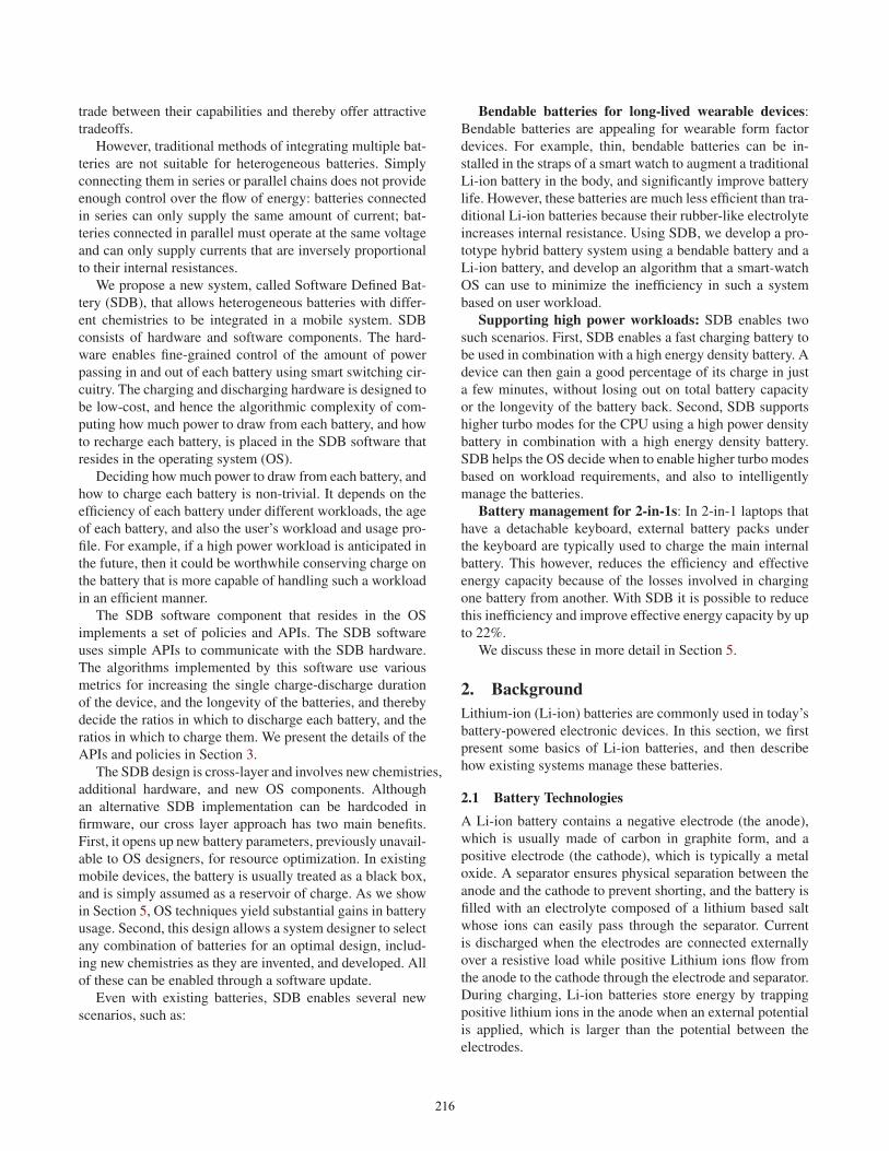
Type 1: LiFePO4 Cathode, high-density liquid polymer separatorType 2: CoO2 Cathode, high-density liquid polymer separatorType 3: CoO2 Cathode, low-density liquid polymer separatorType 4: CoO2 Cathode, rubber-like solid ceramic separator
(a) Li-ion batteries compared
75
80
85
90
95
100
105
0 100 200 300 400 500 600
Capa
city
Aft
er N
Cyc
les (
%)
Cycle Count
0.5A 0.7A 1.0A
(b) Charging rate affects longevity
0
5
10
15
20
25
30
35
0.00 0.25 0.50 0.75 1.00 1.25 1.50 1.75 2.00
Inte
rnal
Hea
t Los
s (%
)
Power Used to Drain Battery (C Rate)
Type 2 Type 3 Type 4
(c) Discharging rate vs. lost energy
Figure 1. Li-ion Battery Properties
Li-ion battery capabilities, such as longevity, energy den-
sity, and internal resistance, are largely determined by the
materials used for the electrodes and the separator. The bat-
tery’s gravimetric and volumetric energy densities are af-
fected by the strength of the separator. The resistance of the
battery, and hence its inefficiencies, depend on the resistance
of the separator, which typically increases with the age of the
battery. The power density of the battery is also affected by
aging. The structural integrity of the electrodes determines
how much energy they can store – some Lithium ions get
permanently trapped in the anode. The anodes can develop
cracks as they age, which can ultimately reduce both energy
and power densities because Lithium ions get permanently
trapped within the cracks. The material used for the elec-
trode determines the initial energy and power densities, and
also the expected longevity [5].
Figure 1(a) demonstrates the capabilities of four popular
Li-ion batteries, which differ in the chemistry of materials
used for the cathode and the separator. All four batteries have
graphite as their anode.
Batteries of Type 1 are typically used in powered tools
that need to charge quickly and provide high power for a
short duration of time while not requiring a large energy
capacity. Such batteries are a poor choice for mobile devices
because of their poor energy density – a Type 1 battery is
usually double the volume of a Type 2 battery with the same
energy capacity. Type 2 batteries are commonly used in most
mobile devices today. We measure the loss in capacity with
respect to number of charge-discharge cycles for a sample
Type 2 battery, and observe that the battery degrades much
faster when discharged at higher current values, as shown in
Figure 1(b).
Type 3 batteries are an emerging variation over Type 2
that have a slightly higher power density at the expense of
some energy density. This is achieved by making the sepa-
rator less dense allowing more Lithium ions to pass through
per unit time. However, to retain enough strength to sepa-
rate the electrodes, the weight of the separator is kept the
same and this usually leads to decreased energy density as
separators cannot store energy – only the electrodes can. Fi-
nally, Type 4 is another emerging battery that is flexible and
bendable because of the physical properties of the rubber-
like (ceramic-based) separator used – while the electrodes
are implemented by coating material along the cell’s walls.
Unfortunately, such separators increase the resistance to pas-
sage of ions and thereby result in reduced power density and
higher inefficiency, as shown in Figure 1(c).
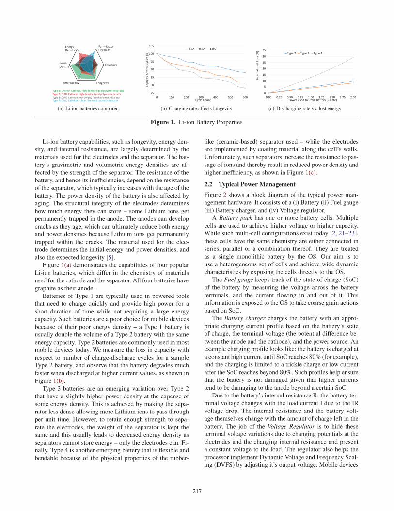
2.2 Typical Power ManagementFigure 2 shows a block diagram of the typical power man-
agement hardware. It consists of a (i) Battery (ii) Fuel gauge
(iii) Battery charger, and (iv) Voltage regulator.
A Battery pack has one or more battery cells. Multiple
cells are used to achieve higher voltage or higher capacity.
While such multi-cell configurations exist today [2, 21–23],
these cells have the same chemistry are either connected in
series, parallel or a combination thereof. They are treated
as a single monolithic battery by the OS. Our aim is to
use a heterogeneous set of cells and achieve wide dynamic
characteristics by exposing the cells directly to the OS.
The Fuel gauge keeps track of the state of charge (SoC)
of the battery by measuring the voltage across the battery
terminals, and the current flowing in and out of it. This
information is exposed to the OS to take coarse grain actions
based on SoC.
The Battery charger charges the battery with an appro-
priate charging current profile based on the battery’s state
of charge, the terminal voltage (the potential difference be-
tween the anode and the cathode), and the power source. An
example charging profile looks like: the battery is charged at
a constant high current until SoC reaches 80% (for example),
and the charging is limited to a trickle charge or low current
after the SoC reaches beyond 80%. Such profiles help ensure
that the battery is not damaged given that higher currents
tend to be damaging to the anode beyond a certain SoC.
Due to the battery’s internal resistance R, the battery ter-
minal voltage changes with the load current I due to the IR
voltage drop. The internal resistance and the battery volt-
age themselves change with the amount of charge left in the
battery. The job of the Voltage Regulator is to hide these
terminal voltage variations due to changing potentials at the
electrodes and the changing internal resistance and present
a constant voltage to the load. The regulator also helps the
processor implement Dynamic Voltage and Frequency Scal-
ing (DVFS) by adjusting it’s output voltage. Mobile devices
217
BatteryCharger
Fuel Gauge
Switched Mode Voltage
Regulator
V
I
Fixed charging profile
Switch Inductor
Capacitor
SwitchingControl
OutputInput
Battery
Figure 2. The traditional power management hardware
use switched mode voltage regulators due to their high ef-
ficiency. As the name implies, a switch mode power supply
contains a switch that opens and closes to transfer packets of
energy from the battery to an inductor. The inductor’s volt-
age is smoothed using a capacitor (figure 2). A control loop
maintains a constant voltage under varying load currents by
changing the energy per packet or the packet switching fre-
quency.
Typically, all these modules are contained in a single inte-
grated circuit called a Power Management Integrated Circuit
(PMIC) in a mobile device. The PMIC communicates with
the OS over a serial bus. In current designs, the interactions
between the OS and PMIC are limited to query operations,
such as inquiring about remaining charge in the battery, ter-
minal voltage or the cycle count. These parameters are ex-
posed through the Advanced Configuration and Power In-
terface (ACPI). However, none of these APIs allow the OS
to set the battery parameters, and in particular to change the
amount of charge to be drawn from or provided to each cell
within a battery pack. Through the SDB system, we propose
enabling fine grain control over the behavior of these hard-
ware sub modules by exposing a richer software API to the
OS to dynamically change the amount of charge to be drawn
from or provided to each battery.
3. SDB DesignSDB allows a device to use diverse batteries through fine-
grain control of the amount of charge flowing in and out of
each battery. SDB provides APIs to the OS to change the
aforementioned power values based on user workload. We
describe the SDB system in detail in this section.
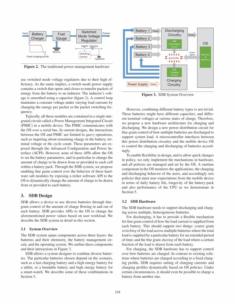
3.1 System OverviewThe SDB system spans components across three layers: the
batteries and their chemistry, the battery management cir-
cuit, and the operating system. We outline these components
and their interactions in Figure 3.
SDB allows a system designer to combine diverse batter-
ies. The particular batteries chosen depend on the scenario,
such as a fast charging battery and a high energy battery for
a tablet, or a bendable battery and high energy battery for
a smart-watch. We describe some of these combinations in
Section 5.
Battery 1
OS
Power
Power
ControlSignal
Battery 2
Battery 3
Battery 4
Discharging Circuitry
SDBDischarging
Circuit
SDB Policy &
Algorithms
Charging Circuitry
SDBCharging
Circuit
Power Supply Power
μController
Figure 3. SDB System Overview
However, combining different battery types is not trivial.
These batteries might have different capacities, and differ-
ent terminal voltages at various states of charge. Therefore,
we propose a new hardware architecture for charging and
discharging. We design a new power distribution circuit for
fine-grain control of how multiple batteries are discharged to
support system load. A microcontroller interfaces between
this power distribution circuitry and the mobile device OS
to control the charging and discharging of batteries accord-
ingly.
To enable flexibility in design, and to allow quick changes
in policy, we only implement the mechanisms in hardware,
and all policies are managed and set by the OS. A runtime
component in the OS monitors the applications, the charging
and discharging behavior of the users, and accordingly sets
policies that meet user expectations from the mobile device
in terms of daily battery life, longevity of the battery-pack
and also performance of the CPU as we demonstrate in
Section 5.
3.2 SDB HardwareThe SDB hardware needs to support discharging and charg-
ing across multiple, heterogeneous batteries.
For discharging, it has to provide a flexible mechanism
for fine grain control of how the load current is supplied from
each battery. This should support two things: coarse grain
switching of the load across multiple batteries where the total
load is supplied by a particular battery for an extended period
of time; and the fine grain sharing of the load where a certain
fraction of the load is drawn from each battery.
For charging, the SDB hardware has to support control
over how batteries are charged. In contrast to existing solu-
tions where batteries are charged according to a fixed charg-
ing profile, SDB requires setting of charging currents and
charging profiles dynamically based on OS policies. Under
certain circumstances, it should even be possible to charge a
battery from another one.
218
Designing these flexible charging and discharging cir-
cuits are challenging for two reasons. First, due to the high
currents that flow in these circuits, any electronic compo-
nent in series with the current flow will cause energy losses.
Hence, these circuit designs should introduce as few of these
components as possible. Second, each extra component we
introduce can increase the weight, volume and bill of ma-
terial (BoM) cost of the device, which will make the pro-
posed solution unattractive in the highly competitive hard-
ware market.
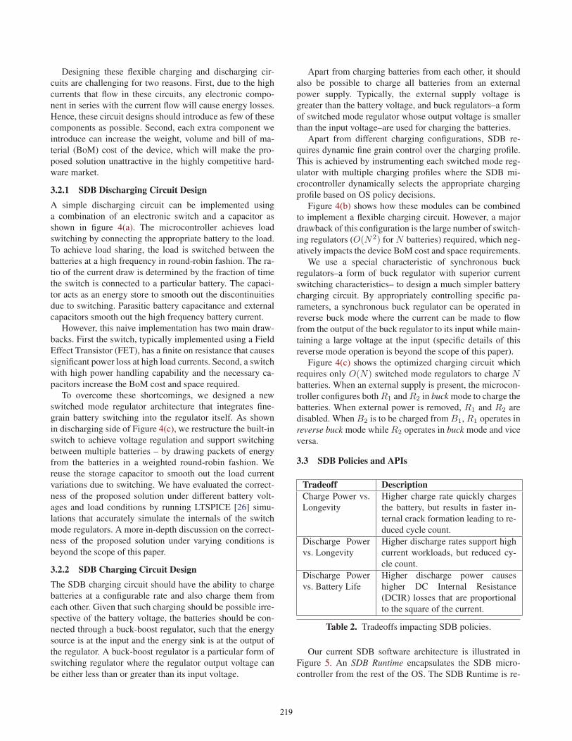
3.2.1 SDB Discharging Circuit DesignA simple discharging circuit can be implemented using
a combination of an electronic switch and a capacitor as
shown in figure 4(a). The microcontroller achieves load
switching by connecting the appropriate battery to the load.
To achieve load sharing, the load is switched between the
batteries at a high frequency in round-robin fashion. The ra-
tio of the current draw is determined by the fraction of time
the switch is connected to a particular battery. The capaci-
tor acts as an energy store to smooth out the discontinuities
due to switching. Parasitic battery capacitance and external
capacitors smooth out the high frequency battery current.
However, this naive implementation has two main draw-
backs. First the switch, typically implemented using a Field
Effect Transistor (FET), has a finite on resistance that causes
significant power loss at high load currents. Second, a switch
with high power handling capability and the necessary ca-
pacitors increase the BoM cost and space required.
To overcome these shortcomings, we designed a new
switched mode regulator architecture that integrates fine-
grain battery switching into the regulator itself. As shown
in discharging side of Figure 4(c), we restructure the built-in
switch to achieve voltage regulation and support switching
between multiple batteries – by drawing packets of energy
from the batteries in a weighted round-robin fashion. We
reuse the storage capacitor to smooth out the load current
variations due to switching. We have evaluated the correct-
ness of the proposed solution under different battery volt-
ages and load conditions by running LTSPICE [26] simu-
lations that accurately simulate the internals of the switch
mode regulators. A more in-depth discussion on the correct-
ness of the proposed solution under varying conditions is
beyond the scope of this paper.
3.2.2 SDB Charging Circuit DesignThe SDB charging circuit should have the ability to charge
batteries at a configurable rate and also charge them from
each other. Given that such charging should be possible irre-
spective of the battery voltage, the batteries should be con-
nected through a buck-boost regulator, such that the energy
source is at the input and the energy sink is at the output of
the regulator. A buck-boost regulator is a particular form of
switching regulator where the regulator output voltage can
be either less than or greater than its input voltage.
Apart from charging batteries from each other, it should
also be possible to charge all batteries from an external
power supply. Typically, the external supply voltage is
greater than the battery voltage, and buck regulators–a form
of switched mode regulator whose output voltage is smaller
than the input voltage–are used for charging the batteries.
Apart from different charging configurations, SDB re-
quires dynamic fine grain control over the charging profile.
This is achieved by instrumenting each switched mode reg-
ulator with multiple charging profiles where the SDB mi-
crocontroller dynamically selects the appropriate charging
profile based on OS policy decisions.
Figure 4(b) shows how these modules can be combined
to implement a flexible charging circuit. However, a major
drawback of this configuration is the large number of switch-
ing regulators (O(N2) for N batteries) required, which neg-
atively impacts the device BoM cost and space requirements.
We use a special characteristic of synchronous buck
regulators–a form of buck regulator with superior current
switching characteristics– to design a much simpler battery
charging circuit. By appropriately controlling specific pa-
rameters, a synchronous buck regulator can be operated in
reverse buck mode where the current can be made to flow
from the output of the buck regulator to its input while main-
taining a large voltage at the input (specific details of this
reverse mode operation is beyond the scope of this paper).
Figure 4(c) shows the optimized charging circuit which
requires only O(N) switched mode regulators to charge Nbatteries. When an external supply is present, the microcon-
troller configures both R1 and R2 in buck mode to charge the
batteries. When external power is removed, R1 and R2 are
disabled. When B2 is to be charged from B1, R1 operates in
reverse buck mode while R2 operates in buck mode and vice
versa.
3.3 SDB Policies and APIs
Tradeoff DescriptionCharge Power vs.
Longevity
Higher charge rate quickly charges
the battery, but results in faster in-
ternal crack formation leading to re-
duced cycle count.
Discharge Power
vs. Longevity
Higher discharge rates support high
current workloads, but reduced cy-
cle count.
Discharge Power
vs. Battery Life
Higher discharge power causes
higher DC Internal Resistance
(DCIR) losses that are proportional
to the square of the current.
Table 2. Tradeoffs impacting SDB policies.
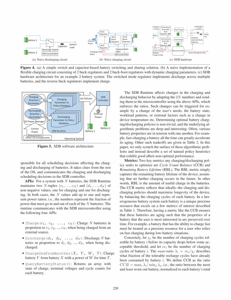
Our current SDB software architecture is illustrated in
Figure 5. An SDB Runtime encapsulates the SDB micro-
controller from the rest of the OS. The SDB Runtime is re-
219
Microcontroler
Battery 1
SystemLoad
Battery 2Electronic Switch
Capacitor
(a) Naive discharging circuit
Buck Regulator
Microcontroller
External Power
Charging ProfileSelect
Buck-Boost Regulator
Buck Regulator
Buck-Boost Regulator
Charging ProfileSelect
(b) Naive charging circuit
Fuel Gauge
Modified Switched Mode Regulator
Synchronous Reversible
Buck Regulator (R1)
Fuel Gauge
Microcontroller
Power OutPower
In
MultipleCharge Profiles
Power Management Bus
Synchronous Reversible
Buck Regulator (R2)
B1
B2
ChargingCircuit
DischargingCircuit
(c) SDB hardware
Figure 4. (a) A simple switch and capacitor-based battery switching and sharing solution. (b) A naive implementation of a
flexible charging circuit consisting of 2 buck regulators and 2 buck-boot regulators with dynamic charging parameters. (c) SDB
hardware architecture for an example 2-battery system. The switched mode regulator implements discharge across multiple
batteries, and the reverse buck regulators implement charge.
Operating System
SDB Controller
Battery 2Battery 1
OS Power Manager
SDB Runtime
Charging Directive
Parameter
Discharging Directive
Parameter
Other OS Components
External PowerDischarging
Parameter to Policy Database
Charging Parameter to
Policy Database
MapSet Policies
Convey Power
Requirement
Figure 5. SDB software architecture
sponsible for all scheduling decisions affecting the charg-
ing and discharging of batteries. It takes clues from the rest
of the OS, and communicates the charging and discharging
scheduling decisions to the SDB controller.
APIs: For a system with N batteries, the SDB Runtime
maintains two N -tuples (c1, . . . , cN ) and (d1, . . . , dN ) of
non-negative values, one for charging and one for discharg-
ing. In both cases, the N values add up to one and repre-
sent power ratios; i.e., the numbers represent the fraction of
power that must go in and out of each of the N batteries. The
runtime communicates with the SDB microcontroller using
the following four APIs:
• Charge(c1, c2, ..., cN): Charge N batteries in
proportion to c1, c2, ..., cN , when being charged from an
external source.
• Discharge(d1, d2, ..., dN): Discharge N bat-
teries in proportion to d1, d2, ..., dN , when being dis-
charged.
• ChargeOneFromAnother(X, Y , W, T): Charge
battery Y from battery X with a power of W for time T .
• QueryBatteryStatus(): Returns an array with
state of charge, terminal voltages and cycle counts for
each battery.
The SDB Runtime affects changes in the charging and
discharging behavior by adapting the 2N numbers and send-
ing them to the microcontroller using the above APIs, which
enforces the ratios. Such changes can be triggered for ex-
ample by a change of the user’s needs, the battery state,
workload patterns, or external factors such as a change in
device temperature etc. Determining optimal battery charg-
ing/discharging policies is non-trivial, and the underlying al-
gorithmic problems are deep and interesting. Often, various
battery properties are in tension with one another. For exam-
ple, fast-charging a battery all the time can greatly accelerate
its aging. Other such tradeoffs are given in Table 2. In this
paper, we only scratch the surface of these algorithmic prob-
lems and instead describe a set of natural policy heuristics
that exhibit good albeit non-optimal performance.
Metrics: Two key metrics any charging/discharging pol-
icy seeks to optimize are Cycle Count Balance (CCB) and
Remaining Battery Lifetime (RBL). The RBL metric simply
captures the remaining battery lifetime of the device, assum-
ing that no further charging occurs in the future. In other
words, RBL is the amount of useful charge in the batteries.
The CCB metric reflects that–ideally–the charging and dis-
charging policies should maximize longevity of the device,
by balancing the charging cycles of each battery. In a het-
erogeneous battery system each battery is a unique precious
resource that excels on a few metrics of interest described
in Table 1. Therefore, having a metric like the CCB ensures
that these batteries are aging such that the properties of a
battery that the user is most interested in are preserved over
time. For example, a battery that has the ability to charge fast
must be treated as a precious resource for a user who relies
on fast charging during low-battery situations.
Concretely, let χi be the number of charging cycles tol-
erable by battery i before its capacity drops below some ac-
ceptable threshold, and let cci be the number of charging
cycles of battery i. The wear-ratio λi = cci/χi describes
what fraction of the tolerable recharge cycles have already
been consumed by battery i. We define CCB as the ratio
CCB = maxi λi/minj λj , i.e., the ratio between the most
and least worn-out battery, normalized to each battery’s total
220
tolerable cycle count. A device’s longevity is maximized by
balancing CCB.
Charge/Discharge Algorithms: The heuristics currently
driving our SDB Runtime are simple and driven by the
following observation: It is possible to derive charging
and discharging algorithms that (in isolation!) optimize the
CCB and the instantaneous RBL metric. We use these four
“optimal” algorithms (CCB-Charge, RBL-Charge, CCB-
Discharge, and RBL-Discharge) and weigh them by means
of two parameters–Charging and Discharging Directive
Parameter–handed to the SDB Runtime by the rest of the
OS. Essentially, these parameters guide the SDB Runtime
to weigh one of the algorithms more heavily at any moment
in time. For example, a low value of the Charging Directive
Parameter indicates that the user is in no hurry (e.g. charg-
ing at night), and that the Runtime should prioritize the use
of the CCB-Charge algorithm. On the other hand, a high
value of this parameter would lead the Runtime to prioritize
the RBL-Charge algorithm in order to increase the useful
charge (and thus the remaining battery lifetime) in the bat-
teries as quickly as possible - say just before boarding an
airplane. The discharge scenario is similar.
The CCB-Charge and CCB-Discharge algorithms are
simple. These policies essentially enforce the controller to
schedule the batteries (either for charging and discharging)
in such a way that the resulting CCB is minimized i.e. is as
close to 1 as possible. Our RBL-algorithms are more inter-
esting. Consider the discharge case, and let y1, . . . , yN be the
amount of current drawn from each of the batteries. The key
underlying insight is that we can maximize the instantaneous
RBL of the battery system by minimizing the total resistance
losses across all the batteries. This can be achieved if the re-sistances of the batteries are proportional to the square-rootof their DCIR-to-SoC ratios. Thus, the RBL-Discharge al-
gorithm seeks to allocate the currents y1, . . . , yN in such a
way that the effective resistances of batteries are as much
as possible proportional to the square-root of their DCIR-
to-SoC rates minimizing the total energy wasted through
resistive losses. Mathematically speaking, let δi be the in-
stantaneous derivative of battery i’s DCIR curve, and let Ri
be the current resistance. Then, the RBL-Discharge algo-
rithm balances R′i =
√δi/λ, where R′
i = Ri + δiyi and
λ is a Lagrangian multiplier constant. Again, the case for
charging (RBL-Charge) is similar. The SDB runtime calcu-
lates these power values at coarse granular time steps and
updates the ratios based on the DCIR-SoC curves given by
the manufacturer of the batteries.
A word of caution is necessary. The above RBL-algorithms
are “optimal” only in an instantaneous sense. They minimize
the instantaneous decrease of RBL (when discharging), or
maximize the instantaneous increase of RBL (when charg-
ing). However, they are not globally optimal. Across the
length of an entire workload, these algorithms might not ac-
tually maximize battery lifetime as we show in Section 5;
��������������
�������
� ����� ���
�� ��������� ���
��������������������
����������������
���������
������ ��
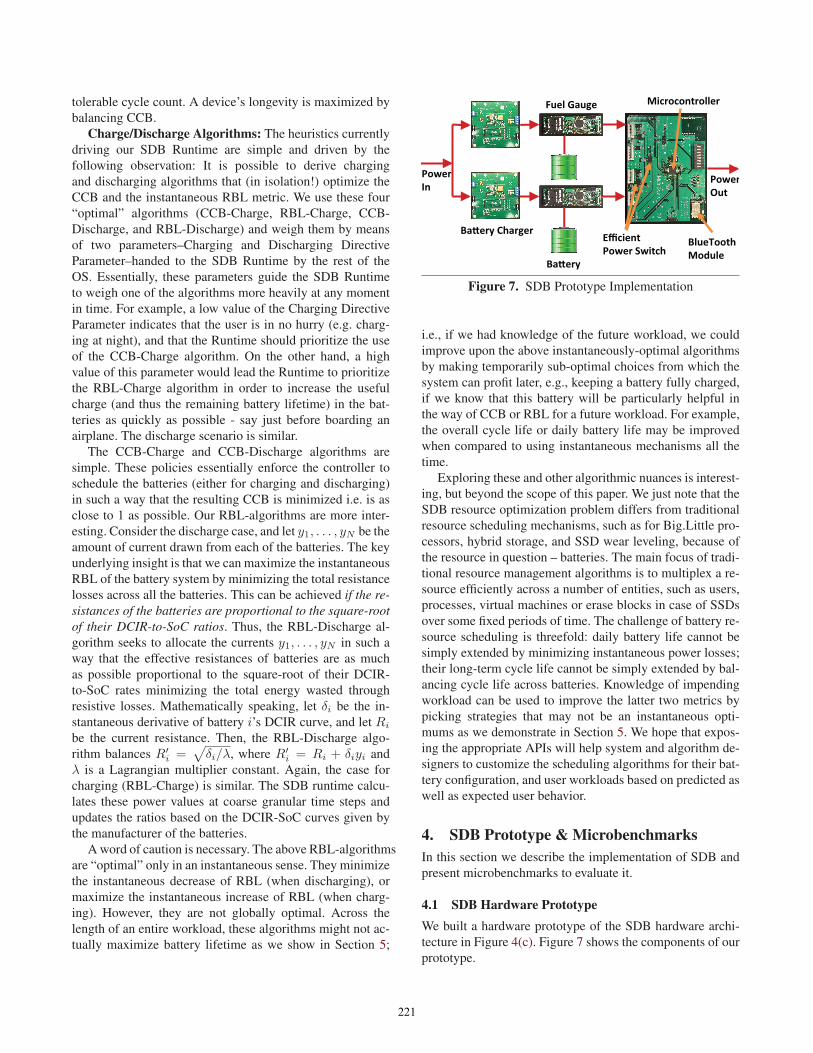
Figure 7. SDB Prototype Implementation
i.e., if we had knowledge of the future workload, we could
improve upon the above instantaneously-optimal algorithms
by making temporarily sub-optimal choices from which the
system can profit later, e.g., keeping a battery fully charged,
if we know that this battery will be particularly helpful in
the way of CCB or RBL for a future workload. For example,
the overall cycle life or daily battery life may be improved
when compared to using instantaneous mechanisms all the
time.
Exploring these and other algorithmic nuances is interest-
ing, but beyond the scope of this paper. We just note that the
SDB resource optimization problem differs from traditional
resource scheduling mechanisms, such as for Big.Little pro-
cessors, hybrid storage, and SSD wear leveling, because of
the resource in question – batteries. The main focus of tradi-
tional resource management algorithms is to multiplex a re-
source efficiently across a number of entities, such as users,
processes, virtual machines or erase blocks in case of SSDs
over some fixed periods of time. The challenge of battery re-
source scheduling is threefold: daily battery life cannot be
simply extended by minimizing instantaneous power losses;
their long-term cycle life cannot be simply extended by bal-
ancing cycle life across batteries. Knowledge of impending
workload can be used to improve the latter two metrics by
picking strategies that may not be an instantaneous opti-
mums as we demonstrate in Section 5. We hope that expos-
ing the appropriate APIs will help system and algorithm de-
signers to customize the scheduling algorithms for their bat-
tery configuration, and user workloads based on predicted as
well as expected user behavior.
4. SDB Prototype & MicrobenchmarksIn this section we describe the implementation of SDB and
present microbenchmarks to evaluate it.
4.1 SDB Hardware PrototypeWe built a hardware prototype of the SDB hardware archi-
tecture in Figure 4(c). Figure 7 shows the components of our
prototype.
221
��
����
��
����
��
���� ���� ���� �� �� �� ���������������
����� ����
��
������� �����������
(a) The % power loss of the discharge
circuit vs discharge power
�������������������������� �
��� ��� ���� ���� ���� ���� ���� ����
�������
���������
��
����������������
(b) The % error of the measured %
discharge current vs the % discharge
current set by the microcontroller.
���
���
���
���
���
����
���� �� ���� ���� ���� ���� �� ����������
�������
� ����������
���
��
�������������������
(c) Efficiency of the charging circuit
as a % of the typical efficiency of the
charging chip vs charging current.
��
����
����
���
���
����
����
���� ��� ���� ���� �� ���� ��� ���� ���� ��
�������
����������
��
���������������
(d) The % error of the measured
charging current vs the charging cur-
rent set by the microcontroller
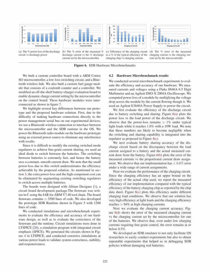
Figure 6. SDB Hardware Microbenchmarks
We built a custom controller board with a ARM Cortex
M3 microcontroller, a low-loss switching circuit, and a Blue-
tooth wireless link. We also built a custom fuel gauge mod-
ule that consists of a coulomb counter and a controller. We
modified an off-the-shelf battery-charger evaluation board to
enable dynamic charge current setting by the microcontroller
on the control board. These hardware modules were inter-
connected as shown in figure 7.
We highlight several key differences between our proto-
type and the proposed hardware solution. First, due to the
difficulty of making hardware connections directly to the
power management serial bus on our experimental devices,
we use a Bluetooth wireless connection to interface between
the microcontroller and the SDB runtime in the OS. We
power the Bluetooth radio module on the hardware prototype
using an external power source to eliminate any interference
with results.
Since it is difficult to modify the existing switched mode
regulators to achieve fine-grain current sharing, we used an
ideal diode to switch between the batteries. The switching
between batteries is extremely fast, and hence the battery
sees a constant, smooth current draw. We note that the small
power-loss due to this switch underestimates the efficiency
achievable by the proposed solution. As mentioned in sec-
tion 3, the extra power-loss and the high component cost can
be eliminated by augmenting existing switching regulators
to switch across multiple batteries.
The boards were designed with Altium Designer [1], a
circuit board development package.The firmware was writ-
ten in C using the IAR for ARM V7.40 tool chain. The board
firmware contains � 3500 lines of code. We also developed
the prototype SDB Runtime shown in Figure 5 with 1200
lines of code.
We conducted simulations and microbenchmark experi-
ments to evaluate the efficiency and accuracy of our hard-
ware design, as well as to evaluate the correctness of the
firmware and the runtime. Circuit simulations were done in
LTSPICE [26], a simulation program with integrated circuit
emphasis (SPICE). We generated the circuits shown in Fig-
ure 4 in LTSPICE, and conducted extensive simulations at
various power loads to validate system correctness, stability,
and responsiveness.
4.2 Hardware Microbenchmark resultsWe conducted several microbenchmark experiments to eval-
uate the efficiency and accuracy of our hardware. We mea-
sured currents and voltages using a Fluke 8846A 6.5 Digit
Multimeter and an Agilent DSO-X 2004A Oscilloscope. We
computed power loss of a module by multiplying the voltage
drop across the module by the current flowing though it. We
used an Agilent E3640A Power Supply to power the circuit.
We first evaluate the efficiency of the discharge circuit
due to battery switching and sharing. Figure 6(a) plots the
power loss vs the load power of the discharge circuit. We
observe that the power-loss remains � 1% under typical
light loads while it reaches 1.6% with a 10W load. We note
that these numbers are likely to become negligible when
the switching and sharing capability is integrated into the
regulator as proposed in Figure 4(c).
We next evaluate battery sharing accuracy of the dis-
charge circuit based on the discrepancy between the load
current assigned to a battery and the actual measured cur-
rent draw from the battery. Figure 6(b) plots the error of the
measured currents vs the proportional current draw assign-
ment. We observe that our implementation has < 0.6% error
under a wide range of current assignments.
Next we evaluate the performance of the charging circuit.
Since the charging efficiency has an upper bound on the
efficiency of the actual chip used, we report the measured
efficiency of our implementation compared with the typical
efficiency of the battery charging chip as reported by the chip
data sheet. Figure 6(c) plots this efficiency under different
charging load conditions. We observe that our solution has
very high efficiency at light loads and the charging efficiency
reaches � 94% at high charging currents.
Next we evaluate the charging current accuracy. Fig-
ure 6(d) shows the error of the measured charging current
vs the charging current set by the microcontroller for one
of the batteries. We observe that, even under low charging
currents requiring fine-grain control, the error remains at or
below 0.5%.
We developed an SDB emulator to not only facilitate OS
researchers to easily conduct experiments but also to obtain
repeatable experiments that helped us in debugging SDB
policies without damaging real batteries.
222
Open Circuit Potential
Internal Resistance
Concentration Resistance
Plate Capacitance
Current
AA B
(a) Battery Model
2.72.93.13.33.53.73.94.14.3
0 10 20 30 40 50 60 70 80 90 100
Ope
n Ci
rcui
t Pot
entia
l (Vo
lts)
State of Charge (%)
Battery 1 Battery 2 Battery 3 Battery 4 Battery 5
(b) Open Circuit Potential
0.01
0.10
1.00
10.00
0 10 20 30 40 50 60 70 80 90 100
Resis
tanc
e (O
hms)
State of Charge (%)
Battery 1 Battery 2 Battery 3 Battery 4Battery 5 Battery 6 Battery 7 Battery 8
(c) Internal Resistance
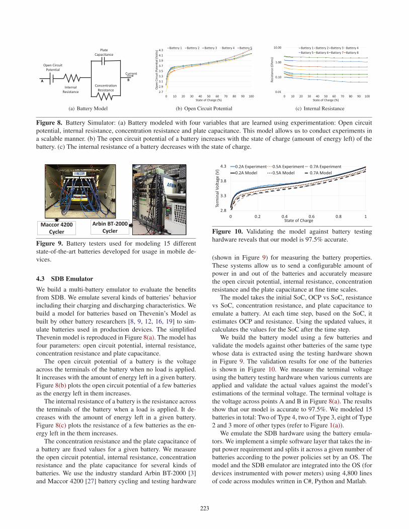
Figure 8. Battery Simulator: (a) Battery modeled with four variables that are learned using experimentation: Open circuit
potential, internal resistance, concentration resistance and plate capacitance. This model allows us to conduct experiments in
a scalable manner. (b) The open circuit potential of a battery increases with the state of charge (amount of energy left) of the
battery. (c) The internal resistance of a battery decreases with the state of charge.
Maccor 4200 Cycler
Arbin BT-2000 Cycler
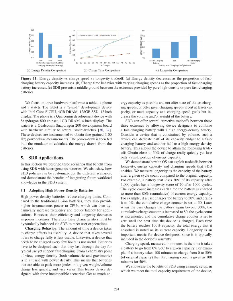
Figure 9. Battery testers used for modeling 15 different
state-of-the-art batteries developed for usage in mobile de-
vices.
4.3 SDB EmulatorWe build a multi-battery emulator to evaluate the benefits
from SDB. We emulate several kinds of batteries’ behavior
including their charging and discharging characteristics. We
build a model for batteries based on Thevenin’s Model as
built by other battery researchers [8, 9, 12, 16, 19] to sim-
ulate batteries used in production devices. The simplified
Thevenin model is reproduced in Figure 8(a). The model has
four parameters: open circuit potential, internal resistance,
concentration resistance and plate capacitance.
The open circuit potential of a battery is the voltage
across the terminals of the battery when no load is applied.
It increases with the amount of energy left in a given battery.
Figure 8(b) plots the open circuit potential of a few batteries
as the energy left in them increases.
The internal resistance of a battery is the resistance across
the terminals of the battery when a load is applied. It de-
creases with the amount of energy left in a given battery.
Figure 8(c) plots the resistance of a few batteries as the en-
ergy left in the them increases.
The concentration resistance and the plate capacitance of
a battery are fixed values for a given battery. We measure
the open circuit potential, internal resistance, concentration
resistance and the plate capacitance for several kinds of
batteries. We use the industry standard Arbin BT-2000 [3]
and Maccor 4200 [27] battery cycling and testing hardware
2.8
3.3
3.8
4.3
0 0.2 0.4 0.6 0.8 1Te
rmin
al V
olta
ge (V
)State of Charge
0.2A Experiment 0.5A Experiment 0.7A Experiment0.2A Model 0.5A Model 0.7A Model
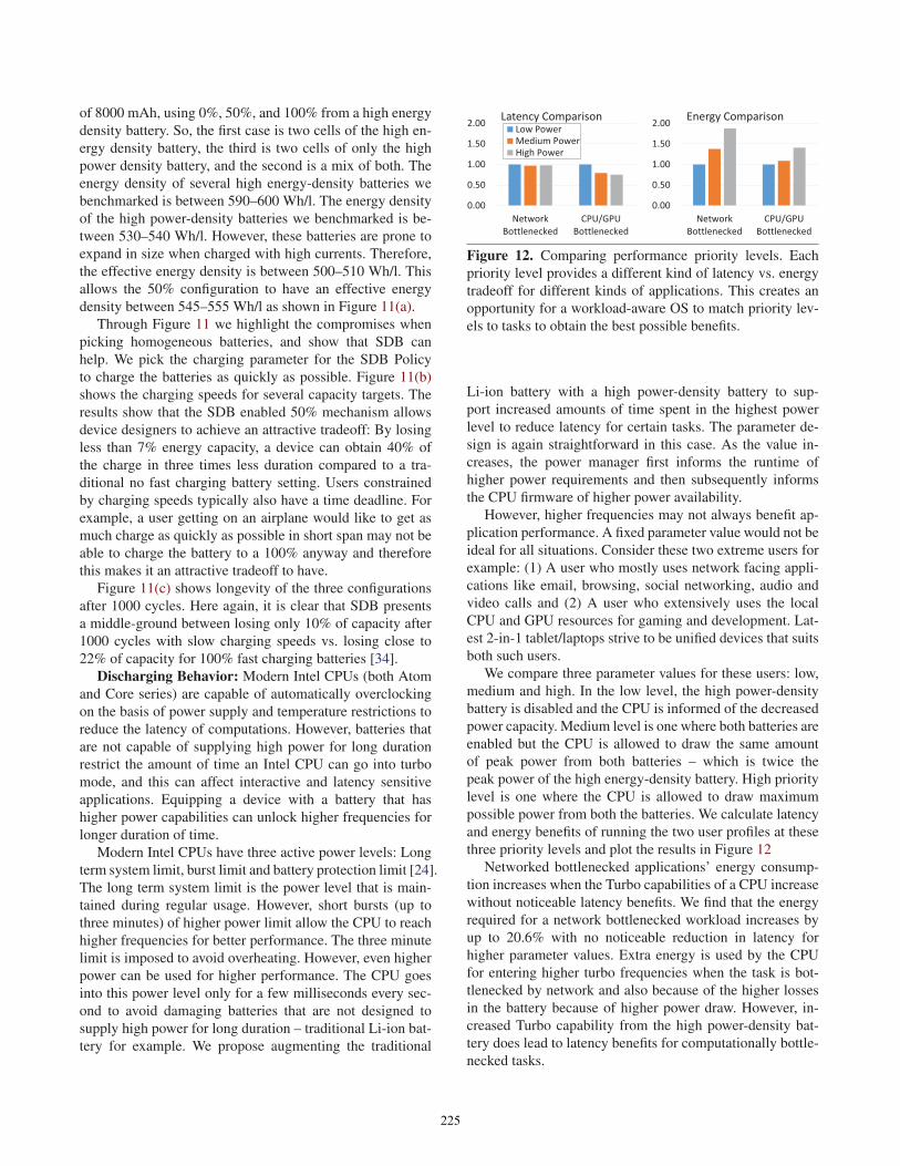
Figure 10. Validating the model against battery testing
hardware reveals that our model is 97.5% accurate.
(shown in Figure 9) for measuring the battery properties.
These systems allow us to send a configurable amount of
power in and out of the batteries and accurately measure
the open circuit potential, internal resistance, concentration
resistance and the plate capacitance at fine time scales.
The model takes the initial SoC, OCP vs SoC, resistance
vs SoC, concentration resistance, and plate capacitance to
emulate a battery. At each time step, based on the SoC, it
estimates OCP and resistance. Using the updated values, it
calculates the values for the SoC after the time step.
We build the battery model using a few batteries and
validate the models against other batteries of the same type
whose data is extracted using the testing hardware shown
in Figure 9. The validation results for one of the batteries
is shown in Figure 10. We measure the terminal voltage
using the battery testing hardware when various currents are
applied and validate the actual values against the model’s
estimations of the terminal voltage. The terminal voltage is
the voltage across points A and B in Figure 8(a). The results
show that our model is accurate to 97.5%. We modeled 15
batteries in total: Two of Type 4, two of Type 3, eight of Type
2 and 3 more of other types (refer to Figure 1(a)).
We emulate the SDB hardware using the battery emula-
tors. We implement a simple software layer that takes the in-
put power requirement and splits it across a given number of
batteries according to the power policies set by an OS. The
model and the SDB emulator are integrated into the OS (for
devices instrumented with power meters) using 4,800 lines
of code across modules written in C#, Python and Matlab.
223
500
520
540
560
580
600
0% 50% 100%
Ener
gy D
ensit
y (W
h/L)
Battery Configuration (% of fast-charging battery by capacity)
(a) Energy Density Comparison
0
20
40
60
80
100
120
15 20 25 30 35 40 45 50 55 60 65 70 75 80 85
Char
ging
Tim
e (m
in)
% Charged
Traditional Battery SDB Fast Charging Battery
(b) Charge Time Comparison
70
75
80
85
90
95
All Fast ChargingBattery
SDB No Fast ChargingBattery
Long
evity
(100
0 Cy
cles
)
Battery and Charging Configuration
(c) Longevity Comparison
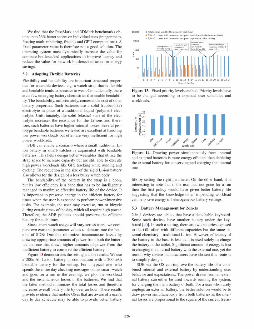
Figure 11. Energy density vs charge speed vs longevity tradeoff: (a) Energy density decreases as the proportion of fast-
charging battery capacity increases. (b) Charge time behavior with varying charging speeds as the proportion of fast-charging
battery increases. (c) SDB presents a middle ground between the extremes provided by pure high-density or pure fast-charging
batteries.
We focus on three hardware platforms: a tablet, a phone
and a watch. The tablet is a “2-in-1” development device
with Intel Core i5 CPU, 4GB DRAM, 128GB SSD, 12 inch
display. The phone is a Qualcomm development device with
Snapdragon 800 chipset, 1GB DRAM, 4 inch display. The
watch is a Qualcomm Snapdragon 200 development board
with hardware similar to several smart-watches [36, 37].
These devices are instrumented to obtain fine grained (100
Hz) power-draw measurements. The power-draw is then fed
into the emulator to calculate the energy drawn from the
batteries.
5. SDB ApplicationsIn this section we describe three scenarios that benefit from
using SDB with heterogeneous batteries. We also show how
SDB policies can be customized for the different scenarios,
and demonstrate the benefits of integrating future workload
knowledge in the SDB system.
5.1 Adopting High Power-Density BatteriesHigh power-density batteries reduce charging times. Com-
pared to the traditional Li-ion batteries, they also provide
higher instantaneous power to CPUs, which can then dy-
namically increase frequency and reduce latency for appli-
cations. However, their efficiency and longevity decreases
as power increases. Therefore these characteristics must be
dynamically balanced via SDB to meet user expectations.
Charging Behavior: The amount of time a device takes
to charge affects its usability. A device that takes several
hours to charge fully is less usable. Likewise, a device that
needs to be charged every few hours is not useful. Batteries
have to be designed such that they last through the day for
typical use yet support fast charging. From a chemistry point
of view, energy density (both volumetric and gravimetric)
is in a tussle with power density. This means that batteries
that are able to pack more joules in a given weight/volume
charge less quickly, and vice versa. This leaves device de-
signers with three incompatible scenarios: Get as much en-
ergy capacity as possible and not offer state-of-the-art charg-
ing speeds, or offer great charging speeds albeit at lesser ca-
pacity, or meet capacity and charging speed goals but in-
crease the volume and/or weight of the battery.
SDB can offer several attractive tradeoffs between these
three extremes by allowing device designers to combine
a fast-charging battery with a high energy-density battery.
Consider a device that is constrained by volume, such a
device can dedicate half of its capacity budget to a fast-
charging battery and another half to a high energy-density
battery. This allows the device to attain the following trade-
off: Obtain close to 50% of charge really quickly yet lose
only a small portion of energy capacity.
We demonstrate how an OS can exploit tradeoffs between
longevity, energy capacity and charging speeds that SDB
enables. We measure longevity as the capacity of the battery
after a given cycle count compared to the original capacity.
For example, a battery that loses 30% of its capacity after
1,000 cycles has a longevity score of 70 after 1000 cycles.
The cycle count increases each time the battery is charged
to more than 80% (cumulative) of current energy capacity.
For example, if a user charges the battery to 50% and drains
it to 0%, the cumulative charge counter is set to 50. Later
when the user charges the battery again beyond 30%, the
cumulative charge counter is increased to 80, the cycle count
is incremented and the cumulative charge counter is set to
zero until the next time the device is charged. Each time
the battery reaches 100% capacity, the total energy that it
absorbed is noted as its current capacity. Longevity is an
important metric for device designers, since it is typically
included in the device’s warranty.
Charging speed, measured in minutes, is the time it takes
a battery to go from 0% SoC to a given capacity. For exam-
ple, if a battery takes 100 minutes to charge from 0 to 50%
(of original capacity) then its charging speed is given as 100
minutes for 50%.
We showcase the benefits of SDB using a simple setup, in
which we meet the total capacity requirement of the device,
224
of 8000 mAh, using 0%, 50%, and 100% from a high energy
density battery. So, the first case is two cells of the high en-
ergy density battery, the third is two cells of only the high
power density battery, and the second is a mix of both. The
energy density of several high energy-density batteries we
benchmarked is between 590–600 Wh/l. The energy density
of the high power-density batteries we benchmarked is be-
tween 530–540 Wh/l. However, these batteries are prone to
expand in size when charged with high currents. Therefore,
the effective energy density is between 500–510 Wh/l. This
allows the 50% configuration to have an effective energy
density between 545–555 Wh/l as shown in Figure 11(a).
Through Figure 11 we highlight the compromises when
picking homogeneous batteries, and show that SDB can
help. We pick the charging parameter for the SDB Policy
to charge the batteries as quickly as possible. Figure 11(b)
shows the charging speeds for several capacity targets. The
results show that the SDB enabled 50% mechanism allows
device designers to achieve an attractive tradeoff: By losing
less than 7% energy capacity, a device can obtain 40% of
the charge in three times less duration compared to a tra-
ditional no fast charging battery setting. Users constrained
by charging speeds typically also have a time deadline. For
example, a user getting on an airplane would like to get as
much charge as quickly as possible in short span may not be
able to charge the battery to a 100% anyway and therefore
this makes it an attractive tradeoff to have.
Figure 11(c) shows longevity of the three configurations
after 1000 cycles. Here again, it is clear that SDB presents
a middle-ground between losing only 10% of capacity after
1000 cycles with slow charging speeds vs. losing close to
22% of capacity for 100% fast charging batteries [34].
Discharging Behavior: Modern Intel CPUs (both Atom
and Core series) are capable of automatically overclocking
on the basis of power supply and temperature restrictions to
reduce the latency of computations. However, batteries that
are not capable of supplying high power for long duration
restrict the amount of time an Intel CPU can go into turbo
mode, and this can affect interactive and latency sensitive
applications. Equipping a device with a battery that has
higher power capabilities can unlock higher frequencies for
longer duration of time.
Modern Intel CPUs have three active power levels: Long
term system limit, burst limit and battery protection limit [24].
The long term system limit is the power level that is main-
tained during regular usage. However, short bursts (up to
three minutes) of higher power limit allow the CPU to reach
higher frequencies for better performance. The three minute
limit is imposed to avoid overheating. However, even higher
power can be used for higher performance. The CPU goes
into this power level only for a few milliseconds every sec-
ond to avoid damaging batteries that are not designed to
supply high power for long duration – traditional Li-ion bat-
tery for example. We propose augmenting the traditional
0.00
0.50
1.00
1.50
2.00
NetworkBottlenecked
CPU/GPUBottlenecked
Latency ComparisonLow PowerMedium PowerHigh Power
0.00
0.50
1.00
1.50
2.00
NetworkBottlenecked
CPU/GPUBottlenecked
Energy Comparison
Figure 12. Comparing performance priority levels. Each
priority level provides a different kind of latency vs. energy
tradeoff for different kinds of applications. This creates an
opportunity for a workload-aware OS to match priority lev-
els to tasks to obtain the best possible benefits.
Li-ion battery with a high power-density battery to sup-
port increased amounts of time spent in the highest power
level to reduce latency for certain tasks. The parameter de-
sign is again straightforward in this case. As the value in-
creases, the power manager first informs the runtime of
higher power requirements and then subsequently informs
the CPU firmware of higher power availability.
However, higher frequencies may not always benefit ap-
plication performance. A fixed parameter value would not be
ideal for all situations. Consider these two extreme users for
example: (1) A user who mostly uses network facing appli-
cations like email, browsing, social networking, audio and
video calls and (2) A user who extensively uses the local
CPU and GPU resources for gaming and development. Lat-
est 2-in-1 tablet/laptops strive to be unified devices that suits
both such users.
We compare three parameter values for these users: low,
medium and high. In the low level, the high power-density
battery is disabled and the CPU is informed of the decreased
power capacity. Medium level is one where both batteries are
enabled but the CPU is allowed to draw the same amount
of peak power from both batteries – which is twice the
peak power of the high energy-density battery. High priority
level is one where the CPU is allowed to draw maximum
possible power from both the batteries. We calculate latency
and energy benefits of running the two user profiles at these
three priority levels and plot the results in Figure 12
Networked bottlenecked applications’ energy consump-
tion increases when the Turbo capabilities of a CPU increase
without noticeable latency benefits. We find that the energy
required for a network bottlenecked workload increases by
up to 20.6% with no noticeable reduction in latency for
higher parameter values. Extra energy is used by the CPU
for entering higher turbo frequencies when the task is bot-
tlenecked by network and also because of the higher losses
in the battery because of higher power draw. However, in-
creased Turbo capability from the high power-density bat-
tery does lead to latency benefits for computationally bottle-
necked tasks.
225
We find that the PassMark and 3DMark benchmarks ob-
tain up to 26% better scores on individual tests (integer math,
floating math, rendering, fractals and GPU computations). A
fixed parameter value is therefore not a good solution. The
operating system must dynamically increase the value for
compute bottlenecked applications to improve latency and
reduce the value for network bottlenecked tasks for energy
savings.
5.2 Adopting Flexible BatteriesFlexibility and bendability are important structural proper-
ties for wearable devices, e.g. a watch-strap that is flexible
and bendable tends to be easier to wear. Coincidentally, there
are a few emerging battery chemistries that enable bendabil-
ity. The bendability, unfortunately, comes at the cost of other
battery properties. Such batteries use a solid (rubber-like)
electrolyte in place of a traditional liquid (polymer) elec-
trolyte. Unfortunately, the solid (elastic) state of the elec-
trolyte increases the resistance for the Li-ions and there-
fore, such batteries have higher internal losses. Several pro-
totype bendable batteries we tested are excellent at handling
low power workloads but often are very inefficient for high
power workloads.
SDB can enable a scenario where a small traditional Li-
ion battery in smart-watches is augmented with bendable
batteries. This helps design better wearables that utilize the
strap space to increase capacity but are still able to execute
high power workloads like GPS tracking while running and
cycling. The reduction in the size of the rigid Li-ion battery
also allows for the design of a less bulky watch body.
The bendability of the battery in the strap is a boon,
but its low efficiency is a bane that has to be intelligently
managed to maximize effective battery life of the device. It
is important to preserve energy in the efficient battery for
times when the user is expected to perform power-intensive
tasks. For example, the user may exercise, run or bicycle
during certain times of the day, which all require high power.
Therefore, the SDB policies should preserve the efficient
battery for such times.
Since smart-watch usage will vary across users, we com-
pare two extreme parameter values to demonstrate the ben-
efits of SDB: One that minimizes instantaneous losses by
drawing appropriate amounts of power from both the batter-
ies and one that draws higher amounts of power from the
inefficient battery to conserve the efficient battery.
Figure 13 demonstrates the setting and the results. We use
a 200mAh Li-ion battery in combination with a 200mAh
bendable battery for the setting. For a typical user who
spends the entire day checking messages on his smart-watch
and goes for a run in the evening, we plot the workload
and the instantaneous losses in the batteries. We find that
the latter method minimizes the total losses and therefore
increases overall battery life by over an hour. These results
provide evidence that mobile OSes that are aware of a user’s
day to day schedule may be able to provide better battery
1
10
100
1000
10000
100000
1 2 3 4 5 6 7 8 9 10 11 12 3 14 15 16 17 18 19 20 21 22 23 24
Joul
e
Hour of the Day
Total energy used by the device in each hourPolicy 1: Losses with parameter designed to minimize instantaneous lossesPolicy 2: Losses with parameter designed to preserve Li-ion battery
Batteries discharged completely for Policy 2 (Hour 19.2)
Running workload initiated (Hour 9)
Li-ion discharged completely for Policy 1 (Hour 9.5)
Bendable battery discharged completely for Policy 1 (Hour 18)
Figure 13. Fixed priority levels are bad. Priority levels have
to be changed according to expected user schedules and
workloads.
151719212325
Batt
ery
Life
Im
prov
emen
t (%
)
Workload
Figure 14. Drawing power simultaneously from internal
and external batteries is more energy efficient than depleting
the external battery for conserving and charging the internal
one.
life by setting the right parameter. On the other hand, it is
interesting to note that if the user had not gone for a run
then the first policy would have given better battery life
suggesting that the knowledge of an impending workload
can help save energy in heterogeneous battery settings.
5.3 Battery Management for 2-in-1s2-in-1 devices are tablets that have a detachable keyboard.
Some such devices have another battery under the key-
board [40]. In such a setting, there are two batteries exposed
to the OS, often with different capacities but the same in-
ternal chemistry – traditional Li-ion. However, efficiency of
the battery in the base is less as it is used solely to charge
the battery in the tablet. Significant amount of energy is lost
in charging the internal battery with the external one, yet the
reason why device manufacturers have chosen this route is
to simplify design.
SDB via the OS can improve the battery life of a com-
bined internal and external battery by understanding user
behavior and expectations. The power drawn from an exter-
nal battery can either be used towards running the system,
for charging the main battery or both. For a user who rarely
unplugs an external battery, the better solution would be to
draw power simultaneously from both batteries as the inter-
nal losses are proportional to the square of the current (resis-
226
tive losses = I2R). Splitting the power draw across the two
batteries, therefore, reduces the internal losses and increases
the energy delivered to the system.
However, this strategy may not be ideal for a user who
mostly operates in tablet-only mode. For such users, it makes
more sense to draw as much power for as long as possible
from the external battery to handle system load and also for
charging the internal battery.
The OS sets a low parameter value for times when the
external battery is expected to be plugged in for longer
duration while high parameter values are for times when the
external battery is plugged during battery crises.
Figure 14 shows the comparison of two extreme parame-
ters for various application workloads on a development 2-
in-1 device with two equal sized traditional Li-ion batter-
ies. Results show that the parameter causing simultaneous
power draw from both batteries provides 22% more battery
life than the parameter that causes one battery to charge an-
other. However, this gain is not realizable for a user who
only keeps the base with the secondary battery plugged in for
short periods of time. The OS must, therefore, learn, predict
and adapt to user behavior to set appropriate parameters.
6. Related WorkA large body of research has investigated techniques to im-
prove the battery life of mobile devices. Prior work has fo-
cused on application specific optimizations [30, 45], system-
level frameworks for accounting [11, 14, 30–33, 35, 46,
47], system-level energy optimizations [20], network pro-
tocol optimizations, technological improvements, program-
ming language techniques, better measurement and analysis
techniques [4, 6, 7, 15, 29, 38, 42, 44]. Through SDB, we
investigate a new technique to improve battery life by lever-
aging multiple batteries, and by reducing the inefficiencies
in the source of energy of mobile devices – the battery.
Multi-cell systems where smaller cells of different sizes
and shapes are connected in series, parallel or a combination
thereof to form a larger battery are fairly common [2, 21–
23]. Modern battery management and measurement hard-
ware from Texas Instruments [41] and Maxim [28] are able
to manage such batteries using technology developed for
single-celled batteries. This is because similar cells that are
connected in series or parallel collectively behave more or
less like a larger cell. However, these techniques do not work
when the batteries are heterogeneous. SDB provides a way
to integrate and manage the diverse, heterogeneous batteries
using separate fuel gauges, and new hardware and software
to control the power flowing in and out of each battery.
Multiple battery systems where one battery is used to
charge the primary battery are fairly common [13, 25, 40].
Such situations arise in mobile systems when external bat-
tery packs are used to charge the main battery. Different bat-
tery types have been explored for electric vehicles as well.
However, existing proposals use these multiple batteries in
an either-or fashion where the vehicle is powered using only
one battery at a time. Similarly, recent research [18, 43]
has investigated the use of multiple battery types and power
sources, in different power hierarchies, to shift the peak
power demand in data centers [18, 43]. As we show in Sec-
tion 5, it is possible to get significantly more battery life by
using SDB’s technique of intelligently drawing portions of
power from each battery.
7. DiscussionHardware vs. the OS: There are three main benefits of per-
forming policy management in the OS instead of the micro-
controller firmware. First, the OS has access to knowledge
that can help design better policies as shown in Section 5,
such as access to users’ calendar and appointments. Policies
can be better tailored to the user’s schedule. For example, if
the OS (via smart assistants such as Siri, Cortana and Google
Now) knows that user is about to board a plane then it might
make sense to charge as quickly as possible and take the
hit to longevity. Second, embedding the complexity in the
OS reduces the cost of the SDB microcontroller. Third, it is
much simpler to dynamically upgrade policies, and the ac-
companying code, in the OS instead of the microcontroller
firmware.
Cost of SDB: We believe the BoM cost and space re-
quirement of our SDB solution will not be significant. We
add parts by replacing similarly sized components, therefore
weight and volume is not a concern. The proposed charging
and discharging circuit can be integrated with a few extra
gates in a traditional PMIC. Finally, most mobile devices
have a microcontroller that performs power management.
We expand the functionality of one such controller for imple-
menting the SDB controller. As stated before, having multi-
ple homogeneous cells to form a larger battery pack [2, 21–
23] is fairly common. We propose using heterogeneous cells
instead of homogeneous ones and exposing them to the OS.
Therefore, there is no additional cost or bulk because of
SDB.
Benefits to Single Battery Systems: A few concepts of
SDB are applicable to single battery systems as well. For
example, the tradeoffs of increased turbo capabilities and
how quickly to charge (or discharge) such that the cycle
count longevity requirements are met, are useful for single
battery systems. Also, the workload-based loss reduction
mechanism is also applicable for homogeneous, multi-cell
battery packs.
8. Conclusions & Future WorkDevice requirements are typically hard to meet with a single
battery since these requirements are often in conflict with
each other. We present the SDB system that allows a device
to use multiple heterogeneous batteries, and get the best of
all of them. The SDB hardware is designed to be low cost,
and provides rich functionality to the OS. The SDB APIs
227
allow an OS to dynamically route charge to, and from the
batteries based on application workload such that the overall
goals (battery life, cycle count, fast charge, etc.) are met.
We show several new scenarios that can be enabled with
SDB, and demonstrate its feasibility using a prototype, and
detailed emulations.
Moving forward, we are taking the SDB work in two
main directions. First, we are tying personal assistants like
Siri [39], Cortana [10], and Google Now [17] with SDB.
These assistants understand user behavior and the user’s
schedule and by using this information, an OS can perform
better parameter selection. For example, if the user’s profile
suggests that the user plays video games in the evening, then
it SDB could preserve a higher power-density battery for that
workload. Second, we are working on additional devices that
would benefit from this technology, such as drones, smart
glasses, and electric vehicles (EV). Each would require a
different combination of battery chemistries, and the SDB
logic might be different too. For example, an EV’s NAV sys-
tem could provide the vehicle’s route as a hint to the SDB
Runtime, which could then decide the appropriate batteries
based on traffic, hills, temperature, and other factors. Our
preliminary analysis shows that SDB might help these sys-
tems achieve tradeoffs that until now were considered to be
at odds with each other.
9. AcknowledgmentsWe would like to thank the anonymous SOSP reviewers
and our shepherd Luis Ceze. We would also like to thank
Bojun Huang and Parya Moinzadeh for their contributions
and fruitful discussions, and Henry Sanders, Ceceli Wil-
helmi, Mark Anderson, Johnson Apacible, Victor Bahl, Eric
Horvitz, and Bryce Hausmann for their support of this work.
References[1] Altium Designer.
http://www.altium.com/altium-designer/overview.
[2] Apple MacBook (2015) Battery Design.
http://www.apple.com/macbook/design/.[3] Arbin BT-2000 Battery Testing Equipment.
http://www.arbin.com/products/battery.[4] N. Balasubramanian, A. Balasubramanian, and A. Venkatara-
mani. Energy consumption in mobile phones: A measurement
study and implications for network applications. In Proc.IMC’09, Chicago, Illinois, Nov. 2009.
[5] Battery Univeristy: The high-power Lithium ion.
http://batteryuniversity.com/index.php/learn/article/the_high_power_lithium_ion.
[6] J. Bickford, H. A. Lagar-Cavilla, A. Varshavsky, V. Ganapa-
thy, and L. Iftode. Security versus Energy Tradeoffs in Host-
Based Mobile Malware Detection. In Proc. 9th ACM MobiSys,
Washington, DC, June 2011.[7] A. Carroll and G. Heiser. An Analysis of Power Consumption
in a Smartphone. In Proc. USENIX ATC, Boston, MA, June
2010.
[8] M. Chen and G. A. Rincon-Mora. Accurate Electrical Battery
Model Capable of Predicting Runtim and IV Performance.
IEEE Trans. Energy Conversion, 21(2):504–511, 2006.[9] C.-F. Chiasserini and R. R. Rao. Energy efficient battery man-
agement. IEEE Journal. Selected Areas in Communications,
19(7):1235–1245, 2001.[10] Cortana Personal Assistant.
https://www.windowsphone.com/en-us/how-to/wp8/cortana/meet-cortana?signin=true.
[11] M. Dong and L. Zhong. Self-Constructive High-Rate System
Energy Modeling for Battery-Powered Mobile Systems. In
Proc. 9th ACM MobiSys, Washington, DC, June 2011.[12] O. Erdinc, B. Vural, and M. Uzunoglu. A dynamic lithium-
ion battery model considering the effects of temperature and
capacity fading. In Proc. IEEE International Conference onClean Electrical Power, Capri, Italy, June 2009.
[13] External Battery Packs.
http://www.ianker.com/External%20Batteries/category-c1-s1.
[14] J. Flinn and M. Satyanarayanan. Energy-Aware Adaptation of
Mobile Applications. In Proc. 17th ACM SOSP, Charleston,
SC, Dec. 1999.[15] R. Fonseca, P. Dutta, P. Levis, and I. Stoica. Quanto: Track-
ing Energy in Networked Embedded Systems. In Proc. 8thUSENIX OSDI, San Diego, CA, Dec. 2008.
[16] L. Gao, S. Liu, and R. A. Dougal. Dynamic lithium-ion bat-
tery model for system simulation. IEEE Trans. Componentsand Packaging Technologies, 25(3):495–505, 2002.
[17] Google Now.
http://www.google.com/landing/now/.[18] S. Govindan, A. Sivasubramaniam, and B. Urgaonkar. Bene-
fits and Limitations of Tapping into Stored Energy for Data-
centers. In ISCA, 2011.[19] H. He, R. Xiong, X. Zhang, F. Sun, and J. Fan. State-
of-Charge Estimation of the Lithium-Ion Battery Using
and Adaptive Extended Kalman Filter Based on an Im-
proved Thevenin Model. IEEE Trans. Vehicular Technology,
60(4):1461–1469, 2011.[20] B. D. Higgins, J. Flinn, T. J. Giuli, B. Noble, C. Peplin, and
D. Watson. Informed Mobile Prefetching. In Proc. 10th ACMMobisys, Low Wood Bay, United Kingdom, June 2012.
[21] iFixit Galaxy Tab 2 10.1 Teardown: 25.9 Wh battery with two
cells (Step 10).
https://www.ifixit.com/Teardown/Samsung+Galaxy+Note+10.1+Teardown/10144.
[22] iFixit iPad Air 2 Teardown: 32.9 Wh battery with cells (Step
17).
https://www.ifixit.com/Teardown/iPad+Air+2+Teardown/30592.
[23] iFixit Surface Pro 3 Teardown: 42.4 Wh battery with four
cells (Step 13).
https://www.ifixit.com/Teardown/Microsoft+Surface+Pro+3+Teardown/26595.
[24] Intel Active CPU Power Levels.
http://www.intel.com/content/dam/www/public/us/en/documents/presentation/advancing-moores-law-in-2014-presentation.pdf.
[25] iPhone Battery Case.
http://www.mophie.com/shop/iphone-5/juice-pack-helium-iphone-5.
228
[26] LTSpice: Linear Technologies Simulator Program with Inte-
grated Circuit Emphasis.[27] Maccor 4200 Battery Testing Equipment.
http://www.maccor.com/Products/Model4200.aspx.
[28] Maxim Fuel Gague for Mobile Devices.
http://para.maximintegrated.com/en/results.mvp?fam=batt_stat&295=Fuel%26nbsp%3BGauge&1379=ModelGauge.
[29] A. P. Miettinen and J. K. Nurminen. Energy Efficiency of
Mobile Clients in Cloud Computing. In Proc. 2nd USENIXHotCloud, Boston, MA, June 2010.
[30] R. Mittal, A. Kansal, and R. Chandra. Empowering Develop-
ers to Estimate App Energy Consumption. In Proc. 18th ACMMobiCom, Istanbul, Turkey, Aug. 2012.
[31] A. Pathak, Y. C. Hu, and M. Zhang. Where is the energy
spent inside my app?: Fine Grained Energy Accounting on
Smartphones. In Proc. EUROSYS, Bern, Switzerland, Apr.
2012.[32] A. Pathak, Y. C. Hu, M. Zhang, P. Bahl, and Y.-M. Wang.
Fine-Grained Power Modeling for Smartphones using System
Call Tracing. In Proc. 6th ACM EUROSYS, Salzburg, Austria,
Apr. 2011.[33] F. Qian, Z. Wang, A. Gerber, Z. M. Mao, S. Sen, and
O. Spatschek. Profiling Resource Usage for Mobile Appli-
cations: a Cross-layer Approach. In Proc. 9th ACM MobiSys,
Washington, DC, June 2011.[34] Qualcomm Quick Charge.
https://www.qualcomm.com/products/snapdragon/quick-charge.
[35] A. Roy, S. M. Rumble, R. Stutsman, P. Levis, D. Mazieres,
and N. Zeldovich. Energy Management in Mobile Devices
with Cinder Operating System. In Proc. 6th ACM EUROSYS,
Salzburg, Austria, Apr. 2011.[36] Samsung Galaxy Gear Specs.
http://www.samsung.com/us/mobile/wearable-tech/SM-V7000ZKAXAR.
[37] Samsung Gear Live and Gear 2.
http://www.gizmag.com/samsung-gear-live-vs-gear-2-smartwatch-comparison/32775/.
[38] A. Shye, B. Scholbrock, and G. Memik. Into the wild: Study-
ing real user activity patterns to guide power optimizations for
mobile architectures. In Proc. 42nd IEEE MICRO, New York,
NY, Dec. 2009.[39] Siri Personal Assistant.
https://www.apple.com/ios/siri/.[40] Surface Power Cover.
http://www.microsoft.com/surface/en-us/support/hardware-and-drivers/power-cover.
[41] Texas Instruments Fuel Guages for Mobile Devices.
http://www.ti.com/lsds/ti/power-management/battery-fuel-gauge-products.page#p1152=SingleCell&p338=Li-Ion/Li-Polymer&p199=I2C&o4=ACTIVE&p626max=2000;29000&p626min=100;100&p1960=&p2192=&p2954=DSBGA.
[42] N. Thiagarajan, G. Aggarwal, A. Nicoara, D. Boneh, and J. P.
Signh. Who Killed My Battery: Analyzing Mobile Browser
Energy Consumption. In Proc. WWW, Lyon, France, Apr.
2012.
[43] D. Wang, C. Ren, A. Sivasubramaniam, B. Urgaonkar, and
H. Fathy. Energy storage in datacenters: what, where, and
how much? In ACM SIGMETRICS, 2012.[44] Y. Wang, J. Lin, M. Annavaram, Q. A. Jacobson, J. Hong,
B. Krishnamachari, and N. Sadeh-Koniecpol. A Framework
for Energy Efficient Mobile Sensing for Automatic Human
State Recognition. In Proc. 7th ACM Mobisys, Krakow,
Poland, June 2009.[45] F. Xu, Y. Liu, T. Moscibroda, R. Chandra, L. Jin, Y. Zhang,
and Q. Li. Optimizing Background Email Sync on Smart-
phones. In Proc. 11th ACM MobiSys, Taipei, Taiwan, June
2013.[46] C. Yoon, D. Kim, W. Jung, C. Kang, and H. Cha. AppScope:
Application Energy Metering Framework for Android Smart-
phones using Kernel Activity Monitoring. In Proc. USENIXATC, Boston, MA, June 2012.
[47] L. Zhang, B. Tiwana, Z. Qian, Z. Wang, R. P. Dick, Z. M.
Mao, and L. Yang. Accurate online power estimation and
automatic battery behavior based power model generation for
smartphones. In Proc. 8th IEEE/ACM/IFIP CODES+ISSS,
Taipei, Taiwan, 2010.
229


![A Survey on Software-Defined Network and OpenFlow: From ... list/papers...Such an idea is defined in an innovative technology, called Software-Defined Networking (SDN) [4]. Its](https://static.fdocuments.in/doc/165x107/60e08556585db628f1249f4c/a-survey-on-software-deined-network-and-openflow-from-listpapers-such.jpg)